

Inverted Shunt Regulator - Tube CAD Journal
Inverted Shunt Regulator - Tube CAD Journal
Inverted Shunt Regulator - Tube CAD Journal

Create successful ePaper yourself
Turn your PDF publications into a flip-book with our unique Google optimized e-Paper software.
+250vdc<br />
0vdc<br />
+1vdc<br />
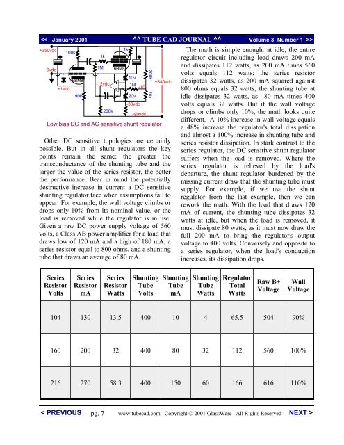
Low bias DC and AC sensitive shunt regulator<br />
Other DC sensitive topologies are certainly<br />
possible. But in all shunt regulators the key<br />
points remain the same: the greater the<br />
transconductance of the shunting tube and the<br />
larger the value of the series resistor, the better<br />
the performance. Bear in mind the potentially<br />
destructive increase in current a DC sensitive<br />
shunting regulator face when assumptions fail to<br />
appear. For example, the wall voltage climbs or<br />
drops only 10% from its nominal value, or the<br />
load is removed while the regulator is in use.<br />
Given a raw DC power supply voltage of 560<br />
volts, a Class AB power amplifier for a load that<br />
draws low of 120 mA and a high of 180 mA, a<br />
series resistor equal to 800 ohms, and a shunting<br />
tube that draws an average of 80 mA.<br />
Series<br />
Resistor<br />
Volts<br />
100k<br />
6BM8<br />
90k<br />
< PREVIOUS<br />
Series<br />
Resistor<br />
mA<br />
1k<br />
1M<br />
-12vdc<br />
Series<br />
Resistor<br />
Watts<br />
<strong>Shunt</strong>ing<br />
<strong>Tube</strong><br />
Volts<br />
<strong>Shunt</strong>ing<br />
<strong>Tube</strong><br />
mA<br />
The math is simple enough: at idle, the entire<br />
regulator circuit including load draws 200 mA<br />
and dissipates 112 watts, as 200 mA times 560<br />
volts equals 112 watts; the series resistor<br />
dissipates 32 watts, as 200 mA squared against<br />
800 ohms equals 32 watts; the shunting tube at<br />
idle dissipates 32 watts, as 80 mA times 400<br />
volts equals 32 watts. But if the wall voltage<br />
drops or climbs only 10%, the math looks quite<br />
different. A 10% increase in wall voltage equals<br />
a 48% increase the regulator's total dissipation<br />
and almost a 100% increase in shunting tube and<br />
series resistor dissipation. In stark contrast to the<br />
series regulator, the DC sensitive shunt regulator<br />
suffers when the load is removed. Where the<br />
series regulator is relieved by the load's<br />
departure, the shunt regulator burdened by the<br />
missing current draw that the shunting tube must<br />
supply. For example, if we use the shunt<br />
regulator from the last example, then we can<br />
rework the math. With the load that draws 120<br />
mA of current, the shunting tube dissipates 32<br />
watts at idle, but when the load is removed, it<br />
must dissipate 80 watts, as it must now draw the<br />
full 200 mA to bring the regulator's output<br />
voltage to 400 volts. Conversely and opposite to<br />
a series regulator, when the load's conduction<br />
increases, its dissipation drops.<br />
<strong>Shunt</strong>ing<br />
<strong>Tube</strong><br />
Watts<br />
<strong>Regulator</strong><br />
Total<br />
Watts<br />
Raw B+<br />
Voltage<br />
Wall<br />
Voltage<br />
104 130 13.5 400 10 4 65.5 504 90%<br />
160 200 32 400 80 32 112 560 100%<br />
216 270 58.3 400 150 60 166 616 110%<br />
pg. 7<br />
200k<br />
6BM8<br />
1k<br />
10v<br />
1M<br />
20v<br />
-30vdc<br />
-10<br />
-90vdc<br />
260k<br />
20k<br />
+340vdc<br />
www.tubecad.com Copyright © 2001 GlassWare All Rights Reserved NEXT >


