tender document index - Hindustan Petroleum Corporation Limited
tender document index - Hindustan Petroleum Corporation Limited
tender document index - Hindustan Petroleum Corporation Limited

Create successful ePaper yourself
Turn your PDF publications into a flip-book with our unique Google optimized e-Paper software.
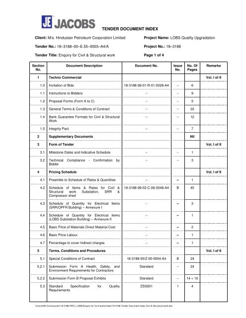
TENDER DOCUMENT INDEX<br />
Client: M/s. <strong>Hindustan</strong> <strong>Petroleum</strong> <strong>Corporation</strong> <strong>Limited</strong> Project Name: LOBS Quality Upgradation<br />
Tender No.: 18–3188–00–E.55–0003–A4/A Project No.: 18–3188<br />
Tender Title: Enquiry for Civil & Structural work Page 1 of 4<br />
Section<br />
No.<br />
Document Description Document No. Issue<br />
No.<br />
\\nmumfil01\Construction\18 3188 HPCL LOBS\Enquiry for Civil works\Index\18 3188 Tender Document Index Civil & Structural work.doc<br />
No. Of<br />
Pages<br />
Remarks<br />
1 Techno Commercial Vol. I of II<br />
1.0 Invitation of Bids 18-3188-99-01-R-01-0028-A4 -- 6<br />
1.1 Instructions to Bidders -- -- 9<br />
1.2 Proposal Forms (Form A to C) -- -- 5<br />
1.3 General Terms & Conditions of Contract -- -- 33<br />
1.4 Bank Guarantee Formats for Civil & Structural<br />
Work<br />
-- -- 12<br />
1.5 Integrity Pact -- -- 7<br />
2 Supplementary Documents Nil<br />
3 Form of Tender Vol. I of II<br />
3.1 Milestone Dates and Indicative Schedule -- -- 1<br />
3.2 Technical Compliance - Confirmation by<br />
Bidder<br />
-- -- 3<br />
4 Pricing Schedule Vol. I of II<br />
4.1 Preamble to Schedule of Rates & Quantities -- -- 1<br />
4.2 Schedule of Items & Rates for Civil &<br />
Structural work Substation, SRR &<br />
Compressor shed<br />
4.3 Schedule of Quantity for Electrical Items<br />
(SRR/OPFR Building) – Annexure I<br />
4.4 Schedule of Quantity for Electrical Items<br />
(LOBS Substation Building) – Annexure II<br />
18-3188-99-02-C-06-0048-A4 B 45<br />
-- -- 3<br />
-- -- 1<br />
4.5 Basic Price of Materials Direct Material Cost -- -- 2<br />
4.6 Basic Price Labour -- -- 1<br />
4.7 Percentage to cover Indirect charges -- -- 1<br />
5 Terms, Conditions and Procedures Vol. I of II<br />
5.1 Special Conditions of Contract 18-3188-00/Z-00-0004-A4 B 24<br />
5.2.1 Submission Form A Health, Safety, and<br />
Environment Requirements for Contractors<br />
Standard -- 24<br />
5.2.2 Submission Form B Proposal Exhibits Standard -- 14 + 10<br />
5.3 Standard Specification for Quality<br />
Requirements<br />
ZSS001 1 4
TENDER DOCUMENT INDEX<br />
Client: M/s. <strong>Hindustan</strong> <strong>Petroleum</strong> <strong>Corporation</strong> <strong>Limited</strong> Project Name: LOBS Quality Upgradation<br />
Tender No.: 18–3188–00–E.55–0003–A4/A Project No.: 18–3188<br />
Tender Title: Enquiry for Civil & Structural work Page 2 of 4<br />
Section<br />
No.<br />
Document Description Document No. Issue<br />
No.<br />
5.4 Standard Specification for using QC Check<br />
sheets<br />
\\nmumfil01\Construction\18 3188 HPCL LOBS\Enquiry for Civil works\Index\18 3188 Tender Document Index Civil & Structural work.doc<br />
No. Of<br />
Pages<br />
ZSS002 1 5<br />
5.5 Applicable QC Check sheets Standard -- 2 + 45<br />
5.6 Specification for Field HSE Activities 18-3188-99-00-HSC-02-0007 B 58<br />
Remarks<br />
6 Technical Documentation -- -- -- Vol. I of II<br />
6.1 Specification for earth work 18-3188-99-00-C-02-0013 0 7<br />
6.2 Specification for plain and reinforcement<br />
concrete<br />
18-3188-99-00-S-02-0014<br />
1 18<br />
6.3 Specification for ready mix concrete 18-3188-99-00-S-02-0015 0 7<br />
6.4 Specification for masonry and plastering 18-3188-99-00-A-02-0017 0 9<br />
6.5 Specification for construction of drainage and<br />
sewers<br />
18-3188-99-00-C-02-0018<br />
0 8<br />
6.6 Specification for Anti-Termite Treatment 18-3188-99-00-A-02-0019 0 4<br />
6.7 Specification for water proofing 18-3188-99-00-A-02-0020 0 3<br />
6.8 Specification for site grading 18-3188-99-00-C-02-0021 0 4<br />
6.9 Standard Specification for miscellaneous<br />
fabrication work<br />
6.10 Specification for doors, windows and<br />
ventilators<br />
18-3188-99-00-S-02-0022<br />
18-3188-99-00-A-02-0023<br />
0 5<br />
0 9<br />
6.11 Specification for concrete paving 18-3188-99-00-C-02-0025 0 7<br />
6.12 Specification for metal sheet roofing and<br />
cladding<br />
18-3188-99-00-S-02-0026<br />
0 6<br />
6.13 Specification for Chain link fencing 18-3188-99-02-C-01-0028 0 5<br />
6.14 Specification for floor finishes and wall tiling 18-3188-99-00-A-02-0030 0 9<br />
6.15 Specification for Structural steel work 18-3188-99-00-S-02-0032 0 17<br />
6.16 Specification for Painting 18-3188-99-00-V-02-0005 0 15<br />
6.17 Specifications for False Ceiling 18-3188-99-02-A-02-0049 0 7<br />
6.18 Specifications for False Flooring 18-3188-99-02-A-02-0050 0 5<br />
6.19 Specifications for Plumbing, Sanitary Works<br />
and Drainage<br />
18-3188-99-02-C-02-0051 0 10<br />
6.17 Job Specification Electrical 18-3188-99-00-E-02-0103-A4 1 10<br />
6.18 Standard specification for Electrical<br />
Installation.<br />
3188-E SS-26 0 33
TENDER DOCUMENT INDEX<br />
Client: M/s. <strong>Hindustan</strong> <strong>Petroleum</strong> <strong>Corporation</strong> <strong>Limited</strong> Project Name: LOBS Quality Upgradation<br />
Tender No.: 18–3188–00–E.55–0003–A4/A Project No.: 18–3188<br />
Tender Title: Enquiry for Civil & Structural work Page 3 of 4<br />
Section<br />
No.<br />
Document Description Document No. Issue<br />
No.<br />
\\nmumfil01\Construction\18 3188 HPCL LOBS\Enquiry for Civil works\Index\18 3188 Tender Document Index Civil & Structural work.doc<br />
No. Of<br />
Pages<br />
Remarks<br />
7 Drawing Vol. II of II<br />
7.1 Civil Drawings<br />
7.1.1 SRR Sub Building Architecture Ground Floor<br />
Plan<br />
7.1.2 SRR Building Roof plan Section and<br />
Elevations<br />
7.1.3 Substation Building Architecture Plan &<br />
Section<br />
7.1.4 Finished Schedule – SRR and Sub station<br />
building<br />
7.1.5 Foundation layout and details of columns for<br />
Sub station<br />
18-3188-99-02-A-01-1005-A1<br />
18-3188-99-02-A-01-1006-A1<br />
18-3188-99-02-A-01-1009-A1<br />
18-3188-99-02-A-01-1015-A3<br />
18-3188-99-02-C-01-0185-A0<br />
E 1<br />
B 1<br />
B 1<br />
B 1<br />
B 1<br />
7.1.6 Sub Station Building Details of beam and slab 18-3188-99-02-C-01-0186-A0 B 1<br />
7.1.7 Sub Station Building Details of beam and slab 18-3188-99-02-C-01-0187-A0 B 1<br />
7.1.8 SRR and Operator Building Foundation layout 18-3188-99-02-C-01-0191-A0 B 1<br />
7.1.9 SRR and Operator Building Plinth Beam<br />
Layout<br />
18-3188-99-02-C-01-0192-A0<br />
B 1<br />
7.1.10 SRR and Operator Building Roof Beam Layout 18-3188-99-02-C-01-0193-A0 B 1<br />
7.1.11 Layout, Elevation and Sectional details for Air<br />
Compressor, Air Receiver and Air Dryer Unit<br />
Shed.<br />
7.2 Electrical Drawings<br />
18-3188-99-02-C-01-0156-A0<br />
A 1<br />
7.2.1 Miscellaneous Details Power 18-3188-99-00-E-01-0052-A3 0 60<br />
7.2.2 Miscellaneous Details Earthing 18-3188-99-00-E-01-0053-A3 0 40<br />
7.2.3 Miscellaneous Details Lighting. 18-3188-99-00-E-01-0054-A3 0 50<br />
7.2.4 Typical Single Line Diagrams – Lighting<br />
Distribution Board and Power Distribution<br />
Board – Index<br />
7.2.5 Single Line Diagram – Lighting Distribution<br />
Board Incomer Feeder<br />
7.2.6 Single Line Diagram – Lighting Distribution<br />
Board Outgoing Feeder<br />
7.2.7 Single Line Diagram – Lighting Distribution<br />
Board Lighting & Power Panel<br />
7.2.8 Single Line Diagram – Lighting Distribution<br />
Board Power Distribution Board<br />
18-3188-99-00-E-01-0113-A4 A 1<br />
18-3188-99-00-E-01-0113-A3<br />
18-3188-99-00-E-01-0113-A4<br />
18-3188-99-00-E-01-0113-A4<br />
18-3188-99-00-E-01-0113-A4<br />
A<br />
A<br />
A<br />
A<br />
1 Sheet 2 of 7<br />
1 Sheet 3 of 7<br />
1 Sheet 4 of 7<br />
1 Sheet 5 of 7
TENDER DOCUMENT INDEX<br />
Client: M/s. <strong>Hindustan</strong> <strong>Petroleum</strong> <strong>Corporation</strong> <strong>Limited</strong> Project Name: LOBS Quality Upgradation<br />
Tender No.: 18–3188–00–E.55–0003–A4/A Project No.: 18–3188<br />
Tender Title: Enquiry for Civil & Structural work Page 4 of 4<br />
Section<br />
No.<br />
Document Description Document No. Issue<br />
No.<br />
7.2.9 Single Line Diagram – Lighting Distribution<br />
Board Critical Lighting Panel<br />
18-3188-99-00-E-01-0113-A4<br />
\\nmumfil01\Construction\18 3188 HPCL LOBS\Enquiry for Civil works\Index\18 3188 Tender Document Index Civil & Structural work.doc<br />
A<br />
No. Of<br />
Pages<br />
Remarks<br />
1 Sheet 6 of 7
INVITATION OF BIDS<br />
FOR<br />
CIVIL & STRUCTURAL WORKS OF SATELLITE RACK ROOM,<br />
SUBSTATION & COMPRESSOR SHEDS<br />
AT<br />
HINDUSTAN PETROLEUM CORPORATION LTD<br />
MUMBAI REFINERY<br />
LOBS QUALITY UPGRADATION PROJECT<br />
National bidding<br />
DOCUMENT NO : 18-3188-99-01-R-01-0028-A4<br />
H:\commercial_<strong>tender</strong>\Civil Structural Work\final\Invitation of Bids_Civil Structural Works_1.doc
HINDUSTAN PETROLEUM CORPN LTD.<br />
(A Government of India Undertaking)<br />
(Refineries Division)<br />
JACOBS ENGINEERING INDIA PVT. LTD.,<br />
MUMBAI<br />
INVITATION FOR CIVIL & STRUCTURAL WORK OF SATELLITE RACK ROOM, SUBSTATION<br />
& COMPRESSOR SHED FOR LUBE OIL BASE STOCK (LOBS) QUALITY UPGRADATION<br />
PROJECT AT MUMBAI REFINERY, MAHARASHTRA (INDIA)<br />
(National Competitive bidding)<br />
1. M/s. <strong>Hindustan</strong> <strong>Petroleum</strong> <strong>Corporation</strong> <strong>Limited</strong> (HPCL) are implementing Lube Oil Base<br />
Stock (LOBS) Quality Upgradation Facilities consisting of Process Units, Offsites, and<br />
Utilities at their existing Refinery at Mumbai, in the State of Maharashtra (India) located<br />
within the City of Mumbai.<br />
2. For execution of this project M/s.Jacobs Engineering India Private <strong>Limited</strong> (JACOBS),<br />
Mumbai, have been retained as the Project Management Consultant (PMC). JACOBS, on<br />
behalf of HPCL, hereby invite bids for Civil & Structural Work for Satellite Rack Room,<br />
Substation & Compressor Sheds, including Electrical Lighting works for Satellite Rack<br />
Room and Lighting Protection of Substation, meeting qualification criteria of bidders as<br />
specified in clause 3.0.<br />
3. Brief scope of work<br />
It is proposed to construct the following buildings/structures:<br />
Sl. no. Description<br />
1 Satellite Rack Room (SRR) and Operator Building<br />
2 Electrical Substation<br />
3 Air Compressor Sheds<br />
The brief scope of work of the contractor covers supply of all tools, tackles, manpower,<br />
supervision, materials (consumable/non-consumable), transportation, loading/unloading,<br />
to execute the job including earthworks in excavation and backfilling in all types of soil &<br />
rocks, filling, disposal of surplus earth/debris to out of refinery premises, PCC/RCC in all<br />
types of foundations & super structure, blast proofing RCC walls, Brick masonry in<br />
foundations & superstructures, flooring, waterproofing, painting, plumbing, drainage works<br />
etc. including supply, fabrication and erection of structural steel works and Electrical works<br />
in SRR building, and all other jobs, complete as per the <strong>tender</strong> <strong>document</strong> for all the above<br />
mentioned buildings/ structures. Detailed scope of work is elaborated in <strong>tender</strong> <strong>document</strong>.<br />
The scaffolding and shuttering works shall be done using metallic scaffolding and metallic<br />
shuttering plates only during the execution of entire job.<br />
H:\commercial_<strong>tender</strong>\Civil Structural Work\final\Invitation of Bids_Civil Structural Works_1.doc Page 2 of 6
HINDUSTAN PETROLEUM CORPN LTD.<br />
(A Government of India Undertaking)<br />
(Refineries Division)<br />
JACOBS ENGINEERING INDIA PVT. LTD.,<br />
MUMBAI<br />
INVITATION FOR CIVIL & STRUCTURAL WORK OF SATELLITE RACK ROOM, SUBSTATION<br />
& COMPRESSOR SHED FOR LUBE OIL BASE STOCK (LOBS) QUALITY UPGRADATION<br />
PROJECT AT MUMBAI REFINERY, MAHARASHTRA (INDIA)<br />
(National Competitive bidding)<br />
All RCC works shall be done using approved mix of Ready Mix Concrete (RMC) brought<br />
from out of refinery premises from approved vendors.<br />
Contractor to start the work at all the fronts simultaneously, as the completion period for<br />
each building/structure is from the date of LOI/PO or handing over of site to contractor,<br />
which ever is later.<br />
Contractor shall make his own arrangement for construction power, transportation of all<br />
required material from his stores, fabrication shop out side the Refinery to construction<br />
site.<br />
Contractor shall not be provided with any space for his storage/ ware house and<br />
fabrication inside HPCL area. He shall carry out prefabrication of all the parts outside<br />
HPCL. Concrete mixing shall not be allowed in side the refinery premise.<br />
HSE Requirement<br />
Contractor to strictly comply with all the prevailing safety and security rules of refinery<br />
during the execution of job and be fully aware of the safety requirement, compliances as<br />
indicated in the <strong>tender</strong>. Contractor shall have exclusive set up for HSE.<br />
4. QUALIFICATION CRITERIA<br />
Technical Qualification Criteria/ Experience:<br />
• The bidders shall have experience of having successfully completed similar<br />
building/shed work(s) during last seven years, ending last day of month previous to the<br />
one in which bids are invited, should be either of the following :<br />
a. Three similar works costing not less than Rs. 2.60 Crores each. (Rupees Two<br />
Crores Sixty Lakhs)<br />
b. Two similar works costing not less than Rs. 3.25 Crores each. (Rupees Three<br />
Crores Twenty Five Lakhs)<br />
c. One similar work costing not less than Rs. 5.20 Crores. (Rupees Five Crores<br />
Twenty Lakhs)<br />
H:\commercial_<strong>tender</strong>\Civil Structural Work\final\Invitation of Bids_Civil Structural Works_1.doc Page 3 of 6
HINDUSTAN PETROLEUM CORPN LTD.<br />
(A Government of India Undertaking)<br />
(Refineries Division)<br />
JACOBS ENGINEERING INDIA PVT. LTD.,<br />
MUMBAI<br />
INVITATION FOR CIVIL & STRUCTURAL WORK OF SATELLITE RACK ROOM, SUBSTATION<br />
& COMPRESSOR SHED FOR LUBE OIL BASE STOCK (LOBS) QUALITY UPGRADATION<br />
PROJECT AT MUMBAI REFINERY, MAHARASHTRA (INDIA)<br />
(National Competitive bidding)<br />
• The bidder also must have done minimum 1000 m 3 of concrete work in any of the<br />
building/shed similar works during last 7 years.<br />
Financial Criteria :<br />
• Annual Turnover: Annual turnover of the bidder shall not be less than Rs. 7 Crores,<br />
as per the audited annual financial results in any one of the last three preceding<br />
audited financial years.<br />
• Net Worth: Net worth of the bidder as per the latest audited annual financial results<br />
shall be positive. However, Central Public Sector Enterprises are exempted from this<br />
requirement.<br />
Note : Both the above criteria (Technical & Financial) to be met for qualifications of bidders.<br />
5. Earnest Money Deposit (EMD)/ Bid Security:<br />
Bids must be accompanied with Earnest Money Deposit/Bid security of Rs. 12 Lakhs. Bids<br />
not accompanied with requisite EMD shall be rejected. EMD shall be in favour of<br />
<strong>Hindustan</strong> <strong>Petroleum</strong> <strong>Corporation</strong> <strong>Limited</strong>, payable at Mumbai in form of crossed demand<br />
draft or Bank Guarantee on non-judicial stamp paper of value not less than Rs. 100 from<br />
nationalized Indian bank ( not cooperative bank) , in prescribed Performa, valid for four<br />
months plus two months claim period from due date of submission.<br />
Central Public Sector Enterprises are exempted from furnishing EMD, subject to<br />
declaration to that effect.<br />
6. Time for Completion:<br />
Time schedule for the contract shall be 11 months from date of Letter of Intent. The<br />
liquidated damages shall be applicable after 11 months, for reasons attributable to<br />
contractor. However, the successful bidder shall confirm to deploy adequate resources<br />
and plan to complete the Substation building in 10 months and compressor sheds in 6<br />
months.<br />
H:\commercial_<strong>tender</strong>\Civil Structural Work\final\Invitation of Bids_Civil Structural Works_1.doc Page 4 of 6
HINDUSTAN PETROLEUM CORPN LTD.<br />
(A Government of India Undertaking)<br />
(Refineries Division)<br />
JACOBS ENGINEERING INDIA PVT. LTD.,<br />
MUMBAI<br />
INVITATION FOR CIVIL & STRUCTURAL WORK OF SATELLITE RACK ROOM, SUBSTATION<br />
& COMPRESSOR SHED FOR LUBE OIL BASE STOCK (LOBS) QUALITY UPGRADATION<br />
PROJECT AT MUMBAI REFINERY, MAHARASHTRA (INDIA)<br />
(National Competitive bidding)<br />
7. Salient features of bidding <strong>document</strong> are as follows:<br />
Tender No<br />
:<br />
18-3188-00-E550003-A<br />
Name of Work : Civil & Structural Work for SRR, Substation & Compressor<br />
Shed for LOBS Quality Upgradation project at HPCL Mumbai<br />
Refinery<br />
Cost of Tender<br />
Document<br />
:<br />
Rs. 5,000 (by way of Demand draft in favour of “<strong>Hindustan</strong><br />
<strong>Petroleum</strong> <strong>Corporation</strong> Ltd.” Payable at Mumbai on<br />
Nationalized Bank only and not cooperative bank.)<br />
Sale Period : Starting from 11.10.2007 to 20.11.2007<br />
Contact Person : Mr. S. B. Nayan, E.D.-Procurement; Jacobs,<br />
Tel No. : 91.22.67562000,<br />
Fax No.: 91.22.27573049<br />
Date of Submission of<br />
Tender Document<br />
: 21.11.2007 (upto 14.00 hours)<br />
8. Complete set of bidding <strong>document</strong> (non-transferable) can be purchased on any working<br />
day (Monday to Friday) from Jacobs Engineering India Private <strong>Limited</strong>, H&G House,<br />
Sector 11, Plot No. 12, CBD Belapur, Navi Mumbai – 400 614 (India), upon payment of<br />
cost of bidding <strong>document</strong> in form of crossed demand draft from any Indian nationalized<br />
bank, in favour of <strong>Hindustan</strong> <strong>Petroleum</strong> <strong>Corporation</strong> <strong>Limited</strong>, payable at Mumbai.<br />
9. Consortium / Joint venture bids are not acceptable.<br />
10. Bidder should not be under liquidation, court receivership or similar proceedings<br />
H:\commercial_<strong>tender</strong>\Civil Structural Work\final\Invitation of Bids_Civil Structural Works_1.doc Page 5 of 6
HINDUSTAN PETROLEUM CORPN LTD.<br />
(A Government of India Undertaking)<br />
(Refineries Division)<br />
JACOBS ENGINEERING INDIA PVT. LTD.,<br />
MUMBAI<br />
INVITATION FOR CIVIL & STRUCTURAL WORK OF SATELLITE RACK ROOM, SUBSTATION<br />
& COMPRESSOR SHED FOR LUBE OIL BASE STOCK (LOBS) QUALITY UPGRADATION<br />
PROJECT AT MUMBAI REFINERY, MAHARASHTRA (INDIA)<br />
(National Competitive bidding)<br />
11. HPCL/Jacobs shall not be responsible for any expenses incurred by bidders in connection<br />
with the preparation & delivery of their bids, site visits and other expense incurred during<br />
bidding process.<br />
12. HPCL/Jacobs shall allow purchase preference to Indian Central Govt. Public Sector<br />
undertaking/Enterprises under existing policies of Govt. of India.<br />
13. Fax/Email bids shall not be accepted.<br />
14. Bidders shall have to submit a duly signed and stamped copy of “Integrity pact” on plain<br />
paper along with their bid on the format enclosed with bidding <strong>document</strong>. Bids submitted<br />
by bidders without a signed & stamped Integrity pact will be rejected.<br />
15. SITE VISIT<br />
Contractors intending to visit site may please intimate the names of the persons<br />
(maximum 2) to Jacobs (PMC) on or before 22.10.2007, so that visit can be arranged on a<br />
suitable date.<br />
16. Prospective bidder shall submit their sealed bids to the Executive Director -<br />
Procurement, Jacobs Engineering India Private <strong>Limited</strong>, H&G House, Sector 11, Plot<br />
No. 12, CBD Belapur, Navi Mumbai – 400 614 (India) latest by 1400 hours (IST) on<br />
21.11.2007.<br />
17. Bids received after due date and time shall be rejected and representative of such bidders<br />
shall not be allowed to attend the bid opening.<br />
18. HPCL / JACOBS reserve the right to reject any or all bids at their sole discretion without<br />
assigning any reason whatsoever.<br />
S.B. NAYAN<br />
Executive Director – Procurement<br />
Jacobs Engineering India Private <strong>Limited</strong><br />
NAVI MUMBAI.<br />
H:\commercial_<strong>tender</strong>\Civil Structural Work\final\Invitation of Bids_Civil Structural Works_1.doc Page 6 of 6
HPCL – Mumbai Refinery INSTRUCTION TO BIDDERS CIVIL & STRUCTURAL<br />
WORK<br />
18-3188 Page 2 of 9<br />
H:\commercial_<strong>tender</strong>\Civil Structural Work\final\01_1_itb_Civil Structural Work.doc<br />
INDEX<br />
1. INTRODUCTION<br />
2. OWNER’S CONSULTANT<br />
3. COST OF BIDDING<br />
4. SITE LOCATION<br />
5. TENDER DOCUMENTS<br />
6. CLARIFICATION OF TENDER DOCUMENT<br />
7. AMENDMENT OF TENDER DOCUMENTS<br />
8. PREPARATION/ SUBMISSION OF THE TENDER<br />
9. SCHEDULE OF ITEMS & RATES<br />
10. PERIOD OF VALIDITY OF BIDS<br />
11. FORMAT AND SIGNING OF BID<br />
12. SEALING AND MARKING OF BIDS<br />
13. DATE FOR SUBMISSION OF BIDS<br />
14. ALL PAGES TO BE INITIALLED<br />
15. PRICES TO BE IN FIGURES AND WORDS<br />
16. CORRECTIONS AND ERASURES<br />
17. LATE BIDS<br />
18. OPENING OF BIDS BY OWNER/CONSULTANT<br />
19. CLARIFICATION OF BIDS<br />
20. TECHNO-COMMERCIAL EXAMINATION OF BIDS<br />
21. WAIVER OF DEVIATION AND CONDITIONS<br />
22. COMPLETE SCOPE OF SUPPLIES / WORK<br />
23. OPENING OF PRICE BIDS<br />
24. EVALUATION AND COMPARISON OF BIDS<br />
25. CONTACTING OWNER / CONSULTANT<br />
26. OWNER’S RIGHT TO ACCEPT/REJECT BIDS<br />
27. NOTIFICATION OF AWARD<br />
28. PURCHASE ORDER
CIVIL & STRUCTURAL<br />
WORK<br />
INSTRUCTIONS TO BIDDERS HPCL – Mumbai Refinery<br />
Page 3 of 9 18 - 3188<br />
1.0 INTRODUCTION<br />
1.1 <strong>Hindustan</strong> <strong>Petroleum</strong> <strong>Corporation</strong> <strong>Limited</strong> (HPCL) (hereafter referred as (‘OWNER’) intends to<br />
set up a Lube Oil Base Stock (LOBS) Quality Upgradation Project of 200,000 MTPA consisting<br />
of process units, offsites and utilities at the Mumbai Refinery.<br />
1.2<br />
For implementation of the above project, the Owner is inviting sealed Bids, under single stage<br />
two Bid System, for the entire supplies and work covered under the Tender Documents<br />
(hereinafter for the purpose of these instructions collectively referred to as the ‘SUPPLY) from<br />
Bidders.<br />
1.3 The Completion schedule shall be strictly as per section titled “Time for Completion” as per<br />
clause No. 6.0 of Invitation of Bids. All Bids shall be completed and returned in accordance with<br />
and within the time provided in these Instructions to Bidders.<br />
2.0 OWNER’S CONSULTANT<br />
2.1<br />
For this Project, the Owner has appointed M/s. Jacobs Engineering India Private <strong>Limited</strong><br />
(JACOBS) as the Engineering, Procurement and Construction Management (EPCM)<br />
(hereinafter referred to as the ‘Consultant’ of the Owner) involved in the Bidding process and<br />
they will be performing various actions in relation to the Bidding process and in the evaluation of<br />
Bids for and on behalf of the Owner. “Consultant” as referred to in these Instructions to Bidders<br />
or other parts of Tender Document is only intended to clarify to the Bidder the Owner’s intention<br />
that operations involved in the bidding process, including the evaluation of Bids, shall be<br />
conducted by the Owner through Consultant.<br />
3.0 COST OF BIDDING<br />
3.1<br />
The Bidder shall bear all costs associated with preparation and delivery of its Bids including<br />
costs and expenses related to visit to site(s), and the OWNER / CONSULTANT shall in no case<br />
be responsible or liable for those costs regardless of the outcome of the Bidding process.<br />
4.0 SITE LOCATION<br />
4.1 Site Location<br />
The site is located within Mumbai Refinery, which is situated within the City of Mumbai in<br />
Maharashtra State, India.<br />
5.0 TENDER DOCUMENTS<br />
5.1<br />
The Bidder is expected to examine the Tender Documents, including all instructions, forms,<br />
terms, specifications, drawings and other <strong>document</strong>s and requirements of the Tender<br />
Document. Failure to furnish all information required by the Tender Document or submission of<br />
a Bid not substantially responsive to the Tender Document in every respect shall result in the<br />
rejection of the Bid.<br />
5.2 Any amendment issued in accordance with clause 7.0 below shall also form part of the Bid<br />
Document.<br />
H:\commercial_<strong>tender</strong>\Civil Structural Work\final\01_1_itb_Civil Structural Work.doc
HPCL – Mumbai Refinery INSTRUCTION TO BIDDERS CIVIL & STRUCTURAL<br />
WORK<br />
18-3188 Page 4 of 9<br />
6.0 CLARIFICATION OF TENDER DOCUMENT<br />
6.1 Bidder shall examine the Tender Documents thoroughly. Bidder requiring any clarifications on<br />
the Tender Document may notify the Owner and Consultant in writing not later than 7 working<br />
days before due date (not on Saturday/ Sunday) as per proposal form, FORM-C enclosed in the<br />
Tender Documents along with the Tender. Consultant shall issue appropriate clarification or<br />
amendment, if required. Failure of Bidder to comply with the aforesaid shall not excuse the<br />
Bidders from performing the services in accordance with the Agreement and, if subsequently<br />
awarded, the Purchase Order.<br />
7.0 AMENDMENT OF TENDER DOCUMENTS<br />
7.1<br />
At any time prior to the date for submission of Bids as well as upto priced Bid opening, the<br />
OWNER/CONSULTANT may, for any reason whether at its own initiative or in response to a<br />
clarification requested by prospective Bidders, modify the Tender Document by amendment.<br />
7.2 In order to provide time to prospective Bidders to take into account such amendment in<br />
preparing their Bids, OWNER/CONSULTANT may, at its discretion, extend the date for the<br />
submission of Bids.<br />
8.0 PREPARATION / SUBMISSION OF TENDER<br />
8.1 Bidder is required to make a proposal in a format as outlined below in order to achieve the<br />
objective of maintaining uniform proposal structure from all the Bidders.<br />
8.2 The Bid shall be submitted in Two parts viz. PART-A & PART-B in two separate sealed<br />
envelopes with due marking on the envelopes. The sealed envelopes of un-priced and<br />
priced part shall be put in another envelope and sealed before submission<br />
8.2.1 Priced and unpriced forms should be identical in all respects except that the price columns<br />
shall be kept blank in the unpriced Bids.<br />
8.2.2 All the envelopes shall be superscribed as follows:<br />
PART – A Techno-commercial / Unpriced Bid<br />
PART – B Priced Bid<br />
8.2.3 Techno-commercial / Unpirced Bid (PART-A) shall be submitted in 1 original and 4 copies (5<br />
sets in all) and shall contain the following <strong>document</strong>s :<br />
i. Letter of submission.<br />
ii Declaration as per proposal FORM-A duly signed & stamped by the Bidder in token of<br />
having received and read all volumes of the technical <strong>document</strong>s and having accepted<br />
and considered the same in preparing and submitting the Bid.<br />
iii List of Deviations (if any) to the commercial and technical Bid <strong>document</strong>s as per<br />
proposal FORM –B, technical deviations must be given separately for each discipline.<br />
iv Literature / Pamphlets (if applicable).<br />
H:\commercial_<strong>tender</strong>\Civil Structural Work\final\01_1_itb_Civil Structural Work.doc
CIVIL & STRUCTURAL<br />
WORK<br />
INSTRUCTIONS TO BIDDERS HPCL – Mumbai Refinery<br />
Page 5 of 9 18 - 3188<br />
v Section 3.1 – Time Schedule<br />
Section 3.2 – Technical Confirmation Requirements<br />
(As per Tender/ Contract Document Index)<br />
vi Section 5.2.1 – Submission Form A Health Safety and Environment Requirements for<br />
Contractors (As per Tender/ Contract Document Index)<br />
Section 5.2.2 - Submission Form B Proposal Exhibits<br />
(As per Tender/ Contract Document Index)<br />
8.2.4 Part B (Priced Bid) shall be submitted in 1 original and 1 copy (2 sets in all) and shall consist<br />
of :<br />
a) Copy of cover letter<br />
b) Price schedule as per Forms given in the Bid <strong>document</strong>s duly completed in all respects.<br />
8.3 Waiver of deviations and conditions (if any) as per proposal FORM-C, to be submitted before the<br />
opening of the priced Bid.<br />
8.4 Part B shall be submitted in a separate sealed envelope duly signed and stamped on each page<br />
superscribing on the sealed envelope “Price- Do not Open”. This part shall not contain any condition<br />
whatsoever failing which the Bids shall be liable for rejection. In case of any correction, the Bidder<br />
shall put his signature and his stamp. Eraser fluid will not be allowed for making any correction.<br />
8.5 The Bid requirements are explicitly stated in the Tender Document. Bidder is required to study<br />
these requirements in detail and make a proposal in an outline as defined above completely<br />
meeting these requirements. The offer must be complete in all respects, leaving no scope for<br />
ambiguity. It is in the interest of Bidder to submit complete & comprehensive proposal leaving no<br />
scope for OWNER/CONSULTANT to raise or ask for any further questions or clarifications, with a<br />
view that the proposal may be evaluated only on the basis of what has been submitted by the<br />
Bidder in the first instance in order to adhere to a very strict project schedule.<br />
8.6 The Bids shall be compiled in the form of specific section-wise responses to each section of the<br />
Tender Document, in order to establish that the Bids are adequately responsive.<br />
8.7 For the purpose of these <strong>document</strong>s the terms “Bid” and “<strong>tender</strong>”, “Bidding” and “<strong>tender</strong>ing” and<br />
other similar expressions are synonymous.<br />
9.0 SCHEDULE OF ITEMS & RATES<br />
9.1 This is an item rate <strong>tender</strong> and quantities are tentative. Bidders to fill in ‘Schedule of Items &<br />
Rates’ given in the <strong>tender</strong>.<br />
10.0 PERIOD OF VALIDITY OF BIDS<br />
10.1 Bids shall remain valid for 120 (One Hundred Twenty) days after the deadline for Bid submission.<br />
A Bid valid for a shorter period may be rejected by the OWNER/ CONSULTANT as nonresponsive.<br />
10.2 Notwithstanding the above, the OWNER/ CONSULTANT may solicit the Bidder’s consent to an<br />
extension of the period of Bid validity. The request and the responses thereto shall be made in<br />
writing (by fax).<br />
H:\commercial_<strong>tender</strong>\Civil Structural Work\final\01_1_itb_Civil Structural Work.doc
HPCL – Mumbai Refinery INSTRUCTION TO BIDDERS CIVIL & STRUCTURAL<br />
WORK<br />
18-3188 Page 6 of 9<br />
10.3 A Bidder accepting the request for extension shall not be permitted to modify its Bid because of<br />
the extension, unless specifically invited to do so.<br />
11.0 FORMAT AND SIGNING OF BID<br />
11.1 The original Bid Form together with the Appendix and accompanying <strong>document</strong>s, clearly marked<br />
“Original”, plus 4 (Four) copies (5 copies in all), must be received by the Consultant by the date,<br />
time and place specified. In the event of any discrepancy between the original and the copies, the<br />
original shall govern.<br />
11.2 The original and all copies of the Bid shall be typed or written in indelible ink and shall be signed<br />
by the Bidder or a person or persons duly authorised to sign on behalf of the Bidder. Such<br />
authorization shall be indicated by written Power of Attorney accompanying the Bid. All pages of<br />
the Bid, except for unamended printed literature, shall be initialled by the person signing the Bid.<br />
The name and position held by each person signing must be typed or printed below the<br />
Signature.<br />
11.3 The Bid shall contain no interlineations, erasures or overwriting except as necessary to correct<br />
errors made by the Bidder, in which case such corrections shall be initialled by the person or<br />
persons signing the Bid<br />
12.0 SEALING AND MARKING OF BIDS<br />
12.1 The Bidder shall seal the original and copies of “PART-A - Techno-commercial Unpriced” &<br />
“PART-B – Priced” of the Bid in separate inner envelopes duly marking the envelopes ‘Original”<br />
or ‘Copy’, as applicable. The sealed envelopes of PART- A & PART- B’’ shall also be put in<br />
another envelope and sealed and marked to :<br />
The Executive Director - Procurement<br />
Jacobs Engineering India Private <strong>Limited</strong><br />
H&G House, Plot No. 12, Sector 11,<br />
CBD Belapur, Navi Mumbai – 400 614.<br />
INDIA.<br />
Telephone No. : 91.22.6756 2000<br />
Fax No. : 91.22.2757 3049<br />
12.2 All the two parts will bear the name of works ‘(the Project name)’, the Tender Document No.,<br />
Bidder’s name and address and the words ‘DO NOT OPEN BEFORE’ (date and time of opening<br />
of Bid as indicated in Invitation of Bids). The date and time of submission for all the two parts<br />
shall be same as mentioned in the Invitation of Bids.<br />
12.3 The outer envelope for all the two parts shall indicate the name and address of the Bidder to<br />
enable the Bid to be returned unopened in case it is declared to have been received ‘Late’.<br />
13.0 DATE FOR SUBMISSION OF BIDS<br />
13.1 The Original Bid, together with required copies must be received by the Consultant on or before<br />
the date, time and venue as specified in Invitation of Bids.<br />
H:\commercial_<strong>tender</strong>\Civil Structural Work\final\01_1_itb_Civil Structural Work.doc
CIVIL & STRUCTURAL<br />
WORK<br />
INSTRUCTIONS TO BIDDERS HPCL – Mumbai Refinery<br />
Page 7 of 9 18 - 3188<br />
13.2 The OWNER/ CONSULTANT may, at its discretion, extend the date for the submission of Bids by<br />
amending the Tender Documents, in which case all rights and obligations of the OWNER/<br />
CONSULTANT and Bidders previously subject to the date of submission of Bids, will thereafter be<br />
subject to the date, as extended.<br />
14.0 ALL PAGES TO BE INITIALLED<br />
14.1 All signatures in Bids shall be dated and shall bear a seal of the Bidders. In addition all pages of<br />
Bids shall be initialled at lower right hand corner by the Bidder or by a person holding power of<br />
attorney authorising him to sign on behalf of the Bidder before the submission of Bids.<br />
14.2 The Bidder shall sign and affix its seal on all pages of the priced Bid.<br />
15.0 PRICES TO BE IN FIGURES AND WORDS<br />
15.1 The Bidder shall fill the Schedule of Lumpsum Prices both in figures as well as in words in the<br />
Price Schedule forming part of the Tender Documents, in such a way that interpolation is not<br />
possible. The <strong>tender</strong>ed amount for the work shall be entered in the price schedule and duly<br />
signed by the Bidder.<br />
15.2 When there is a difference between the prices in figures and words, the amount which is lower of<br />
the two shall prevail.<br />
16.0 CORRECTIONS AND ERASURES<br />
16.1 All corrections and alterations in the Tender shall be signed in full by the Bidder with date. No<br />
erasures or overwriting and application of white fluid are permissible.<br />
17.0 LATE BIDS<br />
17.1 Any Tender received by CONSULTANT after the date and time for submission of Bids (including<br />
any extension(s) hereof) will be declared “Late” and rejected and returned unopened to the<br />
Bidder.<br />
18.0 OPENING OF BIDS BY OWNER/CONSULTANT<br />
18.1 Bids will be opened in the presence of the attending Bidders.<br />
18.2 The envelope containing Unpriced Technical Bid Part –A shall be opened in the presence of the<br />
Bidders on last day of submission of bids. Bidders may send their authorised person only to attend<br />
the Bid opening with an authority letter.<br />
19.0 CLARIFICATION OF BIDS<br />
19.1 To assist in the examination, evaluation and comparison of Bids, the OWNER/CONSULTANT may,<br />
at its discretion, ask the Bidder for a clarification of its Bid. All responses to request for clarification<br />
shall be in writing, and no change in the price or substance of the Bid shall be permitted unless<br />
specifically sought by Owner / Consultant.<br />
H:\commercial_<strong>tender</strong>\Civil Structural Work\final\01_1_itb_Civil Structural Work.doc
HPCL – Mumbai Refinery INSTRUCTION TO BIDDERS CIVIL & STRUCTURAL<br />
WORK<br />
18-3188 Page 8 of 9<br />
20.0 TECHNO-COMMERCIAL EXAMINATION OF BIDS<br />
20.1 The CONSULTANT will examine the Bids to determine whether they are complete, whether<br />
required securities have been furnished, whether the <strong>document</strong>s have been properly signed, and<br />
whether the Bids are generally in order.<br />
20.2 The Owner/Consultant shall determine to its satisfaction whether the Bidder has submitted<br />
responsive Bid and is qualified to perform satisfactorily the work and such determination shall not<br />
be open to question.<br />
20.3 The determination shall also take into account the Bidder’s financial and technical capabilities, as<br />
well as such other qualifications as the Owner/Consultant deem necessary and appropriate.<br />
21.0 WAIVER OF DEVIATIONS AND CONDITIONS<br />
21.1 Waiver of deviations and conditions (if any) as per Proposal FORM – C, should be submitted by<br />
the Bidders before the opening of the Priced Bid failing which the Priced Bid of concerned Bidder<br />
is liable for rejection.<br />
22.0 COMPLETE SCOPE OF SUPPLIES<br />
22.1 The complete scope of supplies / services has been defined in the Tender Document. Only<br />
those Bidders who take complete responsibility for the work and who quoted for the complete<br />
scope of supplies / services as contained in the Tender <strong>document</strong> shall be considered for further<br />
evaluation.<br />
23.0 OPENING OF PRICE BIDS<br />
23.1 Substantially responsive Bidders will be shortlisted by the OWNER/CONSULTANT for opening of<br />
price part of their Bid. Date, time and opening of their price Bid shall be informed to the shortlisted<br />
Bidders subsequently.<br />
23.2 The price Bids of the technically and commercially acceptable Bidders shall be opened in the<br />
presence of Bidder’s representative, who choose to attend, on the date and time to be intimated.<br />
The Bidder’s name, Bid price, discount if any, and such other details as the OWNER /<br />
CONSULTANT at its discretion may consider appropriate, shall be announced at the opening of<br />
price Bids.<br />
24.0 EVALUATION AND COMPARISON OF BIDS<br />
24.1 In evaluating the Tender, the OWNER / CONSULTANT will determine for each bid the evaluated<br />
price by adding the prices for following :<br />
a) Rates as quoted as per ‘Schedule of Rates & Quantities’’ and the required quantities<br />
24.2 Purchase Preference shall be applicable as per Government of India guidelines.<br />
24.3 Financial Loading, if any, shall be done considering rate of interest as 15% per annum.<br />
H:\commercial_<strong>tender</strong>\Civil Structural Work\final\01_1_itb_Civil Structural Work.doc
CIVIL & STRUCTURAL<br />
WORK<br />
INSTRUCTIONS TO BIDDERS HPCL – Mumbai Refinery<br />
Page 9 of 9 18 - 3188<br />
25.0 CONTACTING OWNER/CONSULTANT<br />
25.1 No Bidder shall contact the OWNER/CONSULTANT on any matter relating to its Bid from the<br />
time of Bid opening to the time, the Purchase Order is awarded, unless requested to in writing.<br />
Any effort by a Bidder to influence the OWNER/CONSULTANT in the Owner’s decisions in<br />
respect of Bid evaluation or Purchase Order award will result in the rejection of that Bidder’s bid.<br />
26.0 OWNER’S RIGHT TO ACCEPT/REJECT BIDS<br />
26.1 The OWNER reserves the right to accept or reject any Tender and to annul the Bidding process in<br />
toto and reject all Bids at any time prior to award of Contract without thereby incurring any liability to<br />
the affected Bidder(s) or any obligation to inform the affected Bidder(s) of the grounds of OWNER’S<br />
action.<br />
26.2 It is observed that many Bidders indulge in trading in contracts by entering into undisclosed backto-back<br />
arrangements for the whole or a substantial portion of a contractor’s obligations under<br />
the contract. Consequently, if a Bidder proposes to enter into any such arrangements upon a<br />
successful award of work or has in place any such arrangements which will become operative<br />
upon the award of work, the Bidder must make complete disclosure of such arrangement or<br />
proposed arrangement in its proposal, and all provisions applicable to sub-contractor (s) in terms<br />
of Tender Documents shall apply to such arrangements. Acceptance or otherwise of such<br />
arrangement will be under the discretion of the owner.<br />
26.3 If the existence of such an undisclosed arrangement is reasonably apprehended by the<br />
OWNER/CONSULTANT in the case of a Bidder, the OWNER may reject such Bidder’s bid as not<br />
responsive.<br />
26.4 If such an undisclosed arrangement is discovered after the award of work, such arrangement(s)<br />
shall be deemed to constitute an assignment of contract and a ground of termination pursuant to<br />
the provisions of termination under the General Purchase Conditions.<br />
27.0 NOTIFICATION OF AWARD<br />
27.1 The Owner will notify the successful Bidder in writing by letter and/or by fax of acceptance that their<br />
Bid has been accepted. The notification of award will constitute the formation of a Contract.<br />
28.0 PURCHASE ORDER<br />
28.1 Purchase Order shall be prepared after the notification of acceptance of Bid. The Tender<br />
Documents and addendum(s) and any modifications thereto and/or therefrom agreed by the<br />
OWNER shall be considered as order.<br />
28.2 A statement of agreed variations shall be prepared based on the finally agreed deviations if any, to<br />
the Tender Documents and all other correspondences forming part of the offer, prior to issue of<br />
notification of acceptance of Bid, shall be treated as null & void.<br />
H:\commercial_<strong>tender</strong>\Civil Structural Work\final\01_1_itb_Civil Structural Work.doc
01_2_proposal_form_Civil Stru work<br />
INDEX OF PROPOSAL FORMS<br />
S. NO. FORMAT NO. DESCRIPTION<br />
1. FORM A DECLARATION BY THE BIDDER<br />
2. FORM B EXCEPTIONS AND DEVIATIONS<br />
3. FORM C FORMAT OF LETTER OF WAIVER OF CONDITIONS / DEVIATIONS
BRIEF SCOPE OF WORK :<br />
TENDER NO :<br />
01_2_proposal_form_Civil Stru work<br />
DECLARATION BY THE BIDDER<br />
FORM – A<br />
We _______________________ (Name of the Bidder) hereby represent that we have gone through and<br />
understood the Tender Documents and our Bid has been prepared accordingly in compliance with the<br />
requirements stipulated in the said <strong>document</strong>s.<br />
We are submitting complete Tender Documents marked “Original” duly signed and stamped on each<br />
page in token of our acceptance as part of our Bid along with one copy of the CDs duly signed and the<br />
Master Index duly signed and stamped on each page. We undertake that said Tender <strong>document</strong>s shall<br />
be deemed to form part our Bid and in the event of award of work to us, all the parts shall be considered<br />
for constitution of Purchase Order.<br />
PLACE: ____________________<br />
DATE: ____________________<br />
SIGNED FOR AND ON BEHALF OF<br />
_______________________________<br />
(NAME OF BIDDER)<br />
NOTE: This declaration should be signed by the Bidder’s representative who is signing the Bid.
BRIEF SCOPE OF WORK :<br />
TENDER NO :<br />
S. TENDER DOCUMENT REFERENCE<br />
NO. PART NO. PAGE NO. CLAUSE<br />
NO.<br />
01_2_proposal_form_Civil Stru work<br />
EXCEPTIONS AND DEVIATIONS<br />
SUBJECT DEVIATION<br />
FORM – B<br />
NOTE: 1. If unavoidable, Bidder may stipulate deviations to the requirements of the Bid<br />
<strong>document</strong> only in this format<br />
2. Bidder shall furnish Technical and commercial deviations, if any, separately.<br />
3. Any deviations stated elsewhere in the bid shall not be taken into account and<br />
may render the bid non-responsive and liable to be rejected.<br />
STAMP & SIGNATURE OF BIDDER : ___________________________<br />
NAME OF BIDDER : ___________________________<br />
DATE :
FORMAT OF LETTER OF WAIVER OF CONDITIONS / DEVIATIONS<br />
ON COMPANY LETTER HEAD<br />
BRIEF SCOPE OF WORK :<br />
TENDER NO :<br />
01_2_proposal_form_Civil Stru work<br />
FORM – C<br />
We _________________(Name of the Bidder) hereby agree to fully comply with, abide and accept<br />
without variation, deviation or reservation all technical, commercial and other conditions whatsoever of<br />
the Bidding <strong>document</strong>s and all Addenda/ Corrigenda/ Amendments/ Clarifications issued by the<br />
<strong>Hindustan</strong> <strong>Petroleum</strong> <strong>Corporation</strong> <strong>Limited</strong>.<br />
We further hereby waive, withdraw and abandon any and all deviations, variations, objections or<br />
reservations whatsoever hereto set out, given or indicated in our offer, clarifications, correspondence,<br />
communications or otherwise with a view that the final price bid submitted may be treated to conform in<br />
all respects, with the terms and conditions of the said Tender <strong>document</strong>s including all Addenda/<br />
Corrigenda/ Amendments.<br />
We further hereby confirm that the currencies of price quoted in the price bid are as per the provisions<br />
of the Bidding <strong>document</strong>s and there is no deviation to the provisions in the final price bid.<br />
** The letter of Waiver must be signed by the person(s) authorized to sign.<br />
** For and on behalf of<br />
Authorised signatory
HPCL - Mumbai GENERAL TERMS AND CONDITIONS OF CONTRACT CIVIL &<br />
STRUCTURAL WORK<br />
18-3188 Page 2 of 33<br />
1 PRELIMINARY<br />
1.1 This is a Contract for execution of ___________________________________ work at<br />
______________________. (please fill up the blanks)<br />
1.2 The <strong>tender</strong>er for the above mentioned item of work is__________________________.<br />
(please give the name and address of the Tenderer)<br />
1.3 The terms and conditions mentioned hereunder are the terms and conditions of the<br />
Contract for the execution of the work mentioned under item 1.1 above.<br />
1.4 It is the clear understanding between <strong>Hindustan</strong> <strong>Petroleum</strong> <strong>Corporation</strong> <strong>Limited</strong> and the<br />
<strong>tender</strong>er _______________________________________________________ that<br />
(name and address of the <strong>tender</strong>er) in case the <strong>tender</strong> of<br />
___________________________________________________________________ is<br />
(name and address of the <strong>tender</strong>er) accepted by <strong>Hindustan</strong> <strong>Petroleum</strong><br />
<strong>Corporation</strong> <strong>Limited</strong> and an intimation to that effect is so issued and also a Purchase<br />
Order is placed with<br />
_____________________________________________________________<br />
(name and address of the <strong>tender</strong>er) this <strong>document</strong> will be termed as a Contract<br />
between the parties and terms and conditions hereunder would govern the parties<br />
Interest.<br />
1.5 Interpretation of Contract Documents: All <strong>document</strong>s forming part of the Contract are to<br />
be taken mutually explanatory. Should there be any discrepancy, inconsistency, error or<br />
omission in the contract, the decision of the Owner/Engineer-in-Charge/Site-in-Charge<br />
shall be the final and the contractor shall abide by the decision. The decision shall not be<br />
arbitrable. Works shown upon the drawings but not mentioned in the specification or<br />
described in the specifications without being shown on the drawings shall nevertheless<br />
be deemed to be included in the same manner as if they are shown in the drawings and<br />
described in the specifications.<br />
1.6 Special conditions of Contract : The special conditions of contract, if any provided and<br />
whenever and wherever referred to shall be read in conjunction with General Terms and<br />
Conditions of contract, specifications, drawings, and any other <strong>document</strong>s forming part<br />
of this contract wherever the context so requires. Notwithstanding the subdivision of the<br />
<strong>document</strong>s into separate sections, parts volumes, every section, part or volume shall be<br />
deemed to be supplementary or complementary to each other and shall be read in whole.<br />
In case of any misunderstanding arising the same shall be referred to decision of the<br />
Owner/ Engineer-in-Charge/Site-in-Charge and their decision shall be final and binding<br />
and the decision shall not be arbitrable.<br />
It is the clear understanding that wherever it is mentioned that the Contractor shall<br />
do/perform a work and/or provide facilities for the performance of the work, the doing or<br />
the performance or the providing of the facilities is at the cost and expenses of the work<br />
not liable to be paid or reimbursed by the Owner.<br />
H:\commercial_<strong>tender</strong>\Civil Structural Work\final\01_1_gen_tc.doc
CIVIL & STRUCTURAL<br />
WORK<br />
GENERAL TERMS AND CONDITIONS OF CONTRACT HPCL - Mumbai<br />
Page 3 of 33 18 - 3188<br />
2. DEFINITIONS<br />
In this contract unless otherwise specifically provided or defined and unless a contrary<br />
intention appears from the contract the following words and expressions are used in the<br />
following meanings;<br />
2.1 The term "Agreement" wherever appearing in this <strong>document</strong> shall be read as "Contract".<br />
2.2 The "Authority" for the purpose of this Contract shall be the Chairman and Managing<br />
Director or any other person so appointed or authorised.<br />
2.3 The "Chairman and Managing Director" shall mean the Chairman and Managing<br />
Director of HINDUSTAN PETROLEUM CORPORATION LIMITED or any person so<br />
appointed, nominated or designated and holding the office of Chairman & Managing<br />
Director.<br />
2.4 The "Change Order" means an order given in writing by the Engineer-in-Charge or by<br />
Owner to effect additions to or deletion from or alterations into the Work.<br />
2.5 The "Construction Equipment" means all appliances and equipment of whatsoever<br />
nature for the use in or for the execution, completion, operation or maintenance of the<br />
work except those intended to form part of the Permanent Work.<br />
2.6 The "Contract" between the Owner and the Contractor shall mean and include all<br />
<strong>document</strong>s like enquiry, <strong>tender</strong> submitted by the contractor and the purchase order issued<br />
by the owner and other <strong>document</strong>s connected with the issue of the purchase order and<br />
orders, instruction, drawings, change orders, directions issued by the Owner/Engineer-in-<br />
Charge/Site-in-Charge for the execution, completion and commissioning of the works<br />
and the period of contract mentioned in the Contract including such periods of time<br />
extensions as may be granted by the owner at the request of the contractor and such<br />
period of time for which the work is continued by the contractor for purposes of<br />
completion of the work.<br />
2.7 "The Contractor" means the person or the persons, firm or Company whose <strong>tender</strong> has<br />
been accepted by the Owner and includes the Contractor's legal heirs, representative,<br />
successor(s) and permitted assignees.<br />
2.8 The "Drawings" shall include maps, plans and tracings or prints thereof with any<br />
modifications approved in writing by the Engineer-in-Charge and such other drawings as<br />
may, from time to time, be furnished or approved in writing by the Engineer-in-Charge.<br />
2.9 The "Engineer-in-Charge or Site-in-Charge" shall mean the person appointed or<br />
designated as such by the Owner and shall include those who are expressly authorised by<br />
the owner to act for and on its behalf.<br />
H:\commercial_<strong>tender</strong>\Civil Structural Work\final\01_1_gen_tc.doc
HPCL - Mumbai GENERAL TERMS AND CONDITIONS OF CONTRACT CIVIL &<br />
STRUCTURAL WORK<br />
18-3188 Page 4 of 33<br />
2.10 "The Owner" means the HINDUSTAN PETROLEUM CORPORATION LIMITED<br />
incorporated in India having its Registered office at PETROLEUM HOUSE, 17,<br />
JAMSHEDJI TATA ROAD, BOMBAY - 400020 and Marketing office at<br />
____________________________________________ or their successors or assignees.<br />
2.11 The "Permanent Work" means and includes works which form a part of the work to be<br />
handed over to the Owner by the Contractor on completion of the contract.<br />
2.12 The "Project Manager" shall mean the Project Manager of HINDUSTAN<br />
PETROLEUM CORPORATION LIMITED, or any person so appointed, nominated<br />
or designated.<br />
2.13 The "Site" means the land on which the work is to be executed or carried out and such<br />
other place(s) for purpose of performing the Contract.<br />
2.14 The "Specifications " shall mean the various technical and other specifications attached<br />
and referred to in the <strong>tender</strong> <strong>document</strong>s. It shall also include the latest editions, including<br />
all addenda/corrigenda or relevant Indian Standard Specifications and Bureau Of Indian<br />
Standards.<br />
2.15 The "Sub-Contractor" means any person or firm or Company (other than the Contractor)<br />
to whom any part of the work has been entrusted by the Contractor with the prior written<br />
consent of the Owner/Engineer-in-Charge/Site-in- Charge and their legal heirs,<br />
representatives, successors and permitted assignees of such person, firm or Company.<br />
2.16 The "Temporary Work" means and includes all such works which are a part of the<br />
contract for execution of the permanent work but does not form part of the permanent<br />
work confirming to practices, procedures applicable rules and regulations relevant in that<br />
behalf.<br />
2.17 The "Tender" means the <strong>document</strong> submitted by a person or authority for carrying out<br />
the work and the Tenderer means a person or authority who submits the <strong>tender</strong> offering<br />
to carry out the work as per the terms and conditions.<br />
2.18 The "Work" shall mean the works to be executed in accordance with the Contract or part<br />
thereof as the case may be and shall include extra, additional, altered or substituted<br />
works as maybe required for the purposes of completion of the work contemplated under<br />
the Contract.<br />
3. SUBMISSION OF TENDER<br />
3.1 Before submitting the Tender, the Tenderer shall at their own cost and expenses visit the<br />
site, examine and satisfy as to the nature of the existing roads, means of<br />
communications, the character of the soil, state of land and of the excavations, the<br />
correct dimensions of the work facilities for procuring various construction and other<br />
material and their availability, and shall obtain information on all matters and conditions<br />
as they may feel necessary for the execution of the works as intended by the Owners and<br />
H:\commercial_<strong>tender</strong>\Civil Structural Work\final\01_1_gen_tc.doc
CIVIL & STRUCTURAL<br />
WORK<br />
GENERAL TERMS AND CONDITIONS OF CONTRACT HPCL - Mumbai<br />
Page 5 of 33 18 - 3188<br />
shall also satisfy of the availability of suitable water for construction of civil works and<br />
for drinking purpose and power required for fabrication work etc. Tenderer, whose<br />
<strong>tender</strong> may be accepted and with whom the Contract is entered into shall not be eligible<br />
and be able to make any claim on any of the said counts in what so ever manner for what<br />
so ever reasons at any point of time and such a claim shall not be raised as a dispute and<br />
shall not be arbitrable.<br />
3.2 The Tenderer shall be deemed to have satisfied fully before <strong>tender</strong>ing as to the<br />
correctness and sufficiency of his <strong>tender</strong> for the works and of the rates and prices quoted<br />
in the schedule of quantities which rates and prices shall except as otherwise provided<br />
cover all his obligations under the contract.<br />
3.3 It must be clearly understood that the whole of the conditions and specifications are<br />
intended to be strictly enforced and that no work will be considered as extra work and<br />
allowed and paid for unless they are clearly outside the scope, spirit, meaning of the<br />
Contract and intent of the Owner and have been so ordered in writing by Owner and/or<br />
Engineer-in-Charge/Site-in-Charge, whose decision shall be final and binding.<br />
3.4 Before filling the Tender the Contractor will check and satisfy all drawings and materials<br />
to be procured and the schedule of quantities by obtaining clarification from the Owner<br />
on all the items as may be desired by the Tenderer. No claim for any alleged loss or<br />
compensation will be entertained on this account, after submission of Tender by the<br />
Tenderer/ Contractor and such a claim shall not be arbitrable.<br />
3.5 No escalation in the Tender rates will be permitted throughout the period of contract or<br />
the period of completion of the job whichever is later on account of any variation in<br />
prices of materials or cost of labour or due to any other reasons. Claims on account of<br />
escalation shall not be arbitrable.<br />
3.6 The quantities indicated in the Tender are approximate. The approved schedule of rates<br />
of the contract will be applicable for variations upto plus or minus 25% of the contract<br />
value. No revision of schedule of rates will be permitted for such variations in the<br />
contract value, including variations of individual quantities, addition of new items,<br />
alterations, additions/deletions or substitutions of items, as mentioned above. Quantities<br />
etc. mentioned and accepted in the joint measurement sheets shall alone be final and<br />
binding on the parties.<br />
3.7 Owner reserve their right to award the contract to any <strong>tender</strong>er and their decision in this<br />
regard shall be final. They also reserve their right to reject any or all <strong>tender</strong>s received. No<br />
disputes could be raised by any <strong>tender</strong>er(s) whose <strong>tender</strong> has been rejected.<br />
3.8 The Rates quoted by the Tenderer shall include Costs and expenses on all counts viz.<br />
cost of materials, transportation of machine(s), tools, equipment, labour, power,<br />
Administration charges, price escalation, profits, etc. except to the extent of the cost of<br />
material(s), if any, agreed to be supplied by Owner and mentioned specifically in that<br />
regard in condition of Contract, in which case, the cost of such material if taken for<br />
preparation of the Contractor's Bill(s) shall be deducted before making payment of the<br />
H:\commercial_<strong>tender</strong>\Civil Structural Work\final\01_1_gen_tc.doc
HPCL - Mumbai GENERAL TERMS AND CONDITIONS OF CONTRACT CIVIL &<br />
STRUCTURAL WORK<br />
18-3188 Page 6 of 33<br />
Bill(s) of the Contractor. The description given in the schedule of quantities shall unless<br />
otherwise stated be held to include wastage on materials, carriage and cartage, carrying<br />
in and return of empties, hoisting, setting, fitting and fixing in position and all other<br />
expenses necessary in and for the full and complete execution and completion of works<br />
and in accordance with good practice and recognised principles in that regard.<br />
3.9 Employees of the State and Central Govt. and employees of the Public Sector<br />
Undertakings, including retired employees are covered under their respective service<br />
conditions/rules in regard to their submitting the <strong>tender</strong>. All such persons should ensure<br />
compliance to the respective/ applicable conditions, rules etc. Any person not complying<br />
with those rules etc. but submitting the <strong>tender</strong> in violation of such rules, after being so<br />
noticed shall be liable for the forfeiture of the Earnest Money Deposit made with the<br />
<strong>tender</strong>, termination of Contract and sufferance on account of forfeiture of Security<br />
Deposit and sufferance of damages arising as a result of termination of Contract.<br />
3.10 Tender submitted by Tenderer shall remain valid for a period of 6 months from the date<br />
of opening of the <strong>tender</strong>. The Tenderer shall not be entitled during the said period of 6<br />
months, to revoke or cancel the <strong>tender</strong> without the consent in writing from the Owner.<br />
In case the <strong>tender</strong>er revokes or cancels the <strong>tender</strong> or varies any of terms of the <strong>tender</strong><br />
without the Consent of the Owner, in writing, the Tenderer forfeits the right to the refund<br />
of the Earnest Money paid along with the <strong>tender</strong>.<br />
3.11 The prices quoted by the <strong>tender</strong>er shall be firm during the validity period of 6 months<br />
and also during the period of Contract including period(s) of extensions of time, if any,<br />
as stated earlier. Escalation in prices will not be permitted during the said period. The<br />
<strong>tender</strong>er shall particularly take note of this factor before submitting their <strong>tender</strong>(s).<br />
3.12 The works shall be carried out strictly as per approved specifications. Deviations, if any,<br />
shall have to be authorised by the Engineer-in-Charge/Site-in-Charge in writing prior to<br />
implementing deviations. The price benefit, if any, arising out of the accepted deviation<br />
shall be passed on to the Owner. The decision of Engineer-in-Charge shall be final in<br />
this Matter.<br />
3.13 The contractor shall make all arrangements at his own cost to transport the required<br />
materials outside and inside the working places and leaving the premises in a neat and<br />
tidy condition after completion of the job to the satisfaction of Owner. All materials<br />
except those agreed to be supplied by the Owner shall be supplied by the contractor at<br />
his own cost and the rates quoted by the Contractor should be inclusive of all royalties,<br />
rents, taxes, duties, octroi, statutory levies, if any, etc.<br />
3.14 The Contractor shall not carry on any work other than the work under this Contract<br />
within the Owners premises without prior permission in writing from the Engineer-in-<br />
Charge/Site-in-charge.<br />
3.15 The Contractor shall be bound to follow and ensure compliance to all the safety and<br />
security regulations and other statutory rules applicable to the area. In the event of any<br />
damage or loss or sufferance caused due to non-observance of such rules and<br />
H:\commercial_<strong>tender</strong>\Civil Structural Work\final\01_1_gen_tc.doc
CIVIL & STRUCTURAL<br />
WORK<br />
GENERAL TERMS AND CONDITIONS OF CONTRACT HPCL - Mumbai<br />
Page 7 of 33 18 - 3188<br />
regulations, the contractor shall be solely responsible for the same and shall keep the<br />
Owner indemnified against all such losses and claims arising from the same.<br />
3.16 At any time after acceptance of <strong>tender</strong>, the Owner reserves the right to add, amend or<br />
delete any work item, the bill of quantities at a later date or reduce the scope of work in<br />
the overall interest of the work by prior discussion and intimation to the Contractor. The<br />
decision of Owner, with reasons recorded therefor, shall be final and binding on both the<br />
Owner and the Contractor. The Contractor shall not have right to claim compensation or<br />
damage etc. in that regard. The Owner reserves the right to split the work under this<br />
contract between two or more contractors without assigning any reasons.<br />
3.17 Contractor shall not be entitled to sublet, sub contract or assign, the work under this<br />
Contract without the prior consent of the Owner obtained in writing.<br />
3.18 All signatures in <strong>tender</strong> <strong>document</strong> shall be dated as well as all the pages of all sections of<br />
the <strong>tender</strong> <strong>document</strong>s shall be initialed at the lower position and signed, wherever<br />
required in the <strong>tender</strong> papers by the Tenderer or by a person holding Power of Attorney<br />
authorising him to sign on behalf of the <strong>tender</strong>er before submission of <strong>tender</strong>.<br />
3.19 The <strong>tender</strong> should be quoted in English, both in figures as well as in words. The rates<br />
and amounts <strong>tender</strong>ed by the Tenderer in the Schedule of rates for each item and in such<br />
a way that insertion is not possible. The total <strong>tender</strong>ed amount should also be indicated<br />
both in figures and words with the signature of <strong>tender</strong>er.<br />
3.20 All corrections and alterations in the entries of <strong>tender</strong> paper will be signed in full by the<br />
<strong>tender</strong>er with date. No erasures or over writings are permissible.<br />
3.21 Transfer of <strong>tender</strong> <strong>document</strong> by one intending <strong>tender</strong>er to the another one is not<br />
permissible. The <strong>tender</strong>er on whose name the <strong>tender</strong> has been sent only can quote.<br />
3.22 The Tender submitted by a <strong>tender</strong>er if found to be incomplete in any or all manner is<br />
liable to be rejected. The decision of the Owner in this regard is final and binding. In<br />
case of any error/discrepancy in the amount written in words and figures, the lower<br />
amount between the two shall prevail.<br />
4. DEPOSITS<br />
A) EARNEST MONEY DEPOSIT (EMD)<br />
The <strong>tender</strong>er will be required to pay a sum as specified in the covering letter, as earnest<br />
money deposit alongwith the <strong>tender</strong> either thru a crossed demand draft or a non-<br />
revocable Bank Guarantee in favour of <strong>Hindustan</strong> <strong>Petroleum</strong> <strong>Corporation</strong> <strong>Limited</strong>, from<br />
any Scheduled Bank (other than a Co-Operative Bank) payable at Mumbai in favour of<br />
<strong>Hindustan</strong> <strong>Petroleum</strong> <strong>Corporation</strong> <strong>Limited</strong>, Mumbai in the proforma enclosed. The<br />
earnest money deposit will be refunded after finalisation of the contract.<br />
H:\commercial_<strong>tender</strong>\Civil Structural Work\final\01_1_gen_tc.doc
HPCL - Mumbai GENERAL TERMS AND CONDITIONS OF CONTRACT CIVIL &<br />
STRUCTURAL WORK<br />
18-3188 Page 8 of 33<br />
Note:Public sector enterprises and small scale units registered with National Small Scale<br />
Industries are exempted from payment of Earnest Money Deposit. Small scale units<br />
registered with National Small Scale Industries should enclose a photocopy of their<br />
registration certificate with their quotation to make their quotation eligible for<br />
consideration. The Registration Certificate should remain valid during the period of the<br />
contract that may be entered into with such successful bidder. Such <strong>tender</strong>ers should<br />
ensure validity of the Registration Certificate for the purpose.<br />
B) SECURITY DEPOSIT<br />
The <strong>tender</strong>er, with whom the contract is decided to be entered into and intimation is so<br />
given will have to make a security deposit of one percent (1%) of the total contract<br />
value in the form of account payee crossed demand draft drawn in favour of the Owner<br />
payable at Bombay, within 15 days from the date of intimation of acceptance of their<br />
<strong>tender</strong>, failing which the Owner reserves the right to cancel the Contract and forfeit the<br />
EMD.<br />
5. EXECUTION OF WORK<br />
All the works shall be executed in strict conformity with the provisions of the contract<br />
<strong>document</strong>s and with such explanatory details, drawings, specifications and instructions<br />
as may be furnished from time to time to the Contractor by the Engineer-in-Charge/ Sitein-Charge,<br />
whether mentioned in the Contract or not. The Contractor shall be<br />
responsible for ensuring that works throughout are executed in the most proper and<br />
workman- like manner with the quality of material and workmanship in strict accordance<br />
with the specifications and to the entire satisfaction of the Engineer-in-Charge/ Site-in-<br />
Charge.<br />
The completion of work may entail working in monsoon also. The contractor must<br />
maintain the necessary work force as may be required during monsoon and plan to<br />
execute the job in such a way the entire project is completed within the contracted time<br />
schedule. No extra charges shall be payable for such work during monsoon. It shall be<br />
the responsibility of the contractor to keep the construction work site free from water<br />
during and off the monsoon period at his own cost and expenses.<br />
For working on Sundays/Holidays, the contractor shall obtain the necessary permission<br />
from Engineer Incharge/ Site Incharge in advance. The contractor shall be permitted to<br />
work beyond the normal hours with prior approval of Engineer-In-Charge/Site-In-Charge<br />
and the contractors quoted rate is inclusive of all such extended hours of working and no<br />
extra amount shall be payable by the owner on this account.<br />
5.a. SETTING OUT OF WORKS AND SITE INSTRUCTIONS<br />
5.a.1. The Engineer-in-Charge/Site-in-Charge shall furnish the Contractor with only the four<br />
corners of the work site and a level bench mark and the Contractor shall set out the<br />
works and shall provide an efficient staff for the purpose and shall be solely responsible<br />
for the accuracy of such setting out.<br />
H:\commercial_<strong>tender</strong>\Civil Structural Work\final\01_1_gen_tc.doc
CIVIL & STRUCTURAL<br />
WORK<br />
GENERAL TERMS AND CONDITIONS OF CONTRACT HPCL - Mumbai<br />
Page 9 of 33 18 - 3188<br />
5.a.2. The Contractor shall provide, fix and be responsible for the maintenance of all necessary<br />
stakes, templates, level marks, profiles and other similar things and shall take all<br />
necessary precautions to prevent their removal or disturbance and shall be responsible<br />
for consequences of such removal or disturbance should the same take place and for their<br />
efficient and timely reinstatement. The Contractor shall also be responsible for the<br />
maintenance of all existing survey marks, either existing or supplied and fixed by the<br />
Contractor. The work shall be set out to the satisfaction of the Engineer-in-Charge/Sitein-Charge.<br />
The approval thereof or joining in setting out the work shall not relieve the<br />
Contractor of his responsibility.<br />
5.a.3. Before beginning the works, the Contractor shall, at his own cost, provide all necessary<br />
reference and level posts, pegs, bamboo, flags ranging rods, strings and other materials<br />
for proper layout of the work in accordance with the scheme, for bearing marks<br />
acceptable to the Engineer-in-Charge/Site-in-Charge. The Centre longitudinal or face<br />
lines and cross lines shall be marked by means of small masonry pillars. Each pillar shall<br />
have distinct marks at the centre to enable theodolite to be set over it. No work shall be<br />
started until all these points are checked and approved by the Engineer-in-Charge/Sitein-Charge<br />
in writing. But such approval shall not relieve the contractor of any of his<br />
responsibilities. The Contractor shall also provide all labour, materials and other<br />
facilities, as necessary, for the proper checking of layout and inspection of the points<br />
during construction.<br />
5.a.4. Pillars bearing geodetic marks located at the sites of units of works under construction<br />
should be protected and fenced by the Contractor.<br />
5.a.5. On completion of works, the contractor shall submit the geodetic <strong>document</strong>s according<br />
to which the work was carried out.<br />
5.a.6. The Engineer-in-Charge/Site-in-Charge shall communicate or confirm his instructions to<br />
the contractor in respect of the executions of work in a "work site order book"<br />
maintained in the office having duplicate sheet and the authorised representative of the<br />
contractor shall confirm receipt of such instructions by signing the relevant entries in the<br />
book.<br />
5.a.7. All instructions issued by the Engineer-in-Charge/Site-in-Charge shall be in writing. The<br />
Contractor shall be liable to carry out the instructions without fail.<br />
5.a.8. If the Contractor after receipt of written instruction from the Engineer-in-Charge/ Sitein-Charge<br />
requiring compliance within seven days fails to comply with such drawings or<br />
'instructions' or both as the Engineer-in-Charge/Site-in-Charge may issue, owner may<br />
employ and pay other persons to execute any such work whatsoever that may be<br />
necessary to give effect to such drawings or `instructions' and all cost and expenses<br />
incurred in connection therewith as certified by the Engineer-in-Charge/ Site-in-Charge<br />
shall be borne by the contractor or may be deducted from amounts due or that may<br />
become due to the contractor under the contract or may be recovered as a debt.<br />
H:\commercial_<strong>tender</strong>\Civil Structural Work\final\01_1_gen_tc.doc
HPCL - Mumbai GENERAL TERMS AND CONDITIONS OF CONTRACT CIVIL &<br />
STRUCTURAL WORK<br />
18-3188 Page 10 of 33<br />
5.a.9. The Contractor shall be entirely and exclusively responsible for the horizontal and<br />
vertical alignment, the levels and correctness of every part of the work and shall rectify<br />
effectually any errors or imperfections therein. Such rectification shall be carried out by<br />
the Contractor, at his own cost.<br />
5.a.10. In case any doubts arise in the mind of the Contractor in regard to any expressions,<br />
interpretations, statements, calculations of quantities, supply of material rates, etc. the<br />
contractor shall refer the same to the Site-in-Charge/ Engineer-in-Charge for his<br />
clarification, instructions, guidance or clearing of doubts. The decision of the Engineerin-Charge/Site-in-Charge<br />
shall be final and the contractor shall be bound by such a<br />
decision.<br />
5.a.11. "The Contractor shall take adequate precautions, to ensure that his operations do not<br />
create nuisance or misuse of the work space that shall cause unnecessary disturbance or<br />
inconvenience to others at the work site".<br />
5.a.12. "All fossils, coins articles of value of antiquity and structure or other remains of<br />
geological or archaeological discovered on the site of works shall be declared to be the<br />
property of the Owner and Contractor shall take reasonable precautions to prevent his<br />
workmen or any other persons from removing or damaging any such articles or thing and<br />
shall immediately inform the Owner/ Engineer-in-Charge/Site-in-Charge."<br />
5.a.13. "Contractor will be entirely and exclusively responsible to provide and maintain at his<br />
expenses all lights, guards, fencing, etc. when and where even necessary or/as required<br />
by the Engineer-in-Charge/Site-in-Charge for the protection of works or safety and<br />
convenience to all the members employed at the site or general public."<br />
5.b. COMMENCEMENT OF WORK<br />
The contractor shall after paying the requisite security deposit, commence work within<br />
15 days from the date of receipt of the intimation of intent from the Owner informing<br />
that the contract is being awarded. The date of intimation shall be the date/day for<br />
counting the starting day/date and the ending day/date will be accordingly calculated.<br />
Penalty, if any, for the delay in execution shall be calculated accordingly.<br />
Contractor should prepare detailed fortnightly construction program for approval by the<br />
Engineer-in-Charge within one month of receipt of Letter Of Intent. The work shall be<br />
executed strictly as per such time schedule. The period of Contract includes the time<br />
required for testing, rectification, if any, re-testing and completion of work in all respects<br />
to the entire satisfaction of the Engineer-in-Charge.<br />
# A Letter of Intent is an acceptance of offer by the Owner and it need not be accepted by<br />
the contractor. But the contractor should acknowledge a receipt of the purchase order<br />
within 15 days of mailing of Purchase Order and any delay in acknowledging the receipt<br />
will be a breach of contract and compensation for the loss caused by such breach will be<br />
recovered by the Owner by forfeiting earnest money deposit/bid bond.<br />
H:\commercial_<strong>tender</strong>\Civil Structural Work\final\01_1_gen_tc.doc
CIVIL & STRUCTURAL<br />
WORK<br />
GENERAL TERMS AND CONDITIONS OF CONTRACT HPCL - Mumbai<br />
Page 11 of 33 18 - 3188<br />
5.c. SUBLETTING OF WORK<br />
5.c.1. No part of the contract nor any share or interest thereof shall in any manner or degree be<br />
transferred, assigned or sublet, by the Contractor, directly or indirectly to any firm or<br />
corporation whatsoever, without the prior consent in writing of the Owner.<br />
5.c.2. At the commencement of every month the Contractor shall furnish to the Engineer-incharge/Site-in-Charge<br />
list of all subcontractors or other persons or firms engaged by the<br />
Contractor.<br />
# 5.c.3 The contract agreement will specify major items of supply or services for which the<br />
Contractor proposes to engage sub-Contractor/sub-Vendor. The contractor may from<br />
time to time propose any addition or deletion from any such list and will submit the<br />
proposals in this regard to the Engineer-in-charge/Designated officer-in-charge for<br />
approval well in advance so as not to impede the progress of work. Such approval of the<br />
Engineer-in-charge/Designated officer-in-charge will not relieve the contractor from<br />
any of his obligations, duties and responsibilities under the contract.<br />
5.c.4. Notwithstanding any subletting with such approval as resaid and notwithstanding that<br />
the Engineer-in-Charge shall have received copies of any subcontract, the Contractor<br />
shall be and shall remain solely to be responsible for the quality and proper and<br />
expeditious execution of the works and the performance of all the conditions of the<br />
contract in all respects as if such subletting or subcontracting had not taken place and as<br />
if such work had been done directly by the Contractor.<br />
#5.c.5 Prior approval in writing of the Owner shall be obtained before any change is made in<br />
the constitution of the contractor/Contracting agency otherwise contract shall be<br />
deemed to have been allotted in contravention of clause entitled “subletting of works”<br />
and the same action may be taken and the same consequence shall ensue as provided in<br />
the clause of “sub- letting of works”.<br />
5.d EXTENSION OF TIME<br />
If the contractor does not complete the work within the contractual period he may apply<br />
in writing to the owner before two months of the period of expiry of the contract stating<br />
therein in detail, the reasons on which he desires to have extension and the period of<br />
extension, the contractor so desires. The owner on his part shall consider the request of<br />
the contractor for such extension of time and shall take a decision after discussion with<br />
the contractor and communicate the same to the contractor before 30 days of expiry of<br />
the contract. The decision of the owner in this regard shall be final and binding.<br />
If the owner extends the time for completion of work as mentioned above, it shall be the<br />
understanding between the owner and the contractor that the contractor shall be liable to<br />
pay damages, costs and expenses to the owner at the rate of 1% per month of the value of<br />
the remaining portion of work to be determined on the last date of the original period of<br />
contract, such value being determined by the owner and accepted by the contractor. In<br />
case of any dispute arising in the determination of the amount; the owner shall be at<br />
H:\commercial_<strong>tender</strong>\Civil Structural Work\final\01_1_gen_tc.doc
HPCL - Mumbai GENERAL TERMS AND CONDITIONS OF CONTRACT CIVIL &<br />
STRUCTURAL WORK<br />
18-3188 Page 12 of 33<br />
liberty to terminate the contract, upon which event, consequences would follow<br />
according to the term and condition provided under the Clause for termination of the<br />
contract.<br />
5.e. SUSPENSION OF WORKS<br />
5.e.1. Subject to the provisions of this contract, the contractor shall if ordered in writing by the<br />
Engineer- in-Charge/Site-in-Charge for reasons recorded suspend the works or any part<br />
thereof for such period and such time so ordered and shall not, after receiving such,<br />
proceed with the work therein ordered to suspended until he shall have received a written<br />
order to restart. The Contractor shall be entitled to claim extension of time for that<br />
period of time the work was ordered to be suspended. Neither the Owner nor the<br />
Contractor shall be entitled to claim compensation or damages on account of such an<br />
extension of time.<br />
5.e.2. In case of suspension of entire work, ordered in writing by Engineer-in-Charge/Site-in-<br />
Charge, for a period of 30 days, the Owner shall have the option to terminate the<br />
Contract as provided under the clause for termination. The Contractor shall not be at<br />
liberty to remove from the site of the works any plant or materials belonging to him and<br />
the Employer shall have lien upon all such plant and materials.<br />
5.e.3. The contract shall, in case of suspension have the right to raise a dispute and have the<br />
same arbitrated but however, shall not have the right to have the work stopped from<br />
further progress and completion either by the owner or through other contractor<br />
appointed by the owner.<br />
5.f. OWNER MAY DO PART OF WORK<br />
Not withstanding anything contained elsewhere in this contract, the owner upon failure<br />
of the Contractor to comply with any instructions given in accordance with the<br />
provisions of this contract, may instead of Contract and undertaking charge of entire<br />
work, place additional labour force, tools, equipment and materials on such parts of the<br />
work, as the Owner may decide or engage another Contractor to carryout the balance of<br />
work. In such cases, the Owner shall have the right to deduct from the amounts payable<br />
to the Contractor the difference in cost of such work and materials with ten percent<br />
overhead added to cover all departmental charges. Should the total amount thereof<br />
exceed the amount due to the contractor, the Contractor shall pay the difference to the<br />
Owner within 15 days of making demand for payment failing which the Contractor shall<br />
be liable to pay interest at 24% p.a. on such amounts till the date of payment.<br />
5.g. INSPECTION OF WORKS<br />
5.g.1. The Engineer-in-Charge/Site-in-Charge and Officers from Central or State Government<br />
will have full power and authority to inspect the works at any time wherever in progress,<br />
either on the site or at the Contractor's premises/workshops of any person, firm or<br />
corporation where work in connection with the contract may be in hand or where the<br />
materials are being or are to be supplied, and the Contractor shall afford or procure for<br />
the Engineer-in-Charge/Site-in-Charge every facility and assistance to carryout such<br />
H:\commercial_<strong>tender</strong>\Civil Structural Work\final\01_1_gen_tc.doc
CIVIL & STRUCTURAL<br />
WORK<br />
GENERAL TERMS AND CONDITIONS OF CONTRACT HPCL - Mumbai<br />
Page 13 of 33 18 - 3188<br />
inspection. The Contractor shall, at all times during the usual working hours and at all<br />
other times at which reasonable notice of the intention of the Engineer-in-Charge/Sitein-Charge<br />
or his representative to visit the works shall have been given to the Contractor,<br />
either himself be present to receive orders and instructions, or have a responsible agent,<br />
duly accredited in writing, present for the purpose. Orders given to the Contractor's agent<br />
shall be considered to have the same force as if they had been given to the Contractor<br />
himself. The Contractor shall give not less than seven days notice in writing to the<br />
Engineer-in-Charge/Site-in-Charge before covering up or otherwise placing beyond<br />
reach of inspection and measurement any work in order that the same may be inspected<br />
and measured. In the event of breach of above, the same shall be uncovered at<br />
Contractor's expense for carrying out such measurement and/or inspection.<br />
5.g.2. No material shall be removed and despatched by the Contractor from the site without the<br />
prior approval in writing of the Engineer-in-charge. The contractor is to provide at all<br />
times during the progress of the work and the maintenance period proper means of<br />
access with ladders, gangways, etc. and the necessary attendance to move and adapt as<br />
directed for inspection or measurements of the works by the Engineer-in-Charge/Site-in-<br />
Charge.<br />
5.h. SAMPLES<br />
5.h.1. The contractor shall furnish to the Engineer-in-charge/Site-in-Charge for approval when<br />
requested or required adequate samples of all materials and finishes to be used in the<br />
work.<br />
5.h.2. Samples shall be furnished by the Contractor sufficiently in advance and before<br />
commencement of the work so as the Owner can carry out tests and examinations thereof<br />
and approve or reject the samples for use in the works. All material samples furnished<br />
and finally used/applied in actual work shall fully be of the same quality of the approved<br />
samples.<br />
5.i. TESTS FOR QUALITY OF WORK<br />
5.i.1. All workmanship shall be of the respective kinds described in the contract <strong>document</strong>s<br />
and in accordance with the instructions of the Engineer-in-Charge / Site-in- Charge and<br />
shall be subjected from time to time to such tests at Contractor's cost as the Engineer-in-<br />
Charge/Site-in-Charge may direct at the place of manufacture or fabrication or on the<br />
site or at all or any such places. The Contractor shall provide assistance, instruments,<br />
labour and materials as are normally required for examining, measuring and testing any<br />
workmanship as may be selected and required by the Engineer-in-Charge/Site-in-Charge.<br />
5.i.2. All the tests that will be necessary in connection with the execution of the work as<br />
decided by the Engineer-in- charge/Site-in-Charge shall be carried out at the contractors<br />
cost and expenses.<br />
5.i.3. If any tests are required to be carried out in connection with the work or materials or<br />
workmanship to be supplied by the owner, such tests shall be carried out by the<br />
H:\commercial_<strong>tender</strong>\Civil Structural Work\final\01_1_gen_tc.doc
HPCL - Mumbai GENERAL TERMS AND CONDITIONS OF CONTRACT CIVIL &<br />
STRUCTURAL WORK<br />
18-3188 Page 14 of 33<br />
Contractor as per instructions of Engineer-in-Charge/Site-in-Charge and expenses for<br />
such tests, if any, incurred by the contractor shall be reimbursed by the Owner. The<br />
contractor should file his claim with the owner within 15 (fifteen) days of inspection/test<br />
and any claim made beyond that period shall lapse and be not payable.<br />
5.j. ALTERATIONS AND ADDITIONS TO SPECIFICATIONS, DESIGNS AND<br />
WORKS<br />
5.j.1. The Engineer-in-Charge/Site-in-Charge shall have powers to make any alterations,<br />
additions and/or substitutions to the schedule of quantities, the original specifications,<br />
drawings, designs and instructions that may become necessary or advisable or during the<br />
progress of the work and the Contractor shall be bound to carryout such<br />
altered/extra/new items of work in accordance with instructions which may be given to<br />
him in writing signed by the Engineer-in-Charge/Site- in-Charge. Such alterations,<br />
omissions, additions or substitutions shall not invalidate the contract. The altered,<br />
additional or substituted work which the Contractor may be directed to carryon in the<br />
manner as part of the work shall be carried out by the Contractor on the same conditions<br />
in all respects on which he has agreed to do the work. The time for completion of such<br />
altered added and/or substituted work may be extended for that part of the particular job.<br />
The rates for such additional altered or substituted work under this Clause shall, be<br />
worked out in accordance with the following provisions:<br />
5.j.2. If the rates for the additional, altered or substituted work are specified in the contract for<br />
similar class of work, the Contractor is bound to carryout the additional, altered or<br />
substituted work at the same rates as are specified in the contract.<br />
5.j.3. If the rates for the additional, altered or substituted work are not specifically provided in<br />
the contract for the work, the rates will be derived from the rates for similar class of<br />
work as are specified in the contract for the work. In the opinion of the Engineer-in-<br />
Charge/ Site-in-Charge as to whether or not the rates can be reasonably so derived from<br />
the items in this contract, will be final and binding on the Contractor.<br />
5.j.4. If the rates for the altered, additional or substituted work cannot be determined in the<br />
manner specified above, then the Contractor shall, within seven days of the date of<br />
receipt of order to carry out the work, inform the Engineer-in-Charge/ Site-in-Charge of<br />
the rate at which he intends to charge for such class of work, supported by analysis of the<br />
rate or rates claimed and the Engineer-In-Charge/ Site-in-Charge shall determine the<br />
rates on the basis of the prevailing market rates for both material and labour plus 10% to<br />
cover overhead and profit of labour rates and pay the Contractor accordingly. The<br />
opinion of the Engineer-in- Charge/Site-in-Charge as to current market rates of materials<br />
and the quantum of labour involved per unit of measurement will be final and binding on<br />
the contractor.<br />
5.j.5. The quantities indicated in the Tender are approximate. The approved schedule of rates<br />
of the contract will be applicable for variations of up to +25% of the estimated contract<br />
value. No revision of schedule of rates will be permitted for such variations in the<br />
contract value, even for variations of individual quantities, addition of new items,<br />
alterations, additions/ deletions or substitutions of items, as mentioned above.<br />
H:\commercial_<strong>tender</strong>\Civil Structural Work\final\01_1_gen_tc.doc
CIVIL & STRUCTURAL<br />
WORK<br />
GENERAL TERMS AND CONDITIONS OF CONTRACT HPCL - Mumbai<br />
Page 15 of 33 18 - 3188<br />
5.j.6. In case of any item of work for which there is no specification supplied by the Owner<br />
and is mentioned in the <strong>tender</strong> <strong>document</strong>s, such work shall be carried out in accordance<br />
with Indian Standard Specifications and if the Indian Standard Specifications do not<br />
cover the same, the work should be carried out as per standard Engineering Practice<br />
subject to the approval of the Engineer-in-Charge/ Site-in-Charge.<br />
5.k. PROVISIONAL ACCEPTANCE<br />
Acceptance of sections of the works for purposes of equipment erection, piping,<br />
electrical work and similar usage by the Owner and payment for such work or parts of<br />
work shall not constitute a waiver of any portion of this contract and shall not be<br />
construed so as to prevent the Engineer from requiring replacement of defective work<br />
that may become apparent after the said acceptance and also shall not absolve the<br />
Contractor of the obligations under this contract. It is made clear that such an acceptance<br />
does not indicate or denote or establish to the fact of execution of that work or the<br />
Contract until the work is completed in full in accordance with the provisions of this<br />
Contract.<br />
5.l. COMPLETION OF WORK AND COMPLETION CERTIFICATE<br />
As soon as the work is completed in all respects, the contractor shall give notice of such<br />
completion to the site in charge or the Owner and within thirty days of receipt of such<br />
notice the site in charge shall inspect the work and shall furnish the contractor with a<br />
certificate of completion indicating:<br />
a) defects, if any, to be rectified by the contractor<br />
b) items, if any, for which payment shall be made in reduced rates<br />
c) the date of completion.<br />
5.m. USE OF MATERIALS AND RETURN OF SURPLUS MATERIALS<br />
5.m.1. Notwithstanding anything contained to the contrary in any or all of the clauses of this<br />
contract, where any materials for the execution of the contract are procured with the<br />
assistance of Government either by issue from Government stocks or purchase made<br />
under orders or permits or licenses issued by Government, the contractor shall use the<br />
said materials economically and solely for the purpose of the contract and shall not<br />
dispose them of without the permission of the Owner.<br />
5.m.2. All surplus (serviceable) or unserviceable materials that may be left over after the<br />
completion of the contract or at its termination for any reason whatsoever, the Contractor<br />
shall deliver the said product to the Owner without any demur. The price to be paid to<br />
the Contractor, if not already paid either in full or in part, however, shall not exceed the<br />
amount mentioned in the Schedule of Rates for such material and in cases where such<br />
rates are not so mentioned, shall not exceed the CPWD scheduled rates. In the event of<br />
breach of the aforesaid condition the contractor shall become liable for contravention of<br />
the terms of the Contract.<br />
H:\commercial_<strong>tender</strong>\Civil Structural Work\final\01_1_gen_tc.doc
HPCL - Mumbai GENERAL TERMS AND CONDITIONS OF CONTRACT CIVIL &<br />
STRUCTURAL WORK<br />
18-3188 Page 16 of 33<br />
5.m.3. The surplus (serviceable) and unserviceable products shall be determined by joint<br />
measurement. In case where joint measurement has failed to take place, the Owner may<br />
measure the same and determine the quantity.<br />
5.m.4. It is made clear that the Owner shall not be liable to take stock and keep possession and<br />
pay for the surplus and unserviceable stocks and the Owner may direct the Contractor to<br />
take back such material brought by the Contractor and becoming surplus and which the<br />
Owner may decide to keep and not to pay for the same.<br />
5.n. DEFECT LIABILITY PERIOD<br />
The contractor shall guarantee the work executed for a period of 12 months from the<br />
date of completion of the job. Any damage or defect that may arise or lie undiscovered at<br />
the time of completion of the job shall be rectified or replaced by the contractor at his<br />
own cost. The decision of the Engineer In-charge/ Site-Incharge/ Owner shall be the final<br />
in deciding whether the defect has to be rectified or replaced.<br />
# Equipment or spare parts replaced under warranty/guarantees shall have further<br />
warranty for a mutually agreed period from the date of acceptance.<br />
The owner shall intimate the defects noticed in writing by a Registered A.D. letter or<br />
otherwise and the contractor within 15 days of receipt of the intimation shall start the<br />
rectification work and complete within the time specified by the owner failing which the<br />
owner will get the defects rectified by themselves or by any other contractor and the<br />
expenses incurred in getting the same done shall be paid by the Contractor under the<br />
provision of the Contract.<br />
Thus, defect liability is applicable only in case of job/works contract (civil, mechanical,<br />
electrical, maintenance etc. ) where any damage of defect may arise in future (i.e. Within<br />
12 months from the date of completion of job) or lie undiscovered at the time of<br />
completion of job.<br />
In other words, in case of service contracts (like car hire etc.) where there is no question<br />
of damage or defect arising in future, the defect liability clause is not applicable.<br />
5.o. DAMAGE TO PROPERTY<br />
5.o.1. Contractor shall be responsible for making good to the satisfaction of the Owner any loss<br />
of and any damage to all structures and properties belonging to the Owner or being<br />
executed or procured by the Owner or of other agencies within the premises of the work<br />
of the Owner, if such loss or damage is due to fault and/or the negligence or willful acts<br />
or omission of the Contractor, his employees, agents, representatives or subcontractors.<br />
5.o.2. The Contractors shall indemnify and keep the Owner harmless of all claims for damage<br />
to Owner's property arising under or by reason of this contract.<br />
H:\commercial_<strong>tender</strong>\Civil Structural Work\final\01_1_gen_tc.doc
CIVIL & STRUCTURAL<br />
WORK<br />
GENERAL TERMS AND CONDITIONS OF CONTRACT HPCL - Mumbai<br />
Page 17 of 33 18 - 3188<br />
6. DUTIES AND RESPONSIBILITIES OF CONTRACTOR<br />
6.a. EMPLOYMENT LIABILITY TOWARDS WORKERS EMPLOYED BY THE<br />
CONTRACTOR<br />
6.a.1 The Contractor shall be solely and exclusively responsible for engaging or employing<br />
persons for the execution of work. All persons engaged by the contractor shall be on<br />
Contractor's payroll and paid by Contractor. All disputes or differences between the<br />
Contractor and his/their employees shall be settled by Contractor.<br />
6.a.2. Owner has absolutely no liability whatsoever concerning the employees of the<br />
Contractor. The Contractor shall indemnify Owner against any loss or damage or<br />
liability arising out of or in the course of his/their employing persons or relation with<br />
his/their employees. The Contractor shall make regular and full payment of wages and<br />
on any complaint by any employee of the Contractor or his sub contractor regarding<br />
nonpayment of wages, salaries or other dues, Owner reserves the right to make payments<br />
directly to such employees or sub- contractor of the Contractor and recover the amount<br />
in full from the bills of the Contractor and the contractor shall not claim any<br />
compensation or reimbursement thereof. The Contractor shall comply with the Minimum<br />
Wages Act applicable to the area of work site with regard to payment of wages to his<br />
employees and also to employees of his sub contractor.<br />
6.a.3. The Contractor shall advise in writing or in such appropriate way to all of his employees<br />
and employees of subcontractors and any other person engaged by him that their<br />
appointment/ employment is not by the Owner but by the Contractor and that their<br />
present appointment is only in connection with the construction contract with Owner and<br />
that therefore, such an employment/ appointment would not enable or make them<br />
eligible for any employment/ appointment with the Owner either temporarily or/and<br />
permanent basis.<br />
6.b. NOTICE TO LOCAL BODIES<br />
The contractor shall comply with and give all notices required under any Government<br />
authority, instruction, rule or order made under any act of parliament, state laws or any<br />
regulations or by-laws of any local authority relating to the works.<br />
6.c. FIRST AID AND INDUSTRIAL INJURIES<br />
6.c.1 Contractor shall maintain first aid facility for his employees and those of his<br />
subcontractors.<br />
6.c.2. Contractor shall make arrangements for ambulance service and for the treatment of all<br />
types of injuries. Names and telephone numbers of those providing such services shall be<br />
furnished to Owner prior to start of construction and their name board shall be<br />
prominently displayed in Contractor's field office.<br />
H:\commercial_<strong>tender</strong>\Civil Structural Work\final\01_1_gen_tc.doc
HPCL - Mumbai GENERAL TERMS AND CONDITIONS OF CONTRACT CIVIL &<br />
STRUCTURAL WORK<br />
18-3188 Page 18 of 33<br />
6.c.3. All industrial injuries shall be reported promptly to owner and a copy of contractor's<br />
report covering each personal injury requiring the attention of a physician shall be<br />
furnished to the Owner.<br />
6.d. SAFETY CODE<br />
6.d.1. The Contractor shall at his own expenses arrange for the Safety provisions as may be<br />
necessary for the execution of the work or as required by the Engineer-in-Charge in<br />
respect of all labours directly or indirectly employed for performance of the works and<br />
shall provide all facilities in connections therewith. In case the contractor fails to make<br />
arrangements and provide necessary facilities as aforesaid, the Owner shall be entitled to<br />
do so and recover the cost thereof from the Contractor.<br />
6.d.2. From the commencement to the completion of the works, the contractor shall take full<br />
responsibility for the care thereof and of all the temporary works (defined as meaning all<br />
temporary works of every kind required in or for the execution, completion or<br />
maintenance of the works). In case damage, loss or injury shall happen to the works or to<br />
any part thereof or to temporary works or to any cause whatsoever repair at his<br />
(Contractor's) own cost and make good the same so that at the time of completion, the<br />
works shall be in good order and condition and in conformity in every respect with the<br />
requirement of the contract and Engineer-in-Charge's instructions.<br />
6.d.3. In respect of all labour, directly or indirectly employed in the work for the performance<br />
of the Contractor's part of this agreement, the contractor shall at his own expense arrange<br />
for all the safety provisions as per relevant Safety Codes of C.P.W.D Bureau of Indian<br />
Standards, the Electricity Act/I.E. Rules. The Mines Act and such other Acts as<br />
applicable.<br />
6.d.4. The Contractor shall observe and abide by all fire and safety regulations of the Owner.<br />
Before starting construction work, the Contractor shall consult with Owner's Safety<br />
Engineer or Engineer-in-Charge/Site-in-Charge and must make good to the satisfaction<br />
of the Owner any loss or damage due to fire to any portion of the work done or to be<br />
done under this agreement or to any of the Owner's existing property.<br />
6.d.5. The Contractor will be fully responsible for complying with all relevant provisions of the<br />
Contract Labour Act and shall pay rates of Wages and observe hours of work/ conditions<br />
of employment according to the rules in force from time to time.<br />
6.d.6. The Contractor will be fully responsible for complying with the provision including<br />
<strong>document</strong>ation and submission of reports on the above to the concerned authorities and<br />
shall indemnify the <strong>Corporation</strong> from any such lapse for which the Government will be<br />
taking action against them.<br />
6.d.7. Owner shall on a report having been made by an inspecting Office as defined in the<br />
Contract Labour Regulations have the power to deduct from the money due to the<br />
Contractor any sum required or estimated to be required for making good the loss<br />
suffered by a worker(s) by reasons of non-fulfillment of conditions of contract for the<br />
benefit of workers no-payment of wages or of deductions made from his or their wages<br />
which are not justified by the terms of contract or non observance of the said contractor's<br />
H:\commercial_<strong>tender</strong>\Civil Structural Work\final\01_1_gen_tc.doc
CIVIL & STRUCTURAL<br />
WORK<br />
GENERAL TERMS AND CONDITIONS OF CONTRACT HPCL - Mumbai<br />
Page 19 of 33 18 - 3188<br />
labour Regulation.<br />
6.e. INSURANCE AND LABOUR<br />
Contractor shall at his own expense obtain and maintain an insurance policy with a<br />
Nationalised Insurance Company to the satisfaction of the Owner as provided hereunder.<br />
6.e.1. EMPLOYEES STATE INSURANCE ACT<br />
i. The Contractor agrees to and does hereby accept full and exclusive liability for the<br />
compliance with all obligations imposed by Employees State Insurance Act, 1948,<br />
and the Contractor further agrees to defend indemnify and hold Owner harmless from<br />
any liability or penalty which may be imposed by the Central, State or local authority<br />
by reason of any asserted violation by Contractor, or subcontractor of the Employees'<br />
State Insurance Act, 1948 and also from all claims, suits or proceedings that may be<br />
brought against the Owner arising under, growing out of or by reason of the work<br />
provided for by this contract whether brought by employees of the Contractor, by<br />
third parties or by Central or State Government authority or any political subdivision<br />
thereof.<br />
ii. The Contractor agrees to file with the Employees State Insurance <strong>Corporation</strong>, the<br />
Declaration forms and all forms which may be required in respect of the Contractor's<br />
or subcontractor's employee whose aggregate remuneration is within the specified<br />
limit and who are employed in the work provided or those covered by ESI Act under<br />
any amendment to the Act from time to time.<br />
The Contractor shall deduct and secure the agreement of the subcontractor to deduct<br />
the employee's contribution as per the first schedule of the Employee's State<br />
Insurance Act from wages and affix the employee's contribution cards at wages<br />
payment intervals. The Contractor shall remit and secure the agreement of the sub<br />
contractor to remit to the State Bank of India, Employee's State Insurance<br />
<strong>Corporation</strong> Account, the Employee's contribution as required by the Act.<br />
iii. The Contractor agrees to maintain all records as required under the Act in respect<br />
of employees and payments and the Contractor shall secure the agreement of the sub<br />
contractor to maintain such records. Any expenses incurred for the contributions,<br />
making contribution or maintaining records shall be to the Contractor's or<br />
subcontractor's account.<br />
iv. The Owner shall retain such sum as may be necessary from the total contract<br />
value until the Contractor shall furnish satisfactory proof that all contributions as<br />
required by the Employees State Insurance Act, 1948, have been paid.<br />
H:\commercial_<strong>tender</strong>\Civil Structural Work\final\01_1_gen_tc.doc
HPCL - Mumbai GENERAL TERMS AND CONDITIONS OF CONTRACT CIVIL &<br />
STRUCTURAL WORK<br />
18-3188 Page 20 of 33<br />
v. WORKMAN'S COMPENSATION AND EMPLOYEE'S LIABILITY<br />
INSURANCE<br />
Provide Insurance for all the Contractor's employees engaged in the<br />
performance of this contract. If any of the work is sublet, the Contractor shall<br />
ensure that the sub contractor provides workmen's compensation and Employer's<br />
Liability Insurance for the latter's employees who are not covered under the<br />
Contractor's insurance.<br />
vi. AUTOMOBILE LIABILITY INSURANCE<br />
Contractor shall take out an Insurance to cover all risks to Owner for each of his<br />
vehicles plying on works of this contract and these insurances shall be valid for the<br />
total contract period. No extra payment will be made for this insurance. Owner shall<br />
not be liable for any damage or loss not made good by the Insurance Company,<br />
should such damage or loss result from unauthorised use of the vehicle. The<br />
provisions of the Motor Vehicle Act would apply.<br />
vii. FIRE INSURANCE<br />
The Contractor shall take out an insurance to cover all risks of damage to the<br />
contractor’s own property arising out of fire, electric short circuit, earthquake, flood,<br />
lightening, strike, riot and construction work.<br />
viii. The contractor shall take out insurance to cover all risks of accident to third<br />
parties through acts of contractor’s own employees, representatives, sub contractors,<br />
agents and construction work and the risk of damage to the property of third parties<br />
arising out acts of contractors, employees, representatives and agents.<br />
6.e.2. ANY OTHER INSURANCE REQUIRED UNDER LAW OR REGULATION<br />
OR BY OWNER<br />
i. Contractor shall also provide and maintain any and all other insurance which may<br />
be required under any law or regulations from time to time. He shall also carry and<br />
maintain any other insurance which may be required by the Owner.<br />
ii. The aforesaid insurance policy/policies shall provide that they shall not be<br />
cancelled till the Engineer-in-Charge has agreed to their cancellation.<br />
iii. The Contractor shall satisfy to the Engineer-in-Charge/Site-in-Charge from time<br />
to time that he has taken out all insurance policies referred to above and has paid the<br />
necessary premium for keeping the policies alive till the expiry of the defects liability<br />
period.<br />
H:\commercial_<strong>tender</strong>\Civil Structural Work\final\01_1_gen_tc.doc
CIVIL & STRUCTURAL<br />
WORK<br />
GENERAL TERMS AND CONDITIONS OF CONTRACT HPCL - Mumbai<br />
Page 21 of 33 18 - 3188<br />
iv. The contractor shall ensure that similar insurance policies are taken out by his<br />
subcontractor (if any) and shall be responsible for any claims or losses to the Owner<br />
resulting from their failure to obtain adequate insurance protections in connection<br />
thereof. The contractor shall produce or cause to be proceed by his subcontractor (if<br />
any) as the case may be, the relevant policy or policies and premium receipts as and<br />
when required by the Engineer-in-Charge/Site-in-Charge.<br />
6.e.3. LABOUR AND LABOUR LAWS<br />
i. The contractor shall at his own cost employ persons during the period of contract and the<br />
persons so appointed shall not be construed under any circumstances to be in the<br />
employment of the Owner.<br />
ii. All payments shall be made by the contractor to the labour employed by him in<br />
accordance with the various rules and regulations stated above. The contractor shall keep<br />
the Owner indemnified from any claims whatsoever inclusive of damages/costs or<br />
otherwise arising from injuries or alleged injuries to or death of a person employed by<br />
the contractor or damages or alleged damages to the property.<br />
iii. No labour below the age of eighteen years shall be employed on the work. The<br />
Contractor shall not pay less than what is provided under the provisions of the contract<br />
labour (Regulations and Abolition) Act, 1970 and the rules made thereunder and as may<br />
be amended from time to time. He shall pay the required deposit under the Act<br />
appropriate to the number of workman to be employed by him or through sub contractor<br />
and get himself registered under the Act. He shall produce the required Certificates to<br />
the Owner before commencement of the work. The Owner recognises only the<br />
Contractor and not his sub contractor under the provisions of the Act. The Contractor<br />
will have to submit daily a list of his workforce. He will also keep the wage register at<br />
the work site or/and produce the same to the Owner, whenever desired. A deposit may be<br />
taken by the Owner from the Contractor to be refunded only after the Owner is satisfied<br />
that all workmen employed by the Contractor have been fully paid for the period of work<br />
in Owner's premises at rates equal to or better than wages provided for under the<br />
Minimum Wages Act. The contractor shall be responsible and liable for any complaints<br />
that may arise in this regard and the consequences thereto.<br />
iv. The Contractor will comply with the provisions of the Employee's Provident Fund Act<br />
and the Family Pension Act as may be applicable and as amended from time to time.<br />
v. The Contractor will comply with the provisions of the payment of Gratuity Act, 1972, as<br />
may be applicable and as amended from time to time.<br />
vi. IMPLEMENTATION OF APPRENTICES ACT, 1961<br />
The Contractor shall comply with the provisions of the Apprentices Act, 1961 and the<br />
Rules and Orders issued thereunder from time to time. If he fails to do so, his failure will<br />
be a breach of the contract and the Engineer-in-Charge may, at his discretion, cancel the<br />
contract. The Contractor shall also be liable for any pecuniary liability arising on account<br />
H:\commercial_<strong>tender</strong>\Civil Structural Work\final\01_1_gen_tc.doc
HPCL - Mumbai GENERAL TERMS AND CONDITIONS OF CONTRACT CIVIL &<br />
STRUCTURAL WORK<br />
18-3188 Page 22 of 33<br />
of any violation by him of the provision of the Act.<br />
vii. MODEL RULES FOR LABOUR WELFARE<br />
The Contractor shall at his own expenses comply with or cause be complied with Model<br />
rules for Labour Welfare as appended to those conditions or rules framed by the<br />
Government from time to time for the protection of health and for making sanitary<br />
arrangements for worker employed directly or indirectly on the works. In case the<br />
contractor fails to make arrangements as aforesaid the Engineer-in-Charge/Site-in-<br />
Charge shall be entitled to do so and recover the cost thereof from the contractor.<br />
6.f. DOCUMENTS CONCERNING WORKS<br />
6.f.1. All <strong>document</strong>s including drawings, blue prints, tracings, reproducible models, plans,<br />
specifications and copies, thereof furnished by the Owner as well as all drawings,<br />
tracings, reproducible, plans, specifications design calculations etc. prepared by the<br />
contractor for the purpose of execution of works covered in or connected with this<br />
contract shall be the property of the Owner and shall not be used by the contractor for<br />
any other work but are to be delivered to the Owner at the completion or otherwise of the<br />
contract.<br />
6.f.2. The Contractor shall keep and maintain secrecy of the <strong>document</strong>s, drawings etc. issued<br />
to him for the execution of this contract and restrict access to such <strong>document</strong>s, drawings<br />
etc. and further the Contractor shall execute a SECRECY agreement from each or any<br />
person employed by the Contractor having access to such <strong>document</strong>s, drawings etc. The<br />
Contractor shall not issue drawings and <strong>document</strong>s to any other agency or individual<br />
without the written approval by the Engineer-in-Charge/Site-in- Charge.<br />
6.f.3. Contractor will not give any information or <strong>document</strong> etc. concerning details of the work<br />
to the press or a news disseminating agency without prior written approval from<br />
Engineer-in- charge/ Site-in-Charge. Contractor shall not take any pictures on site<br />
without written approval of Engineer-in-Charge/Site-in-Charge.<br />
7. PAYMENT OF CONTRACTOR'S BILLS<br />
7.1. Payments will be made against Running Accounts bills certified by the Owner's<br />
Engineer-in- Charge/ Site-in-Charge within 15 days from the date of receipt of the<br />
certified bill by the Disbursement Section of the Owner.<br />
7.2. Running Account Bills and the final bill shall be submitted by the Contractor together<br />
with the duly signed measurements sheet(s) to the Engineer-in-Charge/Site-in-Charge of<br />
the Owner in quadruplicate for certification.<br />
The Bills shall also be accompanied by quantity calculations in support of the quantities<br />
contained in the bill along with cement consumption statement, actual/theoretical,<br />
wherever applicable duly certified by the Engineer-in-Charge/ Site-in-Charge of the<br />
Owner.<br />
H:\commercial_<strong>tender</strong>\Civil Structural Work\final\01_1_gen_tc.doc
CIVIL & STRUCTURAL<br />
WORK<br />
GENERAL TERMS AND CONDITIONS OF CONTRACT HPCL - Mumbai<br />
Page 23 of 33 18 - 3188<br />
7.3. All running account payments shall be regarded as on account payment(s) to be finally<br />
adjusted against the final bill payment. Payment of Running Account Bill(s) shall not<br />
determine or affect in any way the rights of the Owner under this Contract to make the<br />
final adjustments of the quantities of material, measurements of work and adjustments of<br />
amounts etc.etc. in the final bill.<br />
7.4. The final bill shall be submitted by the Contractor within one month of the date of<br />
completion of the work fully and completely in all respects. If the Contractor fails to<br />
submit the final bill accordingly Engineer-in-Charge/Site-in-Charge may make the<br />
measurement and determine the total amount payable for the work carried out by the<br />
Contractor and such a certification shall be final and binding on the Contractor. The<br />
Owner/Engineer- in-Charge/Site-in-Charge may take the assistance of an outside party<br />
for taking the measurement, the expenses of which shall be payable by the Contractor.<br />
7.5. Payment of final bill shall be made within 45 days from the date of receipt of the<br />
certified bill by the Disbursement Section of the owner.<br />
7.a. MEASUREMENT OF WORKS<br />
7.a.1. All measurements shall be in metric system. All the works will be jointly measured by<br />
the representative of the Engineer-in-Charge/Site-in-Charge and the Contractor or their<br />
authorised agent progressively. Such measurement will be recorded in the Measurement<br />
Book/ Measurement Sheet by the Contractor or his authorised representative and signed<br />
in token of acceptance by the Owner or their authorised representative.<br />
7.a.2. For the purpose of taking joint measurement, the Contractor/representative shall be<br />
bound to be present whenever required by the Engineer-in-Charge/Site-in-Charge. If,<br />
however, they are absent for any reasons whatsoever, the measurement will be taken by<br />
the Engineer-in-Charge/Site-in-Charge or his representative and the same would be<br />
deemed to be correct and binding on the Contractor.<br />
7.a.3. In case of any dispute as to the mode of measurement for any item of work, the latest<br />
Indian Standard Specifications shall be followed. In case of any further dispute on the<br />
same the same shall be as per the certification of an outside qualified Engineer/<br />
Consultant. Such a measurement shall be final and binding on the Owner and the<br />
Contractor.<br />
7.b. BILLING OF WORKS EXECUTED<br />
The Contractor will submit a bill in approved proforma in quadruplicate to the Engineerin-<br />
Charge/ Site-in-Charge of the work giving abstract and detailed measurement for the<br />
various items executed during a month, before the expiry of the first week of the<br />
succeeding month. The Engineer-in-Charge/Site-in-Charge shall take or cause to be<br />
taken the requisite measurements for the purpose of having the bill verified and/or<br />
checked before forwarding the same to the disbursement office of the Owner for further<br />
action in terms of the Contract and payment thereafter. The Engineer-in-Charge/ Site-in-<br />
Charge shall verify the bills within 7 days of submission of the Bill by the Contractor.<br />
H:\commercial_<strong>tender</strong>\Civil Structural Work\final\01_1_gen_tc.doc
HPCL - Mumbai GENERAL TERMS AND CONDITIONS OF CONTRACT CIVIL &<br />
STRUCTURAL WORK<br />
18-3188 Page 24 of 33<br />
7.c. RETENTION MONEY<br />
10% of the total value of the Running Account and Final Bill will be deducted and<br />
retained by the Owner as retention money on account of any damage/defect liability that<br />
may arise for the period covered under the defect liability period clause of the Contract<br />
free of interest. Any damage or defect that may arise or lie undiscovered at the time of<br />
issue of completion certificate connected in any way with the equipment or materials<br />
supplied by contractor or in workmanship shall be rectified or replaced by the contractor<br />
at his own expense failing which the Owner shall be entitled to rectify the said<br />
damage/defect from the retention money. Any excess of expenditure incurred by the<br />
Owner on account of damage or defect shall be payable by the Contractor. The decision<br />
of the Owner in this behalf shall not be liable to be questioned but shall be final and<br />
binding on the Contractor.<br />
Thus, deduction towards retention money is applicable only in case of job/works<br />
contracts (civil, mechanical, electrical, maintenance etc. ) where any damage or defect<br />
may arise in future (i.e. within 12 months from the date of completion of job) or lie<br />
undiscovered at the time of issue of completion certificate.<br />
Alternatively, the contractor , before submission of the Ist RA invoice shall submit a<br />
interest free bank guarantee (BG) in lieu of Retention money , equivalent to 10% of the<br />
contract value in a non judicial stamp paper of appropriate value from any scheduled<br />
bank in a format acceptable to owner. The BG shall remain valid till the completion of<br />
the defect liability period.<br />
The value of this BG shall be modified by the contractor according to the final of the<br />
work taking into acount the variation in quantities/ extra items.<br />
7.d. TAXES, DUTIES, OCTROI ETC.<br />
7.d.1 The Contractor accepts full and exclusive liability for the payment of any and all taxes,<br />
duties, octroi, rates, cess, levies, and statutory payments payable under all or any of the<br />
statutes etc. now or hereafter imposed, increased from time to time in respect of works<br />
and materials and all contributions and taxes for unemployment compensation, insurance<br />
and old age pensions or annuities now or hereafter imposed by Central or State<br />
Governmental authorities which are imposed with respect to or covered by the wages,<br />
salaries or other compensations paid to the persons employed by the Contractor and the<br />
Contractor shall be responsible for the compliance with all obligations and restrictions<br />
imposed by the Labour Law or any other law affecting employer-employee relationship<br />
and the Contractor further agrees to comply and to secure the compliance of all<br />
subcontractors with all applicable Central, State, Municipal and local laws, and<br />
regulations and requirements of any Central, State or Local Government agency or<br />
authority.<br />
H:\commercial_<strong>tender</strong>\Civil Structural Work\final\01_1_gen_tc.doc
CIVIL & STRUCTURAL<br />
WORK<br />
GENERAL TERMS AND CONDITIONS OF CONTRACT HPCL - Mumbai<br />
Page 25 of 33 18 - 3188<br />
Contractor further agrees to defend, indemnify and hold harmless from any liability or<br />
penalty which may be imposed by the Central, State or Local authorities by reason of any<br />
violation by Contractor or subcontractor of such laws, regulations or requirements and<br />
also from all claims, suits or proceedings that may be brought against the Owner arising<br />
under, growing out of, or by reasons of the work provided for by this contract by third<br />
parties, or by Central or State Government authority or any administrative subdivision<br />
thereof. The Contractor further agrees that in case any such demand is raised against the<br />
Owner, and Owner has no way but to pay and pays/makes payment of the same, the<br />
Owner shall have the right to deduct the same from the amounts due and payable to the<br />
Contractor. The Contractor shall not raise any demand or dispute in respect of the same<br />
but may have recourse to recover/receive from the concerned authorities on the basis of<br />
the Certificate of the Owner issued in that behalf.<br />
7.d.2. The rates quoted should be inclusive of all rates, cess, taxes and sales tax on works<br />
contracts wherever applicable. However, wherever the sales tax on works contract is<br />
applicable and is to be deducted at source, the same will be deducted from the bills of<br />
the Contractor and paid to the concerned authorities. The proof of such payments of<br />
sales tax on works contract will be furnished to the contractor.<br />
7.d.3. Income tax will be deducted at source as per rules at prevailing rates, unless certificate, if<br />
any, for deduction at lesser rate or nil deduction is submitted by the Contractor from<br />
appropriate authority.<br />
7.e. MATERIALS TO BE SUPPLIED BY CONTRACTOR<br />
7.e.1. The Contractor shall procure and provide the whole of the materials required for<br />
construction including tools, tackles, construction plant and equipment for the<br />
completion and maintenance of the works except the materials viz. steel and cement<br />
which may be agreed to be supplied as provided elsewhere in the contract. The<br />
contractor shall make arrangement for procuring such materials and for the transport<br />
thereof at their own cost and expenses.<br />
7.e.2. The Owner may give necessary recommendation to the respective authority if so desired<br />
by the Contractor but assumes no responsibility of any nature. The Contractor shall<br />
procure materials of ISI stamp/certification and supplied by reputed suppliers borne on<br />
DGS&D list.<br />
7.e.3. All materials procured should meet the specifications given in the <strong>tender</strong> <strong>document</strong>. The<br />
Engineer-in-charge may, at his discretion, ask for samples and test certificates for any<br />
batch of any materials procured. Before procuring, the Contractor should get the<br />
approval of Engineer-in-Charge/Site-in-Charge for any materials to be used for the<br />
works.<br />
7.e.4. Manufacturer's certificate shall be submitted for all materials supplied by the Contractor.<br />
If, however, in the opinion of the Engineer-in-Charge/Site-in-Charge any tests are<br />
required to be conducted on the material supplied by the Contractor, these will be<br />
arranged by the Contractor promptly at his own cost.<br />
H:\commercial_<strong>tender</strong>\Civil Structural Work\final\01_1_gen_tc.doc
HPCL - Mumbai GENERAL TERMS AND CONDITIONS OF CONTRACT CIVIL &<br />
STRUCTURAL WORK<br />
18-3188 Page 26 of 33<br />
7.f. MATERIALS TO BE SUPPLIED BY THE OWNER<br />
7.f.1. Steel and Cement maybe supplied by the Owner to the contractor against payment by<br />
Contractor from either godown or from the site or within work premises itself and the<br />
contractor shall arrange for all transport to actual work site at no extra cost.<br />
7.f.2. The contractor shall bear all the costs including loading and unloading, carting from<br />
issue points to work spot storage, unloading, custody and handling and stacking the same<br />
and return the surplus steel and cement to the Owner's storage point after completion of<br />
job.<br />
7.f.3. The contractor will be fully accountable for the steel and cement received from the<br />
Owner and contractor will give acknowledgement/receipt for quantity of steel and<br />
cement received by him each time he uplifts cement from Owner's custody.<br />
7.f.4. For all computation purposes, the theoretical cement consumption shall be considered as<br />
per CPWD standards.<br />
7.f.5. Steel and Cement as received from the manufacturer/stockists will be issued to the<br />
contractor. Theoretical weight of cement in a bag will be considered as 50 Kg. Bags<br />
weighing upto 4% less shall be accepted by the contractor and considered as 50 Kg. per<br />
bag. Any shortage in the weight of any cement bag by more than 4% will be to the<br />
Owner's account only when pointed out by the Contractor and verified by Engineer-in-<br />
Charge/Site in Charge at the time of Contract or taking delivery.<br />
7.f.6. The contractor will be required to maintain a stock register for receipt, issuance and<br />
consumption of steel and cement at site. Cement will be stored in a warehouse at site.<br />
Requirement of cement on any day will be taken out of the warehouse. Cement issued<br />
shall be regulated on the basis of FIRST RECEIPT to go as FIRST ISSUE.<br />
7.f.7. Empty cement bag shall be the property of the Contractor. Contractor shall be penalised<br />
for any excess/under consumption of cement. The penal rate will be twice the rate of<br />
issue of cement for this work.<br />
7.f.8. All the running bills as well as the final bills will be accompanied by cement<br />
consumption statements giving the detailed working of the cement used, cement received<br />
and stock-on-hand.<br />
7.f.9. The Contractor will be fully responsible for safe custody of cement once it is received by<br />
him and during transport. Owner will not entertain any claims of the contractor for theft,<br />
loss or damage to cement while in their custody.<br />
7.f.10. The contractor shall not remove from the site any cement bags at any time.<br />
7.f.11. The Contractor shall advise Engineer-in-charge/Site-in-charge in writing at least 21 days<br />
before exhausting the Cement stocks already held by Contractor to ensure that such<br />
delays do not lead to interruptions in the progress of work.<br />
H:\commercial_<strong>tender</strong>\Civil Structural Work\final\01_1_gen_tc.doc
CIVIL & STRUCTURAL<br />
WORK<br />
GENERAL TERMS AND CONDITIONS OF CONTRACT HPCL - Mumbai<br />
Page 27 of 33 18 - 3188<br />
7.f.12. Cement shall not be supplied by the Owner for manufacturing of mosaic tiles, precast<br />
cement jali and any other bought out items which consume cement and for temporary<br />
works.<br />
7.f.13. Cement in bags and in good usable condition left over after the completion of work shall<br />
be returned by the contractor to the Owner. The Owner shall make payment to the<br />
Contractor at the supply rate for such stocks of cement they accept and receive. Any<br />
refused stock of cement shall be removed by the Contractor from the site at his cost and<br />
expenses within 15 days of completion of the work.<br />
8. PAYMENT OF CLAIMS AND DAMAGES<br />
8.1. Should the Owner have to pay money in respect of claims or demands as aforesaid the<br />
amount so paid and the costs incurred by the Owner shall be charged to and paid by the<br />
Contractor and the Contractor shall not be entitled to dispute or question the right of the<br />
Owner to make such payments notwithstanding the same may have been without his<br />
consent or authority or in law or otherwise to the contrary.<br />
8.2. In every case in which by virtue of the provisions of Workmen's Compensation Act,<br />
1923, or other Acts, the Owner is obliged to pay Compensation to a Workman employed<br />
by the Contractor in execution of the works, the Owner will recover from the Contractor<br />
the amount of compensation so paid and without prejudice to the rights of Owner under<br />
the said Act. Owner shall be at liberty to recover such amount or any part thereof by<br />
deducting it from the security deposit or from any sum due to the Contractor whether<br />
under this contract or otherwise. The Owner shall not be bound to contest any claim<br />
made under Section 12 sub section (1) of the said Act, except on the written request of<br />
the Contractor and upon his giving to the Owner full security for all costs for which the<br />
owner might become liable in consequence of contesting such claim.<br />
8.a. ACTION AND COMPENSATION IN CASE OF BAD WORK<br />
If it shall appear to the Engineer-in-Charge/Site-in- Charge that any work has been<br />
executed with bad, imperfect or unskilled workmanship, or with materials, or that any<br />
materials or articles provided by the Contractor for execution of the work are not of<br />
standards specified/inferior quality to that contracted for, or otherwise not in accordance<br />
with the contract, the CONTRACTOR shall on demand in writing from the Engineer-in-<br />
Charge/ Site-in-Charge or his authorised representative specifying the work, materials or<br />
articles complained of, notwithstanding that the same may have been inadvertently<br />
passed, certified and paid for, forthwith rectify or remove and reconstruct the work so<br />
specified and at his own charge and cost and expenses and in the event of failure to do so<br />
within a period of 15 days of such intimation/ information/knowledge, the Contractor<br />
shall be liable to pay compensation equivalent to the cost of reconstruction by the<br />
Owner. On expiry of 15 days period mentioned above, the Owner may by themselves or<br />
otherwise rectify or remove and re-execute the work or remove and replace with others,<br />
the materials or articles complained of as the case may be at the risk and expenses in all<br />
respects of the Contractor. The decision of the Engineer-in-Charge/ Site-in-Charge as to<br />
any question arising under this clause shall be final and conclusive and shall not be<br />
H:\commercial_<strong>tender</strong>\Civil Structural Work\final\01_1_gen_tc.doc
HPCL - Mumbai GENERAL TERMS AND CONDITIONS OF CONTRACT CIVIL &<br />
STRUCTURAL WORK<br />
18-3188 Page 28 of 33<br />
raised as a dispute or shall be arbitrable.<br />
8.b. INSPECTION AND AUDIT OF CONTRACT AND WORKS<br />
This project is subject to inspection by various Government agencies of Government of<br />
India. The contractor shall extend full cooperation to all the Government and other<br />
agencies in the inspection of the works, audit of the Contract and the <strong>document</strong>s of<br />
Contract Bills, measurements sheets etc. and examination of the records of works and<br />
make enquiries interrogation as they may deem fit, proper and necessary. Upon<br />
inspection etc. by such agencies if it is pointed out that the contract work has not been<br />
carried out according to the prescribed terms and conditions as laid down in the <strong>tender</strong><br />
<strong>document</strong>s and if any recoveries are recommended, the same shall be recovered from the<br />
contractors running bills/final bill/from ordered/suggested Security Deposit/retention<br />
money. The Contractor shall not rise any dispute on any such account and the same shall<br />
not be arbitrable.<br />
9. CONTRACTOR TO INDEMNIFY THE OWNER<br />
The Contractor shall indemnify the Owner and every member, officer and employee of<br />
the Owner, also the Engineer-in-Charge/Site-in-Charge and his staff against all the<br />
actions, proceedings, claims, demands, costs, expenses, whatsoever arising out of or in<br />
connection with the works and all actions, proceedings, claims, demands, costs,<br />
expenses which may be made against the Owner for or in respect of or arising out of any<br />
failure by the Contractor in the performance of his obligations under the contract. The<br />
Contractor shall be liable for or in respect of or in consequence of any accident or injury<br />
to any workmen or other person in the employment of the Contractor or his sub<br />
contractor and Contractor shall indemnify and keep indemnified the Owner against all<br />
such damages, proceedings, costs, charges and expenses whatsoever in respect thereof or<br />
in relation thereto.<br />
10. LIQUIDATED DAMAGES<br />
In case of delay in completing the work beyond the period of contract the contractor shall<br />
be liable to pay liquidated damages at the rate of 0.5% of the total contract value for<br />
every week or part thereof of the delay subject to a maximum of 5% of the total contract<br />
value. The liquidated damages shall be recovered by the Owner out of the amounts,<br />
payable to the Contractor or from the Guarantees or Deposits furnished by the Contractor<br />
or the Retention Money retained from the Bills of the Contractor. Should the amount of<br />
liquidated damages is not recoverable or recovered in any manner in part or in full, the<br />
same shall be payable by the Contractor on demand by the Owner with 24% p.a. interest<br />
till the date of payment.<br />
11. DEFECTS AFTER TAKING OVER OR TERMINATION OF WORK<br />
CONTRACT BY OWNER<br />
The Contractor shall remain responsible and liable to make good all losses or damages<br />
that may occur/appear to the work carried out under this Contract within a period of 12<br />
months from date of issue of the Completion Certificate and/or the date of Owner taking<br />
H:\commercial_<strong>tender</strong>\Civil Structural Work\final\01_1_gen_tc.doc
CIVIL & STRUCTURAL<br />
WORK<br />
GENERAL TERMS AND CONDITIONS OF CONTRACT HPCL - Mumbai<br />
Page 29 of 33 18 - 3188<br />
over the work, which ever is earlier. The Contractor shall issue a Bank Guarantee to the<br />
Owner in the sum of 10% of the work entrusted in the Contract, from any nationalised<br />
Bank acceptable to the Owner and if however, the Contractor fails to furnish such a<br />
Bank Guarantee the Owner shall have right to retain the Security Deposit and Retention<br />
Money to cover the 10% of the Guarantee amount under this clause and to return/refund<br />
the same after the expiry of the period of 12 months without any interest thereon.<br />
12. TERMINATION OF CONTRACT<br />
12.1 The owner may terminate the contract at any stage of the construction for reasons to be<br />
recorded in the letter of termination.<br />
12.2 The Owner inter alia may terminate the Contract for any or all of the following reasons<br />
that the contractor<br />
a) has abandoned the work/Contract.<br />
b) has failed to commence the works, or has without any lawful excuse under these<br />
conditions suspended the work for 15 consecutive days.<br />
c) has failed to remove materials from the site or to pull down and replace the work<br />
within 15 days after receiving from the Engineer written notice that the said materials or<br />
work were condemned and/or rejected by the Engineer under specified conditions.<br />
d) has neglected or failed to observe and perform all or any of the terms acts, matters or<br />
things under this Contract to be observed and performed by the Contractor.<br />
e) has to the detriment of good workmanship or in defiance of the Engineer's<br />
instructions to the contrary sublet any part of the Contract.<br />
f) has acted in any manner to the detrimental interest, reputation, dignity, name or<br />
prestige of the Owner.<br />
g) has stopped attending to work without any prior notice and prior permission for a<br />
period of 15 days.<br />
h) has become untraceable.<br />
i) has without authority acted in violation of the terms and conditions of this contract<br />
and has committed breach of terms of the contract in best judgement of the owner.<br />
j) has been declared insolvent/bankrupt.<br />
k) in the event of sudden death of the Contractor.<br />
12.3 The owner on termination of such contract shall have the right to appropriate the<br />
Security Deposit, Retention Money and invoke the Bank Guarantee furnished by the<br />
H:\commercial_<strong>tender</strong>\Civil Structural Work\final\01_1_gen_tc.doc
HPCL - Mumbai GENERAL TERMS AND CONDITIONS OF CONTRACT CIVIL &<br />
STRUCTURAL WORK<br />
18-3188 Page 30 of 33<br />
contractor and to appropriate the same towards the amounts due and payable by the<br />
contractor as per the conditions of Contract and return to the contractor excess money, if<br />
any, left over.<br />
12.4 The owner shall have the right to carry out the unexecuted portion of work either by<br />
themselves or by contractor through other agencies at the cost of the Contractor.<br />
12.5 The contractor within or at the time fixed by the Owner shall depute his authorised<br />
representative for taking joint final measurements of the works executed thus far and<br />
submit the final bill for the work as per joint final measurement within 15 days of the<br />
date of joint final measurement. If the contractor fails to depute their representative for<br />
joint measurement, the owner shall take the measurement with their Engineer-in-Charge/<br />
Site-in-Charge or any other outside representatives. Such a measurement shall not be<br />
questioned by the Contractor and no dispute can be raised by the Contractor for purpose<br />
of Arbitration.<br />
12.6 The Owner may enter upon and take possession of the works and all plant, tools,<br />
scaffoldings, sheds, machinery, power operated tools and steel, cement and other<br />
materials of the Contract at the site or around the site and use or employ the same for<br />
completion of the work or employ any other contractor or other person or persons to<br />
complete the works. The Contractor shall not in any way object or interrupt or do any<br />
act, matter or thing to prevent or hinder such actions, other Contractor or other persons<br />
employed for completing and finishing or using the materials and plant for the works.<br />
When the works shall be completed or as soon thereafter the Engineer shall give a notice<br />
in writing to the Contractor to remove surplus materials and plant, if any, and belonging<br />
to the Contractor except as provided elsewhere in the Contract and should the Contractor<br />
fail to do so within a period of 15 days after receipt thereof the Owner may sell the same<br />
by public auction and shall give credit to the contractor for the amount realised. The<br />
Owner shall thereafter ascertain and certify in writing under his hand what (if anything)<br />
shall be due or payable to or by the Owner for the value of the plant and materials so<br />
taken possession and the expense or loss which the Owner shall have been put to in<br />
procuring the works, to be so completed, and the amount if any, owing to the Contractor<br />
and the amount which shall be so certified shall thereupon be paid by the Owner to the<br />
Contractor or by the Contractor to the Owner, as the case may, and the Certificate of the<br />
Owner shall be final and conclusive between the parties.<br />
12.7 When the contract is terminated by the Owner for all or any of the reasons mentioned<br />
above the Contractor shall not have any right to claim compensation on account of such<br />
termination.<br />
13. FORCE MAJEURE<br />
13.1. Any delay in or failure of the performance of either part hereto shall not constitute<br />
default hereunder or give rise to any claims for damage, if any, to the extent such delays<br />
or failure of performance is caused by occurrences such as Acts of God or an enemy,<br />
expropriation or confiscation of facilities by Government authorities, acts of war,<br />
rebellion, sabotage or fires, floods, explosions, riots, or strikes. The Contractor shall<br />
keep records of the circumstances referred to above and bring these to the notice of the<br />
H:\commercial_<strong>tender</strong>\Civil Structural Work\final\01_1_gen_tc.doc
CIVIL & STRUCTURAL<br />
WORK<br />
GENERAL TERMS AND CONDITIONS OF CONTRACT HPCL - Mumbai<br />
Page 31 of 33 18 - 3188<br />
Engineer-in-Charge/Site-in-Charge in writing immediately on such occurrences. The<br />
amount of time, if any, lost on any of these counts shall not be counted for the Contract<br />
period. One decision of the Owner arrived at after consultation with the Contractor, shall<br />
be final and binding. Such a determined period of time be extended by the Owner to<br />
enable the Contractor to complete the job within such extended period of time.<br />
13.2. If Contractor is prevented or delayed from the performing any of its obligations under<br />
this Agreement by Force Majeure, then Contractor shall notify Owner he circumstances<br />
constituting the Force Majeure and the obligations performance of which is thereby<br />
delayed or prevented, within seven days of the occurrence of the events.<br />
14. ARBITRATION<br />
14.1 All disputes and differences of whatsoever nature, whether existing or which shall at any<br />
time arise between the parties hereto touching or concerning the agreement, meaning,<br />
operation or effect thereof or to the rights and liabilities of the parties or arising out of<br />
or in relation thereto whether during or after completion of the contract or whether<br />
before after determination, foreclosure, termination or breach of the agreement (other<br />
than those in respect of which the decision of any person is, by the contract, expressed to<br />
be final and binding) shall, after written notice by either party to the agreement to the<br />
other of them and to the Appointing Authority hereinafter mentioned, be referred for<br />
adjudication to the Sole Arbitrator to be appointed as hereinafter provided.<br />
14.2 The appointing authority shall either himself act as Sole Arbitrator or nominate some<br />
officer of <strong>Hindustan</strong> <strong>Petroleum</strong> <strong>Corporation</strong> <strong>Limited</strong> (referred to as owner or HPCL) to<br />
act as Sole Arbitrator to adjudicate the disputes and differences between the parties. The<br />
contractor/vendor shall not be entitled to raise any objection to the appointment of such<br />
officer of the owner as the Sole Arbitrator on the ground that the said officer is an<br />
officer and/or shareholder of the owner or that he/she has to deal or dealt with the<br />
matter to which the contract relates or that in the course of his/her duties as an officer of<br />
the owner, he/she has/had expressed views on all or any of the matters in dispute or<br />
difference.<br />
14.3 In the event of the Arbitrator to whom the matter is referred to, does not accept the<br />
appointment, or is unable or unwilling to act or resigns or vacates his office for any<br />
reasons whatsoever, the Appointing Authority aforesaid, shall nominate another Officer<br />
of the Owner to act as Arbitrator.<br />
14.4 Such Officer nominated as Sole Arbitrator shall be entitled to proceed with the<br />
arbitration from the stage at which it was left by his predecessor. It is expressly agreed<br />
between the parties that no person other than the Appointing Authority or an Officer of<br />
the Owner nominated by the Appointing Authority, shall act as an Arbitrator.<br />
14.5 The Award of the Sole Arbitrator shall be final and binding on the parties to the<br />
Agreement.<br />
H:\commercial_<strong>tender</strong>\Civil Structural Work\final\01_1_gen_tc.doc
HPCL - Mumbai GENERAL TERMS AND CONDITIONS OF CONTRACT CIVIL &<br />
STRUCTURAL WORK<br />
18-3188 Page 32 of 33<br />
14.6 The work under the Contract shall, however, continue during the Arbitration<br />
proceedings and no payment due or payable to the concerned party shall be withheld<br />
(except to the extent disputed) on account of initiation, commencement or pendency of<br />
such proceedings.<br />
14.7 The Arbitrator may give a composite or separate Award(s) in respect of each dispute or<br />
difference referred to him and may also make interim award(s) if necessary.<br />
14.8 The fees of the Arbitrator and expenses of arbitration, if any, shall be borne equally by<br />
the parties unless the Sole Arbitrator otherwise directs in his award with reasons. The<br />
Award of the Sole Arbitrator shall be final and binding on both the parties.<br />
14.9 Subject to the aforesaid, the provisions of the Arbitration and Conciliation Act, 1996 or<br />
any statutory modification or reenactment thereof and the rules made thereunder, shall<br />
apply to the Arbitration proceedings under this Clause.<br />
14.10 The Contract shall be governed by and constructed according to the laws in force in<br />
India. The parties hereby submit to the exclusive jurisdiction of the Courts situated at<br />
Mumbai for all purposes. The Arbitration shall be held at Mumbai and conducted in<br />
English language.<br />
14.11 The Appointing Authority is the Functional Director of <strong>Hindustan</strong> <strong>Petroleum</strong><br />
<strong>Corporation</strong> <strong>Limited</strong><br />
15. GENERAL<br />
15.1. Materials required for the works whether brought by the or supplied by the Owner shall<br />
be stored by the contractor only at places approved by Engineer-in-Charge/Site-in-<br />
Charge. Storage and safe custody of the material shall be the responsibility of the<br />
Contractor.<br />
15.2. Owner and/or Engineer-in-Charge/ Site-in-Charge connected with the contract, shall be<br />
entitled at any time to inspect and examine any materials intended to be used in or on the<br />
works, either on the site or at factory or workshop or at other place(s) manufactured or at<br />
any places where these are laying or from which these are being obtained and the<br />
contractor shall give facilities as may be required for such inspection and examination.<br />
15.3. In case of any class of work for which there is no such specification supplied by the<br />
owner as is mentioned in the <strong>tender</strong> <strong>document</strong>s, such work shall be carried out in<br />
accordance with Indian Standard Specifications and if the Indian Standard Specifications<br />
do not cover the same the work should be carried out as per standard Engineering<br />
practice subject to the approval of the Engineer-in-Charge/ Site-in-Charge.<br />
15.4. Should the work be suspended by reason of rain, strike, lockouts or other cause the<br />
contractor shall take all precautions necessary for the protection of the work and at his<br />
own expense shall make good any damages arising from any of these causes.<br />
15.5 The contractor shall cover up and protect from injury from any cause all new work also<br />
H:\commercial_<strong>tender</strong>\Civil Structural Work\final\01_1_gen_tc.doc
CIVIL & STRUCTURAL<br />
WORK<br />
GENERAL TERMS AND CONDITIONS OF CONTRACT HPCL - Mumbai<br />
Page 33 of 33 18 - 3188<br />
for supplying all temporary doors, protection to windows and any other requisite<br />
protection for the whole of the works executed whether by himself or special tradesmen<br />
or sub- contractors and any damage caused must be made good by the contractors at his<br />
own expense.<br />
15.6 If the contractor has quoted the items under the deemed exports, then it will be the<br />
responsibility of the contractor to get all the benefits under deemed exports from the<br />
Government. The Owner’s responsibility shall only be limited to the issuance of required<br />
certificates. The quotation will be unconditional and phrases like “subject to availability<br />
of deemed exports benefit” etc. will not find place in it<br />
H:\commercial_<strong>tender</strong>\Civil Structural Work\final\01_1_gen_tc.doc
(SPECIMEN)<br />
BANK GUARANTEE FOR MOBILISATION ADVANCE<br />
(On Non-Judicial stamp paper of appropriate value)<br />
<strong>Hindustan</strong> <strong>Petroleum</strong> <strong>Corporation</strong> Ltd.,<br />
(Address as applicable)<br />
1. In consideration of M/s <strong>Hindustan</strong> <strong>Petroleum</strong> <strong>Corporation</strong> Ltd., Government of India<br />
Company registered under the Companies Act, 1956 having its Registered Office at<br />
17, Jamshedji Tata Road, Bombay - 400 020 (hereinafter called the "<strong>Corporation</strong>"<br />
which expression shall include its successors in business and assigns having placed<br />
an order on M/s ___________________________________ a partnership firm/sole<br />
proprietor/a Company registered under the Companies Act 1956, having its office at<br />
________(complete address) ______________ (hereinafter called "the<br />
supplier/contractor" (which expression shall include its successors in business and<br />
assigns) vide Purchase Order No. _________________ dated<br />
__________________ for (specify nature of job) ________________ (hereinafter<br />
called "the Order" which expression shall include any amendments / alterations<br />
thereto as issued by "the <strong>Corporation</strong>") for the supply of goods to/the execution of<br />
service for "the <strong>Corporation</strong>" and having agreed to pay the suppliers as and by way<br />
of advance upto a sum of Rupees __________________ being _________ % of the<br />
value of "the Order" in terms of "the order" on production of an acceptable Bank<br />
Guarantee for an amount of Rs._________________.<br />
2. We, __________________ Bank (hereinafter referred to as "the Bank") , do at the<br />
request and on behalf of "The Suppliers / Contractor" hereby agree to pay to "the<br />
<strong>Corporation</strong>" without any demur on first demand an amount not exceeding Rs.<br />
________ (in words) against any loss or damage, costs, to or suffered by "the<br />
<strong>Corporation</strong>" by reason of any breach on the part of "the Supplier/Contractor" of any<br />
of the terms and conditions of the said "Order".<br />
3. We, ________________ Bank, further agree that "the <strong>Corporation</strong>" shall be the sole<br />
judge whether the said "Supplier/Contractor" has committed breach of any of the<br />
terms and conditions of "the Order" and the extent of loss, damage, cost, charges<br />
and expenses suffered or incurred or would be suffered or incurred by "the<br />
<strong>Corporation</strong>" on account thereof and we waive in favour of "the <strong>Corporation</strong>" all the<br />
rights and defense to which we as guarantors and/or the supplier may be entitled to.<br />
4. We, __________________ Bank, further agree that the amount demanded by "the<br />
<strong>Corporation</strong>" as such shall be final and binding on "the Bank" as to "the Bank's"<br />
liability to pay the amount demanded and "the Bank" undertake to pay "the<br />
<strong>Corporation</strong>" the amount so demanded on first demand without any demur<br />
notwithstanding any dispute raised by "the Supplier/Contractor" or any suit or other<br />
legal proceedings including arbitration pending before any court, tribunal or arbitrator<br />
relating thereto, our liability under this guarantee being absolute and unconditional.<br />
5. We, _____________ Bank, further agree that the guarantee herein contained shall<br />
remain in full force and continue to have full effect so long as the said amount<br />
remains unadjusted.<br />
6. We, _______________ Bank, further agree with "the <strong>Corporation</strong>" that "the<br />
<strong>Corporation</strong>" shall have the fullest liberty without any consent and without affecting in<br />
any manner our obligations hereunder to vary any of the terms and condition of the<br />
said "Order" or to extended time of performance by "the Supplier/Contractor" from<br />
time to time or to postpone for any time or from time to time any of the powers
exercisable by "the <strong>Corporation</strong>" against "the Supplier / Contractor" and to forbear to<br />
enforce any of the terms and conditions relating to "the Order" and we shall not be<br />
relieved from our liability by reason of any such variation or extension being granted<br />
to "the <strong>Corporation</strong>" or for any forbearance, act or omission of "the<br />
Supplier/Contractor" or any such matter of things, whatsoever which under the law<br />
relating to sureties would, but for these provisions, have the effect of relieving us.<br />
7. We, __________________ Bank, hereby lastly undertake not to revoke this<br />
guarantee during its currency except with the previous consent of "the <strong>Corporation</strong>"<br />
in writing.<br />
8. Not withstanding anything contained herein above :<br />
i) Our liability under this guarantee shall not exceed Rs..........<br />
ii) This Bank Guarantee shall be valid upto and including .......; and<br />
iii) We are liable to pay the guarantee amount or any part thereof under this Bank<br />
Guarantee only and only if you serve upon us a written claim or demand on or #<br />
before the expiry of 30 days from the date of expiry of this guarantee.<br />
9. This guarantee shall not be determined or affected by the liquidation or winding up,<br />
dissolution or change of constitution or insolvency of "the Supplier/Contractor", but<br />
shall in all respects and/for all purposes be binding and operative on "the Bank" until<br />
payment of all moneys payable by "the Supplier/Contractor" in terms thereof.<br />
10. "The Bank" has power to issue this guarantor in favour of "the <strong>Corporation</strong>" in terms<br />
of the <strong>document</strong>s and/or the agreement/contract or MOU entered into between "the<br />
Supplier/Contractor" and "the Bank" in this regard.<br />
IN WITNESS whereof, Bank of _________________, has executed this <strong>document</strong> at<br />
____________________ on _________________ 200 .<br />
____________________________<br />
(FOR _________ BANK)<br />
(by its constituted attorney)<br />
(signature of a person authorized<br />
to sign on behalf of "the Bank")
(SPECIMEN)<br />
BANK GUARANTEE FOR ADVANCES<br />
(on non-judicial stamp paper of appropriate value)<br />
To,<br />
<strong>Hindustan</strong> <strong>Petroleum</strong> <strong>Corporation</strong> Ltd.,<br />
(Address as applicable)<br />
In CONSIDERATION OF MESSRS. HINDUSTAN PETROLEUM CORPORATION<br />
LIMITED, a Government of India Company registered under the Companies Act 1956,<br />
having its registered office at 17, Jamshedji Tata Road, Bombay - 400 020 (hereinafter<br />
called "the <strong>Corporation</strong>" which expression shall include its successors in business and<br />
assigns) having placed an order on Messrs ___________________ a partnership<br />
firm/sole proprietor business/ a company registered under the Companies Act, 1956<br />
having its office at _______________________ (hereinafter called "the Supplier" which<br />
expression shall include its successors and assigns) vide Order No. ____________<br />
dated _________<br />
(hereinafter called "the Order" which expression shall include any<br />
amendments/alterations thereto as issued by "the <strong>Corporation</strong>") for the supply of<br />
goods/to the execution of Service for "the <strong>Corporation</strong>" and having agreed to pay the<br />
supplier as and by way of advance upto a sum of Rs. _________ (Rupees<br />
____________________________________ only ) being _____ % of the value of the<br />
order in terms of "the Order" on production of an acceptable Bank Guarantee for an<br />
amount of Rs. ____________ (Rupees __________________________________ only)<br />
1. We, ____________________ Bank having office at _________________ (hereafter<br />
referred to as "the Bank") do at the request and on behalf of "the Supplier's" hereby<br />
agree to pay "the <strong>Corporation</strong>" without any demur on first demand an amount not<br />
exceeding Rs. _________ (Rs. ______________________ only) against any loss or<br />
damage, costs, charges and expenses caused to or suffered or would be caused to<br />
or suffered by "the <strong>Corporation</strong>" by reason of any breach on the part of "the Supplier"<br />
of any of the terms and conditions of the said order.<br />
2. We, _______________ Bank further agree that "the <strong>Corporation</strong>" shall be sole judge<br />
whether the said "Supplier" has committed breach of any of the terms and conditions<br />
of "the Order" and the extent of loss, damage, cost charges and expenses suffered<br />
or incurred or would be suffered or incurred by "the <strong>Corporation</strong>" on account thereof<br />
and we waive in favour of "the <strong>Corporation</strong>" all the rights and defences to which we<br />
as guarantors and/or "the Supplier" may be entitled to.<br />
3. We, ___________________ Bank further agree that the amount demanded by "the<br />
<strong>Corporation</strong>" as such shall be final and binding on "the Bank" as to "the Bank's"<br />
liability to pay and amount demanded and "the Bank" undertake to pay "the<br />
<strong>Corporation</strong>" the amount so demanded on first demand and without any demur<br />
notwithstanding any dispute raised by "the Supplier" or any suit or other legal<br />
proceedings including arbitration pending before any court tribunal or arbitrator<br />
relating thereto, our liability under this guarantee being absolute and unconditional.<br />
(We __________________ Bank further agree that the guarantee herein contained<br />
shall remain in full force and continue to have full effect so long as the said amount<br />
remains unadjusted, provided, however, the value of the guarantee shall<br />
progressively reduce upon any adjustments being made by "the <strong>Corporation</strong>" against<br />
the said advance and "the <strong>Corporation</strong>" rights shall extend only to the value of the<br />
unadjusted amount.<br />
4. We, __________________ Bank further agree with "the <strong>Corporation</strong>" that "the<br />
<strong>Corporation</strong>" shall have the fullest liberty without our consent and without affecting in<br />
any manner our obligations hereunder to vary any of the terms and conditions of the
said "order"/or to extend time of performance by "the Supplier" from time to time or to<br />
postpone for any time or from time to time any of the powers exercisable by "the<br />
<strong>Corporation</strong>" against "the Supplier" and to forbear to enforce any of the terms and<br />
conditions relating to "the Order" and we shall not be relieved from our liability by<br />
reason of any such variation or extension being granted to "the Supplier" or for any<br />
forbearance, act or omission on "the Supplier" or by any such matter or things<br />
whatsoever which under the law relating to suretics would be for this provisions have<br />
the effect of relieving us.<br />
5. Not withstanding anything contained herein above :<br />
i) Our liability under this guarantee shall not exceed Rs..........<br />
ii) This Bank Guarantee shall be valid upto and including .......; and<br />
iii) We are liable to pay the guarantee amount or any part thereof under this Bank<br />
Guarantee only and only if you serve upon us a written claim or demand on or #<br />
before the expiry of 30 days from the date of expiry of this guarantee<br />
6. We, ________________ Bank further undertake not to revoke this guarantee during<br />
its currency except with the previous consent of "the <strong>Corporation</strong>" in writing.<br />
7. We, ____________________ Bank lastly agree that "the Bank" liability under this<br />
guarantee shall not be affected by any change in the constitution of "the Supplier".<br />
8. We, _________________ Bank has power to issue this guarantee in favour of "the<br />
<strong>Corporation</strong>" in terms of the <strong>document</strong>s and/or the agreement/contract or MOU<br />
entered into between"the supplier" and "the Bank" in this regard.<br />
IN WITNESS WHEREOF the Bank has executed this <strong>document</strong> on this<br />
________________<br />
day of ________________________<br />
_______________________<br />
(FOR _________ BANK)<br />
(by its constituted attorney)<br />
(signature of a person authorized<br />
to sign on behalf of "the Bank")
(SPECIMEN)<br />
BANK GUARANTEE FOR PERFORMANCE OF THE OBLIGATIONS OF SUPPLIER /<br />
CONTRACTOR<br />
(on non-judicial stamp paper of appropriate value)<br />
To,<br />
<strong>Hindustan</strong> <strong>Petroleum</strong> <strong>Corporation</strong> Ltd.,<br />
(Address as applicable)<br />
IN CONSIDERATION OF THE HINDUSTAN PETROLEUM CORPORATION LTD. a<br />
Government of India Company registered under the Companies Act, 1956, having its<br />
registered office at 17, Jamshedji Tata Road, Bombay - 400 020 (hereinafter called "the<br />
<strong>Corporation</strong>" which expression shall include its successors and assigns) having awarded<br />
to M/s. ____________<br />
______________________________________________ a partnership firm/sole<br />
proprietor business/a company registered under the Companies Act, 1956 having its<br />
office at ______________________________ (hereinafter referred to as "the Supplier"<br />
which expression shall wherever the subject or context so permits includes its<br />
successors and assigns) a supply contract in terms inter alia, of "the <strong>Corporation</strong>'s"<br />
Order No. ____________ dated __________________ and the General purchase<br />
conditions of "the <strong>Corporation</strong>" and upon the condition of "supplier's" furnishing security<br />
for the performance of "the Supplier's" obligations and/or discharge of "the supplier's"<br />
liability under and/or in connection with the said supply contract upto a sum of Rs.<br />
_______________ (Rupees_____________________) amounting to 10% (ten percent)<br />
of the total contract value.<br />
We, ______________________ (hereinafter called "the Bank" which expression shall<br />
include its successors and assigns) hereby jointly and severally undertake and<br />
guarantee to pay to "the <strong>Corporation</strong>" in rupees forthwith on demand in writing and<br />
without protest or demur of any and all moneys anywise payable by "the Supplier" to "the<br />
<strong>Corporation</strong>" under, in respect of or in connection with the said supply contract inclusive<br />
of all the <strong>Corporation</strong>'s losses and damage and costs, (inclusive between attorney and<br />
client) charges, and expenses and other moneys anywise payable in respect of the<br />
above as specified in any notice of demand made by "the <strong>Corporation</strong>" to the Bank with<br />
reference to this Guarantee upto and aggregate limit of Rs.___________ (Rupees<br />
__________________________ ) and "the Bank" hereby agrees with "the <strong>Corporation</strong>"<br />
that:<br />
1. This Guarantee/Undertaking shall be a continuing Guarantee / Undertaking and shall<br />
remain valid and irrecoverable for all claims of "the <strong>Corporation</strong>" and liabilities of "the<br />
Supplier" arising upto and until midnight of _______________<br />
2. This Guarantee/Undertaking shall be in addition to any other guarantee or security<br />
whatsoever that "the <strong>Corporation</strong>" may now or any time anywise have in relation to<br />
"the Supplier's obligation/liabilities under and/or connection with the said supply<br />
contract, and "the <strong>Corporation</strong>" shall have full authority to take recourse to or enforce<br />
this security in preference to the other security(ies) at its sole discretion and no<br />
failure on the part of "the <strong>Corporation</strong>" to enforcing or requiring enforcement to any<br />
other security shall have the effect of releasing "the Bank" from its full liability<br />
hereunder.<br />
3. "The <strong>Corporation</strong>" shall be at liberty without reference to "the Bank" and without<br />
affecting the full liability of "the Bank" hereunder to take any other security in respect<br />
of "the Supplier's" obligation and/or liabilities under or in connection with the said
supply contract and to vary the term vis-a-vis "the supplier" of the said supply<br />
contract or to grant time and/or indulgence to "the Supplier" or to reduce or to<br />
increase or otherwise vary the prices of the total contract value or to release or to<br />
forebear from enforcement of all or any of the obligations of "the supplier" under the<br />
said supply contract and/or the remedies of "the <strong>Corporation</strong>" under any other<br />
security(ies) now or hereafter held by "the <strong>Corporation</strong>" and no such dealing(s),<br />
variation(s) or other indulgence(s) or agreement(s) with "the supplier" or release of<br />
forbearance whatsoever shall have the effect of releasing "the Bank" from its full<br />
liability to "the <strong>Corporation</strong>" hereunder or of prejudicing rights of "the <strong>Corporation</strong>"<br />
against "the Bank".<br />
4. This Guarantee/Undertaking shall not be determined or affected by the liquidation or<br />
winding up, dissolution or change of constitution or insolvency of "the supplier" but<br />
shall in all respects and for all purposes be binding and operative until payment of all<br />
moneys payable to "the <strong>Corporation</strong>" in terms hereof.<br />
5. "The Bank" hereby waives all rights at any time inconsistent with the terms of this<br />
Guarantee/Undertaking and the obligations of "the Bank" in terms hereof shall not be<br />
anywise affected or suspended by reason of any dispute having been raised by "the<br />
suppliers" (whether or not pending before any arbitrator, officer, tribunal or court) or<br />
any denial of liability by "the supplier" or any other order of communication<br />
whatsoever by "the supplier" stopping or preventing or purporting to stop or prevent<br />
any payment by "the Bank" to "the <strong>Corporation</strong>" in terms hereof.<br />
6. The amount stated in any notice of demand addressed by "the <strong>Corporation</strong>" to "the<br />
Bank" as liable to be paid to "the <strong>Corporation</strong>" by "the supplier" or as suffered or<br />
incurred by "the <strong>Corporation</strong>" on account of any losses or damages or costs,<br />
charges/and/or expenses shall be as between "the Bank" and "the <strong>Corporation</strong>" be<br />
conclusive of the amount so liable to be paid to "the <strong>Corporation</strong>" or suffered or<br />
incurred by "the <strong>Corporation</strong>", as the case may be, and payable by "the Bank" to "the<br />
<strong>Corporation</strong>", in terms hereof.<br />
7. Not withstanding anything contained herein above :<br />
i) Our liability under this guarantee shall not exceed Rs..........<br />
ii) This Bank Guarantee shall be valid upto and including .......; and<br />
iii) We are liable to pay the guarantee amount or any part thereof under this Bank<br />
Guarantee only and only if you serve upon us a written claim or demand on or #<br />
before the expiry of 30 days from the date of expiry of this guarantee.<br />
8. "The Bank" has power to issue this guarantee in favour of "the <strong>Corporation</strong>" in terms<br />
of the <strong>document</strong>s and/or the agreement/contract or MOU entered into between "the<br />
supplier" and "the Bank" in this regard.<br />
IN WITNESS Where of __________________ Bank, has executed this <strong>document</strong> at<br />
________________ on _______________ 200 .<br />
_______________________Bank<br />
(by its constituted attorney)<br />
(signature of a person authorized<br />
to sign on behalf of "the Bank")
(SPECIMEN)<br />
COMPOSITE BANK GUARANTEE FOR MOBILISATION ADVANCE, SECURITY<br />
DEPOSIT/RETENTION MONEY/PERFORMANCE GUARANTEE<br />
(On Non-Judicial stamp paper of appropriate value)<br />
TO : <strong>Hindustan</strong> <strong>Petroleum</strong> <strong>Corporation</strong> <strong>Limited</strong><br />
(Address as applicable)<br />
IN CONSIDERATION OF MESSRS. HINDUSTAN PETROLEUM CORPORATION<br />
LIMITED, a Government of India Company registered under the Companies Act, 1956,<br />
having its registered office at 17, Jamshedji Tata Road, Bombay-20 (hereinafter called<br />
"The <strong>Corporation</strong>" (which expression shall include its successor in business and<br />
assigns) having placed an order on Messers ............................ a partnership firm/sole<br />
proprietor business/a company registered under the Companies Act, 1956 having its<br />
office at .............. (hereinafter called "the supplier" (which expression shall include<br />
executors, administrators and assigns) vide order No....................... dated..............<br />
(hereinafter called "the order" which expression shall include any<br />
amendments/alterations to "the order" issued by "the <strong>Corporation</strong>") for the supply of<br />
goods to/execution of services for "the <strong>Corporation</strong>" and "the <strong>Corporation</strong>" having agreed<br />
:<br />
a) not to insist upon immediate payment of Security deposit for the fulfilment and<br />
performance of the said order<br />
b) to pay "the supplier" as and by way of advance upto a sum of Rupees__________<br />
(Rupees _____________________________ only) being ____% of the value of "the<br />
order";<br />
c) that "the supplier" shall furnish a security for the performance of "the supplier's"<br />
obligations and/or discharge of "the supplier's" liability in connection with the said<br />
"order"; and "the <strong>Corporation</strong>" having agreed with "the supplier" to accept a<br />
composite Bank Guarantee for the mobilisation advance, security deposit, retention<br />
money and performance guarantee.<br />
We, .................................................... Bank having office at ............................................<br />
(hereinafter referred to as "the Bank" which expression shall includes its successors and<br />
assigns) at the request and on behalf of "the supplier" hereby agree to pay to "the<br />
<strong>Corporation</strong>"without any demur on first demand an amount not exceeding Rs...........<br />
(Rupees.............................only) against any loss or damage, costs, charges and<br />
expenses caused to or suffered by "the <strong>Corporation</strong>" by reason of non performance and<br />
fulfilment or for any breach on the part of "the supplier" of any of the terms and<br />
conditions of the said "order".<br />
2. We, ............................. Bank further agree that "the <strong>Corporation</strong>" shall be sole judge<br />
whether the said "Supplier" has failed to perform or fulfill the said "order" in terms thereof<br />
or committed breach of any terms and conditions of "the order" and the extent of loss,<br />
damage, cost, charges and expenses suffered or incurred or would be suffered or<br />
incurred by "the <strong>Corporation</strong>" on account thereof and we waive in the favour of "the<br />
<strong>Corporation</strong>" all the rights and defences to which we as guarantors and/or "the Supplier"<br />
may be entitled to.<br />
3. We, ................................. Bank further agree that the amount demanded by "the<br />
<strong>Corporation</strong>" as such shall be final and binding on "the Bank" as to "the Bank" 's liability<br />
to pay and the amount demanded and "the Bank" undertake to pay "the <strong>Corporation</strong>" the<br />
amount so demanded on first demand and without any demur notwithstanding any<br />
dispute raised by "the Supplier" or any suit or other legal proceedings including<br />
arbitration pending before any court, tribunal or arbitrator relating thereto, our liability<br />
under this guarantee being absolute and unconditional.
4. We, .................................. Bank further agree with "the <strong>Corporation</strong>" that "the<br />
<strong>Corporation</strong>" shall have the fullest liberty without our consent and without affecting in any<br />
manner our obligations hereunder to vary any of the terms and conditions of the said<br />
"order"/or to extend time of performance by "the Supplier" from time to time or to<br />
postpone for any time to time any of the powers exercisable by "the <strong>Corporation</strong>" against<br />
"the Supplier" and to forbear to enforce any of the terms and conditions relating to "the<br />
order" and we shall not be relieved from our liability by reason of any such variation or<br />
extension being granted to "the Supplier" or for any forbearance, act or ommission on<br />
the part of "the <strong>Corporation</strong>" or any indulgence by "the <strong>Corporation</strong>" to "the Supplier" or<br />
by any such matter or things whatsoever which under the law relating to sureties would<br />
but for this provision have the effect of relieving us.<br />
5. However, it has been agreed between "the Supplier" and "the <strong>Corporation</strong>" that there<br />
shall be only one Composite Bank Guarantee for both the advance and security deposit<br />
performance guarantee/Retention Money @ of ____% valid till the end of the defects<br />
liability period as per the terms of the P.O. No. _______________ dated<br />
______________ and that in proportion with the recovery of advance @ ______% per<br />
bill the same amount/value automatically stands credited to the defects liability<br />
account/security deposit or retention money as the case may be and will continue to be<br />
credited/treated till the entire advance of Rs._______________________ is fully<br />
recovered from the running bills and from the date of full recovery of the advance of<br />
Rs.__________________ this guarantee automatically, shall stand valid towards the<br />
____% retention money/defects liability, fully valid in all respects unto a further period of<br />
six months, as per the Purchase Order of "the <strong>Corporation</strong>".<br />
6. Not withstanding anything contained herein above :<br />
i) Our liability under this guarantee shall not exceed Rs..........<br />
ii) This Bank Guarantee shall be valid upto and including .......; and<br />
iii) We are liable to pay the guarantee amount or any part thereof under this Bank<br />
Guarantee only and only if you serve upon us a written claim or demand on or # before<br />
the expiry of 30 days from the date of expiry of this guarantee.<br />
7. We, ........................................ Bank further undertake not to revoke this guarantee<br />
during its currency except with the previous consent of "the <strong>Corporation</strong>" in writing.<br />
8. We, ......................................... Bank lastly agree that "the Bank"'s liability under this<br />
guarantee shall not be affected by any change in the constitution of "the Supplier".<br />
9. "The Bank" has power to issue this guarantee in favour of "the <strong>Corporation</strong>" in terms<br />
of the <strong>document</strong>s and/or the Agreement/Contract or MOU entered into between "the<br />
Supplier" and "the Bank" in this regard.<br />
IN WITNESS WHEREOF the Bank has executed this <strong>document</strong> on this<br />
............................. day of ...........................<br />
For ........................ Bank<br />
(by its constituted attorney)<br />
(Signature of a person authorised<br />
to sign on behalf of "the Bank")*
(SPECIMEN)<br />
(INDEMNITY BOND)<br />
(TO BE NOTORISED AND ON STAMP PAPER OF APPROPRIATE VALUE)<br />
TO,<br />
HINDUSTAN PETROLEUM CORPN. LTD.<br />
(Address as applicable)<br />
Dear Sirs,<br />
WHEREAS <strong>Hindustan</strong> <strong>Petroleum</strong> <strong>Corporation</strong> <strong>Limited</strong>, a Government of India Company,<br />
registered under the Companies Act, 1956, having its Registered Office at 17, Jamshedji<br />
Tata Road, Bombay – 400020 (hereinafter called "the Indemnified" which expression<br />
shall include its successors and assigns) has awarded to M/s. ..........................................<br />
a Partnership Firm/Sole Proprietor Business/a company having its Registered Office at<br />
....................................................... (hereinafter called "the Indemnifier", which<br />
expression shall include its successors and assigns) a contract for conditions set out,<br />
inter-alia, in "the Indemnified" 's Purchase Order No. ............................. dated<br />
.................. (hereinafter referred to as "The Said Contract") to "the Indemnifier".<br />
AND WHEREAS "the Indemnified" has agreed to supply to "the Indemnifier" raw<br />
material/components to the value of Rs......... (Rupees ..............................................<br />
only) for incorporation in fabrication by "the Indemnifier" in terms of "the said contract",<br />
the components/raw material to be supplied by "the Indemnified" to "the Indemnifier" for<br />
the said fabrication, (hereinafter, for the sake of brevity, referred to as "the said<br />
material") and pending fabrication and delivery at job-site of the completed fabricated<br />
work(s) incorporating "the said material" and accounting for "the said material" shall be<br />
under the sole custody and charge of "the Indemnifier" and shall be kept, stored, altered,<br />
worked upon and/or fabricated at the sole risk and expenses of "the Indemnifier" ;<br />
As a Pre-condition to the supply of "the said material" by "the Indemnified" to "the<br />
Indemnifier", the Indemnified" has required "the Indemnifier" to furnish to "the<br />
Indemnified" security in the manner and upon terms and conditions hereinafter indicated<br />
:<br />
NOW THEREFORE, in consideration of the premises aforesaid "the Indemnifier" Shri<br />
..................................., Shri ............................ all directors/partners/sole proprietor of "the<br />
Indemnifier" in consideration of aforesaid "contract" hereby irrevocably and<br />
unconditionally and jointly and severally undertake to idemnify and always keep "the<br />
Indemnified" from and against all loss, damage and destruction (inclusive but not limited<br />
to any or all loss or damage or destruction to or of "the said material" or any item or part<br />
thereof) by theft, fire, flood, storm, tempest, lightning, explosion, storage, chemical or<br />
physical action or reaction, bending, wrapping, exposure, rusting, faulty workmanship,<br />
faulty fabrication or faulty method of technique of fabrication, riot, civil commotion or<br />
other act of omission or commission whatsoever within or beyond the control of "the<br />
Indemnifier", misuse and misappropriation by "the Indemnifier's" servants and/or agents<br />
whatsoever to, of or in "the said material" or any part or item thereof between the date<br />
that the same or relative part or item thereof was supplied to "the Indemnifier" upto and<br />
until the return to "the Indemnified" on due dates of "the said material" or relative part or<br />
item thereof or completed fabricated work(s) incorporating the said material AND jointly<br />
and severally undertake to pay to "the Indemnified" forthwith on first demand in writing<br />
without protest or demur the value of "the said material" or item part thereof lost,<br />
damaged, destroyed, misused and/or misappropriated, as the case may be, inclusive of<br />
"the Indemnified" 's cost and expenses (inclusive but not limited to handling,<br />
transportation, cartage, insurance, freight, packing and inspection costs and/or<br />
expenses) as specified in the said demand.<br />
AND "the Indemnifier" hereby agree with "the Indemnified" that :
1. This Indemnity shall remain valid and irrevocable until the settlement of all claims of<br />
"the Indemnified" arising hereunder :<br />
2. This Indemnity shall be in addition to any other Indemnity, Guarantee or Security<br />
whatsoever that "the Indemnified" may now or any time anywise have in relation to<br />
"the Indemnifier" 's obligations/liabilities under and/or in connection with the said<br />
contract inclusive of "the said material" and "the Indemnified" shall have full authority<br />
to take recourse to or enforce this security in preference to the other security (ies) at<br />
its sole discretion, and no failure on the part of "the Indemnified" in enforcing or<br />
requiring enforcement of any other security shall have the effect of releasing "the<br />
Indemnifier" from its full liability hereunder :<br />
3. "The Indemnified" shall be at liberty without reference to "the Indemnifier" and without<br />
affecting the full liability of "the Indemnifier" hereunder to take any other such<br />
security in respect of "the Indemnifier" 's obligations and/or liabilities under or in<br />
connection with the "said contract" inclusive of "the said material" and to vary the<br />
terms vis-a-vis "the Indemnifier" of "the said contract" or to grant time and/or<br />
indulgence to "the Indemnifier" or to reduce or to increase or otherwise vary the<br />
prices or the total contract value or the quantity, quality, description or value of the<br />
said material or to release or to forbear from endorsement of all or any of the<br />
obligations of "the Indemnifier" under the said contract (inclusive of anything in<br />
respect of "the said material") and/or the remedies of "the Indemnified" under any<br />
other security(ies) now or hereinafter held by "the Indemnified" and no such<br />
dealing(s), variations(s), reduction(s), increase(s) or other indulgence(s) or<br />
arrangement(s) with "the Indemnifier" or release or forbearance whatsoever shall<br />
have the effect of releasing "the Indemnifier" from their full liability to "the<br />
Indemnified" hereunder or of anywise prejudicing rights of "the Indemnified" against<br />
"the Indemnifier" and "the Indemnifier" hereby waive all rights, if any, at any time,<br />
inconsistent with the terms of this Indemnity.<br />
4. This Indemnity shall not be determined or affected by the liquidation or winding up,<br />
dissolution, or change of constitution or insolvency of "the Indemnifier" and the<br />
obligations of "the Indemnifier" in terms hereof shall not be anywise affected or<br />
suspended by reason of any dispute or disputes having been raised by "the<br />
Indemnifier" (whether now pending before any Arbitrator, Officer, Tribunal or Court)<br />
or any denial of liability by "the Indemnifier" or any other order or communication<br />
whatsoever by "the Indemnifier" stopping or preventing or purporting to stop or<br />
prevent any payment by "the Indemnifier" to "the Indemnified" in terms hereof :<br />
5. The mere statement made by or on behalf of "the Indemnified" in any notice or<br />
demand or other writing addressed to "the Indemnifier" as to any of "the said<br />
material" or item or part thereof supplied to "the Indemnifier" having been lost,<br />
damaged, destroyed, misused or misappropriated while in the custody of "the<br />
Indemnifier" before or after completion of the completed fabricated work(s)<br />
incorporating "the said material" and delivery at job site thereof shall as between "the<br />
Indemnifier" and "the Indemnified" be conclusive of the factum of "the said material"<br />
or item or part thereof having been supplied to "the Indemnifier" and/or the loss,<br />
damage, destruction, misuse or misappropriation thereof, as the case may be, while<br />
in the custody of "the Indemnifier" and/or prior to the completion of the completed<br />
fabricated work(s) and delivery to job site thereof without necessity on the part of<br />
"the Indemnified" to produce any <strong>document</strong>ary proof or other evidence whatsoever in<br />
support of this;<br />
6. The amount stated in any notice of demand addressed by "the Indemnified" to "the<br />
Indemnifier" as the value of any of "the said material", lost, damaged, destroyed or<br />
misused or misappropriated, inclusive relative to the cost and expenses incurred by
"the Indemnified" in connection therewith shall as between "the Indemnifier" and "the<br />
Indemnified" be conclusive of the value of such "said material" and the said costs<br />
and expenses as also of the amount liable to be paid by "the Indemnifer" to "the<br />
Indemnified" in terms and for the purpose of, without necessity for "the Indemnfied"<br />
to produce any voucher, bill or other <strong>document</strong>ation or evidence whatsoever in<br />
support thereof.<br />
In witness whereof "the Indemnifier" have hereunto set and subscribed his hand this day<br />
and year first hereinabove written in the presence of witnesses.<br />
Yours faithfully,<br />
1)<br />
2)<br />
3)<br />
WITNESSES<br />
1.<br />
2.
HPCL – Mumbai Refinery INTEGRITY PACT CIVIL & STRUCTURAL WORK<br />
18-3188 Page 2 of 7<br />
ATTACHMENT I<br />
AGREEMENT<br />
No. Dated<br />
To,<br />
HINDUSTAN PETROLEUM CORPORATION LIMITED<br />
Sub : Purchase of Bidding Documents<br />
Ref. Tender no.<br />
HPCL and the Bidder agree that the Notice Inviting Tender (NIT) is an offer made on the condition that<br />
the bidder will sign the Integrity Pact and the Bid would be kept open in its original form without<br />
variation or modification for a period of (state the number of days from the last date for the receipt of<br />
<strong>tender</strong>s stated in the NIT) days AND THE MAKING OF THE BID SHALL BE REGARDED AS AN<br />
UNCONDITIONAL AND ABSOLUTE ACCEPTANCE of this condition of the NIT.<br />
They confirm acceptance and compliance with the Integrity Pact in letter and spirit. They further agree<br />
that the contract consisting of the above conditions of NIT as the offer and the submission of Bid as<br />
the Acceptance shall be separate and distinct from the contract which will come into existence when<br />
bid is finally accepted by HPCL.<br />
The consideration for this separate initial contract preceding the main contract is that HPCL is not<br />
agreeable to sell the NIT to the Bidder and to consider the bid to be made except on the condition that<br />
the bid shall be kept open for (so many ) days after the last date fixed for the receipt of the bids and<br />
the Bidder desires to make a bid on this condition and after entering into this separate initial contract<br />
with HPCL.<br />
HPCL promises to consider the bid on this condition and the Bidder agrees to keep the bid open for<br />
the required period. These reciprocal promises form the consideration for this separate initial contract<br />
between the parties.<br />
If Bidder fails to honour the above terms and conditions , HPCLshall have unqualified , absolute and<br />
unfettered right to encash / forfeit the bid security submitted in this behalf.<br />
Yours faithfully, Yours faithfully<br />
(BIDDER) (PURCHASER)<br />
(One copy of this agreement duly signed must be returned alongwith offer).<br />
H:\commercial_<strong>tender</strong>\Civil Structural Work\final\01_1.5_Integrity Pact_Civil Stru work.doc
CIVIL & STRUCTURAL WORK INTEGRITY PACT HPCL – Mumbai Refinery<br />
Page 3 of 7 18 - 3188<br />
H:\commercial_<strong>tender</strong>\Civil Structural Work\final\01_1.5_Integrity Pact_Civil Stru work.doc<br />
ATTACHMENT II<br />
To be executed on plain paper and applicable for all <strong>tender</strong>s of value above Rs.1 crore)<br />
INTEGRITY PACT<br />
Between<br />
<strong>Hindustan</strong> <strong>Petroleum</strong> <strong>Corporation</strong> <strong>Limited</strong> (HPCL) hereinafter referred to as “The Principal”,<br />
and<br />
………………………………………………………. hereinafter referred to as “The Bidder/Contractor”<br />
Preamble<br />
The Principal intends to award, under laid down organization procedures, contract/s for<br />
………………………………………… The Principle values full compliance with all relevant laws and<br />
regulations, and the principles of economic use of resources, and of fairness and transparency in its<br />
relations with its Bidders/s and Contractor/s.<br />
In order to achieve these goals, the Principal cooperates with the renowned international Non-<br />
Governmental Organisation “Transparency International” (TI). Following TI’s national and international<br />
experience, the Principal will appoint an external independent Monitor who will monitor the <strong>tender</strong> process<br />
and the execution of the contract for compliance with the principles mentioned above.<br />
Section 1 – Commitments of the Principal<br />
(1) The Principal commits itself to take all measures necessary to prevent corruption and to observe<br />
the following principles:<br />
1. No employee of the Principal, personally or through family members, will in connection<br />
with the <strong>tender</strong> for, or the execution of a contract, demand, take a promise for or accept,<br />
for him/herself or third person, any material or immaterial benefit which he/she is not<br />
legally entitled to.<br />
2. The principal will, during the <strong>tender</strong> process treat all Bidders with equity and reason. The<br />
Principal will in particular, before and during the <strong>tender</strong> process, provide to all Bidders the<br />
same information and will not provide to any Bidder confidential / additional information<br />
through which the Bidder could obtain an advantage in relation to the <strong>tender</strong> process or<br />
the contract execution.<br />
3. The principal will exclude from the process all known prejudiced persons.<br />
(2) If the Principal obtains information on the conduct of any of its employees which is a criminal<br />
offence under the relevant Anti-Corruption Laws of India, or if there be a substantive suspicion in<br />
this regard, the Principal will inform its Vigilance Office and in addition can initiate disciplinary<br />
actions.
HPCL – Mumbai Refinery INTEGRITY PACT CIVIL & STRUCTURAL WORK<br />
18-3188 Page 4 of 7<br />
H:\commercial_<strong>tender</strong>\Civil Structural Work\final\01_1.5_Integrity Pact_Civil Stru work.doc<br />
Section 2 – Commitments of the Bidder / Contractor<br />
(1) The Bidder / Contractor commits itself to take all measures necessary to prevent corruption. He<br />
commits himself to observe the following principles during his participation in the <strong>tender</strong> process<br />
and during the contract execution.<br />
1. The Bidder / Contractor will not, directly or through any other person or firm, offer,<br />
promise or give to any of the Principal’s employees involved in the <strong>tender</strong> process or the<br />
execution of the contract or to any third person any material or immaterial benefit which<br />
he/she is not legally entitled to, in order to obtain in exchange any advantage of any kind<br />
whatsoever during the <strong>tender</strong> process or during the execution of the contract.<br />
2. The Bidder / Contractor will not enter with other Bidders into any undisclosed agreement<br />
or understanding, whether formal or informal. This applies in particular to prices,<br />
specifications, certifications, subsidiary contracts, submission or non-submission of bids<br />
or any other actions to restrict competitiveness or to introduce cartelisation in the bidding<br />
process.<br />
3. The Bidder / Contractor will not commit any offence under the relevant Anti-corruption<br />
Laws of India; further the Bidder / Contractor will not use improperly, for purposes of<br />
competition or personal gain, or pass on to others, any information or <strong>document</strong> provided<br />
by the Principal as part of the business relationship, regarding plans, technical proposals<br />
and business details, including information contained or transmitted electronically.<br />
4. The Bidder / Contractor will, when presenting his bid, disclose any and all payment he has<br />
made, is committed to or intends to make to agents, brokers or any other intermediaries<br />
in connection with the award of the contract.<br />
(2) The Bidder / Contractor will not instigate third persons to commit offences outlined above or be an<br />
accessory to such offences.<br />
Section 3-Disqualification from <strong>tender</strong> process and exclusion from future contracts<br />
If the Bidder, before contract award has committed a transgression through a violation of Section 2 or in<br />
any other form such as to put his reliability or credibility as Bidder into question, the Principal is entitled to<br />
disqualify the Bidder from the <strong>tender</strong> process or to terminate the contract, if already signed, for such<br />
reason.<br />
(1) If the Bidder/Contractor has committed a transgression through a violation of Section 2 such as<br />
to put his reliability or credibility into question, the Principal is entitled also to exclude the Bidder /<br />
Contractor from future contract award processes. The imposition and duration of the exclusion will be<br />
determined by the severity of the transgression. The severity will be determined by the circumstances of<br />
the case, in particular the number of transgressions, the position of the transgressors within the company<br />
hierarchy of the Bidder and the amount of the damage. The exclusion will be imposed for a minimum of 6<br />
months and maximum of 3 years.<br />
(2) A transgression is considered to have occurred if the Principal after due consideration of the<br />
available evidence, concludes that no reasonables doubt is possible.<br />
(3) The Bidder accepts and undertakes to respect and uphold the Principal’s absolute right to resort<br />
to and impose such exclusion and further accepts and undertakes not to challenge or question such
CIVIL & STRUCTURAL WORK INTEGRITY PACT HPCL – Mumbai Refinery<br />
Page 5 of 7 18 - 3188<br />
exclusion on any ground, including the lack of any hearing before the decision to resort to such exclusion<br />
is taken. This undertaking is given freely and after obtaining independent legal advice.<br />
(4) If the Bidder / Contractor can prove that he has restored / recouped the damage caused by him and<br />
has installed a suitable corruption prevention system, the Principal may revoke the exclusion prematurely.<br />
H:\commercial_<strong>tender</strong>\Civil Structural Work\final\01_1.5_Integrity Pact_Civil Stru work.doc<br />
Section 4 – Compensation for Damages<br />
(1) If the Principal has disqualified the Bidder from the <strong>tender</strong> process prior to the award according<br />
to Section 3, the Principal is entitled to demand and recover from the Bidder liquidated damages<br />
equivalent to Earnest Money Deposit/Bid Security.<br />
(2) If the Principal has terminated the contract according to Section 3, or if the Principle is entitled to<br />
terminate the contract according to Section 3, the Principal shall be entitled to demand and recover from<br />
the Contractor liquidated damages equivalent to Security Deposit / Performance Bank Guarantee.<br />
(3) The bidder agrees and undertakes to pay the said amounts without protest or demur subject<br />
only to condition that if the Bidder / Contractor can prove and establish that the exclusion of the Bidder<br />
from the <strong>tender</strong> process or the termination of the contract after the contract award has caused no damage<br />
or less damage than the amount of the liquidated damages, the Bidder / Contractor shall compensate the<br />
Principal only to the extent of the damage in the amount proved.<br />
Section 5 – Previous Transgression<br />
(1) The Bidder declares that no previous transgression occurred in the last 3 years with any other<br />
Company in any country conforming to the TI approach or with any other Public Sector Enterprise in India<br />
that could justify his exclusion from the <strong>tender</strong> process.<br />
(2) If the Bidder makes incorrect statement on this subject, he can be disqualified from the <strong>tender</strong><br />
process or the contract, if already awarded, can be terminated for such reason.<br />
Section 6 – Equal treatment of all Bidders / Contractors / Subcontractors<br />
(1) The Bidder / Contractor undertakes to demand from all subcontractors a commitment in<br />
conformity with this Integrity Pact, and to submit it to the Principal before contract signing.<br />
(2) The Principal will enter into agreements with identical conditions as this one with all Bidders,<br />
Contractors and Subcontractors.<br />
(3) The Principal will disqualify from the <strong>tender</strong> process all bidders who do not sign this Pact or<br />
violate its provisions.<br />
Section 7 – Criminal charges against violating Bidders/Contractors/Subcontractors<br />
If the Principal obtains knowledge of conduct of a Bidder, Contractor or Subcontractor, or of an employee<br />
or a representative or an associate of a Bidder, Contractor or Subcontractor which constitutes corruption,<br />
or if the Principal has substantive suspicion in this regard, the Principal will inform the Vigilance Office.
HPCL – Mumbai Refinery INTEGRITY PACT CIVIL & STRUCTURAL WORK<br />
18-3188 Page 6 of 7<br />
Section 8 – External Independent Monitor / Monitors<br />
(three in number depending on the size of the contract)<br />
(to be decided by the Chairperson of the Principal)<br />
(1) The Principal appoints competent and credible external independent Monitor for this Pact. The<br />
task of the Monitor is to review independently and objectively, whether and to what extent the<br />
parties comply with the obligations under this agreement.<br />
(2) The Monitor is not subject to instructions by the representatives of the parties and performs his<br />
functions neutrally and independently. He reports to the Chairperson of the Board of the Principal.<br />
(3) The Contractors accepts that the Monitor has the right to access without restriction to all Project<br />
<strong>document</strong>ation of the Principal including that provided by the Contractor. The Contractor will also<br />
grant the Monitor, upon his request and demonstration of a valid interest, unrestricted and<br />
unconditional access to this project <strong>document</strong>ation. The same is applicable to Subcontractors.<br />
The Monitor is under contractual obligation to treat the information and <strong>document</strong>s of the Bidder /<br />
Contractor / Subcontractor with confidentiality.<br />
(4) The Principal will provide to the Monitor sufficient information about all meetings among the<br />
parties related to the Project provided such meetings could have an impact on the contractual<br />
relations between the Principal and the Contractor. The parties offer to the Monitor the option to<br />
participate in such meetings.<br />
(5) As soon as the Monitor notices, or believes to notice, a violation of this agreement, he will so<br />
inform the Management of the Principal and request the Management to discontinue or heal the<br />
violation, or to take other relevant action. The Monitor can in this regard submit non-binding<br />
recommendation. Beyond this, the Monitor has no right to demand from the parties that they act in<br />
a specific manner, refrain from action or tolerate action. However, the Independent External<br />
Monitor shall give an opportunity to the bidder / contractor to present its case before making its<br />
recommendations to the Principal.<br />
(6) The Monitor will submit a written report to the Chairperson of the Board of the Principal within 8 to<br />
10 weeks from the date of reference or intimation to him by the ‘Principal’ and, should the<br />
occasion arise, submit proposals for correcting problematic situations.<br />
(7) Monitor shall be entitled to compensation on the same terms as being extended to / provided to<br />
Outside Expert Committee members / Chairman as prevailing with Principal.<br />
(8) If the Monitor has reported to the Chairperson of the Board a substantiated suspicion of an<br />
offence under relevant Anti-Corruption Laws of India, and the Chairperson has not, within<br />
reasonable time, taken visible action to proceed against such offence or reported it to the<br />
Vigilance Office, the Monitor may also transmit this information directly to the Central Vigilance<br />
Commissioner, Government of India.<br />
(9) The word ‘Monitor’ would include both singular and plural.<br />
Section 9 – Pact Duration<br />
This Pact begins when both parties have legally signed it. It expires for the Contractor 12 months after the<br />
last payment under the respective contract, and for all other Bidders 6 months after the contract has been<br />
awarded.<br />
If any claim is made / lodged during this time, the same shall be binding and continue to be valid despite<br />
the lapse of this pact as specified above, unless it is discharged / determined by Chairperson of the<br />
Principal.<br />
H:\commercial_<strong>tender</strong>\Civil Structural Work\final\01_1.5_Integrity Pact_Civil Stru work.doc
CIVIL & STRUCTURAL WORK INTEGRITY PACT HPCL – Mumbai Refinery<br />
Page 7 of 7 18 - 3188<br />
H:\commercial_<strong>tender</strong>\Civil Structural Work\final\01_1.5_Integrity Pact_Civil Stru work.doc<br />
Section 10 – Other provisions<br />
(1) This agreement is subject to Indian Law. Place of performance and jurisdiction is the Registered<br />
Office of the Principal, i.e. Mumbai. The Arbitration clause provided in the main <strong>tender</strong> <strong>document</strong> /<br />
contract shall not be applicable for any issue / dispute arising under Integrity Pact.<br />
(2) Changes and supplements as well as termination notices need to be made in writing. Side<br />
agreements have not been made.<br />
(3) If the Contractor is a partnership or a consortium, this agreement must be signed by all partners<br />
or consortium members.<br />
(4) Should one or several provisions of this agreement turn out to be invalid, the remainder of this<br />
agreement remains valid. In this case, the parties will strive to come to an agreement to their<br />
original intentions.<br />
----------------------------- -----------------------------<br />
For the Principal For the Bidder/Contractor<br />
Place……………………………. Witness 1:……………………<br />
Date……………………………… Witness 2:…………………..
MILESTONE DATES AND INDICATIVE SCHEDULE<br />
TENDER FOR CIVIL & STRUCTURAL WORKS<br />
(SUB STATION, SATELLITE RACK ROOM & COMPRESSOR SHED)<br />
18 – 3188 LOBS QUALITY UPGRADATION PROJECT – HPCL MUMBAI<br />
Page 1 of 1<br />
3.1 Milestone dates & Indicative schedule.<br />
MILESTONE DATES AND INDICATIVE SCHEDULE<br />
The entire work covered in this <strong>document</strong> shall be completed in all respects within a<br />
period of 11 (Eleven) Months starting from award of contract (Issue of LOI).<br />
The following milestones to be achieved to complete the total work in stipulated<br />
period.<br />
Sl.<br />
No<br />
Milestones<br />
Completion Period<br />
(From LOI date)<br />
1 Mobilisation at Site Within 15 (Fifteen) days<br />
2<br />
3<br />
4<br />
Completion of all works related to the Sub Station<br />
Building<br />
Completion of all works related to the Air<br />
Compressor House<br />
Completion of all works related to the Satellite<br />
Rack Room<br />
Within 10 (Ten) months<br />
Within 6 (Six) months<br />
Within 11 (Eleven) months<br />
The bidder shall enclose his preliminary schedule bar chart in support of this.<br />
I accept to adhere to the Time Schedule as above.<br />
Seal of Bidder Signature of Bidder
SR.<br />
NO.<br />
1 POWER<br />
Contractor shall make arrangemnt of low noise<br />
power generating machines for Construction<br />
1.1<br />
power at his own cost both at fabrication shop and<br />
at site.<br />
Contractor shall take the necessory approvals of<br />
the power generating sets form the concerned<br />
1.2<br />
authotrity prior to start the work and submit the<br />
approval to owner / Consultants.<br />
2 WATER<br />
Water shall be provided by owner free of cost at<br />
2.1 one point . Further distribution at site as required<br />
shall be the contractors responsibility.<br />
3 READY MIX CONCRETE<br />
Contractor shall use only Ready mix concrete from<br />
3.1 Approved vendors recommended by<br />
Owner/consultant.<br />
Contractor shall provide the sufficient Transit<br />
3.2 mixer , Concrete pumps and acessories in timely<br />
manner.<br />
4 SAFETY<br />
Contractor shall provide all the PPEs to all the<br />
4.1<br />
workers and staff as indicted in the PPE Matrix<br />
Contractor shall provide first aid center at site as<br />
4.2<br />
well as at fabrication shop<br />
4.3<br />
TENDER FOR CIVIL & STRUCTURAL WORKS<br />
(SUB STATION, SATELLITE RACK ROOM & COMPRESSOR SHED)<br />
LOBS QUALITY UPGRADATION PROJECT<br />
HPCL MUMBAI REFINERY<br />
TECHNICAL COMPLIANCE - CONFIRMATION BY BIDDER.<br />
DESCRIPTION OF ACTIVITY<br />
Contractor shall provide Ambulance round the<br />
clock at site & at fabrication shop for emergency.<br />
4.4 Contractor shall use only steel tubular scaffolding.<br />
Page 1 of 3<br />
BIDDER'S<br />
CONFIRMATION<br />
REMARKS
SR.<br />
NO.<br />
4.5<br />
TENDER FOR CIVIL & STRUCTURAL WORKS<br />
(SUB STATION, SATELLITE RACK ROOM & COMPRESSOR SHED)<br />
LOBS QUALITY UPGRADATION PROJECT<br />
HPCL MUMBAI REFINERY<br />
TECHNICAL COMPLIANCE - CONFIRMATION BY BIDDER.<br />
DESCRIPTION OF ACTIVITY<br />
All lifting tools and tackles shall be certified by the<br />
compitant authority. Contractor shall submit the<br />
test certificates of the same to the owner /<br />
Consultants prior to use well in advance.<br />
Contractor shall arrange the safety training room<br />
out side the refinery and shall provide the safety<br />
4.6<br />
induction/Training to all the staff as well as<br />
workers prior to their entry to Refinery.<br />
4.7 No heavy lifts will be permited after sunset.<br />
Contractor shall arrange and provide GI sheet<br />
4.8 hard barricad for the work as instructed by Owner<br />
/Consultant.<br />
5 STATUTORY REQUIREMENTS<br />
5.1<br />
Contractor shall Submit labour license to owner<br />
/consultant prior to the commencement of work<br />
5.2 Contractor shall arrange PF, ESIC for the workers<br />
5.3 Comply with the labour act<br />
5.4<br />
5.5<br />
5.6<br />
5.7<br />
Contractor shall pay to the workers as per the<br />
minimum wage act as applicable in the refinery.<br />
Contractor shall take workmencompensation<br />
policy<br />
Contractor shall submit the challons/Reciepts of<br />
PF, ESI etc. to the owner<br />
Contractor shall allow the owner or his nominee to<br />
witness the wage distribution.<br />
5.8 Insurance to for all the workers, staff and vehicles.<br />
Contractor shall take necessory Insurance for all<br />
the contractors material , tools tackles and<br />
5.9<br />
belongings and the poclicy should remain in force<br />
till the completion of work/ contrat..<br />
5.10 Any other statutory /regulatory requirements<br />
Contractor shall take the necessory permit form<br />
5.11 BMC and shall pay the Royalty for Excavation,<br />
Removal and disposal<br />
Page 2 of 3<br />
BIDDER'S<br />
CONFIRMATION<br />
REMARKS
SR.<br />
NO.<br />
6 SITE REQUIREMENTS<br />
6.1 Gate passes.<br />
A<br />
B<br />
TENDER FOR CIVIL & STRUCTURAL WORKS<br />
(SUB STATION, SATELLITE RACK ROOM & COMPRESSOR SHED)<br />
LOBS QUALITY UPGRADATION PROJECT<br />
HPCL MUMBAI REFINERY<br />
TECHNICAL COMPLIANCE - CONFIRMATION BY BIDDER.<br />
DESCRIPTION OF ACTIVITY<br />
Contractor shall obtain the gate passes ( Smart<br />
Card) from the owner at a fees of Rs. 500/pass.<br />
This fees would be refunded back by owner while<br />
returning the gate passes to the owner.<br />
Contractor shall arrange the police varrifiction prior<br />
to applying for the gate passes.<br />
Contractor shall lodge the FIR in case of lost of<br />
C passes and submit the details to the<br />
owner/consultants.<br />
D Temporary passes will not be issued<br />
6.2 Site Facilities<br />
Contractor shall provide Dress code for all the<br />
A<br />
workers.<br />
6.3 Communication.<br />
Mobile phones are not permitted inside the<br />
6.3.1<br />
refinery.<br />
6.4 Site Enabling<br />
Removal and rerouting of any existing U/G<br />
6.4.1 services, if found, during execution of workworks<br />
to be executed by the contractor.<br />
6.5 Shop Fabrication Drawing<br />
Contractor shall be responsible for the preperation<br />
6.5.1 of shop fabrication drawing based on the GA and<br />
Detail drawings.<br />
Page 3 of 3<br />
BIDDER'S<br />
CONFIRMATION<br />
REMARKS
Jacobs<br />
Preamble to Schedule of Rates & Quantities Page 1 of 1<br />
18–3188, HPCL, Mumbai Refinery<br />
LOBS Quality Up gradation<br />
Civil & Structural works<br />
4.1 Preamble to Schedule of Rates & Quantities<br />
PREAMBLE TO SCHEDULE OF RATES & QUANTITIES<br />
1. The Schedule of Rate is to be read with all the other sections of this <strong>tender</strong> <strong>document</strong>.<br />
General Conditions of Contract, Special Conditions of Contract, Specifications, etc. The<br />
Contractor is deemed to have studied all the <strong>document</strong>s, drawings and acquainted himself<br />
with the details of work to be done and the manner in which it is to be carried out within quoted<br />
rates and the “Time Schedule” for completion.<br />
2. This is an item rate <strong>tender</strong> & the quantities are tentative and may vary to any extent. The<br />
quantities set down against quantities of work are only approximate and subject to variations<br />
either item wise or in total and any increase or decrease in the quantities shall not form the<br />
basis for alteration of the rates quoted and accepted.<br />
3. The Owner reserves the right to interpolate the rates for such items or work falling between<br />
similar items of lower and higher magnitudes.<br />
a. The Contractor to quote for all items and for all the quantities.<br />
b. The Contractor to quote unit rates for the items against which quantity is not<br />
mentioned.<br />
4. It is the intent of the contract that all works item wise shall be measured upon completion and<br />
paid for at the rates quoted and accepted for completed work.<br />
5. All items of work in the Schedule of Rates shall be carried out as per the specification, drawing<br />
and instructions of the Owner/Consultant. The rates shall provide for supply of required<br />
materials, consumable, skilled and unskilled labour, supervision, all tools, tackles cost of all<br />
safety gadgets/ personal protection equipment etc. and taxes etc., as called for in the detailed<br />
Specifications and Conditions of Contract. Any work incidental to the items of work described<br />
and necessary for the sequential completion of the item shall be carried out by the Contractor<br />
without demur or extra claim of whatsoever nature no matter whether such work has been<br />
implied in the Schedule or everywhere else.<br />
6. The Owner reserves the right to cancel the order for any item or group of work, or split the<br />
work between two or more contractors, if necessary. Such a step shall not constitute a breach<br />
to the contract.<br />
7. Rates quoted in Schedule of Rates to all items of work required to be performed as per the<br />
specifications given in the Tender.
Jacobs<br />
HPCL, MUMBAI SCHEDULE RATE OF QUANTITIES<br />
18-3188 Doc.no.18-3188-99-02-C-06-0048-A4<br />
Rev: B<br />
PAGE 1 OF 45<br />
SOR TITLE: SRR & OPERATOR BUILDING ; SUB STATION & AIR COMPRESSOR SHED DEPT: CIVIL / STRUCTURAL<br />
SR<br />
NO<br />
DESCRIPTION No.<br />
of<br />
Item<br />
1.0 EARTHWORK<br />
1.1 Excavation / Backfilling / Carting away<br />
1.1.a Excavation in all sorts of soil, including hard murrum and soft<br />
rock , but excluding hard rock, using excavators if necessary and<br />
including back filling, shoring, strutting, bailing, removal of vegetation,<br />
shrubs, small trees not exceeding 30 cm in girth, if any while excavating,<br />
pumping out of water, Including disposal of surplus earth to designated /<br />
approved place outside refinery premises . All BMC's approval, charges<br />
and duties etc. shall be in scope of contractor. etc., complete as per<br />
drawings, specifications & as directed by Owner/consultant .<br />
(i) From 0.0m depth to 1.5m depth<br />
Contractor’s Seal & Signature Client’s Seal & Signature<br />
Units of<br />
Measure<br />
ments<br />
Cu. m 3550<br />
(ii) Above 1.5m depth to 3.0m depth Cu. m 1490<br />
(iii) Above 3.0m depth to 7.0m depth Cu. m 10<br />
1.1.b Excavation in hard rock / R.C.C etc with the help of mechanical<br />
drilling machine pneumatic/hydraulic etc., including shoring, strutting,<br />
bailing, removal of vegetation, shrubs, pumping of water Including<br />
backfilling & disposal of surplus debris / broken rock to designated /<br />
approved place outside refinery premises . All BMC's approval, charges<br />
and duties etc. shall be in scope of contractor. etc., complete as per<br />
drawings, specifications and as directed by Owner/consultant.<br />
(i) From 0.0m depth to 1.5m depth Cu. m 2230<br />
(ii) Above 1.5m depth to 3.0m depth Cu. m 560<br />
(iii) Above 3.0m depth to 7.0m depth Cu. m 430<br />
Quantity Rate<br />
(INR)<br />
Rate<br />
(INR) in<br />
words<br />
Project Name: HPCL LOBS QUALITY UPGRADATION PROJECT<br />
Requisition No: 18-3188<br />
Contract Title: SRR & OPERATOR BUILDING & SUB STATION<br />
Amo<br />
unt<br />
(INR)
Jacobs<br />
HPCL, MUMBAI SCHEDULE RATE OF QUANTITIES<br />
18-3188 Doc.no.18-3188-99-02-C-06-0048-A4<br />
Rev: B<br />
PAGE 2 OF 45<br />
SOR TITLE: SRR & OPERATOR BUILDING ; SUB STATION & AIR COMPRESSOR SHED DEPT: CIVIL / STRUCTURAL<br />
SR<br />
NO<br />
DESCRIPTION No.<br />
of<br />
Item<br />
Contractor’s Seal & Signature Client’s Seal & Signature<br />
Units of<br />
Measure<br />
ments<br />
1.1c "Rock breaking using demolition compound “Acconex” of ACE make<br />
or approved equivalent including supply, preparation & pouring the<br />
compound, drilling required holes in rock Including backfilling & disposal of<br />
surplus debris / broken rock to designated / approved place outside<br />
refinery premises. All BMC's approval, charges and duties etc. shall be in<br />
scope of contractor. etc.<br />
(i) From 0.0m depth to 1.5m depth Cu. m 10<br />
(ii) Above 1.50m depth to 3.0m depth Cu. m 10<br />
(iii) Above 3.0m depth to 7.0m depth Cu. m 5<br />
1.2 Filling & Rubble soiling<br />
1.2.a Providing & filling, for all depth and height, in plinth & other areas with<br />
approved quality of soil / murrum brought from outside and laid in layers<br />
not exceeding 150mm thickness (compacted) including spreading,<br />
leveling, watering, rolling, ramming, consolidation at the optimum moisture<br />
content with mechanical rollers/rammers to obtain 90% laboratory max.<br />
Dry density, and testing etc complete as per drawings, specifications & as<br />
Cu. m 45<br />
directed by Owner/Consultant.<br />
1.2.b Same as item 1.2 a. but approved quality of sand for pavement, plinth<br />
filling, etc. Quality of sand shall be of zone II / III as per IS: 383<br />
Cu. m 95<br />
1.2 c Providing & laying rounded good quality gravel of about 40 mm size<br />
over compacted sub-base including preparation of sub-base using<br />
selected earth wherever required and rolled to proper grading etc.,<br />
complete as per specifications, drawings & as directed by<br />
Owner/Consultant.<br />
Gravel paving 150 mm thick Sq. m 200<br />
Quantity Rate<br />
(INR)<br />
Rate<br />
(INR) in<br />
words<br />
Project Name: HPCL LOBS QUALITY UPGRADATION PROJECT<br />
Requisition No: 18-3188<br />
Contract Title: SRR & OPERATOR BUILDING & SUB STATION<br />
Amo<br />
unt<br />
(INR)
Jacobs<br />
HPCL, MUMBAI SCHEDULE RATE OF QUANTITIES<br />
18-3188 Doc.no.18-3188-99-02-C-06-0048-A4<br />
Rev: B<br />
PAGE 3 OF 45<br />
SOR TITLE: SRR & OPERATOR BUILDING ; SUB STATION & AIR COMPRESSOR SHED DEPT: CIVIL / STRUCTURAL<br />
SR<br />
NO<br />
DESCRIPTION No.<br />
of<br />
Item<br />
1.2 d Providing & laying dry rubble soling 230mm thick (compacted) with<br />
230mm and down graded metal, under pavement, trenches, pits,<br />
foundations, ramps, etc., including filling recesses by grit, stone chips &<br />
approved murrum, watering, dressing, compacting by rolling/ramming etc.,<br />
complete as per drawings, specifications and as directed by<br />
Owner/Consultant<br />
2.0 CONCRETE - P.C.C, R.C.C & SHUTTERING<br />
2.1 Providing, mixing and laying blinding layer of PCC 1:2:4 nominal mix using<br />
20mm and downgraded coarse aggregate for any thickness below<br />
footings, retaining wall, pavement, foundations, trenches, pits, drains &<br />
sumps etc.using 43 / 53 grade ordinary Portland cement of Ultratech or<br />
approved equivalent make , including curing etc., complete, as per<br />
drawings, specifications and as directed by Owner/consultant.<br />
2.2 Providing, mixing and placing in position R.C.C.conforming to Grade<br />
M20 of IS 456 : 2000 using 43 / 53 grade ordinary Portland Cement of<br />
Ultratech or approved equivalent make with 20mm and down graded<br />
coarse aggregates in Plinth protection etc.including vibrating, curing ,etc.<br />
complete as per drawings, specifications and as directed by<br />
Owner/Consultant. (Reinforcement to be paid separately for this item of<br />
work).<br />
Contractor’s Seal & Signature Client’s Seal & Signature<br />
Units of<br />
Measure<br />
ments<br />
Sq m 2150<br />
cu. m 275<br />
cu. m 30<br />
Quantity Rate<br />
(INR)<br />
Rate<br />
(INR) in<br />
words<br />
Project Name: HPCL LOBS QUALITY UPGRADATION PROJECT<br />
Requisition No: 18-3188<br />
Contract Title: SRR & OPERATOR BUILDING & SUB STATION<br />
Amo<br />
unt<br />
(INR)
Jacobs<br />
HPCL, MUMBAI SCHEDULE RATE OF QUANTITIES<br />
18-3188 Doc.no.18-3188-99-02-C-06-0048-A4<br />
Rev: B<br />
PAGE 4 OF 45<br />
SOR TITLE: SRR & OPERATOR BUILDING ; SUB STATION & AIR COMPRESSOR SHED DEPT: CIVIL / STRUCTURAL<br />
SR<br />
NO<br />
DESCRIPTION No.<br />
of<br />
Item<br />
Contractor’s Seal & Signature Client’s Seal & Signature<br />
Units of<br />
Measure<br />
ments<br />
2.3 Providing, mixing and placing in position R.C.C. (Ready mix concrete)<br />
conforming to Grade M-35 of IS 456 : 2000 using 53 grade ordinary<br />
Portland Cement of Ultratech or other approved equivalent make with<br />
20mm and down graded coarse aggregates in foundations, ,columns,<br />
floors, pardis, retaining walls and other cast-in-situ works including<br />
,transportation, vibrating, curing, additive compound ( if any ) etc.,<br />
complete as per drawings, specifications and as directed by<br />
Owner/Consultant. (Reinforcement to be paid separately for this item of<br />
work ).<br />
i) For depth up to 7m below finished ground level. cu. m 1550<br />
ii) For height not exceeding 10m above ground cu. m 1900<br />
iii) For height exceeding 10m but not exceeding 20m above ground cu. m 120<br />
2.4 Providing plum concrete 1:4:8 using 75 mm down aggregate & 43<br />
grade Ordinary Portland cement of Ultratech or other approved equivalent<br />
make for filling below floors, foundation etc., complete as per drawings,<br />
Cu. m 10<br />
specification & as directed by Engineer-in-charge.<br />
2.5 "Providing and fixing Plywood Shuttering/ Steel Plate Shuttering for<br />
PCC/RCC work, i.e foundations, equipment foundations, plinth beams,<br />
slabs, lintels, walls (vertical/horizontal in plan) etc., wherever necessary,<br />
including strutting, scaffolding, bracing, application of mould releasing<br />
agents of SIKA make or approved equivalent, etc., keeping the same in<br />
position during concreting and removing afterwards as per specifications &<br />
as directed by Owner/Consultant."<br />
i) For depth up to 7m below finished ground level. Sq. m 4000<br />
ii) For height not exceeding 10m above ground Sq. m 10000<br />
iii) For height exceeding 10m but not exceeding 20m above ground Sq . m 700<br />
Quantity Rate<br />
(INR)<br />
Rate<br />
(INR) in<br />
words<br />
Project Name: HPCL LOBS QUALITY UPGRADATION PROJECT<br />
Requisition No: 18-3188<br />
Contract Title: SRR & OPERATOR BUILDING & SUB STATION<br />
Amo<br />
unt<br />
(INR)
Jacobs<br />
HPCL, MUMBAI SCHEDULE RATE OF QUANTITIES<br />
18-3188 Doc.no.18-3188-99-02-C-06-0048-A4<br />
Rev: B<br />
PAGE 5 OF 45<br />
SOR TITLE: SRR & OPERATOR BUILDING ; SUB STATION & AIR COMPRESSOR SHED DEPT: CIVIL / STRUCTURAL<br />
SR<br />
NO<br />
DESCRIPTION No.<br />
of<br />
Item<br />
3.0 REINFORCEMENT<br />
3.1 Supplying reinforcement straightening, cleaning, cutting, bending,<br />
placing & tying in position Reinforcement as per drawing and<br />
specification. Bar bending schedule should be done by contractor. (The<br />
rates shall be applicable to any height and depth & inclusive of PVC<br />
coated G.I. binding wires)<br />
Fusion bonded Epoxy coated High yield strength deformed bars Fe415<br />
conforming to IS: 1786 of Tisco/S.A.I.L./R.I.N.L.(V.S.P.) make . Fusion<br />
bonded epoxy coated as per IS 13620 & PSL limited manufacturer’s<br />
specification.<br />
5.0 PLASTERING & POINTING<br />
Contractor’s Seal & Signature Client’s Seal & Signature<br />
Units of<br />
Measure<br />
ments<br />
M.T. 430<br />
4.0 MASONRY<br />
4.1 Providing and constructing first class brick masonry in C.M.(1:4) in<br />
super structure, including scaffolding, curing etc., (excluding plaster)<br />
complete as per specifications, drawings & as directed by<br />
owner/consultant. Bricks to be used of minimum crushing strength 35<br />
kg/cm2. Cement shall be either 43 grade OPC or PPC fly ash based of<br />
Ultratech /ACC or approved equivalent make.<br />
i) 115mm thick Sq. m 325<br />
ii) 230mm thick Cu. m 490<br />
iii) Above 230mm thick Cu. m 20<br />
4.2 Same as item 4.1, but below ground<br />
i) 115mm thick Sq. m 5<br />
ii) 230mm thick Cu. m 25<br />
iii) Above 230mm thick Cu. m 7<br />
Quantity Rate<br />
(INR)<br />
Rate<br />
(INR) in<br />
words<br />
Project Name: HPCL LOBS QUALITY UPGRADATION PROJECT<br />
Requisition No: 18-3188<br />
Contract Title: SRR & OPERATOR BUILDING & SUB STATION<br />
Amo<br />
unt<br />
(INR)
Jacobs<br />
HPCL, MUMBAI SCHEDULE RATE OF QUANTITIES<br />
18-3188 Doc.no.18-3188-99-02-C-06-0048-A4<br />
Rev: B<br />
PAGE 6 OF 45<br />
SOR TITLE: SRR & OPERATOR BUILDING ; SUB STATION & AIR COMPRESSOR SHED DEPT: CIVIL / STRUCTURAL<br />
SR<br />
NO<br />
DESCRIPTION No.<br />
of<br />
Item<br />
Contractor’s Seal & Signature Client’s Seal & Signature<br />
Units of<br />
Measure<br />
ments<br />
5.1 Providing and laying 20mm thick external sand faced cement plaster<br />
in C.M. 1: 4 ; in two layers on R.C.C. or masonry to all heights, including<br />
scaffolding, raking out of joints, mouldings and providing grooves in<br />
plaster 12mm wide and 12mm deep where 2 different materials are in line<br />
(e.g.R.C.C.& brickwork, etc.)including curing etc., complete as per the<br />
specifications , drawings & as directed by owner/consultant. Cement shall<br />
be either 43 grade OPC or PPC fly ash based of Ultratech /ACC or<br />
approved equivalent make.<br />
a) Plaster upto 6 m height Sq. m 1150<br />
b) Plaster above 6 m height Sq. m 500<br />
5.2 Providing and laying 20mm thick smooth cement plaster in C.M.1:4 to<br />
all heights, including scaffolding, raking out of joints with Neeru finish on<br />
all R.C.C. or masonry works, including mouldings and providing grooves<br />
in plaster 12mm wide and 12mm deep where 2 different materials are in<br />
line (e.g. R.C.C. and brickwork etc.,) including curing etc., complete as<br />
per specifications, drawings & as directed by owner/consultant. Cement<br />
shall be either 43 grade OPC or PPC fly ash based of Ultratech /ACC or<br />
approved equivalent make.<br />
Sq. m 3360<br />
5.3 Same as item 5.2, but 12 mm thick rough plaster in area to be tiled Sq. m 1250<br />
5.4 Same as item 5.2, but cement plaster 6mm thick with Neeru finish for<br />
Sq. m 1630<br />
slab ceiling, soffit of stair slab etc.<br />
5.5 Same as item 5.2 but with POP Punning finish Sq. m 1660<br />
5.6 Same as item 5.2, but without Neeru and finished with cream of<br />
cement with waterproofing agent “Impermo” of Snowcem make or<br />
approved equivalent in trenches, tanks, lift pit, basements, etc., complete<br />
as per drawings and as directed by Owner/Consultant.<br />
Sq. m 145<br />
Quantity Rate<br />
(INR)<br />
Rate<br />
(INR) in<br />
words<br />
Project Name: HPCL LOBS QUALITY UPGRADATION PROJECT<br />
Requisition No: 18-3188<br />
Contract Title: SRR & OPERATOR BUILDING & SUB STATION<br />
Amo<br />
unt<br />
(INR)
Jacobs<br />
HPCL, MUMBAI SCHEDULE RATE OF QUANTITIES<br />
18-3188 Doc.no.18-3188-99-02-C-06-0048-A4<br />
Rev: B<br />
PAGE 7 OF 45<br />
SOR TITLE: SRR & OPERATOR BUILDING ; SUB STATION & AIR COMPRESSOR SHED DEPT: CIVIL / STRUCTURAL<br />
SR<br />
NO<br />
DESCRIPTION No.<br />
of<br />
Item<br />
5.7 Providing Grooves in external cement plaster of 20mm width and<br />
10mm deep to a good finish, curing, etc., complete as per specifications,<br />
drawings and as directed by Owner/Consultant<br />
5.8 Providing and fixing in position approved galvanised chicken wire mesh<br />
12mmx12mmx24 guage at junction of masonry and concrete<br />
surfaces as directed for use in interior and exterior plastering including<br />
cutting, wastage and overlaps, complete as per specifications and as<br />
directed by Owner/Consultant<br />
6.0 PAINTING<br />
6.1 Providing and applying Apcolite apex of Asian make exterior surface<br />
paint on R.CC super structure / plastered surface etc., two coats of antifungal,<br />
water proof, anti flaking etc .as per the specifications including<br />
necessary scaffolding and surface preparation etc., of approved colour<br />
complete as per specification and as directed by Owner/Consultant<br />
6.2 Providing and applying Interior paint ;one coat of thin white primer<br />
and filling crevices, if any with putty and applying 2 coats of Plastic<br />
emulsion paint of Asian or approved equivalent make, as per the<br />
manufacturer’s specifications including necessary scaffolding, brushing,<br />
cleaning and surface preparation etc., colour as per Owner’s choice<br />
,complete as per specifications, drawings and as directed by<br />
Owner/Consultant.<br />
Contractor’s Seal & Signature Client’s Seal & Signature<br />
Units of<br />
Measure<br />
ments<br />
Rm 145<br />
Sq. m 200<br />
Sq. m 1600<br />
Sq. m 2250<br />
6.3 Same as item 6.2, but Interior paint of oil bound distemper Sq. m 1175<br />
6.4 Providing and applying one coat of primer & two coats of Synthetic<br />
Enamel paint of Asian or approved equivalent make to steel surface<br />
including surface preparation, scaffolding if required etc. complete as<br />
directed by Owner / Consultant.<br />
Sq. m 10<br />
Quantity Rate<br />
(INR)<br />
Rate<br />
(INR) in<br />
words<br />
Project Name: HPCL LOBS QUALITY UPGRADATION PROJECT<br />
Requisition No: 18-3188<br />
Contract Title: SRR & OPERATOR BUILDING & SUB STATION<br />
Amo<br />
unt<br />
(INR)
Jacobs<br />
HPCL, MUMBAI SCHEDULE RATE OF QUANTITIES<br />
18-3188 Doc.no.18-3188-99-02-C-06-0048-A4<br />
Rev: B<br />
PAGE 8 OF 45<br />
SOR TITLE: SRR & OPERATOR BUILDING ; SUB STATION & AIR COMPRESSOR SHED DEPT: CIVIL / STRUCTURAL<br />
SR<br />
NO<br />
DESCRIPTION No.<br />
of<br />
Item<br />
6.5 "Providing and applying Interior paint ;three coats of approved white wash<br />
( comprising of Fat lime, water, gum with hot water and sodium chloride<br />
with hot water) as per the specifications including necessary scaffolding<br />
and surface preparation etc., complete as per specification and as directed<br />
by Owner/Consultant"<br />
7.0 WATER-PROOFING & DAMP-PROOFING<br />
NOTE:- Guarantee of minimum 10 years on waterproofing shall<br />
be provided by contractor<br />
7.1 Providing & laying brick bat coba of any thickness in sunken portion<br />
of slabs-toilets, wash area etc. consisting of laying cement slurry on<br />
cleaned wetted surface followed by well rammed brick bats laid to<br />
required slope in cement mortar 1:4 proportion and mixed with<br />
approved waterproofing compounds and including cement mortar 1:4<br />
rough finish and curing, etc., complete as per drawings, specifications<br />
and as directed by Owner/Consultant. Cement shall be either 43 grade<br />
OPC or PPC fly ash based of Ultratech /ACC or approved equivalent<br />
make.<br />
7.2 Providing and laying 40mm thick damp-proof course to all masonry<br />
works as per specifications in 1:1.5:3 with 10mm and downsized<br />
aggregates. The DPC shall be laid in two layers of 20mm thick each<br />
and applying bitumen coating between each layer etc., complete as<br />
per specifications, drawings and as directed by Owner/Consultant.<br />
Cement shall be either 43 grade OPC or PPC fly ash based of Ultratech<br />
/ACC or approved equivalent make.<br />
Contractor’s Seal & Signature Client’s Seal & Signature<br />
Units of<br />
Measure<br />
ments<br />
Sq. m 1050<br />
Cu. m 38<br />
Sq. m 100<br />
Quantity Rate<br />
(INR)<br />
Rate<br />
(INR) in<br />
words<br />
Project Name: HPCL LOBS QUALITY UPGRADATION PROJECT<br />
Requisition No: 18-3188<br />
Contract Title: SRR & OPERATOR BUILDING & SUB STATION<br />
Amo<br />
unt<br />
(INR)
Jacobs<br />
HPCL, MUMBAI SCHEDULE RATE OF QUANTITIES<br />
18-3188 Doc.no.18-3188-99-02-C-06-0048-A4<br />
Rev: B<br />
PAGE 9 OF 45<br />
SOR TITLE: SRR & OPERATOR BUILDING ; SUB STATION & AIR COMPRESSOR SHED DEPT: CIVIL / STRUCTURAL<br />
SR<br />
NO<br />
DESCRIPTION No.<br />
of<br />
Item<br />
7.3 Providing & applying 2 coats of cold applied heavy duty bituminous<br />
protective coating Tiki Bond (special) , including 1 coat of primer Tiki<br />
Primer of TikiTar or approved equivalent make, to external faces of<br />
underground concrete structures after thorough cleaning of concrete<br />
surface laid as per manufacturer’s specification & as directed by site<br />
engineer.<br />
7.4 Providing & laying waterproofing membrane to roof of approved quality<br />
including concrete screeding to achieve proper slope (minimum 25 mm<br />
thick) with G.I. mesh & necessary fixing arrangements as per<br />
manufacturer’s specification, drawing & as directed by owner/consultant<br />
APP Modified waterpoofing membrane with non-woven polyester<br />
reinforcement 4mm thick of Texsa India / STP make or approved<br />
equivalent<br />
7.5 Providing and laying Polysulfide sealing compound to joints of Pidilite<br />
or approved equivalent make as shown in drawings and as directed by<br />
Owner/Consultant as per manufacturer’s specifications.<br />
Contractor’s Seal & Signature Client’s Seal & Signature<br />
Units of<br />
Measure<br />
ments<br />
Sq. m 4470<br />
Sq.m. 1850<br />
Kg. 15<br />
Quantity Rate<br />
(INR)<br />
Rate<br />
(INR) in<br />
words<br />
Project Name: HPCL LOBS QUALITY UPGRADATION PROJECT<br />
Requisition No: 18-3188<br />
Contract Title: SRR & OPERATOR BUILDING & SUB STATION<br />
Amo<br />
unt<br />
(INR)
Jacobs<br />
HPCL, MUMBAI SCHEDULE RATE OF QUANTITIES<br />
18-3188 Doc.no.18-3188-99-02-C-06-0048-A4<br />
Rev: B<br />
PAGE 10 OF 45<br />
SOR TITLE: SRR & OPERATOR BUILDING ; SUB STATION & AIR COMPRESSOR SHED DEPT: CIVIL / STRUCTURAL<br />
SR<br />
NO<br />
DESCRIPTION No.<br />
of<br />
Item<br />
7.6 Providing & laying 1 coat of Tapecrete -Acrylic Polymer modified<br />
cementitious waterproofing coating over the exterior rendered surface & 1<br />
coat Tapercrete brush topping as per Cico manufacture specification,<br />
including rendering with cement mortar (1:3) & including 15 NB specially<br />
threaded nozzles with puddle flanges in position as directed along<br />
construction joints with injection of Cico Excem E1 polymeric non-shrink<br />
high strength grout throgh the nozzles under pressure by pump complete<br />
as per manufacturer's specification, drawing & as directed by<br />
owner/consultant.<br />
Contractor’s Seal & Signature Client’s Seal & Signature<br />
Units of<br />
Measure<br />
ments<br />
Sq. m 50<br />
8.0 FALSE CEILING<br />
8.1 Providing and fixing false ceiling including G.I.suspension grid, all<br />
fastening (joints to be paper taped and finished with two coats to<br />
get a uniform colour, wherever required) and suspending<br />
arrangement inlet, outlet and any other cutouts for lighting & airconditioning<br />
ducts, etc, complete as per the manufacturer’s specifications,<br />
drawings & as directed by Owner/Consultant, using 600x600mm panels of<br />
any of the following materials :-<br />
Precoated Pressed Aluminium panels Sq. m 945<br />
8.2 Providing and fixing POP cornice 75 x 75 mm etc, complete as per the<br />
drawings & as directed by Owner/Consultant. Note:- Contractor to get the<br />
cornice design approved prior to installation.<br />
9.0 FLOORING, JOINTS IN FLOORS & FALSE FLOORING<br />
RM 25<br />
Quantity Rate<br />
(INR)<br />
Rate<br />
(INR) in<br />
words<br />
Project Name: HPCL LOBS QUALITY UPGRADATION PROJECT<br />
Requisition No: 18-3188<br />
Contract Title: SRR & OPERATOR BUILDING & SUB STATION<br />
Amo<br />
unt<br />
(INR)
Jacobs<br />
HPCL, MUMBAI SCHEDULE RATE OF QUANTITIES<br />
18-3188 Doc.no.18-3188-99-02-C-06-0048-A4<br />
Rev: B<br />
PAGE 11 OF 45<br />
SOR TITLE: SRR & OPERATOR BUILDING ; SUB STATION & AIR COMPRESSOR SHED DEPT: CIVIL / STRUCTURAL<br />
SR<br />
NO<br />
DESCRIPTION No.<br />
of<br />
Item<br />
9.1 Providing & laying 40mm average thick hand cut, machine polished,<br />
in max. size 600 x 600 (double polished) Kota stone flooring in<br />
sand/cement bedding C.M. 1:3 laid to level as required etc., complete<br />
as per specifications, drawings & as directed by Owner/Consultant.<br />
Cement shall be either 43 grade OPC or PPC fly ash based of Ultratech<br />
/ACC or approved equivalent make.<br />
9.2 Same as item 9.1, but kota in cement bedding for 150mm high<br />
skirting flush with plastered surface of wall & hand polished etc.,<br />
complete<br />
9.3 Same as item 9.1, but kota for stairtreads, risers, jambs, sills ( To be<br />
supplied with machine cut on all sides)<br />
9.4 Providing and laying 6mm thick coloured Ceramic Dado tiles (Grade I<br />
quality) using pigment matching colour of tiles in white cement used for<br />
filling joints, white tile of Johnson or approved equivalent including<br />
cement bedding, finishing exposed joints with white cement, etc.,<br />
complete as per the drawings, specifications and as directed by<br />
Owner/Consultant. (Contractor shall state the basic rate & make of tiles<br />
assumed at time of quoting) Cement shall be either 43 grade OPC or PPC<br />
fly ash based of Ultratech /ACC or approved equivalent make.<br />
9.5 Providing 7 to 8 mm thick coloured ceramic tile on floor (non-skid matt<br />
finish) (Grade I quality) tiles of Johnson / kajaria or approved equivalent<br />
make including sand /cement bedding C.M. 1:3 & finishing joints with white<br />
cement with pigment to matching colour of tiles etc. complete as per<br />
manufacturers specification, drawing & as directed by owner/consultant.<br />
(Contractor shall state the basic rate & make of tiles assumed at time of<br />
quoting) Cement shall be either 43 grade OPC or PPC fly ash based of<br />
Ultratech /ACC or approved equivalent make.<br />
Contractor’s Seal & Signature Client’s Seal & Signature<br />
Units of<br />
Measure<br />
ments<br />
Sq. m 75<br />
Rm 35<br />
Sq. m 190<br />
Sq. m 210<br />
Sq. m 35<br />
Quantity Rate<br />
(INR)<br />
Rate<br />
(INR) in<br />
words<br />
Project Name: HPCL LOBS QUALITY UPGRADATION PROJECT<br />
Requisition No: 18-3188<br />
Contract Title: SRR & OPERATOR BUILDING & SUB STATION<br />
Amo<br />
unt<br />
(INR)
Jacobs<br />
HPCL, MUMBAI SCHEDULE RATE OF QUANTITIES<br />
18-3188 Doc.no.18-3188-99-02-C-06-0048-A4<br />
Rev: B<br />
PAGE 12 OF 45<br />
SOR TITLE: SRR & OPERATOR BUILDING ; SUB STATION & AIR COMPRESSOR SHED DEPT: CIVIL / STRUCTURAL<br />
SR<br />
NO<br />
DESCRIPTION No.<br />
of<br />
Item<br />
9.6 "Providing & laying I.P.S. Flooring 40 mm thick with M15 Grade<br />
concrete using 6mm to 20mm metal over bedding laid in proper grade &<br />
slope, in alternative bays including compaction, filling joints with bitumen &<br />
sand including finishing with cement mortar including curing etc.<br />
complete as per specification, drawing & as directed by owner/consultant."<br />
Cement shall be either 43 grade OPC or PPC fly ash based of Ultratech<br />
/ACC or approved equivalent make.<br />
9.7 Providing & forming a 40mm thick average hard wearing surface with<br />
Granolithic concrete (1:1:2) floor finish laid in 2.5 m x 2.5 m<br />
panels by means of necessary formwork over concrete floor as per<br />
specification.The granolithic finish to be deferred construction including<br />
sodium silicate to give a hard smooth finish, as per specifications,<br />
drawings & as directed by Owner/consultant. Cement shall be either 43<br />
grade OPC or PPC fly ash based of Ultratech /ACC or approved<br />
equivalent make.<br />
9.8 Providing aluminium strip of 40 x 2 mm thick on granolithic<br />
floor / IPS floor between joints as per drawings & as directed by<br />
Owner/Consultant.<br />
Contractor’s Seal & Signature Client’s Seal & Signature<br />
Units of<br />
Measure<br />
ments<br />
Sq. m 120<br />
Sq. m 170<br />
Rm 20<br />
9.9 Providing & laying Telephone black Granite stone of min. 20 mm<br />
thickness at following locations as per drawing, specification & as directed<br />
by owner/consultant.<br />
i) To door/ window frame in CM 1:3 Sq. m. 100<br />
ii) To kitchen platform etc. Sq. m. 15<br />
9.10 Providing min. 3mm wide x 50mm deep saw cut joints for shrinkage<br />
joints as per drawings, specifications and directions of Owner/Consultant.<br />
Rm 50<br />
Quantity Rate<br />
(INR)<br />
Rate<br />
(INR) in<br />
words<br />
Project Name: HPCL LOBS QUALITY UPGRADATION PROJECT<br />
Requisition No: 18-3188<br />
Contract Title: SRR & OPERATOR BUILDING & SUB STATION<br />
Amo<br />
unt<br />
(INR)
Jacobs<br />
HPCL, MUMBAI SCHEDULE RATE OF QUANTITIES<br />
18-3188 Doc.no.18-3188-99-02-C-06-0048-A4<br />
Rev: B<br />
PAGE 13 OF 45<br />
SOR TITLE: SRR & OPERATOR BUILDING ; SUB STATION & AIR COMPRESSOR SHED DEPT: CIVIL / STRUCTURAL<br />
SR<br />
NO<br />
DESCRIPTION No.<br />
of<br />
Item<br />
9.11 Providing and laying Antiskid Granite average 20 mm thick of approved<br />
quality laid in selected pattern and to the required slope where necessary<br />
in sand/cement bedding C.M. 1:3 on flooring etc. including filling joints<br />
with white cement & pigment to the granite matching colour etc., complete<br />
as per specifications, drawings & as directed by Owner/Consultant.<br />
(Contractor shall state the basic rate and type of granite assumed at the<br />
time of quoting) Cement shall be either 43 grade OPC or PPC fly ash<br />
based of Ultratech /ACC or approved equivalent make.<br />
9.12 Same as item 9.11, but Granite with marble inlay laid to line & level as<br />
per drawings, specifications & as directed by Owner/Consultant.<br />
9.13 Same as item 9.11, but Granite minimum 12 mm thk. for dado laid to<br />
line & level as per drawings, specifications & as directed by<br />
Owner/Consultant.<br />
Contractor’s Seal & Signature Client’s Seal & Signature<br />
Units of<br />
Measure<br />
ments<br />
Sq. m 235<br />
Sq. m 16<br />
Sq. m 370<br />
9.14 False flooring :-<br />
Providing,fabricating and installing False floor comprising of of steel tray<br />
panels with concrete infill (load capacity=1 T/sq.m.) & covered with<br />
2mm thick antistatic high pressure laminate PVC tile flooring fixed to<br />
floor panels by means of synthetic resin adhesive of ABC make / Donn<br />
systems –by United Insulation / or approved equivalent make complete as<br />
per manufacture's specification on M.S.tees/channels and M.S. Jack<br />
supports of following heights provided at 600 mm c/c bothways<br />
including trip panels & panels with outlets for cables (i.e with standard<br />
Grommet ), & all other accessories etc., complete and as directed by<br />
Owner/Consultant (to carry 1 T/m2) (openable panels)<br />
Upto 1000 mm Height Sq. m 385<br />
Quantity Rate<br />
(INR)<br />
Rate<br />
(INR) in<br />
words<br />
Project Name: HPCL LOBS QUALITY UPGRADATION PROJECT<br />
Requisition No: 18-3188<br />
Contract Title: SRR & OPERATOR BUILDING & SUB STATION<br />
Amo<br />
unt<br />
(INR)
Jacobs<br />
HPCL, MUMBAI SCHEDULE RATE OF QUANTITIES<br />
18-3188 Doc.no.18-3188-99-02-C-06-0048-A4<br />
Rev: B<br />
PAGE 14 OF 45<br />
SOR TITLE: SRR & OPERATOR BUILDING ; SUB STATION & AIR COMPRESSOR SHED DEPT: CIVIL / STRUCTURAL<br />
SR<br />
NO<br />
DESCRIPTION No.<br />
of<br />
Item<br />
9.15 Providing & laying to required slope cement concrete screed of mix<br />
1:1.5:3 in floors,Grade slab etc. & inclusive of curing etc.complete as per<br />
drawing, specification & as directed by owner/consultant. Cement shall be<br />
either 43 grade OPC or PPC fly ash based of Ultratech /ACC or approved<br />
equivalent make.<br />
9.16 Providing & laying average 20 mm thk. Granite with anti-skid Grooves<br />
for treads in stairs & floor etc. laid in C.M. 1:3 & joints filled in pigmented<br />
white cement complete as per specification,drawing & as directed by<br />
owner/consultant. Cement shall be either 43 grade OPC or PPC fly ash<br />
based of Ultratech /ACC or approved equivalent make.<br />
9.17 Providing, cutting and laying 600 mm wide by average 850 mm high<br />
kitchen platform made up of mirror polished 20 mm thick black<br />
granite as top and 25mm rough Kadappa one side polish bottom,<br />
sandwiching the two in C.M. 1:4 mortar with both sides polished kadappa<br />
for verticals support & horizontal shelf & cutting required for kitchen<br />
platform including C.P.pillar cock , waste coupling & PVC drain pipe<br />
connection to Nahani / floor Trap complete as per drawing, specification &<br />
as directed by owner /consultant<br />
Contractor’s Seal & Signature Client’s Seal & Signature<br />
Units of<br />
Measure<br />
ments<br />
Cu. m 2<br />
Sq.m. 15<br />
RM 10<br />
9.18 Providing Vitrified tile on floor (Grade I quality) tiles 10 mm min.<br />
thickness of Johnson / RAK Ceramics including sand /cement bedding<br />
C.M. 1:3 & finishing joints white cement with pigment to matching colour<br />
of tiles etc. complete as per manufacturers specification,drawing & as<br />
directed by owner/consultant. (Contractor shall state the basic rate &<br />
make of tiles assumed at time of quoting) Cement shall be either 43 grade<br />
OPC or PPC fly ash based of Ultratech /ACC or approved equivalent<br />
make.<br />
Sq. m 405<br />
9.19 Same item 9.18 but for skirting 150 mm high RM 260<br />
Quantity Rate<br />
(INR)<br />
Rate<br />
(INR) in<br />
words<br />
Project Name: HPCL LOBS QUALITY UPGRADATION PROJECT<br />
Requisition No: 18-3188<br />
Contract Title: SRR & OPERATOR BUILDING & SUB STATION<br />
Amo<br />
unt<br />
(INR)
Jacobs<br />
HPCL, MUMBAI SCHEDULE RATE OF QUANTITIES<br />
18-3188 Doc.no.18-3188-99-02-C-06-0048-A4<br />
Rev: B<br />
PAGE 15 OF 45<br />
SOR TITLE: SRR & OPERATOR BUILDING ; SUB STATION & AIR COMPRESSOR SHED DEPT: CIVIL / STRUCTURAL<br />
SR<br />
NO<br />
DESCRIPTION No.<br />
of<br />
Item<br />
9.20 Providing sand stone external wall cladding , the sand stone of<br />
average 10 mm thickness should be of Raj Rock or approved supplier<br />
from Rajasthan fixed in ordinary Portland cement mortar bedding C:M 1:3 ,<br />
the joints should be in white cement mixed with pigment to suit the colour<br />
of stone , necessary stone carving to get the required shape drawing &<br />
as directed by owner/consultant. (Contractor shall state the basic rate &<br />
type & source of sand stone assumed at time of quoting) Note:- The sand<br />
stone should of colour & type as per owner’s / consultant & shall be got<br />
approved prior to usage.<br />
Contractor’s Seal & Signature Client’s Seal & Signature<br />
Units of<br />
Measure<br />
ments<br />
Sq. m 2370<br />
10.0 DOORS, ROLLING SHUTTERS & PARTITIONS<br />
10.1 Providing and fixing door closer , Godrej / Everite make Each 10<br />
10.2 Providing and fixing Floor spring ,Godrej /Everite make Each 10<br />
10.3 Providing & fixing wooden architrave 25mm x 12mm at door frame /<br />
wall joint<br />
Rm 50<br />
Quantity Rate<br />
(INR)<br />
Rate<br />
(INR) in<br />
words<br />
Project Name: HPCL LOBS QUALITY UPGRADATION PROJECT<br />
Requisition No: 18-3188<br />
Contract Title: SRR & OPERATOR BUILDING & SUB STATION<br />
Amo<br />
unt<br />
(INR)
Jacobs<br />
HPCL, MUMBAI SCHEDULE RATE OF QUANTITIES<br />
18-3188 Doc.no.18-3188-99-02-C-06-0048-A4<br />
Rev: B<br />
PAGE 16 OF 45<br />
SOR TITLE: SRR & OPERATOR BUILDING ; SUB STATION & AIR COMPRESSOR SHED DEPT: CIVIL / STRUCTURAL<br />
SR<br />
NO<br />
DESCRIPTION No.<br />
of<br />
Item<br />
Contractor’s Seal & Signature Client’s Seal & Signature<br />
Units of<br />
Measure<br />
ments<br />
10.4 Providing and fixing in position, fire resistant (2 hours fire rated )<br />
galvanised steel hollow metal pressed section doors 46mm<br />
thick,"GUARDIAN" or approved equivalent make door leaves fully flush<br />
double skin with special resin bonded honeycomb core (fire rated type)<br />
and hollow metal frame of 1.6mm thick M.S.sheet and framing including<br />
all fixtures, fasteners, making recesses in brickwork/ concrete surfaces<br />
and making them good after fixing the frames by means of M.S.‘T’<br />
holdfast, insitu PCC 1:2:4 and door leaves finished with polyurethane<br />
paint on zinc phosphate stoving primer as per the drawings, complete<br />
as per the manufacturer’s specifications & as directed by<br />
Owner/Consultant. (Tenderer will submit 6 copies of the Manufacture's<br />
drgs. for approval).<br />
i) Single leaf with vision panel 300x300 & 6mm thk. fire rated glass Sq. m 2<br />
ii) Double leaf with vision panel 300 x 300 & 6mm thk. fire rated glass Sq. m 12<br />
10.5 Providing and fixing hollow metal pressed steel door with 14g<br />
pressed steel frames with welded joints fixed to masonry or concrete with<br />
M.S.holdfast 40x3x300 long; having 16 g H.M.P.S flush shutter<br />
including concealed stiffeners and thermocole packing inside,<br />
complete with accessories butt/pivot hinges, pull handles on both sides,<br />
aldrop/slide bolts, oil paint finish and as per specifications, drawings & as<br />
directed by Owner/Consultant.<br />
i) Single shutter with vision panel 250 x 200 Sq. m 12<br />
ii) Double shutter with vision panel 250 x 200 Sq. m 7<br />
Quantity Rate<br />
(INR)<br />
Rate<br />
(INR) in<br />
words<br />
Project Name: HPCL LOBS QUALITY UPGRADATION PROJECT<br />
Requisition No: 18-3188<br />
Contract Title: SRR & OPERATOR BUILDING & SUB STATION<br />
Amo<br />
unt<br />
(INR)
Jacobs<br />
HPCL, MUMBAI SCHEDULE RATE OF QUANTITIES<br />
18-3188 Doc.no.18-3188-99-02-C-06-0048-A4<br />
Rev: B<br />
PAGE 17 OF 45<br />
SOR TITLE: SRR & OPERATOR BUILDING ; SUB STATION & AIR COMPRESSOR SHED DEPT: CIVIL / STRUCTURAL<br />
SR<br />
NO<br />
DESCRIPTION No.<br />
of<br />
Item<br />
Contractor’s Seal & Signature Client’s Seal & Signature<br />
Units of<br />
Measure<br />
ments<br />
10.6 Providing and fixing in position powder coated aluminium door<br />
comprising of glass panel minimum 6 mm thick and 12 mm thick<br />
prelaminated particle board panels with stiles & rails & powder<br />
coated aluminium frame having G.I.holdfast 40 x 3 x 300 long with<br />
accessories butt hinges, pull handles on both sides, Aldrop/slide bolts<br />
complete as per specifications, drawings & as directed by<br />
Owner/Consultant.<br />
Note- Minimum weight for sides & top members 1.975 kg/m lock rail-1.594<br />
kg/m;btm. Rail -3.495 kg/m;shutter frame -1.202 kg/m;glazing clips-0.182<br />
kg/m<br />
i) Single Shutter Sq. m 18<br />
ii) Double Shutter Sq. m 4<br />
10.7 Providing and fixing in position powder coated aluminium door<br />
comprising of 12 mm thick prelaminated particle board panel<br />
aluminium sections with G.I. holdfast 40 x 3 x 300 long and accessories<br />
butt/pivot hinges, pull handles on both sides, tower bolts, aldrop/slide<br />
bolts, mortice lock, floor stopper, complete as per specifications, drawings<br />
& as directed by Owner/Consultant.<br />
NOTE:-Minimum weight for Sides & top members-1.975 kg/m<br />
lock rail-1.594 kg/m;btm. Rail -3.495 kg/m;shutter frame -1.202<br />
kg/m;glazing clips-0.182 kg/m<br />
i) Single leaf with vision panel 250 x 200 Sq. m 31<br />
ii) Double leaf with vision panel 250 x 200 Sq. m 35<br />
Quantity Rate<br />
(INR)<br />
Rate<br />
(INR) in<br />
words<br />
Project Name: HPCL LOBS QUALITY UPGRADATION PROJECT<br />
Requisition No: 18-3188<br />
Contract Title: SRR & OPERATOR BUILDING & SUB STATION<br />
Amo<br />
unt<br />
(INR)
Jacobs<br />
HPCL, MUMBAI SCHEDULE RATE OF QUANTITIES<br />
18-3188 Doc.no.18-3188-99-02-C-06-0048-A4<br />
Rev: B<br />
PAGE 18 OF 45<br />
SOR TITLE: SRR & OPERATOR BUILDING ; SUB STATION & AIR COMPRESSOR SHED DEPT: CIVIL / STRUCTURAL<br />
SR<br />
NO<br />
DESCRIPTION No.<br />
of<br />
Item<br />
10.8 Providing and fixing in position single shutter powder coated<br />
aluminium door comprising of 12 mm thick prelaminated particle<br />
board panels and pin headed glass panel of powder coated<br />
aluminium sections having G.I.holdfast 40 x 3 x 300 long and other<br />
accessories butt/pivot hinges, pull handles on both sides, tower bolts,<br />
aldrop/slide bolts, mortice lock, floor stopper complete as per drawings,<br />
specifications & as directed by Owner/Consultant.<br />
NOTE:-Minimum weight for Sides & top members-1.975 kg/m<br />
lock rail-1.594 kg/m;btm. Rail -3.495 kg/m;shutter frame -1.202<br />
kg/m;glazing clips-0.182 kg/m<br />
10.9 Providing and fixing Gear operated Rolling shutters of 1mm to 1.25mm<br />
thick approved quality and make including all standard rolled steel laths or<br />
slats @ 75mm c/c accessories and fixtures, frames, fastenings, holdfasts,<br />
locking arrangement handles, making good of the joints and with one<br />
coat of primer & two coats of approved enamel paint, as per the<br />
specifications and drawings & as directed by Owner/Consultant. All the<br />
shutters shall be of the type which shall give minimum air leakage.<br />
10.10 Providing & fixing Glazed Aluminium frame partition partly glazed partly<br />
panelled with necessary powdercoated aluminium framework of Jindal/<br />
Hindal co or approved equivalent make with 12 mm thick Prelaminated<br />
Particle board for 900 mm height at bottom & top balance part upto door<br />
level with 5 mm thick plain glass panels & accesories complete as per<br />
drawing, specification & as directed by owner/consultant. ( for max.<br />
ht=2.5m)<br />
Contractor’s Seal & Signature Client’s Seal & Signature<br />
Units of<br />
Measure<br />
ments<br />
Sq. m 5<br />
Sq. m 22<br />
Sq. m 30<br />
Quantity Rate<br />
(INR)<br />
Rate<br />
(INR) in<br />
words<br />
Project Name: HPCL LOBS QUALITY UPGRADATION PROJECT<br />
Requisition No: 18-3188<br />
Contract Title: SRR & OPERATOR BUILDING & SUB STATION<br />
Amo<br />
unt<br />
(INR)
Jacobs<br />
HPCL, MUMBAI SCHEDULE RATE OF QUANTITIES<br />
18-3188 Doc.no.18-3188-99-02-C-06-0048-A4<br />
Rev: B<br />
PAGE 19 OF 45<br />
SOR TITLE: SRR & OPERATOR BUILDING ; SUB STATION & AIR COMPRESSOR SHED DEPT: CIVIL / STRUCTURAL<br />
SR<br />
NO<br />
DESCRIPTION No.<br />
of<br />
Item<br />
10.11 Supplying, assembling, fitting & fixing in position Precoated Pressed<br />
steel frame with block board flush shutter with laminate on both<br />
sides including hinges, towerbolt, handles etc. complete with all<br />
accessories & hardware as per drawings & specification & as directed by<br />
owner/consultant.<br />
10.12 Providing and fixing in position minimum 28 mm thick PVC Door<br />
comprising of PVC multicavity hollow chamber sections of Sintex make or<br />
approved equivalent & aluminium frame with G.I.holdfast 40 x 3 x 300<br />
long and accessories butt/pivot hinges, pull handles on both<br />
sides,aldrop/slide bolts, complete as per specifications, drawings & as<br />
directed by Owner/Consultant."<br />
Contractor’s Seal & Signature Client’s Seal & Signature<br />
Units of<br />
Measure<br />
ments<br />
Sq. m 5<br />
Sq. m 17<br />
11.0 WINDOWS, VENTILATORS & JALI<br />
11.1 Providing and fixing in position glazed powder coated Aluminium<br />
windows of standard powder coated Aluminium sections of approved<br />
quality and make, including all Aluminium fixtures, fastenings, etc.,<br />
including making recesses in brick/concrete surfaces and making good the<br />
same after fixing windows, all as per Manufacturer’s specifications, etc.,<br />
complete<br />
Note:-Minimum weight for fixed frame-0.639 kg/m;shutter frame-0.636<br />
kg/m; glazing clips-0.165 kg/m;copling bars-0.933 kg/m; member for fixing<br />
frame-0.463 kg/m<br />
a Openable with plain 4mm thick glass<br />
i) Side Hung Sq. m 18<br />
ii) Top Hung Sq. m 4<br />
iii) Centre Hung Sq. m 4<br />
b Full fixed with 4mm thick glass Sq. m 45<br />
Quantity Rate<br />
(INR)<br />
Rate<br />
(INR) in<br />
words<br />
Project Name: HPCL LOBS QUALITY UPGRADATION PROJECT<br />
Requisition No: 18-3188<br />
Contract Title: SRR & OPERATOR BUILDING & SUB STATION<br />
Amo<br />
unt<br />
(INR)
Jacobs<br />
HPCL, MUMBAI SCHEDULE RATE OF QUANTITIES<br />
18-3188 Doc.no.18-3188-99-02-C-06-0048-A4<br />
Rev: B<br />
PAGE 20 OF 45<br />
SOR TITLE: SRR & OPERATOR BUILDING ; SUB STATION & AIR COMPRESSOR SHED DEPT: CIVIL / STRUCTURAL<br />
SR<br />
NO<br />
DESCRIPTION No.<br />
of<br />
Item<br />
Contractor’s Seal & Signature Client’s Seal & Signature<br />
Units of<br />
Measure<br />
ments<br />
11.2 Providing and fixing openable sliding shutter powder coated<br />
aluminium glazed window comprising of aluminium frame with<br />
M.S.holdfast and shutters glazed (minimum 5 mm thick float glass)<br />
aluminium shutters, accessories like handles, tower bolts, rubber lining,<br />
complete as per specifications, drawings and as directed by<br />
Owner/Consultant.<br />
Double Shutters Sq. m 4<br />
11.3 Providing and fixing in position powder coated aluminium ventilator of<br />
standard aluminium sections of approved quality and make including<br />
aluminium fixtures, fastenings, etc., including making recesses in<br />
brick/concrete surfaces and making good the same after fixing all as per<br />
manufacturer’s specification, etc., complete pressed aluminiun louvers<br />
shall be used @ about 50 mm c/c<br />
11.4 Providing and fixing sun control Reflective film of Garware or approved<br />
equivalent make on glazed door or window panels as per manufacturer’s<br />
specifications, & as directed by owner/Consultant.<br />
11.5 Providing and fixing in position 80mm thick precast jali in cement<br />
mortar 1:4 (one part of cement + 4 parts of sand) with 6mm diameter<br />
M.S.Round bar used as reinforcement as per drawings & as directed by<br />
Owner/Consultant.<br />
12.0 INSERT PLATES & CURB ROLLED SECTIONS/ ANGLES,<br />
BOLTS, SLEEVES, POCKETS & GROUTING<br />
Sq. m 3<br />
Sq. m 25<br />
Sq. m 40<br />
Quantity Rate<br />
(INR)<br />
Rate<br />
(INR) in<br />
words<br />
Project Name: HPCL LOBS QUALITY UPGRADATION PROJECT<br />
Requisition No: 18-3188<br />
Contract Title: SRR & OPERATOR BUILDING & SUB STATION<br />
Amo<br />
unt<br />
(INR)
Jacobs<br />
HPCL, MUMBAI SCHEDULE RATE OF QUANTITIES<br />
18-3188 Doc.no.18-3188-99-02-C-06-0048-A4<br />
Rev: B<br />
PAGE 21 OF 45<br />
SOR TITLE: SRR & OPERATOR BUILDING ; SUB STATION & AIR COMPRESSOR SHED DEPT: CIVIL / STRUCTURAL<br />
SR<br />
NO<br />
DESCRIPTION No.<br />
of<br />
Item<br />
12.1 Providing and fixing M.S.Steel insert plates 6mm to 16mm thick with<br />
holdfasts as shown in drawing including fabrication, one coat of<br />
primer 30 microns DFT and 2 coats of approved anti-corrosive paint 20<br />
microns DFT each coat on the exposed surface only, complete<br />
12.2 Providing and fixing of Anchor bolts in in position including supply and<br />
fixing of template etc. complete , as per drawing and specification and<br />
direction of owner / consultant.<br />
Contractor’s Seal & Signature Client’s Seal & Signature<br />
Units of<br />
Measure<br />
ments<br />
Kg 4000<br />
MT 1.03<br />
12.3 Providing pockets for foundation bolts as per drawings including<br />
providing and removing of necessary formwork, etc., complete as per<br />
specifications and as directed by Owner/Consultant.<br />
i) Size upto 100x100mm depth upto 300mm Each 24<br />
ii) Size 200x200mm depth upto 300mm Each 2<br />
iii) Size between 100x100mm to 200x200mm depth upto 300mm Each 2<br />
iv) Size between 100x100mm to 200x200mm depth upto 600mm Each 2<br />
12.4 Providing, centering, aligning and fixing M.S. Pipe sleeves with puddle<br />
flange in RCC slabs, beams, columns, brickwalls; including painting with<br />
one coat of anticorrosive primer complete as per drawings, specifications<br />
& as directed by Owner/Consultant.<br />
75mm dia. to 300 mm dia. M.S.Sleeve (Internal dia.) Kg. 15<br />
12.5 Providing, centering, aligning and fixing PVC Pipe sleeves of<br />
Finolex/Prince or approved equivalent make in brickwalls, concrete<br />
Kerb wall etc.; complete as per drawings, specifications & as directed by<br />
Owner/Consultant.<br />
75mm to 200 mm dia PVC Sleeve Rm 5<br />
Quantity Rate<br />
(INR)<br />
Rate<br />
(INR) in<br />
words<br />
Project Name: HPCL LOBS QUALITY UPGRADATION PROJECT<br />
Requisition No: 18-3188<br />
Contract Title: SRR & OPERATOR BUILDING & SUB STATION<br />
Amo<br />
unt<br />
(INR)
Jacobs<br />
HPCL, MUMBAI SCHEDULE RATE OF QUANTITIES<br />
18-3188 Doc.no.18-3188-99-02-C-06-0048-A4<br />
Rev: B<br />
PAGE 22 OF 45<br />
SOR TITLE: SRR & OPERATOR BUILDING ; SUB STATION & AIR COMPRESSOR SHED DEPT: CIVIL / STRUCTURAL<br />
SR<br />
NO<br />
DESCRIPTION No.<br />
of<br />
Item<br />
Contractor’s Seal & Signature Client’s Seal & Signature<br />
Units of<br />
Measure<br />
ments<br />
12.6 Supplying and fixing M.S. Nozzles with puddle flanges in position as<br />
directed with necessary breaking of concrete/ brickwork in slabs, beams,<br />
walls grouting with non-shrinking grout of ACC make (if required) and<br />
making the surface good, curing, painting with one coat of anti corrosive<br />
primer etc., complete (Grouting to be paid separately).<br />
Upto 200mm diameter Kg 10<br />
12.7 Providing and laying Non-shrinking Cementitious grout of ACE make<br />
'SHRINKOMP 20' or approved equivalent under base plates of steel<br />
columns, etc., for grouts of thickness shown in drawings and filling of<br />
pockets of foundations & curing, cleaning out pockets, etc., complete<br />
and as per the specifications and drawings. The non- shrinking grout shall<br />
be laid as per manufacturer's specifications.<br />
Cu. m 0.14<br />
12.8 Cut a hole by chipping, square or circular through reinforced concrete<br />
floor or wall, not exceeding 150mm thick and make good. (Note : For<br />
cutouts, below 65 sq.cm surface area, no extra payment will be made).<br />
i) Between 65 upto 250 cm2 Each 5<br />
ii) Between 260 upto 500 cm2 Each 2<br />
iii) Between 510 upto 900 cm2 Each 3<br />
12.9 Cut or form hole,square or circular through reinforced concrete floor or<br />
wall exceeding 150mm but not exceeding 300mm thick, and make good<br />
complete as directed by owner/consultant. (For cutouts, below 65 sq.cm<br />
surface area no extra payment will be made).<br />
i) Between 65 upto 250 cm2 Each 2<br />
ii) Between 260 upto 500 cm2 Each 2<br />
iii) Between 510 upto 900 cm2 Each 1<br />
Quantity Rate<br />
(INR)<br />
Rate<br />
(INR) in<br />
words<br />
Project Name: HPCL LOBS QUALITY UPGRADATION PROJECT<br />
Requisition No: 18-3188<br />
Contract Title: SRR & OPERATOR BUILDING & SUB STATION<br />
Amo<br />
unt<br />
(INR)
Jacobs<br />
HPCL, MUMBAI SCHEDULE RATE OF QUANTITIES<br />
18-3188 Doc.no.18-3188-99-02-C-06-0048-A4<br />
Rev: B<br />
PAGE 23 OF 45<br />
SOR TITLE: SRR & OPERATOR BUILDING ; SUB STATION & AIR COMPRESSOR SHED DEPT: CIVIL / STRUCTURAL<br />
SR<br />
NO<br />
DESCRIPTION No.<br />
of<br />
Item<br />
12.10 "Providing, straightening, fabricating corner curb angle/rolled sections<br />
as per drawing including Tor steel holdfasts welded to angles/rolled<br />
sections and fixing, painting with one coat of anticorrosive primer complete<br />
as per drawings and specifications.<br />
Contractor’s Seal & Signature Client’s Seal & Signature<br />
Units of<br />
Measure<br />
ments<br />
Kg 145<br />
13.0 EXPANSION JOINTS<br />
13.1 Providing & fixing in position Bitumen impregnated board of STP /<br />
Tikitar or approved equivalent make Premoulded Bituminous Expansion<br />
joint filler boards (Shalitex of STP) conforming to IS:1838-P1/1983 in joints<br />
including application of primer as per manufacturers specification ,drawing<br />
& as directed by owner/consultant.<br />
20 to 25 mm thick Sq. m 30<br />
13.2 Providing, cutting and fixing of expansion joint filler Capcell HD-100<br />
(laminated closed cell polyethylene foam joint filler) of Supreme or<br />
approved equivalent for grade slabs including fixing with neoprene<br />
synthetic rubber adhesive complete as per manufacturer's<br />
specification,drawing & as directed by Owner/consultant<br />
20 to 25 mm thick Sq. m 42<br />
13.3 Providing & filling in joints Bitumastic Sealing compound Flexible joint<br />
sealing compound of STP / Tikitar or approved equivalent make<br />
conforming to IS:1834-1984 Grade A including one coat of primer as per<br />
manufacturer’s specifications,drawings & as directed by<br />
Owner/Consultant.<br />
20 to 30 mm width x 20 to 25 mm depth Rm 105<br />
Quantity Rate<br />
(INR)<br />
Rate<br />
(INR) in<br />
words<br />
Project Name: HPCL LOBS QUALITY UPGRADATION PROJECT<br />
Requisition No: 18-3188<br />
Contract Title: SRR & OPERATOR BUILDING & SUB STATION<br />
Amo<br />
unt<br />
(INR)
Jacobs<br />
HPCL, MUMBAI SCHEDULE RATE OF QUANTITIES<br />
18-3188 Doc.no.18-3188-99-02-C-06-0048-A4<br />
Rev: B<br />
PAGE 24 OF 45<br />
SOR TITLE: SRR & OPERATOR BUILDING ; SUB STATION & AIR COMPRESSOR SHED DEPT: CIVIL / STRUCTURAL<br />
SR<br />
NO<br />
DESCRIPTION No.<br />
of<br />
Item<br />
13.4 Providing & fixing in position in gaps closed cell polyethylene foam rod<br />
as backup material to sealant including removalble self adhesive<br />
polyethylene masking tape to edged of joints filled by sealant as per<br />
drawing, manufacturer specification & as directed by Owner/Consultant.<br />
Note:- Payment for sealant paid separately<br />
14.0 INSULATION<br />
14.1 Providing & fixing 50 mm thk. Rockwool Insulation conforming to<br />
IS:8183 of Lloyd Insulation or approved equivalent make with fixing<br />
arrangements by 0.05 mm thk. aluminium foil & weld mesh 75x75x1.6 mm<br />
thk. in soffit of slab etc. complete as per drawing & as per manufacturer<br />
specification & as directed by owner/consultant.<br />
14.2 Providing & filling Instant Expanding Polyurethane Foam Sealant of<br />
Sika or approved equivalent in joints, gaps in masonry plaster, glass, etc.<br />
surface to be made damp prior to using sealant.; extra thickness of foam<br />
should be cut as per drawing, manufacturer specification & as directed by<br />
Owner/Consultant.<br />
15.0 FENCING<br />
15.1 Providing & fixing fabricated 2.5 m high G.I.chain link fencing of 50mm<br />
x 50mm mesh of 8 guage thick and of approved manufacturer & fixing to<br />
Angle post 65x65x6 approx. @ 3m c/c & angle post supports at every<br />
16m c/c & corners including excavation of any width and depth for post<br />
foundations PCC 1:2:4 for foundations and painting 3 coats of anticorrosive<br />
paint of approved shade and quality, etc., complete and as<br />
directed.<br />
Contractor’s Seal & Signature Client’s Seal & Signature<br />
Units of<br />
Measure<br />
ments<br />
Cu.m 1<br />
Sq.m. 710<br />
Kg. 10<br />
Rm 70<br />
Quantity Rate<br />
(INR)<br />
Rate<br />
(INR) in<br />
words<br />
Project Name: HPCL LOBS QUALITY UPGRADATION PROJECT<br />
Requisition No: 18-3188<br />
Contract Title: SRR & OPERATOR BUILDING & SUB STATION<br />
Amo<br />
unt<br />
(INR)
Jacobs<br />
HPCL, MUMBAI SCHEDULE RATE OF QUANTITIES<br />
18-3188 Doc.no.18-3188-99-02-C-06-0048-A4<br />
Rev: B<br />
PAGE 25 OF 45<br />
SOR TITLE: SRR & OPERATOR BUILDING ; SUB STATION & AIR COMPRESSOR SHED DEPT: CIVIL / STRUCTURAL<br />
SR<br />
NO<br />
DESCRIPTION No.<br />
of<br />
Item<br />
15.2 Supply, fabricating & fixing Double leaf 3m x 2m Gate each leaf of 1.5m<br />
x 2m of 40mm dia. M.S.pipe gate, with approved G.I.chain link of 50mm<br />
x 50mm x 8 guage, fixing on M.S.post brackets with all standard fixtures,<br />
such as rollers, aldrops, etc., including excavation , PCC 1:2:4 for<br />
foundations & pillars, runways, strips, back-filling, painting with 2 coats<br />
of anti-corrosive paint as per the drawing.<br />
Contractor’s Seal & Signature Client’s Seal & Signature<br />
Units of<br />
Measure<br />
ments<br />
Each 8<br />
16.0 SANITARY<br />
16.1 Providing and fixing in position HDPE Cylindrical vertical water<br />
storage tanks with closed top of “Sintex” make or approved<br />
equivalent make of following capacities with all necessary fittings for<br />
connection to the water line pipe, connection pipes, bib cock etc.,<br />
complete as per manufacturer’s specification.<br />
i) 1000 litres capacity Each 1<br />
ii) 2000 litres capacity Each 2<br />
16.2 Providing and constructing brick masonry Inspection Chamber with<br />
900mm x 600mm internal dimensions depth not exceeding 1.2m<br />
including excavation, re-filling and the following :- 1:3:6 P.C.C. 150 thick<br />
and 75mm offset in foundation. 230mm thick masonry in cement mortar<br />
1:6 M15 P.C.C. benching and channeling including formation of channels,<br />
slopes and finishing with 20 thick cement plaster in 1:4 cement mortar<br />
finished smooth with rendering coat of neat cement, water-proofing<br />
compound on inside. 75mm thick, 1000mm x 700mm RCC precast cover<br />
slab (M30) including reinforcement 2 Nos. lifting holes/hooks all joints well<br />
sealed etc. complete as per specifications, drawings and as directed by<br />
Owner/Consultant.<br />
Each 7<br />
Quantity Rate<br />
(INR)<br />
Rate<br />
(INR) in<br />
words<br />
Project Name: HPCL LOBS QUALITY UPGRADATION PROJECT<br />
Requisition No: 18-3188<br />
Contract Title: SRR & OPERATOR BUILDING & SUB STATION<br />
Amo<br />
unt<br />
(INR)
Jacobs<br />
HPCL, MUMBAI SCHEDULE RATE OF QUANTITIES<br />
18-3188 Doc.no.18-3188-99-02-C-06-0048-A4<br />
Rev: B<br />
PAGE 26 OF 45<br />
SOR TITLE: SRR & OPERATOR BUILDING ; SUB STATION & AIR COMPRESSOR SHED DEPT: CIVIL / STRUCTURAL<br />
SR<br />
NO<br />
DESCRIPTION No.<br />
of<br />
Item<br />
Contractor’s Seal & Signature Client’s Seal & Signature<br />
Units of<br />
Measure<br />
ments<br />
16.3 Constructing brick masonry Manholes 1200mm x 900mm internal<br />
dimensions including excavation, 150mm thick 1:3:6 PCC in<br />
formation with 150mm offsets, 230mm thick brick masonry upto<br />
1.2m depth from top & brick masonry 350mm thick for masonry below<br />
1.2 m depth below with cement plaster finished smooth with neat<br />
cement 1:2:4 PCC in benching and channeling of surface finished<br />
smooth and channels formed to size and levels, including providing and<br />
fixing M.S.rung patterns one as per reinforcement 2 Nos. lifting<br />
holes/hooks all joints well sealed and curb angle at manhole cover<br />
opening to IS 5455 & covered with precast cover slab of 75 thick x<br />
1000 x 1300mm long having 2 lifting hooks<br />
i) For depth upto 1.2m Each 1<br />
ii) For depth upto 2.0m Each 1<br />
iii) For depth upto 2.5m Each 1<br />
16.4 Providing and placing C.I. manhole cover with frame of 'NECO' or<br />
approved manufacturer and painting with 3 coats of black bitumastic anticorrosive<br />
complete as per the specifications and drawings.<br />
i)600X900 mm Size - 250 kg(Heavy duty) Each 1<br />
ii) 600x900 mm Size-125 Kg( Medium duty) Each 1<br />
iii) 450x900 mm Size-75 Kg( Light duty) Each 1<br />
iv) 450x450 mm Size- 30 Kg( Light duty) Each 1<br />
16.5 Providing and placing C.I. manhole circular cover with square frame<br />
of 'NECO' or approved manufacturer and painting with 3 coats of black<br />
bitumastic anti-corrosive complete as per the specifications and drawings.<br />
i) 500 mm Diameter Size- 116 Kg( Medium duty) Each 1<br />
ii) 560 mm Diameter Size- 128 Kg( Medium duty) Each 1<br />
Quantity Rate<br />
(INR)<br />
Rate<br />
(INR) in<br />
words<br />
Project Name: HPCL LOBS QUALITY UPGRADATION PROJECT<br />
Requisition No: 18-3188<br />
Contract Title: SRR & OPERATOR BUILDING & SUB STATION<br />
Amo<br />
unt<br />
(INR)
Jacobs<br />
HPCL, MUMBAI SCHEDULE RATE OF QUANTITIES<br />
18-3188 Doc.no.18-3188-99-02-C-06-0048-A4<br />
Rev: B<br />
PAGE 27 OF 45<br />
SOR TITLE: SRR & OPERATOR BUILDING ; SUB STATION & AIR COMPRESSOR SHED DEPT: CIVIL / STRUCTURAL<br />
SR<br />
NO<br />
DESCRIPTION No.<br />
of<br />
Item<br />
Contractor’s Seal & Signature Client’s Seal & Signature<br />
Units of<br />
Measure<br />
ments<br />
16.6 Providing and fixing Precast M35 grade Concrete Cover including<br />
concreting, curing, fusion bonded epoxy coated reinforcement with<br />
necessary provision for lifting formwork, transporting, etc., complete as<br />
per specifications, drawings and as directed by Owner/Consultant.<br />
(Reinforcement to be paid separately)<br />
i) 75mm thick Sq. m 3<br />
ii) 100mm thick Sq. m 3<br />
iii) any thickness cu.m. 4<br />
16.7 Providing and fixing in position white colour glazed 580 x 440 mm<br />
back inlet ORISSA Pan type Water Closet of "<strong>Hindustan</strong>" make or<br />
approved equivalent with P or S traps having anti-syphonage opening<br />
32mm dia. and with 10 litres PVC high level flushing cistern with ball<br />
cock, mosquito proof cover and 12mm stop cock supported on<br />
C.I.brackets fixed on wall including G.I.flush pipe, brass unions, fittings,<br />
solder joints and tested stop cock G.I.overflow pipe with mosquito-proof<br />
grating at the end, all pipes shall be encased in walls in chasses finished<br />
smooth and put into proper order as per specifications and drawings. Rate<br />
shall include for adequate water-proofing, complete as per drawings,<br />
specifications and as directed by Owner/Consultant.<br />
16.8 Providing and fixing in position white colour vitreous Urinals of<br />
"HINDUSTAN" make or of approved equivalent & bend with C.P. bottle<br />
trap and necessary fittings & PVC waste water pipe complete and put in<br />
proper working order as per specifications and as directed. Rate shall<br />
include all chasing of brickwork or floor and making good the same.<br />
i) 3 number of urinal with one 10 litres capacity vitreous automatic flushing<br />
cistern of <strong>Hindustan</strong> make or approved equivalent.<br />
Each 2<br />
Set 1<br />
Quantity Rate<br />
(INR)<br />
Rate<br />
(INR) in<br />
words<br />
Project Name: HPCL LOBS QUALITY UPGRADATION PROJECT<br />
Requisition No: 18-3188<br />
Contract Title: SRR & OPERATOR BUILDING & SUB STATION<br />
Amo<br />
unt<br />
(INR)
Jacobs<br />
HPCL, MUMBAI SCHEDULE RATE OF QUANTITIES<br />
18-3188 Doc.no.18-3188-99-02-C-06-0048-A4<br />
Rev: B<br />
PAGE 28 OF 45<br />
SOR TITLE: SRR & OPERATOR BUILDING ; SUB STATION & AIR COMPRESSOR SHED DEPT: CIVIL / STRUCTURAL<br />
SR<br />
NO<br />
DESCRIPTION No.<br />
of<br />
Item<br />
ii) 2 number of urinal with one 10 litres capacity vitreous automatic flushing<br />
cistern of <strong>Hindustan</strong> make or approved equivalent.<br />
16.9 Providing and fixing width min. 600 x 20mm thick Granite Partition<br />
(Granite shall be Telephone black in colour )with full round moulding ;<br />
placed between urinals , wash area etc. The rate shall include chasing<br />
in brick or concrete surfaces anchoring of the partition, making good the<br />
surfaces etc.,complete as per specification, drawings & as directed by<br />
Owner/Consultant<br />
Contractor’s Seal & Signature Client’s Seal & Signature<br />
Units of<br />
Measure<br />
ments<br />
Set 1<br />
Sq.m 9<br />
16.10 Providing and fixing in position Oval shaped white colour Glazed<br />
Vitreous China Wash Basin of <strong>Hindustan</strong> make or approved equivalent<br />
make & wash basin fitted on Granite platform (with exposed edges<br />
moulded smooth) Granite shall be Telephone black in colour including<br />
C.I.brackets fixed on walls and also including chromium plated couplings<br />
rubber plug with chromium plated chain and chromium plated tap with<br />
brass unions and with C.P.Bottle trap & pipe connected to underfloor<br />
waste water pipe complete and put into proper working order as per the<br />
specifications, drawings & as directed by Owner/Consultant.<br />
i) one number of oval shaped wash basin fitted in granite platform Set 2<br />
ii) Two number of oval shaped wash basins fitted in granite platform Set 1<br />
16.11 Providing and fixing in position Mirrors at required level and elevation of<br />
approved make plate glass bevelled edge with one piece masonite board<br />
at back with chromium plated round screws finished complete as per<br />
drawings, specifications and as directed by Owner/Consultant.<br />
Sq.m 10<br />
Quantity Rate<br />
(INR)<br />
Rate<br />
(INR) in<br />
words<br />
Project Name: HPCL LOBS QUALITY UPGRADATION PROJECT<br />
Requisition No: 18-3188<br />
Contract Title: SRR & OPERATOR BUILDING & SUB STATION<br />
Amo<br />
unt<br />
(INR)
Jacobs<br />
HPCL, MUMBAI SCHEDULE RATE OF QUANTITIES<br />
18-3188 Doc.no.18-3188-99-02-C-06-0048-A4<br />
Rev: B<br />
PAGE 29 OF 45<br />
SOR TITLE: SRR & OPERATOR BUILDING ; SUB STATION & AIR COMPRESSOR SHED DEPT: CIVIL / STRUCTURAL<br />
SR<br />
NO<br />
DESCRIPTION No.<br />
of<br />
Item<br />
Contractor’s Seal & Signature Client’s Seal & Signature<br />
Units of<br />
Measure<br />
ments<br />
16.12 Providing and fixing in position chromium plated brass Towel Rail<br />
including all accessories such as brackets, fixing, anchoring etc.,<br />
complete as per the drawings, specifications and as directed by<br />
Owner/consultant<br />
20 mm dia. x 750 mm long Each 5<br />
16.13 Same as item 16.12 above, but chromium plated Towel ring Each 5<br />
16.14 Providing and fixing in position chromium plated brass liquid Soap<br />
Dispensers of approved quality and design fixed with chromium<br />
plated brass screws finished complete as per the drawings,<br />
specifications and as directed by Owner/consultant<br />
Each 10<br />
16.15 Providing and fixing Floor mounted white colour European type WC, of<br />
'<strong>Hindustan</strong>' make or approved equivalent with seat cover, P or S traps<br />
and low level PVC cistern of 10 litres capacity of Commander make<br />
with chromium plated handle and ballcock fittings etc., complete as<br />
per drawings, specifications and as directed by Owner/Consultant.<br />
Each 2<br />
16.16 Same as item 16.15 but wall mounted coloured European type WC Each 1<br />
16.17 Providing and constructing Soak Pit of size as shown on the drawing<br />
including excavation and filling the pit with gravel & brick-bats of<br />
maximum size 80mm. The brick masonry wall shall be as per the details<br />
given on the drawings, complete in all respects and as directed by<br />
Owner/Consultant.<br />
3m dia. & 2m deep Each 1<br />
Quantity Rate<br />
(INR)<br />
Rate<br />
(INR) in<br />
words<br />
Project Name: HPCL LOBS QUALITY UPGRADATION PROJECT<br />
Requisition No: 18-3188<br />
Contract Title: SRR & OPERATOR BUILDING & SUB STATION<br />
Amo<br />
unt<br />
(INR)
Jacobs<br />
HPCL, MUMBAI SCHEDULE RATE OF QUANTITIES<br />
18-3188 Doc.no.18-3188-99-02-C-06-0048-A4<br />
Rev: B<br />
PAGE 30 OF 45<br />
SOR TITLE: SRR & OPERATOR BUILDING ; SUB STATION & AIR COMPRESSOR SHED DEPT: CIVIL / STRUCTURAL<br />
SR<br />
NO<br />
DESCRIPTION No.<br />
of<br />
Item<br />
Contractor’s Seal & Signature Client’s Seal & Signature<br />
Units of<br />
Measure<br />
ments<br />
16.18 Providing and fixing Ready made Septic Tank of "Pranali Hume Pipe ” or<br />
approved equivalent manufacturer. The rates shall include<br />
excavation, placing in position all necessary connections and<br />
accessories, testing the joints, back-filling, etc., complete as per<br />
manufacturer’s specifications , placed at location shown in drawing & as<br />
directed by Owner/Consultant.<br />
100 persons Each 1<br />
16.19 Providing, erecting, laying and jointing spigot and socket Centrifugally<br />
cast C.I. downtake pipe conforming to IS: 3989 for Rain water / waste<br />
water Pipe of "Neco" or approved equivalent make of following sizes,<br />
including all special like bends, tees, double "Y" with door clips, etc.,<br />
including ,passing through waterproofing course , breaking through<br />
brickwall jointing of pipe etc. jointing by cement mortar 1:2 etc., as per<br />
manufacturer's specifications,drawing & as directed by Owner/Consultant<br />
i) 100mm diameter Rm 67<br />
ii) 150mm diameter Rm 125<br />
16.20 Providing and fixing C.I.vent pipe of "Neco" or approved equivalent<br />
make including M.S.clamps& necessary fittings and cement jointing,<br />
etc., complete as per drawings, specifications and as directed by<br />
Owner/Consultant.<br />
75mm dia. vent pipe Rm 15<br />
Quantity Rate<br />
(INR)<br />
Rate<br />
(INR) in<br />
words<br />
Project Name: HPCL LOBS QUALITY UPGRADATION PROJECT<br />
Requisition No: 18-3188<br />
Contract Title: SRR & OPERATOR BUILDING & SUB STATION<br />
Amo<br />
unt<br />
(INR)
Jacobs<br />
HPCL, MUMBAI SCHEDULE RATE OF QUANTITIES<br />
18-3188 Doc.no.18-3188-99-02-C-06-0048-A4<br />
Rev: B<br />
PAGE 31 OF 45<br />
SOR TITLE: SRR & OPERATOR BUILDING ; SUB STATION & AIR COMPRESSOR SHED DEPT: CIVIL / STRUCTURAL<br />
SR<br />
NO<br />
DESCRIPTION No.<br />
of<br />
Item<br />
Contractor’s Seal & Signature Client’s Seal & Signature<br />
Units of<br />
Measure<br />
ments<br />
16.21 Providing and fixing C.I.Cowl for vent pipe of "Neco" or approved<br />
equivalent make including M.S.clamps& necessary fittings and cement<br />
jointing, etc., complete as per drawings, specifications and as directed<br />
by Owner/Consultant.<br />
For 75mm dia. vent pipe Each 3<br />
16.22 Providing, laying and jointing 'C' Class G.I. pipe of Tata / Zenith<br />
make or approved equivalent for concealed water supply including<br />
all fittings, such as bends, couplings, tees, reducers, stop ends, etc.,<br />
including necessary M.S. clamps, combined with a rubber coupling,<br />
complete as per the specifications and drawings. Rate to include<br />
chasing in brick or concrete surface and application of approved anticorrosive<br />
cold applied black paint ,making them i.e joints good, leak test<br />
etc., complete and as directed by Owner/Consultant.<br />
i) 15mm dia. Rm 50<br />
ii) 25mm dia. Rm 40<br />
iii) 32 mm dia Rm 5<br />
iv) 50mm dia. Rm 5<br />
16.23 Providing, laying and jointing 'C' Class G.I.pipe of Tata/Zenith<br />
make or approved equivalent for open type water supply including<br />
all fittings, such as bends, couplings, tees, reducers, stop ends, etc.,<br />
including necessary M.S.clamps, combined with a rubber coupling,<br />
complete as per the specifications and drawings. Rate to include of<br />
carrying out leak test etc., complete and as directed by<br />
Owner/Consultant.<br />
i) 15mm dia. Rm 5<br />
Quantity Rate<br />
(INR)<br />
Rate<br />
(INR) in<br />
words<br />
Project Name: HPCL LOBS QUALITY UPGRADATION PROJECT<br />
Requisition No: 18-3188<br />
Contract Title: SRR & OPERATOR BUILDING & SUB STATION<br />
Amo<br />
unt<br />
(INR)
Jacobs<br />
HPCL, MUMBAI SCHEDULE RATE OF QUANTITIES<br />
18-3188 Doc.no.18-3188-99-02-C-06-0048-A4<br />
Rev: B<br />
PAGE 32 OF 45<br />
SOR TITLE: SRR & OPERATOR BUILDING ; SUB STATION & AIR COMPRESSOR SHED DEPT: CIVIL / STRUCTURAL<br />
SR<br />
NO<br />
DESCRIPTION No.<br />
of<br />
Item<br />
Contractor’s Seal & Signature Client’s Seal & Signature<br />
Units of<br />
Measure<br />
ments<br />
ii) 25mm dia. Rm 40<br />
iii) 32 mm dia Rm 40<br />
iv) 50mm dia. Rm 60<br />
16.24 Same as item 16.22 ;but High grade Polymer & aluminum core<br />
composite pipe i.e. Rifeng of Kisan or approved equivalent make; pipes<br />
conforming to ASTM F-1282.<br />
i) 15mm dia. Rm 5<br />
ii) 20mm dia. Rm 5<br />
iii) 25mm dia. Rm 5<br />
16.25 Providing and fixing C.I. Nahani / Floor Traps with chromium plated<br />
brass Jalli etc., complete for 100mm dia. connection, including 100mm<br />
C.I.bend, bitumen painted, breaking & making the floor wherever required<br />
as per the specifications,drawings & as directed by owner/consultant.<br />
16.26 Providing and fixing PVC Nahani / Floor Traps with PVC Jalli of Prince<br />
or make approved by owner/consultant etc., complete for 100mm dia.<br />
connection, including 100mm PVC bend, breaking & making the floor<br />
wherever required as per the specifications,drawings & as directed by<br />
owner/consultant.<br />
16.27 Providing and fixing stainless steel Nahani / Floor Traps with stainless<br />
steel Jalli of of approved make, complete for 100mm dia. connection,<br />
breaking & making the floor wherever required as per the<br />
specifications,drawings & as directed by owner/consultant.<br />
Each 5<br />
Each 5<br />
Each 2<br />
Quantity Rate<br />
(INR)<br />
Rate<br />
(INR) in<br />
words<br />
Project Name: HPCL LOBS QUALITY UPGRADATION PROJECT<br />
Requisition No: 18-3188<br />
Contract Title: SRR & OPERATOR BUILDING & SUB STATION<br />
Amo<br />
unt<br />
(INR)
Jacobs<br />
HPCL, MUMBAI SCHEDULE RATE OF QUANTITIES<br />
18-3188 Doc.no.18-3188-99-02-C-06-0048-A4<br />
Rev: B<br />
PAGE 33 OF 45<br />
SOR TITLE: SRR & OPERATOR BUILDING ; SUB STATION & AIR COMPRESSOR SHED DEPT: CIVIL / STRUCTURAL<br />
SR<br />
NO<br />
DESCRIPTION No.<br />
of<br />
Item<br />
16.28 Providing and laying in position glazed S.W. Gully Traps of approved<br />
manufacturer as directed including 230mm thick brick masonary<br />
chamber of size 300 x 225mm built in 1:6 C.M and plastered inside &<br />
outside with 20mm thick C.M. 1:6. Rate shall include providing and<br />
fixing of mosquito-proof 300mm x 225mm C.I.standard hinged frame and<br />
cover of approved make and quality including excavation, PCC foundation,<br />
etc., complete as per specifications,drawing & as directed by<br />
owner/consultant.<br />
16.29 Providing and laying in position glazed PVC Gully Traps of Supreme<br />
make or approved equivalent manufacturer; including 230mm thick brick<br />
masonary chamber of size 300 x 225mm built in 1:6 C.M and plastered<br />
inside & outside with 20mm thick C.M. 1:6. Rate shall include<br />
providing and fixing of mosquito-proof 300mm x 225mm C.I.standard<br />
hinged frame and cover of approved make and quality including<br />
excavation, PCC foundation, etc., complete as per specifications,drawing<br />
& as directed by owner/consultant.<br />
16.30 Providing and fixing 25mm dia. Water Meter of Capstain or approved<br />
equivalent make, with non-return valve including strainer, sockets, union<br />
nut and construction of brick masonary chamber of adequate size with<br />
cast iron frame and mild steel hinged cover with locking arrangement and<br />
lock etc complete as per drawing & as directed by owner/consultant.<br />
16.31 Providing and fixing 38mm Hot and Cold Bath Mixer of approved quality<br />
and make with crutch including one metre long telephone shower, etc.<br />
complete as per drawing,manufacturer’s specification & as directed by<br />
owner/consultant.<br />
Contractor’s Seal & Signature Client’s Seal & Signature<br />
Units of<br />
Measure<br />
ments<br />
Each 2<br />
Each 3<br />
Each 2<br />
Each 2<br />
Quantity Rate<br />
(INR)<br />
Rate<br />
(INR) in<br />
words<br />
Project Name: HPCL LOBS QUALITY UPGRADATION PROJECT<br />
Requisition No: 18-3188<br />
Contract Title: SRR & OPERATOR BUILDING & SUB STATION<br />
Amo<br />
unt<br />
(INR)
Jacobs<br />
HPCL, MUMBAI SCHEDULE RATE OF QUANTITIES<br />
18-3188 Doc.no.18-3188-99-02-C-06-0048-A4<br />
Rev: B<br />
PAGE 34 OF 45<br />
SOR TITLE: SRR & OPERATOR BUILDING ; SUB STATION & AIR COMPRESSOR SHED DEPT: CIVIL / STRUCTURAL<br />
SR<br />
NO<br />
DESCRIPTION No.<br />
of<br />
Item<br />
Contractor’s Seal & Signature Client’s Seal & Signature<br />
Units of<br />
Measure<br />
ments<br />
16.32 Providing & fixing Stainless steel kitchen sink of following sizes of Nirali<br />
make or approved equivalent complete with adjustable pipe outlet fitting,<br />
choke stop strainer & cockroach floor trap as per drawing, specification &<br />
as directed by owner/consultant<br />
i) 355 x 355 x 150 mm Corner sink Each 1<br />
ii) 610 x 460 x 200 mm Single Bowl Each 1<br />
iii) 1270 x 510 x 200 mm Double Bowl<br />
16.33 Providing & fixing Chromium plated 125 mm dia. Overhead adjustable<br />
Each 1<br />
shower rose arm of Parko/ Jaquar or approved equivalent make as per<br />
Each 4<br />
specification, drawing & as directed by Owner/Consultant.<br />
16.34 Providing & fixing Chromium plated wall mixer Telephonic with shower<br />
rest & 1500 mm long Flexible tube of Jaquar or approved equivalent make<br />
as per specification, drawing & as directed by owner/consultant.<br />
16.35 Providing & fixing Chromiumplated Plumbing items of following types of<br />
Parko/ Jaquar / Marc make as per specification ,drawing & as directed by<br />
owner/consultant.<br />
Set 1<br />
i) Wall mixer Non-Telephonic type Each 3<br />
ii) Sink Mixer with Swivel spout Set 1<br />
iii) Pillar cock Each 4<br />
iv) Concealed stop cock Each 5<br />
v) Bib-cock Each 1<br />
vi) Two way Bib-cock with jet spray Each 5<br />
vii) wall mounted adjustable sink cock Each 1<br />
viii) Table mounted adjustable sink cock Each 1<br />
ix) 32 mm dia flush valve for WC Each 1<br />
Quantity Rate<br />
(INR)<br />
Rate<br />
(INR) in<br />
words<br />
Project Name: HPCL LOBS QUALITY UPGRADATION PROJECT<br />
Requisition No: 18-3188<br />
Contract Title: SRR & OPERATOR BUILDING & SUB STATION<br />
Amo<br />
unt<br />
(INR)
Jacobs<br />
HPCL, MUMBAI SCHEDULE RATE OF QUANTITIES<br />
18-3188 Doc.no.18-3188-99-02-C-06-0048-A4<br />
Rev: B<br />
PAGE 35 OF 45<br />
SOR TITLE: SRR & OPERATOR BUILDING ; SUB STATION & AIR COMPRESSOR SHED DEPT: CIVIL / STRUCTURAL<br />
SR<br />
NO<br />
DESCRIPTION No.<br />
of<br />
Item<br />
Contractor’s Seal & Signature Client’s Seal & Signature<br />
Units of<br />
Measure<br />
ments<br />
x) health faucet Each 1<br />
xi) sensor for urinals Each 1<br />
16.36 Providing and fixing in position Gun metal stop cock of Zoloto/ Leader<br />
or approved equivalent make including all fixing accessories laid as per<br />
the specifications, drawings & as directed by Owner/Consultant.<br />
Each 3<br />
17.0 UNDERGROUND PIPING<br />
17.1 Providing, laying, jointing & testing Salt Glazed Stoneware Pipes<br />
conforming to IS 651; including excavation of required widths & depths,<br />
laying pipes to slope on firm bed, including all specials & fittings, jointing,<br />
curing, testing, back-filling the trench,carting away etc., complete as per<br />
specifications and as directed by Owner/Consultant.<br />
i) 100mm dia. for sewers Rm 1<br />
ii) 150mm dia. for sewers Rm 22<br />
iii) 300mm dia. for sewers Rm 12<br />
17.2 Providing and laying for underground work, heavy duty spigot and<br />
socket C.I.pipes of Kesoram/Electrosteel/Neco or approved equivalent<br />
make conforming to IS:1536 of following sizes, including all specials,<br />
cement mortar (1:2) caulking in joints, excavation, back-filling, carting<br />
away, cutting holes in masonry, making good, etc., complete as per<br />
drawings and specifications. (Depth not exceeding 1.5m)<br />
i) 80mm diameter Rm 13<br />
ii) 100mm diameter Rm 20<br />
Quantity Rate<br />
(INR)<br />
Rate<br />
(INR) in<br />
words<br />
Project Name: HPCL LOBS QUALITY UPGRADATION PROJECT<br />
Requisition No: 18-3188<br />
Contract Title: SRR & OPERATOR BUILDING & SUB STATION<br />
Amo<br />
unt<br />
(INR)
Jacobs<br />
HPCL, MUMBAI SCHEDULE RATE OF QUANTITIES<br />
18-3188 Doc.no.18-3188-99-02-C-06-0048-A4<br />
Rev: B<br />
PAGE 36 OF 45<br />
SOR TITLE: SRR & OPERATOR BUILDING ; SUB STATION & AIR COMPRESSOR SHED DEPT: CIVIL / STRUCTURAL<br />
SR<br />
NO<br />
DESCRIPTION No.<br />
of<br />
Item<br />
Contractor’s Seal & Signature Client’s Seal & Signature<br />
Units of<br />
Measure<br />
ments<br />
17.3 Providing, laying, jointing & testing R.C.C.hume pipe of NP2 Class for<br />
sanitary works; including cutting, cellars, jointing-in 1:2 cement mortar<br />
including excavation for pipes to required depth, 100 thick 1:3:6 concrete<br />
on 150 thick sand cushion, back-filling the trench with sand or selected<br />
earth, carting away complete as specified and as directed by<br />
Owner/Consultant.<br />
i) 150mm dia. Hume Pipe Rm 5<br />
ii) 250mm dia. Hume Pipe Rm 5<br />
iii) 300mm dia. Hume Pipe Rm 10<br />
iv) 350mm dia. Hume Pipe Rm 10<br />
v) 400mm dia. Hume Pipe Rm 5<br />
vi) 450mm dia. Hume Pipe Rm 5<br />
vii) 500mm dia. Hume Pipe Rm 5<br />
17.4 Providing, laying, jointing & testing R.C.C.hume pipe of NP3 Class for<br />
road crossing etc works; including cutting, cellars, jointing-in 1:2 cement<br />
mortar including excavation for pipes to required depth, 100 thick 1:3:6<br />
concrete on 150 thick sand cushion, back-filling the trench with sand or<br />
selected earth ,carting away complete as specified and as directed by<br />
Owner/Consultant.<br />
i) 300mm dia. Hume Pipe Rm 10<br />
ii) 500mm dia. Hume Pipe Rm 5<br />
17.5 Providing, laying, jointing & testing PVC pipes for electrical road crossing<br />
etc works; including cutting, cellars, jointing including excavation for pipes<br />
to required depth, back-filling the trench with sand or selected earth<br />
,carting away complete as specified and as directed by<br />
Owner/Consultant.<br />
i) 100mm dia.PVC Pipe Rm 5<br />
Quantity Rate<br />
(INR)<br />
Rate<br />
(INR) in<br />
words<br />
Project Name: HPCL LOBS QUALITY UPGRADATION PROJECT<br />
Requisition No: 18-3188<br />
Contract Title: SRR & OPERATOR BUILDING & SUB STATION<br />
Amo<br />
unt<br />
(INR)
Jacobs<br />
HPCL, MUMBAI SCHEDULE RATE OF QUANTITIES<br />
18-3188 Doc.no.18-3188-99-02-C-06-0048-A4<br />
Rev: B<br />
PAGE 37 OF 45<br />
SOR TITLE: SRR & OPERATOR BUILDING ; SUB STATION & AIR COMPRESSOR SHED DEPT: CIVIL / STRUCTURAL<br />
SR<br />
NO<br />
DESCRIPTION No.<br />
of<br />
Item<br />
Contractor’s Seal & Signature Client’s Seal & Signature<br />
Units of<br />
Measure<br />
ments<br />
ii) 150mm dia.PVC Pipe Rm 5<br />
iii) 200mm dia. PVC Pipe Rm 10<br />
iv) 300mm dia. PVC Pipe Rm 5<br />
17.6 Providing, concrete M20 encasing to underground pipes on all sides<br />
square/circular including shuttering etc. complete, as per<br />
drawing,specification & as directed by owner/consultant.<br />
Cu.m. 1<br />
17.7 Providing reinforcement in encasing of pipes. M.T. 1<br />
18.0 MODIFICATION WORKS<br />
18.1 Providing and fixing Electroplated Steel (heavy duty) Mechanical<br />
Anchor Fastners of Hilti or approved equivalent and installed as per<br />
manufacturer’s specification, drawing & as directed by Owner / Consultant.<br />
i) HSL M16/25 Each 4<br />
ii) HSL M20/30 Each 4<br />
iii) HSL M 24/30 Each 6<br />
iv) HST M16/25 Each 6<br />
v) HST M20/30 Each 6<br />
vi) HST M24/30 Each 6<br />
18.2 Providing and fixing Electroplated Steel (heavy duty) Resin Bonded<br />
Anchor Fastners of Hilti make or approved equivalent and installed as<br />
per manufacturer’s specification, drawing & as directed by Owner /<br />
Consultant.<br />
i) HVU M16 X 125 Chemical Anchor Each 6<br />
ii) HAS-E M16 X 125/38 Anchor Rod Each 6<br />
iii) HVU M20 X 170 Chemical Anchor Each 6<br />
iv) HAS-E M20 X 170/48 Anchor Rod Each 6<br />
Quantity Rate<br />
(INR)<br />
Rate<br />
(INR) in<br />
words<br />
Project Name: HPCL LOBS QUALITY UPGRADATION PROJECT<br />
Requisition No: 18-3188<br />
Contract Title: SRR & OPERATOR BUILDING & SUB STATION<br />
Amo<br />
unt<br />
(INR)
Jacobs<br />
HPCL, MUMBAI SCHEDULE RATE OF QUANTITIES<br />
18-3188 Doc.no.18-3188-99-02-C-06-0048-A4<br />
Rev: B<br />
PAGE 38 OF 45<br />
SOR TITLE: SRR & OPERATOR BUILDING ; SUB STATION & AIR COMPRESSOR SHED DEPT: CIVIL / STRUCTURAL<br />
SR<br />
NO<br />
DESCRIPTION No.<br />
of<br />
Item<br />
Contractor’s Seal & Signature Client’s Seal & Signature<br />
Units of<br />
Measure<br />
ments<br />
v) HVU M24 X 210 Chemical Anchor Each 6<br />
vi) HAS-E M24 X 210/54 Anchor Rod Each 6<br />
18.3 Same as item 18.1, but stainless steel Anchor fastner<br />
i) HSL M16/25 Each 4<br />
ii) HSL M20/30 Each 4<br />
iii) HSL M 24/30 Each 4<br />
iv) HST M16/25 Each 4<br />
v) HST M20/30 Each 4<br />
vi) HST M24/30 Each 4<br />
18.4 Same as item 18.2, but stainless steel Anchor fastner<br />
i) HVU M16 X 125 Chemical Anchor Each 4<br />
ii) HAS-E M16 X 125/38 Anchor Rod Each 4<br />
iii) HVU M20 X 170 Chemical Anchor Each 4<br />
iv) HAS-E M20 X 170/48 Anchor Rod Each 4<br />
v) HVU M24 X 210 Chemical Anchor Each 4<br />
vi) HAS-E M24 X 210/54 Anchor Rod Each 4<br />
18.5 "Providing & Installating of Rebar Anchors by HILTI HIT- HY 150 , work<br />
done as per manufacturer's specification & complete as per drawing"<br />
i) 12 mm dia Each 4<br />
ii) 16 mm dia Each 4<br />
18.6 "Providing & Installating of Rebar Anchors by HILTI HIT- RE 500 , work<br />
done as per manufacturer's specification & complete as per drawing"<br />
i) 12 mm dia Each 4<br />
ii) 16 mm dia Each 4<br />
Quantity Rate<br />
(INR)<br />
Rate<br />
(INR) in<br />
words<br />
Project Name: HPCL LOBS QUALITY UPGRADATION PROJECT<br />
Requisition No: 18-3188<br />
Contract Title: SRR & OPERATOR BUILDING & SUB STATION<br />
Amo<br />
unt<br />
(INR)
Jacobs<br />
HPCL, MUMBAI SCHEDULE RATE OF QUANTITIES<br />
18-3188 Doc.no.18-3188-99-02-C-06-0048-A4<br />
Rev: B<br />
PAGE 39 OF 45<br />
SOR TITLE: SRR & OPERATOR BUILDING ; SUB STATION & AIR COMPRESSOR SHED DEPT: CIVIL / STRUCTURAL<br />
SR<br />
NO<br />
DESCRIPTION No.<br />
of<br />
Item<br />
Contractor’s Seal & Signature Client’s Seal & Signature<br />
Units of<br />
Measure<br />
ments<br />
18.7 Reinforcement bar cutting as directed by Owner / Consultant<br />
i) Upto 16mm dia. Each 2<br />
ii) Above 16mm dia. Each 5<br />
18.8 Making welded joints in reinforcement bar of any dia. to satisfaction of<br />
Each<br />
Site engineer.<br />
18.9 Cutting concrete with a Hydraulic power operated wall saw Diamond<br />
Cutting tool of Hilti or approved equivalent make as per manufacturer’s<br />
specification, drawing & as directed by owner/consultant. (Note :-<br />
Measurement for payment shall be perimeter of cut x depth of cut).<br />
18.10 Supplying & application of one coat of bonding agent Nitobond EP of<br />
Fosroc make as per manufacturer's specification including cleaning of<br />
concrete surface, etc., complete<br />
19.0 ACID RESISTANT TILE FLOORING / DADO WORKS<br />
19.1 Providing & laying 12 mm thick Acid Resistant Tiles to floors of H.R.<br />
Johnson (Endura series) or approved equivalent make . application of<br />
bitumen primer,12 mm thick mastic membrane , 5 mm thick Potassium<br />
silicate based mortar bedding & 3 mm thick pointing with Furane based<br />
cement. of Prodolite anticorrosive or approved equivalent . All work<br />
complete as per manufacturer’s specifications, drawing & as directed by<br />
Owner/Consultant.<br />
Sq.m. 5<br />
Sq.m 10<br />
Sq. m 115<br />
19.2 Same as item 19.1 above but for Dado wall tiles of 10 mm thick Sq. m 145<br />
20.0 MISCELLANEOUS<br />
Quantity Rate<br />
(INR)<br />
Rate<br />
(INR) in<br />
words<br />
Project Name: HPCL LOBS QUALITY UPGRADATION PROJECT<br />
Requisition No: 18-3188<br />
Contract Title: SRR & OPERATOR BUILDING & SUB STATION<br />
Amo<br />
unt<br />
(INR)
Jacobs<br />
HPCL, MUMBAI SCHEDULE RATE OF QUANTITIES<br />
18-3188 Doc.no.18-3188-99-02-C-06-0048-A4<br />
Rev: B<br />
PAGE 40 OF 45<br />
SOR TITLE: SRR & OPERATOR BUILDING ; SUB STATION & AIR COMPRESSOR SHED DEPT: CIVIL / STRUCTURAL<br />
SR<br />
NO<br />
DESCRIPTION No.<br />
of<br />
Item<br />
20.1 Providing and carrying out Anti-Termite Treatment for the building at<br />
plinth level including treatment of top surfaces of plinth fittings, junction of<br />
walls and floors, treatment of soil along external perimeter and<br />
surrounding pipe wastes and conduit etc., complete as per the<br />
specification. (Rate based on plinth area of the building)<br />
20.2 Providing and laying Water proof paper of 40 GSM including overlaps (to<br />
be not less than 100mm) etc., complete as specified and as per drawing,<br />
specifications and as directed by Owner/Consultant<br />
Contractor’s Seal & Signature Client’s Seal & Signature<br />
Units of<br />
Measure<br />
ments<br />
Sq. m 895<br />
Sq. m 5<br />
20.3 Providing & fixing PP-FRP Nozzle in concrete walls, etc as per<br />
drawing,specification & as directed by owner/consultant.<br />
i) 100mm dia. Rm 1<br />
ii) 400mm dia. Rm 1<br />
iii) 600mm dia. Rm 1<br />
20.4 Moulding to Granite frame including finish if required as directed by<br />
owner/consultant.<br />
i) Half Round Ru.m 2<br />
ii) Full Round Ru.m 16<br />
20.5 Guniting to Protect rock fall by dry mix process as per IS: 9012-1978<br />
to existing cleaned portion of rock etc. cement motor 1:3.5 (sand 10 mm<br />
downgrade) & waterproof compound under pressure of 2.1 to 2.8 kg per<br />
sq. cm. by guniting machine including cleaning, roughening & scaffolding,<br />
floating, curing (Including provision of weep hole’s at intervals in the rock<br />
surface as per requirement) etc. complete as per drawing, specification &<br />
as directed as by owner/consultant.Thickness of guniting shall be<br />
minimum 50 mm . This job to be done by specialized agency.<br />
Sq. m 330<br />
Quantity Rate<br />
(INR)<br />
Rate<br />
(INR) in<br />
words<br />
Project Name: HPCL LOBS QUALITY UPGRADATION PROJECT<br />
Requisition No: 18-3188<br />
Contract Title: SRR & OPERATOR BUILDING & SUB STATION<br />
Amo<br />
unt<br />
(INR)
Jacobs<br />
HPCL, MUMBAI SCHEDULE RATE OF QUANTITIES<br />
18-3188 Doc.no.18-3188-99-02-C-06-0048-A4<br />
Rev: B<br />
PAGE 41 OF 45<br />
SOR TITLE: SRR & OPERATOR BUILDING ; SUB STATION & AIR COMPRESSOR SHED DEPT: CIVIL / STRUCTURAL<br />
SR<br />
NO<br />
DESCRIPTION No.<br />
of<br />
Item<br />
20.6 Providing & fixing Rock fall protection netting of zinc coated double twist<br />
wire mesh PVC coated 3 to 4 mm thick wires of Maccaferri<br />
Environmental solutions or approved equivalent make etc laid including<br />
anchoring by minimum 12 mm to 22 mm dia mild steel anchor bars at<br />
intervals & lacing the netting at joints , Erection of netting by cranes etc<br />
complete as per drawing, manufacturer’s specification & as directed by<br />
owner/consultant. This job to be done by specialized agency. This job to<br />
be done by approved manufacturer applicators.<br />
21.0 STRUCTURAL STEEL , GRATING & HANDRAILING, ROOFING &<br />
STRUCTURAL STEEL PAINTING<br />
STRUCTURAL STEEL<br />
21.1 Supplying steel conforming to IS:2062 ( Grade A) of SAIL / R.I.N.L / TATA<br />
/ Essar or approved equivalent as approved by Owner / Consultant,<br />
transporting, straightening, cleaning , fabricating and erecting various<br />
structures like truss in position, platforms, ladders, cage ladders,<br />
bracings, structural frames, columns, beams, ladder, rungs, walkways,<br />
staircases, to line and level, welded/bolted structural steel including<br />
supply of bolts of GKW Class I or approved equivalent make, and weld<br />
fillers, shim plates, including making templates, welding, bolting, erection<br />
bolts, erection cleats, splicings, strengthening of members,<br />
etc.,Preparation of fabrication drawings shall be in scope of contractor.<br />
21.2 GRATINGS<br />
Contractor’s Seal & Signature Client’s Seal & Signature<br />
Units of<br />
Measure<br />
ments<br />
Sq. m<br />
Quantity Rate<br />
(INR)<br />
Rate<br />
(INR) in<br />
words<br />
Project Name: HPCL LOBS QUALITY UPGRADATION PROJECT<br />
Requisition No: 18-3188<br />
Contract Title: SRR & OPERATOR BUILDING & SUB STATION<br />
330<br />
MT 15<br />
Amo<br />
unt<br />
(INR)
Jacobs<br />
HPCL, MUMBAI SCHEDULE RATE OF QUANTITIES<br />
18-3188 Doc.no.18-3188-99-02-C-06-0048-A4<br />
Rev: B<br />
PAGE 42 OF 45<br />
SOR TITLE: SRR & OPERATOR BUILDING ; SUB STATION & AIR COMPRESSOR SHED DEPT: CIVIL / STRUCTURAL<br />
SR<br />
NO<br />
DESCRIPTION No.<br />
of<br />
Item<br />
Supplying, transporting and fabricating as per the specifications,<br />
G.I.grating & treads of the approved design and pattern and erecting &<br />
fixing of fabricated steel work on operating floors, platforms, stair landings<br />
& treads, etc., including supply of all fixtures like edge plates for treads,<br />
clips, studs, bolts, etc, including nosing for the treads and etc.,<br />
complete, as per drawings, specifications & as directed by<br />
Owner/Consultant. All gratings,nut and bolts shall be galvanized as per<br />
specification .<br />
Contractor’s Seal & Signature Client’s Seal & Signature<br />
Units of<br />
Measure<br />
ments<br />
MT 0.5<br />
21.3 Supplying, fabricating, erecting M.S. hand railing with top rail of teak<br />
wooden section ( surface with hand polished & then finally spray painted<br />
with PU paint) fixed on top plate 6 mm thick with vertical supports for the<br />
above, square vertical sections 10x10 mm spaced at 150 mm c/c fixed on<br />
base plate 6 mm thick . The base plate shall be fixed on concrete slab by<br />
anchor fastners . etc., as per specifications, drawing & as directed by<br />
Owner/Consultant.<br />
i) Height of railing 925 mm Rm 70<br />
ii) Height of railing 1050 mm Rm 12<br />
iii) Toe Guard 100x 6 thk Rm 12<br />
21.4 SURFACE PREPARATION & STRUCTURAL STEEL PAINTING<br />
Shot blasting to Sa 2 1/2 Swedish standard SIS-05-5900 & Painting as<br />
per specifications and drawing and as directed by the Owner/Consultant<br />
including cleaning the surface of dust and loose particles, touching up of<br />
damaged primer coat, all labour, scaffolding, tools, consumables, etc.<br />
Quantity Rate<br />
(INR)<br />
Rate<br />
(INR) in<br />
words<br />
Project Name: HPCL LOBS QUALITY UPGRADATION PROJECT<br />
Requisition No: 18-3188<br />
Contract Title: SRR & OPERATOR BUILDING & SUB STATION<br />
Amo<br />
unt<br />
(INR)
Jacobs<br />
HPCL, MUMBAI SCHEDULE RATE OF QUANTITIES<br />
18-3188 Doc.no.18-3188-99-02-C-06-0048-A4<br />
Rev: B<br />
PAGE 43 OF 45<br />
SOR TITLE: SRR & OPERATOR BUILDING ; SUB STATION & AIR COMPRESSOR SHED DEPT: CIVIL / STRUCTURAL<br />
SR<br />
NO<br />
DESCRIPTION No.<br />
of<br />
Item<br />
Contractor’s Seal & Signature Client’s Seal & Signature<br />
Units of<br />
Measure<br />
ments<br />
i) To surface of structural steel fabricated beams, angles, channels,<br />
builtup sections, etc.,<br />
MT 15<br />
ii) To Handrailing RM 82<br />
21.5 Supplying, cleaning, straightening, bending if required and fixing<br />
"Profiled Precoated Galvalume sheets" of Blue scope or approved<br />
equivalent make with alloy of zinc and aluminium” AZ 150<br />
conforming to AS 1397 or ASTM 792 & yield strength 550 Mpa ( thickness<br />
of alloy = 150 gm/m2 ) and coated with Silicon modified polyester paint<br />
20 microns of selected colour over 5 micron primer coat on Both sides<br />
same paint coating .& Self drilling self tapping screws (having coating of<br />
45 micron thickness of Zinc tin alloy & screws electroplated by cold<br />
mechanical plating method , mesh belt furnace heat treated) of ITW<br />
Buildtex make or approved equivalent having caps matching to suit sheet<br />
colour and EPDM seals, complete with flashings and silicon sealants<br />
as required, as per drawings, specifications and as directed by<br />
Owner/Consultant.<br />
(Contractor shall submit detailed drawings and samples for approval)<br />
(Measurement - Sloped roofs shall be measured along the slope for the<br />
covered area and no extra payments will be made for laps)<br />
i) For roof (0.55mm Base metal thickness) Sq.m 200<br />
ii) For wall claddings,side cladding(0.55 Base metal thickness) Sq.m<br />
353<br />
iii)For "S" type Louvers Sq.m 44<br />
Quantity Rate<br />
(INR)<br />
Rate<br />
(INR) in<br />
words<br />
Project Name: HPCL LOBS QUALITY UPGRADATION PROJECT<br />
Requisition No: 18-3188<br />
Contract Title: SRR & OPERATOR BUILDING & SUB STATION<br />
Amo<br />
unt<br />
(INR)
Jacobs<br />
HPCL, MUMBAI SCHEDULE RATE OF QUANTITIES<br />
18-3188 Doc.no.18-3188-99-02-C-06-0048-A4<br />
Rev: B<br />
PAGE 44 OF 45<br />
SOR TITLE: SRR & OPERATOR BUILDING ; SUB STATION & AIR COMPRESSOR SHED DEPT: CIVIL / STRUCTURAL<br />
SR<br />
NO<br />
DESCRIPTION No.<br />
of<br />
Item<br />
21.6 Supplying, cleaning, straightening, bending if required and fixing<br />
flashings "Profiled Ridge / Single Ridge capping / Barge capping" to<br />
suit the roof sheets with necessary polyester coated G.I. self drilling<br />
screws and self drilling stitching screws having caps matching to suit sheet<br />
colour and EPDM seals, nylon washers complete with flashings and silicon<br />
sealants as required, as per drawings, specifications and as directed by<br />
Owner/Consultant.<br />
21.7 Supplying and fixing 2mm thick Polycarbonate translucent sheets of<br />
G.E. platics or approved equivalent of appropriate shape and corrugation<br />
to suit roof profile of sheets including self drilling screws, nuts, washers,<br />
etc., complete as specified and directed by Owner/Consultant.<br />
Contractor’s Seal & Signature Client’s Seal & Signature<br />
Units of<br />
Measure<br />
ments<br />
Sq.m 114<br />
Sq.m 50<br />
21.8 Supplying, cleaning, straightening, bending if required, and fixing<br />
"Eaves Gutters" of following material and to required slope as per<br />
drawings including accessories like polyester coated G.I. self drilling self<br />
tapping screws and all gutter fittings such as drop ends, stop ends,<br />
spacers, laps, etc. complete with silicon sealants as per specifications<br />
and as directed by Owner/Consultant.<br />
(Contractor shall submit detailed drawings and samples for approval)<br />
i) Galvalume steel sheets – 1 mm thick Sq.m 5<br />
ii) Galvanised Steel sheets – 1 mm thick Sq.m 57<br />
21.9 Supplying and fixing G.I.Gutter straps 40 wide x 5 mm thick with<br />
polyester coated G.I.fasteners, EPDM seals etc., complete as per drawing,<br />
specifications and as directed by Owner/Consultant.<br />
KG 347<br />
Quantity Rate<br />
(INR)<br />
Rate<br />
(INR) in<br />
words<br />
Project Name: HPCL LOBS QUALITY UPGRADATION PROJECT<br />
Requisition No: 18-3188<br />
Contract Title: SRR & OPERATOR BUILDING & SUB STATION<br />
Amo<br />
unt<br />
(INR)
Jacobs<br />
HPCL, MUMBAI SCHEDULE RATE OF QUANTITIES<br />
18-3188 Doc.no.18-3188-99-02-C-06-0048-A4<br />
Rev: B<br />
PAGE 45 OF 45<br />
SOR TITLE: SRR & OPERATOR BUILDING ; SUB STATION & AIR COMPRESSOR SHED DEPT: CIVIL / STRUCTURAL<br />
SR<br />
NO<br />
DESCRIPTION No.<br />
of<br />
Item<br />
Contractor’s Seal & Signature Client’s Seal & Signature<br />
Units of<br />
Measure<br />
ments<br />
21.10 Supplying and fixing "spouts" to suit C.I.downtake pipes including<br />
making holes in gutters at downtake pipe locations as per drawings<br />
including polyester coated G.I.bolts, nuts, EPDM seals, nylon washers and<br />
silicon sealants, etc., complete as per drawings, specifications and as<br />
directed by Owner/Consultant.<br />
i) For 100 mm dia. Downtake pipe RM 8<br />
ii) For 150 mm dia. Downtake pipe RM 12<br />
Quantity Rate<br />
(INR)<br />
Rate<br />
(INR) in<br />
words<br />
Project Name: HPCL LOBS QUALITY UPGRADATION PROJECT<br />
Requisition No: 18-3188<br />
Contract Title: SRR & OPERATOR BUILDING & SUB STATION<br />
Amo<br />
unt<br />
(INR)
QTY<br />
PAGE 1 OF 3<br />
S.No DESCRIPTION UNIT<br />
SUPPLY INSTALLATION<br />
REMARKS<br />
RATE AMOUNT RATE AMOUNT<br />
A Supply & Installation for Electrical Items<br />
1 Lighting Fittings with Lamp: -<br />
Supply, installation, testing and commissioning of following light fittings<br />
along with the luminaire<br />
1.1 Industrial Tube Light Lighting Fittings with Powder reflector type Nos. 34<br />
Suitable for 1 x 40 W Fluorescent lamp<br />
Similar To CGL Cat No IGP1314HSB<br />
1.2 Lighting Fittings suitable for Zone-1 Nos. 14<br />
Suitable for 1 x 40 W Fluorescent lamp<br />
Similar To Stahl Cat No EXLUX 6000<br />
1.3 Industrial Corrosion proof Tube Light Lighting Fittings with Powder Nos. 14<br />
reflector type Suitable for 1 x 40 W Fluorescent lamp<br />
Similar To CGL Cat No IPFC14HSB<br />
1.4 Industrial Decorative Tube Light Lighting Fittings with Mirror Optics Nos. 100<br />
Suitable for 2 x 40 W Fluorescent lamp<br />
Similar To CGL Cat No CRFG24HSB<br />
1.5 Industrial Decorative Tube Light Lighting Fittings with Mirror Optics Nos. 7<br />
Suitable for 1 x 40 W Fluorescent lamp<br />
Similar To CGL Cat No CRFA14HSB<br />
1.6 Industrial Tube Light Lighting Fittings with Powder reflector type Nos. 12<br />
Suitable for 2 x 40 W Fluorescent lamp<br />
Similar To CGL Cat No IGP1324HSB<br />
1.7 DC lighting fixture with incandescent lamp suitable for 110V DC<br />
a) Recessed Mounting Nos. 7<br />
b) Surface mounting, Flame proof type Nos. 1<br />
1.8 Street Lighting fixture suitable for bracket mounting for building<br />
periphery lighting suitable for 1x 40W Fluorscent Lamp Nos. 8<br />
2 Power Panel (PP)<br />
Supply, installation, testing and commissioning of following power<br />
panels<br />
2.1 100A TPN SFU incoming and 2 Nos. 63A TPN SFU Nos. 1<br />
+ 2 Nos 32A TPN SFU outgoings.<br />
2.2 32A 4P MCB incoming, 3 x 32A 4P 100 mA ELCB and Nos. 1<br />
3 x 4 nos 16A SPN MCB outgoings<br />
3 Lighting Panel (LP)<br />
Supply, installation, testing and commissioning of following Lighting<br />
panels<br />
3.1 Normal Lighting Panel Nos. 1<br />
63 A 4P MCB incoming, 3 x 32A 100mA ELCB + 3 x 8 nos 10A SPN<br />
MCB outgoings inclusive of two circuits controlled through timer<br />
3.2 Emergency Lighting Panel<br />
32 A 4P MCB incoming, 3 x 32A 100mA ELCB Nos. 1<br />
+ 3 x 3nos 10A SPN MCB outgoings.<br />
3.3 DC Critical Lighting Panel<br />
32 A DP incoming and 6 Nos. 10A DP outgoings. Nos. 1<br />
4 Cables<br />
4.1 Supply, laying, testing and commissioning 650/1100V, PVC insulated,<br />
copper conductor armoured cables of the following sizes-<br />
ANNEXURE-I<br />
SCHEDULE OF QUANTITY FOR ELECTRICAL ITEMS ( SRR / OPFR BUILDING)<br />
PROJECT: LOBS PLANT<br />
4.1.1 4C X 2.5 mm 2 , YWY Mtrs. 180<br />
4.1.2 4C X 10 mm 2 , YWY Mtrs. 20<br />
4.1.3 4C X 16 mm 2 , YWY Mtrs. 20<br />
PRICE
ANNEXURE-I<br />
SCHEDULE OF QUANTITY FOR ELECTRICAL ITEMS ( SRR / OPFR BUILDING)<br />
PROJECT: LOBS PLANT<br />
QTY<br />
PAGE 2 OF 3<br />
S.No DESCRIPTION UNIT<br />
SUPPLY INSTALLATION<br />
REMARKS<br />
RATE AMOUNT RATE AMOUNT<br />
5 Cable Termination<br />
Supply, installation, connections & termination of following cables using<br />
industrial (Double compression) , nickel plated brass glands with PVC<br />
hoods and heavy duty tinned copper lugs (crimping type ) as<br />
given below<br />
650/1100V, PVC insulated, copper / aluminium conductor armoured<br />
cables of the following sizes-<br />
5.1.1 4C X 2.5 mm 2 , YWY Nos. 20<br />
5.1.2 4C X 10 mm 2 , YWY Nos. 2<br />
5.1.3 4C X 16 mm 2 , YWY Nos. 2<br />
5.1.4 4C X 25 mm 2 , YWY / AYWY Nos. 2<br />
5.1.5 4C X 35 mm 2 , YWY / AYWY Nos. 2<br />
5.1.6 4C X 50 mm 2 , YWY / AYWY Nos. 1<br />
6 Switches And Switch Socket Outlets<br />
6.1 Industrial Metal clad 415 V, 63 A, TPN & E (3P+N+E),interlocked switch Nos. 1<br />
welding socket outlet.<br />
6.2 Industrial type recessed mounting 240V, 20 A, SPN MCB switch Nos. 1<br />
socket outlet having scraping earth facility.<br />
6.3 6/16A, 240 V Commercial type switch socket outlet switch box Nos. 35<br />
suitable for recess mounting.<br />
6.4 Commercial decorative switch boxes comprising 6/16 A, 240 V single<br />
phase toggle switches suitable for recess mounting.<br />
6.4.1 Switch box comprising 2 Nos. 6/16 A switches. Nos. 10<br />
6.4.2 Switch box comprising 3 Nos. 6/16 A switches. Nos. 5<br />
6.4.3 Switch box comprising 4 Nos. 6/16 A switches. Nos. 3<br />
7 Supply of Point Wiring<br />
Supply of point wiring using concealed/surface mounted PVC conduits<br />
for Lighting and receptacles<br />
7.1 Full Point for normal lighting nos 16<br />
7.2 Full Point for AC emergency lighting nos 5<br />
7.3 Full Point for DC emergency lighting nos 3<br />
7.4 Full Point for 6/16A socket outlet nos 5<br />
7.5 Full Point for 20A socket outlet nos 1<br />
7.6 Half Point for normal lighting nos 120<br />
7.7 Half Point for AC emergency lighting nos 30<br />
7.8 Half Point for DC emergency lighting nos 6<br />
7.9 Half Point for 6/16A socket outlet nos 30<br />
7.10 Half Point for 20A socket outlet nos 1<br />
8 Stuctural Steel<br />
Supply, fabrication & erection of items fabricated from structural kgs 30<br />
steel, for various items like supports for panels,<br />
distribution- board & other minor structures including epoxy<br />
painting for fabricated work. Paint shall be two coats of red<br />
epoxy oxide and two coats of final epoxy paint.<br />
9 Lightining Protection<br />
Supply of lightning protection finials & down conductors<br />
with the necessary hardware including GI pipe supports, clamps etc.<br />
9.1 25 mm Dia, 1.0 Mtr. Long, MS rod type Lightning finial. Nos. 2<br />
9.2 32 X 6 mm GI conductor for lightning down conductors and Mtrs. 350<br />
roof conductors<br />
PRICE
ANNEXURE-I<br />
SCHEDULE OF QUANTITY FOR ELECTRICAL ITEMS ( SRR / OPFR BUILDING)<br />
PROJECT: LOBS PLANT<br />
QTY<br />
PAGE 3 OF 3<br />
S.No DESCRIPTION UNIT<br />
SUPPLY INSTALLATION<br />
REMARKS<br />
RATE AMOUNT RATE AMOUNT<br />
10 Earth Electrodes<br />
Supply, installation, testing & commissioning of GI Pipe Earthing pit with pipe electrode with<br />
type earth electrode of following size having with 2 nos. G.I. necessary accessories and hardwire<br />
main earth conductor test link , in Brick chamber as per IS as per Drg . 18-3188-99-00-E.01-0053-A3<br />
3043.The installation shall include excavation of earth to the<br />
required depth, putting up pipe/Plate electrode ,filling up of<br />
charcoal & salt in alternate layer as per std. installation drg,<br />
making of brick chamber including brickwork, connections with<br />
GI strip from earth pit to the main earth grid and providing<br />
RCC covers.<br />
10.1 100 mm dia, 3.0 Mtr long G.I. Perforated Pipe Electrode. Nos. 10<br />
11 Earth Strips<br />
Supply & installation of GI earthing strip along the cable trenches / trays<br />
or fixing to walls or structures or buried individually in paved<br />
/ unpaved areas including minor civil work like chipping of paved<br />
surface, finishing after laying grounding loop etc, brazing at joints,<br />
providing anticorrosive paint for brazed portion, clamping &<br />
necessary hardware for connection , excavation & refilling etc.<br />
including provision for risers at places as per approved drgs. &<br />
directions of the site in charge.<br />
11.1 75 X 10 mm GI strip Mtrs. 150 For Main Earth Loop<br />
11.2 50 X 8 mm GI strip Mtrs. 30<br />
11.3 50 X 6 mm GI strip Mtrs. 30<br />
11.4 32 X 6 mm GI strip Mtrs. 30<br />
11.5 25 X 6 mm GI strip Mtrs. 100 For Inside The Building<br />
12 Earth Bus<br />
Supply & installation of GI earth bus complete with hardware the<br />
following sizes.<br />
12.1 300 x 75 x 8 mm Thk. Nos. 3<br />
13 Exhaust Fans<br />
13.1 Industrial heavy duty type 240 V, 1400 rpm, 300 mm sweep<br />
exhaust fan following with frame Nos. 6<br />
13.2 Explosion proof heavy duty type 240 V, 1400 rpm, 300 mm sweep<br />
exhaust fan with frame Nos. 1<br />
14 Excavation And Backfilling<br />
Excavation, backfilling and compaction for earth strip buried M 3<br />
directly in the ground.<br />
15 Inserts in concrete slabs/beams/coloumn<br />
15.1 Supply & installation of 100/75 mm dia PVC sleeve inserts in concrete Mts 20<br />
in lengths of 250mm (approx)<br />
15.2 Supply & installation of 100/75 mm dia GI sleeve inserts in concrete Mts 10<br />
in lengths of 250mm (approx)<br />
16 Unit Rates per day for supply of services of contractor's skilled,<br />
unskilled personnel based on eight hours a day.<br />
16.1 Engineer Rs.<br />
16.2 Supervisor Rs.<br />
16.3 Foreman Rs.<br />
16.4 Electrician Rs.<br />
16.5 Wireman Rs.<br />
16.6 Fitter Rs.<br />
16.7 Helper Rs.<br />
27<br />
PRICE
S.No DESCRIPTION UNIT<br />
SUPPLY<br />
INSTALLATION<br />
REMARKS<br />
RATE AMOUNT RATE AMOUNT<br />
A Supply & Installation for Electrical Items<br />
1 Lightning Protection<br />
Supply of lightning protection finials &<br />
down conductors with the necessary hardware<br />
including GI pipe supports, clamps etc.<br />
1.1 25 mm Dia, 1.0 Mtr. Long, MS rod type Lightning finial. Nos. 2<br />
1.2 32 X 6 mm GI conductor for lightning down conductors Mtrs. 550<br />
2 Earth Electrodes<br />
QTY<br />
Supply, installation, testing & commissioning of GI Pipe Earthing pit with pipe electrode with necessary<br />
type earth electrode of following size having with 2 nos. G.I. accessories and hardwire as per Drg .<br />
main earth conductor test link , in Brick chamber as per IS 18-3188-99-00-E.01-0053-A3<br />
3043.The installation shall include excavation of earth to the<br />
required depth, putting up pipe/Plate electrode ,filling up of<br />
charcoal & salt in alternate layer as per std. installation drg,<br />
making of brick chamber including brickwork, connections with<br />
GI strip from earth pit to the main earth grid and providing<br />
RCC covers.<br />
2.1 100 mm dia, 3.0 Mtr long G.I. Perforated Pipe Electrode. Nos 6<br />
RCC covers.<br />
3 Inserts in concrete slabs/beams/coloumn<br />
ANNEXURE-II<br />
SCHEDULE OF QUANTITY FOR ELECTRICAL ITEMS ( LOBS SUBSTATION BUILDING)<br />
PROJECT: LOBS PLANT<br />
3.1 Supply & installation of 100/75 mm dia PVC sleeve inserts in concrete Mts 20<br />
in lengths of 250mm (approx)<br />
3.2 Supply & installation of 100/75 mm dia GI sleeve inserts in concrete Mts 10<br />
in lengths of 250mm (approx)<br />
PRICE<br />
PAGE 1 OF 1
18 – 3188 LOBS QUALITY UP GRADATION PROJECT – HPCL MUMBAI<br />
CIVIL & STRUCTURAL WORKS<br />
SUB STATION, SRR & COMPRESSOR SHED Page 1 of 2<br />
4.4 Basic Price of Materials Direct Material cost<br />
BASIC PRICE OF MATERIALS<br />
DIRECT MATERIAL COST<br />
The Bidder shall quote the basic rates for the following materials on which the extra items shall be<br />
based:<br />
S.No. Description Unit<br />
1. Cement MT.<br />
2. Sand<br />
2.1 Coarse CUM<br />
2.2 Fine CUM<br />
3. Stone Chips<br />
3.1 20 mm down CUM<br />
3.2 40 mm down CUM<br />
4. Reinforcements<br />
4.1 MS Round (IS 432 – Gr. I)<br />
4.1.1 6 mm to 12 mm MT<br />
4.1.2 14mm upwards MT<br />
4.2 Ribbed Tor Steel (IS 1786)<br />
4.2.1 6 mm to 12 mm MT<br />
4.2.2 14mm upwards MT<br />
5. Bricks<br />
5.1 First Class Bricks CUM<br />
6. Rubble CUM<br />
Rate<br />
(Rs.)<br />
Remarks
18 – 3188 LOBS QUALITY UP GRADATION PROJECT – HPCL MUMBAI<br />
CIVIL & STRUCTURAL WORKS<br />
SUB STATION, SRR & COMPRESSOR SHED Page 2 of 2<br />
S.No. Description Unit<br />
7.<br />
R.C.C.Hume pipe (NP2 class<br />
including collar one per standard<br />
length)<br />
7.1 150 NB RM<br />
7.2 200 NB RM<br />
7.3. 300 NB RM<br />
7.4. 450 NB RM<br />
7.5 600 NB RM<br />
7.6. 900 NB RM<br />
8.<br />
9.<br />
Structural Steel (un fabricated)<br />
conforming to IS – 2062<br />
Gratings (Basis 30 Kg/Sqm. by<br />
weight)<br />
4.4 Basic Price of Materials Direct Material cost<br />
MT<br />
SQM<br />
10. Chequered Plate MT<br />
11. Paint SQM<br />
NOTES:<br />
1.<br />
2.<br />
Rate<br />
(Rs.)<br />
Remarks<br />
The rates above shall be inclusive of sales tax, general tax and all other taxes in force<br />
at the time of purchase, and transport charges for delivering above material at site.<br />
Cost of any of the above materials if supplied by the Owner to the contractor at site<br />
shall be recovered at the rates quoted above by the Contractor from any of their bill.<br />
Signature of Bidder<br />
Date: ______________________
18 – 3188 LOBS QUALITY UP GRADATION PROJECT – HPCL MUMBAI<br />
CIVIL & STRUCTURAL WORKS<br />
SUB STATION, SRR & COMPRESSOR SHED Page 1 of 1<br />
4.5 Basic Price Tables<br />
BASIC PRICE LABOUR<br />
DIRECT LABOUR COST<br />
S.No. Description Daily wage rate per 8 hours normal<br />
working day<br />
(Rs.)<br />
1. Mason<br />
2. Carpenter<br />
3. Khalashi<br />
4. Painter<br />
5. Plumber<br />
6. Welder<br />
7. Gas Cutter<br />
8. Fitter – Bar Bending / Binder<br />
9. Watchman<br />
10. Unskilled labour (Male)<br />
11. Unskilled labour (Female)<br />
The Bidder must ensure that the above rates take into consideration the prevailing statutory<br />
benefits and all other statutory benefits directly payable to the labour.<br />
Signature of the Bidder<br />
Date: ____________________________
18 – 3188 LOBS QUALITY UP GRADATION PROJECT – HPCL MUMBAI<br />
CIVIL & STRUCTURAL WORKS<br />
SUB STATION, SRR & COMPRESSOR SHED Page 1 of 1<br />
4.6 Percentage to cover Indirect charges<br />
PERCENTAGE TO COVER INDIRECT CHARGES<br />
Percentage to cover indirect charges which will be added to indirect labour and material cost in<br />
Appendices ‘A’ and ‘B’, for finalizing rates of extra items of work not included in the Schedule of<br />
Items and which cannot be worked out pro-rata from any of the items of the said Schedule.<br />
In order to finalize rates for extra items of work, as stipulated above, the Bidder shall quote a<br />
percentage to cover all indirect charges, viz. overheads profits, insurance, tools and plant hire<br />
charges etc, which will be added to the direct material and labour rates (Basic Rates) required for<br />
any items of work not included in the Schedule of Items.<br />
Percentage to cover Indirect charges = ___________________.<br />
Signature of Bidder<br />
Date: ______________________
SPECIFICATION NO : 18 – 3188 - 00/Z – 00 – 0004 - A4<br />
TITLE<br />
PROJECT REFERENCE<br />
- PROJECT NO : 18 –3188<br />
- PROJECT LOCATION : MUMBAI, MAHARASTRA<br />
5.1 Special Conditions of Contract<br />
: SPECIAL CONDITIONS OF CONTRACT - CIVIL & STRUCTURAL<br />
WORKS (SUB STATION, SATELLITE RACK ROOM & COMPRESSOR<br />
SHED)<br />
- PROJECT TITLE : LOBS QUALITY UPGRADATION<br />
- CLIENT : HINDUSTAN PETROLEUM CORPORATION LTD.<br />
- Project Manager Authorisation : Mr. A R BAPAT Date : 09.10.2007<br />
- Client Authorisation : Date :<br />
Rev.<br />
No.<br />
Issue<br />
Date<br />
Pages Revision Description Prepared<br />
By<br />
Checked<br />
By<br />
Approved<br />
By<br />
A 12.09.07 26 Issued for Comments & Approval DM RNK AGG<br />
B 09.10.07 24 Client Comments Incorporated<br />
and Issued for Enquiry<br />
Entire Specification SPECIFICATION ISSUED FOR<br />
DM RNK AGG<br />
Issued this Revision In-house Review Purchase<br />
Revised Pages Only Client Approval Construction<br />
Issued this Revision Enquiry
HINDUSTAN PETROLEUM CORPORATION LTD. DOC NO : 18 – 3188 - 00/Z – 00 – 0004 - A4<br />
LOBS, QUALITY UPGRADATION<br />
: SPECIAL CONDITIONS OF CONTRACT – CIVIL<br />
REV NO : B<br />
TITLE & STRUCTURAL WORKS (SS, SSR & COMP.<br />
SHED)<br />
ISSUE DATE : 09.10.2007 Page 2 of 24<br />
1. GENERAL<br />
2. CONTRACTOR’S SCOPE OF WORK<br />
3. CONTRACTOR’S SCOPE OF SUPPLY<br />
4. TIME SCHEDULE<br />
5. EXTENSION OF TIME<br />
6. SITE CLEANING<br />
7. MEASUREMENT OF WORKS<br />
8. DRAWINGS AND SPECIFICATIONS<br />
5.1 Special Conditions of Contract<br />
TABLE OF CONTENTS<br />
9. UNDERGROUND AND OVERHEAD STRUCTURES.<br />
10. EMPLOYMENT OF LOCAL LABOUR<br />
11. CONTRACTORS LABOUR TO LEAVE SITE ON COMPLETION OF WORK.<br />
12. PROVIDENT FUND<br />
13. FIRM PRICE<br />
14. WARRANTY & DEFICIENCY<br />
15. CONFIDENTIAL INFORMATION<br />
16. SUBCONTRACTING<br />
17. COMPLIANCE WITH LAW<br />
18. RESPONSIBILITY OF CONTRACTOR<br />
19. QUALITY ASSURANCE SYSTEM<br />
20. SITE ORGANISATION<br />
21. MECHANISATION OF CONSTRUCTION ACTIVITIES, MOBILISATION OF CONSTRUCTION<br />
EQUIPMENT, SHUTTERING MATERIALS AND SCAFFOLDING<br />
22. TESTS AND INSPECTION OF WORKS<br />
23. FINAL INSPECTION<br />
24. LEADS<br />
25. COMPLETION DOCUMENTS<br />
26. ADDITIONAL WORKS/EXTRA WORKS<br />
27. COMPUTERISED CONTRACTORS BILLING SYSTEM<br />
28. HEALTH, SAFETY AND ENVIRONMENT (HSE) MANAGEMENT<br />
29. COMPLIANCE WITH STATUTORY REGULATIONS / WORKS RULES<br />
30. COORDINATION WITH OTHER AGENCIES<br />
31. QUALIFICATION AND EXPERIENCE OF KEY PERSONNEL<br />
32. SITE ESTABLISHMENT AND INFRASTRUCTURE<br />
33. ELECTRICITY AND WATER
HINDUSTAN PETROLEUM CORPORATION LTD. DOC NO : 18 – 3188 - 00/Z – 00 – 0004 - A4<br />
LOBS, QUALITY UPGRADATION<br />
: SPECIAL CONDITIONS OF CONTRACT – CIVIL<br />
REV NO : B<br />
TITLE & STRUCTURAL WORKS (SS, SSR & COMP.<br />
SHED)<br />
ISSUE DATE : 09.10.2007 Page 3 of 24<br />
34. SPECIAL REQUIRMENTS FOR GATE PASSES, MATERIAL ENTRY PASSES, WORK<br />
PERMIT AND SAFETY REGULATION.<br />
35. STATUTORY APPROVAL<br />
36. VENDOR LIST FOR STEEL, PIPES & FITTINGS, PAINTS AND WELDING<br />
ELECTRODES/FILLER WIRES.<br />
ANNEXURES TO SPECIAL CONDITIONS OF CONTRACT<br />
ANNEXURE I : TIME SCHEDULE.<br />
ANNEXURE II : MEASUREMENT OF WORK AND INVOICING PROCEDURE.<br />
5.1 Special Conditions of Contract
HINDUSTAN PETROLEUM CORPORATION LTD. DOC NO : 18 – 3188 - 00/Z – 00 – 0004 - A4<br />
LOBS, QUALITY UPGRADATION<br />
: SPECIAL CONDITIONS OF CONTRACT – CIVIL<br />
REV NO : B<br />
TITLE & STRUCTURAL WORKS (SS, SSR & COMP.<br />
SHED)<br />
ISSUE DATE : 09.10.2007 Page 4 of 24<br />
1.0 GENERAL<br />
.<br />
<strong>Hindustan</strong> <strong>Petroleum</strong> <strong>Corporation</strong> <strong>Limited</strong> is setting up Lube oil base stock quality up gradation<br />
project, in their existing refinery located at Mumbai, Maharashtra. This contract <strong>document</strong> is for<br />
carrying out Civil, Structural and Electrical works of Sub station, Satellite Rack Room and<br />
Compressor shed in the existing refinery.<br />
Special Conditions of Contract (SCC) shall be read in conjunction with the General Conditions<br />
of Contract (GCC). Schedule of Items/BOQ, specifications of work, drawings and any other<br />
<strong>document</strong> forming part of this Contract, wherever the context so requires. In the event any of<br />
the Conditions of this <strong>document</strong> contravenes or is in conflict, the preference of the <strong>document</strong>s<br />
in the following order shall prevail.<br />
• Special Conditions of Contract<br />
• Schedule of Items / BOQ<br />
• Drawings<br />
1.1 DEFINITIONS & INTERPREATIONS<br />
The following Definitions and Interpretations shall be used in context with this <strong>document</strong><br />
1.1.1 A. “OWNER” shall mean : <strong>Hindustan</strong> <strong>Petroleum</strong> <strong>Corporation</strong> <strong>Limited</strong>.<br />
B. “CONSULTANT shall mean : Jacobs Engineering India Private <strong>Limited</strong>.<br />
H&G House<br />
Sector 11, Plot No. 12<br />
CBD Belapur, Navi Mumbai - 400 614.<br />
C. “ENGINEER IN CHARGE” shall mean: Jacobs Resident Construction Manager.<br />
D. “CONTRACTOR” shall mean : The successful bidder.<br />
1.1.2 "WORKS" shall mean the Produce(s) of the work.<br />
1.1.3 "CONSTRUCTION PLANT" means all appliances or things of whatsoever nature required in<br />
connection with the execution, completion or maintenance of the works or temporary works but<br />
do not include materials or other things intended to form or forming part of the permanent<br />
work.<br />
1.1.4 "SPECIFICATIONS" shall mean the technical specifications forming a part of the contract and<br />
such other schedules and drawings as may be mutually agreed upon.<br />
1.1.5 "LETTER OF INTENT" shall mean the official notice issued by the Owner notifying the<br />
CONTRACTOR that his proposal has been accepted and that the CONTRACTOR is required<br />
to sign the Contract agreement as required by the Owner. CONTRACTOR shall also start<br />
mobilizing his resources after receiving the 'Letter of Intent' and execute the work.<br />
1.1.6 "DATE OF CONTRACT" shall mean the date on which Owner and CONTRACTOR have<br />
signed the Contract agreement.<br />
1.1.7 "CONTRACT DOCUMENT" means collectively the Tender <strong>document</strong>s, Drawings,<br />
Specifications, agreed variations - if any, Contract and such other <strong>document</strong>s constituting the<br />
<strong>tender</strong> and acceptance thereof.<br />
5.1 Special Conditions of Contract
HINDUSTAN PETROLEUM CORPORATION LTD. DOC NO : 18 – 3188 - 00/Z – 00 – 0004 - A4<br />
LOBS, QUALITY UPGRADATION<br />
: SPECIAL CONDITIONS OF CONTRACT – CIVIL<br />
REV NO : B<br />
TITLE & STRUCTURAL WORKS (SS, SSR & COMP.<br />
SHED)<br />
ISSUE DATE : 09.10.2007 Page 5 of 24<br />
1.1.8 "WARRANTY PERIOD/ MAINTENANCE PERIOD" shall mean the period during which the<br />
CONTRACTOR shall remain liable for repair or replacement of any defective part of the works<br />
performed under the Contract.<br />
1.1.9 "IFC" shall mean drawings "Issued For Construction".<br />
1.2 Notwithstanding the sub-division of the <strong>document</strong> into these separate sections and volumes,<br />
every part of each shall be deemed to be supplementary of every other part and shall be read<br />
with and into the Contract so far as it may be practicable to do so.<br />
1.3 Where any portion of the GCC is repugnant to or at variance with any provisions of the Special<br />
Conditions of Contract, then unless a different intention appears, the provision(s) of the Special<br />
Conditions of Contract shall be deemed to override the provision(s) of GCC only to the extent<br />
that repugnancies of variations in the Special Conditions of Contract are not possible of being<br />
reconciled with the provisions of GCC.<br />
1.4 Wherever it is stated in this Bidding Document that such and such a supply is to be effected or<br />
such and such a work is to be carried out, it shall be understood that the same shall be<br />
effected/carried out by the CONTRACTOR at his own cost unless a different intention is<br />
specifically and expressly stated herein or otherwise explicit from the context. Contract value<br />
(also referred to as Contract Price) shall be, deemed to have included such cost.<br />
1.5 The materials, design and workmanship shall satisfy the applicable relevant Indian Standards,<br />
the job specifications contained herein & codes referred to Where the job specifications<br />
stipulate requirements in addition to those contained in the standard codes and specifications,<br />
these additional requirements shall also be satisfied. In the absence of any Standard<br />
Specifications/Codes of practice for detailed specifications covering any part the work covered<br />
in this Bidding Document, the instructions/directions of Engineer-in-Charge will be binding on<br />
the CONTRACTOR.<br />
1.6 In the absence of any Specifications covering any material, design or work(s) the same shall<br />
be performed/ supplied/ executed in accordance with standard Engineering practice as per the<br />
instructions/directions of the Engineer-in-Charge, which will be binding on the CONTRACTOR.<br />
2.0 CONTRACTOR’S SCOPE OF WORK<br />
2.1 The scope of work in general includes scope of work specified in various Technical<br />
Specifications and Schedule of Rates enclosed in the Bidding Document. Further, it includes<br />
any other work not specifically mentioned but required to complete the work as per<br />
specifications, drawings and instructions of Engineer-in-Charge.<br />
2.2 Scope of work shall be read in conjunction with item description of Schedule of Rates and<br />
CONTRACTOR’s scope shall include all activities of work specified in the item description of<br />
Schedule of Rates/ Technical specification.<br />
2.3 The CONTRACTOR shall refer the Job Specification – Electrical (18 – 3188 – 99 – 00 – E 02 –<br />
0103 – A4, Rev. 1) for detailed scope of Electrical Works.<br />
2.4 Rates shall include all cost for the performance of the item considering the parts of the Bidding<br />
Document. In case any activity though specifically not covered in description of item under<br />
‘Schedule of Rates/ Technical specification’ but is required to complete the work which could<br />
be reasonably implied/ inferred from the content of Bidding Document, the cost for carrying out<br />
such activity of work shall be deemed to be included in the item rate.<br />
3.0 CONTRACTOR’S SCOPE OF SUPPLY<br />
5.1 Special Conditions of Contract
HINDUSTAN PETROLEUM CORPORATION LTD. DOC NO : 18 – 3188 - 00/Z – 00 – 0004 - A4<br />
LOBS, QUALITY UPGRADATION<br />
: SPECIAL CONDITIONS OF CONTRACT – CIVIL<br />
REV NO : B<br />
TITLE & STRUCTURAL WORKS (SS, SSR & COMP.<br />
SHED)<br />
ISSUE DATE : 09.10.2007 Page 6 of 24<br />
3.1 All materials, equipments, Ready mix concrete, Tools & tackles, Labour & consumables<br />
required for successful completion of work as per the description of item in Technical<br />
specification shall be supplied by the CONTRACTOR and the cost of such supply shall be<br />
deemed to be included in the quoted rates without any additional liability on the part of the<br />
Owner. Owner shall not supply any material for the work.<br />
4.0 TIME SCHEDULE<br />
4.1 The Work shall be executed strictly as per time schedule given in Annexure – I to SCC. The<br />
period of completion given includes the time required for mobilisation as well as testing,<br />
rectifications, if any, retesting, demobilisation and completion in all respects to the satisfaction<br />
of the Engineer-in-Charge.<br />
4.2 A joint programme of execution of work will be prepared by the Engineer-in-Charge and<br />
CONTRACTOR. This programme will take into account the time of completion mentioned in<br />
clause 4.1 above.<br />
4.3 Monthly/weekly execution programme will be drawn up by the Engineer-in-Charge jointly with<br />
the CONTRACTOR based on availability of materials, work fronts and the joint programme of<br />
execution as referred to above. The CONTRACTOR shall scrupulously adhere to the<br />
Targets/Programmes by deploying adequate personnel, Construction Equipment, Tools and<br />
Tackles and also by timely supply of required materials coming within his scope of supply as<br />
per Contract. In all matters concerning the extent of target set out in the' weekly/monthly<br />
programme and the degree of achievement, the decision of the Engineer-in-Charge will be final<br />
and binding on the CONTRACTOR.<br />
4.4 CONTRACTOR shall give every day category-wise labour and equipment deployment report<br />
along with the progress of work done on previous day in the format prescribed by the Engineerin-Charge.<br />
5.0 EXTENSION OF TIME<br />
5.1 If Contractor requires an extension of time for completion of the work on the grounds of<br />
unavoidable hindrance in the execution or any other ground, the Contractor shall apply in<br />
writing to the Owner / Consultant within ten days of the date of hindrance on account of which<br />
the Contractor desires such extension as aforesaid and the Owner/Consultant shall if in their<br />
opinion (which shall be final) reasonable grounds have been shown thereof, authorize such<br />
extension of time.<br />
6.0 SITE CLEANING<br />
6.1 The CONTRACTOR shall clean and keep clean the work site from time to time to the<br />
satisfaction of the Engineer-in-Charge for easy access to work site and to ensure safe<br />
passage, movement and working.<br />
6.2 If the work involves dismantling of any existing structure in whole or part, care shall be taken to<br />
limit the dismantling up to the exact point and/or lines as directed by the Engineer-In-Charge<br />
and any damage caused to the existing structure beyond the said line or point shall be repaired<br />
and restored to the original condition at the cost and risk of CONTRACTOR to the satisfaction<br />
of the Engineer-in-Charge, whose decision shall be final and binding upon the CONTRACTOR.<br />
6.3 The CONTRACTOR shall be the custodian of the dismantled materials till the Engineer-In-<br />
Charge takes charge thereof.<br />
6.4 The CONTRACTOR shall dispose off the unserviceable materials, debris etc. to any area<br />
5.1 Special Conditions of Contract
HINDUSTAN PETROLEUM CORPORATION LTD. DOC NO : 18 – 3188 - 00/Z – 00 – 0004 - A4<br />
LOBS, QUALITY UPGRADATION<br />
: SPECIAL CONDITIONS OF CONTRACT – CIVIL<br />
REV NO : B<br />
TITLE & STRUCTURAL WORKS (SS, SSR & COMP.<br />
SHED)<br />
ISSUE DATE : 09.10.2007 Page 7 of 24<br />
within Refinery premises/ other area as directed by the Engineer-in-Charge.<br />
6.5 The CONTRACTOR shall sort out, clear and stack the serviceable materials obtained from the<br />
dismantling/ renewal at places as directed by the Engineer-in-Charge.<br />
6.6 No extra payment shall be paid on this account. The rates quoted in Schedule of Rates are<br />
deemed to be Inclusive of all the costs towards all the above activities as well.<br />
7.0 MEASUREMENT OF WORKS<br />
The measurement of the works covered under this contract shall be as described in the<br />
Annexure – II to SCC.<br />
8.0 DRAWINGS AND SPECIFICATIONS<br />
8.1 Construction shall be as per the latest issue of drawings and specifications etc. Issued to the<br />
CONTRACTOR by Engineer-In-Charge duly marked “Issued for Construction”.<br />
8.2 CONTRACTOR shall ensure that all superseded issue of drawing and specifications etc., are<br />
withdrawn from circulation and returned to Engineer-In-Charge promptly.<br />
8.3 In case of discrepancy, generally the detailed drawing and specification shall be considered to<br />
be correct and such discrepancies shall be notified immediately to the Engineer-In-Charge.<br />
8.4 CONTRACTOR shall mark up all the changes made during the construction in two copies of all<br />
the drawings and submit the same as “As built” drawing.<br />
9.0 UNDERGROUND AND OVERHEAD STRUCTURES<br />
Engineers-In-Charge/ OWNER shall provide, to the best possible extent, details in respect of<br />
existing structures, overhead lines, existing pipelines and utilities existing at job site to the<br />
CONTRACTOR. The CONTRACTOR shall execute the work in such a manner that the said<br />
structures, utilities, pipelines etc. are not disturbed or damaged, and shall indemnify and keep<br />
indemnified the OWNER from and against any destruction thereof or damages thereto.<br />
Moreover, CONTRACTOR shall prepare drawing showing all the above stated details<br />
accurately and submit to Engineer-In-Charge. No extra payment shall be made on this<br />
account. The rates quoted in SOR are deemed to be inclusive of the costs towards this activity.<br />
10.0 EMPLOYMENT OF LOCAL LABOUR<br />
10.1 The CONTRACTOR shall ensure that local labour; skilled and/or unskilled, to the extent<br />
available shall be employed in this work. In case of non-availability of suitable labour in any<br />
category out of the above persons, labour from outside may be employed.<br />
10.2 The CONTRACTOR shall not recruit personnel of any category from among those who are<br />
already employed by the other agencies working at site but shall make maximum use of local<br />
labour available.<br />
11.0 CONTRACTOR'S LABOURERS TO LEAVE SITE ON COMPLETION OF THE WORK<br />
The labourers of CONTRACTOR must leave the location of the project site after the work is<br />
tapered off/ completed.<br />
5.1 Special Conditions of Contract
HINDUSTAN PETROLEUM CORPORATION LTD. DOC NO : 18 – 3188 - 00/Z – 00 – 0004 - A4<br />
LOBS, QUALITY UPGRADATION<br />
: SPECIAL CONDITIONS OF CONTRACT – CIVIL<br />
REV NO : B<br />
TITLE & STRUCTURAL WORKS (SS, SSR & COMP.<br />
SHED)<br />
ISSUE DATE : 09.10.2007 Page 8 of 24<br />
12.0 PROVIDENT FUND<br />
12.1 The CONTRACTOR shall strictly comply with the provisions of Employees Provident Fund Act<br />
and register the establishment with the concerned Regional Provident Fund Commissioner<br />
before commencing the work. The CONTRACTOR shall deposit "Employees" and "Employers"<br />
contributions in the designated account with the designated Authority every month. The<br />
CONTRACTOR shall furnish along with each running bill, the challan/ receipt for the payment<br />
of provident fund made to the RPFC for the preceding month(s).<br />
12.2 In case the Provident Fund Authority's receipted challan referred to above is not furnished, the<br />
OWNER shall deduct 5% (five percent) of the payable amount from the CONTRACTOR'S<br />
running bill and retain the same as a security for the payment of the Provident Fund. Such<br />
retained amounts shall be refunded to the CONTRACTOR only on production of challan/<br />
receipt of the Provident Fund Authority for the period covered by the related deduction.<br />
13.0 FIRM PRICE<br />
The quoted price shall remain firm and fixed and valid until completion of the contract and shall<br />
not subject to escalation for any reason whatsoever.<br />
14.0 WARRANTY & DEFICIENCY<br />
CONTRACTOR shall warrant that CONTRACTOR has the experience, capability and all<br />
necessary registrations and licenses to perform the Services under this Agreement. Should<br />
any deficiencies arise in connection with Services, the CONTRACTOR shall promptly provide,<br />
at no extra cost, the additional Services necessary to correct the said deficiency to owner’s<br />
satisfaction.<br />
15.0 CONFIDENTIAL INFORMATION<br />
The CONTRACTOR shall keep and ensure that CONTRACTOR’s employees keep<br />
confidential any technical information, data, and information concerning the business,<br />
technology and research plans or activities of Company, its affiliates, or third parties which is<br />
made available to CONTRACTOR and CONTRACTOR’s employees by Owner or Owner’s<br />
affiliates or which results from CONTRACTOR and CONTRACTOR’s employees work for<br />
Owner or Owners affiliates hereunder, and CONTRACTOR agree not to use the said<br />
information and data except for the purpose of performing the Services under this Agreement.<br />
16.0 SUBCONTRACTING<br />
CONTRACTOR shall not subcontract all or any part of CONTRACTOR’s obligations under this<br />
Agreement without Owners prior written approval. In the event of Owner authorizing<br />
CONTRACTOR to subcontract, CONTRACTOR shall bind every SUBCONTRACTOR to the<br />
terms of this Agreement.<br />
17.0 COMPLIANCE WITH LAW<br />
5.1 Special Conditions of Contract
HINDUSTAN PETROLEUM CORPORATION LTD. DOC NO : 18 – 3188 - 00/Z – 00 – 0004 - A4<br />
LOBS, QUALITY UPGRADATION<br />
: SPECIAL CONDITIONS OF CONTRACT – CIVIL<br />
REV NO : B<br />
TITLE & STRUCTURAL WORKS (SS, SSR & COMP.<br />
SHED)<br />
ISSUE DATE : 09.10.2007 Page 9 of 24<br />
Notwithstanding anything in this Terms and Conditions to the contrary, CONTRACTOR shall<br />
comply with all applicable laws and governmental regulations. The CONTRACTOR is not<br />
authorized or otherwise expected to take any action in the name of or otherwise on behalf of<br />
Owner which would violate applicable laws and governmental regulations.<br />
18.0 RESPONSIBILITY OF CONTRACTOR<br />
18.1 It shall be the responsibility of the CONTRACTOR to obtain the approval for any revision<br />
and/or modifications decided by the CONTRACTOR from the OWNER/Engineer-in-Charge<br />
before implementation. Also such revisions and/or modifications if accepted/ approved by the<br />
OWNER/Engineer-in-Charge shall be carried out at no extra cost and implication of time to the<br />
OWNER.<br />
18.2 All expenses towards mobilisation at site and demobilisation including bringing in equipment,<br />
work force, materials, dismantling the equipment, clearing the site etc. shall be deemed to be<br />
included in the prices quoted and no separate payments on account of such expenses shall be<br />
entertained.<br />
18.3 It shall be responsibility of the CONTRACTOR to provide, operate and maintain all necessary<br />
construction equipment, steel scaffoldings and safety gadgets, PPE, cranes/ derrick and other<br />
lifting tackles, tools and appliances to perform the work in a workman like and efficient manner<br />
and complete all the jobs as per time schedules without any extra cost to the OWNER.<br />
18.4 Preparing approaches and working area for the movement and operation of the cranes/derrick,<br />
leveling the areas for assembly and erection shall also be responsibility of the CONTRACTOR.<br />
The CONTRACTOR shall acquaint himself with access availability facilities, such as railway<br />
siding, local labour etc., to provide suitable allowances in his quotation. The CONTRACTOR<br />
may have to build temporary access roads to aid his own work, which shall also be taken care<br />
of while quoting for the work.<br />
18.5 The CONTRACTOR shall be responsible for procurement and supply in sequence and at the<br />
appropriate time of all equipments/ materials and consumables and his rates for execution of<br />
work will include supply of all these items.<br />
18.6 The CONTRACTOR shall be responsible to obtain the permit from BMC for Excavation,<br />
removal and disposal of the earth and shall bear the necessary cost of Royalty.<br />
18.7 It shall be responsibility of the CONTRACTOR to provide the necessary Hard barricade of GI<br />
sheet in the working area so as not to affect the existing structure and shall remove the same<br />
after completion and handing over of the works as per the instruction of the OWNER/Engineerin-charge.<br />
19.0 QUALITY ASSURANCE SYSTEM<br />
19.1 The CONTRACTOR shall adhere to the quality assurance system as per Jacobs Specification.<br />
After the award of the contract, detailed quality assurance programme to be followed for the<br />
execution of contract shall be submitted by CONTRACTOR.<br />
19.2 The CONTRACTOR shall establish <strong>document</strong> and maintain an effective quality assurance<br />
system as outlined in recognised codes.<br />
19.3 Quality Assurance System plans/ procedures of the CONTRACTOR shall be furnished in the<br />
form of a QA manual. This <strong>document</strong> should cover details of the personnel responsible for the<br />
quality assurance, plans or procedures to be followed for quality control in respect of Design,<br />
Engineering, Procurement, Supply, Installation, Testing and Commissioning, The quality<br />
5.1 Special Conditions of Contract
HINDUSTAN PETROLEUM CORPORATION LTD. DOC NO : 18 – 3188 - 00/Z – 00 – 0004 - A4<br />
LOBS, QUALITY UPGRADATION<br />
: SPECIAL CONDITIONS OF CONTRACT – CIVIL<br />
REV NO : B<br />
TITLE & STRUCTURAL WORKS (SS, SSR & COMP.<br />
SHED)<br />
ISSUE DATE : 09.10.2007 Page 10 of 24<br />
assurance system should indicate organisational approach for quality control and quality<br />
assurance of the construction activities, at all stages of work at site as well as at<br />
manufacturer's works and dispatch of materials.<br />
19.4 The Quality Assurance plan for various activities and materials shall be furnished to the<br />
OWNER/ Engineer-in-Charge prior to commencement of the activities. The OWNER/<br />
Engineer-in-Charge shall review the same within 3 (three) weeks of its submission.<br />
19.5 The OWNER/Engineer-in-Charge or their representative shall reserve the right to<br />
inspect/witness; review any or all stages of work at shop/ site as deemed necessary for quality<br />
assurance.<br />
19.6 The CONTRACTOR has to ensure the deployment of Quality Assurance and Quality Control<br />
Engineer(s) depending upon the quantum of work. This QA/QC group shall be fully responsible<br />
to carryout the work as par standards and all code requirements. In case Engineer-in-charge<br />
feels that OA/QC Engineer(s) of CONTRACTOR are incompetent or insufficient,<br />
CONTRACTOR has to deploy other experienced Engineer(s) as per site requirement and to<br />
the full satisfaction of Engineer-in-Charge.<br />
19.7 In case CONTRACTOR fails to follow the instructions of Engineer-in-charge with respect to<br />
above clauses, next payment due to him shall not be released unless and until he complies<br />
with the instructions to the full satisfaction of Engineer-in-charge.<br />
20.0 SITE ORGANISATION<br />
20.1 The CONTRACTOR shall without prejudice to his overall responsibility to execute and<br />
complete the works as per specifications and time schedule, progressively deploy adequate<br />
qualified and experienced personnel together with skilled/ unskilled manpower and augment<br />
the same as decided by Engineer-in-Charge depending on the exigencies of work to suit the<br />
construction schedule without any additional cost to OWNER.<br />
20.2 CONTRACTORS site organization shall include Planning engineer, Safety Engineer and<br />
Quality engineer. These engineers are exclusively dedicated for their functions.<br />
21.0 MECHANISATION OF CONSTRUCTION ACTIVITIES AND MOBILISATION OF<br />
CONSTRUCTION EQUIPMENT<br />
21.1 Mechanisation of Construction Activities<br />
21.1.1 The CONTRACTOR shall mechanise the construction activities to the maximum extent by<br />
deploying all necessary construction equipment/machinery in adequate numbers and<br />
capacities.<br />
21.1.2 For speedy execution of work, CONTRACTOR shall also ensure use of computer, software for<br />
at least the following:<br />
a) Billing<br />
b) Planning & Scheduling<br />
c) Progress Reporting<br />
d) Material Control & Warehousing<br />
e) Safety Records<br />
f) Resource Deployment<br />
g) Communication<br />
21.1.3 CONTRACTOR further agrees that Contract price is inclusive of all the associated costs, which<br />
he may incur for actual mobilization, required in respect of use of mechanized construction<br />
5.1 Special Conditions of Contract
HINDUSTAN PETROLEUM CORPORATION LTD. DOC NO : 18 – 3188 - 00/Z – 00 – 0004 - A4<br />
LOBS, QUALITY UPGRADATION<br />
: SPECIAL CONDITIONS OF CONTRACT – CIVIL<br />
REV NO : B<br />
TITLE & STRUCTURAL WORKS (SS, SSR & COMP.<br />
SHED)<br />
ISSUE DATE : 09.10.2007 Page 11 of 24<br />
techniques and that the OWNER/ Engineer-in-Charge in this regard shall entertain no claim<br />
whatsoever.<br />
21.2 Mobilisation of Construction Equipments, Materials and Scaffolding.<br />
21.2.1 The CONTRACTOR shall without prejudice to his responsibilities to execute and complete the<br />
work as per the specifications and time schedule, progressively deploy construction equipment,<br />
Steel tubular scaffolding, materials for barricade, Shuttering, Weigh batchers, Transit mixers,<br />
Concrete pumps, Dewatering pumps, Site laboratory, Cube testing machine etc. tools and<br />
tackles and lifting devices ( Like crane, Hydra, tailors etc) and further augment the same<br />
depending on the exigencies of work and as decided by the Engineer-in-Charge so as to suit<br />
the construction schedule within scheduled completion date without any additional cost to<br />
OWNER.<br />
21.2.2 Contractor shall provide hard barricade made form tubular structures with GI sheet to<br />
barricade the working area as per the instruction of Engineer-in-Charge.<br />
22.0 TESTS AND INSPECTION OF WORKS<br />
22.1 The CONTRACTOR shall carry out the various tests as enumerated in the bidding <strong>document</strong><br />
and as per direction of Engineer-in-charge either on field or outside/laboratories concerning the<br />
execution of work and supply of the material by CONTRACTOR. All the expenses shall be<br />
borne by the CONTRACTOR and shall be considered as included in the quoted price. The<br />
inspection shall be done by followings:<br />
a) Representative deputed by Engineer-in-charge.<br />
b) Representative deputed by Statutory Authority.<br />
CONTRACTOR shall give prior notice sufficiently ahead of time to the Engineer-in-charge and<br />
also to the authorities to conduct inspection/ to witness such tests.<br />
22.2 All the tests either on the field or at outside laboratory concerning the execution of the work<br />
and supply of materials by the CONTRACTOR shall be carried out by the CONTRACTOR at<br />
his own cost.<br />
22.3 The work is subject to inspection at all times by the Engineer-in-charge. The CONTRACTOR<br />
shall carry out all instructions given during inspection and shall ensure that the work is being<br />
carried out according to the technical specifications of this bidding <strong>document</strong>, the technical<br />
<strong>document</strong>s that will be furnished to him during performance of work and the relevant codes of<br />
practice furnished to him during the performance of the work.<br />
22.4 The CONTRACTOR shall provide for purposes of inspection, access ladders, lighting and<br />
necessary instruments at his own cost including Low Voltage (24 V) lighting equipment for<br />
inspection of work. Compressed air for carrying out works shall be arranged by the<br />
CONTRACTOR at his own cost.<br />
22.5 Any work not confirming to the execution drawings, specifications or codes shall be rejected<br />
forthwith and the CONTRACTOR shall carry out the rectifications at his own cost.<br />
22.6 All results of inspection and test will be recorded in the inspection reports, proforma of which<br />
will be approved by the Engineer-in-charge; these reports shall form part of the Completion<br />
Documents.<br />
22.7 For materials supplied by OWNER, CONTRACTOR shall carryout the tests, if required by the<br />
Engineer-in-charge, and the cost of such tests shall be reimbursed by the OWNER at actual to<br />
5.1 Special Conditions of Contract
HINDUSTAN PETROLEUM CORPORATION LTD. DOC NO : 18 – 3188 - 00/Z – 00 – 0004 - A4<br />
LOBS, QUALITY UPGRADATION<br />
: SPECIAL CONDITIONS OF CONTRACT – CIVIL<br />
REV NO : B<br />
TITLE & STRUCTURAL WORKS (SS, SSR & COMP.<br />
SHED)<br />
ISSUE DATE : 09.10.2007 Page 12 of 24<br />
the CONTRACTOR on production of <strong>document</strong>ary evidence.<br />
22.8 Inspection and acceptance of the work shall not relieve the CONTRACTOR from any of his<br />
responsibilities under this contract.<br />
22.9 Cost towards repeat tests and inspection due to failures, repairs etc, for reasons attributable to<br />
the CONTRACTOR shall be borne by the CONTRACTOR.<br />
22.10 Various tests as specified in specifications shall be carried out to the entire satisfaction of<br />
OWNER/ENGINEER-IN-CHARGE.<br />
23.0 FINAL INSPECTION<br />
23.1 After completion of all tests as per specification the whole work will be subject to a final<br />
inspection to ensure that job has been completed as per requirement. If any defects noticed: in<br />
the work attributable to CONTRACTOR, the CONTRACTOR at his own cost shall attend<br />
these, as and when they are brought to his notice by the OWNER/ Engineer-in-Charge.<br />
OWNER/ Engineer-in-Charge shall have the right to have these defects rectified at the risk and<br />
cost of the CONTRACTOR if he fails to attend to these defects immediately.<br />
24.0 LEADS<br />
24.1 For the various works, in case of contradiction, leads mentioned in the Schedule of Rates shall<br />
prevail over those indicated in the Technical Specification.<br />
25.0 COMPLETION DOCUMENTS<br />
25.1 The CONTRACTOR shall carryout various tests as called for in bidding <strong>document</strong> either on<br />
field or at outside approved laboratories at his own cost. All test results and related <strong>document</strong>s<br />
shall be submitted in 6 (Six) copies as part of completion <strong>document</strong>s.<br />
25.2 The following <strong>document</strong>s shall be submitted hard binded by the CONTRACTOR in 6 (Six) sets;<br />
as a part of the completion <strong>document</strong>s<br />
a) Material Test Certificates/Approval record for the material supplied by the<br />
CONTRACTOR.<br />
b) Welding procedure specification.<br />
c) Welding procedure qualification report before commencing welding.<br />
d) Welder qualification report.<br />
e) Calibration / test certificates for all tools, tackles, instruments,<br />
f) Test certificates of lifting devices used.<br />
g) NDT procedures, NDT report, Hydro test reports, Pneumatic test reports.<br />
h) All Q.C. Check sheets / ED Forms for the various work carried out by the<br />
CONTRACTOR.<br />
i) Cube test reports<br />
26.0 ADDITIONAL WORKS/ EXTRA WORKS<br />
26.1 OWNER reserves their right to execute any additional works/ extra works, during the execution<br />
of work, either by themselves or by appointing any other agency, even though such works are<br />
incidental to and necessary for the completion of works awarded to the CONTRACTOR. In the<br />
event of such decisions taken by OWNER, CONTRACTOR is required to extend necessary<br />
cooperation, and act as per the instructions of Engineer-in-Charge. This is without prejudice to<br />
5.1 Special Conditions of Contract
HINDUSTAN PETROLEUM CORPORATION LTD. DOC NO : 18 – 3188 - 00/Z – 00 – 0004 - A4<br />
LOBS, QUALITY UPGRADATION<br />
: SPECIAL CONDITIONS OF CONTRACT – CIVIL<br />
REV NO : B<br />
TITLE & STRUCTURAL WORKS (SS, SSR & COMP.<br />
SHED)<br />
ISSUE DATE : 09.10.2007 Page 13 of 24<br />
the rights of the OWNER to get the additional works/ extra works executed by the<br />
CONTRACTOR.<br />
27.0 COMPUTERISED CONTRACTOR'S BILLING SYSTEM<br />
27.1 Without prejudice to stipulation in General Conditions of Contract, CONTRACTOR should<br />
follow following billing system<br />
27.2 The bills/measurement sheets will be prepared by the CONTRACTOR on their PCs as per the<br />
standard formats proposed by OWNER/ Engineer-in-Charge. The CONTRACTOR will submit<br />
the bill/measurement sheets to OWNER/ Engineer-in-Charge in an electronic media along with<br />
the hard copy of the bill, necessary enclosures and <strong>document</strong>s. The CONTRACTOR will also<br />
ensure the correctness and consistency of data so entered with the hard copy of the bill<br />
submitted for payment.<br />
27.3 OWNER/ENGINEER-IN-CHARGE will utilise these data for processing and verification of bill of<br />
the CONTRACTOR.<br />
28.0 HEALTH, SAFETY AND ENVIRONMENT (HSE) MANAGEMENT<br />
28.1 The CONTRACTOR shall adhere to the Health, Safety and Environment (HSE), management<br />
system as per Jacobs Specification No. 18-3188-99-00-HSC-02-0007-A4, Rev. B.<br />
28.2 First aid medical facilities, arrangements of Ambulance for necessary transportation in<br />
emergencies shall be made by CONTRACTOR at his own cost. At least one emergency<br />
vehicle at all time shall be available at site during construction work.<br />
28.3 The CONTRACTOR shall establish <strong>document</strong> and maintain an effective Health, Safety and<br />
Environment (HSE) management system.<br />
28.4 In case the CONTRACTOR fails to follow the instructions of Engineer-in-charge with respect to<br />
above clauses, penalty for non-compliance may be imposed as per Clause 62.0 and 63.2 of<br />
Specification for Field HSE Activities (18-3188-99-00-HSC-02-0007-A4, Rev. B) and the next<br />
payment due to him shall not be released till CONTRACTOR complies with the instruction to<br />
the full satisfaction of Engineer-in-charge.<br />
28.5 CONTRACTOR shall arrange the separate room out side the refinery and provide the safety<br />
training to staff and all the workers prior to enter the refinery premises and shall maintain the<br />
record of the same.<br />
28.6 CONTRACTOR shall provide and furnish the test certificates of all lifting tools and tackles and<br />
devices along with the equipment while entering the premises. No equipments will be allowed<br />
to take inside without the relevant test certificates.<br />
28.7 CONTRACTOR shall provide and use only steel tubular scaffolds. All the scaffolds at site shall<br />
be provided with aluminum access ladder, hard hand rails, mid rails and toe guards.<br />
28.8 No heavy lifts/erection shall be permitted after sunset.<br />
29.0 COMPLIANCE WITH STATUTORY REGULATIONS / WORKS RULES<br />
29.1 The CONTRACTOR shall comply with statutory requirements as well as works rules enforced<br />
at the site of work and rates quoted shall include all expenses required for complying rules/<br />
regulations.<br />
5.1 Special Conditions of Contract
HINDUSTAN PETROLEUM CORPORATION LTD. DOC NO : 18 – 3188 - 00/Z – 00 – 0004 - A4<br />
LOBS, QUALITY UPGRADATION<br />
: SPECIAL CONDITIONS OF CONTRACT – CIVIL<br />
REV NO : B<br />
TITLE & STRUCTURAL WORKS (SS, SSR & COMP.<br />
SHED)<br />
ISSUE DATE : 09.10.2007 Page 14 of 24<br />
29.2 CONTRACTOR shall maintain the employment records of it’s work force and comply with all<br />
statutory requirements as laid down under the contract labour (Regulation and Abolition) Act<br />
1970, Factories Act 1948, Employees Provident Funds and Miscellaneous Provision’s Act<br />
1952, Minimum Wages act 1948, Payment of Wages Act 1936, ESI Act 1948, Workmen’s<br />
Compensation Act 1923,Payment of Bonus act 1965 and any other applicable labour and other<br />
Laws, as existing and amended from time to time by the government during the prevalence of<br />
this agreement. The Owner shall not in any way be held liable to the consequences arising out<br />
of any breach/ omission in compliance of said provision’s by the CONTRACTOR to this<br />
Agreement.<br />
29.3 The CONTRACTOR shall ensure proper conduct and discipline of their workmen inside the<br />
site premises. In case of any complaint in this regard, the CONTRACTOR shall immediately<br />
withdraw such employee(s), if asked to do so at its own expenses. The Engineer – In – Charge<br />
shall neither give any explanation nor accept any claim in this regard from the CONTRACTOR.<br />
29.4 The CONTRACTOR shall issue necessary identity cards to its workmen/ employees. The entry<br />
of all such workmen/ employees of the CONTRACTOR shall be allowed with display of identity<br />
cards only.<br />
29.5 Particular attention is drawn to the following:<br />
(a) In case of accident, the Engineer-In-Charge shall be informed in writing forthwith. The<br />
CONTRACTOR shall strictly follow regulations laid down by Factory Inspector,<br />
government and Local Authorities in this regard. The CONTRACTOR shall report<br />
immediately in triplicate to the Engineer-In-Charge of any accident at site involving loss<br />
of life. Each such report shall include the information as required by the regulations.<br />
(b) Compliance with statutory requirements for inspection and testing of all lifting appliance<br />
such as cranes, gantries, etc. and auxiliary lifting gear.<br />
29.6 No excavation shall be started without the permission of the Engineer-In-Charge, who will<br />
inform the CONTRACTOR of the position of any pipes or cables known to be buried in the<br />
area. All excavations must be effectively railed off at all times, or completely boarded over &<br />
properly marked during the hours of darkness by redrawing lamps or flameproof warning<br />
lamps in hazardous area. During the hours of darkness, heaps of debris or material, which<br />
cannot be immediately removed, must be heaped in such a way as to leave passageway.<br />
29.7 The CONTRACTOR shall notify the Engineer-In-Charge of his intention to bring on to site any<br />
equipment such as heating or welding apparatus, or any container holding liquid or gaseous<br />
fuel or other substance, which might create a hazard. The Engineer-In-Charge shall have the<br />
right to prohibit the use of such equipment or to prescribe the conditions under such equipment<br />
may be used.<br />
29.8 The Engineer-In-Charge shall have the right to inspect any construction equipment and to<br />
forbid its use if in his opinion it is unsuitable or unsafe. No claim arising there from shall be<br />
made by the CONTRACTOR.<br />
29.9 The CONTRACTOR shall meet all requirements and act on the instructions of the Engineer-In-<br />
Charge where it is necessary to operate a "Permit-to-work" system.<br />
29.10 Where it is necessary to provide and / or store petroleum products or petroleum mixtures and<br />
explosives, the CONTRACTOR shall be responsible for carrying out such provisions and / or<br />
storage in accordance with the relevant local statutory regulations. All such storage shall have<br />
prior approval of the Engineer-In-Charge. In case any approvals are necessary from the Chief<br />
Inspector of Explosives or any statutory authorities, the CONTRACTOR shall be responsible<br />
for obtaining the same.<br />
5.1 Special Conditions of Contract
HINDUSTAN PETROLEUM CORPORATION LTD. DOC NO : 18 – 3188 - 00/Z – 00 – 0004 - A4<br />
LOBS, QUALITY UPGRADATION<br />
: SPECIAL CONDITIONS OF CONTRACT – CIVIL<br />
REV NO : B<br />
TITLE & STRUCTURAL WORKS (SS, SSR & COMP.<br />
SHED)<br />
ISSUE DATE : 09.10.2007 Page 15 of 24<br />
29.11 The CONTRACTOR shall have his own Fire Fighting extinguishers, fire hoses, fire nozzles and<br />
equipment and ensure that all adequate precautions are taken against fire. Engineer-in-Charge<br />
shall be contacted to ascertain these types and numbers. (The CONTRACTOR shall refer to<br />
specification Field HSE Activities 18-3188-99-00-HSC-02-0007-A4 for more details)<br />
29.12 The CONTRACTOR shall be responsible for the provision of all safety notices and safety<br />
equipment required by both the relevant legislation and such as the Engineer-in-Charge may<br />
deem necessary.<br />
29.13 Electrical Safety Regulations:<br />
29.13.1 In no circumstances will the CONTRACTOR connect any electrical appliances to any plug or<br />
socket belonging to the Owner.<br />
29.13.2 No electrical cable, in use by the Owner shall be distributed without prior permission of the<br />
Engineer-In-Charge. No weight of any description shall be imposed on any such cable and no<br />
staging, ladder or similar equipment will rest against or be attached to it.<br />
29.13.3 No work shall be carried out on any in line equipment. The equipment must be safe and a<br />
"Permit-to-work" issued by the Engineer-In-Charge before any work is carried out.<br />
29.13.4 No cable shall be laid on ground surface in an unsafe condition. They shall be at above ground<br />
in such a way that they do not obstruct the movement of vehicles, cranes, etc. and the work of<br />
other CONTRACTOR’S in the area.<br />
30.0 COORDINATION WITH OTHER AGENCIES<br />
Work shall be carried out in such a manner that the work of other agencies operating at the<br />
site is not hampered due to any action of the CONTRACTOR. Proper coordination with other<br />
agencies will be responsibility of the CONTRACTOR. In case of any dispute, the decision of<br />
Engineer-in-Charge shall be final and binding on the CONTRACTOR.<br />
31.0 QUALIFICATION AND EXPERIENCE OF KEY SUPERVISORY PERSONNEL<br />
CONTRACTOR shall ensure that the Qualification and Experience of Key Supervisory<br />
Personnel to be deployed for this work shall be as per the requirement. CONTRACTOR shall<br />
submit bio-data of Key Supervisory Personnel which will be reviewed and approved by<br />
Engineer-in-Charge.<br />
32.0 SITE ESTABLISHMENT AND INFRASTRUCTURE<br />
Owner will give only land for construction of site office, CONTRACTOR shall construct the site<br />
office structure at his own cost and same to be dismantled and removed and clear site to be<br />
handed over to Owner on completion of job as directed. CONTRACTOR shall inform the<br />
requirement of areas for construction of site office. CONTRACTOR shall make the necessary<br />
stores, covered shed, Fabrication shop, painting shed, Safety training room etc. out side the<br />
refinery. Contractor shall make necessary arrangement of transportation form fabrication shop<br />
to the work site at his own cost. However owner will provide a very limited storage space for<br />
storage of daily need of material.<br />
33.0 ELECTRICITY AND WATER<br />
33.1 POWER<br />
33.1.1 The CONTRACTOR shall provide electrical power and necessary distribution arrangement<br />
5.1 Special Conditions of Contract
HINDUSTAN PETROLEUM CORPORATION LTD. DOC NO : 18 – 3188 - 00/Z – 00 – 0004 - A4<br />
LOBS, QUALITY UPGRADATION<br />
: SPECIAL CONDITIONS OF CONTRACT – CIVIL<br />
REV NO : B<br />
TITLE & STRUCTURAL WORKS (SS, SSR & COMP.<br />
SHED)<br />
ISSUE DATE : 09.10.2007 Page 16 of 24<br />
required for construction activities, area lighting and CONTRACTOR’S site office and other<br />
infrastructure facilities. CONTRACTOR shall also arrange for necessary statutory approvals<br />
whatsoever may be required for operating the electrical power generation and distribution<br />
system. Preferably the electrical generating set should be noise free. Approval of the<br />
Engineer-In-Charge will also be required for energizing the power generation and distribution<br />
system.<br />
33.2 WATER<br />
33.2.1 Water will be provided by owner free of cost to the contractor for construction, Hydro test and<br />
drinking purpose at one point. CONTRACTOR shall make further distribution at site as<br />
required at his own cost.<br />
34.0 SPECIAL REQUIRMENTS FOR GATE PASSES, MATERIAL ENTRY PASSES, WORK<br />
PERMITS & SAFETY REGULATION.<br />
34.1 ENTRY GATE PASSES.<br />
34.1.1 The works under this contract are to be carried out in areas within the plant limits adjacent or<br />
adjoining to an existing operating Refinery. As such, the CONTRACTOR and its SUB-<br />
CONTRACTOR and their employees and agents are required to abide by safety and security<br />
regulations of the OWNER in force from time to time<br />
34.1.2 The CONTRACTOR shall apply for photo Entry Passes for its workers and staff and the<br />
workers and staff of its SUB-CONTRACTOR in a prescribed proforma provided by the<br />
OWNER. The Application shall be accompanied by a Statement and Declaration in the form<br />
prescribed by the OWNER signed by the employees for whom the Entry Passes are sought<br />
and confirmed by the employer. The OWNER shall issue the Photo Entry Passes for a<br />
maximum period of 3 (three) months, which will be extendable upon application of the<br />
CONTRACTOR. As a special case Temporary Passes may be issued for a maximum period of<br />
7 (seven) days.<br />
34.1.3 Owner will issue the gate passes in SMART CARD, for which CONTRACTOR shall pay fees of<br />
RS. 500/- (Rupees five hundred) per gate pass, which can be refunded by owner on returns of<br />
the gate pass.<br />
34.1.4 CONTRACTOR shall submit POLICE verification reports for issue of gate pass.<br />
34.1.5 CONTRACTOR shall submit passport size of photos (3 for police verification and 3 for Gate<br />
pass.)<br />
34.1.6 In case of the loss of an Entry Pass/Identity Card the CONTRACTOR shall immediately lodge<br />
an FIR with the local police station and inform the Engineer-in-Charge of the loss. The<br />
CONTRACTOR is required to keep an account and track of all Entry Passes issued and<br />
surrendered<br />
34.1.7 CONTRACTOR shall provide the safety training and induction to all the staff and workers prior<br />
to enter to the refinery.<br />
34.1.8 CONTRACTOR shall nominate sufficient representative for laisioning<br />
34.1.9 CONTRACTOR shall provide the dress code/ Minimum as Jacket to all the staff and workers.<br />
34.1.10 All the material supplied by the contractor, once entered in the refinery premises cannot be<br />
taken back including the scrape.<br />
5.1 Special Conditions of Contract
HINDUSTAN PETROLEUM CORPORATION LTD. DOC NO : 18 – 3188 - 00/Z – 00 – 0004 - A4<br />
LOBS, QUALITY UPGRADATION<br />
: SPECIAL CONDITIONS OF CONTRACT – CIVIL<br />
REV NO : B<br />
TITLE & STRUCTURAL WORKS (SS, SSR & COMP.<br />
SHED)<br />
ISSUE DATE : 09.10.2007 Page 17 of 24<br />
35.0 MATERIAL ENTRY PASSES.<br />
35.1 To bring materials, equipment, tools and tackle and other things inside the Refinery for<br />
construction work, the CONTRACTOR has to produce proper <strong>document</strong>s of title or authority<br />
relative thereto for inspection by personnel of the OWNER at gate. These shall be checked<br />
thoroughly by personnel of the OWNER at the Gate and recorded in their Register before<br />
permitting the same to be brought inside the Refinery limits. It is the responsibility of<br />
CONTRACTOR to see that the entry is duly recorded in the Register with proper Entry<br />
Number, date and signature of authorised representative of OWNER and that the supporting<br />
challans/ <strong>document</strong>s are stamped and signed by personnel of OWNER at the gate at the time<br />
of entry.<br />
35.2 All the material supplied by the contractor, once entered in the refinery premises cannot be<br />
taken back including the scrape.<br />
35.3 WORK PERMIT<br />
In order to keep the OWNER informed of the various jobs being undertaken within the Refinery<br />
and to enable the OWNER to regulate the same to ensure the observance of safety regulations<br />
relative thereto. When work is to be carried out In hazardous areas, a Hot Work Permit is to be<br />
obtained by the CONTRACTOR from the OWNER before start of work on jobs which are<br />
capable of generating a flame, spark or heat e.g. gas cutting, grinding, welding, use of any<br />
electrical, diesel, petrol or battery operated prime mover, machine, tool or equipment or<br />
generator set, mixer machine, drilling machine, pump, crane, fort lift or hand truck or trailer or<br />
chipping or breaking of rocks or concrete or hacksaw cutting and drilling. Similarly the<br />
CONTRACTOR is to be obtain a Cold Work Permit from the OWNER for jobs which do not<br />
come under the category of hot work and in respect of which there is no risk of fire e.g.<br />
transportation, backfilling of ordinary soil by manual process, pile testing, hydro-testing,<br />
shuttering, fixing of reinforcement, hand mixed concreting, plastering and brick work.<br />
35.4 Depending on the nature of the work and the equipments and tools involved, the<br />
CONTRACTOR shall apply for Cold/Hot Permit in a prescribed format at least 7 (seven) days<br />
before the work is planned to start No Work Permit shall be issued by OWNER unless proper<br />
arrangement is made by the CONTRACTOR to ensure safe performance of the work inside<br />
the Refinery limit. Job-wise and area-wise permits shall be issued to the CONTRACTOR and<br />
for work against each permit the CONTRACTOR shall post at site at least one Construction<br />
Supervisor and one Safety Supervisor of required level to ensure the due observance of all<br />
safety requirements.<br />
35.5 VEHICLE PERMIT<br />
35.5.1 Permits are to be obtained separately for entry/use of vehicles/trailers and other mobile<br />
equipments inside the Refinery limits. All the vehicles of CONTRACTOR should have a valid<br />
PUC certificates. The following requirements are to be met to obtain vehicle permit:<br />
a) Vehicle/Equipment shall be in good condition and fitted with spark arrestor?<br />
b) Vehicles should carry, wherever applicable, Valid Road tax certificate and fitness<br />
certificate from the Competent authority and insurance policy.<br />
c) Valid operating/driving license of driver/operator.<br />
35.5.2 Validity of the Permit<br />
5.1 Special Conditions of Contract
HINDUSTAN PETROLEUM CORPORATION LTD. DOC NO : 18 – 3188 - 00/Z – 00 – 0004 - A4<br />
LOBS, QUALITY UPGRADATION<br />
: SPECIAL CONDITIONS OF CONTRACT – CIVIL<br />
REV NO : B<br />
TITLE & STRUCTURAL WORKS (SS, SSR & COMP.<br />
SHED)<br />
ISSUE DATE : 09.10.2007 Page 18 of 24<br />
a) Any Hot or Cold Work Permit issued is valid only for 24 hours.<br />
b) Thereafter the validity of the Permit must be renewed for each shift (Morning &<br />
Evening) by the shift in-charge/shift representative of the, OWNER.<br />
c) The permit may be renewed for a maximum period of one month from the date of<br />
issue and if extension is required, the CONTRACTOR has to apply for a fresh permit.<br />
d) A permit is not valid for work on holidays unless special permission of the OWNER is<br />
obtained for the purpose.<br />
35.6 SAFETY REGULATION<br />
35.6.1 Regarding Work Permit<br />
a) The work shall be carried out inside the Refinery limits to conform to the OWNER'S<br />
safety section and in accordance with any instructions of Engineer-in-Charge issued<br />
from time to time. Sometimes working hours may be drastically reduced or increased<br />
to satisfy safety requirements and the CONTRACTOR shall meet these requirements<br />
without any time and cost implications. No claim for idling of machinery, plant,<br />
manpower or equipment shall be entertained for reason of delay in the issue of a Work<br />
Permit and it shall be the exclusive responsibility of the CONTRACTOR to apply for,<br />
pursue and obtain the requisite Work Permit(s) well in advance of the relative<br />
requirement(s).<br />
b) The CONTRACTOR shall abide by all safety regulations of the plant and ensure that<br />
safely equipment for specific jobs as stipulated in the Factories Act Safety Handbook is<br />
issued to all employees during the execution of work, failing which all the works at site<br />
shall be suspended.<br />
35.5.2 Regarding Hot Work<br />
a) When doing hot work inside the plant the CONTRACTOR must ensure that the fire<br />
hose is hooked up with a fire water system and extended to the work spot. In addition,<br />
at least one fire extinguisher must be kept near the working spot. The area around and<br />
below the place of hot work must be adequately protected from sparks and hot metals<br />
by a booth made of asbestos free material, cloth/sheet and by wetting with water. In<br />
addition, depending on the location and hazard of the work, the CONTRACTOR shall<br />
at its own cost arrange sufficient number of additional fire hoses and such fire fighting<br />
equipment of approved quality as may be required at his own cost to carry out hot job<br />
inside the plant.<br />
b) Welding & electrical cables should be of approved quality and no jointing or loose<br />
connection shall be permitted.<br />
c) At the end of the working day the CONTRACTOR must inform the electrical section to<br />
switch off power at sub-station end.<br />
d) The CONTRACTOR must provide cotton clothes, safety shoe, safety helmet, safety<br />
belt, and hand gloves of approved quality to his workers to meet the safety<br />
requirement of various jobs to be carried out inside the Plant.<br />
35.5.3 Regarding use of Vehicle<br />
a) Vehicle must not ply on any road within the Refinery limit at a speed exceeding 20<br />
KM/hr.<br />
b) Mobile cranes, loaded, trucks and trailers must not exceed speed limit of 15 KM/hr<br />
inside the plant.<br />
5.1 Special Conditions of Contract
HINDUSTAN PETROLEUM CORPORATION LTD. DOC NO : 18 – 3188 - 00/Z – 00 – 0004 - A4<br />
LOBS, QUALITY UPGRADATION<br />
: SPECIAL CONDITIONS OF CONTRACT – CIVIL<br />
REV NO : B<br />
TITLE & STRUCTURAL WORKS (SS, SSR & COMP.<br />
SHED)<br />
ISSUE DATE : 09.10.2007 Page 19 of 24<br />
c) No crane is allowed to move inside the plant with load.<br />
d) No vehicle is allowed to be parked inside the plant.<br />
35.7 NORMAL WORKING HOURS.<br />
35.7.1 Normal working hours at site will be form 08.00 hrs to 16.30 hrs. Any deviation from above<br />
shall be with permission from Engineer-In-Charge/HPCL representative.<br />
36.0 STATUTORY APPROVALS<br />
36.1 The approval from any authority required as per statutory rules and regulations of Central/State<br />
Government shall be the responsibility of CONTRACTOR unless otherwise specified in the<br />
Bidding Document. The application on behalf of OWNER for submission to relevant authorities<br />
and along with copies of required certificate complete in all respect shall be prepared and<br />
submitted by the CONTRACTOR well ahead of time so that the actual<br />
construction/commissioning of work is not delayed for the want of approval/inspection by<br />
concerned authorities. The CONTRACTOR shall be responsible for arrangement of<br />
inspections, liasioning with the concerned authorities. Reimbursement of Statutory fees paid by<br />
CONTRACTOR (as per advance approval of OWNER) may be provided for, subject to<br />
submission of <strong>document</strong>ary evidence.<br />
36.2 Any change/addition required to be made to meet the requirements of the statutory authorities<br />
shall be carried out by the CONTRACTOR within the quoted price. The inspection and<br />
acceptance of the work by the statutory authorities shall however, not absolve the<br />
CONTRACTOR from any of his responsibilities under this contract.<br />
37.0 VENDOR LIST FOR STEEL, CEMENT, PIPES, FITTINGS, PAINTS AND ELECTRICAL<br />
ITEMS.<br />
37.1 The CONTRACTOR shall purchase the structural steel; rebars and plates form the following<br />
manufacturers or their stockist.<br />
a) SAIL<br />
b) TISCO<br />
c) VAIZAG STEEL<br />
37.2 The CONTRACTOR shall purchase the Cement form the following manufacturers or their<br />
stockist.<br />
a) ACC<br />
b) L & T<br />
c) Aditya<br />
d) J. K Cement (Laxmi cement)<br />
e) Gujarat Ambuja<br />
f) Shri Cement<br />
37.3 The CONTRACTOR shall purchase the Ready Mix Concrete form the following manufacturers.<br />
a) L & T<br />
b) Godrej<br />
c) ACC<br />
37.4 The CONTRACTOR shall purchase the Industrial paints from the following manufacturers or<br />
their stockist.<br />
5.1 Special Conditions of Contract
HINDUSTAN PETROLEUM CORPORATION LTD. DOC NO : 18 – 3188 - 00/Z – 00 – 0004 - A4<br />
LOBS, QUALITY UPGRADATION<br />
: SPECIAL CONDITIONS OF CONTRACT – CIVIL<br />
REV NO : B<br />
TITLE & STRUCTURAL WORKS (SS, SSR & COMP.<br />
SHED)<br />
ISSUE DATE : 09.10.2007 Page 20 of 24<br />
a) ASIAN PAINTS<br />
b) BERGER<br />
c) ICI<br />
37.5 The CONTRACTOR shall purchase the Welding electrodes and filler wires from the following<br />
manufacturers or their stockist.<br />
a) ADOR<br />
b) ESAB<br />
c) D & H<br />
37.6 The CONTRACTOR shall purchase the Electrical Items from the following manufacturers or<br />
their stockist<br />
Industrial / Commercial lighting Fittings : Crompton Greaves / Bajaj / Philips / Wipro / Stahl<br />
Metal Clad Switch Fuse Unit : Siemens / L&T<br />
Industrial Switched socket outlet : Legrand / Havels<br />
Commercial switched socket outlet : Legrand / Indokopp / Hazels<br />
Commercial switches. : Legrand / MK / Crabtree<br />
Flexible wires : Finolex / Nicco / RPG<br />
Welding socket outlets : CGL/ BCH / Best & Crompton<br />
GI Conduits : BEC / Precision<br />
Cables : RPG /Fort Gloster / Nicco<br />
Terminals : Connectwell/ Elmex / Phoenix / Wago<br />
Lighting Panels/Power Panels : Legrand / Havels<br />
Exhaust Fans : GEC / Almonard / Crompton Greaves / ABB<br />
The CONTRACTOR shall refer the Job Specification – Electrical (18 – 3188 – 99 – 00 – E 02 –<br />
0103 – A4, Rev. 1) for further details on approved make of electrical items/materials.<br />
5.1 Special Conditions of Contract
HINDUSTAN PETROLEUM CORPORATION LTD. DOC NO : 18 – 3188 - 00/Z – 00 – 0004 - A4<br />
LOBS, QUALITY UPGRADATION<br />
: SPECIAL CONDITIONS OF CONTRACT – CIVIL<br />
REV NO : B<br />
TITLE & STRUCTURAL WORKS (SS, SSR & COMP.<br />
SHED)<br />
ISSUE DATE : 09.10.2007 Page 21 of 24<br />
5.1 Special Conditions of Contract<br />
ANNEXURES TO SPECIAL CONDITIONS OF CONTRACT<br />
ANNEXURE – I TO SPECIAL CONDITIONS OF CONTRACT<br />
TIME SCHEDULE<br />
NAME OF WORK TIME OF COMPLETION<br />
Proving and Supplying all materials for Civil, Structural,<br />
interior works and electrical works, as applicable for the<br />
buildings/structures mentioned below complete in all<br />
respects as per Technical Specifications, Drawings and<br />
Schedule of Rates of the Bidding Document
HINDUSTAN PETROLEUM CORPORATION LTD. DOC NO : 18 – 3188 - 00/Z – 00 – 0004 - A4<br />
LOBS, QUALITY UPGRADATION<br />
: SPECIAL CONDITIONS OF CONTRACT – CIVIL<br />
REV NO : B<br />
TITLE & STRUCTURAL WORKS (SS, SSR & COMP.<br />
SHED)<br />
ISSUE DATE : 09.10.2007 Page 22 of 24<br />
Note:<br />
5.1 Special Conditions of Contract<br />
A. Sub Station Building<br />
B. Compressor Shed<br />
C. Satellite Rack Room<br />
10 (Ten) Months<br />
6 (Six) Months<br />
11 (Eleven) Months<br />
1.0 The Time of Completion shall be reckoned from the date of award of contract, which shall be<br />
the date of issue of Letter of Intent.<br />
2.0 The time indicated is for completing all the works in all respects as per specifications, codes,<br />
drawings and instructions of Engineer-In-Charge.<br />
3.0 Time of completion shall include the time required for mobilization, demobilization, carrying out<br />
the works and submission of reports as per the requirement of the contract <strong>document</strong> and<br />
direction of the Engineer-in-Charge.<br />
ANNEXURE – II TO SPECIAL CONDITIONS OF CONTRACT<br />
MEASUREMENT OF WORK & INVOICING PROCEDURE<br />
1.0 GENERAL<br />
1.1 The mode of measurement shall be as per the details mentioned in this Annexure.<br />
1.2 In case of discrepancy between measurements of work specified in this Annexure Standard<br />
Specification/ Job Specification, Schedule of Rates etc., precedence shall be given in following<br />
order:<br />
a) Measurement of works as per this Annexure of SCC.<br />
b) Measurement of works as mentioned in Standard Specification/ Job Specification.<br />
c) Measurement of works in accordance with item description of relevant item mentioned
HINDUSTAN PETROLEUM CORPORATION LTD. DOC NO : 18 – 3188 - 00/Z – 00 – 0004 - A4<br />
LOBS, QUALITY UPGRADATION<br />
: SPECIAL CONDITIONS OF CONTRACT – CIVIL<br />
REV NO : B<br />
TITLE & STRUCTURAL WORKS (SS, SSR & COMP.<br />
SHED)<br />
ISSUE DATE : 09.10.2007 Page 23 of 24<br />
in Schedule of Rates.<br />
d) In case the clarity is not in the above <strong>document</strong>s, then it shall be as per BIS and it is<br />
does not exist in BIS also, then Measurement of works shall be as decided by<br />
Engineer-in-Charge.<br />
1.3 Payment will be made on the basis of joint measurements taken by CONTRACTOR and<br />
certified by Engineer-in-Charge. Measurement shall be based on “Approved for Construction”<br />
drawings, to the extent that the work conforms to the drawings and details are adequate.<br />
1.4 Wherever work is executed based on instructions of Engineer-in-Charge or details are not<br />
adequate in the drawings, CONTRACTOR shall take physical measurements in the presence<br />
of Engineer-in-Charge.<br />
1.5 Measurements will be made on the basis of following units indicated in unit column of schedule<br />
of rates.<br />
a) Weights MT or kg<br />
b) Length M (Meter) CM (Centimeter) MM (Millimeter)<br />
c) Number No.<br />
d) Volume Cu.M<br />
e) Area Sq.M<br />
1.6 Welds, bolts, nuts, washers etc. shall not be measured. No payment for temporary works<br />
connected with this Contract or for items such as weld, shims, packing plates, etc. shall be<br />
made by Owner. Cost of above items shall be included in the unit rates quoted.<br />
1.7 Wherever the unit of items has been indicated as Lumpsum, the payment shall be made on<br />
Lumpsum basis on completion and no mode of measurement shall be applicable.<br />
1.8 The CONTRACTOR shall submit his monthly detailed measurements in 2 (two) copies to<br />
Engineer-In-Charge.<br />
1.9 The Engineer-In-Charge shall verify the measurement; make necessary corrections on the<br />
measurement sheets and the abstract of quantities based on which the CONTRACTOR will<br />
submit their progress invoice to the Engineer-In-Charge.<br />
1.10 The relevant Q.C. sheets (copies) and the material approval records shall be attached along<br />
with the Invoice as part of the quality certification of the bill.<br />
1.11 The proof of payment of wages to the workers employed directly by the CONTRACTOR or by<br />
his sub contractors shall also be attached along with the Invoice.<br />
1.12 The final measurements of various works shall be taken after virtual completion of the job. The<br />
virtual completion of the work shall be considered after the Engineer-In-Charge has certified in<br />
writing that the structures have been completed and handed over by the CONTRACTOR.<br />
1.13 Whenever the items billed have not been as per drawings / specifications the same should be<br />
clearly highlighted in the bill.<br />
5.1 Special Conditions of Contract
HINDUSTAN PETROLEUM CORPORATION LTD. DOC NO : 18 – 3188 - 00/Z – 00 – 0004 - A4<br />
LOBS, QUALITY UPGRADATION<br />
: SPECIAL CONDITIONS OF CONTRACT – CIVIL<br />
REV NO : B<br />
TITLE & STRUCTURAL WORKS (SS, SSR & COMP.<br />
SHED)<br />
ISSUE DATE : 09.10.2007 Page 24 of 24<br />
5.1 Special Conditions of Contract
SUBMISSION FORM A<br />
HEALTH, SAFETY, AND ENVIRONMENT REQUIREMENTS<br />
FOR CONTRACTORS<br />
DOCUMENT NO.: NIL<br />
PREVIOUS DOCUMENT NO. : NIL<br />
Rev. No. Issue Date Pages Rev. Description Prepared<br />
By<br />
0<br />
6 September 2005 24<br />
Issue for Use<br />
Checked<br />
By<br />
Page 1 of 24<br />
Approved<br />
By<br />
SGR AGG TBP<br />
5.2.1 submission form a- hse requirment for contractor, 10/6/2007 10:27
JACOBS ENGINEERING INDIA PRIVATE LTD<br />
DATE : 6th September 2005<br />
HSE REQUIREMENTS FOR CONTRACTORS PAGE : 2 OF 24<br />
REVISION NO.: 0<br />
Table of Contents<br />
1.0 CONTRACTORS Health, Safety and Environment Requirements ..................................................3<br />
2.0 Definitions .........................................................................................................................................3<br />
3.0 Documentation and Reporting Requirements ..................................................................................3<br />
4.0 HSE Training/Communication Requirements...................................................................................4<br />
5.0 Basic HSE Requirements .................................................................................................................4<br />
6.0 Certification, Inspections, and Regulatory Agency Permits..............................................................6<br />
7.0 Hazardous Chemicals.......................................................................................................................6<br />
8.0 Respiratory Protection ......................................................................................................................7<br />
9.0 HSE Surveys ....................................................................................................................................7<br />
10.0 Planning and Observation Procedures.............................................................................................7<br />
11.0 Accident/Incident Investigation .........................................................................................................8<br />
12.0 Drugs, Alcohol, and Contraband ......................................................................................................8<br />
13.0 Medical And Exposure Monitoring....................................................................................................9<br />
14.0 Imminent Danger Situations .............................................................................................................9<br />
15.0 HSE Adherence Policy .....................................................................................................................9<br />
16.0 Exhibits ...........................................................................................................................................10<br />
Exhibit 1 — Contractor HSE Data Form............................................................................................11<br />
Exhibit 2— Monthly Contractor HSE Statistics Report....................................................................14<br />
Exhibit 3 — Notice of HSE Non-Compliance....................................................................................15<br />
Exhibit 4 — Warning Letter for HSE Non-Compliance....................................................................16<br />
Exhibit 5 — Written Notice of Temporary Job Suspension ............................................................17<br />
Exhibit 6 — Safe Plan of Action..........................................................................................................18<br />
Exhibit 8 — Accident/Incident Investigation Report.........................................................................21<br />
Exhibit 10 — First Aid Register...........................................................................................................24<br />
5.2.1 submission form a- hse requirment for contractor, 10/6/2007 10:27
JACOBS ENGINEERING INDIA PRIVATE LTD<br />
DATE : 6th September 2005<br />
HSE REQUIREMENTS FOR CONTRACTORS PAGE : 3 OF 24<br />
REVISION NO.: 0<br />
1.0 CONTRACTORS HEALTH, SAFETY AND ENVIRONMENT REQUIREMENTS<br />
It is the policy of Jacobs, to select, contract with, and oversee contractors with the same priority and<br />
emphasis on Health, Safety and Environment (HSE) protection as we practice for our own employees.<br />
It is a contractual requirement that contractors comply with all applicable OWNER, State, and<br />
Government health, safety, and environmental regulations.<br />
This Attachment specifies Jacobs HSE requirements that may exceed prevailing Government<br />
standards or the contractors’ normal HSE procedures. Jacobs is responsible for reviewing and<br />
implementing the HSE requirements. Contractors are also responsible for ensuring that their lower<br />
tier contractors review and implement these HSE requirements.<br />
2.0 DEFINITIONS<br />
Accident/Incident An unplanned, undesirable event that disrupts work activity.<br />
Consultant –<br />
Jacobs<br />
Jacobs Engineering Group or the Jacobs operating group or subsidiary<br />
company named in this contract in which these Contractor HSE requirements<br />
are incorporated.<br />
OWNER Means authorized representatives/ nominees and / or its successors, or<br />
permitted assigns.<br />
Contractor Person, Firm or <strong>Corporation</strong> to whom the work will be awarded by the Owner.<br />
Safe Plan of<br />
Action (SPA)<br />
Site/Project<br />
Manager<br />
Task Safety<br />
Awareness<br />
(TSA)<br />
A task-specific planning <strong>document</strong> used to help ensure that every task<br />
receives proper HSE assessment and planning. Also referred to as a Job<br />
Safety Analysis (JSA) in some locations.<br />
The highest-ranking Jacobs/OWNER representative whose regular work<br />
location/office is at the project site.<br />
A review of the SPA among the crew and supervisor to discuss and resolve<br />
any HSE issues before work is continued, when there has been a break in<br />
the work schedule, change in work conditions, change in crew, etc.<br />
Work The total of the Contractor’s responsibilities as set forth in the contract<br />
Documents.<br />
3.0 DOCUMENTATION AND REPORTING REQUIREMENTS<br />
3.1. Before mobilizing to the project, the contractor and its lower-tier contractors shall forward to<br />
Jacobs/OWNER a copy of their company’s HSE Program.<br />
3.2. Contractors must submit the information required by Exhibit 1, Contractor HSE Data Form,<br />
before award of contract, unless specifically exempted from this provision by the OWNER.<br />
3.3. A project-specific HSE Emergency Response Action Plan or, in the case of hazardous waste<br />
operations, must be generated by each Contractor mobilizing on the project plan in<br />
accordance with Jacobs, OWNER, State, and government requirements.<br />
3.4. If the project is regulated as a hazardous waste or emergency response operation, the<br />
Contractor has the choice of adopting the site Heath and Safety Plan (HSP) or developing a<br />
similar plan that is, at a minimum, equally protective and compliant. Contractor site personnel<br />
shall read and acknowledge by signature that they will comply with the applicable HSP.<br />
3.5. Contractors are responsible for maintaining a First Aid Register (Exhibit 10) for all employee<br />
injuries and illness reported on the project.<br />
3.6. Contractors must immediately inform Jacobs/ OWNER of any Governmental or other HSE<br />
regulatory agencies’ inspections or other actions involving the contractor’s work.<br />
3.7. Contractor employees must promptly report all potentially work-related incidents, injuries, or<br />
illnesses to their Supervisor or their Site HSE Representative.<br />
5.2.1 submission form a- hse requirment for contractor, 10/6/2007 10:27
JACOBS ENGINEERING INDIA PRIVATE LTD<br />
DATE : 6th September 2005<br />
HSE REQUIREMENTS FOR CONTRACTORS PAGE : 4 OF 24<br />
REVISION NO.: 0<br />
3.8. Contractor must promptly report all potentially work-related incidents, injuries, or illnesses to<br />
Jacobs/ OWNER.<br />
3.9. Injuries, illnesses, or any incident involving a third party or a member of the general public<br />
must be promptly reported to Jacobs/ OWNER.<br />
3.10. Incidents involving potential exposures to hazardous materials and releases or spills of such<br />
materials must be promptly reported to Jacobs/ OWNER.<br />
3.11. Accident investigation reports for all accidents, injuries, and work-related illnesses shall be<br />
forwarded to Jacobs/ OWNER within twenty-four hours of the occurrence.<br />
3.12. Contractor employees are required to participate in <strong>document</strong>ed, daily task-specific Safe<br />
Plans of Action (Exhibit 6) and regular Safety Observation Reports (Exhibit 7).<br />
3.13. Contractors will conduct weekly HSE meetings, and signed copies of the meeting reports<br />
shall be made available to Jacobs/ OWNER.<br />
3.14. Contractors shall complete the Monthly Contractors Accident Statistics Report (Exhibit 2) for<br />
each month in which they conduct work on the project. These reports are due to Jacobs/<br />
OWNER by the first business day of the month for the proceeding month.<br />
4.0 HSE TRAINING/COMMUNICATION REQUIREMENTS<br />
4.1. Contract employees must complete HSE training required by OWNER and Government HSE<br />
requirements. Such training may include, but is not limited to, a site-specific orientation and<br />
quiz provided by Jacobs/ OWNER Safety Training for Supervisory Personnel, and<br />
ergonomics training. Documentation of all HSE training shall be maintained at the project site<br />
by the Contractor and provided to Jacobs/ OWNER upon request.<br />
4.2. Contractors must certify that all operators of mobile equipment such as forklifts, cranes, boom<br />
lifts, buses, etc., have been trained and/or certified on the proper operation of the equipment.<br />
Copies of this training and certification shall be maintained on the project site by the<br />
Contractor and forwarded to Jacobs/ OWNER upon request. Mobile crane operators must be<br />
qualified on each specific crane (type & rating) that they are assigned to operate through a<br />
testing and qualification procedure recognized by Jacobs/ OWNER.<br />
4.3. Contractors must establish a prompt and effective method of providing HSE communications<br />
such as HSE alerts, advisories, bulletins, regulatory updates, etc., to all site employees.<br />
5.0 BASIC HSE REQUIREMENTS<br />
The following HSE rules list Jacobs/ OWNER fundamental requirements for construction activities.<br />
When there are multiple rules that may apply, the most stringent OWNER, State, or Government HSE<br />
regulations that govern the work shall be followed.<br />
5.1. Contractor shall appoint an on-site HSE representative, who will attend regular Jacobs/<br />
OWNER HSE meetings and be responsible for implementation of the rules listed below, as<br />
well as other HSE rules determined, to be necessary for the safe execution of the project.<br />
Contractors employing __ or more workers must provide a full-time site HSE professional.<br />
Additional site HSE personnel are required for each additional ___ workers thereafter.<br />
Jacobs/ OWNER shall determine appropriate qualifications for Contractor HSE personnel,<br />
based on project demands.<br />
5.2. Hard hats shall be worn at all times where overhead hazards exist (e.g. construction,<br />
environmental operations, operations or maintenance environment), regardless of the workers<br />
activities. This includes welders when using welding hoods.<br />
5.3. Shirts with sleeves shall be worn at all times. Loose or frayed clothing, loose or hanging long<br />
hair, ties, rings, body jewelry, etc. shall not be worn around moving machinery or other areas<br />
where they may become tangled.<br />
5.4. Hearing protection shall be worn when exposures exceed 85 DBA.<br />
5.5. Hard-toe footwear shall be worn by all workers when in the construction environment or in<br />
areas where there is a danger of foot injuries due to falling, rolling, or piercing objects or when<br />
employee’s feet are exposed to electrical hazards.<br />
5.2.1 submission form a- hse requirment for contractor, 10/6/2007 10:27
JACOBS ENGINEERING INDIA PRIVATE LTD<br />
DATE : 6th September 2005<br />
HSE REQUIREMENTS FOR CONTRACTORS PAGE : 5 OF 24<br />
REVISION NO.: 0<br />
5.6. Safety glasses with rigid side shields shall be worn at all times when in the construction<br />
environment and in any area where eye hazards exist. This includes under welding hoods<br />
and for workers with prescription eyewear. Safety goggles must be worn over non-safety<br />
prescription eyewear.<br />
5.7. Face shields must be worn in addition to safety glasses when grinding, chipping, jack<br />
hammering, and power sawing or when conducting other tasks that involve such face and/or<br />
eye hazards.<br />
5.8. Gloves, appropriate for the hazard present, shall be worn when hands are exposed to<br />
absorption of harmful substances, cuts, abrasions, punctures, biological hazards, chemical<br />
burns, thermal burns, or harmful temperature extremes.<br />
5.9. Contractor shall comply with the Jacobs 100% Fall Protection Policy. This policy states that<br />
“Anytime employees are working from an unprotected elevation of six feet or more, fall<br />
protection must be used.” Working as stated above means while traveling, stationary, or at<br />
anytime exposed to a fall from a surface not protected by approved handrails, guardrails or<br />
some other approved fall elimination device. Jacobs prohibits the use of positioning devices<br />
as the sole means of fall protection when working above six feet.<br />
5.10. The use of “passive” systems, such as safety nets, monitoring systems, or controlled access<br />
zones, as the sole means of fall protection when working above six feet, is prohibited. Jacobs<br />
prohibits the use of safety nets as an independent means of fall protection.<br />
5.11. Workers in mechanical lifts, including scissor lifts, boom trucks, suspended or supported<br />
personnel baskets, articulating lifts, and other similar devices must use fall protection and<br />
arresting equipment at all times. Such devices shall not be used as elevators to simply<br />
transport workers to different work locations.<br />
5.12. All portable ladders must be clearly marked with the ladder owner’s name.<br />
5.13. The safest means of worker access for overhead work (e.g., rolling scaffolds, mechanical lifts,<br />
platform ladders, etc.) shall be considered as alternatives to the use of portable ladders. If<br />
ladders are used, then the top of all straight and extension ladders shall be tied to a<br />
substantial anchor point before use; a second worker must hold the ladder until the tie-off is<br />
secure. And, if a worker’s feet are on or above the fifth rung of a stepladder, the top of the<br />
ladder must be tied to a substantial anchor or a second worker must hold the ladder<br />
throughout the task.<br />
5.14. When ascending or descending a portable ladder, three-point contact is considered<br />
acceptable fall protection for fall exposures of less than 20 feet. When potential fall exposure<br />
exceeds 20 feet, personnel on ladders must be protected with a personal fall arrest system.<br />
5.15. Decking sections shall be laid tightly and immediately secured upon placement to prevent<br />
accidental movement. During initial placement, decking sections shall be placed in such a<br />
manner to ensure full support by structural members and each piece shall be individually<br />
secured. Pre-installation or shake-out of multiple sections of decking using temporary<br />
methods of attachment, such as tack welding, is not allowed. The use of controlled decking<br />
zones is not allowed.<br />
5.16. Equipment and tools shall not be altered in any way to adapt it for a job for which the<br />
manufacturer does not intend it. The manufacturer of the equipment must approve any such<br />
adaptations or alterations to equipment in writing. Only trained and authorized persons shall<br />
operate machinery or equipment.<br />
5.17. All hand-held power tools must be equipped with constant pressure switches that will<br />
automatically shut off power when the pressure (worker’s hand) is removed. Hand-held<br />
power tools with on/off or lock-on switches are not allowed.<br />
5.18. Ground Fault Circuit Interrupters shall be used to protect all temporary electrical wiring and<br />
cord sets. The use of assured grounding (quarterly equipment inspections) in lieu of GFCIs is<br />
not an option.<br />
5.2.1 submission form a- hse requirment for contractor, 10/6/2007 10:27
JACOBS ENGINEERING INDIA PRIVATE LTD<br />
DATE : 6th September 2005<br />
HSE REQUIREMENTS FOR CONTRACTORS PAGE : 6 OF 24<br />
REVISION NO.: 0<br />
5.19. Lock-out/tag-out procedures shall be followed to minimize the potential exposure of workers<br />
to hazardous energy. Hazardous pipelines or vessels will be isolated by using a double block<br />
and bleed system or by blanking. Every effort must be made to de-energize electrical<br />
equipment to be worked on and other electrical equipment in the area that may affect the<br />
work. If the equipment cannot be isolated or de-energized, written approval must be obtained<br />
from Jacobs/ OWNER before work proceeds. Only “Qualified Electricians” may work on<br />
energized or potentially energized circuits. Jacobs considers equipment rated at 480 volts<br />
and above as “high voltage.”<br />
5.20. Confined space entry work must follow a <strong>document</strong>ed hazard assessment and safe work<br />
planning process, which must be submitted to Jacobs/ OWNER for review prior to entry.<br />
5.21. High-visibility reflective safety vests must be worn by all personnel, who work on or near<br />
active roads, or during nights. Vests are also required for other work that places personnel,<br />
such as flaggers, riggers, survey crews, etc., near to vehicular movement.<br />
5.22. Motor vehicles and mobile equipment shall never be left running without an operator at the<br />
controls. Proper use of seatbelts by all occupants is mandatory. Motor vehicle operators are<br />
prohibited from using a mobile phone or two-way radio. This applies to both hands-free and<br />
non-hands-free devices. If the use of such a device by the motor vehicle operator is<br />
necessary, it is only allowed when the motor vehicle is stationary and in a safe location off the<br />
roadway. If required by the Contractor, the use of two-way radios is allowed, provided that<br />
written approval from the OWNER is obtained and only while on a project–defined location or<br />
within a OWNER facility.<br />
5.23. Mobile crane lifts of over 50 tons, exceeding 85% of the crane’s capacity, involving more than<br />
one crane, lifting a non-rigid object, or lifts over active work areas or public property are<br />
considered “critical lifts” and require written approval from Jacobs/ OWNER.<br />
5.24. All outriggers on mobile cranes must be fully extended and fully deployed when the crane is<br />
used to lift or support a load. If, due to configuration or physical location, all outriggers cannot<br />
be fully deployed, calculations must be made from the “on-rubber” section of the load chart.<br />
On-rubber lifts and pick-and-carry operations require Jacobs/ OWNER Site Manager’s written<br />
approval.<br />
5.25. Anti two-block devices that automatically disengage crane hoist/boom functions when the<br />
hook or block approaches the jib or boom tip are required on all cranes.<br />
5.26. Jacobs strictly prohibits multiple lift rigging (Christmas tree lifts).<br />
5.27. Smoking is allowed only in designated smoking areas that have been approved by OWNER.<br />
6.0 CERTIFICATION, INSPECTIONS, AND REGULATORY AGENCY PERMITS<br />
6.1. Certain operations may require a OWNER and/or Jacobs permit. Such activities may include<br />
but are not limited to hot work, confined space/vessel entry, excavations, asbestos<br />
abatement, lead abatement, etc. The Contractor representative shall ask OWNER whether<br />
any parts of the Contractor’s activities require a OWNER and/or owner permit.<br />
6.2. Competent Person shall make a thorough annual inspection of all cranes and powered<br />
hoisting equipment. Cranes assembled on site shall receive an annual inspection prior to<br />
being put into service. Documentation of all crane inspections shall be provided to Jacobs<br />
and must be maintained on site by the Contractor.<br />
6.3. All scaffolding must be inspected and tagged by a Competent Person stating safe or unsafe<br />
prior to initial use, before each work shift, and after any event that could affect its structural<br />
integrity. Untagged scaffolds must not be used.<br />
7.0 HAZARDOUS CHEMICALS<br />
7.1. Contractors shall include planning for environmental compliance in the preparation of their<br />
HSP or HSE Action Plan. Issues to be considered include but are not limited to release<br />
reporting, air permits, water permits, asbestos/lead permits or notifications, hazardous waste<br />
generation and related disposal procedures, spill mitigation and clean up methods, etc.<br />
7.2. Contractor shall have a written Hazard Communication Program and comply with the<br />
requirements of that program. A copy of the program shall be forwarded to Jacobs/ OWNER<br />
prior to mobilization and a copy shall be in the possession of the Contractor on the site.<br />
5.2.1 submission form a- hse requirment for contractor, 10/6/2007 10:27
JACOBS ENGINEERING INDIA PRIVATE LTD<br />
DATE : 6th September 2005<br />
HSE REQUIREMENTS FOR CONTRACTORS PAGE : 7 OF 24<br />
REVISION NO.: 0<br />
7.3. Any potentially hazardous material or chemical brought onto the site shall be accompanied by<br />
a Material Safety Data Sheet (MSDS). Copies of MSDSs shall be forwarded to Jacobs/<br />
OWNER before the product is brought on to the site. Some sites, such as government<br />
regulated facilities, do not permit the use of chemicals that are not on a pre-approved list.<br />
7.4. Small quantities (less than 10 gallons) of hazardous liquids, such as gasoline, diesel fuels,<br />
and solvents, brought onto the site shall be stored in a properly labeled safety container with<br />
a flame arrestor and self-closing lid.<br />
7.5. The OWNER shall be notified before any chemical or material is used that could create foul<br />
smelling, noxious, or toxic vapors or gasses.<br />
7.6. All accidents involving exposure to potentially hazardous materials and hazardous material<br />
releases must be immediately reported to Jacobs/ OWNER. It is important to report all<br />
releases or exposures even though the incident may be considered minor or no adverse<br />
health effects or symptoms are apparent at the time.<br />
8.0 RESPIRATORY PROTECTION<br />
Contractors, who plan to use respirators as a part of their work operations, are required to forward to<br />
Jacobs/ OWNER a copy of their written Respiratory Protection Program.<br />
9.0 HSE SURVEYS<br />
Jacobs/ OWNER and the Contractor HSE Department shall conduct periodic HSE surveys of the site.<br />
Any HSE discrepancy observed shall be reported to the appropriate Contractor representative for<br />
immediate correction.<br />
These HSE surveys do not relieve Contractor’s of their responsibility to self-inspect their work and<br />
equipment and to conduct their work in a safe and environmentally compliant manner.<br />
10.0 PLANNING AND OBSERVATION PROCEDURES<br />
In order to achieve Jacobs goal of Zero Incidents, the following shall be implemented by the<br />
Contractor.<br />
The SPA, the TSA, and the Safety Observation Report (SOR) process require each worker to receive<br />
on-the-job training from their direct Supervisor. Contractor employees shall also be trained and<br />
educated on their individual responsibilities contained in these tools by Jacobs/ OWNER after<br />
mobilization.<br />
10.1. Safe Plan of Action<br />
The Safe Plan of Action (SPA) is developed by the crew assigned to perform the work with<br />
guidance from their Supervisor. (See Exhibit 6.) The Supervisor identifies the work area and<br />
task to be performed and then leads the crew in developing a Safe Plan of Action.<br />
Creating the SPA requires the Supervisor to solicit crew participation in identifying hazards<br />
and hazard control measures such as PPE, training requirement, permits, procedures, etc.<br />
Members of the team are required to sign the SPA <strong>document</strong> to indicate their participation,<br />
their understanding of the plan, and their agreement to follow the plan.<br />
10.2. Task Safety Awareness<br />
The Task Safety Awareness (TSA) meeting is a daily HSE briefing associated with the task(s)<br />
that are scheduled for the crew during the work shift.<br />
These meetings generally take from two to ten minutes and address the HSE measures<br />
specific to the tasks.<br />
TSA meetings shall be conducted at least daily and whenever a task presents a change of<br />
hazards from the previous tasks.<br />
10.3. Safety Observation Reports<br />
The Safety Observation Report (SOR), Exhibit 7, is a proactive process designed to identify<br />
and <strong>document</strong> HSE-related acts and conditions in the work environment. All Contractor’s<br />
supervisors are required to participate in the Safety Observation Report process by<br />
generating written Safety Observation Reports and turning them in to Jacobs/ OWNER at<br />
least weekly.<br />
5.2.1 submission form a- hse requirment for contractor, 10/6/2007 10:27
JACOBS ENGINEERING INDIA PRIVATE LTD<br />
DATE : 6th September 2005<br />
HSE REQUIREMENT FOR CONTRACTORS PAGE : 8 OF 24<br />
REVISION NO.: 0<br />
The Safety Observation Report allows any site worker to record observed proper or improper<br />
HSE practices and identifies the cause of any deficiencies so that corrective action can be<br />
taken.<br />
11.0 ACCIDENT/INCIDENT INVESTIGATION<br />
A formal accident investigation must be conducted when an accident occurs, including non-injury<br />
incidents, most first-aid type accidents, and environmental releases or spills.<br />
11.1. In the event of a workplace accident, injury, or illness, the most important immediate actions<br />
are to provide medical assistance to those who may need it and to ensure the safety of others<br />
that may be affected or acting as emergency responders.<br />
11.2. Securing the accident scene is essential to ensure an effective accident investigation. No<br />
materials or equipment shall be moved made until a review of the accident is completed,<br />
except when securing equipment or materials that could result in further injury.<br />
11.3. Obtain witnesses’ names, permanent addresses, and signed statements of their complete<br />
factual observations. (See Exhibit 9.)<br />
11.4. All accident investigations must be <strong>document</strong>ed using the Accident Investigation Report<br />
(Exhibit 8). All required reports should be completed and copies provided within 24 hours to<br />
the Jacobs/ OWNER.<br />
12.0 DRUGS, ALCOHOL, AND CONTRABAND<br />
Jacobs strictly prohibits the use, sale, attempted sale, manufacture, possession, distribution,<br />
cultivation, transfer, or dispensing of any illicit substance.<br />
Contractors shall implement a Drug, Alcohol, and Contraband Policy, including post incident testing,<br />
which meets the requirements of the Jacobs policy. Key elements of the Jacobs policy, except where<br />
prohibited by law, are:<br />
• Pre-access/Pre-assignment testing current to within six months prior to initial assignment to work<br />
on the OWNER’s project.<br />
• Post-incident testing of any worker involved in a project-related workplace incident that results, or<br />
could have resulted, in<br />
• injury to any person requiring medical treatment beyond first aid,<br />
• any type of medical attention given by a third-party medical services provider (hospital,<br />
clinic, doctor, etc.),<br />
• a motor vehicle incident, or<br />
• property damage.<br />
Post-incident testing must be conducted as soon as possible after the incident occurs.<br />
• Reasonable suspicion testing upon reasonable suspicion by Contractor or Jacobs/ OWNER that a<br />
worker is under the influence of a prohibited substance. In such cases, worker(s) shall be<br />
immediately removed from the project and surrender their project credentials. Personnel so<br />
removed may only be allowed to return with a negative test result and written permission of the<br />
OWNER.<br />
• Periodic random or unannounced testing for workers randomly selected or chosen by job<br />
classification or worksite. The percentage of the workforce, or the number of workers, selected<br />
for testing shall be specified on a project specific basis and stated in the project’s Hazard<br />
Assessment Safety Action Plan.<br />
Possession or use of alcohol in a Contractor or OWNER provided vehicle is prohibited.<br />
Any worker whose drug or alcohol test is positive will be removed from the project and required to<br />
surrender their project credentials.<br />
Refusal to submit to drug or alcohol testing, or attempts to tamper with, adulterate, dilute, or otherwise<br />
tamper with a test sample will be treated the same as a positive test result.<br />
Contractor shall adopt collection, chain-of-custody, and other related procedures consistent with<br />
sound industry practice.<br />
The owner’s (OWNER’s) drug and alcohol testing requirements may be more stringent than the<br />
Contractor minimums. If so, the owner’s requirements shall be enforced.<br />
5.2.1 submission form a- hse requirment for contractor, 10/6/2007 10:27
JACOBS ENGINEERING INDIA PRIVATE LTD<br />
DATE : 6th September 2005<br />
HSE REQUIREMENT FOR CONTRACTORS PAGE : 9 OF 24<br />
REVISION NO.: 0<br />
If Jacobs/ OWNER suspects that a worker is in possession of illegal drugs, alcohol, or contraband,<br />
Jacobs/ OWNER may request the individual to submit to a search of his or her person, personal<br />
effects, vehicles, lockers, and baggage. Jacobs/ OWNER may also conduct random searches of<br />
individuals entering or leaving the work site. Any suspected contraband will be confiscated and may<br />
be turned over to law enforcement, as appropriate. If an individual is asked to submit to a search and<br />
refuses, that individual will be considered insubordinate, will surrender their project credentials, will be<br />
escorted off the job, and will not be allowed to return.<br />
Jacobs/ OWNER shall have the right to review the Contractor’s Drug, Alcohol, and Contraband Policy<br />
and to audit the Contractor’s implementation of their program at the jobsite.<br />
Contractors shall comply with all applicable state, government and local alcohol and drug-related laws<br />
and regulations.<br />
13.0 MEDICAL AND EXPOSURE MONITORING<br />
Contractors involved with operations, such as those involving hazardous waste, asbestos or lead<br />
abatement, certain carcinogenic compounds, etc., shall describe their medical and exposure<br />
monitoring procedures and their proposed compliance methods in their HSE Action Plan or HSP.<br />
Employees involved in these operations shall receive training, prior to any fieldwork activity or<br />
exposure, the medical requirements of applicable regulations or standards, including, but not limited<br />
to, a baseline medical exam and periodic update exams, as required.<br />
Employee medical requirements and limitations shall be considered prior to the use of certain types of<br />
PPE, such as respirators.<br />
14.0 IMMINENT DANGER SITUATIONS<br />
Upon discovery of any situation that may, in the opinion of the OWNER, reasonably be expected to<br />
cause serious physical harm, illness, death, or significant environmental damage, Jacobs/ OWNER or<br />
HSE representative shall suspend the related work immediately. Work may resume only after the<br />
HSE concern(s) have been corrected, to the satisfaction of the OWNER. Examples of “imminent<br />
danger” situations may include, but are not limited to the following:<br />
• Falls from elevations<br />
• Excavations not properly sloped or shored<br />
• Electrocution hazards<br />
• Work activities posing injury hazards to the general public<br />
• Operation of vehicles, machinery or heavy equipment in an unsafe manner<br />
• Improper Lock Out/Tag Out procedures<br />
In addition to the immediate suspension of work, the procedure for correction of imminent danger<br />
situations follows the “HSE Adherence Policy” set forth below.<br />
15.0 HSE ADHERENCE POLICY<br />
Contractors are required to comply with the applicable HSE requirements and regulations. The<br />
procedures below outline a three-step, progressively administered system to correct compliance<br />
problems. However, if in the opinion of the OWNER, non-compliance issues are considered to be<br />
severe, Contractors’ contracts may be terminated at any time.<br />
15.1. Action Level One<br />
If a Contractor fails to comply with an applicable HSE standard, Jacobs will issue a written<br />
“Notice of HSE Non-Compliance” (Exhibit 3) to the Contractor’s site representative. OWNER<br />
will also forward a “Warning Letter for HSE Non-Compliance” (Exhibit 4) and a copy of the<br />
Notice of HSE Non-Compliance to the Contractor’s President or Operations Manager. Copies<br />
of these shall be forwarded to the Jacobs Site and Project Managers.<br />
5.2.1 submission form a- hse requirment for contractor, 10/6/2007 10:27
JACOBS ENGINEERING INDIA PRIVATE LTD<br />
DATE : 6th September 2005<br />
HSE REQUIREMENT FOR CONTRACTORS PAGE : 10 OF 24<br />
REVISION NO.: 0<br />
15.2. Action Level Two<br />
If item(s) of HSE non-compliance are not corrected by Action Level One, or if the Contractor<br />
repeatedly fails to comply with the applicable HSE regulations, Jacobs/ OWNER will issue a<br />
“Written Notice of Temporary Job Suspension” (Exhibit 5) to the Contractor. The Contractor’s<br />
work may not resume until, the proposed corrective actions by the Contractor which is<br />
acceptable to the OWNER. Actions that may be considered include, but are not limited to:<br />
• Removal of certain Contractor personnel from the project,<br />
• Alteration of the Contractor’s job procedures, or<br />
• Implementation of corrective action by the OWNER with back charges to the Contractor.<br />
The Contractor shall not resume work until Jacobs/ OWNER accepts the proposed corrective<br />
actions. Jacobs/ OWNER will <strong>document</strong> and keep on file the meeting results in the form of<br />
meeting minutes.<br />
15.3. Action Level Three<br />
16.0 EXHIBITS<br />
If Action Levels One and Two do not result in the Contractor’s HSE performance being<br />
brought into compliance, Contract termination may result. Jacobs/ OWNER may terminate<br />
the Contract after verifying with the Site/Project Manager that the HSE adherence procedure<br />
has been followed and after giving the Contractor applicable notice. Only written approval<br />
from the OWNER can reinstate a Contractor’s eligibility.<br />
Exhibit 1, Contractor HSE Data Form<br />
Exhibit 2, Monthly Contractor HSE Statistics Report<br />
Exhibit 3, Notice of HSE Non-Compliance<br />
Exhibit 4, Warning Letter for HSE Non-Compliance<br />
Exhibit 5, Written Notice of Temporary Job Suspension<br />
Exhibit 6, Safe Plan of Action<br />
Exhibit 7, Safety Observation Report<br />
Exhibit 8, Accident/Incident Investigation Report<br />
Exhibit 9, Witness Statement<br />
Exhibit 10, First Aid Register<br />
5.2.1 submission form a- hse requirment for contractor, 10/6/2007 10:27
JACOBS ENGINEERING INDIA PRIVATE LTD<br />
DATE : 6th September 2005<br />
HSE REQUIREMENT FOR CONTRACTORS PAGE : 11 OF 24<br />
REVISION NO.: 0<br />
Exhibit 1 — Contractor HSE Data Form<br />
Provide HSE Performance History For Last Three Full Years<br />
Number of employee hours worked<br />
Number of fatalities<br />
Number of cases involving days away from work (Lost Time Cases)<br />
Number of “other recordable cases<br />
Total of all cases above (fatalities, days away from work, transfers or restricted<br />
duty, and other recordable cases, i.e., the total of Columns G, H, I, and J)<br />
Incidence Rate (total recordable cases x 200,000/total work hours)<br />
Number of citations by government and other HSE regulatory agencies (provide<br />
details for each on a separate sheet)<br />
HSE Program<br />
Do you have a written hazard communication program?<br />
Do you have a written HSE program?<br />
When did you last update this HSE Policy statement?<br />
Do you have a written drug and alcohol abuse prevention program, which includes preemployment,<br />
reasonable suspicion, and post incident testing?<br />
Do you have a written respiratory protection program?<br />
Enter Year 20__ 20__ 20__<br />
Do you have a new employee orientation program? If yes, does it contain instructions on:<br />
• Company HSE Policy<br />
• Company HSE Record<br />
• Company HSE Rules<br />
• Driving Safety<br />
• Electrical Safety<br />
• Fall Protection<br />
• Fire Protection<br />
• First Aid<br />
• Hazard Recognition<br />
• Hazard Reporting<br />
• Hearing Conservation<br />
• Housekeeping<br />
5.2.1 submission form a- hse requirment for contractor, 10/6/2007 10:27<br />
Yes No
JACOBS ENGINEERING INDIA PRIVATE LTD<br />
DATE : 6th September 2005<br />
HSE REQUIREMENTS FOR CONTRACTORS PAGE : 12 OF 24<br />
REVISION NO.: 0<br />
• HSE Meeting Attendance<br />
• Injury Reporting<br />
• Ladders and Stairway Safety<br />
• Lock-out/Tag-out<br />
• Minimum Personnel Protective Equipment<br />
• Special Personnel Protective Equipment<br />
• Toxic Substances<br />
• Trenching and Excavation<br />
Do you have a training program for newly hired or promoted first line supervisors? If yes,<br />
does it contain instructions on:<br />
• Accident Investigation<br />
• Emergency Procedures<br />
• First Aid Procedures<br />
• Hazard Recognition<br />
• HSE Supervision<br />
• Incident Reporting<br />
• New Employee Orientation<br />
• Safe Work Practices<br />
• Toolbox HSE Meetings<br />
HSE meetings are conducted:<br />
• Weekly<br />
• Bi-weekly<br />
• Monthly<br />
• Less often, as needed<br />
• Do you have a method for reporting of unsafe acts and condition?<br />
Do you conduct field HSE inspections of work in progress?<br />
If yes, who conducts the inspections? _________________________________________<br />
How often? ______________________________________________________________<br />
Are accident reports circulated to your management?<br />
Is HSE a (<strong>document</strong>ed) weighted factor in evaluating in the performance of:<br />
• Foreman<br />
• Supervisor<br />
• Management<br />
Does your firm hold “Toolbox” HSE Meetings? If yes, how often:<br />
• Weekly<br />
• Bi-weekly<br />
5.2.1 submission form a- hse requirment for contractor, 10/6/2007 10:27<br />
Yes No
JACOBS ENGINEERING INDIA PRIVATE LTD<br />
DATE : 6th September 2005<br />
HSE REQUIREMENTS FOR CONTRACTORS PAGE : 13 OF 24<br />
REVISION NO.: 0<br />
• Monthly<br />
• Less often, as needed<br />
• Do you operate a Safety Incentive Scheme?<br />
HSE Staff<br />
How many full time HSE professionals do you have on staff?<br />
How many full time industrial hygienists do you have on staff?<br />
How many full time physicians do you have on staff?<br />
Who is the most senior staff HSE professional at your company?<br />
Name: Title: Phone:<br />
Who should we contact to discuss the details of the information contained in this <strong>document</strong>?<br />
Name: Title: Phone:<br />
5.2.1 submission form a- hse requirment for contractor, 10/6/2007 10:27<br />
Yes No<br />
Number
JACOBS ENGINEERING INDIA PRIVATE LTD<br />
DATE : 6th September 2005<br />
HSE REQUIREMENTS FOR CONTRACTORS PAGE : 14 OF 24<br />
REVISION NO.: 0<br />
Exhibit 2— Monthly Contractor HSE Statistics Report<br />
FOR: __________________ (MONTH) PROJECT NAME:_________________<br />
CONTRACTOR NAME:<br />
Workhours for the month: ________________________ Workhours Year-to-date: ______________<br />
Number of injuries & illnesses that received treatment by a physician: ________________<br />
Total number of Recordable injuries & illnesses: ________________________________<br />
Number of Restricted duty cases: __________________ Number of Lost time (days away) cases: ______<br />
Please list all injuries and illnesses, which have occurred to employees of your company on the above project<br />
this month. Include accident cause, injury/illness suffered and current disposition of injured/ill employee (i.e.,<br />
returned to work, still off work, awaiting surgery, etc.)<br />
Person completing report: (print) ____________ Title: ________________<br />
Date: _______________________ Signature : ________________<br />
Please submit this report to Jacobs / OWNER on the above project by the fifth (5 th ) of each month, for the<br />
preceding month’s work activities.<br />
5.2.1 submission form a- hse requirment for contractor, 10/6/2007 10:27
JACOBS ENGINEERING INDIA PRIVATE LTD<br />
DATE : 6th September 2005<br />
HSE REQUIREMENTS FOR CONTRACTORS PAGE : 15 OF 24<br />
REVISION NO.: 0<br />
To:<br />
Site Representative for:<br />
Exhibit 3 — Notice of HSE Non-Compliance<br />
Your company has been found to be in non-compliance with one or more government, State, or OWNER’s<br />
requirement(s), as specified below. This HSE non-compliance must be corrected immediately for your<br />
company to meet the requirements of your contract.<br />
Item<br />
No.<br />
Description of Non-compliance Applicable HSE Requirement<br />
Issued By (Project Manager or Site Manager Issuing Notice):<br />
Name Printed: Title:<br />
Signature: Date:<br />
Received By (Contractor Representative Receiving Notice):<br />
Name Printed: Title:<br />
Signature: Date:<br />
cc: OWNER<br />
HSE Representative<br />
5.2.1 submission form a- hse requirment for contractor, 10/6/2007 10:27
JACOBS ENGINEERING INDIA PRIVATE LTD<br />
DATE : 6th September 2005<br />
HSE REQUIREMENTS FOR CONTRACTORS PAGE : 16 OF 24<br />
REVISION NO.: 0<br />
Project Name:<br />
Project Number:<br />
Exhibit 4 — Warning Letter for HSE Non-Compliance<br />
Your firm, ,<br />
has been found to be in violation of your contract by non-compliance with applicable government, State, or<br />
OWNER HSE requirements.<br />
On (date),<br />
in accordance with the Contractor OWNER HSE Adherence Policy, your representative,<br />
,<br />
was given a Notice of HSE Non-Compliance (copy attached). This notice specifies areas where your<br />
company does not comply with government, State, or OWNER HSE requirements, and requests that these<br />
items be corrected immediately.<br />
If they are not corrected, more stringent measures will be taken in accordance with OWNER HSE Adherence<br />
Policy.<br />
Your prompt attention to this matter will be appreciated.<br />
Issued By (Project Manager or Site Manager Issuing Warning Letter):<br />
Name Printed: Title:<br />
Signature: Date:<br />
Received By (Contractor Representative Receiving Warning Letter):<br />
Name Printed: Title:<br />
Signature: Date:<br />
cc: OWNER<br />
HSE Manager<br />
5.2.1 submission form a- hse requirment for contractor, 10/6/2007 10:27
JACOBS ENGINEERING INDIA PRIVATE LTD<br />
DATE : 6th September 2005<br />
HSE REQUIREMENTS FOR CONTRACTORS PAGE : 17 OF 24<br />
REVISION NO.: 0<br />
Exhibit 5 — Written Notice of Temporary Job Suspension<br />
Your company, while working on the<br />
project has been notified of HSE performance deficiencies in accordance with<br />
OWNERs’ Contractor HSE Adherence Policy.<br />
Despite these written notifications requesting that immediate corrective action be taken to improve your HSE<br />
performance, improvement has not occurred.<br />
Therefore, in accordance with Action Level Two of the Contractor HSE Adherence Policy, we are hereby<br />
notifying you that after securing your equipment, all job activities on the project named above are to cease.<br />
Activities on this project may be resumed only after your company meets requirements set forth in the<br />
Contractor HSE Adherence Policy.<br />
Issued By:<br />
Name Printed: Title:<br />
Signature: Date:<br />
cc: OWNER<br />
HSE Manager<br />
5.2.1 submission form a- hse requirment for contractor, 10/6/2007 10:27
JACOBS ENGINEERING INDIA PRIVATE LTD<br />
DATE : 6th September 2005<br />
HSE REQUIREMENTS FOR CONTRACTORS PAGE : 18 OF 24<br />
REVISION NO.: 0<br />
Exhibit 6 — Safe Plan of Action<br />
Project No.<br />
Job/Task Work Area Date<br />
Steps of Task Hazard/Reaction to Change Safe Plan Resources<br />
Team Members’ Signatures<br />
The signature of the supervisor confirms the completion of the hazard assessment and Safe Plan of Action by the crew.<br />
Supervisors Signature: Date<br />
Instructions: 1. Write name of job or task in space provided. 2. Conduct walk-through survey of work area. 3. Write the steps of the task in a safe sequence. 4. List all possible hazards involved in each step and<br />
reaction to change. 5. In the Safe Plan column, state actions that will be taken to prevent the hazards or injury from reaction to change. 6. In Resources column, list equipment, tools, etc. needed to do the job. 8. Ask<br />
each team member, who helped develop and will use this SPA, to sign in spaces provided. 9. Review the SPA at the end of the task for improvements.<br />
Work shall stop when conditions change, the job changes, or a deficiency in the plan is discovered, and the current SPA will be modified or a new SPA created.<br />
5.2.1 submission form a- hse requirment for contractor, 10/6/2007 10:27
JACOBS ENGINEERING INDIA PRIVATE LTD<br />
DATE : 6th September 2005<br />
HSE REQUIREMENTS FOR CONTRACTORS PAGE : 19 OF 24<br />
REVISION NO.: 0<br />
Review checklist while completing front page of SPA. Check all that apply.<br />
A new SPA is required if the job scope or work conditions change.<br />
Required Permits Hazards Safe Plan<br />
Confined Space Overhead Utilities Power de-energization required Insulation blankets required Wire watcher required<br />
Critical Lift Required clearance distance = _______Ft. Safe work zone marked<br />
Hot Work Crane or other Signalman assigned Tag lines in use Area around crane barricaded<br />
Lock Out/Tag Out Lifting Equipment Lifting equipment inspected Personnel protected from overhead load<br />
Soil Disturbance (Over 12”) Underground Utilities Reviewed as-builts Subsurface surveys Received dig permit<br />
Utility Clearance Required clearance distance = _______ Ft. Safe work zone Marked<br />
Required PPE Electrical Lock Out/Tag Out/Try Out Permit required? Confirm that equipment is de-energized<br />
Hard Hat, Class C Reviewed electrical safety procedures<br />
Hard Hat, Class E (Elect. Protect) Excavations Permits Inspected prior to entering Proper sloping/shoring<br />
Ear Plugs/Ear Muffs Barricades provided Access/egress provided Protection from accumulated water<br />
Eye Protection: Fire Hazard Hot Work Permit Fire Extinguishers Fire watch<br />
Safety Glasses Adjacent area protected Unnecessary flammable material removed<br />
Face Shield Vehicular Traffic or Traffic Barricades Cones Signs Flagmen Lane closure<br />
Chemical Goggles Heavy Equipment Communication with equipment operator<br />
Welding Hood Noise >85 dB Hearing protection is required: Ear plugs Ear Muffs Both<br />
Hand Protection: Hand & Power Tools: Inspect general cond. GFCI in use Identified PPE required for each tool<br />
Cut Resistant Gloves Reviewed safety requirements in operators manual(s) Guarding OK<br />
Welders Gloves Hand Hazards List sharp tools, material, equipment:__________________________________________<br />
Nitrile Gloves PPE gloves, etc. Protected sharp edges as necessary<br />
Surgical Gloves Manual Lifting Reviewed proper lifting tech. Identified material requiring lifting equipment<br />
Rubber Gloves Hand protection required Back support belts<br />
Elect. Insulated Gloves Ladders Inspect general cond. before use Ladder inspected with in last quarter<br />
Arm Sleeves Ladder tied off or held Proper angle and placement Reviewed ladder safety<br />
Foot Protection: Scaffolds Inspect general condition before use Tags in place Properly secured<br />
Sturdy Work Boots Toe boards used Footings adequate Materials properly stored on scaffold<br />
Safety Toe Boots Slips, Trips Falls Inspect for trip hazards Hazards marked Tools & material properly stored<br />
Rubber Boots Extension cords properly secured Work zone free of debris<br />
Rubber Boot Covers Pinch Points List potential pinch points:__________________________________________________<br />
Dielectric Footwear Working near operating equipment Hand/Body positioning<br />
Respiratory. Protection:<br />
Dust Mask<br />
Working w/ Chemicals List specific chemicals involved and list hazards and precaution on front side.<br />
Reviewed MSDS Exposure Monitoring required Have proper containers and labels.<br />
Identified proper PPE (respirators, clothing, gloves, etc.)<br />
Air Purifying Respirator Asbestos or Lead Paint Areas to be worked may contain asbestos or lead paint Asbestos controls incorporated<br />
Supplied Air Respirator Potential Lead based point controls in place Exposure monitoring conducted.<br />
SCBA Heat Stress Potential Heat stress monitoring (>85 o ) Liquids available Cool down periods<br />
Emergency Escape Respirator Sun Screen Reviewed Heat Stress symptoms<br />
Special Clothing:<br />
Cold Stress Potential Proper clothing (i.e.. gloves, coat, coveralls) Wind chill
JACOBS ENGINEERING INDIA PRIVATE LTD<br />
DATE : 6th September 2005<br />
HSE REQUIREMENTS FOR CONTRACTORS PAGE : 20 OF 24<br />
REVISION NO.: 0<br />
Exhibit 7 — Safety Observation Report<br />
Date: Time: Supervisor of Observer:<br />
Observation:<br />
Was immediate corrective action taken? Yes No <br />
Describe Immediate Corrective Action:<br />
Describe Action to Prevent Recurrence:<br />
Describe Indirect Cause:<br />
Lack of Training Lack of Belief Lack of Resources <br />
Describe Suggested/Recommended Corrective Action For Indirect Cause:<br />
Observers<br />
Name Printed: Signature:<br />
Name Printed: Signature:<br />
Name Printed: Signature:<br />
Description and Verification of Corrective Action Taken To Address Indirect Cause:<br />
Supervisor/Manager<br />
Name Printed: Signature: Date Completed:<br />
5.2.1 submission form a- hse requirment for contractor, 10/6/2007 10:27
JACOBS ENGINEERING INDIA PRIVATE LTD<br />
DATE : 6th September 2005<br />
HSE REQUIREMENTS FOR CONTRACTORS PAGE : 21 OF 24<br />
REVISION NO.: 0<br />
Exhibit 8 — Accident/Incident Investigation Report<br />
Date of Accident/Incident: Time of Incident: Company:<br />
Date of Investigation: Project Number: Client:<br />
Location of Accident/Incident:<br />
Did injury result? Yes/No ____, If yes, provide Employee Name(s):<br />
S.S. No.: Skill: Yrs. in this Skill: Yrs. with Company:<br />
Describe Type of Injury:<br />
Was property damaged? Yes/No ___ _, Describe damage/owner:<br />
Is damaged property secured/maintained? Yes/No_ ___, Person Maintaining<br />
Names of Witnesses/Coworkers (With Social Security No.):<br />
Weather / Wind Conditions:<br />
List/Describe all personal protective equipment (PPE) in use by person exposed or injured:<br />
If Chemicals Involved:<br />
Name(s) of Chemical(s) Encountered:<br />
Form of Chemicals (Solid, Liquid, Gas, Vapor, Dust, Mist Fume):<br />
Describe Radiological Materials (if any):<br />
Volume or Quantity Released:<br />
Description of Accident/Incident:<br />
Contributing Factors:<br />
5.2.1 submission form a- hse requirment for contractor, 10/6/2007 10:27
JACOBS ENGINEERING INDIA PRIVATE LTD<br />
DATE : 6th September 2005<br />
HSE REQUIREMENTS FOR CONTRACTORS PAGE : 22 OF 24<br />
REVISION NO.: 0<br />
What corrective actions are being taken to prevent recurrence? Also list the person responsible for implementing<br />
and the target completion date for each item.<br />
Was an SPA/JSA developed for the task being performed? Yes/No_ ___, If yes, attach a copy.<br />
Was a permit issued? Yes/No , If yes, attach a copy of the permit in effect at time of the incident.<br />
Indirect cause: Lack of: Training____, Resources____, Belief____ (*explain)<br />
Basic cause: Failure to: Plan____, Direct____, Organize____, Control____(*explain)<br />
INVESTIGATION TEAM MEMBERS:<br />
Injured / Involved:<br />
Supervisor:<br />
Site/Office Manager:<br />
HSE Professional:<br />
Name Signature<br />
Name Signature<br />
Name Signature<br />
Name Signature<br />
Name (Others) Title Signature<br />
Name (Others) Title Signature<br />
Client Representative(s) Contacted:<br />
Agency Representative(s) Contacted:<br />
* Attach additional sheets and supplemental data & information as necessary.<br />
** Distribution: Original must be filed on-site; 1 copy must be sent promptly to the Corporate Health and<br />
Safety Department.<br />
5.2.1 submission form a- hse requirment for contractor, 10/6/2007 10:27
JACOBS ENGINEERING INDIA PRIVATE LTD<br />
DATE : 6th September 2005<br />
HSE REQUIREMENTS FOR CONTRACTORS PAGE : 23 OF 24<br />
REVISION NO.: 0<br />
Please print or type.<br />
Exhibit 9 — Witness Statement<br />
Name: Title:<br />
Social Security Number: Date: Time:<br />
Temporary Address: Phone No.<br />
Permanent Address: Phone No.<br />
Location at Time of Accident:<br />
Describe, to the best of your knowledge, what happened just before, during, and just after the accident:<br />
Signature<br />
5.2.1 submission form a- hse requirment for contractor, 10/6/2007 10:27
JACOBS ENGINEERING INDIA PRIVATE LTD<br />
DATE : 6th September 2005<br />
HSE REQUIREMENTS FOR CONTRACTORS PAGE : 24 OF 24<br />
REVISION NO.: 0<br />
Exhibit 10 — First Aid Register<br />
Company: Project Name/Number:<br />
Jobsite Location: Month / Year:<br />
Site or Office Manager: Page: of<br />
Date Time Name<br />
Supervisor<br />
Or Foreman<br />
5.2.1 submission form a- hse requirment for contractor, 10/6/2007 10:27<br />
Type of Injury, Body Part, and Brief Description of Injury Class*<br />
* Class – Classification: FAV – First Aid Visit E-1 – Doctor’s Visit R – Recordable Other:
JACOBS<br />
SUBMISSION FORM – B<br />
TENDER DOCUMENT 18-3188 – HPCL<br />
Civil & Structural Work for Sub Station, SRR and Compressor Shed.<br />
STANDARD INSTRUCTIONS<br />
TO BIDDERS (PROPOSAL EXHIBITS)<br />
Rev.No. Issue Date Pages Rev Description Prepared<br />
By<br />
Checked<br />
By<br />
5.2.2 submission form b instruction to bidders (proposal exhibit) 10/10/07 1:34 PM<br />
Page 1 of 14<br />
Approved<br />
By<br />
0 19 January, 2002 12 Issued for use CLS CLS AGG<br />
1 17 June, 2003 15 Sheet 9 revised and<br />
Sheet 10 & 11 added.<br />
2 7 July, 2003 21 7 sheets of Safety<br />
Questionnaire added in<br />
Proposal Exhibit No. 11<br />
CLS SGR AGG<br />
RNK SGR AGG<br />
3 18 August, 2003 21 Sheet No. 6 revised RNK AGG AGG<br />
4 8 September,<br />
2005<br />
14 7 sheets of Safety<br />
Questionnaire deleted<br />
SSB SGR AGG
JACOBS<br />
HPCL Mumbai Refinery Civil & Structural work (SS, SRR &<br />
LOBS Quality Up gradation<br />
Project<br />
Date : 09.10.07<br />
1 TIME SCHEDULE<br />
Compressor shed)<br />
Standard Instruction to Bidders<br />
(Proposal Exhibits)<br />
TABLE OF CONTENTS<br />
2 PROPOSED SITE ORGANISATION<br />
3 EQUIPMENT QUESTIONNAIRE<br />
4 MANPOWER QUESTIONNAIRE<br />
5 DETAILS OF PRESENT COMMITMENTS<br />
6 DETAILS OF PAST PERFORMANCE<br />
7 SAFETY REQUIREMENTS<br />
8 SITE VISIT CONFIRMATION<br />
9 VENDOR / SUPPLIER DATA<br />
10 MINIMUM INDICATIVE CONSTRUCTION QUALITY PLANS<br />
18-3188<br />
Page 2 of 14<br />
Note :- 1. All Proposal Exhibits must be signed by the contractor without exception in token of<br />
acceptance and must bear his seal. Separate pages may be appended if necessary and<br />
should be <strong>document</strong>ed/ listed in the enclosed Proposal Exhibits.<br />
5.2.2 submission form b instruction to bidders (proposal exhibit) 10/10/07 1:34 PM
JACOBS<br />
HPCL Mumbai Refinery Civil & Structural work (SS, SRR &<br />
LOBS Quality Up gradation<br />
Project<br />
Date : 09.10.07<br />
Compressor shed)<br />
Standard Instruction to Bidders<br />
(Proposal Exhibits)<br />
PROPOSAL EXHIBITS NO. 1<br />
TIME SCHEDULE<br />
18-3188<br />
Page 3 of 14<br />
The entire work covered in this <strong>document</strong> shall be completed in all respects within a period of<br />
11 MONTHS starting from date of LOI. A mobilisation period of not exceeding 15 days and as<br />
part of the above contractual completion period will be allowed.<br />
The Contractor shall enclose his preliminary Schedule Bar Chart in support of this.<br />
I accept to adhere to the Time Schedule, as above.<br />
SEAL OF TENDERER SIGNATURE OF TENDERER<br />
5.2.2 submission form b instruction to bidders (proposal exhibit) 10/10/07 1:34 PM
JACOBS<br />
HPCL Mumbai Refinery Civil & Structural work (SS, SRR &<br />
LOBS Quality Up gradation<br />
Project<br />
Date : 09.10.07<br />
Compressor shed)<br />
Standard Instruction to Bidders<br />
(Proposal Exhibits)<br />
PROPOSAL EXHIBITS NO. 2<br />
PROPOSED SITE ORGANISATION<br />
18-3188<br />
Page 4 of 14<br />
The Contractor will indicate the Site Organisation he will provide for carrying out the said work. It is<br />
understood that the Contractor will deploy working and supervision personnel, depending upon the<br />
requirements from time to time for timely completion of work. These staff will function independently<br />
and will not be allocated any other assignment or responsibility other than what each of their<br />
designation indicates.<br />
SEAL OF TENDERER SIGNATURE OF TENDERER<br />
5.2.2 submission form b instruction to bidders (proposal exhibit) 10/10/07 1:34 PM
JACOBS<br />
HPCL Mumbai Refinery Civil & Structural work (SS, SRR &<br />
LOBS Quality Up gradation<br />
Project<br />
Date : 09.10.07<br />
Compressor shed)<br />
Standard Instruction to Bidders<br />
(Proposal Exhibits)<br />
PROPOSAL EXHIBITS NO. 3<br />
EQUIPMENT QUESTIONNAIRE<br />
18-3188<br />
Page 5 of 14<br />
The Contractor shall indicate below the equipments, which he intends to deploy to site during the peak<br />
period.<br />
Sr. Description of Numbers for Present Intended Owner<br />
No. Equipments Topogr<br />
aphic<br />
Survey/<br />
Civil<br />
Works<br />
Mech. Elect. Instr. Location date<br />
1<br />
2<br />
3<br />
4<br />
5<br />
6<br />
7<br />
8<br />
9<br />
10<br />
11<br />
12<br />
13<br />
14<br />
15<br />
16<br />
17<br />
18<br />
19<br />
20<br />
21<br />
SEAL OF TENDERER SIGNATURE OF TENDERER<br />
5.2.2 submission form b instruction to bidders (proposal exhibit) 10/10/07 1:34 PM
JACOBS<br />
HPCL Mumbai Refinery Civil & Structural work (SS, SRR &<br />
LOBS Quality Up gradation<br />
Project<br />
Date : 09.10.07<br />
Compressor shed)<br />
Standard Instruction to Bidders<br />
(Proposal Exhibits)<br />
PROPOSAL EXHIBITS NO. 4<br />
MANPOWER QUESTIONNAIRE<br />
The Contractor shall indicate the proposed manpower deployment:<br />
A Topographic<br />
Survey/ Civil /<br />
Structural<br />
18-3188<br />
Page 6 of 14<br />
Max. Nos. B Mechanical Max. Nos.<br />
i Bar Bender i Fabricators<br />
ii Carpenters ii Fitters (Piping)<br />
iii Masons iii Fitters (Structural)<br />
iv Operators iv Fitters (Mechanical)<br />
v Labours v Gas Cutters<br />
vi Fitters vi Grinders<br />
vii Gas cutters vii Welders<br />
viii Grinders viii Masons<br />
ix Welders ix Electricians<br />
x Electricians x Khalasi<br />
xi Riggers xi Riggers<br />
xii Helpers xii Helpers<br />
xiii Surveyor Helper<br />
C. Electrical Max. Nos. D. Instrument Max. Nos.<br />
i Electrician i Electrician<br />
ii Technician ii Technician<br />
iii Fitter iii Fitter<br />
iv Welder iv Welder<br />
v Riggers v Riggers<br />
vi Helpers vi Helpers<br />
SEAL OF TENDERER SIGNATURE OF TENDERER<br />
5.2.2 submission form b instruction to bidders (proposal exhibit) 10/10/07 1:34 PM
JACOBS<br />
HPCL Mumbai Refinery Civil & Structural Work ( SS, SRR & Compressor shed) 18-3188<br />
LOBS Quality Up gradation Project Standard Instruction To Bidders<br />
Page 7 of 14<br />
Date : 10.09.07<br />
(Proposal Exhibits)<br />
Sr.<br />
No.<br />
Name and Address of Client Type of work Value of<br />
Contract<br />
PROPOSAL EXHIBITS NO. 5<br />
DETAILS OF PRESENT COMMITMENTS<br />
Date of<br />
Commencement of<br />
work<br />
5.2.2 submission form b instruction to bidders (proposal exhibit) 10/10/07 1:34 PM<br />
Schedule<br />
completion<br />
SEAL OF TENDERER SIGNATURE OF TENDERER<br />
% Completion Expected date<br />
of completion
JACOBS<br />
HPCL Mumbai Refinery Civil & Structural Work ( SS, SRR & Compressor shed) 18-3188<br />
LOBS Quality Up gradation Project Standard Instruction To Bidders<br />
Page 8 of 14<br />
Date : 30.01.07<br />
(Proposal Exhibits)<br />
Sr.<br />
No.<br />
Name and Address of Client Type of work Value of<br />
Contract<br />
PROPOSAL EXHIBITS NO. 6<br />
DETAILS OF PAST PERFORMANCE<br />
Date of<br />
Commencement of<br />
work<br />
5.2.2 submission form b instruction to bidders (proposal exhibit) 10/10/07 1:34 PM<br />
Contractual<br />
Completion<br />
SEAL OF TENDERER SIGNATURE OF TENDERER<br />
Actual<br />
Remarks
JACOBS<br />
HPCL Mumbai Refinery Civil & Structural Work (SS, SRR &<br />
LOBS Quality Up gradation<br />
Project<br />
Date : 10.09.07<br />
Compressor shed)<br />
Standard Instruction to Bidders<br />
(Proposal Exhibits)<br />
PROPOSAL EXHIBITS NO. 7<br />
SAFETY REQUIREMENTS<br />
18-3188<br />
Page 9 of 14<br />
The Contractor shall follow all safety rules and shall strictly adhere to all kinds of safety precautions to<br />
safeguard against the mishap and damage to the men, material and machinery while carrying out work<br />
in the plant site.<br />
The Contractor shall follow and practice without any prejudice, all the guidelines given in the procedure<br />
of “FIELD HSE ACTIVITIES (18-3188-99-00-HSC-02-0007-A4)” enclosed along with this <strong>document</strong>.<br />
The Contractor shall not be allowed to use / bring “Asbestos” in any form even for temporary<br />
structures or any use of it within the project premises.<br />
The Contractor shall take responsibility to keep project site “Free of Asbestos” all through the project<br />
duration.<br />
The Contractor shall provide as a minimum the Safety precautions / PPE’s as indicated in Safety<br />
Requirement Matrix – Appendix – I for various trades of work indicated in same.<br />
SEAL OF TENDERER SIGNATURE OF TENDERER<br />
5.2.2 submission form b instruction to bidders (proposal exhibit) 10/10/07 1:34 PM
JACOBS<br />
HPCL Mumbai Refinery Civil & Structural Work (SS, SRR & Compressor shed) 18-3188<br />
LOBS Quality Up gradation Project Standard Instruction To Bidders<br />
Page 10 of 14<br />
Date : 09.10.07<br />
(Proposal Exhibits)<br />
SR<br />
NO<br />
1 EXCAVATION<br />
(MANUALLY)<br />
Activity Safety<br />
Shoes<br />
2 EXCAVATION (WITH<br />
M/CS) / BLASTING<br />
3 RCC WORK (ON /<br />
BELOW GROUND<br />
LVL)<br />
4 RCC WORK (RCC<br />
ABOVE GROUND<br />
LVL)<br />
Safety<br />
Helmet<br />
Safety<br />
Goggles<br />
Safety<br />
Harness<br />
Face<br />
Shield<br />
Ear<br />
Plugs<br />
Hand Barrica Shoring<br />
Gloves ding / Adequate<br />
side<br />
slope<br />
APPENDIX 1<br />
5.2.2 submission form b instruction to bidders (proposal exhibit) 10/10/07 1:34 PM<br />
Lighting<br />
Requir<br />
ement<br />
Ladder Scaffol<br />
ding<br />
Safety<br />
Gloves<br />
Jackets<br />
Work<br />
Permit<br />
Power<br />
Cable<br />
Circuit<br />
brea,ke<br />
r<br />
Proper<br />
earthing<br />
Proper<br />
plug /<br />
sockets<br />
Joints<br />
connec<br />
tions<br />
well<br />
protect<br />
ed.<br />
Flash<br />
back<br />
arrestor<br />
for gas<br />
cylinders<br />
Good<br />
hose<br />
conditions<br />
Gas<br />
Cylinders<br />
upright<br />
and<br />
secured<br />
Fire<br />
extinguishers<br />
Test<br />
certificates/calibration<br />
certific<br />
ates of<br />
cranes/<br />
tools<br />
Temp<br />
guy<br />
ropes<br />
provision <br />
Workingplatform<br />
Railing<br />
around<br />
Platform <br />
AdequateVentilation<br />
House<br />
Keeping<br />
Safe Caution<br />
Access Board<br />
** ** ** ** ** ** ** ** ** **<br />
** ** ** ** ** ** ** ** ** ** ** ** Excavation M/C must<br />
be in good condition<br />
with driver having valid<br />
license.<br />
** ** ** ** ** ** ** ** Workers should stand<br />
on safe platform for<br />
pouring concrete from<br />
height.<br />
** ** ** ** ** ** ** ** ** ** **<br />
5 ROOF WORK ** ** ** ** ** ** ** **<br />
SHOP ** ** ** ** ** Material storage and<br />
6 PAINTING handling as per MSDS<br />
SITE ** ** ** ** ** ** ** ** ** ** **<br />
7 STRUCTURAL<br />
WORK (ERECTION<br />
AT SITE)<br />
8 RIGGING WORK<br />
(HEAVY LIFTS /<br />
ERECTION)<br />
** ** ** ** ** ** ** ** ** ** Erection schemes to be<br />
approved before work.<br />
** ** ** ** ** ** ** ** ** ** ** Method statement to be<br />
approved before work.<br />
SHOP ** ** ** ** ** ** ** ** ** Adequate cover to<br />
prevent<br />
9 CUTTING WORK molten metal /<br />
cutpieces<br />
SITE ** ** ** ** ** ** ** ** ** ** ** ** ** ** ** ** from falling below<br />
** Indicates applicability.<br />
Remarks
JACOBS<br />
HPCL Mumbai Refinery Site fabricated tanks 18-3188<br />
LOBS Quality Up gradation Project Standard Instruction To Bidders<br />
Page 11 of 14<br />
Date : 09.10.07<br />
(Proposal Exhibits)<br />
SR.<br />
NO.<br />
Activity Safety<br />
Shoes<br />
Safety<br />
Helmet<br />
Safety<br />
Goggles<br />
Safety<br />
Harness<br />
Face<br />
Shield<br />
Ear<br />
Plugs<br />
Hand<br />
Gloves<br />
Barri- Shoring<br />
cading / Adequate<br />
side<br />
slope<br />
APPENDIX 1<br />
5.2.2 submission form b instruction to bidders (proposal exhibit) 10/10/07 1:34 PM<br />
LightingRequirement<br />
Ladder Scaffolding<br />
Safety<br />
Gloves<br />
Jackets<br />
Work<br />
Permit<br />
Power<br />
Cable<br />
Circuit Proper<br />
breaker earthing<br />
Proper<br />
plug /<br />
sockets<br />
Joints<br />
connections<br />
well<br />
protected<br />
Flash<br />
back<br />
arrestor<br />
for gas<br />
cylinders<br />
Good<br />
hose<br />
conditions<br />
Gas<br />
Cylinders<br />
upright<br />
and<br />
secured<br />
Fire<br />
extinguishers<br />
Test<br />
certificates<br />
/ calibrationcertificates<br />
of<br />
cranes/<br />
tools<br />
Temp<br />
guy<br />
ropes<br />
provision <br />
Workingplatform<br />
Railing<br />
around<br />
Platform <br />
AdequateVentilation<br />
House<br />
Keeping<br />
Safe Caution<br />
Access Board<br />
SHOP<br />
10 GRINDING WORK<br />
** ** ** ** ** ** ** ** ** ** ** **<br />
SITE ** ** ** ** ** ** ** ** ** ** ** ** ** ** ** **<br />
SHOP ** ** ** ** ** ** ** ** ** ** ** ** Adequate cover to<br />
prevent<br />
11 WELDING WORK molten metal /<br />
cutpieces<br />
SITE ** ** ** ** ** ** ** ** ** ** ** ** ** ** ** ** ** from falling below<br />
12 WORK IN<br />
CONFINED SPACE<br />
** ** ** ** ** ** ** ** ** ** ** ** ** ** ** ** ** ** **<br />
13 SAND<br />
BLASTING/SHOT<br />
BLASTING/GUNITIN<br />
G<br />
14 ELECTRICAL<br />
WORKS<br />
15 ELECTRICAL<br />
HOISTS / WINCHES<br />
16 STORES,YARD<br />
LOADING/UNLOADI<br />
NG<br />
** ** ** ** ** ** ** ** ** ** ** ** Adequate protection for<br />
face and body.<br />
** ** ** ** ** ** ** ** ** ** ** ** ** ** **<br />
** ** ** ** ** ** ** ** ** ** **<br />
** ** ** ** ** ** **<br />
17 RADIOGRAPHY ** ** ** ** ** ** ** ** **<br />
18 PRECOMMISSIONIN<br />
G/ COMMISSIONING<br />
** Indicates applicability.<br />
** ** ** ** ** ** ** **<br />
Remarks
JACOBS<br />
HPCL Mumbai Refinery Civil & Structural Work (SS, SRR &<br />
LOBS Quality Up gradation<br />
Project<br />
Date : 10.09.07<br />
Compressor shed)<br />
Standard Instruction to Bidders<br />
(Proposal Exhibits)<br />
PROPOSAL EXHIBITS NO. 8<br />
SITE VISIT CONFIRMATION<br />
18-3188<br />
Page 12 of 14<br />
This is to confirm that our Manager / Engineer Mr. has<br />
visited site on . . 2007 at<br />
He met Mr. of M/s........................................................,<br />
and has obtained all necessary information regarding Site location, Site conditions, Safety<br />
requirements, Tentative location of Site office / Fabrication yard etc. and the nature of work to be<br />
executed.<br />
Bidder can only make the site visit by coordinating with PMC as Refinery Entry is restricted. A fixed<br />
date can be mentioned upfront in the <strong>tender</strong> for site visit and bidder to advise name of person, who<br />
intends to visit the site, to PMC in advance.<br />
SEAL OF TENDERER SIGNATURE OF TENDERER<br />
5.2.2 submission form b instruction to bidders (proposal exhibit) 10/10/07 1:34 PM
JACOBS<br />
HPCL Mumbai Refinery Civil & Structural Work (SS, SRR &<br />
LOBS Quality Up gradation<br />
Project<br />
Date : 10.09.07<br />
Compressor shed)<br />
Standard Instruction to Bidders<br />
(Proposal Exhibits)<br />
PROPOSAL EXHIBITS NO. 9<br />
VENDOR / SUPPLIER DATA<br />
18-3188<br />
Page 13 of 14<br />
The contractor shall confirm below the vendors/ suppliers that he will to have for supplying basic<br />
materials of construction, which fall in the scope of contractor’s supply as per this order. The items<br />
shall include supply items as listed below etc. The locally procured materials like aggregates, bricks<br />
are however excluded from this. The contractor shall also supply necessary test certificates and<br />
carryout required special tests asked for by Owner/ PMC prior to supply of items. Also all facilities<br />
shall be provided to the Owner/ PMC’s to witness any or all of the tests. A quality plan to supply items<br />
shall be submitted to Owner/ PMC and approval obtained.<br />
Sr.No. Item Proposed Vendor List Pl. See note<br />
SEAL OF TENDERER SIGNATURE OF TENDERER<br />
5.2.2 submission form b instruction to bidders (proposal exhibit) 10/10/07 1:34 PM
JACOBS<br />
HPCL Mumbai Refinery Civil & Structural Work (SS, SRR &<br />
LOBS Quality Up gradation<br />
Project<br />
Date : 10.09.07<br />
Compressor shed)<br />
Standard Instruction to Bidders<br />
(Proposal Exhibits)<br />
PROPOSAL EXHIBITS NO. 10<br />
MINIMUM INDICATIVE CONSTRUCTION QUALITY PLANS<br />
18-3188<br />
Page 14 of 14<br />
The Contractor shall, submit his detailed Minimum Indicative Construction quality plan, which shall as<br />
a minimum include:<br />
a) The extent of checks to be carried out by contractor at site and the records/ deliverables to be<br />
generated by him.<br />
b) Acceptance and agreement to submit QC Check Sheets and adhere to all Q.A procedures<br />
inclusive of timely submission and approval of the QC Check Sheets/ Other forms/Other<br />
requirements.<br />
c) Specific procedure and precautions to be adopted by the contractor to ensure:<br />
i. Requisite quality of work as per Drawings, Specification and Codes.<br />
d) Each sheet of the Contractor's Detailed Construction quality plans will be signed by him and<br />
bear his official seal and signature.<br />
e) Detailed quality plans shall be submitted by the Contractor on lines of enclosed sample<br />
Minimum Indicative Inspection/ Test plans for:<br />
Indicative QA Plans – See below as marked<br />
Topographical Survey<br />
Soil Investigation work<br />
Civil √<br />
Structural √<br />
Mechanical<br />
- Static<br />
- Rotary<br />
Site Fabricated Equipment<br />
Piping<br />
Welding √<br />
Electrical √<br />
Instrument<br />
Painting √<br />
Cold / Hot insulation<br />
Refractory<br />
Ruberline<br />
f) Detailed Construction quality plans shall be submitted by the contractor before start of work.<br />
I accept the above.<br />
SEAL OF TENDERER SIGNATURE OF TENDERER<br />
5.2.2 submission form b instruction to bidders (proposal exhibit) 10/10/07 1:34 PM
ATTACHMENTS<br />
REF. SITE CO-ORDINATION PROCEDURE NO. CONTRACT NO.:<br />
REF. PROJECT PROCEDURE NO.: PROJECT DETAILS:<br />
Sr.No. Activity / Description<br />
DISCIPLINE : DATE<br />
CONSTRUCTION QUALITY PLAN Civil<br />
Records Req.. to be<br />
Submitted/ Maintained<br />
by Contractor<br />
Action/ Extent of<br />
check by Contractor<br />
Type and Extent of Check by<br />
Jacobs<br />
Type of Record/Basis<br />
1 Calibration of Test/ Measuring Instruments Yes Detail Check 100% Review Record Lab Reports / Site Test<br />
2 - a) Materials Yes Detail Check 100% Review Record *<br />
b) Equipment Yes Detail Check 100% Review Record<br />
Lab Reports / Test Certificate/ Inspection<br />
Reports<br />
Lab Reports / Test Certificate/ Inspection<br />
Reports<br />
c) Consumable Yes Detail Check 100% Review Record * Lab Reports / Test Certificate<br />
3 Survey & Layout Yes Detail Check 100% Check / Witness at Random Joint Record<br />
4 Earth work Yes Detail Check 100% Check / Witness at Random<br />
5 Concrete<br />
Field books, Records of profile, or Final<br />
levels, Field test records<br />
a) Cube CR. strength Yes Detail Check 100% Check / Witness at Random Test Report/ Registers<br />
b) Foundation & Pile cap/ Pre-concreting checks Yes Detail Check 100% Check / Witness at Random Site Inspection Report/ CC-4607<br />
6 Piling<br />
a) Driven piles Yes Detail Check 100% Check / Witness at Random Site Inspection Report/ CC-4601<br />
b) Bored Piles Yes Detail Check 100% Check / Witness at Random Site Inspection Report/ CC-4601<br />
c) Pile Test Yes Detail Check 100% Check / Witness at Random Site Inspection Report/ CC-4602<br />
7 Underground services/ Sanitary Yes Detail Check 100% Check / Witness at Random Site Inspection Report/<br />
8 Roads/ Drains/ Culverts/ Field tests Yes Detail Check 100% Check / Witness at Random Site Inspection Report<br />
Civil-10/6/2007-10:58 AM Page 1 / 2 QAP Civil
ATTACHMENTS<br />
REF. SITE CO-ORDINATION PROCEDURE NO. CONTRACT NO.:<br />
REF. PROJECT PROCEDURE NO.: PROJECT DETAILS:<br />
Sr.No. Activity / Description<br />
9 Building<br />
DISCIPLINE : DATE<br />
CONSTRUCTION QUALITY PLAN Civil<br />
Records Req.. to be<br />
Submitted/ Maintained<br />
by Contractor<br />
Action/ Extent of<br />
check by Contractor<br />
Type and Extent of Check by<br />
Jacobs<br />
Type of Record/Basis<br />
a) Waterproofing Yes Detail Check 100% Check / Witness at Random Site Inspection Report/CC-4613<br />
b) Masonry Yes Detail Check 100% Check / Witness at Random<br />
c) Wall Construction Yes Detail Check 100% Check / Witness at Random<br />
Site Inspection Report/<br />
CC4610<br />
Site Inspection Report/<br />
CC-4610<br />
d) Plaster Yes Detail Check 100% Check / Witness at Random Site Inspection Report/CC-4611<br />
e) Door, Windows Yes Detail Check 100% Check / Witness at Random Site Inspection Report/CC-4611<br />
f) Flooring Yes Detail Check 100% Check / Witness at Random Site Inspection Report/CC-4611<br />
g) Carpentry Yes Detail Check 100% Check / Witness at Random Site Inspection Report/CC-4611<br />
h) Room finish Yes Detail Check 100% Check / Witness at Random Site Inspection Report/CC-4611<br />
i) Painting/ White wash/color wash Yes Detail Check 100% Check / Witness at Random Site Inspection Report<br />
10 Safety<br />
Implement and Comply as<br />
per norms<br />
Detail Check 100% Close vigilance on Day today basis<br />
Records of Periodic checks of Tools,<br />
Tackles, Elec. Equpt. Lifting Machinery<br />
etc.<br />
11 As Built Drawing Mark up on Drawing Submit Review Record Drawing<br />
Issue No. 1 Date 2 Date Remarks : - Review Record by Jacobs is 100% Distribution:QA<br />
Compiled By<br />
Checked By<br />
Approved By<br />
Form No. : Applicable Procedure No.:BM-26-140<br />
- Witness by Jacobs is 100%<br />
Project Manager<br />
- Check/ Witness at Random by Jacobs is Generally 5% to 10%<br />
* Approval of Sample prior to procurement for material in<br />
H.O. Const.<br />
contractors Scope of supply Site<br />
Civil-10/6/2007-10:58 AM Page 2 / 2 QAP Civil
7.0 ATTACHMENTS<br />
REF. SITE CO-ORDINATION PROCEDURE NO.: CONTRACT NO.:<br />
REF. PROJECT PROCEDURE NO.: PROJECT DETAILS:<br />
Sr.No. Activity / Description<br />
DISCIPLINE : DATE<br />
CONSTRUCTION QUALITY PLAN ELECTRICAL<br />
Records Req.. to be<br />
Submitted/ Maintained<br />
by Contractor<br />
Action/ Extent of<br />
check by Contractor<br />
Type and Extent of Check by<br />
Jacobs<br />
Type of Record/Basis<br />
1 Calibration of Test/ Measuring Instruments Yes Detail Check 100% Review Record Lab Reports / Site Test<br />
2 a) Materials Yes Detail Check 100% Review Record *<br />
Lab Reports / Test Certificate/ CC-<br />
4121<br />
b) Equipment Yes Detail Check 100% Review Record<br />
Lab Reports / Test Certificate/<br />
Inspection Reports<br />
c) Consumable Yes Detail Check 100% Review Record * Lab Reports / Test Certificate<br />
3 Check Equipment, Transit damage / Inspection Rpts Yes Detail Check 100% Check / Witness at Random Inspection reports<br />
4 Pre-Erection take over Yes Detail Check 100% Review Record Joint Record<br />
5 Installation & Allignment<br />
a) Switch Gear<br />
b) Transformer<br />
Yes<br />
Yes<br />
Detail Check 100% Check / Witness at Random Site Inspection Report/ CC-4408<br />
Detail Check 100% Check / Witness at Random Site Inspection Report/ CC-4416<br />
c) Battery/ Battery Charger Yes Detail Check 100% Check / Witness at Random Site Inspection Report/ CC-4413<br />
d) Cables Yes Detail Check 100% Check / Witness at Random Site Inspection Report/CC-4419<br />
e) Lighting Yes Detail Check 100% Check / Witness at Random Site Inspection Report/CC-4403<br />
f) Cable tray Support Yes Detail Check 100% Check / Witness at Random Site Inspection Report/<br />
g) Earthing Work Yes Detail Check 100% Check / Witness at Random Site Inspection Report<br />
Electrical-10/6/2007-10:58 AM Page 1/2 QAP Electrical
7.0 ATTACHMENTS<br />
REF. SITE CO-ORDINATION PROCEDURE NO.: CONTRACT NO.:<br />
REF. PROJECT PROCEDURE NO.: PROJECT DETAILS:<br />
Sr.No. Activity / Description<br />
6 Testing<br />
a) Switch Gear<br />
b) Transformer<br />
DISCIPLINE : DATE<br />
CONSTRUCTION QUALITY PLAN ELECTRICAL<br />
Records Req.. to be<br />
Submitted/ Maintained<br />
by Contractor<br />
Yes<br />
Yes<br />
Action/ Extent of<br />
check by Contractor<br />
Type and Extent of Check by<br />
Jacobs<br />
Type of Record/Basis<br />
Detail Check 100% Witness Site Inspection Report/<br />
Detail Check 100% Witness Site Inspection Report/<br />
c) Battery/ Battery Charger Yes Detail Check 100% Witness Site Inspection Report/<br />
d) H.T Motor/ L.T.motor Yes Detail Check 100% Witness Site Inspection Report/CC-4417<br />
e) Lighting Circuits Yes Detail Check 100% Check / Witness at Random Site Inspection Report/CC-4403<br />
f) Earth Condutor Yes Detail Check 100% Witness Site Inspection Report/CC-4418<br />
g) Earthing Electrode Yes Detail Check 100% Witness Site Inspection Report/CC-4418<br />
7 Safety<br />
Impllement and Comply as<br />
per norms<br />
Detail Check 100% Close vigilence on Day today basis<br />
Records of Periodic checks of<br />
Tools, Tackles, Elec. Equpt. Lifting<br />
Machinery etc<br />
8 As Built Drawing Mark up on Drawing Submit Review Record Drawing<br />
9 Statutory approval yes Detail Check 100% Review Record * Authenticated Reports<br />
Issue No. 1 Date 2 Date Remarks : - Review Record by Jacobs is 100% Distribution:QA<br />
Compiled By<br />
Checked By<br />
Approved By<br />
Form No. : Applicable Procedure No.:BM-26-140<br />
- Witness by Jacobs is 100%<br />
Project Manager<br />
- Check/ Witness at Random by Jacobs is Generally 5% to 10%<br />
* Approval of Sample prior to procurement for material in<br />
H.O. Const.<br />
contractors Scope of supply Site<br />
Electrical-10/6/2007-10:58 AM Page 2/2 QAP Electrical
7.0 ATTACHMENTS<br />
REF. SITE CO-ORDINATION PROCEDURE NO.: CONTRACT NO.:<br />
REF. PROJECT PROCEDURE NO.: Project Details:<br />
Sr.No. Activity / Description<br />
DISCIPLINE : DATE<br />
CONSTRUCTION QUALITY PLAN PIPING<br />
Records Req.. to be<br />
Submitted/ Maintained<br />
by Contractor<br />
Action/ Extent of<br />
check by Contractor<br />
Type and Extent of Check<br />
by Jacobs<br />
Type of Record/Basis<br />
1 - a) Calibration of Test/ Measuring Instruments Yes Detail Check 100% Review Record Lab Reports / Site Test<br />
2 - a) Materials Yes Detail Check 100% Review Record *<br />
b) Equipment Yes Detail Check 100% Review Record<br />
Lab Reports / Test Certificate/<br />
Inspection Reports/CC4121<br />
Lab Reports / Test Certificate/<br />
Inspection Reports<br />
c) Consumable Yes Detail Check 100% Review Record * Lab Reports / Test Certificate<br />
d) Statutory Approval- wherever applicable Yes Detail Check 100% Review Record Authenticated Reports<br />
3 Pre- Erection Take over of Civil / Structural work Yes Detail Check 100%<br />
4 Fabrication<br />
Check / Witness at Random/<br />
Review Record<br />
Joint Record/<br />
a) Material (as per piping class) Yes Detail Check 100% Check / Witness at Random Visual / Review Record<br />
b) Joint Prepration/ Fit-up Yes Detail Check 100% Check / Witness at Random Site Inspection Report<br />
c) Welding Yes Detail Check 100% Check / Witness at Random Site Inspection Report<br />
5 NDT (as applicable) Yes Detail Check 100% Check / Witness at Random Lab Reports / Test Certificate/CC4206<br />
6 Erection<br />
a) Alignment/ Levels Yes Detail Check 100% Check / Witness at Random Site Inspection Report/ CC-4200/4205<br />
b) Pipe Supports, Gaskets, Valves, Traps,<br />
Filters, Control/ Safety Valves Etc Yes Detail Check 100% Check / Witness at Random Site Inspection Report/ CC-4200<br />
Piping-10/6/2007-11:00 AM Page 1/2 QAP Piping
7.0 ATTACHMENTS<br />
REF. SITE CO-ORDINATION PROCEDURE NO.: CONTRACT NO.:<br />
REF. PROJECT PROCEDURE NO.: Project Details:<br />
Sr.No. Activity / Description<br />
7 Testing<br />
DISCIPLINE : DATE<br />
CONSTRUCTION QUALITY PLAN PIPING<br />
Records Req.. to be<br />
Submitted/ Maintained<br />
by Contractor<br />
Action/ Extent of<br />
check by Contractor<br />
Type and Extent of Check<br />
by Jacobs<br />
Type of Record/Basis<br />
a) Test Packs/ Testing Scheme Yes Submit Review & Approve Approved Scheme / Plan<br />
b) PressureTesting Yes Detail Check 100% Witness<br />
c) Pickling / Passivation/ Chemical Cleaning Yes Detail Check 100% Witness<br />
8 Safety<br />
Impllement and Comply as<br />
per norms<br />
Detail Check 100%<br />
Close vigilence on Day today<br />
basis<br />
Site Inspection Report/ CC-4203<br />
CC-4205<br />
Site Inspection reports/CC-4202<br />
Records of Periodic checks of Tools,<br />
Tackles, Elec. Equpt. Lifting Machinery<br />
etc<br />
9 As Built Drawing Mark up on Drawing Submit Review Record Drawing<br />
Issue No. 1 Date 2 Date Remarks : - Review Record by Jacobs is 100% Distribution:QA<br />
Compiled By<br />
Checked By<br />
Approved By<br />
Form No. : Applicable Procedure No.:BM-26-140<br />
- Witness by Jacobs is 100%<br />
Project Manager<br />
- Check/ Witness at Random by Jacobs is Generally 5% to 10% H.O. Const.<br />
* Approval of Sample prior to procurement for material in<br />
contractors Scope of supply Site<br />
Piping-10/6/2007-11:00 AM Page 2/2 QAP Piping
7.0 ATTACHMENTS<br />
REF. SITE CO-ORDINATION PROCEDURE NO.: CONTRACT NO.:<br />
REF. PROJECT PROCEDURE NO.: PROJECT DETAILS:<br />
Sr.No. Activity / Description<br />
DISCIPLINE : DATE<br />
CONSTRUCTION QUALITY PLAN STRUCTURAL<br />
Records Req.. to be<br />
Submitted/ Maintained<br />
by Contractor<br />
Action/ Extent of<br />
check by Contractor<br />
Type and Extent of Check by<br />
Jacobs<br />
Type of Record/Basis<br />
1 - a) Calibration of Test/ Measuring Instruments Yes Detail Check 100% Review Record Lab Reports / Site Test<br />
2 - a) Materials Yes Detail Check 100% Review Record *<br />
b) Equipment Yes Detail Check 100% Review Record<br />
Lab Reports / Test Certificate/<br />
Inspection Reports<br />
Lab Reports / Test Certificate/<br />
Inspection Reports<br />
c) Consumable Yes Detail Check 100% Review Record * Lab Reports / Test Certificate<br />
3 Fabrication Drawing Yes Detail Check 100% Review & Approve Joint Record<br />
4 Fabrication<br />
a) Joint Prepration/ Fit-up Yes Detail Check 100% Check / Witness at Random Site Inspection Report<br />
b) Final Welding Yes Detail Check 100% Check / Witness at Random Site Inspection Report/ CC-4614<br />
5 NDT (as applicable) Yes Detail Check 100% Review Record Lab Reports / Test Certificate<br />
6 Erection<br />
a) Locations Yes Detail Check 100% Check / Witness at Random Site Inspection Report/ CC-4608<br />
b) Alignment/ Levels Yes Detail Check 100% Check / Witness at Random Site Inspection Report/ CC-4608<br />
c) Grouting Yes Detail Check 100% Check / Witness at Random Site Inspection Report/ CC-4608<br />
d) Final Welding Yes Detail Check 100% Check / Witness at Random Site Inspection Report/ CC-4608<br />
7 Safety<br />
Impllement and Comply<br />
as per norms<br />
Detail Check 100%<br />
Close vigilence on Day today<br />
basis<br />
Records of Periodic checks of<br />
Tools, Tackles, Elec. Equpt. Lifting<br />
Machinery etc<br />
8 As Built Drawing Mark up on Drawing Submit Review Record Drawing<br />
Issue No. 1 Date 2 Date Remarks : - Review Record by Jacobs is 100% Distribution:QA<br />
Compiled By<br />
Checked By<br />
Approved By<br />
Form No. : Applicable Procedure No.:BM-26-140<br />
- Witness by Jacobs is 100%<br />
Project Manager<br />
- Check/ Witness at Random by Jacobs is Generally 5%<br />
H.O.<br />
to<br />
Const.<br />
10%<br />
* Approval of Sample prior to procurement for<br />
material in contractors Scope of supply Site<br />
Structural-10/6/2007-11:00 AM Page 1/1 QAP Structural
7.0 ATTACHMENTS<br />
REF. SITE CO-ORDINATION PROCEDURE NO.: CONTRACT NO.:<br />
DISCIPLINE : DATE<br />
CONSTRUCTION QUALITY PLAN WELDING<br />
REF. PROJECT PROCEDURE NO.: PROJECT DETAILS:<br />
Sr.No. Activity / Description<br />
Records Req.. to be<br />
Submitted/ Maintained<br />
by Contractor<br />
Action/ Extent of<br />
check by Contractor<br />
Type and Extent of Check<br />
by Jacobs<br />
Type of Record/Basis<br />
1 Calibration of Test/ Measuring Instruments Yes Detail Check 100% Review Record Lab Reports / Site Test<br />
2 - a) Base Materials Yes Submit Review Record *<br />
Lab Reports / Test Certificate/CC-<br />
4121<br />
b) Welding Equipment Yes Submit Review Record Lab Reports / Test Certificate<br />
c) Consumable (Electrodes/ Filler wire etc.) Yes Submit Review Record * Lab Reports / Batch Certificate<br />
3 Welding Procedure Specification Yes Submit Review & Approve<br />
4 Welding Procedure Qualification<br />
a) Welding of Test Piece<br />
b) NDT/ Destructive Tests<br />
5 Welder Performance Qualification<br />
a) Welder Test<br />
b) NDT/ Destructive Tests<br />
6 Procedures<br />
Yes Conduct<br />
Yes Conduct<br />
Witness<br />
Witness<br />
Welding Procedure Specification/<br />
Sec-IX / CC-4118<br />
Site Test<br />
Procedure Qualification Record /<br />
Lab Report / Sec-IX/CC-4116<br />
Yes Conduct Witness Certificate/ Site Test<br />
Yes Conduct Review Lab Report / Sec-IX / CC-4117<br />
a) Radiography Yes Submit Review & Approve<br />
Approved Procedure / Sec-V/CC-<br />
4119<br />
b) Dye-penetrant Yes Submit Review & Approve Approved Procedure / Sec-V<br />
c) Ultrasonic Yes Submit Review & Approve Approved Procedure / Sec-V<br />
d) Magnetic particle Yes Submit Review & Approve Approved Procedure / Sec-V<br />
e) Pre-Heat & Interpass Temperature Yes Submit Review & Approve Approved Procedure<br />
f) Post Weld Heat Treatment Yes Submit Review & Approve Approved Procedure<br />
Welding-10/6/2007-11:01 AM Page 1/2 QAP Welding
7.0 ATTACHMENTS<br />
REF. SITE CO-ORDINATION PROCEDURE NO.: CONTRACT NO.:<br />
DISCIPLINE : DATE<br />
CONSTRUCTION QUALITY PLAN WELDING<br />
REF. PROJECT PROCEDURE NO.: PROJECT DETAILS:<br />
Sr.No. Activity / Description<br />
7 Checks (Non-Destructive checks)<br />
Records Req.. to be<br />
Submitted/ Maintained<br />
by Contractor<br />
Action/ Extent of<br />
check by Contractor<br />
Type and Extent of Check<br />
by Jacobs<br />
Type of Record/Basis<br />
a) Preheat & Interpass Temperature Yes Detail Check 100% Check / Witness at Random Graphs/Report<br />
b) Welding Root & Subsequent Passes Yes Detail Check 100% Check / Witness at Random Report /<br />
c) Post Weld Heat Treatment Yes Detail Check 100% Review Record Graphs /<br />
d) Radiography Yes Detail Check 100% Review Record Report / Film / CC-4206<br />
e) Dye-penetrant Yes Detail Check 100% Check / Witness at Random Report / CC-4206<br />
f) Ultrasonic Yes Detail Check 100% Witness Report / CC-4206<br />
g) Magnetic Particle Yes Detail Check 100% Witness Report / CC-4206<br />
Issue No. 1 Date 2 Date Remarks : - Review Record by Jacobs is 100% Distribution:QA<br />
Compiled By<br />
Checked By<br />
Approved By<br />
Form No. : Applicable Procedure No.:BM-26-140<br />
- Witness by Jacobs is 100%<br />
Project Manager<br />
- Check/ Witness at Random by Jacobs is Generally 5% to 10% H.O. Const.<br />
* Approval of Sample prior to procurement for material in<br />
contractors Scope of supply Site<br />
Welding-10/6/2007-11:01 AM Page 2/2 QAP Welding
7.0 ATTACHMENTS<br />
REF. SITE CO-ORDINATION PROCEDURE NO.: CONTRACT NO.:<br />
REF. PROJECT PROCEDURE NO.: PROJECT DETAILS:<br />
Sr.No. Activity / Description<br />
DISCIPLINE : DATE<br />
CONSTRUCTION QUALITY PLAN PAINTING<br />
Records Req.. to be<br />
Submitted/ Maintained<br />
by Contractor<br />
Action/ Extent of<br />
check by Contractor<br />
Type and Extent of Check by<br />
Jacobs<br />
Type of Record/Basis<br />
1 - a) Calibration of Test/ Measuring Instruments Yes Detail Check 100% Review Record Lab Reports / Site Test<br />
2 - a) Materials Yes Detail Check 100% Review Record *<br />
b) Equipment Yes Detail Check 100% Review Record<br />
Lab Reports / Test Certificate/<br />
Inspection Reports/CC-4121<br />
Lab Reports / Test Certificate/<br />
Inspection Reports<br />
c) Consumable Yes Detail Check 100% Review Record * Lab Reports / Test Certificate<br />
3 Take over of equipment/ Tank/ Piping/ Str. Yes Detail Check 100% Check / Witness at Random Joint Record<br />
4 Surface Preparation/ Sandblasting Yes Detail Check 100% Witness Site Inspection Report/CC-4110<br />
5 Primer Application- DFT Check Yes Detail Check 100% Witness Site Inspection Report/CC-4110<br />
6 Final Painting-DFT Check Yes Detail Check 100% Witness Site Inspection Report/CC-4110<br />
7 Painting Identification Band/ Code etc. Yes Detail Check 100% Witness Site Inspection Report<br />
8 Confirm complection of<br />
a) Pressure Testing of piping Yes Detail Check 100% Review Record Site Inspection Report<br />
b) Mechanical Clearence of Storage/ Eqpt. Yes Detail Check 100% Review Record Site Inspection Report<br />
9 Safety<br />
Impllement and Comply as<br />
per norms<br />
Detail Check 100% Close vigilence on Day today basis<br />
Records of Periodic checks of<br />
Tools, Tackles, Elec. Equpt. Lifting<br />
Machinery etc<br />
10 Testing (DFT) Yes Detail Check 100% Check / Witness at Random Site Inspection Report<br />
Issue No. 1 Date 2 Date Remarks : - Review Record by Jacobs is 100% Distribution:QA<br />
Compiled By<br />
Checked By<br />
Approved By<br />
Form No. : Applicable Procedure No.:BM-26-140<br />
- Witness by Jacobs is 100%<br />
Project Manager<br />
- Check/ Witness at Random by Jacobs is Generally 5% to 10%<br />
* Approval of Sample prior to procurement for material in<br />
H.O. Const.<br />
contractors Scope of supply Site<br />
Painting-10/6/2007-10:59 AM Page 1/1 QAP Painting
JACOBS<br />
STANDARD SPECIFICATION<br />
FOR<br />
QUALITY REQUIREMENTS<br />
DOCUMENT NO. : Z SS 001<br />
PREVIOUS DOCUMENT NO. : BSS-26-06 REV. 2<br />
Rev. No. Issue Date Pages Rev. Description Prepared<br />
By<br />
0<br />
1<br />
25 January 2001<br />
2 nd August 2001<br />
4<br />
4<br />
Issue for Use<br />
Cover page revised<br />
Checked<br />
By<br />
5.3 Standard Specification for Quality Requirements ZSS001 10/1/2007 11:01<br />
CLS<br />
SGR<br />
AGG<br />
AGG<br />
Page 1 of 4<br />
Approved<br />
By<br />
TBP<br />
AGG
JACOBS<br />
HPCL Mumbai Refinery 18-3188<br />
LOBS Project Specification Number : Z SS 001<br />
Page 2 of 4<br />
Date : 30.01.07<br />
Standard Specification For Quality<br />
Requirements Rev-01<br />
1.0 PURPOSE<br />
2.0 SCOPE<br />
3.0 DEFINITIONS<br />
TABLE OF CONTENTS<br />
4.0 CONTRACTOR’S QUALITY PLAN (CQP)<br />
5.0 QUALITY<br />
6.0 QUALITY CONTROL (QC)<br />
7.0 DOCUMENTATION<br />
5.3 Standard Specification for Quality Requirements ZSS001 10/1/2007 11:01
JACOBS<br />
HPCL Mumbai Refinery 18-3188<br />
LOBS Project Specification Number : Z SS 001<br />
Page 3 of 4<br />
Date : 30.01.07<br />
Standard Specification For<br />
Quality Requirements Rev-01<br />
1.0 PURPOSE<br />
The purpose of this procedure is to define the Standard specification for Quality requirements.<br />
Quality requirements form an integral part of the contract and all contractors are required to<br />
comply.<br />
2.0 SCOPE<br />
The scope of Quality requirements is as follows :<br />
i) Preparation of a Quality plan by the Contractor, which is hereafter referred to as<br />
‘CONTRACTOR’S QUALITY PLAN’ or CQP.<br />
ii) Performance of:<br />
a) Quality and<br />
b) Quality Control (QC) activities at site.<br />
iii) Documentation for the above.<br />
3.0 DEFINITIONS<br />
Quality : Quality activities are those activities which are carried out at site for<br />
ensuring that the quality of work within the limits of acceptability are<br />
produced at site.<br />
ED forms : Erection Data forms<br />
QC : Quality control<br />
4.0 CONTRACTOR’S QUALITY PLAN (CQP)<br />
CQP will be prepared by the Contractor and approved by Client/ Jacobs. This Quality plan<br />
shall as a minimum include :<br />
i) Specific allocation of responsibilities of Contractor’s staff for<br />
a) performing Quality and QC activities at site and<br />
b) <strong>document</strong>ing the same in JACOBS QC Checksheets/ ED Forms.<br />
ii) Shall establish the governing <strong>document</strong>s (Drawings, Specifications, Codes, etc.) and<br />
the deliverables (QC Checksheets/ ED Forms, Calibration Certificates, Test<br />
Certificates, etc.) for each activity.<br />
iii) Shall specify the following supplementary information :<br />
a) Agreed Time Schedule<br />
b) Organization Chart along with responsibilities.<br />
This Quality Plan is submitted by the Contractor before commencement of site activities.<br />
5.3 Standard Specification for Quality Requirements ZSS001 10/1/2007 11:01
JACOBS<br />
HPCL Mumbai Refinery 18-3188<br />
LOBS Project Specification Number : Z SS 001<br />
Page 4 of 4<br />
Date : 30.01.07<br />
Standard Specification For Quality<br />
Requirements Rev-01<br />
5.0 QUALITY<br />
Quality activities are those activities which are carried out at site for ensuring that the quality of<br />
work within the limits of acceptability are produced at site.<br />
5.1 These consist of :<br />
i) Effective supervision of work by the Contractor at every stage;<br />
ii) System of effective inspection and checks at every stage to ensure initiation of<br />
appropriate corrective action in case of non-conformities by the Contractor at his own<br />
initiative and<br />
iii) Calibration of all testing and measuring instruments by external/ internal agencies as<br />
appropriate and as approved by Client/Jacobs and as instructed by them at site.<br />
6.0 QUALITY CONTROL (QC)<br />
Quality Control activities are individual activities whereby at every stage the Quality of work is<br />
assessed, wherever necessary corrective action is taken, and the findings, both before and<br />
after corrective action (where required) are taken, are recorded.<br />
7.0 DOCUMENTATION<br />
The QC activities include submission of Test Certificates, Calibration Certificate, etc. to Client/<br />
JACOBS, who check the same for acceptability (authenticity of testing lab / house) and<br />
traceability of the same to National / International laboratory / standards etc. and record their<br />
acceptance. Copy of this approved Test Certificate is also maintained with the Contractor.<br />
7.1 The QC activities are recorded in JACOBS QC Checksheet/ ED Forms. Sample QC<br />
Checksheets/ ED Forms are enclosed in the Contract Enquiry / Order and are specific for the<br />
Contract for which the Enquiry/ Order Documents are issued. The JACOBS QC Checksheet /<br />
ED Forms are printed exactly as per format and filled by the Contractor while carrying out the<br />
QC Activity. Unless a QC Activity is carried out and its acceptability recorded, the Contractor’s<br />
Site Engineer generally refrains from calling the Consultant’s assigned Field Engineer to<br />
witness the checks, unless the former needs express clarifications / details or help. Only after<br />
he is satisfied regarding the acceptability, the Contractor’s Site Engineer calls in the<br />
JACOBS’s assigned Field Engineer /s who witness / check / random check / etc. the test /<br />
surveillance activities partly or fully as part of surveillance activities and record and sign their<br />
findings.<br />
7.2 The Contractor should note that he is totally responsible for Quality and QC activities and the<br />
Client / Jacobs surveillance check does not absolve him from any of his responsibilities.<br />
7.3 Project specific / discipline specific QC Checksheets/ ED Forms listed, are only for purposes<br />
of guidance, and the Contractor is responsible for filling up any additional checksheet /s that<br />
may be instructed to be filled up in the interest of or due to exigencies of work. The<br />
Contractor is also responsible for providing as a minimum a copy each to Client and Jacobs<br />
at a maximum specified interval of a fortnight. If due to exigencies of work Client or Jacobs<br />
ask for additional copies at more frequent intervals, the same shall be provided by the<br />
Contractor at no extra cost.<br />
7.4 Sample QC Checksheets/ ED Forms, as described in 7.3 above and sample Contractor’s<br />
Quality Plan as described in 4 above are enclosed separately in the Contract Enquiry / Order<br />
<strong>document</strong> as a Project Specific enclosure <strong>document</strong>.<br />
7.5 For guidelines on using QC Checksheets/ ED Forms Z SS 002 shall be referred.<br />
5.3 Standard Specification for Quality Requirements ZSS001 10/1/2007 11:01
JACOBS<br />
STANDARD SPECIFICATION FOR<br />
USING QC CHECKSHEETS / ED FORMS<br />
DOCUMENT NO. : Z SS 002<br />
PREVIOUS DOCUMENT NO. : BSS-26-06 REV. 2<br />
Rev. No. Issue Date Pages Rev. Description Prepared<br />
By<br />
0<br />
1<br />
25 January 2001<br />
2 August 2004<br />
5<br />
5<br />
Issue for use<br />
Cover page revised<br />
Checked<br />
By<br />
5.4 Standard Specification for using QC Checksheets ZSS002 10/1/2007 11:04<br />
CLS<br />
SGR<br />
AGG<br />
AGG<br />
Page 1 of 5<br />
Approved<br />
By<br />
TBP<br />
AGG
JACOBS<br />
HPCL Mumbai Refinery 18-3188<br />
LOBS Project Specification Number: Z SS002<br />
Page 2 of 5<br />
Date : 30.01.07<br />
Standard Specifications For Using QC<br />
Check sheets/ ED Forms Revision No.: 1<br />
1.0 PURPOSE<br />
2.0 SCOPE<br />
3.0 DEFINITIONS<br />
3.1 FORMS<br />
3.2 PRINTING OF FORMS<br />
3.3 STIPULATED PERIOD<br />
3.4 COMPLETED FORMS<br />
3.5 “IN-PROGRESS” FORMS<br />
3.6 CERTIFIED FORMS<br />
3.7 SUBMISSION<br />
4.0 GENERAL INSTRUCTIONS<br />
4.1 PRINTING OF FORMS<br />
4.2 USAGE<br />
4.3 SUBMISSION<br />
5.0 CALIBRATION RECORDS<br />
6.0 OTHER NOTES<br />
TABLE OF CONTENTS<br />
5.4 Standard Specification for using QC Checksheets ZSS002 10/1/2007 11:04
JACOBS<br />
HPCL Mumbai Refinery 18-3188<br />
LOBS Project Specification Number : Z SS002<br />
Page 3 of 5<br />
Date : 30.01.07<br />
Standard Specifications For Using QC<br />
Checksheets / ED Forms Revision No.: 1<br />
1.0 PURPOSE<br />
The purpose of this procedure is to define the specification for using QC Checksheets/<br />
ED Forms.<br />
2.0 SCOPE<br />
The following are the guidelines for using the QC Checksheets/ ED Forms by the Contractor.<br />
3.0 DEFINITIONS<br />
3.1 FORMS<br />
Electronic Access is through the sub directory \STD\QS\ED Forms of the Quality system<br />
directory. The Forms that are to be used are as listed separately on a Project Specific and<br />
Discipline Specific basis and shall include any other forms that may be required at site to<br />
cover exigencies of work as decided by Client / Jacobs from time to time.<br />
3.2 PRINTING OF FORMS<br />
Means printing of forms exactly as per specimen (refer 3.1), without alteration of any sort in a<br />
legible and properly presentable manner to the satisfaction of Client / Jacobs.<br />
3.3 STIPULATED PERIOD<br />
Means the stage at which the forms shall be submitted duly authorised. Unless instructed<br />
otherwise at site by Jacobs, the in-progress / completed forms shall be submitted every 15<br />
days, viz. on the 15th and 30th of every month.<br />
3.4 COMPLETED FORMS<br />
Means the forms which have been filled-up by the Contractor and duly certified for all parts/<br />
sections or stages as a signal that the activity/ activities noted has/ have been completed in all<br />
respects.<br />
3.5 "IN-PROGRESS" FORMS<br />
Means form which has been partly filled-up by the Contractor and certified for only the part/<br />
sections or stages that have been completed; the rest of the parts / stages / sections not being<br />
complete at that time.<br />
3.6 CERTIFIED FORMS<br />
Form which has been filled up by the Contractor and signed by the Client/ Jacobs as required<br />
in the place provided in the forms to certify that the stipulated activity/ activities has/ have been<br />
completed therein.<br />
3.7 SUBMISSION<br />
i) For Completed Forms<br />
- No. of copies required - Original plus two or as instructed per Project Specific<br />
requirement.<br />
- To be submitted to Jacobs only, unless instructed otherwise.<br />
5.4 Standard Specification for using QC Checksheets ZSS002 10/1/2007 11:04
JACOBS<br />
HPCL Mumbai Refinery 18-3188<br />
LOBS Project Specification Number: Z SS002<br />
Page 4 of 5<br />
Date : 30.01.07<br />
Standard Specifications For Using QC<br />
Check sheets/ ED Forms Revision No.: 1<br />
ii) For In-progress Forms<br />
The submission will be as above, except that 2 copies will be submitted to Jacobs<br />
instead of Original plus one.<br />
4.0 GENERAL INSTRUCTIONS<br />
4.1 PRINTING OF FORMS<br />
The Contractor shall be responsible for printing of forms, at no extra cost, and shall ensure<br />
that adequate stock of forms for use at Site are available at all times.<br />
4.2 USAGE<br />
The Contractor shall arrange to fill in the QC Checksheet/ ED Forms listed in Appendix 2 from<br />
time to time, as required at site by Client / Jacobs.<br />
4.3 SUBMISSION<br />
4.3.1 The Contractor shall be responsible for timely submission of duly certified forms accompanied<br />
with a Covering Letter and Index.<br />
4.3.2 The forms, duly filled-in shall each bear a Number as per an unique numbering system<br />
adopted at site as instructed by the Jacobs.<br />
4.3.3 The forms duly filled-in, shall be presented in a proper folder / file.<br />
5.0 CALIBRATION RECORDS<br />
5.1 Contractor shall submit to Client/ Jacobs, valid Calibration Certificates / records of testing and<br />
measuring equipment used at site, which shall have traceability to national / international<br />
standards. He shall maintain copies of duly authenticated certificates in this record and<br />
provide copies as instructed to Client / Jacobs.<br />
5.2 The Contractor shall submit alongwith zerox copies of Calibration Certificates, the Originals for<br />
verification, without fail. The Originals will be returned after due verification.<br />
5.3 All testing and measuring equipment shall be uniquely identifiable with reference to Calibration<br />
Certificates / records.<br />
6.0 OTHER NOTES<br />
6.1 Copies of the QC Checksheet / ED Forms duly approved by the Client / Jacobs, shall be<br />
attached to every copy of the Running Account / Final / Pre-final Bill for the period covered in<br />
the bill.<br />
6.2 Certification of the form and attachment of the copy to the bill will be a pre-requisite for<br />
verifying the bill.<br />
6.3 The QC Checksheet / ED Forms should be presented for certification at the time of execution<br />
of the item of work listed in it and at the appropriate stage.<br />
6.4 The Contractor shall maintain systematically all the records with an Index filing system so that<br />
any certified QC Checksheet form can be verified / audited at any given time.<br />
5.4 Standard Specification for using QC Checksheets ZSS002 10/1/2007 11:04
JACOBS<br />
HPCL Mumbai Refinery 18-3188<br />
LOBS Project Specification Number : Z SS002<br />
Page 5 of 5<br />
Date : 30.01.07<br />
Standard Specifications For Using QC<br />
Checksheets / ED Forms Revision No.: 1<br />
6.5 The reporting in the QC Checksheet / ED Forms does not absolve the Contractor from any<br />
other report(s) or information required or indicated anywhere in this contract <strong>document</strong>, its<br />
special / general and site working conditions of contract, technical or other specifications<br />
irrespective of whether the reporting in these QC Checksheet / ED Forms duplicates this<br />
information or not.<br />
5.4 Standard Specification for using QC Checksheets ZSS002 10/1/2007 11:04
INDEX OF CHECK SHEET<br />
18-3188, HPCL, LOBS: Substation, SRR and Compressor House Civil works<br />
CC No. Rev. No. Title<br />
CC3000 0 Certificate of Completion Construction<br />
CC3001 0 Construction Completion Report<br />
Mechanical<br />
CC4116 Welding Procedure Qualification Record<br />
CC4117 Welder’s Performance Qualification Certificate<br />
CC4118 Welding Procedure Specification<br />
CC4119 Radiography Procedure Qualification Record<br />
CC4120 Insulation Inspection Report (Equipment)<br />
CC4121 Material Approval Record<br />
Piping<br />
CC4206 0 NDE Record<br />
CC4207 QC Check Sheet : Underground Piping Wrapping and Coating<br />
Electrical<br />
CC4403 0 Electrical Lighting Circuits Installation and Test<br />
CC4409 0 Electrical Earthing<br />
CC4414 QC Check Sheet : Socket Outlet and Resptacles<br />
CC4415 QC Check Sheet : General Electrical Installations<br />
CC4418 Electrical Test-Data Sheet : Earth Electrode Resistance<br />
Civil<br />
CC4600 0 QC Check Sheet Excavation and Backfill<br />
CC4603 0 QC Check Sheet : Foundations<br />
CC4604 0 QC Check Sheet : Drainage Installation<br />
CC4605 0 Test Certificate Underground Pipe<br />
CC4606 0 QC Check Sheet : Concrete Supply<br />
CC4607 0 QC Check Sheet : Pre-and Post Concrete Checks<br />
CC4608 0 QC Check Sheet : Steel Structures<br />
CC4609 0 QC Check Sheet : Cladding<br />
CC4610 0 Civil QC Check Sheet Buildings Masonry Inspection – Walls<br />
CC4611 0 QC Check Sheet : Building Finishes<br />
CC4612 0 QC Check Sheet : Roads and Landscaping<br />
CC4613 QC Check Sheet : Buildings Water Proofing and Damp Inspection<br />
CC4614 Structural Work Fabrication and Erection<br />
Form : WI500-02f2b Rev Page 1 of 2
INDEX OF CHECK SHEET<br />
18-3188, HPCL, LOBS: Substation, SRR and Compressor House Civil works<br />
CC No. Rev. No. Title<br />
Permits & others<br />
CC4700 Notice of Permit to Work System<br />
CC4701 Excavation Permit<br />
CC4702 Confined Space Entry Permit<br />
CC4703 Electrical Isolation Permit<br />
CC4704 Electrical Energisation Permit<br />
CC4705 Hot Work Permit<br />
CC4708 Request for Information<br />
CC4709 Site Concession Request<br />
CC4710 Risk Assessment Record<br />
Form : WI500-02f2b Rev Page 2 of 2
INDEX OF CHECK SHEET<br />
18-3188, HPCL, LOBS: Substation, SRR and Compressor House Civil works<br />
CC No. Rev. No. Title<br />
CC3000 0 Certificate of Completion Construction<br />
CC3001 0 Construction Completion Report<br />
Mechanical<br />
CC4116 Welding Procedure Qualification Record<br />
CC4117 Welder’s Performance Qualification Certificate<br />
CC4118 Welding Procedure Specification<br />
CC4119 Radiography Procedure Qualification Record<br />
CC4120 Insulation Inspection Report (Equipment)<br />
CC4121 Material Approval Record<br />
Piping<br />
CC4206 0 NDE Record<br />
CC4207 QC Check Sheet : Underground Piping Wrapping and Coating<br />
Electrical<br />
CC4403 0 Electrical Lighting Circuits Installation and Test<br />
CC4409 0 Electrical Earthing<br />
CC4414 QC Check Sheet : Socket Outlet and Resptacles<br />
CC4415 QC Check Sheet : General Electrical Installations<br />
CC4418 Electrical Test-Data Sheet : Earth Electrode Resistance<br />
Civil<br />
CC4600 0 QC Check Sheet Excavation and Backfill<br />
CC4603 0 QC Check Sheet : Foundations<br />
CC4604 0 QC Check Sheet : Drainage Installation<br />
CC4605 0 Test Certificate Underground Pipe<br />
CC4606 0 QC Check Sheet : Concrete Supply<br />
CC4607 0 QC Check Sheet : Pre-and Post Concrete Checks<br />
CC4608 0 QC Check Sheet : Steel Structures<br />
CC4609 0 QC Check Sheet : Cladding<br />
CC4610 0 Civil QC Check Sheet Buildings Masonry Inspection – Walls<br />
CC4611 0 QC Check Sheet : Building Finishes<br />
CC4612 0 QC Check Sheet : Roads and Landscaping<br />
CC4613 QC Check Sheet : Buildings Water Proofing and Damp Inspection<br />
CC4614 Structural Work Fabrication and Erection<br />
Form : WI500-02f2b Rev Page 1 of 2
INDEX OF CHECK SHEET<br />
18-3188, HPCL, LOBS: Substation, SRR and Compressor House Civil works<br />
CC No. Rev. No. Title<br />
Permits & others<br />
CC4700 Notice of Permit to Work System<br />
CC4701 Excavation Permit<br />
CC4702 Confined Space Entry Permit<br />
CC4703 Electrical Isolation Permit<br />
CC4704 Electrical Energisation Permit<br />
CC4705 Hot Work Permit<br />
CC4708 Request for Information<br />
CC4709 Site Concession Request<br />
CC4710 Risk Assessment Record<br />
Form : WI500-02f2b Rev Page 2 of 2
Form No. CC3001<br />
CONSTRUCTION COMPLETION<br />
REPORT<br />
DISCIPLINE: ____________________________<br />
CC 3001<br />
CONTRACT NO:<br />
SITE:<br />
PLANT:<br />
REPORT NO:<br />
APPLICATION: Following the Final Test/Inspection on 200.. by the undersigned, the<br />
Plant or section of Plant detailed below or on the attached CC forms is completely<br />
installed except for minor details which do not affect Pre-commissioning activities.<br />
NATURE OF THE WORKS SUBCONTRACT NO<br />
FORM NO TITLE OF THE FORM<br />
Application is made hereby for the relevant Certificate of Completion of Construction<br />
SIGNATURE AND DATE POSITION AND COMPANY<br />
RESPONSE: The above Application is * NOT ACCEPTED for the reasons given below.<br />
* ACCEPTED subject to the following points being attended<br />
written confirmation that the work is completed:<br />
* A Certificate of Completion of Construction is appended hereto. UNDER NO CIRCUMSTANCES is<br />
further work additional to that required above to be carried out without written instructions from the<br />
Engineer.<br />
* Delete as appropriate<br />
SIGNATURE AND DATE POSITION AND COMPANY<br />
(CLIENT)<br />
(INSPECTORATE)<br />
(JACOBS)<br />
(SUBCONTRACTOR)
WELDING PROCEDURE QUALIFICATION RECORD<br />
CC4116 10/6/2007 12:19 PM<br />
CC4116<br />
CONTRACT NO.<br />
SITE<br />
PLANT<br />
CERTIFICATE NO.<br />
Name of the Subcontractor: TENSILE TESTS (QW-150)<br />
Procedure Qualification Record No. _____________________________ Date: __________________Rev.No:_______<br />
Welding Procedure Specification No. ____________________________ Date: __________________Rev.No: _______<br />
Welding Process (es) _________________________________________ Type: __________________<br />
Date of test: Run sequence and completed weld<br />
dimensions (sketch)<br />
Welding consumables<br />
Specimen<br />
No.<br />
Width<br />
mm<br />
Thickness<br />
mm<br />
Area<br />
mm<br />
Ultimate<br />
Total Load<br />
Weld preparation (dimensioned sketch) Test Certificates GUIDED BEND TESTS (QW-160)<br />
Filler Metals: (QW-404)<br />
Type & Fig.No. Results<br />
AWS ____________ SFA ____________<br />
Dimensions of test piece F. No. ___________ A. No. __________<br />
Electrical characteristics (QW 409) Size ____________________________ TOUGHNESS TESTS (QW-170)<br />
Amps Make and type: ____________________<br />
Joints: Grove Design (QW - 402) Voltage Baking treatment: __________________<br />
Polarity<br />
Specimen No. Notch<br />
Location<br />
Backing: Tungsten electrode size Gas (QW 408) FILLET WELD TEST (QW-180)<br />
Base Metals: (QW-403) Travel speed R.O.L.<br />
Spec. Type & Grade: _____________ to<br />
Spec. Type & Grade: _____________<br />
P. No. _________ to P. No. __________<br />
Wire feed speed<br />
Shielding Gas ____________________<br />
Composition _____________________<br />
Gas flow rate Flow rate ________________________<br />
Shield<br />
Purge<br />
Pipe Dia _______ Technique (QW - 410) Preheat:<br />
Gas Backing __________ %<br />
Composition<br />
Preheat (QW 406)<br />
Thickness Pipe/Plate: ______________ Stringer/ Weave ___________________ Interpass temperature: ___________<br />
Positions (QW-405)<br />
Position of Groove: ___________<br />
Positions of Fillet: ___________<br />
Welding Progression: ___________<br />
Encl.: Test Certificates: ___________<br />
Initial / Interface clearing: __________ Post Weld heat treatment (QW 407)<br />
Cleaning _________________________<br />
Multiple/ Single Pass ______________<br />
Single / Multi Arc _________________<br />
Travel Speed ____________________<br />
Temperature Range: ______________<br />
Method Time: ____________________<br />
Control<br />
Soak temperature<br />
Soak time<br />
Result: Satisfactory Yes / No<br />
Macro Result: ___________________<br />
Testing carried out by:<br />
In accordance with:<br />
Results recorded on:<br />
Certificate No. :<br />
Notch<br />
Type<br />
Test<br />
Temp.<br />
U.T.S. Type of Fallure<br />
& Location<br />
Impact<br />
Values<br />
Average<br />
Penetration into parent metal? Yes/<br />
No<br />
Inspection authority:<br />
Witnessed by:<br />
Manufacturer’s<br />
Welder’s Name:<br />
Representative<br />
Mark:<br />
Extent of approval Remarks (if any)<br />
Material: Thickness: Diam:<br />
We certify that the statements in this record are correct and that the test weld<br />
specimen were prepared, welded and tested in accordance with the requirements of<br />
Section IX of the ASME Code<br />
___________ ______________ ___________<br />
Performer Jacobs Client
WELDER’S PERFORMANCE<br />
QUALIFICATION CERTIFICATE<br />
CC4117<br />
CONTRACT NO. :<br />
PLANT :<br />
LOCATION :<br />
SUBCONTRACTOR :<br />
CERTIFICATE NO. :<br />
Welder's Name Welder's Identification No.<br />
Approved Welding Procedure No. Date of test<br />
Test piece details Extent of approval<br />
Welding process Welding process(es)<br />
Parent material(s) Materials range<br />
Thickness Thickness range<br />
Joint type Joint type<br />
Pipe outside diameter Pipe outside diameter range<br />
Welding position(s) Welding Position(s)<br />
Test piece position (fixed/rotated) Consumable<br />
Remarks<br />
Welding consumable Weld preparation (dimensioned sketch)<br />
Filler material<br />
Make and type<br />
Composition<br />
Specification<br />
Size(s)<br />
Shielding gas / flux<br />
Make and type<br />
Composition / specification<br />
Test results<br />
State acceptable / non-acceptable (with reasons) or 'not required'<br />
Non-destructive tests<br />
Visual (QW-302.4) Radiography (QW 304 / 305) Ultrasonic<br />
Destructive tests<br />
Macro - examination<br />
Remarks<br />
Root bend Face bend Side bend Fillet Weld fracture<br />
The statements in this certificate are correct. The Test weld was prepared, welded and tested in accordance with the<br />
requirements of Section IX of ASME Code<br />
Manufacturer's / Subcontractor’s representative<br />
Inspecting authority witnessed by<br />
Extent of approval: Material: Thickness: Diam:<br />
CC4117 10/6/2007 12:19 PM
WELDING PROCEDURE SPECIFICATION<br />
Name of the Subcontractor: ______________________________<br />
WPS No & Date : ______________Rev.No :______________<br />
PQR No & Date : _____________Rev.No :______________<br />
Welding Process(es) : ___________________________________<br />
Type ( s) : ___________________________________<br />
JONTS (QW – 402)<br />
Joint design :____________<br />
Backing :____________<br />
Backing Material :____________<br />
Non-Metallic :____________<br />
Other : _______________________ Joint Detail<br />
BASE METAL (QW – 403)<br />
P.No.:_____Gr. No.:_____To P.No.: ______Gr.No :______<br />
Spec.Type & Grade _________ To _________________<br />
Thickness Range Groove ___________Fillet___________<br />
Pipe Dia.Range Groove_____________Fillet___________<br />
Other<br />
FILLER METAL (QW – 404)<br />
Spec.No (SFA) _______________________________________<br />
F.No _____________________________________________<br />
AWS No.<br />
_____________________________________________________<br />
F No. _______________________________________________________<br />
A No. _______________________________________________________<br />
Size of Filler Metal _________________________________________________<br />
Electrode Flux (Class) ______________________________________________<br />
Flux Trade Name _________________________________________________<br />
Consumable Insert _________________________________________________<br />
Other ____________________________________________________________<br />
Position (QW – 405)<br />
Groove : ________________<br />
Welding Progression __________<br />
Fillet ____________________<br />
Other ____________________<br />
Preheat (QW – 406)<br />
Preheat Temp(Min) : ______<br />
Interpass Temp(Max): ____<br />
Preheat Maintain : _______<br />
Other : ________________<br />
PWHT (QW – 407)<br />
CC4118 10/6/2007 12:19 PM<br />
CC4118<br />
Temp. Range : ___________________<br />
Holding Time : ____________________<br />
Holding temp. : ____________________<br />
Rate of Heating : ____________________<br />
Rate of Cooling : ____________________<br />
Other : ___________________________<br />
CONTRACT NO :<br />
SITE :<br />
PLANT :<br />
CLIENT :<br />
GAS (QW – 408)<br />
Shielding Gas : ________________________________<br />
Gas Flow rate :__________________________________<br />
Purity : _________________________________<br />
Backing :__________________________________<br />
Gas Flow Rate :_________________________________<br />
Purity :__________________________________<br />
ELECTRODE CHARACTERISTICS (QW – 409)<br />
Current : ____________ Polarity : ______________________________________<br />
Tungsten Electrode size & Type : ________________ 2 % Thoriated __________________<br />
Amp ( Range) : _____________________ Volts (Range) : ______________________________<br />
TECHNICQUE (QW – 410)<br />
String or Weaving Bead _________________________________________________________<br />
Interpass Cleaning _________________________________________________________<br />
Method Of Back Gouging _________________________________________________________<br />
Oscillation _________________________________________________________<br />
Multi /single Pass _________________________________________________________<br />
Multi /single Electrode _________________________________________________________<br />
Peening __________________________________________________________<br />
Weld<br />
layers<br />
Root<br />
run<br />
2 nd Run<br />
Fill up<br />
Proces<br />
s<br />
Filler metal Current Voltage<br />
Range<br />
Class Dia(mm<br />
)<br />
Polarity Amp<br />
Range<br />
Capping<br />
Others: Socket welding shall be performed with at least two layers of weld,<br />
Subcontractor/Vendor Jacobs<br />
Travel<br />
Speed<br />
range<br />
Others
RADIOGRAPHY PROCEDURE<br />
QUALIFICATION RECORD<br />
CONTRACT NO. : PROJECT / LOCATION :<br />
SUBCONTRACTOR : AREA DETAILS :<br />
A. RADIATION SOURCE DATA<br />
CC4119<br />
TYPE OF RADIATION C 060 IR 192 X Ray<br />
PROC. QU. NO. :<br />
DATE :<br />
PAGE 1 OF 2<br />
RADIATION INTENSITY ____ ci ____ Kv EFFECTIVE FOCAL SPOT SIZE _____ mm<br />
B. EXPOSURE GEOMETRY<br />
WELD TYPE<br />
DIAMETER THICKNESS<br />
WALL VIEWING<br />
a) Double Wall Exposure, Single Wall Viewing<br />
b) Double Wall exposure, Double Wall Viewing<br />
c) Single Wall exposure, Single Wall Viewing<br />
C. RADIATION GEOMETRY AND DATA<br />
FOCAL FILM DISTANCE OBJECT FILM DISTANCE<br />
ANGLE OF RADIATION TO<br />
FILM AND OBJECT<br />
PENETRAMETER MATERIAL<br />
CC4119 10/6/2007 12:20 PM<br />
<br />
<br />
<br />
PENETRAMETER IDENTITY<br />
NUMBER / LETTER<br />
INTENSIFYING SCREENS AND FILTERS USED YES NO <br />
a) Front Thickness Material<br />
b) Back Thickness Material<br />
c) Filter Thickness Placement<br />
D. FILM DATA<br />
BRAND NAME<br />
FILM SPEED __________ ASA GRAIN SUPER FINE FINE <br />
FILM SIZE WIDTH LENGTH<br />
E. FILM EXPOSURE<br />
EXPOSURE TIME ci. min _______ ci. sec _______ mA _______<br />
NO. OF EXPOSURES LOCATION MARKERS USED YES NO <br />
SPACING OF LOCATION MARKERS<br />
IDENTIFICATION METHOD USED<br />
F. FILM PROCESSING DATA<br />
DEVELOPING TEMP. DEVELOPING TIME<br />
STOP BATH USED YES NO IF YES FOR _____________ Seconds<br />
RINSE USED YES NO IF YES FOR _____________ Seconds<br />
FIXING TIME Minutes WASHING TIME Minutes<br />
FILM DENSITY SENSITIVITY
RADIOGRAPHY PROCEDURE<br />
QUALIFICATION RECORD<br />
CC4119<br />
FIGURE 1 Super Imposed (Double Wall Exposure, Double Wall Viewing)<br />
NOTES :<br />
PROC. QU. NO. :<br />
DATE :<br />
1) Orientation of Location Marker is Clockwise.<br />
2) Source placed at 90º to Weld. Three exposures 60º apart.<br />
PAGE 2 OF 2<br />
FIGURE 2 Double Wall / Contact (Film Side Penetrameter) (Double Wall Exposure, Single Wall Viewing)<br />
NOTES :<br />
1) Orientation of Location Marker is Clockwise.<br />
2) This technique is for Pipe with diameters 3" and above.<br />
FIGURE 3 Elliptical (Double Wall Exposure, Double Wall Viewing)<br />
NOTES :<br />
1) Orientation of Location Marker is Clockwise.<br />
2) This technique is for Pipe with diameters 2" and below.<br />
3) Penetrameter can be placed axially or logintudinally.<br />
4) Angle shall be minimum necessary to separate Weld Images.<br />
FIGURE 4 Panoramic (Single Wall Exposure, Single Wall Viewing)<br />
NOTES :<br />
1) Orientation of Location Marker is Clockwise.<br />
2) Complete Circumference is radiographed with Single Exposure.<br />
3) At least three uniformally spaced Penetrameters shall be employed and one shall<br />
be overlapped.<br />
I / We certify that the statements in this Record are<br />
correct and the technique is in accordance with<br />
ASME sec. V / API - 1104.<br />
_________________________________<br />
TECHNICIAN'S SIGNATURE & LEVEL<br />
This <strong>document</strong> has been reviewed by :<br />
______________________<br />
JACOBS<br />
CC4119 10/6/2007 12:20 PM<br />
______________________<br />
CLIENT
MATERIAL APPROVAL<br />
RECORD.<br />
CC4121<br />
REPORT NO.<br />
DATE<br />
CONTRACT NO.<br />
SUBCONTRACTOR<br />
UNIT/AREA REFERENCE OF DESCRIPTION DRAWING/(S) NO/(S)<br />
S.<br />
No.<br />
INFORMATION REQUIRED DETAILS REVIEW NOTES<br />
1. Material 1 Date of Submission<br />
Description<br />
2. Manufacturers 2 Date of Approval<br />
Name<br />
Address<br />
Tel. : No.<br />
3. Suppliers 3 Name of Certifying<br />
Agency & Address<br />
Name<br />
Address<br />
Tel. : No.<br />
4. Required in Works 4 Detail of Certificate /<br />
Sample<br />
From<br />
To<br />
5. Specifications<br />
IS Codes<br />
JH&G / other Specs.<br />
6. Submissions<br />
Test Certificates<br />
Samples<br />
Catalogues<br />
7. Routine Testing.<br />
Important Note :<br />
CC4121 10/6/2007 12:20 PM<br />
5 Whether Acceptable<br />
or not acceptable<br />
Approval of this material shall not absolve the Contractor of the responsibility of any defects that may arise during<br />
or after construction. Whether the material has been or has not been used in works.<br />
JACOBS<br />
SUBCONTRACTOR<br />
CLIENT APPROVAL<br />
SIGNATURE<br />
& DATE<br />
NAME
Form No. CC4206<br />
N D E RECORD<br />
SHEET OF CC4206<br />
Dye Penetrant: Ultrasonic:<br />
Hardness: Visual :<br />
Magnetic Particle: Radiography:<br />
CONTRACT NO:<br />
SITE:<br />
PLANT:<br />
DATE:<br />
Use a Separate Form for each Test Class. Enter Test Class Letter in appropriate space below<br />
to show Test Class being Recorded. Refer to Contract Piping Specification for Test Class<br />
Requirements.<br />
Drawing Ref. Joint Nº. MATL Section * Welder’s Stamp Nº.<br />
Contractor Signature<br />
Remarks/Actions Operators Name and Authorisation Ref.<br />
Jacobs and Date Caps<br />
Client / Other<br />
* Enter DIA x SCH or THK
Q. C. CHECK SHEET<br />
CONTRACT NO.<br />
CC4207 10/6/2007 12:21 PM<br />
SITE<br />
PLANT<br />
(UNDER GOUND PIPING & WRAPPING COATING) SUBCONTRACTOR<br />
SHEET 1 OF 2 CC4207 CERTIFICATE NO.<br />
Unit reference or Description<br />
Drawing No. / Rev.<br />
Co–ordinates of line<br />
Sectional co-ordinates of line<br />
PART -1 Fabrication is correct/ checked ENTER AS<br />
Sectional NDT as applicable is cleared ' ' Acceptable<br />
Line Pressure gauge calibration verified ‘ב Not Acceptable<br />
Inspections Sectional Hydro test cleared ‘N/A' Not Applicable<br />
Installation Subcontractor<br />
Jacobs<br />
Approval<br />
Signature<br />
& Date<br />
PART -2 Surface cleaning checked<br />
Wrapping & Coating Primer application is correct<br />
Inspections First layer checked<br />
Installation Subcontractor<br />
Jacobs<br />
2nd layer checked<br />
‘Holiday’ tester KV verified<br />
‘Holiday’ test is cleared<br />
Approval<br />
Signature<br />
& Date<br />
PART -3 Co-ordinate of pipe line checked<br />
Final Testing & Invert level of trench checked<br />
Excavation Inspections Sand bed checked<br />
Installation Subcontractor<br />
Jacobs<br />
Pipe level / elevation checked<br />
Field weld fit up/ elevation checked<br />
Field weld NDT checked<br />
U/G valve installation checked<br />
A/G valve installation checked<br />
Final hydro test checked/ cleared<br />
Approval<br />
Signature<br />
& Date<br />
PART -4 Field joint surface cleaning checked<br />
Field Joint Field joint wrapping coating checked<br />
Wrapping, coating Field joint 'Holiday' test checked<br />
Back filling & final U/G valve chamber constructed<br />
completion Valve chamber cover installed<br />
Installation Subcontractor<br />
Jacobs<br />
Back filling completed<br />
Approval<br />
Signature<br />
& Date<br />
Name<br />
Name<br />
Name<br />
Name
RECORD OF HOLIDAY TEST<br />
(FOR U/G PIPING)<br />
SHEET 2 OF 2 CC4207<br />
UNIT / AREA REFERENCE OR DESCRIPTION:<br />
DRAWING / (S) NO/ (S):<br />
1 Name of the Plant<br />
2 Line No. and Service<br />
3 Co-ordinates of lines under test<br />
4 Diameter / s of pipelines involved<br />
5 Date of Holiday Test<br />
6 Date when Holiday Test calibrated last<br />
7 Voltage at which Holiday Test is being conducted<br />
8 Description of defect observed during test, if any<br />
9 Results of Re-Holiday Test of repaired areas*<br />
10 Remarks<br />
JACOBS<br />
SUBCONTRACTOR<br />
CLIENT APPROVAL<br />
SIGNATURE<br />
& DATE<br />
CONTRACT NO.<br />
DATE<br />
CC4207 10/6/2007 12:21 PM<br />
SITE<br />
SUBCONTRACTOR<br />
REPORT NO.<br />
NAME<br />
* Write ‘√’ If Okay, OR<br />
‘N/A’ If Not Applicable
CHECKLIST<br />
CONTRACT No. :<br />
ELECTRICAL LIGHTING CIRCUITS PROJECT :<br />
INSTALATION AND TEST<br />
SUBCONTRACTOR :<br />
CC4403<br />
Cable termination to luminaires Cable gland and shroud luminaire<br />
Luminaire nameplate details Luminaire mechancial installation<br />
Luminaire mechanical damage<br />
Circuit number<br />
Luminaires in circuit<br />
Circuit fuse size/MCB rating<br />
Check list complete<br />
Lux level check<br />
INITAL DATE SUBCONTRACTOR<br />
INTIAL DATE JACOBS<br />
Insulation resistance value<br />
Battery / standby emergency luminaires<br />
allow luminaires to charge for 72 hours<br />
before Full discharge<br />
INITAL DATE SUBCONTRACTOR<br />
INTIAL DATE JACOBS<br />
Punch list issued<br />
Punch list cleared<br />
INITIALLED AS WITNESSED<br />
Date Jacobs C/O/I*<br />
REFERENCES: * C = Construction<br />
= ACCEPTABLE<br />
N/A = NOT APPLICABLE<br />
O = Commisioning<br />
CHECKED BY SUBCONTRACTOR DATE:<br />
REVIEWED BY JACOBS DATE:<br />
REVIEWED BY DATE:<br />
Form No. CC4403<br />
I = Inspection (QC)
CONTRACT No. :<br />
ELECTRICAL EARTHING PROJECT :<br />
ITEM IDENTIFICATION No. DESCRIPTION<br />
CC4409<br />
SUBCONTRACTOR :<br />
The following list of check items is a guide only. It is not to limit the scope of the certification in any way.<br />
Conduction size and type correct<br />
Connections acceptable<br />
Earth rod location correct<br />
Earth rod size correct<br />
Earth rod connection correct<br />
Earth conductor burial depth correct<br />
Location of equipement taps correct<br />
Complete Form<br />
Earth bars correct, connection tight<br />
Earth installation to equipment per drawing<br />
List of Applicable Engineering Drawings, Specifications etc,.<br />
N/A = NOT APPLICABLE = ACCEPTABLE<br />
CHECKED BY SUBCONTRACTOR DATE:<br />
REVIEWED BY JACOBS DATE:<br />
REVIEWED BY DATE:<br />
Form No. CC4409
ELECTRICAL<br />
QC CHECK OUT SCHEDULE<br />
(Socket Outlets and Receptacles)<br />
SYSTEM/CODE NO: REF. NO:<br />
CC4414<br />
PROCESS DATASHEET: DESIGN DATASHEET:<br />
EQUIPMENT: TAG NO:<br />
CARRIED OUT AT: DRAWING NO:<br />
CONTRACT NO:<br />
CLIENT:<br />
LOCATION:<br />
INITIALLED AS WITNESSED<br />
CHECK LIST ITEMS Jacobs C/O/I* Sub<br />
contractor<br />
1. Record Number of Sockets in Circuit ____________________<br />
2. Record Circuit Fuse Size/MCB Rating __________________<br />
3. Check Cable Terminal at Distribution Board<br />
4. Check Circuit Identification Label Complete<br />
5. Record Circuit Control Station/Junction Box ______________<br />
6. Check Cable Gland and Shroud at Socket Outlet<br />
7. Check Socket Outlet Pin Polarity, inc. Earth<br />
8. Insulation Resistance Test, Phase to Phase, Phase to Earth (500<br />
V Megger min value 10 Megohm)<br />
9. Check Earth Continuity (max 0.01 ohm) __________________<br />
10. Record Deviations from Design Drawings<br />
REFERENCES:<br />
THE ABOVE CHECK-OUT WAS COMPLETED TO OUR SATISFACTION:<br />
CC4414 10/6/2007 12:34 PM<br />
Client/<br />
Others<br />
* C = Construction<br />
O = Commissioning<br />
I = Inspection (QC)<br />
For Subcontractor For Jacobs For Client/Others<br />
Signature Date Signature Date Signature Date<br />
Date
ELECTRICAL<br />
QC CHECK OUT SCHEDULE<br />
(General Electrical Installations)<br />
SYSTEM/CODE NO: REF. NO:<br />
CC4415<br />
PROCESS DATASHEET: DESIGN DATASHEET:<br />
EQUIPMENT: TAG NO:<br />
CARRIED OUT AT: DRAWING NO:<br />
CONTRACT NO:<br />
CLIENT:<br />
LOCATION:<br />
INITIALLED AS WITNESSED<br />
CHECK LIST ITEMS Jacobs C/O/I* Sub<br />
contractor<br />
1. Cable Tray Routes as per Drawing<br />
2. Cable Tray Supports Adequate And Secure<br />
3. Cable Tray Assembled and Secured Correctly<br />
4. Cable Tray Earthing as per Specification<br />
5. Cable Tray Earth Continuity Checks Satisfactory<br />
6. Earth Cables/Bonds Securely Terminated<br />
7. Cable Securely Banded/Saddled<br />
8. Cables Securely Banded/Shrouded<br />
9. Correct Cable Glands Fitted<br />
10. Junction Boxes and Covers Securely Fitted<br />
11. Flameproof Equipment Fitted as per Specification<br />
12. Lighting Fittings Correctly Erected and Secure<br />
13. Distribution Boards Installed and Connected as per Drawings<br />
14. Local Control Stations Installed and Connected as per Drawings<br />
15. All Equipment Clearly Labelled<br />
16. Cables and Terminations Clearly Identified<br />
17. Area and Equipment Clear of Debris/Surplus Material<br />
REFERENCES:<br />
THE ABOVE CHECK-OUT WAS COMPLETED TO OUR SATISFACTION:<br />
CC4415 10/6/2007 12:34 PM<br />
Client/<br />
Others<br />
* C = Construction<br />
O = Commissioning<br />
I = Inspection (QC)<br />
For Subcontractor For Jacobs For Client/Others<br />
Signature Date Signature Date Signature Date<br />
Date
ELECTRICAL TEST<br />
DATA SHEET<br />
Earth Electrode Resistance<br />
CC4418<br />
CONTRACT NO:<br />
SHEET NO:<br />
LOCATION:<br />
CLIENT:<br />
Column A - Subcontractor to enter measured value of earth electrode resistance, mean of three readings. Test as<br />
described in the Indian Electricity Rule and other relevant Indian Standards.<br />
Column B - Subcontractor to enter maximum design value for system under test from one of the following (a)<br />
Electrical 1 ohm; (b) Lighting 5 ohms; (c) Statis 5 ohms; (d) Combined - lowest value of combination<br />
DESCRIPTION OF EARTH ELECTRODE A B INITIALS<br />
REFERENCE LOCATION FUNCTION ohms ohms DATE JACOBS SUB<br />
CONTRACTOR<br />
Prepared by COMMENTS:<br />
Checked by<br />
Approved by<br />
Date<br />
Issue 1 2 3 4<br />
CC4418 10/6/2007 12:35 PM<br />
CLIENT
Area Reference or Description:<br />
Civil Subcontractor<br />
Jacobs<br />
Client / Other<br />
Form No. CC4600<br />
PART 1<br />
QC CHECK SHEET<br />
EXCAVATION AND BACKFILL<br />
Initial and date box to designate “ Checked and OK”<br />
MATERIAL<br />
Verification of Materials<br />
Selected As-Dug Material<br />
Suitable for Re-Use as<br />
Imported Backfill of Correct<br />
Grading Moisture Content<br />
PART 2a<br />
EXCAVATION<br />
Signature<br />
Verification of<br />
Workmanship<br />
and Date<br />
Dewatering if Necessary<br />
Sheetpiling if Necessary<br />
Temporary Support to<br />
Excavation<br />
Barriers to Excavation<br />
Formation Level Bearing<br />
capacity Check<br />
CC4600<br />
Part 2 b<br />
BACKFILL<br />
CONTRACT NO:<br />
SITE:<br />
CIVIL SUBCONTRACTOR:<br />
Verification of<br />
Workmanship<br />
Backfill Compaction<br />
Backfill Layer Thickness
Form No. CC4603<br />
QC CHECK SHEET: FOUNDATIONS<br />
Centre-Line Co-ordinates<br />
Elevation<br />
Drawing<br />
Found<br />
Eastings Northings<br />
HD Bolt<br />
Locatn’s Size<br />
and Type OK<br />
No Rev Ref No Required Actual Required Actual Required Actual Yes/No<br />
Civil Subcontractor<br />
Jacobs<br />
Client / Other<br />
Signature<br />
and Date<br />
CC4603<br />
Found’n<br />
Size and<br />
type OK<br />
Yes/No<br />
CONTRACT NO:<br />
SITE:<br />
PLANT:<br />
SUBCONTRACTOR:<br />
Ground<br />
Formation<br />
OK Remarks<br />
Initials Date
QC CHECK SHEET:<br />
Drainage Installation<br />
Sheet 1 of 1 CC4604<br />
Form No. CC4604<br />
CONTRACT NO:<br />
SITE:<br />
PLANT:<br />
SUBCONTRACTOR:<br />
DRAIN RUNS MANHOLES<br />
Drain<br />
Location<br />
Description<br />
Type<br />
e.g. Surface Water, Foul , Chemical<br />
Diameter<br />
Material Check<br />
Invert at start<br />
From To mm m m<br />
* If applicable<br />
Comments :<br />
Invert at end<br />
SIGN & DATE SUBCONTRACTOR<br />
JACOBS<br />
CLIENT / OTHER<br />
Bedding and Surround Checked<br />
Thrust Blocks* checked<br />
Rodding Eye provision*<br />
Gulley Connection Provision *<br />
Manhole Reference<br />
Manhole Co-ordinate<br />
Checked<br />
Manhole Size Checked<br />
Invert Checked<br />
Cover Type checked
TEST CERTIFICATE<br />
UNDERGROUND PIPE<br />
Sheet ___ of ___ CC4605<br />
Form No. CC4605<br />
CONTRACT NO:<br />
SITE:<br />
PLANT:<br />
SUBCONTRACTOR:<br />
Pipeline Test Details Joint Initals<br />
Number DIA Material Section Tested Air test or<br />
Water test<br />
Test<br />
Pressure<br />
& Test<br />
Duration<br />
Material<br />
Check’d<br />
Ass’ys<br />
Check’d<br />
Date Cont’r Jacobs<br />
CAUTION: This certificate applies ONLY to pipelines in stoneware, concrete, vitrified clayware, cast iron,<br />
etc. for civil and building works. IT DOES NOT APPLY to firemains, process and offsites<br />
pipework.<br />
SIGN & DATE SUBCONTRACTOR<br />
JACOBS<br />
CLIENT
Form No. CC4606<br />
QC CHECK SHEET: CONCRETE SUPPLY<br />
Sheet ___ of ___ CC4606<br />
Structural<br />
Component<br />
Concreting Data<br />
Drawing Rev Found Ref No Delivered Source & Mix Pump Slump Other Test Extra<br />
No . Beam<br />
mix of Delivery Ref or Test Prelim Cubes Tests *<br />
Column or Grid correct Note No.<br />
Skip<br />
Tests * *<br />
Slab Ref Design<br />
F,B,C or<br />
S<br />
Strength<br />
Enter , N/A or actual details as appropriate<br />
* Enter N/A or identify refs. and attach details<br />
Civil Subcontractor<br />
Jacobs<br />
Client / Other<br />
Signature<br />
and Date<br />
CONTRACT NO:<br />
SITE:<br />
PLANT:<br />
SUBCONTRACTOR:<br />
Air<br />
Temp<br />
Current<br />
Protect<br />
Method<br />
Remarks Initials Date
QC CHECK SHEET:<br />
PRE- and POST CONCRETE CHECKS<br />
Sheet 1 of 2 CC4607<br />
PRE-CONCRETE<br />
STRUCTURAL ELEMENT REF<br />
REV.<br />
Form No. CC4607<br />
CONTRACT NO:<br />
SITE:<br />
PLANT:<br />
SUBCONTRACTOR:<br />
ELEVATION Enter or N/A as appropriate where marked *<br />
Check: Level *<br />
- Design<br />
- Actual<br />
FORM WORK<br />
Check: Position ,Line and Level *<br />
Through Bolts *<br />
Struts and Bracings *<br />
Pockets, Holes, etc. *<br />
Chamfers *<br />
Tightness *<br />
Surface Quality *<br />
Built In Items*<br />
Construction Joints *<br />
Water-Bars *<br />
Clean and Oiled *<br />
Rubbish Removed *<br />
Security of Falsework *<br />
REINFORCEMENT<br />
Check: Firm and Secure *<br />
Min Cover OK *<br />
Correct Diameters/Centres *<br />
Spacer Materials *<br />
BS Compliance *<br />
SIGN & DATE<br />
Completion of this<br />
Section gives<br />
authority to place<br />
SUBCONTRACTOR<br />
JACOBS<br />
CLIENT / Other<br />
DRAWING No
QC CHECK SHEET:<br />
PRE- and POST CONCRETE CHECKS<br />
Sheet 2 of 2 CC4607<br />
POST-CONCRETE<br />
STRUCTURAL ELEMENT REF<br />
REV.<br />
Form No. CC4607<br />
CONTRACT NO:<br />
SITE:<br />
PLANT:<br />
SUBCONTRACTOR:<br />
ELEVATION Enter or N/A as appropriate where marked *<br />
Check: Surface Levels *<br />
- Design<br />
- Actual<br />
CAST CONCRETE<br />
(Checks following formwork strip)<br />
Check:<br />
Dimensional Check<br />
Surface Quality *<br />
Formed faces, Deviation from Line<br />
Pockets etc. *<br />
Built In Items Position/Level*<br />
Blowholes/Honeycombing<br />
REMEDIAL WORK ( if any )<br />
REMEDIAL WORK completed<br />
SIGN & DATE<br />
Details:<br />
SUBCONTRACTOR<br />
JACOBS<br />
CLIENT / Other<br />
DRAWING No
QC CHECK SHEET:<br />
STEEL STRUCTURES<br />
Sheet ___ of ___ CC4608<br />
Structure Reference or Description:<br />
Drawing No/Revision:<br />
PART 1<br />
ACCEPTANCE OF<br />
FOUNDATIONS<br />
OR SUPPORTS<br />
Civil Subcontractor Approval<br />
Struct. Contractor Signature<br />
Jacobs and Date<br />
Form No. CC4608<br />
Location and Orientation is Correct. See ED.316.<br />
‘Finish Level’ Elevation is Correct.<br />
H/D Bolts Locations and Projections are Correct.<br />
PART 2 All Detail Materials Supplied are Correct.<br />
Initials<br />
CONTRACT NO:<br />
SITE:<br />
PLANT:<br />
STRUCTURAL<br />
CONTRACTOR:<br />
Remarks:<br />
INITIAL INSPECTION STRUCTURE IS CLEARED FOR FINAL ASSEMBLY. Supporting Data is Documented and Copies<br />
Struct. Contractor Approval<br />
Jacobs Signature<br />
Plumbed, Levelled and Aligned Correctly.<br />
HSFG Bolts Checked to Correct Torque.<br />
NDE of Welded Connections is Satisfactory. If Req’d<br />
STRUCTURE IS RELEASED FOR GROUTING.<br />
and Date<br />
are Attached Hereto for Items Ticked.<br />
PART 3 All Ladders are Fixed Enter N/A, ‘By Others’ or Comment as Necessary<br />
FINAL INSPECTION Flooring/Decking is in Place<br />
Subcontractor<br />
Jacobs<br />
Client / Other<br />
Stairs and Landings are Correct<br />
Handrailing is Properly Completed<br />
Safety Gates are in Position<br />
Grouting has been Completed<br />
Painting/Galvanising is in Good Order<br />
H/D Bolts are Properly Tightened<br />
Fireproofing is Completed to Specification<br />
STRUCTURE IS COMPLETE<br />
Signature<br />
and Date
Form No. CC4609<br />
QC CHECK SHEET:<br />
CLADDING<br />
Sheet ___ of ___ CC4609<br />
Structure Reference or Description:<br />
Drawing No/Revision:<br />
CONTRACT NO:<br />
SITE:<br />
PLANT:<br />
CLADDING<br />
CONTRACTOR:<br />
Checked & OK Checked & OK<br />
PART 1 Profile/Thickness of External Sheets Coating system/Colour<br />
Verification of<br />
Materials<br />
Profile / Thickness of Internal Lining Sheets Coating system/Colour<br />
Thermal or Acoustic Insulation Layer<br />
type/Thickness<br />
Composite Panel Type/Thickness(If applicable) Coating system/Colour<br />
Roof Gulleys , Downpipes & Gutters<br />
Louvre Type ,Blade profile ,Single,Double,Triple Coating system/Colour<br />
Mastic Seals<br />
Cladding Contractor Approval Remarks:<br />
Jacobs Signature<br />
and Date<br />
PART 2 Checked & OK<br />
Verification of<br />
Workmanship<br />
Condition of As Fixed sheet (free from dents)<br />
Flashings<br />
Gutters and Downpipes<br />
Penetration Flashings<br />
Cladding Contractor Approval<br />
Jacobs Signature<br />
Fixings (density and type)<br />
and Date<br />
PART 3 DESCRIPTION :~ Rectified<br />
Yes/No<br />
Remedial Works<br />
Building Cladding Final acceptance, All remedials addressed.<br />
Cladding Contractor<br />
Signature<br />
Jacobs<br />
Client / Other<br />
and Date<br />
Caps<br />
SubCon<br />
Initials<br />
Jacobs<br />
Initials<br />
Client<br />
Initials
NUMBER:<br />
Form No. CC4610<br />
C I V I L S<br />
QC CHECK SHEET<br />
BUILDINGS MASONRY INSPECTION – WALLS<br />
DESCRIPTION:<br />
BUILDING - VERIFY USE OF CORRECT MATERIALS<br />
1. Approved Panels and/or Material Samples<br />
2. Materials Certifications<br />
3. Masonry Units, Colour, Texture, Grade, Size, Defect Tolerances<br />
4. Masonry Mortar, Cement, Aggregate, Lime, Water<br />
5. Mortar Cube Tests, if required<br />
6. Anchors, Ties, Flashing - Type, Size, Shape and Material<br />
INSPECT MASONRY CONSTRUCTION<br />
1. Ambient Temperature Above Minimum<br />
2. Masonry Layout Fits Structural Framing<br />
3. Embedded Items<br />
4. Control Joint Type and Location<br />
5. Caulked Joints<br />
6. Openings Framed, Anchored, Filled with Mortar<br />
7. Weep Holes<br />
8. Anchors, Ties, Joint Reinforcing<br />
9. Flashing Installation<br />
10. Foundation Waterproofing or Damp Proofing<br />
ASCERTAIN WORKMANSHIP<br />
1. Bond Pattern, Visual Appearance<br />
2. Mortar Joints, Visual Appearance<br />
3. Brick Work Plumb and True, all in one plane<br />
4. Pointing<br />
5. Cleaning<br />
SIGN & DATE SUBCONTRACTOR<br />
JACOBS<br />
CLIENT / Other<br />
CC4610<br />
CONTRACT NO:<br />
SITE:<br />
PLANT:<br />
SUBCONTRACTOR:<br />
INITIAL/DATE<br />
CONTRACTOR JACOBS
Form No. CC4611<br />
QC CHECK SHEET:<br />
BUILDING FINISHES<br />
Sheet 1 of 2 CC4611<br />
Room/Area Reference or Description:<br />
Drawing No/Revision:<br />
PART 1 MATERIALS Checked<br />
& OK<br />
Verification of<br />
Materials<br />
Partitions Type , Material ,Thickness<br />
CONTRACT NO:<br />
SITE:<br />
PLANT:<br />
Surface Finish Colour<br />
Insulation<br />
Wall Tiling * Type , Material ,Thickness Colour<br />
Surface Finish<br />
Covings<br />
Wall Coating* Type , Material ,Thickness Colour<br />
Plaster/Drywall Surface Finish<br />
etc Covings<br />
Wall Finish Type , Material ,Thickness Colour<br />
Vinyl / Paint Surface Finish<br />
etc<br />
Floor Tiling* Type , Material ,Thickness Colour<br />
Surface Finish<br />
Covings<br />
Floor Coating* Type , Material ,Thickness Colour<br />
Epoxy/ Vinyl Surface Finish<br />
/ carpet etc Covings<br />
Ceiling Tiles Type , Material ,Thickness Colour<br />
(or finish) Surface Finish<br />
* If applicable Ceiling Finish Type , Material ,Thickness Colour<br />
Finishes<br />
Contractor<br />
Paint etc Surface Finish<br />
Doors Type , Material ,Thickness Colour<br />
Glazed Panel<br />
Seals / intumescent strips<br />
Door Furniture & Lock s<br />
Windows Type , Material ,Size Colour<br />
Seals<br />
Roof Finish Level / Falls correct<br />
Materials ,Thicknesses<br />
Insulation & Vapour Barrier<br />
Flashings<br />
FINISHES<br />
CONTRACTOR:<br />
OTHER / MISCELLANEOUS Checked<br />
& OK<br />
Name in<br />
Jacobs and Date<br />
Caps<br />
Client / Other<br />
Signature
PART 2<br />
Verification of<br />
Workmanship<br />
Form No. CC4611<br />
WORKMANSHIP<br />
ITEM<br />
Sheet 2 of 2 Partitions Position and Line<br />
Head and Base Fixing<br />
Joints & Seals<br />
Surface Finish<br />
Wall Tiling * Adhesive type Thickness<br />
Line and Surface Level<br />
Cuts ,Joints & Grout<br />
Coving fixing<br />
Wall Coating* Support studs or adhesive<br />
Plaster/Drywall Line and Surface Level<br />
etc Thickness / Surface Finish<br />
Wall Finish Substrate Prepared<br />
Vinyl / Paint Thickness & No Coats<br />
etc Surface Finish<br />
Floor Tiling* Adhesive type Thickness<br />
Line and Surface Level<br />
Cuts ,Joints & Grout<br />
Coving fixing<br />
Floor Coating* Substrate Prepared<br />
Epoxy/ Vinyl Thickness & No Coats<br />
/ carpet etc Surface Finish<br />
Ceiling Tiles Fixing of Support System<br />
Level and line<br />
Ceiling Finish Substrate Prepared<br />
Thickness & No Coats<br />
Surface Finish<br />
Doors Fit and Uniformity of gaps<br />
Seals & intscnt strip fixing<br />
Hardware & Lock operation<br />
Coating finish<br />
Lock Suiting / Key Group<br />
Windows Operation & Fit & Gaps<br />
Seal fixing<br />
Hardware & Lock operation<br />
Coating finish<br />
Roof Finish Felt laps Uniform & sealed<br />
Flashing installation & laps<br />
Aggregate distribution<br />
Suface Finish<br />
Solar Reflective Coating<br />
Building Finishes Final acceptance, All remedials addressed.<br />
Checked<br />
& OK<br />
List of Remedials , If any<br />
Finishes Contractor<br />
Jacobs<br />
Client / Other<br />
Signature<br />
and Date<br />
Name in<br />
Caps<br />
Remedials OK (initials)<br />
SubCon Jacobs Client
Form No. CC4612<br />
QC CHECK SHEET:<br />
ROADS AND LANDSCAPING<br />
Sheet 1 of 2 CC 4612<br />
Room/Area Reference or Description:<br />
Drawing No/Revision:<br />
PART 1 MATERIALS Checked<br />
& OK<br />
Verification of<br />
Materials<br />
Road Subbase Stone Subbase Grading<br />
Road Base<br />
Couse<br />
Road wearing<br />
Course<br />
Thickness<br />
Level<br />
Base Course Material Check<br />
Thickness<br />
Level<br />
Asphalt*<br />
Concrete*<br />
Thickness<br />
Joints<br />
Kerbs Type<br />
Final Level<br />
Surface Treatment<br />
Drop kerb Location<br />
Line and Level<br />
Block Paving* Edge Block setting<br />
Sand Bedding thickness & level<br />
Cuts and Joints<br />
Final Level<br />
Topsoil* Quality<br />
Thickness<br />
Level<br />
Grassed Areas Stone picking<br />
* If applicable Seed specification and spreading<br />
Finishes<br />
Contractor<br />
Turf Specification and thickness<br />
Planted Areas Plant Types Specification and Location<br />
Street<br />
Furniture<br />
Staking<br />
Streetlights Type , Location<br />
Assoc’d ductwork size , position ,level<br />
CONTRACT NO:<br />
SITE:<br />
PLANT:<br />
SUBCONTRACTOR:<br />
OTHER / MISCELLANEOUS Checked<br />
& OK<br />
Crash Barriers, Lifting Barrier, Bollards Miscellaneous Furniture Bins, Seats etc<br />
Name in<br />
Jacobs and Date<br />
Capitals<br />
Client /Other<br />
Signature
PART 2<br />
Verification of<br />
Workmanship<br />
Form No. CC4612<br />
WORKMANSHIP<br />
ITEM<br />
Road Subbase Soft Spot<br />
Removal/Replacement<br />
Road Base<br />
Course<br />
Road wearing<br />
Course<br />
Compaction in Layers<br />
Compaction in Layers<br />
Placement Temperature*<br />
(bitumen)<br />
Surface Finish<br />
Aggregate distribution<br />
bitumen , brushed finish for<br />
concrete.<br />
Compaction<br />
Placement Temperature*<br />
Kerbs Final line / jointing<br />
Check for loose kerbs<br />
Chips or damage<br />
Block Paving* Final Level ,lips and ledges<br />
Check for loose kerbs<br />
Chips or damage<br />
Final silver sanding<br />
Topsoil Free from stones<br />
Raked<br />
Grassed Areas Final Seed Density<br />
Fertiliser Treatment<br />
Turf Condition ,joints ,level<br />
Watering Maintenance<br />
Planted Areas Correct Planting regime<br />
Street<br />
Furniture<br />
Fertiliser Treatment<br />
Watering Maintenance<br />
Weeding<br />
Streetlights base concrete<br />
Crash Barriers Alignment<br />
Bollards position / plumb<br />
Barrier Operation<br />
Roads and Landscaping Final acceptance, All remedials addressed.<br />
Check<br />
& OK<br />
List of Remedials , If any<br />
Finishes Contractor<br />
Signature<br />
Name in<br />
Jacobs<br />
Client / Other<br />
and Date<br />
Capitals<br />
Remedials OK (initials)<br />
Subcontractor Jacobs Client
NUMBER:<br />
DESCRIPTION:<br />
CIVIL’S<br />
QC CHECK SHEET<br />
(Buildings Waterproofing and Damp Inspection)<br />
VERIFY USE OF CORRECT MATERIALS<br />
1. Bitumen Roofing Felt<br />
2. Tar or Asphalt Damp Proofing<br />
3. Mastic Asphalt<br />
4. Hot Application Asphalt<br />
5. Bituminous Adhesives<br />
6. Bituminous Roofing<br />
7. Polythene Sheet<br />
INSPECTION APPLICATION OF DAMP PROOFING/WATERPROOFING<br />
1. Surface Preparation for Cleanliness, Smoothness, Dryness<br />
2. Ambient Temperatures above a minimum of ºC<br />
3. Material Temperatures<br />
4. Prime Coat<br />
5. Coats, Laps and Thickness<br />
6. Waterproofing Details at Flashing or Wall Penetrations<br />
7. Waterproofing Membrane Type, Application, Reinforcing Strips<br />
8. Waterproofing Membrane Protection Against Backfill<br />
9. Waterproofing Reinforcing Plies where required<br />
ASCERTAIN WORKMANSHIP<br />
1. Damp Proof Coating Free of Breaks<br />
2. Waterproof Coating Free of Wrinkles and Buckles<br />
CC4613<br />
CC4613 10/6/2007 12:36 PM<br />
CONTRACT NO:<br />
SITE:<br />
PLANT:<br />
INSTALLATION<br />
SUBCONTRACTOR:<br />
INITIAL/DATE<br />
SUBCONTRACTOR JACOBS<br />
CHECKED BY: _____________________________________ (SUBCONTRACTOR) DATE: _____________________<br />
REVIEWED BY: _____________________________________ (JACOBS / CLIENT) DATE: ______________________
BACK UP SHEET : STRUCTURAL WORK<br />
FABRICATION AND ERECTION – STRUCTURAL STEEL<br />
CONTRACT NO. : CLIENT : PLANT :<br />
SITE : STRUCTURAL SUBCONTRACTOR :<br />
CC4614 10/6/2007 12:37 PM<br />
CC4614<br />
PAGE 1 OF 1<br />
STRUCTURE REFERENCE<br />
OR DESCRIPTION<br />
DRAWING NO. / REVISION<br />
Notes : ' √ ' - For Completed Activities ' N/A ' - Wherever Not Applicable ' * ' - Strike off whichever is not applicable<br />
FABRICATION ERECTION<br />
Sr. Nomenclature as Material Dimensional Shop Shop Cleaning Erection Temp. * Alignment Field Bolt Removal Completion Date & Initials<br />
No. per Drawing Drawn Clearance / Fit up Welding and Fit up Supports and Welding Tightening of Temp. * of Erection<br />
Layout<br />
Shop<br />
/ Bracing Leveling<br />
Supports<br />
Subc Jacobs<br />
Coat<br />
ontra<br />
ctor<br />
DATE :<br />
IMPORTANT NOTE : This Backup sheet is to be / not to be used at the discretion of the Site Manager as required according to Site Locations.
NOTICE OF PERMIT TO WORK<br />
SYSTEM<br />
CC4700<br />
GENERAL<br />
CONTRACT NO:<br />
NOTICE NO:<br />
DATE:<br />
THIS NOTICE IS TO ADVISE YOU THAT A PERMIT-TO-WORK SYSTEM FOR THIS<br />
SITE IS IN OPERATION. STRICT ADHERENCE TO THE REQUIREMENTS OF THE<br />
PERMIT-TO-WORK SYSTEM IS ESSENTIAL TO THE MANAGEMENT OF SITE<br />
SAFETY. ANY INFRINGEMENT OF THE REGULATIONS RENDERS THE OFFENDER<br />
LIABLE TO INSTANT DISMISSAL FROM SITE.<br />
SPECIFIC<br />
THE FOLLOWING SYSTEMS WILL BE ENERGISED AND NO WORK IS TO BE CARRIED OUT ON<br />
THEM WITHOUT A VALID CLEARANCE CERTIFICATE. EFECTIVE FROM:<br />
DATE TIME<br />
THE FOLLOWING AREAS WILL REQUIRE A VALID CLEARANCE CERTIFICATE BEFORE ENTRY<br />
INTO THE AREA/BEFORE WORK IS COMMENCED IN THE AREA. EFFECTIVE FROM:<br />
DATE TIME<br />
SIGNED: _____________________________________ (Site Manager/Senior Commissioning Engineer)<br />
DISTRIBUTION:<br />
CONSTRUCTION/COMMISSIONING<br />
CLIENT<br />
SUBCONTRACTOR: ___________________________________________________<br />
___________________________________________________<br />
___________________________________________________<br />
___________________________________________________<br />
I ACKNOWLEDGE RECEIPT OF THIS NOTICE:<br />
SIGNED:____________________ SUBCONTRACTOR: ______________ DATE: ________________<br />
CC4700 10/6/2007 12:37 PM
EXCAVATION PERMIT<br />
An Excavation Permit is required for all excavations (including<br />
all forms of piling)<br />
CC4701<br />
CONTRACT NO:<br />
PERMIT NO:<br />
SITE:<br />
Permit Request should be submitted 7 days (minimum) before estimated start date,<br />
except in the case of emergencies.<br />
ALL WORK UNDER THIS PERMIT REQUIRES A VALID CLEARANCE CERTIFICATE<br />
REQUESTED BY DATE<br />
SUBCONTRACTOR AREA/LOCATION<br />
Description of Work:<br />
Equipment to be Used:<br />
Estimated Start Date: Estimated Finish Date:<br />
Record of Buried Services REMARKS<br />
Date: __________________________<br />
Signature: ______________________<br />
Electrical REMARKS<br />
Date: __________________________<br />
Signature: ______________________<br />
CHECK SCHEDULE<br />
Mechanical Isolation Required: Yes No<br />
Electrical Isolation Required: Yes No<br />
Safety REMARKS - ADDITIONAL PRECAUTIONS<br />
Date: __________________________<br />
Signature: ______________________<br />
Overhead Services REMARKS<br />
Date: __________________________<br />
Signature: ______________________<br />
Mechanical Isolation Required: Yes No<br />
Electrical Isolation Required: Yes No<br />
CC4701 10/6/2007 12:38 PM
CONFINED SPACE ENTRY PERMIT<br />
To be revalidated by gas test as specified below CC4702<br />
CONTRACT NO:<br />
PERMIT NO:<br />
SITE:<br />
ALL WORK UNDER THIS PERMIT REQUIRES A VALID CLEARANCE CERTIFICATE<br />
REQUESTED BY DATE<br />
SUBCONTRACTOR AREA/LOCATION<br />
Description of Work:<br />
Equipment to be Used:<br />
Estimated Start Date: Estimated Finish Date:<br />
Contaminants Identified As:<br />
CHECK SCHEDULE<br />
(State Actual Chemical and, where necessary, the LEL or TLV)<br />
Emptied/Flushed/Purged/Cleaned: Yes No N/A<br />
Remarks:<br />
Positive Isolation in Place: Yes No N/A<br />
Remarks:<br />
Naturally Ventilated: Yes No N/A<br />
Remarks:<br />
Continuous Gas Monitor at Work Face: Yes No N/A<br />
Remarks:<br />
FREQUENCY OF REVALIDATION<br />
A Gas Test is required before commencement of work each day and at the following intervals:<br />
___________________________________________<br />
* ENTRY NOT PERMITTED BELOW 20% OR ABOVE 20.8% OXYGEN.<br />
Signed: ________________________________________________________________________<br />
AUTHORISED PERSON<br />
CC4702 10/6/2007 12:38 PM
ELECTRICAL ISOLATION PERMIT<br />
To be revalidated before commencement of work each day<br />
CC4703<br />
CONTRACT NO:<br />
PERMIT NO:<br />
SITE:<br />
ALL WORK UNDER THIS PERMIT REQUIRES A VALID CLEARANCE CERTIFICATE<br />
REQUESTED BY DATE<br />
SUBCONTRACTOR AREA/LOCATION<br />
Description of Work:<br />
Equipment to be Isolated:<br />
PRECAUTIONS AND AUTHORISATION<br />
(State Plant Item Numbers, where possible)<br />
Isolation: (Identify isolations and state whether or not isolators have been padlocked off, Key No ........................,<br />
fuses drawn, etc.)<br />
Warning Notices and Access Control: (State where Caution/Danger Notices have been posted and, if appropriate,<br />
how work areas have been fenced off)<br />
Prove Apparatus Dead: (State what tests have been made, where and with what instruments)<br />
Earthing: (State where apparatus has been earthed and, for Testing, which earths may be removed)<br />
Other Precautions: (Specify if required for special circumstances)<br />
I declare that the above isolations have been made and made known to the competent person in charge of the work. I consider that<br />
the equipment specified is safe to work on/test.<br />
Signature<br />
Signature<br />
Signature<br />
ACCEPTANCE AND RECEIPT<br />
AUTHORISED PERSON TIME (Hrs) DATE<br />
I acknowledge receipt of this permit and understand the isolations described above. I will return this permit to the Authorised Person<br />
for revalidation and when the work/test is complete.<br />
Signature<br />
CLEARANCE OF WORK<br />
COMPETENT PERSON TIME (Hrs) DATE<br />
I declare that the work/test detailed has been completed/stopped and men/gear withdrawn.<br />
Signature<br />
CANCELLATION<br />
COMPETENT PERSON TIME (Hrs) DATE<br />
I declare this permit cancelled. The isolations specified have been removed/retained and all necessary tests carried out for return to<br />
service.<br />
Signature<br />
AUTHORISED PERSON TIME (Hrs) DATE<br />
CC4703 10/6/2007 12:38 PM
ELECTRICAL ENERGISATION PERMIT<br />
Valid Day of Issue Only<br />
CC4704<br />
CONTRACT NO:<br />
PERMIT NO:<br />
SITE:<br />
ALL WORK UNDER THIS PERMIT REQUIRES A VALID CLEARANCE CERTIFICATE<br />
REQUESTED BY DATE<br />
SUBCONTRACTOR AREA/LOCATION<br />
Description of Work:<br />
Equipment to be Energised:<br />
PRECAUTIONS AND AUTHORISATION<br />
(State Plant Item Numbers, where possible)<br />
Isolation: (Identify isolations and state whether or not isolators have been padlocked off for other Apparatus, Key No<br />
........................, fuses drawn, rubber mats in place at MCC, etc.)<br />
Warning Notices and Access Control: (State where Caution/Danger Notices have been posted and, if appropriate,<br />
how work areas have been fenced off)<br />
Prove Apparatus Tested or Attach Certificate of Test of Electrical Installation: (State what tests have been made,<br />
where and with what instruments)<br />
Communications: (Authorised Personnel in control room and equipment area notified, radios to be used, etc.)<br />
Other Permits to be Withdrawn: (Identify by Permit No..)<br />
Other Precautions: (Specify if required for special circumstances)<br />
I declare that the above isolations have been made and made known to the competent person in charge of the work. I consider that<br />
the equipment specified is safe to ENERGISE.<br />
Signature<br />
ACCEPTANCE AND RECEIPT<br />
AUTHORISED PERSON TIME (Hrs) DATE<br />
I acknowledge receipt of this permit and understand the isolations described above. Neither I, nor the man under my control, will<br />
work on/test any other electrically dangerous apparantus. I will return this permit to the Authorised Person when the work/test has<br />
been completed.<br />
Signature<br />
CLEARANCE OF WORK<br />
COMPETENT PERSON TIME (Hrs) DATE<br />
I declare that the work/test detailed has been completed/stopped and men/gear withdrawn.<br />
This Apparatus is to remain ENERGISED. Yes No<br />
Signature<br />
CANCELLATION<br />
COMPETENT PERSON TIME (Hrs) DATE<br />
I declare this permit cancelled.<br />
The equipment specified have been DE-ENERGISED AND ISOLATED. Yes No<br />
Signature<br />
AUTHORISED PERSON TIME (Hrs) DATE<br />
CC4704 10/6/2007 12:39 PM
HOT WORK PERMIT<br />
Valid Day of Issue Only<br />
CC4705<br />
CONTRACT NO:<br />
PERMIT NO:<br />
SITE:<br />
ALL WORK UNDER THIS PERMIT REQUIRES A VALID CLEARANCE CERTIFICATE<br />
REQUESTED BY DATE<br />
SUBCONTRACTOR AREA/LOCATION<br />
Description of Work:<br />
Equipment to be Used:<br />
GAS TEST TAKEN BY:<br />
FOR INFORMATION<br />
NAME DATE TIME<br />
Continuous Gas Monitoring to be carried out: Yes No<br />
Safety Personnel to be in attendance at all times Yes No<br />
Other:<br />
_______________________________________________________________________________<br />
Fire Extinguisher to be at Hand. TYPE:<br />
Fire Blankets to be at Hand.<br />
Drains in Area to be Covered and Sanded.<br />
CONDITIONS OF USE (These must be observed)<br />
Area Under/Around Work to be Sheeted Out to Contain Sparks.<br />
Sheet Out Scaffold Platforms.<br />
Keep Work Wet/Keep Bit Cool.<br />
For Shot blasting a) Wear Protective Clothing<br />
110V Electrical Equipment Only<br />
b) Place Warning Signs<br />
c) Contain Shot<br />
d) Use Wet Head Only<br />
Oxy/Acetylene Cylinders to be Upright and Secure (Flashback Arresters<br />
must be Fitted and Bottle Keys Attached)<br />
Other Conditions to be Observed:<br />
Required Not Required<br />
Signed: ______________________________________________ Date: _________________<br />
CC4705 10/6/2007 12:39 PM
SITE CONCESSION REQUEST<br />
Jacobs PO No/Sub Contract No: CONTRACT WORKS:<br />
DESCRIPTION OF CONCESSION AND PROPOSED ALTERNATIVE:<br />
CC4709<br />
CONTRACT No:<br />
SITE:<br />
PLANT:<br />
SCR No:<br />
DATE<br />
SUBCONTRACTOR:<br />
ORIGINATOR'S SIGNATURE:<br />
(Subcontractor's Site Manager)<br />
REQUEST VERIFIED:<br />
(Jacobs Site Manager)<br />
JUSTIFICATION FOR PROPOSED CONCESSION: FACTORS AFFECTED<br />
Commercial/Contractual<br />
Safety/Fitness<br />
Function<br />
Code Compliance<br />
CORRECTIVE ACTION PROPOSED TO PRECLUDE RECURRENCE: Performance<br />
Integrity/Reliability<br />
Interchangeability<br />
Interim Life<br />
COMMERCIAL/CONTRACTUAL COMMENTS/INSTRUCTIONS BY SUBCONTRACTOR’S ENGINEER:<br />
CONDITIONS/LIMITATIONS OF APPROVAL OR<br />
REASONS FOR REJECTION<br />
APPROVAL SIGNATURE DATE<br />
YES NO<br />
YES NO<br />
YES NO<br />
JACOBS SITE MANAGER<br />
JACOBS DESIGN DEPT.<br />
JACOBS PROJECTS<br />
MANAGER<br />
THIS SCR IS INVALID UNLESS/UNTIL ALL THREE APPROVALS ARE SIGNED 'YES'<br />
* PROCEED/ DO NOT PROCEED WITH CONCESSION WITHIN CONDITIONS STATED ABOVE<br />
(* Delete as appropriate)<br />
Signature: ....................................................................................................... Date: ........................<br />
JACOBS SITE MANAGER<br />
CC4709 10/6/2007 12:40 PM
RISK ASSESSMENT RECORD<br />
CC4710<br />
CONTRACT NO:<br />
CC4710 10/6/2007 12:40 PM<br />
SITE:<br />
REPORT NO:<br />
SUBCONTRACTOR:<br />
Assessor: ________________________________________________________ Date: ________________________________<br />
* Key to Result:<br />
ACTIVITY HAZARD DEGREE OF RISK ACTION ACTION BY RESULT *<br />
HIGH MED LOW<br />
T = Trivial Risk A = Adequately Controlled N = Not adequately Controlled U = Unable to Decide Fur = Further Information Required C = Covered by Existing Procedures
JACOBS<br />
STANDARD SPECIFICATION<br />
FOR<br />
FIELD HSE ACTIVITIES<br />
DOCUMENT NO. : 18-3188-99-00-HSC-02-0007-A4<br />
Rev. No. Issue Date Pages Rev. Description Prepared<br />
By<br />
A 09.10.06 56 Issued for Clients<br />
approval<br />
B 08.11.06 56 Updated incorporating<br />
Client’s comments.<br />
Issued for final approval<br />
Checked<br />
By<br />
Page 1 of 56<br />
Approved<br />
By<br />
PV VR SGR<br />
PV VR SGR
JACOBS<br />
18-3188-99-00-HSC-01-0007-A4 SPECIFICATION FOR FIELD HPCL, Mumbai Refinery<br />
Rev. B HSE ACTIVITIES LOBS Quality Up gradation<br />
Project<br />
Page 2 of 56 08.11.06<br />
SECTION DESCRIPTION<br />
NO.<br />
0.0 DEFINITION<br />
1.0 SAFETY PHILOSOPHY<br />
2.0 OBJECTIVES<br />
3.0 PROJECT SAFETY MANAGEMENT<br />
4.0 ROLES & RESPONSIBILITIES<br />
5.0 SITE SAFETY ORGANISATION<br />
6.0 PROACTIVE SAFETY MONITORING<br />
TABLE OF CONTENTS<br />
7.0 COMMUNICATION AND COOPERATION<br />
8.0 SAFETY PROMOTIONAL ACTIVITIES<br />
9.0 WELFARE FACILITIES<br />
10.0 FIRST- AID AND HOSPITALS<br />
11.0 INCIDENT / ACCIDENT REPORTING<br />
12.0 SITE EMERGENCY PROCEDURES<br />
13.0 LOCAL LAWS, STATUTORY REGULATIONS<br />
14.0 LABOUR LAWS AND RULES<br />
15.0 CHILD WELFARE<br />
16.0 INFORMATION TO BE PROVIDED BY CONTRACTOR<br />
17.0 SITE SUPERVISION<br />
18.0 TRAINING AND COMPETENCE OF EMPLOYEES<br />
19.0 RISK ASSESSMENTS<br />
20.0 METHOD STATEMENTS<br />
21.0 SAFE PLAN OF ACTION (SPA)<br />
22.0 SAFETY OBSERVATION REPORT (SOR)<br />
23.0 PERMIT TO WORK SYSTEM<br />
24.0 SITE SAFETY COMMITTEE<br />
25.0 PERSONAL PROTECTIVE EQUIPMENT (PPE) AND FACILITIES<br />
5.6 HSC - Standard specification for field HSE activities HPCL 10/06/2007 10:43 AM
JACOBS<br />
HPCL, Mumbai Refinery SPECIFICATION FOR FIELD 18-3188-99-00-HSC-01-0007-A4<br />
LOBS Quality Up gradation<br />
Project<br />
HSE ACTIVITIES Rev. B<br />
08.11.06 Page 3 of 56<br />
26.0 SANITATION AND HYGIENE MEASURES<br />
27.0 RADIOGRAPHY<br />
28.0 WARNING SIGNS, BARRICADES AND SIGNALS<br />
29.0 NOISE<br />
30.0 SUBSTANCES (CONTROL OF SUBSTANCES HAZARDOUS TO HEALTH<br />
REGULATIONS)<br />
31.0 HOUSEKEEPING<br />
32.0 REMOVAL OF WASTE FROM CONSTRUCTION SITES<br />
33.0 FIRE PREVENTION AND CONTROL<br />
34.0 EMERGENCY PROCEDURES<br />
35.0 SITE ACCESS<br />
36.0 SITE SECURITY PROCEDURES<br />
37.0 SAFETY INSPECTIONS<br />
38.0 AUDIT AND MONITORING<br />
39.0 SAFETY AWARDS AND SAFETY COMPETITIONS<br />
40.0 HSE ASSURANCE PLAN<br />
41.0 CONSTRUCTION EQUIPMENT & VEHICLES<br />
42.0 VEHICULAR AND TRAFFIC SAFETY<br />
43.0 HAZARD WARNING<br />
44.0 EXCAVATIONS<br />
45.0 BLASTING AND DEMOLITION<br />
46.0 SCAFFOLDS<br />
47.0 CONSTRUCTION GOODS HOISTS<br />
48.0 LADDERS AND STAIRCASES<br />
49.0 WORK PLATFORMS<br />
50.0 ELECTRICITY<br />
51.0 WELDING SETS<br />
52.0 COMPRESSED GASES & COMBUSTIBLE LIQUIDS<br />
53.0 COMPRESSED AIR<br />
5.6 HSC - Standard specification for field HSE activities HPCL 10/6/2007 10:43 AM
JACOBS<br />
18-3188-99-00-HSC-01-0007-A4 SPECIFICATION FOR FIELD HPCL, Mumbai Refinery<br />
Rev. B HSE ACTIVITIES LOBS Quality Up gradation<br />
Project<br />
Page 4 of 56 08.11.06<br />
54.0 WELDING & CUTTING<br />
55.0 LIFTING OPERATIONS<br />
56.0 CRANE AND RIGGING<br />
57.0 MANUAL HANDLING<br />
58.0 ABRASIVE WHEELS<br />
59.0 WORK IN CONFINED SPACES<br />
60.0 CONTRACTORS TOOLS & EQUIPMENT’S<br />
61.0 SUSPENSION OF WORK<br />
62.0 LIQUIDATED DAMAGES<br />
63.0 SPECIAL CONDITIONS<br />
64.0 ATTACHMENTS<br />
A. SITE SAFETY ORGANISATION CHART<br />
B. CHECKLIST CUM SAFETY AUDIT REPORT<br />
C. INCIDENT REPORT – I &II<br />
D. HSE ASSURANCE PLAN<br />
E. HSE TRAINING ACTIVITIES<br />
F. MONTHLY HEALTH, SAFETY AND ENVIRONMENT (HSE) REPORT<br />
G. MONTHLY SAFETY STATISTICS<br />
H. INCIDENT INVESTIGATION REPORT<br />
I. LEGAL OBLIGATION / REQUIREMENTS FOR CONSTRUCTION<br />
5.6 HSC - Standard specification for field HSE activities HPCL 10/06/2007 10:43 AM
JACOBS<br />
HPCL, Mumbai Refinery SPECIFICATION FOR FIELD 18-3188-99-00-HSC-01-0007-A4<br />
LOBS Quality Up gradation<br />
Project<br />
HSE ACTIVITIES Rev. B<br />
08.11.06 Page 5 of 56<br />
0.0 DEFINITIONS<br />
0.1 “OWNER” : <strong>Hindustan</strong> <strong>Petroleum</strong> <strong>Corporation</strong> <strong>Limited</strong>, Mumbai<br />
0.2 “CONSULTANT” : Jacobs Engineering India Private <strong>Limited</strong>.<br />
0.3 “CONTRACTOR” : Person, Firm or <strong>Corporation</strong> to whom the work will be awarded<br />
by the Owner.<br />
0.4 “ENGINEER’ : Authorized engineer of the Owner/Consultant in charge of the<br />
job.<br />
1.0 SAFETY PHILOSOPHY<br />
The Site Safety Plan and HSE Procedures set forth in this manual are the minimum acceptable<br />
standards for the project execution. The contractors are required to implement these standards and<br />
any additional requirements as per Local Laws and statutory requirements and best practices in<br />
industry whichever are higher. Owner and consultant may issue further changing requirements from<br />
time to time as the work progresses to fit changing site conditions, which will be binding on the<br />
contractor.<br />
The owner is fully committed for providing safe and healthy working conditions for all employees<br />
working on the project and our goal is zero accidents in our operation. Safety is an overriding value<br />
that the operation shall be conducted in such a manner that reasonably practicable measures are<br />
taken to protect people not only in our employment but also others who may be effected by our<br />
activities.<br />
We believe that accidents are caused and eliminating the causes of accident can prevent them.<br />
Safety is the responsibility of every employee but line management is ultimately responsible for the<br />
implementation of safety requirements.<br />
Everyone involved must be committed to achieving high standard of HSE Performance with proactive<br />
approach at all levels in the organization with excellent teamwork.<br />
All activities shall be in compliance with relevant local laws, statutory requirements, codes and<br />
practices pertaining to health & safety of employees<br />
Contractors or other third parties in the refinery shall abide by<br />
• The safety regulation of the refinery as mentioned in the fire & safety regulations (Latest revision)<br />
• All requirements under the Factory Act 1948 and the rules framed there under in the Maharastra<br />
Factory Rule 1963 including all the amendments thereto.<br />
• All requirements of Worker Compensation Act & ESIS Act including all amendments thereto.<br />
• Applicable Environment Regulation in force and also the systems and procedures in the refinery<br />
related to environment.<br />
All personnel should share a sense of empowerment on safety matters with an effective<br />
communication system to facilitate the flow of HSE information both up and down through the<br />
organization.<br />
2.0. OBJECTIVES<br />
2.1 General:<br />
Everyone working on the Project shall be committed to a policy of ensuring that the highest standards<br />
of Health, Safety and Welfare, which are reasonably practicable, are adopted. To this end, the<br />
following objectives have been set for the Project:<br />
5.6 HSC - Standard specification for field HSE activities HPCL 10/6/2007 10:43 AM
JACOBS<br />
18-3188-99-00-HSC-01-0007-A4 SPECIFICATION FOR FIELD HPCL, Mumbai Refinery<br />
Rev. B HSE ACTIVITIES LOBS Quality Up gradation<br />
Project<br />
Page 6 of 56 08.11.06<br />
• Successfully implement the Safety Policy.<br />
• Unsafe acts and conditions must be identified and corrected, with action aimed to prevent<br />
recurrences.<br />
• Achieve Safe and Healthy Workplace.<br />
• The Safety & Health of all employees must receive prime consideration throughout all phases of<br />
work.<br />
• Ensure compliance with all applicable laws, statutory requirements, codes of practices and<br />
standards set forth by Owner.<br />
• In essence ‘NO SAFETY NO WORK’.<br />
2.2 Targets<br />
The following Safety targets apply to the Project:<br />
• Lost Time Injuries - Zero<br />
• Reportable Injuries - Zero<br />
• Occupational Illness - Zero<br />
• Environmental Incidents - Zero<br />
2.3 Contractor should have a written statement of policy in respect of safety and health of workers, copy of<br />
the policy should be signed by an authorized signatory.<br />
• Contractor shall prepare a comprehensive SAFETY ASSURANCE PLAN in the form of standard<br />
<strong>document</strong>s for implementation and monitoring of HSE requirements. This shall be submitted to<br />
CONSULTANT / Owner for approval and implementation.<br />
• Contractor shall appoint safety personnel as given below for every work shift:<br />
• Contractor will not carry any work without having supervisor at site. If it is required to work<br />
simultaneously in more than one location under the same contract, one supervisor must be put in<br />
each of the locations. If a supervisor has to leave his site for any reason, he must stop his activities<br />
for that period of time.<br />
• For Hot Work permit the supervisor must have valid Training Certificate from Refinery Safety Dept.<br />
• Contractor must provide at least one full time safety supervisor when the contractor has engaged<br />
manpower in excess 50 in contract activities in the refinery. If the manpower is less than 50, the on<br />
site safety co-ordination responsibility shall be assumed by any one of the contractor’s other<br />
supervisory staff. In both the cases the contractor must specify in writing the name of such person<br />
to the engineer in charge and manager safety.<br />
• The contractors whose safety records are not satisfactory will be viewed seriously and necessary<br />
action (viz. cancellation of registrations/contracts) shall be taken against him.<br />
Safety Observer: At all times minimum one observer for workers not exceeding 100 in<br />
numbers. That means contractors are expected to deploy additional safety<br />
observers when number of workers crosses beyond 100 and thereon.<br />
Safety Supervisor: In addition to above, contractor shall depute one Safety Supervisor for every<br />
250 workers.<br />
Safety Officer: In addition to above, one safety officer for every 1000 workers.<br />
Safety Manager: Minimum of one Safety Manager at all times required to be at site.<br />
• Working hours per shift should not exceed 12 hours per day.<br />
5.6 HSC - Standard specification for field HSE activities HPCL 10/06/2007 10:43 AM
JACOBS<br />
HPCL, Mumbai Refinery SPECIFICATION FOR FIELD 18-3188-99-00-HSC-01-0007-A4<br />
LOBS Quality Up gradation<br />
Project<br />
HSE ACTIVITIES Rev. B<br />
08.11.06 Page 7 of 56<br />
2.4 Qualifications of Safety officer should not be less than as prescribed in local regulations.<br />
2.5 Contractor shall arrange for initial Site orientation/ induction of all Workmen/ Supervising personnel on<br />
‘Safety practices’ before commencing work at site. This shall include brief about project site, safety<br />
policy, site safety rules and site facilities.<br />
2.6 Contractor shall conduct toolbox talks for all workers each week about ongoing work activities and<br />
precautions to be taken.<br />
Toolbox Talks<br />
• Contractors shall conduct toolbox talks for all employees and workers prior to start of the job every<br />
day/ shift.<br />
• Topics should include current issues and precautions to be taken for works in progress.<br />
Contractor shall maintain records of Toolbox Talks and shall forward the same to Consultant on regular<br />
basis.<br />
2.7 Contractor shall ensure participation of his site in-charge and safety officer in the safety meetings<br />
arranged at intervals decided by consultant / owner.<br />
2.8 Contractor shall submit Health & Safety report on monthly basis to Jacobs H&G in the formats given<br />
with this <strong>document</strong>.<br />
2.9 The safety conditions specified and recommended here are being issued for guidance of the<br />
contractor. It is the primary responsibility of the contractor to ensure that jobs are executed in<br />
absolutely safe manner. These, however, do not absolve the contractor from any obligations or<br />
liabilities he might incur or transfer such obligations or liabilities to his subcontractors or agent or to the<br />
Owner/ Consultant.<br />
2.10 These rules do not exempt the contractor from statutory duties on health and safety but are intended<br />
to assist in attending a high standard of compliance with those duties in order to provide a safe and<br />
healthy working environment.<br />
2.11 The contractor should obtain a “Work Permit” from Engineer-in-charge before starting any work in<br />
factory premises. These permits are issued to prevent contractors working in unauthorized area, and<br />
will be valid for specific area and for limited period.<br />
2.12 The contractor shall not store construction material, consumable, tools and tackles etc. at any place<br />
other than area allocated by the Engineer-in-charge.<br />
2.13 The contractor shall be responsible and shall indemnify the owner, against all injuries to persons both<br />
his own workmen and others.<br />
2.14 The contractor should take all precautions for safeguarding existing structures, equipment and / or<br />
parts of the owner’s property during construction, erection and commissioning. The contractor shall<br />
repair / reinstate all such damages.<br />
3.0 PROJECT SAFETY MANAGEMENT<br />
3.1 Strategies:<br />
The following are some of the important strategies, which must be in place to accomplish the HSE<br />
Plan.<br />
3.1.1 Construction:<br />
- The contractors should prepare Method statements and Risk Analysis in advance, for the<br />
respective activity.<br />
5.6 HSC - Standard specification for field HSE activities HPCL 10/6/2007 10:43 AM
JACOBS<br />
18-3188-99-00-HSC-01-0007-A4 SPECIFICATION FOR FIELD HPCL, Mumbai Refinery<br />
Rev. B HSE ACTIVITIES LOBS Quality Up gradation<br />
Project<br />
Page 8 of 56 08.11.06<br />
- Monitor compliance with HSE Plan.<br />
- Conduct Safety Audits.<br />
3.1.2 Resource Plan<br />
3.1.3 People<br />
- Adequate Resource Planning for quantifying the safety materials / equipments relative to the<br />
quantum of work.<br />
- Plan the execution of the fieldwork to avoid conflict between activities.<br />
- Ensure the Safety Compatibility of adjacent tasks.<br />
- Reduce congestion at worksite areas.<br />
- Use appropriate lay down areas.<br />
The contractor shall ensure training of all staff and workers, employ competent staff and workers and<br />
ensure the physical fitness of all.<br />
4.0 ROLES & RESPONSIBILITIES<br />
Safety is an integral part of normal activities performed by contractor personnel. Members of<br />
contractor’s team are accountable for complete fulfillment of responsibilities in his area of work.<br />
Project team shall support this HSE Plan and hold their members of team accountable for the proper<br />
execution of HSE activities.<br />
4.1 Contractor Employees<br />
It is the DUTY of every contractor’s employee to:<br />
− Take reasonable care for the health and safety of himself and other persons who may be affected<br />
by his acts or omissions at work.<br />
− Co-operate with his management or others to enable compliance with statutory requirements.<br />
− Report to their immediate supervisor hazardous situations and defects found in premises, plant<br />
and equipment.<br />
− Avoid improvisation, which might entail risk.<br />
− Consider and suggest means of eliminating hazards.<br />
− Co-operate in maintaining a safe and healthy working environment.<br />
− Attend safety-training classes as and when organized.<br />
− Attend safety meetings if invited.<br />
− Participate in safety campaigns when organized.<br />
− Never intentionally or recklessly interfere with, or misuse, anything provided in the interests of<br />
health, safety or welfare.<br />
− Draw to the attention of management / supervision improvements to health and safety which<br />
appear to be necessary or advisable.<br />
− Report accident/ near misses to his/her supervisor immediately.<br />
− Demonstrate leadership of, and commitment to HSE, setting a personal example at all times.<br />
5.6 HSC - Standard specification for field HSE activities HPCL 10/06/2007 10:43 AM
JACOBS<br />
HPCL, Mumbai Refinery SPECIFICATION FOR FIELD 18-3188-99-00-HSC-01-0007-A4<br />
LOBS Quality Up gradation<br />
Project<br />
HSE ACTIVITIES Rev. B<br />
08.11.06 Page 9 of 56<br />
4.2 Contractor’s Construction Manager<br />
Contractor’s Construction Manager shall provide his workers with a safe and healthy working<br />
environment. He shall be responsible to promote safety and health consciousness among all his<br />
workers at all times. He is responsible to ensure that the HSE Plan duly approved by consultant /<br />
owner is implemented in its entirety and constantly monitored.<br />
He shall:<br />
Familiarize himself and comply with all government, consultant and owner’s HSE procedures and<br />
practices.<br />
Provide adequate safe construction equipment, tools suitable for the work and personal protective<br />
equipment required for the workmen.<br />
Ensure the construction work is being executed in the safest manner based on approved Method<br />
Statement.<br />
Inspect and maintain the entire work area in safe and healthy condition. Instruct his supervisors to<br />
take immediate corrective actions if he detects discrepancies.<br />
4.3 Contractor’s Safety Engineer / Safety Officers<br />
He shall:<br />
Assist contractor’s Construction Manager and coordinate with consultant’s / Owner’s Safety Officer in<br />
implementing HSE procedure within their respective work groups.<br />
Familiarize them with all Government; consultant and owner’s safety and health regulations, including<br />
reporting and work permit procedures.<br />
Inspect the construction area frequently to examine appropriate corrective actions and prepare reports<br />
to their Construction Manager.<br />
Review SPA prepared by line supervisors.<br />
Co-ordinate with supervisors and foremen, participate in safety meetings and lead daily safety walks of<br />
the site.<br />
Participate in toolbox talks, assist in accident investigation and conduct safety-training classes for the<br />
workmen and suggest safety promotional activities.<br />
4.4 Contractor’s Supervisory Personnel<br />
It is the responsibility of the contractor’s supervisors / foremen to ensure that their workers strictly<br />
adhere to safety procedures in their specific works and work areas. They shall correct any unsafe acts<br />
and/or conditions promptly when these are recognized during the work.<br />
5.0 SITE SAFETY ORGANISATION<br />
See Attachment - A “Site Safety Organization Chart”<br />
6.0 PRO-ACTIVE SAFETY MONITORING<br />
A Pro-active Safety Monitoring Programme shall be used on the project.<br />
The following are some of the elements of such programme<br />
- Safety Observation Reports<br />
5.6 HSC - Standard specification for field HSE activities HPCL 10/6/2007 10:43 AM
JACOBS<br />
18-3188-99-00-HSC-01-0007-A4 SPECIFICATION FOR FIELD HPCL, Mumbai Refinery<br />
Rev. B HSE ACTIVITIES LOBS Quality Up gradation<br />
Project<br />
Page 10 of 56 08.11.06<br />
- Safety Inspection / Safety Audits (Attachment – B)<br />
- Safe Plan of Action<br />
- Method Statements<br />
Suitable formats will be provided for the purpose.<br />
7.0 COMMUNICATION AND CO-OPERATION<br />
Owner / consultant recognize the importance of ensuring that the HSE message is cascaded<br />
throughout all levels of workforce.<br />
To facilitate communication the following elements will be used during the construction phase.<br />
- All contractors will attend weekly safety meeting with consultant’s Site management. At these<br />
meetings previous week Safety performance would be analyzed and the activities planned for<br />
the forthcoming week would be reviewed.<br />
- Contractors Safety personnel will attend project safety committee meeting; typically these shall<br />
be held every week or as decided by Site Manager. The purpose of this meeting is to discuss<br />
the alternative safety strategies to be introduced on the project.<br />
8.0 SAFETY PROMOTIONAL ACTIVITIES<br />
In order to develop safety consciousness amongst the employees, the contractor site management<br />
shall organize suitable Safety campaigns, Safety competitions and Safety rewards.<br />
9.0 WELFARE FACILITIES<br />
The owner may provide certain facilities. However the contractors shall provide required number of<br />
toilet for male and female, Crèche for worker children, washing facilities and rest shelters in suitable<br />
locations as per statutory regulations. Drinking water to be arranged by contractor. And if necessary<br />
there should be deployment of portable toilets. There shall be no sheds within the plant area, other<br />
area shelters after F&S clearance.<br />
10.0 FIRST – AID AND HOSPITALS<br />
The owner at project site may provide a first-aid center for the treatment of minor injuries and illness.<br />
However all major injuries and sickness cases shall be referred to the Hospitals and contractor shall<br />
make his own arrangement for such treatment as required.<br />
The contractor must have arrangement for rendering necessary first-aid in case of accidental injuries.<br />
Work site must be provided first-aid-box containing items as specified in the Building & other<br />
Construction Workers’ (Regulation of Employment and Conditions of Service Rules, 1998) and keep<br />
the same in a conspicuous place where it is easily accessible.<br />
The contractor shall make arrangements for the emergency care and treatment of all contractor’s<br />
employees at the nearest (or reasonably nearby) hospital.<br />
11.0 INCIDENT / ACCIDENT REPORTING<br />
• Report to HPCL supervisor on the job, any injury sustained by any of his employees or any near miss<br />
or any hazardous / dangerous incident at his worksite within the refinery premises. Hiding any accident<br />
or near miss would be viewed as serious misconduct.<br />
• Arrange to provide First-Aid immediately to injured employee.<br />
5.6 HSC - Standard specification for field HSE activities HPCL 10/06/2007 10:43 AM
JACOBS<br />
HPCL, Mumbai Refinery SPECIFICATION FOR FIELD 18-3188-99-00-HSC-01-0007-A4<br />
LOBS Quality Up gradation<br />
Project<br />
HSE ACTIVITIES Rev. B<br />
08.11.06 Page 11 of 56<br />
• Keep and maintain proper records of all such incidents in respect of his personal / work site.<br />
• Submit to engineer in chare a first information report within 4 hrs of incident.<br />
• Arrange to immediately investigate the incident and furnish within 24 hrs a written investigation report<br />
to refinery safety dept.<br />
Any accident that appears to be serious or which entails a person reporting to hospital or leaving site<br />
for treatment shall be reported immediately to consultant / owner’s representative in the format<br />
attached (Attachment C).<br />
Contractor shall ensure that any accident that occurs is fully investigated to find root cause and<br />
preventive measures are adopted to prevent its reoccurrence. Consultant shall have a right to conduct<br />
independent inquiry of the accident.<br />
12.0 SITE EMERGENCY PROCEDURES<br />
A detailed site emergency procedure shall be worked out and communicated to all employees at site.<br />
Necessary arrangements shall be made to deal with such emergency situations. An emergency<br />
response team will be formed to tackle such situations.<br />
13.0 LOCAL LAWS, STATUTORY REGULATIONS<br />
The contractor shall comply with all local laws and statutory rules particularly the provisions under<br />
Contract Labour (Abolition and Regulation) Act, Building and other Construction Workers (Regulation<br />
of Employment and Conditions of Service) Act 1996 and Building and other construction workers<br />
(Regulation and Conditions of Service) Rules 1998. A list of important laws applicable to the<br />
contractor is enclosed. See Attachment I.<br />
14.0 LABOUR LAWS AND RULES / WELFARE<br />
The contractor shall maintain relevant records and fulfill all conditions and requirements in accordance<br />
with following:<br />
The contractor shall not pay less than what is provided under law to any persons.<br />
- Contractors will ensure that a qualified (minimum MBBS) medical practitioner registered with<br />
state medical council, medically examined his workers including supervisors who would be<br />
deployed on the job. Only medically sound persons as certified by the medical practitioner<br />
would be allowed on the job.<br />
- Workmen deployed on high risk job like working in confined space, working at height, working<br />
under water etc must also be certified as medically fit for such jobs.<br />
- The medical certificate older than a year will not be accepted.<br />
- Health assurance certificated submitted by the contractor would be periodically checked at<br />
random by the refinery Doctor.<br />
15.0 CHILD WELFARE<br />
The contractor at his own cost provides ‘Crèche’ facility at site in case more than fifty female workers<br />
are employed. Such facility shall be in accordance with Bldg. & Other Construction Workers’<br />
(Regulation of Employment and Conditions of Services) Act, 1996.<br />
No person below the age of 18 (eighteen) years or more than 58 years will be employed for work in the<br />
refinery.<br />
16.0 INFORMATION TO BE PROVIDED BY CONTRACTOR<br />
• Health, Safety and Environment policy<br />
• A detailed Health, Safety and Environment plan.<br />
5.6 HSC - Standard specification for field HSE activities HPCL 10/6/2007 10:43 AM
JACOBS<br />
18-3188-99-00-HSC-01-0007-A4 SPECIFICATION FOR FIELD HPCL, Mumbai Refinery<br />
Rev. B HSE ACTIVITIES LOBS Quality Up gradation<br />
Project<br />
Page 12 of 56 08.11.06<br />
• Names of the Safety personnel.<br />
• Employers liability insurance certificate.<br />
• Method statements and Risk Analysis for each work / activity.<br />
• Test Certificates for lifting gear, lifting equipment and appliances.<br />
• Information relating to hazardous materials used and their MSDS.<br />
• Daily labour returns<br />
• Copies of all Statutory Registers maintained by the contractor when asked for.<br />
• Copies of the contractors Safety officer’s reports of their findings on site inspection.<br />
17.0 SITE SUPERVISION<br />
• The contractor must ensure that an employee of suitable seniority and authority with responsibility<br />
for health and safety is always present on site during the course of the work, to supervise and<br />
direct the work and to receive and implement instructions from the consultant’s senior<br />
representative.<br />
• All supervisory staff shall be made aware of their responsibilities for safety.<br />
• Contractor skilled workmen like riggers, scaffolds, welders, fitters, crane operators, their<br />
specialized equipment operator like welding machine, power generators etc must have sufficient<br />
past experience and skill on the relevant jobs. The electrician to be deployed must have valid<br />
wireman License.<br />
• All supervisory staff and workmen shall be capable of following instructions and shall be made<br />
aware of their responsibilities.<br />
18.0 TRAINING AND COMPETENCE OF EMPLOYEES<br />
• Training in Fire & Safety is mandatory for all contractors’ supervisors.<br />
• This program will be conducted by Fire & Safety Dept. at the Fire Station training Hall and the<br />
schedule shall be notified well in advance.<br />
• On completion of the program a certificate of attendance will be issued to each participant, which<br />
will be required for the supervision of the Hot Work.<br />
• The passing certificate issued to the supervisor will remain valid for one year.<br />
• Contractor must ensure that his employees are adequately trained and experienced to carry out<br />
their work safely. Training should continue throughout the project and should include regular<br />
toolbox discussions.<br />
• Contractor must also ensure that specific hazards likely to be experienced on the site are notified<br />
to their workforce together with any precautions to be taken and local rules to be observed.<br />
• Where particularly severe or unusual hazards arise, consultant reserves the right at no additional<br />
cost to request contractor’s employees to attend safety training and instruction sessions, whether<br />
carried out on site or externally.<br />
• Each contractor shall participate in the training program to help develop content, introduce training<br />
sessions, conduct training sessions, lead site tours that are part of the safety training, and other<br />
responsibilities that may be appropriate from time to time. The contractor shall prepare the training<br />
calendar for HSE activities and submit to consultants on monthly basis. (Refer Attachment E).<br />
WORKER’S TRAINING<br />
- It is obligatory that contractor supervisor who is trained by safety dept. should conduct spot<br />
training for his workers.<br />
- Additional contract workmen will have to undergo training on “ Safety Refinery” on the spot.<br />
- A record of the workers who attended the training must be maintained and the same must be<br />
submitted to the consultant and a copy is to be submitted to the client.<br />
5.6 HSC - Standard specification for field HSE activities HPCL 10/06/2007 10:43 AM
JACOBS<br />
HPCL, Mumbai Refinery SPECIFICATION FOR FIELD 18-3188-99-00-HSC-01-0007-A4<br />
LOBS Quality Up gradation<br />
Project<br />
HSE ACTIVITIES Rev. B<br />
08.11.06 Page 13 of 56<br />
18.1 Initial site orientation / induction<br />
The number of orientation presented each week shall be organized to the extent possible to<br />
accommodate the contractor’s need to bring labour on site. The following topics shall be included in<br />
the course, which may be changed during the course of the project to meet changing site<br />
requirements.<br />
• Introduction to the site and project, with a brief overview of the project that is being constructed.<br />
• Owner and consultant’s HSE policy and safety philosophy.<br />
• Personal Protective Equipment (hard hats, safety glasses, steel-toed boots, etc.)<br />
• Housekeeping<br />
• Working in and around excavations<br />
• Working at height (ladders, scaffolds, free edges and openings, etc.)<br />
• The Safe Plan of Action (SPA)<br />
• First aid facilities, Accident reporting system<br />
• Emergency procedure<br />
• Smoking restriction, prohibition of alcohol and drugs.<br />
• The contractor shall conduct a site visit for his new employees in groups of less than 25 to<br />
familiarize the new employees with essential services, their work place, and general site layout.<br />
• Gate pass shall be issued only after completing the site orientation / induction and local statutory<br />
regulation formalities.<br />
• It is the responsibility of the contractor to familiarize all new personnel to the project on the actual<br />
location of assembly points, fire alarm points, first aid center and other important locations.<br />
• Contractors are responsible for arranging site safety induction for their workmen and they shall<br />
inform consultant’s Safety representative at least one day in advance.<br />
Besides initial orientation and induction at site, training on following topics should be given:<br />
• Scaffolding, Ladders, Safety nets etc., Fall Protection.<br />
• Cranes, Hoists and Lifting Equipment<br />
• Electrical safety<br />
• Gas Cutting and Welding<br />
• Hazardous material handling<br />
18.2 Specific hazard training<br />
Specialized training on following topics shall be given to the employees likely to get involved:<br />
• Hot work<br />
• Material handling<br />
• Pressure testing<br />
• Heavy equipment lifting & rigging<br />
• Work permit system<br />
• Lockout & tag out procedures<br />
• Entry into confined spaces<br />
• Fire prevention and control<br />
• Emergency Response Team (ERT) etc.<br />
These courses should provide the time needed to properly address the topic. Completion of specific<br />
hazard training is mandatory before working on such tasks. A list of all trained persons shall be<br />
maintained at site.<br />
19.0 RISK ASSESSMENTS<br />
Contractors would be required to produce risk assessments for all works under their control. The risk<br />
assessment form shall be submitted to the consultant’s representative before the job commences.<br />
Which would be duly approved by the project manager and the clients representative. It should include<br />
following information:<br />
5.6 HSC - Standard specification for field HSE activities HPCL 10/6/2007 10:43 AM
JACOBS<br />
18-3188-99-00-HSC-01-0007-A4 SPECIFICATION FOR FIELD HPCL, Mumbai Refinery<br />
Rev. B HSE ACTIVITIES LOBS Quality Up gradation<br />
Project<br />
Page 14 of 56 08.11.06<br />
• Identification of all significant risk activities involved in the work.<br />
• Details of measures taken to control the risks identified.<br />
• Justification for adequacy of control measures taken.<br />
• All risk assessments must be communicated to the workforce who will be involved in undertaking<br />
the work.<br />
20.0 METHOD STATEMENTS<br />
Contractors shall submit method statements for each work to Consultant well before commencement<br />
of the work. The method statement shall detail:<br />
• The job to be undertaken<br />
• The individual activities required completing the job.<br />
• The individual trades/disciplines involved in each activity.<br />
• Plant, equipment, tools to be used in each activity.<br />
• Any hazardous substances/chemicals to be used along with their MSDS.<br />
• A detailed description of how the work will be done including control measures and procedures<br />
to complete each activity and the overall job safely.<br />
Compliance with the standards detailed on the work method statement and relevancy to current<br />
operations shall be monitored on a daily basis and during safety management meetings.<br />
21.0 SAFE PLAN OF ACTION<br />
21.1 The SPA is the primary tool used at site to identify and plan to mitigate safety hazards. This form shall<br />
be completed by the employees and their supervisor of each crew before starting a new activity and<br />
kept at the work place for ready reference.<br />
21.2 The SPA has sections for the employees to:<br />
• State the task to be performed<br />
• Location of the task to be performed<br />
• Safety hazards anticipated<br />
• Steps to be taken to prevent the risks identified<br />
• Equipment, tools, or materials needed for protection against the hazard and to perform the work<br />
safely.<br />
• The name(s) of the Supervisor(s) for each activity.<br />
• The name of the person in overall charge of the job.<br />
• Duration of the job.<br />
21.3 It is the responsibility of the supervisor to ensure that all equipment, tools, or materials needed to<br />
implement the preventions identified by the SPA are obtained and all the steps identified to prevent the<br />
safety hazards are implemented before starting the work task.<br />
22.0 SAFETY OBSERVATION REPORT (SOR)<br />
22.1 The SOR is used as a tool for supervisors to record unsafe acts and the steps taken (immediately and<br />
as follow-up) to correct the unsafe acts and recommendation to prevent its recurrence.<br />
22.2 The SOR’s will be submitted to consultant and the data recorded by the SOR’s shall be summarized<br />
periodically to identify frequently occurring unsafe act / conditions.<br />
23.0 PERMIT TO WORK SYSTEM<br />
23.1 A permit to work system is a safety strategy designed to protect personnel and plant and which<br />
consists of an organized and predefined safety procedure. It forms a clear record of all foreseeable<br />
5.6 HSC - Standard specification for field HSE activities HPCL 10/06/2007 10:43 AM
JACOBS<br />
HPCL, Mumbai Refinery SPECIFICATION FOR FIELD 18-3188-99-00-HSC-01-0007-A4<br />
LOBS Quality Up gradation<br />
Project<br />
HSE ACTIVITIES Rev. B<br />
08.11.06 Page 15 of 56<br />
hazards, which have been considered in advance of the construction operations. Any activity which is<br />
undertaken with in the working area needs a permit to be taken by the concerned person.<br />
23.2 The identities of the permit “Issuing Authority” and “Permit Acceptor” will be dependent on nature of<br />
the activity.<br />
23.3 The following is the list of some of the activities, which would require permit, and list may change<br />
depending upon work situation.<br />
• Scaffolds<br />
• Excavations<br />
• Lifting Operations<br />
• Hot Work/Naked Flame<br />
• Electrical Works<br />
• Confined Spaces<br />
• Radiography<br />
• High Pressure test<br />
• Commissioning of equipment<br />
23.4 Written requests for permits must be submitted to consultant’s representative at least twenty four<br />
hours in advance.<br />
24.0 SITE SAFETY COMMITTEE<br />
In order to ensure better communication and coordination for realising safety targets, the project shall<br />
establish an independent Safety committee comprising of Owner Representative, consultant’s<br />
Construction Manager, consultant’s Safety Manager, consultant’s Discipline Heads, Contractors Site<br />
Manager, Safety officers.<br />
24.1 Safety Meetings<br />
• Safety Committee will form the agenda at all Site meetings<br />
• At least once a month a consultant’s Construction Manager shall convene meeting of all<br />
contractors. Attendees at the meeting shall be contractor’s Safety Officers, Site Managers (or<br />
their nominee). The frequency of meetings may change depending upon the need.<br />
25.0 PERSONAL PROTECTIVE EQUIPMENT (PPE) AND FACILITIES<br />
The contractor must provide all his employees / workers, required PPE’s, which are duly inspected<br />
and approved by the Engineer and should be worn by the personnel. “NO PPE ZONE” would be<br />
identified separately.<br />
Basic PPE requirement for all the jobs.<br />
- Hard hat (Safety Helmet)<br />
- Safety shoes / Gum boots (civil works)<br />
- Hand Gloves<br />
- Safety Goggles<br />
25.1 The contractor shall:<br />
− Maintain all personal protective equipment in good working condition.<br />
− Periodically check and replace all defective / broken personal protective equipment.<br />
25.2 As a minimum every worker needs to wear safety shoes, safety goggles, safety helmets and hand<br />
gloves at all the times, while on project site. However special equipment may be required for certain<br />
operations depending upon the risks associated with the works, like:<br />
• Face mask, dark eyeglasses and face protection<br />
5.6 HSC - Standard specification for field HSE activities HPCL 10/6/2007 10:43 AM
JACOBS<br />
18-3188-99-00-HSC-01-0007-A4 SPECIFICATION FOR FIELD HPCL, Mumbai Refinery<br />
Rev. B HSE ACTIVITIES LOBS Quality Up gradation<br />
Project<br />
Page 16 of 56 08.11.06<br />
• Ear plugs and/or ear muffs<br />
• Hand gloves<br />
• Equipment and clothing for body protection<br />
• Safety harnesses with double lanyards.<br />
• Respiratory (breathing) protection. Will be issued by HPCL.<br />
25.3 The followings, but not limited to these, are considered to be personal protective facilities:<br />
• Barricades<br />
• Guardrail, Handrails and Covers<br />
• Stairs and Ladders<br />
• Safety Nets<br />
• Work Platforms<br />
• Shoring<br />
• Cages, gondola and crane suspended working platforms<br />
• Insulating Screens and Barriers<br />
25.4 HEAD PROTECTION<br />
All personnel shall be issued safety helmets, which shall be used at all times by personnel while on the<br />
site. Helmets shall have stickers to identify the contracting company they belong.<br />
25.5 HAND PROTECTION<br />
Workers employed on bar bending, mixing asphalt materials, Cement, Lime mortar and Concrete shall<br />
be provided with protective gloves approved by the Consultant.<br />
In addition to above, gloves shall be used by personnel involved in works with possibility of the risk from<br />
abrasion, cutting, tearing, chemical, or other burn, infection.<br />
25.6 Foot Protection<br />
All personnel shall wear suitable safety footwear with metal toe at all times while on the project site.<br />
25.7 Ear Protection<br />
Ear protection shall be worn by personnel involved in works in areas of high noise levels, or when<br />
working with equipment that generate high noise levels.<br />
Ear protection can be of an external ‘cup-type’ defender which fits over the outside of the ear, or ‘plugtype’,<br />
usually made of compressible foam, which fits inside the ear.<br />
Whenever practicable, equipment generating high noise should be located at the maximum possible<br />
distance from any work being performed. Sound reducing boxes also should be fitted to the<br />
equipment wherever practicable.<br />
25.8 Eye Protection<br />
25.8.1 Use of safety goggles at the work place is must, to protect eyes from following:<br />
- Flying particles,<br />
- Dust ingress,<br />
- Chemical splash,<br />
- Radiation glare,<br />
- Hot sparks or metal spatter,<br />
- Harmful vapors.<br />
25.8.2 The correct selection of eye protection shall depend on the assessment of the risk, or combination of<br />
risks based on the site situation.<br />
5.6 HSC - Standard specification for field HSE activities HPCL 10/06/2007 10:43 AM
JACOBS<br />
HPCL, Mumbai Refinery SPECIFICATION FOR FIELD 18-3188-99-00-HSC-01-0007-A4<br />
LOBS Quality Up gradation<br />
Project<br />
HSE ACTIVITIES Rev. B<br />
08.11.06 Page 17 of 56<br />
25.9 Respiratory Protection<br />
Respiratory equipment whether stands bottled-type, or self-contained breathing apparatus shall only<br />
be worn by trained and qualified personnel.<br />
26.9.1 Persons with beards shall not be permitted to operate with respiratory equipment.<br />
26.9.2 Self-contained breathing apparatus shall generally be used in emergency situations, while<br />
scheduled works shall utilize the static bottled-type.<br />
Those engaged in mixing or stocking Cement bags or any materials, which are injurious to eyes, and<br />
lungs shall be provided with protective goggles and masks.<br />
25.10 Fall Protection<br />
Full body harness with double lanyards fitted with shock obsorbers shall be worn by all personnel<br />
working at height greater than 2.0 M above the ground level. Waist belts would not be permitted, all<br />
would be required to use “Full body” type safety harness with snap-hooks.<br />
- The PPE’s shall be of a standard quality and BIS approved.<br />
26.0 SANITATION AND HYGIENE MEASURES<br />
In order to provide adequate sanitary conditions for all personnel at site, following provisions as a part<br />
of the temporary facilities to be provided by the contractor.<br />
• Provision for an adequate supply of potable water<br />
• Provision for toilets and hand wash basins<br />
• Garbage disposal and periodic collection<br />
• Proper drainage and sewer disposal<br />
• Other special hygienic operations viz. Fumigation, pest controls etc.<br />
• Worker's Rest Space:<br />
- Sunshade and/or site canteen<br />
- Smoking hut<br />
27.0 RADIOGRAPHY<br />
Only qualified and trained personnel with required license issued by BARC should be assigned to<br />
install, adjust and operate radiography equipment.<br />
When working in areas with a potential exposure directly or indirectly to any workers/persons, the<br />
relevant statutory required protection shall be made.<br />
Affected areas shall be posted and restricted with standard radiation warning sign, placards,<br />
barricades, and blinkers….<br />
All applicable rules pertaining Radiography shall be complied with regard source movement,<br />
Radiography license etc.<br />
All personnel working on radiography must wear dosimeter / film badges as required by the BARC<br />
norms.<br />
28.0 WARNING SIGNS, BARRICADES AND SIGNALS<br />
All floor openings, cutouts, open edges and excavations shall be properly barricaded, covered with<br />
load bearing planking and shall have proper guardrails and toe boards on all sides, and warning<br />
notices posted.<br />
5.6 HSC - Standard specification for field HSE activities HPCL 10/6/2007 10:43 AM
JACOBS<br />
18-3188-99-00-HSC-01-0007-A4 SPECIFICATION FOR FIELD HPCL, Mumbai Refinery<br />
Rev. B HSE ACTIVITIES LOBS Quality Up gradation<br />
Project<br />
Page 18 of 56 08.11.06<br />
29.0 NOISE<br />
Site supervision shall make sure that signs, barricades and signals are used, erected and maintained<br />
as required to ensure the safety and health of site personnel.<br />
Noise must be kept to a minimum at all times and must not exceed acceptable and/or locally specified<br />
rules and conditions relating to noise imposed by the Contract. Due regard must always be given to<br />
noise levels, permissible duration for noisy work operations and other restrictions. Any work activity<br />
which is likely to expose any employee on site to a noise level of 85 db(A) or above, assessments<br />
should be carried out. In such circumstances, the contractor must keep stocks of ear defenders or<br />
other suitable hearing protection and issue to the workmen who are exposed to the higher levels of<br />
noise.<br />
The legal requirements for the protection of worker’s hearing are contained in the Building & Other<br />
Construction Workers’ (Regulation of Employment and Conditions of Services) Central Rules 1998.<br />
General guide is, if one has to raise his voice to be heard, place is too noisy.<br />
Grinders, Cutters, Jack Hammer (pneumatic drills), Engine driven plant and the like, all give off levels<br />
of noise that is harmful.<br />
Earplugs and earmuffs are the commonest form of hearing protection to be used.<br />
If there is a concern that personnel cannot hear warnings, shouts or gas monitor alarms, then a<br />
method statement/ safety system of work should be provided for those operations.<br />
30.0 SUBSTANCES (Control of Substances Hazardous to Health Regulations)<br />
30.1 The Statutory Regulations are to be complied with at all times. Hazardous substances include any<br />
flammable liquid or any substance likely to give rise to toxic, corrosive, irritant or harmful risk.<br />
30.2 Substances hazardous to health must be identified prior to taking them onto Site and, if they cannot be<br />
substituted or eliminated, assessments stating how the substances will be controlled and what<br />
precautions will be introduced must be carried out and recorded in writing by a competent person. This<br />
assessment must be communicated to and comprehended by the workforces who are likely to come<br />
in contact with the substance(s). A copy of all assessments should be handed to the consultant’s<br />
Construction Manager.<br />
30.3 Hazardous substances brought to site shall be kept to a minimum and must be stored in secure,<br />
appropriate containers with the contents clearly labeled. The containers must be stored in a secure<br />
area, preferably quarantined for the main stores areas, with suitable warning notices and signage<br />
posted.<br />
30.4 Hazardous materials must not be allowed to discharge into natural watercourses or drainage systems.<br />
30.5 All hazardous material waste must be kept separate from normal waste and be disposed of in a<br />
specialist disposal facility.<br />
31.0 HOUSEKEEPING<br />
Contractor must ensure highest standard of housekeeping in his areas of work on a day-to-day basis.<br />
All unsatisfactory housekeeping will earn negative rating, which will attract penal action like<br />
cancellation of registration / contract.<br />
Very high standard of housekeeping shall be maintained at all times by the contractor.<br />
• Keep the site neat and tidy. Keep adequate number of skips / waste bins.<br />
• Keep the access clear of all obstructions.<br />
• Remove the nails or bend them down from the wooden scrap and remove them from job site.<br />
• Store the material in an orderly manner.<br />
5.6 HSC - Standard specification for field HSE activities HPCL 10/06/2007 10:43 AM
JACOBS<br />
HPCL, Mumbai Refinery SPECIFICATION FOR FIELD 18-3188-99-00-HSC-01-0007-A4<br />
LOBS Quality Up gradation<br />
Project<br />
HSE ACTIVITIES Rev. B<br />
08.11.06 Page 19 of 56<br />
The contractor shall on daily basis keep the premises and surrounding area free from accumulation of<br />
waste materials or rubbish caused by activities.<br />
At the completion of days work contractor shall remove these materials to avoid Slip/ Trip hazards and<br />
provide safe areas for movement of all workers and supervisors.<br />
Contractor should establish regular maintenance program of sweeping and hosing to minimize<br />
accumulation of dirt and dust in such areas.<br />
If the contractor fails to clean up as provided in this <strong>document</strong>, the owner may do so and cost<br />
thereof shall be charged to the contractor.<br />
On completion of the job the contractor shall remove all his construction material, tools etc. and<br />
demolish all temporary constructions and leave the job site thoroughly cleaned up and ready for use.<br />
When required contractors have to suspend other operations and do housekeeping.<br />
32.0 REMOVAL OF WASTE FROM CONSTRUCTION SITES<br />
32.1 Waste generated at site shall be controlled and disposed off in accordance with environmental control<br />
regulations and municipality rules; consultant shall be informed of procedure followed by the contractor<br />
before disposal<br />
32.2 Controlled waste is any kind of household industrial or commercial waste. This includes for example:-<br />
• Scrap metal<br />
• Building, construction, demolition and excavation waste, including waste from any repair or<br />
renovation.<br />
• Clinical waste.<br />
• Anything, which is unwanted because it is surplus, broken, worn out, contaminated or spoiled in<br />
some other way.<br />
• Where there is any doubt of the composition of excavation spoils, it must be analyzed before it is<br />
removed off-site.<br />
32.3 Waste Disposal<br />
All receptacles shall be constructed of metal or other suitable types of containers of non-flammable<br />
materials.<br />
Cardboard, wooden boxes or crates and similar types of containers shall not be used for the collection<br />
of combustible waste.<br />
The removal of waste shall only be taken in accordance with the rules prescribed by local Public<br />
Health Department.<br />
Separate waste skips should generally be provided for:<br />
• Scrap metal<br />
• General construction waste<br />
And fully enclosed skips for<br />
• Food waste (to deter vermin)<br />
• Waste and rags saturated with oil, grease and the like<br />
Skips containing combustible waste should be strategically placed to ensure fire does not spread in<br />
the case of combustion within a skip.<br />
5.6 HSC - Standard specification for field HSE activities HPCL 10/6/2007 10:43 AM
JACOBS<br />
18-3188-99-00-HSC-01-0007-A4 SPECIFICATION FOR FIELD HPCL, Mumbai Refinery<br />
Rev. B HSE ACTIVITIES LOBS Quality Up gradation<br />
Project<br />
Page 20 of 56 08.11.06<br />
33.0 FIRE PREVENTION AND CONTROL<br />
The contractors shall plan and chalk out the measures for the elimination of possible conditions, which<br />
may lead to fire.<br />
The contractors shall provide adequate number of well-maintained “DCP type 10kg capacity<br />
extinguishers “ bearing IS marks. It should upright operate and should be cartridge type. Fire<br />
extinguishers of the same shall be made available at each work area.<br />
FIRE HOSE: The Fire hose should be 63mm / 38mm diameter and minimum 15 Mtr long, seamless<br />
canvas / synthetic fiber woven jacketed, rubberized fabric reinforced rubber line hose bearing IS: 636-<br />
1988 Type A. The fire hose should have Gun mettle instantaneous type 2 .5” Male and 2.5’ Female<br />
coupling bearing IS: 903 mark. The couplings should be riveted and doubly wounded with heavy-duty<br />
copper wire to the hose at both ends.<br />
NOZZLE: The nozzle to be use with fire hose should be of “Branch Pipe, Universal” type as IS: 2871 –<br />
1983. It should be provided with 2.5” Female instantaneous couplings as per IS: 903 (As nozzle with<br />
Ma le coupling will necessitate use of double Female coupling)<br />
The contractor shall ensure that workmen are trained in the use of fire extinguishers, understands the<br />
basics of fire fighting and train the workmen to become familiar with such Fire Fighting Procedures. A<br />
competent person shall periodically inspect all fire extinguishers. Fire extinguishers should be located<br />
in designated areas and clearly identified.<br />
The contractor shall take every precaution and use all reasonable means to prevent an outbreak of fire<br />
and shall <strong>tender</strong> immediate assistance in case of fire. Any outbreak of fire in or near the workplace<br />
shall immediately be reported to the engineer in-charge of Owner / Consultants.<br />
Fire drills should be held at intervals to ensure personnel are familiar with the location, of Assembly<br />
Point and response expected of them in case of emergency.<br />
Smoking on site is not permitted, but may be allowed in restricted areas as may be authorized by the<br />
engineer. No smoking boards shall be displayed at prominent location including stores/ storage<br />
places.<br />
Care of flammable materials, oily rags, waste etc. must not be left lying around or allowed to<br />
accumulate. Covered metal skips should be used for disposal of flammable waste.<br />
If welding / cutting operations are to be carried out, non-flammable screens and blankets shall be used<br />
to confine sparks hot metal or slag. A fire extinguisher should also be readily available.<br />
Chemicals and other such goods should be stored in stable racks properly labeled. Mutually reactive<br />
chemicals should be kept away from each other. Storage place should have proper ventilation.<br />
34.0 EMERGENCY PROCEDURES<br />
The following will be considered to establish emergency procedures.<br />
- Make a list of available emergency services and confirm their communication channels.<br />
- Ensure that supervisors clearly understand their responsibility and role in the site emergency<br />
procedures.<br />
- Designate first aid and provide medical supplies and other material and equipment that may<br />
be required for emergency use.<br />
- Set up emergency response teams.<br />
- Determine emergency evacuation routes for work areas and construction site.<br />
- Make sure that all personnel clearly understand emergency warning siren signals or other<br />
warning signals used by Owner or other authorities.<br />
- Designate a supervisor to conduct a head count and give instructions to evacuees as<br />
necessary.<br />
5.6 HSC - Standard specification for field HSE activities HPCL 10/06/2007 10:43 AM
JACOBS<br />
HPCL, Mumbai Refinery SPECIFICATION FOR FIELD 18-3188-99-00-HSC-01-0007-A4<br />
LOBS Quality Up gradation<br />
Project<br />
HSE ACTIVITIES Rev. B<br />
08.11.06 Page 21 of 56<br />
- Post-emergency information for each work area on the site.<br />
- Conduct emergency procedure drill periodically.<br />
35.0 SITE ACCESS<br />
35.1 Access to the site must be at all times via recognized roadways and footpaths. Personnel must not<br />
access to construction areas through unauthorized areas. Anyone found disregarding this rule would<br />
be subject to disciplinary action.<br />
35.2 All personnel will be issued with a photo pass, who will be required to enter the site. Passes must be<br />
carried at all times. At the completion of the project, all passes must be returned to the consultant’s<br />
Construction Manager.<br />
36.0 SITE SECURITY PROCEDURES<br />
Following minimum controls on movement on men and material should be followed.<br />
36.1 Site Entry Control<br />
Site Entry Permit (Personnel) System<br />
Site Entry Permit (Vehicle) / Equipment<br />
Contractors shall abide by Owner Security system.<br />
36.2 Prohibited Items and Activities<br />
Contractor shall closely monitor to ensure that the employees adhere to the following code of conduct:<br />
• Alcoholic beverages will not be consumed, brought onto, or manufactured on the site. Individuals<br />
under the influence of alcohol or drugs will not be permitted entry to the site.<br />
• Non-prescription drugs, intoxicants or substances will not be used, brought onto or manufactured<br />
on the site.<br />
• Firearms, explosives, knives or other types of weapons will not be allowed on the site.<br />
• Gambling or any other form of betting game is prohibited.<br />
• Discrimination or intimidation on the basis of race, sex or national origin is prohibited.<br />
• Aggressive or abnormal behavior is prohibited.<br />
• Violation and / or failure to comply with the above requirements will require a written report<br />
detailing facts and corrective actions taken.<br />
37.0 SAFETY INSPECTIONS<br />
The Jacobs’ Safety Manager/Officer will visit the Sites and carry out Site safety inspections.<br />
Contractors Safety Personnel shall conduct Safety inspection / Safety Audits and report to contractor’s<br />
Site In-charge for taking corrective action. A copy of their reports shall be forwarded to the consultant’s<br />
Construction manager and provide a report of their findings and any necessary corrective action to be<br />
undertaken.<br />
38.0 AUDIT AND MONITORING<br />
Consultant may plan to conduct the following two types of audits from time to time during a project life.<br />
• Formal Audit<br />
• Regular and Ad-hoc Inspection<br />
5.6 HSC - Standard specification for field HSE activities HPCL 10/6/2007 10:43 AM
JACOBS<br />
18-3188-99-00-HSC-01-0007-A4 SPECIFICATION FOR FIELD HPCL, Mumbai Refinery<br />
Rev. B HSE ACTIVITIES LOBS Quality Up gradation<br />
Project<br />
Page 22 of 56 08.11.06<br />
38.1 Formal Audit<br />
Formal audit would be a comprehensive assessment of compliance with project program, procedures<br />
and local codes and regulations.<br />
Consultant’s home office management and/ or HSE specialist / advisor at key points will carry out this<br />
audit during project life cycle by means of pre-determined formats.<br />
The results of formal audit will be reported in a written assessment form and feedback is given to all<br />
relevant parties including consultant’s top management. Site management and supervisors should<br />
take corrective actions immediately and submit their compliance report.<br />
38.2 Regular and ad-hoc inspection<br />
Regular and ad-hoc inspection is an audit providing regular or special means of checking compliance<br />
with project HSE requirements at key stages of project life.<br />
Regular and ad-hoc inspections will be carried out by site management and/ or site Safety Officer /<br />
Manager.<br />
39.0 SAFETY AWARDS AND SAFETY COMPETITIONS<br />
39.1 Awards and Recognitions<br />
Construction site Safety awards programs may be instituted with focus on remarkable achievements<br />
and contributions towards safety.<br />
39.2 Safety Competitions<br />
The site management and the contractors may plan for various safety competitions to motivate<br />
employees to take active part in safety program.<br />
40.0 HSE ASSURANCE PLAN<br />
The contractor shall submit HSE Assurance Plan in the form of matrix indicating the extent of checking<br />
of various activities enlisted in the plan. The plan shall be approved by consultant and it shall be used<br />
as main tool for HSE surveillance.<br />
A typical plan prepared for the project is attached for guidance Refer Attachment - D.<br />
41.0 CONSTRUCTION EQUIPMENT AND VEHICLES<br />
41.1 Pre-Construction Examination and Inspection<br />
The contractors shall provide a list of equipment and vehicles needed to safely perform the work.<br />
Cranes, hoists, slings, lifting tackles and other lifting equipment shall be selected as per load carrying<br />
capacities.<br />
The contractor must include in his Safety Assurance program, a procedure relating to construction<br />
equipment and vehicle inspection, operation and maintenance plan. It must be consistent with the<br />
manufacturer's recommendations and consultant’s requirements as contained in the program.<br />
All hoisting and lifting equipment shall be thoroughly examined by a competent person as per<br />
applicable local laws and regulations. A report on the result of examination shall be submitted (in<br />
prescribed form) before equipment is brought into site.<br />
41.2 Scheduled Inspections and Maintenance<br />
Contractor's construction equipment and vehicles are to be periodically inspected and maintained<br />
according to pre-determined schedule. Complete record of all inspection and maintenance shall be<br />
maintained and submit to consultant when called for.<br />
5.6 HSC - Standard specification for field HSE activities HPCL 10/06/2007 10:43 AM
JACOBS<br />
18-3188-99-00-HSC-01-0007-A4 SPECIFICATION FOR FIELD HPCL, Mumbai Refinery<br />
Rev. B HSE ACTIVITIES LOBS Quality Up gradation<br />
Project<br />
Page 24 of 56 08.11.06<br />
a) First Aid kit<br />
b) Fire extinguishers<br />
c) Parking brake and brake light<br />
42.2 Motor Vehicle Accident Investigations<br />
All motor vehicles and equipment accidents shall be reported; investigated and remedial measure<br />
shall be taken to prevent recurrence.<br />
43.0 HAZARD WARNING<br />
Hazard warnings come in different forms, which include signs, tags, permits, barriers etc. The primary<br />
factor with any hazard warning is that all personnel; visitors’ etc. shall be educated as to the types of<br />
warnings and their definition.<br />
Tags<br />
Various tags may be utilized during the construction and commissioning phases, e.g.<br />
Electrical - to designate that electrical equipment has been taken out of service, or men are working<br />
on the equipment.<br />
Danger - designating a possible hazard such as “valve open”, “do not use”, and “spade inserted”.<br />
Defective - designating unsafe materials and/or equipment, e.g. “out of order, “failed safety check”.<br />
Warning Tapes / Flags<br />
Hazard warning tapes should be utilized to attract the eye to avoidance of hazards or local services.<br />
Tapes, whilst warning of potential hazards, should not be employed as safety barriers and are<br />
considered as a guidance indicator.<br />
44.0 EXCAVATIONS<br />
The planning of excavation works should consider:<br />
i) Nature of the soil, including the proximity of any make-up ground<br />
ii) Weather and moisture conditions<br />
iii) Method, size and duration of the excavation job<br />
iv) Proximity of other structures, services<br />
v) Dewatering systems<br />
• Before starting excavation permit should be taken from consultant.<br />
• Electrical clearance is required for excavation permit just in case of any under-ground cable<br />
passing below the are to be excavated.<br />
• All excavations more than 0.60 mtr shall be barricaded. The barricade should be made of<br />
steel pipes of minimum dia 40 mm NB. It should withstand a lateral load of 100 kg. These<br />
barriers should have minimum two horizontal members (Waist rail & Knee rail) located at<br />
1010mm and 550 mm from the ground and vertical members located at spacing not more<br />
than 1000 mm.<br />
• Excavations less than 600 mm shall be cordoned off and suitable notices/ warning tapes<br />
posted.<br />
• The most appropriate method of stabilising the sides of an excavation can be achieved by<br />
properly designed shoring, which is to be approved by consultant.<br />
5.6 HSC - Standard specification for field HSE activities HPCL 10/06/2007 10:43 AM
JACOBS<br />
18-3188-99-00-HSC-01-0007-A4 SPECIFICATION FOR FIELD HPCL, Mumbai Refinery<br />
Rev. B HSE ACTIVITIES LOBS Quality Up gradation<br />
Project<br />
Page 30 of 56 08.11.06<br />
• All compressed gas cylinders shall be used, stored and transported in an upright position.<br />
• Compressed gas storage facilities shall be positioned at a sufficient distance from work area,<br />
offices and roads in such a manner as not to cause a hazard to employees, facilities and/or other<br />
contractors.<br />
• Cylinders should be stored in suitably designed racks, which must have chains so that any number<br />
of cylinders can be securely and safely stored.<br />
• Signs indicating the contents with separate storage for “full” or “empty” shall be displayed.<br />
Warning signs must be posted - “DANGER - HIGHLY FLAMMABLE - NO SMOKING OR NAKED<br />
FLAME”. Fire extinguisher shall be located within accessible distance.<br />
• Oxygen cylinder shall be separated from other combustible gas, oil or grease.<br />
• The storage of gas cylinders shall be according to statutory regulations pertaining to the use of<br />
industrial gases and gas cylinder rules.<br />
52.2 Combustible Liquids<br />
• Flammable and combustible liquids must be stored in a metal storage cabinet with a prominent<br />
notice - “FLAMMABLE - NO NAKED FLAME”.<br />
• The area should be well ventilated and free from flammable material<br />
• Suitable fire extinguishers must be located adjacent to the cabinet.<br />
• Code of practice for storage of compressed gases and combustible liquids shall be followed.<br />
• Full cylinders must always be stored in an area away from empty ones, and all cylinders secured<br />
in an upright position.<br />
• All cylinders, valves and equipment shall free from oil and grease, secured in an upright position<br />
and when not in use have the valves shut with cap on.<br />
• Under no circumstances oxygen cylinders be stored with liquefied petroleum gas cylinders, or<br />
within three meters of an LPG storage area.<br />
• Cylinders must be stored in an area, which is under cover to protect them from extreme wealth,<br />
well ventilated, and away from flammable materials, solvents or excessive heat.<br />
• Storage in such a position to be easily moved in the event of a fire.<br />
• Cylinders should not be subjected to rough treatment, if moved by mechanical means then a<br />
cradle or strip must be used lifting, by the neck or valves is not permitted.<br />
Acetylene Cylinders<br />
Storage precautions are the same as for oxygen cylinders with additional points to observe.<br />
• Acetylene should be kept away from copper and alloys containing more than 70% copper.<br />
• Must be stored and used in well-ventilated areas due to a narcotic effect if inhaled.<br />
Check the code of practice for storage of gas cylinders.<br />
53.0 COMPRESSED AIR<br />
Air receivers / compressors shall be:<br />
• In good condition and properly maintained.<br />
• Individually identified and marked with their safe working pressure.<br />
• Be accompanied by a valid test certificate.<br />
• Fitted with a properly set pressure relief valve.<br />
• Examined and the pressure relief valve tested by an independent examiner at yearly intervals.<br />
• A register containing relevant details about the air receivers, compressors shall be maintained at<br />
site such as identification numbers, dates of inspections, pressure ratings etc.<br />
• All compressed air fittings shall be wired and/or restrained to prevent them from whipping should<br />
the coupling separate.<br />
• Only hose clamps designed for compressed air service shall be used. Worm drive (jubilee) clips<br />
are not acceptable.<br />
COMPRESSED AIR MUST NEVER BE USED FOR CLEANING CLOTHES<br />
5.6 HSC - Standard specification for field HSE activities HPCL 10/06/2007 10:43 AM
JACOBS<br />
HPCL, Mumbai Refinery SPECIFICATION FOR FIELD 18-3188-99-00-HSC-01-0007-A4<br />
LOBS Quality Up gradation<br />
Project<br />
HSE ACTIVITIES Rev. B<br />
08.11.06 Page 31 of 56<br />
54.0 WELDING AND CUTTING (CHECK IF A PERMIT IS REQUIRED)<br />
Safety procedures for welding and cutting have been elaborated below,<br />
Gas cylinders used in cutting and welding shall: (follow all safety procedures mentioned for oxygen /<br />
acetylene gas cylinders).<br />
• When handling cylinders, ensure hands, clothes, gloves, etc. are free from oil, dirt, grit and grease.<br />
Under no circumstances oil shall be allowed to contaminate a cylinder containing oxygen.<br />
• All gas and oxygen regulators shall be fitted with flashback arresters, being non-return valves<br />
designed to prevent an explosive mix developing in either cylinder, they are must before use.<br />
• Prior to use, all equipment shall be thoroughly checked to ensure tight connections, condition of<br />
hoses and gauge.<br />
• The welders shall wear good quality insulated welding gloves and use proper welding shields for<br />
eye protection and welding holders shall be of insulated type with finger guard.<br />
• The helper engaged with the welder should also have proper eye protection. Holding a piece of<br />
broken colored glass is not permitted.<br />
• When not in use, power supply to the holder and electrode must be turned off.<br />
• Work area beneath or adjacent to fabrication of welding works shall be made free from<br />
combustible materials, and cordoned-off to prevent personnel being injured by weld spatter or<br />
• Molten metal. Placing of cylinders directly beneath the work area shall not be permitted. Hoses to<br />
be protected from damages.<br />
• Flashback arrestors and hose check valves should be fitted to both oxygen and fuel gas regulators<br />
and manifolds. Acetylene manifolds must be fitted with an effective flashback arrestor.<br />
Good ventilation must always be provided during gas welding works.<br />
55.0 LIFTING OPERATIONS<br />
Lifting machine, chains, ropes and lifting tackles used by the contractor on site must conform to the<br />
following,<br />
• All parts must be of good construction, sound material, and adequate strength and free from<br />
defects.<br />
• Must be properly maintained, thoroughly examined and load tested by the contractor’s competent<br />
person regularly.<br />
• No lifting machine and no chain, rope or lifting tackle should, except for the purpose of test, be<br />
loaded beyond safe working load and this safe working load must be plainly marked on the gear<br />
concerned.<br />
• No lifting shall take place during high wind velocities, heavy rains, inadequate lighting.<br />
• All lifting / rigging plans must have proper written approval from consultant.<br />
The contractor shall offer his tools and tackles for inspection and approval of owner’s Engineer/<br />
Supervisor before start of work. Contractor shall produce valid Test- Certificates from Govt. approved<br />
certifying authorities for all of his lifting gear and hoists (Slings, chains, hooks, chain-pulley blocks,<br />
winches, hoists, cranes, etc.) as well as Electrical, Pneumatic and Hydraulic equipment and<br />
appliances.<br />
5.6 HSC - Standard specification for field HSE activities HPCL 10/6/2007 10:43 AM
JACOBS<br />
18-3188-99-00-HSC-01-0007-A4 SPECIFICATION FOR FIELD HPCL, Mumbai Refinery<br />
Rev. B HSE ACTIVITIES LOBS Quality Up gradation<br />
Project<br />
Page 32 of 56 08.11.06<br />
These certificates shall be retained at the site with the contractor’s Supervisor/ Site-in-charge for<br />
subsequent spot checks also.<br />
56.0 CRANE & RIGGING<br />
The contractor shall appoint a suitably qualified and experienced person to act as supervisor for<br />
rigging and lifting works. His responsibilities shall include preparation of the ‘rigging plan’, and the safe<br />
rigging and lifting of the load at work site.<br />
All works involving the use of a crane shall be properly planned in advance and a ‘rigging study’<br />
carried out to ensure that,<br />
The crane is capable of lifting the load, given the known working radius, boom length, weight<br />
of the load, etc.<br />
- The condition of the ground at the crane location is satisfactory to support the crane and the<br />
load;<br />
- The rotation of the cab, and therefore the boom is not restricted<br />
- Suitable ‘matting’ or plates are available to protect underground services and paving<br />
- All slings, shackles, hook, etc., of the correct rating are available and in good condition (i.e.<br />
without lapping, knots or artificial extensions).<br />
Crane hooks shall be fitted with properly functioning safety clips to prevent the displacement of the<br />
sling from the hook during the lift.<br />
For wheeled cranes outriggers shall be used for each lift, regardless of the size, shape and load<br />
always be fully extended.<br />
Shackles shall be complete with the original pin and under no circumstances shall a substitute bolt be<br />
fitted.<br />
A ‘trial’ lift shall be carried out, raising the load a short distance above its pick-up point, to check the<br />
stability of the crane, and the efficiency of the brakes.<br />
Only one person, usually the Supervising Rigger, shall give instructions to the crane operator.<br />
At no time whilst the crane’s machinery is running, shall the operator leave the cabin.<br />
At no time whilst a load is suspended shall the crane’s engine(s) be intentionally turned off.<br />
At no time whilst a load is suspended, shall personnel perform any works directly beneath.<br />
Particular consideration to the presence of low-level structures such as pipe badges shall be given<br />
where crane is to move about the site.<br />
Consideration shall be given to prevailing weather conditions, and where a greater than normal risk<br />
exists, the lift shall be postponed until more favorable condition develop.<br />
The training, skill and experience of the crane operator and crew is important element of a properly<br />
organised lifting operation. For day-to-day routine crane operations, careful selection of the most<br />
suitable type of crane, plus the establishment of a safe system and method of work would be<br />
essential.<br />
The statutory provisions, which apply to lifting operations during construction operations, are contained<br />
in Building & Other Construction Workers’ (Regulation of Employment and Conditions of Service) Act<br />
1996 and Rules, 1998.<br />
Every contract agreement for a Contract Lifting Operation should state the following:<br />
• That all work will be carried out in accordance with safe practices, and that the contractor will<br />
appoint one person to have overall control of the Lifting Operation<br />
5.6 HSC - Standard specification for field HSE activities HPCL 10/06/2007 10:43 AM
JACOBS<br />
HPCL, Mumbai Refinery SPECIFICATION FOR FIELD 18-3188-99-00-HSC-01-0007-A4<br />
LOBS Quality Up gradation<br />
Project<br />
HSE ACTIVITIES Rev. B<br />
08.11.06 Page 33 of 56<br />
The following item should be checked before allowing the crane to work:<br />
• Certificate of Testing and Examination issued by a competent person as per statutory rules.<br />
• Record of the periodic inspections on the crane, signed by a competent person of contracting<br />
agency.<br />
• That the lifting equipment to be used are suitable for the job and that the test certificates for such<br />
items are available.<br />
• The crane hook is provided with safety catch.<br />
Loads should only be moved when the signaler can see the load and communicate with the driver.<br />
• Copies of the sling chart and safe working load tables shall be used.<br />
• The counter weight of the crane and boom movement area shall be cordoned off.<br />
• No one should ride on load being slung.<br />
• Tag lines should be used to control load swinging.<br />
• Load shall not be lifted if there are knots / kinks in the slings.<br />
Lifting Gear<br />
The severe usage to which lifting gear is often subjected, may result in failure, it is important that<br />
attention be paid to the correct use and maintenance of such lifting gear. This can best be achieved<br />
by:<br />
• Good design and workmanship<br />
• Careful testing and inspection after manufacture or repair and regular maintenance.<br />
• Detailed planning, correct and careful use of the gear and storage under cover<br />
When ‘U’ clamps are used on wire rope slings the rounded portion of ‘U’ clamp shall be on the free<br />
end of the wire rope. Minimum 3 no’s of ‘U’ clamps shall be used for splicing and more clamps<br />
required depending upon the diameter.<br />
The Safe Working Load (SWL) markings on an item of lifting equipment shall be inspected before it is<br />
used. These numbers are normally stamped on to the master eye or ferrule of slings and the body of<br />
eyebolts, shackles, etc. Alternatively, metal tabs, which bear this information, may be fitted to slings.<br />
On web slings the information may be on a label stitched into the sling, normally at the eye, and they<br />
may be additionally color coded to identify SWL.<br />
57.0 MANUAL HANDLING<br />
Building & Other Construction Workers’ (Regulation of Employment and Conditions of Service) Act<br />
1996 requires employers to make a suitable and sufficient assessment of the risks to the health and<br />
safety of their employees while at work. Where this general assessment indicates the possibility of<br />
risks to employees from the manual handling of loads the requirements of the present regulations<br />
should be observed, as follows:<br />
• Avoid hazardous manual handling operations so far as is reasonably practicable<br />
• Assess any hazardous manual handling operations that cannot be avoided, and reduce the risk of<br />
injury so far as is reasonably practicable<br />
Where, load-handling operations are essential, consideration should be given to the use of mechanical<br />
handling, for example by the use of lifting appliances or fork lifts. The contractors should consider the<br />
use<br />
of such mechanical aids at the planning stage of their activities. Capability of employees to follow the<br />
advice in case of material handling should be considered in making assessments.<br />
58.0 ABRASIVE WHEELS<br />
Before any abrasive wheel/disc/cutter/side grinder is mounted on a grinding machine. The person<br />
mounting the wheel shall be fully trained and competent to do the job.<br />
5.6 HSC - Standard specification for field HSE activities HPCL 10/6/2007 10:43 AM
JACOBS<br />
18-3188-99-00-HSC-01-0007-A4 SPECIFICATION FOR FIELD HPCL, Mumbai Refinery<br />
Rev. B HSE ACTIVITIES LOBS Quality Up gradation<br />
Project<br />
Page 34 of 56 08.11.06<br />
Selecting the right abrasive wheel for a particular application is critical. Check for expiry date.<br />
Only reinforced resin-bonded or resin-bonded abrasive wheels must be used with portable grinding<br />
machines. As the most serious injuries involving abrasive wheels occur when wheels burst and flying<br />
fragments strike people in the vicinity.<br />
Grinding machines are marked with the maximum working speeds of their spindles, whilst abrasive<br />
wheels are marked with the maximum speed at which they may be operated. They should be<br />
compatible.<br />
Eye protection shall be worn during all grinding operations. Protection for those not involved in the<br />
operations shall also be protected by the erection of screens, or barriers to keep personnel out of the<br />
danger zone.<br />
59.0 WORK IN CONFINED SPACES<br />
A confined space is any enclosed or partially enclosed area where there is a possibility that the<br />
atmosphere or conditions may become injurious to health and safety of persons entering. The danger<br />
may be as a direct result of a process being undertaken by persons within the confined space or:<br />
· Oxygen enrichment<br />
· Oxygen deficiency<br />
· Flammable atmosphere<br />
· Accumulation of flammable or toxic fumes<br />
All entry into confined spaces shall be controlled by means of a "permit to work". Persons authorising<br />
entry into confined spaces must have the necessary competence to issue any permits, and to check<br />
for contamination and/or dangerous atmospheres.<br />
Entry Requirements:<br />
Safety precautions, restrictions of the operations and personal protection will be identified on the<br />
permit to work. Check if retrieval/harnesses are required. A standby man is required outside the<br />
confined space. Air/ Gas detectors/ monitors will normally be required.<br />
60.0 CONTRACTORS TOOLS & EQUIPMENTS<br />
The following four basic principles shall be applied to and govern the safe use of hand and power tools<br />
and principles are:<br />
- Choose the right tool for the job;<br />
- Use only tools in good conditions;<br />
- Use the tools correctly.<br />
High speed rotating equipment, such as grinders, shall be fitted with protective guards.<br />
Spark arresters shall be fitted to all equipment exhausts where a risk of combustible gases in the<br />
atmosphere exists.<br />
• Electrical trip switches must work effectively and must not be removed or bypassed.<br />
• Contractors shall provide suitable storage with suitable racks and bins for storing tools and<br />
equipment.<br />
• The contractor shall nominate or employ the services of a competent qualified electrician to<br />
inspect and tag electrical power hand tools transformers, distributing boards, extension cables etc<br />
on an at least quarterly basis. The tag shall display name, signature of the individual inspecting the<br />
tool, date of inspection.<br />
• The contractor shall keep, on site, a register of all electrical power hand tools in use giving all<br />
relevant details about the tool and its inspection.<br />
5.6 HSC - Standard specification for field HSE activities HPCL 10/06/2007 10:43 AM
JACOBS<br />
HPCL, Mumbai Refinery SPECIFICATION FOR FIELD 18-3188-99-00-HSC-01-0007-A4<br />
LOBS Quality Up gradation<br />
Project<br />
HSE ACTIVITIES Rev. B<br />
08.11.06 Page 35 of 56<br />
• No electrical powered hand tool shall be used other than it is tagged with a current “INSPECTION”<br />
tag.<br />
• All electrical leads must be connected to the power source through standard industrial<br />
waterproofed plugs and sockets, which shall be in good condition.<br />
• While working at higher elevation, adequate precaution to be taken to ensure that they do not fall<br />
down.<br />
• Metal body of all tools shall be properly earthed.<br />
• For work near flammable material or flammable atmosphere, special tools made of non-ferrous<br />
metals for the purpose shall be used to avoid sparking.<br />
61.0 SUSPENSION OF WORK<br />
If the contractor is found by the engineer not complying and or persisting in non-compliance with safety<br />
requirements or with statutory obligations, the engineer may suspend his work at any time by notice, in<br />
writing, and the work shall not be resumed unless and until the engineer shall cancel in writing his<br />
suspension order. The Engineers decision in this matter shall be final. No claims arising from such<br />
suspension shall be made by contractor.<br />
62.0 LIQUIDATED DAMAGES<br />
The contractor shall take full care to implement provisions of HSE requirements. In case if the<br />
contractor is persisting with non-compliance consultant / Owner would take action against the<br />
contractor after giving a reasonable time to improve. Liquidated Damages in such case would be up to<br />
10% of Contract value.<br />
63.0 SPECIAL CONDITIONS<br />
63.1 Normal Timings For Work<br />
• The normal duty timings for contractor employees shall be between 08:00 Am and 04:30 Pm<br />
• Contractor employees would not be allowed to work on Sundays and Refinery Holidays.<br />
• Any deviation from above shall be with permission from Engineer-in –charge / HPCL<br />
representative.<br />
63.2 Penalties For Non-Compliance Of Safety Systems And Procedures.<br />
• To ensure the compliance of Safety procedures by the contractor work force deployed penalty will<br />
be levied if any non-compliance / deviations to permit conditions / safety rules is found. The job will<br />
be stopped, Gate pass / work permit from the contractor supervisor will be taken.<br />
• After ensuring compliance to requirement, job engineer / location in-charge will return the permit to<br />
the contractor and advice him to start the job. The job engineer will ensure that the amount is<br />
recovered from the contractor. Contractor pays the amount to the Refinery cashier on the same<br />
day or next day, obtains cash receipt and hands over to the job engineer in charge. Code will be :<br />
48000001.582040<br />
Penalties for non-compliance of safety system and procedures.<br />
• Non-usage of safety Helmets / Safety shoes / goggles: Rs.100/-<br />
• Non-usage of safety belts : Rs.200/-<br />
• Non-provision of basic safety requirements such as ELCB,<br />
Usage of more than 24V power/uncertified tools : Rs.300/-<br />
• Non-provision of fire-fighting systems : Rs.200/-<br />
• Non-barricading of area while rigging, digging etc : Rs.100/-<br />
• Working without valid work permit : Rs.300/-<br />
• Unauthorized road closure / blockage : Rs.200/-<br />
5.6 HSC - Standard specification for field HSE activities HPCL 10/6/2007 10:43 AM
JACOBS<br />
18-3188-99-00-HSC-01-0007-A4 SPECIFICATION FOR FIELD HPCL, Mumbai Refinery<br />
Rev. B HSE ACTIVITIES LOBS Quality Up gradation<br />
Project<br />
Page 36 of 56 08.11.06<br />
63.3 Non- Police Vérification.<br />
• Contractor who engages laborers for his jobs in the refinery must submit police Verification of<br />
antecedents of labors engaged by him.<br />
63.4 Guidelines For Determining The Medical Fitness For Contractor Employees.<br />
• Medical examination will be conducted by the doctor having qualification included in schedule to<br />
Indian Medical Degree Act of 1916 or n the schedules to the Indian Medical Act 1956 and<br />
Registered with Maharastra Medical Council.<br />
Norms and standards for medical fitness.<br />
1. Good mental and bodily health and a fit constitution<br />
2. Free from physical defect or abnormality, congenital, or acquired, likely to interfere with the<br />
efficient performance of duties.<br />
3. No evidence of mal-development- physical or mental.<br />
4. Joints and loco motor functions are within normal limits.<br />
5. Height And Weight: Standard for height and weight, so long as relaxation does not impede the<br />
performance of the job.<br />
6. Chest: Acceptable chest measurement at full expiration will be 79cms (relaxable by 5cms) and<br />
minimum expansion of 4cms. This is not applicable for female candidates.<br />
7. The candidates eyes will be tested and the result of the tests recorded. The candidate’s eyes will<br />
be subject to a general examination directed to detect any disease or abnormality. The candidate<br />
will be rejected if he / she suffers from morbid condition of eyes, eyelids of contiguous structures<br />
of such a nature as would render him / her unfit for service at the time of appointment or in a<br />
future date.<br />
8. Color blindness, not permissible: Color blindness for the following jobs like employment in<br />
manufacturing, maintenance, Technical services, Chemist, draughtsman, crane operator, drivers<br />
of all category, Nurse, nursing assistance, fireman, security, doctor, materials management etc.<br />
and the jobs where perception of color is considered essential.<br />
9. Ear / nose / throat: The candidate should be free from signs or systems of ear / nose/ throat<br />
diseases.<br />
10. Blood Pressure (BP): The normal limit of blood pressure will be assessed as normotension
JACOBS<br />
HPCL, Mumbai Refinery SPECIFICATION FOR FIELD 18-3188-99-00-HSC-01-0007-A4<br />
LOBS Quality Up gradation<br />
Project<br />
HSE ACTIVITIES Rev. B<br />
08.11.06 Page 37 of 56<br />
15. Signs of mental retardation will render candidate unfit for employment.<br />
16. Defects: Congenital or acquired defects, if any / noticed, will be recorded on the medical<br />
examination forms, with a clear opinion as to whether it is likely to interfere with the effacement<br />
performance of the duties for which the candidate is under consideration for employment.<br />
64.0 ATTACHMENTS<br />
A. Site Safety Organization Chart Page No. 34<br />
B. Checklist Cum Safety Audit Report Page No. 35 to 38<br />
C. Incident Report – I & II Page No. 39 to 40<br />
D. HSE Assurance Plan Page No. 41 to 44<br />
E. HSE Training Activities Page No. 45<br />
F. Monthly Health, Safety And Environment (HSE) Report Page No. 46<br />
G. Monthly Safety Statistics Page No. 47<br />
H. Incident Investigation Report Page No. 48 to 50<br />
I. Legal obligations/Requirements for Construction Page No. 51 to 52<br />
5.6 HSC - Standard specification for field HSE activities HPCL 10/6/2007 10:43 AM
JACOBS<br />
HPCL, Mumbai Refinery SPECIFICATION FOR FIELD 18-3188-99-00-HSC-01-0007-A4<br />
LOBS Quality Up gradation<br />
Project<br />
HSE ACTIVITIES Rev. B<br />
08.11.06 Page 38 of 56<br />
OWNER<br />
JH&G<br />
CONTRACTORS<br />
OWNER<br />
PROJECT<br />
MANAGER<br />
ATTACHMENT – A<br />
SITE SAFETY ORGANISATION CHART<br />
OWNER<br />
CONSTRUCTION<br />
MANAGER<br />
CONSTRUCTION<br />
SITE<br />
SAFETY CONTROL<br />
SAFETY<br />
SECTION SAFETY<br />
PERSONNEL<br />
COMMITTEE<br />
CONSTRUCTION<br />
SUPERVISION<br />
SECTION<br />
CONSTRUCTION<br />
MANAGER<br />
CONSTRUCTION<br />
SUPERVISION<br />
SECTION<br />
CONSTRUCTION<br />
WORKFORCE<br />
SAFETY CONTROL<br />
SECTION SAFETY<br />
PERSONNEL
JACOBS<br />
HPCL, Mumbai Refinery SPECIFICATION FOR FIELD 18-3188-99-00-HSC-01-0007-A4<br />
LOBS Quality Up gradation<br />
Project<br />
HSE ACTIVITIES Rev. B<br />
08.11.06 Page 43 of 56<br />
Project:<br />
JACOBS<br />
ATTACHMENT C<br />
INCIDENT REPORT-- I<br />
Name of Contractor: Name of Work:<br />
INCIDENT REPORT--I<br />
A. Date of Incident: ..................................................................................................<br />
B. Time of Incident: ..................................................................................................<br />
C. Plant/ Building/ ..................................................................................................<br />
Area of Incident: ..................................................................................................<br />
Type of Injury: Recordable Lost Time Fatal<br />
D. Persons injured (Nos.): ......... ......... ........<br />
E. First Aid given to (Nos.): ......... ......... ........<br />
F. Shifted to Hospital (Nos.): ......... ......... ........<br />
G. Hospital Name/ Location: ..................................................................................................<br />
..................................................................................................<br />
H. Details of Items/ Eqpt. Damaged: ..........................................................................................<br />
...........................................................................................<br />
I. Reasons of accident: ..........................................................................................................<br />
...................................................................................................................................................................<br />
...................................................................................................................... ......<br />
................................................................................................................................................<br />
J. Name, Age and Address of the injured person.<br />
Safety Officer Site Manager<br />
5.6 HSC - Standard specification for field HSE activities HPCL 10/6/2007 10:43 AM
JACOBS<br />
HPCL, Mumbai Refinery SPECIFICATION FOR FIELD 18-3188-99-00-HSC-01-0007-A4<br />
LOBS Quality Up gradation<br />
Project<br />
HSE ACTIVITIES Rev. B<br />
08.11.06 Page 44 of 56<br />
Project:<br />
JACOBS<br />
ATTACHMENT C<br />
INCIDENT REPORT-- II<br />
Name of Contractor: Name of Work:<br />
INCIDENT REPORT-- II<br />
All dangerous occurrences, incidents and damage to equipment and / or property to be recorded below,<br />
Details of Incident:<br />
Damages to the property / equipment:<br />
Reasons :<br />
Were Personnel involved? - .............................................................................<br />
Personal injury report completed? - .............................................................................<br />
Date & Time of incident - .............................................................................<br />
Exact location - .............................................................................<br />
To whom reported - .............................................................................<br />
Reported by - .............................................................................<br />
Names & Addresses of witnesses: 1. .............................................................................<br />
Statement of Supervisors<br />
.............................................................................<br />
2. .............................................................................<br />
.............................................................................<br />
Safety Officer Site Manager<br />
Date:<br />
\\nmumfil01\construction\18 3188 hpcl lobs\enquiry for civil works\section 5 terms, conditions & procedures\5.6 hsc - standard specification for field hse activities hpcl .doc<br />
10/06/2007 10:43 AM
JACOBS<br />
HPCL, Mumbai Refinery SPECIFICATION FOR FIELD 18-3188-99-00-HSC-01-0007-A4<br />
LOBS Quality Up gradation<br />
Project<br />
HSE ACTIVITIES Rev. B<br />
08.11.06 Page 45 of 56<br />
ATTACHMENT D<br />
HSE ASSURANCE PLAN<br />
Frequency Extent of Checking<br />
Sr. Activity Operating Checking Contractors Consultant Owner Remarks<br />
No Area<br />
Engineer<br />
1 HSE Policy Communicate to<br />
all working at<br />
Project site.<br />
2 Safety committee Through<br />
meetings at<br />
predefined<br />
interval.<br />
3 Training (Induction and<br />
Periodic)<br />
4 Reporting<br />
Once in the<br />
beginning.<br />
5.6 HSC - Standard specification for field HSE activities HPCL 10/6/2007 10:43 AM<br />
Safety<br />
Supervisor<br />
Safety<br />
Officer<br />
As applicable Review<br />
imple-<br />
mentation<br />
system<br />
To be formed consisting Owner, consultant, Contractor and Representatives of<br />
workers.<br />
Contractor to<br />
submit.<br />
For everyone As per Training Matrix Entry passes<br />
to be issued<br />
only after<br />
induction.<br />
4.1 Safety Statistics Monthly Monthly NA NA Monthly Monthly<br />
4.2 Weekly First Aid and Illness<br />
Reports<br />
4.3 Labour Report with<br />
Workhours<br />
Weekly Weekly DC Weekly Once a<br />
Week<br />
RAN<br />
Daily Daily Daily Daily Daily RAN<br />
4.4 Accident Reports NB As applicable<br />
4.5 Investigation Report NB As applicable
JACOBS<br />
HPCL, Mumbai Refinery SPECIFICATION FOR FIELD 18-3188-99-00-HSC-01-0007-A4<br />
LOBS Quality Up gradation<br />
Project<br />
HSE ACTIVITIES Rev. B<br />
08.11.06 Page 46 of 56<br />
ATTACHMENT D<br />
HSE ASSURANCE PLAN<br />
Frequency Extent of Checking<br />
Sr. Activity Operating Checking Contractors Consultant Owner Remarks<br />
No Area<br />
Engineer<br />
5 Statutory requirements<br />
(Registration, Records of<br />
Payment, Licenses)<br />
6 Facilities<br />
Regular Once in 3<br />
months<br />
Safety<br />
Supervisor<br />
5.6 HSC - Standard specification for field HSE activities HPCL 10/06/2007 10:43 AM<br />
Safety<br />
Officer<br />
NA NA Monthly Once in<br />
Quarter<br />
i First Aid Regular RAN N.A Daily RAN Once in a<br />
Month<br />
ii Emergency care services<br />
(Doctor, Ambulance)<br />
iii Medical examination (Pre &<br />
Periodic)<br />
Advance<br />
arrangement.<br />
Regular<br />
RAN N.A Daily Periodic N.B. Once in a<br />
Month<br />
Periodic N.A N.A Periodic N.B. Once in a<br />
Month<br />
iv Temporary accommodation In the beginning. RAN N.A RAN RAN RAN<br />
v Drinking Water tank Filling everyday,<br />
cleaning once a<br />
week.<br />
vi Urinals & Latrines Daily sweeping<br />
arrangement.<br />
Through<br />
Records<br />
RAN N.A RAN N.B<br />
RAN N.A RAN RAN RAN If applicable<br />
vii Septic tank / Disposal system In the beginning. NB N.A RAN RAN RAN If applicable
JACOBS<br />
HPCL, Mumbai Refinery SPECIFICATION FOR FIELD 18-3188-99-00-HSC-01-0007-A4<br />
LOBS Quality Up gradation<br />
Project<br />
HSE ACTIVITIES Rev. B<br />
08.11.06 Page 47 of 56<br />
ATTACHMENT D<br />
HSE ASSURANCE PLAN<br />
Frequency Extent of Checking<br />
Sr. Activity Operating Checking Contractors Consultant Owner Remarks<br />
No Area<br />
Engineer<br />
viii Mosquito control Once a week,<br />
disinfecting<br />
arrangement<br />
ix Crèches for Children below 6<br />
yrs.<br />
Required if 50 or<br />
more females<br />
employed at site<br />
x Canteen Required if more<br />
than 250 workers<br />
are employed.<br />
Through<br />
records<br />
5.6 HSC - Standard specification for field HSE activities HPCL 10/6/2007 10:43 AM<br />
Safety<br />
Supervisor<br />
Safety<br />
Officer<br />
N.A RAN RAN RAN If applicable<br />
RAN N.A Daily Monthly RAN<br />
RAN N.A Daily Monthly RAN If applicable<br />
xi Waste disposal Daily RAN N.A Daily Monthly RAN<br />
7 Fire fighting system NB Once in a<br />
month<br />
N.A RAN RAN RAN<br />
8 Traffic rules Daily Daily N.A DC RAN RAN<br />
9 Use of PPE Daily Daily By all, regular basis.<br />
10 Work permit system NB DC DC RAN RAN As applicable<br />
11 Safety publicity Continuous Periodic N.A N.A DC RAN<br />
12 Excavation NB NB DC DC RAN RAN NB<br />
13 Cutouts / openings NB NB DC DC RAN RAN NB
JACOBS<br />
HPCL, Mumbai Refinery SPECIFICATION FOR FIELD 18-3188-99-00-HSC-01-0007-A4<br />
LOBS Quality Up gradation<br />
Project<br />
HSE ACTIVITIES Rev. B<br />
08.11.06 Page 48 of 56<br />
ATTACHMENT D<br />
HSE ASSURANCE PLAN<br />
Frequency Extent of Checking<br />
Sr. Activity Operating Checking Contractors Consultant Owner Remarks<br />
No Area<br />
Engineer<br />
Safety<br />
Supervisor<br />
5.6 HSC - Standard specification for field HSE activities HPCL 10/06/2007 10:43 AM<br />
Safety<br />
Officer<br />
14 Barricading NB Daily DC DC RAN RAN<br />
15 Scaffolds NB Regularly DC DC DTC RAN<br />
16 Ladders NB Regularly RAN RAN RAN RAN<br />
17 Welding / Cutting M/C. NB Once in 3<br />
months<br />
18 Elect. Hand tools &<br />
Distribution Boards.<br />
19 Mechanical Equipment NB Once in 6<br />
months<br />
DC DC DC RAN NB<br />
NB --”-- DC DC RAN RAN NB<br />
DC DC DTC RAN NB<br />
20 Load tests For Heavy lifts. DC N.A DTC DTC Formal<br />
procedure<br />
Required for<br />
heavy Lifts<br />
Note: 1. Contractors would be required to maintain records of inspection.<br />
2. Contractor will comply with any additional checks asked by consultant during execution of work from time to time.<br />
3. Consultant / Owner will have right to increase extent of checks.<br />
Legends: - DC : Detail checking (100%),<br />
DTC : Check in detail for critical items,<br />
RAN : Random verification,<br />
NB : Need based (involving co-ordination with Owner).<br />
NA : Not applicable
JACOBS<br />
HPCL, Mumbai Refinery SPECIFICATION FOR FIELD 18-3188-99-00-HSC-01-0007-A4<br />
LOBS Quality Up gradation<br />
Project<br />
HSE ACTIVITIES Rev. B<br />
08.11.06 Page 49 of 56<br />
ATTACHMENT E<br />
HSE – TRAINING ACTIVITIES<br />
Sr. Activity Training Hours Month-wise Remarks<br />
No. 1 2 3 4 5 6 7 8 9 10 11 12 13 14 15 16<br />
1 Induction<br />
2 Toolbox Talks<br />
3 Fire Fighting<br />
4 First Aid<br />
5 Emergency<br />
Response<br />
6 Risk Analysis<br />
7 Safe Plan of Action<br />
N.B. : Contractors to conduct for Labour as well as Supervisor / Engineer.<br />
5.6 HSC - Standard specification for field HSE activities HPCL 10/6/2007 10:43 AM<br />
Daily<br />
Daily<br />
Four times over<br />
Project period<br />
Two times<br />
Every Quarter<br />
For every new<br />
activity<br />
For all activities
JACOBS<br />
HPCL, Mumbai Refinery SPECIFICATION FOR FIELD 18-3188-99-00-HSC-01-0007-A4<br />
LOBS Quality Up gradation<br />
Project<br />
HSE ACTIVITIES Rev. B<br />
08.11.06 Page 50 of 56<br />
ATTACHMENT F<br />
MONTHLY HEALTH, SAFETY & ENVIRONMENT (HSE) REPORT.<br />
(To be submitted by each Contractor)<br />
Date of Starting Work: For the month of:<br />
Project :<br />
Name of Contractor: Name of Work:<br />
Sr.<br />
No.<br />
Item This Month Cumulative<br />
1 Total Strength (Staff + Workmen)<br />
2 Number of HSE meetings organized at<br />
site<br />
3 Whether workmen compensation policy<br />
taken<br />
4 Whether workmen compensation policy is<br />
valid<br />
5 Whether workmen registered under ESI<br />
Act<br />
6 Number of Fatal Accidents<br />
7 Number of Lost Time Accidents (other<br />
than Fatal)<br />
8 Other accidents (Non Lost Time)<br />
9 Total No. of Accidents<br />
10 Total work-hours worked<br />
11 Accidents without Injury (Dangerous<br />
occurrences)<br />
12 Compensation cases raised with<br />
Insurance<br />
13 Compensation cases resolved and paid to<br />
workmen<br />
Remarks :<br />
Please mark : ‘Yes’ or ‘No’ in Item No. 3, 4 & 5.<br />
Safety Officer Site Manager<br />
5.6 HSC - Standard specification for field HSE activities HPCL 10/06/2007 10:43 AM
JACOBS<br />
HPCL, Mumbai Refinery SPECIFICATION FOR FIELD 18-3188-99-00-HSC-01-0007-A4<br />
LOBS Quality Up gradation<br />
Project<br />
HSE ACTIVITIES Rev. B<br />
08.11.06 Page 51 of 56<br />
JACOBS<br />
ATTACHMENT G<br />
MONTHLY SAFETY STATISTICS<br />
Project: Period:<br />
Name of Contractor: Name of Work:<br />
Number of Personnel on Site: Total Hours Worked:<br />
Number of Fatalities<br />
Number of Recordable Incidents<br />
Number of Lost Time Incidents<br />
Number of First aid Cases<br />
SUMMARY<br />
CLASSIFICATION OF CAUSE I * R * LT* F *<br />
1. Falls of Persons -<br />
2. Falls of Materials -<br />
3. Trench Collapses -<br />
4. Transport including Mobile Cranes -<br />
5. Handling Materials -<br />
6. Stepping on or striking objects -<br />
7. Hand Tools (other than power driven) -<br />
8. Mechanical Equipment including<br />
power tools -<br />
9. Electricity -<br />
10. Toxic or harmful substances -<br />
11. Fire or Burns -<br />
12. Other causes (specify as appropriate) -<br />
‘ * ‘<br />
I : Safety Incident R = Recordable<br />
LT : Lost time F = Fatal<br />
Total<br />
Safety Officer Site Manager<br />
Date :<br />
5.6 HSC - Standard specification for field HSE activities HPCL 10/6/2007 10:43 AM
JACOBS<br />
HPCL, Mumbai Refinery SPECIFICATION FOR FIELD 18-3188-99-00-HSC-01-0007-A4<br />
LOBS Quality Up gradation<br />
Project<br />
HSE ACTIVITIES Rev. B<br />
08.11.06 Page 52 of 56<br />
GENERAL DATA:<br />
1.<br />
Date of incident:<br />
2. Time of incident:<br />
3. Place of incident (area & location)<br />
4. Classification of incident (Fatal, LT,<br />
RI, potentially major)<br />
5. Type of incident? (Fall from height,<br />
electric shock etc.)<br />
6. Was anyone injured?<br />
7. If so, please give following details (if<br />
several people injured, attach a<br />
separate sheet for each)<br />
a) Name:<br />
b) Company:<br />
c) Gate pass no.:<br />
d) Date of entry at site:<br />
e) Age:<br />
f) Sex:<br />
8. Was any property damaged?<br />
9. If, yes please give details<br />
10. Were there any witnesses?<br />
a) Name:<br />
b) Activity at the time of the incident:<br />
11. Who is the responsible area<br />
supervisor?<br />
ATTACHMENT H<br />
INCIDENT INVESTIGATION REPORT<br />
5.6 HSC - Standard specification for field HSE activities HPCL 10/06/2007 10:43 AM
JACOBS<br />
HPCL, Mumbai Refinery SPECIFICATION FOR FIELD 18-3188-99-00-HSC-01-0007-A4<br />
LOBS Quality Up gradation<br />
Project<br />
HSE ACTIVITIES Rev. B<br />
08.11.06 Page 53 of 56<br />
RESPONSE AT THE POINT OF INCIDENT<br />
12. Who saw the incident first?<br />
13. Who else was present? (name)<br />
14. What was the response at the point of<br />
the incident?<br />
15. Was the area secured?<br />
16. Was the nurse called?<br />
a) Who called the nurse?<br />
b) When was the nurse called?<br />
c) When did the nurse arrive at the<br />
point of the incident?<br />
17. Did the nurse proceed directly to the<br />
point of the incident?<br />
18. Did the nurse bring the first aid kit?<br />
19. Was treatment administered at the<br />
point of the incident?<br />
a) By whom?<br />
20. Was the person giving treatment first<br />
aid qualified?<br />
21. Was the person taken to the first aid<br />
center?<br />
22. How was the injured person<br />
transported to the first aid center?<br />
23. Was a path cleared to evacuate the<br />
injured person?<br />
24. Was the ambulance used?<br />
a) Who called the ambulance?<br />
b) When was the ambulance called?<br />
c ) When did the ambulance arrive?<br />
d) Were the ambulance and driver<br />
ready when called?<br />
e) Were clear directions given to<br />
direct the ambulance to the point<br />
called?<br />
f) Was a path cleared for the<br />
ambulance?<br />
g) Did the ambulance proceed directly<br />
to the injured person?<br />
ATTACHMENT H<br />
INCIDENT INVESTIGATION REPORT Contd...<br />
5.6 HSC - Standard specification for field HSE activities HPCL 10/6/2007 10:43 AM
JACOBS<br />
HPCL, Mumbai Refinery SPECIFICATION FOR FIELD 18-3188-99-00-HSC-01-0007-A4<br />
LOBS Quality Up gradation<br />
Project<br />
HSE ACTIVITIES Rev. B<br />
08.11.06 Page 54 of 56<br />
ATTACHMENT H<br />
INCIDENT INVESTIGATION REPORT Contd...<br />
FIRST AID CENTRE TREATMENT<br />
25. Was treatment given in the first aid<br />
center?<br />
26. What treatment was given?<br />
27. Was the nurse able to treat the injured<br />
person?<br />
28. Was the first aid center properly<br />
equipped?<br />
OFFSITE TREATMENT<br />
29. Was treatment given offsite?<br />
30. Where was treatment given offsite?<br />
31. How was the injured person<br />
transported to the offsite location?<br />
32. Was the ambulance used?<br />
a) Who called the ambulance?<br />
b) When was the ambulance called?<br />
c) When did the ambulance arrive?<br />
d) Were the ambulance and driver<br />
ready when called?<br />
e) Were clear directions given to<br />
direct the ambulance to the point<br />
called?<br />
f) Was a path cleared for the<br />
ambulance?<br />
g) Did the ambulance proceed directly<br />
to the point of offsite treatment?<br />
33. When did the injured person leave for<br />
the offsite treatment location?<br />
34. When did the injured person arrive at<br />
the offsite treatment location?<br />
35. What treatment was given?<br />
5.6 HSC - Standard specification for field HSE activities HPCL 10/06/2007 10:43 AM
JACOBS<br />
SPECIFICATIONS FOR<br />
EARTHWORK<br />
DOCUMENT NO. : 18-3188-99-00-C.02-0013-A4<br />
Rev No. Issue Date Pages Rev Description Prepared<br />
\\nmumfil01\Construction\18 3188 HPCL LOBS\Enquiry for Civil works\Section 6 Technical Specifications\Specifications for Earthwork.doc<br />
By<br />
Checked<br />
By<br />
Page 1 of 7<br />
Approved<br />
A 11/12/2006 7 Issued for client’s Approval RSJ DK MBR<br />
0 11/08/07 7 Issued for FEED RSJ DK MBR<br />
By
JACOBS<br />
Project Name: Lube Oil Stocks Upgradation Project. Document No: 18-3188-99-00-C.02-0013-A4<br />
Project No : 18-3188 Sheet 2 of 7<br />
Owner’s Name : <strong>Hindustan</strong> <strong>Petroleum</strong> <strong>Corporation</strong> <strong>Limited</strong> Revision : 0<br />
1.0 PURPOSE<br />
2.0 SCOPE<br />
3.0 TECHNICAL REQUIREMENTS<br />
3.1 CLASSIFICATION OF SOIL<br />
TABLE OF CONTENTS<br />
3.1.1 Soft / Loose Soil<br />
3.1.2 Hard / Dense Soil<br />
3.1.3 Soft / Disintegrated Rock<br />
3.1.4 Hard Rock ( General Blasting Permitted)<br />
3.1.5 Hard Rock (Old Controlled Blasting Permitted)<br />
3.1.6 Hard Rock (Blasting Prohibited)<br />
3.2 MATERIAL FOR BACKFILLING<br />
3.3 SETTING OUT<br />
3.4 EARTHWORK IN EXCAVATION<br />
3.5 BLASTING IN HARD ROCK<br />
3.6 SHORING AND STRUTTING<br />
3.6.1 General<br />
3.7 BACKFILLING IN PLINTHS AND AROUND FOUNDATIONS<br />
3.7.1 General<br />
3.8 DISPOSAL OF SURPLUS EARTH<br />
3.8.1 General<br />
3.9 SANDFILLING IN PLINTHS AND FOUNDATIONS<br />
3.9.1 General<br />
3.10 HARD CORE / RUBBLE SOLING<br />
3.10.1 General<br />
\\nmumfil01\Construction\18 3188 HPCL LOBS\Enquiry for Civil works\Section 6 Technical Specifications\Specifications for Earthwork.doc
JACOBS<br />
Project Name: Lube Oil Stocks Upgradation Project. Document No: 18-3188-99-00-C.02-0013-A4<br />
Project No : 18-3188 Sheet 3 of 7<br />
Owner’s Name : <strong>Hindustan</strong> <strong>Petroleum</strong> <strong>Corporation</strong> <strong>Limited</strong> Revision : 0<br />
1.0 PURPOSE<br />
2.0 SCOPE<br />
The purpose of this standard is to define specifications to be followed for Earthwork.<br />
This Specification establishes the classification of soils, constructional and performance<br />
requirements for earthwork in excavation and filling. In case of conflict between the clauses of<br />
this specification and those in the Indian Standards, this specification shall govern.<br />
3.0 TECHNICAL REQUIREMENTS<br />
3.1 CLASSIFICATION OF SOIL<br />
The various types of soil shall be classified as follows:<br />
3.1.1 Soft / Loose Soil<br />
This shall be all those soils, which yield to the ordinary application of, pick and shovel, rake or any<br />
other ordinary digging implement. Soils such as gravel, sand, silt, loam, clay, peat, vegetable or<br />
organic soil, turf etc. are included in this classification.<br />
3.1.2 Hard / Dense Soil<br />
This shall include soils, which require the close application of pick, jumper or scarifier to loosen<br />
them. Stiff clays, gravels and cobble stones are included in such soils.<br />
3.1.3 Soft / Disintegrated Rock<br />
This classification shall include laterite and hard conglomerate. Rocks or boulders than can be<br />
quarried or split with a crowbar shall also be included.<br />
3.1.4 Hard Rock (General Blasting Permitted)<br />
This classification shall include Rocks and Boulders that require blasting for excavation.<br />
3.1.5 Hard Rock (Old Controlled Blasting Permitted)<br />
Hard rocks that require blasting, but for the excavation of which general blasting is prohibited for<br />
any reason, shall be included in this category. The method of controlled blasting shall be subject<br />
to the approval of Owner / Consultant.<br />
3.1.6 Hard Rock (Blasting Prohibited)<br />
This shall include hard rocks that require blasting for excavation (i.e. as in category included at<br />
3.1.5) but where blasting is prohibited due to any reason and hence excavation has to be carried<br />
out by chiseling, wedging or any other approved method.<br />
3.2 MATERIAL FOR BACKFILLING<br />
Material used in the backfilling of excavation in foundations, trenches and elsewhere shall consist<br />
of any one of the following materials in each location.<br />
a) Soil<br />
b) Stone / gravel<br />
c) Sand<br />
d) Lean Concrete<br />
e) Selected earth from heaps or brought from borrows areas<br />
\\nmumfil01\construction\18 3188 hpcl lobs\enquiry for civil works\section 6 technical specifications\specifications for earthwork.doc
JACOBS<br />
Project Name: Lube Oil Stocks Upgradation Project. Document No: 18-3188-99-00-C.02-0013-A4<br />
Project No : 18-3188 Sheet 4 of 7<br />
Owner’s Name : <strong>Hindustan</strong> <strong>Petroleum</strong> <strong>Corporation</strong> <strong>Limited</strong> Revision : 0<br />
The material shall be free of roots, hard lumps, rubbish or any foreign organic material.<br />
All material shall be used only after the approval of Owner / Consultant.<br />
3.3 SETTING OUT<br />
The contractor shall be responsible for the accurate and proper setting out of the work with<br />
regard to lines and levels of reference, and with regard to the correctness of dimensions,<br />
alignments and levels of the work. The contractor shall, at his own cost, provide all necessary<br />
instruments, labour, material and equipment for this purpose. Should any error be discovered, at<br />
any time, during the progress of work or thereafter, in the dimensions, alignment or level of part<br />
or all of work, the contractor shall at his own expense rectify the errors to the satisfaction of the<br />
Owner / Consultant. Any checking of line or level by the Owner / Consultant shall in no way<br />
relieve the contractor of his responsibilities.<br />
The contractor shall prior to start of work layout one or more permanent bench marks at a central<br />
location from which all levels for the earthwork shall be set. All labour and materials for setting<br />
levels shall be at contractor's cost. Permanent benchmarks shall be made up of masonry pillars<br />
with a neatly plastered top and leveled as per the directions of Owner / Consultant. The<br />
benchmarks shall be well connected with a triangular grid system or other bench marks and the<br />
entire arrangement approved by the Owner / Consultant.<br />
3.4 EARTHWORK IN EXCAVATION<br />
Excavation shall be carried out to the lines and levels shown on drawing and the excavated<br />
material shall be removed to soil heaps on site or transported for use in filing on the site or<br />
otherwise stacked for reuse as directed.<br />
The sides of the excavation may, depending upon the site conditions pertaining at that time, be<br />
cut vertical, sloping or shored and strutted to hold the face of the earth as approved and directed<br />
by Owner / Consultant.<br />
The contractor shall remove all vegetation etc. obtained during excavation.<br />
Excavated material shall not be deposited closer than 1.5 M from the top edge of the excavation.<br />
Foundation pits / trenches shall be excavated to a depth 150 mm short of the full depth. The final<br />
150mm shall be excavated just prior to concreting. Alternately and at the discretion of the Owner<br />
/ Consultant the full depth may be excavated and the bed covered with a 75 mm thick layer of<br />
lean concrete of 1:5:10 nominal mix. (Or of such thickness and mix as are specified on drawings)<br />
after compacting the sub base.<br />
If the bottom of the excavation, has in the opinion of the Owner / Consultant, deteriorated due to<br />
exposure to water or atmosphere, the contractor shall remove the deteriorated material to such<br />
depth and width as directed by the Owner / Consultant and shall replace the same with lean<br />
concrete of 1:5:10 mix. The costs of all such excavation and concreting shall be borne by<br />
contractor.<br />
In case contractor excavates to a depth greater than the depth required, the contractor shall at his<br />
own expense fill upto required level with lean concrete 1:5:10 mix or as directed by the Owner /<br />
Consultant.<br />
The contractor shall at his own cost provide suitable drainage arrangement to prevent surface<br />
water from any source, from entering the excavation.<br />
The contractor shall at his own cost make all arrangements necessary for dewatering the<br />
accumulated water, from any source, in the excavated pits, trenches etc.<br />
\\nmumfil01\Construction\18 3188 HPCL LOBS\Enquiry for Civil works\Section 6 Technical Specifications\Specifications for Earthwork.doc
JACOBS<br />
Project Name: Lube Oil Stocks Upgradation Project. Document No: 18-3188-99-00-C.02-0013-A4<br />
Project No : 18-3188 Sheet 5 of 7<br />
Owner’s Name : <strong>Hindustan</strong> <strong>Petroleum</strong> <strong>Corporation</strong> <strong>Limited</strong> Revision : 0<br />
In case of excavation to be carried out adjacent and below the foundation level of adjoining<br />
structures, precautionary measures as directed by Owner / Consultant, such as pinning, shoring<br />
and strutting shall be carried out, prior to commencing excavations.<br />
In case the bottom of excavation at the required level is in the opinion of the Owner / Consultant<br />
unsuitable due to being soft or loose soil, the excavation shall be continued to a firm and suitable<br />
ground and the difference in levels made up with lean concrete of grade 1:5:10.<br />
In case where during excavation the sides collapse due to a reason not attributable to the<br />
contractor, the Owner / Consultant shall at his discretion admit payment for any additional<br />
resultant excavation.<br />
Any obstacles such as buried pipes, cables etc. met with during excavation shall be reported to<br />
the Owner / Consultant who shall give directions regarding protection / removal of the same.<br />
The contractor at his own expense shall take all measures necessary to prevent accidents on<br />
account of open excavations such as fencing, lighting and other suitable preventive measures.<br />
Concreting in foundations shall not commence prior to the excavations being approved by the<br />
Owner / Consultant.<br />
For excavation in rock the specification of earthwork shall apply. Special care shall be taken to<br />
prevent excavations beyond the width / depth required when excavating in rock. Any additional<br />
depth excavated shall be compensated by filling with lean concrete 1:5:10 at no additional cost to<br />
the owner.<br />
3.5 BLASTING IN HARD ROCK<br />
Where hard rock requiring blasting is encountered the contractor shall inform the owner /<br />
consultant and seek his approval. The contractor shall obtain a license from the District<br />
Authorities for obtaining, storing the explosives and for carrying out blasting operations as per<br />
Explosives Rules 1940 and as amended till date. The contractor shall buy all explosives, fuses,<br />
and detonators from licensed dealers only. Prior to the use of such explosives, the contractor<br />
shall be liable for their secure custody and accounting. The Owner / Consultant shall be provided<br />
access to check the contractors stock and accounts. The contractor shall be solely responsible<br />
for any accident or mishap to workmen, life or property due to blasting operations.<br />
Blasting shall not be done within 200m of an existing (previously constructed or under<br />
construction) structure without the specific approval of the Owner / Consultant for such close<br />
proximity operation.<br />
All blasting shall be carried out by trained personnel under the supervision of a responsible<br />
authorised agent of the contractor, who is conversant with all the rules for blasting. Blasting shall<br />
be carried out during specified hours only.<br />
Proper precautions shall be taken to ensure safety during such operations such as providing red<br />
flags prominently displayed around the area to be blasted and securing the withdrawal of all<br />
personnel, apart from these lighting the fuse, to a safe distance of not less than 200 meters from<br />
the blast.<br />
Blasting shall be carried out using gunpowder. Gelatine or dynamite or any other high explosive<br />
shall only be used in special cases and with the approval of Owner / Consultant.<br />
3.6 SHORING AND STRUTTING<br />
3.6.1 General<br />
Shoring and strutting of the sides to hold the vertical / inclined faces of the pits and trenches shall<br />
only be done when so approved and directed by Owner / Consultant.<br />
\\nmumfil01\construction\18 3188 hpcl lobs\enquiry for civil works\section 6 technical specifications\specifications for earthwork.doc
JACOBS<br />
Project Name: Lube Oil Stocks Upgradation Project. Document No: 18-3188-99-00-C.02-0013-A4<br />
Project No : 18-3188 Sheet 6 of 7<br />
Owner’s Name : <strong>Hindustan</strong> <strong>Petroleum</strong> <strong>Corporation</strong> <strong>Limited</strong> Revision : 0<br />
The shoring shall be of close or open timbering type based on the site conditions and subject to<br />
the approval of the Owner / Consultant.<br />
The strutting shall not be spaced more than 1.5 m apart and the shoring planks shall be held tight<br />
by means of wedges.<br />
The arrangements of shoring and strutting shall be got approved from the Owner / Consultant<br />
prior to start of work. The arrangement shall be sound and safe and any approval obtained from<br />
Owner / Consultant shall not reduce the responsibility of the contractor in any manner.<br />
The shoring and strutting shall be kept in position until all the work involving the excavation is<br />
completed and approved by the Owner / Consultant.<br />
3.7 BACKFILLING IN PLINTHS AND AROUND FOUNDATIONS<br />
3.7.1 General<br />
Backfilling around completed foundations, pits, structures, trenches and in plinth shall be carried<br />
out to the levels and lines shown on the drawings, including any trimming of the surface where<br />
required.<br />
The backfilling shall be carried out with selected and approved excavated material or in case the<br />
excavated earth does not yield sufficient quantity of suitable material, suitable earth from other<br />
sources shall be imported upon the instruction of the Owner / Consultant.<br />
The filling shall be done in layers of 150 mm (maximum) thickness. Each layer shall be watered,<br />
rolled and rammed using manual methods or mechanical compactors to obtain 90% laboratory<br />
maximum dry density .<br />
Backfilling around liquid retaining structures shall be undertaken only after satisfactory completion<br />
and approval of hydrotest. Backfilling around pipes shall be done only after the Owner /<br />
Consultant has approved the results of testing against leakage.<br />
Backfilling work around structures shall be taken up only after obtaining permission of Owner /<br />
Consultant.<br />
3.8 DISPOSAL OF SURPLUS EARTH<br />
3.8.1 General<br />
Surplus earth and soil from excavation shall be removed from the construction area to the area<br />
out side the refinery premises in BMC approved land as directed by the Owner / Consultant.<br />
3.9 SANDFILLING IN PLINTHS AND FOUNDATIONS<br />
3.9.1 General<br />
The sand used for filling shall be clean, hard and free from organic, deleterious matter and dust<br />
and shall be approved by Owner / Consultant.<br />
Filling shall be carried out in layers of maximum thickness 150 mm and shall be compacted either<br />
mechanically or by saturation to obtain 90% laboratory maximum dry density to the specified<br />
level. Compaction by flooding may be permitted at the discretion of the Owner / Consultant<br />
provided the required compaction is achieved.<br />
Filling in and around any work shall commence only after obtaining the permission of Owner /<br />
Consultant.<br />
\\nmumfil01\Construction\18 3188 HPCL LOBS\Enquiry for Civil works\Section 6 Technical Specifications\Specifications for Earthwork.doc
JACOBS<br />
Project Name: Lube Oil Stocks Upgradation Project. Document No: 18-3188-99-00-C.02-0013-A4<br />
Project No : 18-3188 Sheet 7 of 7<br />
Owner’s Name : <strong>Hindustan</strong> <strong>Petroleum</strong> <strong>Corporation</strong> <strong>Limited</strong> Revision : 0<br />
3.10 HARD CORE / RUBBLE SOLING<br />
3.10.1 General<br />
Hard core shall be of broken stones, which are sound, hard and free from dust, flakes and other<br />
impurities.<br />
Hard core shall be laid by placing broken stones of required height vertically. Interspaces shall be<br />
hand packed with smaller sized stones followed by blinding with approved quality murrum / sand.<br />
Consolidation shall be done with a rammer / roller in conjunction with watering. The hard core<br />
shall be dressed to the specified grade, level and thickness.<br />
\\nmumfil01\construction\18 3188 hpcl lobs\enquiry for civil works\section 6 technical specifications\specifications for earthwork.doc
JACOBS<br />
Project Name: Lube Oil Stocks Upgradation Project. Document No: 18-3188-99-00-S.02-0014-A4<br />
Project No : 18-3188 Sheet 8 of 18<br />
Owner’s Name : <strong>Hindustan</strong> <strong>Petroleum</strong> <strong>Corporation</strong> <strong>Limited</strong> Revision : 1<br />
admixtures, if used, shall be measured by weight and liquid or paste admixtures shall be<br />
measured by volume or weight. Water may be measured by weight or by volume in calibrated<br />
tanks. All measuring devices shall be maintained in a clean serviceable condition and their<br />
calibration checked periodically. Batching plant, conforming to IS:4925, shall preferably be used.<br />
The grading of coarse and fine aggregates shall be checked at frequent intervals to ensure that<br />
the grading meets the requirements of the mix design. The grading of aggregates shall be<br />
obtained by blending aggregates of different sizes in the right proportions.<br />
The quantity of water to be added shall be adjusted on account of variations in the moisture<br />
content in both fine and coarse aggregates as given in IS:2386 Pt.III. Similarly the weights of<br />
aggregates shall also be adjusted due to variation in moisture contents. Ice shall be added<br />
during hot weather concreting.<br />
No substitution of materials or change in the established mix proportions (excepting those made<br />
to account for the variation in moisture content) shall be permitted without additional tests to<br />
prove to the satisfaction of the Owner / Consultant the adequacy of concrete strength and quality.<br />
3.3.5 Cement Content<br />
Minimum cement content shall be as per IS:456. Cement content more than 350 Kg/m 3 shall be<br />
allowed only with prior approval of Owner / Consultant.<br />
3.4 MIXING<br />
Concrete shall be mixed in an approved type of mechanical concrete mixer till such time that<br />
there is an uniform distribution of the materials and the mass is homogenous and uniform in<br />
colour and consistency. In case of segregation after unloading from the mixer, the concrete shall<br />
be re-mixed. Hand mixing shall not be accepted.<br />
3.4.1 Equipment<br />
The mixers shall comply with IS : 1791 and shall be maintained in satisfactory operating<br />
condition. All care shall be taken to keep the mixer drum free of hardened concrete. The blades<br />
shall be replaced when they are worn down by more than 10% of their depth. Should any mixers<br />
performance be unsatisfactory on account of waste of material, leakage of mortar or inadequate<br />
mixing in specified time, the mixer shall be removed from operation until it is repaired to the<br />
satisfaction of the Owner / Consultant.<br />
3.4.2 Mixing Time<br />
The minimum Mixing time shall be as indicated below.<br />
Mixer Capacity Minimum Mixing Time<br />
2 m 3 & less 1.5 min.<br />
3 m 3 2.5 min.<br />
5 m 3 3 min.<br />
Mixing time shall be computed from the time when all solid materials have been poured into the<br />
revolving drum with the further provision that the entire mixing water shall be added prior to the<br />
elapse of one-fourth the mixing time. Excessive mixing shall not be permitted.<br />
\\nmumfil01\project\WIP\18-3188\Civil\Tender <strong>document</strong> for SRR and Sub-station building\New Folder\Specifications for Plain and Reinforced Cement Concrete.doc
JACOBS<br />
SPECIFICATIONS FOR<br />
PLAIN AND REINFORCED CEMENT CONCRETE<br />
DOCUMENT NO. : 18-3188-99-00-S.02-0014-A4<br />
Rev No. Issue Date Pages Rev Description Prepared<br />
A<br />
\\nmumfil01\project\WIP\18-3188\Civil\Tender <strong>document</strong> for SRR and Sub-station building\New Folder\Specifications for Plain and Reinforced Cement Concrete.doc<br />
By<br />
Checked<br />
By<br />
Page 1 of 18<br />
Approved<br />
11/12/2006 18 Issued for client’s Approval RSJ DK MBR<br />
0 11/08/07 18 Issued for FEED RSJ DK MBR<br />
1 09/10/07 18 Issued for Tender SJV DK MBR<br />
By
JACOBS<br />
Project Name: Lube Oil Stocks Upgradation Project. Document No: 18-3188-99-00-S.02-0014-A4<br />
Project No : 18-3188 Sheet 2 of 18<br />
Owner’s Name : <strong>Hindustan</strong> <strong>Petroleum</strong> <strong>Corporation</strong> <strong>Limited</strong> Revision : 1<br />
1.0 PURPOSE<br />
2.0 SCOPE<br />
3.0 TECHNICAL REQUIREMENTS<br />
TABLE OF CONTENTS<br />
3.1 MATERIALS<br />
3.2 TYPES AND GRADES<br />
3.3 PROPORTIONING<br />
3.4 MIXING<br />
3.5 REINFORCEMENT : CUTTING, BENDING, PLACING AND FIXING<br />
3.6 TRANSPORTATION AND PLACING<br />
3.7 COMPACTION<br />
3.8 EMBEDDED ITEMS IN CONCRETE<br />
3.9 CONSTRUCTION JOINTS<br />
3.10 CURING<br />
3.11 PROTECTION OF IMMATURE CONCRETE<br />
3.12 CUBE TESTING FOR STRENGTH OF CONCRETE<br />
3.13 TESTING OF STRUCTURES<br />
3.14 FINISHING TO CONCRETE<br />
3.15 MINOR REPAIR OF DEFECTIVE CONCRETE<br />
3.16 GROUTING<br />
3.17 FORMWORK<br />
3.18 STAGING / SCAFFOLDING<br />
3.19 PRECAST CONCRETE<br />
4.0 RELATED DOCUMENTATION<br />
5.0 ATTACHMENTS<br />
\\nmumfil01\project\WIP\18-3188\Civil\Tender <strong>document</strong> for SRR and Sub-station building\New Folder\Specifications for Plain and Reinforced Cement Concrete.doc
JACOBS<br />
Project Name: Lube Oil Stocks Upgradation Project. Document No: 18-3188-99-00-S.02-0014-A4<br />
Project No : 18-3188 Sheet 3 of 18<br />
Owner’s Name : <strong>Hindustan</strong> <strong>Petroleum</strong> <strong>Corporation</strong> <strong>Limited</strong> Revision : 0<br />
1.0 PURPOSE<br />
2.0 SCOPE<br />
The purpose of this <strong>document</strong> is to state the requirements of material, workmanship and<br />
construction procedure to be followed during the execution of plain and reinforced cement<br />
concrete works.<br />
This specification establishes the requirements of materials, mixing, placing, curing etc. of all<br />
types of concrete, cast-in-situ as well as precast, used in various structures, at any locations such<br />
as foundations, floors, roofs, tanks, etc., both above ground and underground. Any special<br />
requirements as shown or noted on the drawings shall govern over the provisions of this<br />
specification.<br />
2.1 The construction of plain and reinforced concrete works shall also be in accordance with IS:456<br />
and the other codes mentioned therein. In case of conflict between the clauses of this<br />
specification and those in the IS:456, this specification shall govern.<br />
3.0 TECHNICAL REQUIREMENTS<br />
3.1 MATERIALS<br />
3.1.1 Aggregate<br />
a. General<br />
Coarse and fine aggregate for concrete shall conform to IS:383. Aggregates shall consist of sand,<br />
gravel, stones, either crushed or uncrushed, or a suitable combination of them. Aggregates shall<br />
be obtained from a source known to produce aggregates satisfactory for concrete. The source of<br />
the aggregate shall be approved by the Owner / Consultant. The aggregates shall be chemically<br />
inert, strong, hard, dense, durable, clean and free of adherent coatings, vegetable matter,<br />
injurious amounts of alkalis and other deleterious substances. Elongated and flaky pieces shall<br />
not be used.<br />
When directed by the Owner / Consultant, the aggregates shall be washed by the contractor<br />
before use in the works. Washing of aggregates shall be done away from the project site.<br />
b. Deleterious Materials<br />
The aggregates shall not contain harmful materials that affect the strength or durability of<br />
concrete or cause corrosion of the reinforcement. Materials that could have such adverse effects<br />
are iron, pyrites, coal, lignite, mica, shale or similar laminated material, clay, soft fragments,<br />
sulphates, chlorides, sea shells, organic impurity etc. Further aggregates that react with the<br />
alkalis of cement shall not be used. Materials that pass 75 micron IS sieve shall also be classified<br />
as deleterious.<br />
The total of all deleterious materials present in coarse aggregate, crushed or uncrushed, and in<br />
uncrushed fine aggregate shall not exceed five percent by weight, whereas for crushed fine<br />
aggregates it shall not exceed two percent by weight. The quantities of deleterious materials in<br />
the aggregates shall be determined in accordance with IS:2386 (Part II) - Methods of test for<br />
aggregates for concrete. The maximum quantities shall not exceed the limits defined in Table 1 of<br />
IS:383.<br />
\\nmumfil01\project\WIP\18-3188\Civil\Tender <strong>document</strong> for SRR and Sub-station building\New Folder\Specifications for Plain and Reinforced Cement Concrete.doc
JACOBS<br />
Project Name: Lube Oil Stocks Upgradation Project. Document No: 18-3188-99-00-S.02-0014-A4<br />
Project No : 18-3188 Sheet 4 of 18<br />
Owner’s Name : <strong>Hindustan</strong> <strong>Petroleum</strong> <strong>Corporation</strong> <strong>Limited</strong> Revision : 1<br />
c. Fine Aggregates<br />
Fine aggregate is the aggregate which passes 4.75 mm IS sieve, but of which only a maximum of<br />
10% passes through 150 micron I.S. sieve. The fine aggregate shall conform to the requirements<br />
of grading Zones I, II and III given in table 4 of IS 383. Fine aggregates conforming to grading<br />
Zone IV shall not normally be used, unless tests have been made by the contractor to determine<br />
the suitability of the aggregate with the proposed mix proportions and are duly approved by the<br />
Owner / Consultant. The grading of fine aggregates shall be determined in accordance with IS-<br />
2386 (Pt.1).<br />
Fine aggregates shall consist of natural sand obtained due to the natural disintegration of rock<br />
and which is deposited by rivers, streams or glacial agencies, or crushed stone sand or crushed<br />
gravel sand. the use of sea sand shall not be allowed. The source of sand shall also be free from<br />
the tidal effects of backwaters of sea.<br />
The volume of sand used in nominal mixes shall be adjusted to cater for the effects of bulking<br />
when measurement is by loose volume.<br />
The percentage bulking shall be determined by laboratory tests as and when directed by the<br />
Owner / Consultant.<br />
d. Coarse Aggregate<br />
Coarse aggregate is aggregate, most of which is retained on 4.75 mm I.S. sieve. It shall have a<br />
specific gravity (saturated surface dry basis) of not less than 2.6 coarse aggregates shall consist<br />
of crushed or uncrushed stone or gravel conforming to above mentioned clauses. They may be<br />
supplied as single sized or as graded aggregates conforming to table 1 of IS:383. The use of "Allin-Aggregates"<br />
may be permitted by the Owner / Consultant provided they meet the requirements<br />
of IS:383. Rounded aggregates such as gravel, shall be preferred over angular varieties.<br />
e. Sampling and Testing<br />
The Owner / Consultant may require the contractor to carry out tests at the contractors expense,<br />
in accordance with IS-2386 - Methods of test for aggregates of concrete. Sampling shall be<br />
carried out as per IS-2430.<br />
f. Storage of Aggregates<br />
The contractor shall at all times maintain sufficient quantities of fine and coarse aggregates so as<br />
to permit placement at the required rate. The aggregate shall be stored on hard, firm ground<br />
having sufficient slope to provide adequate drainage to water. All necessary care shall be taken to<br />
prevent the intrusion of foreign matter. Aggregate shall be stored at site in such a manner so as<br />
to obtain segregation based on type, grade and source.<br />
Any aggregate becoming wet at site due to rain or other means, or delivered wet shall not be<br />
used for at least twenty four hours to obtain adequate drainage. Alternately, the water content of<br />
the mix shall be suitably adjusted and the same approved by the Owner / Consultant.<br />
3.1.2 Cement<br />
a. General<br />
Cement shall be ordinary Portland cement conforming to IS:269-1989 for grade 33 cement,<br />
IS:8112-1989 for grade 43 cement, IS 12269 for grade 53 cement, hydrophobic cement<br />
conforming to IS:8043, Portland Slag cement conforming to IS:455 or Sulphate Resistant cement<br />
conforming to IS:12330, as specified, or as directed by the Owner / Consultant. Portland<br />
Pozzolana cement, when permitted by Owner / consultant shall conform to IS:1489. High Alumina<br />
\\nmumfil01\project\WIP\18-3188\Civil\Tender <strong>document</strong> for SRR and Sub-station building\New Folder\Specifications for Plain and Reinforced Cement Concrete.doc
JACOBS<br />
Project Name: Lube Oil Stocks Upgradation Project. Document No: 18-3188-99-00-S.02-0014-A4<br />
Project No : 18-3188 Sheet 8 of 18<br />
Owner’s Name : <strong>Hindustan</strong> <strong>Petroleum</strong> <strong>Corporation</strong> <strong>Limited</strong> Revision : 1<br />
admixtures, if used, shall be measured by weight and liquid or paste admixtures shall be<br />
measured by volume or weight. Water may be measured by weight or by volume in calibrated<br />
tanks. All measuring devices shall be maintained in a clean serviceable condition and their<br />
calibration checked periodically. Batching plant, conforming to IS:4925, shall preferably be used.<br />
The grading of coarse and fine aggregates shall be checked at frequent intervals to ensure that<br />
the grading meets the requirements of the mix design. The grading of aggregates shall be<br />
obtained by blending aggregates of different sizes in the right proportions.<br />
The quantity of water to be added shall be adjusted on account of variations in the moisture<br />
content in both fine and coarse aggregates as given in IS:2386 Pt.III. Similarly the weights of<br />
aggregates shall also be adjusted due to variation in moisture contents. Ice shall be added<br />
during hot weather concreting.<br />
No substitution of materials or change in the established mix proportions (excepting those made<br />
to account for the variation in moisture content) shall be permitted without additional tests to<br />
prove to the satisfaction of the Owner / Consultant the adequacy of concrete strength and quality.<br />
3.3.5 Cement Content<br />
Minimum cement content shall be as per IS:456. Cement content more than 350 Kg/m 3 shall be<br />
allowed only with prior approval of Owner / Consultant.<br />
3.4 MIXING<br />
Concrete shall be mixed in an approved type of mechanical concrete mixer till such time that<br />
there is an uniform distribution of the materials and the mass is homogenous and uniform in<br />
colour and consistency. In case of segregation after unloading from the mixer, the concrete shall<br />
be re-mixed. Hand mixing shall not be accepted.<br />
3.4.1 Equipment<br />
The mixers shall comply with IS : 1791 and shall be maintained in satisfactory operating<br />
condition. All care shall be taken to keep the mixer drum free of hardened concrete. The blades<br />
shall be replaced when they are worn down by more than 10% of their depth. Should any mixers<br />
performance be unsatisfactory on account of waste of material, leakage of mortar or inadequate<br />
mixing in specified time, the mixer shall be removed from operation until it is repaired to the<br />
satisfaction of the Owner / Consultant.<br />
3.4.2 Mixing Time<br />
The minimum Mixing time shall be as indicated below.<br />
Mixer Capacity Minimum Mixing Time<br />
2 m 3 & less 1.5 min.<br />
3 m 3 2.5 min.<br />
5 m 3 3 min.<br />
Mixing time shall be computed from the time when all solid materials have been poured into the<br />
revolving drum with the further provision that the entire mixing water shall be added prior to the<br />
elapse of one-fourth the mixing time. Excessive mixing shall not be permitted.<br />
\\nmumfil01\project\WIP\18-3188\Civil\Tender <strong>document</strong> for SRR and Sub-station building\New Folder\Specifications for Plain and Reinforced Cement Concrete.doc
JACOBS<br />
Project Name: Lube Oil Stocks Upgradation Project. Document No: 18-3188-99-00-S.02-0014-A4<br />
Project No : 18-3188 Sheet 7 of 18<br />
Owner’s Name : <strong>Hindustan</strong> <strong>Petroleum</strong> <strong>Corporation</strong> <strong>Limited</strong> Revision : 0<br />
Nominal Mix Concrete shall be prepared without preliminary test by adopting the proportions of<br />
materials as specified in the table below. Only graded coarse aggregates shall be used.<br />
All the requirements of IS:456 for nominal mix concrete shall also apply.<br />
Concrete Grade Maximum qty of<br />
water per 50 Kg of<br />
cement (litres)<br />
(M7.5)<br />
(M10)<br />
(M15)<br />
(M20)<br />
45<br />
34<br />
32<br />
30<br />
Maximum qty of dry<br />
aggregates by weight<br />
(the sum of weights of<br />
fine and coarse<br />
aggregate) (Kilogram)<br />
per 50 Kg of cement<br />
Ratio of fine to coarse<br />
aggregate (by weight)<br />
\\nmumfil01\project\WIP\18-3188\Civil\Tender <strong>document</strong> for SRR and Sub-station building\New Folder\Specifications for Plain and Reinforced Cement Concrete.doc<br />
625<br />
480<br />
330<br />
250<br />
See Note<br />
Note:<br />
The ratio of fine to coarse aggregate shall generally be 1:2, but subject to a lower limit of 1:2.5 and an<br />
upper limit of 1:1.5. As the grading of the fine aggregates become finer and the maximum size of the<br />
coarse aggregate becomes larger, the ratio should be adjusted from the upper limit to the lower limit.<br />
Design Mix Concrete shall be designed to achieve requisite workability and characteristic strength<br />
not less than the specified strength according to procedure given in Indian Standard<br />
Recommended Guidelines for concrete mix design IS : 10262.<br />
Preliminary mix design shall be established well ahead of start of work. The Owner / Consultant<br />
shall sanction the use of the concrete mix based on verification of the strength of concrete as also<br />
the workability for the particular placement condition. Such a sanction shall in no way absolve the<br />
contractor of his responsibility of providing concrete of the prescribed strength. If subsequent<br />
routine cube tests during execution show strengths lower than permitted, the Owner / Consultant<br />
shall order fresh trial mixes to be made by the contractor. Such changes in mix design shall not<br />
constitute grounds / basis for any alteration in LSTK price.<br />
3.3.2 Water Cement Ratio<br />
After the design mix has been approved by the Owner / Consultant, the prescribed water -<br />
cement ratio shall be maintained. The contractor shall at frequent intervals determine the water<br />
content of the aggregates and thus adjust the amount of mixing water so as to maintain the<br />
specified water - cement ratio.<br />
Water cement ratio shall not exceed 0.5 for structural concrete.<br />
3.3.3 Workability<br />
The design mix concrete proportions shall be determined such that adequate workability is<br />
available for the placing condition and the compaction means available. Plasticisers shall be<br />
used as required, but not exceeding limits specified in IS:456.<br />
3.3.4 Batching<br />
For the purpose of proportioning the various constituents of concrete, the quantity of both cement,<br />
coarse and fine aggregates shall be determined by weight. The cement should preferably be<br />
weighed at site and not in bags. In case the weight of cement is determined on the basis of<br />
weight of cement in a bag, with the bag forming the unit of measurement, a sufficient number of<br />
bags should be weighed periodically to assess the net weight of cement per bag. Solid
JACOBS<br />
Project Name: Lube Oil Stocks Upgradation Project. Document No: 18-3188-99-00-S.02-0014-A4<br />
Project No : 18-3188 Sheet 5 of 18<br />
Owner’s Name : <strong>Hindustan</strong> <strong>Petroleum</strong> <strong>Corporation</strong> <strong>Limited</strong> Revision : 0<br />
cement, conforming to IS:6452 shall be used only if specified and in accordance with<br />
manufacturer's recommendations.<br />
Grade 53 cement shall be used with caution with due consideration to higher heat of hydration<br />
and cracks on concrete surface. If used proper curing to be done.<br />
Grade 53 cement shall not be used in concrete for water retaining structures.<br />
b. Storage at Site<br />
The cement shall be stored in a dry, weather-tight building which is well ventilated. It shall be<br />
stacked in such a manner so as to prevent deterioration due to moisture, or warehouse<br />
deterioration as also permit access for routine inspection. Stacks shall be segregated on the<br />
basis of type and brand. stacks shall not be more than twelve bags high.<br />
All approved and accepted cement shall be stored in batches with date of receipt prominently<br />
displayed. the cement shall be used in the same sequence as of receipt. For any individual<br />
structure only one brand per type of cement shall be used. The contractor shall maintain a daily<br />
register logging the type, date of receipt source as also the daily consumption and balance. This<br />
register shall be available to the Owner / consultant for verification.<br />
The capacity of the contractors cement go down shall be commensurate with the requirements of<br />
the construction schedule. Storage and stacking of construction materials and components at site<br />
shall conform to IS:4082.<br />
c. Testing<br />
The Owner / Consultant may at his discretion require each consignment of cement (supplied by<br />
Client or by contractor) to be tested for any or all of the tests required by the relevant IS codes.<br />
The costs of all such tests shall be borne by the contractor. However, cement required for testing<br />
can be considered in preparation of reconciliation statement in case supply is by Client.<br />
d. Rejection<br />
The Owner / Consultant may reject any cement, not withstanding the manufacturers certificate,<br />
on account of test results, or deteriorated cement on account of ingress of moisture or foreign<br />
matter, or cement reclaimed from leaking containers or by cleaning bags. Such defective and<br />
rejected cement shall be promptly removed from the site by the contractor, at his own expense.<br />
3.1.3 Reinforcement<br />
3.1.4 Water<br />
All reinforcement shall conform to one of the following:<br />
1. IS:1786 Epoxy coated high Strength deformed bars Fe-415 for concrete<br />
reinforcement<br />
2. IS:432 Part 1 Mild steel round bars.<br />
3. IS:1566 Hard drawn steel wire fabric.<br />
Bending of steel reinforcement shall be in accordance with IS:2502. Reinforcement steel shall be<br />
free from scales, dust, rust, paint, oil, grout or any other coating that affect bond with concrete.<br />
Welded mesh fabric shall be made of hard drawn steel wire, the wires being electrically cross<br />
welded at every intersection such that a homogenous wire mat is obtained.<br />
Water used for cement concrete, curing, grout, mortar, plaster and for washing of coarse<br />
aggregate shall be clear and free from harmful amounts of oils, acids, alkalis, organic matter,<br />
sugar, vegetable matter and any other harmful substance in such amount that may reduce the<br />
\\nmumfil01\project\WIP\18-3188\Civil\Tender <strong>document</strong> for SRR and Sub-station building\New Folder\Specifications for Plain and Reinforced Cement Concrete.doc
JACOBS<br />
Project Name: Lube Oil Stocks Upgradation Project. Document No: 18-3188-99-00-S.02-0014-A4<br />
Project No : 18-3188 Sheet 9 of 18<br />
Owner’s Name : <strong>Hindustan</strong> <strong>Petroleum</strong> <strong>Corporation</strong> <strong>Limited</strong> Revision : 0<br />
3.5 REINFORCEMENT : CUTTING, BENDING, PLACING AND FIXING<br />
Cold twisted deformed bars shall be bent cold. Plain bars of size 25 mm and above may be bent<br />
hot if approved by the Owner / Consultant. Bars bent hot shall not be heated beyond cherry red<br />
colour (850°C) and shall be allowed to cool slowly without quenching after being bent. Bars that<br />
develop cracks or splits due to the process of bending shall be rejected. Bars bent incorrectly<br />
shall not be allowed to be re-bent and shall be rejected. When bars are temporarily bent at<br />
construction joints, care shall be taken to provide the minimum stipulated radius for the bend.<br />
Further, when the bar is bent back into position, care shall be taken that no concrete is damaged.<br />
Prior to placing reinforcement it shall if necessary be cleaned of all loose rust, scales, oil, grease,<br />
paint etc. the reinforcement shall be placed in position as shown in drawings. Bars crossing each<br />
other shall be securely tied at such points with two strands of 16 SWG black soft annealed<br />
binding wire. Crossing bars shall not be tack welded.<br />
Specified covers for beams and slabs shall be provided by means of precast covers blocks<br />
having the same cement and sand ratio as the concrete mix of size 40 mm x 40 mm and having a<br />
thickness equal to the specified cover and shall be securely placed between the bar and the form.<br />
In case of successive layers of bars, the distance between two such layers shall be maintained by<br />
the provision of M.S.Spacer bar at such intervals that the bars do not sag, but in no case further<br />
than 1 to 1.2 M centres.<br />
In case of deep rafts and pile caps suitable chairs shall be provided to maintain distances and<br />
levels.<br />
As far as possible only full lengths of bars shall be used but in case this is not feasible the bars<br />
shall be lapped at points where the bending moment is minimum as also shear force is not<br />
maximum. The laps shall have sufficient length to transfer the full stress. The overlapping bars<br />
shall be tied with two strands of 16 SWG black soft annealed binding wire. Laps shall be<br />
staggered along the span / height of the member.<br />
Welding of reinforcement shall be carried out only after obtaining the approval of the Owner /<br />
Consultant. In such cases the welding shall conform to the provisions of IS:2751 and IS: 9417.<br />
Tests to prove that the welds transmit the full strength of a bar shall be conducted. Not more<br />
than 50% of bars to be lapped at any cross section.<br />
Tolerances for placement of reinforcement are as follows:<br />
1. Cover + 3mm; - 0 mm<br />
2. Position in elements having<br />
a) Effective depth of 200 mm & less + 10 mm<br />
b) Effective depth greater than 200 mm + 15 mm<br />
3.6 TRANSPORTATION AND PLACING<br />
3.6.1 Approval for Pouring<br />
Prior to pouring concrete, the programme for placing, with a detailed stepwise scheme of<br />
transporting and placing the concrete, mentioning equipment being deployed, location, procedure<br />
and methods shall be submitted to the Owner / Consultant for approval, at least 48 hours prior to<br />
concreting.<br />
3.6.2 Transportation<br />
Concrete shall be transported from the mixer to the pouring location as rapidly as practicable<br />
taking all care to avoid segregation and loss of constituents, and maintenance of the required<br />
workability, before initial setting time of cement. Buckets, hoists, containers or conveyors which<br />
are mortar leak-proof shall be employed for this purpose. Truck mounted transit mixers shall be<br />
used where the distance between batching plant and placement location is large. All equipment<br />
\\nmumfil01\project\WIP\18-3188\Civil\Tender <strong>document</strong> for SRR and Sub-station building\New Folder\Specifications for Plain and Reinforced Cement Concrete.doc
JACOBS<br />
Project Name: Lube Oil Stocks Upgradation Project. Document No: 18-3188-99-00-S.02-0014-A4<br />
Project No : 18-3188 Sheet 10 of 18<br />
Owner’s Name : <strong>Hindustan</strong> <strong>Petroleum</strong> <strong>Corporation</strong> <strong>Limited</strong> Revision : 1<br />
shall be maintained in a good and clean condition by thoroughly clearing them after each period<br />
of placement. During hot or cold weather, care shall be taken to avoid evaporation loss of water<br />
or loss of heat by suitable means.<br />
3.6.3 Placing<br />
a.) Chutes<br />
Open troughs and chutes shall be equipped with baffles and be of short lengths to prevent<br />
segregation. The slope of the chute shall not be less than 1 vertical to 3 horizontal, nor more than<br />
1 vertical to 2 horizontal. Chutes shall be designed such that the concrete at the lower end<br />
passes through a funnel shaped pipe or drop chute thus causing a certain degree of re-mixing.<br />
Alternately they should discharge into a hopper from which concrete is further conveyed in wheel<br />
barrows. In case drop chutes are used the maximum lateral flow of the discharged concrete shall<br />
be limited to one meter. When drop chutes are swung from the vertical, the bottom two segments<br />
must be vertical in order to prevent segregation. No water shall be added at any point of the chute<br />
system to facilitate movement of concrete. Concrete shall not be permitted to fall freely for a<br />
height of more than 1.5 m nor to strike the forms at an angle. all chutes, troughs and pipes shall<br />
be flushed with water at the end of each run to keep them clean and free from coatings of<br />
hardened concrete. Water used for flushing shall be discharged well away from the structure.<br />
The use of long troughs, chutes and pipes shall be permitted only with the specific written<br />
approval of Owner / Consultant. In case the conveying arrangement produces unsatisfactory<br />
results, the Owner / Consultant may withdraw the permission for their use.<br />
b.) Pouring<br />
Prior to placing concrete in foundation, all the soil surfaces upon which or against which the<br />
concrete is to be placed, shall be thoroughly compacted. The excavation shall be free from all<br />
water and debris. Soft or yielding soils shall be removed and replaced with appropriate selected<br />
soils or lean concrete compacted to the desired density. When concrete comes in direct contact<br />
with absorptive soil, the surface of the soil shall be thoroughly moistened prior to placing<br />
concrete.<br />
No concrete shall be placed prior to the inspection and approval by Owner / Consultant of the<br />
formwork, scaffolding, placement of reinforcement and embedded items etc. any water collected<br />
over formwork or bedding surfaces shall be removed.<br />
Concrete shall be discharged by means of vertical drop only. The drop height shall not exceed<br />
1.5 m in any stage of delivery until the concrete comes to reset in the forms.<br />
To avoid re-handling of concrete, it should be deposited as near as possible to its final position.<br />
Concrete shall be placed in horizontal layers of thickness not exceeding 300 mm. Individual units<br />
of deposit such as bucket loads shall be spotted at regular intervals over the layer to aid in the<br />
spreading of a layer of uniform thickness and consistency. In case any tendency to segregation is<br />
noticed, it shall be corrected by shovelling aggregate into mortar and not mortar over aggregate.<br />
All care shall be taken to prevent the formation of stone pockets or mortar accumulations in<br />
corners of formwork. In case they are formed they shall be removed and refilled ensuring<br />
bondage with the earlier concrete.<br />
Concrete shall be deposited in such manner so as to cause no disturbance to reinforcement or<br />
formwork. All temporary bracings for the formwork within the area to be concreted shall be<br />
removed once the level of concrete within the form ensures stability of the form. Under no<br />
circumstances should the temporary bracing be left within the concrete.<br />
Once concreting has begun it shall be carried out in a single continuous operation until the<br />
completion of all the work for that particular section or between construction joints has been<br />
completed. The location of construction joints, other than those shown on drawing shall be<br />
previously approved by the Owner / Consultant.<br />
\\nmumfil01\project\WIP\18-3188\Civil\Tender <strong>document</strong> for SRR and Sub-station building\New Folder\Specifications for Plain and Reinforced Cement Concrete.doc
JACOBS<br />
Project Name: Lube Oil Stocks Upgradation Project. Document No: 18-3188-99-00-S.02-0014-A4<br />
Project No : 18-3188 Sheet 11 of 18<br />
Owner’s Name : <strong>Hindustan</strong> <strong>Petroleum</strong> <strong>Corporation</strong> <strong>Limited</strong> Revision : 0<br />
When concrete is to be placed in roof slabs, the entire slab and beams (or portion between<br />
expansion joints for large roofs) shall be covered in one single operation without joints or breaks.<br />
Concreting in extreme temperatures, above 40°C or below 5°C shall be carried out as per<br />
procedure given in IS : 7861.<br />
Pumps shall be employed where required.<br />
c. Concreting Under Water<br />
Prior to start of work, the contractor shall submit to the Owner / Consultant for his approval, the<br />
proposed method, equipment, materials and proportions of mix.<br />
The concrete mix shall have a ratio of fine to coarse aggregate varying between 1:1.5 of 1:2 and<br />
the additional cement content over that required for dry placement shall be a minimum of 10<br />
percent. The concrete shall have a slump of not less than 100mm and not more than 180mm.<br />
Concrete shall be deposited continuously until it reaches the required height. Concrete shall<br />
deposited either by tremie, drop bottom bucket or by grouting as indicated in clauses 14.2.4 (a),<br />
(b) and (d) of IS : 456.<br />
3.7 COMPACTION<br />
3.7.1 Vibrators<br />
No concrete work shall commence prior to ensuring that adequate number of vibrators are<br />
available. Each layer of concrete shall be compacted with immersion type mechanical vibrating<br />
equipment with an operational frequency between 8000 to 12000 cpm.<br />
The use of form vibrators shall be permitted at the sole discretion of Owner / Consultant. The use<br />
of surface vibrators such as beam type or screed board type may be permitted by Owner /<br />
Consultant for slabs & sections of thickness less than 200 mm. Vibrators shall in no case be<br />
used for the transport of concrete within forms.<br />
3.7.2 Method of Compaction<br />
Each layer of concrete shall be compacted using the mechanical vibrators in conjunction with<br />
hand spading and tamping. Immersion type vibrators shall be inserted at intervals of around<br />
600 mm, the spacing adjusted to provide overlap with the area vibrated through insertions. The<br />
exact spacing shall depend upon the mix proportions and performance of equipment. The<br />
duration of vibration shall be limited to the time necessary to produce satisfactory consolidation<br />
without causing segregation. Minimum vibration time shall be 20 seconds per 0.1m 2 of exposed<br />
surface. The concrete shall be worked around reinforcement, embedded items and into corners<br />
of formwork.<br />
The vibrator shall penetrate the layer being placed as also the layer below while it is still plastic so<br />
as to avoid a cold joint between layers and ensure homogeneity and a good bond. Care shall also<br />
be taken while the layer is advancing horizontally to ensure bond and homogeneity between<br />
successive batches by means of vibrators. The vibrators shall not come in contact with either the<br />
formwork or the reinforcing steel.<br />
3.8 EMBEDDED ITEMS IN CONCRETE<br />
The contractor shall fabricate and / or fix all the M.S. inserts, anchor bolts, anchor plates, pipe<br />
sleeves, pipe spouts, electrical conduits, junction boxes, pockets, holes for grouting etc. as per<br />
relevant drawings at locations and elevations as shown on drawings. In case laying if electrical<br />
conduits etc. is within the scope of a separate agency, the contractor shall fully co-ordinate with<br />
\\nmumfil01\project\WIP\18-3188\Civil\Tender <strong>document</strong> for SRR and Sub-station building\New Folder\Specifications for Plain and Reinforced Cement Concrete.doc
JACOBS<br />
Project Name: Lube Oil Stocks Upgradation Project. Document No: 18-3188-99-00-S.02-0014-A4<br />
Project No : 18-3188 Sheet 12 of 18<br />
Owner’s Name : <strong>Hindustan</strong> <strong>Petroleum</strong> <strong>Corporation</strong> <strong>Limited</strong> Revision : 1<br />
such agencies extending the facilities required. Pockets to be provided as per drawing for<br />
foundation.<br />
3.9 CONSTRUCTION JOINTS<br />
3.9.1 General<br />
Construction joints shall be minimum in number and provided only at locations shown on<br />
approved drawings. Any additional construction joint required due to constraints of equipment,<br />
time etc. shall be provided only after obtaining the approval of Owner / Consultant. The joints<br />
where provided, should be at right angles to the direction of main reinforcement. Provisions of Cl.<br />
13.4 of IS:456 shall be followed.<br />
The preferred location for joints in columns shall be at an elevation of 100 to 150 mm below the<br />
soffit of the deepest beam framing there. Joints shall be avoided for slabs and beams. If found<br />
unavoidable the joint shall be vertical and at a location approved by Owner / Consultant.<br />
Vertical joints shall be obtained through the use of a stop board having slots for the longitudinal<br />
reinforcement. A trapezoidal or triangular fillet shall be nailed to the board to form a key. Any<br />
concrete which has flowed through the stop board shall be cleaned immediately after the initial<br />
set.<br />
Construction of grade slabs and paving shall be in chess board pattern, i.e. alternate panels<br />
(size approx. 7.5 m X 7.5 m) in each direction should be cast and cured and then remaining<br />
panels are to be cast after curing of the previously cast panels.<br />
When concreting is taken up at surface which has not fully hardened, the wet surface shall be<br />
scrubbed with wire brushes to remove all laitance, care being taken to avoid disturbance of<br />
aggregates. The surface shall then be thoroughly wetted, with all free water on the forms being<br />
completely removed. The surface shall now be coated with neat cement slurry and a layer of<br />
concrete of 150 mm thickness shall then be placed and well rammed against the old concrete,<br />
care being taken to fill corners and other areas having small clearances. This shall be followed by<br />
concrete placement and compaction in the regular fashion.<br />
When concreting is taken up against a surface which has hardened, the surface shall be<br />
roughened using wire brushes and compressed air so as to expose the coarse aggregate. The<br />
surface shall then be swept clean, wetted, and the excess water removed from the form. Vertical<br />
joints shall receive a coat of neat cement slurry whereas horizontal joints shall be covered with a<br />
10mm to 15 mm cement sand mortar having the same proportions as the cement and sand in the<br />
concrete mix. Concreting in the normal fashion shall immediately follow.<br />
Reinforcing rods shall be extended a minimum of 50 diameters beyond the construction joint. In<br />
the case of columns the portion of columns between the stopping off level and the top of slab<br />
shall be concreted with the beam. A minimum period of two hours must elapse after depositing<br />
concrete in columns before placing of concrete in beams, girders or slabs thereon. Beams,<br />
girders, brackets, column capitals and branches shall be considered as part of the floor system<br />
and shall be monolithically placed.<br />
3.9.2 Expansion Joint<br />
Pre-moulded bituminous filler board (Shalitex of STP or approved equivalent make) is to be<br />
provided in construction joints which are also expansion joints. Top of joint shall be sealed with<br />
an approved flexible joint sealing compound.<br />
3.10 CURING<br />
All concrete shall be cured by covering with a layer of sacking, canvass, hessian or other similar<br />
material which will hold moisture for long periods. The covering should not stain or disfigure the<br />
\\nmumfil01\project\WIP\18-3188\Civil\Tender <strong>document</strong> for SRR and Sub-station building\New Folder\Specifications for Plain and Reinforced Cement Concrete.doc
JACOBS<br />
Project Name: Lube Oil Stocks Upgradation Project. Document No: 18-3188-99-00-S.02-0014-A4<br />
Project No : 18-3188 Sheet 13 of 18<br />
Owner’s Name : <strong>Hindustan</strong> <strong>Petroleum</strong> <strong>Corporation</strong> <strong>Limited</strong> Revision : 0<br />
concrete. The covering layer shall be kept continuously wet, starting 8 hours after placement (4<br />
hours in hot weather) for a minimum period of 7 days. For concrete using low heat cement,<br />
supersulphated or high alumina cements, the period shall be modified as per manufacturers<br />
specifications.<br />
For the curing of flat surfaces, the curing for the first 24 hours shall be with a covering as<br />
mentioned above followed by ponding for the balance period. A minimum water depth of 25mm<br />
shall be maintained continuously.<br />
In special cases curing compounds of approved make may be used in place of moist curing if so<br />
permitted by Owner / Consultant. The compounds shall be applied to the surface of the concrete<br />
soon after the concrete has set.<br />
3.11 PROTECTION OF IMMATURE CONCRETE<br />
Approved means shall be adopted to prevent immature concrete from damage due to debris,<br />
backfilling, vibrations, floatation, loading abrasion, deleterious matter or any other influence that<br />
may impair the strength and durability of concrete. Concrete placed below ground level shall be<br />
protected from falling earth. The concrete shall be prevented from coming in contact with the<br />
earth or ground water for the first three days after placement. The ground water level shall be<br />
lowered to an approved level by suitable means to prevent floatation or flooding.<br />
3.12 CUBE TESTING FOR STRENGTH OF CONCRETE<br />
Samples shall be drawn as per IS 1199 and cubes made as per IS 516. The drawing of samples<br />
should be spread over the entire period of concreting as also over the various mixing units. The<br />
minimum frequency of sampling shall be as follows, but at least one sample shall be drawn per<br />
shift.<br />
Volume of concrete in the work (m 3 ) Minimum number of samples<br />
1 - 5 1<br />
6 - 15 2<br />
16 - 30 3<br />
31 - 50 4<br />
50 and over 4 plus<br />
one per additional unit of 50 m 3<br />
A minimum of six cubes shall be prepared from each sample, three for testing after 28 days and<br />
three for testing after 7 days. Additional cubes should be taken if so advised by the Owner /<br />
Consultant for carrying out compressive strength check on concrete cured by accelerated<br />
methods as laid down in IS 9013.<br />
The specimens shall be tested as per IS 516. The 28 days compressive strength specified in IS<br />
456 Table 2 shall be the criteria for acceptance or rejection of concrete. In case the concrete is<br />
rejected the contractor shall be required to dismantle all such defective portion of work along with<br />
the other work structurally connected with the same. The Owner / Consultant shall solely decide<br />
the quantity of work or the part of structure to be dismantled.<br />
The test strength of the sample shall be the average of the strength of three specimens. With the<br />
individual strengths of specimens not varying by more than + 15 percent of the average.<br />
Standard deviation shall be calculated as per IS 456.<br />
3.13 TESTING OF STRUCTURES<br />
Should the 28 days cube strengths results be such that the concrete does not conform to the<br />
limits set by the acceptance criteria, or should the Owner / Consultant have other doubts about<br />
\\nmumfil01\project\WIP\18-3188\Civil\Tender <strong>document</strong> for SRR and Sub-station building\New Folder\Specifications for Plain and Reinforced Cement Concrete.doc
JACOBS<br />
Project Name: Lube Oil Stocks Upgradation Project. Document No: 18-3188-99-00-S.02-0014-A4<br />
Project No : 18-3188 Sheet 14 of 18<br />
Owner’s Name : <strong>Hindustan</strong> <strong>Petroleum</strong> <strong>Corporation</strong> <strong>Limited</strong> Revision : 1<br />
the adequacy of the strength of the structure due to poor workmanship, honeycombing,<br />
inadequate cover, premature removal of forms, improper curing, etc., the Owner / consultant may<br />
ask the contractor to perform either in-situ testing of concrete or a load test on the structure. Insitu<br />
tests may comprise all or one of the following. Rebound hammer test, ultrasonic test, removal<br />
of cores or any other test specified by Owner / Consultant. The necessity for the tests and their<br />
number be at the sole discretion of Owner / Consultant.<br />
3.14 FINISHING TO CONCRETE<br />
The face of concrete intended to be rendered shall be left with a rough finish so as to form a key.<br />
The top surface of slab which is not intended to be covered with other materials, shall be levelled<br />
and floated to a smooth finish to the levels and falls shown on the drawing. The floating shall not<br />
be done in such a manner which would bring excess fines to the surface. Any other surface not in<br />
contact with the shutters shall also be smoothed with a wooden float.<br />
Surfaces which are not to be plastered nor receive any other treatment may be provided one coat<br />
of cement wash if so directed by Owner / Consultant.<br />
3.15 MINOR REPAIR OF DEFECTIVE CONCRETE<br />
After the striking of the formwork, all concrete work shall be inspected for defects. The Owner /<br />
Consultant shall at his discretion permit repair of such defective work or reject it. No extra<br />
payment shall be permitted for the rectification, dismantling and reconstruction of structures or<br />
part thereof.<br />
Rectification of burrs and uneven faces shall be achieved by rubbing them smooth with a<br />
carborundum stone. This and other repair work shall be performed as soon as possible after the<br />
striking of forms so that the concrete has not hardened completely. Areas of segregation, stone<br />
pockets and other damaged areas shall be chipped and all loose material removed with<br />
compressed air or by washing, taking care to remove all water from the concrete. For larger<br />
repairs concrete shall be chipped out to a depth of 100-150mm. Loose mortar shall be scrubbed<br />
out using wire brushes. Based on the assessment of Owner / Consultant additional reinforcement<br />
shall be spliced onto existing reinforcement.<br />
Bonding of old concrete with the repair material shall be achieved by wetting the chipped out<br />
surface and either sprinkling dry cement on the wet surface or by brushing in a coat of rich<br />
cement grout (1 cement = 1 sand) followed by the patch mortar for surface repairs, or patch<br />
concrete for larger repairs. Epoxy bondage of such repairs may also be permitted by Owner /<br />
Consultant. In such cases the epoxy shall be applied strictly in accordance with the<br />
manufacturers instructions.<br />
The cement mortar / concrete shall have the same proportions as those of the parent concrete.<br />
The source of cement should be the same as that used in the parent concrete. The appropriate<br />
shade of concrete / mortar shall be obtained by blending with white Portland cement. The water<br />
cement ratio shall be as low as practicable and the cavity shall be filled and well compacted.<br />
The repaired area shall be cured by covering with a wet saturated material, for a period of 24<br />
hours. The subsequent curing of the repair by sprinkling water shall continue for at least 10 days.<br />
3.16 GROUTING<br />
Grouting should be as per <strong>document</strong> no. 18-3188-99-00-S.02-0032-A4<br />
\\nmumfil01\project\WIP\18-3188\Civil\Tender <strong>document</strong> for SRR and Sub-station building\New Folder\Specifications for Plain and Reinforced Cement Concrete.doc
JACOBS<br />
Project Name: Lube Oil Stocks Upgradation Project. Document No: 18-3188-99-00-S.02-0014-A4<br />
Project No : 18-3188 Sheet 15 of 18<br />
Owner’s Name : <strong>Hindustan</strong> <strong>Petroleum</strong> <strong>Corporation</strong> <strong>Limited</strong> Revision : 0<br />
3.17 FORMWORK<br />
3.17.1 General<br />
Formwork shall be of plywood or steel with smooth inner surfaces giving a finish quality such that<br />
plastering to finished concrete is not required except as in 3.14 above. Rough timber formwork<br />
shall not be used.<br />
3.17.2 Formwork Requirements<br />
The Owner / Client may require the contractor to prepare designs and drawings for formwork and<br />
submit them for approval. It shall be the responsibility of the contractor to design and provide the<br />
formwork such that it is rigidly constructed, of approved material, is true to shape and dimensions<br />
shown on drawings, has a smooth and even surface and is capable of carrying without excessive<br />
deflections, the loads on account of the dead-weight of concrete, working loads of men and<br />
equipment, weight of curing water, wind load and the side pressure due to the green concrete.<br />
For horizontal forms, the operating load over and above the dead weight of all material and<br />
equipment shall be 200 kg / m 2 minimum. The forms should be provided with adequate vertical<br />
and diagonal bracing. Formwork shall withstand the effects of vibrations without distortions.<br />
Tolerances for formwork shall be as follows.<br />
Dimensions of components Max. Deviation<br />
1) Cross section of columns and beams - 6mm<br />
+12mm<br />
2) Footing dimensions in plan -12mm<br />
+50mm<br />
3) Thickness of footing +0.05 times<br />
specified thickness<br />
4) Eccentricity of footing 0.02 times the width of footing in the<br />
direction of the deviation subject to<br />
maximum 50 mm.<br />
Joints in formwork shall be sufficiently tight to prevent the leakage of cement slurry. Faulty joints<br />
shall be caulked with good clay and jute or other approved means.<br />
The preferred system of holding the forms together shall be by way of clamps. Where nails are<br />
used, they should be left partly projecting to aid in their easy withdrawal. In the case of tie rods<br />
and bolts the cavities caused in concrete shall be made good.<br />
Shuttering shall be provided for the top surfaces of sloping concrete and anchored to prevent<br />
flotation when the slope exceeds 30°. Formwork shall be cambered as described below unless<br />
otherwise specified.<br />
Forms for beams and slabs having a span of 6 m and more shall be provided with a camber of 1<br />
in 500. Cantilevers shall have a camber of 1 in 100 of the projected length.<br />
3.17.3 Inspection of Forms<br />
Prior to placing reinforcement bars the contractor shall get his formwork approved by the Owner /<br />
Consultant. The Owner / Consultant shall inspect the forms to ensure that they are properly<br />
placed, sufficiently rigid, water-tight, clean and free of foreign matter and properly treated. In case<br />
the forms are found not satisfactory either before or during the pour, all concreting shall cease<br />
until the defects are corrected to the satisfaction of Owner / Consultant. In the case of walls and<br />
columns, temporary openings shall be provided at the base to facilitate cleaning and inspections.<br />
\\nmumfil01\project\WIP\18-3188\Civil\Tender <strong>document</strong> for SRR and Sub-station building\New Folder\Specifications for Plain and Reinforced Cement Concrete.doc
JACOBS<br />
Project Name: Lube Oil Stocks Upgradation Project. Document No: 18-3188-99-00-S.02-0014-A4<br />
Project No : 18-3188 Sheet 16 of 18<br />
Owner’s Name : <strong>Hindustan</strong> <strong>Petroleum</strong> <strong>Corporation</strong> <strong>Limited</strong> Revision : 1<br />
3.17.4 Treatment of Forms<br />
Single coat of approved mould releasing agents of SIKA or approved equivalent make shall be<br />
applied to the faces of shuttering after it is cleaned properly. Concrete to be poured only after the<br />
coat has dried.<br />
3.17.5 Reuse of Forms<br />
Prior to reuse of forms they shall be scraped, cleaned, repaired and retreated. The Owner /<br />
Consultant may debar reuse of forms after inspection in case they are found unserviceable.<br />
3.17.6 Removal / Stripping Time of Forms / Staging<br />
No forms shall be removed or staging struck without the approval of the Owner / Consultant. All<br />
formwork shall be removed without shock or vibration and without damaging the new concrete.<br />
The side forms should have been so fixed that while removing them the supporting forms and<br />
posts are not disturbed. Under no circumstances should the supporting forms be struck until the<br />
concrete reaches a strength of at least twice the stress in the concrete at the time of striking.<br />
While determining the time of removal of forms, the character and location of structure and<br />
adjoining construction / work processes, the weather and the mix and type of cement should be<br />
considered.<br />
For normal structures in ordinary Portland cement the time of removal of forms shall be as<br />
specified in IS 456. For cantilever construction the formwork shall remain till counter acting or<br />
bearing down structures have been erected and have attained sufficient strength (Minimum 14<br />
days).<br />
For other types of cements the stripping time shall be modified as per manufacturers literature /<br />
owners directions. The number of props left under shall be sufficient to cater for the dead weight<br />
of concrete as also further construction / curing loads. Formwork at re-entrant angles shall be<br />
removed as soon as practicable to avoid shrinkage cracks due to restraint provided.<br />
3.18 STAGING / SCAFFOLDING<br />
All staging / scaffolding shall be designed by contractor and submitted to the Owner / Consultant<br />
for review. Double scaffolding having two set of vertical supports shall be provided. In case two<br />
sets of vertical supports are not feasible due to site constraints, the horizontal member of the<br />
scaffolding shall be provided support by making a hole in the adjoining masonry wall in the<br />
header course only. Only one header shall be removed per member to be supported and Owner /<br />
Consultants shall be consulted to ensure that such openings do not occur at critical locations<br />
endangering masonry in any way. Such holes shall be filled up immediately on removal of the<br />
scaffolding / staging.<br />
The scaffolding / staging should have sufficient underpinning and be provided with adjustable<br />
bases to cater for uneven ground. Diagonal braces should be provided at regular intervals<br />
between adjacent rows of uprights from top to bottom. Similarly a system of horizontal bracings<br />
shall be provided to resist rocking.<br />
The scaffolding / staging shall be regularly checked for plumbness. All nuts and bolts<br />
shall be fully tightened and in case of steel tube staging clamps and coupling shall be<br />
fully tight.<br />
\\nmumfil01\project\WIP\18-3188\Civil\Tender <strong>document</strong> for SRR and Sub-station building\New Folder\Specifications for Plain and Reinforced Cement Concrete.doc
JACOBS<br />
Project Name: Lube Oil Stocks Upgradation Project. Document No: 18-3188-99-00-S.02-0014-A4<br />
Project No : 18-3188 Sheet 17 of 18<br />
Owner’s Name : <strong>Hindustan</strong> <strong>Petroleum</strong> <strong>Corporation</strong> <strong>Limited</strong> Revision : 0<br />
3.19 PRECAST CONCRETE<br />
3.19.1 General<br />
Precast concrete shall comply generally with specification for reinforced concrete works. In<br />
addition to that, the following requirements shall be met with :<br />
The casting yard or platform shall have firm foundation and the surface levelled and nicely<br />
finished.<br />
Suitable serial number and date of casting shall be impressed on each unit.<br />
No precast unit shall be erected before 21 days from the date of casting.<br />
The units shall be stored, transported and placed in such a manner that they are not<br />
overstressed.<br />
Coarse aggregates shall not be larger than 20 mm size and graded downwards to 6mm.<br />
The reinforcement and lifting hooks as shown on the drawings shall be provided for each panel.<br />
The reinforcing steel shall conform strictly to relevant Indian Standard Specifications. The use of<br />
welded wire fabric in place of reinforcement, shall be allowed with prior approval of the Owner /<br />
Consultant.<br />
The mix of concrete for the panels shall comply with the requirements indicated on the drawings<br />
and in no case shall be less than M35.<br />
3.19.2 Construction<br />
3.19.3 Curing<br />
All precast panels shall be cast in steel or plywood formwork in order to provide a smooth finish.<br />
Forms shall be treated with mould releasing of SIKA or approved equivalent make to prevent<br />
adhesion to concrete. All inserts shall be properly laid, checked and shall be approved by Owner /<br />
Consultant before any concreting work is started. Concrete shall be mechanically mixed.<br />
Concrete shall be placed in one operation per each panel. Under no circumstances, shall the<br />
work be interrupted before completion of an entire panel. Concrete shall be properly vibrated<br />
preferably by form type vibrator. It shall be the responsibility of the contractor to see that all<br />
inserts remain in position while concreting is being done. The panels shall be of uniform thickness<br />
as shown in the drawings. The panels, which do not conform to the size and shape as shown in<br />
the drawing shall be rejected. No panel shall be removed from the mould until sufficiently matured<br />
to ensure that no damage is done.<br />
All panels shall be cured for 7 days in a water tank. Thereafter, they shall be stored in a shed and<br />
allowed to dry out for a minimum period of 28 days.<br />
3.19.4 Erection<br />
All panels shall be erected using the lifting hooks provided for purpose of erection. During<br />
erection, care shall be exercised to see that no damage is done to the panel. After the panels are<br />
placed in position, all joints shall be grouted by 1:1 cement grout to form a flush surface. In case<br />
the design requires continuity of reinforcement, this shall be achieved by lapping of bars, grouting<br />
of reinforcement in aperture, sleeving threading of reinforcement or by welding. Other types of<br />
connections such as joints with structural steel inserts or resin adhesives may also be used.<br />
The top surface of precast concrete units shall be marked suitably to aid correct erection. Unless<br />
otherwise specified, the exposed surfaces of precast members shall be finished smooth with<br />
1 cement : 3 sand mortar. However, surfaces used as walkways shall be given a non-skid finish.<br />
\\nmumfil01\project\WIP\18-3188\Civil\Tender <strong>document</strong> for SRR and Sub-station building\New Folder\Specifications for Plain and Reinforced Cement Concrete.doc
JACOBS<br />
Project Name: Lube Oil Stocks Upgradation Project. Document No: 18-3188-99-00-S.02-0014-A4<br />
Project No : 18-3188 Sheet 18 of 18<br />
Owner’s Name : <strong>Hindustan</strong> <strong>Petroleum</strong> <strong>Corporation</strong> <strong>Limited</strong> Revision : 1<br />
4.0 RELATED DOCUMENTATION<br />
18-3188-99-00-C.02-0025-A4 Specifications for Concrete paving<br />
18-3188-99-00-S.02-0016-A4 Specifications for Reinforced Cement Concrete in liquid<br />
retaining structures<br />
18-3188-99-00-S.02-0032-A4 Specifications for Structural Steelwork<br />
5.0 ATTACHMENTS<br />
Nil<br />
\\nmumfil01\project\WIP\18-3188\Civil\Tender <strong>document</strong> for SRR and Sub-station building\New Folder\Specifications for Plain and Reinforced Cement Concrete.doc
JACOBS<br />
SPECIFICATIONS FOR<br />
READY MIX CONCRETE<br />
DOCUMENT NO. : 18-3188-99-00-S.02-0015-A4<br />
Rev No. Issue Date Pages Rev Description Prepared<br />
\\nmumfil01\Construction\18 3188 HPCL LOBS\Enquiry for Civil works\Section 6 Technical Specifications\Specifications for Ready mix concrete.doc<br />
By<br />
Checked<br />
By<br />
Page 1 of 7<br />
Approved<br />
A 11/12/2006 7 Issued for client’s Approval RSJ DK MBR<br />
0 11/08/07 7 Issued for FEED RSJ DK MBR<br />
By
JACOBS<br />
Project Name: Lube Oil Stocks Upgradation Project. Document No: 18-3188-99-00-S.02-0015-A4<br />
Project No : 18-3188 Sheet 2 of 7<br />
Owner’s Name : <strong>Hindustan</strong> <strong>Petroleum</strong> <strong>Corporation</strong> <strong>Limited</strong> Revision : 0<br />
1.0 SCOPE<br />
2.0 READY-MIXED CONCRETE<br />
3.0 MATERIALS<br />
4.0 CONCRETE TYPE AND GRADE<br />
5.0 MEASURMENT AND STORAGE OF MATERIALS<br />
6.0 PLANT AND MACHINERY<br />
7.0 BASIS OF SUPPLY<br />
8.0 TEMPRATURE<br />
9.0 SAMPLING AND TESTING<br />
TABLE OF CONTENTS<br />
10.0 MANUFACTURER’S RECORDS AND CERTIFICATE<br />
11.0 COMPACTION<br />
\\nmumfil01\Construction\18 3188 HPCL LOBS\Enquiry for Civil works\Section 6 Technical Specifications\Specifications for Ready mix concrete.doc
JACOBS<br />
Project Name: Lube Oil Stocks Upgradation Project. Document No: 18-3188-99-00-S.02-0015-A4<br />
Project No : 18-3188 Sheet 3 of 7<br />
Owner’s Name : <strong>Hindustan</strong> <strong>Petroleum</strong> <strong>Corporation</strong> <strong>Limited</strong> Revision : 0<br />
1.0 SCOPE<br />
This specification establishes the materials, mixing, placing, curing etc. of ready – mixed concrete<br />
used in various structures, at any locations such as foundations, floors, roofs, tanks, etc., both<br />
above ground and underground. Any special requirements as shown or noted on the drawings<br />
shall govern over the provisions of this specification. This specification shall be applicable for<br />
concrete grade above M-20<br />
2.0 READY- MIXED CONCRETE<br />
Ready - mixed concrete refers to the concrete manufactured and delivered to the site in a plastic<br />
condition and requiring no further treatment before being placed in the position in which it is to set<br />
and harden.<br />
The specification given herein covers the requirements only for the manufacture and<br />
transportation of ready-mixed concrete. For placing, compaction, curing, protection of concrete<br />
after delivery, construction joint, expansion joint, form work etc. the same specification as for<br />
Plain and reinforced cement concrete (18-3188-99-00-S.02-0014) shall apply.<br />
The ready-mixed concrete shall conform generally to IS:4926. Where IS code does not provide<br />
for any clause, International code (ASTM C-94) shall be referred to. In addition to these<br />
requirements, the ready-mixed concrete shall generally comply with the requirements of IS:456.<br />
Unless specified otherwise, the min. quantity of cement and the details regarding proportioning<br />
and works control shall be in accordance with IS:456.<br />
2.1 TYPES<br />
Ready-mixed concrete shall be mixed and delivered to the point designated by the Owner /<br />
Consultant by means of one of the following combinations of operations:<br />
i) Centrally-Mixed Concrete<br />
ii) Truck-Mixed Concrete<br />
iii) Shrink-Mixed Concrete<br />
The Mixers and Agitators shall be operated within the limits of capacity and speed of rotation<br />
designated by the manufacturer of the equipment.<br />
2.2 Centrally-Mixed Concrete:<br />
The concrete produced by completely mixing cement, aggregates, admixtures, if any and water at<br />
a stationary central mixing plant and transported to the point of delivery either in a truck agitator,<br />
or a truck mixer operating at agitating speed, or in non agitating equipment approved by the<br />
Owner / Consultant and meeting the requirements as per clause 9.3.4.<br />
The concrete shall conform to the following:<br />
The mixing time shall be counted from the time all the solid materials are in the drum.<br />
The batch shall be so charged into the mixer that some water will enter in advance of the cement<br />
and aggregate, and all water shall be in the drum by the end of the first one fourth of the specified<br />
mixing time.<br />
When a truck mixer or truck agitator is used for transporting concrete that has been completely<br />
mixed in a stationary mixer, any turning during transportation shall be at the speed designated by<br />
the manufacturer of the equipment as agitating speed.<br />
\\nmumfil01\Construction\18 3188 HPCL LOBS\Enquiry for Civil works\Section 6 Technical Specifications\Specifications for Ready mix concrete.doc
JACOBS<br />
Project Name: Lube Oil Stocks Upgradation Project. Document No: 18-3188-99-00-S.02-0015-A4<br />
Project No : 18-3188 Sheet 4 of 7<br />
Owner’s Name : <strong>Hindustan</strong> <strong>Petroleum</strong> <strong>Corporation</strong> <strong>Limited</strong> Revision : 0<br />
2.3 Truck-Mixed Concrete:<br />
The concrete produced by placing cement, aggregates and admixtures, if any, other than those to<br />
be added with mixing water, in a truck mixer at the batching plant and then adding water (along<br />
with admixtures, if any, to be added with mixing water). The mixing is carried out entirely in the<br />
truck –mixer either during the journey or on arrival at the site of delivery. No water shall be added<br />
to the aggregate and cement until the mixing of cement commences.<br />
When a truck mixer or agitator is approved for mixing or delivery of concrete, no water from the<br />
truck water system or elsewhere shall be added after the initial introduction of mixing water for the<br />
batch except when on arrival at site, the slump of the concrete is less than that specified. Such<br />
additional water to bring the slump within required limits shall be injected into the mixer under<br />
such pressure and direction of flow that the requirements for uniformity are met with. The drum or<br />
blades shall be turned an additional 30 revolutions or more if necessary, at mixing speed, until the<br />
uniformity of the concrete is within these limits. Water shall not be added to the batch at any later<br />
time.<br />
Unless otherwise agreed to by the Owner / Consultant, when a truck mixer or agitator is used for<br />
transporting concrete, the concrete shall be delivered to the site of work and discharge shall be<br />
completed within 11/2 hrs (when prevailing temperature is above 20 0 C) and within 2hrs (when<br />
prevailing temperature is at or below 20 0 C ) of adding the mixing water to the dry mix of cement<br />
and aggregate or of adding the cement to the aggregate , whichever is earlier.<br />
2.4 Shrink-Mixed Concrete:<br />
The concrete produced by first mixing partially in a truck mixer and then mixing completely in a<br />
truck mixer.<br />
The concrete shall conform to the following:<br />
The time of partial mixing shall be minimum required to intermingle the ingredients. After transfer<br />
to a truck mixer the amount of mixing at the designated mixing speed will be that necessary to<br />
meet the requirements for uniformity of concrete. Additional turning of the mixer, if any, shall be at<br />
designated agitating speed.<br />
3.0 MATERIALS<br />
3.1 Cement (Refer doc No. 18-3188-00-S.02-0014)<br />
3.2 Aggregates (Refer doc No. 18-3188-00-S.02-0014)<br />
3.3 Reinforcement (Refer doc No. 18-3188-00-S.02-0014)<br />
3.4 Water (Refer doc No. 18-3188-00-S.02-0014)<br />
3.5 Admixtures (Refer doc No. 18-3188-00-S.02-0014)<br />
4.0 CONCRETE TYPE AND GRADES<br />
Ready mix Concrete grade above M-20 (Refer doc No. 18-3188-00-S.02-0014)<br />
4.1 Water cement ratio (Refer doc No. 18-3188-00-S.02-0014)<br />
5.0 MEASUREMENT AND STORAGE OF MATERIALS<br />
Measurement and storage of materials shall be done in accordance with the requirements of<br />
IS:456<br />
\\nmumfil01\Construction\18 3188 HPCL LOBS\Enquiry for Civil works\Section 6 Technical Specifications\Specifications for Ready mix concrete.doc
JACOBS<br />
Project Name: Lube Oil Stocks Upgradation Project. Document No: 18-3188-99-00-S.02-0015-A4<br />
Project No : 18-3188 Sheet 5 of 7<br />
Owner’s Name : <strong>Hindustan</strong> <strong>Petroleum</strong> <strong>Corporation</strong> <strong>Limited</strong> Revision : 0<br />
6.0 PLANT AND MACHINERY<br />
6.1 Batching Plant:<br />
Bins with adequate separate compartments shall be provided in the batching plant for fine and for<br />
each required size of coarse aggregate. Each bin compartment shall be designed and operated<br />
so as to discharge efficiently and freely, with minimum segregation, into the weighing hopper.<br />
Precision control shall be established for discharging the desired quantity of ingredients as well as<br />
mixing water for making the concrete..<br />
6.2 Mixers and Agitators :<br />
Mixers may be stationery mixers or truck mixers. Agitators may be truck mixers or truck agitators.<br />
The capacity of the drum of container in terms of the volume of mixed concrete and the mixing<br />
speeds of the drum or paddles shall be displayed on the mixers / agitators. When the concrete is<br />
Truck mixed or Shrink mixed, the volume of mixed concrete shall not exceed 63% of the total<br />
volume of the drum or container. When the concrete is central mixed, the volume of concrete in<br />
the truck mixer or agitator shall not exceed 80% of the total volume of the drum or container.<br />
All stationery and truck mixers shall be capable of combining the ingredients of the concrete<br />
within the specified time or the number of revolutions into a thoroughly mixed and uniform mass<br />
and of discharging the concrete so that the uniformity requirements are met with.<br />
The agitator shall be capable of maintaining the mixed concrete in a thoroughly mixed and<br />
uniform mass and of discharging the concrete meeting the uniformity requirements.<br />
Mixers and agitators shall be examined or weighed routinely to detect changes in condition due to<br />
accumulation of hardened concrete or mortar and examined to detect wear of blades and<br />
corrective action as required shall be taken.<br />
6.3 Pumps:<br />
Concrete Pumps shall be provided by the manufacturer so that the concrete can be pumped in a<br />
horizontal or vertical direction as required by the Owner / Consultant.<br />
6.4 Non agitating Equipment:<br />
If approved by the Owner / Consultant, Central-Mixed concrete may be transported in suitable<br />
non agitating equipment subject to the following limitations:<br />
i) Bodies of non agitating equipment shall be smooth, watertight, metal containers equipped<br />
with gates that will permit control of the discharge of the concrete. Covers shall be<br />
provided for protection against the weather when required by the Owner / Consultant.<br />
ii) The concrete shall be delivered to site of the work in a thoroughly mixed and uniform<br />
mass and discharged meeting the uniformity requirements.<br />
7.0 BASIS OF SUPPLY<br />
The Ready-Mixed Concrete shall be manufactured and supplied on either of the following basis<br />
as approved by the Owner / Consultant:<br />
i) Specified strength based on 28-day compressive strength of 15-cm cubes tested in<br />
accordance with IS:456.(Under special circumstances and with the prior approval of<br />
Owner / Consultant, 28-day or 7-day flexural strength of concrete may be considered<br />
instead of the compressive strength as specified above)<br />
ii) Specified mix proportion<br />
\\nmumfil01\Construction\18 3188 HPCL LOBS\Enquiry for Civil works\Section 6 Technical Specifications\Specifications for Ready mix concrete.doc
JACOBS<br />
Project Name: Lube Oil Stocks Upgradation Project. Document No: 18-3188-99-00-S.02-0015-A4<br />
Project No : 18-3188 Sheet 6 of 7<br />
Owner’s Name : <strong>Hindustan</strong> <strong>Petroleum</strong> <strong>Corporation</strong> <strong>Limited</strong> Revision : 0<br />
7.1 Concrete manufactured and supplied on the basis of specified strength<br />
In this case, the responsibility for the design of mix shall be that of the manufacturer and the<br />
concrete shall be manufactured conforming to the specifications furnished by the Owner /<br />
Consultant regarding type of cement, type and size of aggregates, admixtures to be used,<br />
acceptable strength of supplied concrete, required slump or compacting factor, testing<br />
requirements etc.<br />
Tolerances-<br />
The applicable tolerances shall be as follows:<br />
i) Consistency or Workability: - The slump shall not differ from the specified value by +/-<br />
10 mm for a specified slump of 75 mm or less and +/- 25 mm when the specified slump<br />
is greater than 75 mm. Ref. may be made to clause 7.2.1 of IS:4926.<br />
ii) Aggregates :- Ref. may be made to clause 7.2.2 of IS:4926<br />
7.2 Concrete manufactured and supplied on the basis of mix proportion<br />
In this case, the responsibility for the design of mix shall be that of the Owner / Consultant and<br />
the concrete shall be manufactured conforming to the specifications furnished by the Owner /<br />
Consultant regarding type of cement, type and size of aggregates, admixtures to be used,<br />
proportions of the mix including max. water cement ratio, min. mixing time after addition of water<br />
etc.<br />
Tolerances-<br />
The applicable tolerances shall be as follows:<br />
i) Cement Content : The cement content ,as shown by the samples taken, shall not be less<br />
than 95% of that specified.<br />
ii) Ratio of coarse to fine aggregates : The ratio of coarse to fine aggregates, as indicated<br />
by the samples taken, shall neither exceed nor fall below the ratio specified by more<br />
than 10 %.<br />
iii) Water / Cement Ratio : +/- 5% of the specified value.<br />
iv) Consistency or Workability: The slump shall not differ from the specified value by +/- 10<br />
mm for a specified slump of 75 mm or less and +/- 25 mm when the specified slump is<br />
greater than 75 mm. Ref. may be made to clause 8.2.4 of IS:4926.<br />
8.0 TEMPERATURE<br />
The temperature of the concrete at the time and place of delivery shall be not less than 5 0 C. No<br />
concrete shall be delivered, when the site temperature is less than 2.5 0 C and the thermometer<br />
reading is falling, unless otherwise instructed by Owner / Consultant.<br />
The temperature of the concrete shall not exceed 5 0 C above the prevailing shade temperature,<br />
when the shade temperature is over 20 0 C. The temperature of concrete mass on delivery shall<br />
not exceed 40 0 C.<br />
9.0 SAMPLING AND TESTING<br />
Adequate facilities shall be provided by the manufacturer so that the Owner / Consultant can<br />
inspect the materials used, the process of manufacture and the methods of delivery of concrete.<br />
Manufacturer shall provide adequate facilities so that the Owner / Consultant shall take samples<br />
of the materials used.<br />
\\nmumfil01\Construction\18 3188 HPCL LOBS\Enquiry for Civil works\Section 6 Technical Specifications\Specifications for Ready mix concrete.doc
JACOBS<br />
Project Name: Lube Oil Stocks Upgradation Project. Document No: 18-3188-99-00-S.02-0015-A4<br />
Project No : 18-3188 Sheet 7 of 7<br />
Owner’s Name : <strong>Hindustan</strong> <strong>Petroleum</strong> <strong>Corporation</strong> <strong>Limited</strong> Revision : 0<br />
9.1 Sampling and Testing – Unless otherwise specified, the sampling and testing of concrete shall be<br />
done in accordance with the relevant requirements of IS:456, IS:1199 and IS:516.<br />
9.2 Consistency or Workability --Unless otherwise specified, the tests for consistency or workability<br />
shall be carried out in accordance with requirements of IS:1199.<br />
9.3 Strength Test -- The compressive and flexural strength tests shall be carried out in accordance<br />
with requirements of IS:516. The acceptance criteria for concrete whether supplied on the basis<br />
specified strength or on the basis of mix proportion, shall conform to the requirements of Table 5<br />
and other requirements of IS:456.<br />
9.4 Concrete Uniformity Requirements – For tests and requirements regarding concrete uniformity,<br />
refer to Appendix-A of IS:4926.<br />
10.0 MANUFACTURER’S RECORDS AND CERTIFICATES<br />
The manufacturer shall keep batch records of the quantities by mass of all the solid materials, of<br />
the total amount of water used in mixing and of the results of all tests. The manufacturer shall<br />
furnish certificates, at agreed intervals, giving this information to the Owner / Consultant.<br />
The manufacturer shall furnish to the Owner / Consultant with each batch of concrete before<br />
unloading at site, a delivery ticket which gives relevant certified information concerning the said<br />
concrete including name of the ready-mixed plant, date, truck number, Owner / Consultant’s<br />
identification, job description, designation of the concrete, amount of concrete in m 3 , information<br />
required for calculating the total mixing water added and any other information as required by the<br />
Owner / Consultant.<br />
11.0 COMPACTION (Refer doc No. 18-3188-00-S.02-0014)<br />
\\nmumfil01\Construction\18 3188 HPCL LOBS\Enquiry for Civil works\Section 6 Technical Specifications\Specifications for Ready mix concrete.doc
JACOBS<br />
SPECIFICATIONS FOR<br />
MASONRY AND PLASTERING<br />
DOCUMENT NO. : 18-3188-99-00-A.02-0017-A4<br />
Rev No. Issue Date Pages Rev Description Prepared<br />
\\nmumfil01\Construction\18 3188 HPCL LOBS\Enquiry for Civil works\Section 6 Technical Specifications\Specifications for Masonry and Plastering.doc<br />
By<br />
Checked<br />
By<br />
Page 1 of 9<br />
Approved<br />
A 11/12/2006 9 Issued for client’s Approval RSJ DK MBR<br />
A 11/08/07 9 Issued for FEED RSJ DK MBR<br />
By
JACOBS<br />
Project Name: Lube Oil Stocks Upgradation Project. Document No: 18-3188-99-00-A.02-0017-A4<br />
Project No : 18-3188 Sheet 2 of 9<br />
Owner’s Name : <strong>Hindustan</strong> <strong>Petroleum</strong> <strong>Corporation</strong> <strong>Limited</strong> Revision : 0<br />
1.0 PUPOSE<br />
2.0 SCOPE<br />
3.0 TECHNICAL REQUIREMENTS<br />
3.1 MATERIALS<br />
3.1.1 Cement<br />
3.1.2 Bricks<br />
3.1.3 Reinforcement<br />
3.1.4 Sand (Fine aggregates) and Water<br />
3.2 PROPORTIONING OF CEMENT MORTAR<br />
3.2.1 General<br />
3.2.2 Mixing<br />
3.2.3 Consistency<br />
3.3 CONSTRUCTION OF BRICKWORK<br />
3.3.1 General<br />
3.3.2 Brick walls with cavity<br />
3.3.3 Brick walls with Insulation<br />
3.3.4 115 thk Brick walls<br />
3.4 RANDOM RUBBLE MASONRY<br />
3.4.1 General<br />
3.4.2 Fitting<br />
3.4.3 Size of stones<br />
3.4.4 Through stone<br />
3.4.5 Break of joints<br />
3.4.6 Quoins<br />
4.0 PLASTERING<br />
4.1 PREPARATORY WORK<br />
TABLE OF CONTENTS<br />
4.2 SAND-FACED PLASTER (ORDINARY OR WATER PROOF)<br />
4.2.1 Plaster - First coat<br />
4.2.2 Plaster – Second coat<br />
4.3 SMOOTH PLASTER WITH NEERU<br />
4.3.1 Plaster - First coat<br />
4.3.2 Plaster – Second coat<br />
4.4 SMOOTH CEMENT PLASTER ( ORDINARY OR WATERPROOF)<br />
4.5 POINTING<br />
4.5.1 Surface preparation<br />
\\nmumfil01\Construction\18 3188 HPCL LOBS\Enquiry for Civil works\Section 6 Technical Specifications\Specifications for Masonry and Plastering.doc
JACOBS<br />
Project Name: Lube Oil Stocks Upgradation Project. Document No: 18-3188-99-00-A.02-0017-A4<br />
Project No : 18-3188 Sheet 3 of 9<br />
Owner’s Name : <strong>Hindustan</strong> <strong>Petroleum</strong> <strong>Corporation</strong> <strong>Limited</strong> Revision : 0<br />
4.5.2 Construction<br />
4.6 CURING<br />
\\nmumfil01\construction\18 3188 hpcl lobs\enquiry for civil works\section 6 technical specifications\specifications for masonry and plastering.doc
JACOBS<br />
Project Name: Lube Oil Stocks Upgradation Project. Document No: 18-3188-99-00-A.02-0017-A4<br />
Project No : 18-3188 Sheet 4 of 9<br />
Owner’s Name : <strong>Hindustan</strong> <strong>Petroleum</strong> <strong>Corporation</strong> <strong>Limited</strong> Revision : 0<br />
1.0 PURPOSE<br />
The purpose of this standard is to define specifications to be followed for Masonry and Plastering<br />
works.<br />
2.0 SCOPE OF WORK<br />
The work covered shall consist of providing and installing the above works as shown in the<br />
drawings and in accordance with the specifications and shall generally conform to IS-2212 and<br />
IS-1905.<br />
3.0 TECHNICAL REQUIREMENTS<br />
3.1 MATERIALS<br />
3.1.1 Cement<br />
3.1.2 Bricks<br />
Cement shall be delivered to the site in manufacturer’s standard packages; mortar shall be<br />
prepared in batches as required and shall be used before initial set takes place, but, in no case<br />
later than 30 minutes.<br />
Storage heaps, stacks or bins shall be so located as to avoid being disturbed or shall be<br />
barricaded to protect these materials from damage by construction operations.<br />
Cement and aggregates shall be stored in such a manner as to prevent deterioration or intrusion<br />
of foreign matter. The use of caked or hardened cement will not be permitted. Bagged cement,<br />
stored for more than six months, shall be tested before use. Storage methods shall be approved<br />
by the Owner / Consultants.<br />
Bricks shall be of standard size, table molded, made of clay and of first class locally available<br />
quality approved by the Owner / Consultants. The sizes of bricks shall be as available locally.<br />
The bricks shall generally conform to IS-1077 or local standards, if any.<br />
All exposed exterior bricks shall be similar in texture colour, range and appearance. Faces of<br />
exposed bricks shall be free from chips, pits, blemishes, broken edges and corners. Bricks shall<br />
give a ringing sound when struck with a mallet. No brick after 24 hours immersion in water shall<br />
absorb more than 20% of its own weight of water. The bricks shall be of best quality locally<br />
available.<br />
Brick sample as approved shall be thoroughly burnt, but not over-burnt and with uniform colour.<br />
Rejected bricks shall be removed from site of work immediately without asking for any<br />
compensation.<br />
3.1.3 Reinforcement<br />
Reinforcement shall be placed as shown on the drawings, and conform to the specifications as<br />
detailed under the relevant chapter.<br />
3.1.4 Sand (Fine Aggregates) & Water<br />
Refer 18-3188-99-00-S.02-0014-A4<br />
\\nmumfil01\Construction\18 3188 HPCL LOBS\Enquiry for Civil works\Section 6 Technical Specifications\Specifications for Masonry and Plastering.doc
JACOBS<br />
Project Name: Lube Oil Stocks Upgradation Project. Document No: 18-3188-99-00-A.02-0017-A4<br />
Project No : 18-3188 Sheet 5 of 9<br />
Owner’s Name : <strong>Hindustan</strong> <strong>Petroleum</strong> <strong>Corporation</strong> <strong>Limited</strong> Revision : 0<br />
3.2 PROPORTIONING OF CEMENT MORTAR<br />
3.2.1 General<br />
3.2.2 Mixing<br />
Cement and sand shall be mixed in the required proportion by volume for all exterior and interior<br />
brick masonry walls. The sand shall be measured in boxes of suitable size. The cement, shall,<br />
however not be actually measured, but a bag of cement of 50 kg shall be taken as 0.0347 cu.m.<br />
The mortar shall be as specified in the drawing.<br />
The measured quantity of sand shall be leveled and cement bags emptied on top. The cement<br />
and sand shall be thoroughly mixed with each other in a dry state by being turned over,<br />
backwards and forwards several times until the mixture is of a uniform colour. The mixture shall<br />
be made into the form of a frustum of a hollow cone, and water poured into the hollow and the<br />
mix dropped into water from the sides gradually turned and mixed until mortar of the required<br />
consistency is formed. The mixing shall be done on wooden / steel / concrete platforms, raised<br />
above grade.<br />
3.2.3 Consistency<br />
A minimum quantity of water shall be added to ensure that the mixed mortar can be used without<br />
risk of joints remaining unfilled. In other words, the mortar shall be firm enough not to run out, and<br />
yet be capable of easy spreading.<br />
Mortar shall be mixed on in such quantities, which can be readily used and shall be used as soon<br />
as possible, after mixing, and before it has begun to set, and in any case, within 30 minutes after<br />
water is added to the dry mixture.<br />
3.3 CONSTRUCTION OF BRICK WORK<br />
3.3.1 General<br />
Every brick shall be thoroughly soaked in water before using, till bubble cease. No half or broken<br />
bricks and blocks shall be used except as closures. The closures shall be horizontal and the wall<br />
raised plumb. Joints shall not be more than 10 mm thick. Each unit shall be adjusted to its final<br />
position in the wall while the mortar is still soft and plastic. Any unit which is disturbed after mortar<br />
has stiffed shall be removed and re-laid with fresh mortar. The bond pattern shall be as approved<br />
and kept plumb throughout. Chases, all gap and raked out joints shall be kept free from mortar or<br />
other debris. Spaces around metal doorframes and other built-up items shall be solidly filled with<br />
mortar. Anchors, wall plugs, accessories, flashing and other items required to be built-in with<br />
masonry shall be provided in the walls as the work progresses.<br />
The unfinished work shall be stepped back for joining with new work. Toothing may be resorted to<br />
only if specifically approved. Before the new work is started, all loose mortar shall be removed<br />
and the exposed joint thoroughly cleaned before the laying of new work.<br />
All brickwork shall be maintained wet for at least 7 days.<br />
All joints shall be raked out while the mortar is still green to a depth of 12 mm to assure a good<br />
key for plaster.<br />
Double scaffolding shall be provided for construction and piercing of walls for scaffolding shall not<br />
be permitted. The contractor shall be responsible for any damage or injury resulting from poor<br />
scaffolding.<br />
Brickwork shall be raised uniformly, and no part, at any time, shall be raised more than 900 mm<br />
above adjoining work.<br />
\\nmumfil01\construction\18 3188 hpcl lobs\enquiry for civil works\section 6 technical specifications\specifications for masonry and plastering.doc
JACOBS<br />
Project Name: Lube Oil Stocks Upgradation Project. Document No: 18-3188-99-00-A.02-0017-A4<br />
Project No : 18-3188 Sheet 6 of 9<br />
Owner’s Name : <strong>Hindustan</strong> <strong>Petroleum</strong> <strong>Corporation</strong> <strong>Limited</strong> Revision : 0<br />
Brickwork shall be carried out as per relevant IS-2212. The bond shall be English or such other<br />
bond as may be specified and shall be carried out throughout the work.<br />
At all angles forming junction of any two walls, the brick shall at each alternate layers be carried<br />
out in a manner to thoroughly unite the work. At every 3rd layer cement water shall be applied for<br />
proper bonding alongwith cement mortar.<br />
3.3.2 Brick Walls With Cavity<br />
Two separate tiers or walls shall be built as shown on the drawings. 115mm thick walls shall be<br />
built-in stretcher bonds. The cavity air gap shall be 20 mm for walls with insulation and 30 mm for<br />
walls without insulation.<br />
3.3.3 Brick Walls With Insulation<br />
Two separate tiers or walls shall be built. 230 thick wall shall be in English Bond and 115 thick<br />
wall shall be in stretcher bond. 20mm thick approved insulation board shall be built-in. One tier<br />
shall be carried up not more than 5 courses than the other tier. The insulation board shall be<br />
given one coat of bitumen paint on all sides or dipped in bitumen and allowed to dry before<br />
installation into the brickwork. The joints of insulation board shall be mortared in cement mortar<br />
1:3 and any space between the insulation board and brickwork shall be grouted in cement mortar<br />
1:3. Suitable metal tiers or bonding units shall be used and approved.<br />
3.3.4 115mm Thick Brick Walls<br />
These walls shall generally be used as partition walls. The brick used for these walls shall be<br />
selected and shall have reasonably uniform size. No broken bricks shall be used. These walls<br />
shall normally be constructed in cement mortar 1:4 and shall have 2 nos. of 6mm dia., M.S. rods<br />
running through the length of the wall at every 4th layer and shall be provided with RCC standard<br />
of 230mm x 115mm at every 3 metres and at corners unless otherwise specified. The RCC<br />
standards so provided shall have 4 nos. of 6mm dia. vertical rods with 6mm dia. rings at 150mm<br />
c / c spacing. The binders in the brickwork shall run through such standards. The partition walls<br />
when constructed with RCC shall be constructed in two stages i.e. in the first stage, the brick<br />
work with binders shall be constructed leaving the gaps equal to and at locations of the RCC<br />
standards and the RCC standards shall be concreted in the second stage.<br />
The further height can be constructed only after the first portion is set. The gap between the two<br />
portions shall be minimum 24 hours.<br />
The soaking of bricks prior to construction, thickness of cement mortar joints, racking of joints<br />
and curing shall be as specified elsewhere in this chapter. Brickwork shall be raised uniformly,<br />
and no part, at any time, shall be raised more than 900mm above adjoining work.<br />
3.4 RANDOM RUBBLE MASONRY<br />
3.4.1 General<br />
The stone to be used shall be obtained from the quarries approved by Engineer-in-charge. It shall<br />
be hard durable and tough and each stone must be laid in the work on its natural quarry bed.<br />
Dumb-bell shaped bond stones or headers shall not be allowed on the work. The mortar shall be<br />
of proportion specified and the masonry work shall be kept wet while in progress till the mortar is<br />
properly set. All masonry built with cement shall be kept especially well watered. Should the<br />
mortar become dry white or powdery for want of proper curing, the work shall be pulled down and<br />
re-built by the Contractor without any extra cost. The masonry work as far as possible shall be<br />
carried up at one uniform level throughout, but where breaks are unavoidable the joint will be<br />
made in good long steps so as to prevent cracks arising between the new and old work and<br />
whenever walls are meeting, care shall be taken to bond into the main walls.<br />
\\nmumfil01\Construction\18 3188 HPCL LOBS\Enquiry for Civil works\Section 6 Technical Specifications\Specifications for Masonry and Plastering.doc
JACOBS<br />
Project Name: Lube Oil Stocks Upgradation Project. Document No: 18-3188-99-00-A.02-0017-A4<br />
Project No : 18-3188 Sheet 7 of 9<br />
Owner’s Name : <strong>Hindustan</strong> <strong>Petroleum</strong> <strong>Corporation</strong> <strong>Limited</strong> Revision : 0<br />
3.4.2 Fitting<br />
The face stones shall be laid absolutely without pinning on the face. Every stone shall be carefully<br />
fitted so as to form neat close joints and if necessary, the edges shall be dressed with a chisel so<br />
as to ensure close joints work. Joints not to exceed 10mm in thickness.<br />
3.4.3 Size of Stones<br />
The stones shall be roughly dressed and uniformly colored and of pretty equal size on the face. It<br />
shall be carefully laid and solidly bedded in mortar, and shall tail aback and bond well into the<br />
backing and shall not be greater height than either breadth of face or length of tail into the work.<br />
3.4.4 Through Stone<br />
One header or through stone shall be inserted in at least every square metre of the face and shall<br />
run right through the wall it is not more than 0.6 M thick. If it is more than 0.6 M thick a line of<br />
headers shall be laid from face to back, which shall overlap each other at least 150mm.<br />
3.4.5 Break of Joints<br />
3.4.6 Quoins<br />
The stones shall be arranged to break joints as much as possible and long vertical lines shall be<br />
carefully avoided in the face work.<br />
The quoins, which shall be of same height as the course in which they occur, shall be formed of<br />
stones at least 450mm long laid stretcher and header alternately. They should be laid square on<br />
their beds, which should be fair, dressed to a depth of at least 100mm.<br />
4.0 PLASTERING<br />
4.1 PREPARATORY WORK<br />
Surfaces to be plastered shall be thoroughly cleaned of all dust, moss, oil, loose mortar. Joints<br />
shall be raked to a depth of 12.5mm min. care shall be taken not to damage masonry edges while<br />
raking. All surfaces of concrete, old plaster and stone shall be roughened sufficiently for bond.<br />
Soft or crumbling brickwork and other surfaces shall be dismantled and re-made if required. All<br />
surfaces to be plastered shall be thoroughly wetted for 24 hours before commencing plaster and<br />
shall be kept damp during the progress of work. Wetting should be uniform and shall be ensured<br />
by damping evenly any dry patches before applying plaster. All preparatory work will be inspected<br />
by the Owner / Consultants and plastering shall not be commenced, until all the preparatory<br />
works are approved by the Owner / Consultants.<br />
4.2 SAND-FACED PLASTER (ORDINARY OR WATER PROOF)<br />
4.2.1 Plaster - First Coat<br />
The first coat shall consist of mixes as stated. The first coat shall be 12mm thick. Guide strips<br />
150mm wide and of suitable length will be first put up on the surface for the first coat. These<br />
guide strips shall be brought to absolutely plumb vertically and to the same plane horizontally<br />
although. These guide strips shall be put up sufficiently earlier, so that at the time of the<br />
commencement of plaster, these guide strips shall be brought to a level plane. The plastered<br />
surface then shall be firmly pressed onto a uniform plumb and plane and then sufficiently<br />
scratched to receive the second coat. The proportions of mortar for the first coat will be either of<br />
the following, as specified.<br />
- Cement Mortar - 1 cement : 4 sand by volume<br />
\\nmumfil01\construction\18 3188 hpcl lobs\enquiry for civil works\section 6 technical specifications\specifications for masonry and plastering.doc
JACOBS<br />
Project Name: Lube Oil Stocks Upgradation Project. Document No: 18-3188-99-00-A.02-0017-A4<br />
Project No : 18-3188 Sheet 8 of 9<br />
Owner’s Name : <strong>Hindustan</strong> <strong>Petroleum</strong> <strong>Corporation</strong> <strong>Limited</strong> Revision : 0<br />
4.2.2 Plaster - Second Coat<br />
The first coat shall be kept wet for 48 hours and then the second coat shall commence. Sand<br />
used for the second coat shall be sieved. Sand passing through "3mm sieve shall be taken for<br />
the second coat. The sand shall be of uniform size so that when shifted through a sieve of 50<br />
meshes per 25mm, not more than 10% shall pass through.<br />
The second coat shall be 8mm thick roughly. Excess water should not be added to this mortar.<br />
The second coat shall be struck uniformly over the first scratched coat and firmly pressed and<br />
leveled using a batten. The surface shall then be firmly traveled and sponge floated to remove<br />
excess moisture and to bring the sand to the surface. The surface thus prepared shall be<br />
uniformly roughened for texture by running a fine wire brush lightly over the surface, if necessary.<br />
The proportions of mortar for the second coat will be either of the following, as specified :<br />
- Cement Mortar - 1 cement : 4 sand by volume<br />
The surface of plaster shall be kept moist for at least 7 days and shall be protected from sunrays.<br />
4.3 SMOOTH PLASTER WITH NEERU<br />
4.3.1 Plaster - First Coat<br />
All internal surfaces including ceilings shall be thoroughly cleaned and wetted 24 hours in<br />
advance. Uniform section of surfaces shall be maintained. Before commencement, the surfaces<br />
shall be made uniformly damp, but not very wet. All corners shall be finished with 15mm radius<br />
and brought to true lines and levels. Guide strips of the thickness of the first coat ( 12mm for 20<br />
thk plaster, 10mm for 15 thk plaster, 8mm for 12 thk plaster) shall have been put on (as in the<br />
case of exterior plaster) in advance, so that these guide strips 150mm wide by 1 meter shall be<br />
plumb, leveled to one plane. Guide strips should have been sufficiently hardened at the<br />
commencement of plaster. All preparatory works shall be carried out in advance for the<br />
inspection and approval by the Owner / Consultants.<br />
4.3.2 Plaster - Second Coat<br />
The second coat shall be applied to the prepared surfaces uniformly.<br />
This coat shall consist of mixes as stated below. The first coat shall be (12mm for 20 thk plaster,<br />
10mm for 15 thk plaster, 8mm for 12 thk plaster) thick roughly except for ceilings which shall be<br />
6mm. This coat shall be firmly stuck, leveled and planed and shall be well trowelled. After<br />
bringing this coat to the uniform plane, it shall be scratched. The second coat shall be (8mm for<br />
20 thk plaster, 5mm for 15 thk plaster, 4mm for 12 thk plaster). Finishing coat shall consist of lime<br />
paste plaster. The second coat shall be applied immediately after the first coat has obtained the<br />
initial set (4 hours).<br />
The second coat shall be well trowelled into the first coat. Trowel marks shall be removed and<br />
the surface made plain, even and level. The surface shall then be cured for 7 days.<br />
The curing shall commence after an initial period for which the surface is allowed to shed its<br />
excess moisture.<br />
The proportion of mixes for 1st coat shall be as follows :<br />
- Cement Mortar - 1 cement : 4 sand by volume<br />
4.4 SMOOTH CEMENT PLASTER (ORDINARY OR WATERPROOF)<br />
The preparatory work will be similar to that described above. This shall consist of 2 coats as<br />
described under 4.3 above except for the following:<br />
\\nmumfil01\Construction\18 3188 HPCL LOBS\Enquiry for Civil works\Section 6 Technical Specifications\Specifications for Masonry and Plastering.doc
JACOBS<br />
Project Name: Lube Oil Stocks Upgradation Project. Document No: 18-3188-99-00-A.02-0017-A4<br />
Project No : 18-3188 Sheet 9 of 9<br />
Owner’s Name : <strong>Hindustan</strong> <strong>Petroleum</strong> <strong>Corporation</strong> <strong>Limited</strong> Revision : 0<br />
i) The thickness of first coat of plaster on concrete surface (other than water retaining or<br />
underground storage areas) would be around 12mm for 20 thk plaster, 10mm for 15 thk<br />
plaster, 8mm for 12 thk plaster.<br />
ii) Second coat will consist of thick cement slurry consisting of 1:4 proportion of cement<br />
applied to a thickness upto maximum and trowelled smooth (8mm for 20 thk plaster,<br />
5mm for 15 thk plaster, 4mm for 12 thk plaster).<br />
iii) For water retaining structures, or underground storages, such as basement, lift pits, etc.,<br />
for external sand face / smooth plaster of Buildings waterproofing plaster may be used as<br />
called out. Approved waterproofing agents may be mixed into the above mixes in<br />
proportion and manner recommended by the Manufacturer’s. The total thickness of such<br />
plaster shall not be less than specified in the drawings.<br />
4.5 POINTING<br />
4.5.1 Surface Preparation<br />
All joints to be pointed shall be raked out to a depth of at least 12mm. The ranking shall be done<br />
carefully and on no account shall any chipping of the masonry be permitted. In new work, the<br />
ranking out shall be done when the mortar in the joints is still green and fresh.<br />
Before pointing is commenced, the whole raked surface shall be properly cleaned with wire<br />
brushes, washed with water and kept well wetted.<br />
4.5.2 Construction<br />
Unless otherwise indicated, the mix for pointing shall be one part of cement to three parts of<br />
sieved sand, properly worked with sufficient water to produce a smooth paste. This mix shall be<br />
pushed into the joints, and superfluous mortar properly removed with a trowel. Pointing lines shall<br />
be regular and uniform in breadth, and shall be finished flush, raised or sunk as specified.<br />
When specially ordered, pointing shall be done as masonry progresses, otherwise, pointing shall<br />
be done at the completion of the whole work. Pointed surfaces shall be kept wet for 7 days.<br />
4.6 CURING<br />
All plasterwork shall be kept damp continuously for a minimum period of 7 days after the<br />
application of the final coat. To prevent excessive evaporation on the sunny or windward sides of<br />
buildings in hot dry weather, matting or gunny bags should be hung over the outside of the plaster<br />
and kept moist. Should the plaster crack through neglect of watering or for any other fault of<br />
contractor, the plaster shall be removed, and redone at his cost.<br />
\\nmumfil01\construction\18 3188 hpcl lobs\enquiry for civil works\section 6 technical specifications\specifications for masonry and plastering.doc
JACOBS<br />
SPECIFICATIONS FOR<br />
CONSTRUCTION OF DRAINAGE AND SEWERS<br />
DOCUMENT NO. : 18-3188-99-00-C.02-0018-A4<br />
Rev No. Issue Date Pages Rev Description Prepared<br />
\\nmumfil01\Construction\18 3188 HPCL LOBS\Enquiry for Civil works\Section 6 Technical Specifications\Specifications for Construction of Drainage & Sewers.doc<br />
By<br />
Checked<br />
By<br />
Page 1 of 8<br />
Approved<br />
A 11/12/2006 8 Issued for client’s Approval RSJ DK MBR<br />
0 11/08/07 8 Issued for FEED RSJ DK MBR<br />
By
JACOBS<br />
Project Name: Lube Oil Stocks Upgradation Project. Document No: 18-3188-99-00-C.02-0018-A4<br />
Project No : 18-3188 Sheet 2 of 8<br />
Owner’s Name : <strong>Hindustan</strong> <strong>Petroleum</strong> <strong>Corporation</strong> <strong>Limited</strong> Revision : 0<br />
1.0 PURPOSE<br />
2.0 SCOPE<br />
3.0 TECHNICAL REQUIREMENTS<br />
3.1 GENERAL<br />
3.2 CONSTRUCTION<br />
TABLE OF CONTENTS<br />
3.2.1 Laying of Drains<br />
3.2.2 Setting out Drainage<br />
3.2.3 Excavation<br />
3.2.4 Back-fill, consolidation & removal of surplus earth<br />
3.2.5 Laying & Jointing of RCC pipes for Drains<br />
3.3 MANHOLES AND CHAMBERS, ETC.<br />
3.3.1 Construction<br />
3.3.2 Brickwork<br />
3.3.3 Plaster<br />
3.4 STONEWARE PIPES<br />
3.4.1 Materials<br />
3.4.2 Laying<br />
3.4.3 Jointing<br />
3.4.4 Testing<br />
3.5 CAST IRON PIPE DRAINS<br />
\\nmumfil01\Construction\18 3188 HPCL LOBS\Enquiry for Civil works\Section 6 Technical Specifications\Specifications for Construction of Drainage & Sewers.doc
JACOBS<br />
Project Name: Lube Oil Stocks Upgradation Project. Document No: 18-3188-99-00-C.02-0018-A4<br />
Project No : 18-3188 Sheet 3 of 8<br />
Owner’s Name : <strong>Hindustan</strong> <strong>Petroleum</strong> <strong>Corporation</strong> <strong>Limited</strong> Revision : 0<br />
1.0 PURPOSE<br />
The purpose of this standard is to define specifications to be followed for Construction of<br />
Drainage and sewers.<br />
2.0 SCOPE<br />
The work covered under this specification consists of providing labour, materials, tools, plant<br />
equipment necessary for the proper execution and installation of drains and sewers in strict<br />
accordance with this specification, and applicable drawings. The work is sub-divided under the<br />
following main heads.<br />
a) Sanitary Drains<br />
b) Process Waste Drains<br />
3.0 TECHNICAL REQUIREMENTS<br />
3.1 GENERAL<br />
The general arrangement of drainage and the related work shall be as detailed in the relevant<br />
drawings. If actual field conditions or any other reasons necessitate any modifications to the<br />
arrangements detailed in the drawings, the contractor shall prepare detailed report and sketches<br />
showing such proposed modifications for the approval of the Owner / Consultant, prior to the<br />
commencement of work.<br />
The contractor shall carefully examine all the related drawings, sketches, specifications,<br />
schedules and shall be responsible for proper installation of these works in best workmanlike<br />
manner. The contractor shall be responsible for the provisions of all the materials and fittings<br />
which shall form the part of the installation work, and these shall be approved by the Owner /<br />
Consultant prior to the commencement of the work.<br />
The contractor shall submit any technical literature and other information regarding the materials<br />
whenever called for. The contractor shall investigate all the actual site conditions and other<br />
details affecting the planning and execution of the works, and shall arrange the timely<br />
procurement of all the materials and plant and workmanship to meet such conditions as required<br />
for the completion of the work as scheduled.<br />
Distribution of any existing work shall be undertaken by the contractor only on the written<br />
permission by the Owner / Consultants. Damages to the existing construction and installation<br />
other than those to be dismantled and caused as a result of the contractor doing dismantling<br />
work, or as a result of his opening trenches for drainage works, shall be made good by him by<br />
employing skilled trademen for such repairs. The contractor shall take all the precautions to<br />
avoid any damages to the existing construction and / or installations. The cost of such<br />
precautions shall be borne by the contractor.<br />
3.2 CONSTRUCTION<br />
3.2.1 Laying of Drains<br />
Drains and / or sewers shall be laid to the alignment and grades as shown on the drawings,<br />
subject to any modifications done from time to time to meet the requirements of the works.<br />
No deviations from the lines, depths of cuttings, gradient of drains or sewers shall be permitted<br />
except on the specific permission from the Owner / Consultant.<br />
Before commencement of work, accurate surveys and levels of the grade shall be recorded jointly<br />
by the representatives of the either party, and shall be signed by both. The excavation and filling<br />
as required on this grade for the purpose of laying drainage shall be measured on the basis of<br />
such records. The levels and surveys shall be related on the bench marks and reference points<br />
\\nmumfil01\construction\18 3188 hpcl lobs\enquiry for civil works\section 6 technical specifications\specifications for construction of drainage & sewers.doc
JACOBS<br />
Project Name: Lube Oil Stocks Upgradation Project. Document No: 18-3188-99-00-C.02-0018-A4<br />
Project No : 18-3188 Sheet 4 of 8<br />
Owner’s Name : <strong>Hindustan</strong> <strong>Petroleum</strong> <strong>Corporation</strong> <strong>Limited</strong> Revision : 0<br />
decided by the Owner / Consultant. Any instruments and technical assistance by way of<br />
manpower, required for such surveys and levels shall be made available whenever required. The<br />
materials required for preparation of benchmarks, pegs, pillars shall be furnished by the<br />
Contractor without any additional charge.<br />
3.2.2 Setting out Drainage<br />
Setting out of drainage shall conform to approved drainage and shall be set out with the aid<br />
suitable bearing rods and site rails at intervals not more than 15 metres. Necessary materials for<br />
bearing rods and site rails and the instruments required for setting out and fixing such<br />
demarcations and reference points shall be provided by the contractor when checking is<br />
undertaken.<br />
All site rails and posts shall be of well-seasoned timber and such sizes as would be required for<br />
proper stability. The wooden members used for such purposes shall be planed and no warped or<br />
defective material is used. The posts shall be kept sufficiently away from the edge of trenches<br />
and shall be properly embedded in concrete. Site rails shall be fixed to these posts by any<br />
approved means so that the same does not get disturbed. The centerlines shall be accurately<br />
marked on the site rails either by saw cut or paint marks.<br />
At any time, at least 4 site rails shall be kept at correct level, and alignment along the centerline of<br />
drainage lines. Any additional site rails wherever required shall be provided as and when<br />
directed. The proper maintenance of the site rails shall be the responsibility of the Contractor.<br />
The checking of levels and other marks on the site rails shall be done at least once a day.<br />
The number of site rails and posts, their tiers material, mode of securing site rails to posts, tiers,<br />
sizes of timber to be used for site rails and bearing rods shall be approved by the Owner /<br />
Consultant prior to use.<br />
3.2.3 Excavation<br />
The excavation for drainage lines shall be open-cut unless otherwise necessary. The excavated<br />
soil shall be stacked at locations approved by the Owner / Consultants, and shall be removed<br />
beyond specified lead and brought back for back-fill whenever necessary. Necessary traffic<br />
diversions, barriers on the trenches, danger signals, watch and ward shall be provided by the<br />
contractor at his own cost.<br />
Dimensions of excavations shall be approved by the Owner / Consultant in advance and at no<br />
time the trench be excavated more than 20 meters or the distance between 2 successive<br />
manholes, whichever is less. The least distance to which the trench is excavated to full depth<br />
shall be five meters at a time. The maximum width of trenches shall be as follows and these<br />
shall form the basis for the measurements of excavation.<br />
a) Trenches not exceeding 2 meters in depth shall have widths of 600mm + the external<br />
diameter of the pipe.<br />
b) Trenches exceeding 2 meters in depth, but not exceeding 5 meters in depth, width shall<br />
be taken as 700 mm + the external diameter of the pipe.<br />
c) Maximum width of excavation in road shall be decided at field by contractor in<br />
consultation with Owner / Consultant.<br />
d) For manholes, junctions with junction chambers, stormwater overflows the minimum<br />
dimensions of excavation would be that contained in a prism with vertical sides and a<br />
horizontal section equal to the smallest rectangle enclosing such structures with their<br />
foundations and 300 mm of clean working space all around.<br />
The contractor shall have the right to modify the dimensions of excavation whenever<br />
required. It will be the responsibility of the contractor to clean the site off the shrubs,<br />
grass, soil tree roots, stumps and other burdens. The excavated soil shall be sprinkled<br />
\\nmumfil01\Construction\18 3188 HPCL LOBS\Enquiry for Civil works\Section 6 Technical Specifications\Specifications for Construction of Drainage & Sewers.doc
JACOBS<br />
Project Name: Lube Oil Stocks Upgradation Project. Document No: 18-3188-99-00-C.02-0018-A4<br />
Project No : 18-3188 Sheet 5 of 8<br />
Owner’s Name : <strong>Hindustan</strong> <strong>Petroleum</strong> <strong>Corporation</strong> <strong>Limited</strong> Revision : 0<br />
with water to avoid dust nuisance. The contractor shall utilise half the width of the roads<br />
if the drainage work is by the side and / or within the road so that no obstruction is<br />
created to usual traffic.<br />
Wherever necessary, the excavation shall be done deeper than required and the depth<br />
so made shall be filled with concrete or any other approved material to required level.<br />
Such cases, however, shall be dealt with only when permitted by the Owner / Consultant<br />
in writing.<br />
The sides of excavation shall be supported effectively by means such as timbering, piling,<br />
sheeting, which shall be closely joined in all loose or sandy strata and below sub-soil<br />
water level.<br />
Any such temporary supports shall be removed when work is completed unless otherwise<br />
specifically called out. In soft or waterlogged areas, timbering shall be done with tongue<br />
and grove joint and shall be close driven to such depths below bed levels as ordered by<br />
the Owner / Consultants, and shall be done by Contractor. The timbering shall be done<br />
out of adequate section of wooden members, and shall be fully braced and strutted to<br />
avoid any falls, side slips, subsidence and all cavities shall be solidly filled-in. The<br />
contractor shall be responsible for the sufficiency of all timbering, bracing, sheeting,<br />
piling, strutting, and for all damages to the property and surroundings due to improper<br />
quality, strengths, placement, stability of the existing foundations shall be done by the<br />
Contractor, wherever necessary. The responsibility due to improper shoring shall rest<br />
with the contractor.<br />
At all times, during the progress of works, the contractor shall keep the trenches and<br />
excavated pits free of water which shall be drained in the most harmless manner. The<br />
contractor shall provide all the materials, plant, labour, fuel and other necessities for<br />
dewatering of trenches in the manner best suited to the particular condition. Any<br />
damages to surrounding structures and / or foundations due to improper dewatering shall<br />
be to the Contractor's account.<br />
In addition to the necessities of proper excavation described above, all necessary<br />
precautions for the safety of persons and structures shall be taken by the contractor.<br />
3.2.4 Back-fill, consolidation & removal of surplus earth<br />
After the drainage lines are constructed and tested, as per requirements, the trenches shall be<br />
backfilled in such a manner that it would avoid damages to the line laid. The back filling shall be<br />
done in layers of 150mm thick selected earth / sand / murrum shall be properly watered and<br />
consolidated.<br />
The strutting and timbering shall be removed gradually to avoid side collapses.<br />
The surplus earth shall be disposed off at locations shown by the Owner / Consultants or outside<br />
the refinery premises by the contractor at his own cost.<br />
In case of surfacing materials other than finishes removed during the course of construction are<br />
reduced and found insufficient at the time of reinstallment, the contractor shall provide such<br />
materials at his own cost to achieve the conditions which were there prior to taking the work in<br />
that area.<br />
Any damages done to the existing footpath, roads, berms, shall be reinstated to the original<br />
condition by the contractor at his cost.<br />
3.2.5 Laying & Jointing of RCC pipes for Drains<br />
Materials shall conform to relevant Indian Standards. Materials shall be approved by Owner /<br />
Consultants prior to placement of the same.<br />
\\nmumfil01\construction\18 3188 hpcl lobs\enquiry for civil works\section 6 technical specifications\specifications for construction of drainage & sewers.doc
JACOBS<br />
Project Name: Lube Oil Stocks Upgradation Project. Document No: 18-3188-99-00-C.02-0018-A4<br />
Project No : 18-3188 Sheet 6 of 8<br />
Owner’s Name : <strong>Hindustan</strong> <strong>Petroleum</strong> <strong>Corporation</strong> <strong>Limited</strong> Revision : 0<br />
Pipes shall be laid on concrete bed or cradles, if necessary. Pipes shall be lowered gradually in<br />
trenches without causing damage to trenches and bed concrete / cradles. Extra earth at joints<br />
shall be scooped out to accommodate the collar. Pipes shall be laid to required levels and<br />
alignments throughout the length. In case pipes are laid on cradles, the underside of pipes shall<br />
be grouted with cement slurry and clean fine sand to avoid gaps and foreign materials prior to<br />
placement of pipes. Cradles shall be cured sufficiently prior to lowering of pipes and any<br />
damages caused to the same while lowering pipes shall be made good by the contractor.<br />
Joints shall be made by using Standard Collars, which shall have rough surface inside to have<br />
proper grip. The jointing material shall be cement mortar in proportion 1:2. Prior to sealing of<br />
joints, the joints shall be caulked with tarred hemp. The joints shall be finished with cement paste<br />
laid at 45 deg angle to the length, and shall be finished all round the periphery of the pipe. The<br />
interior of the pipes shall be cleaned off prior to testing of the drainage lines.<br />
The joints shall be sufficiently cured and the drains shall be tested under a head of at least 2.00<br />
metres of water above the crown of pipes. A strong approved colour shall be added to the water<br />
for testing. The defective pipes shall be replaced by good ones. All defective joints shall be<br />
made good by cutting and redoing. The joints where leakage persists, shall be encased in P.C.C.<br />
1:2:4 at the cost of the contractor whenever permitted. The size of such encasement shall be<br />
decided by the Owner / Consultants. The test for leakage shall be conducted at least for an hour<br />
after application of water head. The jointing and operations for stopping leakages as described<br />
shall be done at the cost of the contractor.<br />
3.3 MANHOLES AND CHAMBERS, ETC.<br />
The manholes and chambers shall be constructed at locations and as detailed on drawings.<br />
Additional manholes and / or junctions chambers shall be constructed whenever required and as<br />
instructed by Owner / Consultant.<br />
3.3.1 Construction<br />
Construction of manholes shall be as described below unless otherwise stated elsewhere.<br />
a) Floor shall be in PCC 1:2:4 concrete.<br />
b) Side walls shall be in brick or concrete block or concrete.<br />
c) Bedding shall be done in concrete screed and shall be finished smooth in cement<br />
rendering the shape and curvature shall be best suited to the inlet and outlet pipes, and<br />
no sharp bends shall be given.<br />
d) Relieving arches in the brickwork shall be around pipes.<br />
e) All M.S. rungs, ladders, as required shall be provided. The rungs shall be firmly<br />
anchored in walls.<br />
f) Foundations and sidewalls shall be in RCC whenever required. The RCC work under<br />
such circumstances shall be governed by relevant specifications.<br />
g) The manhole cover shall conform to the relevant standards and shall be embedded in<br />
PCC coping.<br />
h) Inside and outside surface of the manhole / chamber shall be plastered in C.M. 1:4<br />
rendered smooth, outside surface shall also be plastered similarly whenever called for.<br />
(Inside shall be with water proofing compound).<br />
3.3.2 Brickwork<br />
\\nmumfil01\Construction\18 3188 HPCL LOBS\Enquiry for Civil works\Section 6 Technical Specifications\Specifications for Construction of Drainage & Sewers.doc
JACOBS<br />
Project Name: Lube Oil Stocks Upgradation Project. Document No: 18-3188-99-00-C.02-0018-A4<br />
Project No : 18-3188 Sheet 7 of 8<br />
Owner’s Name : <strong>Hindustan</strong> <strong>Petroleum</strong> <strong>Corporation</strong> <strong>Limited</strong> Revision : 0<br />
3.3.3 Plaster<br />
Bricks shall be of good quality and of homogeneous texture, free from flaws, cracks, stone,<br />
nodules of lime and such undesirable defects. The bricks shall be of uniform size and shall not<br />
be overburnt.<br />
The bricks shall be well-soaked in water prior to use. Joints shall not be more than 10mm thick,<br />
not more than 10 courses shall be raised in a day which shall be raised uniformly. Cement<br />
mortar of 1:6 shall be used unless otherwise stated. All the joints shall be raked to 12 mm depths<br />
prior to receiving of plaster. All the inserts shall be firmly grouted prior to plaster.<br />
Sand and cement shall be clean and of the best quality. The same should be free from clay and<br />
any other inorganic or organic impurities. Mixing shall be done to required proportions on hard<br />
platforms. Materials shall be first dry mixed and water added later to achieve required condition.<br />
Use of mortar, which has started setting, shall not be permitted. Such mortar shall be removed<br />
from site. Surfaces to be plastered shall be soaked in water 24 hours in advance. First coat of<br />
plaster shall be applied to have even surface and the coat of cement rendering (of 2mm thick)<br />
shall be applied over the first coat in row. The second coat shall be pressed finished smooth with<br />
trowel. External plaster shall be done in the same manner. Plaster shall be cured for at least<br />
seven days.<br />
Concrete shall be in proportion specified. The aggregate shall be clean and graded.<br />
The cast iron covers shall be of duty specified and shall conform to relevant standards. They<br />
shall be of best quality foundry grey iron metal, close grained, tough without flaws, blister and all<br />
other casting defects. They shall have smooth surface, and shall be placed in PCC coping to<br />
level and shall be even. All the frames and inserts such as rungs shall receive two coats of anticorrosive<br />
bitumastic paint, one prior to placement and the other after fixing the same in position.<br />
The manholes shall be made watertight by proper plastering inside and outside. The manholes<br />
shall be tested alongwith the main drainage lines. During testing the external surface shall be<br />
checked for visible leakages. The leakages so found shall be corrected. The expense of test<br />
and repair job shall be borne by the contractor. On completion of the testing for leakages outside,<br />
the trenches by the side of the manholes shall be filled in and the excavated pit of the manhole<br />
shall be flooded with water for testing the leakage from outside to inside. The particular testing<br />
shall be done whenever called for and the leakage so observed shall be repaired.<br />
3.4 STONEWARE PIPES<br />
3.4.1 Materials<br />
3.4.2 Laying<br />
The materials shall conform to IS-3006. They shall be of best quality stoneware, salt glazed,<br />
thoroughly burnt through the whole length and thickness, free from air-holes, fire blisters, cracks<br />
and other blemishes. They shall be of close and even texture. The manufacturer of the same<br />
shall be approved by the Owner / Consultants prior to the procurement of these pipes. The pipe<br />
shall be stacked at approved locations and protected against all damage. All the pipes shall be<br />
close fitted and shall be tested before lowering them into trenches. Barrels, spigots and sockets<br />
shall be cleaned, scraped and brushed.<br />
The pipes shall be carefully and gradually lowered into the trenches and shall be laid to correct<br />
line level, and to the gradient as shown on the drawings.<br />
The laying shall generally conform to IS-1742. Care shall be taken to prevent any foreign matter<br />
getting inside the pipes while lowering.<br />
The pipe lines between the successive manholes shall be without any undulation horizontally and<br />
vertically. These pipes shall be laid, sockets facing up the gradient beginning at the lower end up<br />
\\nmumfil01\construction\18 3188 hpcl lobs\enquiry for civil works\section 6 technical specifications\specifications for construction of drainage & sewers.doc
JACOBS<br />
Project Name: Lube Oil Stocks Upgradation Project. Document No: 18-3188-99-00-C.02-0018-A4<br />
Project No : 18-3188 Sheet 8 of 8<br />
Owner’s Name : <strong>Hindustan</strong> <strong>Petroleum</strong> <strong>Corporation</strong> <strong>Limited</strong> Revision : 0<br />
and all sockets laid to levels in the holes or scoops out for the purposes. Each pipe shall be<br />
brought upto placement one at a time.<br />
3.4.3 Jointing<br />
This shall be done generally as stated in IS-1742. This shall be taken up only after the final<br />
alignment is made and gradients and inverts are checked by the Owner / Consultants. A gasket<br />
of tarred hemp yarn shall be placed around the joint in the annular space between spigot and<br />
socket and the same shall be inserted by suitable tools and packed up properly. Additional<br />
strands of yarn shall be used if necessary. Such yarn shall be soaked in water prior to<br />
placement. Complete caulking operations with cement mortar in proportion 1:1 of cement to<br />
sand or as specified, shall be made in suitable quantities with wooden caulking tool to fill up the<br />
annular space completely and fully. On completion of sealing of the joints the same shall be<br />
struck off at 45 deg to the longitudinal axis of drain using same mortar and finishing the same by<br />
neat cement rendering. Depths of socket yarn, mortar shall be approximately as stated below<br />
under Table I. Whenever necessary, the pipes shall have PCC concrete bedding and / or<br />
concrete encasement.<br />
Table - I<br />
Sr.No. Diameter of pipe Depth of Socket Depth of Yarn Depth of Mortar<br />
1. 100 mm 50 22 28<br />
2. 150 mm 56 28 28<br />
3. 250 mm 65 28 37<br />
4. 300 mm 75 32 43<br />
Each joint shall be adequately cured by placing wet cloth or canvas wrapped around the joint and<br />
kept wet continuously for 3 days.<br />
3.4.4 Testing<br />
After the joints are cured for at least three days, the pipeline shall be tested for leakage to water<br />
head of 2 metres. The testing shall be deemed to be satisfactory if the water level does not fall<br />
by more than 12 mm in a length of approximately 90 metres of drain pipes within a period of one<br />
hour. Upon application of test head, all the joints shall be inspected for leakages, which shall be<br />
repaired, and the line retested in the similar manner.<br />
After satisfactory tests of such line, the back-filling shall proceed in the similar manner described<br />
previously. For the back-filling prior permission shall be obtained from the Owner / Consultant.<br />
3.5 CAST IRON PIPE DRAINS<br />
Materials and laying of pipes and fittings shall conform to IS-1536, 1537, 1538.<br />
The pipes shall be embedded in concrete whenever necessary.<br />
The pipes shall be jointed either by cement mortar joints or by lead caulking as specified.<br />
Other operations such as excavation, laying, testing and backfilling shall be as described in the<br />
preceding various paragraphs.<br />
\\nmumfil01\Construction\18 3188 HPCL LOBS\Enquiry for Civil works\Section 6 Technical Specifications\Specifications for Construction of Drainage & Sewers.doc
JACOBS<br />
SPECIFICATIONS FOR<br />
ANTI-TERMITE TREATMENT<br />
DOCUMENT NO. : 18-3188-99-00-A.02 –0019-A4<br />
Rev No. Issue Date Pages Rev Description Prepared<br />
\\nmumfil01\Construction\18 3188 HPCL LOBS\Enquiry for Civil works\Section 6 Technical Specifications\Specifications for Antitermite Treatment .doc<br />
By<br />
Checked<br />
By<br />
Page 1 of 4<br />
Approved<br />
A 11/12/2006 4 Issued for client’s Approval RSJ DK MBR<br />
0 11/08/07<br />
4 Issued for FEED RSJ DK MBR<br />
By
JACOBS<br />
Project Name: Lube Oil Stocks Upgradation Project. Document No: 18-3188-99-00-A.02-0019-A4<br />
Project No : 18-3188 Sheet 2 of 4<br />
Owner’s Name : <strong>Hindustan</strong> <strong>Petroleum</strong> <strong>Corporation</strong> <strong>Limited</strong> Revision : 0<br />
1.0 PURPOSE<br />
2.0 SCOPE<br />
3.0 TECHNICAL REQUIREMENT<br />
3.1 GENERAL<br />
3.2 CHEMICALS<br />
3.3 COMMENCEMENT OF TREATMENT<br />
TABLE OF CONTENTS<br />
3.4 TERMITE PROOF BARRIER AT DPC LEVEL<br />
3.5 TREATMENT OF TOP SURFACE OF PLINTH FILLING<br />
3.6 TREATMENT AT JUNCTION OF WALLS AND FLOOR<br />
3.7 TREATMENT OF SOIL ALONG EXTERNAL PERIMETER<br />
3.8 TREATMENT OF SOIL SURROUNDING PIPES, WASTES AND CONDUITS<br />
3.9 SPRAYING EQUIPMENT<br />
3.10 PRECAUTIONS DURING MONSOON<br />
3.11 GUARANTEE<br />
3.12 SUITABILITY<br />
\\nmumfil01\Construction\18 3188 HPCL LOBS\Enquiry for Civil works\Section 6 Technical Specifications\Specifications for Antitermite Treatment .doc
JACOBS<br />
Project Name: Lube Oil Stocks Upgradation Project. Document No: 18-3188-99-00-A.02-0019-A4<br />
Project No : 18-3188 Sheet 3 of 4<br />
Owner’s Name : <strong>Hindustan</strong> <strong>Petroleum</strong> <strong>Corporation</strong> <strong>Limited</strong> Revision : 0<br />
1.0 PURPOSE<br />
The purpose of this standard is to define specifications to be followed for Anti-termite treatment<br />
work.<br />
2.0 SCOPE<br />
The work covered consists of furnishing and installing anti-termite treatment<br />
3.0 TECHNICAL REQUIREMENTS<br />
3.1 GENERAL<br />
The formation of the chemically treated soil barrier shall be accomplished in stages as the<br />
building construction work progresses and due care shall be exercised to ensure that each stage<br />
of treatment is well integrated with that previously applied so that no unprotected avenues of entry<br />
are left open to the termites.<br />
3.2 CHEMICALS<br />
The chemicals used for the soil treatment shall be any one or a combination of the following. The<br />
chemicals shall conform to IS 6313 ( Part II ) 2001, IS 8944, IS 632 and as per manufacturer's<br />
specifications.<br />
Chemicals normally used are Chlorpyrifos 20 EC and Lindane 20 EC<br />
3.3 COMMENCEMENT OF TREATMENT<br />
The treatment shall commence after the construction has reached the plinth level and before the<br />
rubble packing or sand bed over the filled earth in the plinth area is laid.<br />
3.4 TERMITE PROOF BARRIER AT DPC LEVEL<br />
Where a Damp Proof Course is provided the Contractor shall soak chemical emulsion as<br />
specified above in the surface of the DPC when the concrete is yet green at the rate of 5 liters per<br />
sq.meter of DPC surface ensuring that the emulsion soaks into the concrete.<br />
Where no DPC is provided, the mortar used for 2 consecutive courses of masonry just below the<br />
plinth filling shall be made with emulsion as specified above instead of water.<br />
These 2 operations are intended to create a termite proof barrier in the plinth wall, preventing<br />
subterranean termites from infiltrating through voids in the masonry into the superstructure.<br />
3.5 TREATMENT OF TOP SURFACE OF PLINTH FILLING<br />
After the earth filling is completed in the plinth area and before the dry rubble packing or subgrade<br />
is laid, the entire surface of the filled earth shall be treated with the chemical emulsion at 5<br />
liters per sq.meter. Light rodding may be carried out in the soil surface to facilitate absorption of<br />
the emulsion.<br />
The above application is intended to prevent entry of termites through the floor structure.<br />
3.6 TREATMENT AT JUNCTION OF WALLS AND FLOOR<br />
Rodding shall be carried out along the junction of the walls and earth filling at 150 mm. intervals<br />
down to or slightly lower than the D.P.C. or the chemical barrier described in 3.5 above. Emulsion<br />
shall be spreaded along the wall junction at one liter per linear meter so that it mixes with the<br />
broken up soil and seeps to the D.P.C. level or chemical barrier, thus establishing continuity of<br />
the anti-termite layer. The disturbed earth shall be tamped back in place after the treatment.<br />
\\nmumfil01\construction\18 3188 hpcl lobs\enquiry for civil works\section 6 technical specifications\specifications for antitermite treatment .doc
JACOBS<br />
Project Name: Lube Oil Stocks Upgradation Project. Document No: 18-3188-99-00-A.02-0019-A4<br />
Project No : 18-3188 Sheet 4 of 4<br />
Owner’s Name : <strong>Hindustan</strong> <strong>Petroleum</strong> <strong>Corporation</strong> <strong>Limited</strong> Revision : 0<br />
3.7 TREATMENT OF SOIL ALONG EXTERNAL PERIMETER<br />
Finally the earth around the external perimeter of the building upto a depth of 50 mm shall be<br />
treated at the rate of 5 liters per running meter of the plinth wall. To facilitate this treatment, solid<br />
M.S. rods should be driven into the soil as close as possible to the plinth wall at intervals of<br />
150mm and the rods moved backwards and forwards in a direction parallel to the wall to break up<br />
earth so that the chemical emulsion mixes intimately with the soil.<br />
3.8 TREATMENT OF SOIL SURROUNDING PIPES, WASTES AND CONDUITS<br />
When pipes, wastes and conduits enter the soil inside the area of the foundation, the soil<br />
surrounding the point of entry must be loosened around each such pipe, waste or conduits for a<br />
distance of 150mm. and upto a depth of 75mm. before treatment is commenced, when they enter<br />
the soil external to the foundations, they shall be similarly treated unless they stand clear of the<br />
walls of the building by about 75mm. for a distance of every 300mm.<br />
3.9 SPRAYING EQUIPMENT<br />
A pressure pump shall be used to carry out spraying operations to facilitate proper penetration of<br />
chemical into the earth.<br />
3.10 PRECAUTIONS DURING MONSOON<br />
No spraying shall be carried out when it rains. Treatment should be repeated in plinth areas if it<br />
rains immediately after a spraying operation and before the emulsion has soaked into the soil.<br />
3.11 GUARANTEE<br />
The treatment shall carry a guarantee for a minimum period of ten years.<br />
3.12 SUITABILITY<br />
The work shall be carried out to suit other relevant civil works.<br />
\\nmumfil01\Construction\18 3188 HPCL LOBS\Enquiry for Civil works\Section 6 Technical Specifications\Specifications for Antitermite Treatment .doc
JACOBS<br />
SPECIFICATIONS FOR<br />
WATER PROOFING<br />
DOCUMENT NO. : 18-3188-99-00-A.02 –0020-A4<br />
Rev No. Issue Date Pages Rev Description Prepared<br />
\\nmumfil01\Construction\18 3188 HPCL LOBS\Enquiry for Civil works\Section 6 Technical Specifications\Specifications for Water proofing.doc<br />
By<br />
Checked<br />
By<br />
Page 1 of 3<br />
Approved<br />
A 11/12/2006 3 Issued for client’s Approval RSJ DK MBR<br />
0 11/08/07 3 Issued for FEED RSJ DK MBR<br />
By
JACOBS<br />
Project Name: Lube Oil Stocks Upgradation Project. Document No: 18-3188-99-00-A.02-0020-A4<br />
Project No : 18-3188 Sheet 2 of 3<br />
Owner’s Name : <strong>Hindustan</strong> <strong>Petroleum</strong> <strong>Corporation</strong> <strong>Limited</strong> Revision : 0<br />
1.0 PURPOSE<br />
2.0 SCOPE<br />
3.0 TECHNICAL REQUIREMENTS<br />
3.1 AGENCY FOR WATERPROOFING<br />
3.2 GUARANTEE<br />
TABLE OF CONTENTS<br />
\\nmumfil01\Construction\18 3188 HPCL LOBS\Enquiry for Civil works\Section 6 Technical Specifications\Specifications for Water proofing.doc
JACOBS<br />
Project Name: Lube Oil Stocks Upgradation Project. Document No: 18-3188-99-00-A.02-0020-A4<br />
Project No : 18-3188 Sheet 3 of 3<br />
Owner’s Name : <strong>Hindustan</strong> <strong>Petroleum</strong> <strong>Corporation</strong> <strong>Limited</strong> Revision : 0<br />
1.0 PURPOSE<br />
2.0 SCOPE<br />
The purpose of this standard is to define specifications to be followed for Waterproofing.<br />
The work covered consists of furnishing and installing water proofing in accordance with this<br />
specification, applicable drawings, and IS-1609. The selected water proofing shall be provided as<br />
per the manufacturer's specification.<br />
3.0 TECHNICAL REQUIREMENTS<br />
3.1 AGENCY FOR WATERPROOFING<br />
This work shall be performed by an approved firm that has made speciality of this kind of waterproofing<br />
for at least 5 years and that can show at least three similar installations that have proved<br />
successful.<br />
3.2 GUARANTEE<br />
The agency for waterproofing shall furnish a guarantee which shall be agreed upon in the<br />
contract to ensure the successful performance of the contract and it shall agree that there is<br />
nothing in the above specifications which will prevent such successful performance. The<br />
guarantee shall be for a period of 10 years. Any work required to be carried out as a result of any<br />
defects in workmanship during the period of the guarantee shall be carried out by the Contractor /<br />
The Agency at his cost.<br />
\\nmumfil01\construction\18 3188 hpcl lobs\enquiry for civil works\section 6 technical specifications\specifications for water proofing.doc
JACOBS<br />
SPECIFICATIONS FOR<br />
SITE GRADING<br />
DOCUMENT NO. : 18-3188-99-00-C.02 –0021-A4<br />
Rev No. Issue Date Pages Rev Description Prepared<br />
By<br />
Checked<br />
By<br />
\\nmumfil01\Construction\18 3188 HPCL LOBS\Enquiry for Civil works\Section 6 Technical Specifications\Specifications for Site Grading.doc<br />
Page 1 of 4<br />
Approved<br />
By<br />
A 11/12/2006 4 Issued for client’s Approval RSJ DK MBR<br />
0 11/08/07 4 Issued for FEED RSJ DK MBR
JACOBS<br />
Project Name: Lube Oil Stocks Upgradation Project. Document No: 18-3188-99-00-C.02-0021-A4<br />
Project No : 18-3188 Sheet 2 of 4<br />
Owner’s Name : <strong>Hindustan</strong> <strong>Petroleum</strong> <strong>Corporation</strong> <strong>Limited</strong> Revision : 0<br />
1.0 PURPOSE<br />
2.0 SCOPE OF WORK<br />
3.0 TECHNICAL REQUIREMENTS<br />
3.1 SETTING OUT & LEVELLING<br />
3.2 CLEARING AND STRIPPING<br />
3.3 EARTHWORK IN FILLING<br />
3.4 MICROGRADING<br />
4.0 RELATED DOCUMENTATION<br />
5.0 ATTACHMENTS<br />
1.0 PURPOSE<br />
TABLE OF CONTENTS<br />
\\nmumfil01\Construction\18 3188 HPCL LOBS\Enquiry for Civil works\Section 6 Technical Specifications\Specifications for Site Grading.doc
JACOBS<br />
Project Name: Lube Oil Stocks Upgradation Project. Document No: 18-3188-99-00-C.02-0021-A4<br />
Project No : 18-3188 Sheet 3 of 4<br />
Owner’s Name : <strong>Hindustan</strong> <strong>Petroleum</strong> <strong>Corporation</strong> <strong>Limited</strong> Revision : 0<br />
The purpose of this <strong>document</strong> is to state the requirements of material, workmanship and<br />
construction procedure to be followed during the execution of site grading works.<br />
2.0 SCOPE OF WORK<br />
The work covered shall consist of providing for and executing the site grading works as shown<br />
in the relevant drawings and in accordance with the specifications.<br />
3.0 TECHNICAL REQUIREMENTS<br />
3.1 SETTING OUT & LEVELLING<br />
3.1.1 The Contractor shall be responsible for accurate and proper setting out of the work with regard to<br />
lines and levels of reference, and with regard to the correctness of dimensions, alignments and<br />
levels of the work in conformity with the drawings. The Contractor shall at his own cost, provide<br />
all necessary instruments, labour material and equipment for this purpose should any error be<br />
discovered, at any time, during the progress of work or thereafter, in the dimensions, alignment or<br />
level of part or all of work, the Contractor shall at his own expense rectify the errors to the<br />
satisfaction of the Owner/Consultant. Any checking of line or level by the Owner/Consultant shall<br />
in no way relieve the Contractor of his responsibilities.<br />
3.1.2 The Contractor shall, prior to start of work, construct one or more permanent bench marks at a<br />
central location from which all levels for the earth work shall be set. Permanent bench marks<br />
shall be accurately referenced to the Owner’s plant datum. All labour and materials for setting<br />
levels shall be at Contractor’s cost. Permanent bench marks shall be made of masonry pillars<br />
with a neatly plastered top and levelled as per the directions of Owner/Consultant. The bench<br />
marks shall be well connected with a triangular grid system or other bench marks and the entire<br />
arrangement approved by the Owner/Consultant.<br />
3.2 CLEARING AND STRIPPING<br />
The area where earth work is to be carried out shall be cleared and stripped completely of all<br />
bushes, roots, trees, shrubs and other vegetation, organic matter and other objectionable<br />
materials. All these should be completely uprooted and not merely scraped at the surface. Trees<br />
upto 50 cms girth shall be removed from the site and those above 50 cm girth shall be handed<br />
over to the Owner.<br />
Excess materials including trees, roots etc. shall be removed to the disposal areas as directed by<br />
the Owner/Consultant outside the refinery premises.<br />
3.3 EARTHWORK IN FILLING<br />
3.3.1 Description and Testing of Fill Material<br />
a) The fill material shall be granular, well graded compactable and possess good drainage<br />
characteristics. It shall be free of vegetation, organic matter and other impurities. Acceptable<br />
classes (as per IS:1498) are GW, GP, GM, SW or a mix of these. Following limits of grain size<br />
distribution are recommended :<br />
1. Maximum size : 100 mm<br />
2. Retained on 20mm sieve : >30%<br />
3. Passing No. 100 sieve : >45%<br />
4. Passing No. 200 sieve : >10%<br />
b) The Contractor shall, at his own cost, conduct tests, to ensure the suitability of the proposed fill<br />
material. He shall submit the test results to the Owner/Consultant and obtain approval of the<br />
same before commencing the site grading operations, and, if required shall make arrangements<br />
for the Owner/Consultant to witness sample preparation and conducting of the tests.<br />
\\nmumfil01\Construction\18 3188 HPCL LOBS\Enquiry for Civil works\Section 6 Technical Specifications\Specifications for Site Grading.doc
JACOBS<br />
Project Name: Lube Oil Stocks Upgradation Project. Document No: 18-3188-99-00-C.02-0021-A4<br />
Project No : 18-3188 Sheet 4 of 4<br />
Owner’s Name : <strong>Hindustan</strong> <strong>Petroleum</strong> <strong>Corporation</strong> <strong>Limited</strong> Revision : 0<br />
c) The Contractor shall also carry out on the proposed fill material compaction tests to determine the<br />
optimum moisture content and maximum dry density as per IS2720-Part 7:1980 and water<br />
content test as per IS 2720- Part 2:1973 to determine the natural moisture content.<br />
d) The Contractor shall repeat the tests described in 3.3.1.b and 3.3.1.c above, as often as directed<br />
by the Owner/Consultant but at least once for every 5000 m 3 of fill. He shall establish an<br />
adequately equipped field laboratory for this purpose. Test results shall be carefully recorded and<br />
tagged such that when field control of moisture during the filling and compaction operation is<br />
carried out, based on them, easy and accurate identification of the test result corresponding to<br />
each stretch of fill is possible.<br />
3.3.2 Filling and Compaction<br />
a) The fill shall be constructed in layers, each layer being compacted to the required density before<br />
the next layer is laid. The compacted thickness shall be 300 mm for each layer.<br />
b) Compaction shall be carried out using steel wheeled or rubber tyred rollers as appropriate. The<br />
Contractor shall determine the number of passes of the roller required to achieve the required<br />
density by first conducting trials over a test stretch. Vibrating roller shall be used if it allows faster<br />
compaction.<br />
The number of passes shall be reviewed and adjusted in consultation with the Consultant/Owner,<br />
as required during the course of the work.<br />
c) All lumps and clods in the fill material shall be broken before rolling. The top surface of each<br />
layer shall be roughened before placing the subsequent layer to ensure proper keying in between<br />
layers.<br />
d) Prior to rolling, the moisture content of the material shall be brought to within ± 2% of the<br />
optimum moisture content as obtained from the tests in 3.3.1.c by addition or removal of water,<br />
accompanied by thorough mixing to ensure a uniform moisture content. Each layer shall be<br />
compacted to at least 95% of the maximum dry density as obtained from the Standard Proctor<br />
Test.<br />
e) Each layer shall be tested by the Sand replacement method to ensure that the specified density<br />
has been achieved. At least one such test shall be carried out for every 2500 sq. m of<br />
graded area of every layer.<br />
If the testing indicates that any part of the fill does not meet the requirements, that part shall be<br />
reworked by the Contractor at his own cost till the specified density is achieved.<br />
f) The Contractor shall submit daily laboratory and observations report. This shall provide details of<br />
location of sample, time of collection, time it was placed in oven, the moisture content and density<br />
test results.<br />
3.4 MICROGRADING<br />
Micrograding shall be carried out by Contractor over graded areas to bring the finished grade<br />
level to level indicated, including provision of required slopes and finishes. Rolling to be done<br />
along with watering using road roller to achieve proper compaction and level.<br />
4.0 RELATED DOCUMENTATION<br />
Nil<br />
5.0 ATTACHMENTS<br />
Nil<br />
\\nmumfil01\Construction\18 3188 HPCL LOBS\Enquiry for Civil works\Section 6 Technical Specifications\Specifications for Site Grading.doc
JACOBS<br />
SPECIFICATIONS FOR<br />
MISCELLANEOUS FABRICATION WORK<br />
DOCUMENT NO. : 18-3188-99-00-S.02 –0022-A4<br />
Rev No. Issue Date Pages Rev Description Prepared<br />
\\nmumfil01\Construction\18 3188 HPCL LOBS\Enquiry for Civil works\Section 6 Technical Specifications\Specifications for Miscellaneous Fabrication Work.doc<br />
By<br />
Checked<br />
By<br />
Page 1 of 5<br />
Approved<br />
A 11/12/2006 5 Issued for client’s Approval RSJ DK MBR<br />
0 11/08/07 5 Issued for FEED RSJ DK MBR<br />
By
JACOBS<br />
Project Name: Lube Oil Stocks Upgradation Project. Document No: 18-3188-99-00-S.02-0022-A4<br />
Project No : 18-3188 Sheet 2 of 5<br />
Owner’s Name : <strong>Hindustan</strong> <strong>Petroleum</strong> <strong>Corporation</strong> <strong>Limited</strong> Revision : 0<br />
1.0 PURPOSE<br />
2.0 SCOPE<br />
3.0 TECHNICAL REQUIREMENTS<br />
3.1 MATERIALS<br />
3.2 LADDERS & RUNGS<br />
3.3 ANCHOR BOLTS<br />
3.4 SLEEVES<br />
TABLE OF CONTENTS<br />
3.5 ACCESS OPENINGS IN ROOF & AIR - TIGHT HATCH COVERS<br />
3.6 METAL FLASHINGS<br />
3.7 STEEL STAIRS & CAT - WALKS<br />
3.8 EDGE- PROTECTION ANGLES<br />
3.9 M.S.INSERTS<br />
3.10 HAND RAILS<br />
3.11 ANCHOR FASTNERS<br />
3.12 HOT - DIP GALVANISING<br />
3.13 CAST - IRON GRATING<br />
\\nmumfil01\Construction\18 3188 HPCL LOBS\Enquiry for Civil works\Section 6 Technical Specifications\Specifications for Miscellaneous Fabrication Work.doc
JACOBS<br />
Project Name: Lube Oil Stocks Upgradation Project. Document No: 18-3188-99-00-S.02-0022-A4<br />
Project No : 18-3188 Sheet 3 of 5<br />
Owner’s Name : <strong>Hindustan</strong> <strong>Petroleum</strong> <strong>Corporation</strong> <strong>Limited</strong> Revision : 0<br />
1.0 PURPOSE<br />
The purpose of this standard is to define specifications to be followed for miscellaneous<br />
fabrication work.<br />
2.0 SCOPE<br />
The work covered consists of providing & installing all miscellaneous metal work in strict<br />
accordance with the specifications and the applicable drawings. The following work shall normally<br />
be covered under the specifications.<br />
a) Ladders & Rungs<br />
b) Anchor Bolts<br />
c) Sleeves<br />
d) Access Openings in Roof & Air-Tight Hatch Covers<br />
e) Metal Flashings<br />
f) Steel Stairs & Cat Walks<br />
g) Edge Protection Angles<br />
h) M.S. Inserts<br />
j) Hand Rails<br />
k) Anchor Fasteners<br />
3.0 TECHNICAL REQUIREMENTS<br />
Work included under the Specifications shall be fabricated and installed by the contractor at the<br />
proper time, and as rapidly as progress of the adjacent & connecting work will permit. Work to be<br />
installed by the contractor shall be delivered when required. The contractor shall consult with the<br />
various Agencies installing adjoining work, regarding the methods to be employed in connecting<br />
the several materials. Holes and connections for the work of other trades shall be provided as<br />
necessary. All work shall be erected and secured plumb and true to line, and finished smooth and<br />
free from noticeable irregularities of file marks.<br />
The contractor shall verify all measurements in the field, for the fabricated work to fit the actual<br />
conditions at site. Before starting work, all adjoining work shall be examined. Application of<br />
corrective measures to the adjoining work, may be necessary to make the work comply with the<br />
specifications.<br />
3.1 MATERIALS<br />
The materials for fabrication work covered in the specifications shall be supplied by the<br />
contractor. The M.S. materials shall conform to IS 2062, unless otherwise specified.<br />
3.2 LADDERS & RUNGS<br />
Steel ladders with cage and rungs shall be provided and installed wherever indicated and as<br />
detailed in the drawings. Necessary accessories, such as base plates, anchor bolts shall also be<br />
provided.<br />
3.3 ANCHOR BOLTS<br />
Anchor bolts shall be made out of steel or iron rod, with pipe sleeves, bent ends or anchor plates<br />
as shown and specified in drawings. Bolts shall be provided with hexagonal head, nuts &<br />
washers. Bolts shall be provided with M.S. sleeves, wherever necessary for adjustment during<br />
erection. The material shall conform to IS 2062.<br />
\\nmumfil01\Construction\18 3188 HPCL LOBS\Enquiry for Civil works\Section 6 Technical Specifications\Specifications for Miscellaneous Fabrication Work.doc
JACOBS<br />
Project Name: Lube Oil Stocks Upgradation Project. Document No: 18-3188-99-00-S.02-0022-A4<br />
Project No : 18-3188 Sheet 4 of 5<br />
Owner’s Name : <strong>Hindustan</strong> <strong>Petroleum</strong> <strong>Corporation</strong> <strong>Limited</strong> Revision : 0<br />
3.4 SLEEVES<br />
Sleeves shall be fabricated out of M.S. sheets or YST 25 medium pipes or P.V.C. If load bearing,<br />
they shall be fastened by anchor straps in concrete, and shall be placed at proper elevation as<br />
shown in the drawings. The work shall include providing and fixing sleeves and sealing with<br />
cement grout in manner approved by the owner / consultants.<br />
3.5 ACCESS OPENINGS IN ROOF & AIR - TIGHT HATCH COVERS<br />
These shall be provided in underground ducts & roofs as indicated in the drawings. Access<br />
opening covers shall be of steel and painted as required. Air - tight hatches shall be gasketed<br />
suitably.<br />
3.6 METAL FLASHINGS<br />
Metal flashings shall be installed at locations shown in the drawings to provide water-tight<br />
protection. Exposed edges of all flashings shall be folded back 12 mm to provide stiffness. Cap<br />
flashings shall be secured in metal reglects with the groove filled with caulking compound as<br />
shown in the drawings. The materials of flashings will be either G.I., aluminium or copper as<br />
specified.<br />
3.7 STEEL STAIRS & CAT - WALKS<br />
Steel stairs including cat - walks, wherever shown on the drawings shall be complete with<br />
stringers, treads, risers, cat - walk framing, struts, hangers, bracing, chequered plates, toe plates,<br />
railings and all fastenings and fittings. All work shall be shop fitted and assembled as far as<br />
possible before erection. All work shall be erected square, plumb straight and true. Joints and<br />
intersections shall be accurately fitted and securely braced or anchored.<br />
3.8 EDGE- PROTECTION ANGLES<br />
These shall consist of M.S. angle 50 x 50 x 6mm size with hold-fasts @ 600 mm / c.c. unless<br />
otherwise stated. Hold-fasts shall normally be 10mm M.S. rods approximately 150mm long, bent<br />
into "Z" shape and welded within the flanges of the angles.<br />
Wherever the edge protection angles are used on trenches a suitable guide plate (approx. of<br />
20mm x 6mm size) shall be tack - welded to the angle as required.<br />
At corners the angles should be cut at 45° and welded flush.<br />
3.9 M.S.INSERTS<br />
M.S. plate or pipe inserts in concrete or masonry shall be fixed at correct locations and elevations<br />
shown in the relevant drawings. The fabrication of the inserts shall be done in the best applicable<br />
methods to avoid distortion. Hold-fasts shall normally be fully welded unless otherwise specified.<br />
Any parts such as bolts, which are integral part of the insert, shall be carefully handled during<br />
fabrication to avoid damages to threads and shall be accurately positioned prior to and during<br />
welding. The inserts shall be painted with one coat of red oxide primer on exposed surfaces after<br />
placement. Any modifications after placement in concrete particularly with gas-cutting shall be<br />
avoided. The inserts shall be measured on "weight" basis unless otherwise specified.<br />
3.10 HAND RAILS<br />
This shall consist of M.S. pipes and two runners at top and mid height of the post. Wherever<br />
necessary, the plates shall be provided. The construction shall be welded type unless otherwise<br />
specified. The vertical posts shall be 40 NB B class pipe and shall be placed at 1.5M max<br />
spacing unless otherwise specified. The height shall be 925 mm or 1050 mm. The mid rail 32 NB<br />
B class pipe shall be welded as shown on the drawing and specified elsewhere.<br />
\\nmumfil01\Construction\18 3188 HPCL LOBS\Enquiry for Civil works\Section 6 Technical Specifications\Specifications for Miscellaneous Fabrication Work.doc
JACOBS<br />
Project Name: Lube Oil Stocks Upgradation Project. Document No: 18-3188-99-00-S.02-0022-A4<br />
Project No : 18-3188 Sheet 5 of 5<br />
Owner’s Name : <strong>Hindustan</strong> <strong>Petroleum</strong> <strong>Corporation</strong> <strong>Limited</strong> Revision : 0<br />
Fabrication, in general, shall be as shown on the drawings and specified elsewhere. Toe plate of<br />
100 x 6 M.S. flat shall be provided whenever called out. Additional posts at wherever railing is<br />
interrupted shall be provided at no extra cost. The rate shall include fixing to either concrete or<br />
steel structure or as specified.<br />
The painting of shop shall be done after usual surface preparation.<br />
3.11 ANCHOR FASTNERS<br />
These shall be of the best locally available make, and shall be approved by the Consultants<br />
before using the same. The anchor fasteners shall be utilized for holding up minor / medium<br />
structural works and equipments in concrete or masonry as required. The fasteners used shall be<br />
such that it can be installed easily in pre-drilled holes of standard sizes and shall expand after<br />
striking and bolting. It shall be galvanized to resist corrosion.<br />
3.12 HOT - DIP GALVANISING<br />
Hot - dip galvanizing shall be done for mild steel grating or any other steel work if asked for. The<br />
galvanizing shall conform to IS - 2629. (Minimum weight of zinc shall be 450 gm / sq. meter). All<br />
openings and cut-outs shall be made before hot-dipping.<br />
3.13 CAST - IRON GRATING<br />
The grating shall be manufactured from grey cast - iron conforming to grade 15 of IS - 210. The<br />
cast - iron grating shall conform to IS - 5961 and as specified on the drawing.<br />
\\nmumfil01\Construction\18 3188 HPCL LOBS\Enquiry for Civil works\Section 6 Technical Specifications\Specifications for Miscellaneous Fabrication Work.doc
JACOBS<br />
SPECIFICATIONS FOR<br />
STEEL DOORS, WINDOWS<br />
AND VENTILATORS<br />
DOCUMENT NO. : 18-3188-99-00-A.02 –0023-A4<br />
Rev No. Issue Date Pages Rev Description Prepared<br />
\\nmumfil01\Construction\18 3188 HPCL LOBS\Enquiry for Civil works\Section 6 Technical Specifications\Specifications for Steel doors, Windows and ventilators.doc<br />
By<br />
Checked<br />
By<br />
Page 1 of 9<br />
Approved<br />
A 11/12/2006 9 Issued for client’s Approval RSJ DK MBR<br />
0 11/08/07 9 Issued for FEED RSJ DK MBR<br />
By
JACOBS<br />
Project Name: Lube Oil Stocks Upgradation Project. Document No: 18-3188-99-00-A.02-0023-A4<br />
Project No : 18-3188 Sheet 2 of 9<br />
Owner’s Name : <strong>Hindustan</strong> <strong>Petroleum</strong> <strong>Corporation</strong> <strong>Limited</strong> Revision : 0<br />
1.0 PURPOSE<br />
2.0 SCOPE<br />
3.0 TECHNICAL REQUIREMENTS<br />
3.1 GENERAL<br />
3.2 SHOP DRAWINGS<br />
TABLE OF CONTENTS<br />
3.3 OPENABLE STEEL WINDOWS WITH FLY SCREENS<br />
3.3.1 Materials<br />
3.3.2 Glazing<br />
3.3.3 Fixtures and Hardware<br />
3.3.4 Installation / Erection<br />
3.3.5 Painting<br />
3.4 STEEL ROLLING SHUTTERS AND ROLLING GRILLS<br />
3.4.1 General<br />
3.4.2 Materials and Fabrication<br />
3.4.3 Types of Shutters<br />
3.4.4 Additional Fixtures and provisions<br />
3.4.5 Galvanising<br />
3.4.6 Painting<br />
3.4.7 Rolling Grills<br />
3.4.8 Erection<br />
3.5 HOLLOW METAL PRESSED STEEL DOORS<br />
3.5.1 General<br />
3.5.2 Materials<br />
3.5.3 Fabrication<br />
3.6 STEEL FIREPROOF DOORS<br />
3.7 FIXTURES AND HARDWARE<br />
3.8 INSTALLATION<br />
3.9 PAINTING<br />
\\nmumfil01\Construction\18 3188 HPCL LOBS\Enquiry for Civil works\Section 6 Technical Specifications\Specifications for Steel doors, Windows and ventilators.doc
JACOBS<br />
Project Name: Lube Oil Stocks Upgradation Project. Document No: 18-3188-99-00-A.02-0023-A4<br />
Project No : 18-3188 Sheet 3 of 9<br />
Owner’s Name : <strong>Hindustan</strong> <strong>Petroleum</strong> <strong>Corporation</strong> <strong>Limited</strong> Revision : 0<br />
1.0 PURPOSE<br />
The purpose of this standard is to define specifications to be followed for steel doors, windows<br />
and ventilators.<br />
2.0 SCOPE<br />
The work covered by this specification consists of supplying and installing steel doors (hinged or<br />
sliding), steel windows, ventilators and fanlights. Hollow metal pressed steel (HMPS) doors,<br />
fireproof doors all in accordance with this specification and the applicable drawings.<br />
3.0 TECHNICAL REQUIREMENTS<br />
3.1 GENERAL<br />
The basic design of steel doors, windows, ventilators and fanlights shall conform generally to<br />
IS: 1038 & IS: 1361 and also dimensionally to the details shown on the drawings and the<br />
materials and methods specified herein. Unless otherwise specified coupling sections shall be of<br />
mild steel. Glazing clips shall be provided wherever pan sizes exceed 600 x 300 mm.<br />
Steel windows for industrial buildings shall conform to IS-1361 unless specified otherwise.<br />
Frames shall show no wrap or inferior workmanship. All openable windows shall be designed to<br />
open outside unless otherwise specified. Windows shall be designed for glazing on the outside of<br />
the frames. The hinges for side hung shutters shall be of projecting non-friction types and for top<br />
hung plain types unless otherwise specified. Weather bars shall be fitted to fabricated coupling<br />
section wherever required.<br />
Steel windows with fixed louvers shall be with 16 gauge pressed steel guides for receiving glass<br />
louvers 6mm thick, spaced at 50mm center to center. In case of M.S. pressed steel louvers they<br />
shall be fabricated out of 16 gauge sheets bent to "Z" shape and shall be tack welded to frames.<br />
The necessary stiffening members shall be provided and in such cases the length of the louver<br />
shall not excess 450mm.<br />
3.2 SHOP DRAWINGS<br />
The contractor if so directed shall submit three sets of shop drawings covering items of work of<br />
this specification. The drawing shall show all dimensions details of construction and installation<br />
relating to adjoining and related works where same requires cutting or close fitting and shall show<br />
all the reinforcement, gauges of metal, nomenclature of the various standard sections used,<br />
welding anchorages or holdfasts, positions of all fittings and fixtures. Various units shall be<br />
properly marked and their correct position shall be indicated. The marks and directions so<br />
indicated shall be painted on the fabricated members to facilitate erection at site. The work of<br />
fabrication shall be taken up only after the shop drawings are approved by the owner / consultant.<br />
3.3 OPENABLE STEEL WINDOWS WITH FLY SCREENS<br />
3.3.1 Materials<br />
The windows shall have standard galvanised fly screen of 28 swg. In 16 gauge sheet metal frame<br />
fixed to inside of the frame by M.S. flat and screws to allow the screen being easily removed. The<br />
operation of the shutter shall be at the sill to permit the operation of the shutter. No peg stays<br />
shall be provided. Locking handle shall be provided to hold the shutter in closed position.<br />
Galvanising if required by the Owner / Consultant shall be hot dipped type and shall not be less<br />
than 0.50 kg / sq. of the area.<br />
3.3.2 Glazing<br />
The glass used for the purpose of glazing shall be 4mm thick clear sheet unless otherwise<br />
specified. The glass shall be fixed to the frames by means of glazing clips, and approved putty.<br />
\\nmumfil01\Construction\18 3188 HPCL LOBS\Enquiry for Civil works\Section 6 Technical Specifications\Specifications for Steel doors, Windows and ventilators.doc
JACOBS<br />
Project Name: Lube Oil Stocks Upgradation Project. Document No: 18-3188-99-00-A.02-0023-A4<br />
Project No : 18-3188 Sheet 4 of 9<br />
Owner’s Name : <strong>Hindustan</strong> <strong>Petroleum</strong> <strong>Corporation</strong> <strong>Limited</strong> Revision : 0<br />
The number of glazing clips shall be 4 minimum per panel. The glazing may be fixed also by<br />
means of pressed steel or aluminum extruded beading screwed with countersunk screws to the<br />
frames. The glazing shall conform to IS-2835.<br />
3.3.3 Fixtures and Hardware<br />
The windows and doors shall have following minimum hardware unless otherwise specified. The<br />
windows and doors shall have projecting type of hinges unless otherwise specified. Mild steel<br />
holdfasts made out of M.S. strips or rods shall be provided. The minimum number of holdfasts for<br />
the frames shall be six. However, as many holdfasts as required for fixing the frames firmly shall<br />
be provided. The handle and peg stays (One No. per shutter of windows) shall be provided. The<br />
doors shall have 3/2 no. of tower bolts depending upon double shuttered or single shuttered<br />
doors. Minimum fixtures such as aldrops and handles or latch and lock type handles shall be<br />
provided. The fixtures so specified shall be M.S. plated unless otherwise specified. All the<br />
hardware shall be of approved make.<br />
3.3.4 Installation / Erection<br />
Frames shall be installed and fixed in masonry / concrete structures as shown on the drawings to<br />
plumb and true line that operation is easy and smooth. Parts such as hinges shall be cleaned off<br />
the construction waste and shall be greased prior to final painting.<br />
3.3.5 Painting<br />
The windows shall be painted with one coat of red oxide zinc chromate primer unless otherwise<br />
specified. The frames and shutters shall be painted with two coats of approved enamel paint<br />
when so specified.<br />
3.4 STEEL ROLLING SHUTTERS AND ROLLING GRILLS<br />
3.4.1 General<br />
The rolling shutters or grills shall be fabricated according to drawings and shall conform to IS-<br />
6248.<br />
3.4.2 Materials and Fabrication<br />
The materials for various integral parts of the rolling shutters shall be as follows<br />
Curtain shall consist of interlocking corrugated laths or slats fabricated out of cold rolled steel<br />
strips conforming to IS-513. The thickness fabricated out of steel sheets for the laths shall not be<br />
less than 1.0 mm for shutters upto 3.0M width and shall not be less than 1.25mm for shutters<br />
having width more than 3.00 meters.<br />
The bridge depth of the laths shall be 12mm minimum, so as to be strong enough to resist normal<br />
manual or wind pressure. Laths shall be made of a continuous single piece without any welded<br />
joint. The water shedding surface shall be kept on the side exposed to atmosphere. When<br />
interlocked, the rolling centers of the laths shall be 75mm centers minimum, unless otherwise<br />
specified. Each alternate lath section shall be fitted with malleable cast iron or mild steel clips<br />
securely riveted at either end thus preventing their lateral movement, and wearing of their edges<br />
against the guide channels.<br />
A fabricated bottom lock plate of riveted construction shall be made out of mild steel of not less<br />
than 3.15mm thickness reinforced with mild steel angle of not less than 35 x 35 x 5 mm size at<br />
the bottom. It shall be interlocked with the bottom lath of the curtain, so as to have a firm contact<br />
against floor while the shutter is in closed position. The lock plate shall be fitted with sliding bolts<br />
(or flats) at either end to engage with suitable slits in the guide channels in a closed position.<br />
These bolts shall have a locking arrangement suitable for padlocks from inside and outside. The<br />
lock plate shall also have pulling handles at both ends and both sides.<br />
\\nmumfil01\Construction\18 3188 HPCL LOBS\Enquiry for Civil works\Section 6 Technical Specifications\Specifications for Steel doors, Windows and ventilators.doc
JACOBS<br />
Project Name: Lube Oil Stocks Upgradation Project. Document No: 18-3188-99-00-A.02-0023-A4<br />
Project No : 18-3188 Sheet 5 of 9<br />
Owner’s Name : <strong>Hindustan</strong> <strong>Petroleum</strong> <strong>Corporation</strong> <strong>Limited</strong> Revision : 0<br />
The guide channels shall be of Mild Steel deep channels, rolled, pressed or built up construction.<br />
The thickness of the construction shall not be less than 3.15mm and the depth shall be adequate<br />
for easy movements of the curtain and also keep the ends within under wind pressure of 160 Kg /<br />
sq.m The gap should also be such as to prevent rattling of laths under wind pressure. The<br />
minimum depth of the channel shall be 60mm for widths upto 3.50 meters and 75 mm for widths<br />
beyond 3.50 meters. The guide channels shall have a minimum 3 nos. of M.S. holdfasts or fixing<br />
plates, the maximum spacing of the same shall however not exceed 750 mm. Provision of M.S.<br />
stoppers at the maximum height shall be made on the guide channels.<br />
The Bracket Plates shall be fabricated out of mild steel sheets of minimum 3.15mm thickness.<br />
However, the thickness shall be increased to 6mm for gear operated shutters. The shape of the<br />
bracket plate shall be to suit the shape of the hood and shall be partially hexagonal in general.<br />
The edge shutting the wall shall be bent suitably at 90° to facilitate fixing of the plate to the wall.<br />
In case of rolling shutters which are wider than 2.50 meters the bracket plates shall have<br />
M.S.angle of 50 x 50 x 6mm or 65 x 65 x 6mm welded to it for supporting the same on the wall.<br />
Since the bracket plate carries the full load of the rolling shutter, the fixing shall be done by bolts<br />
embedded in the lintel with proper anchorage.<br />
The roller shall consist of suspension shaft of heavy M.S.pipe conforming to IS-1161 and shall be<br />
of adequate diameter to have minimum deflection. It shall be fabricated cage type housing the<br />
suspension shaft, which shall be supported at intervals. The suspension shaft shall have helical<br />
wire spring and M.S. or cast iron pulleys for counter balancing the weight of the curtain. The shaft<br />
shall have self aligning double row ball bearing 2 nos. minimum for shutters upto 2.50 meters<br />
width and more in case of window shutters. The spring shall be made from high tensile spring<br />
steel conforming to grade 2 of IS-4454. The spring tension shall be made adjustable by providing<br />
suitable adjustment holes on the rims of the pulleys.<br />
Hood covers shall be made of mild steel sheets not less than 1mm thick, and shall be of shape<br />
indicated on drawings. These shall generally be hexagonal in part and follow the shape of the<br />
bracket plates. This shall be properly stiffened with M.S. angles or flats at top and bottom edges<br />
and in transverse directions in case of wider shutters and shall be supported at proper intervals to<br />
prevent sagging.<br />
3.4.3 Types of Shutters<br />
The rolling shutters are classified depending on their size and operation and shall be provided<br />
with other auxiliary parts as follows.<br />
a) Self Coiling or Push and Pull Type of Shutters<br />
These shall be manually operated and shall be provided upto 12 sq. area. The<br />
suspension shaft shall have ball bearings as specified above. Fabricators shall provide a<br />
pulling hook for each of the rolling shutters. The pulling hook shall consist of 12mm rod<br />
having a hook at one end and a loop at the other. The length shall be adequate to push<br />
the bottom lock plate to the topmost position with ease.<br />
b) Gear Operated Mechanical Type of Rolling Shutters<br />
These shall be provided beyond 12 sq. area and upto 25 sq. In this case, the rolling<br />
shutters shall have bevel gear arrangement at the suspension shaft and a gearbox at the<br />
operational height with a crankshaft connecting both. A gear handle shall also be<br />
provided along with such arrangements and the gearbox shall be such that it can be<br />
operated from both sides i.e. inside and outside. The same mechanical arrangements<br />
shall be provided except for the gearbox and crankshaft for shutters above 25 sq. area<br />
and below 35 sq. The crank shaft and gear box shall be replaced by suitable chain wheel<br />
and hand chain mounted directly on the worm shaft.<br />
\\nmumfil01\Construction\18 3188 HPCL LOBS\Enquiry for Civil works\Section 6 Technical Specifications\Specifications for Steel doors, Windows and ventilators.doc
JACOBS<br />
Project Name: Lube Oil Stocks Upgradation Project. Document No: 18-3188-99-00-A.02-0023-A4<br />
Project No : 18-3188 Sheet 6 of 9<br />
Owner’s Name : <strong>Hindustan</strong> <strong>Petroleum</strong> <strong>Corporation</strong> <strong>Limited</strong> Revision : 0<br />
c) Electrically Operated Type Rolling Shutters<br />
These shall be used beyond 35 Sq.M and upto 50 Sq.M. These shall consist of an<br />
electric suitably sized and shall drive the worm shaft by chain or "V" Belt drive through<br />
reduction gear box. Provision of an alternative arrangement of chain gear operating<br />
mechanism shall also be made to cater for periods of electric failure. The upward or<br />
downward speed of shutter shall not exceed 10 cm / sec. Controls for the electric motor<br />
shall be provided for reverse operation or stop position as required and shall have limit<br />
switches to cut-off operation beyond and limits.<br />
The gear worms used in the assembly of rolling shutters shall be of high grade cast iron<br />
or mild steel or phospher bronze and shall be machine cut.<br />
Wherever necessary, the provision of the gear mechanism for operating rolling structures<br />
may be provided or omitted depending upon the frequency of operation and other<br />
considerations.<br />
3.4.4 Additional Fixtures and provisions<br />
Additional fixtures such as safety devices consisting of additional reinforcement for the bottom<br />
lock plate, anchoring rods, central hasp and staple arrangement may be provided whenever<br />
called out.<br />
Intermediate mullions or posts of fixed removable or sliding type may be provided for<br />
sectionalising the rolling shutters of multiple door installation for wide openings.<br />
Wicket doors may be provided wherever called out. Size shall be as shown on the drawings.<br />
These shall be erected in such a way as not to foul with the main rolling shutter while opening or<br />
closing. These shall be fitted with good lever lock operated by key lockable from inside and<br />
outside both.<br />
Safety lever lock may be provided on either end of two bottom lock plate in addition to padlock<br />
arrangement to secure the slide blots in closed position for extra security.<br />
In situation where a certain amount of ventilation is required such as transformer and switch gear<br />
rooms the rolling shutter may have a portion fitted with rolling grill. The height of such grill,<br />
however shall be limited to 500mm maximum.<br />
3.4.5 Galvanising<br />
The rolling shutters shall be of galvanised type whenever so called out. The various parts under<br />
"Materials & Fabrication" above shall be hot dipped galvanised, except for hood which can be<br />
made out of G.I. sheets readily available in the market. The galvanising shall be effected by using<br />
97.50% pure zinc and the zinc coating shall not be less than 230 grammes per sq.meter. The<br />
coating shall be free from flaking or peeling. The galvanising shall be done in accordance with IS-<br />
2629 and 6159.<br />
3.4.6 Painting<br />
All the component parts of the rolling shutter described above except the spring and the inside of<br />
the guide channels shall be painted with red oxide zinc chromate primer unless otherwise<br />
specified. The rolling shutter shall be painted after erection with three coats of enamel paint of<br />
approved make and shade, unless otherwise mentioned.<br />
3.4.7 Rolling Grills<br />
These are similar in design, construction and operation to rolling shutters and consequently all<br />
provisions mentioned herein above shall be equally applicable to the rolling grills except in<br />
respect of curtains. The curtains shall be replaced by hinged typed of grills made out of cold<br />
\\nmumfil01\Construction\18 3188 HPCL LOBS\Enquiry for Civil works\Section 6 Technical Specifications\Specifications for Steel doors, Windows and ventilators.doc
JACOBS<br />
Project Name: Lube Oil Stocks Upgradation Project. Document No: 18-3188-99-00-A.02-0023-A4<br />
Project No : 18-3188 Sheet 7 of 9<br />
Owner’s Name : <strong>Hindustan</strong> <strong>Petroleum</strong> <strong>Corporation</strong> <strong>Limited</strong> Revision : 0<br />
rolled steel sheet links of 1.0mm thickness assembled on tubes or rods. Grills may also be<br />
manufactured out of 8mm dia. M.S. Rods bent to shape of links. This shall however be as per the<br />
approved design.<br />
3.4.8 Erection<br />
The rolling shutter shall be erected by the manufacturer or his authorised representative for the<br />
contractor in sound and neat manner so as to afford trouble free and easy operation and neat<br />
appearance. Wherever necessary, the contractor shall cut chases and grooves on the sides of<br />
openings wherever necessary for erection purpose and shall finish the same after the complete<br />
installation.<br />
3.5 HOLLOW METAL PRESSED STEEL DOORS<br />
3.5.1 General<br />
Wherever required the standard hollow metal pressed steel doors (HMPS) shall be provided. The<br />
shutters shall be of pressed steel, plain flush type, and shall be furnished by the approved door<br />
manufacturer with doors mortized machined and prepared for hardware attachment.<br />
3.5.2 Materials<br />
Steel for all hollow pressed steel and sliding doors and frames shall be cold rolled best quality<br />
steel sheets of gauges as specified herein and conforming to IS-1730. Steel for doors shall be<br />
stretcher pressed with glazing beads wherever indicated. Erection fittings shall be of steel<br />
designed to provide for normal expansion and contraction erection, fastenings-holdfasts, screws,<br />
nuts and anchor clips shall be of steel.<br />
Sections shall be formed true to details as shown on the manufacturer's drawings with clean,<br />
straight, sharply defined profiles and free from defects impairing strength and durability.<br />
3.5.3 Fabrication<br />
a) Door<br />
All HMPS doors shall be hollow metal steel of the thickness and type shown on the<br />
drawings. Dimensions shall allow + 3MM tolerance. Doors shall be fabricated from 16<br />
S.W.G.M.S. black sheets, stiffened with vertical channel or z members spaced at not<br />
more than 300mm on centers. The doors shall be filled with "TF" quality thermocole<br />
insulation, tightly packed, to eliminate metallic sounds. The doors shall be free from<br />
metallic ring. Door surface shall be flat and level to within + 1mm to 600mm. Glazing<br />
beads shall be of 18 ga. steel formed or drawn and shall be designed and fitted for<br />
receiving 6.00 mm thick sheet glass.<br />
Doors shall be out and framed for fixed louvers and vision panels as designated and<br />
shown on the drawings. The louvers shall be built in at the manufacturer's plant. The<br />
doors shall be mortised for hinges and locks and reinforced with 16 ga.steel. Similar<br />
reinforcement shall be provided for a surface applied hardware for door closers and door<br />
stops wherever required. In double shutter doors, the first closing leaf shall be fitted with<br />
concealed tower bolts at top and bottom. The second closing leaf shall be fitted with<br />
mortise lock or padlock as indicated in hardware group. Double shutter door shall have<br />
astragals where shown and as detailed on the drawings.<br />
b) Door Frames<br />
Frames for hollow metal doors shall be pressed out of 14 S.W.G. M.S. black sheets to<br />
the sizes and design shown on the drawings. Frame corners shall be flat and square. All<br />
joints shall be continuously reinforced at back fitted and continuously welded along<br />
abutting edges. Surfaces along joints shall be machined and buffed to attain a smooth<br />
\\nmumfil01\Construction\18 3188 HPCL LOBS\Enquiry for Civil works\Section 6 Technical Specifications\Specifications for Steel doors, Windows and ventilators.doc
JACOBS<br />
Project Name: Lube Oil Stocks Upgradation Project. Document No: 18-3188-99-00-A.02-0023-A4<br />
Project No : 18-3188 Sheet 8 of 9<br />
Owner’s Name : <strong>Hindustan</strong> <strong>Petroleum</strong> <strong>Corporation</strong> <strong>Limited</strong> Revision : 0<br />
matching surface even and flush with adjacent surfaces. The edges of the finish wall<br />
surface shall be bent back as detailed on even line.<br />
Hinge jamb shall be mortised for hinges, lock jamb for lock strikes with dust cover plate.<br />
Frames shall be reinforced with reinforcing M.S. plate for attachment of hardware (Locks<br />
and Door Closers) and equipment with all requisite wall anchors. All door frames shall<br />
extend to that floor slab and bottom tie bar shall be provided and joined by means of<br />
screws to the corner of outer frame. The heads of frames having width of more than<br />
1200mm shall be suitably reinforced to prevent sagging, when installed.<br />
3.6 STEEL FIREPROOF DOORS<br />
These can be hinged or sliding type. The sliding doors shall have automatic closing devices such<br />
as fuse links and counter weights whenever called out. These shall generally conform to IS-1641<br />
for fire safety of buildings including construction and installation of Fire-proof doors.<br />
The doors shall be either all steel type or pressed steel type with approved packing. These shall<br />
be manufactured by approved agencies and the installation of the same shall be governed by the<br />
relevant statutory regulations if necessary.<br />
3.7 FIXTURES AND HARDWARE<br />
Hollow metal pressed steel doors shall have M.S. hinges as required and the frame shall be<br />
provided with minimum numbers M.S. holdfasts as required. The minimum hardware for single or<br />
double shuttered doors shall be as specified below.<br />
Minimum Hardware and Fixtures<br />
Sr.No. Type Single Shuttered Door Double Shuttered Door<br />
1) M.S.Hinges 3 nos. 6 nos.<br />
2) Tower Bolts 2 nos. (One top & One at 3 nos.(2 nos. closing shutter<br />
mid height or bottom) and one no. on the other)<br />
3) Handles 2 nos. (One of each side) 4 nos. (2 nos. on each shutter<br />
on each side).<br />
4) Aldrop 1 No. (or mortize latch & 1 No.<br />
lock)<br />
5) Stoppers 1 No. 2 Nos. (one on each side).<br />
Handles provided on shutters shall be replaced with spring handles if required. Wherever mortise<br />
latch and lock is specified, door handles and aldrops need not be provided. All the hardware<br />
(except hinges) and fixtures shall be oxidised brass type unless otherwise specified. Any<br />
additional fixtures other than above shall be indicated on the drawings.<br />
Fireproof doors shall have all the minimum fixtures indicated by the manufacturer. The auxiliaries<br />
and hardware shall be as called out and shall conform to any statutory regulations if necessary.<br />
Sliding doors shall have all the auxiliaries such as rail, sliding gears, brackets, stoppers, sunk<br />
door handles, guide bars, all as shown in the drawing.<br />
Additional facilities such as view windows (glazed with 4mm thick glass and beading) or louver<br />
grills shall be provided whenever so specified.<br />
3.8 INSTALLATION<br />
Frames shall be installed and fixed in the masonry / concrete structures as shown on the<br />
drawings, to plumb and true line, so that the operation is smooth and easy. Parts such as hinges,<br />
pulleys should be cleaned of the construction waste and be greased.<br />
\\nmumfil01\Construction\18 3188 HPCL LOBS\Enquiry for Civil works\Section 6 Technical Specifications\Specifications for Steel doors, Windows and ventilators.doc
JACOBS<br />
Project Name: Lube Oil Stocks Upgradation Project. Document No: 18-3188-99-00-A.02-0023-A4<br />
Project No : 18-3188 Sheet 9 of 9<br />
Owner’s Name : <strong>Hindustan</strong> <strong>Petroleum</strong> <strong>Corporation</strong> <strong>Limited</strong> Revision : 0<br />
3.9 PAINTING<br />
The frames and shutters shall be painted with one coat of red oxide zinc chromate primer unless<br />
otherwise specified. The parts coming in contact with masonry need not be painted, however<br />
inaccessible parts not coming in contact with masonry shall be painted in two coats of red zinc<br />
chro-mate primer. Doors shall be finished with 3 coats of approved enamel paint wherever called<br />
out.<br />
Fire doors shall be provided with red oxide zinc chromate primer and shall be finished in three<br />
coats of enamel or any approved fire resisting paint whenever so specified.<br />
\\nmumfil01\Construction\18 3188 HPCL LOBS\Enquiry for Civil works\Section 6 Technical Specifications\Specifications for Steel doors, Windows and ventilators.doc
JACOBS<br />
SPECIFICATIONS FOR<br />
CONCRETE PAVING<br />
DOCUMENT NO. : 18-3188-99-00-C.02-0025-A4<br />
Rev No. Issue Date Pages Rev Description Prepared<br />
A<br />
\\nmumfil01\Construction\18 3188 HPCL LOBS\Enquiry for Civil works\Section 6 Technical Specifications\Specifications for Concrete Paving.doc<br />
By<br />
Checked<br />
By<br />
Page 1 of 8<br />
Approved<br />
11/12/2006 8 Issued for client’s Approval RSJ DK MBR<br />
0 11/08/07 8 Issued for FEED RSJ DK MBR<br />
By
JACOBS<br />
Project Name: Lube Oil Stocks Upgradation Project. Document No: 18-3188-99-00-C.02-0025-A4<br />
Project No : 18-3188 Sheet 2 of 7<br />
Owner’s Name : <strong>Hindustan</strong> <strong>Petroleum</strong> <strong>Corporation</strong> <strong>Limited</strong> Revision : 0<br />
1.0 PURPOSE<br />
2.0 SCOPE OF WORK<br />
3.0 TECHNICAL REQUIREMENTS<br />
3.1 MATERIALS<br />
3.2 GRADES AND PROPORTIONING<br />
3.3 EQUIPMENTS CONSTRUCTION<br />
3.4 APPLICATION<br />
3.5 FORMS<br />
3.6 REINFORCEMENT<br />
3.7 MIXING<br />
3.8 PLACING<br />
3.9 COMPACTION AND FINISHING<br />
3.10 CURING<br />
3.11 JOINTS<br />
3.12 OPENING TO TRAFFIC<br />
4.0 RELATED DOCUMENTATION<br />
5.0 ATTACHMENTS<br />
TABLE OF CONTENTS<br />
\\nmumfil01\Construction\18 3188 HPCL LOBS\Enquiry for Civil works\Section 6 Technical Specifications\Specifications for Concrete Paving.doc
JACOBS<br />
Project Name: Lube Oil Stocks Upgradation Project. Document No: 18-3188-99-00-C.02-0025-A4<br />
Project No : 18-3188 Sheet 3 of 7<br />
Owner’s Name : <strong>Hindustan</strong> <strong>Petroleum</strong> <strong>Corporation</strong> <strong>Limited</strong> Revision : 0<br />
1.0 PURPOSE<br />
The purpose of this <strong>document</strong> is to state the requirements of material, workmanship and<br />
construction procedure to be followed during the execution of concrete paving works.<br />
2.0 SCOPE OF WORK<br />
This specification covers the material, laying and finishing of concrete paving.<br />
3.0 TECHNICAL REQUIREMENTS<br />
3.1 MATERIALS<br />
Concrete should conform to requirements specified in plain and reinforced concrete<br />
specification No. 18-3188-99-00-S.02-0014-A4<br />
3.2 GRADES AND PROPORTIONING<br />
3.2.1 All concrete shall be controlled concrete conforming to IS:456. As a minimum, for<br />
levelling/blinding and filling purpose ordinary concrete of 1:2:4 mix proportion shall be used.<br />
3.2.2 Sand used for filling in concrete pavement shall be well graded clean without impurities and<br />
from a source approved by Owner/Consultant.<br />
3.2.3 WBM filling in concrete pavement shall consist of coarse aggregates of hard, crushed stone<br />
metal from quarries approved by Owner/Consultant Binding material for WBM shall consist of<br />
clean dry murrum, free from deleterious matter.<br />
3.3 EQUIPMENT<br />
All equipment like weighing devices, measuring boxes, mixers, sub-grade templates, hand<br />
tempers, vibrating screens, internal vibrators, longitudinal floats, bridges, belts, bush brooms,<br />
straight edges, edging tools etc. shall be on the worksite in first class working condition and<br />
shall have been inspected by Owner/Consultant before paving operations are permitted to start.<br />
Throughout the construction period the contractor shall maintain adequate equipment to ensure<br />
the proper execution of the work.<br />
3.4 APPLICATION<br />
3.4.1 Preparation of subgrade<br />
Before starting work, the subgrade will be thoroughly compacted by rolling/hanging/wetting to<br />
required lines and levels and ensuring that it complies with the following requirements:-<br />
a) That no soft sports are present in the sub-grade or sub-base<br />
b) That the uniformly compacted sub-grade or sub-base extends atleast 300 mm on either<br />
side of the width to be concreted<br />
c) That the sub-grade is properly drained.<br />
d) That the minimum modulus of sub-grade reaction obtained with the plate bearing test<br />
shall be 5.54 kg/cm 3<br />
e) The sub-grade shall be in moist condition at time of concrete placement.<br />
\\nmumfil01\Construction\18 3188 HPCL LOBS\Enquiry for Civil works\Section 6 Technical Specifications\Specifications for Concrete Paving.doc
JACOBS<br />
Project Name: Lube Oil Stocks Upgradation Project. Document No: 18-3188-99-00-C.02-0025-A4<br />
Project No : 18-3188 Sheet 4 of 7<br />
Owner’s Name : <strong>Hindustan</strong> <strong>Petroleum</strong> <strong>Corporation</strong> <strong>Limited</strong> Revision : 0<br />
3.4.2 Over the prepared sub-base, a base course of WBM/sand/crushed rock/rubble soil etc. as<br />
detailed in drawings shall be provided. This shall be well compacted by rolling along with<br />
sprinkling water. After laying of base course of WBM quarry dust/murrum shall be applied over<br />
the surface with dry rolling as given in standard specification for 18-3188-99-00-C.02-0031-A4.<br />
3.5 PLACING FORMWORK<br />
3.5.1 All side forms shall be of mild steel unless use of wooden sections are specially permitted. The<br />
steel forms shall be MS channel sections and their depth shall be equal to thickness of the<br />
paving. The sections shall have a length of at least 3.0 m except on curves, where shorter<br />
sections may be used. These forms should be provided with ample bracing and supports to<br />
prevent the springing of the forms under the concrete pressure or thrust of machinery operating<br />
nearby.<br />
3.5.2 The forms should be in a sufficient number and they should not be removed until concrete is<br />
hardened sufficiently.<br />
3.5.3 In case wooden forms are permitted, these shall have minimum base width of 100 mm for 200<br />
mm thk. slabs and 150 mm for more than 200 mm thickness.<br />
3.6 TYING REINFORCEMENT<br />
3.6.1 All reinforcement work shall confirm to IS:456 and plain and reinforced cement concrete<br />
specification( 18-3188-99-00-S-02-0014-A4) . Reinforcing steel shall be free from dirt scale or<br />
other foreign material and rust. The number, size, form and position of all the reinforcement<br />
shall unless otherwise directed or authorised by Owner/Consultant be strictly as per drawings.<br />
The placing of reinforcement shall be such that when properly placed into the work, extreme<br />
longitudinal bars will be located not less than 50 mm nor more than 100 mm from the edges of<br />
the slab except for dummy joints, the length of reinforcement will keep clear of transverse joints<br />
by not less than 50 mm nor more than 100 mm as measured from the centre of the joint to the<br />
ends of longitudinal bars.<br />
3.6.2 While overlapping the bars in either direction the overlap shall be at least equal to spacing<br />
between bars in the respective direction.<br />
3.6.3 To prevent displacement before or during concreting, bars shall be secured to one another with<br />
16 SWG black soft annealed binding wire. Wooden planks provided for labour to move shall be<br />
supported independent of reinforcement and the cage shall never be permitted to sag or get<br />
displaced during concreting. Concrete spacer blocks shall be used to ensure correct cover of<br />
concrete over bars as shown in drawings.<br />
3.6.4 Dowels if used as load-transferring device shall be checked for exact position before<br />
concreting. Dowels shall be parallel to the surface and perpendicular to the joint and shall not<br />
place any restraint on the movement of the joint.<br />
3.7 MIXING & BATCHING<br />
3.7.1 Mixing shall be carried out as given in specification for Plain and reinforced concrete<br />
18-3188-99-00-S.02-0014-A4.<br />
3.7.2 Correction for bulking – In volume batching suitable allowance shall be made for the bulking of<br />
fine aggregates due to presence of water. For this purpose the bulking shall be determined as<br />
directed by Owner/consultant.<br />
3.8 PLACING<br />
3.8.1 The place where concrete is to be poured should be clean and free from all loose dirt, wooden<br />
pieces, dust, standing water etc.<br />
\\nmumfil01\Construction\18 3188 HPCL LOBS\Enquiry for Civil works\Section 6 Technical Specifications\Specifications for Concrete Paving.doc
JACOBS<br />
Project Name: Lube Oil Stocks Upgradation Project. Document No: 18-3188-99-00-C.02-0025-A4<br />
Project No : 18-3188 Sheet 5 of 7<br />
Owner’s Name : <strong>Hindustan</strong> <strong>Petroleum</strong> <strong>Corporation</strong> <strong>Limited</strong> Revision : 0<br />
3.8.2 Walking on reinforcement layers is not permissible. Walkways of wooden planks or similar<br />
material can be placed with removable supports and should be independent of the<br />
reinforcement. The reinforcement position should not be disturbed nor should it sag during<br />
carriage and placement of concrete.<br />
3.8.3 Placing and vibration should not take totally more than 20 minutes from time of mixing. Method<br />
of placing should be got approved by Owner/Consultant. Segregation during carriage and<br />
placement should be avoided. If during carriage concrete segregates, it should be remixed<br />
before placement.<br />
3.8.4 Concrete should not be dropped from a height of over 1.5 m.<br />
3.8.5 To ensure bond and water tightness between old concrete surface and fresh concrete to be<br />
placed, the surface should be cleaned and roughened by ‘initial green cut’ by wire brushing or<br />
chipping. The initial green may be done by wire brush after 6 hours of placing concrete in order<br />
to facilitate the work. Chipping can be done only after 48 hours. A layer of cement slurry with<br />
1:1 (1 cement : 1 Sand) should be poured to obtain a uniform coating on old concrete.<br />
Immediately thereafter, the fresh concrete should be poured.<br />
3.8.6 Concrete shall be mixed in quantities required for immediate use and shall be deposited on the<br />
sub-grade in a single operation to the required depth and width of the paving. Spreading shall<br />
be as uniform as possible to avoid rehandling of concrete. Where, however, a certain amount<br />
of redistribution is necessary it shall be done with shovels and not with rakes. Concrete shall<br />
be vibrated with internal vibrators. Concrete shall be placed continuously until completion of the<br />
part of the work between construction joints or as directed by Owner/Consultant .<br />
3.8.7 Placing in extreme weather<br />
All precautions shall be taken for concreting in extreme weather in accordance with the relevant<br />
clauses of IS:456. Due protection shall be provided to prevent cement being blown away while<br />
proportioning and mixing during windy weather. No concreting shall be carried out in<br />
continuous heavy rains. Necessary arrangements to cover the freshly poured concrete shall be<br />
provided, to protect it from the direct rays of the sun and from drying winds.<br />
3.8.8 All concreting placements should be co-ordinated with placement of conduits; inserts,<br />
embedded parts etc. executed either by same agency of separately.<br />
3.8.9 Concrete in standing water shall be executed strictly as per IS:456.<br />
3.8.10 The concrete shall be laid in panels not exceeding 7.5 m x 7.5 m or as directed by<br />
Owner/Consultant.<br />
3.9 COMPACTION AND FINISHING<br />
3.9.1 Compaction<br />
The surface of the paving shall be compacted either by means of power driven finish machine<br />
or a vibrating hand screed. For areas where width of the slab is very small as the corner of<br />
street junction etc. hand consolidation and finishing shall be done as follows:<br />
a) Concrete as soon as placed, shall be struck off uniformly and screeded to the crown and<br />
cross-section shown on the plans and to such level above the base that when compacted<br />
and finished, the paving shall conform to the grade and cross section indicated by the<br />
plans. The entire surface shall then be tamped until a close knit dense surface is<br />
obtained.<br />
\\nmumfil01\Construction\18 3188 HPCL LOBS\Enquiry for Civil works\Section 6 Technical Specifications\Specifications for Concrete Paving.doc
JACOBS<br />
Project Name: Lube Oil Stocks Upgradation Project. Document No: 18-3188-99-00-C.02-0025-A4<br />
Project No : 18-3188 Sheet 6 of 7<br />
Owner’s Name : <strong>Hindustan</strong> <strong>Petroleum</strong> <strong>Corporation</strong> <strong>Limited</strong> Revision : 0<br />
3.9.2 Floating<br />
b) The tamper shall rest on the side forms and shall be drawn ahead with a swing motion in<br />
combination with a series of lifts and drops alternating with lateral shifts, the aim of this<br />
operation being compaction and screeding to the approximate level required.<br />
Subsequent tamping should advance 75mm at a<br />
time in the direction in which the work is proceeding and in final stages the tamping<br />
should be closer about 12mm at a time until a level and dense surface is obtained.<br />
c) If so directed by Owner/consultant, hand operated vibrating tamper consisting of normal<br />
type of hand tamper attached to a pneumatic or electric vibrating unit shall be used for<br />
compaction.<br />
d) Segregated particles of coarse aggregate which collect in front of the tamper shall be<br />
thrown outside the forms or thoroughly mixed by hand with a mass: of concrete already<br />
on the base.<br />
e) Compaction by tamping shall be carried on till the mortar in the mix just works upto the<br />
surface. The surface shall be examined after compaction correction, if needed, shall be<br />
made by adding or removing concrete followed by further compaction and finishing.<br />
As soon as practicable, after concrete has been struck off and compacted, it shall be further<br />
smoothened and compacted by means of a longitudinal float 1200 mm long and 75 mm<br />
wide operated from a foot bridge.<br />
3.9.3 Straight Edging<br />
3.9.4 Belting<br />
3.9.5 Brooming<br />
3.9.6 Edging<br />
3.10 CURING<br />
After floating is completed and excess water removed but while concrete is still plastic the slab<br />
surface shall be tested for trueness with a straight edge and rectified, if necessary.<br />
Just before the concrete becomes non-plastic, the surface shall be belted with a two ply canvas<br />
belt not less than 200 mm wide and atleast 1.0 m longer than the width of the slab Hand belts<br />
shall have suitable handles to permit controlled uniform manipulation. The belt shall be<br />
operated with short strokes transverse to the carriage way centerline and a rapid advance<br />
parallel to the centre line.<br />
After belting and as soon as surplus water has risen to the surface the paving shall be given a<br />
broom finish to produce corrugations of uniform appearance of not more than 1/16 inch in<br />
depth.<br />
Before the concrete has its initial set the edges shall be carefully finished with an edger of the<br />
radius required and paving edge shall be left smooth and true to line.<br />
3.10.1 Initial curing<br />
Immediately, after the completion of the finishing operations, the surface of paving shall be<br />
entirely covered with wetted burlap, cotton or jute mats.<br />
3.10.2 Final Curing<br />
\\nmumfil01\Construction\18 3188 HPCL LOBS\Enquiry for Civil works\Section 6 Technical Specifications\Specifications for Concrete Paving.doc
JACOBS<br />
Project Name: Lube Oil Stocks Upgradation Project. Document No: 18-3188-99-00-C.02-0025-A4<br />
Project No : 18-3188 Sheet 7 of 7<br />
Owner’s Name : <strong>Hindustan</strong> <strong>Petroleum</strong> <strong>Corporation</strong> <strong>Limited</strong> Revision : 0<br />
3.11 JOINTS<br />
Upon the removal of mats, the slab shall be thoroughly wetted and covered by the following<br />
method:<br />
Curing with wet earth – A system of transverse and longitudinal dykes of clay about 50 mm high<br />
shall be laid over the slab. These dykes shall be blanketed with sandy soils free from stones to<br />
prevent drying up. The rest of the slab shall be covered with sufficient sandy soil so as to<br />
produce a blanket of earth not less than 37mm depth after wetting. This earth shall be kept<br />
thoroughly wet till the concrete has attained the required strength but not less than 14 days.<br />
3.11.1 Sealing of Joint<br />
a) After the curing, the temporary seal or other intruded materials of all expansion and<br />
contraction joints shall be removed completely and the slots filled with approved joint<br />
sealing compound conforming to IS: 1834 TYPE B<br />
b) The edges of the joints shall be thoroughly cleaned and primed with a thin bituminous<br />
paint, which shall be allowed to dry before the sealing compound is applied.<br />
c) The primer shall be applied with a brush. The composition of primer shall be as follows:<br />
Name of Material Percent by Weight<br />
1. 200-Penetration Bitumen 66% blended blended.<br />
2. Light creosote oil 14% Hot Clod<br />
3. Solvent Naphtha 20%<br />
The bitumen shall be melted and fluxed with oil. When cold, solvent Naphtha shall be added.<br />
BITUMINOUS emulsion shall not be used as primers. Care shall be taken to ensure that the<br />
sealing compound is not heated above 200°C and temperature does not exceed 180°C for<br />
long periods.<br />
3.11.2 Sealing compound shall be poured into the joint opening in such a manner that the material will<br />
not be spilled on the exposed surface of the concrete. When required to prevent pick up under<br />
traffic, the exposed surface of the sealing compound shall be dusted with hydrated lime.<br />
3.12 OPENING OF TRAFFIC<br />
3.12.1 Traffic shall not be allowed for a period of 28 days after laying of concrete.<br />
3.12.2 Before opening the roads to traffic all joints shall be filled and trimmed or topped out as<br />
required.<br />
4.0 RELATED DOCUMENTATION<br />
18-3188-99-00-S.02-0014-A4: Specifications for Plain and reinforced cement concrete<br />
5.0 ATTACHMENTS<br />
Nil<br />
\\nmumfil01\Construction\18 3188 HPCL LOBS\Enquiry for Civil works\Section 6 Technical Specifications\Specifications for Concrete Paving.doc
JACOBS<br />
SPECIFICATIONS FOR<br />
METAL SHEET ROOFING & CLADDING<br />
DOCUMENT NO. : 18-3188-99-00-S.02-0026-A4<br />
Rev No. Issue Date Pages Rev Description Prepared<br />
\\nmumfil01\Construction\18 3188 HPCL LOBS\Enquiry for Civil works\Section 6 Technical Specifications\Specifications for Metal Sheet Roofing & Cladding.doc<br />
By<br />
Checked<br />
By<br />
Page 1 of 6<br />
Approved<br />
A 11/12/2006 6 Issued for client’s Approval RSJ DK MBR<br />
0 11/08/07 6 Issued for FEED RSJ DK MBR<br />
By
JACOBS<br />
Project Name: Lube Oil Stocks Upgradation Project. Document No: 18-3188-99-00-S.02-0026-A4<br />
Project No : 18-3188 Sheet 2 of 6<br />
Owner’s Name : <strong>Hindustan</strong> <strong>Petroleum</strong> <strong>Corporation</strong> <strong>Limited</strong> Revision : 0<br />
1.0 PURPOSE<br />
2.0 SCOPE OF WORK<br />
3.0 TECHNICAL REQUIREMENTS<br />
3.1 MATERIAL<br />
3.2 HANDLING & STORAGE AT SITE<br />
3.3 INSTALLATION & FIXING<br />
4.0 RELATED DOCUMENTATION<br />
5.0 ATTACHMENTS<br />
TABLE OF CONTENTS<br />
\\nmumfil01\Construction\18 3188 HPCL LOBS\Enquiry for Civil works\Section 6 Technical Specifications\Specifications for Metal Sheet Roofing & Cladding.doc
JACOBS<br />
Project Name: Lube Oil Stocks Upgradation Project. Document No: 18-3188-99-00-S.02-0026-A4<br />
Project No : 18-3188 Sheet 3 of 6<br />
Owner’s Name : <strong>Hindustan</strong> <strong>Petroleum</strong> <strong>Corporation</strong> <strong>Limited</strong> Revision : 0<br />
1.0 PURPOSE<br />
The purpose of this <strong>document</strong> is to state the requirements of material, workmanship and<br />
construction procedure to be followed during the execution of metal sheet roofing and cladding<br />
works.<br />
2.0 SCOPE OF WORK<br />
The work described herein shall cover providing and installing metal sheet roofing and cladding<br />
including translucent sheets and all accessories such as flashings, cappings, gutters, trims,<br />
supporting straps, brackets, foam fillers, sealants and the work shall be carried out in strict<br />
accordance with this specification and applicable drawings. Supplier shall prepare shop<br />
drawings for roofing, cladding, gutters etc and shall take the approval of Consultants prior to<br />
manufacturing and supply. Based on roof slope, supplier shall propose the type of profiled sheet<br />
to be used and the proposal shall be justified through proper calculations.<br />
3.0 TECHNICAL REQUIREMENTS<br />
3.1 MATERIAL<br />
3.1.1 General<br />
Material for sheets and accessories shall strictly conform to BIS/BS/ASTM/AS specifications as<br />
mentioned. Supplier shall furnish test certificates for verification of the same and shall make<br />
arrangements for inspection and marking of the materials at his works. Erection shall not be<br />
started before approval of materials including all accessories.<br />
Length shall be such that number of joints are minimum. Wherever specified, to avoid<br />
longitudinal overlaps for larger span, sheets shall be of single length and shall be site formed.<br />
3.1.2 Steel Sheets<br />
Profiled steel substrate shall be cold roll formed conforming to IS 513. Base metal thickness<br />
without any coating shall be minimum 0.55 mm with minimum yield stress 550 Mpa / 275 Mpa<br />
(ASTM A446, Grade E) as required by consultants / Owner. On top of base steel any one of the<br />
following coatings should be used :-<br />
Plain Galvalume<br />
Plain galvalume sheets shall conform to AZ 150 of AS 1397 or ASTM 792 with hot-dip metallic<br />
coating of 55% Al and 45% Zn alloy having total coating mass of min. 150 gms/m 2 inclusive of<br />
both sides.<br />
Galvanised with colour coating<br />
Galvanised sheets shall conform to IS:277 / ASTM A 525 M / AS 1397 with hot dip zinc coating<br />
of minimum 275 gms/m 2 coating mass (total of both sides) with an additional organic coating.<br />
Exterior organic coating shall be of SMP (silicon modified polyester) or of fluoropolymer PVDF<br />
(polyvinyldine fluoride paint containing at least 70% high build Kynar 500 resins in the dry paint<br />
film) having 20 microns nominal dry film thickness over 5 microns corrosion inhibitive epoxy<br />
primer. Inner side organic coating shall be 5 microns polyester back coat over 5 microns<br />
corrosion inhibitive epoxy primer. Colour should be as per Owner / Consultants choice. Coating<br />
shall be guaranteed for atleast 20 years.<br />
\\nmumfil01\Construction\18 3188 HPCL LOBS\Enquiry for Civil works\Section 6 Technical Specifications\Specifications for Metal Sheet Roofing & Cladding.doc
JACOBS<br />
Project Name: Lube Oil Stocks Upgradation Project. Document No: 18-3188-99-00-S.02-0026-A4<br />
Project No : 18-3188 Sheet 4 of 6<br />
Owner’s Name : <strong>Hindustan</strong> <strong>Petroleum</strong> <strong>Corporation</strong> <strong>Limited</strong> Revision : 0<br />
3.1.3 Aluminium Sheets<br />
Aluminium sheets shall conform to IS:1254 and shall be of either circular corrugated or industrial<br />
troughed profiled type. Thickness shall be as per design but not less than 0.91 mm for roof and<br />
0.71 mm for side cladding. Surface of sheeting shall have uniform reflective finish either plain<br />
mill or stucco embossed as per Owner / Consultants. Surface shall be free of blemishes and<br />
have uniform gloss and brightness. If required, bare aluminium sheets shall be pre-painted<br />
by giving suitable chemical treatment and coatings as specified.<br />
3.1.4 Insulated Cladding Panels<br />
Insulated roof / wall cladding panels shall comprise of profiled precoated galvanised steel exterior<br />
and interior sheets with rigid polyurethane foam (PUF) or expanded polystyrene (EPS) or resin<br />
bonded mineral wool / glass wool / fibre glass roll as insulation. External sheets shall be made<br />
out of 0.6 mm (TCT) of SMP/PVDF coated galvanised steel (275 gm/m 2 hot dip zinc coating<br />
mass total of both side) having yield strength of 550 mpa/275 mpa as required by Consultants or<br />
Owner. Minimum dry film thickness of exterior face coating shall be 20 microns over 5<br />
microns corrosion inhibitive epoxy primer. External sheet shall have 5 microns polyester<br />
back coat over 5 microns corrosion inhibitive epoxy primer at back side. Internal sheets shall be<br />
same as external sheets. Density of rigid polyurethane foam shall be 35 Kg/m 3 and thermal<br />
conductivity (K) shall be 0.018 Kcal /mh 0 C. Minimum thickness shall be 30 mm or as specified.<br />
PUF shall conform to IS:12436. Density of expanded polystyrene shall be 18 Kg/m 3 and K value<br />
shall be 0.028 KCal/mh 0 C. Minimum thickness shall be 50 mm or as specified. EPS shall<br />
conform to IS:4671. Polyurethane/EPS outer and inner sheets shall form a composite sandwich<br />
product having high compressive strength and wide spanning properties. If resin bonded mineral<br />
wool or glass wool or fibre glass roll is used as insulating material then first internal sheet shall be<br />
fixed to the structure. Then “Z” shaped G.I. sub-girts shall be fixed at purlin locations. Girt size<br />
will depend upon the thickness of resin bonded mineral wool / glass wool / fibre glass roll.<br />
External sheeting shall be fixed on the sub girts. Resin bonded mineral wool / glass wool / fibre<br />
glass roll insulation shall conform to IS:8183 and thickness shall be minimum 50 mm having<br />
a density of 48 kg/m 3 for resin bonded mineral wool of K value 0.036 kcal / mh 0 C, a density of<br />
24 kg/m 3 for resin bonded glass wool of K value 0.031 Kcal /mh 0 C and a density of 24 kg/m 3 for<br />
resin bonded fibre glass roll of K value 0.025 KCal/mh 0 C. These type of insulations shall be<br />
fixed in the cavity between the two sheets.<br />
3.1.5 Translucent Sheets<br />
Translucent sheets shall be fibre glass reinforced polyester panels or polycarbonate panels of<br />
G.E.Plastic or approved equivalent make as specified by Owner / Consultants with a minimum<br />
thickness of 2 mm and formed to match the profile of the metal sheeting panels. Translucent<br />
sheet shall have a light transmission factor of 55% to 80% and solar energy transmission of 25%.<br />
3.1.6 Accessories<br />
Materials and coatings for ridge capping, barge capping, apron flashing, cover flashing, monitors,<br />
expansion joints and gutters shall be manufactured out of same material as roofing / cladding<br />
sheets material and shall be shaped to match sheet profile.<br />
3.1.7 Fasteners<br />
Steel sheets shall be fixed with hexagonal head self drilling screws with EPDM seals. Fasteners<br />
shall have a protective polymer coating covering the entire fastener surface, the head as well as<br />
the shank, over a 8 micron zinc electroplating. Polymer coated screws should be as per AS<br />
3566, Class 3.<br />
For self drilling / self tapping screws, high rpm (2000-2500 rpm) drivers with high amperage (4-<br />
7 amps) shall be used to achieve the proper torque to secure fastening. Drill bits shall be<br />
cleared out after the completion of drilling of sheets.<br />
\\nmumfil01\Construction\18 3188 HPCL LOBS\Enquiry for Civil works\Section 6 Technical Specifications\Specifications for Metal Sheet Roofing & Cladding.doc
JACOBS<br />
Project Name: Lube Oil Stocks Upgradation Project. Document No: 18-3188-99-00-S.02-0026-A4<br />
Project No : 18-3188 Sheet 5 of 6<br />
Owner’s Name : <strong>Hindustan</strong> <strong>Petroleum</strong> <strong>Corporation</strong> <strong>Limited</strong> Revision : 0<br />
Aluminium sheets shall preferably be fixed with aluminium fasteners. Untreated steel fasteners<br />
shall never be used for fixing aluminium sheets in order to avoid galvanic reaction between<br />
aluminium and M.S. Hot dip galvanised or cadmium plated steel fasteners may be used but in<br />
aggressive conditions G.I or cadmium plated steel accessories shall preferably be painted with<br />
aluminium paint. Stainless steel hardware can be used except in strong saline atmosphere.<br />
Aluminium curved / flat washers along with bituminous felt, neoprene or rubber washers shall<br />
also be used along with the fasteners and silicone sealant for filling joints.<br />
3.1.8 Roof Extractors<br />
Roof extractors shall be fixed in position as shown on drawings. The work shall include making<br />
required opening in the sheeting, fixing the extractors as per the manufacturer’s instructions with<br />
necessary fasteners. Lead fillers, felts or any other specified flashing shall be tucked into the<br />
sheeting. The lead flashings used shall be weighing not less than 30 kg/sq. meter. No<br />
allowance in the rates for fixing of extractors on the roofs shall be made for wastage, cutting,<br />
extra bolts, nuts and washers, flashings, flat sheets etc.<br />
3.1.9 Wall Louvers<br />
Louvers shall be of units having minimum size of 1.0 m x 1.0 m with adjustable or nonadjustable<br />
blades. Paints and colour should match side walls or as specified by Owner /<br />
Consultants. Louvers shall include structural support members, necessary jamb trim, sealant<br />
and fasteners.<br />
Louver frames shall be fabricated from 1.2 mm thk. G.I.Sheets and louver blades shall be<br />
fabricated from minimum 0.91 mm thick G.I.Sheets. In adjustable louvers, blades shall be<br />
pivoted on 12 mm dia. rods. Louvers shall be equipped with an exterior mounted bird screen of<br />
aluminium mesh which can be easily removed for cleaning. The louvers design should be such<br />
that water should not penetrate.<br />
3.1.10 Ridge Ventilator<br />
Ridge Ventilator shall be of gravity type and shall be designed to accommodate the roof slope.<br />
Ventilators with or without dampers shall be fabricated from 0.6 mm thk. galvalume / G.I.<br />
precoated sheets or from 0.91mm thick. aluminium sheets with bird screen and end closures.<br />
The ventilator damper shall be designed to operate in any position from full open to close.<br />
Operation should be through remote lever operated pull cables which should be extended to<br />
building side walls so as to operate it from working level. Ventilator base shall be sealed at end<br />
connection. Edge of the skirt shall be sealed by a preformed rubber foam closure strip<br />
matching the roof panel configuration to close junction between ventilator base and roof panels.<br />
Dimensions and the location of ventilators shall be as shown on drawings.<br />
3.2 HANDLING & STORAGE AT SITE<br />
The materials specified herein above shall be handled and stored in the manner so as not to<br />
damage the same. The material damaged in transit, storage and erection or otherwise shall not<br />
be used and paid for. Such damages shall be borne by the Contractor. Sheets shall be<br />
stacked on the firm and levelled ground on wooden battens according to the approved stacking<br />
methods and /or as per instructions of the manufacturer. Sheeting or panels shall preferably be<br />
stored with a slight inclination in longitudinal direction to allow water that may get into the stack<br />
to drip off. Sheets shall be stored under cover particularly when they are to be stacked for a<br />
longer period.<br />
3.3 INSTALLATION & FIXING<br />
The work shall be completed to the satisfaction of Owner/Consultant as per the approved detail<br />
drawings and as per the instructions of the manufacturer wherever necessary and shall be<br />
\\nmumfil01\Construction\18 3188 HPCL LOBS\Enquiry for Civil works\Section 6 Technical Specifications\Specifications for Metal Sheet Roofing & Cladding.doc
JACOBS<br />
Project Name: Lube Oil Stocks Upgradation Project. Document No: 18-3188-99-00-S.02-0026-A4<br />
Project No : 18-3188 Sheet 6 of 6<br />
Owner’s Name : <strong>Hindustan</strong> <strong>Petroleum</strong> <strong>Corporation</strong> <strong>Limited</strong> Revision : 0<br />
approved by the Consultants / Owner.<br />
Sheets shall be lifted onto roof supports with ribs up. First sheet shall be fixed in position with the<br />
female rib facing the starting edge. Female rib of the second sheet shall be lapped with the male<br />
rib of the first sheet and shall be fixed with side lap fasteners before fastening the second sheet to<br />
supports. Same procedure shall be followed for subsequent sheets. For side cladding same<br />
procedure shall be followed. Minimum end lap shall be 150 mm for roof and 100 mm for side<br />
cladding. Side lap shall be minimum 75 mm. For roof pitches below 7 0 end laps shall be sealed<br />
with approved silicone sealants.<br />
Roof sheeting shall be fixed by crest fixing only. Side cladding shall be fixed preferably by crest<br />
fixing but can be fixed by valley fixing also. In valley fixing fastener locations should be as close<br />
as possible to the ribs. Side lap fasteners to be fixed at an interval of 350-450 mm to hold the<br />
side laps of sheets firmly in place and to maintain a weather-proof joint. Holes must always be<br />
drilled and not punched. Extreme care shall be taken to avoid over tightening of fasteners which<br />
will lead to deformation of sealing washers, sheet damage and sometimes damage of the<br />
fastener threads. Fixing of flashings in masonry / concrete wall shall be done by making groove<br />
of appropriate height and depth and embedding the same with mastic / cement mortar (1:2) and<br />
water proofing compound.<br />
Specific workmanship shall be employed while carrying out work at laps and expansion joints to<br />
ensure zero leakage.<br />
All the sheets and accessories which are found to be cracked / bend after fixing shall be replaced<br />
by new ones. The cracked sheet so removed shall be salvaged by the Contractor by cutting into<br />
smaller but sound lengths whenever ordered.<br />
4.0 RELATED DOCUMENTS<br />
18-3188-99-00-S.02-0014-A4 Specifications for Plain and reinforced cement concrete<br />
18-3188-99-00-A.02-0017-A4 Specifications for Masonry and Plastering<br />
18-3188-99-00-A.02-0020-A4 Specifications for Waterproofing<br />
5.0 ATTACHMENTS<br />
Nil<br />
\\nmumfil01\Construction\18 3188 HPCL LOBS\Enquiry for Civil works\Section 6 Technical Specifications\Specifications for Metal Sheet Roofing & Cladding.doc
JACOBS<br />
SPECIFICATIONS FOR<br />
CHAIN LINK FENCING<br />
DOCUMENT NO. : 18-3188-99-00-C.02-0028-A4<br />
Rev No. Issue Date Pages Rev Description Prepared<br />
\\nmumfil01\Construction\18 3188 HPCL LOBS\Enquiry for Civil works\Section 6 Technical Specifications\Specifications for Chain Link Fencing .doc<br />
By<br />
Checked<br />
By<br />
Page 1 of 5<br />
Approved<br />
A 11/12/2006 5 Issued for client’s Approval RSJ DK MBR<br />
0 11/08/07 5 Issued for FEED RSJ DK MBR<br />
By
JACOBS<br />
Project Name: Lube Oil Stocks Upgradation Project. Document No: 18-3188-99-00-C.02-0028-A4<br />
Project No: 18-3188 Sheet 2 of 5<br />
Owner’s Name: <strong>Hindustan</strong> <strong>Petroleum</strong> <strong>Corporation</strong> <strong>Limited</strong> Revision: 0<br />
1.0 PURPOSE<br />
2.0 SCOPE OF WORK<br />
3.0 TECHNICAL REQUIREMENTS<br />
TABLE OF CONTENTS<br />
3.1 Chain link fencing with R.C.C. Precast post<br />
3.2 Chain link fencing with M.S. Angle post<br />
3.3 Chain link fencing<br />
3.4 Barbed wire<br />
3.5 Erection<br />
4.0 RELATED DOCUMENTATION<br />
5.0 ATTACHMENTS<br />
\\nmumfil01\Construction\18 3188 HPCL LOBS\Enquiry for Civil works\Section 6 Technical Specifications\Specifications for Chain Link Fencing .doc
JACOBS<br />
Project Name: Lube Oil Stocks Upgradation Project. Document No: 18-3188-99-00-C.02-0028-A4<br />
Project No : 18-3188 Sheet 3 of 5<br />
Owner’s Name : <strong>Hindustan</strong> <strong>Petroleum</strong> <strong>Corporation</strong> <strong>Limited</strong> Revision : 0<br />
1.0 PURPOSE<br />
The purpose of this <strong>document</strong> is to state the requirements of material, workmanship and<br />
construction procedure to be followed during the execution of chain link fencing works.<br />
2.0 SCOPE OF WORK<br />
This specification covers the requirements of chain link fence for security purposes. The<br />
height of the fence shall be approximately 2.15 m to the top of the chain link fencing and<br />
approximately 2.5m total vertical height (to top of cranked portion of precast post/angle post<br />
with barbed wire).<br />
3.0 TECHNICAL REQUIREMENTS<br />
3.1<br />
3.1.1 Earthwork<br />
CHAIN LINK FENCING WITH R.C.C. POSTS:-<br />
Refer specification for Earthwork Spec. No. :18-3188-99-00-C.02-0013-A4.<br />
3.1.2 Cement Concrete For Foundation & Sill<br />
Refer specification for plain & reinforced cement concrete spec. no. 18-3188-99-00-S.02-0014-<br />
A4<br />
3.1.3 Cement Concrete In Precast Posts / Struts (Straining posts, intermediate posts and struts)<br />
Cement concrete shall be of M-30 grade with 20 mm and down size crushed stone aggregates<br />
conforming to IS:383.<br />
The work shall be carried out as per latest edition of IS:456 in all respects.<br />
Necessary moulds shall be provided for casting the concrete posts and the same shall be<br />
smooth finished with 1:3 cement sand mortar as directed by the Owner/Consultant.<br />
The concrete shall be cured for a minimum period of 14 days.<br />
3.1.4 Reinforcement<br />
Refer specification for plain & reinforced cement concrete spec. no. 18-3188-99-00-S.02-0014-<br />
A4.<br />
3.2 CHAIN LINK FENCING WITH M.S. ANGLE POST<br />
3.2.1 M.S. Angle Posts & Struts<br />
Structural steel work shall conform to latest edition of IS:2062 or equivalent. Structural steel<br />
work shall be fabricated and erected as shown in drawings. Fabrication and erection shall<br />
conform to IS:800. All materials used for fabrication shall be new, free of defects. The<br />
materials, tools & plants required for fabrication shall be provided by Contractor.<br />
Painting shall not commence till it is inspected by Owner/Consultant. All loose scales, dirt, rust,<br />
etc. shall be removed. The surface should be applied with red oxide primer coat conforming to<br />
IS:2074. After drying, it shall be coated with two coats of synthetic enamel paint as per<br />
manufacturer’s directions.<br />
\\nmumfil01\Construction\18 3188 HPCL LOBS\Enquiry for Civil works\Section 6 Technical Specifications\Specifications for Chain Link Fencing .doc
JACOBS<br />
Project Name: Lube Oil Stocks Upgradation Project. Document No: 18-3188-99-00-C.02-0028-A4<br />
Project No: 18-3188 Sheet 4 of 5<br />
Owner’s Name: <strong>Hindustan</strong> <strong>Petroleum</strong> <strong>Corporation</strong> <strong>Limited</strong> Revision: 0<br />
3.2.2 Stone masonry foundation<br />
Stone masonry shall be minimum 350 mm thick with sunk/raised/flush pointing as specified in<br />
drawing above ground on both side. Refer specification for masonry & plastering spec. no. 18-<br />
3188-99-00-A.02-0017-A4. Expansion joints at minimum 30 m c/c to be provided in stone<br />
masonry.<br />
3.2.3 Cement concrete for foundation and coping. Refer specification for plain & reinforced concrete<br />
spec. no. 18-3188-99-00-S.02-0014-A4<br />
3.2.4 Reinforcement<br />
Refer specification for plain & reinforced cement concrete spec. no. 18-3188-99-00-S.02-0014-<br />
A4.<br />
3.2.5 PVC/M.S. Pipe sleeve as Weep holes:- PVC/M.S. pipe sleeve of minimum 75 mm dia. @ 1.5<br />
m c/c to be provided in stone masonry; gap between pipe & stone masonry should be properly<br />
sealed with cement mortar.<br />
3.3 CHAIN LINK FENCING<br />
3.3.1 Materials<br />
Chain Link Fencing<br />
The material requirement shall conform to IS:2721 latest edition. The chain link fencing shall<br />
be woven from 3.55 mm dia. wire with mesh size of 50 mm. The mesh wire shall not vary from<br />
the specified dia. by more than ±0.05 mm<br />
Galvanised Wires<br />
All chain link steel wires shall be hot dipped galvanised wire and dia. of the wire shall be 3.55<br />
mm, over the galvanised coating.<br />
3.3.2 The line wire shall be 4 mm dia. mild steel.<br />
The stirrup wire for securing the line wires to the M.S. Angle post / concrete intermediate posts<br />
shall be 2.5 mm diameter mild steel.<br />
The tying wire for securing the chain link fencing to the line wire shall be 1.6mm diameter mild<br />
steel.<br />
Hair pin 3.55 mm dia. staples embedded in sill for fastening down the bottom of galvanised<br />
chain link fencing to the concrete sill coping. The ends shall be bent outwards to secure<br />
anchorage.<br />
Clamps for eyebolts shall be of uniform size and shall consist of 50 x 6 mm flat clamp bent to<br />
shape.<br />
Eye Bolt<br />
The eyebolt shall consist of head at one end sufficiently threaded and other end fitted with a nut<br />
and washer.<br />
Stretcher bar shall consist of mild steel flats 25 x 5 mm.<br />
3.4 BARBED WIRE<br />
\\nmumfil01\Construction\18 3188 HPCL LOBS\Enquiry for Civil works\Section 6 Technical Specifications\Specifications for Chain Link Fencing .doc
JACOBS<br />
Project Name: Lube Oil Stocks Upgradation Project. Document No: 18-3188-99-00-C.02-0028-A4<br />
Project No : 18-3188 Sheet 5 of 5<br />
Owner’s Name : <strong>Hindustan</strong> <strong>Petroleum</strong> <strong>Corporation</strong> <strong>Limited</strong> Revision : 0<br />
Barbed wire shall conform to IS:278. The coating on the wire shall be smooth and relatively<br />
free of lumps, globes or points, wire with excessive roughness, blisters, salammoniac spots<br />
shall be rejected. Barbed wire shall be made from two strands of galvanised, twisted 2.5 mm<br />
(12 gauge) steel wire with 4 points of barbs. Each barb shall have two turns, tightening around<br />
one or both line wires making altogether four complete turns. The barb shall be so finished<br />
that four points are set and looked at right angles to each other.<br />
Bracing of the rows of barbed wire shall be as shown in drawing.<br />
The barbs shall have a length of not less than 13 mm and not more than 18 mm.<br />
3.5 ERECTION<br />
Straining posts shall be provided at all ends and corners of fences, at changes in direction or<br />
acute variations in level and at intervals not exceeding 24 m on straight lengths of fence for<br />
concrete posts & 15m c/c maximum for M.S. Angle post. Intermediate posts shall be spaced at<br />
regular intervals not exceeding 3 m.<br />
Struts shall be fitted to all straining posts behind the chain link fabric in the direction of the line<br />
of fence.<br />
Fixing chain link fencing<br />
There shall be three evenly spaced rows of line wire, the top wire shall be doubled, making four<br />
line wires in all. The bottom wire shall be close to the ground.<br />
Each line wire shall be secured to each intermediate post by a wire stirrup passed through<br />
staple hole and secured to the line wire by three complete turns.<br />
The bottom of the fencing in case of concrete post shall be treated as follows:<br />
Continuous concrete sill 230 mm wide x 300 mm high for full length between post shall be cast<br />
with the top 100 mm above G.L. and staple of 3.55 mm dia. shaped as per drawing is<br />
embedded in concrete sill at 0.75m c/c.<br />
Fixing barbed wires for Anticlimbing device<br />
Three lines of barbed wire shall be provided as shown in drawing. The wires shall be attached<br />
by eyebolts to the cranked tops of the straining posts. On concrete intermediate posts/M.S.<br />
Angle post they shall be secured to cranked tops with stirrup wires. The barbed wire shall be<br />
fitted with one dropper at the centre of each bay, secured to the wires so that they cannot be<br />
bunched together.<br />
4.0 RELATED DOCUMENTATION<br />
5.0<br />
18-3188-99-00-C.02-0013-A4 Specifications for Earthwork<br />
18-3188-99-00-S.02-0014-A4 Specifications for Plain and reinforced cement concrete<br />
18-3188-99-00-S.02-0032-A4 Specifications for Structural steel works<br />
18-3188-99-00-A.02-0017-A4 Specifications for Masonry & Plastering<br />
18-3188-99-00-V-02-0005 –A4 Specifications for Painting<br />
ATTACHMENTS<br />
Nil<br />
\\nmumfil01\Construction\18 3188 HPCL LOBS\Enquiry for Civil works\Section 6 Technical Specifications\Specifications for Chain Link Fencing .doc
Rev<br />
No.<br />
JACOBS<br />
SPECIFICATIONS FOR<br />
FLOOR FINISHES AND WALL TILING<br />
DOCUMENT NO. : 18-3188-99-00-A.02-0030-A4<br />
Issue Date Pages Rev Description Prepared<br />
\\nmumfil01\Construction\18 3188 HPCL LOBS\Enquiry for Civil works\Section 6 Technical Specifications\Specifications for Floor finishes & Wall tiling.doc<br />
By<br />
Checked<br />
By<br />
Page 1 of 9<br />
Approved<br />
A 11/12/2006 9 Issued for client’s Approval RSJ DK MBR<br />
0 11/08/07 9 Issued for FEED RSJ DK MBR<br />
By
JACOBS<br />
Project Name: Lube Oil Stocks Upgradation Project. Document No: 18-3188-99-00-A.02-0030-A4<br />
Project No : 18-3188 Sheet 2 of 9<br />
Owner’s Name : <strong>Hindustan</strong> <strong>Petroleum</strong> <strong>Corporation</strong> <strong>Limited</strong> Revision : 0<br />
1.0 PURPOSE<br />
2.0 SCOPE OF WORK<br />
3.0 TECHNICAL REQUIREMENTS<br />
3.1 GENERAL<br />
3.2 FLOOR FINISHES<br />
3.3 GRANOLITHIC FLOOR FINISH<br />
3.4 FLOOR HARDNER FINISH<br />
3.5 TERRAZO OR MOSAIC TILES<br />
3.6 GLAZED TILES<br />
3.7 RUBBLE OR BRICK SOLING<br />
3.8 GRAVEL PAVING<br />
4.0 RELATED DOCUMENTATION<br />
5.0 ATTACHMENTS<br />
CONTENTS<br />
\\nmumfil01\Construction\18 3188 HPCL LOBS\Enquiry for Civil works\Section 6 Technical Specifications\Specifications for Floor finishes & Wall tiling.doc
JACOBS<br />
Project Name: Lube Oil Stocks Upgradation Project. Document No: 18-3188-99-00-A.02-0030-A4<br />
Project No : 18-3188 Sheet 3 of 9<br />
Owner’s Name : <strong>Hindustan</strong> <strong>Petroleum</strong> <strong>Corporation</strong> <strong>Limited</strong> Revision : 0<br />
1.0 PURPOSE<br />
The purpose of this <strong>document</strong> is to state the requirements of material, workmanship and<br />
construction procedure to be followed during the execution of floor finishes and wall tiling works.<br />
2.0 SCOPE OF WORK<br />
The work covered by this specification shall consist of installing flooring and providing all<br />
materials, labour and equipment necessary to complete the work in strict accordance with<br />
drawings, finish schedule as hereinafter specified. Except for the brick soling and then lean<br />
concrete base, the concrete flooring shall be formed in alternate panels as shown in the<br />
drawings.<br />
3.0 TECHNICAL REQUIREMENTS<br />
3.1 GENERAL<br />
3.1.1 Brick Soling /Rubble packing (for Ground Floors only)<br />
After the sub-grade has been approved by the Owner / Consultant, the Contractor shall place two<br />
layers of bricks inherring bond pattern or rubble packing to required thickness.<br />
3.1.2 Levelling Concrete<br />
The bedding concrete shall be laid in thickness as specified on top of the prepared brick or rubble<br />
soling. The cement, sand and aggregate shall conform to the specifications for these materials<br />
as detailed in relevant specifications.<br />
3.1.3 Base Concrete<br />
The cement, sand and aggregate shall conform to specifications for these materials as detailed<br />
under relevant specifications and shall be vibrated by a pan type vibrator to attain maximum<br />
compaction. All construction joints shall have the dowel bars if required. Expansion joints shall<br />
be left wherever called out.<br />
3.2 FLOOR FINISHES<br />
3.2.1 Tiled Floors<br />
a) No tile shall be set on surface where the other work is specified or detailed to be embedded<br />
in the tile work until such work has been installed and approved by Owner / Consultant.<br />
b) Samples<br />
The Contractor shall submit samples of different types of coloured tiles before the start of<br />
work to determine their suitability, colour, finish and surface characteristics for a particular<br />
job. The samples will be approved by the Owner / Consultant prior to the starting of work.<br />
c) All floor tiling shall be laid from the centre lines outward and adjustment made at the wall.<br />
Floor finish shall be sloped to the drains as shown on the drawings.<br />
In case the dimensions of the room do not fit a multiple of the tiled dimensions, after the<br />
border is allowed for, a fractional tile may be used to fill the space. When this extra space<br />
is less than 25mm, it may be filled with a mortar of equal parts of cement and sand<br />
coloured and finished to match the tile.<br />
\\nmumfil01\Construction\18 3188 HPCL LOBS\Enquiry for Civil works\Section 6 Technical Specifications\Specifications for Floor finishes & Wall tiling.doc
JACOBS<br />
Project Name: Lube Oil Stocks Upgradation Project. Document No: 18-3188-99-00-A.02-0030-A4<br />
Project No : 18-3188 Sheet 4 of 9<br />
Owner’s Name : <strong>Hindustan</strong> <strong>Petroleum</strong> <strong>Corporation</strong> <strong>Limited</strong> Revision : 0<br />
d) All rooms or spaces in which tile floors are being laid shall be closed to human movement<br />
or other work and kept closed until the floors are completed and tiles are firmly set and<br />
cured as approved by the Owner / Consultant.<br />
e) Finished floor levels shall be of true plane surfaces with a tolerances of + 2mm in 3 metres<br />
unless otherwise indicated.<br />
3.3 GRANOLITHIC FLOOR FINISH<br />
3.3.1 General<br />
Base Slab<br />
The surface of the structural base slab shall be finished left rough and stock off at a level not less<br />
than 1 inch below the required finished grade. The P.C.C. floor finish shall generally conform to<br />
IS-5491.<br />
3.3.2 Materials<br />
a) Portland Cement<br />
Portland cement shall be the best local available and shall conform to IS-269.<br />
b) Aggregates<br />
Fine aggregate shall consist of clean, hard, sand or crushed stone screenings, free from<br />
dust, clay, loam or vegetable matter and shall be graded from coarse to fine to meet the<br />
following requirements.<br />
Per Cent<br />
Passing 3/8" in sieve<br />
100<br />
Passing No.4 sieve 95 to 100<br />
Passing No.16 sieve 45 to 65<br />
Passing No.50 sieve 5 to 15<br />
Passing No.100 sieve 0 to 5<br />
Coarse aggregate shall consist of clean, hard gravel or crushed stone free from dust, clay,<br />
loam or vegetable matter, and from coatings which will tend to weaken the bond. It shall<br />
contain no soft, flat or elongated fragments and shall be graded to meet the following<br />
requirements :<br />
Per Cent<br />
Passing 2" in sieve<br />
100<br />
Passing 1/8" in sieve 95 to 100<br />
Passing No.4 sieve 40 to 60<br />
Passing No.8 sieve 0 to 5<br />
All aggregates shall be selected with care and shall be of an approved character. Samples<br />
of proposed material shall be submitted to the Owner / Consultant for approval prior to use.<br />
3.3.3 Mixture<br />
The nominal mixture shall be 1 part of portland cement, 1 part of the fine aggregate and 2 parts<br />
of coarse aggregate by volume. This nominal mix may be slightly varied, depending upon the<br />
local condition as directed. If the aggregate is very coarse, the gravel or stone may be reduced,<br />
but in no case shall the volume of the coarse material be less than 1½ times the volume of the<br />
fine.<br />
\\nmumfil01\Construction\18 3188 HPCL LOBS\Enquiry for Civil works\Section 6 Technical Specifications\Specifications for Floor finishes & Wall tiling.doc
JACOBS<br />
Project Name: Lube Oil Stocks Upgradation Project. Document No: 18-3188-99-00-A.02-0030-A4<br />
Project No : 18-3188 Sheet 5 of 9<br />
Owner’s Name : <strong>Hindustan</strong> <strong>Petroleum</strong> <strong>Corporation</strong> <strong>Limited</strong> Revision : 0<br />
The mixture shall be determined and once established shall not be changed except upon written<br />
order from the Owner / Consultant.<br />
Not more than 4 gal. of mixing water, including the moisture in the aggregate, shall be used for<br />
each 50 kg sack of portland cement in the mixture when floating is done by machine.<br />
The mixing of the concrete shall continue for atleast 1 to 2 minutes after all ingredients are in the<br />
mixer.<br />
3.3.4 Consistency<br />
The concrete shall be of the driest consistency and shall be possible to work it with a sawing<br />
motion of the strike-off board on straight-edge. Changes in consistency shall be obtained by the<br />
adjusting of proportions of fine and coarse aggregate within the limits specified. In no case shall<br />
the specified amount of mixing water be exceeded.<br />
3.3.5 Placing and Compacting<br />
Water and laitance which rise to the surface of the base slab shall be removed before applying<br />
the wearing course. After concrete in the base slab has settled sufficiently so that water does not<br />
rise to the surface, but within 2 hours of placing the base slab, the wearing course shall be<br />
applied and brought to the established grade with straight-edge. After striking off the wearing<br />
course to the established grade, it shall be compacted by rolling or tamping and then floated with<br />
a wood float or power floating machine. The surface shall be tested with a straight edge to detect<br />
high and low spots, which shall be eliminated.<br />
Following additional points shall also be observed:<br />
a) Before placing the topping, a slush coat of cement and water mixed to the consistency of<br />
thick paint shall be thoroughly broomed into the wet surface of base slab.<br />
b) The topping shall be placed immediately before the slush coat dries. Excess water and<br />
grout puddles shall be swept away.<br />
c) Concrete shall be spread over the surface and not heaped to prevent segregation.<br />
d) Concrete should be laid in panels of 2.5 m x 2.5 m by means of formwork over concrete<br />
floor. Glass strip 40 x 4 mm thick or aluminium strips of 40 x 2 mm thk. to be laid around<br />
each panel edges.<br />
e) The finish to be done in differed construction.<br />
3.3.6 Finishing by Trowelling<br />
Floating shall be followed by steel trowelling after the concrete has hardened sufficiently to<br />
prevent excess fine material from working to the surface. Floating shall be finished normally<br />
within about 3 to 3½ hours of laying the topping. The finish shall be brought to a smooth surface<br />
free from defects and blemishes. No dry cement nor mixture of dry cement and sand shall be<br />
sprinkled directly on the surface of the wearing coarse to absorb moisture or to stiffen the mix.<br />
After the concrete has further hardened, additional trowelling may be required. This shall be done<br />
as may be directed. Surfaces to be ground shall be swept with soft brooms after rolling to<br />
remove any water and surplus cement paste which may be brought to the surface. The wearing<br />
course shall then be floated and lightly trowelled, but no attempt shall be made to remove all<br />
trowel marks. The edges of the panels of topping shall be rounded off at proper time, by edging<br />
tool, before the concrete finally sets.<br />
3.3.7 Curing and Protection<br />
All freshly placed concrete shall be protected from the elements and from all defacement due to<br />
building operations. The Contractor shall provide and use tarpaulins when necessary to cover<br />
completely or enclose all freely finished concrete.<br />
\\nmumfil01\Construction\18 3188 HPCL LOBS\Enquiry for Civil works\Section 6 Technical Specifications\Specifications for Floor finishes & Wall tiling.doc
JACOBS<br />
Project Name: Lube Oil Stocks Upgradation Project. Document No: 18-3188-99-00-A.02-0030-A4<br />
Project No : 18-3188 Sheet 6 of 9<br />
Owner’s Name : <strong>Hindustan</strong> <strong>Petroleum</strong> <strong>Corporation</strong> <strong>Limited</strong> Revision : 0<br />
As soon as the concrete has hardened sufficiently, to prevent damage, it shall be covered with<br />
atleast 1 inch of wet sand or other satisfactory covering, and shall be kept continuously wet by<br />
sprinkling with water for atleast 3 days when using high early strength portland cement. In lieu of<br />
other curing methods, the concrete may be covered with a colourless curing compound or with<br />
asphalt impregnated, waterproofed paper. All seams of such paper shall be overlapped and<br />
sealed with tape.<br />
3.4 FLOOR HARDNER FINISH<br />
3.4.1 Material<br />
Floor hardner shall be metallic aggregate of approved product. The metallic aggregate shall be<br />
specially processed size graded iron particles. Hardner shall be applied to those surfaces<br />
indicated on the drawings and shall be applied in accordance with the manufacturer's<br />
specifications with prior approval of the Owner / Consultant.<br />
3.4.2 Installation<br />
The topping shall be of two layers construction as indicated in the finish schedule. Sprinkling of<br />
finish surface with neat cement will not be permitted. The topping will be laid in panels of 2.5m x<br />
2.5m or as directed and preferably be cast in alternate fashion. The base slab shall be levelled<br />
below the finishing level as per drawing. The topping shall be laid in two layers as under:<br />
a) Deferred Construction<br />
A screeded bed of approximately 40 mm thick in the proportion of one part of cement, one<br />
part of clean sharp sand and two parts of 6mm-20mm clean granite stone aggregates or<br />
gravel.<br />
A second course of metallic mixture approximately 20mm / 16mm thick, consisting of one<br />
part of metallic aggregate, five of cement by weight and two parts crushed stone aggregate<br />
or gravel of size 6mm and down, shall be laid monolith with the bottom course. A minimum<br />
of 1.2 kg / sq.m. of hardening material shall be provided.<br />
b) Integral Construction<br />
A course of metallic mixture approximately 20mm / 16mm, consisting of one part of metallic<br />
aggregate, five of cement by weight and two parts crushed stone aggregate or gravel of<br />
size 6mm and down, shall be laid monolith with the base slab. A minimum of 1.2 kg / sq.m<br />
of hardening material shall be provided.<br />
The floor topping shall be cured for a minimum period of 14 days by impounding 25 mm<br />
layer of water by bunding method.<br />
3.5 TERRAZO OR MOSAIC TILES<br />
3.5.1 Materials<br />
The tiles shall conform to IS-1237 and shall be approved by the Owner / Consultant. The tiles<br />
shall be uniform in colour and size, true and square, machine cut with sharp edges and free from<br />
twist, cracks or other defects. The contractor shall produce the certificates from the manufacturer<br />
of the tiles stating that the tiles conform to relevant local specifications. The terrazo tiles shall be<br />
250 x 250 x 20 mm thick for flooring and 250 x 125 x 20 mm thick for skirting and machine<br />
polished in factory. Maximum size of marble chips shall be No.2 (12 mm base course and 8 mm<br />
wearing) and the tile shall be white cement based. Mosaic chequered tiles shall be same as that<br />
of floor tiles but pre-chequered in factories<br />
\\nmumfil01\Construction\18 3188 HPCL LOBS\Enquiry for Civil works\Section 6 Technical Specifications\Specifications for Floor finishes & Wall tiling.doc
JACOBS<br />
Project Name: Lube Oil Stocks Upgradation Project. Document No: 18-3188-99-00-A.02-0030-A4<br />
Project No : 18-3188 Sheet 7 of 9<br />
Owner’s Name : <strong>Hindustan</strong> <strong>Petroleum</strong> <strong>Corporation</strong> <strong>Limited</strong> Revision : 0<br />
3.5.2 Installation<br />
3.5.3 Curing<br />
The floor base to which the tiles are to be fixed shall be roughened and cleaned free of dust, and<br />
shall be thoroughly wetted. A layer of cement mortar (1:3) as specified shall be evenly spread<br />
over the base slab and sprinkled with fine sand. Before laying, the tiles shall be soaked in water<br />
for atleast 20 minute and then allowed to dry for about 10 minutes. It is necessary to have tiles<br />
damp, but not wet when they are laid. The tiles shall be truly and evenly set in a thin paste of<br />
neat cement applied on sides and bottom. As the tiles are placed to the mortar, they shall be<br />
tamped down with the handle of hammer or trowel until their elevation is exactly in line with that of<br />
the other tiles. The joints in this flooring shall be nearly indistinguishable. Excess cement that<br />
oozes that through the joints to the surface shall immediately be wiped clean. The joints shall,<br />
after 24 hours, be filled with matching cement paste and allowed to set.<br />
The work shall be kept wet and protected for 7 days before starting the polishing. No one shall<br />
be allowed to walk on the floor during the first 24 hours after it is laid. The traffic shall be only<br />
allowed after the curing is complete.<br />
3.5.4 Polishing<br />
When ready for polishing, the joints shall first be rubbed with a carborundum stone so that slight<br />
projections or edges rising above the surface are levelled. The whole surface shall then be<br />
polished by machine, first with a softer variety of carborundum stone and finally washed with a<br />
weak solution of soft soap in warm water. Wall skirting shall be ground by hand.<br />
3.6 GLAZED CERAMIC TILES<br />
3.6.1 Materials<br />
The glazed ceramic tiles shall be white or coloured, Johnson's / Bell ceramics first quality or<br />
approved equal. The floor matt finish tiles (non-skid) shall be 6 mm / 7.2 mm / 10.0 mm thick<br />
and wall tiles (light colour) 6 mm to 7 mm thick and shall be of specified sizes. Top surface of the<br />
tiles shall be perfectly smooth, even and true in all dimensions, free from cracks and crazing.<br />
Wall tiles shall be fixed alongwith angle corner and cove pieces and other specials wherever<br />
required to obtain flush surfaces.<br />
3.6.2 Installation<br />
3.6.3 Curing<br />
The surface on which the tiles are to be fixed shall be rough, clean, free of dust and thoroughly<br />
wetted. The tiles shall be soaked in water for a minimum period of 6 hours before fixing. A layer<br />
of cement mortar (1:3) and of thickness not less than 18 mm and just enough for about 3 to 4<br />
tiles shall be evenly spread according to the slope required. The wall tiles shall then be laid in<br />
neat thin cement paste and pressed into position.<br />
All joints shall be uniform and as thin as possible and not exceeding 1.5 mm. They shall run in<br />
straight lines or in staggered pattern in floors or in walls as required. Wall tiles shall be of<br />
indicated height in the finish schedule. Joints between tile and plumbing or other built-in fixture<br />
shall be made with an approved caulking compound as required.<br />
All exposed joints shall be pointed with white or coloured cement as the case may be. If cutting<br />
or drilling of tiles is required after the tiles are laid, it shall be done neatly and accurately so that<br />
inter-sections and returns are perfectly formed.<br />
The work shall be kept wet and protected with saw dust for 10 days and thoroughly washed and<br />
cleaned afterwards.<br />
\\nmumfil01\Construction\18 3188 HPCL LOBS\Enquiry for Civil works\Section 6 Technical Specifications\Specifications for Floor finishes & Wall tiling.doc
JACOBS<br />
Project Name: Lube Oil Stocks Upgradation Project. Document No: 18-3188-99-00-A.02-0030-A4<br />
Project No : 18-3188 Sheet 8 of 9<br />
Owner’s Name : <strong>Hindustan</strong> <strong>Petroleum</strong> <strong>Corporation</strong> <strong>Limited</strong> Revision : 0<br />
3.7 RUBBLE OR BRICK SOLING<br />
3.7.1 Scope of Work<br />
The work covered by the Specification shall consist of preparing subgrade for floors and providing<br />
all material labour and equipment necessary to complete the work in strict accordance with the<br />
drawings and specifications.<br />
3.7.2 General<br />
3.7.3 Material<br />
Source and the materials under the specifications shall be approved by Owner / Consultant.<br />
Blue basalt / Granite or bricks wherever called out.<br />
3.7.4 Preparation of Subgrade<br />
After the subgrade has been shaped to line, grade and cross section, it shall be well rammed<br />
either by manual labour or by pneumatic rammer. Any soft places, vegetation or other debris<br />
shall be removed and filled with sand and properly rammed until hard compact surface is<br />
obtained. This operation shall include any reshaping and wetting required alongwith the ramming<br />
of the sub-grade, to obtain proper compaction of atleast 90% of maximum at optimum moisture<br />
as directed. All boulders or ledge stone encountered in the excavation shall be removed or broke<br />
off to a depth of not less than 150 mm below subgrade. The resulting area and all other low<br />
sections holes or depressions shall be brought to the required grade.<br />
3.7.5 Rubble Packing<br />
After preparation of subgrade and approved by the Engineer-in-Charge, the Contractor shall lay<br />
uniform size of rubbles or stone average 150 mm / 230 mm high (maximum tolerance 25 mm<br />
size or as specified) with broad size as base. The stones shall be of blue or yellow basalt or<br />
approved quality hard stone. All interstices shall be filled with stone chips or crushed stone dust.<br />
This shall then be properly tamped and flooded with water overnight to make sure that all fine<br />
particles are washed down in between the interstices. Any soft place or holes found shall be filled<br />
up with sand and all the surfaces properly rammed until the desired grade and proper<br />
consolidation is obtained. No concreting shall be done on this surface until it is approved by<br />
Owner / Consultant.<br />
If hard laterite stone is used in place of blue or yellow basalt or granite, height of rubble shall be<br />
1'0" (maximum tolerance 1" in size).<br />
3.7.6 Brick Soling<br />
Bricks used for soling should be fully burnt or little overburnt and should not absorb more than 4%<br />
of their weight of water after one hour immersion and should not show any signs of efflorescence<br />
on drying. Bricks should be laid as directed with fine close joints. A cushion of 20 mm average<br />
sand filling should be laid prior to packing of bricks. When laid in two layers, joints should be<br />
broken with a layer of sand in between.<br />
After packing of bricks, sand shall be spread over the surface to an average thickness of 25 mm<br />
to fill up the joints. The top layer may be allowed to remain as a protective layer till further work is<br />
taken up. It is essential to wet the brick soling prior to placement of any concrete flooring on the<br />
top of it.<br />
\\nmumfil01\Construction\18 3188 HPCL LOBS\Enquiry for Civil works\Section 6 Technical Specifications\Specifications for Floor finishes & Wall tiling.doc
JACOBS<br />
Project Name: Lube Oil Stocks Upgradation Project. Document No: 18-3188-99-00-A.02-0030-A4<br />
Project No : 18-3188 Sheet 9 of 9<br />
Owner’s Name : <strong>Hindustan</strong> <strong>Petroleum</strong> <strong>Corporation</strong> <strong>Limited</strong> Revision : 0<br />
3.8 GRAVEL PAVING<br />
3.8.1 Sub grade Preparation<br />
Top surface of sub grade shall be cleared off any unwanted scrap materials, vegetation, dry<br />
grass, large size boulders. Thereafter sufficient quantity of water shall be sprinkled on the top<br />
surface, and the same shall be compacted and levelled by hand rollers.<br />
3.8.2 Gravel Laying<br />
Gravel shall be clean and round in shapes and standard quality and shall be obtained from river<br />
beds. Samples shall be approved by the Owner / Consultant. Gravel size shall be minimum<br />
20 mm and maximum 50 mm .Gravel shall be laid to a thickness of 75 mm over the prepared sub<br />
grade.<br />
This work shall be carried out around open equipment foundations, and areas of electrical<br />
substations as indicated in the paving drawings.<br />
4.0 RELATED DOCUMENTATION<br />
18-3188-99-00-S.02-0014-A4 Specifications for Plain and reinforced cement concrete<br />
5.0 ATTACHMENTS<br />
Nil<br />
\\nmumfil01\Construction\18 3188 HPCL LOBS\Enquiry for Civil works\Section 6 Technical Specifications\Specifications for Floor finishes & Wall tiling.doc
JACOBS<br />
SPECIFICATIONS FOR<br />
STRUCTURAL STEELWORK<br />
DOCUMENT NO. : 18-3188-99-00-S.02-0032-A4<br />
Rev No. Issue Date Pages Rev Description Prepared<br />
\\\\nmumfil01\Construction\18 3188 HPCL LOBS\Enquiry for Civil works\Section 6 Technical Specifications\Specifications for Structural Steelwork.doc<br />
By<br />
Checked<br />
By<br />
Page 1 of 17<br />
Approved<br />
A 11/12/2006 17 Issued for client’s Approval RSJ DK MBR<br />
0 11/08/07 17 Issued for FEED RSJ DK MBR<br />
By
JACOBS<br />
Project Name: Lube Oil Stocks Upgradation Project. Document No: 18-3188-99-00-S.02-0032-A4<br />
Project No : 18-3188 Sheet 2 of 17<br />
Owner’s Name : <strong>Hindustan</strong> <strong>Petroleum</strong> <strong>Corporation</strong> <strong>Limited</strong> Revision : 0<br />
1.0 PURPOSE<br />
2.0 SCOPE OF WORK<br />
3.0 TECHNICAL REQUIREMENTS<br />
3.1 GENERAL<br />
3.2 STRUCTURAL STEEL<br />
3.3 FABRICATION DRAWINGS<br />
3.4 FABRICATION<br />
3.5 FABRICATION PROCEDURE<br />
3.6 SHOP ERECTION<br />
3.7 INSPECTION AND TESTING OF STRUCTURES<br />
3.8 SHOP PAINTING<br />
3.9 PACKING AND TRANSPORTATION<br />
3.10 FIELD ERECTION<br />
3.11 SAFETY & SECURITY DURING ERECTION<br />
3.12 FIELD CONNECTIONS<br />
3.13 GROUTING<br />
3.14 PAINTING AFTER ERECTION<br />
4.0 RELATED DOCUMENTATION<br />
5.0 ATTACHMENTS<br />
CONTENTS<br />
\\nmumfil01\Construction\18 3188 HPCL LOBS\Enquiry for Civil works\Section 6 Technical Specifications\Specifications for Structural Steelwork.doc
JACOBS<br />
Project Name: Lube Oil Stocks Upgradation Project. Document No: 18-3188-99-00-S.02-0032-A4<br />
Project No : 18-3188 Sheet 3 of 17<br />
Owner’s Name : <strong>Hindustan</strong> <strong>Petroleum</strong> <strong>Corporation</strong> <strong>Limited</strong> Revision : 0<br />
1.0 PURPOSE<br />
The purpose of this <strong>document</strong> is to state the requirements of material, workmanship and<br />
construction procedure to be followed during the execution of structural steelworks.<br />
2.0 SCOPE OF WORK<br />
This specification covers the requirements for material, storage, fabrication, assembly,<br />
testing/examination, transportation and erection of all types of bolted and welded structural steel<br />
work for general construction work. Fabrication of structure shall also include fabricating<br />
a. Built up section / plate girders, made out of rolled section or by plates.<br />
b. Compound section made out of rolled sections.<br />
Drawings will be made by Contractor himself.<br />
3.0 TECHNICAL REQUIREMENTS<br />
3.1 GENERAL<br />
a. The requirements set forth in IS 800 for general construction in steel and IS 9595 & IS 801 for<br />
use of cold formed light guage steel members; IS 806 for use of steel tubes in general building<br />
construction for the design, fabrication and erection of structural steel for buildings shall be<br />
followed for structural steel work, unless otherwise specified.<br />
b. In cases of conflict between this specification and the above Indian Standards, this specification<br />
shall govern.<br />
3.2 MATERIALS<br />
3.2.1 Structural Steel<br />
The Structural steel shall conform to IS:2062 (Weldable quality) unless specified otherwise.<br />
Carbon steel pipes shall conform to IS:1161 of Grade YST-240 or higher.<br />
3.2.2 Electrodes for metal arc welding<br />
Covered electrodes for metal arc welding of structural steel shall conform to IS:814.<br />
Bare wire electrodes for submerged arc welding of structural steel shall conform to IS:7280. The<br />
combination of wire and flux shall comply with IS:3613.<br />
Filler rods and wires for gas welding shall conform to IS:1278. Filler rods and bare electrodes for<br />
gas shielded arc welding of structural steel shall conform to IS:6419.<br />
3.2.3 Bolts and Nuts<br />
Bolts and nuts (including lock nuts) shall conform to IS:1363, IS:1364, IS:1367, IS:3640, IS:3460,<br />
IS:3757, IS:6623 and IS:6639 as applicable. Washers shall conform to IS:5369, IS:5370,<br />
IS:5372, IS:5374, IS:6610 and IS:6649 as applicable.<br />
3.2.4 Receipt and storing of materials<br />
All sections shall be checked on receipt to ensure that they are free from surface defects such as<br />
pitting, twists, cracks and laminations. They shall be arranged by grade and quality and by lot.<br />
Every section shall be marked for identification and the manufacturers certificate for every lot<br />
giving details of chemical analysis and mechanical characteristics shall be kept in record.<br />
\\nmumfil01\Construction\18 3188 HPCL LOBS\Enquiry for Civil works\Section 6 Technical Specifications\Specifications for Structural Steelwork.doc
JACOBS<br />
Project Name: Lube Oil Stocks Upgradation Project. Document No: 18-3188-99-00-S.02-0032-A4<br />
Project No : 18-3188 Sheet 4 of 17<br />
Owner’s Name : <strong>Hindustan</strong> <strong>Petroleum</strong> <strong>Corporation</strong> <strong>Limited</strong> Revision : 0<br />
Welding wires and electrodes shall be segregated by quality and lots and stored inside a dry,<br />
enclosed room as per recommendations of IS:9595. All care shall be taken to keep the<br />
electrodes in perfectly dry condition to ensure weld metal soundness and satisfactory operations.<br />
Manufacturers certificates for electrodes shall also be logged into the records.<br />
Bolts, nuts and washers shall be sorted out by grade, type and diameter and the manufacturers<br />
quality / test certificates shall be maintained for record purpose.<br />
3.2.5 Material Testing<br />
The contractor is required to provide manufacturers quality certificate for every item of material<br />
supplied by him. In case such certificates are not available, the contractor shall at his own cost<br />
carry out all such tests as are required by Owners / consultant at an approved Test House and<br />
submit the test results for approval. The approval of such material shall however be entirely at<br />
the discretion of the Owner / Consultant.<br />
The Contractor shall ensure that all materials brought to site are duly approved. Rejected<br />
materials shall not be used and shall be removed from site. Any material doubtful in quality for<br />
which specific tests are to be carried out as per the instruction of Owner / Consultant, shall be<br />
separately stacked and properly identified and shall not be used.<br />
3.2.6 Storage and preparation<br />
The storage yard for fabricated steel parts shall be prepared in advance and got approved by the<br />
Owner / Consultant before the steel structures start arriving from the shop.<br />
All materials shall be set at least 150 mm clear from ground on wooden or steel blocks for<br />
protection against direct contact with the ground and to permit drainage of water.<br />
Steps shall be taken to prevent warping of items during handling at all stages.<br />
3.2.7 Deviations<br />
Use of materials other than those specified above shall be allowed, with prior approval, only<br />
where Contractor can prove technical advantage to the Owner.<br />
3.3 FABRICATION DRAWINGS<br />
Fabrication and erection shall be carried out based on drawings thoroughly checked, stamped<br />
“Approved for Fabrication” and signed by the contractors own responsible engineer. Unchecked<br />
and unstamped drawings shall not be used for purpose of proceeding with the work<br />
The contractor shall directly issue to site / shop the fabrication and erection drawing in the correct<br />
order, simultaneously submitting three copies to Owner / Consultant for their review. The Owner /<br />
Consultant shall at his sole discretion review part or whole of all, some or none of the drawings.<br />
Review of drawings by Owner / Consultant shall in no way relieve the contractor of his<br />
responsibility for correctness in the execution of the work, and the contractor shall be required to<br />
modify / rectify the structure at any stage of the work in case owner / consultant bring to his<br />
attention any mistake / omission in the fabrication drawing and the fabrication based on this<br />
drawing or that the work does not conform to good engineering practice. All such modifications /<br />
rectifications shall be made at no extra cost to the owner.<br />
Fabrication drawings shall be drawn to scale and shall convey the information clearly and<br />
adequately. Following information shall be furnished on such drawings :<br />
– Reference to design drawing number (along with revision number) based on which fabrication<br />
drawing has been prepared.<br />
\\nmumfil01\Construction\18 3188 HPCL LOBS\Enquiry for Civil works\Section 6 Technical Specifications\Specifications for Structural Steelwork.doc
JACOBS<br />
Project Name: Lube Oil Stocks Upgradation Project. Document No: 18-3188-99-00-S.02-0032-A4<br />
Project No : 18-3188 Sheet 5 of 17<br />
Owner’s Name : <strong>Hindustan</strong> <strong>Petroleum</strong> <strong>Corporation</strong> <strong>Limited</strong> Revision : 0<br />
– Structural layout, elevations and sections (with distinct erection marking of all members).<br />
– Framing plans, member sizes, orientation and elevations.<br />
– Layout and detailing of rain water pipes and gutters showing all necessary levels, connections<br />
and provisions wherever required.<br />
– Detailing of shop / field joints, connections, splices for required strength and erection.<br />
– Location, type, size and dimensions of welds and bolts.<br />
– Shapes and sizes of edge preparation for welding.<br />
– Details of shop and field joints / welds.<br />
– Bill of materials / D.O.D Lists.<br />
– Quality of structural steel, plates etc., welding electrodes, bolts, nuts and washers to be used.<br />
– Erection assemblies identifying all transportable parts and sub-assemblies with special<br />
erection instructions, if required.<br />
– Method of erection and special precautions to be taken during erection as required.<br />
The Contractor shall additionally ensure accuracy of the following and shall be solely responsible<br />
for the same :<br />
– Provisions for erection and erection clearances.<br />
– Marking of members<br />
– Cut length of members<br />
– Matching of joints and holes.<br />
– Provisions kept in the members for other interconnected members.<br />
– Bill of materials / D.O.D Lists.<br />
Connections, splices and other details where not shown on the design drawings shall be suitably<br />
designed and shown on the fabrication drawings based on good engineering practice developing<br />
full member strength. Design calculations for such connections/splices shall be submitted to the<br />
Owner / Consultant, if called for.<br />
Any substitution or change in section shall be allowed only when prior written approval of the<br />
Owner / Consultant has been obtained. Fabrication drawings shall be updated incorporating all<br />
such substitutions/changes by the Contractor at no extra cost.<br />
In case during execution of the work, the Owner / Consultant on review of drawings considers any<br />
modifications/substitutions necessary to meet the design parameters/good engineering practice,<br />
these shall be brought to the notice of the Contractor who shall incorporate the same in the<br />
drawings and works without any extra cost to the Owner. The Contractor will be totally<br />
responsible for the correctness of the detailed fabrication drawings and execution of the work.<br />
Contractor shall incorporate all the revisions made in the design drawings during the course of<br />
execution of work in his fabrication drawings and resubmit the drawings at no extra cost. All<br />
fabrication shall be carried out only as per the final AFC drawings.<br />
The Contractor shall supply two prints each of the final / as built drawings alongwith their<br />
transparencies to Owner / Consultant for reference and record.<br />
\\nmumfil01\Construction\18 3188 HPCL LOBS\Enquiry for Civil works\Section 6 Technical Specifications\Specifications for Structural Steelwork.doc
JACOBS<br />
Project Name: Lube Oil Stocks Upgradation Project. Document No: 18-3188-99-00-S.02-0032-A4<br />
Project No : 18-3188 Sheet 6 of 17<br />
Owner’s Name : <strong>Hindustan</strong> <strong>Petroleum</strong> <strong>Corporation</strong> <strong>Limited</strong> Revision : 0<br />
The contractor is required to update the fabrication drawings to include revisions made in design<br />
drawings during the course of work at no extra cost. The Contractor shall also supply two prints<br />
of as built drawings, along with their transparencies at no extra cost.<br />
3.4 FABRICATION<br />
3.4.1 General<br />
All fabrication shall be done as per specifications, IS:800, IS:9595 and other relevant IS codes on<br />
the basis of stamped and signed “Good for Construction” fabrication drawings.<br />
The contractor shall prior to starting any fabrication ensure that the fabrication yard is levelled and<br />
firm enough to take weight of structures and equipment.<br />
Any defective fabrication or material pointed out at any stage shall be replaced by the contractor<br />
free of cost.<br />
3.5 FABRICATION PROCEDURE<br />
3.5.1 Straightening<br />
All materials shall be straight and free from twists. If straightening or flattening is necessary, it<br />
shall be done by a process approved by the Owner / Consultant, and in a manner that will not<br />
damage the material properties. Sharp kinks or bends shall be a cause for rejection. The<br />
specified camber wherever necessary shall be provided.<br />
Bending of rolled steel section and plates shall be done by Cold Process to shapes, as shown in<br />
drawings.<br />
3.5.2 Clearance<br />
3.5.3 Cutting<br />
The erection clearance for members having end cleats or plates shall not be more than 2 mm at<br />
each end, whereas for other types of end connections it shall not be more than 3 mm at each<br />
end. If for any reason a greater end clearance is required, suitable seating, approved by Owner /<br />
Consultant shall be provided.<br />
Prior to cutting, all members shall be properly marked showing the requisite cut length / width,<br />
connection provisions e.g., location and dimensions of holes, welds, cleats, etc. Marking for<br />
cutting shall be done judiciously so as to avoid wastages or unnecessary joints as far as<br />
practicable. Marking shall be done by placing the members on horizontal supports/pads in order<br />
to ensure accuracy. Marking accuracy shall be limited to + 1 mm.<br />
Cutting may be affected by shearing, cropping or sawing. Gas cutting by mechanically controlled<br />
torch shall be permitted for mild steel. Hand flame cutting may be permitted subject to the<br />
approval of the Owner / Consultant.<br />
Except where the material is subsequently joined by welding, no loads shall be transmitted into<br />
metal through a gas cut surface.<br />
Shearing, cropping and gas cutting shall be clean, square, free from any distortion & burrs and<br />
should the Owner / Consultant find it necessary, the edges shall be ground afterwards, to make<br />
the same straight and uniform at no extra cost to the Owner.<br />
Cutting tolerances shall be as follows :-<br />
a. For member connected at both ends : ± 1 mm<br />
b. Elsewhere : ± 3 mm<br />
\\nmumfil01\Construction\18 3188 HPCL LOBS\Enquiry for Civil works\Section 6 Technical Specifications\Specifications for Structural Steelwork.doc
JACOBS<br />
Project Name: Lube Oil Stocks Upgradation Project. Document No: 18-3188-99-00-S.02-0032-A4<br />
Project No : 18-3188 Sheet 7 of 17<br />
Owner’s Name : <strong>Hindustan</strong> <strong>Petroleum</strong> <strong>Corporation</strong> <strong>Limited</strong> Revision : 0<br />
3.5.4 Holing<br />
Holes for compound or built up section passing through more than one thickness shall preferably<br />
be drilled after the members are assembled and tightly clamped or bolted together. In case the<br />
thickness of metal for each component is less than 16 mm, the holes may be punched prior to<br />
assembly provided the holes are punched 3 mm smaller in diameter than the required size and<br />
reamed after assembly to the required diameter. Dynamically loaded structures shall not be<br />
holed by punching. In case the material is not more than 12 mm thick and the connection is not a<br />
splice, the hole may be punched full size except in holes for close tolerance bolts or barrel bolts.<br />
Holes may be drilled in one operation through two or more parts and the burrs removed from<br />
each part after drilling. Holes not drilled through all the thicknesses in one operation shall be<br />
drilled to a smaller size and reamed out after assembly.<br />
Holes for close tolerance bolts and barrel bolts shall be drilled through all the thicknesses in one<br />
operation and subsequently reamed to size after firmly holding the parts together with the aid of<br />
tacking bolts or clamps.<br />
Finished holes for black bolts of high strength and high strength friction grip bolts shall not have a<br />
diameter more than 2 mm the diameter of the bolt passing through them or as specified in<br />
fabrication drawings.<br />
Holes for bolts shall not be formed by gas cutting.<br />
To facilitate the grouting, holes shall be provided in column base / seating plates exceeding<br />
300 mm width for the escape of entrapped air.<br />
To avoid accumulation of water inside column base or boxed type construction suitable<br />
reverse U-type holes shall be provided at junction of base plate and column section in vertical<br />
gusset plates to drain collected water out.<br />
3.5.5 Bending<br />
Bending of plates, flats and sections shall be carried out on bending rolls or in presses.<br />
Cold process bending may be accepted when bending radius is equal to or more than<br />
- 25 times member thickness for plates and flats.<br />
- 25h or 25b for rolled steel beams and channels according to the bending plane.<br />
- 45b for angle<br />
where, h = section height<br />
b = flange width<br />
When bending radius is less than that as indicated above, bending shall be done on hot metal by<br />
heating the member up to 850 0 C (Light red radiance). Bending shall be discontinued when<br />
temperature drops below 500 0 C.<br />
Accuracy of bending operations shall be checked by means of templates and the clearance<br />
between member and template shall not be more than + 1 mm.<br />
Bent member shall not have cracks or deep indentations from bending equipment.<br />
3.5.6 Assembly<br />
The component parts shall be aligned and assembled in such a fashion that they are not twisted<br />
or damaged in any way and have the prescribed camber. The clamps, jigs and other fixtures<br />
shall be placed so as to cause no imbalance which would result in twisting / incorrect positioning<br />
of members. Due attention shall be paid to welding shrinkage and distortion.<br />
\\nmumfil01\Construction\18 3188 HPCL LOBS\Enquiry for Civil works\Section 6 Technical Specifications\Specifications for Structural Steelwork.doc
JACOBS<br />
Project Name: Lube Oil Stocks Upgradation Project. Document No: 18-3188-99-00-S.02-0032-A4<br />
Project No : 18-3188 Sheet 8 of 17<br />
Owner’s Name : <strong>Hindustan</strong> <strong>Petroleum</strong> <strong>Corporation</strong> <strong>Limited</strong> Revision : 0<br />
3.5.7 Bolting<br />
All turned and fitted bolts shall be parallel throughout the barrel within the tolerance of 0.125 mm,<br />
unless otherwise specified and faces of heads and nuts bearing on steel work shall be machined.<br />
All such bolts shall be provided with washers not less than 3 mm thick, so that when the nut is<br />
tightened, it shall not bear the unthreaded body of the bolt and the threaded portion of the bolt<br />
should not be within the thickness of the parts bolted together. The threaded portion of each bolt<br />
shall project through the nut by at least one thread. Square tapered washers shall be provided for<br />
all heads and nuts bearing on bevelled surface. Flat washers shall be circular in shape. The<br />
bolts, nuts and washers, etc., shall be thoroughly cleaned and dipped in linseed oil.<br />
The bolts shall be of Class I make or equal conforming to the above specifications.<br />
All nuts and bolts shall be tightened in a staggered pattern and where more than four bolts in any<br />
joints they shall be tightened from centre to outwards. Every bolted connection shall have atleast<br />
2 bolts.<br />
3.5.8 Bracings<br />
Guys wires and temporary bracing shall be used wherever necessary to withstand the loads due<br />
to erection. Such members shall be left in place as long as may be required for safety.<br />
3.5.9 Welding<br />
a. General<br />
Welding of steel shall be in accordance with IS:816, IS:819, IS:1024, IS:1261, IS:1323 and<br />
IS:9595 as applicable. Welds shall be made only by Qualified Welding Operators who have been<br />
previously qualified by tests by the Owner / Consultant. Evidence of welder’s qualification tests<br />
shall be produced if required by the Owner / Consultant. Owner / Consultant may reject any<br />
welder found not suitable during actual work.<br />
Welding wire and electrodes shall be sorted separately by quantities and lots inside a dry and<br />
enclosed room, and as per instruction given by the Owner / Consultant. Electrodes shall be low<br />
hydrogen type.<br />
Both the structural members and the welding operation / process shall be adequately protected<br />
from rain, strong winds or snow during welding. The Contractor shall provide necessary<br />
supervision to ensure that all welding is carried out in conformity with the specification and<br />
relevant IS codes. The contractor shall make all necessary infrastructure available such as<br />
requisite number of welding sets, cutting and grinding equipment, test equipment and all<br />
consumables as required.<br />
b. Preparation of members for welding<br />
Edge preparation of fusion faces for welding shall be carried out as per details given in IS:9595 or<br />
as shown on drawings. All tolerances for such work shall be as per IS:9595. The bevelling of<br />
such faces shall be checked by the Owner / Consultant.<br />
Surfaces to be welded shall be cleared to ensure that they are free from loose scales, slag, rust,<br />
grease, paint and other foreign matter, and shall be maintained.<br />
Preheating of members shall be necessary when the base metal temperature (based on ambient<br />
temperature) is less than the temperature required for that welding procedure. The preheating<br />
shall be done in such a manner that the part on which weld metal is to be deposited is above the<br />
specified temperature for a distance of 75 mm on either side of the weld line. The temperature<br />
shall be measured on the face opposite to the face being heated. In case access is limited to<br />
\\nmumfil01\Construction\18 3188 HPCL LOBS\Enquiry for Civil works\Section 6 Technical Specifications\Specifications for Structural Steelwork.doc
JACOBS<br />
Project Name: Lube Oil Stocks Upgradation Project. Document No: 18-3188-99-00-S.02-0032-A4<br />
Project No : 18-3188 Sheet 9 of 17<br />
Owner’s Name : <strong>Hindustan</strong> <strong>Petroleum</strong> <strong>Corporation</strong> <strong>Limited</strong> Revision : 0<br />
only the face being heated, the source of heat shall be removed and sufficient time allowed to<br />
elapse for heat equalisation prior to measurement. (1 minute per 25 mm of plate thickness).<br />
Column splices and butt joints of compression members shall be accurately ground and close<br />
butted over the entire section to ensure full contact for load transmission. The tolerance for such<br />
work shall be maximum 0.2 mm. In the case of column bases and caps the ends of the section<br />
along with connected gussets, stiffeners, angles, channels etc. shall be ground so as to ensure a<br />
minimum contact area of 90%. The fitting of angles and channels should be sufficiently accurate<br />
to limit the reduction in thickness on account of grinding to 2 mm. The ends of bearing stiffeners<br />
shall be ground so as to fit tightly at both top and bottom. Slab bases and cap plates shall be<br />
accurately ground over bearing surfaces to ensure minimum 90% contact area with columns.<br />
c. Welding Processes<br />
Any one or more of the following welding processes may be used.<br />
i. Manual Metal Arc Welding Process.<br />
ii. Submerged Arc Welding Process.<br />
iii. Gas Metal Arc Welding Process.<br />
iv. Flux cored Arc Welding Process.<br />
The Contractor shall submit the welding procedure and the consumables proposed to be used to<br />
the Owner / Consultant for approval. Combination of processes or electrodes may be permitted<br />
only with the specific approval of the Owner / Consultant.<br />
d. Approval & Testing of Welders<br />
The Contractor shall satisfy the Owner / Consultant that the welders are suitable for the work<br />
upon which they will be employed. For this purpose the welders shall have satisfied the relevant<br />
requirements of ISS:7318. If the welders will be working to approved welding procedures, they<br />
shall have satisfied the relevant requirements of IS:7310.<br />
Adequate means of identification shall be provided to enable each weld to be traced to the welder<br />
by whom it was made. The Contractor shall intimate the Owner / Consultant sufficiently in<br />
advance, the commencement of tests, to enable him to be present to witness the same.<br />
e. Approval and Testing of Welding Procedures<br />
The Contractor shall carry out procedure tests in accordance with IS:7307 to demonstrate by<br />
means of a specimen weld of adequate length on steel representative of that to be used, that he<br />
can make welds with the welding procedure to be used for the work to the complete satisfaction<br />
of the Owner / Consultant. The test weld shall include weld details from the actual construction<br />
and it shall be welded in a manner simulating the most unfavourable instances of fit-up, electrode<br />
condition etc., which are anticipated to occur on the particular fabrication. Where material<br />
analysis are available, the welding procedure shall be carried out on material with the highest<br />
carbon equivalent value.<br />
After welding, but before the relevant tests given in IS:7307 are carried out, the test weld shall be<br />
held as long as possible at room temperature, but in any case not less than 72 hours and shall<br />
then be examined for cracking. The examination procedure shall be sufficiently rigorous to be<br />
capable of revealing significant defects in both parent metal and weld metal.<br />
After establishing the welding method, the Contractor shall finally submit to the Owner /<br />
Consultant for his approval of the welding procedure specification in standard format given in<br />
IS:9595 before starting the fabrication.<br />
\\nmumfil01\Construction\18 3188 HPCL LOBS\Enquiry for Civil works\Section 6 Technical Specifications\Specifications for Structural Steelwork.doc
JACOBS<br />
Project Name: Lube Oil Stocks Upgradation Project. Document No: 18-3188-99-00-S.02-0032-A4<br />
Project No : 18-3188 Sheet 10 of 17<br />
Owner’s Name : <strong>Hindustan</strong> <strong>Petroleum</strong> <strong>Corporation</strong> <strong>Limited</strong> Revision : 0<br />
f. Sequence of Welding<br />
i. The direction of welding shall be from points relatively fixed with respect to each other<br />
towards points having more flexibility.<br />
ii. Welding shall be carried out continuously to completion with the required number of runs.<br />
iii. For compound section splices, each component part shall be spliced prior to welding with<br />
other component parts.<br />
iv. Welds shall progress in a sequence that will balance the applied heat so as to reduce<br />
distortion.<br />
v. Joints having more shrinkage shall be welded prior to joints having less shrinkage.<br />
vi. The sequence causing minimum distortion or shrinkage shall be chosen.<br />
g. Welding Technique<br />
The fusion faces shall be properly aligned and the gap set to the distance specified. The root<br />
pass of butt joint shall be done such that full penetration is achieved as also complete fusion of<br />
root edges.<br />
On completing each run the weld and the parent metal shall be cleared by wire brushing and light<br />
chipping to remove all slag and splatters. Visible defects if any such as cracks, cavities etc. shall<br />
be removed to sound metal prior to depositing subsequent run of weld.<br />
All full penetration butt welds shall be completed by gouging / chipping the back of the joint and<br />
depositing a seal run of weld metal. Alternatively a backing strip shall be provided.<br />
All care shall be taken to prevent any kind of movement, shock or vibration of components during<br />
welding to prevent weld cracks.<br />
h. Inspection and Testing of Welds<br />
The method of inspection shall be according to IS:822 and extent of inspection and testing shall<br />
be in accordance with the relevant applicable standard or, in the absence of such a standard, as<br />
specified by the Owner / Consultant. Welds shall not be painted or otherwise obscured until they<br />
have been inspected, approved and accepted.<br />
The Owner / Consultant or his representative shall have access to the Contractor’s work at all<br />
reasonable times and the Contractor shall provide him with all facilities necessary for inspection<br />
during all stages of fabrication and erection with, but not limited to, the following objectives.<br />
i. To check the conformity with the relevant standards and suitability of various welding<br />
equipments and their performance.<br />
ii. To witness / approve the welding procedure qualification.<br />
iii. To witness / approve the welders performance qualification.<br />
iv. To check whether shop/field welding being executed is in conformity with the relevant<br />
specifications and codes of practice.<br />
Inspection and testing of all fabricated structures shall be carried out by the Contractor by any, or,<br />
a combination of all the following methods as directed by the Owner / Consultant and no separate<br />
payment shall be made, unless otherwise mentioned, for inspection and testing of<br />
welds/fabricated structures :<br />
\\nmumfil01\Construction\18 3188 HPCL LOBS\Enquiry for Civil works\Section 6 Technical Specifications\Specifications for Structural Steelwork.doc
JACOBS<br />
Project Name: Lube Oil Stocks Upgradation Project. Document No: 18-3188-99-00-S.02-0032-A4<br />
Project No : 18-3188 Sheet 11 of 17<br />
Owner’s Name : <strong>Hindustan</strong> <strong>Petroleum</strong> <strong>Corporation</strong> <strong>Limited</strong> Revision : 0<br />
The various types of tests shall be :<br />
i. Visual Inspection<br />
100% welds shall be visually inspected to ascertain absence of the following defects.<br />
- Surface cracks in weld or parent metal, or undercut, burning, overheating of parent metal.<br />
- Blow holes, exposed porosity in the weld or unfused welds.<br />
- Defects in the profile such as excessive convexity or concavity, unequal leg lengths<br />
incompletely filled grooves, excessive penetration beeds, root grooves etc.<br />
- Distortion due to welding and misalignment.<br />
ii. Mechanical Tests<br />
Tensile load tests, bend tests, impact tests etc. shall be carried out as per the standard.<br />
iii. Radiographic Testing<br />
Radiographic examination shall be carried out only in special cases for random joints as<br />
directed by the Owner / Consultant. The Contractor shall not be paid any extra for such<br />
examination. The Contractor shall make necessary arrangement at his own expense for<br />
providing the radiographic equipment, films and all other necessary materials required for<br />
carrying out the examination. The tests shall be carried in the presence of the Owner /<br />
Consultant by employing approved testing procedure in accordance with IS:822. The<br />
Contractor shall fulfil all the statutory safety requirements while handling X-ray and Gammaray<br />
equipment and provide the Owner / Consultant all the necessary facilities at site such as<br />
dark room, film viewer etc., to enable him to examine the radiographs. When full strength<br />
butt weld / full penetration bevelled weld shall be tested minimum 10% joints / length of weld<br />
can be considered for testing.<br />
Iv Magnetic Particle / Dye Penetrator / Ultrasonic Tests<br />
The examination shall be done at random as directed by the Owner / Consultant. Whenever<br />
such tests are directed, the tests shall be carried out on joints chosen by him. The tests shall<br />
be carried out by employing approved testing procedure in accordance with IS:822.<br />
i. Repair of Welds<br />
No repair of defective welds shall be carried out without proper permission of the Owner /<br />
Consultant and his approval for the corrective procedure.<br />
Welds not complying with the acceptance requirements (as specified by IS codes & the Owner /<br />
Consultant), as revealed during inspection & testing of welds or erection or in-situ condition, shall<br />
be corrected either by removing & replacing or as follows :<br />
a. Excessive convexity – Reduced to size by removal of excess weld metal.<br />
b. Shrinkage cracks, cracks in - Defective portions removed down to sound metal and<br />
parent plates and craters and rewelded.<br />
c. Under cutting - Additional weld metal deposited.<br />
d. Improperly fitted / - Welding cut & edges suitably prepared and parts<br />
misaligned parts rewelded.<br />
e. Members distorted by the heat - Member straightened by mechanical means or by<br />
of welding careful application of limited amount of heat.<br />
(temperature of such area not to exceed 650 degree<br />
Centigrade dull red heat).<br />
\\nmumfil01\Construction\18 3188 HPCL LOBS\Enquiry for Civil works\Section 6 Technical Specifications\Specifications for Structural Steelwork.doc
JACOBS<br />
Project Name: Lube Oil Stocks Upgradation Project. Document No: 18-3188-99-00-S.02-0032-A4<br />
Project No : 18-3188 Sheet 12 of 17<br />
Owner’s Name : <strong>Hindustan</strong> <strong>Petroleum</strong> <strong>Corporation</strong> <strong>Limited</strong> Revision : 0<br />
In removing defective parts of a weld, gouging, chipping, oxygen cutting or grinding shall not<br />
extend into the parent metal to any substantial amount beyond the depth of weld penetration,<br />
unless cracks or other defects exist in the parent metal. The weld or parent metal shall not be<br />
undercut in chipping, grinding, gouging or oxygen cutting.<br />
Any fabricated structure or its component which, in the opinion of Owner / Consultant, is defective<br />
and/or beyond any corrective action shall be removed forthwith from the site as instructed by the<br />
Owner / Consultant without any extra claim. The Owner reserves the right to recover any<br />
compensation due to any loss arising out of such rejections.<br />
3.5.10 Splicing<br />
Splicing of built up / compound / latticed sections shall be done in such a fashion that each<br />
component of the section is joined in a staggered manner.<br />
Where no butt weld is used for splicing, the meeting ends of two pieces of joist/channel/built up<br />
section shall be ground flush for bearing on each other and suitable flange and web splice plates<br />
shall be designed and provided for the full strength of the flange / web of the section and welds<br />
designed accordingly.<br />
Where full strength butt weld is used for splicing (after proper edge preparation of the web and<br />
flange plates) of members fabricated out of joist/channel/angles/built up section, additional flange<br />
and web plates shall be provided, over and above the full strength butt welds, to have 40%<br />
strength of the flange and web.<br />
Where a cover plate is used over a joist/channel section the splicing of the cover plate and<br />
channel/joist sections shall be staggered by minimum 500 mm. Extra splice plate shall be used<br />
for the cover plate.<br />
Prior approval shall be obtained by the Contractor for locations of splices where not shown on<br />
design drawings. Only a single splice at approved locations shall be allowed for members up to a<br />
length of 6 to 7 m. Maximum two numbers of splices shall be allowed for members exceeding<br />
this length.<br />
In case full strength butt weld is used to connect opposing ends at a joint, additional flange and<br />
web splice plates shall be provided capable of carrying 20% strength of the flange and web.<br />
3.6 SHOP ERECTION<br />
The steel work shall be temporarily erected in the shop to determine the accuracy of the fit. The<br />
extent of erection shall be either complete or as directed by Owner / Consultant.<br />
3.7 INSPECTION AND TESTING OF STRUCTURES<br />
Materials and workmanship at all times shall be subject to inspection by the Owner / Consultant.<br />
All inspection as far as possible shall be made at the place of fabrication and the contractor shall<br />
co-operate with the Owner / Consultant’s Inspector and permit access for inspection to all places<br />
where work is being done. The contractor shall supply free to the Owner / Consultant all<br />
necessary gauges and templates necessary for inspection. However, such inspection shall not<br />
relieve the contractor of his responsibility to furnish satisfactory work.<br />
Materials of workmanship, not conforming to provisions of the specifications, may be rejected at<br />
any time when defects are found during the progress of work.<br />
The contractor shall obtain approval from the Owner / Consultant of all fabricated items prior to<br />
commencement of their erection. However, any such approval shall not absolve the Contractor<br />
from his responsibility of correctness and workmanship of the entire work.<br />
\\nmumfil01\Construction\18 3188 HPCL LOBS\Enquiry for Civil works\Section 6 Technical Specifications\Specifications for Structural Steelwork.doc
JACOBS<br />
Project Name: Lube Oil Stocks Upgradation Project. Document No: 18-3188-99-00-S.02-0032-A4<br />
Project No : 18-3188 Sheet 13 of 17<br />
Owner’s Name : <strong>Hindustan</strong> <strong>Petroleum</strong> <strong>Corporation</strong> <strong>Limited</strong> Revision : 0<br />
3.8 SHOP PAINTING<br />
Refer FEG Painting / coating specification. however, primer application to steel members which<br />
are to be fireproofed by vermiculite based material, shall be as per the vendor’s specifications.<br />
3.9 PACKING AND TRANSPORTATION<br />
Loading and transportation shall be done in accordance with transport rules prevailing at that<br />
location. Items shall be packed to protect them from damage / distortion. Small parts shall be<br />
securely wired to their main members.<br />
Loose items such as Bolts, nuts and washers shall be packed in crates.<br />
3.10 FIELD ERECTION<br />
Plant & Equipment<br />
The suitability and capacity of all plant and equipment used shall be to the complete satisfaction<br />
of the Owner / Consultant.<br />
Storing & Handling<br />
All steel work shall be so stored and handled at site so that the members are not subjected to<br />
excessive stresses and any damage.<br />
Setting Out<br />
Prior to setting out of the steel work, the Contractor shall get himself satisfied about the<br />
correctness of levels, alignment, location of existing concrete pedestals/columns/brackets and<br />
holding down bolts/pockets provided therein. Any minor modification in the same including<br />
chipping, cutting and making good, adjusting the anchor bolts etc., if necessary, shall be carried<br />
out by the Contractor at his own expense. The positioning and levelling of all steel work including<br />
plumbing of columns and placing of every part of the structure with accuracy shall be in<br />
accordance with the drawings and to the complete satisfaction of the Owner / Consultant.<br />
Tolerances<br />
Tolerances for erection of steel work shall be in accordance with Table further & IS:7215<br />
whichever is more stringent.<br />
\\nmumfil01\Construction\18 3188 HPCL LOBS\Enquiry for Civil works\Section 6 Technical Specifications\Specifications for Structural Steelwork.doc
JACOBS<br />
Project Name: Lube Oil Stocks Upgradation Project. Document No: 18-3188-99-00-S.02-0032-A4<br />
Project No : 18-3188 Sheet 14 of 17<br />
Owner’s Name : <strong>Hindustan</strong> <strong>Petroleum</strong> <strong>Corporation</strong> <strong>Limited</strong> Revision : 0<br />
ERECTION TOLERANCES<br />
Tolerances allowed in the Erection of Structural Steel Buildings frames shall be as follows :<br />
Component Description Variation allowed<br />
Main Columns and Roof<br />
Posts<br />
a)<br />
b)<br />
Shifting of column axes at<br />
foundation level with respect<br />
to true axes.<br />
- in Longitudinal direction<br />
- in Lateral direction<br />
Out of plumbness of column<br />
axis from true vertical as<br />
measured at the top.<br />
- For a column up to<br />
and<br />
including 30 m ht.<br />
- For a column greater than<br />
30 m height<br />
c) Deviation in straightness in<br />
longitudinal and transverse<br />
planes of column at any<br />
point along the height.<br />
d)<br />
e)<br />
f)<br />
For an individual column<br />
deviation of any bearing or<br />
resisting level from levels<br />
shown on the drawings.<br />
Difference in the erected<br />
positions of adjacent pairs of<br />
columns across the width of<br />
the building prior to placing<br />
of truss / beams with respect<br />
to true distance.<br />
For adjacent pairs of<br />
columns either across the<br />
width of building or<br />
longitudinally, level difference<br />
allowed between<br />
bearing or seating level<br />
supposed to be at the same<br />
level.<br />
\\nmumfil01\Construction\18 3188 HPCL LOBS\Enquiry for Civil works\Section 6 Technical Specifications\Specifications for Structural Steelwork.doc<br />
+ 5 mm<br />
+ 5 mm<br />
+ 25 mm or + H/1000<br />
( whichever is less )<br />
+ 35 mm or + H/1200<br />
( whichever is less )<br />
+ 10 mm or + H/1000<br />
( whichever is less )<br />
+ 5 mm<br />
+ 5 mm<br />
+ 5 mm
JACOBS<br />
Project Name: Lube Oil Stocks Upgradation Project. Document No: 18-3188-99-00-S.02-0032-A4<br />
Project No : 18-3188 Sheet 15 of 17<br />
Owner’s Name : <strong>Hindustan</strong> <strong>Petroleum</strong> <strong>Corporation</strong> <strong>Limited</strong> Revision : 0<br />
Component Description Variation allowed<br />
Trusses<br />
Crane, Gantry, Girders and<br />
Rails<br />
3.11 SAFETY & SECURITY DURING ERECTION<br />
a)<br />
b)<br />
c)<br />
d)<br />
e)<br />
Deviation at centre of span<br />
of upper chord member from<br />
vertical plane running<br />
through centre of bottom<br />
chord.<br />
Lateral displacement of top<br />
chord at centre of span from<br />
vertical place running<br />
through centre of supports.<br />
Lateral shift in location of<br />
purlin from its true vertical<br />
position.<br />
Lateral shift in location of<br />
purlin from true position.<br />
Deviation in difference of<br />
bearing levels of truss from<br />
the true difference.<br />
Shift in the centre line of crane rail<br />
with respect to centre line of web of<br />
gantry girder<br />
Shift of alignment of crane rail w.r.t.<br />
true axis of crane rail<br />
Deviation in crane track gauge with<br />
respect to true gauge<br />
\\nmumfil01\Construction\18 3188 HPCL LOBS\Enquiry for Civil works\Section 6 Technical Specifications\Specifications for Structural Steelwork.doc<br />
1/250 of the height of truss<br />
in mm at centre of span or +<br />
15 mm whichever is less.<br />
1/1500 of span of truss in<br />
mm or + 10 mm (whichever<br />
is less).<br />
+ 10 mm<br />
+ 5 mm<br />
+ 1/1200 of span of truss in<br />
mm or + 20 mm (whichever<br />
is less)<br />
+ (half web thickness<br />
plus 2 mm)<br />
+ 5 mm<br />
i) For gauge upto 15 m<br />
+ 5 mm<br />
ii) For gauge more than 15 m + 10 mm<br />
Deviation in the crane rail level at<br />
any point from true level<br />
Difference in levels between crane<br />
track rails (across the bay) at<br />
+ 10 mm<br />
i) Supports 15 mm<br />
ii) Midspan 20 mm<br />
Relative shift of crane rail surface<br />
(at a joining in plan and elevation)<br />
2 mm<br />
The CONTRACTOR shall comply with IS:7205 for necessary safety and adhere to safe erection<br />
practices and guard against any hazardous as well as unsafe working conditions during all stages<br />
of erection.<br />
During erection, the steel work shall be securely bolted or otherwise fastened and when<br />
necessary, temporarily braced/guyed to provide for all loads to be carried by the structure during
JACOBS<br />
Project Name: Lube Oil Stocks Upgradation Project. Document No: 18-3188-99-00-S.02-0032-A4<br />
Project No : 18-3188 Sheet 16 of 17<br />
Owner’s Name : <strong>Hindustan</strong> <strong>Petroleum</strong> <strong>Corporation</strong> <strong>Limited</strong> Revision : 0<br />
erection till the completion, including those due to the wind, erection equipment and its operation<br />
etc., at no extra cost to the Owner. For the purpose of guying, the Contractor shall not use other<br />
structure in the vicinity without prior written permission of the Owner / Consultant.<br />
No permanent bolting or welding shall be done until proper alignment has been achieved.<br />
Proper access, platform and safety arrangement shall be provided for working and inspection, (at<br />
no extra cost to the Owner) whenever required.<br />
3.12 FIELD CONNECTIONS<br />
Field Bolting<br />
Field bolting shall be carried out with the same care as required for shop bolting.<br />
Field Welding<br />
All field assembly and welding shall be executed in accordance with the requirements for shop<br />
assembly and welding. Holes for all erection bolt – where removed after final erection shall be<br />
plugged by welding. Alternatively, erection bolts may be left and secured.<br />
3.13 GROUTING<br />
Prior to positioning of structural columns/girders/trusses over the concrete<br />
pedestals/columns/brackets, all laitance and loose material shall be removed by wire brushing<br />
and chipping. The bearing concrete surfaces shall be sufficiently levelled, hacked with flat chisels<br />
to make them rough, cleaned (using compressed air) and made thoroughly wet. All pockets for<br />
anchor bolts shall also be similarly cleaned and any excess water removed. Thereafter, the<br />
structural member shall be erected, aligned and plumbed maintaining the base plates/shoe plates<br />
at the levels shown in the drawings, with necessary shims/pack plates/wedges.<br />
After final alignment and plumbing of the structure, the forms shall be constructed alround and<br />
joints made tight to prevent leakage. Grouting (under the base plates/shoe plates including<br />
grouting of sleeves & pockets) shall be done with non-shrink grout having compressive strength<br />
(28 days) not less than 40 N/mm 2 . Non shrink grout shall be of free flow premix type and of<br />
approved quality and make. It shall be mixed with water in proportion as specified by the<br />
manufacturer. Ordinary 1:2 cement/sand mortar grout shall be used only for small, isolated<br />
structures e.g., operating platforms not supporting any equipment, pipe supports, cross overs,<br />
stairs & ladders. The thickness of grout shall be as shown on the drawings but not less than 25<br />
mm nor more than 40 mm in any case.<br />
The grout mixture shall be poured continuously (without any interruption till completion) by<br />
grouting pumps from one side of the base plate and spread uniformly with flexible steel strips and<br />
rammed with rods, till the space is filled solidly and the grout mixture carried to the other side of<br />
the base plate.<br />
The grout mixture shall be allowed to harden for a period as decided by the Owner / Consultant.<br />
At the end of this period, the shims/wedges/pack plates may be removed and anchor bolts<br />
tightened uniformly. The alignment of the structure shall now be rechecked and if found correct,<br />
the voids left by the removal of shims/wedges/pack plates (if removed) must be filled up with a<br />
similar mixture of grout. In case after checking, serious misalignment is indicated, the grout shall<br />
be removed completely and fresh grouting done after making appropriate correction of alignment.<br />
3.14 PAINTING AFTER ERECTION<br />
Painting shall be as per attached specification.<br />
\\nmumfil01\Construction\18 3188 HPCL LOBS\Enquiry for Civil works\Section 6 Technical Specifications\Specifications for Structural Steelwork.doc
JACOBS<br />
Project Name: Lube Oil Stocks Upgradation Project. Document No: 18-3188-99-00-S.02-0032-A4<br />
Project No : 18-3188 Sheet 17 of 17<br />
Owner’s Name : <strong>Hindustan</strong> <strong>Petroleum</strong> <strong>Corporation</strong> <strong>Limited</strong> Revision : 0<br />
4.0 RELATED DOCUMENTATION<br />
18-3188-99-00-V.02-0005-A4 - Painting specification<br />
5.0 ATTACHMENTS<br />
Nil<br />
\\nmumfil01\Construction\18 3188 HPCL LOBS\Enquiry for Civil works\Section 6 Technical Specifications\Specifications for Structural Steelwork.doc
REV<br />
NO.<br />
ISSUE<br />
DATE<br />
HINDUSTAN PETROLEUM CORPORATION LTD.<br />
LUBE OIL BASE STOCKS (LOBS) QUALITY UPGRADATION PROJECT<br />
TITLE: PAINTING SPECIFICATIONS<br />
DOCUMENT NO : 18-3188-99-00-V.02-0005-A4<br />
PAGES REV DESCRIPTION PREPARED<br />
BY<br />
CHECKED<br />
BY<br />
Page 1 of 15<br />
APPROVED<br />
A 11.11.06 15 ISSUED FOR CLIENT’S APPROVAL SBS HSC HSC<br />
0 01.12.06 15 ISSUED FOR USE SBS HSC HSC<br />
TABLE OF CONTENTS<br />
BY
JACOBS<br />
HPCL-MUMBAI PAINTING SPECIFICATIONS Page 2 of 15<br />
18-3188 Rev. 0<br />
DOC.NO. 18-3188-99-00-V.02-0005-A4 Date: 01.12.2006<br />
ANNEXURE - I PAINTING SPECIFICATION<br />
ANNEXURE - II PAINTING SYSTEM FOR UNIT EQUIPMENT & PIPELINES<br />
ANNEXURE - II HPCL SPECIFICATIONS FOR PAINTS TO BE USED IN PAINTING OF UNITS<br />
ANNEXURE - IV COLOUR CODE FOR PAINTING<br />
\\nmumfil01\Construction\18 3188 HPCL LOBS\Enquiry for Civil works\Section 6 Technical Specifications\Specifications for Painting.doc
JACOBS<br />
HPCL-MUMBAI PAINTING SPECIFICATIONS Page 3 of 15<br />
18-3188 Rev. 0<br />
DOC.NO. 18-3188-99-00-V.02-0005-A4 Date: 01.12.2006<br />
1.0 PAINTING SYSTEM & PAINT SPECIFICATIONS:<br />
PAINTING SPECIFICATION<br />
The painting system for equipment and piping in units shall be as follows:<br />
- Painting System : It shall be as per Annexure - II (3 Pages)<br />
- Specifications of the paints: It shall be as per Annexure - III (5 Pages).<br />
- Colour Code for painting - Annexure IV (1 page)<br />
2.0 GUARANTEE :<br />
\\nmumfil01\Construction\18 3188 HPCL LOBS\Enquiry for Civil works\Section 6 Technical Specifications\Specifications for Painting.doc<br />
ANNEXURE - I<br />
The paint manufacturer shall specify the following guarantee period of the system.<br />
" Four years for all surfaces "<br />
The paint manufacturer/ authorized painting contractor shall furnish a performance bank guarantee to this<br />
effect. All mechanical damage to painting (after completion of painting) will be excluded from this<br />
guarantee. Client shall have the sole discretion to invoke the bank guarantee in full or part in case of<br />
paint failure.<br />
After completion of the job a report shall be generated every three months by Client about the paint<br />
condition and the manufacturer shall make good all areas with paint failures within 30 days of reporting of<br />
defects.<br />
In case the agency is an approved manufacturer, it should give the guarantee for the paint supplied as<br />
well as for defects in the paint application. Any defect in the guarantee period (as per Client report)<br />
should be rectified free of cost immediately.<br />
If the painting company is not able to take the job directly for some reason, it can authorize any reputed<br />
painting contractor to paint on its behalf. In this case as the agency is not an approved manufacturer but<br />
is a painting contractor authorized by the paint manufacturer to paint on its behalf, it shall give a joint<br />
performance guarantee with the approved paint manufacturer and any defect in the paint application<br />
during the guarantee period (as per Client report) will be rectified by the agency free of cost immediately.<br />
It shall be the responsibility of the paint company to supervise the painting work and make sure that good<br />
quality painting work is carried out. However, if the authorized painting contractor fails to make good the<br />
defects reported by Client within stipulated time frame, it will become the responsibility of the paint<br />
manufacture to repair all defects reported by Client. Non-rejection by the paint manufacturing company<br />
does not in any way constitute acceptance of any defective work.<br />
3.0 APPROVAL OF PAINTS :<br />
Vendor shall indicate his offered paint system in line with applicable paint system along with vendor’s<br />
product catalogue & painting instructions. Vendor shall submit the paint (each and every tin of all types of<br />
paint) along with the test certificates for Client approval at least 15 days prior to its proposed date of<br />
application in field. The test certificate from the manufacturer shall clearly state type of paint, base of<br />
paint , Batch No., Date of manufacture, Color, finish, shelf life, Temperature resistance, mixing ratio,<br />
spreading rate, Density, Viscosity, Volume solids, Recommended DFT & Corresponding WFT, Touch<br />
dry time, Hard dry time/ Overcoat interval, % of metallic Zinc by weight in dry film for Inorganic Zn silicate<br />
and Zn rich epoxy primers, % of epoxy resin by weight in mixed resin coal tar blend for coal tar epoxies<br />
and other details specified by Client. Paints with test certificates without these details shall be rejected.<br />
Client reserves the right to check the paint quality independently at any laboratory. The complete lot of<br />
paint shall be accepted or rejected on this basis.
JACOBS<br />
HPCL-MUMBAI PAINTING SPECIFICATIONS Page 4 of 15<br />
18-3188 Rev. 0<br />
DOC.NO. 18-3188-99-00-V.02-0005-A4 Date: 01.12.2006<br />
4.0 SURFACE PREPARATION:<br />
Shot blasting/girt blasting is the most preferred method of surface preparation. Power tool cleaning and<br />
Hand tool-cleaning operation could be allowed in area where shot blasting is impractical due to<br />
approach problem or height.<br />
Three types of surface preparations have been specified by Client.<br />
a) Shot Blasting:<br />
It shall be as per Sa 2 1/2 (Near White Metal) of Swedish Standard SIS-05-5900 1967 / ISO 8501-1-<br />
1988. Contractor shall use Client approved equipment, shots for blasting, and moisture & oil free air. It<br />
shall be the responsibility of the contractor to provide suitable protection for the nearby equipment and<br />
insulation while carrying out shot blasting to avoid damage to them.<br />
b) Mechanical or Power Tool Cleaning:<br />
It shall be as per ST 3 of Swedish standard SIS -05-5900 1967/ ISO- 8501-1-1988. Depending upon the<br />
locality, the contractor may be advised to use Client approved non sparking type brass mechanical<br />
striking tools , brass chipping hammers, grinding wheels or rotating brass wire brushes.<br />
c) Manual or Hand tool cleaning:<br />
It shall be as per ST 2 of Swedish Standard SIS -05-5900 1967/ ISO -8501-1-1988. Depending upon the<br />
locality, the contractor may be advised to use Client approved only non sparking type (brass)- Hand descaling<br />
/ hammering tools, hand scrapers and wire brushes.<br />
It may be noted that in case of power tool cleaning or shot blasting, manual cleaning may be allowed<br />
solely at HPCL discretion for the pockets/ areas where shot blasting or power tool cleaning is not<br />
possible.<br />
5.0 WASHING WITH FRESH WATER:<br />
All bare lines/ vessels/ equipment shall be fully cleaned by fresh water before cleaning / shot blasting to<br />
remove all possibilities of salt deposits. The subject surface shall be also cleaned before application of<br />
next coat if area is subject to salt water sprays. Suitable arrangement for covering shall also be made<br />
to avoid salt water sprays for complete duration of cleaning and painting till final coat cures<br />
completely).<br />
6.0 PAINTING AFTER CLEANING:<br />
The primer coat shall be applied within 4 hours of cleaning. However, if rust spots appear even during<br />
this interval, the same shall be re-cleaned and re offered for inspection before applying the paint.<br />
7.0 OVERCOAT DURATION:<br />
The contractor shall strictly adhere to the minimum and maximum overcoat intervals for any painting<br />
system as per paint manufacturer’s recommendations. In case the contractor is not able to apply the<br />
subsequent coats within the specified time frame, he will have to clean the surface to bare metal again as<br />
per original specifications and reapply the total paint.<br />
8.0 COLOR CODE:<br />
The contractor shall follow Client Color code. The contractor shall provide the finish coat such that it<br />
meets the color code of the refinery. Contractor shall verify the RAL shade with the engineer in charge<br />
before application. In rare circumstances, if the manufacturer cannot supply the requisite color of the<br />
finish coat, the vendor shall apply approved color bands (epoxy or enamel) at Client approved locations<br />
free of cost.<br />
9.0 SINGLE SOURCE OF SUPPLY FOR PAINTS:<br />
All the coats of a painting system shall be from the same manufacturer . No waiver regarding this aspect<br />
shall be considered.<br />
\\nmumfil01\Construction\18 3188 HPCL LOBS\Enquiry for Civil works\Section 6 Technical Specifications\Specifications for Painting.doc
JACOBS<br />
HPCL-MUMBAI PAINTING SPECIFICATIONS Page 5 of 15<br />
18-3188 Rev. 0<br />
DOC.NO. 18-3188-99-00-V.02-0005-A4 Date: 01.12.2006<br />
10.0 DOCUMENTATION:<br />
The contractor shall maintain the following <strong>document</strong>ation:<br />
a) Quality Plan - It is advisable to divide the location in various zones and maintain zone-wise details.<br />
b) Daily Progress Report with clear details of job done in the form of daily logbook. (both approved and<br />
rejected jobs).<br />
c) Results of approval of surface preparation, water washing, and measurement of paint DFT<br />
d) Colors and batch nos. of paint material used.<br />
It shall be the responsibility of the contractor to obtain written approvals of the inspector at each stage of<br />
painting before proceeding for the next stage of painting.<br />
11.0 RESTRICTIONS:<br />
Surfaces shall not be coated in rain., wind or in environment where injurious airborne elements exists,<br />
when the steel surface temp is less than –15 0 C above dew point, when the relative humidity is greater than<br />
85%,or when temp is below 4.4 0 C & when temp is above 50 0 C.<br />
12.0 MEASUREMENT OF SURFACE PROFILE & PAINT DFT:<br />
The contractor shall bring his own gadgets/ devices for checking the surface preparation and DFT (at each<br />
stage from bare metal to every coat). These equipment shall be duly approved/ calibrated by Client. Client<br />
shall check the DFT and any shortfall in DFT (max +/- 5%) shall be rectified. The contractor shall check<br />
and record the DFT readings. Client will cross check these readings at any number of spots randomly. The<br />
contractor shall provide proper scaffolding for checking of painting at stage.<br />
13.0 QUALITY OF PAINTING:<br />
Good quality shall be maintained at every stage of painting. The painting shall have an aesthetic<br />
appearance in addition to quality. Any defect noticed during the various stages of inspection shall be<br />
rectified to the entire satisfaction of Client inspectors before proceeding further. Final inspection shall<br />
include DFT measurement, Adhesion, Holiday detection check and workmanship. Irrespective of the<br />
inspection, repair and approval at the intermediate stages of work, contractor shall be responsible for<br />
making good any defects found during final inspection or agreed guarantee period.<br />
14.0 STENCILING OF EQUIPMENT / LINE NUMBER:<br />
The scope of work of the contractor shall include stenciling of equipment number, line number, product<br />
name and flow direction by contrasting black or white colors at the existing locations. The style and size of<br />
letters of the stenciling shall be approved by Client.<br />
15.0 QUALITY OF MANPOWER:<br />
The contractor shall use only skilled manpower who have at least three years of experience The painting<br />
contractor shall use only qualified painters and supervisors who shall be conversant with paint material<br />
characteristics, surface preparation grades, Paint application techniques, measurement of DFT.<br />
Precautions to be observed during painting/surface preparation and safety precautions in painting. All the<br />
painters shall have to undergo a painter qualification test.<br />
16.0 FIRE -PROOFED STRUCTURES:<br />
All fireproofed structures shall be cleaned and coated with two Coats of Client approved weatherproof<br />
cement paints from reputed manufacturers.<br />
17.0 PAINTING FOR R.C.C SUPER STRUCTURE.<br />
All R.C.C shall be painted with two coat of anti-fungal, anti-flaking and water proof paint approved by client<br />
/ consultant<br />
18.0 PRECAUTIONS:<br />
All nameplates, manufacturer's identification tags, machined surfaces, instrument glass, finished flange<br />
faces, control valve stems and similar items shall be masked to prohibit coating deposition. If these<br />
surfaces are coated, the component shall be cleaned and restored to original condition.<br />
\\nmumfil01\Construction\18 3188 HPCL LOBS\Enquiry for Civil works\Section 6 Technical Specifications\Specifications for Painting.doc
JACOBS<br />
HPCL-MUMBAI PAINTING SPECIFICATIONS Page 6 of 15<br />
18-3188 Rev. 0<br />
DOC.NO. 18-3188-99-00-V.02-0005-A4 Date: 01.12.2006<br />
19.0 DETAILS OF EXPERIENCE:<br />
The contractor shall supply <strong>document</strong>ary evidence of similar jobs (similar system of painting) carried out in<br />
the past with location of site, type of painting and value of work executed.<br />
20.0 PAINTING FOR PLATFORM AND LADDER<br />
Ladder and platform has to be galvanized and painted for colour coding as per required system for<br />
galvanized structure. Gratings shall be galvanized but No further painting is required.<br />
21.0 SYSTEM OF PAINTING:<br />
It is recommended that for any particular location / unit/ area the contractor shall quote as following:<br />
a) System "a"-BARE VESSELS/ EXCHANGERS<br />
b) System" b"- STRUCTURES :<br />
This has been divided into two parts.<br />
Part 1 - Structures & platforms till 15mts height or till the topmost O/H Condenser level whichever is<br />
higher.<br />
Part 2 - All structures higher than sections covered under first part.<br />
c) System "c" - BARE PIPING (including piping in O/H Pipe-racks etc.)<br />
d) System "d" - ROTARY EQUIPMENT, VALVES, PSV, INSTRUMENT Etc.-<br />
e) System "e" - WALKWAYS, MONKEY LADDERS, and CHECKERED PLATES ETC. PRONE TO<br />
FOOT TRAFFIC:<br />
Two optional systems are provided. Any one of the options can be chosen by the vendor/contractor.<br />
Further, under each option two categories have been defined.<br />
Part 1 - Walkways, platforms etc. till 15mts height or till the topmost O/H Condenser lever whichever is<br />
higher.<br />
Part 2 - All platforms, walkways etc higher than sections covered under first part.<br />
f) System "f" - CLADDED EQUIPMENT & PIPING (on top of cladding)<br />
g) System "g" - HOT SURFACES (100-300 deg C)<br />
h) System "h" - EQUIPMENT YET TO BE INSUALTED<br />
i) System "i" - STRUCTRE AND EQUIPMENT YET TO BE FIREPROOFED<br />
j) System "j" - FIRE PROOFED STRUCTURE (CEMENT PAINT):<br />
To be quoted as LUMPSUM for manual tool cleaning and painting.<br />
k) System "k" - GALVANIZED STRUCTURAL SURFACES<br />
It should be noted that system g, h or i may or may not be required to be carried out. Hence it is<br />
required to be quoted as unit rate (Rs./ sq. mts.). For similar reasons unit rates for sand blasting also<br />
have to be quoted.<br />
22.0 CLAUSE FOR EXCLUSION OR EXTRA PAINTING:<br />
For every system of painting for which rates have been quoted as lump sum, the vendor should specify<br />
rate of per square meter of painting. This shall be used to either carry out extra painting in that unit or<br />
to deduct a proportionate amount from the lump sum amount for the areas, which could not be painted<br />
due to unforeseen circumstances. It shall be solely HPCL's prerogative to invoke this clause. Under<br />
no circumstances shall this rate be used to make claims for payments for areas which the<br />
vendor has inadvertently missed while quoting or for making part payments for the areas in<br />
which the vendor has failed to carry out painting.<br />
\\nmumfil01\Construction\18 3188 HPCL LOBS\Enquiry for Civil works\Section 6 Technical Specifications\Specifications for Painting.doc
JACOBS<br />
HPCL-MUMBAI PAINTING SPECIFICATIONS Page 7 of 15<br />
18-3188 Rev. 0<br />
DOC.NO. 18-3188-99-00-V.02-0005-A4 Date: 01.12.2006<br />
23.0 RATE FOR SHOT BLASTING:<br />
The vendor shall quote unit rate for shot blasting on per square meter basis. This shall be used solely<br />
at HPCL discretion for areas where painting permission cannot be given after shot blasting due to<br />
unforeseen circumstances.<br />
24.0 TIMING SCHEDULE OF PAINTING SYSTEM<br />
Timing schedule of painting system have to be followed as per Paint manufacturer’s specification. Final<br />
coat shall be before Rainy season, giving due consideration to shelf life and lead-time required for<br />
primer and intermediate coat.<br />
23.0 PREFERRED PAINT MANUFACTURE<br />
- BERGER PAINTS<br />
- ASIAN PAINTS<br />
- SIGMA COATINGS<br />
- SHALIMAR PAINTS<br />
- CLEAN COATS PVT. LTD.<br />
- CHUGOKU JENSON & NICHOLSON LTD<br />
- GOODLASS NEROLAC PAINTS LTD.<br />
- KIRLOSKAR BROTHERS<br />
- GRAND POLYCOATS COMPANY PVT. LTD.<br />
* For very high performance coatings.<br />
\\nmumfil01\Construction\18 3188 HPCL LOBS\Enquiry for Civil works\Section 6 Technical Specifications\Specifications for Painting.doc
JACOBS<br />
HPCL-MUMBAI PAINTING SPECIFICATIONS Page 8 of 15<br />
18-3188 Rev. 0<br />
DOC.NO. 18-3188-99-00-V.02-0005-A4 Date: 01.12.2006<br />
PAINTING SYSTEM FOR UNIT EQUIPMENT & PIPELINES<br />
\\nmumfil01\Construction\18 3188 HPCL LOBS\Enquiry for Civil works\Section 6 Technical Specifications\Specifications for Painting.doc<br />
Annexure-II<br />
I) SYSTEM - "a " : BARE VESSELS/ EXCHANGERS / (Maximum Surface Temp = 100 deg C): - To be<br />
quoted as Lumpsum for each vessel/Exch.<br />
OPTION -1 : WITH SHOT BLASTING:<br />
Specification No of<br />
Coats<br />
Surface Preparation : Shot/Grit Blast to Sa 2 1/2<br />
Primer - Inorganic Zinc Silicate<br />
Stripe Coat - Epoxy HB MIO<br />
Tie Coat - HB MIO Epoxy<br />
Stripe Coat - HB Epoxy / HB MIO Epoxy<br />
Inter - High Build 2 pack epoxy<br />
Or, HB MIO Epoxy<br />
Stripe Coat : Acrylic Aliphatic PU<br />
Finish - Acrylic Modified 2 pack Polyurethane<br />
(Recoatable)<br />
Application<br />
Method<br />
Thickness<br />
(DFT in microns)<br />
ONE Airless spray 1 X 75 = 75<br />
ONE Airless spray 1 X 100 = 100<br />
ONE Airless spray 1 X 100 = 100<br />
ONE Airless spray 1 X 50 = 50<br />
TOTAL : DFT = 325 microns<br />
(OPTION-2): WITH POWER TOOL CLEANING: (Recommending if shot blasting becomes practically<br />
impossible because of approach or height.)<br />
Specification<br />
Surface Preparation : Power tool cleaning ST 3<br />
Stripe Coat- Self priming Epoxy<br />
Primer - Self Priming Epoxy Aluminum<br />
Stripe Coat- MIO 2 Pack Epoxy<br />
No of<br />
Coats<br />
-<br />
ONE<br />
Application<br />
Method<br />
Airless spray<br />
Thickness<br />
(DFT in microns)<br />
1 X 125 = 125<br />
Mid coat - MIO 2 Pack Epoxy ONE Airless spray 1 X 100 = 100<br />
Inter - High Build 2 pack epoxy<br />
Or, HB MIO Epoxy<br />
ONE Airless spray 1 X 100 = 100<br />
Finish - Acrylic Modified 2 pack Polyurethane<br />
(Recoatable)<br />
ONE Airless spray 1 X 50 = 50<br />
TOTAL : DFT = 375 microns<br />
II) SYSTEM -" b" : STRUCTURES : (To be Quoted as Lumpsum)<br />
PART I : Structures & Platforms upto the height of topmost overhead condenser or upto a height of<br />
15 metres whichever is higher.<br />
Specification No of<br />
Coats<br />
Surface Preparation : Shot Blast to Sa 2 1/2<br />
Application<br />
Method<br />
Thickness<br />
(DFT in microns)<br />
Primer - Zn Rich Epoxy<br />
Stripe Coat- Epoxy HB MIO<br />
ONE Brush / Spray 1 X 50 = 50<br />
Mid coat - MIO 2 Pack Epoxy<br />
Stripe Coat- HB Epoxy<br />
ONE Brush 1 X 100 = 100<br />
Inter - High Build 2 pack epoxy<br />
Or, HB MIO Epoxy<br />
Stripe Coat - Acrylic Aliphatic PU<br />
ONE Brush 1 X 100 = 100<br />
Finish - Acrylic Modified 2 pack PU (Recoatable) ONE Brush 1 X 50 = 50
JACOBS<br />
HPCL-MUMBAI PAINTING SPECIFICATIONS Page 9 of 15<br />
18-3188 Rev. 0<br />
DOC.NO. 18-3188-99-00-V.02-0005-A4 Date: 01.12.2006<br />
\\nmumfil01\Construction\18 3188 HPCL LOBS\Enquiry for Civil works\Section 6 Technical Specifications\Specifications for Painting.doc<br />
TOTAL DFT = 300 microns<br />
PART II : All structures and platform above the height mentioned in "PART I" earlier (ie above 15<br />
mts. height or topmost condenser height whichever is more) – Lumpsum<br />
Specification<br />
Surface Preparation : Power tool cleaning ST 3<br />
Stripe Coat - Self priming epoxy<br />
Primer - Self Priming Epoxy Aluminum<br />
Stripe Coat- MIO 2 Pack Epoxy<br />
Mid coat - MIO 2 Pack Epoxy<br />
Inter - High Build 2 pack epoxy<br />
Or, HB MIO Epoxy<br />
Finish - Acrylic Modified 2 pack Polyurethane<br />
(Recoatable)<br />
No of<br />
Coats<br />
Application<br />
Method<br />
Thickness<br />
(DFT in microns)<br />
--- -----<br />
------<br />
ONE Airless spray 1 X 125 = 125<br />
----- -------<br />
--------<br />
ONE Airless spray 1 X 100 = 100<br />
ONE Airless spray 1 X 100 = 100<br />
ONE Airless spray 1 X 50 = 50<br />
Total DFT= 375 microns<br />
III) System "c" : BARE PIPING (including lines in o/h pipe rack) (Maximum surface temp= 100 deg C) :<br />
To be quoted as Lumpsum<br />
Specification<br />
Surface Preparation : Power tool cleaning ST 3<br />
Stripe Coat - Self Priming Epoxy<br />
Primer - Self Priming Epoxy Aluminum<br />
Stripe Coat- MIO 2 Pack Epoxy<br />
Mid coat - MIO 2 Pack Epoxy<br />
Inter - High Build 2 pack epoxy<br />
Or, HB MIO Epoxy<br />
Finish - Acrylic Modified 2 pack Polyurethane<br />
(Recoatable)<br />
No of<br />
Coats<br />
Application<br />
Method<br />
Thickness<br />
(DFT in microns)<br />
-----<br />
------ -------<br />
ONE Airless spray 1 X 125 = 125<br />
------ --------- ------------<br />
ONE Airless spray 1 X 100 = 100<br />
ONE Airless spray 1 X 100 = 100<br />
ONE Airless spray 1 X 50 = 50<br />
Total DFT= 375 microns<br />
IV) System "d": PSV, MOTORS, PUMPS, COMPRESSORS, INSTRUMENTS , Valves etc. : Maximum<br />
surface Temperature : 100 deg C - LUMP SUM<br />
Specification No of<br />
Coats<br />
Surface Preparation : Manual Cleaning to ST 2<br />
Stripe Coat- Self Priming Epoxy<br />
Primer - Self Priming Epoxy Aluminum<br />
Stripe Coat- MIO 2 Pack Epoxy<br />
Mid coat - MIO 2 Pack Epoxy<br />
Inter - High Build 2 pack epoxy<br />
Or, HB MIO Epoxy<br />
Finish - Acrylic Modified 2 pack Polyurethane<br />
(Recoatable)<br />
Application<br />
Method<br />
Thickness<br />
(DFT in microns)<br />
---- ----<br />
-----<br />
ONE Brush 1 X 125 = 125<br />
------- ------<br />
--------<br />
ONE Brush 1 X 100 = 100<br />
ONE Brush 1 X 100 = 100<br />
ONE Brush 1 X 50 = 50<br />
TOTAL DFT = 375 microns<br />
V) System " e" :Carbon Steel Checkered Plate/ Walkway/ Rungs of Monkey Ladder etc areas which are<br />
prone to foot traffic and consequent abrasion.<br />
OPTION 1 (Uptill 15 mts height or till the level of topmost o/h condenser whichever is higher) -<br />
Lumpsum
JACOBS<br />
HPCL-MUMBAI PAINTING SPECIFICATIONS Page 10 of 15<br />
18-3188 Rev. 0<br />
DOC.NO. 18-3188-99-00-V.02-0005-A4 Date: 01.12.2006<br />
Specification No of<br />
Coats<br />
Surface Preparation - Shot Blast to Sa 2 1/2<br />
\\nmumfil01\Construction\18 3188 HPCL LOBS\Enquiry for Civil works\Section 6 Technical Specifications\Specifications for Painting.doc<br />
Application<br />
Method<br />
Thickness<br />
(DFT in<br />
microns)<br />
Primer - Zn Rich Epoxy<br />
Stripe Coat- Epoxy HB MIO<br />
ONE Airless spray 1 X 50 = 50<br />
Mid coat - MIO 2 Pack Epoxy<br />
Stripe Coat - HB Epoxy<br />
ONE Airless spray 1 X 100 = 100<br />
Inter - High Build 2 pack epoxy<br />
Or Epoxy HB MIO<br />
Stripe coat- Coal Tar Epoxy<br />
ONE Airless spray 1 X 100 = 100<br />
Finish - Coal Tar Epoxy (Recoatable) ONE Airless spray 1 X 150 = 150<br />
Total DFT = 400 microns<br />
OPTION 1 (Above 15 mts height or above the level of topmost o/h condenser whichever is higher) –<br />
Lumpsum<br />
Specification No of<br />
Coats<br />
Surface Preparation : Manual Cleaning to ST 2<br />
Application<br />
Method<br />
Thickness<br />
(DFT in microns)<br />
Stripe Coat- Self Priming Epoxy<br />
---- ----<br />
-----<br />
Primer - Self Priming Epoxy Aluminum<br />
ONE Airless spray 1 X 125 = 125<br />
Stripe Coat- MIO 2 Pack Epoxy<br />
------ -------<br />
---------<br />
Mid coat - MIO 2 Pack Epoxy<br />
ONE Airless spray 1 X 100 = 100<br />
Inter - High Build 2 pack epoxy<br />
Or Epoxy HB MIO<br />
Stripe coat- Coal Tar Epoxy<br />
ONE Airless spray 1 X 100 = 100<br />
Finish - Coal Tar Epoxy (Recoatable) ONE Airless spray 1 X 150 = 150<br />
TOTAL DFT = 475 microns<br />
OPTION II (Uptill 15 mts height or till the level of topmost o/h condenser whichever is higher) -<br />
Lumpsum<br />
Specification No of<br />
Coats<br />
Surface Preparation : Shot Blast to Sa 2 1/2<br />
Application<br />
Method<br />
Thickness<br />
(DFT in microns)<br />
Primer - Zn Rich Epoxy<br />
Stripe Coat - Epoxy HB abrasion Resistant<br />
One Airless spray 1X 50 = 50<br />
Intermediate- Epoxy HB abrasion Resistant<br />
Stripe Coat - Epoxy HB abrasion Resistant.<br />
One Airless spray 1 X 75 = 75<br />
Mid Coat- Epoxy HB abrasion Resistant One Airless spray 1 X 75 = 75<br />
Finish - Epoxy HB abrasion Res. (Recoatable) ONE Airless spray 1 X 75 = 75<br />
Total DFT= 275 Microns<br />
OPTION II (Above 15 mts height or above the level of topmost o/h condenser whichever is higher)-<br />
Lumpsum<br />
Specification No of<br />
Coats<br />
Surface Preparation : Shot Blast to Sa 2 1/2<br />
Stripe Coat- Self priming epoxy<br />
Primer - Self priming epoxy<br />
Stripe Coat - Epoxy HB abrasion Resistant<br />
Intermediate- Epoxy HB abrasion Resistant<br />
----------<br />
ONE<br />
ONE<br />
------<br />
Application<br />
Method<br />
-------------<br />
Airless spray<br />
Airless spray<br />
--------<br />
Thickness<br />
(DFT in microns)<br />
----------<br />
1X 125 = 125<br />
1 X 75 = 75<br />
-----------
JACOBS<br />
HPCL-MUMBAI PAINTING SPECIFICATIONS Page 11 of 15<br />
18-3188 Rev. 0<br />
DOC.NO. 18-3188-99-00-V.02-0005-A4 Date: 01.12.2006<br />
Mid Coat- Epoxy HB abrasion Resistant ONE Airless spray 1 X 75 = 75<br />
Finish - Epoxy HB abrasion Resistant ONE Airless spray 1 X 75 = 75<br />
Total DFT= 350 Microns<br />
VI) System "f" Cladded Equipment and Piping (To be applied on top of GI/Alum clad sheets) –<br />
LUMPSUM<br />
Specification No of Application<br />
Coats Method<br />
Surface Preparation : Manual by wire brush and degreasing if oil spill is there.<br />
\\nmumfil01\Construction\18 3188 HPCL LOBS\Enquiry for Civil works\Section 6 Technical Specifications\Specifications for Painting.doc<br />
Thickness<br />
(DFT in microns)<br />
Primer - Wash Etch Primer ONE Brush 1 X 10 = 10<br />
Finish - HR Alum Paint ONE Brush 1 X 20 = 20<br />
TOTAL DFT = 30 microns<br />
VII) System "g" :ALL OTHER BARE EQUIPMENT & SURFACES For WHICH Surface Temperature is<br />
between : 0 to 300 Deg C - UNIT RATE<br />
Specification No of<br />
Coats<br />
Surface Preparation : Manual Cleaning to ST 2<br />
Application<br />
Method<br />
Thickness<br />
(DFT in microns)<br />
Primer - Heat Resistant Al-Silicone Paint ONE Brush 1 X 20 = 20<br />
Finish - Heat Resistant Al-Silicone Paint ONE Brush 1 X 20 = 20<br />
TOTAL DFT = 40 microns<br />
Note: No temperature curing is allowed for the Heat Resistant paint of this system.<br />
VIII) System " h"Structure and Equipment which are to yet to be insulated and whose surface temp is<br />
less than 100 deg C (UNIT RATE)<br />
Specification<br />
Surface Preparation : Shot Blasting to Sa 2 ½<br />
No of<br />
Coats<br />
Application<br />
Method<br />
Thickness<br />
(DFT in microns)<br />
Primer - Zn Rich Epoxy ONE Airless spray 1 X 50 = 50<br />
Finish - MIO 2 pack epoxy TWO Airless spray 2 X 100 = 200<br />
TOTAL DFT = 250 microns<br />
IX) System "i" : Structure and Equipment which are to yet to be fire-proofed : (UNIT RATE)<br />
Specification<br />
Surface Preparation : Shot blasting to Sa 2 ½<br />
No of<br />
Coats<br />
Application<br />
Method<br />
Thickness<br />
(DFT in microns)<br />
Primer - Zn Rich Epoxy ONE Airless spray 1 X 50 = 50<br />
Finish - Epoxy tie Coat ONE Airless spray 1 X 25 = 25<br />
TOTAL DFT = 75 microns<br />
X) System "j" : FIRE PROOFED Structure and Equipment : ( LUMPSUM )<br />
Specification<br />
Surface Preparation : Manual Cleaning<br />
No of<br />
Coats<br />
Application<br />
Method<br />
Primer - Weather Resitant Cement Paint ONE Brush/ Spray<br />
Finish - Weather Resistant Cement Paint ONE Brush /Spray<br />
Thickness<br />
(DFT in microns)
JACOBS<br />
HPCL-MUMBAI PAINTING SPECIFICATIONS Page 12 of 15<br />
18-3188 Rev. 0<br />
DOC.NO. 18-3188-99-00-V.02-0005-A4 Date: 01.12.2006<br />
XI) System "K" : Galvanized Structural surfaces<br />
NOTE:<br />
Specification No of Application<br />
Coats Method<br />
Surface Preparation : Manual by wire brush and degreasing if oil spill is there.<br />
\\nmumfil01\Construction\18 3188 HPCL LOBS\Enquiry for Civil works\Section 6 Technical Specifications\Specifications for Painting.doc<br />
Thickness<br />
(DFT in microns)<br />
Primer - Wash Etch Primer ONE Brush 1 X 5 = 5<br />
Mid Coat - High Build Polyamide cured Epoxy (2- Pack<br />
System)<br />
ONE Brush 1 X 125 =125<br />
Finish - Aliphatic Acrylic modified (Iso-Cyanate) ONE Brush 1 X 50 = 50<br />
cured 2-Pack Polyurethane (Re-coatable)<br />
TOTAL DFT = 225 microns<br />
1. After application, every coat of paint should be of average minimum DFT as indicated in the above<br />
mentioned respective painting systems.<br />
2. Stripe Coat: Stripe coat should be applied using half to one inch brush to only weld joints, nut bolts etc.<br />
and confined areas before application of full coat. This is to provide additional protection to these areas,<br />
as these are usually the starting points of corrosion.
JACOBS<br />
HPCL-MUMBAI PAINTING SPECIFICATIONS Page 13 of 15<br />
18-3188 Rev. 0<br />
DOC.NO. 18-3188-99-00-V.02-0005-A4 Date: 01.12.2006<br />
Sl.<br />
No.<br />
Specifications for Paints to be used in Painting of Units<br />
\\nmumfil01\Construction\18 3188 HPCL LOBS\Enquiry for Civil works\Section 6 Technical Specifications\Specifications for Painting.doc<br />
Annexure-III<br />
Type of Paint Required Specifications Manufacturer<br />
Specifications<br />
1 Inorganic Brand Name<br />
Zn DFT (Microns) / coat = 75<br />
Silicate Continuous Service Temp (Deg C) = 400<br />
Min % of metallic Zn in dry film by weight = 80 +/- 5 %<br />
Purity of Zinc - 98% (min), Zinc Particle Size: 10 microns<br />
Volume solids = 62 % (minimum)<br />
Based on Inorganic or Ethyl silicate media<br />
2 Zn Brand Name<br />
Rich DFT (Microns)/ Coat = 50<br />
Epoxy Continuous Service Temp (Deg C) = 0 - 120<br />
Min % of metallic Zn in dry film by weight = 85+/- 5 %<br />
Purity of Zinc - 98% (min); Zinc Particle Size: 5 microns<br />
Volume solids = 60 % (minimum)<br />
Polyamide cured 2 pack epoxy<br />
3 Self Brand Name<br />
Priming DFT (Microns)/ Coat = 125<br />
Epoxy Continuous Service Temp (Deg C) = 0-120<br />
Volume solids = 85% (minimum)<br />
It shall be surface tolerant<br />
It should be 2 pack epoxy pigmented with Al<br />
4 Epoxy Brand Name<br />
Tie DFT (Microns)/ coat = 25<br />
Coat Continuous Service Temp (Deg C) = 0-120 deg C<br />
Volume solids (minimum) =<br />
It should be high Solvent, Quick drying & low build epoxy<br />
5 MIO Brand Name<br />
2 Pack DFT (Microns) / coat = 100<br />
Epoxy Continuous Service Temp (Deg C) = 0-120<br />
Min % of Micaceous Iron Oxide by weight in dry film = 50<br />
Volume soilds (minimum)= 80%<br />
6. Two Pack Brand Name<br />
Epoxy DFT (Microns) / Coat = 100<br />
(High Continuous Service Temp (Deg C) = 0-120<br />
Build) / Volume solids (minimum) = 60 +/- 3 %<br />
It Shall be Polyamide cured 2 pack epoxy.<br />
7. Two Pack Brand Name<br />
Epoxy DFT (Microns) / Coat = 100<br />
Abrasion Continuous Service Temp (Deg C) = 0-125<br />
Sl.<br />
No.<br />
Resistant Volume solids (minimum) = 70%<br />
Type of Paint Required Specifications Manufacturer<br />
Specifications<br />
8. Aliphatic Brand Name
JACOBS<br />
HPCL-MUMBAI PAINTING SPECIFICATIONS Page 14 of 15<br />
18-3188 Rev. 0<br />
DOC.NO. 18-3188-99-00-V.02-0005-A4 Date: 01.12.2006<br />
Acrylic DFT (Microns) /Coat = 50<br />
Modified Continuous Service Temp (Deg C) = 0-125<br />
(Isocynate) Volume soilds (minimum) = 55%<br />
Cured It should be a two pack PU.<br />
Two Pack<br />
Polyurethane<br />
Finish<br />
It Should be Re-Coatable after Completion of<br />
guarantee period subject to sound condition of total<br />
system.<br />
9. Heat Brand Name<br />
Resistant DFT (Microns) / Coat = 20<br />
Al. Paint Service Temp (Deg C) = 0-250 deg C<br />
(Acrylic/ Volume solids = 38 %<br />
Silicone Temperature Curing Required = None<br />
Based)<br />
10. High Build Brand Name<br />
Amine DFT (Microns) / Coat = 80<br />
Cured Continuous Service Temp (Deg C) = 0-120<br />
Epoxy Volume solids (minimum) = 76 %<br />
It should be a two pack high solids polyamine cured epoxy<br />
11. Cement Weather Proof Cement Paint<br />
Paint Reputed Manufacturers as per HPCL approval<br />
12 Epoxy Brand Name<br />
Coal Tar DFT (Microns) / Coat = 150<br />
Continuous Service Temp (Deg C) = 0-120<br />
It should be two pack Epoxy with<br />
1 st Pack consisting Epoxy Resin & Suitable Pigments<br />
& 2 nd Pack consisting Polyamide curing agent<br />
% of Epoxy Resin by weight in mixed resin coal tar Blend<br />
shall be between 35- 45%<br />
Volume solids ( minimum) = 75 +/- 5%<br />
13 Wash etch Brand Name<br />
Primer To be used as primer for painting of Al sheets/ GI sheets<br />
of insulation cladding.(2 component based on Poly Vinyl<br />
Butyral)<br />
DFT(microns) / Coat = 10;<br />
Color = Yellow<br />
Volume Solids (minimum)= 10%<br />
14 HR Aluminum Brand Name<br />
Paint DFT(microns) / coat = 20<br />
(Alkyd Based) Specifications: As per IS 2339/ HR Aluminum Paint<br />
\\nmumfil01\Construction\18 3188 HPCL LOBS\Enquiry for Civil works\Section 6 Technical Specifications\Specifications for Painting.doc
JACOBS<br />
HPCL-MUMBAI PAINTING SPECIFICATIONS Page 15 of 15<br />
18-3188 Rev. 0<br />
DOC.NO. 18-3188-99-00-V.02-0005-A4 Date: 01.12.2006<br />
COLOUR CODE FOR PAINTING<br />
\\nmumfil01\Construction\18 3188 HPCL LOBS\Enquiry for Civil works\Section 6 Technical Specifications\Specifications for Painting.doc<br />
ANNEXURE-IV<br />
Sl.<br />
No.<br />
SERVICE COLOUR BAND<br />
1. PROCESS LINES:<br />
1a. All Lines below 120 deg C Grey -<br />
1b. All lines above 120 deg C Aluminum -<br />
2. UTILITY LINES: -<br />
2a. All Lines except cooling & Fire Water Lines < 120C Grey -<br />
2b. All Lines except cooling & Fire Water Lines > 120C Aluminum -<br />
2c Cooling water Lines Opaline Green<br />
3. CHEMICALS<br />
3a Acid, Alkali, and all other corrosive contents i.e. corrosive to<br />
the person except toxic lines<br />
Grey Yellow<br />
3b. Toxic Lines Grey Tangerine<br />
4. FIRE WATER LINES & FIRE FIGHTING EQUIPMENT Red Gloss -<br />
5a. Fired Heaters, Heat Exchangers, Storage Tanks, Vessels<br />
(Except Chemicals)<br />
5b. Fired Heaters, Heat Exchangers, Storage Tanks, Vessels<br />
(Chemicals)<br />
< 120 C - Grey<br />
> 120 C - Aluminum<br />
< 120 C - Grey<br />
> 120 C - Aluminum<br />
Yellow/<br />
Tangerine<br />
6. INSULATED LINE/ EQUIPMENT Aluminum. -<br />
7. CHLORINE STORAGE White<br />
8. MOVING EQUIPMENT<br />
8a. Pumps, Comp, Turbines, stirrers, Blowers, Rotary air locks<br />
etc.<br />
Mushroom gloss<br />
8b. Motors & their field mounted switch gear Tangerine Gloss<br />
9. AIRLINE & OUTSIDE INSTRUMENT SYSTEMS Black
JACOBS<br />
SPECIFICATIONS FOR<br />
FALES CEILING<br />
DOCUMENT NO. : 18-3188-99-02-A-02-0049-A4<br />
Rev No. Issue Date Pages Rev Description Prepared<br />
\\nmumfil01\project\WIP\18-3188\Civil\Tender <strong>document</strong> for SRR and Sub-station building\New<br />
Folder\false_ceiling.doc<br />
By<br />
Checked<br />
By<br />
Page 1 of 7<br />
Approved<br />
0 9/10/2007 7 Issued for construction SJV DK MBR<br />
By
JACOBS<br />
Project Name-Lube oil Stocks upgradation<br />
Project No-18-3188<br />
Owner’s Name-<strong>Hindustan</strong> <strong>Petroleum</strong> <strong>Limited</strong><br />
1.0 PURPOSE<br />
2.0 SCOPE<br />
3.0 TECHNICAL REQUIREMENTS<br />
4.0 RELATED DOCUMENTATION<br />
5.0 ATTACHMENTS<br />
TABLE OF CONTENTS<br />
Document No-18-3188-99-02-A-02-0049<br />
Rev No : 0<br />
PAGE 2 OF 7<br />
\\nmumfil01\project\WIP\18-3188\Civil\Tender <strong>document</strong> for SRR and Sub-station building\New<br />
Folder\false_ceiling.doc
JACOBS<br />
Project Name-Lube oil Stocks upgradation<br />
Project No-18-3188<br />
Owner’s Name-<strong>Hindustan</strong> <strong>Petroleum</strong> <strong>Limited</strong><br />
1.0 SUSPENDED CEILING SYSTEM<br />
1.1 SCOPE<br />
Document No-18-3188-99-02-A-02-0049<br />
Rev No : 0<br />
PAGE 3 OF 7<br />
This specification covers supply, installation, levelling, finishing, aligning,<br />
testing, protecting and maintenance till handing over of the entire suspended<br />
ceiling system consisting of ceiling panels of approved quality and make, and<br />
supporting system with necessary suspension arrangement as per specification/<br />
approval of Owner/Consultant.<br />
Unless specified otherwise, the false ceiling shall be ‘T’ grid type. The<br />
longitudinal supports shall be spaced at max. 610mm intervals and cross supports<br />
at max. 610mm or 1220mm centres unless specified otherwise.<br />
1.2 SUPPORTING SYSTEM<br />
The grid system shall be made either with galvanised steel or aluminium Tee<br />
sections as per specification. If timber supports are specified, suitable wall line<br />
supports shall be provided. The suspension arrangement can be with GI wires of<br />
adequate gauge as per specification or with rigid flats/ angles taken to required<br />
level from the soffit.<br />
The grids shall be 610mm x 610mm or 610mm x 1220mm unless specified<br />
otherwise.<br />
The maximum distance between suspenders in longitudinal direction and cross<br />
direction shall not be more than 1220mm. Closer intervals shall be provided<br />
depending on the soffit conditions. The suspender shall be provided with a<br />
turnbuckle for easy and faster levelling of the grid.<br />
The wall rest shall be fixed perfectly level since the level of the entire grid<br />
depends on the level of wall rest.<br />
In areas where change in humidity and temperature are appreciable and frequent, a<br />
lock pin shall be provided on the top of the panels to ensure structural integrity of<br />
the grid and the panel.<br />
Wherever lighting points occur, extra suspenders shall be provided to take the<br />
load of the outfits.<br />
\\nmumfil01\project\WIP\18-3188\Civil\Tender <strong>document</strong> for SRR and Sub-station building\New<br />
Folder\false_ceiling.doc
JACOBS<br />
Project Name-Lube oil Stocks upgradation<br />
Project No-18-3188<br />
Owner’s Name-<strong>Hindustan</strong> <strong>Petroleum</strong> <strong>Limited</strong><br />
Document No-18-3188-99-02-A-02-0049<br />
Rev No : 0<br />
PAGE 4 OF 7<br />
If painting is specified, the panels shall be painted in dry condition on both sides<br />
and the ends in particular before inserting them in the grid.<br />
A clearance of 2mm shall be given between the board and the grid on all four<br />
sides for taking care of the thermal expansion and easy insertion.<br />
The false ceiling panels shall be installed over supporting grid work as per<br />
manufactures recommendations and specifications. The work includes providing<br />
necessary accessories, hardware, finishing etc. complete. Finished false ceiling<br />
shall be perfectly levelled and aligned at desired height.<br />
1.3 MINERAL FIBRE BOARD FALSE CEILING<br />
Mineral fibre board false ceiling shall consists of hot dip galvanised steel sections<br />
grid work made of `T’ shaped main and cross runners. Grid shall be suspended by<br />
means of 4mm-dia MS wire, 6-mm thick MS cleat of 25mm x 25-mm section,<br />
anchor fasteners and level adjustors. Exposed surfaces of the grid work shall be<br />
prefinished in baked polyester paint and shall be chemically cleaned. Necessary<br />
cutouts for A.C. diffusers, lighting fixtures shall be provided by means of<br />
additional main/cross Tee members.<br />
Prefinished / coated mineral fibre board ceiling tiles should be minimum 15 mm<br />
thick having following properties :<br />
a) NRC value of min. 0.50<br />
b) Light reflectance value of min 80%<br />
c) K value of 0.052 to 0.057 W/m deg.C<br />
d) Fire performance conforming to Class I as per BS: 476<br />
e) Humidity resistance at RH 90.<br />
1.4 GYPSUM BOARD FALSE CEILING<br />
Gypsum board false ceiling work shall consist of GI grid system made of GI<br />
intermediate channels suspended from ceiling. Cross runners shall be fixed to the<br />
intermediate channels in perpendicular direction.<br />
Gypsum board files shall be 12mm thick. The gypsum board used for the tiles<br />
shall conform to IS:2095 and shall have following properties :<br />
a) Thermal conductivity : 0.16 W/mk<br />
b) Thermal resistance : 0.08 sq.m. K/W<br />
\\nmumfil01\project\WIP\18-3188\Civil\Tender <strong>document</strong> for SRR and Sub-station building\New<br />
Folder\false_ceiling.doc
JACOBS<br />
Project Name-Lube oil Stocks upgradation<br />
Project No-18-3188<br />
Owner’s Name-<strong>Hindustan</strong> <strong>Petroleum</strong> <strong>Limited</strong><br />
Document No-18-3188-99-02-A-02-0049<br />
Rev No : 0<br />
PAGE 5 OF 7<br />
c) Fire propagation<br />
i. Index of performance : Not exceeding 12 and a sub <strong>index</strong> not exceeding<br />
6 (when each Side is tested separately to BS 476: Part-6).<br />
ii. Surface spread of flame : Class I(both sides) as per test to BS 476: Part 7)<br />
The gypsum board shall be screen fixed to the under side of false ceiling grid<br />
system with 12.5 mm dia dry wall screw @ 230 mm c/c by drilling machine.<br />
Joints in the board shall be finished flush with fillers, give a seamless finish and<br />
primer as per manufacturer’s recommendation to give a seamless finish and shall<br />
be finished with two or more coats of plastic emulsion paint of approved make<br />
and shade.<br />
1.5 PARTICLE BOARD FALSE CEILING<br />
Particle board false ceiling work shall consist of aluminium grid system made of<br />
main runners, cross runners and perimeter sections of extented anodized (25<br />
micron) aluminium tee sections.<br />
Particle board ceiling tiles shall be decorative as per approved design. It should<br />
be 12 mm thick and made of teakwood particle board conforming to IS:3087. (3<br />
layer flat pressed particle board bonded with BWP type phenol formaldehyde<br />
synthetic resign and as per IS:848 categorized as Class-I for surface of very low<br />
flame spread as per IS:1642 treated with antifungus chemicals).<br />
The tiles shall be painted at the bottom surface with two or more coats of<br />
approved colour plastic emulsion paint of approved make after sanding off the<br />
surface with 120 grit sand paper and applying a coat of approved particle board<br />
primer.<br />
1.6 ALUMINIUM LINEAL FALSE CEILING<br />
Aluminium lineal false ceiling shall consists of :<br />
Panel Carriers<br />
These shall be roll formed out of 0.6 mm thick galvanised steel/0.95mm<br />
thick aluminium alloy 5052, 32mm wide and 39 mm deep with cut-outs to<br />
hold panels in a module of 90mm/100mm: all complete as per<br />
manufacturers standard details and specifications. When two or more<br />
carriers are to be joined, they shall be joined together by means of carrier<br />
splices which will clip on to holes in the sides of the carriers and hold<br />
\\nmumfil01\project\WIP\18-3188\Civil\Tender <strong>document</strong> for SRR and Sub-station building\New<br />
Folder\false_ceiling.doc
JACOBS<br />
Project Name-Lube oil Stocks upgradation<br />
Project No-18-3188<br />
Owner’s Name-<strong>Hindustan</strong> <strong>Petroleum</strong> <strong>Limited</strong><br />
Document No-18-3188-99-02-A-02-0049<br />
Rev No : 0<br />
PAGE 6 OF 7<br />
them firmly in place while maintaining the required module. The carriers<br />
shall be suspended from roof by 4mm dia galvanised steel wire rod<br />
hangers with height adjustment springs of stainless steel. Hangers shall be<br />
fixed to roof by “J”hooks and nylon inserts. Edge profiles shall be<br />
“L”shaped roll-formed out of 0.6mm aluminium alloy IS:31000 with<br />
powder coating.<br />
Panels :<br />
Panels shall be 84mm wide x 16mm deep roll formed out of 0.5mm<br />
aluminium alloy AA3105/5050. The aluminium panels shall be<br />
chromatised and stove enamelled (coil coated) on both sides in approved<br />
shade. Panels shall be factory cut in length upto 5 meters to suit site<br />
dimensions. As per air conditioning requirements, for return air (wherever<br />
required) perforated panels shall be used, which shall have 2mm dia holes<br />
at 5mm centre to centre staggered in uniform pattern and symmetrically<br />
located in the middle of the panel face.<br />
The ceiling shall be erected in continuous sequence as per approved<br />
manufacturer’s recommendations, specifications etc. The false ceiling<br />
shall have perfect levels, linearity, etc. as required. Necessary cut outs for<br />
Electrical AC and other fixtures shall be provided as per drawing and in<br />
co-ordination with relevant construction activities.<br />
1.7 ALUMINIUM PLANKS / TILES FALSE CEILING<br />
The false ceiling system shall consists of:<br />
A) Panel Carriers<br />
These shall be rows of 0.5mm thick galvanised steel clip-in profiles of size<br />
40mm x 20mm. These shall be suspended from roof structure by means of<br />
GI suspension angles, ceiling brackets and hold on clamps @ maximum<br />
1200mm c/c along the clip-in profile all complete as per approved<br />
manufacture’s specifications.<br />
B) Aluminium Tiles/Planks<br />
Aluminium ceiling tiles shall be 600mm x 600mm/ planks shall be 254<br />
mm, 300 mm or 305 mm and length upto 1800 mm manufactured out of<br />
0.7mm thick aluminium alloy AA3105, chromatised and stove enamelled<br />
\\nmumfil01\project\WIP\18-3188\Civil\Tender <strong>document</strong> for SRR and Sub-station building\New<br />
Folder\false_ceiling.doc
JACOBS<br />
Project Name-Lube oil Stocks upgradation<br />
Project No-18-3188<br />
Owner’s Name-<strong>Hindustan</strong> <strong>Petroleum</strong> <strong>Limited</strong><br />
Document No-18-3188-99-02-A-02-0049<br />
Rev No : 0<br />
PAGE 7 OF 7<br />
(coil coated) with square edges produced on advanced equipments.<br />
Exposed side of the tile/plank shall have 20 micron (minimum) coil coated<br />
polyester finish and 5 micron back coat on rear surface over alklyd primer<br />
in approved shade. The short sides of each plank/two sides of each tile<br />
shall be raised and pipped and stopped to ensure positive engagement into<br />
the spring clip-in profiles and shall allow for demounting of individual<br />
plank/tile.<br />
\\nmumfil01\project\WIP\18-3188\Civil\Tender <strong>document</strong> for SRR and Sub-station building\New<br />
Folder\false_ceiling.doc
JACOBS<br />
SPECIFICATIONS FOR<br />
FALES FLOORING<br />
DOCUMENT NO. : 18-3188-99-02-A-02-0050-A4<br />
Rev No. Issue Date Pages Rev Description Prepared<br />
\\nmumfil01\project\WIP\18-3188\Civil\Tender <strong>document</strong> for SRR and Sub-station building\New<br />
Folder\false_floorring.doc<br />
By<br />
Checked<br />
By<br />
Page 1 of 5<br />
Approved<br />
0 9/10/2007 5 Issued for construction SJV DK MBR<br />
By
JACOBS<br />
Project Name: Lube Oil Stocks Upgradation<br />
Project No-18-3188<br />
Owner’s Name- <strong>Hindustan</strong> <strong>Petroleum</strong> <strong>Limited</strong><br />
1.0 FALSE FLOORING<br />
1.1 SCOPE<br />
Document No. :18-3188-99-02-A-02-0050<br />
Rev No. : 0<br />
PAGE 2 OF 5<br />
This specification covers supply, installation, levelling, finishing, aligning, testing, protecting and<br />
maintenance till handing over of the entire system consisting of removable, free accessible false<br />
flooring. The system consists of an assembly of modular, load bearing floor panels mounted on<br />
supporting steel grid structure to provide an under floor of desired height for accommodation of<br />
flexible electrical cables for computers and other control room equipment and also to act as a<br />
plenum for air conditioning system.<br />
The load bearing capacity of the floor panels and supporting system shall be as per specification<br />
and the whole system shall be approved by the Owner / Consultant before effecting the supply.<br />
1.2 SUPPORTING SYSTEM<br />
The under structure system shall generally be a grid framing of 610mm x 610 mm or of suitable<br />
size as approved by Owner/Consultant. The height of the flooring shall be as specified by the<br />
Owner/Consultant with provisions for running cables, ducts etc. as per site requirement.<br />
The supporting system shall consist of a pedestal assembly of required height, a system (with or<br />
without stringers) for holding the panels in position and other accessories like Jack heads, panel<br />
lifters etc. for easy removal of panels.<br />
Pedestal assembly shall consist of<br />
a) MS galvanised pedestal base plate of size 100 mm x 100 mm and 3 mm thick having 4 stiffeners<br />
90 deg. apart pointing towards the 4 corners of base plate. The pedestals should be fixed on the<br />
floor with anchor fasteners.<br />
b) Galvanised MS seamless pipe stud of 19 mm ID and 3 mm thick.<br />
c) Pedestal head assembly made of pressure die cast aluminium alloy disc of 2.5mm thickness<br />
having channel shaped projections in all 4 directions and 4 pin heads on top to receive panels or<br />
100mm x 100mm x 4 mm thick GI plate having 8 nos. 6 mm dia threaded holes for fastening of<br />
stringer and locating of tiles. A fully threaded bright rod of 16 mm O.D. shall be fitted to<br />
underside of top head and inserted into base pipe stud. The assembly shall provide a range of<br />
height adjustment from 25mm to 75mm with the help of check nut.<br />
d) Stringer system is made of galvanised machine cut, cold rolled MS channels of size 30mm x<br />
20mm x 1.6 mm thick or any other size approved by Owner/consultant with suitable fixing<br />
arrangement.<br />
e) The grid formed by the pedestal and stringer assembly shall receive the floor panel.<br />
1.3 FLOOR PANELS<br />
\\nmumfil01\project\WIP\18-3188\Civil\Tender <strong>document</strong> for SRR and Sub-station building\New<br />
Folder\false_floorring.doc
JACOBS<br />
Project Name: Lube Oil Stocks Upgradation<br />
Project No-18-3188<br />
Owner’s Name- <strong>Hindustan</strong> <strong>Petroleum</strong> <strong>Limited</strong><br />
Document No. :18-3188-99-02-A-02-0050<br />
Rev No. : 0<br />
PAGE 3 OF 5<br />
The floor panels shall be of approximately 610mm x 610mm size or of suitable size to match<br />
the under structure system, as approved by Owner/Consultant. Unless specified otherwise, the<br />
panels shall consist of 25mm thick MDF boards (manufactured from agro based lignocellulosic<br />
fibres conforming to IS 12406-1988 exterior grade bonded with synthetic resin conforming to IS<br />
848 and categorised as Class I for surfaces of very low flame spread as per IS-1642) panels<br />
shall be fixed with screws into MS bottom tray of 1.2 mm thickness die formed to shape which<br />
shall rest on the jack head.<br />
Or<br />
The panel shall have steel constructions with a cementitious core inside. Top sheet should be<br />
cold rolled full hard steel and should resist deflection uniformly. The panel structure shall be<br />
such that the edges shall have a I beam shape, continuous in form and approximately 15mm<br />
from the edge of the panel. The panel shall rest on the jack head.<br />
Any other floor panel system may be provided with the prior approval of Owner / Consultant.<br />
1.4 SURFACE FINISH<br />
Unless specified otherwise, the top surface of the panel shall be provided with 2mm thick anti<br />
static type PVC tiles/high pressure laminates of approved colour and texture,cut to size and<br />
bonded by synthetic resin adhesive of approved quality. The size and shape of tiles shall<br />
conform to IS 3461 / IS 3462 unless specified otherwise.<br />
For all steel panels steel sheets should have conductive epoxy paint finish to resist abrasion and<br />
to dissipate static electricity.<br />
The edges of the tiles shall be provided with 2mm thick PVC beading on all the four sides to<br />
protect the surface covering from chipping as well as for better aesthetics.<br />
1.5 INSTALLATION<br />
The concrete sub floor shall be sealed with two coats of polyurethane paint to prevent moisture<br />
from coming in contact with cables and to minimize any dust problem. Any damage to the subfloor<br />
during installation of the false flooring system shall be made good by the contractor without<br />
any extra cost to the Owner.<br />
The pedestal stud locations shall ensure the grid work as per flooring pattern. The length of the<br />
pedestal studs shall be such that clear cavity between false flooring and base flooring is of<br />
desired depth. To obtain proper level of the finished floor panels adjustment to be done by<br />
means of the adjustment nuts.<br />
Stringer channels shall then be fitted onto the top heads in position to form the supporting grid<br />
work for the floor panels, checking the level once again by adjusting the nut position if necessary.<br />
Now the check nut shall be finally tightened to secure the final level. Floor panels as specified<br />
shall be placed over the stringer channels and top head disc in such a manner that the holes in<br />
MS tray fit into the pin heads on discs.<br />
\\nmumfil01\project\WIP\18-3188\Civil\Tender <strong>document</strong> for SRR and Sub-station building\New<br />
Folder\false_floorring.doc
JACOBS<br />
Project Name: Lube Oil Stocks Upgradation<br />
Project No-18-3188<br />
Owner’s Name- <strong>Hindustan</strong> <strong>Petroleum</strong> <strong>Limited</strong><br />
Document No. :18-3188-99-02-A-02-0050<br />
Rev No. : 0<br />
PAGE 4 OF 5<br />
Each floor panel shall be marked with positional numbering on the underneath. The finished<br />
floor panels shall be perfectly levelled, aligned without any gaps in between the panels.<br />
Each individual panel shall be removable for the purpose of maintenance of the cavity.<br />
Necessary cut-outs shall be made in the panels for fixing air distribution grills, accessories like<br />
floor mounted sockets, telephone and data jackets, wire exits, service boxes etc.<br />
Necessary ramps slopes, steps, etc. shall be also provided for as per drawing.<br />
All the necessary accessories shall be supplied by the false flooring supplier.<br />
Around control panel/rack, the residual space left out shall be filled up with cut panels of uniform<br />
size as required to fully close the gap between the adjacent full panel and the control panel base<br />
channel. In this case the part floor panel shall extend upto the full width of the base channel and<br />
the cut size shall be determined accordingly. An additional row of jack pedestals shall be<br />
provided along the cut out on which the edge of the floor panel shall rest and over which the base<br />
channel of control panel shall be placed. It shall not directly rest on the jack head pedestal or<br />
grid channels<br />
The finished false flooring shall be able to serve for a distributed load of minimum 1250<br />
kg/Sq.M.<br />
All steel surfaces are to be protected by two coats of polyurethane paints over a compatible<br />
primer. Any damage to the paint during installation shall be made good by the contractor at his<br />
own cost.<br />
Finished false floor surface, when specified by the Engineer, shall be protected with craft paper,<br />
taped and sealed at edges to prevent tearing.<br />
All installation work for false flooring system shall be supervised by the manufacturer’s<br />
authorised representative.<br />
1.6 ACCEPTANCE CRITERIA<br />
The false flooring system shall be checked specially for the following acceptance criteria:<br />
1.7 PAYMENT<br />
i) Level<br />
ii) Alignment of joints<br />
iii) Thickness of joints<br />
iv) Surface finish<br />
v) Colour and texture<br />
vi) Details of edge connection<br />
vii) Performance<br />
viii) Criteria specified for strength<br />
\\nmumfil01\project\WIP\18-3188\Civil\Tender <strong>document</strong> for SRR and Sub-station building\New<br />
Folder\false_floorring.doc
JACOBS<br />
Project Name: Lube Oil Stocks Upgradation<br />
Project No-18-3188<br />
Owner’s Name- <strong>Hindustan</strong> <strong>Petroleum</strong> <strong>Limited</strong><br />
Document No. :18-3188-99-02-A-02-0050<br />
Rev No. : 0<br />
PAGE 5 OF 5<br />
Payment shall be made for complete items as measured in plan areas including necessary<br />
underbid sealing with two coats of polyurethane paint, preparation of the surfaces, cutting,<br />
chasing, grouting etc. The rate shall include all cutting wastage of support grid systems and floor<br />
panels including supply, assembling, installation, etc. with all tools, tackles complete.<br />
1.8 METHOD OF MEASUREMENT<br />
The finished surface shall be measured for area in sq. meter. Any opening less than 0.36 sq.<br />
meter per tile shall not be taken into account and no deduction will be made for it.<br />
\\nmumfil01\project\WIP\18-3188\Civil\Tender <strong>document</strong> for SRR and Sub-station building\New<br />
Folder\false_floorring.doc
<strong>document</strong> in sh57.tmp<br />
JACOBS<br />
SPECIFICATIONS FOR<br />
PLUMBING , SANITARY WORKS AND DRAINAGE<br />
DOCUMENT NO. : 18-3188-99-02-C.02-0051-A4<br />
Rev No. Issue Date Pages Rev Description Prepared<br />
By<br />
Checked<br />
By<br />
Page 1 of 10<br />
Approved<br />
0 09-10-07 10 Issued for construction SJV DK MBR<br />
By
JACOBS<br />
Project Name- Lube Oil Stocks Upgradation Document No-18-3188-99-02-C-02-0051<br />
Page : 2 OF 10<br />
Owner’s Name –<strong>Hindustan</strong> <strong>Petroleum</strong> <strong>Limited</strong> Rev-0<br />
1.0 PURPOSE<br />
2.0 SCOPE<br />
3.0 TECHNICAL REQUIREMENTS<br />
3.1 MATERIALS<br />
3.1.1 Sanitary fixtures<br />
3.1.2 Pipes<br />
3.1.3 Plain Cement Concrete<br />
3.1.4 Brick Work<br />
3.1.5 Cement Plaster<br />
3.1.6 Reinforced Cement Concrete<br />
3.2 SANITARY FIXTURES<br />
<strong>document</strong> in sh57.tmp<br />
TABLE OF CONTENTS<br />
3.2.1 European Water Closet (Ordinary or Syphomic Type)<br />
3.2.2 Indian Water Closet<br />
3.2.3 Wash Basin<br />
3.2.4 Urinals<br />
3.2.5 Shower Rose<br />
3.2.6 Mirror<br />
3.2.7 Soap Dispenser<br />
3.2.8 Stop Cocks & Bib Taps<br />
3.3 SANITARY FITTINGS<br />
3.3.1 P.V.C Connectors<br />
3.3.2 Towel Rails<br />
3.3.3 Peet Valve<br />
3.3.4 Marble Partitions / Kota Stone Partitions<br />
3.3.5 Nahani Traps or Deep Seal Traps<br />
3.3.6 Half-Round Channels for surface Drains<br />
3.3.7 Automatic Ball Float Valves<br />
3.3.8 Measurements<br />
3.4 MISCELLANEOUS FIXTURES<br />
3.4.1 Manholes<br />
3.4.2 Inspection Chambers<br />
3.4.3 Valve Chambers<br />
3.4.4 Gully Trap Chambers<br />
3.4.5 Cast Iron Covers<br />
3.4.6 G.I. Pipe Work<br />
3.4.7 Cast Iron Pipe Work<br />
3.4.8 Stoneware Pipework<br />
3.5 MEASUREMENTS & RATES
JACOBS<br />
Project Name- Lube Oil Stocks Upgradation Document No-18-3188-99-02-C-02-0051<br />
Owner ’s Name –<strong>Hindustan</strong> <strong>Petroleum</strong> <strong>Limited</strong> Page : 3 of 10<br />
Revision: 0<br />
1.0 PURPOSE<br />
<strong>document</strong> in sh57.tmp<br />
The purpose of this standard is to define specifications to be followed for plumbing, sanitary works<br />
and Drainage.<br />
2.0 SCOPE<br />
The work covered by this specification includes supply of approved quality sanitary ware,<br />
accessories, their installation and commissioning the scheme as directed.<br />
3.0 TECHNICAL REQUIREMENTS<br />
3.1 MATERIALS<br />
3.1.1 Sanitary fixtures<br />
3.1.2 Pipes<br />
All sanitary ware shall be glazed earthware of fireclay as specified in the material schedule & shall<br />
be of best quality manufactured by approved manufacturer, and shall be finally approved by the<br />
Owner / Consultants prior to installation. The approved samples shall be kept at site till the final<br />
installation of the sanitary ware.<br />
The materials shall be free from any wrap, cracks, blemishes, blisters, uneven glazing, shall be<br />
smooth and free from crazing & deformations.<br />
Galvanised iron pipes and specials shall be of class "C" heavy type, first quality and shall conform<br />
to IS 1239. All pipes and fittings shall be approved by the Owner / Consultants prior to installation.<br />
Cast Iron soil waste pipes & specials shall be of approved quality and shall conform to IS 1729.<br />
These pipes shall be used for soil waste, vents and anti-sliphonage.<br />
Asbestos cement pipes and specials shall be approved make and shall conform to IS1626. These<br />
pipes shall be used wherever they are exposed and non-vertically.<br />
3.1.3 Plain Cement Concrete (Refer <strong>document</strong>s No-18-3188-99-00-S-02-0014 )<br />
3.1.4 Brick Work<br />
The bricks shall be clean and best available in the area. The bricks shall neither be overburnt nor<br />
underburnt. The size of brick shall be 75 x 115 x 225 with tolerances of 1.5mm in depth, 3mm in<br />
width & 6mm in length. The bricks when immersed in water for 24 hours shall not absorb more<br />
than 20% of its weight of water.<br />
The cement mortar shall consist of one bag of cement mixed with 6 parts of clean coarse sieved<br />
sand, as specified. Wherever required, scaffolding shall be provided. The joints on the surfaces to<br />
be plastered shall be raked for a depth of 12mm prior to application of plaster. The brickwork shall<br />
not be raised more than 900 cm. in a day. Brickwork shall be cured for at least 7 days.<br />
3.1.5 Cement Plaster
JACOBS<br />
Project Name- Lube Oil Stocks Upgradation Document No-18-3188-99-02-C-02-0051<br />
Page : 4 OF 10<br />
Owner’s Name –<strong>Hindustan</strong> <strong>Petroleum</strong> <strong>Limited</strong> Rev-0<br />
<strong>document</strong> in sh57.tmp<br />
The cement mortar shall be prepared from one bag of cement to four parts of clean washed sand<br />
and shall be applied uniformly over brick surface. The average thickness of plaster on brickwork<br />
shall be limited to 20mm. The concrete surface shall have 12mm average thick plaster. The<br />
surfaces of concrete shall be roughened prior to application of plaster. The plaster so applied shall<br />
be rendered smooth by a neat coat of thick cement slurry, which shall be trowelled smooth. The<br />
plaster shall be cured for at least seven days.<br />
3.1.6 Reinforced Cement Concrete (Refer <strong>document</strong>s No-18-3188-99-00-S-02-0014 )<br />
3.2 SANITARY FIXTURES<br />
3.2.1 European Water Closet (Ordinary or Syphomic Type)<br />
The European Water Closet shall consist of :<br />
a) Approved washdown closet in white glazed or coloured earthenware with integral "P" or<br />
"S" trap as specified.<br />
b) Rubber joints for inlet connection.<br />
c) Black or any other colour of solid plastic seat and cover with chromium-plated hinges and<br />
rubber buffers as specified.<br />
d) Low level flushing cistern of 15 litres capacity Fordham or equivalent make, porcelain<br />
enamelled with all fittings and accessories with 32mm flush chromium plated flush bend.<br />
e) Porcelain enamelled supporting brackets for cistern.<br />
f) 15mm p.v.c. connector and 15mm C.P brass stop cock easy clean type.<br />
g) Standard toilet paper roll holder of approved type shall be provided, and this shall be<br />
surface mounted type fixed with C.P. counter sunk brass screws.<br />
h) All the necessary work required for satisfactory working.<br />
3.2.2 Indian Water Closet<br />
The Indian Water Closet shall consist of :<br />
a) Best Indian make Water Closet pan of 630 (i.e. 25") size with "P" or "S" trap in white<br />
glazed earthenware.<br />
b) 32mm C.I. flush pipe of appropriate length with necessary brass and wiped soldered<br />
joints bend to proper shape & fixed in position in chasses and the chasses shall then be<br />
fixed smooth to match.<br />
c) The brickbat lime or cement concrete required to be filled around the entire space of the<br />
W.C. pan properly rammed and consolidated without damaging the pan.<br />
d) C.I. soil waste pipe bend with cleaning cap extending upto Gulley Trap Chamber beyond<br />
the "P" trap.
JACOBS<br />
Project Name- Lube Oil Stocks Upgradation Document No-18-3188-99-02-C-02-0051<br />
Owner ’s Name –<strong>Hindustan</strong> <strong>Petroleum</strong> <strong>Limited</strong> Page : 5 of 10<br />
Revision: 0<br />
<strong>document</strong> in sh57.tmp<br />
e) The work shall include all the primary works such as cutting, excavating pits in ground<br />
floor for fixing closet pan and similar other work necessary for satisfactory working of the<br />
closet.<br />
3.2.3 Wash Basin<br />
This shall be the best available type of wash basin of approved Manufacturer and shall consist of<br />
the following approved accessories :<br />
a) Wash basins of size as specified in the material schedule and shall be in vitreous<br />
Chinaware with or without antisplash rim with tap holes, overflow split.<br />
b) Supporting Cast Iron Brackets with premier & 20r more finishing coats.<br />
c) 12mm chromium plated tap with appropriate marks for cold or hot water.<br />
d) 32 mm chromium plated brass waste coupling with rubber plug and chain.<br />
e) 12mm p.v.c. connector with wiped joints & 15mm chromium plated brass stop cock.<br />
f) All the accessories wherever necessary shall be painted in 2 coats or more with approved<br />
enamel paint.<br />
g) The wash basin shall have glazed chinaware pedestal whenever so specified in the<br />
material schedule.<br />
h) All the necessary work that will be necessary for its satisfactory working.
JACOBS<br />
Project Name- Lube Oil Stocks Upgradation Document No-18-3188-99-02-C-02-0051<br />
Page : 6 OF 10<br />
Owner’s Name –<strong>Hindustan</strong> <strong>Petroleum</strong> <strong>Limited</strong> Rev-0<br />
3.2.4 Urinals<br />
<strong>document</strong> in sh57.tmp<br />
These shall be of the approved make and shall consist of the following :<br />
a) Vitreous Chinaware urinal stall of 11p type as specified in the material schedule.<br />
b) 32mm Chromium plated brass waste coupling.<br />
c) Suitable supporting arrangement.<br />
d) All other necessary work for satisfactory working.<br />
3.2.5 Shower Rose<br />
3.2.6 Mirror<br />
This shall be of Chromium plated brass and approximately 125mm in diameter with C.P. brass<br />
arm of appropriate length and wall flange etc., wherever necessary.<br />
The mirrors shall be of size specified in the material schedule with or without bevelled edges. The<br />
mirrors glass shall be free from all defects & shall give clean undisturbed image at any distance &<br />
angle. This shall normally be of "<strong>Hindustan</strong> Pilkington" or approved equal. The mirror shall be<br />
mounted on Asbestos sheets or 6mm plywood with brass counter sunk screws with washers and<br />
detachable G.P.caps.<br />
3.2.7 Soap Dispenser<br />
This shall be either clear glass or chinaware type or as specified in the material schedule and shall<br />
be of approved type. This shall include all the necessary accessories such as fixing bracket with<br />
easy rotatory moment of the dispenser. Chromium plated brass screwed-in-type of cap with a<br />
central orifice.<br />
3.2.8 Stop Cocks & Bib Taps<br />
These shall be chromium plated brass heavy quality of "EGO" type or equivalent, and shall be<br />
easy type with capston head. The size shall be as specified in the Bill of Quantities.<br />
3.3 SANITARY FITTINGS<br />
3.3.1 P.V.C Connectors<br />
These shall be of specified size, of appropriate length with brass unions and wiped solder joint,<br />
shall be bent to correct shape without any distortions, and work shall include all the operations,<br />
such as fixing, as necessary for satisfactory working of the same.<br />
3.3.2 Towel Rails<br />
The towel rails shall be of chromium plate brass tube with a pair of C.P. brackets. Material shall be<br />
of approved type and the size shall be as indicated in the Bill of Quantities or drawing. The towel<br />
rails shall be fixed to wall by Rawl plugs and C.P. brass counter sunk screws.
JACOBS<br />
Project Name- Lube Oil Stocks Upgradation Document No-18-3188-99-02-C-02-0051<br />
Owner ’s Name –<strong>Hindustan</strong> <strong>Petroleum</strong> <strong>Limited</strong> Page : 7 of 10<br />
Revision: 0<br />
3.3.3 Peet Valve<br />
<strong>document</strong> in sh57.tmp<br />
The peet valves shall be of gunmetal heavy type of approved quality and shall have hand wheels.<br />
The work shall include testing & making good leakages.<br />
3.3.4 Marble Partitions / Kota Stone Partitions<br />
These shall be of the sizes specified in the relevant drawings or Bill of Quantities and shall be<br />
machinecut and polished with rounded edges. This shall be fixed in the brickwork with appropriate<br />
groove made good to match after fixing.<br />
3.3.5 Nahani Traps or Deep Seal Traps<br />
These traps shall be of Cast Iron Type of outlets of required sizes. The work shall include fixing<br />
the trap in P.C.C. 1:2:4, and shall be provided with Chromium plated brass hinged type heavy<br />
grating on the top. The deep seal traps shall have generally 50mm water seal.<br />
3.3.6 Half-Round Channels for surface Drains<br />
These shall be of best Indian make glazed chinaware and of specified size. They shall be bedded<br />
on 75mm thick concrete or cement mortars in the floor and shall be laid to slope. The joints shall<br />
be finished in white or coloured cement to match.<br />
3.3.7 Automatic Ball Float Valves<br />
These shall be best Indian make and available for high pressure quality. The connecting rod from<br />
valve to copper float shall be brass and shall withstand high pressure encountered on it. The float<br />
shall be of high pressure encountered on it. The float shall be of copper unless otherwise<br />
specified. This shall be soldered and brazed to render it leakproof. The material shall be approved<br />
by the Owner / Consultants prior to installation.<br />
3.3.8 Measurements<br />
All the above items shall be measured, paid on number basis. Rates of these items shall include<br />
providing and fixing with all necessary materials and labour cost as per specifications.<br />
3.4 MISCELLANEOUS FIXTURES<br />
All miscellaneous fixtures such as robe hooks, soap trays, shelves, tumbler and tooth brush holder<br />
shall be as specified and work shall cover supply & fixing of the same with approved methods.<br />
3.4.1 Manholes<br />
These shall be constructed as per the specifications detailed under "Construction of Drainage &<br />
Sewers".<br />
3.4.2 Inspection Chambers<br />
The Inspection Chambers shall generally be of approximately 900mm x 600mm inside clear size<br />
and shall consist of the following :<br />
a) Necessary Excavation, refilling for the construction of the chamber.
JACOBS<br />
Project Name- Lube Oil Stocks Upgradation Document No-18-3188-99-02-C-02-0051<br />
Page : 8 OF 10<br />
Owner’s Name –<strong>Hindustan</strong> <strong>Petroleum</strong> <strong>Limited</strong> Rev-0<br />
<strong>document</strong> in sh57.tmp<br />
b) Bed concrete PCC 1:2:4, 150mm thick with 150mm offsets on all sides beyond the<br />
Brickwall.<br />
c) Brick Masonry 230 thick all round upto maximum depth of 1.20 metres in cement mortar<br />
1:6.<br />
d) 20mm thick plaster in cement mortar 1:4 on inside (with water proofing compound) and<br />
outside and other exposed surfaces of the chamber, plaster shall be rendered smooth by<br />
cement floating of 2mm thick, finish smooth by trowell.<br />
e) Cast Iron heavy duty Manhole cover and frame suitable to the size of the chamber. The<br />
cover shall be painted in 2 coats of bitumastic anti-corrosive paint.<br />
f) Concrete screed benching to suit the pipe size and the benching shall be finished smooth.<br />
h) All necessary work required for satisfactory working of the same.<br />
i) PCC 1:2:4 coping, 100mm thick on the top of the chamber to house the C.I. cover frame.<br />
(Dimensions to suit the brickwork).<br />
3.4.3 Valve Chambers<br />
Valve Chambers shall be of the inside clear size as required and the construction shall be similar<br />
to that for Inspection Chambers except for benching for the drainpipes. AMS locking arrangement<br />
shall be provided in addition to the Cast Iron Cover.<br />
3.4.4 Gully Trap Chambers<br />
The Gully Trap Chambers shall consist of brick masonry chambers suitable for the specified size<br />
of the Gully Traps. The traps shall be glazed stoneware of approved make.<br />
Construction of Gully Trap Chambers shall consist of the following :<br />
a) Excavation and refilling after construction of chamber.<br />
b) 1:2:4 PCC bed concrete required for embedding the Trap.<br />
c) 230mm thick Brick Masonry in C.M. 1:6.<br />
d) 20mm thick W.P plaster from inside and smooth from outside in C.M. 1:6 trowell smooth<br />
by cement floating on all surfaces.<br />
e) PCC 1:2:4 coping 100mm thick for having cast iron cover frame. (Dimensions shall suit<br />
the brickwork).<br />
f) Cast iron frame and cover size fixed in coping & painted in 3 coats of anti-corrosive<br />
bitumastic paint.<br />
g) All the work necessary for satisfactory working of the same.
JACOBS<br />
Project Name- Lube Oil Stocks Upgradation Document No-18-3188-99-02-C-02-0051<br />
Owner ’s Name –<strong>Hindustan</strong> <strong>Petroleum</strong> <strong>Limited</strong> Page : 9 of 10<br />
Revision: 0<br />
3.4.5 Cast Iron Covers<br />
<strong>document</strong> in sh57.tmp<br />
The Cast Iron cover for manholes, Inspection Chambers, Valve Chambers, Gully Traps, Pits shall<br />
be of the size & duty as specified in the Material Schedule. The Cast Iron cover shall conform to<br />
IS 1726. The rate shall include painting with three coats of anti-corrosive bitumastic paint.<br />
3.4.6 G.I. Pipe Work<br />
The galvanised pipework shall include cutting to required lengths, threading, jointing, fixing,<br />
testing, and commissioning the water lines. Any leakages found during testing, or after<br />
commissioning the lines shall be removed. The pipes when fixed to walls shall be fixed with<br />
wooden packing and G.I. clamps and screws. They shall be kept at least 12mm away from the<br />
walls. The piping as done shall be tested for water pressure of 10Kg / Sqm, maintained for 12<br />
hours. The measurement of the pipings shall be done along the longitudinal axis of the pipeline.<br />
The rate of the pipeline shall include the following items :<br />
- providing pipe & specials other materials as required.<br />
- cutting to required lengths, threading, jointing, fixing, testing & commissioning the line as<br />
required.<br />
- including all Tees, Bends, Couplings, Unions and all other accessories.<br />
- providing wooden battens, clamps, screws, etc.<br />
3.4.7 Cast Iron Pipe Work<br />
The soil waste, vent and anti-siphonage pipes & specials shall be of approved quality & make and<br />
as specified above. When underground pipes shall be kept on firm soil & trenches it shall be<br />
backfilled carefully to avoid damages to pipes, when exposed vertically, they shall be fixed by<br />
means of wooden packing and M.S. clamps. The rate of measurement shall include the following:<br />
a) Measurement shall be based on the actual longitudinal length.<br />
b) Provision of specials and all other materials required for installation.<br />
c) Cutting to required lengths, jointing with spun yarn and lead caulking, testing & removal of<br />
leakages.<br />
d) Any auxiliary works such as making openings, holes in walls, floors and making good the<br />
same to match.<br />
e) The pipe when exposed shall be fixed to walls by 50mm thick wooden packing, M.S.<br />
clamps and screws.<br />
Note: In case of underground pipes, excavation and back filling shall be measured separately.<br />
3.4.8 Stoneware Pipework<br />
This shall conform to specifications described under "Construction of Drainage Sewers".<br />
3.5 MEASUREMENTS & RATES
JACOBS<br />
Project Name- Lube Oil Stocks Upgradation Document No-18-3188-99-02-C-02-0051<br />
Page : 10 OF 10<br />
Owner’s Name –<strong>Hindustan</strong> <strong>Petroleum</strong> <strong>Limited</strong> Rev-0<br />
<strong>document</strong> in sh57.tmp<br />
In addition to the normal Scope of Work (i.e. supply of materials and labour including auxiliary<br />
works), and the various items of works specified in the preceding paragraph, the rates shall<br />
include the following :<br />
a) Excavation shall be measured in cubic meters, wherever it is so specifically mentioned<br />
and not included in items of work described under the preceding paragraphs.<br />
b) Rate of plain cement concrete shall include providing all the materials, mixing, laying,<br />
compacting, necessary formwork, curing and finishing.<br />
c) Rates of RCC above shall include provision of all materials, mixing, laying, compacting,<br />
necessary formwork, curing and reinforcement as specified above.<br />
d) Brickwork shall be measured in cubic meters wherever so specified in schedule of<br />
materials and if not included in the items of work mentioned in the preceding paragraph.<br />
Rate shall include raking of joints for plaster also.<br />
e) Plaster shall be measured in square meters wherever so specified in the schedule of<br />
materials and if not included in the lieu of work, mentioned in preceding paragraphs. The<br />
rates shall include curing, scaffolding.<br />
f) The installation of sanitary units such as European or Indian type W.C. wash basins<br />
mentioned under the sanitary fixtures shall be measured on individual Number Basis, and<br />
shall include all the various items of work mentioned under the relevant paragraph.<br />
g) Manhole & Inspection Chambers, Gully Trap Chambers shall be measured on Individual<br />
Number Basis for various depths, and Rates shall include all the various operations<br />
described above.<br />
h) Rates are included for giving satisfactory testing for the function of the system.<br />
i) Back-filling or making surfaces good after testing is over shall be covered in rate.<br />
j) Connection with the existing drain, including cutting hole in manhole, jointing and making it<br />
good after joint is done, shall also be covered in rates.
HINDUSTAN PETROLEUM CORPORATION LIMITED<br />
MUMBAI REFINERY<br />
LOBS QUALITY UPGRADATION PROJECT<br />
SRR/OPFR & LOBS SUBSTATION ELECTRICAL FACILITIES<br />
TITLE: JOB SPECIFICATION - ELECTRICAL<br />
DOCUMENT NO: 18-3188-99-00-E 02-0103-A4<br />
Rev No. Issue Date Pages Rev Description Prepared By<br />
Checked By<br />
Sheet 1 of 10<br />
Approved By<br />
0 11-9-2007 9 Issued for comments APM VJJ VDV<br />
1 9-10-2007 9 Issued for Tender RRB VJJ VDV
Jacobs<br />
HPCL, MUMBAI JOB SPECIFICATION – ELECTRICAL<br />
18-3188 18-3188-99-00-E 02-0103-A4 Page 2 of 10<br />
1.0 SCOPE<br />
2.0 PROJECT INFORMATION<br />
3.0 SITE CONDITIONS<br />
4.0 BRIEF DESCRIPTION OF THE PROJECT<br />
5.0 SCOPE OF WORK<br />
6.0 DRAWINGS<br />
7.0 SCHEDULE OF QUANTITY<br />
8.0 MISCELLNNEOUS REQUIREMENT<br />
9.0 EXTRA ITEMS<br />
10.0 DAYWORK RATES<br />
TABLE OF CONTENTS<br />
11.0 SPECIFICATIONS FOR THE MATERIAL TO BE SUPPLIED BY ELECTRICAL INSTALLATION<br />
CONTRACT.<br />
12.0 MAKE OF COMPONENTS<br />
ANNEXURE-I SCHEDULE OF QUANTITIES FOR ELECTRICAL ITEMS - SRR/OPFR Building<br />
ANNEXURE-II SCHEDULE OF QUANTITIES FOR ELECTRICAL ITEMS - LOBS S/S Building<br />
ANNEXURE-III LIST OF ATTACHED STANDARD DRAWINGS
Jacobs<br />
JOB SPECIFICATION - ELECTRICAL HPCL, MUMBAI<br />
18 - 3188 18-3188-99-01-E 02-0103-A4 Page 3 of 10<br />
1.0 SCOPE:<br />
This specification covers supply at site, installation, site fabrication, testing and commissioning of<br />
electrical items in Satilite Rack Room / Operator Field Room (SRR/OPFR) building and LOBS<br />
substation building as per Annexure-I and II attached and the scope requirements given in this<br />
<strong>document</strong>.<br />
2.0 PROJECT INFORMATION:<br />
1 Client - M/s. <strong>Hindustan</strong> <strong>Petroleum</strong> <strong>Corporation</strong> Ltd<br />
2 Plant - LOBS Plant<br />
3 Location - Mahul, Mumbai<br />
3.0 SITE CONDITIONS:<br />
Maximum Air Temperature : 40 o C and 87 % relative humidity<br />
Minimum Air Temperature : 12 o C and 47% relative humidity<br />
Design temperature for Electrical<br />
Equipment<br />
: 45 o C<br />
General Climate : Humid, Corrosive tropical<br />
atmosphere, laden chemical<br />
fumes<br />
4.00 BRIEF DESCRIPTION OF THE PROJECT:<br />
M/s. HPCL is putting up a lube Oil Base Stocks (LOBS) upgradation plant in their existing refinery<br />
complex at Mahul, Mumbai. As part of this project, new buildings namely SRR/OPFR building and<br />
LOBS substation building are to be constructed to locate various equipments/facilities connected<br />
with this project. This <strong>document</strong> covers only the electrical requirements connected with<br />
SRR/OPFR building and LOBS substation building. Other requirements are covered elsewhere in<br />
the <strong>tender</strong> <strong>document</strong>.<br />
5.0 SCOPE OF WORK:<br />
The supply and installation of materials, related consumables, testing, commissioning of<br />
equipment/System as listed in Annexure I and II “Schedule of Quantities". Contractor’s scope of<br />
supply shall include materials required to complete the entire work mentioned in this specification,<br />
even if they are not specifically brought out in the "Schedule of Quantities”.<br />
The supply and laying of incoming power supply cables to SRR/OPFR building for lighting and<br />
power will be done by others. The interface point for scope for electrical cabling/works for<br />
SRR/OPFR building will be the termination point of the incoming power supply cable on power<br />
panels and lighting panels. Termination of incoming power cables on power panels and lighting<br />
panels and the downstream electrical equipments/works of SRR/OPFR will be generally under this<br />
contract scope, except for supply & installation of HVAC equipment and UPS and associated UPS<br />
batteries.
Jacobs<br />
HPCL, MUMBAI JOB SPECIFICATION – ELECTRICAL<br />
18-3188 18-3188-99-00-E 02-0103-A4 Page 4 of 10<br />
The scope of work under electrical for LOBS Substation building is mainly limited to lightning<br />
protection of S/S building and providing earthing, lighting & cable tray support system inserts<br />
required to be embedded inside concrete slabs/beams/coloumns.and also installation of inserts<br />
required in floor slabs for installation of various electrical switchgears and panels.<br />
Broadly the electrical work associated with SRR/OPFR building and LOBS substation<br />
building shall include the following major works/Materials.<br />
5.01 Procurement, Shop testing / Inspection, Supply/Delivery at site, Site testing, Installation and<br />
commissioning of the following major equipment/Materials/Systems.<br />
a. Power panel for SRR/OPFR building for 3-phase welding receptacles/load and power panel<br />
for 6/16A power receptacles for SRR/OPFR building.<br />
b. Lighting panel (LP), Emergency lighting panel (ELP), and Critical DC lighting panel for<br />
SRR/OPFR building.<br />
c. Power cable, Copper, PVC insulated, armoured for cabling between Power panel and<br />
welding receptacle and from lighting panel for building periphery lighting.<br />
d. Lighting fittings including lamps, Conduits, switches and wires, Switched Socket outlets<br />
(Industrial & commercial/decorative), Welding socket outlets with switch for indoor lighting<br />
and Power installation in SRR/OPFR building.<br />
e. Lightning protection finials, down conductor and associated earth pits for SRR/OPFR and<br />
LOBS Substation buildings.<br />
f. Earthing conductors buried in ground/embedded in concrete, cleated along walls/slabs,<br />
equipment earthing bus, earth pits etc. for SRR/OPFR building.<br />
g. Earthing conductors required to be embedded in concrete during building construction for<br />
LOBS substation building.<br />
h. Earthing of building metallic structures, reinforcement in SRR/OPFR building and LOBS<br />
substation buildings.<br />
i. Structural steel required for carrying out the work mentioned in this specification.<br />
j. Coordination with other contractors/Owner/PMC for interface activities.<br />
Contractor shall obtain approval for design of brackets/frames etc, for mounting various electrical<br />
equipment from Jacobs Engg / HPCL / site engineer - in charge before proceeding with the<br />
fabrication work. Installation of all these equipment / panels, Lighting Fixtures etc. shall be<br />
inclusive of all required hardware, anchor fasteners / studs, base plates etc. without any extra<br />
cost.<br />
5.02 Installation of light fittings and 6/16A switch socket outlets (for SRR/OPFR Building):<br />
Scope shall include supply of all mounting hardware, conduits / conduit junction boxes, circuit<br />
junction boxes, flexible copper wires / cables and other accessories, so as to have complete<br />
installation of light fittings. Fixing of lamps and control gearbox. Structural steel, supply of<br />
aluminium clamp / GI is in scope of contractor. Clamping shall be done at every 1-meter interval.
Jacobs<br />
JOB SPECIFICATION - ELECTRICAL HPCL, MUMBAI<br />
18 - 3188 18-3188-99-01-E 02-0103-A4 Page 5 of 10<br />
Contractor shall carry procurement and installation as per Standard specification 3188-ESS<br />
026: Electrical installation Clause no 14. The wiring shall be done using concealed PVC conduit<br />
below false ceiling and surface PVC conduit above false ceiling. In areas where false ceiling is not<br />
applicable, wiring shall be done using surface PVC conduiting or concealed PVC conduits as<br />
indicated in relevant drawings to be furnished later . Copper conductor, armoured cables shall be<br />
used for building periphery lighting and shall be automatically controlled by timer.<br />
5.03 Lighting fixture circuit distribution in SRR/OPFR building:<br />
In SRR/OPFR building three (3) types/sets of lighting shall be provided namely (1) Normal<br />
Lighting (2) Emergency Lighting (3) Critical DC Lighting. Normal lighting and Emergency lighting<br />
fixture shall be on 240V AC system, while critical DC Lights shall be on 110V DC fed from LOBS<br />
substation building. Three separate lighting panels shall be provided (1) One for normal AC<br />
lighting, (2) One for emergency AC lighting and (3) One for Critical DC lighting. The fixture<br />
connected to normal AC supply, Emergency AC supply and DC critical lighting supply will be<br />
grouped separately and wired to respective lighting panels. The power supply cables for normal<br />
AC lighting, emergency AC lighting and DC critical lighting up to the SRR/OPFR building will be<br />
supplied and installed by others. Local routing of these cables within SRR/OPFR building and<br />
termination on to the lighting panels will be in contractor scope. Approximately 15 to 20% of total<br />
AC lighting will be an AC emergency supply. The following areas of SRR/OPFR building will<br />
require AC emergency lighting (Minimum one fixture)<br />
a) SRR for DCS cabinet room<br />
b) Engineering Station room<br />
c) Passages<br />
d) UPS room<br />
e) Battery room<br />
f) Shift Manager room<br />
g) Discussion room<br />
h) Dining hall<br />
i) Gents Change room<br />
j) Ladies Change room<br />
k) Air lock/Anti blast room<br />
The following areas will require 110 V DC critical lighting using incandescent lamp suitable for<br />
110V DC<br />
a) SRR for DCS cabinet room<br />
b) Engineering station room<br />
c) Passages<br />
d) UPS room<br />
e) Battery room<br />
5.04 All equipment and materials to be supplied by the contractor shall be new, of good quality and<br />
make as mentioned in cl.12 of this enquiry specification. Contractor shall transport it to the site at<br />
no extra cost. For material lifting, shifting etc. crane / forklift if required, shall be in contractor’s<br />
scope.
Jacobs<br />
HPCL, MUMBAI JOB SPECIFICATION – ELECTRICAL<br />
18-3188 18-3188-99-00-E 02-0103-A4 Page 6 of 10<br />
5.05 All minor civil work like sealing of cable tray cut outs/ opening after laying the cable, any breakage<br />
of walls or masonry made during installation, etc. shall be made good by him after completion of<br />
his specified work. Above work shall be a part of installation work and shall not be paid for<br />
separately. Cement, sand, brick, steel required for all such civil work shall be supplied by<br />
contractor.<br />
5.06 Structural steel supplied by contractor for installing lighting panels, exhaust fans etc. shall be<br />
provided with suitable paint as per the painting specifications furnished elsewhere. Paint shade<br />
shall be light gray or as per specification. The surface shall be hard wire brushed, before painting.<br />
After gas cutting / welding of structural steel sharp edges shall be smoothened by grinding before<br />
applying primer.<br />
5.07 Excavation and Back filling:<br />
Excavation for laying underground cable / Earthing strip, Earthing pits etc shall be carried out as<br />
per required depth as specified in relevant Indian standard or as per drawing furnished to<br />
Contractor. After laying of cable / earthing strip, same trench shall be back filled by the contractor.<br />
Debris left out shall be removed from the site by the contractor without any additional cost to the<br />
client.<br />
5.08 The contractor shall carry out the procurement and installation of various applicable items as per<br />
the standard specifications 3188-ESS 026: Electrical Installation (as applicable to the<br />
items/materials/systems included in contractor scope). The various general requirement indicated<br />
in standard specification 3188-ESS026 will also be applicable to this contract.<br />
6.0 DRAWINGS<br />
The entire installation work shall be carried out in accordance with the drawings attached along<br />
with this enquiry and other drawings to be issued to the contractor during project execution stage.<br />
These drawings may undergo revisions during detail engineering stage. Contractor shall take care<br />
of these changes as directed by engineer in charge. In case of any other drawings to be prepared<br />
by the installation contractor, the same shall be approved by consultant / client.<br />
7.00 SCHEDULE OF QUANTITY:<br />
The schedule of quantities furnished herewith as Annexure –1 are approximate and may vary<br />
during detail engineering stage. It is to be noted that, the quantities required to complete the entire<br />
installation is the responsibility of the Installation Contractor. Contractor shall keep rates "Firm" till<br />
the execution of entire contract. It shall be noted that contractor will be paid against supply &<br />
installation of only those items / quantities which are supplied, installed & commissioned by him at<br />
site. The estimated contract value shall be subject to variation of + / - 15 % irrespective of<br />
variation in individual items.<br />
8.00 MISCELLANEOUS REQUIREMENTS:<br />
8.01 The contractor shall possess a valid contractor's license for the state of Maharashtra and shall<br />
ensure its validity during the duration of the entire contract. The contractor shall furnish authentic<br />
copies of certificates to the owner / for himself / his workmen before commencement of work.
Jacobs<br />
JOB SPECIFICATION - ELECTRICAL HPCL, MUMBAI<br />
18 - 3188 18-3188-99-01-E 02-0103-A4 Page 7 of 10<br />
8.02 Joint Measurement Report (JMR) / Test Reports / Reconciliation Statement:<br />
Contractor shall submit the JMR / Test reports / Reconciliation statement in clean and typed<br />
formats (preferably computer prints) only. The necessary formats of JMR and Reconciliation<br />
statement shall be discussed and got approved from the site engineer / Supervisor by the<br />
contractor. Hand written JMR and reconciliation statements will not be certified by the site<br />
engineer / Supervisor.<br />
9.00 EXTRA ITEMS:<br />
Extra items of work pertaining to the electrical installation may have to be carried out by the<br />
contractor wherever required. The contractor shall submit invoices to the owner covering unit<br />
rates or lump-sum price for such extra items. Such invoices shall be complete with supporting<br />
<strong>document</strong>ation and satisfactory evidence as required including rate analysis.<br />
10.00 DAYWORK RATES:<br />
The contractor may have to furnish service of his supervisory or labour personnel to the owner for<br />
carrying out minor works, which are not within the scope of contract. The owner will request for<br />
these services such that the installation program of the contractor is not affected. The categories<br />
of personnel shall be as specified in the attached `schedule of quantities'.<br />
11.00 SPECIFICATIONS OF MATERIALS TO BE SUPPLIED BY ELECTRICAL CONTRACTOR:<br />
11.1 INDUSTRIAL LIGHTING FITTINGS:<br />
All luminaries shall be supplied along with lamps, however lamps shall be supplied loose.<br />
The lamp shall be colour rendered to give warm colour impression. The lamp shall have a long life<br />
and shall be energy efficient. Fluorescent lamps shall have high lumens output (36W lamps shall<br />
have Lumens output of min. 3200 lumens)<br />
11.2 WELDING SOCKET OUTLETS WITH SWITCH (INDUSTRIAL TYPE)<br />
63A, 415 V, TPN+E interlocked type metal clad socket outlet with 4 pole ELMCB shall be mounted<br />
in FRP / LM6 epoxy painted enclosure of the suitable thickness. The requirements shall be: -<br />
11.3 GI PIPES :<br />
a) Hinged cover with fixing screws and complete with neoprene gaskets.<br />
b) 2-nos. external and 2 nos. internal earth terminals.<br />
c) Undrilled gland plates to be provided on top and bottom of the enclosure.<br />
d) Nos. stud type terminals suitable for termination of 2 # 4C x 16 mm 2 YWY cables (1 No.<br />
Incomer and 1 No. Outgoing).<br />
GI pipes used for installation of various lighting fixtures, underground cabling, taking lighting cable<br />
etc. shall be of heavy duty, class B type having dia 40 NB and 65 NB.
Jacobs<br />
HPCL, MUMBAI JOB SPECIFICATION – ELECTRICAL<br />
18-3188 18-3188-99-00-E 02-0103-A4 Page 8 of 10<br />
11.4 JUNCTION BOXES (JB) :<br />
Junction box shall be round, large, 110 mm. dia. minimum, cast Aluminum LM6 construction with<br />
external fixing lugs. These shall be dust & damp proof. Joint surfaces shall be machined and<br />
neoprene gaskets shall be provided. Terminal blocks shall be 6 way Elmex or equivalent strip type<br />
terminals suitable for terminating 2 Nos. 2.5 mm 2 Cu conductor with sufficient clearances.<br />
Terminals shall be suitable for 15A rating. Junction box shall have 4 entries of 19 mm dia. each.<br />
Earth terminals; 2 nos. external & 1 no. internal, complete with plain / spring washers, nuts etc.<br />
shall be provided. The junction boxes shall be epoxy painted and they shall be provided with flat<br />
covers of min. 3mm thickness. Unused cable entry of the junction box shall be blocked by using<br />
cast AL stopping plug.<br />
11.5 EARTHING MATERIAL:<br />
Contractor shall supply all earthing materials as shown in the Earthing Layout drawings and<br />
miscellaneous details drawings (refer Annexure- III) attached along with this specification. The GI<br />
strips to be supplied by the installation contractor shall be of hot dip galvanized with minimum of<br />
85-micron thickness.<br />
All the connection below and above ground shall be welded type (except at equipment and earth<br />
bus end, where it shall be bolted) with overlap of minimum twice the width of strip shall be<br />
maintained between the two earth strips. All welding joints shall be painted with epoxy paint<br />
covered with hessian tape, before burying it underground.<br />
11.6 CABLE GLANDS:<br />
All cable glands (industrial and flame proof type) shall be double compression type made from<br />
nickel plate brass. All glands shall be complete with shrouds and shall be suitable for termination<br />
of Aluminium / Copper conductor, PVC insulated armoured cables with seals on outer and inner<br />
sheaths, cone grip type, armour clamp washer and check-nut.<br />
11.7 CABLE LUGS:<br />
Cable lugs shall be heavy-duty tinned copper, crimping type suitable for LV cables as mentioned<br />
in attached schedule of quantity. Cable lugs for sizes above 70 Sq mm and above shall be<br />
supplied with extra barrel length. Corrosion resistant inhibiting compound shall be used before<br />
crimping the lugs.<br />
11.8 ENCLOSURE FOR LIGHTING SWITCHES AND SOCKET OUTLET:<br />
Enclosure shall be made of 2 mm thick CRCA sheet steel, epoxy painted and shall be dust &<br />
vermin proof, protection class IP - 54. Enclosure shall have external fixing lugs with 2 nos.<br />
external & 1 nos. internal earthing terminals.<br />
Sufficient clearance shall be maintained for termination / working purpose. Contractor shall obtain<br />
approval of sample for make, colour & testing.
Jacobs<br />
JOB SPECIFICATION - ELECTRICAL HPCL, MUMBAI<br />
18 - 3188 18-3188-99-01-E 02-0103-A4 Page 9 of 10<br />
11.9 CONVENIENT SWITCHED SOCKET OUTLETS (Commercial type):<br />
Convenient switched socket outlets shall be sheet steel enclosed weatherproof type, 240 V,<br />
6+16A, single phase (P+N+E) with SPN MCB and plug. The enclosure should be fabricated from<br />
2.0 mm thick sheet steel with epoxy paint. The enclosure should be provided with 2 nos. of cable<br />
entries at the bottom and two external & one internal earthing facility. The socket should be<br />
provided with cover along with chain. The socket outlets shall be suitable for both Panel mounting,<br />
wall mounting and recessed wall mounting applications.<br />
11.10 Power Panel & Lighting panels- (Normal And Emergency AC lighting and for Critical DC<br />
lighting):<br />
Panel Enclosure shall be made of 2 mm thick CRCA sheet steel, epoxy painted and shall be dust<br />
& vermin proof, protection class IP–4X. Enclosure shall have external fixing lugs with 2 nos.<br />
external & 1 nos. internal earthing terminals.<br />
Sufficient clearance shall be maintained for termination / working purpose. Contractor shall obtain<br />
approval of sample for make, colour & testing.<br />
The single line diagram of the lighting Distribution boards shall be as per attached standard<br />
drawing 18-3188-99-00-E.01-0113-A4.
Jacobs<br />
HPCL, MUMBAI JOB SPECIFICATION – ELECTRICAL<br />
18-3188 18-3188-99-00-E 02-0103-A4 Page 10 of 10<br />
12.00 MAKE OF COMPONENTS:<br />
Contractor to supply all the items/ material of the make mentioned below only. Deviation on<br />
makes of components (if any) shall clearly be mentioned in the offer. Deviation on makes of<br />
component / material will not be accepted after award of contract.<br />
Industrial / Commercial<br />
lighting Fittings<br />
: Crompton Greaves / Bajaj / Philips / Wipro<br />
/ Stahl<br />
Junction Box.(Non FLP) : Approved standard make<br />
Metal Clad Switch Fuse Unit : Siemens / L&T<br />
Industrial Switched socket : Legrand / Havels<br />
Commercial switched socket : Legrand / Indokopp / Hazels<br />
Commercial switches. : Legrand / MK / Crabtree<br />
Flexible wires : Finolex / Nicco / RPG<br />
Welding socket outlets<br />
: CGL/ BCH / Best & Crompton<br />
GI Conduits : BEC / Precision<br />
Cables : RPG /Fort Gloster / Nicco<br />
G.I. earthing strips : Approved standard make<br />
GI. Pipe Electrodes : Approved standard make<br />
Cable Glands : Reputed Approved make<br />
Terminals : Connectwell/ Elmex / Phoenix / Wago<br />
Lighting Panels/Power Panels : Legrand / Havels<br />
Exhaust Fans : GEC / Almonard / Crompton Greaves /<br />
ABB
STANDARD SPECIFICATION FOR<br />
ELECTRICAL INSTALLATION<br />
DOCUMENT NO: 3188- ESS-26<br />
Rev No. Issue Date Pages Rev Description Prepared<br />
By<br />
Checked<br />
By<br />
Page 1 of 33<br />
Approved<br />
0 05.03.2007 33 Issued for FEED PPP SR SR<br />
By
Jacobs<br />
Date: 5 th March, 2007 DOCUMENT NO: 3188-ESS-26<br />
Page 2 of 33 STANDARD SPECIFICATION FOR<br />
Revision No.: 0 ELECTRICAL INSTALLATION<br />
TABLE OF CONTENTS<br />
1.0 GENERAL 3<br />
2.0 DESIGN 3<br />
3.0 EQUIPMENT & MATERIALS 5<br />
4.0 CIVIL WORK 7<br />
5.0 OUTDOOR SWITCHGEAR INSTALLATION 8<br />
6.0 INSTALLATION OF TRANSFORMERS 8<br />
7.0 INSTALLATION OF EHV, HV & MV SWITCHGEAR & MOTOR CONTROL CENTRES9<br />
8.0 INSTALLATION OF BUSDUCT 10<br />
9.0 INSTALLATION OF BATTERIES 10<br />
10.0 INSTALLATION OF NEUTRAL EARTHING RESISTOR 10<br />
11.0 INSTALLATION OF POWER & LIGHTING DISTRIBUTION BOARD 10<br />
12.0 MOTORS 11<br />
13.0 CABLE INSTALLATION 11<br />
14.0 LIGHTING INSTALLATION 15<br />
15.0 EARTHING & LIGHTNING PROTECTION 20<br />
16.0 ELECTRICAL INSTALLATION IN HAZARDOUS AREAS 21<br />
17.0 STEEL WORK 22<br />
18.0 INSPECTION, TESTS & COMMISSIONING OF ELECTRICAL EQPT. 22<br />
AND INSTALLATION<br />
19.0 INSTRUMENT & TOOLS 26<br />
20.0 LABOUR, SUPERVISION, COORDINATION & PROGRESS, LICENCE, 27<br />
STATUTORY APPROVAL<br />
21.0 QUALITY ASSURANCE - QUALITY CONTROL 27<br />
22.0 ACCEPTANCE OF INSTALLATION 28<br />
23.0 ATTACHMENTS / APPENDICES : 28<br />
23.1 APPENDIX I - LIST OF CODES, STANDARDS & STATUTORY 28<br />
REGULATIONS<br />
23.2 APPENDIX II 30
Jacobs<br />
DOCUMENT NO: 3188-ESS-26 Date: 5 th March, 2007<br />
STANDARD SPECIFICATION FOR Page 3 of 33<br />
ELECTRICAL INSTALLATION Revision No.: 0<br />
1.0 GENERAL<br />
1.1 SCOPE<br />
This specification covers the technical requirements for equipment, materials and<br />
installation methods, testing and commissioning of electrical system which will generally<br />
include the following:<br />
i) E.H.V & H.V. Outdoor Switchyards<br />
ii) Power & distribution Transformers<br />
iii) E.H.V., H.V. & M.V. Switchgear<br />
iv) Motor Control Centres<br />
v) Power distribution Boards/Power Control Centres<br />
vi) Lighting Installation, including Lighting Distribution Boards, Lighting Fittings &<br />
Socket Outlets.<br />
vii) Wiring for Power, Control, Lighting & Instrumentation<br />
viii) Earthing & bonding of Electrical Equipment, Anti-static Earthing & Lightning<br />
Protection<br />
ix) Emergency Power Generating Equipment<br />
x) Batteries & Associated Equipment.<br />
xi) Communication Systems<br />
xii) Fire Alarm System<br />
1.2 CODES, STANDARDS AND STATUTORY REGULATIONS<br />
Appendix I to this Specification lists the codes, standards and statutory regulations to be<br />
used. This list is not exhaustive and in general, all equipment materials as well as<br />
design and construction shall be in accordance with the latest issues of Indian and/or<br />
Relevant Standards currently in force.<br />
1.3 RELATED DOCUMENTS<br />
This specification is to be read in conjunction with the other contract Documents that will<br />
include General Conditions of Contract, Special Conditions of Contract.<br />
2.0 DESIGN<br />
2.1 EQUIPMENT AND MATERIALS<br />
Equipment of a major or specific nature, such as Transformers, Switchgear, Motor<br />
Control Centres, Motors, Starting & Control Gear, Generators, Batteries, Rectifiers,<br />
communication Equipment, Fire & Plant Alarm System etc. shall be provided by the<br />
Contractor. Equipments supplied by the Contractor shall conform to the<br />
Purchaser's/Owner's 'Particular Specifications' for such equipment. These specifications<br />
may also be detailed in the Contract Documents. Materials not specifically described<br />
shall be of the best quality, complying with applicable codes, standards or current<br />
engineering practice. Selection of equipment and materials shall also be based on the<br />
technical details, performance figures and recommendations given by the manufacturer<br />
and site condition.
Jacobs<br />
Date: 5 th March, 2007 DOCUMENT NO: 3188-ESS-26<br />
Page 4 of 33 STANDARD SPECIFICATION FOR<br />
Revision No.: 0 ELECTRICAL INSTALLATION<br />
2.2 ALTERNATIVE EQUIPMENT, MATERIALS OR METHODS<br />
Where the Contractor wishes to use alternative equipment, materials or methods to<br />
those specified, the approval of the Purchaser/PMC shall be sought at the time of<br />
<strong>tender</strong>ing, and shall not be assumed unless specifically confirmed by the<br />
Purchaser/PMC, in writing.<br />
2.3 INSTALLATION DOCUMENTS<br />
The Contractor shall carry out, all electrical installation design including the following:<br />
i) Single Line Diagram for Power and Lighting distribution, Earthing System,<br />
Communication System.<br />
ii) Schematic & Control wiring Diagrams for Circuit Breakers, Motor Control and<br />
other Electrical Controls, including Fire Alarm and Plant Alarm Systems.<br />
iii) Location of items of electrical equipment, including Switchgears, Transformers,<br />
Generating Set(s), Control Batteries, Motor Control Centres, Power & Lighting<br />
Distribution Boards, Motors, Control Stations, Lighting Fittings, Socket Outlets,<br />
Switches, Instruments, Instrument/Control panels, Communication Fire & Plant<br />
Alarm Systems, etc.<br />
iv) Main routes for distribution of power, control, lighting and instrumentation<br />
cabling, earthing system, with size and construction details, of associated<br />
trenches, ducts, overhead cable trays, floor / wall cut-outs etc.<br />
v) Cable Schedule, giving type and sizes of cables, respective termination points,<br />
approximate route length, etc. for all power, control and instrument cables and<br />
for main lighting cables.<br />
vi) Sub-circuiting of distribution boards for power, lighting, socket outlet supplies,<br />
process instrumentation and control.<br />
vii) Layouts of earthing system showing earth electrodes, main earth loops or<br />
earthing system, details of construction and earth connections to equipment, for<br />
both equipment and static earthing systems.<br />
viii) Layout and constructional details for lightning protection system, showing<br />
protected zones.<br />
ix) The classification and extent of hazardous areas.<br />
x) Typical installation details for Power, Lighting and earthing.<br />
xi) Material take-off Schedule (Bill of Materials).<br />
xii) Basis of Design & Design Calculations.<br />
The contractor shall carry out design in accordance with Purchaser's Design Standards<br />
Listed in Appendix 1. Installation design other than described above shall be in<br />
accordance with this specification and/or as detailed in the Project Documents. Work<br />
not expressly described shall be in accordance with applicable Codes or Standards<br />
detailed in Appendix 1.<br />
2.4 APPROVAL OF DRAWINGS<br />
2.4.1 All design calculations & drawings prepared by the Contractor shall be submitted to the<br />
Engineer / Purchaser / PMC for comments / approval, before they are finalised. The<br />
number of copies to be furnished by the Contractor shall be as indicated in the Contract<br />
Documents.
Jacobs<br />
DOCUMENT NO: 3188-ESS-26 Date: 5 th March, 2007<br />
STANDARD SPECIFICATION FOR Page 5 of 33<br />
ELECTRICAL INSTALLATION Revision No.: 0<br />
2.4.2 The Contractor shall be responsible for obtaining approvals of drawings from Statutory<br />
Authorities or Electrical Power Supply Authority as required, when such drawings are in<br />
his scope of work and required to be prepared by him.<br />
3.0 EQUIPMENT AND MATERIALS<br />
3.1 GENERAL<br />
3.1.1 All equipment and materials supplied by the Contractor shall be suitable in all respects for<br />
the type of environment in which these are to be used. Nature of special conditions of<br />
environment, and the extent of areas affected are specified elsewhere.<br />
3.1.2 All equipment shall be of robust construction. The enclosures of equipment installed<br />
indoors shall be dust & damp proof. Equipments installed outdoors shall have weather<br />
proof enclosures.<br />
However, dust & damp proof equipment with a weather protecting canopy may be<br />
accepted in special cases, subject to the approval of the Purchaser / Consultant's<br />
Engineer.<br />
3.1.3 For equipment installed outdoors, particular attention should be paid to the following:<br />
i) Fixing holes shall not be provided through the enclosure or casing of any<br />
component. External mounting lugs with fixing holes shall be provided.<br />
ii) Removable covers and cable entries at the top of the equipment shall be avoided as<br />
far as possible. Where this is not practicable, suitable means (which<br />
shall be to the approval of the Purchaser / Consultant's Engineer) shall be adopted<br />
to prevent the ingress of water through the covers or cable entries.<br />
iii) Gaskets shall be secured to the main parts of the enclosure, in such a way, that<br />
they need not be detached during normal installation & maintenance. Gasket<br />
material shall be non-deteriorating and shall not deform or set with age. Where<br />
hinged doors are provided, the door fastners shall be designed to ensure uniform<br />
pressure at all points on the gasket. When the door is closed.<br />
3.1.4 Equipment used in hazardous areas shall be certified by a competent authority as suitable<br />
for use in such areas. The enclosures and other requirements shall be in accordance with<br />
the standards & codes listed in Appendix 1.<br />
3.1.5 All equipment & materials supplied by the contractor shall be to the approval of the<br />
Purchaser / Consultant's Engineer regarding its quality, conformity with specifications and<br />
standards and suitability for site conditions.<br />
3.1.6 The Contractor shall furnish required number of copies of test certificates from<br />
manufacturers or statutory authorities for major equipment as well as equipment suitable<br />
for hazardous areas, supplied by him.<br />
3.2 CABLE AND CONDUIT ENTRIES<br />
Tapped entries shall be provided on equipments, for conduits and cables<br />
If tapped entries cannot be provided on the enclosure, conduit or cable glands terminated<br />
at the enclosure shall be effectively bonded to the same by means of an earthing or<br />
bonding washer (e.g. serrated star washer or equal).<br />
3.3 EARTHING TERMINALS / EARTH BUS<br />
All metal work of the enclosures and non-current carrying metallic parts of the equipment<br />
shall be effectively bonded to one another and connected to two external earth terminals<br />
provided on the enclosure. In equipments, such as Motor Control Centres or Switchboards<br />
on earth bus running along the entire length of the board should be provided in<br />
place of earth terminals, to which the bonding of internal components shall be carried out,
Jacobs<br />
Date: 5 th March, 2007 DOCUMENT NO: 3188-ESS-26<br />
Page 6 of 33 STANDARD SPECIFICATION FOR<br />
Revision No.: 0 ELECTRICAL INSTALLATION<br />
the earth bus in turn shall be connected to the main earthing system by 2 separate and<br />
distinct connections.<br />
3.4 EQUIPMENT AND MATERIALS SUPPLIED BY THE CONTRACTOR<br />
The equipment and materials being supplied by the Contractor will be detailed in the<br />
Project Documents. All other equipment and materials required for the complete electrical<br />
installation shall be supplied by the Contractor.<br />
3.5 CABLES<br />
3.5.1 The types of cables used in the installations shall generally be as given below. If any other<br />
special types of cables are required to be used, details of the types will be given<br />
elsewhere.<br />
3.5.1a Paper insulated, lead or lead alloy sheathed armoured or unarmoured, jute served or PVC<br />
sheathed cables of 32, 22 or 11 KV grades, with aluminium conductors.<br />
3.5.1b XLPE insulated screened or unscreened armoured or unarmoured, PVC sheathed cables<br />
of 3.3 KV, 6.6 KV, 11KV, 22KV, 33KV grade with aluminium conductor.<br />
3.5.1c PVC insulated with PVC / rubber inner sheath armoured unarmoured and with overall<br />
PVC sheath with aluminium or copper conductors.<br />
3.5.1d PVC insulated screened or unscreened, armoured or unarmoured PVC outer sheathed<br />
cables of 3.3KV, 6.6KV grade with aluminium conductor.<br />
3.5.1e Muticore flexible cables, with stranded copper conductors, rubber / PVC insulated, with or<br />
without pliable armour and with an overall PVC / Rubber Sheath.<br />
3.5.1f Single core PVC insulated cables with copper / aluminium conductors.<br />
3.5.1g Mineral insulated aluminium conductor cables. Type designation: ALPYRO.<br />
3.5.1h Telephone & communication Cables - Twisted pairs, armoured or unarmoured shielded<br />
cables or coaxial cables.<br />
3.5.1I Special cables - Details of which will be given in specific cases.<br />
3.5.2 Minimum Sizes of Conductors.<br />
No cable having copper conductors of less than 1.5 mm² or aluminium conductors of less<br />
than 35 mm² shall be used, except special types of cable specifically detailed elsewhere.<br />
3.5.3. CABLE TERMINATIONS AND CABLE JOINTS<br />
3.5.3.1 HV XLPE and PVC armoured cables, shall be terminated or jointed by means of cold<br />
setting epoxy based cast resin jointing system or heat shrinkable or cold setting kit. the<br />
ingredients used shall be of best quality, which will give the joint, excellent mechanical<br />
and electrical properties, resistance to aging & tropical climatic conditions. Plastic moulds<br />
shall be used for casting the joints.<br />
3.5.3.2 Heavy duty PVC cables, up to 1.1 KV grade (armoured & unarmoured) shall be<br />
terminated by means of a compression type cable gland. In hazardous areas or for<br />
outdoor installation, cable glands with two seals, one on outer sheath and one on the<br />
inner sheath, shall be used. In safe and indoor areas, cable glands, with only one seal on<br />
outer sheath may be used. In case of glands for armoured cables, armour earthing cone<br />
or washers shall be incorporated in the gland.<br />
3.5.3.3 Universal type cable glands as per cable manufacturer's design shall be used for Mineral<br />
insulated Cables.<br />
3.5.3.4 Glands used in Division 1 hazardous areas shall be of approved flameproof type.
Jacobs<br />
DOCUMENT NO: 3188-ESS-26 Date: 5 th March, 2007<br />
STANDARD SPECIFICATION FOR Page 7 of 33<br />
ELECTRICAL INSTALLATION Revision No.: 0<br />
3.6 CONDUITS AND CONDUIT ACCESSORIES<br />
Heavy gauge, screwed, rigid steel / PVC conduits shall comply with IS 9537. Steel<br />
conduit may be black enamelled or galvanised as specified elsewhere. PVC conduit<br />
may be black or grey as specified elsewhere.<br />
All conduit fittings and accessories shall be of cast iron / malleable iron / PVC, provided<br />
with screwed entries, and of robust construction. Only large round junction boxes (min.<br />
dia. 80mm) shall be used in the installation. Large round and adaptable rectangular<br />
junction boxes, shall have external fixing lugs. Two external and internal terminals<br />
complete with hardware shall be provided on the steel junction boxes. Terminal blocks<br />
of adequate rating & number shall be provided in the junction boxes for looping.<br />
Inspection type fittings such as bends, elbows and tees shall not be used, unless<br />
specifically called for or approved by the Engineer.<br />
All conduits and accessories shall be black enamelled or galvanised or PVC as<br />
specified elsewhere.<br />
3.7 STRUCTURAL STEEL<br />
All structural steel such as channels, angles, flats, plates, etc. used in the installation<br />
shall be new and of best quality, conforming to relevant Indian Standards.<br />
3.8 CARE OF EQUIPMENT AND MATERIALS<br />
3.8.1 Storage and Care Prior to Erection<br />
The contractor shall be entirely responsible for the safe storage and care of equipment<br />
and materials he supplies for the contract.<br />
Equipment and materials supplied by the Contractor will be held in the Contractor’s<br />
stores.<br />
During the storage period the Engineer may instruct the Contractor to submit reports<br />
upon the condition of such equipment or materials, to carry out maintenance on<br />
equipment in accordance with manufacturer's instructions or to attend to such points as<br />
giving motors a part turn to alter the position of bearings and insulation resistance tests<br />
on motor winding.<br />
The Contractor shall be responsible for the care and maintenance of all electrical<br />
equipment, whether supplied and/or erected by him, after installation is completed and<br />
until the Certificate of Acceptance of Electrical Installation is signed by the Purchaser.<br />
The Contractor shall ensure that the proper enclosure of equipment is maintained at all<br />
times and that access doors or covers are opened only when necessary to work upon<br />
the equipment. All unused cable or conduit entries shall be effectively sealed.<br />
4.0 CIVIL WORK<br />
4.1 GENERAL<br />
All major Civil work such as foundation for electrical equipment, sub-stations or switch<br />
room buildings shall be carried out by the Contractor. Minor civil works such as<br />
grouting of equipment foundation bolts, breaking and remaking of floor walls, etc. shall<br />
also be carried out by the Contractor.<br />
Excavation & backfilling of trenches for directly buried cables, earth electrodes,<br />
installation of street lighting poles (including concrete foundation for poles) shall be in<br />
Contractor's scope of work. Provisions of Hume pipes for road crossings shall also be<br />
in the scope of Contractor's work.
Jacobs<br />
Date: 5 th March, 2007 DOCUMENT NO: 3188-ESS-26<br />
Page 8 of 33 STANDARD SPECIFICATION FOR<br />
Revision No.: 0 ELECTRICAL INSTALLATION<br />
5.0 OUTDOOR SWITCHGEAR INSTALLATION<br />
5.1 GENERAL<br />
The installation work for outdoor switchyards shall generally consist of installation of<br />
outdoor equipment, such as air-break switches, lightning arresters, circuit breakers,<br />
current & potential transformers and overhead bus work. Installation of transformers is<br />
covered by Section 6.<br />
5.2 STEEL WORK<br />
All steel work shall be painted in an approved manner as described in Section 13 and<br />
hardware used may be hot dip galvanised.<br />
5.3 INSTALLATION & COMMISSIONING<br />
5.3.1 Requirements of Indian Electricity Rules shall be strictly observed.<br />
5.3.2 Various types of equipment shall be installed in accordance with drawings and / or<br />
manufacturers instructions and good engineering practice. Particular attention shall be<br />
paid to lubrication of moving parts & bearings, alignment tightness of all connections<br />
(mechanical and electrical ) and wiring.<br />
5.3.3 Overhead bus work shall be of copper or aluminium or A.C.S.R. conductors. Suitable<br />
terminal clamps or connectors shall be provided, except where these are provided on<br />
the equipment. Where dissimilar material are joined. The materials of connectors shall<br />
be suitable for preventing bimetallic corrosion. The connectors shall be vibration-proof<br />
and their design shall allow thermal expansion of conductors. Alternatively, expansion<br />
joints shall be used.<br />
5.3.4 Complete installation shall be tested for its intended satisfactory operation.<br />
6.0 INSTALLATION OF TRANSFORMERS<br />
6.1 GENERAL<br />
This section shall apply to the installation of Power and Distribution Transformers. Small<br />
transformers for special purposes, such as instrument supplies, low voltage supply, etc.<br />
are excluded.<br />
6.2 INSTALLATION, TESTING & COMMISSIONING.<br />
6.2.1 The transformer shall be installed in accordance with IS 10028 - 'CODE OF PRACTICE<br />
FOR INSTALLATION & MAINTENANCE OF TRANSFORMERS'.<br />
6.2.2 The transformers shall be moved to its location and shall be correctly positioned on its<br />
base.<br />
All parts of the transformers, which are supplied loose, such as conservator, radiator<br />
banks, buchholz relays, dial thermometers, bushings, etc. shall be fitted onto the<br />
transformer.<br />
Transformer oil supplied in drums shall be filled into the transformer after duly testing /<br />
filtering, up to the correct level required.<br />
6.2.3 In case of large transformers, the tanks may be nitrogen filled. In such cases, the<br />
correct procedure as per manufacturer's instructions should be followed for oil filling.<br />
6.2.4 Wiring of devices such as buchholz relay, dial thermometers, etc. shall be carried out up<br />
to the marshalling box.<br />
6.2.5 The transformer shall be dried out by one of the methods specified in IS 10028. Drying<br />
out with centrifugal or vacuum type filters will, however, be preferred. The Contractor<br />
shall carry out the process of drying out without interruption and shall maintain a sheet
Jacobs<br />
DOCUMENT NO: 3188-ESS-26 Date: 5 th March, 2007<br />
STANDARD SPECIFICATION FOR Page 9 of 33<br />
ELECTRICAL INSTALLATION Revision No.: 0<br />
indicating time, oil temperature and insulation resistance.<br />
6.2.6 After complete drying out of the transformer, oil samples shall be collected by the<br />
Contractor and shall be tested for dielectric strength as specified in IS 335 .<br />
6.2.7 All devices such as buchholz relays, dial type thermometer and their alarm and trip<br />
contacts shall be checked for satisfactory operations.<br />
6.2.8 All tests specified in Appendix 'C' of IS 10028 shall be carried out by the Contractor (as<br />
applicable to the particular installation in consultation with the Engineer).<br />
7.0 INSTALLATION OF EHV, HV & MV SWITCHGEAR & MOTOR CONTROL CENTRES<br />
7.1 GENERAL<br />
This section covers Switchgear & Motor Control Centres of indoor as well as outdoor<br />
type. The term switchgear used throughout shall include Motor Control Centres also.<br />
7.2 PRELIMINARY INSPECTION<br />
The Contractor shall carry out a preliminary inspection of the equipment to ensure that<br />
the switchgear to be installed is in a satisfactory condition.<br />
7.3 INSTALLATION<br />
The Contractor shall place the switchgear correctly on the bases or foundation prepared<br />
for the same. If the switchgear consists of a switchboard with number of panels bolted<br />
together, he will place all sections of the switchboard correctly, align them and bolt the<br />
sections together to form one continuous switchboard. The switchgear shall then be<br />
secured to the foundation by means of nuts and bolts or foundation bolts grouted in the<br />
base. The Contractor shall also make inter-section bus / wiring connections.<br />
The Contractor shall clean all parts of the switchgear, including HV bushings (with<br />
carbon tetrachloride), plug & socket contacts, auxiliary switches, etc. Conducting<br />
petroleum jelly shall be applied to all electrical contact surfaces.<br />
The Contractor shall lubricate all moving parts of the Circuit Breaker mechanism with<br />
recommended lubricants, and ensure satisfactory mechanical operation. Alignment of<br />
draw out type circuit breakers or switches shall be checked, for horizontal and/or<br />
vertical movements and its correctness shall be ensured. Operation of all mechanical<br />
interlocks shall also be checked.<br />
In case of oil circuit breakers, the Contractor shall fill, clean and test transformer oil in<br />
the circuit breakers, collect oil samples and test the same as per IS 335.<br />
The Contractor shall generally check all internal wiring of the switchgear for its accuracy<br />
as per Vendor's wiring diagram. Satisfactory operation of all controls and protection<br />
circuits, relays, meters & electrical interlocks shall also be checked. Relay settings and<br />
adjustments, if any, shall also be carried out by the Contractor.<br />
The Contractor shall test the insulation resistance of main power circuits, bus bars, P.T.<br />
primary windings, etc. of HV & EHV switchgear with a high voltage megger (minimum<br />
2,500 volts). The insulation resistance of MV switchgear and motor control centres as<br />
well as control and auxiliary wiring of HV & EHV switchgear may be tested with a<br />
500 megger.<br />
The Contractor may also have to carry out high voltage tests on the switchgear, if<br />
indicated elsewhere..<br />
The Contractor shall also carry out Primary and Secondary injection test and check the<br />
calibration of relays and meters wherever required.
Jacobs<br />
Date: 5 th March, 2007 DOCUMENT NO: 3188-ESS-26<br />
Page 10 of 33 STANDARD SPECIFICATION FOR<br />
Revision No.: 0 ELECTRICAL INSTALLATION<br />
8.0 INSTALLATION OF BUSDUCT<br />
The bus duct as per relevant drawings will be supplied in parts and all the parts shall be<br />
assembled and the bus bar connections shall be made at site. The insulators in bus ducts<br />
shall be inspected for any possible damage during transit and the defective ones shall be<br />
replaced. The insulators shall be cleaned. Contact surface of bus bars, bus bar bolts and<br />
nuts shall be thoroughly cleaned. <strong>Petroleum</strong> jelly shall then be applied and bolted<br />
connection made. The bus duct enclosure shall be checked for earth continuity and then<br />
earthed at two places. The bus duct shall be properly supported between switchgear and<br />
transformer. The opening in the wall where the bus duct enters the switchgear room shall<br />
be completely sealed to avoid rain water entry. Expansion joints, flexible connections etc.<br />
shall be properly connected. The bus duct levelling shall be checked with spirit level and<br />
pendulum weight.<br />
9.0 INSTALLATION OF BATTERIES<br />
Battery shall be erected on stands and insulators supplied by the manufacturer of the<br />
batteries. Electrolyte shall be filled as per manufacturer’s instructions. Inter row<br />
connections shall be made with the leads supplied by the manufacturer. Charging and<br />
discharging shall be carried out as per manufacturers instructions. Lamp bank load for<br />
discharge test shall be provided by the contractor and battery capacity shall be rechecked.<br />
10.0 INSTALLATION OF NEUTRAL EARTHING RESISTOR<br />
The neutral earthing resistor shall be inspected for any damage to the resistor grid and other<br />
components. The resistor shall be levelled and installed. All covers etc. shall be checked for<br />
tightness to ensure that the enclosure of the resistor is dust, vermin and weatherproof.<br />
Earthing conductors shall be taken from the outer end terminal of the resistor for connection<br />
to earth electrodes and to the main grid.<br />
11.0 INSTALLATION OF POWER & LIGHTING DISTRIBUTION BOARD<br />
11.1 GENERAL<br />
This section shall apply generally to Power & Lighting Distribution Boards, which may<br />
comprise switch-fuse units, isolators, fused distribution boards, distribution boards with<br />
miniature circuit breakers, circuit switchboxes etc.<br />
11.2 PRELIMINARY INSPECTION<br />
The contractor shall carry out a preliminary inspection of the equipment before installation<br />
to ensure that the equipment is in a satisfactory condition.<br />
11.3 INSTALLATION & COMMISSIONING<br />
The installation of factory built distribution boards shall be carried out generally in the same<br />
manner as for M.V. Switchboards of Motor Control Centres.<br />
In case of wall / structure mounted distribution boards, the Contractor shall fabricate and<br />
install the structural steel framework suitable for mounting the various distribution boards.<br />
The Contractor may have to prepare drawing showing the proposed general arrangement,<br />
of the structural frame which shall be to the approval of the Engineer. The fabrication and<br />
installation of the framework shall be recommended only after the approval of drawing.<br />
Various items for the distribution board shall be mounted in accordance with the approved<br />
drawings.<br />
After completion of the installation of distribution boards, internal / interconnecting wiring<br />
shall be checked for correctness. Insulation resistance of wiring and equipment shall be<br />
tested with a 500 Volts megger. Operations of all equipments shall be checked for correct
Jacobs<br />
DOCUMENT NO: 3188-ESS-26 Date: 5 th March, 2007<br />
STANDARD SPECIFICATION FOR Page 11 of 33<br />
ELECTRICAL INSTALLATION Revision No.: 0<br />
functioning.<br />
12.0 MOTORS<br />
12.1 GENERAL<br />
Motor shall be installed along with the driven equipment.<br />
12.2 COMMISSIONING OF MOTORS<br />
The Contractor shall check all the motors installed, carry out the tests required and<br />
commission the motors. The work will include the following:<br />
a) Check rotor for free movement.<br />
b) Check end play in bearings.<br />
c) Check for mechanical defects, if any, by visual inspection.<br />
d) Inspect bearings to ensure they are greased.<br />
e) For D.C. or slip ring induction motors, check commutators, slip rings, brushes,<br />
brush holders and springs, brush lifting gear, etc. for satisfactory condition.<br />
f) Check direction of rotation for correctness and reconnect the leads, if<br />
necessary.<br />
g) Check conduit entries on terminal boxes, block unused entries.<br />
h) Carry out insulation test with an appropriate megger.<br />
13.0 CABLE INSTALLATION<br />
13.1 GENERAL<br />
This section covers installation, termination and connection of various types of single-core<br />
or multicore cables (Ref. Sec.3.5).<br />
13.2 INSTALLATION OF CABLES<br />
13.2.1 Cable routes and mode of installation shall generally be as shown in the relevant<br />
construction drawings. When these are not indicated on the drawings, the Contractor shall<br />
determine the same and get them approved from the Engineer before commencing the<br />
work.<br />
For multiple runs of cables, separation between individual cables shall be provided, when<br />
so indicated, to meet the following conditions.<br />
i) Spacing between loaded cables (power) to suit the rating factors applied in the cable<br />
installation design.<br />
ii) Separation between cables for high voltage service and medium or low voltage service.<br />
iii) Separation between certain types of cables for instrument service and other cables.<br />
iv) Separation between duplicate feeders run along the same route, to prevent damage to<br />
one feeder when the other feeder becomes faulty.<br />
13.2.2 Identification tags indicating cable designation, shall be affixed to each cable at ends and at<br />
an interval not exceeding 15 meters or at the location where cables change direction or<br />
elevation. Cable tags shall be made of stainless steel or any other non-corroding material<br />
suitable for site and installation conditions. Cable designation shall be embossed in the<br />
tags.
Jacobs<br />
Date: 5 th March, 2007 DOCUMENT NO: 3188-ESS-26<br />
Page 12 of 33 STANDARD SPECIFICATION FOR<br />
Revision No.: 0 ELECTRICAL INSTALLATION<br />
13.2.3 Mode of Installation<br />
Modes of installation of cables shall generally be as given below:<br />
i) Directly buried in the ground.<br />
ii) Installed in built-up trenches in ground, floors, etc.<br />
iii) On cable trays run overhead along pipe/cable racks, or supported on structures,<br />
masonry etc.<br />
iv) Cables run along structural steelwork or masonry, supported by suitable saddles, cleats,<br />
hangers, etc.<br />
13.2.4 Directly Buried Cables<br />
Trenches shall be excavated along the routes indicated in the relevant drawings and / or<br />
approved by the Engineer. They shall be straight and excavated uniformly to a depth shown<br />
on the relevant drawings or approved by the Engineer.<br />
After excavation, the floor of the trenches shall be firmed and a bedding of sifted soil or<br />
clean sand with a well distributed grain size shall be prepared. The bedding shall be well<br />
compacted to density of 1,750 kg / cubic meter. The thickness of the compacted bedding<br />
shall not be less than 75mm.<br />
Proper equipment, such as stands for supporting cable drums and rollers for drawing<br />
cables shall be used for laying cables in trenches. Cables shall be laid without kinks and<br />
utmost care shall be taken in handling them.<br />
After laying the cables, they shall be covered with sifted soil or clean sand well compacted,<br />
up to 150 mm above the top of cables. The cables shall be covered by interlocking cable<br />
tiles extending at least 50 mm beyond the cables on both sides. Alternative methods, such<br />
as use of bricks for cable protection or coloured concrete screen, as specified elsewhere.<br />
After placing of cable tiles, the trenches shall be backfilled completely with riddled soil.<br />
Large stones shall not be backfilled. The backfill shall be well rammed and compacted.<br />
At road crossings or at specified locations, cables shall be laid in hume pipes or<br />
prefabricated cable ducts, or any other type of pipes specified elsewhere. After drawing the<br />
cables, the ends of pipes or ducts shall be sealed adequately with wooden plugs or any<br />
other approved means, to prevent ingress of soil or dirt into the pipes and ducts.<br />
When directly buried cables enter the buildings, the openings made in walls shall also be<br />
adequately sealed to prevent ingress of soil or sub--soil water into the building. Bituminous<br />
or suitable type of PVC compound shall be used for this purpose.<br />
Approved type of cable markers shall be fixed along the cable routes at a distance not<br />
exceeding 15 meters along straight routes, and also where cable loops or cable joints are<br />
located. The position of cable markers and cable identification tags shall coincide.<br />
When cables are laid in multiple tiers, space between individual tier shall be filled and<br />
compacted with sifted soil or sand. Spacing between tiers shall be as specified elsewhere.<br />
Protective cable tiles above the topmost tier only.<br />
13.2.5 Cables in Built-up Trenches<br />
Cables run in trenches shall unless otherwise specified, be installed in sand, in layers.<br />
Separators of non-combustible materials shall be provided, where necessary to ensure<br />
adequate segregation between cables.<br />
Each layer of cables shall be laid on a compacted and consolidated bed of clean sand<br />
having well distributed grain sizes (silver sand). Each layer of cables shall be covered by a<br />
well compacted clean sand up to 75 mm above the top of cables. Next layer of cables will<br />
be laid on this sand bed. On completion of laying of cables, the whole trench shall be
Jacobs<br />
DOCUMENT NO: 3188-ESS-26 Date: 5 th March, 2007<br />
STANDARD SPECIFICATION FOR Page 13 of 33<br />
ELECTRICAL INSTALLATION Revision No.: 0<br />
completely sand filled and well compacted. The trenches shall then be covered by any one<br />
of the following methods as specified elsewhere.<br />
Built-up trenches for cables may be provided in outdoor plant areas, buildings, switch<br />
rooms,<br />
a) Fitted with RCC covers (preferably coloured red) and sealed.<br />
b) Screened over with red coloured lean concrete to finished payment level.<br />
c) Fitted with removable steel chequered plate, covers, generally in sub-stations,<br />
switch-rooms, control rooms and similar indoor locations.<br />
d) Fitted with specially designed covers at road crossings or similar locations<br />
subjected to heavy traffic.<br />
Cables emerging from trenches for final runs to items of equipment shall be protected by<br />
steel pipes up to a height of 200 mm above the finished floor/pavement level. Pipes shall<br />
be fixed onto the trench wall and where they pass through the trench cover, shall be<br />
sealed with bitumastic compound.<br />
All openings in trenches for ducts, cable entry into buildings, etc. shall be sealed<br />
adequately with bitumastic compound or lean concrete.<br />
The trenches in non-hazardous indoor areas, such as control rooms, switch rooms, etc.,<br />
need not be sand filled. Cables may be supported in trenches by means of hangers, cleats,<br />
cable trays, etc.<br />
13.2.6 Cables on Walls, Structures or Cable Trays<br />
Cables shall be run on walls, structure or laid on cable trays, as required. Only approved<br />
type of cable supports or fixings such as cleats, saddles, hangers or straps shall be used.<br />
13.2.6.a Cables Fixed to the Walls or Steelwork<br />
Cables shall be secured by means of saddle bars and saddles. Minimum clear spacing<br />
between walls or steelwork and cables shall be 6mm ( ¼"). The type of saddles used shall<br />
be as shown in the relevant drawings or subject to the approval of the Engineer.<br />
13.2.6.b Cables Supported on Cable Trays<br />
Cables shall be secured to the cable trays by means of single fixing type of saddles or<br />
adjustable cable saddles, made of approved material, when run on horizontal or vertical<br />
cable trays.<br />
13.2.6.c Spacing of Cable Supports<br />
Maximum horizontal & vertical spacing of cable supports shall not exceed 750 mm (30") &<br />
500 mm (20") respectively. When cables are run on cable trays, they shall be securely<br />
supported on each rung of the cable tray.<br />
13.2.7 Cable Trays<br />
Cable trays shall be one of the following types or as specified elsewhere:<br />
i) Site fabricated ladder type cable trays from M.S. Channels, angles, flats as per<br />
cable tray details depending on the weight of cables required to be supported on<br />
cable trays and maximum cable tray supporting distance. The construction of<br />
these cable trays shall be all welded type.<br />
ii) Shop fabricated, heavy pattern, perforated, steel cable trays, galvanised or<br />
painted as specified elsewhere. The cable trays shall be in standard length<br />
sections and shop fabricated bends or tees shall be used. Individual sections<br />
shall be securely bolted together.
Jacobs<br />
Date: 5 th March, 2007 DOCUMENT NO: 3188-ESS-26<br />
Page 14 of 33 STANDARD SPECIFICATION FOR<br />
Revision No.: 0 ELECTRICAL INSTALLATION<br />
iii) Shop fabricated PVC / FRP cable trays.<br />
Cable trays supports and tray design shall be based on the loading of cable trays.<br />
Generally, the design, shall be such that cable trays supports spacing will be 2 meters or<br />
more.<br />
13.2.8 Single Core Cables<br />
Single core Cables comprising one 3 phase circuit shall be run throughout in trefoil<br />
formation. Cables spacers made of hardwood blocks or any other suitable non-magnetic<br />
material shall be used for supporting the cables. Type and material of clamps shall be to<br />
the approval of the Engineer.<br />
Single core cables shall not be run directly buried in ground unless they are installed in a<br />
protected area, not accessible to unauthorised persons and suitable mechanical protection<br />
is provided. When more than one cable is in parallel per phase, care should be taken to<br />
ensure that all such cables have equal lengths. When single core cables are run in trefoil<br />
formation, for long distances, cables shall be transposed at regular intervals.<br />
13.3 TERMINATION & CONNECTION OF CABLES<br />
13.3.1 High Voltage PVC / XLPE Armoured Cables<br />
H.V. XLPE / PVC armoured cables shall be terminated or jointed by means of cold setting<br />
epoxy based cast resin jointing system or heat shrinkable or push on type cold setting kit.<br />
In case of cable terminations at equipment, dust sealing glands may be used where cables<br />
enter the enclosure, even though the termination is made with cast resin. Particular care<br />
shall be taken to ensure proper bond between the cable armour and earthing system. The<br />
earthing clamp and the earth conductor shall be of adequate size to ensure sufficient earth<br />
return current in the event of a fault. for HV cables, a stress cone shall be made for proper<br />
distribution of dielectric stress.<br />
13.3.2 Heavy Duty LT PVC / XLPE Cables<br />
Heavy duty LT PVC / XLPE Cables, armoured or unarmoured shall be terminated with<br />
compression type cable glands.<br />
When armoured cables are used, the armour shall be prepared in a manner suitable for the<br />
type of cable glands. Armour shall be securely clamped & bonded to the body of the gland.<br />
Armour shall be properly cleaned and petroleum conducting jelly applied to the armour as<br />
well as clamping surfaces. When specifically called for and in hazardous areas, cable<br />
glands shall be further sealed with cold setting PVC compound.<br />
When cable glands are fixed onto a sheet metal enclosure, with a slip hole, a bonding /<br />
earthing washer and a heavy check - out shall be used to ensure effective bonding of the<br />
cable gland with the enclosure.<br />
In corrosive areas, glands shall be coated with corrosion inhibiting varnish lacquer after<br />
installation and covered with PVC hoods, if specifically called for.<br />
13.3.3 Mineral Insulated Metal Sheathed Cables<br />
These cables shall be terminated with the appropriate glands and in a manner<br />
recommended by the manufacturers.<br />
13.3.4 Prevention of Strain at Terminations<br />
Special attention shall be given to ensure that the cable is adequately supported so that<br />
there is no strain on the termination or connection of conductors<br />
Particularly when cables are terminated at equipments, which are subject to vibrations,<br />
strain relief clamps shall be provided where the support for the cable is derived from the
Jacobs<br />
DOCUMENT NO: 3188-ESS-26 Date: 5 th March, 2007<br />
STANDARD SPECIFICATION FOR Page 15 of 33<br />
ELECTRICAL INSTALLATION Revision No.: 0<br />
equipment so as to prevent relative displacement of the support with respect to the<br />
termination.<br />
In case of small sized PVC cables or mineral insulated cables a loop may be formed<br />
adjacent to the termination. This will also allow for slight movement of the equipment.<br />
13.3.5 Connection of Cable Cores / Conductors<br />
13.3.5.a All cable cores or conductors shall be connected to the equipment terminals be means of<br />
approved type of connectors. Conductors of small sizes may be directly connected to<br />
equipment terminals, without using special connectors. The sizes of directly connected<br />
conductors will depend on the type of terminals provided. Connections of larger cables or<br />
cables connected to motors shall be made, generally with crimping type cable lugs, unless<br />
best quality, approved type, mechanical connectors are used. Solid conductor of small size<br />
cable shall be connected by forming loop and Ross Cutney.<br />
13.3.5.b Conductors shall be thoroughly cleaned and smeared with conducting petroleum jelly<br />
before they are connected directly or with mechanical connectors, particularly when bimetallic<br />
connections, such as aluminium and copper or brass are made. Materials used for<br />
mechanical connectors shall also be of suitable type when bi-metallic connections are<br />
involved.<br />
Mechanical connectors or equipment terminals shall be of pressure clamp type (not<br />
pinching type), when aluminium conductors are to be connected. However, if stranded<br />
aluminium conductors have to be made to pinching type terminals, the conductors shall be<br />
soldered solid before connection.<br />
13.3.5.c Core identification ferrules or coloured PVC adhesive tapes shall be provided for all<br />
multicore cables at the point of connection. Generally, red, yellow & blue coloured tapes<br />
may be used for identification of cores in power circuits. Ferrules or numbered tapes shall<br />
be used for identification of control cable cores.<br />
13.3.5.d Jointing & Soldering of Aluminium Conductors<br />
Most of the cables used will be with aluminium conductors, and the contractor shall<br />
exercise care for joining and soldering aluminium cables. The contractor shall ensure that<br />
this work will be carried out by competent persons having a thorough knowledge and<br />
experience of aluminium soldering work in electrical trade and preferably, having a<br />
certificate from cable manufacturers.<br />
The Contractor shall use special soldering materials & accessories such as fluxes, special<br />
wiping cloth, cleaning tongs, special laddies & solder pot with thermometer, which are<br />
essential for joining. The work shall be carried out strictly in accordance with approved<br />
codes of practice for aluminium conductor soldering.<br />
All materials used shall be of approved type. <strong>Petroleum</strong> conducting jelly or equivalent<br />
corrosion inhibiting compound shall be copiously used after finishing the above work, to<br />
prevent corrosion and its after effects<br />
14.0 LIGHTING INSTALLATION<br />
14.1 GENERAL<br />
The lighting fixtures in the plant shall be fed from lighting panel. All outdoor lighting shall<br />
be group controlled from control stations or through synchronous timer or photocell.<br />
Lighting wiring between panel and lighting fixtures shall be done with PVC insulated<br />
3 core (phase, neutral and earth) copper conductor armoured cable for hazardous areas.<br />
Wiring in the building shall be done by means of 3 – core copper conductor, PVC insulated,<br />
armoured cables, or PVC insulated copper conductor wires in conduit / Metsec<br />
channel as specified elsewhere. All joints of conductors in Switchboards / JBs, fittings<br />
shall be made only by means of approved mechanical connectors (nylon / PVC
Jacobs<br />
Date: 5 th March, 2007 DOCUMENT NO: 3188-ESS-26<br />
Page 16 of 33 STANDARD SPECIFICATION FOR<br />
Revision No.: 0 ELECTRICAL INSTALLATION<br />
14.1.1<br />
connectors), Bare twist joints shall be permitted any where in the wiring system.<br />
The electrical contractor shall determine, with approval of Engineer-in-charge or his<br />
authorised representative, the exact locations of each fixture in order to avoid interference<br />
with piping or other mechanical equipment and also with a view to obtain as much uniform<br />
illumination as practicable and to avoid objectionable shadow. Conduits shall be laid out<br />
by the contractor to suit field conditions as per directions of the Engineer-in-Charge.<br />
14.1.2 On walkway, platforms and other outdoor area, lighting fixtures shall be located nearer to<br />
landing of stairs or ladders, gauges, flow meters, panel boards and other equipment to<br />
provide proper illumination.<br />
14.1.3 The minimum height of any lighting fixture shall be preferably not less than 2.5 meters<br />
above the floor level.<br />
14.1.4 All outdoor cable terminations to junction boxes, panels etc. shall be preferably through<br />
bottom or side entry. Top entries for cables shall be avoided to avoid water entry. All<br />
cable glands for outdoor terminations shall be double compression type and the gland<br />
shall be covered with PVC or rubber boot shroud. All unused cable entries shall be<br />
plugged with suitable blanking plugs.<br />
14.1.5 Mounting height of equipment shall be as under :-<br />
Top of Witch Box : 1200 mm from FFL (Finished floor level)<br />
Top of Lighting / Power Panel : 1800 mm from FFL<br />
5/15 Amp. Receptacle : 300 mm from FFL unless otherwise specified<br />
(1200 mm for process areas).<br />
Lighting fixture : As indicated in layout drawing.<br />
Exhaust fan : In the cut out provided / As indicated in Layout<br />
14.1.6<br />
Drawing.<br />
Fixtures shall be firmly supported from the structures. Support clamps etc. may be bolted<br />
or welded to the existing steel work or metal inserts. In case of concrete structures, where<br />
metal inserts are not available, fixtures shall be suspended from Concrete surfaces with<br />
the help of anchor fasteners. In such cases special care shall be taken to see that<br />
anchoring is firm. In places where ceiling fans are provided, lighting fixtures shall be<br />
suspended below the level of fan to avoid shadow of fan falling on ground.<br />
14.1.7 Circuit cables shall be cleared in a group to structure by using galvanised strip clamps or<br />
run in cable trays wherever trays are available. Spacers and cleats shall be of required<br />
size to accommodate the cables. All hardware shall be galvanised or zinc passivated.<br />
Underground lighting cables (in paved areas) shall be taken in suitable G.I. sleeves buried<br />
at a minimum depth of 300 mm from FFL. GI pipe sleeves shall be extended to 300 mm<br />
above FFL. Exact termination / layout of G.I. pipes ( for protection of cables ) shall be<br />
decided at site as per site convenience.)<br />
14.1.8 Wiring for all socket outlet shall be done with 3 cores of equal sizes of wire for phase,<br />
neutral and earth. The terminals of switch sockets shall be suitable to receive the size of<br />
wire specified elsewhere.<br />
14.1.9 All lighting fixtures shall be provided with terminal block with required terminals suitable for<br />
connection of 2.5 sq. mm conductor size or higher as specified elsewhere.<br />
14.1.10 The cable shall be straightened after unwinding it from the drum. All cables be clamped /<br />
laid in straight run without any sag and kink.<br />
14.1.11 For location where fan points are shown, fan hooks with junction box shall be provided<br />
during concreting. Where fan hooks and J.Bs. are provided separately JB shall be located<br />
within a distance of 300 mm from hook for mounting of ceiling rose.
Jacobs<br />
DOCUMENT NO: 3188-ESS-26 Date: 5 th March, 2007<br />
STANDARD SPECIFICATION FOR Page 17 of 33<br />
ELECTRICAL INSTALLATION Revision No.: 0<br />
14.1.12 Industrial type plug sockets with appropriate rating of MCB or rating as per job<br />
specification shall be provided at a height of 500 mm from FFL for window AC units.<br />
Socket outlets plugs in Sub-station, DG shed, workshop maintenance shop etc. shall be of<br />
industrial metal clad type.<br />
14.1.13 Wiring for exhaust fans shall be terminated in receptacles as specified elsewhere and<br />
the connection from receptacle to the exhaust fan shall be by means of a flexible cord<br />
equivalent in size to the main run of wires. Switch for exhaust fan shall be located in<br />
a separate switch board along with other switches.<br />
14.2 CONDUIT INSTALLATION<br />
14.2.1 Surface Conduit Installation<br />
When conduits for exposed or concealed wiring are installed on surface, the complete<br />
routing shall be marked on the surfaces. The installation shall be carried out only after<br />
approval of the routing by the Engineer. Conduit installation shall be carried out accurately<br />
and neatly, with conduit runs truly vertical or horizontal. Conduits shall be threaded to close<br />
tolerances and burr removed from the ends after threading. All screwed connections shall<br />
ensure that at least five threads are engaged and electrical continuity maintained.<br />
Conduits shall be supported with saddles at a spacing of 1200mm max. for conduits up to<br />
1" size and 180mm maximum for larger sizes. Saddles shall also be provided at both ends<br />
of fittings, equipment, devices, junction boxes, bends or offsets, within 200mm max.<br />
Minimum clearance between conduit and surface shall be 6mm. Saddles shall be of cast /<br />
malleable iron, cast aluminium or any other approved material, and galvanised painted or<br />
cadmium plated.<br />
14.2.2 Embedded Conduit Installation<br />
Conduit installation may be embedded in RCC structures or brick work.<br />
The installation in RCC structures shall be carried out after the form work and<br />
reinforcement work is complete, but before concreting . Concreting, which will be done only<br />
after completion of the conduit installation and its approval by the Engineer. Conduits laid<br />
in concrete all have minimum 50mm cover up to the finished surface and shall preferably<br />
be laid behind the reinforcement. Conduits shall be securely led to prevent their movement<br />
during concreting.<br />
Installation in brickwork will require chases to be made in brickwork, sufficiently deep to<br />
provide adequate cover for the conduits. Conduits shall be securely fixed to the brickwork<br />
and chases made good.<br />
In this type of conduit installation, a galvanised fish wire shall be drawn in conduits.<br />
All embedded accessories such as junction boxes, switchboxes, etc. shall be mounted<br />
such that they will flush with the finished surfaces including plaster. All joints in the<br />
installation shall be tight and covers properly gasketted and fixed to prevent ingress of<br />
concrete slurry, water or dust.<br />
14.3 Conduit Wiring<br />
Conduit wiring shall generally be carried out with single core PVC insulated cables / wires.<br />
If any other type of cables is to be used, the same will be indicated in the Contract<br />
Documents.<br />
The Conduit installation shall be complete in all respects before the cables are drawn in<br />
conduits. All conduit runs shall be thoroughly cleaned of dust, moisture, etc. by blowing<br />
compressed air or by any other suitable means. An approved lubricating compound (such<br />
as soap stone powder, lux flakes or talc) shall be applied to the insulated cables before<br />
they are drawn in conduits. The cables shall be neatly bunched together to prevent kinks or<br />
twisting.
Jacobs<br />
Date: 5 th March, 2007 DOCUMENT NO: 3188-ESS-26<br />
Page 18 of 33 STANDARD SPECIFICATION FOR<br />
Revision No.: 0 ELECTRICAL INSTALLATION<br />
14.4 POINT WIRING<br />
Each point wiring shall comprise the following:<br />
Supply and installation of ¾" /1" / 1¼" heavy duty M.S. / PVC conduits with MS / PVC<br />
accessories such as 90° bends, inspection Tees etc. as required - supply and pulling of 2<br />
nos. 3/22 PVC insulated stranded copper single core wires of 440V grade and one number<br />
14 SWG copper wire outside conduit for earthing. It shall also include supply and<br />
installation of multi-way large round junction boxes with Dome / Flat covers and four way,<br />
15A terminal block. For suspending of fluorescent lighting fitting, dome cover junction box<br />
shall be used.<br />
Supply, Fabrication and Fixing of hardware such as clamp, Saddles Bolts, Nuts,<br />
Framework, etc. as required. 14 gauge bare copper earthing wire shall be run within<br />
conduits for earthing of fittings, junction boxes, switch / single phase socket outlet<br />
enclosures.<br />
Earthing shall be done at single point.<br />
Wiring from LDB to lighting fittings exhaust fans single phase outlets, shall be carried out<br />
with 3/22, YY cables through ¾" /1" / 1¼" heavy duty M.S / PVC conduits.<br />
Junction boxes shall be fixed on brackets, fabricated from 25 x 3 mm MS flat. Such<br />
brackets shall be fixed to the ceiling / wall by means of anchor bolts / nylon raw plugs and<br />
screws. Each equipment such as lighting fittings, switches, junction boxes, socket outlets,<br />
exhaust fans etc. shall be earthed internally by the third core of the 3 x 2.5 mm² YWY cable<br />
used.<br />
14.5 MEASUREMENT OF POINT WIRING<br />
Wiring from D.B's / switchboard to the first lighting fitting through the circuit switch shall be<br />
considered as one point. Wiring from the first fitting to the next fitting in the same circuit<br />
shall be considered as half point. Wiring to the exhaust fan shall be considered as one<br />
point. For measurement of switch socket point wiring, wiring from D.B. / switchboard upto<br />
first socket outlet through ckt. switch shall be considered as one point. Subsequent wiring<br />
to next socket outlet shall be considered as half point, supply and installation of light fitting,<br />
fans, exhaust fans, socket outlets shall be covered under separate item rate.<br />
If a separate circuit is tapped from the same lighting circuit, it shall be treated as half point.<br />
If a socket is located very near to a Distribution Board, it will be considered as half point.<br />
Otherwise this shall be considered as an independent point.<br />
Quoted rate of point wiring is applicable for any length of conduit emanating from LDB to<br />
first fitting and for subsequent points also.<br />
14.6 HAZARDOUS AREA INSTALLATION<br />
14.6.1 Wiring in hazardous area shall be done by using minimum 2.5 mm 2 copper conductor<br />
armoured cable. Circuit wiring feeding hazardous areas shall be controlled by two pole<br />
switches / MCBs ( for phase as well as neutral isolation).<br />
14.6.2 Correct type of lighting equipment (fixtures and JBs) with regard to enclosure protection<br />
as specified elsewhere, shall be installed for the areas classified as Zone 1, Zone 2 etc.<br />
14.6.3 The terminations in the junction boxes and the lighting fittings shall be done avoiding<br />
possibility of loose connections due to vibrations. After the terminations are made the<br />
cover of the junction boxes and the lighting fittings shall be closed properly with all bolts<br />
and hardware in correct position, retaining its explosion and weather protections. In<br />
fixtures having double cable entries, both the entries shall be used for looping in and<br />
looping out connection, thus minimising the use of a separate junction box. Wherever<br />
separate control gear boxes (C.G. box) are provided looping in and looping out
Jacobs<br />
DOCUMENT NO: 3188-ESS-26 Date: 5 th March, 2007<br />
STANDARD SPECIFICATION FOR Page 19 of 33<br />
ELECTRICAL INSTALLATION Revision No.: 0<br />
connections shall be through CG box, thus avoiding the use of an additional junction box.<br />
All unused cable entries shall be sealed with suitable plugs.<br />
14.6.4 Cable glands for terminating cable on flameproof equipment shall be of double<br />
compression FLP type. Any material / equipment specified to be supplied by contractor for<br />
installation in hazardous areas, shall be tested by CMRI and duly approved by C.C.E<br />
Nagpur.<br />
14.7 BUILDING LIGHTING<br />
14.7.1 The type of wiring system shall comprise surface / concealed conduit system or cable<br />
wiring as specified elsewhere.<br />
14.7.2 Mounting details of fixtures shall be indicated on the drawings.<br />
14.7.3 Wiring in areas above false ceiling shall be done in Surface Conduit (25 mm dia GI<br />
conduit) suitably clamped to the true ceiling. Vertical drops from true ceiling for panels,<br />
switches, receptacles etc. shall be taken in 25 mm dia PVC conduit concealed in walls up<br />
to switch boards / panels. Lighting fixtures shall be supported from true ceiling. Exact<br />
location of fixtures shall be finalised in co-ordination with air-conditioning duct diffuser<br />
layout, panels layout and false ceiling grid layout. To facilitate easy maintenance ‘Looping<br />
back system’ of wiring shall be followed throughout. Accordingly supply tappings and other<br />
interconnections including those for earthing are made only at fixture connector blocks or<br />
at switch boards. Required number of junction boxes shall be used at intervals for wire<br />
pulling and inspection.<br />
14.8 STREET LIGHTING<br />
14.8.1 Street lighting poles to be located on road side shall be installed at a minimum distance of<br />
300 mm from the edge of the walkway of the road. Size of wires from marshalling box up<br />
to fixture shall be 1.5 mm 2 / 2.5 mm 2 , copper conductor PVC insulated.<br />
14.8.2 Each pole shall be earthed at two points by connecting to the plant earth grid as shown on<br />
Installation standards.<br />
14.8.3 Street lighting fixture shall be mounted on steel tubular poles as per standard drawings.<br />
The foundation for the street lighting poles will be made by electrical contractor. Street<br />
lighting poles shall be supplied with a base plate.<br />
14.9 MAST LIGHTING<br />
14.9.1 The lattice structure masts shall be installed on concrete foundations with the base plate<br />
bolted on to the anchor bolts. The lattice structure shall be painted with a coat of primer<br />
and two coats of aluminium paint, the second coat to be given just before handing over to<br />
the owner. The masts shall be numbered as per drawings. The masts shall be connected<br />
to the plant earth grid at two points.<br />
14.9.2 The main feeder up to the distribution board of lighting mast shall be through PVC<br />
insulated armoured cable of size as specified elsewhere. Wiring from Distribution Board to<br />
each flood – light fixture shall be by means of a 3-core 2.5 sq mm, copper conductor PVC<br />
insulated armoured cable. All the cables shall be neatly clamped to the structure at<br />
intervals not exceeding 25 cms.
Jacobs<br />
Date: 5 th March, 2007 DOCUMENT NO: 3188-ESS-26<br />
Page 20 of 33 STANDARD SPECIFICATION FOR<br />
Revision No.: 0 ELECTRICAL INSTALLATION<br />
15.0 EARTHING AND LIGHTNING PROTECTION<br />
15.1 GENERAL<br />
This Section covers installation of earthing system for electrical equipment, static earthing<br />
and for lightning protection. Installation of earthing system for electrical equipment and<br />
static earthing shall be carried out in accordance with IS 3043 - 'CODE OF PRACTICE<br />
FOR EARTHING' and IS 7689 - GUIDE FOR CONTROL OF UNDESIRABLE STATIC<br />
ELECTRICITY respectively. Earthing system for lightning protection shall be in<br />
accordance with IS 2309 - 'CODE OF PRACTICE FOR THE PROTECTION OF<br />
BUILDINGS AND ALLIED STRUCTURES AGAINST LIGHTNING'.<br />
Generally, a common earthing system shall be provided for equipment earthing and static<br />
earthing. The earthing system for lightning protection shall be separate and may be<br />
interconnected with the former, unless otherwise specified elsewhere.<br />
15.2 EARTH ELECTRODES<br />
Earth electrodes shall generally consist of copper or G.I. plates buried in ground or copper<br />
coated steel rods or cast-iron pipes driven in ground. The type of electrodes shall be as<br />
specified elsewhere. The method of installation of earth electrode shall be in accordance<br />
with the drawings or in accordance with IS 3043, when the drawings are not furnished.<br />
15.3 MAIN EARTH CONDUCTORS<br />
Main earth conductors shall be copper or G.I flats or stranded copper / aluminium<br />
conductors with or without PVC sheath as specified elsewhere. They shall be connected,<br />
at one end, to the earth electrode and to the earth bus or test - link at the other end. All<br />
connections below ground shall be made by bolting or riveting and brazing or welding.<br />
Sizes of main earth conductors shall be as specified elsewhere. All connections to the test<br />
- link or earth bus shall be securely bolted. Contact surfaces shall be tinned and suitably<br />
protected with <strong>Petroleum</strong> Conducting Jelly to prevent corrosion. All connections below<br />
ground shall be protected as per IS 3043.<br />
15.4 EARTH SYSTEM AND EQUIPMENT BONDING<br />
Main Earth Loops or Earthing Ring Mains shall originate from the earth bus or test links.<br />
Equipments shall be connected to the main earth loops by means of earth conductors.<br />
All electrical equipment viz. transformers, switchgear, motor control centres, motors,<br />
control stations, switches lighting fittings and other electrical apparatus shall be connected<br />
to the main earth loop by means of two separate and distinct, external earth conductors.<br />
The material, type and size of the earth conductors will be as shown in the drawings or as<br />
specified elsewhere.<br />
Two earth terminals will, generally, be provided on most of the electrical equipment.<br />
However, if these are not provided, the Contractor shall provide the same, by drilling and<br />
tapping the equipment suitably and supply necessary hardware.<br />
The entire conduit installation, cable sheaths and cable armour shall also be bonded to<br />
earth at both ends. It must be ensured that the conduit installations maintain electrical<br />
continuity throughout its entire length. Conduits shall be effectively bonded together at<br />
each joint, such as couplings, junction boxes, draw boxes or any other accessories and<br />
equipments. Where conduits and screwed cable glands are terminated at equipment<br />
enclosures with slip-holes, earthing / bonding washer (e.g. star - washer) shall be used to<br />
maintain electrical continuity.<br />
All earth connections with solid or stranded conductors shall be made by means of<br />
soldered / crimping cable lugs. Connections with copper or G.I. flats shall be directly<br />
bolted type. All hardware used shall be galvanised steel, brass or passivated to prevent
Jacobs<br />
DOCUMENT NO: 3188-ESS-26 Date: 5 th March, 2007<br />
STANDARD SPECIFICATION FOR Page 21 of 33<br />
ELECTRICAL INSTALLATION Revision No.: 0<br />
corrosion. Spring washer or lock washers shall be used to make all connections secure<br />
and vibration<br />
Earth connections from transformer neutrals and lightning arresters shall be taken as<br />
directly as possible to the earth buses or test links. Main earth conductors from earth bus<br />
or test - link to the Earth Electrode shall be coated with bitumastic.<br />
15.5 LIGHTNING PROTECTION<br />
Lightning protection system shall generally comprise lightning finals (air terminals), roof<br />
conductors, down conductors, test links and earth electrodes. The number, types,<br />
materials and sizes shall be in accordance with the drawings or as specified elsewhere.<br />
Air terminals shall be mounted on top of buildings or structures as shown in the drawings.<br />
All air terminals shall be inter-connected with roof conductors, chimneys, vent, pipes, hand<br />
rails or any other metallic projection above the roofs shall also be bonded to the roof<br />
conductors. Down conductors from air terminals or from roof conductors shall be routed as<br />
directly as possible to the test links on earth buses, with minimum bends.<br />
All provisions regarding connections of conductors for equipment earthing system shall<br />
also apply to lightning protection system. In corrosive atmospheres, lightning finials or air<br />
terminals shall be covered by plumbing metal for corrosion protection.<br />
16.0 ELECTRICAL INSTALLATION IN HAZARDOUS AREAS<br />
16.1 GENERAL<br />
Electrical installation in hazardous areas as defined in I.S. 5571 shall be carried out with<br />
utmost care and special precautions shall be taken to ensure operational safety.<br />
All personnel, especially supervisory staff, working on such installations shall be fully<br />
conversant with the applicable National Standards and Codes of Practice and shall have<br />
previous experience of such work.<br />
16.2 EQUIPMENT & MATERIALS<br />
Electrical equipment and materials used in the installation shall conform to the relevant<br />
Standards and shall be certified (by a competent authority) suitable for use in Division 1 or<br />
Division 2 hazardous areas, as the case may be.<br />
No modifications shall be made in any certified equipment or material used in the<br />
installation which will impair its effectiveness and invalidate the certificate.<br />
All certified equipments shall be inspected before their use for any damaged or<br />
deteriorated condition which will render the equipment unsafe. Such equipments shall not<br />
be used in the installation.<br />
When any equipment is dismantled for the purpose of installation, care shall be taken to<br />
prevent damage to vulnerable parts such as screw threads, conduit threads, machined<br />
surfaces, etc. If the equipment is to remain dismantled for a prolonged period, machined<br />
surfaces, screw threads, etc. shall be protected against corrosion by means of grease, oil,<br />
petroleum jelly or any suitable corrosion inhibiter. These shall, however, be cleaned<br />
thoroughly before re-assembly.<br />
All hardware used for mounting shall be hot dip galvanised or plated to prevent corrosion.<br />
All bolted connections shall be made secure and vibration proof by means of locknuts,<br />
lock washers, etc.<br />
16.3 WIRING<br />
All wiring in Division 1 hazardous areas shall be carried out with armoured cables or with<br />
PVC insulated wires laid in solid drawn seamless conduits. In Division 2 areas, ERW
Jacobs<br />
Date: 5 th March, 2007 DOCUMENT NO: 3188-ESS-26<br />
Page 22 of 33 STANDARD SPECIFICATION FOR<br />
Revision No.: 0 ELECTRICAL INSTALLATION<br />
conduit may be used.<br />
Termination of cables shall be made with certified or approved cable glands or cable end<br />
boxes. Cable glands and boxes shall be effectively sealed. All conductors connections<br />
shall be made with soldered / crimping cable lugs, or approved mechanical connectors. It<br />
must be ensured that all connections shall be made secure and vibration-proof, by means<br />
of locknuts, lock-washers, etc. Prevention of strain at terminations is of utmost<br />
importance.<br />
16.4 EARTHING<br />
All provisions of Section 12 for earthing apply with much greater force regarding effective<br />
bonding of electrical equipment, cable armour, conduit installation, process equipments<br />
and process piping (requiring static earthing) to the earthing system.<br />
Special attention shall be paid to the following:<br />
a) Adequate support for earth conductors throughout for protection against breakage.<br />
b) Secure and vibration proof earth connections, protected suitably against corrosion.<br />
c) Continuity of conduit installation or process piping when static earthing is required, by<br />
means of conduit bonds.<br />
16.5 MISCELLANEOUS<br />
All opening between hazardous and non-hazardous areas for cable and conduits shall be<br />
properly sealed by approved means. In case of conduit wiring, conduit stopper boxes shall<br />
be used in conduit runs at the junction of hazardous and non-hazardous areas or at<br />
terminations of conduit runs at any equipment such as motors, starters, push buttons, etc.<br />
Stopper boxes at the junction of hazardous and non-hazardous areas, shall be located at<br />
the boundary between the 2 areas.<br />
17.0 STEEL WORK<br />
17.1 All steel work carried out by the Contractor for equipment and cable supports such as<br />
cable trays, brackets, hangers, saddles, etc. shall be of the best workmanship. Only<br />
certified welders shall be employed for welding. All bolted connections shall be made<br />
secure and vibration proof by means of spring washers or lock washers or lock nuts.<br />
Fixing or grouting of steel-work in floor, ceilings or walls shall be carried out with<br />
approved foundation bolts or fasteners.<br />
17.2 Finished steel work shall be thoroughly cleaned by wire-brushing or sand blasting etc.<br />
All scales and rust shall be removed. The steelwork shall be then painted with 2 coats of<br />
approved primer such as red oxide or red lead and shall be finished with 2 further coats<br />
of approved paint.<br />
17.3 When atmospheric conditions are highly corrosive, chemical works type paints may be<br />
specified. In such cases, special primers and paints shall be used for adequate<br />
protection from corrosion.<br />
18.0 INSPECTION, TESTS & COMMISSIONING OF ELECTRICAL EQUIPMENT<br />
AND INSTALLATION<br />
18.1 GENERAL<br />
This Section covers the requirements of inspection & tests to be carried out on<br />
equipment and installation as well as commissioning of electrical installation. Inspection<br />
and tests shall be carried out jointly by the Contractor in presence of Engineer and / or<br />
Owner.
Jacobs<br />
DOCUMENT NO: 3188-ESS-26 Date: 5 th March, 2007<br />
STANDARD SPECIFICATION FOR Page 23 of 33<br />
ELECTRICAL INSTALLATION Revision No.: 0<br />
18.2 INSPECTION<br />
Inspection shall be carried out to ensure that the complete installation is carried out in<br />
accordance with drawings and complies with the requirements laid down by Indian<br />
Electricity Rules, Regulations for the Electrical Equipment of Building by Insurance<br />
Association of India (Fire Section), Indian Standard Specifications & Codes of Practice,<br />
Electrical Inspector, Explosive inspector and any other statutory regulations and<br />
competent authorities. The complete installation shall be subject to the approval of any<br />
or all of the competent authorities and the Owner / Engineer.<br />
18.3 DETAILS OF TESTS<br />
The tests specified below shall be carried out on the electrical equipment and<br />
installation before commissioning the same. The tests shall be performed by or under<br />
the direct supervision of a competent person, qualified to carry out the tests. All tests<br />
shall be carried out in the presence of the Authorised Representative of the Owner<br />
and/or the Engineer, unless this stipulation is waived in writing.<br />
The installation shall not be accepted by the Owner unless it has been approved by the<br />
competent authorities, and the authorised representative of the Owner and/or the<br />
Engineer.<br />
All test results shall be recorded on prescribed 'ELECTRICAL TEST REPORTS' duly<br />
signed by the person conducting the test and by the authorised representative of the<br />
Owner and/or the Engineer, if tests are witnessed.<br />
In case the installation is found to be not in conformity with the requirements or the test<br />
results indicate defective materials or workmanship, the same will have to be rectified to<br />
the complete satisfaction of the Owner / Engineer and tested again.<br />
18.3.1 POWER & DISTRIBUTION TRANSFORMERS<br />
a) Check HV & LV cable terminations, ground connections, fittings and accessories,<br />
oil level and oil leaks at various joints. Check breather, thermometers & buchholz<br />
relay for proper functioning and operation. Check junction boxes, marshalling<br />
box, etc. for correct wiring.<br />
b) Oil Test<br />
c) Dielectric test as per Clause 7.11 of IS 10028. The oil shall withstand at least 40<br />
KV with a gap of 4mm.<br />
d) Insulation Resistance Test<br />
e) This may be carried out on new transformer without drying out the transformer,<br />
provided the transformer has not been idle or stored for a long period.<br />
Otherwise, this test shall be carried out during drying out of transformers.<br />
Insulation resistance test shall be carried out between primary & secondary to<br />
ground as well as between primary and secondary. Windings not under test shall<br />
be grounded during the test.<br />
f) A megger rated 1000 volts or higher shall be used for the test.<br />
g) Check operation of automatic tap changer and its control panels (local and<br />
remote), for correct functioning, if provided.<br />
h) Check operation of forced cooling system complete with its control panel for<br />
correct functioning, if provided.<br />
i) Polarity & Phasing Out Test
Jacobs<br />
Date: 5 th March, 2007 DOCUMENT NO: 3188-ESS-26<br />
Page 24 of 33 STANDARD SPECIFICATION FOR<br />
Revision No.: 0 ELECTRICAL INSTALLATION<br />
j) Check external connection of the transformer in accordance with diagram of<br />
connections and phase sequence (anti - clockwise).<br />
k) Polarity & Connections of Instrument Transformers<br />
l) Check for correctness of CT & PT connections provided with transformer. Check<br />
electrical continuity of secondary circuits with ELV tester.<br />
m) Adjust spacing of arcing horns / rod gaps, if provided.<br />
18.3.2 EHV, HV & MV SWITCHGEAR<br />
a) Check proper mechanical operation of circuit breakers including alignment of<br />
trolleys in case of draw - out type circuits breakers, smooth operation of all<br />
mechanical parts, lubrication, mechanical interlocks etc.<br />
b) Check contact alignment and wipe, proper sequence of closing and opening of<br />
main and arcing contacts.<br />
c) Oil test for transformers, in case of oil circuit breakers.<br />
d) Check electrical relays, instruments & controls for correct wiring<br />
e) Insulation test on busbars - phase to phase and phase to ground. This test will be<br />
carried out with circuit breakers in service position, but contacts remaining open.<br />
f) Insulation test on relays & control wiring including current and potential<br />
transformers and wiring of CT & PT secondaries.<br />
g) Insulation test on circuit breakers in withdrawn position - phase to phase and<br />
phase to ground with contacts closed.<br />
h) Adjust correct settings of relays and/or direct acting trips - as specified<br />
elsewhere.<br />
i) Operation Test<br />
Energise only control circuits and carry out closing and tripping operations (where AC<br />
supply derived from main supply is used for operation, the switch-gear bus may be<br />
energised). Check operations of electrical interlocks. Check tripping of circuit breakers<br />
by manual operations of protective relay contacts. Check operations of mechanical<br />
closing and tripping devices. Check lockout conditions for closing of circuit breakers by<br />
simulating the required conditions. Check control, indications, sequence interlocks and<br />
alarms.<br />
a) Polarity and connections of instrument transformers - Check for correctness of<br />
CT & PT connections provided. Check electrical continuity of secondary with ELV<br />
tester.<br />
b) Adjust spacing of arcing horns / rod gaps, if provided.<br />
c) Check operation of instruments, meters, relays and tripping of circuit breakers by<br />
primary / secondary injections as specified elsewhere.<br />
d) Check continuity of power circuits and earth continuity of all non current metallic<br />
parts with a low voltage (6 volts or less) continuity tester.<br />
e) Carry out HV test on power and control circuits, if specifically called for.<br />
18.3.3 MOTOR CONTROL CENTRES, SWITCHGEARS, POWER CONTROL CENTRES<br />
(POWER DISTRIBUTION BOARDS ), UPS, V / F PANEL, ETC.<br />
a) Check equipment, internal wiring, smooth mechanical operation, interlocks, etc.
Jacobs<br />
DOCUMENT NO: 3188-ESS-26 Date: 5 th March, 2007<br />
STANDARD SPECIFICATION FOR Page 25 of 33<br />
ELECTRICAL INSTALLATION Revision No.: 0<br />
b) Check continuity of power circuits and earth continuity of all non-current carrying<br />
metallic parts with a low voltage continuity tester.<br />
c) Insulation test for power & control circuits between phases, between phases and<br />
neutral and between phase / neutral and ground.<br />
d) Check operation by energising control circuits (without energising power circuits)<br />
for correct functioning. Simulate external controls and interlocks for the same.<br />
Note chatter or humming of Contactor and rectify, if necessary.<br />
e) Check fuse ratings and adjust relay settings (overload, single phasing preventers<br />
etc.) in accordance with load ratings.<br />
f) Carry out HV test on power & control circuits, if specifically called for in Contract<br />
Documents.<br />
g) Polarity and connections of instrument transformers - check for correctness of CT<br />
& PT connections provided. Check electrical continuity of secondary circuits with<br />
ELV tester.<br />
18.3.4 MOTORS & ROTATING EQUIPMENT<br />
a) Check equipment for free movement of rotor, and play, lubrication, and for any<br />
other mechanical defects.<br />
b) Check commutators, slip rings, brushes, brush-holders etc. for satisfactory<br />
conditions.<br />
c) Insulation test of motors - between winding and ground. Use 500 volts megger<br />
for M.V. motors and 1000 volts megger for HV motors.<br />
d) Check electrical continuity with ELV tester.<br />
e) No load running of motor noting down no load current and voltages in all three<br />
phases.<br />
18.3.5 CABLES<br />
a) Insulation Test - between each phase and neutral and between each phase /<br />
neutral and ground (Ref. APPENDIX - II).<br />
b) D.C. High Voltage Test on HV cables in accordance with the relevant Indian<br />
Standards and Code of Practice. This test shall be carried out on cables installed<br />
in final positions, and all joints and terminations have been made. The cables,<br />
however, may not be connected to the equipment, so that the equipment may not<br />
be subjected to the test voltage (Ref. Appendix-II)<br />
c) In case of lighting wiring, insulation test shall be carried out on lighting feeders<br />
with branch circuits open. Branch circuits shall be tested separately with lamp<br />
holders, plug receptacles and lighting fittings in position, but without lamps. In<br />
case of lighting circuits with lamp ballasts and glow starters insulation resistance<br />
may be measured between phase and ground only.<br />
d) In case of directly buried cables, insulation resistance of cables shall be<br />
measured before and after the back-filling.<br />
e) Test all receptacles for correct phase sequence.<br />
18.3.6 EARTHING SYSTEM<br />
a) Measure earth resistance of each electrode separately. If a number of earth<br />
electrodes are interconnected with one another, combined earth resistance shall<br />
also be measured. The earth resistance of each electrode and/or a group of<br />
electrodes shall not exceed the values specified elsewhere.
Jacobs<br />
Date: 5 th March, 2007 DOCUMENT NO: 3188-ESS-26<br />
Page 26 of 33 STANDARD SPECIFICATION FOR<br />
Revision No.: 0 ELECTRICAL INSTALLATION<br />
b) Carry out line earth loop impedance test. The loop comprises the line conductor<br />
from the point of fault, back to the supply transformer, the path through<br />
transformer winding, the earthed neutral point of the transformer and path from<br />
that point to the point of fault through the earthing system.<br />
c) Continuity test for earth continuity conductors with ELV tester.<br />
18.3.7 RELAY & CONTROL PANELS, ALARMS PANELS & MISCELLANEOUS EQUIPMENT<br />
a) Carry out insulation test on all power and control circuits.<br />
b) Check all equipment for satisfactory operation and correct wiring.<br />
18.3.8 BATTERY<br />
a) Visual inspection of all components.<br />
b) Capacity test as per I.S.<br />
18.3.9 BATTERY CHARGER<br />
a) Connection checking<br />
b) Measurement of voltage regulation<br />
c) Insulation test<br />
d) Functional check of auxiliary devices<br />
e) Alternating current measurement at no load and rated load<br />
19.0 INSTRUMENT AND TOOLS<br />
19.1 GENERAL<br />
This section covers the instruments, tools & plant which will normally be required to<br />
carry out the electrical installation including testing & commissioning and which shall be<br />
made available as and when required by the contractor. Meters used for tests shall be<br />
of proven accuracy and to the satisfaction of the engineer.<br />
19.2 TOOLS & PLANT<br />
Hand Tools<br />
Screw drivers, pliers, cutters, spanners, hacksaw, hammers, rawl punches, etc.<br />
Power driven Tools & Equipment<br />
Drilling, grinding, cutting machines, hammers, arc welding set, oxy-acetylene welding<br />
and cutting set and welding accessories.<br />
19.3 INSTRUMENTS<br />
a) Instruments to be always available at Site.<br />
i) Insulation resistance tester (Megger) rated 500 volts<br />
ii) Multi-meter of a reputed make<br />
iii) Clip-on ammeter / voltmeter (tong tester)<br />
iv) Phase sequence indicator<br />
v) Extra low voltage continuity tester (6 volts or less)
Jacobs<br />
DOCUMENT NO: 3188-ESS-26 Date: 5 th March, 2007<br />
STANDARD SPECIFICATION FOR Page 27 of 33<br />
ELECTRICAL INSTALLATION Revision No.: 0<br />
b) Instruments to be made available as and when required.<br />
i) Insulation resistance tester, (Megger) rated 500V / 1000V / 2500V, 5000V.<br />
ii) Earth resistance tester with all accessories<br />
iii) Transformer oil testing set<br />
iv) High Voltage testing set<br />
v) Relay testing equipment<br />
vi) Centrifugal or vacuum type oil filtering unit.<br />
20.0 LABOUR, SUPERVISION, COORDINATION & PROGRESS, LICENCE,<br />
STATUTORY APPROVAL<br />
20.1 SUPERVISORY LICENCE<br />
The contractor shall possess a valid contractor's licence for the state in which site is<br />
located and shall ensure its validity during the duration of the contract. The contractor<br />
shall furnish authenticated copies of certificates to the purchaser for himself and his<br />
workmen before commencement of work.<br />
20.2 LABOUR<br />
The Contractor shall employ adequate skilled and unskilled labour to complete all work<br />
according to programme of work. Skilled workers shall possess the minimum<br />
qualifications stipulated by statutory or competent authorities.<br />
20.3 SUPERVISION<br />
The Contractor shall employ adequate number of supervisors to control the labour force<br />
and to carry out the work as per schedule. Supervisory staff shall also possess the<br />
minimum qualifications stipulated by statutory and competent authorities.<br />
20.4 CO-ORDINATION<br />
The Contractor shall coordinate his work with that of other agencies, so that the work<br />
can proceed smoothly and without hindrance to all concerned.<br />
20.5 PROGRESS<br />
The Contractor shall submit periodic Progress Reports to the engineer. The period of<br />
report shall be determined by the Engineer. The Progress Report shall indicate planned<br />
progress as per programme and physical progress. the format in which the reports are<br />
to be submitted shall be decided by the Engineer.<br />
20.6 STATUTORY APPROVAL<br />
The Contractor shall be totally responsible for obtaining statutory approval from the<br />
electrical inspector or any other statutory authority for the entire installation carried out<br />
by him unless otherwise specified and agreed. Necessary test reports shall be<br />
submitted by him to electrical inspector. This will be an integral part of the contract and<br />
shall not be paid for separately.<br />
21.0 QUALITY ASSURANCE - QUALITY CONTROL<br />
21.1 Quality Assurance (Q.A.) shall follow the requirements of the Purchaser's Q.A.<br />
<strong>document</strong>ation applicable to the equipment and/or systems being installed.
Jacobs<br />
Date: 5 th March, 2007 DOCUMENT NO: 3188-ESS-26<br />
Page 28 of 33 STANDARD SPECIFICATION FOR<br />
Revision No.: 0 ELECTRICAL INSTALLATION<br />
21.2 Q.A. involvement will commence at the instigation of the project and follow through to<br />
final acceptance of each and every system and item of equipment, thus ensuring total<br />
conformity to the Purchaser's requirements.<br />
21.3 The Contractor shall provide the necessary 'Test Sheets' for recording the results of his<br />
electrical acceptance tests.<br />
The full set of forms shall be submitted to the Engineer for his approval prior to the<br />
implementation of the acceptance testing programme.<br />
21.4 The tests which the Contractor must perform, as a minimum requirement, shall be those<br />
described in clause 15.0 of this specification in the order indicated and shall be made in<br />
accordance with the equipment and / or systems Standards and Regulations quoted by<br />
the Engineer in the Contract Documents and any tests required by the particular<br />
equipment / system manufacturer.<br />
21.5 Test values acceptable to the Engineer shall be those laid down in the indicated<br />
standards and specifications by the Engineer, together with any values quoted in the<br />
Contract Documents. Any discrepancy in the acceptable test values discovered by the<br />
Contractor shall be resolved by the Engineer, whose interpretation shall be final. No<br />
equipment shall be set to work unless tests on its associated circuits have been found<br />
satisfactory.<br />
22.0 ACCEPTANCE OF INSTALLATION<br />
On completion of the work the Engineer, together with a representative of the Purchaser<br />
and the Contractor, will carry out an Inspection of the Installation. The Engineer will<br />
issue a completed copy of the Purchaser's Acceptance of Electrical Installation to the<br />
contractor as confirmation that the work has been accepted, subject to any matters<br />
noted on the form being attended to.<br />
23.0 ATTACHMENTS / APPENDICES:<br />
23.1 APPENDIX I -LIST OF CODES, STANDARDS & STATUTORY<br />
REGULATIONS<br />
23.2 APPENDIX II
Jacobs<br />
DOCUMENT NO: 3188-ESS-26 Date: 5 th March, 2007<br />
STANDARD SPECIFICATION FOR Page 29 of 33<br />
ELECTRICAL INSTALLATION Revision No.: 0<br />
23.1 APPENDIX I - LIST OF CODES, STANDARDS & STATUTORY<br />
REGULATIONS (Refer Section 1.2)<br />
IS 732 : Code of Practice for Electrical Wiring Installations.<br />
IS 1646 : Code of Practice for Fire Safety of Buildings (General)<br />
Electrical Installation.<br />
IS 3043 : Code of Practice for Earthing.<br />
IS 2309 : Code of Practice for the Protection of Buildings & Allied<br />
Structures against Lightning.<br />
IS 7689 : Guide for control of undesirable static electricity.<br />
IS 10028 Part 1 to 3 : Code of Practice for Selection, Installation & Maintenance<br />
of Transformers.<br />
IS 900 : Code of Practice for Installation & Maintenance of<br />
Induction Motors.<br />
IS 1255 : Code of Practice for Installation and Maintenance of<br />
Power cables upto and including 33 KV rating.<br />
IS 10118 Parts 1 to 4 : Code of Practice for Selection, Installation and<br />
Maintenance of Switch gear and Control gear.<br />
IS 5571 : Guide for Selection of Electrical Equipment for Hazardous<br />
Areas.<br />
IS 5572 : Classification of Hazardous Areas(other than mines)<br />
having flammable gases and vapours for Electrical<br />
Installation.<br />
IS 5216 Parts 1 & 2 : Guide for Safety Procedure & Practice in Electrical work.<br />
IS 5479 : Solders for Jointing Aluminium and Aluminium Alloys.<br />
IS 335 : New Insulating oils<br />
IS 9537 Parts 1 to 4 : Conduits for electrical Installation<br />
- Regulations for the Electrical Equipment of Buildings -<br />
The Institution of Electrical Engineers.<br />
- Indian Electricity Rules<br />
- Fire Insurance Regulations<br />
- Factory Act & Regulations<br />
- National Building Code ( ISI Publication)<br />
- National Electrical Code ( ISI Publication)<br />
- Tariff Advisory Committee regulation
Jacobs<br />
Date: 5 th March, 2007 DOCUMENT NO: 3188-ESS-26<br />
Page 30 of 33 STANDARD SPECIFICATION FOR<br />
Revision No.: 0 ELECTRICAL INSTALLATION<br />
23.2 APPENDIX II<br />
1.0 TESTING AND ELECTRICAL MEASUREMENTS OF CABLE INSTALLATIONS<br />
1.1 INSULATION RESISTANCE TEST ON NEWLY INSTALLED CABLES BEFORE<br />
JOINTING<br />
All new cables should be tested for insulation resistance before jointing. After satisfactory<br />
results are obtained cable jointing and termination work should commence. It should be<br />
noted here that insulation resistance test gives only approximate insulation resistance and<br />
the test is meant to reveal gross insulation fault(s). A fairly low insulation resistance<br />
reading compared to the values obtained at factory testing should not be a cause of worry<br />
since the insulation resistance varies greatly with parameters such as length and<br />
temperature. This is particularly more pronounced in the case of PVC cables. The voltage<br />
rating of the insulation resistance tester for cables of different voltage grades should be<br />
chosen from the following table:<br />
Voltage Grade of Cable Voltage Rating of IR Tester<br />
1.1 kV 500 V<br />
3.3 kV 1000 V<br />
6.6 kV 1000 V<br />
11 kV 1000 V<br />
22 kV 2.5 kV ( see Note)<br />
33 kV 2.5 kV ( see Note)<br />
NOTE - For long feeders, motorized insulation resistance tester should be used.<br />
1.1.1 More accurate insulation resistance values can be measured only by a portable resistance<br />
measuring bridge.<br />
1.2 TEST RESULT OF COMPLETED CABLE – INSTALLATION<br />
The test of completed installation may be carried out and entered into record book for<br />
comparison purposes during service life of cable installation and during fault location.<br />
1.2.1 Insulation Resistance<br />
Insulation resistance is measured by a suitable bridge. In non-screened cables, the<br />
insulation resistance of each core is measured against all the other cores and armour /<br />
metal sheath connected to earth. With screened construction the insulation of each core is<br />
measured against all the other cores and the metal screen connected to earth.<br />
1.2.2 Conductor Resistance (dc)<br />
1.2.2a The resistance of conductor is measured by a suitable bridge. For this purpose conductors<br />
at other end are looped together with connecting bond of at least same effective electrical<br />
cross - section as conductor. The contact resistance is kept to a minimum by proper<br />
clamped or bolted connections. With properly installed and jointed cables, values thus<br />
measured and corrected to 20°C, are in general agreement with values given in test<br />
certificates.
Jacobs<br />
DOCUMENT NO: 3188-ESS-26 Date: 5 th March, 2007<br />
STANDARD SPECIFICATION FOR Page 31 of 33<br />
ELECTRICAL INSTALLATION Revision No.: 0<br />
1.2.2b The measured loop resistance is converted to ohms per km per conductor as :<br />
Where<br />
R<br />
Rt = ------<br />
2 L<br />
R = measured loop resistance in ohms at temperature, t°C;<br />
Rt = measured resistance per conductor at t°C in ohms; and<br />
L = length of cable (not the loop) in km.<br />
The ambient temperature at the time of measurement to be recorded and the<br />
conductor resistance to be corrected to 20°C by the following formula:<br />
Rt<br />
R20 = -----------------<br />
(1+a) (t-20)<br />
ohm/km at 20°C.<br />
Where<br />
R20 = conductor resistance at 20°C in ohm / km,<br />
t = ambient temperature during measurement (in<br />
°C)<br />
and<br />
a = temperature coefficient of resistance<br />
(3.93 x 10.3 ohms / °C for aluminium).<br />
1.2.3 Capacitance<br />
1.2.3.1 For unscreened cables, capacitance is measured for one conductor against others and<br />
metal sheath / armour connected to earth. In case of screened cable it is measured<br />
between conductor and screen. Capacitance bridge is used for this purpose. The<br />
measurement may be carried in case of cables above 11 KV; alternatively values given<br />
in test certificate are considered sufficient.<br />
1.2.4 High Voltage Test<br />
1.2.4a Cables after jointing and terminating are subjected to dc high voltage test. The<br />
recommended values of test voltages are given in Table 6. The leakage current shall<br />
also be measured and recorded for future reference.
Jacobs<br />
Date: 5 th March, 2007 DOCUMENT NO: 3188-ESS-26<br />
Page 32 of 33 STANDARD SPECIFICATION FOR<br />
Revision No.: 0 ELECTRICAL INSTALLATION<br />
TABLE 6 DC TEST VOLTAGES AFTER INSTALLATION ( BEFORE<br />
COMMISSIONING)<br />
RATED<br />
VOLTAGE<br />
TEST VOLTAGE BETWEEN DURATION<br />
OF CABLE<br />
U./ U Any Conductor and<br />
Metallic Sheath /<br />
Screen / Armour<br />
Conductor to Conductor<br />
(For Unscreened<br />
Cables)<br />
KV KV KV Minutes<br />
( 1 ) ( 2 ) ( 3 ) ( 4 )<br />
0.65/1.1 3 3 5<br />
1.9 / 3.3 5 9 5<br />
3.3 / 3.3 9 9 5<br />
3.8 / 6.6 10.5 18 5<br />
6.6 / 6.6 18 18 5<br />
6.35 / 11 18 30 5<br />
11/11 30 30 5<br />
12.7 / 22 37.5 - 5<br />
19 / 33 60 - 5<br />
1.2.4b Generally dc test should be preferred as test equipment required is compact, easily<br />
portable and power requirements are low.<br />
1.2.4c The cable cores must be discharged on completion of dc high voltage test and cable<br />
should be kept earthed until it is put into service.<br />
1.2.4d DC test voltage for old cables is 1.5 times voltage or less depending on the age of<br />
cables, repair work or nature of jointing work carried out, etc. In any case, the test<br />
voltage should not be less than the rated voltage. Test voltage in these cases should be<br />
determined by the Engineer - in - charge of the work.<br />
1.2.4e It may be noted that frequent high voltage tests on cable installations should not be<br />
carried out. This test should be carried only when essential. During the high voltage<br />
test, all other electrical equipment related to the cable installation, such as switches,<br />
instrument transformers, bus bars, etc., must be earthed and adequate clearance<br />
should be maintained from the other equipment and framework to prevent flashovers.<br />
1.2.4f In each test, the metallic sheath / screen / armour should be connected, to earth.<br />
2.0 CABLE INSTALLATION PLAN<br />
2.1 On completion of laying, terminating and jointing of the cables, a plan should be<br />
prepared, which should contain the following details of the installation:
Jacobs<br />
DOCUMENT NO: 3188-ESS-26 Date: 5 th March, 2007<br />
STANDARD SPECIFICATION FOR Page 33 of 33<br />
ELECTRICAL INSTALLATION Revision No.: 0<br />
a) Types of cables, cross - section area, rated voltage. Details of construction,<br />
cable number and drum number;<br />
b) Year and month of laying;<br />
c) Actual length between joint - to - joint or ends;<br />
d) Location of cables and joints in relation to certain fixed reference points, for<br />
example, buildings, hydrant, boundary stones, etc;<br />
e) Name of the jointer who carried the jointing work;<br />
f) Date of making joint; and<br />
g) Results of original electrical measurements and testing on cable installation<br />
2.2 All subsequent changes in the cable plan should also be entered.
QTY<br />
PAGE 1 OF 3<br />
S.No DESCRIPTION UNIT<br />
SUPPLY INSTALLATION<br />
REMARKS<br />
RATE AMOUNT RATE AMOUNT<br />
A Supply & Installation for Electrical Items<br />
1 Lighting Fittings with Lamp: -<br />
Supply, installation, testing and commissioning of following light fittings<br />
along with the luminaire<br />
1.1 Industrial Tube Light Lighting Fittings with Powder reflector type Nos. 34<br />
Suitable for 1 x 40 W Fluorescent lamp<br />
Similar To CGL Cat No IGP1314HSB<br />
1.2 Lighting Fittings suitable for Zone-1 Nos. 14<br />
Suitable for 1 x 40 W Fluorescent lamp<br />
Similar To Stahl Cat No EXLUX 6000<br />
1.3 Industrial Corrosion proof Tube Light Lighting Fittings with Powder Nos. 14<br />
reflector type Suitable for 1 x 40 W Fluorescent lamp<br />
Similar To CGL Cat No IPFC14HSB<br />
1.4 Industrial Decorative Tube Light Lighting Fittings with Mirror Optics Nos. 100<br />
Suitable for 2 x 40 W Fluorescent lamp<br />
Similar To CGL Cat No CRFG24HSB<br />
1.5 Industrial Decorative Tube Light Lighting Fittings with Mirror Optics Nos. 7<br />
Suitable for 1 x 40 W Fluorescent lamp<br />
Similar To CGL Cat No CRFA14HSB<br />
1.6 Industrial Tube Light Lighting Fittings with Powder reflector type Nos. 12<br />
Suitable for 2 x 40 W Fluorescent lamp<br />
Similar To CGL Cat No IGP1324HSB<br />
1.7 DC lighting fixture with incandescent lamp suitable for 110V DC<br />
a) Recessed Mounting Nos. 7<br />
b) Surface mounting, Flame proof type Nos. 1<br />
1.8 Street Lighting fixture suitable for bracket mounting for building<br />
periphery lighting suitable for 1x 40W Fluorscent Lamp Nos. 8<br />
2 Power Panel (PP)<br />
Supply, installation, testing and commissioning of following power<br />
panels<br />
2.1 100A TPN SFU incoming and 2 Nos. 63A TPN SFU Nos. 1<br />
+ 2 Nos 32A TPN SFU outgoings.<br />
2.2 32A 4P MCB incoming, 3 x 32A 4P 100 mA ELCB and Nos. 1<br />
3 x 4 nos 16A SPN MCB outgoings<br />
3 Lighting Panel (LP)<br />
Supply, installation, testing and commissioning of following Lighting<br />
panels<br />
3.1 Normal Lighting Panel Nos. 1<br />
63 A 4P MCB incoming, 3 x 32A 100mA ELCB + 3 x 8 nos 10A SPN<br />
MCB outgoings inclusive of two circuits controlled through timer<br />
3.2 Emergency Lighting Panel<br />
32 A 4P MCB incoming, 3 x 32A 100mA ELCB Nos. 1<br />
+ 3 x 3nos 10A SPN MCB outgoings.<br />
3.3 DC Critical Lighting Panel<br />
32 A DP incoming and 6 Nos. 10A DP outgoings. Nos. 1<br />
4 Cables<br />
4.1 Supply, laying, testing and commissioning 650/1100V, PVC insulated,<br />
copper conductor armoured cables of the following sizes-<br />
ANNEXURE-I<br />
SCHEDULE OF QUANTITY FOR ELECTRICAL ITEMS ( SRR / OPFR BUILDING)<br />
PROJECT: LOBS PLANT<br />
4.1.1 4C X 2.5 mm 2 , YWY Mtrs. 180<br />
4.1.2 4C X 10 mm 2 , YWY Mtrs. 20<br />
4.1.3 4C X 16 mm 2 , YWY Mtrs. 20<br />
PRICE
ANNEXURE-I<br />
SCHEDULE OF QUANTITY FOR ELECTRICAL ITEMS ( SRR / OPFR BUILDING)<br />
PROJECT: LOBS PLANT<br />
QTY<br />
PAGE 2 OF 3<br />
S.No DESCRIPTION UNIT<br />
SUPPLY INSTALLATION<br />
REMARKS<br />
RATE AMOUNT RATE AMOUNT<br />
5 Cable Termination<br />
Supply, installation, connections & termination of following cables using<br />
industrial (Double compression) , nickel plated brass glands with PVC<br />
hoods and heavy duty tinned copper lugs (crimping type ) as<br />
given below<br />
650/1100V, PVC insulated, copper / aluminium conductor armoured<br />
cables of the following sizes-<br />
5.1.1 4C X 2.5 mm 2 , YWY Nos. 20<br />
5.1.2 4C X 10 mm 2 , YWY Nos. 2<br />
5.1.3 4C X 16 mm 2 , YWY Nos. 2<br />
5.1.4 4C X 25 mm 2 , YWY / AYWY Nos. 2<br />
5.1.5 4C X 35 mm 2 , YWY / AYWY Nos. 2<br />
5.1.6 4C X 50 mm 2 , YWY / AYWY Nos. 1<br />
6 Switches And Switch Socket Outlets<br />
6.1 Industrial Metal clad 415 V, 63 A, TPN & E (3P+N+E),interlocked switch Nos. 1<br />
welding socket outlet.<br />
6.2 Industrial type recessed mounting 240V, 20 A, SPN MCB switch Nos. 1<br />
socket outlet having scraping earth facility.<br />
6.3 6/16A, 240 V Commercial type switch socket outlet switch box Nos. 35<br />
suitable for recess mounting.<br />
6.4 Commercial decorative switch boxes comprising 6/16 A, 240 V single<br />
phase toggle switches suitable for recess mounting.<br />
6.4.1 Switch box comprising 2 Nos. 6/16 A switches. Nos. 10<br />
6.4.2 Switch box comprising 3 Nos. 6/16 A switches. Nos. 5<br />
6.4.3 Switch box comprising 4 Nos. 6/16 A switches. Nos. 3<br />
7 Supply of Point Wiring<br />
Supply of point wiring using concealed/surface mounted PVC conduits<br />
for Lighting and receptacles<br />
7.1 Full Point for normal lighting nos 16<br />
7.2 Full Point for AC emergency lighting nos 5<br />
7.3 Full Point for DC emergency lighting nos 3<br />
7.4 Full Point for 6/16A socket outlet nos 5<br />
7.5 Full Point for 20A socket outlet nos 1<br />
7.6 Half Point for normal lighting nos 120<br />
7.7 Half Point for AC emergency lighting nos 30<br />
7.8 Half Point for DC emergency lighting nos 6<br />
7.9 Half Point for 6/16A socket outlet nos 30<br />
7.10 Half Point for 20A socket outlet nos 1<br />
8 Stuctural Steel<br />
Supply, fabrication & erection of items fabricated from structural kgs 30<br />
steel, for various items like supports for panels,<br />
distribution- board & other minor structures including epoxy<br />
painting for fabricated work. Paint shall be two coats of red<br />
epoxy oxide and two coats of final epoxy paint.<br />
9 Lightining Protection<br />
Supply of lightning protection finials & down conductors<br />
with the necessary hardware including GI pipe supports, clamps etc.<br />
9.1 25 mm Dia, 1.0 Mtr. Long, MS rod type Lightning finial. Nos. 2<br />
9.2 32 X 6 mm GI conductor for lightning down conductors and Mtrs. 350<br />
roof conductors<br />
PRICE
ANNEXURE-I<br />
SCHEDULE OF QUANTITY FOR ELECTRICAL ITEMS ( SRR / OPFR BUILDING)<br />
PROJECT: LOBS PLANT<br />
QTY<br />
PAGE 3 OF 3<br />
S.No DESCRIPTION UNIT<br />
SUPPLY INSTALLATION<br />
REMARKS<br />
RATE AMOUNT RATE AMOUNT<br />
10 Earth Electrodes<br />
Supply, installation, testing & commissioning of GI Pipe Earthing pit with pipe electrode with<br />
type earth electrode of following size having with 2 nos. G.I. necessary accessories and hardwire<br />
main earth conductor test link , in Brick chamber as per IS as per Drg . 18-3188-99-00-E.01-0053-A3<br />
3043.The installation shall include excavation of earth to the<br />
required depth, putting up pipe/Plate electrode ,filling up of<br />
charcoal & salt in alternate layer as per std. installation drg,<br />
making of brick chamber including brickwork, connections with<br />
GI strip from earth pit to the main earth grid and providing<br />
RCC covers.<br />
10.1 100 mm dia, 3.0 Mtr long G.I. Perforated Pipe Electrode. Nos. 10<br />
11 Earth Strips<br />
Supply & installation of GI earthing strip along the cable trenches / trays<br />
or fixing to walls or structures or buried individually in paved<br />
/ unpaved areas including minor civil work like chipping of paved<br />
surface, finishing after laying grounding loop etc, brazing at joints,<br />
providing anticorrosive paint for brazed portion, clamping &<br />
necessary hardware for connection , excavation & refilling etc.<br />
including provision for risers at places as per approved drgs. &<br />
directions of the site in charge.<br />
11.1 75 X 10 mm GI strip Mtrs. 150 For Main Earth Loop<br />
11.2 50 X 8 mm GI strip Mtrs. 30<br />
11.3 50 X 6 mm GI strip Mtrs. 30<br />
11.4 32 X 6 mm GI strip Mtrs. 30<br />
11.5 25 X 6 mm GI strip Mtrs. 100 For Inside The Building<br />
12 Earth Bus<br />
Supply & installation of GI earth bus complete with hardware the<br />
following sizes.<br />
12.1 300 x 75 x 8 mm Thk. Nos. 3<br />
13 Exhaust Fans<br />
13.1 Industrial heavy duty type 240 V, 1400 rpm, 300 mm sweep<br />
exhaust fan following with frame Nos. 6<br />
13.2 Explosion proof heavy duty type 240 V, 1400 rpm, 300 mm sweep<br />
exhaust fan with frame Nos. 1<br />
14 Excavation And Backfilling<br />
Excavation, backfilling and compaction for earth strip buried M 3<br />
directly in the ground.<br />
15 Inserts in concrete slabs/beams/coloumn<br />
15.1 Supply & installation of 100/75 mm dia PVC sleeve inserts in concrete Mts 20<br />
in lengths of 250mm (approx)<br />
15.2 Supply & installation of 100/75 mm dia GI sleeve inserts in concrete Mts 10<br />
in lengths of 250mm (approx)<br />
16 Unit Rates per day for supply of services of contractor's skilled,<br />
unskilled personnel based on eight hours a day.<br />
16.1 Engineer Rs.<br />
16.2 Supervisor Rs.<br />
16.3 Foreman Rs.<br />
16.4 Electrician Rs.<br />
16.5 Wireman Rs.<br />
16.6 Fitter Rs.<br />
16.7 Helper Rs.<br />
27<br />
PRICE
S.No DESCRIPTION UNIT<br />
SUPPLY<br />
INSTALLATION<br />
REMARKS<br />
RATE AMOUNT RATE AMOUNT<br />
A Supply & Installation for Electrical Items<br />
1 Lightning Protection<br />
Supply of lightning protection finials &<br />
down conductors with the necessary hardware<br />
including GI pipe supports, clamps etc.<br />
1.1 25 mm Dia, 1.0 Mtr. Long, MS rod type Lightning finial. Nos. 2<br />
1.2 32 X 6 mm GI conductor for lightning down conductors Mtrs. 550<br />
2 Earth Electrodes<br />
QTY<br />
Supply, installation, testing & commissioning of GI Pipe Earthing pit with pipe electrode with necessary<br />
type earth electrode of following size having with 2 nos. G.I. accessories and hardwire as per Drg .<br />
main earth conductor test link , in Brick chamber as per IS 18-3188-99-00-E.01-0053-A3<br />
3043.The installation shall include excavation of earth to the<br />
required depth, putting up pipe/Plate electrode ,filling up of<br />
charcoal & salt in alternate layer as per std. installation drg,<br />
making of brick chamber including brickwork, connections with<br />
GI strip from earth pit to the main earth grid and providing<br />
RCC covers.<br />
2.1 100 mm dia, 3.0 Mtr long G.I. Perforated Pipe Electrode. Nos 6<br />
RCC covers.<br />
3 Inserts in concrete slabs/beams/coloumn<br />
ANNEXURE-II<br />
SCHEDULE OF QUANTITY FOR ELECTRICAL ITEMS ( LOBS SUBSTATION BUILDING)<br />
PROJECT: LOBS PLANT<br />
3.1 Supply & installation of 100/75 mm dia PVC sleeve inserts in concrete Mts 20<br />
in lengths of 250mm (approx)<br />
3.2 Supply & installation of 100/75 mm dia GI sleeve inserts in concrete Mts 10<br />
in lengths of 250mm (approx)<br />
PRICE<br />
PAGE 1 OF 1
Annexure – III<br />
Document No. Title<br />
LIST OF STANDARD DRAWINGS –<br />
ELECTRICAL - SRR/OPFR & SS BLDG<br />
LOBS UPGRADATION<br />
HPCL – MUMBAI<br />
18-3188-99-00-E.01-0052-A3 Miscellaneous Details - Power<br />
18-3188-99-00-E.01-0053-A3 Miscellaneous Details - Earthing<br />
18-3188-99-00-E.01-0054-A3 Miscellaneous Details - Lighting<br />
Page 1 of 1<br />
18-3188-99-00-E.01-0113-A4 Single Line Diagram Lighting Distribution Board – Sh 1 to 6 of 7
L I G H T I N G<br />
M I S C E L L A N E O U S D E T A I L S