Scan Tool Operating Instructions - AK Automotive Training
Scan Tool Operating Instructions - AK Automotive Training
Scan Tool Operating Instructions - AK Automotive Training

You also want an ePaper? Increase the reach of your titles
YUMPU automatically turns print PDFs into web optimized ePapers that Google loves.
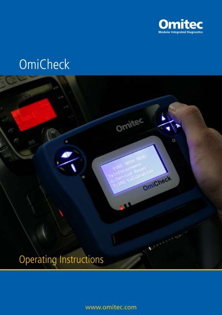
OmiCheck<br />
<strong>Operating</strong> <strong>Instructions</strong><br />
www.omitec.com
Part Number I319590<br />
EN - Issue 1<br />
OmiCheck<br />
<strong>Scan</strong> <strong>Tool</strong><br />
<strong>Operating</strong> <strong>Instructions</strong><br />
Part Number I??????<br />
EN<br />
Issue 1<br />
© Omitec 2010<br />
© Omitec 2010
Contents<br />
Introduction<br />
Overview................................................................................................. 1<br />
Kit Contents ............................................................................................ 2<br />
Keypads.................................................................................................. 3<br />
Connection ............................................................................................. 4<br />
Applications ............................................................................................ 5<br />
Safety Precautions ................................................................................. 6<br />
Getting Started ....................................................................................... 7<br />
General Information................................................................................ 9<br />
EOBD<br />
What is EOBD? .................................................................................... 11<br />
Identifying Compliant Vehicles ............................................................. 12<br />
Diagnostic Trouble Codes .................................................................... 13<br />
Interpreting EOBD Fault Codes............................................................ 14<br />
Using OmiCheck................................................................................... 15<br />
FastCheck<br />
Introduction........................................................................................... 21<br />
Safety <strong>Instructions</strong> ................................................................................ 22<br />
ABS (Anti-lock Braking System) ........................................................... 24<br />
Airbag ................................................................................................... 27<br />
Climate ................................................................................................. 31<br />
EPB (Electronic Parking Brake)............................................................ 33<br />
SAS (Steering Angle Sensor) ............................................................... 49<br />
Service.................................................................................................. 53<br />
TPMS (Tyre Pressure Monitoring System)........................................... 69<br />
i
Contents<br />
Manufacturer Applications<br />
General................................................................................................. 77<br />
Audi, Seat, Skoda and Volkswagen ..................................................... 78<br />
BMW................................................................................................... 194<br />
Citroen and Peugeot........................................................................... 194<br />
Fiat, Alfa and Lancia........................................................................... 210<br />
Ford .................................................................................................... 215<br />
GM Opel/Vauxhall .............................................................................. 231<br />
Honda ................................................................................................. 233<br />
Land Rover ......................................................................................... 237<br />
Mercedes............................................................................................ 244<br />
MG Rover ........................................................................................... 245<br />
Mitsubishi............................................................................................ 247<br />
Nissan................................................................................................. 249<br />
Renault ............................................................................................... 250<br />
User Menu<br />
Overview............................................................................................. 255<br />
Security............................................................................................... 258<br />
Appendix A: Glossary<br />
Glossary of terms ............................................................................... 260<br />
Appendix B: Cables<br />
Cable Identification ............................................................................. 267<br />
Appendix C: Diagnostic Connector Locations<br />
Diagnostic Connector Locations......................................................... 271<br />
ii
Contents<br />
Appendix D: Manual Service Reset<br />
Service Reminder Indicator (SRI)....................................................... 285<br />
Alfa Romeo......................................................................................... 285<br />
Audi .................................................................................................... 286<br />
BMW................................................................................................... 287<br />
Citroen ................................................................................................ 289<br />
Fiat...................................................................................................... 296<br />
Ford .................................................................................................... 297<br />
GM Vauxhall/Opel .............................................................................. 298<br />
Lancia ................................................................................................. 299<br />
Land Rover ......................................................................................... 300<br />
Mercedes............................................................................................ 301<br />
Peugeot .............................................................................................. 302<br />
Renault ............................................................................................... 308<br />
Smart .................................................................................................. 313<br />
Volkswagen ........................................................................................ 314<br />
Volvo................................................................................................... 315<br />
iii
Introduction<br />
Overview<br />
1<br />
Introduction<br />
All new road vehicles and many older vehicles are fitted with one or more control<br />
modules that monitor and control aspects of the vehicle, e.g. Engine, Transmission,<br />
ABS, Airbag etc.<br />
OM1563<br />
The OmiCheck is a scan tool that connects to the vehicle's control modules via the<br />
diagnostic socket and enables the operator to extract information from the various<br />
modules. For instance fault codes and live data plus other data and functions<br />
supported by the control module.<br />
The OmiCheck is supplied with the software to interrogate vehicle systems that<br />
conform to the European On-board Diagnostics (EOBD) standard. The EOBD<br />
standard is designed to extract emissions related data from the power train system of<br />
the vehicle. This will be the engine controller, of which there may be more than one,<br />
and the transmission controller if this is electronically controlled.<br />
Other test applications are available for non-EOBD systems and a number may be<br />
loaded on to the OmiCheck along with the EOBD application.<br />
It is recommended that a first time user reads through these instructions and safety<br />
guidelines and becomes familiar with the layout and content prior to commencing any<br />
testing on a vehicle.
Introduction<br />
Kit Contents<br />
The OmiCheck is available in two different configurations, Service and Professional.<br />
Although the same components are supplied in both kits, the software is different<br />
between the two.<br />
OmiCheck Service and Professional kit contents<br />
The basic kit includes:<br />
1. OmiCheck.<br />
2. J1962 cable.<br />
3. USB cable.<br />
4. CD ROM.<br />
1<br />
OM1569<br />
2<br />
2<br />
3<br />
4
Keypads<br />
The OmiCheck is operated via the two keypads.<br />
Left-hand keypad<br />
Key Function<br />
Scrolls left and right.<br />
Right-hand keypad<br />
Provides context sensitive help (where available).<br />
Key Function<br />
Scrolls up within a menu or text.<br />
Scrolls down within a menu or text.<br />
Selects a menu option, Continue or Yes.<br />
Exits a menu or No.<br />
OM1571<br />
OM1570<br />
3<br />
Introduction
Introduction<br />
Connection<br />
1<br />
OM1568<br />
2<br />
1. 25- way D-type diagnostic connector socket<br />
The diagnostic lead connector is located on the bottom edge of the OmiCheck,<br />
and is used to connect the appropriate vehicle communications cable to the<br />
OmiCheck. See ‘Cables’, page 267.<br />
NOTE: Always secure the diagnostic cable with the fixing screws to prevent<br />
accidental disconnection of the tester during use.<br />
2. USB connector socket<br />
The USB connector socket is located on the bottom edge of the OmiCheck, and<br />
is used to connect to a PC to download software updates.<br />
4
Applications<br />
The OmiCheck can be used in two ways:<br />
Stand-alone Module<br />
5<br />
Introduction<br />
As a stand-alone module, the OmiCheck can read live data, and is able to read and<br />
clear DTCs. Power for the OmiCheck is supplied via the diagnostic connector and<br />
therefore does not require a separate power supply.<br />
Download Mode<br />
OM1566<br />
OM1565<br />
The OmiCheck can be used away from the vehicle to download software updates.
Introduction<br />
Safety Precautions<br />
The following guidelines are intended to ensure the safety of the operator whilst<br />
preventing damage to the electrical and electronic components fitted to the vehicle.<br />
Equipment - prior to commencing any test procedure on the vehicle, ensure that the<br />
tester, its harnesses and connectors are in good condition.<br />
Polarity - always observe the correct polarity when connecting the tester to the vehicle<br />
battery.<br />
Before carrying out testing on a vehicle, the following procedure should always be<br />
observed:<br />
• Check the handbrake/parking brake is on.<br />
• Check that neutral or park is selected.<br />
• Keep test equipment and harnesses away from HT leads.<br />
• Be aware of moving engine parts.<br />
• Do not run engine in a confined space without adequate ventilation.<br />
6
Getting Started<br />
7<br />
Introduction<br />
Power for the OmiCheck is provided by the vehicle's diagnostic connector. Once<br />
connected, the message “System Configuration. Please Wait...” appears briefly on<br />
the OmiCheck's display before displaying the current software version number.<br />
Unlocking New Units<br />
A new or updated OmiCheck requires a security code to unlock the specific<br />
applications. To register the OmiCheck and to obtain your security code, call the<br />
Product Support Team on +44 (0)844 665 7681 or complete the activation form and<br />
Fax to +44 (0)844 665 7605 or email support@omitec.com.<br />
You will require your serial number (located on the back of the unit) and product key<br />
(located on the front of the CD wallet).<br />
After obtaining your security code, follow this procedure to unlock your OmiCheck.<br />
1. Select ‘User Menu’ from the main menu.<br />
2. Select ‘Security’ from the user menu.<br />
3. Select ‘Enter Security Key’ from the security menu.<br />
4. Using the and keys, scroll through the alpha/numerical character list.<br />
5. Confirm each character by pressing the key.<br />
If you make a mistake use the key and enter the correct character. To<br />
re-enter the code from the beginning, press the key.<br />
6. When prompted to verify the security key, press to confirm.<br />
7. Power down the OmiCheck by disconnecting the power source.<br />
8. Reconnect the power supply to restart the OmiCheck. The screen should now<br />
show EOBD and a list of the applications included.<br />
Unlocked Unit<br />
When unlocked the main menu for the OmiCheck will be displayed listing all the<br />
applications available on your OmiCheck.<br />
NOTE: The applications listed in the MAIN MENU are dependent on the level of<br />
OmiCheck purchased. Extra applications can be purchased separately. For further<br />
details, please consult your distributor.<br />
9. Use the and keys to select the required menu function.<br />
Press to confirm the selection.
Introduction<br />
Troubleshooting<br />
Problem Check:<br />
Communication problems between<br />
OmiCheck and vehicle.<br />
NOTE: Typical message is "Data Link<br />
Error"<br />
Communication problems between<br />
OmiCheck and PC.<br />
NOTE: Typical messages are "No<br />
reply…Trying again" and "Comms Lost<br />
Check Cable".<br />
If communications still cannot be established, contact the Product Support desk for<br />
further assistance.<br />
8<br />
• Check application list for vehicle<br />
coverage and harness used (including<br />
switch settings if applicable).<br />
• Check correct system was selected<br />
from the OmiCheck menu.<br />
• Vehicle connectors are free from<br />
grease.<br />
• Connectors for bent or missing pins<br />
• Connections fully mate.<br />
• If cable requires external power from<br />
the battery.<br />
• Vehicle immobiliser is disabled.<br />
• Control module is fully reset by turning<br />
ignition off, waiting 30 seconds then<br />
turning ignition back on before retrying<br />
comms.<br />
• The OmiCheck is powered from a 12V<br />
dc power supply unit supplied or<br />
vehicle.<br />
• COM Port configuration is correct i.e.<br />
set to the COM Port that the unit is<br />
connected to.<br />
• If serial to USB drivers are installed (if<br />
required).
General Information<br />
Cleaning<br />
9<br />
Introduction<br />
To maintain the condition and serviceability of the OmiCheck, it is advisable to follow<br />
the cleaning procedures below<br />
WARNING: Do not use solvents such as petroleum based cleaning agents,<br />
acetone, petrol, trichlorethylene etc. These types of harsh solvent may<br />
seriously damage the plastic casing. Do not even spray or pour this type of<br />
cleaner onto a cleaning cloth.<br />
WARNING: The OmiCheck is not waterproof. Always dry the unit thoroughly<br />
after cleaning or if it has been subject to accidental spillage.<br />
The manufacturer recommends that you periodically inspect and clean the following<br />
parts of the OmiCheck:<br />
• Case<br />
• Display screen<br />
• Keypad<br />
• Adaptor cables and connectors<br />
To clean the OmiCheck, or any of its cables or connectors, apply a mild detergent<br />
solution to a soft clean cloth that has been suitably dampened.<br />
WARNING: Before cleaning, disconnect the OmiCheck from the vehicle.<br />
Display Screen<br />
During normal everyday use, the screen may become dusty or covered in grime. To<br />
clean the screen, always use a soft, clean, antistatic cloth. If any stubborn stains or<br />
marks remain, use a non-abrasive glass cleaner applied to a soft, clean cloth. Gently<br />
wipe the cloth across the display until the marks have been removed.
Introduction<br />
Specification<br />
OmiCheck complies with ISO/DIS 15031 Part 4 as an EOBD OmiCheck<br />
Voltage requirements - 8.0 Volts to 16.0 Volts DC<br />
Current requirement - 750mA max<br />
Display - 20 characters by 4 lines LCD with LED back light<br />
<strong>Operating</strong> Temperature range - 0°C to 50°C<br />
Declaration of Conformity<br />
The OmiCheck is CE marked and complies with the following directives:<br />
EN55022:1998 - ITE Emissions di(Class A)<br />
EN50082-1:1998 - Generic EMC Immunity<br />
EN60950:1992 - Safety Requirements<br />
FCC47 Part 15 - Radio Frequency Devices (Class A)<br />
A copy of the Declaration of Conformity certificate is available on request from the<br />
manufacturer or your supplier.<br />
10
EOBD<br />
What is EOBD?<br />
11<br />
EOBD<br />
The American Environmental Protection Agency and the European parliament have<br />
set targets for reducing the levels of pollution produced by passenger and commercial<br />
vehicles. In order to ensure that these targets can be met, manufacturers are required<br />
to build new vehicles which meet increasingly stiff emissions standards. The<br />
manufacturers must further maintain these emission standards for the useful life of<br />
the vehicle. In order to meet and maintain these standards the vehicles are fitted with<br />
On-Board Diagnostic systems which monitor the integrity and effectiveness of all<br />
emission related components.<br />
As vehicles are becoming more and more complex, many of the systems fitted to<br />
them are being controlled by electronic control modules. Most vehicles now have<br />
multiple control modules (e.g. Engine, Transmission, Body, Suspension, etc.) located<br />
at different locations on the vehicle. The On-Board Diagnostic systems are integrated<br />
into the vehicle control modules.<br />
With so many different vehicle and component manufacturers, a common interface<br />
was required to communicate with these control modules. In 1988, the SAE (Society<br />
of <strong>Automotive</strong> Engineers) created a standard that defined a standard diagnostic<br />
socket (J1962) and a set of diagnostic test signals.<br />
With the diagnostic socket and diagnostic signals agreed, another standard was<br />
produced that defined a universal inspection and diagnosis method to ensure that a<br />
vehicle is performing to Original Equipment Manufacturer (OEM) specifications. This<br />
standard is known as EOBD (European On-Board Diagnostics).<br />
The fundamental requirement for an EOBD system is that in the event of an emissions<br />
related component fault, a DTC (Diagnostic Trouble Code) will be stored in the<br />
memory of the control module responsible for that component, and a Malfunction<br />
Indicator Lamp (MIL) will illuminate on the vehicle's instrument pack to alert the driver.<br />
The DTC can then be retrieved using diagnostic equipment to determine the type and<br />
status of the fault.
EOBD<br />
Identifying Compliant Vehicles<br />
All petrol engine vehicles manufactured since 2000 should be EOBD compliant.<br />
Some manufacturers began incorporating On-Board Diagnostic systems as early as<br />
1994, however not all are 100% compliant. All diesel engine vehicles are expected to<br />
have support from 2004. This means that diagnostic information, related to vehicle<br />
emissions, may be extracted from the vehicle via the J1962 diagnostic socket using<br />
the OmiCheck.<br />
The OmiCheck can communicate with any EOBD compliant vehicle using one of the<br />
five diagnostic communication protocols defined in the standard.<br />
These are<br />
• ISO 9141<br />
• Keyword 2000 (originally a European protocol)<br />
• J1850 PWM (pulse width modulated) protocol used by Ford<br />
• J1850 VPW (variable pulse width modulated) used by General Motors in USA<br />
designed vehicles<br />
• CAN (controller area network) currently being legislated for and likely to be a<br />
principle diagnostic communication system in the future. A European protocol.<br />
It is normally possible to tell which is used on a specific vehicle by examining the<br />
diagnostic socket (as below), however the OmiCheck's software will automatically<br />
detect the protocol used on the vehicle to which it is connected.<br />
16<br />
8<br />
OM1038<br />
9<br />
1<br />
• If the diagnostic socket has a pin in the ‘7’ or ‘15’<br />
position, then the vehicle uses either the ISO<br />
9141 or Keyword 2000 protocol.<br />
• If the diagnostic socket has a pin in the ‘2’ or ‘10’<br />
position, then the vehicle uses one of the SAE<br />
J1850 protocols.<br />
• If the diagnostic socket has a pin in the ‘6’ or ‘14’<br />
position, then the vehicle uses the CAN<br />
protocol.<br />
NOTE: Although there are different EOBD electrical connection protocols, the<br />
command set is fixed according to the SAE J1979 standard.<br />
12
Diagnostic Trouble Codes<br />
13<br />
EOBD<br />
Diagnostic Trouble Codes (DTCs) are divided into mandatory and voluntary codes.<br />
Mandatory codes are allocated by the ISO (International Standards Organisation)/<br />
SAE (Society of <strong>Automotive</strong> Engineers). Voluntary codes are allocated by various<br />
vehicle manufacturers and are manufacturer specific and in some instances, vehicle<br />
specific.<br />
ISO/SAE controlled diagnostic trouble codes are those codes where industry<br />
uniformity has been achieved. These codes were felt to be common enough across<br />
most manufacturer's applications that a common number and fault message could be<br />
assigned. All unspecified numbers in each grouping have been reserved for future<br />
growth. Although service procedures may differ widely amongst manufacturers, the<br />
fault being indicated is common enough to be assigned a particular fault code. Codes<br />
in this area are not to be used by manufacturers until they have been approved by<br />
ISO/SAE.<br />
Areas within each of the fault code blocks have been allocated for manufacturer<br />
controlled DTCs. These are fault codes that will not generally be used by the majority<br />
of the manufacturers due to basic system, implementation, or diagnostic strategy<br />
differences.
EOBD<br />
Interpreting EOBD Fault Codes<br />
Use the following rules to determine the basic meaning of an EOBD fault code.<br />
P Powertrain<br />
B Body<br />
C Chassis<br />
U Network<br />
The first character indicates which area of the vehicle the code applies to.<br />
0 Standard (SAE) code<br />
1 Manufacturer's own code<br />
The second character specifies the type of code:<br />
1 Fuel and air metering<br />
2 Fuel and air metering, specifically injector circuit<br />
3 Ignition system and misfire detection<br />
4 Auxiliary emission controls<br />
5 Vehicle speed control and idle control system<br />
6 Computer output circuit<br />
7 Transmission related faults<br />
8 Transmission related faults<br />
If the first character was 'P' (Powertrain) then the third character identifies the specific<br />
Powertrain system concerned:<br />
The last two characters identify the specific fault as seen by the on-board systems.<br />
14
Using OmiCheck<br />
Connection and Basic Operation<br />
1. Connect cable (SB100/10) to the OmiCheck and secure the fixing screws.<br />
2. Ensure the vehicle's ignition switch is in the '0' position.<br />
16<br />
8<br />
OM1038<br />
J1962 Diagnostic socket<br />
15<br />
EOBD<br />
3. Connect the OmiCheck to the vehicle via the J1962 diagnostic socket. This<br />
socket is usually located inside the passenger compartment. Refer to vehicle<br />
manufacturers' information for the exact location.<br />
Power for the OmiCheck is provided by the diagnostic socket. When connected<br />
to the diagnostic socket, the OmiCheck will perform an internal self test and then<br />
the screen will display the date of the current software version before displaying<br />
the main menu.<br />
4. Use the and keys to select the EOBD menu function.<br />
Press to confirm the selection.<br />
5. Turn the ignition on when prompted, then press the key to confirm. The<br />
OmiCheck will then attempt to establish communication with the vehicle's<br />
On-Board Diagnostics.<br />
If the vehicle system is not EOBD compliant or there is a connection problem, the<br />
"Please Wait" screen will be replaced with help screens.<br />
If communication with the On-Board Diagnostics is successful, then the display<br />
will report that the OmiCheck is checking the vehicle's Inspection/Maintenance<br />
(I/M) Readiness tests.<br />
NOTE: The vehicles ignition MUST be on for successful communication with the<br />
vehicle control modules.<br />
6. The tester checks to see which of the I/M Readiness tests have been run and<br />
successfully completed and then the screen will inform you of the status. Press<br />
the key to continue.<br />
NOTE: The OmiCheck will always check the status of the I/M Readiness tests<br />
before displaying the EOBD Operations menu.<br />
7. The screen will then give you the option of viewing the status of the tests<br />
performed on the emission related systems and their components.<br />
Press the key to display the results.<br />
Press the key to bypass the results and go to the EOBD Operations menu.<br />
9<br />
1
EOBD<br />
1.<br />
EOBD OPERATIONS<br />
MIL Status<br />
2. View DTCs<br />
3. Erase DTCs<br />
4. Live Data<br />
5. O2 Sensor Tests<br />
6. View Freeze Frame<br />
7. Non-Continuous<br />
8. Continuous Tests<br />
9. System Control<br />
10. Vehicle Info<br />
11. OBD Status<br />
12. System Readiness<br />
13. Print Menu<br />
14. General Info<br />
15. Tester Setup<br />
8. Use the and keys to select the required function and press to confirm the<br />
selection.<br />
Easy Reset Facility<br />
To reset the OmiCheck without disconnecting from the vehicle, hold down the , ,<br />
& keys simultaneously.<br />
Menu Options<br />
Not all vehicle control modules will support all of the options available from the menu.<br />
If an option is not supported the OmiCheck will display either “Not supported” or “Not<br />
available”. This is a limitation of the software on the vehicle control modules and NOT<br />
a fault with the OmiCheck.<br />
MIL Status/MI Status<br />
'MIL Status' or 'MI Status' displays the status of the malfunction indicator lamp for<br />
each emissions related control module. If the status of the MIL is set to On, one or<br />
more DTCs will be stored in the vehicle's control modules and the instrument panel<br />
MIL will be illuminated.<br />
16
View DTCs<br />
17<br />
EOBD<br />
This option allows any 'Stored' or 'Pending' emission related DTCs (Diagnostic<br />
Trouble Codes) to be viewed. If any DTC is present, it will be displayed along with the<br />
identity of the Control Module (CM) that registered the fault.<br />
If more than one DTC is displayed, the required DTC can be selected by using the<br />
and keys. Press to select the DTC and display the description of the code.<br />
Dependent upon the DTC and the vehicle manufacturer, it may be necessary to select<br />
the manufacturer and possibly also the model of the vehicle to enable the correct<br />
description to be displayed. This setting will be retained while the OmiCheck is being<br />
used for EOBD operations but can be redefined or cleared under the 'Manufacturer'<br />
menu option.<br />
Erase DTCs<br />
This option will clear all 'Stored' and 'Pending' emission related DTCs, clear 'Freeze<br />
Frame' DTCs and associated data, clear Oxygen Sensor test data, clear<br />
'Non-Continuous' test results and reset the status of the 'System Readiness' tests on<br />
the control modules on the vehicle. The tester will then perform a 'Read DTCs'<br />
operation to verify that the DTCs have been erased.<br />
Live Data<br />
This option allows the user to view the current status of the emission system<br />
components on the vehicle and can provide a quick way of telling if a component is<br />
working correctly.<br />
The list of components monitored under 'Live Data' can vary between manufacturers<br />
and even between model.
EOBD<br />
O2 Sensor Tests<br />
EOBD has an optional mode for monitoring the oxygen sensor test results depending<br />
on the method used by the vehicle manufacturer to comply with the requirement for<br />
oxygen sensor monitoring. If the manufacturer does use this mode not all tests need<br />
to be supported. The tester will display the supported tests and the data associated<br />
with those tests e.g. Maximum sensor voltage for a test cycle (calculated).<br />
View Freeze Frame<br />
Freeze frame data is a snap-shot of live data that was stored in the control module at<br />
the moment a Diagnostic Trouble Code was recognised. If a number of faults<br />
occurred, then the freeze frame data stored is associated with the last fault to occur.<br />
The DTC that generated the freeze frame data is also displayed in the data.<br />
Non-Continuous<br />
Some vehicle systems are not monitored continuously during normal running<br />
conditions, e.g. catalysts and evaporative systems. These tests are manufacturer<br />
specific, so while the results of the test will be shown, the meaning of the results<br />
cannot.<br />
Continuous Tests (Pending DTCs)<br />
When the 'continuous monitor' detects a failure condition in an emission-related<br />
powertrain component or system, only once in a drive cycle, it stores a 'Pending' code<br />
in the control module's memory. If the continuous monitor detects the same failure<br />
condition during the next drive cycle, it registers a DTC and illuminates the MIL.<br />
System Control<br />
Components on the vehicle may be turned on and off, or pulsed to test their operation.<br />
These tests are manufacturer specific and are currently seldom supported in<br />
controllers.<br />
Vehicle Info<br />
Information is displayed relating to the vehicle. This may be the VIN, controller version<br />
numbers etc., but is not supported by all vehicles.<br />
OBD Status<br />
Indicates to the user whether or not the controller supports OBD requirements. Not all<br />
vehicles support this.<br />
18
System Readiness<br />
19<br />
EOBD<br />
When the ignition is turned on at the start of a test, the controller performs a number<br />
of tests on the system. If the conditions are not correct for the controller to perform<br />
the test e.g. if the engine is too cold, "Not Ready" status will be reported. Readiness<br />
test status is also offered for inspection after communications have been established.<br />
These may be reviewed or ignored until later.<br />
The tester allows the user to do continual reads of the status of the System Readiness<br />
tests i.e. whether the test is not supported, waiting to complete or has completed. This<br />
status can help a technician verify a repair in that they can check that the readiness<br />
tests that may have generated a DTC have run to completion. The following sub menu<br />
will let the user display the results in two ways.<br />
The option ‘Show As A List’ will give the user the options of 'DTCs Last Cleared' and<br />
'Current Drive Cycle'. The selection 'DTCs Last Cleared' is normally found on all<br />
EOBD vehicles and shows the status since the last clearing of DTCs, but it may not<br />
be valid for the current drive cycle. The option 'Current Drive Cycle' will display the<br />
status of the tests for the current drive cycle, but this is rarely supported on vehicles<br />
at this time.<br />
The option 'All On One Screen’ will show an abbreviated text version of the status for<br />
all the tests since 'DTCs Last Cleared'.<br />
In both cases the tester is continually updating the status displayed for each test.<br />
Tester Setup<br />
1.<br />
SYSTEM READINESS<br />
Show As A List<br />
2. All On One Screen<br />
This allows the user to select the units displayed in Live Data and Freeze Frame from<br />
either metric or imperial. The user may also select from abbreviated text or full text<br />
phrases. For more information, see ‘Tester Setup’, page 256.
EOBD<br />
Main Menu Availability<br />
Manufacturer Specific Applications<br />
WARNING: It is recommended that you obtain an updated security key from the<br />
Product Support team before updating the software in your OmiCheck unit as<br />
the new software may not work with an old version key.<br />
The OmiCheck is delivered with a range of Manufacturer Specific Applications<br />
already installed, although some may not be turned on. To turn on an application, a<br />
"key" is required from Omitec. When the application pack is purchased, the purchaser<br />
will receive instructions for the application and information on how the application may<br />
be enabled along with harnesses that may be required for the manufacturer range.<br />
To enter the security key scroll up in the 'Main Menu', select 'User Menu' and then<br />
'Security', finally select 'Enter Key'.<br />
Enter Key<br />
When an application/upgrade is purchased, the application pack instructs the user on<br />
how to obtain the Security Key to turn on the application. The following keypad<br />
buttons are used to enter the key.<br />
& Scrolls through the possible characters to be used in the key.<br />
Accepts the character selected and advances to the next character<br />
location.<br />
Exits the change key function without saving the key.<br />
Moves backward through the key in the event of an error.<br />
Show Key<br />
Displays the current key that has been programmed into the OmiCheck. This controls<br />
the applications that are available to the user. The key is an alphanumeric code of 15<br />
or 20 characters.<br />
Software Version<br />
The software version of each of the applications installed is displayed. This<br />
information is likely to be required in the event of the user contacting the help desk.<br />
This menu item also informs the user what applications are installed if all have not<br />
been purchased.<br />
20
FastCheck<br />
Introduction<br />
21<br />
FastCheck<br />
The ‘FastCheck’ applications allow the OmiCheck to communicate with other system<br />
control modules on the vehicle, in addition to the standard emission related On-Board<br />
Diagnostic (OBD) functionality.<br />
There are currently seven applications that can be selected from the main menu.<br />
• ABS<br />
• Airbag<br />
• Climate<br />
• EPB<br />
• SAS<br />
• Service<br />
• TPMS<br />
The ‘ABS’, ‘Airbag’ and ‘Climate’ applications allow you to read and clear any fault<br />
codes stored by the selected system.<br />
The 'EPB' (Electronic Parking Brake) function allows you to read and clear any fault<br />
codes stored by the selected system and in addition can be used during brake<br />
operation checks or brake pad replacement.<br />
The 'SAS' (Steering Angle Sensor) allows you to read and clear any faults codes<br />
stored by the selected system, and in addition can be used to calibrate the steering<br />
angle sensor.<br />
The ‘Service’ application allows you to reset, dependent upon vehicle, the oil service<br />
interval indicator, service and inspection warning lights.<br />
The 'TPMS' (Tyre Pressure Monitoring System) function can be used to re-program<br />
tyre valves on vehicles fitted with Schrader TPMS valves.<br />
Connection to the specific system is via either the vehicle's J1962 diagnostic socket<br />
or by a system specific connector. Refer to the 'Vehicle Application List' to determine<br />
the correct connection point and interface cable.
FastCheck<br />
Safety <strong>Instructions</strong><br />
WARNING: General Safety<br />
• All operations must be carried out in a well ventilated area away from open<br />
flame and heat sources.<br />
• Ensure the vehicle is stationary and the handbrake (parking brake) is applied<br />
before carrying out any maintenance/diagnostic work.<br />
WARNING: Air Conditioning Safety<br />
• Servicing must only be carried out if you are familiar with both the vehicle<br />
system and the test equipment.<br />
• Air conditioning refrigerant is a hazardous liquid and when handled<br />
incorrectly can cause serious injury. Suitable protective clothing, consisting<br />
of face protection, heat proof gloves, rubber boots and rubber apron or<br />
waterproof overalls, must be worn when carrying out operations on the air<br />
conditioning system.<br />
• Danger of asphyxiation, refrigerant gas is heavier than air and will collect in<br />
vehicle inspection pits or confined spaces, always recover all refrigerant<br />
from a damaged system before commencing work.<br />
WARNING: Airbag Safety<br />
• All work on vehicle restraint systems should be carried out by trained<br />
personnel. NEVER install accessories in the vicinity of driver, passenger or<br />
side airbags.<br />
• Observe component manufacturers instructions for safety, handling and<br />
installation of components.<br />
• Airbags are classed as explosive devices and as such are subject to national<br />
laws which must be followed. This includes storage and transportation.<br />
• ALWAYS store removed airbags in a secure area away from other hazardous<br />
materials.<br />
• DO NOT connect or disconnect any wiring with the ignition ON. ALWAYS<br />
turn the ignition switch to the 'OFF' position and allow at least 1 minute for<br />
the system to discharge.<br />
• NEVER expose system components to temperatures above 176°F (80°C).<br />
• ONLY use approved diagnostic testers to diagnose faults, NEVER use<br />
multi-meters or test lamps etc.<br />
• ALWAYS disconnect all airbags and seat belt pre-tensionless before using<br />
a multi-meter to check the wiring.<br />
22
WARNING: EPB Safety<br />
23<br />
FastCheck<br />
• Ensure that you are fully familiar with the braking system and it's operation<br />
before commencing any work.<br />
• The Electronic Parking Brake Control system may be required to be<br />
deactivated before carrying out any Maintenance/diagnostic work on the<br />
brake system. This can be done from the OmiCheck menu.<br />
• Only carry out maintenance work when the vehicle is stationary and on level<br />
ground.<br />
• Ensure that the Electronic Parking Brake Control system is reactivated after<br />
the maintenance work has been completed.<br />
NOTE: Omitec Group accept no responsibility for any accident or injury arising from<br />
the maintenance of the Electronic Parking Brake system.
FastCheck<br />
ABS (Anti-lock Braking System)<br />
IMPORTANT INFORMATION<br />
Mercedes vehicles with Sensotronic Brake Control<br />
• Ensure that you are fully familiar with the braking system and it's operation before<br />
commencing any work.<br />
• The Sensotronic Brake Control system must be deactivated before carrying out any<br />
maintenance/diagnostic work on the brake system. This can be done from the<br />
OmiCheck menu.<br />
• Only commence work after the system has been deactivated. Upon deactivation, a<br />
warning message should appear in the instrument panel accompanied by an audible<br />
warning signal until the system is reactivated. If the warning signals do not occur,<br />
assume that the system is not fully deactivated and DO NOT commence work.<br />
• Ensure that the Sensotronic Brake Control system is reactivated after the<br />
maintenance work has been completed.<br />
NOTE: The manufacturer of the scan tool accept no responsibility for any accident or<br />
injury arising from the maintenance of the Sensotronic Brake Control system.<br />
Connection<br />
Using the Vehicle Application List on the CD-ROM, identify the required interface<br />
cable for the vehicle system to be tested. Connect the cable to the OmiCheck and<br />
secure the fixing screws.<br />
NOTE: If the vehicle being tested is a BMW with a 20 pin connector and an OBD-II<br />
connector, you must only use the 20 pin connector.<br />
Ensure the vehicle's ignition is OFF.<br />
Connect the OmiCheck to the required vehicle connector, refer to ‘Diagnostic<br />
Connector Locations’, page 271, for further information.<br />
Power for the OmiCheck is provided by the vehicle connector. Once connected, the<br />
OmiCheck will perform an internal self test and then the screen will display the date<br />
of the current software version before displaying the main menu.<br />
MAIN MENU<br />
1. EOBD<br />
2. FastCheck ABS<br />
3. FastCheck Airbag<br />
4. FastCheck Climate<br />
5. FastCheck EPB<br />
6. FastCheck SAS<br />
7. FastCheck Service<br />
8. FastCheck TPMS<br />
9. User Menu<br />
24
25<br />
FastCheck<br />
Use the and keys to select the 'ABS' application and press to confirm the<br />
selection. To return to the previous menu, press the<br />
Turn the vehicle's ignition ON.<br />
key.<br />
Use the<br />
selection.<br />
and keys to select the vehicle manufacturer and press to confirm the<br />
Dependent upon the vehicle and application being run, you may be asked to choose<br />
the particular system fitted to the vehicle. Select the correct system using the and<br />
keys and press to confirm.<br />
Select the required menu option using the and keys and press to confirm.<br />
The OmiCheck will attempt to establish communication with the vehicle system. If<br />
communication is unsuccessful, refer to ‘Troubleshooting’, page 8.<br />
Read DTCs<br />
1. Read DTCs<br />
2. Clear DTCs<br />
If any DTC codes are present in the system, a screen will be displayed informing you<br />
how many codes were found. This will then be replaced by the first DTC code. DTC<br />
codes are generated according to the vehicle and system manufacturer.<br />
DTC 1 - 38 Right Low<br />
Pressure Sensor<br />
Circuit Signal High{ }<br />
A typical DTC code<br />
The fault number is displayed first, followed by the DTC code. In this example the fault<br />
displayed is DTC number 38 - Right Low Pressure Sensor Circuit Signal High or Open<br />
Circuit. If the description text is too long to fit on the display, '[...]' appears in the<br />
bottom right corner of the screen. This indicates that the text can be scrolled using the<br />
and keys to view the rest of the description.<br />
To view the next DTC (if more than 1 was found), scroll to the end of the text and press<br />
the key.<br />
To return to the menu, scroll to the end of the text and press the key.
FastCheck<br />
Clear DTCs<br />
Diagnostic trouble codes can be cleared using the 'Clear DTCs' option. When using<br />
the option you will be prompted to turn the ignition off. Wait until prompted before<br />
switching the ignition back on.<br />
Start the engine to force the control module to run a system check. Verify that the<br />
code(s) have been cleared by selecting 'Read DTCs'.<br />
NOTE: Reading DTC(s) without first starting the engine will only confirm that the<br />
stored DTC(s) have been cleared. Faults may still be present in the system causing<br />
a DTC to be stored next time the engine is started.<br />
BMW Vehicles<br />
NOTE: To switch the ignition ON procedure for vehicles fitted with a start/stop, insert<br />
the remote key-fob fully into the ignition slot then press the start/stop button once<br />
(without any foot pedals depressed).<br />
26
Airbag<br />
27<br />
FastCheck<br />
Connection<br />
Using the Vehicle Application List on the CD-ROM, identify the required interface<br />
cable for the vehicle system to be tested. Connect the cable to the OmiCheck and<br />
secure the fixing screws.<br />
Ensure the vehicle's ignition is OFF.<br />
Connect the OmiCheck to the required vehicle connector, refer to ‘Diagnostic<br />
Connector Locations’, page 271, for further information.<br />
Power for the OmiCheck is provided by the vehicle connector. Once connected, the<br />
OmiCheck will perform an internal self test and then the screen will display the date<br />
of the current software version before displaying the main menu.<br />
MAIN MENU<br />
1. EOBD<br />
2. FastCheck ABS<br />
3. FastCheck Airbag<br />
4. FastCheck Climate<br />
5. FastCheck EPB<br />
6. FastCheck SAS<br />
7. FastCheck Service<br />
8. FastCheck TPMS<br />
9. User Menu<br />
Use the and keys to select the 'Airbag' application and press to confirm the<br />
selection. To return to the previous menu, press the<br />
Turn the vehicle's ignition ON.<br />
key.<br />
Use the<br />
selection.<br />
and keys to select the vehicle manufacturer and press to confirm the<br />
Dependent upon the vehicle and application being run, you may be asked to choose<br />
the particular system fitted to the vehicle. Select the correct system using the and<br />
keys and press to confirm.<br />
1. Read DTCs<br />
2. Clear DTCs<br />
Select the required menu option using the and keys and press to confirm.<br />
The OmiCheck will attempt to establish communication with the vehicle system. If<br />
communication is unsuccessful, refer to ‘Troubleshooting’, page 8.
FastCheck<br />
Read DTCs<br />
If any DTC codes are present in the system, a screen will be displayed informing you<br />
how many codes were found. This will then be replaced by the first DTC code. DTC<br />
codes are generated according to the vehicle and system manufacturer.<br />
The fault number is displayed first, followed by the DTC code. If the description text<br />
is too long to fit on the display, '[...]' appears in the bottom right corner of the screen.<br />
This indicates that the text can be scrolled using the and keys to view the rest<br />
of the description.<br />
To view the next DTC (if more than 1 was found), scroll to the end of the text and press<br />
the key.<br />
To return to the menu, scroll to the end of the text and press the key.<br />
Clear DTCs<br />
Diagnostic trouble codes can be cleared using the 'Clear DTCs' option. When using<br />
the option you will be prompted to turn the ignition off. Wait until prompted before<br />
switching the ignition back on.<br />
Verify that the code(s) have been cleared by selecting 'Read DTCs'.<br />
BMW Vehicles<br />
NOTE: To switch the ignition ON procedure for vehicles fitted with a start/stop, insert<br />
the remote key-fob fully into the ignition slot then press the start/stop button once<br />
(without any foot pedals depressed).<br />
Some BMW vehicles are equipped with multiple airbag systems, one for each airbag<br />
fitted to the vehicle.<br />
Applicable Vehicles:<br />
BMW 3 series (E90/E91/E92/E93)<br />
BMW 5 series (E60/E61)<br />
BMW 6 series (E63/E64)<br />
BMW 7 series (E65)<br />
BMW Z4 (E85)<br />
If on selecting the Read DTCs or Clear DTCs and a multiple airbag system is<br />
detected, then a menu containing a list of airbag systems fitted to the vehicle will be<br />
displayed.<br />
Use the and keys to select the required system from the menu shown. Press the<br />
key to select the system required the Read DTCs or Clear DTCs will be performed.<br />
Press the key while the system menu is displayed to return back to the Read DTCs<br />
and Clear DTCs menu.<br />
28
29<br />
FastCheck<br />
All airbag ECU’s<br />
If the All airbag ECU’s was selected then the Read DTCs or Clear DTCs function will<br />
be performed on ALL detected airbag systems on the vehicle.<br />
Ford Galaxy (2006 -), Mondeo (2007-), S-Max (2006-), Transit (2006-)<br />
Crash Reset<br />
This option is necessary on vehicles where airbags have been deployed following a<br />
crash. The routine clears the crash flag in the Body Control Module to enable normal<br />
operation after repair of the vehicle and installation of a new airbag.<br />
Land Rover Freelander 2 (2007-)<br />
Restraints Build Mode Entry/Exit<br />
This function can be used to place the Airbag/Restraint system in to build mode, to<br />
enable safe maintenance and repairs to be performed without risk of airbag or<br />
pretensioner detonation. When work has been completed on the system, the Airbag/<br />
Restraints system can be taken out of build mode to enable normal operation.<br />
Crash Reset<br />
This option is necessary on vehicles where airbags have been deployed following a<br />
crash. The routine clears the crash flag in the Body Control Module to enable normal<br />
operation after repair of the vehicle and installation of a new airbag.<br />
MINI vehicles<br />
NOTE: To switch the ignition ON for vehicles fitted with a start/stop button, insert the<br />
remote key-fob fully into the ignition slot then press the start/stop button once (without<br />
any foot pedals depressed).<br />
Renault vehicles<br />
Select the airbag system then select either 12-pin or 16-pin according to which<br />
connector is fitted to the vehicle under test.Then follow the on screen instructions.<br />
The following functions are available for the airbag system:<br />
1. Read DTCs: Displays all diagnostic trouble codes associated with the airbag<br />
system<br />
2. Clear DTCs: Clears all faults codes from the airbag system.<br />
3. Renault Arm/Disarm for Driver/Passenger Airbag:<br />
The Disarm CM (LOCK) menu option allows the driver airbag to be disabled<br />
preventing accidental deployment while working on the car.<br />
The Arm CM (UNLOCK) menu option causes the driver airbag to become active.
FastCheck<br />
The Disarm Passenger (LOCK) menu option allows the passenger airbag to be<br />
disabled preventing accidental deployment while working on the car.<br />
The Arm Passenger (UNLOCK) menu option causes the passenger airbag to become<br />
active.<br />
NOTE: Not all vehicles will have a passenger airbag and some vehicles with a<br />
passenger airbag cannot be armed/disarmed using a diagnostic tool (they require a<br />
key to be inserted into the arm/disarm lock located next to the passenger airbag).<br />
Vehicle notification methods for a locked airbag<br />
Method 1 - Fault Code present:<br />
If the user reads airbag diagnostic codes after an airbag has been locked some<br />
models will produce an 'Airbag locked' fault code. After unlocking, this fault code will<br />
not appear, this can be confirmed by reading the diagnostic codes again.<br />
Method 2 - Airbag MIL stays ON:<br />
After an airbag has been locked the Airbag Malfunction Indicator on the dash panel<br />
display will remain on, when the airbag is unlocked the MIL will switch off.<br />
Method 3 - Airbag MIL flashes for several seconds when turning the ignition on:<br />
After an airbag has been locked the Airbag Malfunction Indicator on the dash panel<br />
display will flash for several seconds when the ignition is turned on, when the airbag<br />
is unlocked the MIL will switch off.<br />
30
Climate<br />
31<br />
FastCheck<br />
Connection<br />
Using the Vehicle Application List on the CD-ROM, identify the required interface<br />
cable for the vehicle system to be tested. Connect the cable to the OmiCheck and<br />
secure the fixing screws.<br />
Ensure the vehicle's ignition is OFF.<br />
Connect the OmiCheck to the required vehicle connector, refer to ‘Diagnostic<br />
Connector Locations’, page 271, for further information.<br />
Power for the OmiCheck is provided by the vehicle connector. Once connected, the<br />
OmiCheck will perform an internal self test and then the screen will display the date<br />
of the current software version before displaying the main menu.<br />
MAIN MENU<br />
1. EOBD<br />
2. FastCheck ABS<br />
3. FastCheck Airbag<br />
4. FastCheck Climate<br />
5. FastCheck EPB<br />
6. FastCheck SAS<br />
7. FastCheck Service<br />
8. FastCheck TPMS<br />
9. User Menu<br />
Use the and keys to select the 'Climate' application and press to confirm the<br />
selection.To return to the previous menu, press the<br />
Turn the vehicle's ignition ON.<br />
key.<br />
Use the<br />
selection.<br />
and keys to select the vehicle manufacturer and press to confirm the<br />
Dependent upon the vehicle and application being run, you may be asked to choose<br />
the particular system fitted to the vehicle. Select the correct system using the and<br />
keys and press to confirm.<br />
1. Read DTCs<br />
2. Clear DTCs<br />
Select the required menu option using the and keys and press to confirm.<br />
The OmiCheck will attempt to establish communication with the vehicle system. If<br />
communication is unsuccessful, refer to ‘Troubleshooting’, page 8.
FastCheck<br />
Read DTCs<br />
If any DTC codes are present in the system, a screen will be displayed informing you<br />
how many codes were found. This will then be replaced by the first DTC code. DTC<br />
codes are generated according to the vehicle and system manufacturer.<br />
The fault number is displayed first, followed by the DTC code. If the description text<br />
is too long to fit on the display, '[...]' appears in the bottom right corner of the screen.<br />
This indicates that the text can be scrolled using the and keys to view the rest<br />
of the description.<br />
To view the next DTC (if more than 1 was found), scroll to the end of the text and press<br />
the key.<br />
To return to the menu, scroll to the end of the text and press the key.<br />
Clear DTCs<br />
Diagnostic trouble codes can be cleared using the 'Clear DTCs' option. When using<br />
the option you will be prompted to turn the ignition off. Wait until prompted before<br />
switching the ignition back on.<br />
Start the engine to force the control module to run a system check. Verify that the<br />
code(s) have been cleared by selecting 'Read DTCs'.<br />
NOTE: Reading DTC(s) without first starting the engine will only confirm that the<br />
stored DTC(s) have been cleared. Faults may still be present in the system causing<br />
a DTC to be stored next time the engine is started.<br />
BMW/MINI Vehicles<br />
NOTE: To switch the ignition ON procedure for vehicles fitted with a start/stop, insert<br />
the remote key-fob fully into the ignition slot then press the start/stop button once<br />
(without any foot pedals depressed).<br />
32
EPB (Electronic Parking Brake)<br />
33<br />
FastCheck<br />
Connection<br />
Using the Vehicle Application List, identify the required interface cable for the vehicle<br />
system to be tested. Connect the cable to the OmiCheck and secure the fixing<br />
screws.<br />
Ensure the vehicle's ignition is OFF.<br />
Connect the OmiCheck to the required vehicle connector, refer to ‘Diagnostic<br />
Connector Locations’, page 271, for further information.<br />
Power for the OmiCheck is provided by the vehicle connector. Once connected, the<br />
OmiCheck will perform an internal self test and then the screen will display the date<br />
of the current software version before displaying the main menu.<br />
MAIN MENU<br />
1. EOBD<br />
2. FastCheck ABS<br />
3. FastCheck Airbag<br />
4. FastCheck Climate<br />
5. FastCheck EPB<br />
6. FastCheck SAS<br />
7. FastCheck Service<br />
8. FastCheck TPMS<br />
9. User Menu<br />
Use the and keys to select the 'EPB' application and press to confirm the<br />
selection.To return to the previous menu, press the<br />
Turn the vehicle's ignition ON.<br />
key.<br />
Use the<br />
selection.<br />
and keys to select the vehicle manufacturer and press to confirm the
FastCheck<br />
Dependent upon the vehicle manufacturer and model different menu options will then<br />
be available. Function such as read and Clear DTCs will be available along with<br />
service functions.<br />
BMW vehicles<br />
NOTE: To switch the ignition ON for vehicles fitted with a start/stop button, insert the<br />
remote key-fob fully into the ignition slot then press the start/stop button once (without<br />
any foot pedals depressed).<br />
BMW 7 Series (E65)<br />
Parking Brake Bedding-in<br />
If the brake shoes of the ‘Duo Servo Brake’ are replaced then the bedding process<br />
must be performed to ensure correct operation of the system. The procedure may be<br />
performed on a roller test rig or on a road test drive.<br />
Automatic hold<br />
The Automatic hold function applies the brakes when the vehicle is stationary and<br />
applies the brakes and parking brake when the engine is switched off. This function<br />
can be disabled / enabled.<br />
Assembly mode<br />
Unintentional operation of the parking brake button before the Bowden cables have<br />
engaged in the wheel carrier can lead to assembly problems. Assembly mode<br />
suppresses the activation of the parking brake.<br />
Positioning travel check<br />
If excessive travel has been detected then a warning is displayed and fault stored.<br />
This procedure is used to determine the cause of the problem detected by the system.<br />
BMW X5 (E70) / X6 (E71)<br />
Workshop mode<br />
While in workshop mode the parking brake is placed into the opened position and the<br />
system is disabled.<br />
Parking Brake Bedding-in<br />
If the brake shoes of the ‘Duo Servo Brake’ are replaced then the bedding process<br />
must be performed to ensure correct operation of the system. The procedure may be<br />
performed on a roller test rig or on a road test drive.<br />
34
Ford – Electronic Parking Brake (EPB) System<br />
35<br />
FastCheck<br />
Two Electronic Parking Brake systems are currently supported on the service tool:<br />
Ford Focus C-Max 2003 - present:<br />
There are two test functions available under the calibration section of the EPB menu<br />
these are described below.<br />
Electronic Parking Brake Calibration Function Test<br />
Checks the Electronic Parking Brake is working correctly. This test should be<br />
performed after work has been completed on the Electronic Parking Brake or<br />
vehicles’ braking system.<br />
The test removes any air gap from the brake pads and checks the EPB pressure.<br />
Pre-Test conditions:<br />
• The vehicle must be stationary<br />
• The vehicle must be on level ground<br />
• The brake fluid level is correct<br />
The operator will be asked to perform a number of actions before applying the EPB.<br />
The OmiCheck reads and displays the EPB pressure. With the EPB applied the EPB<br />
pressure should be approximately 1100 Newtons.<br />
The operator will then be asked to unlock/release the EPB. The OmiCheck reads and<br />
displays the EPB pressure. With the EPB released the EPB pressure should be 0<br />
Newton.<br />
If either of the above tests fail (pressure reading not correct) the EPB assembly<br />
should be removed and re-assembled.<br />
Electronic Parking Brake Emergency Release Calibration<br />
Checks the Electronic Parking Brake emergency release is working correctly. This<br />
test should be performed after work has been completed on the Electronic Parking<br />
Brake or vehicles braking system.<br />
Pre-Test conditions:<br />
• The vehicle must be stationary<br />
• The vehicle must be on level ground<br />
• The brake fluid level is correct
FastCheck<br />
The operator will be asked to perform a number of actions before applying the EPB.<br />
The OmiCheck reads and displays the EPB pressure. With the EPB applied the EPB<br />
pressure should be approximately 1100 Newtons.<br />
The operator will then be prompted to pull manually on the emergency release. The<br />
OmiCheck reads and displays the EPB pressure. With the emergency release<br />
activated the EPB pressure should be 0 Newton and the vehicle should be able to<br />
move freely.<br />
If either of the above tests fail then the EPB assembly should be inspected and<br />
repaired as described by the manufacturer’s instructions.<br />
Ford Galaxy (2006-), Mondeo (2007-), S-Max (2006-):<br />
There are three options in the PBM/EPB function menu which can be used to access<br />
various functions:<br />
Service Brakes<br />
There are three functions available under the ‘Service Brakes’ menu option:<br />
Enter Maintenance Mode<br />
This function is used to put the system into a state that enables work to be carried out<br />
by the technician.<br />
The Control Module puts the calipers into a state where normal operation is inhibited<br />
and the callipers can not be closed by any means.This function must be used if<br />
replacement of the brakes, discs or brake pads is to be carried out.<br />
Pre-Test conditions:<br />
• The vehicle must be stationary<br />
• The vehicle must be on level ground<br />
• The vehicle must be secured with wheel locks<br />
This function takes 30 seconds to complete.<br />
NOTE: After this function has been performed the EPB calipers can not be closed and<br />
are inhibited until exit maintenance mode is run. Cycling the ignition, disconnecting<br />
the battery or diagnostics tester does not exit maintenance mode.<br />
Ensure the on screen instructions on the service tool are followed precisely and in the<br />
correct order.<br />
Exit Maintenance Mode<br />
This function is used to put the system back into an operational state after work has<br />
been carried out by the technician. Calipers are closed to the applied position, and<br />
normal operation is available again.<br />
36
37<br />
FastCheck<br />
Pre-Test conditions:<br />
• The vehicle must be stationary<br />
• The vehicle must be on level ground<br />
• The vehicle must be secured with wheel locks<br />
This function takes 35 seconds to complete.<br />
This function also automatically performs an 'Assembly Check', which carries out<br />
internal tests on the Parking Brake system and reports the status (see below). Ensure<br />
the on screen instructions on the service tool are followed precisely and in the correct<br />
order.<br />
Assembly Check<br />
This function is used to check the operation of the parking brake system after any<br />
work has been completed on the system.<br />
Pre-Test conditions:<br />
• The vehicle must be stationary<br />
• The vehicle must be on level ground<br />
• The vehicle must be secured with wheel locks<br />
This function takes 25 seconds to complete.<br />
NOTE: This test is automatically run as part of the 'Exit Maintenance Mode' function.<br />
It is not necessary to perform this function if the 'Exit Maintenance Mode' function<br />
reported no problems<br />
NOTE: This function can not be performed while the parking brake system is in<br />
maintenance mode. It should only be performed when the system is in normal<br />
operating mode.<br />
Ensure the on screen instructions on the service tool are followed precisely and in the<br />
correct order.<br />
Actuators<br />
The following is available under the ‘Actuators’ menu option:<br />
Static Apply<br />
This function is used to test the operation of the actuators which operate the calipers.<br />
This function closes the actuators to the nominal parking brake apply position.
FastCheck<br />
Pre-Test conditions:<br />
• The vehicle must be stationary<br />
• The vehicle must be on level ground<br />
• The vehicle must be secured with wheel locks<br />
It should be used if it is suspected that there is a fault with the Control Module, wiring,<br />
or the actuators (if the parking brake will not engage/disengage when manually<br />
operated).<br />
NOTE: This function can not be performed while the parking brake system is in<br />
maintenance mode. It should only be performed when the system is in normal<br />
operating mode.<br />
Configuration<br />
There are two functions available under the ‘Configuration’ menu option:<br />
Inclination Sensor Calibration<br />
This function is used to reset the stored zero value of the inclination sensor. It should<br />
be used when a new Parking Brake module has been fitted or a new Inclination<br />
sensor has been fitted.<br />
Pre-Test conditions:<br />
• The operator must NOT be inside the vehicle<br />
• The vehicle must be stationary<br />
• The vehicle must be on level ground<br />
• Ensure the vehicle is not subject to any vibration (closing boot, bonnet, etc)<br />
• The vehicle must be secured with wheel locks<br />
NOTE: This function cannot be performed while the parking brake system is in<br />
maintenance mode. It should be performed when the system is in normal operating<br />
mode.<br />
Clear Stored Clutch Engagement Point<br />
This function is used to reset the stored value of the clutch engagement point. It<br />
should be used when a new Parking Brake module has been fitted or a new clutch<br />
has been fitted. This function is only applicable to vehicles with manual transmission.<br />
38
39<br />
FastCheck<br />
Pre-Test conditions:<br />
• The vehicle must be stationary<br />
• The vehicle must be on level ground<br />
When this function has been performed successfully the Parking Brake module will<br />
re-learn a new clutch engagement point when the vehicle is next driven.<br />
NOTE: This function cannot be performed while the parking brake system is in<br />
maintenance mode. It should be performed when the system is in normal operating<br />
mode.<br />
Ensure the on screen instructions on the service tool are followed precisely and in the<br />
correct order.<br />
Notes on Use of Functions<br />
The four functions are designed to be used in several different situations. Here are a<br />
few situations which may occur and the correct use of the functions to rectify the<br />
situation:<br />
Rear Brake Pad, Brake Disc or Caliper Replacement:<br />
1. If the vehicle requires any of the above components to be replaced the 'Enter<br />
Maintenance Mode' function should be performed.<br />
2. The system will be disabled to allow maintenance work to be carried out easily<br />
and safely.<br />
3. After the work has been carried out the 'Exit Maintenance Mode' function should<br />
be performed.<br />
Inclination Sensor Replacement:<br />
1. After the new sensor has been installed perform the ‘Inclination Sensor<br />
Calibration’ function.<br />
Clutch Replacement (manual transmission):<br />
1. After a new clutch has been installed perform the ‘Clear Clutch Engagement<br />
Point’ function.<br />
2. The vehicle will then learn the new clutch engagement point as the vehicle is<br />
driven.<br />
Parking Brake Module Replacement:<br />
1. After the Parking Brake Module has been replaced perform the ‘Inclination<br />
Sensor Calibration’ function.<br />
2. If the vehicle has manual transmission perform the ‘Clear Clutch Engagement<br />
Point’ function.<br />
3. The vehicle will then learn the new clutch engagement point as the vehicle is<br />
driven.
FastCheck<br />
Any other EPB system component has been replaced:<br />
1. DTCs should be read and cleared.<br />
2. The 'Assembly Check' function should be performed to check the operation of the<br />
parking brake system.<br />
3. If the 'Assembly Check' function fails, DTCs should be read again and the<br />
problem investigated.<br />
The Parking Brake will not engage when manually operated via the button:<br />
1. Ensure that the system is NOT in 'Maintenance Mode'. If it is, then perform the<br />
'Exit Maintenance Mode' function.<br />
2. Read DTCs, there may be a DTC stored which will indicate the area of the fault.<br />
3. Clear DTCs, there may be an intermittent fault on the system which needs to be<br />
cleared.<br />
4. Perform the 'Static Apply' function. This will send a command directly to the<br />
Control Module which will then close the actuators to the nominal 'engaged'<br />
position.<br />
5. Check the switch/button.<br />
6. Check the actuators themselves or the wiring from the ‘Control Module’ to the<br />
actuators.<br />
Land Rover - Electronic Parking Brake (EPB) System<br />
Discovery III (L319) (2005 - 2009), Range Rover Sport (L320) (2005 -<br />
2009), Range Rover (L322) (2006 - 2009):<br />
There are four functions available under the PBM/EPB ‘Service Brakes’ menu:<br />
Unjam Electronic Parking Brake<br />
This procedure should be used if one of the Parking Brake cables becomes detached<br />
or breaks whilst the vehicle is being driven.<br />
Pre-Test conditions:<br />
• The vehicle must be stationary<br />
• The engine must be running and at idle speed<br />
After performing the procedure it is necessary for the technician to carry out checks<br />
on the condition of the rear brake shoes and drums. If both are OK the technician<br />
should then refer to the Land Rover technical information.<br />
NOTE: Part of this procedure is to place the Parking brake into ‘Mounting Position’; in<br />
order for the checks of the rear brake shoes and drums to be carried out. When the<br />
vehicle is in the 'Mounting Position' a red flashing light will appear on the instrument<br />
cluster. This indicates that the parking brake actuator is in the 'Mounting Position'. It<br />
does not indicate a vehicle fault.<br />
40
Mounting Position<br />
41<br />
FastCheck<br />
The park brake must be driven to the Mounting Position if any of the following<br />
procedures are to be performed:<br />
• Parking Brake Shoes - Removal/Installation.<br />
• Parking Brake Shoe and Lining Adjustment.<br />
This procedure must be carried out if, new parking brake shoes are fitted, new rear<br />
brake discs are fitted or if the vehicle has been mud wading (not water) for more<br />
than 50 miles. Or if one of the brake cables has broken or become detached during<br />
the vehicle being driven (in this case the Park brake is driven to the Mounting<br />
Position as part of the ‘Park Brake Unjam’ procedure above).<br />
• Changing of Parking Brake Cables (RH and LH).<br />
If the parking brake system has completed less than 50,000 cycles it is<br />
permissible to replace the parking brake cables. If over 50,000 cycles have been<br />
completed, then the cables can only replaced as part of the parking brake actuator<br />
and cable assembly. If a cable breaks or becomes detached whilst the vehicle is<br />
being driven, the 'parking brake unjam procedure' may be required.<br />
• Parking Brake Actuator - Removal/Installation<br />
The purpose is to allow the brake cables to be connected or disconnected to the<br />
brakes.<br />
Pre-Test conditions:<br />
• The vehicle must be stationary.<br />
• The ignition must be on (position II).<br />
• An approved battery charger must be connected to ensure consistent power<br />
supply.<br />
NOTE: To remove the parking brake from Mounting Position; switch the parking brake<br />
switch on and off twice.<br />
NOTE: When the vehicle is in the 'Mounting Position' a red flashing light will appear<br />
on the instrument cluster. This indicates that the parking brake actuator is in the<br />
'Mounting Position'. It does not indicate a vehicle fault.<br />
Ensure the on screen instructions on the service tool are followed precisely and in the<br />
correct order.
FastCheck<br />
Latching Position<br />
This procedure may be necessary if the Parking Brake emergency release has been<br />
activated, in order to re-latch the Parking brake.<br />
Pre-Test conditions:<br />
• The vehicle must be stationary.<br />
• The ignition must be on (position II).<br />
• An approved battery charger must be connected to ensure consistent power<br />
supply.<br />
Ensure the on screen instructions on the service tool are followed precisely and in the<br />
correct order.<br />
Longitudinal Accelerometer Calibration<br />
This procedure may be necessary if the Longitudinal Accelerometer has been<br />
replaced.<br />
Pre-Test conditions:<br />
• The ignition must be on (position II).<br />
• An approved battery charger must be connected to ensure consistent power<br />
supply.<br />
• Ensure the vehicle is placed on a level surface and that it remains stationary<br />
throughout the whole procedure.<br />
• Ensure the vehicle is stationary (0 km/h) on a level surface & no apply or release<br />
command has been received.<br />
• Make sure the parking brake module is correctly secured to the vehicle and that<br />
the parking brake is applied.<br />
Ensure the on screen instructions on the service tool are followed precisely and in the<br />
correct order.<br />
MANUAL FUNCTIONS<br />
The following can be performed manually without the OmiCheck:<br />
Disable Parking Brake for Rear Brake Disc Change<br />
This procedure is necessary before carrying out work on the rear brake discs. When<br />
performed correctly the brake callipers are wound back by the control module:<br />
Manual Routine:<br />
• Turn the ignition key to position II.<br />
• Apply, and hold, the footbrake,<br />
• Apply, and hold, the parking brake switch to the RELEASE position.<br />
42
43<br />
FastCheck<br />
• Turn the ignition key to position 0 and remove the key.<br />
• Release the footbrake.<br />
• Release the parking brake switch.<br />
• Remove fuse number 8 from the BJB (to isolate the parking brake electrical<br />
circuit).<br />
This will ensure safe working conditions and eradicate the threat of the parking brake<br />
accidentally coming on while the technician is working on it.<br />
To Re-enable Normal Operation:<br />
• Re-install fuse number 8 into the BJB (to re-enable the parking brake electrical<br />
circuit).<br />
Parking Brake Shoes Bedding-in Procedure<br />
This procedure must be carried out if, new parking brake shoes are fitted, new rear<br />
brake discs are fitted or if the vehicle has been mud wading (not water) for more than<br />
50 miles:<br />
Manual Routine:<br />
• Start and run the engine.<br />
• Apply the footbrake 3 times within 10 seconds and hold applied after the 3rd<br />
application.<br />
• Apply the electronic parking brake switch 4 times, followed by 3 release<br />
applications within 10 seconds.<br />
Once the Service Bedding-in procedure mode has been entered, the electronic<br />
parking brake linings can be bedded-in by conducting 10 repeated stops from 30<br />
- 35 km/h (19 - 22 mph), followed by a 500 metre (547 yard) interval between each<br />
stop to allow the brakes to cool, using the electronic parking brake control switch.<br />
• The electronic parking brake force will be increased up to the dynamic maximum<br />
so long as the switch is held in the applied position.<br />
• If the switch is released to either the NEUTRAL or OFF positions, the electronic<br />
parking brake will be released,<br />
• The electronic parking brake MUST be allowed to cool between applications,<br />
either by driving at 19 mph (30 km/h) for 500 metres (547 yards) or remaining<br />
stationary for 1 minute between each application.<br />
NOTE: The electronic parking brake 'Service Bedding-in Procedure mode' will be<br />
active for the remainder of the ignition cycle, or until the vehicle speed exceeds 31<br />
mph (50 km/h). If the procedure needs to be re-entered, the entry actions must be<br />
repeated.
FastCheck<br />
Renault - Handbrake<br />
There are test functions available under the circuit tests section of the handbrake<br />
menu these are described below.<br />
Release Brakes<br />
Pre-Test conditions:<br />
• The vehicle must be stationary<br />
• The vehicle must be on level ground<br />
• The engine must not be running<br />
The test requests the handbrake is released. The brakes will be released during this<br />
test once this test has been completed then the apply brakes function should be<br />
performed.<br />
Apply Brakes<br />
Pre-Test conditions:<br />
• The vehicle must be stationary<br />
• The vehicle must be on level ground<br />
• The engine must not be running<br />
The test requests the handbrake is applied. The brakes will be applied during this test.<br />
VAG – Electro-mechanic Parking Brake System<br />
VW/Audi Electro-mechanic Parking Brake (EPB) system integrates two<br />
electro-mechanical actuators (Right and Left Parking Brake Motors) into the rear disc<br />
brake callipers. The EPB system replaces the traditional handbrake system.<br />
When the vehicle is stationary or when the EPB/Auto hold button is pressed the EPB<br />
control module activates the parking bake motors on the rear wheels holding the<br />
vehicle in place.<br />
Pre-Test conditions:<br />
• The vehicle must be stationary<br />
• The vehicle must be on level ground<br />
• The brake fluid level is correct<br />
• The Parking brake is off<br />
NOTE: During the process of releasing and resetting the brake pistons the ECM may<br />
store DTCs in the EPB or ABS control modules. After completing the calibration<br />
procedure the EPB and ABS DTC memory must be cleared.<br />
44
EPB for Audi A4/A5/A6 & VW Passat/Tiguan<br />
45<br />
FastCheck<br />
Select the required option from the Maintenance menu either Replace Pads or<br />
Service Brakes then follow described sequence.<br />
Brake Pad Replacement/Service Sequence<br />
The EPB system must be deactivated and completely released and the ignition must<br />
be on.<br />
NOTE: The sequence must be performed in the correct order else the braking system<br />
maybe left in a non-operational state.<br />
Release Brakes<br />
Select the Release Brakes option from the menu. The brake pistons will now be<br />
moved to their released position. Wait until the OmiCheck displays the release brakes<br />
now complete message before continuing.<br />
Replace/Service the Brake Pads<br />
The brake pads can now be replaced or serviced following the manufacturer’s<br />
instructions.<br />
Close Brakes<br />
Select the Close Brakes option from the menu. The brake pistons will now be moved<br />
to their reset position. Wait until the OmiCheck displays the close brakes now<br />
complete message before continuing.<br />
Calibrate Brakes<br />
Select the Calibrate Brakes option from the menu. The brake pistons will now be<br />
moved in and out to calibrate their position. Wait until the OmiCheck displays the<br />
calibrate brakes now complete message before continuing.<br />
EPB for Audi A8<br />
Select the required option from the Maintenance menu either Replace Pads or<br />
Service Brakes then follow the required sequence.<br />
Brake Pad Replacement Sequence (Only)<br />
The EPB system must be deactivated and completely released and the ignition must<br />
be on then follow the sequence described below.<br />
NOTE: The sequence must be performed in the correct order otherwise the braking<br />
system maybe left in a non-operational state.
FastCheck<br />
Replace Pads<br />
Select the Replace Pads option from the Replace Pads menu. The brake pistons will<br />
now be moved to their released position. Wait until the OmiCheck displays the<br />
release brakes now open for pad change message before continuing.<br />
Replace the Brake Pads<br />
The brake pads can now be replaced following the manufacturer’s instructions.<br />
Pad Thickness<br />
The brake pad thickness must be now be entered by selecting Pad Thickness from<br />
the Replace Pads menu. The current value is displayed on screen. Press the key<br />
to change value then enter the new value between 3-14mm. Press the key to test<br />
the new value a message will be displayed. Press the key to move to the store new<br />
value screen. Now press the key again to store the new value to the control<br />
module.<br />
Close Brakes<br />
Select the Close Brakes option from the Replace Pads menu. The brake pistons will<br />
now be moved to their reset position. Wait until the OmiCheck displays the close<br />
brakes now complete message before continuing.<br />
Calibrate Brakes<br />
Select the Calibrate Brakes option from the Replace Pads menu. The brake pistons<br />
will now be moved in and out to calibrate their position. Wait until the OmiCheck<br />
displays the calibrate brakes now complete massage before continuing.<br />
Brakes Service Sequence (Only)<br />
The EPB system must be deactivated and completely released and the ignition must<br />
be on then follow the sequence described below.<br />
NOTE: The sequence must be performed in the correct order else the braking system<br />
maybe left in a non-operational state.<br />
Release Brakes<br />
Select the Release Brakes option from the Service Brakes menu. The brake pistons<br />
will now be moved to their released position. Wait until the OmiCheck displays the<br />
release brakes now complete message before continuing.<br />
Service the Brakes<br />
The brakes can now be serviced following the manufacturer’s instructions.<br />
46
Close Brakes<br />
47<br />
FastCheck<br />
Select the Close Brakes option from the Service Brakes menu. The brake pistons will<br />
now be moved to their reset position. Wait until the OmiCheck displays the close<br />
brakes now complete message before continuing.<br />
Calibrate Brakes<br />
Select the Calibrate Brakes option from the Service Brakes menu. The brake pistons<br />
will now be moved in and out to calibrate their position. Wait until the OmiCheck<br />
displays the calibrate brakes now complete massage before continuing.<br />
Volvo - Electronic Parking Brake (EPB) System<br />
Volvo S80 (2007 -), V70 (2008 -), XC60 (2009-), XC70 (2008 -)<br />
There are three options in the PBM/EPB function menu which can be used to access<br />
various functions:<br />
There are three functions available under the ‘Service Brakes’ menu option:<br />
Enter Service Mode<br />
This function is used to put the system into a state that enables work to be carried out<br />
by the technician. The Control Module puts the callipers into a state where normal<br />
operation is inhibited and the callipers cannot be closed by any means. This function<br />
must be used if replacement of the brakes, discs or brake pads is carried out.<br />
Pre-Test conditions:<br />
• The vehicle must be stationary<br />
• The vehicle must be on level ground<br />
• The vehicle must be secured with wheel locks.<br />
This function takes 30 seconds to complete.<br />
NOTE: After this function has been performed the EPB callipers cannot be closed and<br />
are inhibited until exit service mode is run. Cycling the ignition, disconnecting the<br />
battery or diagnostics tester does not exit maintenance mode.<br />
Ensure the on screen instructions on the service tool are followed precisely and in the<br />
correct order.
FastCheck<br />
Exit Service Mode<br />
This function is used to put the system back into an operational state after work has<br />
been carried out by the technician. Callipers are closed to the applied position, and<br />
normal operation is available again.<br />
Pre-Test conditions:<br />
• The vehicle must be stationary<br />
• The vehicle must be on level ground<br />
• The vehicle must be secured with wheel locks.<br />
This function takes 10 seconds to complete.<br />
Ensure the on screen instructions on the service tool are followed precisely and in the<br />
correct order.<br />
Installation Check<br />
This function is used to check the operation of the parking brake system after any<br />
work has been completed on the system.<br />
Pre-Test conditions:<br />
• The vehicle must be stationary<br />
• The vehicle must be on level ground<br />
• The vehicle must be secured with wheel locks.<br />
Three internal tests are performed, each will report the status. If any of these tests fail<br />
to perform the Read DTCs function to detect the possible fault with the system.<br />
This function takes 25 seconds to complete.<br />
NOTE: This function cannot be performed while the parking brake system is in service<br />
mode. It should only be performed when the system is in normal operating mode.<br />
Ensure the on screen instructions on the service tool are followed precisely and in the<br />
correct order.<br />
48
SAS (Steering Angle Sensor)<br />
49<br />
FastCheck<br />
Connection<br />
Using the Vehicle Application List on the CD-ROM, identify the required interface<br />
cable for the vehicle system to be tested. Connect the cable to the OmiCheck and<br />
secure the fixing screws.<br />
NOTE: If the vehicle being tested is a BMW with a 20 pin connector and an OBD-II<br />
connector, you must only use the 20 pin connector.<br />
Ensure the vehicle’s ignition is OFF.<br />
Connect the OmiCheck to the required vehicle connector, refer to ‘Diagnostic<br />
Connector Locations’, page 271, for further information.<br />
Power for the OmiCheck is provided by the vehicle connector. Once connected, the<br />
OmiCheck will perform an internal self test and then the screen will display the date<br />
of the current software version before displaying the main menu.<br />
MAIN MENU<br />
1. EOBD<br />
2. FastCheck ABS<br />
3. FastCheck Airbag<br />
4. FastCheck Climate<br />
5. FastCheck EPB<br />
6. FastCheck SAS<br />
7. FastCheck Service<br />
8. FastCheck TPMS<br />
9. User Menu<br />
Use the and keys to select the 'SAS' application and press to confirm the<br />
selection. To return to the previous menu, press the<br />
Turn the vehicle's ignition ON.<br />
key.<br />
Use the<br />
selection.<br />
and keys to select the vehicle manufacturer and press to confirm the<br />
Dependent upon the vehicle manufacturer and application being run, you may be<br />
asked to choose the particular system fitted to the vehicle. Select the correct system<br />
using the and keys and press to confirm.<br />
1. Read DTCs<br />
2. Clear DTCs<br />
3. SAS Calibration<br />
Select the required menu option using the and keys and press to confirm.
FastCheck<br />
The OmiCheck will attempt to establish communication with the vehicle system. If<br />
communication is unsuccessful, refer to ‘Troubleshooting’, page 8.<br />
Read DTCs<br />
If any DTC codes are present in the system, a screen will be displayed informing you<br />
how many codes were found. This will then be replaced by the first DTC code. DTC<br />
codes are generated according to the vehicle and system manufacturer.<br />
DTC 1 - 38 Right Low<br />
Pressure Sensor<br />
Circuit Signal High{ }<br />
A typical DTC code<br />
The fault number is displayed first, followed by the DTC code. In this example the fault<br />
displayed is DTC number 38 - Right Low Pressure Sensor Circuit Signal High or Open<br />
Circuit. If the description text is too long to fit on the display, '[...]' appears in the<br />
bottom right corner of the screen. This indicates that the text can be scrolled using the<br />
and keys to view the rest of the description.<br />
To view the next DTC (if more than 1 was found), scroll to the end of the text and press<br />
the key.<br />
To return to the menu, scroll to the end of the text and press the key.<br />
Clear DTCs<br />
Diagnostic trouble codes can be cleared using the 'Clear DTCs' option. When using<br />
the option you will be prompted to turn the ignition off. Wait until prompted before<br />
switching the ignition back on.<br />
Start the engine to force the control module to run a system check. Verify that the<br />
code(s) have been cleared by selecting 'Read DTCs'.<br />
NOTE: Reading DTC(s) without first starting the engine will only confirm that the<br />
stored DTC(s) have been cleared. Faults may still be present in the system causing<br />
a DTC to be stored next time the engine is started.<br />
50
SAS (Steering Angle Sensor) Calibration<br />
51<br />
FastCheck<br />
The steering angle sensor can be calibrated using the ‘SAS Calibration’ option. The<br />
on screen instructions must be performed to ensure the calibration process is<br />
correctly completed.<br />
NOTE: The steering angle sensor should be calibrated after performing wheel<br />
alignment or suspension adjustments.<br />
Alfa Romeo/Fiat/Lancia vehicles<br />
Steering angle sensor calibration<br />
On some vehicles there may be a steering angle sensor calibration routine available<br />
on both the ABS/TC/ESP control module and the Power Steering control module. If<br />
this is the case the technician should always perform the routine via the Power<br />
Steering control module. It will only be necessary to perform a steering angle sensor<br />
calibration via the ABS/TC/ESP module on these vehicles if the sensor itself or/and<br />
the ABS/TC/ESP control module have been replaced.<br />
Longitudinal acceleration sensor calibration<br />
This routine is necessary in the following situations:<br />
1. The Longitudinal Acceleration Sensor has been replaced.<br />
2. The ABS/TC/ESP control module has been replaced.<br />
3. The ESP system is not behaving as it should. Resetting of this sensor can<br />
sometimes cure strange ESP behaviour.<br />
BMW/MINI Vehicles<br />
NOTE: Procedure to switch the ignition ON for vehicles fitted with a start/stop, insert<br />
the remote key-fob fully into the ignition slot then press the start/stop button once<br />
(without any foot pedals depressed).<br />
Ford vehicles<br />
Steering angle sensor calibration<br />
Ka II (2008 -):<br />
On these vehicles there may be a steering angle sensor calibration routine available<br />
on both the ABS/TC/ESP control module and the Power Steering control module. If<br />
this is the case the technician should always perform the routine via the Power<br />
Steering control module. It will only be necessary to perform a steering angle sensor<br />
calibration via the ABS/TC/ESP module on these vehicles if the sensor itself or/and<br />
the ABS/TC/ESP control module have been replaced.
FastCheck<br />
Fiesta (2008 -), Fusion/B-Max (2008 -):<br />
On these vehicles steering angle sensor calibration is performed via the Power<br />
Steering control module only.<br />
Ford Galaxy (2006 -), Mondeo (2007 -), S-Max (2006 -), Transit (2006 -):<br />
On these vehicles steering angle sensor calibration is performed via the ABS/TC/ESP<br />
control module only.<br />
Longitudinal acceleration sensor calibration:<br />
This routine is necessary in the following situations:<br />
1. The Longitudinal Acceleration Sensor has been replaced.<br />
2. The ABS/TC/ESP control module has been replaced.<br />
3. The ESP system is not behaving as it should. Resetting of this sensor can<br />
sometimes cure strange ESP behaviour.<br />
Land Rover vehicles<br />
Longitudinal acceleration sensor calibration:<br />
This routine is necessary in the following situations:<br />
1. The Longitudinal Acceleration Sensor has been replaced.<br />
2. The ABS/TC/ESP control module has been replaced.<br />
3. The ESP system is not behaving as it should. Resetting of this sensor can<br />
sometimes cure strange ESP behaviour.<br />
52
Service<br />
53<br />
FastCheck<br />
Connection<br />
Using the Vehicle Application List on the CD-ROM, identify the required interface<br />
cable for the vehicle system to be tested. Connect the cable to the OmiCheck and<br />
secure the fixing screws.<br />
NOTE: If the vehicle being tested is a BMW fitted with both a 20 pin connector and an<br />
OBD-II connector, you must only use the 20 pin connector.<br />
NOTE: If the vehicle being tested is a Mercedes fitted with both a 38 pin connector<br />
and an OBD-II connector, you must only use the 38 pin connector.<br />
Ensure the vehicle's ignition is OFF.<br />
Connect the OmiCheck to the required vehicle connector, refer to ‘Diagnostic<br />
Connector Locations’, page 271, for further information.<br />
Power for the OmiCheck is provided by the vehicle connector. Once connected, the<br />
OmiCheck will perform an internal self test and then the screen will display the date<br />
of the current software version before displaying the main menu.<br />
MAIN MENU<br />
1. EOBD<br />
2. FastCheck ABS<br />
3. FastCheck Airbag<br />
4. FastCheck Climate<br />
5. FastCheck EPB<br />
6. FastCheck SAS<br />
7. FastCheck Service<br />
8. FastCheck TPMS<br />
9. User Menu<br />
Use the and keys to select the 'Service' application and press to confirm the<br />
selection. To return to the previous menu, press the<br />
Turn the vehicle's ignition ON.<br />
key.<br />
Use the<br />
selection.<br />
and keys to select the vehicle manufacturer and press to confirm the<br />
Dependent upon the vehicle manufacturer and model different menu options will then<br />
be available.<br />
Alfa Romeo/Fiat/Lancia vehicles<br />
There are potentially three options in the Service menu for these manufacturers:
FastCheck<br />
Service Interval<br />
This option resets the conventional service interval indicator. This function is to be<br />
used AFTER a full service (18000 miles for petrol or 21000 miles for diesel) has been<br />
completed on the vehicle.<br />
Oil Change Reset<br />
This option is currently only applicable to the new Fiat Ducato van (Ducato III MY2006<br />
onwards). This function is to be used AFTER an Oil Change has been completed on<br />
the vehicle.<br />
Oil Degradation Counter Reset<br />
This option is necessary on vehicles which have Diesel Particulate Filters (DPF)<br />
fitted. This is NOT necessary on vehicles with petrol or LPG engines or diesel engines<br />
if DPF is not fitted. When selected the OmiCheck will interrogate the vehicle to<br />
determine the applicability of the function.<br />
This function allows the resetting of the Oil Degradation Counter and viewing of the<br />
Oil Degradation parameters (number of resets, Oil Degradation Counter %, km until<br />
next reset required, odometer at last reset). The counter should only be reset AFTER<br />
the Oil has been changed. When reset the Counter will be reset to 100%, the number<br />
of resets will increase by 1.<br />
Alfa Romeo Vehicles Mannesman Dashboard (147 and GT - UK only)<br />
For Alfa Romeo vehicles with the Mannesman Dashboard (147 and GT) there is a<br />
problem with the Dashboard which causes the ‘Number of miles to Service’ value to<br />
be set to zero when a Service Reset is performed using the OmiCheck.<br />
When the Service Reset is performed the Dashboard stores the current mileage (or<br />
kilometre) value, read from the Odometer, in order to calculate when the next service<br />
is required.<br />
However, when the Odometer is shown in miles the calculation for the distance to the<br />
next service fails. This results in distance to the next service being displayed as zero<br />
and the Service Reset fails to be completed.<br />
To reset the Service Interval the following procedure must be performed:<br />
1. Switch the Ignition ON.<br />
2. Press the [MODE] button on the dashboard to enter the dashboard functions<br />
menu.<br />
3. Use the [+] and [-] buttons on the dashboard to navigate to the UNITS option and<br />
press [MODE] to select.<br />
4. Use the [MODE], [+] and [-] buttons to set the units to Kilometres. All other<br />
settings should be left unchanged.<br />
5. Use the [+] and [-] buttons on the dashboard to navigate to the END MENU option<br />
54
55<br />
FastCheck<br />
and press [MODE] to exit the functions menu.<br />
6. Plug the OmiCheck into the Diagnostic Socket and perform a Service Reset by<br />
selecting Service, Alfa Romeo, Mannesman then Service Reset.<br />
7. Disconnect the OmiCheck, leaving the ignition on.<br />
8. Press the [MODE] button on the dashboard to enter the dashboard functions<br />
menu.<br />
9. Use the [+] and [-] buttons on the dashboard to navigate to the UNITS option and<br />
press [MODE] to select.<br />
10. Use the [MODE], [+] and [-] buttons to set the units back to Miles. All other<br />
settings should be left unchanged.<br />
11. Use the [+] and [-] buttons on the dashboard to navigate to the SERVICE option<br />
and press [MODE] to select.<br />
12. ‘Number of Miles to Service’ should now read approximately 12500 miles.<br />
13. Use the [+] and [-] buttons on the dashboard to navigate to the END MENU option<br />
and press [MODE] to exit the functions menu.<br />
14. Switch Ignition OFF.<br />
This procedure is necessary to ensure that the value read from the Odometer by the<br />
dashboard, when a Service Reset is performed by the OmiCheck, is in Kilometres.<br />
The Dashboard can then calculate the ‘Number of Miles to Service’ correctly.<br />
On the European Continent this procedure is not necessary as all dashboards are in<br />
Kilometres.<br />
BMW Vehicles<br />
NOTE: To switch the ignition ON procedure for vehicles fitted with a start/stop, insert<br />
the remote key-fob fully into the ignition slot then press the start/stop button once<br />
(without any foot pedals depressed).<br />
Manufacturer Option 1 Option 2<br />
BMW CBS Service Options<br />
Digital Reset Oil Reset<br />
Distance Reset<br />
Time Reset<br />
Analogue Reset Oil<br />
Inspection Service<br />
Use the and keys to select the required menu option and press to confirm the<br />
selection. To return to a previous menu, press the key.<br />
The screen will display the message “BMW Reset” to confirm the reset process was<br />
completed successfully.
FastCheck<br />
Select Condition Based Service (CBS):<br />
NOTE: All required work must be carried out before service indicators are reset.<br />
Failure to do so may result in incorrect service values and cause DTCs to be stored<br />
by the relevant control module.<br />
NOTE: The DSC module will not recognise the replacement of the brake pad wear<br />
sensor before a terminal change has taken place. As such the DSC module will not<br />
allow reset of the brake pad service items.<br />
It is recommended that the brake pads are replaced with genuine BMW parts. The<br />
DSC module may not recognise a terminal change if using non-genuine brake pads.<br />
Select Condition Based Service (CBS) for vehicles only fitted with a J1962 16 pin<br />
connector and support Condition Based Service (CBS).<br />
Applicable vehicles:<br />
BMW 1 series (E81/E87)<br />
BMW 3 series (E90/E91/E92/E93)<br />
BMW 5 series (E60/E61)<br />
BMW 6 series (E63/E64)<br />
BMW 7 series (E65)<br />
BMW X5 (E70)<br />
BMW X6 (E71)<br />
MINI (R55/R56/R57)<br />
NOTE: Refer to the ‘Vehicle Application List’ to determine the correct cable.<br />
Condition Based Service (CBS) is a system in which the vehicle calculates and<br />
monitors the status of serviced components and fluid levels as well as time and<br />
mileage based services.<br />
56
57<br />
FastCheck<br />
The following table displays possible service options together with the control module<br />
used to reset each option.<br />
Service Option Control Module<br />
Engine oil Engine (DME/DDE)<br />
Particulate filter Engine (DDE)<br />
Diesel additive Engine (DDE) Engine (DDE)<br />
Front brake pads Dynamic stability control (DSC)<br />
Rear brake pads Dynamic stability control (DSC)<br />
Micro filter Climate control (IHKA)<br />
Brake fluid Instrument cluster (INSTR)<br />
Coolant Instrument cluster (INSTR)<br />
Spark plugs Instrument cluster (INSTR)<br />
Vehicle check Instrument cluster (INSTR)<br />
Statutory vehicle inspection Instrument cluster (INSTR)<br />
Statutory exhaust emission inspection Instrument cluster (INSTR)<br />
The OmiCheck will automatically identify all control modules required during the reset<br />
process. If an unknown control module is found or communications cannot be<br />
established, the operator is prompted to either to continue or abort.<br />
NOTE: If the process is continued service options applicable to the unknown control<br />
module will not be available (see service option table).<br />
The current date and time information will be displayed by the OmiCheck. Press the<br />
key if the information is correct and continue or press<br />
information.<br />
key to correct the<br />
NOTE: If date and time used during the reset process is incorrect, this will result in<br />
incorrect service intervals.<br />
To change the date and time:<br />
Use the<br />
‘/ \’.<br />
and keys to change the value of the selected information indicated by<br />
Use the key to change the selected date/time field.<br />
Use the key to complete the information entry.<br />
The screen will display a final confirmation of the new data entered. Press the<br />
to program the new information to the vehicle.<br />
key<br />
Pressing the key at any point during the date and time change to will return to the<br />
initial date and time confirmation screen. No information will have been changed.<br />
The service options available on the vehicle are displayed as a list. Each option is<br />
displayed with the service data:<br />
The percentage reset value.
FastCheck<br />
The estimated distance too or the next service date.<br />
The service counter.<br />
NOTE: The vehicle inspection and exhaust emission inspection only display the date<br />
of the next service.<br />
The service option list is displayed in priority order, with the most urgent first.<br />
To reset an option scroll to the required option using the and keys. The current<br />
option will be indicated by the . Press the key to confirm the selection.<br />
Two possible options maybe displayed on the lower half of the display:-<br />
Reset option<br />
Correct option<br />
Use the and keys to select the required menu option<br />
Use the key to confirm the selection.<br />
Use the key to cancel the selection and return to the service option list.<br />
Reset Option:<br />
The Reset option is used to set the selected service option’s reset value to 100%. The<br />
estimated distance or date of next service and the service counter are updated.<br />
The vehicle inspection and exhaust emission inspection service options are statutory<br />
inspections that store the date of the next inspection.<br />
Upon selecting either of these options the OmiCheck will display the screen to change<br />
the next service date.<br />
Upon selecting either of these options the OmiCheck will display the screen to change<br />
the next service date.<br />
Use the and keys to change the value of the selected information indicated by<br />
‘>’ or ‘
Correct Option:<br />
59<br />
FastCheck<br />
The Correct option is used to correct a service option which has been reset in error.<br />
NOTE: Reset correction is only available for service options with service counter not<br />
zero, and is not available for vehicle and exhaust emission inspections. The original<br />
service option values are lost during reset.<br />
Use the and keys to change the reset value.<br />
Use the key to complete the information entry.<br />
A final confirmation of the new data entered is displayed. Press the key to store the<br />
new information. To cancel the correction and return to the service option list press<br />
the key.<br />
NOTE: The maximum reset value will be the current value of the selected service<br />
option. The service counter will be decremented by 1.<br />
Digital Reset:<br />
Select Digital Reset for vehicles only fitted with a J1962 16 pin connector and do not<br />
support Condition Based Service (CBS).<br />
The OmiCheck will display a message to confirm the reset process was successful.<br />
Applicable vehicles:<br />
BMW 3 Series (E46)<br />
BMW 5 Series (E39)<br />
BMW 7 Series (E38)<br />
BMW X3 (E83)<br />
BMW X5 (E53)<br />
BMW Z4 (E85)<br />
NOTE: A manual procedure for service reset is possible for some Digital Reset<br />
applicable vehicles. Refer to Manual Service Reset section for instructions.<br />
Analogue Reset:<br />
Select Analogue Reset for vehicles fitted with a 20 pin round diagnostic connector<br />
within the engine bay.<br />
The OmiCheck will display the message “Reset complete” to confirm the reset<br />
process was completed.<br />
NOTE: The OmiCheck indicates the completion of the process only. Visual<br />
confirmation via the Service Interval Indicator (SIA) located on the vehicle’s dash<br />
panel is required.
FastCheck<br />
Annual Distance:<br />
The average annual distance travelled is required for the calculation of various<br />
Condition Based Service (CBS) functions.<br />
The annual distance is based on the distance travelled after approximately six to eight<br />
weeks from being reset. It is advised to reset the annual distance after any changes<br />
in the driving pattern of the vehicle.<br />
NOTE: Incorrect annual distance will affect the CBS intervals.<br />
The value will be set to a default (approximately 30,000 km / 18,640 miles) until the<br />
new value has been calculated.<br />
Applicable vehicles:<br />
BMW 1 series (E81/E87)<br />
BMW 3 series (E90/E91/E92/E93)<br />
BMW 5 series (E60/E61)<br />
BMW 6 series (E63/E64)<br />
BMW 7 series (E65)<br />
BMW X5 (E70)<br />
BMW X6 (E71)<br />
Battery Change:<br />
After fitting a new battery, the battery change function should be run. The battery<br />
change function registers the replacement of a battery with the power management<br />
system. Failure to do so may cause the power management system to operate<br />
incorrectly.<br />
The battery change application determines the required battery capacity and type<br />
from the Car Access System (CAS) module. The replacement battery must be same<br />
capacity and type as displayed.<br />
NOTE: Certain vehicles require the use of an Absorbent Glass Mat (AGM) battery.<br />
Applicable vehicles:<br />
BMW 1 series (E81/E87)<br />
BMW 3 series (E90/E91/E92/E93)<br />
BMW 5 series (E60/E61)<br />
BMW 6 series (E63/E64)<br />
BMW 7 series (E65)<br />
BMW X5 (E70)<br />
BMW X6 (E71)<br />
60
61<br />
FastCheck<br />
Ford vehicles<br />
Oil Degradation Counter Reset<br />
This option is necessary on vehicles which have Diesel Particulate Filters (DPF)<br />
fitted. This is not necessary on vehicles with petrol or LPG engines or diesel engines<br />
if DPF is not fitted. The counter should only be reset AFTER the oil has been<br />
changed.<br />
GM Vehicles<br />
Service Interval Reset<br />
CAN Vehicles - (Astra-H, Corsa-D, Signum, Vectra-C and Zafira-B)<br />
This function should be used after a vehicle has been serviced.<br />
The vehicle is programmed with the number of miles and days until the next service<br />
and the Service Indicator light is turned off.<br />
The Service Indicator will come on again when either the number of programmed<br />
miles is reached or the number of programmed days is reached, whichever occurs<br />
first.<br />
The reset is started by selecting the 'Service’ option.<br />
To return to a previous menu, press the key.<br />
The OmiCheck will communicate with the Instrument pack to determine the vehicle<br />
model. If the vehicle model is unknown the operator must manually select the vehicle.<br />
NOTE: Vehicle must NOT be moving during this procedure and all doors must be<br />
closed. The OmiCheck will check the vehicle speed to ensure that the vehicle is not<br />
moving before starting the procedure.<br />
Security Code<br />
To perform the reset the operator must enter a 4-digit security code into the<br />
OmiCheck. This code will be programmed into the vehicle to allow a Reset to be<br />
performed.<br />
The 4-digit security code is found in the owner’s handbook on a card with the other<br />
important codes and numbers for the vehicle (such as the VIN number and Radio<br />
code etc.).
FastCheck<br />
Corsa D<br />
The number of miles until the next service can be selected by the user, 9000 miles or<br />
18000 miles can be selected. The number of days until the next service is always set<br />
at 364 days (1 year).<br />
Astra-H / Zafira-B<br />
The number of miles until the next service and number of days until the next service<br />
are calculated by the OmiCheck depending on the operators selections of the<br />
following:<br />
1. Country - The miles and days until next service are set to values pre-determined<br />
by GM, depending on the Country the vehicle is being used in.<br />
The operator must first select the Continent and then the Country.<br />
For core European Countries (UK, Ireland, France, Belgium, Germany, Spain,<br />
Italy, Portugal, Holland, Austria etc.) select ‘Other European Countries’.<br />
2. ECO Service, ECO Service Flex - For most core European countries the<br />
Operator can set the vehicle to either ‘ECO Service’ (the standard GM service<br />
plan which used standard GM values for miles and days until next service) or<br />
‘ECO Service Flex’ (the values for miles and days until next service are<br />
dynamically set by the vehicle’s onboard computers, which monitor how the<br />
vehicle is being driven and set the Service Intervals accordingly).<br />
For ECO Service Flex Petrol vehicles the OmiCheck will program the vehicle with<br />
the maximum number of miles allowed by the Flex system (22000 miles) and the<br />
maximum number of days allowed (728, or 2 years).<br />
For ECO Service Flex Diesel vehicles the OmiCheck will program the vehicle<br />
with the maximum number of miles allowed by the Flex system (31000 miles) and<br />
the maximum number of days allowed (728, or 2 years).<br />
These are default values which ensure that the Service Indicator will come on in<br />
either 22000 or 31000 miles or 2 years, whichever occurs first, if the ECO Service<br />
Flex system fails for any reason.<br />
Vectra-C / Signum<br />
Only a straight reset is available on these vehicles. The programmed Service Interval<br />
values of miles and days until the next service cannot be altered.<br />
NOTE: The Engine Oil used on these vehicles is ‘Long-life Oil’. When the Engine Oil<br />
is changed the Technician must use the ‘Long-life Oil’ reset option on the OmiCheck<br />
(see below) to reset the Engine Control Module. The Technician must then select<br />
‘Service’ again to restart the Service Interval Reset.<br />
CAUTION: It is important to depress, and release, the brake pedal when prompted by<br />
the OmiCheck during the Reset procedure. If this is not done correctly the Reset will<br />
not be successful.<br />
62
Pre-CAN vehicles<br />
63<br />
FastCheck<br />
This function should be used after a vehicle has been serviced.<br />
The vehicle is programmed with the number of miles and days (which ever one occurs<br />
first) until the next service and the Service Indicator light is turned off.<br />
The reset is started by selecting the 'Service’ option.<br />
To return to a previous menu, press the key.<br />
Please ensure that the vehicle is stationary and check that all the vehicle's doors are<br />
closed.<br />
Press on the OmiCheck to reset the Service Interval.<br />
If successful the OmiCheck will display 'Service Reset Passed'.<br />
Long-Life Oil Reset<br />
CAN Vehicles - (Vectra-C and Signum)<br />
NOTE: The engine must NOT be running when performing this procedure.<br />
This function must be used when an Engine Oil Change has been performed on the<br />
vehicle.<br />
The Long-Life Oil Reset is started by selecting the ‘Long-Life Oil’ option.<br />
The Technician must then select the cable to be used.<br />
The OmiCheck will check the Engine Control Module to ensure that the function is<br />
supported for the current engine. This function is not supported and not necessary on<br />
Astra-H, Corsa-D or Zafira-B.<br />
The OmiCheck will check the Engine Speed to ensure that the engine is NOT running<br />
then read the current value of ‘Remaining Oil Life’ from the Engine Control Module<br />
and display. If the value is less than 15% the Oil MUST be changed and a reset<br />
performed.<br />
The OmiCheck will then perform the Reset. The ‘Remaining Oil Life’ parameter will<br />
be read from the Engine Control Module and displayed again. It will read 100% if the<br />
reset has been successful.
FastCheck<br />
Land Rover vehicles<br />
There are two options available for Land Rover.<br />
Service Interval Reset<br />
This option resets the conventional service interval indicator. This function is to be<br />
used AFTER a full service has been completed on the vehicle.<br />
Oil Degradation Counter Reset<br />
This option is necessary on vehicles which have Diesel Particulate Filters (DPF)<br />
fitted. This is not necessary on vehicles with petrol or LPG engines or diesel engines<br />
if DPF is not fitted. The counter should only be reset AFTER the oil has been<br />
changed.<br />
Mercedes Vehicles<br />
There are two different types of servicing for Mercedes, Assyst Plus and Flexible<br />
Service System. The service type will automatically be determined from the vehicle.<br />
Assyst Plus:<br />
NOTE: Any DTCs (Diagnostic Trouble Codes) present on the Assyst Plus control<br />
module may lead to incorrect servicing information and services to be preformed<br />
incorrectly. Different variants of Assyst Plus have different service functions available.<br />
Assyst Plus Service Functions<br />
• Reset indicator<br />
• Additional work<br />
• Service status<br />
• Service history<br />
• Undo reset<br />
• Undo additional<br />
• Read DTCs<br />
• Clear DTCs<br />
Reset indicator<br />
This function is used to reset the overall maintenance of the vehicle. The current<br />
service status information will be displayed.<br />
To abort the reset, press the key. Confirmation of the service being aborted will be<br />
displayed, press any key for this point to return to the Assyst Plus menu. To proceed<br />
with the reset press .<br />
The oil quality must be selected before the reset can be completed. To abort the reset,<br />
press the key. Confirmation the reset has aborted will be displayed, press any key<br />
to return to the Assyst Plus menu. To select the oil quality used for the service from<br />
64
65<br />
FastCheck<br />
the menu use the and keys and press to confirm the selection.<br />
The result of the reset will be displayed, press any key to return to the Assyst Plus<br />
menu.<br />
Additional work<br />
This function is used to add additional service options to the latest service held within<br />
the service memory.<br />
The application will display a menu of all available additional work options applicable<br />
for the vehicle.<br />
Press the and keys to scroll through the available list.<br />
Press the key to select/deselect an item. Multiple items can be selected and any<br />
items selected are highlighted by .<br />
Press the key to abort and return to the Assyst Plus menu. Press to add these<br />
selected options to the last service memory. The result of the reset will be displayed,<br />
press any key to return to the Assyst Plus menu.<br />
Service status<br />
This function displays the current service status information.<br />
Use the and keys to scroll through the status information. Press the key to<br />
exit and return to the Assyst Plus menu.<br />
NOTE: It can take some time for the control unit to update the service status<br />
information after a change in state (e.g. Resetting the service indicator).<br />
Service history<br />
This function allows the operator to review the entries held within the service memory.<br />
The application will display the number of service entries currently stored within the<br />
service memory.<br />
Press the key to return to the Assyst Plus menu. Select the desired entry using the<br />
and keys and press to confirm the selection.<br />
Press the key to return to the Assyst Plus menu. Press and keys to scroll<br />
through the service information stored in memory.<br />
Undo Reset<br />
This function cancels the latest service stored in the service history (i.e. the last<br />
performed service).<br />
A warning will be displayed before the cancel process is performed. This option is only<br />
intended for resetting a service that has accidentally been reset.<br />
Press to return to the Assyst Plus menu. Press to cancel the last service.<br />
Confirmation of the cancellation will be displayed. Press any key for this point to return<br />
to the Assyst Plus menu.
FastCheck<br />
NOTE: Services which have been cancelled remain in the service history. The Entry<br />
will be marked as irrelevant and with data held within will be reset. The Undo Reset<br />
is only possible if there is an existing service held within the service memory.<br />
Undo additional<br />
This function cancels any additional work applied the latest service stored in the<br />
service history the last preformed service.<br />
A warning will be displayed before the undo process is performed. This option is only<br />
intended for resetting an additional service option that has accidentally been reset.<br />
A menu of all the additional work available from the vehicle’s last service.<br />
Press and keys to scroll through the available list.<br />
Press the key to select/deselect an item. Multiple items can be selected and any<br />
items selected are highlighted by .<br />
Press to return to the Assyst Plus menu. Press to remove the selected options<br />
from the service memory. The result of the undo will be displayed, press any key to<br />
return to the Assyst Plus menu.<br />
NOTE: Undo is only possible if there is an existing service held within the service<br />
memory and the selected service options are applicable to the latest service.<br />
Flexible Service System:<br />
Select Service Reset and press to confirm the selection. To return to a previous<br />
menu, press the key.<br />
When prompted to, check that all the vehicle's doors are closed, then press any<br />
button on the OmiCheck to have the oil or service light reset.<br />
WARNING: Be sure to close all the vehicle's doors before sending the reset<br />
command. Not doing so can result in permanent damage to the vehicle's<br />
instrument panel.<br />
You will receive the message "Mercedes Reset" to confirm the reset process was<br />
completed successfully.<br />
MG Rover Vehicles<br />
Scroll through the list of available vehicle models and press to confirm the<br />
selection. To return to a previous menu, press the key.<br />
When prompted to, check that all the vehicle's doors are closed, then press any<br />
button on the OmiCheck to have the oil or service light reset.<br />
You will receive the message "MG Rover Reset" to confirm the reset process was<br />
completed successfully.<br />
66
Saab Vehicles<br />
67<br />
FastCheck<br />
Select 'Interval and Oil' and press to confirm the selection. To return to a previous<br />
menu, press the key.<br />
You will receive the message "Saab Reset" to confirm the reset process was<br />
completed successfully.<br />
Volvo Vehicles<br />
Select 'Service' and press to confirm the selection. To return to a previous menu,<br />
press the key.<br />
You will receive the message "Volvo Reset" to confirm the reset process was<br />
completed successfully.<br />
VAG (Volkswagen and Audi) vehicle<br />
Manufacturer Option 1 Option 2 Option 3 Option 4 Option 5<br />
Adaptation - Refer to Variable Service Reset section<br />
VAG Service Service Long Life Oil Service Reset N/A<br />
Reset Reset<br />
Set Oil Type Diesel<br />
V6 TDI<br />
Petrol<br />
Non Long<br />
Life Oil<br />
Non Long<br />
Life Oil<br />
View Oil Type N/A<br />
Service Reset N/A<br />
Service Inspection 1 N/A<br />
Inspection 2 N/A<br />
Use the and keys to select the required menu option and press to confirm the<br />
selection. To return to a previous menu, press the key.<br />
You will receive the message "VAG Reset" to confirm the reset process was<br />
completed successfully.
FastCheck<br />
Variable Service Reset (VAG)<br />
For some VAG (Audi and VW) vehicles manufactured since 2000, the variable service<br />
reset option must be used. Refer to the Vehicle Application List.<br />
WARNING: Changing the baseline / learn values of any channel could have<br />
adverse effects on engine performance and running. If you have any doubt<br />
please consult somebody familiar with the system.<br />
Service<br />
Type<br />
Service Service<br />
Reset<br />
Adaptation Channel Counter Contents Value to<br />
Reset<br />
2 Reset service counters<br />
(distance and time)<br />
00000<br />
40 Distance travelled since last<br />
service ÷ 100.<br />
00000<br />
41 Time elapsed (in days) since<br />
last service<br />
00000<br />
42 Lower limit for distance to<br />
next inspection<br />
-----<br />
43 Upper limit for distance to<br />
next inspection<br />
-----<br />
44 Upper limit for time to next<br />
inspection<br />
-----<br />
45 Quality of engine oil -----<br />
To reset the service interval, use the<br />
to confirm the selection.<br />
and keys to select channel 2 and press<br />
Change the value of the channel to 00000 to reset the both the time and distance<br />
service counters. Use the<br />
confirm.<br />
and keys to change each digit to 0 and press to<br />
NOTE: Channels 40, 41, 42, 43, 44 and 45 are used when installing a new instrument<br />
pack.Values from the original instrument pack must be entered into the new<br />
instrument pack to ensure that vehicle servicing is carried out at the correct intervals.<br />
68
TPMS (Tyre Pressure Monitoring System)<br />
69<br />
FastCheck<br />
The TPMS (Tyre Pressure Monitoring System) function can be used to re-program<br />
tyre valves on vehicles fitted with Schrader TPMS valves, refer to the coverage in the<br />
table below:<br />
Manufacturer Vehicle - Type 1 Vehicle - Type 2<br />
Citroen<br />
C5<br />
C8<br />
C4<br />
C5 II<br />
C6<br />
Peugeot<br />
607<br />
807<br />
307 II<br />
407<br />
607 II<br />
Fiat Ulysse<br />
Lancia Phedra<br />
Renault<br />
Laguna II<br />
Espace IV<br />
Vel Statis<br />
Megane II<br />
Scenic II<br />
Citroen, Peugeot, Fiat and Lancia (Type 1)<br />
For Citroen, Peugeot, Fiat and Lancia, the only option is to program all valves using<br />
the following procedure:<br />
1. When requested excite each TPMS valve in turn starting with the front left wheel,<br />
front right wheel, rear right then rear left wheel. In order to excite the valves, an<br />
exciter such as the Omitec OmiDetect tool should be used. When excited, the<br />
valve is forced to transmit its valve code and status to the vehicle’s body control<br />
module.<br />
2. When the body control module receives the transmission, it stores the tyre valve<br />
code for the current wheel which is also indicated by the OmiCheck.<br />
3. When each valve code has been programmed, the OmiCheck will show a<br />
confirmation message will appear at which point you can confirm programming<br />
or abort.
FastCheck<br />
Citroen, Peugeot, Fiat and Lancia (Type 2)<br />
With these vehicles all tyres need to be inflated to 3.7 bar for programming to be<br />
successful. In order to excite the valves to transmit their codes an exciter such as the<br />
Omitec OmiDetect tool should be used.<br />
Follow the on screen instructions which indicate the order the wheels are to be<br />
programmed in. The spare wheel is included along with the other wheels, but if this<br />
option is not supported by the vehicle, a message will appear after a few seconds to<br />
indicate this.<br />
NOTE: Remember to reset the correct tyre pressures when finished.<br />
Renault<br />
General<br />
NOTE: For Renault vehicles which use the ‘Renault Card Keyless Ignition System’<br />
and the ‘START’ button (Megane II, Scenic II etc.):<br />
To switch the ignition on WITHOUT starting the engine:<br />
1. Unlock the car with the remote (card).<br />
2. Insert the card into the card reader.<br />
3. Without pressing the brake or clutch pedal push and hold the ‘START’ button for<br />
at least 5 seconds. The dash should illuminate and the button should be<br />
released.<br />
All diagnostics can now be carried out.<br />
TPMS is the Tyre Pressure Monitoring System.<br />
Each valve sensor has a unique code and is matched to a particular wheel. This is<br />
programmed into the UCH control module. This enables a faulty wheel to be identified<br />
(given that the receiver can identify which wheel is transmitting). The sensor emits an<br />
RF (Radio Frequency) signal containing the valve code, status and tyre pressure. If<br />
wheels are to be swapped around then reprogramming will need to be carried out to<br />
identify the new position of the wheel.<br />
Each valve sensor has a coloured ring attached to the valve nut, each colour<br />
corresponds to a particular wheel position:<br />
Front Left: Green<br />
Front Right: Yellow<br />
Rear Left: Red<br />
Rear Right: Black<br />
It is recommended that if tyres are moved around that the coloured rings are replaced<br />
in the correct wheel position.<br />
70
71<br />
FastCheck<br />
Each valve sensor will emit a signal every hour if stationary, and every 15 minutes if<br />
a leak is present. If moving it will emit a signal every minute if no leak present, and<br />
every 10 seconds if a leak is present.<br />
NOTE: In the live data the tyre pressures will display a default value of 3.5 bar until<br />
the valves have been forced to transmit.<br />
Renault (Type 1)<br />
This feature allows the user to read and clear faults, view live data, test the TPMS<br />
display lights and reprogram the unit via the Command Menu.<br />
The Command Menu features are:<br />
1. Program tyre valves - This allows the user to program 1 valve or 4 valves by<br />
a. Manually entering the valve code from the keypad. The code is written on a<br />
label if the sensor is new, or if the sensor is used then remove the tyre and<br />
read the code on the sensor<br />
b. Automatically forcing the valve to emit the code by using an exciter (such as<br />
the Omitec OmiDetect tool), or deflating the tyre pressure by at least 1 bar,<br />
or rotating the wheel by more than 20 km/h. When deflating the tyre the valve<br />
will not transmit until 15 minutes has elapsed.<br />
NOTE: If fault code 0007 is present, automatic coding will not be possible.<br />
When using the exciter it should be placed resting on the tyre under the<br />
appropriate valve. When the sensor has been excited and the transmitted<br />
code has been received the OmiCheck will indicate a successful read. The<br />
option is then given to program the new code.<br />
2. Select the winter tyre option - This is used during the winter in some countries<br />
where the weather conditions require winter tyres.<br />
3. Select the summer tyre option - This is used as default or during the summer<br />
when winter tyres are changed.<br />
4. Set control module with TPMS option - Programs the control module with the<br />
TPMS option.<br />
5. Set control module without TPMS option - Disables the TPMS option.<br />
6. Set tyre pressure limits - Enables the setting of maximum and minimum tyre<br />
pressure limits.<br />
7. Change trigger limit.<br />
8. Drive the actuator - Tests the TPMS display lights.
FastCheck<br />
Renault (Type 2)<br />
With these vehicles all tyres need to be inflated to 3.7 bar for programming to be<br />
successful. In order to excite the valves to transmit their codes an exciter such as the<br />
Omitec OmiDetect tool should be used.<br />
An option is given as to select the current tyre set (Summer/Winter). Follow the on<br />
screen instructions which indicate the order the wheels are to be programmed in.<br />
After operating the exciter alongside the requested wheel, if successful a message<br />
will be displayed on the screen indicating that the valve code has been detected and<br />
displaying the valve code. After all 4 wheel codes have been successfully detected<br />
then an option is given to program the codes.<br />
NOTE: Remember to reset the correct tyre pressures when finished.<br />
TPMS Trouble shooting<br />
If a valve appears to not respond when stimulated with an exciter tool, check the<br />
following:<br />
• The tyre valve is a TPMS valve.<br />
• The exciter is not pointing directly at the valve stem. The valve stem is metal and<br />
will prevent a good RF signal. On low profile tyres, the area for the RF to penetrate<br />
the tyre sidewall is small, carefully aim the exciter half-way between the tyre rim<br />
and the tread.<br />
• Check the batteries are not low in the exciter and the TPMS valve.<br />
• If there is no response from the valve after the checks have been made then it<br />
could be that the TPMS valve itself is faulty.<br />
Manual TPMS Process<br />
BMW<br />
Run-flat Reset (RPA – Tyre Deflation Detection)<br />
The run-flat system monitors the pressure in the four mounted tyres while the vehicle<br />
is being driven.<br />
The system will provide an alert whenever the inflation pressure in a tyre drops<br />
significantly in relation to the pressure of another tyre.<br />
The following BMW vehicles have the RPA system fitted:<br />
BMW 3 Series (E90/E91/E92/E93)<br />
BMW 5 Series (E60/E61)<br />
BMW 7 Series (E65/E66/E67/E68)<br />
BMW X3 (E83)<br />
BMW X5 (E53)<br />
72
73<br />
FastCheck<br />
It is necessary to initiate the RPA reset process IMMEDIATELY after every tyre<br />
pressure correction, after a tyre or wheel change or after a trailer has been attached<br />
or detached. The reset MUST be started before driving the vehicle for the first time<br />
after one of the above events.<br />
When a reset is required (due to a pressure change in one of the tyres) the vehicle<br />
will inform the driver by turning on the RPA Warning Lamp, which will glow red, and<br />
sounding an acoustic signal.<br />
When the RPA Warning Lamp is on but the colour is yellow this indicates that the RPA<br />
system has failed or is malfunctioning. In this case the system must be diagnosed<br />
using a OmiCheck.<br />
The RPA reset process can be started in two different ways depending on the model.<br />
For vehicles with an iDrive (BMW 5 Series (E60/E61), BMW 7 Series (E65/E66/<br />
E67/E68)):<br />
• On iDrive open the menu.<br />
• Select ‘Vehicle Settings’.<br />
• Select ‘FTM’.<br />
• Start the Engine but do NOT start driving.<br />
• Select ‘Set Tyre Pressure’.<br />
• Select ‘Yes’.<br />
• Start to drive the vehicle, the message ‘initialising’ should be displayed on the<br />
iDrive screen.<br />
• The Reset will terminate during shortly after while the vehicle is being driven. The<br />
message ‘Status: Active’ should be displayed on the iDrive screen when the Reset<br />
has terminated correctly.<br />
• If the vehicle is stopped while the reset is occurring the reset will be interrupted and<br />
will be resumed when the vehicle is driven again.<br />
For BMW 3 Series (E90/E91/E92/E93):<br />
• Start the engine but do NOT start driving.<br />
• Use the menu control button on the indicator stalk to move up or down until the<br />
‘RESET’ menu item appears.<br />
• Press the select button on the end of the indicator stalk to confirm your choice of<br />
the Run Flat Indicator reset option.<br />
• Hold the button down for approximately 5 seconds until the ‘RESET?’ symbol is<br />
shown.
FastCheck<br />
• Drive off. The Reset will terminate without informing the driver of success. If the<br />
Reset has not been carried out correctly however the RPA Warning Lamp will glow<br />
red and the process must be repeated.<br />
• If the vehicle is stopped while the reset is occurring the reset will be interrupted and<br />
will be resumed when the vehicle is driven again.<br />
For BMW X3 (E53), BMW X5 (E83):<br />
• Start the engine but do NOT start driving.<br />
• Hold down the button (shown in the diagram below) for approximately 5 seconds,<br />
or until the RPA Warning Lamp glows yellow.<br />
OM1345<br />
• The Warning Lamp should stay yellow for 5 seconds to indicate that the Reset has<br />
started.<br />
• Drive off. The Reset will terminate without informing the driver of success. If the<br />
Reset has not been carried out correctly however the RPA Warning Lamp will glow<br />
red and the process must be repeated.<br />
• If the vehicle is stopped while the reset is occurring the reset will be interrupted and<br />
will be resumed when the vehicle is driven again.<br />
74
Mini<br />
75<br />
FastCheck<br />
Run-flat Reset (RPA – Tyre Deflation Detection)<br />
The run-flat system monitors the pressure in the four mounted tyres while the vehicle<br />
is being driven.<br />
The system will provide an alert whenever the inflation pressure in a tyre drops<br />
significantly in relation to the pressure of another tyre.<br />
It is necessary to initiate the RPA reset process IMMEDIATELY after every tyre<br />
pressure correction, after a tyre or wheel change or after a trailer has been attached<br />
or detached. The reset MUST be started before driving the vehicle for the first time<br />
after one of the above events.<br />
When a reset is required (due to a pressure change in one of the tyres) the vehicle<br />
will inform the driver by turning on the RPA Warning Lamp, which will glow red, and<br />
sounding an acoustic signal.<br />
When the RPA Warning Lamp is on but the colour is yellow this indicates that the RPA<br />
system has failed or is malfunctioning. In this case the system must be diagnosed<br />
using a BMW OmiCheck.<br />
The RPA reset process is as follows:<br />
• Start the engine but do NOT start driving.<br />
• Press the RPA Reset button (shown in the diagram below) and hold down for at<br />
least 5 seconds, or until the RPA Warning Lamp on the indicator panel glows<br />
yellow.
FastCheck<br />
OM1346<br />
• The Warning Lamp should stay yellow for 5 seconds to indicate that the Reset has<br />
started.<br />
• Drive off. The Reset will terminate without informing the driver of success. If the<br />
Reset has not been carried out correctly however the RPA Warning Lamp will glow<br />
red and the process must be repeated.<br />
• If the vehicle is stopped while the reset is occurring the reset will be interrupted and<br />
will be resumed when the vehicle is driven again.<br />
76
Manufacturer Applications<br />
General<br />
Manufacturer Applications<br />
The list of manufacturer specific applications loaded onto the OmiCheck depends on<br />
the applications purchased with your OmiCheck package.<br />
As with all applications, the and keys are used to select the desired option, and<br />
the key used to confirm the selection.<br />
Most manufacturer applications follow the same or similar procedures. Certain<br />
manufacturer applications require extra information. The following topics cover the<br />
extra information required to support these applications.<br />
77
Manufacturer Applications<br />
Audi, Seat, Skoda and Volkswagen<br />
Service Reset<br />
The Service Reset option allows the technician to access and reset the oil and<br />
inspection service indicator on instrument packs fitted before May 1999. For vehicles<br />
manufactured after this date, and for all non-European vehicles, service reset should<br />
be done using the adaption option.<br />
By using the Service Reset option the OmiCheck will write the necessary reset value<br />
to the required channel. The value and channel are based on the make and model of<br />
the particular VAG vehicle.<br />
Live Data (VAG Mode 8)<br />
Live data can be viewed for all systems by selecting the appropriate Data Group for<br />
the vehicle under test (see data groups codes listed above). To view live data, select<br />
system from the 'Systems Menu' and follow on-screen instructions.<br />
Whilst viewing any live data display group another display group may be accessed by<br />
pressing the or keys. The description for each displayed live data item can be<br />
viewed by pressing the key.<br />
Ignition (transponder) Key Re-programming<br />
This procedure is required if keys are lost, a replacement Engine Management ECM<br />
is fitted, new or additional ignition (transponder) keys needs to be matched to the<br />
vehicle. When transponder (ignition) keys are matched to the vehicle the key data is<br />
stored in the memory of the immobiliser ECU and used to recognise and validate the<br />
ignition keys.<br />
The matching of ignition (transponder) keys to a particular vehicle requires the use of<br />
the following functions: Login ECM and Adaptation. The Login ECM function<br />
enables the technician to enter the 5 or 7 digit login code. A valid login code must be<br />
entered in order to program new ignition (transponder) keys for all VAG cars. The<br />
Adaptation function enables the technician to adapt new and additional ignition<br />
(transponder) keys.<br />
The procedure for matching the ignition transponder must be carried out for all of the<br />
ignition keys, including the existing ones. The number of keys already matched will<br />
be displayed when the key matching channel is selected via Adaptation. If the<br />
vehicle is matched with only one key the vehicle can be start immediately with this<br />
key. If more than one key has been matched to the vehicle only the last key can be<br />
used to start the vehicle immediately. The key matching process will terminate if an<br />
already matched ignition key is used to switch the ignition on again and the ignition<br />
remained switch on for longer than a 1 second. It will also terminate, if the permissible<br />
key matching period of 30 seconds is exceeded. In both cases the ECM will store<br />
Diagnostic trouble codes (DTC).<br />
78
Re-programming transponder keys<br />
Manufacturer Applications<br />
Preliminary Requirements<br />
• Ensure that all keys to be matched to the vehicle are available.<br />
• ECM supports Login ECM and the correct Login Code is available.<br />
• OmiCheck diagnostic tester.<br />
Adding transponder keys to vehicle with separate Immobiliser ECM<br />
1. Connect the OmiCheck to the vehicle’s data link connector.<br />
2. Switch ignition on with the first key to be matched to the immobiliser ECM.<br />
3. From ‘System Menu’ select the Immobiliser ECM.<br />
4. From ‘Function Menu’ select ‘Login ECM’.<br />
5. Follow on-screen instructions and enter login code, including any leading zeroes.<br />
6. On acceptance of the code ‘Code accepted will be displayed, otherwise an<br />
appropriate error message will be displayed.<br />
7. From the ‘Function Menu’ select ‘Adaptation’.<br />
8. Enter channel number 1, the value displayed for the entered channel is the<br />
number of keys currently matched.<br />
9. Follow on-screen instructions to enter the total number of keys to be matched.<br />
10. Switch ignition off and remove key.<br />
11. Insert in the ignition the next key to be matched and switch the ignition on, the<br />
anti-theft immobiliser sensor light with switch on for approximately 2 seconds and<br />
then go out. This indicates that the key in the ignition is now matched to the<br />
vehicle immobiliser.<br />
12. Before the 30 seconds matching time ends and the anti-theft immobiliser sensor<br />
light goes out, repeat steps 10 and11 for each remaining key until all keys have<br />
been matched.<br />
13. When the last ignition key in the sequence is matched with VDO instrument<br />
cluster the anti-theft immobiliser sensor light goes out after matching the last<br />
ignition key. With Motometer instrument cluster the anti-theft immobiliser sensor<br />
light flashes briefly after the last key is matched.<br />
14. Repeat step 3, 4, 5, 6 and 7.<br />
15. Enter channel number 0.<br />
16. Follow on-screen instructions to erase learned values. This will enable the<br />
re-learning procedure of the immobiliser ECM.<br />
Note: Possible vehicles with separate Immobiliser are: Audi models up to 1997,<br />
mark 3 Golfs, Passat B4, Transporter, Lupo and Sharan vans.<br />
79
Manufacturer Applications<br />
Adding transponder keys to vehicle with Immobiliser in the instrument<br />
cluster<br />
1. Connect the OmiCheck to the vehicle’s data link connector.<br />
2. Switch ignition on with the key you want to match.<br />
3. From ‘System Menu’ select the Instrument ECM.<br />
4. From ‘Function Menu’ select ‘Login ECM’.<br />
5. Follow on-screen instructions and enter login code, including any leading zeroes.<br />
6. On acceptance of the code ‘Code accepted will be displayed, otherwise<br />
appropriate error message will be displayed.<br />
7. From the ‘Function Menu’ select ‘Adaptation’.<br />
8. Enter channel number 21, the value displayed for the entered channel is the<br />
number of keys currently matched.<br />
9. Follow on-screen instructions to enter the total number of keys to be matched.<br />
10. Switch ignition off and remove key.<br />
11. Insert in the ignition the next key to be matched and switch the ignition on, the<br />
anti-theft immobiliser sensor light with switch on for approximately 2 seconds and<br />
then go out. This indicates that the key in the ignition is now matched to the<br />
vehicle immobiliser.<br />
12. Before the 30 seconds matching time ends and the anti-theft immobiliser sensor<br />
light goes out, repeat steps 10 and 11 for each remaining key until all keys have<br />
been matched.<br />
13. When the last ignition key in the sequence is matched with VDO instrument<br />
cluster the anti-theft immobiliser sensor light goes out after matching the last<br />
ignition key. With Motometer instrument cluster the anti-theft immobiliser sensor<br />
light flashes briefly after the last key is matched.<br />
14. Repeat step 3, 4, 5, 6 and 7.<br />
15. Enter channel number 0.<br />
16. Follow on-screen instructions to erase learned values. This will enable the<br />
re-learning procedure of the immobiliser ECM.<br />
Note: Possible vehicles with Immobiliser in the instrument cluster: Audi models<br />
from 1997, mark 4, 5 Golfs, Passat B5 and B6.<br />
80
Manufacturer Applications<br />
Tips on the use of Basic Settings and Adaptation function<br />
On replacement of a vehicle sensor, basic settings can be used to enable the ECU to<br />
re-learn quickly the operating conditions of the new sensor as opposed to learning the<br />
operating conditions over time. This is done by selection of display group 0 or the<br />
display group in which the sensor measured value would appear.<br />
On replacement of a vehicle ECM with an existing (used) ECM, the adaptation<br />
function can be used to erase all previously learned values retuning the ECU to the<br />
factory default settings; this gives the ECM the chance of re-learning the operating<br />
conditions of the attached sensors. This is done by selection of adaptation channel 0<br />
and then following the onscreen instructions.<br />
81
Manufacturer Applications<br />
Engine Codes<br />
Engine Code: ADX, AEA, ABD, ABU and AEV<br />
Display Description<br />
Group<br />
1 1. Engine speed.<br />
2. Coolant temperature.<br />
3. Lambda value.<br />
4. <strong>Operating</strong> condition (see Table 1 for the relevance of these figures).<br />
2 1. Engine speed.<br />
2. Injection period.<br />
3. Battery voltage.<br />
4. Intake air temperature.<br />
3 1. Engine speed.<br />
2. Engine load signal.<br />
3. Throttle valve angle. Calculated figure, dependent on throttle valve<br />
potentiometer.<br />
4. Ignition timing value. Calculated figure, dependent on the ignition timing<br />
adjustment (this value must not be used to check or adjust ignition<br />
timing).<br />
4 1. Engine speed.<br />
2. Engine load signal.<br />
3. Road speed (for engine code ABD > 9.94, the speed will not be shown).<br />
4. <strong>Operating</strong> condition (see Table 1 for the relevance of these figures).<br />
5 1. Engine speed.<br />
2. Duty cycle (of activated charcoal filter solenoid valve 1).<br />
3. Lambda correction factor.<br />
4. Mixture correction factor.<br />
6 1. Engine speed.<br />
2. Duty cycle (of activated charcoal filter solenoid valve 1).<br />
3. Lambda correction factor.<br />
4. Mixture correction factor.<br />
7 1. Engine speed.<br />
2. Lambda probe voltage.<br />
3. Lambda correction factor.<br />
4. <strong>Operating</strong> condition (see Table 1 for the relevance of the figures).<br />
8 1. Engine speed.<br />
2. Load.<br />
3. Knock control number 1 cylinder (ignition retardation).<br />
4. Knock control number 2 cylinder (ignition retardation).<br />
9 1. Engine speed.<br />
2. Load.<br />
3. Knock control number 3 cylinder.<br />
4. Knock control number 4 cylinder.<br />
82
10 1. Engine speed.<br />
2. Load.<br />
3. Integral knock number 1 cylinder.<br />
4. Integral knock number 2 cylinder.<br />
11 1. Engine speed.<br />
2. Load.<br />
3. Integral knock number 3 cylinder.<br />
4. Integral knock number 4 cylinder.<br />
Manufacturer Applications<br />
83
Manufacturer Applications<br />
Table 1 - <strong>Operating</strong> Conditions (AEA only)<br />
Relevant when '1' is displayed in the 8-digit block<br />
X X X X X X X X Display Group Display Group Display Group 7<br />
1<br />
4<br />
1 No. 1 cylinder<br />
recognised<br />
- -<br />
1 Idling switch - Activated<br />
closed<br />
charcoal filter<br />
system solenoid<br />
valve 1 active<br />
1 AT recognised - Lambda control<br />
active<br />
1 A/C<br />
Acceleration Acceleration or<br />
compressor or full load full load<br />
switched on<br />
(`1' must not<br />
be displayed)<br />
enrichment enrichment<br />
1 A/C switched<br />
on ('1' must<br />
not be<br />
displayed)<br />
1 Speed boost<br />
gear engaged<br />
1 Torque<br />
reduction<br />
(display must<br />
always show<br />
'1')<br />
1 Gear engaged<br />
(if '1' is<br />
displayed)<br />
Engine Code: AAM, ABS and ADZ<br />
Display Description<br />
Group<br />
1 1. Engine speed.<br />
2. Coolant temperature.<br />
3. Lambda correction factor.<br />
4. <strong>Operating</strong> condition (see Table 2 for the relevance of these figures).<br />
2 1. Engine speed.<br />
2. Injection period.<br />
3. Battery voltage.<br />
4. Intake air temperature.<br />
84<br />
Full load<br />
recognised<br />
Part load<br />
recognised<br />
Idling switch<br />
closed<br />
Overrun<br />
cut-off active<br />
Full load<br />
recognised<br />
Part load<br />
recognised<br />
Idling switch<br />
closed<br />
Overrun cut-off<br />
active
Manufacturer Applications<br />
3 1. Engine speed.<br />
2. Engine load signal.<br />
3. Throttle valve angle. Calculated figure, dependent on throttle valve<br />
potentiometer.<br />
4. Ignition timing value. Calculated figure, dependent on the ignition timing<br />
adjustment (this value must not be used to check or adjust ignition<br />
timing).<br />
4 1. Engine speed.<br />
2. Engine load signal.<br />
3. Road speed (0 to 7, with 4 as a centred value).<br />
4. <strong>Operating</strong> condition (see Table 1 for the relevance of these figures).<br />
5 1. Engine speed.<br />
2. Duty cycle (of activated charcoal filter solenoid valve 1).<br />
3. Lambda correction factor.<br />
4. Mixture correction factor.<br />
85
Manufacturer Applications<br />
Table 2 - <strong>Operating</strong> Conditions<br />
Relevant when '1' is displayed in the 8-digit block<br />
X X X X X X X X Display Group 1 Display Group 4<br />
1 - -<br />
1 Idling switch closed -<br />
1 - -<br />
1 A/C compressor Acceleration or full load<br />
switched on<br />
enrichment<br />
1 A/C switched on Full load recognised<br />
1 - Part load recognised<br />
1 Torque reduction<br />
(display must always<br />
show '1')<br />
Idling switch closed<br />
1 Driving stage engaged Overrun cut-off active<br />
Engine Code: AEK<br />
Display Description<br />
Group<br />
1 1. Engine speed.<br />
2. Coolant temperature.<br />
3. Lambda value.<br />
4. Ignition timing.<br />
2 1. Engine speed.<br />
2. Injection period.<br />
3. Battery voltage.<br />
4. Not relevant.<br />
3 1. Engine speed.<br />
2. Engine load signal.<br />
3. Throttle valve angle.<br />
4. Intake manifold temperature.<br />
4 1. Engine speed.<br />
2. Engine load signal.<br />
3. Road speed signal.<br />
4. <strong>Operating</strong> condition (see Table 3 for the relevance of these figures).<br />
5 1. Engine speed.<br />
2. Learned idling stabilisation value.<br />
3. Idling stabilisation valve duty cycle.<br />
4. Adjustment requirements (see Table 3 for the relevance of these<br />
figures).<br />
86
Manufacturer Applications<br />
6 1. Lambda factor.<br />
2. Learned idling adaption value (specification range not currently<br />
available).<br />
3. Learned part load adaption value (specification range not currently<br />
available).<br />
4. Learned full load adaption value (specification range not currently<br />
available).<br />
87
Manufacturer Applications<br />
Table 3 - Engine Code AEK<br />
Relevant when '1' is displayed in the 5-digit block<br />
X X X X X Display Group 4 Display Group 5<br />
1 Overrun Not relevant<br />
1 Idling Signal from AT<br />
1 Part load N/A<br />
1 Full load A/C stand-by<br />
1 Acceleration A/C compressor<br />
switched on<br />
Engine Code: ABF (Digifant 3.0)<br />
Display Description<br />
Group<br />
1 1. Coolant temperature.<br />
2. Engine speed.<br />
3. Lambda probe voltage.<br />
4. Injection period<br />
2 1. Coolant temperature.<br />
2. Engine speed.<br />
3. Throttle valve angle. Calculated figure, (dependent on throttle valve<br />
potentiometer).<br />
4. Injection period.<br />
3 1. Coolant temperature.<br />
2. Engine speed.<br />
3. Intake air temperature.<br />
4. Battery voltage.<br />
4 1. Coolant temperature.<br />
2. Engine speed.<br />
3. Ignition timing. Calculated figure (this value must not be used to check<br />
or adjust ignition timing).<br />
4. Engine load.<br />
5 1. Coolant temperature.<br />
2. Engine speed.<br />
3. Throttle valve angle. Calculated figure, (dependent on throttle valve<br />
potentiometer).<br />
4. Battery voltage.<br />
Engine Code: ABF (Digifant 3.2)<br />
Display Description<br />
Group<br />
1 1. Engine speed<br />
2. Coolant temperature.<br />
3. Lambda probe voltage.<br />
4. Adjustment conditions (see Table 4 for the relevance of these figures).<br />
88
Manufacturer Applications<br />
2 1. Engine speed.<br />
2. Injection period.<br />
3. Battery voltage.<br />
4. Intake air temperature.<br />
3 1. Engine speed.<br />
2. Engine load.<br />
3. Throttle valve angle. Calculated figure, (dependent on throttle valve<br />
potentiometer).<br />
4. Intake air temperature.<br />
4 1. Engine speed.<br />
2. Engine load.<br />
3. Not relevant.<br />
4. <strong>Operating</strong> condition (see Table 4 for the relevance of these figures).<br />
5 1. Engine speed.<br />
2. Engine load.<br />
3. N/A<br />
4. <strong>Operating</strong> condition (see Table 4 for the relevance of these figures).<br />
6 1. Lambda integration value (see note below).<br />
2. Lambda integration value (see note below).<br />
3. Learning value for idling stabilisation.<br />
4. Intake air temperature.<br />
NOTE: Always observe the values in lines 1 and 2 of this display group together.<br />
If a 0 is displayed in line 1, line 2 must show a value between 0 and 70.<br />
If 225 is displayed in line 1, line 2 must show a value between 144 and 255.<br />
89
Manufacturer Applications<br />
Table 4 - <strong>Operating</strong> Conditions<br />
X X X X X X X X Display groups 1, 4 & 5 line 4<br />
1 Fault stored in memory<br />
1 Not assigned<br />
1 A/C compressor switched on<br />
1 Idling switch open<br />
1 Fault in lambda control<br />
1 Throttle valve closed<br />
1 Engine speed above 2500 rpm<br />
1 Coolant temperature below 80°C<br />
Engine Code: 2E<br />
Display Description<br />
Group<br />
1 1. Coolant temperature.<br />
2. Engine speed.<br />
3. Lambda probe voltage.<br />
4. Injection time.<br />
2 1. Coolant temperature.<br />
2. Engine speed.<br />
3. Throttle angle.<br />
4. Engine load signal.<br />
3 1. Coolant temperature.<br />
2. Engine speed.<br />
3. Air intake temperature.<br />
4. Battery voltage.<br />
4 1. Coolant temperature.<br />
2. Engine speed.<br />
3. Calculated ignition point.<br />
4. Engine load signal.<br />
5 1. Coolant temperature.<br />
2. Engine speed.<br />
3. Throttle angle.<br />
4. Battery voltage.<br />
Engine Code: 1Z<br />
Display Description<br />
Group<br />
1 1. Engine speed.<br />
2. Quantity injected.<br />
3. Voltage supplied (specified).<br />
4. Coolant temperature<br />
90
Manufacturer Applications<br />
2 1. Engine speed<br />
2. Accelerator pedal position<br />
3. <strong>Operating</strong> condition (see Table 5 for the relevance of the figures in line<br />
3).<br />
4. Coolant temperature<br />
3 1. Engine speed.<br />
2. Mass of air drawn in (specified).<br />
3. Mass of air drawn in (Actual. The measurement requires that the EGR<br />
system be switched off after a period of approximately 10 minutes at idle<br />
speed, requiring a burst of throttle or an engine restart to switch it back<br />
on).<br />
4. EGR valve duty cycle (specified).<br />
4 1. Engine speed.<br />
2. Commencement of injection (specified).<br />
3. Commencement of injection (actual).<br />
4. Duty cycle commencement of injection valve.<br />
5 1. Engine speed.<br />
2. Start quantity<br />
3. Commencement of injection (specified).<br />
4. Coolant temperature<br />
6 1. Vehicle speed.<br />
2. Brake pedal monitor (see Table 5 for the relevance of the figures in line<br />
2).<br />
3. Cruise control system (see separate cruise control table F for the<br />
relevance of the figures in line 3).<br />
4. Cruise control system (vehicles fitted with cruise control system display<br />
0, vehicles without cruise control system display 255).<br />
7 1. Fuel temperature.<br />
2. No display.<br />
3. Intake manifold temperature.<br />
4. Coolant temperature.<br />
8 1. Engine speed.<br />
2. Quantity injected (driver's requirement - pedal position<br />
3. Injection quantity limitation value (from torque map).<br />
4. Injection quantity limitation value (from opacity map).<br />
9 1. Engine speed.<br />
2. Quantity injected (cruise control system active).<br />
3. Injection quantity limitation (Cruise control active).<br />
4. Voltage supplied (from opacity map).<br />
10 1. Mass of air drawn in (actual).<br />
2. Atmospheric pressure (ambient)<br />
3. Intake manifold pressure (charge pressure).<br />
4. Accelerator pedal position.<br />
91
Manufacturer Applications<br />
11 1. Engine speed.<br />
2. Charge pressure (specified).<br />
3. Charge pressure (actual).<br />
4. Duty cycle from charge pressure limitation valve.<br />
12 1. Not relevant.<br />
2. Glow period.<br />
3. Voltage supply from control unit.<br />
4. Coolant temperature.<br />
13 1. Quantity injected (deviation - No. 4 cylinder to No. 3 cylinder).<br />
2. Quantity injected (deviation - No. 2 cylinder to No. 3 cylinder).<br />
3. Quantity injected (deviation - No. 1 cylinder to No. 3 cylinder).<br />
4. No display.<br />
92
Manufacturer Applications<br />
Table 5<br />
Relevance when '1' is displayed in the three digit block<br />
X X X Display Group 2 - Line 3 Display Group 6 - Line 2<br />
1 Idling speed boost when air Clutch pedal switch open<br />
conditioning system is<br />
switched on<br />
(brake pedal open)<br />
1 Idling speed switch closed Brake pedal switch open<br />
(accelerator pedal position<br />
below 17%)<br />
(brake pedal operated)<br />
1 Conditioner compressor on Brake pedal switch open<br />
(brake pedal operated)<br />
Table 6<br />
Relevance when '1' is displayed in the 5 digit block<br />
X X X X X Display Group 6 - LIne 3<br />
1 Clutch pedal switch open (clutch pedal<br />
operated)<br />
1 Brake light switch closed (brake pedal<br />
operated)<br />
1 Speed accepted<br />
1 Speed accepted<br />
1 Cruise control system on<br />
Engine Code: ABV<br />
Display Description<br />
Group<br />
1 1. Engine speed.<br />
2. Engine temperature.<br />
3. Lambda factor.<br />
4. Ignition angle.<br />
2 1. Engine speed.<br />
2. Injection time.<br />
3. System voltage.<br />
4. EGR temperature (if acceptable).<br />
3 1. Engine speed.<br />
2. Engine load.<br />
3. Throttle valve angle.<br />
4. Intake manifold temperature.<br />
4 1. Engine speed.<br />
2. Engine load.<br />
3. Road speed.<br />
4. <strong>Operating</strong> status (see Table 7 for the relevance of the figures in line 4).<br />
93
Manufacturer Applications<br />
5 1. Engine speed.<br />
2. Idling speed stabilisation valve.<br />
3. Duty cycle.<br />
4. <strong>Operating</strong> status (see Table 7 for the relevance of the figures in line 4).<br />
6 1. Lambda factor.<br />
2. Lambda adaption (Idle).<br />
3. Lambda adaption (part load).<br />
4. Lambda adaption (full throttle).<br />
94
Table 7<br />
Manufacturer Applications<br />
Relevance when '1' is displayed in the 5 digit block<br />
X X X X X <strong>Operating</strong> status<br />
Display group 4 (5<br />
block numeric<br />
group - <strong>Operating</strong><br />
status may also be<br />
shown, for<br />
example<br />
acceleration from<br />
part load, as<br />
10100).<br />
1 Acceleration<br />
enrichment<br />
Engine Code: ADY and AGG<br />
Display Description<br />
Group<br />
1 1. Engine speed.<br />
2. Coolant temperature.<br />
3. Lambda probe voltage.<br />
4. Adjustment condition (see Table 8 for the relevance of the figures in line<br />
4).<br />
2 1. Engine speed.<br />
2. Injection period.<br />
3. Battery voltage.<br />
4. Intake air temperature.<br />
3 1. Engine speed.<br />
2. Engine load.<br />
3. Throttle valve angle.<br />
4. Duty cycle (off throttle valve positioner).<br />
95<br />
<strong>Operating</strong> status.<br />
Display group 5 (4<br />
block numeric<br />
group - <strong>Operating</strong><br />
status may be also<br />
shown, for<br />
example Air con.<br />
compressor and<br />
air con. on, as 11<br />
Display Group 1).<br />
Not relevant<br />
1 Full throttle Air conditioning<br />
compressor on<br />
1 Part load Air conditioning on<br />
1 Idling speed Gearbox<br />
intervention (auto<br />
gearbox)<br />
1 Overrun cut-off Driving position<br />
(auto gearbox<br />
only)<br />
<strong>Operating</strong> statuses<br />
not OK, interrogate<br />
fault memory again<br />
Not relevant
Manufacturer Applications<br />
4 1. Engine speed.<br />
2. Engine load.<br />
3. Road speed.<br />
4. Engine operating condition (see Table 8 for the relevance of the figures<br />
in line 4).<br />
5 1. Engine speed.<br />
2. Duty cycle (for activated charcoal filter).<br />
3. Consumption signal.<br />
4. <strong>Operating</strong> condition (of Lambda control (see Table 9 for the relevance of<br />
the figures in line 4).<br />
6 1. Additive learning value (for Lambda control at idling).<br />
2. Multiplicative learning value (for Lambda control at part/full load range).<br />
3. Multiplicative learning value (for throttle valve positioner duty cycle).<br />
4. Multiplicative learning value (for throttle valve positioner duty cycle with<br />
auto gearbox).<br />
7 1. Co-ordination (of Hall sender to engine speed sensor).<br />
2. Co-ordination (of Hall sender to engine speed sensor).<br />
3. Altitude correction value<br />
4. <strong>Operating</strong> condition (of throttle valve positioner. Refer to Table 8 for the<br />
relevance of the figures in line 4).<br />
96
Table 8<br />
Table 9<br />
Manufacturer Applications<br />
Relevance when '1' is displayed in the 8 digit block<br />
X X X X X X X X Adjustment Conditions<br />
Display Group 1<br />
Engine Code: ABK<br />
Display Description<br />
Group<br />
1 1. Engine speed (idling).<br />
2. Coolant temperature.<br />
3. Lambda probe voltage (fluctuates).<br />
4. Setting condition (see Table 10 for the relevance of the figures in line 4).<br />
97<br />
Engine <strong>Operating</strong><br />
Conditions Display<br />
Group 4<br />
1 Not relevant Overrun<br />
1 Signal from automatic<br />
gearbox<br />
Idling<br />
1 Air conditioner<br />
compressor switched<br />
on<br />
Part load<br />
1 Idling switch on Full load<br />
1 Fault in the Lambda<br />
control<br />
Not relevant<br />
1 Throttle valve open Not relevant<br />
1 Engine running Not relevant<br />
1 Coolant temperature<br />
below 80°C<br />
Not relevant<br />
Relevance when 1 is displayed in the 8 digit block<br />
X X X X X X X Lambda Control<br />
<strong>Operating</strong> condition -<br />
Display Group 5<br />
Throttle Valve Control<br />
<strong>Operating</strong> Condition -<br />
Display Group 7<br />
1 Coding for synchro Mechanical emergency<br />
running<br />
1 Not relevant Not relevant<br />
1 Not relevant Adaption necessary<br />
1 Lambda control at limit Adaption necessary<br />
1 Diagnostic fault Not relevant<br />
1 Lambda probe<br />
operationally ready<br />
1 Rich mixture (0= lean<br />
mixture)<br />
Adaption terminated<br />
(battery voltage too low)<br />
Idle switch open
Manufacturer Applications<br />
2 1. Engine speed.<br />
2. Injection time (computed value between 1.5 and 3.5 ms at idle speed).<br />
3. Digifant control unit voltage supply.<br />
4. Intake air temperature<br />
3 1. Engine speed.<br />
2. Engine loading (idling).<br />
3. Throttle valve angle (0 to 2.0% full load greater than 75%).<br />
4. Duty cycle (off idling speed stabilisation valve (idling)).<br />
4 1. Engine speed.<br />
2. Engine load.<br />
3. Road speed signal (stationary = 255, driving = 0).<br />
4. Engine load operating state (see Table 11 for the relevance of the<br />
figures in line 4).<br />
5 1. Engine speed.<br />
2. Duty cycle - Of activated charcoal filter solenoid valve -N80 (Valve fully<br />
open = 100% valve closed =0%). This is closed when engine is idling<br />
and so long as Lambda control is not active.<br />
3. Consumption signal - On board computer calculation. The signal can<br />
checked by observing it with the engine idling, then 'blipping' the throttle<br />
to raise the engine speed and releasing immediately to bring the<br />
overrun fuel cut-off function in. At idle the reading should indicate 1,<br />
should then increase, drop to 0 then return to 1 again.<br />
4. <strong>Operating</strong> condition (of Lambda control (see Table 9 for the relevance of<br />
the figures in line 4)<br />
98
Manufacturer Applications<br />
Table 10 - Setting Conditions Table<br />
Relevance when '1' is displayed in the 8 digit block. These setting conditions are met<br />
only when 8 zeros are indicated.<br />
X X X X X X X X Display Group 1 - Line 4<br />
1 Not relevant<br />
1 Ignition angle retardation during gearshift active<br />
(auto only)<br />
1 AC compressor not switched off (switched<br />
automatically)<br />
1 Idling switch not closed<br />
1 Lambda control switched off<br />
1 Throttle valve open<br />
1 Engine speed within valid range<br />
1 Engine temperature less than 80°C<br />
Table 11 - Engine Load <strong>Operating</strong> State Table<br />
Relevance when '1' is displayed in the 8 digit block. Read-out = 0, operating state not<br />
achieved. Read-out = 1, operating state achieved<br />
X X X X X X X Display Group 4 - line 4<br />
1 Overrun fuel cut-off (10000000)<br />
1 Idling (01000000)<br />
1 Part load (0010000)<br />
1 Full Load (00010000)<br />
1 Not relevant<br />
1 Not relevant<br />
1 Not relevant<br />
Engine Code: AAE<br />
Display Description<br />
Group<br />
1 1. Engine speed.<br />
2. Coolant temperature.<br />
3. Lambda control value.<br />
4. <strong>Operating</strong> state (see Table 12 for the relevance of the figures in line 4).<br />
2 1. Engine speed.<br />
2. Injection time (computed value between 1.5 and 3.5 ms at idle speed).<br />
3. Battery voltage<br />
4. Intake air temperature<br />
99
Manufacturer Applications<br />
3 1. Engine speed.<br />
2. Engine load.<br />
3. Throttle valve angle (idling 0 to 2.0%, full load greater than 75%).<br />
4. ignition angle.<br />
4 1. Engine speed.<br />
2. Engine load.<br />
3. Road speed signal (Stationary = 255, driving = 0).<br />
4. <strong>Operating</strong> state (see Table 12 for the relevance of the figures in line 4).<br />
5 1. Engine speed.<br />
2. Duty cycle - <strong>Operating</strong> states may be combined on the display,<br />
dependent on the status of the vehicle equipment active at that<br />
particular time.<br />
3. Lambda control valve.<br />
4. Mixture correction factor.<br />
100
Manufacturer Applications<br />
Table 12 - Setting Conditions Table<br />
Relevance when '1' or '0' is displayed in the 8 digit block<br />
X X X X X X X X <strong>Operating</strong> State - <strong>Operating</strong> state Display<br />
Display Group 1 4<br />
1 Idling contact closed -<br />
1 AC compressor on Acceleration<br />
enrichment/lean<br />
mixture on deceleration<br />
1 Air conditioner on Full load<br />
0 Torque reduction<br />
(gearshift intervention<br />
in auto gearbox)<br />
-<br />
1 - Idling contact closed<br />
1 Driving stage<br />
(automatic gearbox)<br />
Overrun cut-off<br />
Engine Code: ABC<br />
Display Description<br />
Group<br />
1 1. Engine speed.<br />
2. Intake manifold pressure (100% = 1022 hPa, 32% = 327 hPa).<br />
3. Not relevant<br />
4. Idling stabilisation position (18 to 75 steps at idle).<br />
2 1. Throttle valve angle.<br />
2. Not relevant.<br />
3. Coolant temperature.<br />
4. Intake air temperature.<br />
3 1. Lambda learning factor (cylinders 1 to 3, 0.84 to 1.12).<br />
2. Not relevant.<br />
3. Lambda control factor (cylinders 1 to 3, 0.84 to 1.2).<br />
4. Not relevant.<br />
4 1. Not relevant.<br />
2. Not relevant.<br />
3. Lambda control factor (cylinders 1 to 3).<br />
4. Not relevant.<br />
5 1. Engine speed.<br />
2. Knock control depth (base read-out = 60°).<br />
3. Not relevant.<br />
4. Coolant temperature.<br />
6 1. Idling stabilisation position.<br />
2. Idling stabilisation learning value.<br />
3. Idling stabilisation disturbance influence.<br />
4. Not relevant.<br />
101
Manufacturer Applications<br />
7 1. Idling stabilisation position.<br />
2. Coolant temperature.<br />
3. Lambda learning factor (cylinders 1 to 3).<br />
4. Not relevant.<br />
8 1. Idling stabilisation position.<br />
2. Coolant temperature.<br />
3. Lambda learning factor (cylinders 1 to 3).<br />
4. Not relevant.<br />
9 1. Coolant temperature.<br />
2. Idling switch position (0 = open, 1 = closed).<br />
3. Not relevant.<br />
4. Engine speed.<br />
10 1. Coolant temperature.<br />
2. Idling switch position (0= open, 1 = closed).<br />
3. Lambda learning factor (cylinders 1 to 3).<br />
4. Not relevant.<br />
102
Manufacturer Applications<br />
Engine Code: AAH (and ABC for A4 models '95 on)<br />
Display Description<br />
Group<br />
1 1. Coolant temperature (85 to 105°C up to 05/94, 85 to 110°C 06/94 on).<br />
2. Air mass meter output voltage (1.45 to 1.58V, or 1.47 to 1.62V,<br />
dependent on valve-gear type).<br />
3. Altitude read-out (0 to 0.025V up to 05/94, or 0 to 255).<br />
4. Voltage supply to ECU (battery voltage) - 12.0 to 14.0V.<br />
2 1. Throttle valve potentiometer voltage (voltage 0.25 to 4.75V - idle speed<br />
through to full load).<br />
2. Throttle valve potentiometer voltage (voltage 0.25 to 1.275V - idle speed<br />
at lower part of load range).<br />
3. Throttle valve potentiometer voltage (programmed value (0.25 to<br />
0.50V).<br />
4. Mechanical idle switch. (0 = open, 1 = closed).<br />
3 1. Engine speed - Idle speed 700 to 800 rpm up to 05/94 then 650 to 750<br />
or 700 to 800 rpm from 06/94 on dependent upon valve-gear type fitted.<br />
2. Engine load - 15 to 32% up to 05/94, then 15 to 32% or 15 to 35% from<br />
06/94 on dependent upon valve-gear type fitted<br />
3. Throttle valve angle - With ignition on only 0% (idle) or greater than 95%<br />
(full load).<br />
4. Vehicle speed.<br />
4 1. Idling speed controller - At idle. Range between -2 and 2.<br />
2. Idling speed stabilisation value - Automatic gearbox with 'N' or 'P'<br />
selected, manual gearbox in neutral. Manual = -16 to 14, auto = -20 to<br />
10<br />
3. Idling speed stabilisation value - Automatic gearbox in 'D', 1, 2, 3, or 'R',<br />
Manual always = 0, auto. = -20 to 10.<br />
4. Gearbox input when engine idling 0 = off, and 1 = on. Refer to Table 13.<br />
5 1. Lambda programmed value - -25 to 25% at idling speed (bank 1).<br />
2. Lambda programmed value - -19 to 19% (vehicles to 05/94), -25 to 25%<br />
(vehicles 06/94 on), at part load 1 (bank 1).<br />
3. Lambda programmed value - -19 to 19% (vehicles to 05/94), -25 to 25%<br />
(vehicles 06/94 on), at part load 2 (bank 1).<br />
4. Lambda programmed value - -19 to 19% (vehicles to 05/94), -25 to 25%<br />
(vehicles 06/94 on), at part load 3 (bank 1).<br />
6 1. Lambda programmed value - -25 to 25% at idling speed (bank 2).<br />
2. Lambda programmed value - -19 to 19% (vehicles to 05/94), -25 to 25%<br />
(vehicles 06/94 on), at part load 1(bank 2).<br />
3. Lambda programmed value - -19 to 19% (vehicles to 05/94), -25 to 25%<br />
(vehicles 06/94 on), at part load 2 (bank 2).<br />
4. Lambda programmed value - -19 to 19% (vehicles to 05/94), -25 to 25%<br />
(vehicles 06/94 on), at part load 3 (bank 2).<br />
103
Manufacturer Applications<br />
7 1. Lambda control (bank 1) - -6.0 to 6.0%.<br />
2. Lambda programme range display (see Table 14 for the relevance of<br />
the figures in line 2).<br />
3. Lambda programme demand diagnosis (see Table 15 for the relevance<br />
of the figures in line 3).<br />
4. Lambda programme demand display (see Table 15 for the relevance of<br />
the figures in line 4). Not relevant.<br />
8 1. Lambda control (bank 2) - -6.0 to 6.0%.<br />
2. Lambda programme range display (see Table 14 for the relevance of<br />
the figures in line 2).<br />
3. Lambda programme demand diagnosis (see Table 15 for the relevance<br />
of the figures in line 3).<br />
4. Lambda programme demand display (see Table 15 for the relevance of<br />
the figures in line 4). Not relevant.<br />
9 1. Lambda control (bank 1).<br />
2. Lambda control (bank 2).<br />
3. Charcoal filter valve duty cycle.<br />
4. Throttle valve angle (at idling speed = 0, at full load = greater than 95%).<br />
10 1. Assigned Lambda value (the difference between this reading and the<br />
field 2 below must always be < 8%).<br />
2. Assigned Lambda value (the difference between this reading and the<br />
field 1 above must always be < 8%).<br />
3. Lambda probe 1 voltage (bank 1) - Reading must fluctuate, occasionally<br />
going beyond 0.3 to 0.6V range.<br />
4. Lambda probe 1 voltage (bank 2) - Reading must fluctuate, occasionally<br />
going beyond 0.3 to 0.6V range.<br />
11 1. Ignition timing - without knock control and without digital idling speed<br />
stabilisation. - (with idling switch open - engine speed raised).<br />
2. Ignition timing - with knock control and with digital idling speed<br />
stabilisation. - (average of all four cylinders).<br />
3. Ignition timing intervention (for digital idling speed stabilisation).<br />
4. Idling switch function (0 = open, 1 = closed).<br />
12 1. Momentary engine speed.<br />
2. Engine load.<br />
3. Ignition timing map switch-over - selected by the knock control function<br />
under a variety of conditions including poor fuel quality or abnormal<br />
engine noises (loose ancillaries or other engine damage).<br />
4. Ignition timing retardation of knock control - active from a engine load of<br />
greater than 40% - average of all cylinders.<br />
13 1. Ignition timing map switch-over - selected by the knock control function<br />
under a variety of conditions including poor fuel quality or abnormal<br />
engine noises (loose ancillaries or other engine damage).<br />
2. Ignition timing retard of knock control (cylinder 1).<br />
3. Ignition timing retard of knock control (cylinder 2).<br />
4. Ignition timing retard of knock control (cylinder 3).<br />
104
Manufacturer Applications<br />
14 1. Ignition timing map switch-over - selected by the knock control function<br />
under a variety of conditions including poor fuel quality or abnormal<br />
engine noises (loose ancillaries or other engine damage).<br />
2. Ignition timing retard of knock control (cylinder 4).<br />
3. Ignition timing retard of knock control (cylinder 5).<br />
4. Ignition timing retard of knock control (cylinder 6).<br />
15 1. Engine speed (momentary).<br />
2. Knock sensor signal for cylinder 1.<br />
3. Knock sensor signal for cylinder 2.<br />
4. Knock sensor signal for cylinder 3.<br />
16 1. Engine speed (momentary).<br />
2. Knock sensor signal for cylinder 4.<br />
3. Knock sensor signal for cylinder 5.<br />
4. Knock sensor signal for cylinder 6.<br />
17 1. Timer 1 (see note below).<br />
2. Timer 2 (see note below).<br />
3. For vehicles up to 05/94 the display indicates EGR valve duty cycle<br />
between 0 and 100%. For vehicles 06/94 on the display indicates<br />
momentary engine load (33 to 60% for ECU suffix 'C', and 30 to 60% for<br />
ECU suffix 'E').<br />
4. EGR temperature. Diagnosis recognised as OK only if EGR<br />
temperature is in excess of 65°C at the end of the diagnosis.<br />
NOTE: Timer 1 end value = 2 for ECU with suffix 'C', end value = 1 for ECU with suffix<br />
'E'.<br />
Timer 2 end value = 0 for ECU with suffix 'C', end value = 160 for ECU with suffix 'E'.<br />
If diagnostic conditions are met, the timers are incremented (count up); if these<br />
conditions are not met, the timers are decremented (count down). The timer functions<br />
operate in a different manner for the differing ECU suffix letter types, and are explained<br />
individually below.<br />
Suffix 'C' ECU<br />
For Suffix 'C' ECUs, Timer 1 is incremented by 1 as soon as Timer 2 has reached the<br />
value of 255. If the value of 255 is reached, Timer 2 jumps to 0 and begins counting up<br />
again to 255. Once the value 255 is reached, Timer 2 jumps to its end value 0 and<br />
Timer 1 to its end value of 2.<br />
Suffix 'E' ECU<br />
Timer 1 is incremented by 1 as soon as Timer 2 has reached the value 255. If the value<br />
255 is reached, Timer 2 jumps to 0 and begins to count up to 160.<br />
18 1. Idle speed stabilisation valve on/off ratio.<br />
2. Idle speed stabilisation valve (current consumption of).<br />
3. Idle speed stabilisation valve (current control of).<br />
4. Voltage supply to ECU.<br />
105
Manufacturer Applications<br />
19 1. Engine output (computed value) - momentary.<br />
2. Inducted air mass.<br />
3. Road speed - momentary.<br />
4. Injection time (average of all cylinders).<br />
20 1. Display group 20 not currently assigned.<br />
21 1. Display group 21 not currently assigned.<br />
22 1. Torque reduction stages (see note below).<br />
2. Ignition timing retardation - because of ASR (only if engine cold -<br />
coolant temp. less than 20°C).<br />
3. Reduced engine torque.<br />
4. Non-reduced engine torque.<br />
NOTE: Traction control (ASR) information, computed from data supplied on wheel slip<br />
through the ABS ECU. As required of the system, the engine torque is reduced via the<br />
engine management ECU; this is achieved in differing manners according to the<br />
temperature of the engine and the degree of torque reduction required - with engine<br />
cold (coolant temperature less than 20°C) small reduction (stages 1 to 5) by ignition<br />
timing retardation, large reduction (stages 6 to 12) by briefly switching off individual<br />
injectors; with a warm engine (coolant temperature in excess of 40°C), all reductions<br />
are achieved by briefly switching off individual injectors.<br />
23 1. Gearbox signal shift signal (see Note 1 below).<br />
2. Gear recognition signal and gearshift signal (see Note 2 below).<br />
3. Aircon compressor and HRW signal - 1st digit indicates the Aircon<br />
compressor, 2nd digit indicates the heated rear window, 0 = off, 1 = on.<br />
4. Aircon compressor cut-out - 0 = compressor has not been switched off<br />
by the engine ECU, 1 = compressor has been switched off by the<br />
engine ECU.<br />
NOTE 1: '01V' automatic gearboxes only - all others will always show 0. Upshift or<br />
downshift signal. With vehicle stationary, selector lever in position R = 0,selector lever<br />
in positions 2, 3, 4, D, P, or N = 1. With vehicle moving above 14 km/h, read-out of 0<br />
indicates ignition retardation selected for downshift whilst a read-out of 1 indicates<br />
ignition retardation selected for upshift.<br />
NOTE 2: First digit indicates gear recognition signal: a read-out of 0 = selector lever in<br />
R, D, 4, 3 or 2, whilst a read-out of 1 = P or N selected. Second digit indicates ignition<br />
timing retardation status: a read-out of 0 = ignition timing retardation not active, whilst a<br />
read-out of 1 = ignition timing retardation active (these signals are very brief). '00' will<br />
always be shown for vehicles without the '01V' automatic gearbox.<br />
99 1. Engine speed.<br />
2. Engine load.<br />
3. Coolant temperature.<br />
4. OFF or ON Lambda control.<br />
106
Manufacturer Applications<br />
Table 13 - Gearshift Inputs<br />
Display Group 4 - Gearshift Input State - Line 4<br />
X X X X X 4 - Digit Code (ECM 5 - Digit Code (ECM<br />
Suffix C)<br />
Suffix E)<br />
0 Always = 0 Always = 0<br />
0 Aircon compressor (0 = Aircon compressor (0 =<br />
off, 1 = on).<br />
off, 1 = on).<br />
1 Mechanical Idling switch Mechanical Idling switch<br />
(1 = closed, 0 = open). (1 = closed, 0 = open).<br />
1 Always = 1 (except for Always = 1 (except for<br />
auto gearbox with gear auto gearbox with gear<br />
engaged which = 0). engaged which = 0).<br />
0 - Auto gearbox engine<br />
intervention (0 = not<br />
active, 1 = active).<br />
Table 14 - Lambda Programming Range<br />
X X X X Display Groups 7 & 8 - Line 2<br />
0 Part load 3<br />
0 Part load 2<br />
0 Part load 1<br />
1 Idling speed<br />
NOTE: Read-out 0 = engine speed or speed and load for this particular learning range<br />
not yet reached.<br />
Read-out 1 = engine speed or speed and load for this particular learning range has<br />
been reached.<br />
For Idling speed state, engine is to idle between 650 and 900 rpm.<br />
For part-load programming ranges, a second person will be needed to perform a road<br />
test whilst the operator observes the display. During the road test, raise the engine<br />
speed to between 1500 and 3000 rpm and produce a load by slightly depressing the<br />
brake.<br />
107
Manufacturer Applications<br />
Table 15 - Lambda programming demand display (and diagnosis on<br />
vehicles 06/94 on)<br />
Relevant when '1' is displayed in the 8 digit block<br />
X X X X X X X X Display Groups 7 & 8<br />
0 Part load 3 (cylinders 4 to 6)<br />
1 Part load 3 (cylinders 1 to 3)<br />
0 Part load 2 (cylinders 4 to 6)<br />
1 Part load 2 (cylinders 1 to 3)<br />
1 Part load 1 (cylinders 4 to 6)<br />
1 Part load 1(cylinders 1 to 3)<br />
1 Idling speed (cylinders 4 to 6)<br />
0 Idling speed (cylinders 1 to 3)<br />
NOTE: Read-out 0 = request for renewed learning.<br />
Read-out 1 = learning process ended for the time being.<br />
NOTE: On models 06/94 onwards, the Display Groups 7 and 8 may be structured<br />
differently to that for earlier models. Models up to 05/94 may indicate a Lambda<br />
learning value in line 2, followed by the range display (Table 14) as line 3 and the<br />
demand display as line 4: models from 06/94 have the programming range display<br />
(Table 14) as line 2, a programming demand diagnosis as line 3 followed by demand<br />
display as line 4.<br />
Demand diagnosis illustrates which programmed value was checked. If diagnosis has<br />
been performed the corresponding read-out is set to 1 regardless of whether or not<br />
the diagnosis was recognised as being OK or not, e.g. if a value of the Lambda<br />
programming diagnosis in display line 3 is set to 1, but the corresponding value of the<br />
Lambda programming demand display in display line 4 is not set to 1, this indicates<br />
that diagnosis was performed but was not recognised as being satisfactory.<br />
The Lambda programming diagnosis will reset to 0 each time the engine is started at<br />
a coolant temperature of less than 40°C.<br />
Demand display illustrates which portion of the engine's operating range the<br />
programming demand is required in. The format for demand diagnosis and demand<br />
display is the same.<br />
108
Manufacturer Applications<br />
Engine Code: AAT and ABP<br />
Display Description<br />
Group<br />
1 1. Engine speed - 750 to 800 rpm for manual gearbox equipped vehicles,<br />
and 690 to 750 rpm for automatic gearbox equipped vehicles.<br />
2. Fuel quantity injected.<br />
3. Piston movement sensor voltage.<br />
4. Coolant temperature.<br />
2 1. Engine speed - 750 to 800 rpm for manual gearbox equipped vehicles,<br />
and 690 to 750 rpm for automatic gearbox equipped vehicles.<br />
2. Accelerator pedal position (0% at idle).<br />
3. <strong>Operating</strong> state (Refer to Table 16 for the relevant figures in line 3).<br />
4. Intake air temperature.<br />
3 1. Engine speed - 750 to 800 rpm for manual gearbox equipped vehicles,<br />
and 690 to 750 rpm for automatic gearbox equipped vehicles.<br />
2. Quality of air inducted (specified).<br />
3. Quantity of air inducted (actual).<br />
4. ERG valve duty cycle.<br />
4 1. Engine speed - 750 to 800 rpm for manual gearbox equipped vehicles,<br />
and 690 to 750 rpm for automatic gearbox equipped vehicles.<br />
2. Start of injection (specified).<br />
3. Start of injection period (actual).<br />
4. Duty cycle of start of injection valve - N108<br />
5 1. Engine speed.<br />
2. Starting quantity injected (stored from last start).<br />
3. Start of injection.<br />
4. Coolant temperature.<br />
6 1. Road speed.<br />
2. Brake pedal status monitoring (refer to Table 17 for the relevance of the<br />
figures in line 2).<br />
3. Cruise control system status switch (refer to Table 18 for the relevance of<br />
the figures in line 3).<br />
4. Cruise control operating state.<br />
7 1. Fuel temperature.<br />
2. Intake air temperature.<br />
3. Not relevant.<br />
4. Coolant temperature.<br />
8 1. Engine speed (full throttle test in 3rd or 4th gear, engine coolant temp<br />
min. 80°C).<br />
2. Desired fuel quantity injected (full throttle test in 3rd or 4th gear, engine<br />
coolant temp min. 80°C, must indicate quantity limitation above 42mg/h).<br />
3. Fuel quantity limitation (speed) - See Note 1 below.<br />
4. Fuel quantity limitation (induced air) - See Note 2 below.<br />
109
Manufacturer Applications<br />
NOTE 1: Limitation of engine output - read-out to indicate between 37 and 42mg/h for a<br />
full throttle test in 3rd or 4th gear with an engine coolant min. temp of 80°C. This is<br />
limitation based upon engine speed.<br />
NOTE 2: Limitation of engine output - read-out to indicate between 35 and 45mg/h for a<br />
full throttle test in 3rd or 4th gear with an engine coolant min. temp of 80°C. This is<br />
limitation based upon measured inducted air quantity.<br />
9 1. Engine speed.<br />
2. Fuel quantity injected (with cruise control system active).<br />
3. Fuel quantity limitation (with automatic gearbox, during gearshift).<br />
4. Emergency fuel quantity injected (based on voltage signal from<br />
modulating piston movement sender).<br />
10 1. Quantity of air inducted.<br />
2. Atmospheric (ambient) pressure.<br />
3. Intake manifold (boost) pressure.<br />
4. Accelerator pedal position.<br />
11 1. Quantity of air inducted.<br />
2. Atmospheric (ambient) pressure.<br />
3. Intake manifold (boost) pressure.<br />
4. Accelerator pedal position.<br />
12 1. Not relevant.<br />
2. Glow period (in seconds).<br />
3. ECU supply voltage.<br />
4. Coolant temperature.<br />
13 1. Quantity injected - fuel variance (between cylinder 5 and cylinder 4, for<br />
idle speed control).<br />
2. Quantity injected - fuel variance (between cylinder 3 and cylinder 4, for<br />
idle speed control).<br />
3. Quantity injected - fuel variance (between cylinder 1 and cylinder 4, for<br />
idle speed control).<br />
4. Quantity injected - fuel variance (between cylinder 2 and cylinder 4, for<br />
idle speed control).<br />
14 1. Display Group 14 not been assigned.<br />
15 1. Engine speed.<br />
2. Quantity injected (actual).<br />
3. Fuel consumption.<br />
4. Desired quantity injected (controlled by driver depressing throttle).<br />
110
Manufacturer Applications<br />
Table 16- <strong>Operating</strong> State<br />
Relevant when '1' is displayed in the 3 - digit block<br />
X X X Display Group 2<br />
1 Air conditioner demands higher capacity -<br />
switch off air conditioner.<br />
1 Idling speed switch closed.<br />
1 Air conditioner compressor switched on.<br />
Table 17 - Brake Pedal Status Monitoring<br />
Relevant when '1' is displayed in the 3 - digit block<br />
X X X Display Group 6<br />
1 Clutch pedal switch (F36) - open<br />
1 Brake pedal switch (F47) - open<br />
1 Brake light switch - closed<br />
Table 18 - Cruise Control System (CCS) Switch Status<br />
Relevant when '1' is displayed in the 6 - digit block<br />
X X X X X X Display Group 6 - line 3<br />
1 Clutch pedal switch (F36) -<br />
open<br />
1 Brake light switch - closed<br />
1 Speed resumption/<br />
acceleration<br />
1 Speed reduction<br />
1 CSS off, with speed stored<br />
1 CSS switched on<br />
Engine Codes: ADP, ADR and AEB<br />
Display Description<br />
Group<br />
1 1. Engine speed (read-out in steps).<br />
2. Engine load - injection time per revolution - 1.6 to 2.4 ms (ADP<br />
engine code), 1.0 to 2.5 ms (ADR engine code), 0.5 to 1.5 ms (AEB<br />
engine code).<br />
3. Throttle valve angle.<br />
4. Ignition angle.<br />
111
Manufacturer Applications<br />
2 1. Engine speed (read-out in steps of 40rpm).<br />
2. Engine load - Injection time per revolution - 1.6 to 2.4 ms (ADP<br />
engine code), 1.0 to 2.5 ms (ADR engine code), 0.5 to 1.5 ms (AEB<br />
engine code).<br />
3. Injection time - 2.0 to 3.5 ms (ADP engine code), 2.0 to 5.0 ms<br />
(ADR engine code), 1.5 to 3.0 ms (AEB engine code).<br />
4. Air mass - 2.5 to 4.5 g/s (ADP engine code), 2.0 to 4.0 g/s (ADR<br />
engine code), 1.8 to 4.0 g/s (AEB engine code).<br />
3 1. Engine speed (read-out in steps of 40rpm).<br />
2. Battery voltage.<br />
3. Coolant temperature.<br />
4. Intake air temperature.<br />
4 1. Throttle valve angle.<br />
2. Idle air mass learned (without drive position of automatic gearbox<br />
selected. 0 is indicated for manual gear box equipped vehicles).<br />
3. Idle air mass learned (with drive position of automatic gearbox<br />
selected. 0 is indicated for manual gearbox equipped vehicles).<br />
4. Idling speed operating state (Refer to Table 19 for the relevance of<br />
the information in line 4).<br />
5 1. Road speed (read-out in steps of 10 rpm. Actual measured value).<br />
2. Road speed (specified).<br />
3. Idling speed controller.<br />
4. Air mass - 2.5 to 4.5 g/s (ADP engine code), 2.0 to 4.0 g/s (ADR<br />
engine code), 1.8 to 4.0 g/s (AEB engine code).<br />
6 1. Engine speed - (read-out in steps of 10 rpm). - Maximum 2550 rpm.<br />
2. Idling speed controller.<br />
3. Lambda controller - -5 to 5% (ADP engine code), -10 to 10% (ADR<br />
and AEB engine codes).<br />
4. Ignition angle.<br />
7 1. Lambda controller.<br />
2. Lambda probe voltage.<br />
3. Charcoal filter valve on/off ratio (Ratio indicated at 0 means<br />
activated charcoal filter solenoid valve 1 is closed).<br />
4. Lambda correction factor (see note below).<br />
NOTE: With active fuel tank breather system (ACF). Read-out of 0.3 indicates very rich<br />
mixture supplied from the ACF system thus the Lambda control will reduce the quantity<br />
of fuel injected to compensate, and vice-versa for a high reading.<br />
8 1. Injection time - 2.0 to 3.5 ms (ADP engine code), 2.0 to 5.0 ms<br />
(ADR engine code), 1.5 to 3.0 ms (AEB engine code).<br />
2. Lambda learning value for idling - -10 to 10% (ADP and ADR<br />
engine codes), -12 to 12% (AEB engine code).<br />
3. Lambda learning value for part throttle - -8 to 8% (ADP and ADR<br />
engine codes), -12 to 12% (AEB engine code).<br />
4. TE active or Lambda adaption (TE active indicates that the<br />
activated charcoal filter valve is pulsed, whilst Lambda adaption<br />
means that it is constantly closed).<br />
112
Manufacturer Applications<br />
9 1. Engine speed (read-out in steps of 10rpm). - max. 2550 rpm.<br />
2. Lambda controller - -5 to 5% (ADP engine code), -10 to 10% (ADR<br />
and AEB engine codes).<br />
3. Lambda probe voltage<br />
4. Lambda learning value for idling - Adaptive. -10 to 10% (ADP and<br />
ADR engine codes), -12 to 12% (AEB engine code).<br />
10 1. Charcoal filter solenoid valve (on/off ratio).<br />
2. Lambda correction factor (see Note 1 below)<br />
3. Charcoal filter charge level (see Note 2 below).<br />
4. Charcoal filter purging rate (see Note 3 below).<br />
NOTE 1: With active fuel tank breather system (ACF). Read-out of 0.3 indicates very<br />
rich mixture supplied from the ACF system thus the Lambda control will reduce the<br />
quantity of fuel injected to compensate, and vice-versa for a high reading.<br />
NOTE 2: If -3 is displayed, Activated Charcoal Filter (ACF) contains no petrol vapour. If<br />
30 is displayed, ACF is completely filled with petrol vapour.<br />
NOTE 3: 0 indicates that the ACF solenoid valve is closed (no supply is drawn):0.3<br />
Indicates that 30% of inducted air comes from the ACF system.<br />
11 1. Engine speed (read-out in steps of 40 rpm).<br />
2. Engine load (see Note 1 below).<br />
3. Road speed.<br />
4. Fuel consumption (see Note 2 below).<br />
NOTE 1: Injection time per revolution. 1.6 to 2.4 ms (ADP engine code), 1.0 to 2.5 ms<br />
(ADR and AEB engine codes). Maximum engine load decreases by approximately<br />
10% for every 1000 m above sea level; extremely hot outside temperatures likewise<br />
affect maximum engine load by up to 10%.<br />
NOTE 2: Read-out applies at idle, without ancillary loads. ADP engine code = 0.5 to<br />
1.1 l/h, ADR and AEB engine codes = 0.5 to 1.5 l/h. When driving at full throttle, the<br />
following minimum figures must be reached:- ADP engine code at 4000 rpm = 7.0ms,<br />
at 6000 rpm = 6.1ms. ADR engine code at 4000 rpm = 7.5ms, at 6000 rpm = 6.5ms.<br />
AEB engine code at 4000 rpm = 6.5ms, at 6000 rpm = 6.0ms.<br />
12 1. Engine speed (Read-out in steps of 10 rpm - Max 2550 rpm).<br />
2. Battery voltage.<br />
3. Fuel consumption (see note below).<br />
4. Ignition angle.<br />
NOTE: Read-out applies at idle, without ancillary loads. ADP engine code = 0.5 to 1.1<br />
l/h, ADR and AEB engine codes = 0.5 to 1.5 l/h. When driving at full throttle, the<br />
following minimum figures must be reached:- ADP engine code at 4000 rpm = 7.0 ms,<br />
at 6000 rpm = 6.1 ms. ADR engine code at 4000 rpm = 7.5 ms, at 6000 rpm = 6.5 ms.<br />
AEB engine code at 4000 rpm = 6.5 ms, at 6000 rpm = 6.0 ms<br />
113
Manufacturer Applications<br />
13 1. Ignition angle retardation - cylinder 1 (retardation by knock control,<br />
active across complete engine speed range from a minimum<br />
engine load of 3 ms).<br />
2. Ignition angle retardation - cylinder 2 (retardation by knock control,<br />
active across complete engine speed range from a minimum<br />
engine load of 3 ms).<br />
3. Ignition angle retardation - cylinder 3 (retardation by knock control,<br />
active across complete engine speed range from a minimum<br />
engine load of 3 ms).<br />
4. Ignition angle retardation - cylinder 4 (retardation by knock control,<br />
active across complete engine speed range from a minimum<br />
engine load of 3 ms).<br />
14 1. Engine speed (Read-out in steps of 40 rpm).<br />
2. Engine load (injection time per revolution).<br />
3. Ignition angle retardation - cylinder1 (retardation by knock control,<br />
active across complete engine speed range from a minimum<br />
engine load of 3 ms).<br />
4. Ignition angle retardation - cylinder2 (retardation by knock control,<br />
active across complete engine speed range from a minimum<br />
engine load of 3 ms).<br />
15 1. Engine speed (read-out in steps of 40 rpm).<br />
2. Engine load (injection time per revolution).<br />
3. Ignition angle retardation - cylinder 3 (retardation by knock control,<br />
active across complete engine speed range from a minimum<br />
engine load of 3 ms).<br />
4. Ignition angle retardation - cylinder 4 (retardation by knock control,<br />
active across complete engine speed range from a minimum<br />
engine load of 3 ms).<br />
16 1. Knock sensor signal - cylinder 1 (at idle; at high engine speeds, the<br />
signal voltage may achieve values up to 5.1 V).<br />
2. Knock sensor signal - cylinder 2 (at idle; at high engine speeds, the<br />
signal voltage may achieve values up to 5.1 V).<br />
3. Knock sensor signal - cylinder 3 (at idle; at high engine speeds, the<br />
signal voltage may achieve values up to 5.1 V).<br />
4. Knock sensor signal - cylinder 4 (at idle; at high engine speeds, the<br />
signal voltage may achieve values up to 5.1 V).<br />
17 1. Engine speed (read-out in steps of 40 rpm. Specified as 820 to 900<br />
rpm for ADP engine code).<br />
2. Engine load (injection time per revolution. Specified as 1.0 to 2.5<br />
ms for ADP engine code).<br />
3. Read out dependent of engine code (see note below).<br />
4. Ignition angle (specified at 12° CA for ADP engine).<br />
NOTE: Distributor basic setting, for engine code ADP only:- the Hall sender signal<br />
position is set by turning the distributor, whilst the Modernity unit can process the signal<br />
within the range specified - maintain a range of -3 to 3° CA when setting. Energy<br />
balance for Cat heating, for engine code ADR only:- for rapid heating of the catalytic<br />
converter (when operating temp. is reached the energy balance will read 1or above).<br />
114
Manufacturer Applications<br />
18 1. Engine speed (read-out in steps of 40 rpm).<br />
2. Engine load (injection time per revolution - engine load without<br />
altitude correction).<br />
3. Engine load (Ignition time per revolution - engine load with altitude<br />
correction).<br />
4. Altitude correction factor (see note below).<br />
NOTE: For engine code AEB only, this field will always indicate 0 as the system<br />
altitude correction is taken directly from the altitude sender, however, meteorological<br />
conditions may alter results significantly.<br />
19 1. Engine speed (read-out in steps of 40 rpm).<br />
2. Engine load (injection time per revolution).<br />
3. Ignition angle retardation (retardation signal may not always be<br />
recognised because it is so brief).<br />
4. Ignition angle.<br />
20 1. Engine speed. Read-out in steps of 10 rpm (max 2550 rpm).<br />
2. Selector level position (Automatic gearbox equipped vehicles, with<br />
Neutral or Drive selected. Manual gearbox equipped vehicles<br />
always display Drive position ON).<br />
3. Air conditioner type. - High or low heating/cooling capacity - on<br />
models without aircon, A/C High is always displayed when the<br />
heated rear screen is on.<br />
4. Air conditioner compressor status (compressor OFF is always<br />
displayed on vehicles fitted with aircon).<br />
21 1. Engine speed (read-out in steps of 40 rpm).<br />
2. Engine load (injection time per revolution).<br />
3. Coolant temperature (see note below).<br />
4. Lambda control status (when Lambda control is switched OFF, the<br />
engine runs under map control).<br />
NOTE: At a starting temperature below 5°C, the Lambda control is not activated until<br />
coolant temperature reaches 5°C; above 5°C Lambda control is not activated until<br />
signal voltage is recognised.<br />
22 1. This display group is not relevant.<br />
23 1. Throttle operating conditions - when the first figure in the display is<br />
1, this indicates engine speed in steps of 40 rpm. Refer to Table 20<br />
for the relevance of the figures in line 1.<br />
2. Throttle valve positioner min. stop.<br />
3. Emergency throttle valve positioner stop.<br />
4. Throttle valve positioner max. stop.<br />
24 1. Engine speed (read-out in steps of 40 rpm).<br />
2. Engine load (injection time per revolution).<br />
3. Ignition angle.<br />
4. Ignition angle retardation (see note below).<br />
115
Manufacturer Applications<br />
NOTE: Total of ignition angle retardation under knock control, cylinders 1 to 4. On<br />
engines with the code AEB, the turbo boost pressure is also reduced from a position of<br />
total ignition angle retardation of approx. 24° CA but retarding the ignition angle by 3°<br />
across all four cylinders has the same effect as retarding the ignition angle by 12° at<br />
only one cylinder.<br />
25 (This<br />
engine group<br />
should be<br />
disregarded<br />
for engine<br />
code AEB)<br />
1. Specified load without correction - this Display Group only relevant<br />
to engine code AEB.<br />
2. Specified load after correction (see Note 1 below).<br />
3. Actual load - if the actual load differs from the specified load after<br />
correction by more than 0.5 ms, there is a fault in the boost<br />
pressure control.<br />
4. Boost pressure control (see Note 2 below).<br />
NOTE 1: Injection time per revolution. Specified load reduced by conditional correction<br />
factors - total ignition retardation by knock control from 24° CA, altitude adaption<br />
(dependent on ignition map), and coolant temperature below 105°C.<br />
NOTE 2: Solenoid valve on/off ratio. If the difference between actual load and specified<br />
load after correction is greater than 1ms, the boost pressure control solenoid valve is<br />
actuated with a fixed on/off ratio of 5%.<br />
26 (This<br />
engine group<br />
should be<br />
disregarded<br />
for engine<br />
code AEB)<br />
27 (This<br />
engine group<br />
should be<br />
disregarded<br />
for engine<br />
code AEB)<br />
1. Idling speed controller - compensation for change of air mass<br />
percentage due to varying load at idling speed.<br />
2. Idling speed air mass learned - without Drive position engaged<br />
(automatic gearbox).<br />
3. Coolant temperature.<br />
4. Engine speed (read-out in steps of 40 rpm).<br />
1. Load reduction by knock control.<br />
2. Engine load after reduction.<br />
3. Engine speed (read-out in steps of 40 rpm).<br />
4. Boost pressure control - solenoid valve on/off ratio. If the total from<br />
engine load plus load reduction is equal to or > 8, this would<br />
indicate a fault in the air mass meter.<br />
28 1. Throttle pot. voltage<br />
2. Idling speed adjuster pot. voltage).<br />
3. Throttle valve control operating state.<br />
4. Throttle valve control adaption state - ADP running, ADP OK, or<br />
ADP error (ADP being the abbreviated form of adaption).<br />
116
Manufacturer Applications<br />
Table 19 - Idle Speed <strong>Operating</strong> State<br />
Relevant when '1' is displayed in the 5 - digit block<br />
X X X X X Display Group 4- line 4<br />
1 Idling speed<br />
1 Part throttle<br />
1 Full throttle<br />
1 Overrun<br />
1 Enrichment (full throttle enrichment)<br />
Table 20 - Throttle <strong>Operating</strong> Conditions - Adaption of Throttle Valve<br />
Control<br />
Relevant when '1' is displayed in the 6 - digit block<br />
X X X X X X Display Group 23- line 1<br />
1 Engine speed (read-out in<br />
steps of 40)<br />
0 Adjustment of throttle valve<br />
potentiometer with<br />
potentiometer for idling speed<br />
positioner not OK<br />
1 Reading not relevant - ignore<br />
1 Learning of max. stop of<br />
throttle valve potentiometer no<br />
OK<br />
1 Learning of min. stop of<br />
throttle valve potentiometer<br />
not OK<br />
1 Learning of max. stop of<br />
potentiometer for idling speed<br />
positioner not OK<br />
1 Learning of min. stop of<br />
potentiometer for idling speed<br />
positioner not OK<br />
117
Manufacturer Applications<br />
Engine Codes: ABT and ABM<br />
Display Description<br />
Group<br />
1 1. Engine speed.<br />
2. Coolant temperature.<br />
3. Lambda control value.<br />
4. <strong>Operating</strong> status (refer to Table 2 for the relevance of the figures in line<br />
4).<br />
2 1. Engine speed.<br />
2. Injection time.<br />
3. Battery voltage.<br />
4. Intake air temperature.<br />
3 1. Engine speed.<br />
2. Engine load.<br />
3. Throttle valve angle.<br />
4. Ignition angle.<br />
4 1. Engine speed.<br />
2. Engine load.<br />
3. Vehicle speed.<br />
4. Fuelling requirements operating status (refer to Table 21 for the<br />
relevance of the figures in line 4).<br />
5 1. Engine speed.<br />
2. Activated charcoal valve duty cycle.<br />
3. Lambda control value.<br />
4. Mixture correction.<br />
Table 21 - Fuelling Requirements <strong>Operating</strong> Status<br />
Relevant when '1' is displayed in the 5-digit block<br />
X X X X X Display Group 4 - Line 4<br />
1 Acceleration enrichment<br />
1 Full load<br />
1 Part load<br />
1 Idling<br />
1 Fuel cut-off on overrun<br />
Re-test the system<br />
118
Manufacturer Applications<br />
Engine Codes: ABY<br />
Display Description<br />
Group<br />
1 1. Engine speed (with all electrical loads switched off).<br />
2. Coolant temperature.<br />
3. Lambda control (after approximately one and a half minutes).<br />
4. Ignition angle (calculated by - J220).<br />
2 1. Engine speed.<br />
2. Injection time.<br />
3. Battery voltage.<br />
4. Altitude compensation signal.<br />
3 1. Engine speed.<br />
2. Engine load.<br />
3. Throttle valve angle.<br />
4. Intake manifold temperature.<br />
4 1. Engine speed.<br />
2. Engine load.<br />
3. Vehicle speed.<br />
4. Switch positions - indicated as OK if 00010 is displayed (only in idle<br />
condition). Idle switch - F60 defective if 00000 indicated.<br />
5 1. Engine speed.<br />
2. Idling speed stabilisation (zero point of the characteristic curve).<br />
3. Idling speed stabilisation (duty cycle).<br />
4. Switch positions - switch OK when 0000 is displayed (only with air<br />
conditioner switched off and no gear selected - automatics).<br />
6 1. This Display Group is not relevant.<br />
7 1. Idling speed stabilisation (working range).<br />
2. Idling speed stabilisation (characteristic curve zero point).<br />
3. Idling speed stabilisation (characteristic curve control).<br />
4. Idling speed stabilisation (load adaption).<br />
8 & 9 1. These display groups are not relevant<br />
119
Manufacturer Applications<br />
Engine Codes: ACU<br />
Display Description<br />
Group<br />
1 1. Engine speed.<br />
2. Coolant temperature.<br />
3. Lambda probe voltage.<br />
4. Adjustment conditions (see Table 22 for the relevance of the figures in<br />
line 4).<br />
2 1. Engine speed.<br />
2. Injection time.<br />
3. Battery voltage.<br />
4. Intake air temperature.<br />
3 1. Engine speed.<br />
2. Engine load.<br />
3. Throttle valve angle (calculated figure, dependent on throttle valve<br />
potentiometer).<br />
4. Idling stabilisation valve opening.<br />
4 1. Engine speed.<br />
2. Engine load signal.<br />
3. Not relevant.<br />
4. <strong>Operating</strong> condition (see Table 22 for the relevance of the figures in line<br />
4).<br />
5 1. Engine speed.<br />
2. Duty cycle (of activated charcoal filter solenoid valve).<br />
3. Consumption signal.<br />
4. Not relevant.<br />
6 1. Learned mixture adaption value (awaiting specification).<br />
2. Mixture adaption constant (awaiting specification).<br />
3. Learned idling stabilisation value (awaiting specification).<br />
4. Stored value for throttle pot. during basic setting.<br />
7 1. This display group is not relevant.<br />
120
Engine Codes: AAC for vehicles up to 02.92<br />
Display Description<br />
Group<br />
1 1. Engine speed.<br />
2. Engine load signal.<br />
3. Coolant temperature.<br />
4. Injection period.<br />
2 1. Engine speed.<br />
2. Intake air temperature.<br />
3. Not relevant.<br />
4. Injection period.<br />
3 1. Engine speed.<br />
2. Coolant temperature.<br />
3. Not relevant.<br />
4. Injection period.<br />
4 1. Engine speed.<br />
2. Engine load signal.<br />
3. Not relevant.<br />
4. Injection period.<br />
5 1. Engine speed.<br />
2. Throttle valve angle.<br />
3. Not relevant.<br />
4. Injection period.<br />
Manufacturer Applications<br />
Table 22 - Adjustment/<strong>Operating</strong> Conditions<br />
Relevant when '1' is displayed in the 8-digit block<br />
X X X X X X X X Display Group 1 - Line Display Group 4 - Line<br />
4<br />
4<br />
1 Not relevant Overrun<br />
1 Signal from auto.<br />
gearbox<br />
Idling<br />
1 Aircon compressor on Part load<br />
1 Idling switch open Full load<br />
1 Lambda control fault Not relevant<br />
1 Throttle valve opened Not relevant<br />
1 Speed over 2300 rpm Not relevant<br />
1 Coolant temp. below<br />
80°C<br />
Not relevant<br />
121
Manufacturer Applications<br />
Engine Codes: AAC for vehicles 03.92 on<br />
Display Description<br />
Group<br />
1 1. Coolant temperature.<br />
2. Engine speed.<br />
3. Lambda probe voltage.<br />
4. Injection period.<br />
2 1. Coolant temperature.<br />
2. Engine speed.<br />
3. Throttle valve angle.<br />
4. Engine load signal.<br />
3 1. Coolant temperature.<br />
2. Engine speed.<br />
3. Intake air temperature.<br />
4. Battery voltage.<br />
4 1. Coolant temperature.<br />
2. Engine speed.<br />
3. Ignition timing.<br />
4. Engine load signal.<br />
5 1. Coolant temperature.<br />
2. Engine speed.<br />
3. Throttle valve angle.<br />
4. Battery voltage.<br />
122
Engine Codes: AAF for vehicles up to 09.91<br />
Display Description<br />
Group<br />
1 1. Engine speed.<br />
2. Intake manifold pressure.<br />
3. Coolant temperature.<br />
4. Injection time.<br />
2 1. Engine speed.<br />
2. Intake air temperature.<br />
3. Not relevant.<br />
4. Injection time.<br />
3 1. Engine speed.<br />
2. Coolant temperature.<br />
3. Not relevant.<br />
4. Injection time.<br />
4 1. Engine speed.<br />
2. Intake manifold pressure.<br />
3. Not relevant.<br />
4. Injection time.<br />
5 1. Engine speed.<br />
2. Throttle valve potentiometer (G68).<br />
3. Not relevant.<br />
4. Injection time.<br />
Manufacturer Applications<br />
123
Manufacturer Applications<br />
Engine Codes: AAF for vehicles 10.91on<br />
Display Description<br />
Group<br />
1 1. Coolant temperature<br />
2. Engine speed.<br />
3. Lambda probe voltage.<br />
4. Injection time.<br />
2 1. Coolant temperature.<br />
2. Engine speed.<br />
3. Throttle valve angle.<br />
4. engine load signal.<br />
3 1. Coolant temperature.<br />
2. Engine speed.<br />
3. Intake air temperature.<br />
4. Battery voltage.<br />
4 1. Coolant temperature.<br />
2. Engine speed.<br />
3. Ignition timing.<br />
4. Engine load signal.<br />
5 1. Coolant temperature.<br />
2. Engine speed.<br />
3. Throttle valve angle.<br />
4. Battery voltage.<br />
124
Manufacturer Applications<br />
Engine Codes: 1E<br />
Display<br />
Group<br />
Description<br />
1 1. Engine speed.<br />
2. Coolant temperature.<br />
3. Lambda probe voltage (fluctuating).<br />
4. Adjustment conditions (see Table 23 for the relevance of the figures in<br />
line 4).<br />
2 1. Engine speed.<br />
2. Injection period.<br />
3. Battery voltage.<br />
4. Intake air temperature.<br />
3 1. Engine speed.<br />
2. Engine load (25 to 38% at idling speed, with coolant temp. a minimum of<br />
80°C).<br />
3. Throttle valve angle (with ignition on, range 0 to 86°C).<br />
4. Idling stabilisation valve opening (3 to 25% at idling, with coolant temp.<br />
a minimum of 80°C)<br />
4 1. Engine speed.<br />
2. Engine load (25 to 38% at idling speed, with coolant temp. a minimum of<br />
80°C).<br />
3. Not relevant.<br />
4. Opening condition (see Table 23 for the relevance of the figures in line<br />
4).<br />
Table 23 - Adjustment/<strong>Operating</strong> Conditions<br />
Relevant when '1' is displayed in the 8-digit block<br />
X X X X X X X X Display Group 1 - Line Display Group 4 - Line<br />
4<br />
4<br />
1 Not relevant Overrun<br />
1 Not relevant Idling<br />
1 Aircon compressor on Part load<br />
1 Not relevant Full load<br />
1 Lambda control fault Not relevant<br />
1 Lambda control fault Not relevant<br />
1 Speed over 2500 rpm Not relevant<br />
1 Coolant temp. below<br />
80°C<br />
Not relevant<br />
125
Manufacturer Applications<br />
Engine Codes: PY<br />
Display Description<br />
Group<br />
1 1. Coolant temperature.<br />
2. Engine speed.<br />
3. Lambda probe signal.<br />
4. Injection period.<br />
2 1. Coolant temperature.<br />
2. Engine speed.<br />
3. Not relevant.<br />
4. Engine load signal.<br />
3 1. Coolant temperature.<br />
2. Engine speed.<br />
3. Not relevant.<br />
4. CO potentiometer voltage.<br />
4 1. Coolant temperature.<br />
2. Engine speed.<br />
3. Not relevant.<br />
4. Engine load signal.<br />
5 1. Coolant temperature.<br />
2. Not relevant.<br />
3. Not relevant.<br />
4. Battery voltage<br />
126
Engine Codes: 3F<br />
Display Description<br />
Group<br />
1 1. Coolant temperature.<br />
2. Engine speed.<br />
3. Lambda probe signal.<br />
4. Injection period.<br />
2 1. Coolant temperature.<br />
2. Engine speed.<br />
3. Not relevant.<br />
4. Engine load signal.<br />
3 1. Coolant temperature.<br />
2. Engine speed.<br />
3. Intake air temperature.<br />
4. Not relevant.<br />
4 1. Coolant temperature.<br />
2. Engine speed.<br />
3. Calculated ignition timing.<br />
4. Injection period.<br />
5 1. Coolant temperature.<br />
2. Intake air temperature.<br />
3. Not relevant.<br />
4. Battery voltage.<br />
Engine Codes: ABZ<br />
Display Description<br />
Group<br />
1 1. Engine speed (read-out in steps of 40 rpm).<br />
2. Engine load.<br />
3. Throttle valve angle.<br />
4. Injection angle.<br />
2 1. Engine speed (read-out in steps of 40 rpm).<br />
2. Engine speed.<br />
3. Air mass throughput.<br />
4. Ignition angle.<br />
3 1. Engine speed (read-out in steps of 40 rpm).<br />
2. Battery voltage.<br />
3. Coolant temperature.<br />
4. Intake air temperature.<br />
4 1. Throttle valve angle (absolute).<br />
2. Throttle valve angle (learned value).<br />
3. Injection time.<br />
4. <strong>Operating</strong> state.<br />
Manufacturer Applications<br />
127
Manufacturer Applications<br />
5 1. Engine speed (actual - max. 2250 rpm).<br />
2. Engine speed (see note below).<br />
3. Air mass idling speed controller.<br />
4. Switch positions.<br />
NOTE: Specified. The basic 760 rpm speed specified is reduced to 600 rpm when a<br />
Drive position is engaged in an automatic gearbox, to prevent vehicle-creep. This<br />
reduction is partially cancelled if the rear screen heater or air conditioner is operating<br />
and idling speed is raised to 700 rpm. If no Drive position is engaged, the idling speed<br />
is raised to 800 rpm as a result of the air conditioner demanding a high cooling or<br />
heating capacity. Refer to Table 24 for the specified idling speed for the loading applied.<br />
6 1. Engine speed (actual - max. 2250 rpm).<br />
2. Air mass idle speed controller (see Note 1 below).<br />
3. Learning value of idling speed stabilisation (see Note 2 below).<br />
4. Switch position.<br />
NOTE 1: Learning process occurs in small steps each time the idling speed switch<br />
closes - blip the throttle approx. once every 10 seconds to open and close the switch.<br />
NOTE 2: Indicates the drift away from the designed average value (a new engine<br />
should have a positive value).<br />
7 1. Air mass inducted - specified air mass calculated by the control unit -<br />
engine idling.<br />
2. Air mass inducted - actual measured air mass - engine idling. Deviations<br />
of up to 0.3 g/s that last only a short time may be ignored.<br />
3. Current control factor - of idling speed stabilisation valve. Values above<br />
1.2 indicate a contact resistance between the control unit and the idling<br />
speed stabilisation valve. Values which greatly differ indicate fouling or<br />
jamming of the idling speed.<br />
4. Learning value of idling speed stabilisation.<br />
8 1. Engine speed (displayed in steps of 40 rpm).<br />
2. Engine load (see Note 1 below).<br />
3. Fuel consumption (see Note 2 below).<br />
4. Vehicle speed.<br />
NOTE 1: Read-outs of 80 to 100% are reached when driving at full throttle. Note that<br />
the maximum engine load decreases by approximately 10% for each 1000 m above<br />
sea level.<br />
NOTE 2: Read-out applies to engine idling without ancillary loads (i.e. auto gearbox,<br />
aircon/heating system, alternator, power steering pump).<br />
9 1. Engine speed.<br />
2. Engine specified torque<br />
3. Engine actual torque.<br />
4. Ignition angle retardation - retardation occurs to smooth the gearshift jolt<br />
by reducing the torque output. No ignition angle retardation occurs<br />
below 2000 rpm.<br />
128
Manufacturer Applications<br />
10 1. Lambda learning value - bank 1 (engine idling).<br />
2. Lambda learning value - bank 2 (engine idling).<br />
3. Lambda learning value - bank 1 (at part load).<br />
4. Lambda learning value - bank 2 (at part load).<br />
11 1. Lambda control value - bank 1 (engine idling).<br />
2. Lambda control value - bank 2 (engine idling).<br />
3. Lambda control value - bank 1 (see note below).<br />
4. Lambda control value - bank 1 (see note below).<br />
NOTE: Because of the steep voltage jump between rich and lean, the control constantly<br />
fluctuates between the states 'slightly too rich' and 'slightly too lean'. 'Mixture rich' and<br />
'mixture lean' states exist at approximately 0.2V inside the maximum and minimum<br />
limits.<br />
12 1. Pulse duty cycle (see Note 1 below).<br />
2. Filling level (of activated charcoal filter).<br />
3. Lambda correction (see Note 2 below).<br />
4. Activated charcoal filter solenoid status (see Note 3 below).<br />
NOTE 1: Of activated charcoal filter solenoid valve 1 at idling speed. Above Idling<br />
speed the engine can process a higher quantity of fuel vapour from the ACF system,<br />
rising up to 100% under part load and full load conditions.<br />
NOTE 2: If fuel tank vent active. Once the flow of fuel vapour slows as the ACF system<br />
empties, the Lambda control enriches the mixture - by up to 18% for an empty system;<br />
Lambda control also leans off the mixture when the system initially has high fuel vapour<br />
concentrations.<br />
NOTE 3: Status of the valve. 'Active' indicates that the valve is pulsed for 6 minutes,<br />
'adaption' indicates that the valve is constantly closed for 1 minute.<br />
13 1. Ignition retardation by knock control (cylinder 1 - active from engine load<br />
greater than 40%).<br />
2. Ignition retardation by knock control (cylinder 2 - active from engine load<br />
greater than 40%).<br />
3. Ignition retardation by knock control (cylinder 3 - active from engine load<br />
greater than 40%).<br />
4. Ignition retardation by knock control (cylinder 4 - active from engine load<br />
greater than 40%).<br />
14 1. Ignition retardation by knock control (cylinder 5 - active from engine load<br />
greater than 40%).<br />
2. Ignition retardation by knock control (cylinder 6 - active from engine load<br />
greater than 40%).<br />
3. Ignition retardation by knock control (cylinder 7 - active from engine load<br />
greater than 40%).<br />
4. Ignition retardation by knock control (cylinder 8 - active from engine load<br />
greater than 40%).<br />
129
Manufacturer Applications<br />
15 1. Knock sensor signal - cylinder 1 (at high engine speeds, the knock<br />
sensor signal voltage may achieve values of up to approximately 10V).<br />
2. Knock sensor signal - cylinder 2 (at high engine speeds, the knock<br />
sensor signal voltage may achieve values of up to approximately 10V).<br />
3. Knock sensor signal - cylinder 3 (at high engine speeds, the knock<br />
sensor signal voltage may achieve values of up to approximately 10V).<br />
4. Knock sensor signal - cylinder 4 (at high engine speeds, the knock<br />
sensor signal voltage may achieve values of up to approximately 10V).<br />
16 1. Knock sensor signal - cylinder 5 (at high engine speeds, the knock<br />
sensor signal voltage may achieve values of up to approximately 10V).<br />
2. Knock sensor signal - cylinder 6 (at high engine speeds, the knock<br />
sensor signal voltage may achieve values of up to approximately 10V).<br />
3. Knock sensor signal - cylinder 7 (at high engine speeds, the knock<br />
sensor signal voltage may achieve values of up to approximately 10V).<br />
4. Knock sensor signal - cylinder 8 (at high engine speeds, the knock<br />
sensor signal voltage may achieve values of up to approximately 10V).<br />
17 1. Engine speed.<br />
2. Engine load.<br />
3. Combustion misfire total (see note below).<br />
4. Flywheel ring gear-check<br />
NOTE: Misfiring recognition occurs across the entire speed range from an engine load<br />
of 15%. The display indicates the total number of combustion misfirings that occurred in<br />
the preceding 200 crankshaft revolutions - ideal read-out = 0.<br />
18 1. Flywheel ring gear check.<br />
2. Correction value - ring gear segment 2<br />
3. Correction value - ring gear segment 3<br />
4. Correction value - ring gear segment 4<br />
19 1. Combustion misfiring - cylinder 1 (see note below).<br />
2. Combustion misfiring - cylinder 2 (see note below).<br />
3. Combustion misfiring - cylinder 3 (see note below).<br />
4. Combustion misfiring - cylinder 4 (see note below).<br />
NOTE: Misfiring recognition occurs across the entire speed range from an engine load<br />
of 15%. The display indicates the number of combustion misfirings that occurred in the<br />
preceding 200 crankshaft revolutions for each cylinder individually. Ideal read-out = 0.<br />
20 1. Combustion misfiring - cylinder 5 (see note below).<br />
2. Combustion misfiring - cylinder 6 (see note below).<br />
3. Combustion misfiring - cylinder 7 (see note below).<br />
4. Combustion misfiring - cylinder 8 (see note below).<br />
NOTE: Misfiring recognition occurs across the entire speed range from an engine load<br />
of 15%. The display indicates the number of combustion misfirings that occurred in the<br />
preceding 200 crankshaft revolutions for each cylinder individually. Ideal read-out = 0.<br />
21 1. Selector lever position.<br />
2. Aircon. status.<br />
3. Aircon. compressor status.<br />
4. Torque reduction during gearshift.<br />
130
Manufacturer Applications<br />
22 1. Engine speed.<br />
2. Engine load.<br />
3. Coolant temperature.<br />
4. Intake manifold change over (change over occurs at approximately<br />
4000 rpm if engine speed is rising, and at approximately 3700 rpm if<br />
speed is falling).<br />
131
Manufacturer Applications<br />
Table 24 - Applied Loading/Idle Speed<br />
Drive position<br />
engaged<br />
Rear<br />
screen-heater<br />
on<br />
Air conditioner<br />
on<br />
Engine Codes: AAA for vehicles 92 on<br />
Display Description<br />
Group<br />
1 1. Engine speed.<br />
2. Coolant temperature.<br />
3. Lambda factor.<br />
4. Injection timing.<br />
2 1. Engine speed.<br />
2. Injection period.<br />
3. Battery voltage.<br />
4. EGR temperature (if applicable).<br />
3 1. Engine speed<br />
2. Engine load.<br />
3. Throttle valve angle.<br />
4. Intake manifold temperature.<br />
4 1. Engine speed.<br />
2. Engine load.<br />
3. Vehicle speed.<br />
4. <strong>Operating</strong> state (see the Table 25 for the relevance of the figures in line<br />
4).<br />
5 1. Engine speed.<br />
2. Idling stabilisation valve.<br />
3. Idling stabilisation valve duty cycle.<br />
4. <strong>Operating</strong> state (see the Table 25 for the relevance of the figures in line<br />
4).<br />
6 1. Lambda factor<br />
2. Lambda adaption (idling).<br />
3. Lambda adaption (part load).<br />
4. Lambda adaption (full load).<br />
132<br />
Specified idling<br />
speed<br />
No No No 760 rpm<br />
No Yes No 760 rpm<br />
No No Yes 800 rpm<br />
No Yes Yes 800 rpm<br />
Yes No No 600 rpm<br />
Yes Yes No 700 rpm<br />
Yes No Yes 700 rpm<br />
Yes Yes Yes 700 rpm
Manufacturer Applications<br />
Table 25 - Adjustment/<strong>Operating</strong> Conditions<br />
Relevant when '1' is displayed in the 5-digit block<br />
X X X X X Display Group 4 - Display Group 5 -<br />
Line 4<br />
Line 4<br />
1 Acceleration Air conditioning<br />
enrichment compressor on<br />
1 Full load Air conditioning on<br />
1 Part load Gearbox<br />
intervention - auto.<br />
only<br />
1 Idling Drive range<br />
1 Fuel cut-off on<br />
overrun<br />
Not relevant<br />
Re-test the system Not relevant<br />
Engine Codes: AAA for vehicles 96 on<br />
Display Description<br />
Group<br />
1 1. Engine speed.<br />
2. Coolant temperature.<br />
3. Lambda control.<br />
4. Ignition timing.<br />
2 1. Engine speed.<br />
2. Injection period.<br />
3. Battery voltage.<br />
4. EGR status.<br />
3 1. Engine speed<br />
2. Engine load signal.<br />
3. Throttle valve angle.<br />
4. Intake air temperature.<br />
4 1. Lambda control.<br />
2. Multiplicative Lambda adaption value.<br />
3. Additive Lambda adaption value.<br />
4. Tank venting adaption factor.<br />
5 1. Engine speed.<br />
2. Relative engine load.<br />
3. Vehicle speed.<br />
4. Not relevant.<br />
6 1. Engine speed.<br />
2. Idling control adaption requirement.<br />
3. Multiplicative learning value.<br />
4. Signal from aircon compressor (see Table 26 for the relevance of the<br />
figures in line 4).<br />
133
Manufacturer Applications<br />
Table 26- Compressor State<br />
Relevant when '1' is displayed in the 7-digit block<br />
X X X X X X X Display Group 6 - Aircon<br />
compressor signal<br />
1 Air-conditioning readiness<br />
1 Air conditioning compressor<br />
has cut in<br />
Engine Codes: AEE for vehicles 96 on<br />
Display Description<br />
Group<br />
1 1. Engine speed (see note below).<br />
2. Coolant temperature.<br />
3. Lambda probe voltage (fluctuating).<br />
4. Adjustment conditions (see the Table 27 for the relevance of the figures<br />
in line 4).<br />
NOTE: The specification must be attained with the coolant temperature at a minimum<br />
of 80°C, with all electrical ancillaries switched off. Specified for manual gearbox as 640<br />
to 740 rpm (or 830 to 930 rpm for vehicles with control unit 032 906 030D), and for<br />
auto. gearbox as 750 to 850 rpm. On both auto. and manual (without control unit 032<br />
906 030D), the idle speed is increased by the control unit if the battery voltage is too<br />
low or the air conditioner is switched on (up to 900 rpm), and after a long full throttle<br />
drive and higher temperatures (up to 960 rpm).<br />
2 1. Engine speed (see note below).<br />
2. Injection period.<br />
3. Battery voltage.<br />
4. Intake air temperature.<br />
NOTE: The specification must be attained with the coolant temperature at a minimum<br />
of 80°C, with all electrical ancillaries switched off. Specified for manual gearbox as 640<br />
to 740 rpm (or 830 to 930 rpm for vehicles with control unit 032 906 030D), and for<br />
auto. gearbox as 750 to 850 rpm. On both auto. and manual (without control unit 032<br />
906 030D), the idle speed is increased by the control unit if the battery voltage is too<br />
low or the air conditioner is switched on (up to 900 rpm), and after a long full throttle<br />
drive and higher temperatures (up to 960 rpm).<br />
3 1. Engine speed (see note below).<br />
2. Engine load (18 to 28% for manual gearbox, 18 to 29% for auto.<br />
gearbox).<br />
3. Throttle valve angle.<br />
4. Throttle valve position - 17 to 27% for manual gearbox (17 to 33% for<br />
vehicles with control unit 032 906 030D), or 17 to 34% for automatic<br />
gearbox.<br />
134
Manufacturer Applications<br />
NOTE: The specification must be attained with the coolant temperature at a minimum<br />
of 80°C, with all electrical ancillaries switched off. Specified for manual gearbox as 640<br />
to 740 rpm (or 830 to 930 rpm for vehicles with control unit 032 906 030D), and for<br />
auto. gearbox as 750 to 850 rpm. On both auto. and manual (without control unit 032<br />
906 030D), the idle speed is increased by the control unit if the battery voltage is too<br />
low or the air conditioner is switched on (up to 900 rpm), and after a long full throttle<br />
drive and higher temperatures (up to 960 rpm).<br />
4 1. Engine speed (see note below).<br />
2. Engine load (18 to 28% for manual gearbox, 18 to 29% for auto.<br />
gearbox).<br />
3. Speed signal.<br />
4. <strong>Operating</strong> condition (see Table 27 for the relevance of the figures in line<br />
4).<br />
NOTE: The specification must be attained with the coolant temperature at a minimum<br />
of 80°C, with all electrical ancillaries switched off. Specified for manual gearbox as 640<br />
to 740 rpm (or 830 to 930 rpm for vehicles with control unit 032 906 030D), and for<br />
auto. gearbox as 750 to 850 rpm. On both auto. and manual (without control unit 032<br />
906 030D), the idle speed is increased by the control unit if the battery voltage is too<br />
low or the air conditioner is switched on (up to 900 rpm), and after a long full throttle<br />
drive and higher temperatures (up to 960 rpm).<br />
5 1. Engine speed.<br />
2. Duty cycle (of activated Charcoal Filter solenoid valve 1, with coolant<br />
temperature at a minimum of 80°C).<br />
3. Not relevant.<br />
4. Not relevant.<br />
6 1. Mixture correction value (fluctuating around 128, in a limitation range of<br />
80 to 150).<br />
2. Not relevant.<br />
3. Not relevant.<br />
4. Throttle valve potentiometer (stored value of basic setting; throttle valve<br />
closed).<br />
135
Manufacturer Applications<br />
Table 27- Adjustment/<strong>Operating</strong> Conditions (automatic gearbox retards<br />
ignition for gear change)<br />
Relevant when '1' or '0' is displayed in the 8-digit block<br />
X X X X X X X X Display Group 1 - Line<br />
4<br />
136<br />
Display Group 4 - Line<br />
4<br />
1 Idling contact closed -<br />
1 AC compressor on Acceleration<br />
enrichment/lean<br />
mixture on<br />
deceleration<br />
1 Air conditioner on Full load<br />
0 Torque reduction<br />
(gearshift intervention<br />
in auto gearbox)<br />
-<br />
1 - Idling contact closed<br />
1 Driving stage<br />
(automatic gearbox)<br />
Overrun cut-off
Engine Codes: ACK, ALG<br />
Display Description<br />
Group<br />
1 1. Engine speed.<br />
2. Engine load.<br />
3. Throttle valve angle.<br />
4. Ignition angle.<br />
2 1. Engine speed.<br />
2. Engine load.<br />
3. Ignition duration.<br />
4. Intake air mass.<br />
3 1. Engine speed.<br />
2. ECU supply voltage.<br />
3. Engine coolant temperature.<br />
4. Intake air temperature.<br />
4 Idling<br />
Stabilisation<br />
5 Idling<br />
Stabilisation<br />
6 Idling<br />
Stabilisation<br />
Manufacturer Applications<br />
1. Throttle valve angle.<br />
2. Idling intake mass learning valve (automatic gearbox with drive<br />
selected).<br />
3. Idling intake mass learning valve (manual gearbox in neutral -<br />
automatic gearbox in P or N).<br />
4. <strong>Operating</strong> mode (idle, part load, etc.).<br />
1. Actual engine speed.<br />
2. Specified engine speed.<br />
3. Idle air mass regulating valve.<br />
4. Intake air mass.<br />
1. Engine speed.<br />
2. Injection duration.<br />
3. Bank 1 at idle - lambda learnt valve (additive) (see note below).<br />
4. Bank 2 at idle - lambda learnt valve (additive) (see note below).<br />
NOTE: A negative value indicates a rich mixture, whilst a positive value indicates a lean<br />
mixture<br />
7 Lambda<br />
Learnt Value<br />
1. Bank 1 at part throttle - lambda learnt value (multiplicative) (see<br />
note below).<br />
2. Bank 2 at part throttle - lambda learnt value (multiplicative) (see<br />
note below).<br />
3. Bank 1 at idle - lambda learnt value (additive) (see note below).<br />
4. Bank 2 at idle - lambda learnt value (additive) (see note below).<br />
137
Manufacturer Applications<br />
NOTE: A low value indicates that the engine is running too rich and therefore the ECU<br />
is weakening the mixture.<br />
A high value indicates that the engine is running too weak and therefore the ECU is<br />
enriching the mixture.<br />
Additive: The effects of a fault (e.g. Intake air leak), will reduce as the engine speed<br />
increases, so the injection period will be modified by a fixed amount. This amount is not<br />
dependent on the basic injection duration period.<br />
Multiplicative: The effects of a fault (e.g. Injector fault) will increase as engine speed<br />
increases, so a multiplicative learnt value is a proportional change to the injection<br />
duration. The change is dependent on the basic injection duration period.<br />
8 Lambda<br />
Learnt Value<br />
1. Engine speed.<br />
2. Injection duration.<br />
3. Bank 1 at idle - lambda learnt value (additive) (see note below).<br />
4. Bank 2 at idle - lambda learnt value (additive) (see note below).<br />
NOTE: Additive: The effects of a fault (e.g. Intake air leak), will reduce as the engine<br />
speed increases, so the injection period will be modified by a fixed amount. This<br />
amount is not dependent on the basic injection duration period.<br />
9 Oxygen<br />
Sensor<br />
10 Fuel Tank<br />
Breather<br />
1. Oxygen sensor voltage - bank 1.<br />
2. Oxygen sensor voltage - bank 2.<br />
3. EVAP canister purge valve duty cycle.<br />
4. Lambda correction factor while fuel tank venting is active.<br />
1. EVAP canister purge valve duty cycle.<br />
2. Lambda correction factor with tank breather active.<br />
3. EVAP canister charge level (see Note 1 below).<br />
4. Fuel tank venting system purge rate (see Note 2 below).<br />
NOTE 1: Display = - 5: canister empty Display = 95: canister full<br />
NOTE 2: Display = 0.5: no canister vapours ingested Display = 1.5: 30% of the intake<br />
air mass drawn from the canister<br />
11 Fuel<br />
Consumption<br />
12 Knock<br />
Control<br />
13 Knock<br />
Control<br />
1. Engine speed.<br />
2. Engine load.<br />
3. Vehicle speed.<br />
4. Fuel consumption.<br />
1. Engine speed.<br />
2. Retardation of ignition timing by knock control - cylinder 1.<br />
3. Retardation of ignition timing by knock control - cylinder 2.<br />
4. Retardation of ignition timing by knock control - cylinder 3.<br />
1. Engine load.<br />
2. Retardation of ignition timing by knock control - cylinder 1.<br />
3. Retardation of ignition timing by knock control - cylinder 2.<br />
4. Retardation of ignition timing by knock control - cylinder 3.<br />
138
14 Knock<br />
Control<br />
15 Knock<br />
Control<br />
16 Knock<br />
Control<br />
17 Knock<br />
Sensors<br />
18 Knock<br />
Sensors<br />
19 Torque<br />
Reduction<br />
(automatic<br />
gearbox)<br />
20 <strong>Operating</strong><br />
Modes<br />
21 Lambda<br />
Control<br />
Manufacturer Applications<br />
1. Engine speed.<br />
2. Retardation of ignition timing by knock control - cylinder 4.<br />
3. Retardation of ignition timing by knock control - cylinder 5.<br />
4. Retardation of ignition timing by knock control - cylinder 6.<br />
1. Engine load.<br />
2. Retardation of ignition timing by knock control - cylinder 4.<br />
3. Retardation of ignition timing by knock control - cylinder 5.<br />
4. Retardation of ignition timing by knock control - cylinder 6.<br />
1. Engine speed.<br />
2. Engine load.<br />
3. Ignition timing.<br />
4. Total sum of ignition retardation cylinders 1 to 6.<br />
1. Engine speed.<br />
2. Knock sensor voltage - cylinder 1.<br />
3. Knock sensor voltage - cylinder 2.<br />
4. Knock sensor voltage - cylinder 3.<br />
1. Engine speed.<br />
2. Knock sensor voltage - cylinder 4.<br />
3. Knock sensor voltage - cylinder 5.<br />
4. Knock sensor voltage - cylinder 6.<br />
1. Engine speed.<br />
2. Engine load.<br />
3. Required engine torque.<br />
4. Actual engine torque.<br />
1. Engine speed.<br />
2. Automatic gearbox operating mode.<br />
3. A/C operating modes.<br />
4. A/C compressor status.<br />
1. Engine speed.<br />
2. Engine load.<br />
3. Engine coolant temperature.<br />
4. Lambda control operating mode.<br />
22 1. This group is not relevant.<br />
23 Throttle<br />
Control part<br />
adaption<br />
24 Traction<br />
Control<br />
1. Learning requirement (for relevance of the figures in line 1 see<br />
Table 28).<br />
2. Throttle valve positioner minimum stop.<br />
3. Throttle valve positioner 'limp home' stop.<br />
4. Throttle valve positioner maximum stop.<br />
1. Engine speed.<br />
2. Reduction stages.<br />
3. Specified engine torque.<br />
4. Actual engine torque.<br />
139
Manufacturer Applications<br />
25 System<br />
Status<br />
26 Camshaft<br />
Timing<br />
Adjustment<br />
27 System<br />
Status and<br />
Camshaft<br />
Timing<br />
Adjustments<br />
1. Engine speed.<br />
2. Engine load.<br />
3. System status (for relevance of the figures in line 1 see Table 29).<br />
4.<br />
1. Engine speed.<br />
2. Engine load.<br />
3. Camshaft position - bank 1.<br />
4. Camshaft position - bank 2.<br />
1. System status (for relevance of the figures in line 1 see Table 30).<br />
2.<br />
3. Camshaft position - bank 1.<br />
4. Camshaft position - bank 2.<br />
95 1. Engine speed.<br />
2. Engine load.<br />
3. Ignition timing.<br />
4. Engine coolant temperature.<br />
98 Throttle<br />
Control<br />
part-matching<br />
99 Lambda<br />
Regulation<br />
1. Throttle valve potentiometer voltage.<br />
2. Throttle valve positioner sensor voltage.<br />
3. <strong>Operating</strong> mode.<br />
4. Adaption status.<br />
1. Engine speed.<br />
2. Engine coolant temperature.<br />
3. Lambda regulation.<br />
4. Lambda regulation operating mode.<br />
140
Manufacturer Applications<br />
Table 28 - Throttle Control Learning Requirement<br />
Relevant when '1' or '0' is displayed in the 8-digit block<br />
X X X X X X X X Display group 23 - Line 1<br />
0 Not assigned<br />
1 Throttle valve positioner min. stop - learning<br />
process not carried out<br />
1 Throttle valve positioner max stop - learning<br />
process not carried out<br />
1 Throttle valve potentiometer min. stop - learning<br />
process not carried out<br />
1 Throttle valve potentiometer max stop - learning<br />
process not carried out<br />
0 Not assigned<br />
1 Throttle valve positioner to throttle valve<br />
potentiometer - balance not carried out<br />
0 Not assigned<br />
Table 29 - Display group 25 System Status<br />
Relevant when '1' is displayed in the 8-digit block<br />
X X X Display group 25 - Line 3<br />
1 Camshaft timing adjustment active.<br />
1 Intake manifold change-over active.<br />
1 See WSM.<br />
Table 30 - Display Group 27 System Status<br />
Relevant when '1' is displayed in the 8-digit block<br />
X X X Display group 27 - Line 1<br />
1 Camshaft timing adjustment active.<br />
1 Intake manifold change-over active.<br />
1 See WSM.<br />
Engine Codes: ADR, AEB, AJL, AJP<br />
Display Description<br />
Group<br />
1 1. Engine speed.<br />
2. Engine load.<br />
3. Throttle valve angle.<br />
4. Ignition angle.<br />
2 1. Engine speed.<br />
2. Engine load.<br />
3. Ignition duration.<br />
4. Intake air mass.<br />
141
Manufacturer Applications<br />
3 1. Engine speed.<br />
2. ECU supply voltage.<br />
3. Engine coolant temperature.<br />
4. Intake air temperature.<br />
4 1. Throttle valve angle.<br />
2. Idling air mass learnt valve (automatic transmission in P or N).<br />
3. Idling air mass learnt valve (manual transmission in neutral or<br />
automatic in drive).<br />
4. <strong>Operating</strong> mode (idle, part load, etc.).<br />
5 Idling<br />
Stabilisation<br />
6 Idling<br />
Stabilisation<br />
7 Lambda<br />
Leant Values<br />
8 Lambda<br />
Leant Values<br />
1. Actual engine speed.<br />
2. Specified engine speed.<br />
3. Idle air mass regulating valve.<br />
4. Intake air mass.<br />
1. Engine speed.<br />
2. Idle air mass regulating valve.<br />
3. Lambda regulator.<br />
4. Ignition angle.<br />
1. Lambda regulator control value.<br />
2. Oxygen sensor voltage.<br />
3. EVAP canister purge valve duty cycle.<br />
4. Lambda correction factor whilst tank venting is active.<br />
1. Injection duration.<br />
2. Lambda learnt value at idle (additive) (see note below).<br />
3. Lambda learnt value at part load (multiplicative) (see note below).<br />
4. Fuel tank venting operating mode.<br />
NOTE: A low value indicates that the engine is running too rich and therefore the ECU<br />
is weakening the mixture.<br />
A high value indicates that the engine is running too weak and therefore the ECU is<br />
enriching the mixture.<br />
Additive: The effects of a fault (e.g. Intake air leak), will reduce as the engine speed<br />
increases, so the injection period will be modified by a fixed amount. This amount is not<br />
dependent on the basic injection duration period.<br />
Multiplicative: The effects of a fault (e.g. Injector fault) will increase as engine speed<br />
increases, so a multiplicative learnt value is a proportional change to the injection<br />
duration. The change is dependent on the basic injection duration period.<br />
9 Lambda<br />
Leant Values<br />
10 Fuel Tank<br />
Venting<br />
1. Engine speed.<br />
2. Lambda regulator control value.<br />
3. Oxygen sensor voltage.<br />
4. Lambda learnt value at idle (additive).<br />
1. EVAP canister purge valve duty cycle.<br />
2. Lambda correction factor during active fuel tank venting.<br />
3. Charge level of EVAP canister (see Note 1 below).<br />
4. Fuel tank venting system purge rate (see Note 2 below).<br />
142
Manufacturer Applications<br />
NOTE 1: Value of -3 indicates that the canister is empty, 32 indicates it is full of<br />
vapours.<br />
NOTE 2: Value of 0.0 indicates that the purge valve is closed, 0.3 indicates that 30% of<br />
the intake air mass is from the EVAP canister.<br />
11 Fuel<br />
Consumption<br />
12 Fuel<br />
Consumption<br />
(code AJP)<br />
13 Knock<br />
Control<br />
(code AJP)<br />
14 Knock<br />
Control<br />
15 Knock<br />
Control<br />
16 Knock<br />
Control<br />
18 Altitude<br />
adaption<br />
19 Torque<br />
Reduction<br />
(automatic<br />
gearbox)<br />
20O<br />
perasting<br />
Modes<br />
1. Engine speed.<br />
2. Engine load.<br />
3. Vehicle speed.<br />
4. Fuel consumption.<br />
1. Engine speed.<br />
2. Battery voltage.<br />
3. Fuel consumption.<br />
4. Ignition timing.<br />
1. Retardation of ignition timing by knock control - cylinder 1.<br />
2. Retardation of ignition timing by knock control - cylinder 2.<br />
3. Retardation of ignition timing by knock control - cylinder 3.<br />
4. Retardation of ignition timing by knock control - cylinder 4.<br />
1. Engine speed.<br />
2. Engine load.<br />
3. Retardation of ignition timing by knock control - cylinder 1.<br />
4. Retardation of ignition timing by knock control - cylinder 2.<br />
1. Engine speed.<br />
2. Engine load.<br />
3. Retardation of ignition timing by knock control - cylinder 3.<br />
4. Retardation of ignition timing by knock control - cylinder 4.<br />
1. Cylinder 1 knock sensor voltage.<br />
2. Cylinder 2 knock sensor voltage.<br />
3. Cylinder 3 knock sensor voltage.<br />
4. Cylinder 4 knock sensor voltage.<br />
1. Engine speed.<br />
2. Engine load.<br />
3. Throttle valve angle (engine load).<br />
4. Altitude correction factor.<br />
1. Engine speed.<br />
2. Engine load.<br />
3. Ignition angle retardation.<br />
4. Ignition timing.<br />
1. Engine speed.<br />
2. Automatic gearbox operating mode.<br />
3. A/C operating mode.<br />
4. A/C compressor operating mode.<br />
143
Manufacturer Applications<br />
21 Lambda<br />
Control<br />
23 Adaption<br />
of throttle<br />
Valve Control<br />
part<br />
24 Knock<br />
Control<br />
25 Intake<br />
change-over/<br />
camshaft<br />
adjustment<br />
(code ADR/<br />
AJP)<br />
25 Charge<br />
Pressure<br />
Control (AEB<br />
only)<br />
26 Camshaft<br />
Adjustment<br />
1. Engine speed.<br />
2. Engine load.<br />
3. Engine coolant temperature.<br />
4. Lambda control operating mode.<br />
1. Learning requirement (for the relevance of this data see Table 31).<br />
2. Throttle valve minimum position.<br />
3. Throttle valve 'limp home' running position.<br />
4. Throttle valve maximum position.<br />
1. Engine speed.<br />
2. Engine load.<br />
3. Ignition timing.<br />
4. Sum of the cylinders 1 to 4 ignition retardation angles.<br />
1. Engine operating mode.<br />
2. Hall sensor adjustment deviation.<br />
3. Intake manifold/camshaft adjustment operating mode (for the<br />
relevance of this data see Table 32).<br />
4. Active camshaft adjustment angle.<br />
1. Specified engine load (from accelerator pedal).<br />
2. Specified engine load after correction by knock control etc.<br />
3. Actual engine load.<br />
4. Charge pressure limitation valve duty cycle.<br />
1. Engine speed.<br />
2. Engine load.<br />
3. Intake manifold/camshaft adjustment operating mode.<br />
4. Active camshaft adjustment angle.<br />
95 1. Engine speed.<br />
2. Engine load.<br />
3. Ignition timing.<br />
4. Engine coolant temperature.<br />
98 Matching<br />
Throttle<br />
Control part<br />
99 Lambda<br />
Regulation<br />
1. Throttle valve potentiometer voltage.<br />
2. Throttle valve positioner potentiometer voltage.<br />
3. Engine operating mode.<br />
4. Throttle control part matching mode.<br />
1. Engine speed.<br />
2. Engine coolant temperature.<br />
3. Lambda control.<br />
4. <strong>Operating</strong> condition.<br />
144
Manufacturer Applications<br />
Table 31 - Throttle Control Learning Requirements<br />
Relevant when '1' is displayed in the 6-digit block<br />
X X X X X X Display group 23 - Line 1<br />
1 Throttle valve positioner Min.<br />
stop signal - learning process<br />
(0=Learning process OK,<br />
1=Learning process required)<br />
1 Throttle valve positioner Max.<br />
stop signal - learning process<br />
(0=Learning process OK,<br />
1=Learning process required)<br />
1 Learning process throttle<br />
valve potentiometer Min. stop<br />
(0=Learning process OK,<br />
1=Learning process required)<br />
1 Learning process throttle<br />
valve potentiometer Max. stop<br />
(0=Learning process OK,<br />
1=Learning process required)<br />
1 Not assigned<br />
1 Throttle valve potentiometer<br />
being balanced with throttle<br />
valve positioner (0=Balance<br />
required, 1=Balance OK)<br />
Table 32 - Intake Manifold/Camshaft Adjustment <strong>Operating</strong> Mode<br />
Relevant when '1' is displayed in the 3-digit block<br />
X X X Display group 25 - Line 3<br />
1 1= Camshaft advanced<br />
1 1= Long intake manifold track<br />
0 Not assigned<br />
Engine Codes: 1Z (03.94-on), AEY, AFN, ALE, AVG<br />
Display Group Description<br />
1 Injected 1. Engine speed.<br />
Quantity 2. Injected quantity.<br />
3. Modulating piston movement sensor voltage.<br />
4. Engine coolant temperature.<br />
2 Idling Speed 1. Engine speed.<br />
2. Accelerator pedal position.<br />
3. <strong>Operating</strong> condition (for the relevance of this data see Table 33).<br />
4. Engine coolant temperature.<br />
145
Manufacturer Applications<br />
3 EGR System 1. Engine speed.<br />
2. Specified intake air mass.<br />
3. Actual intake air mass.<br />
4. EGR valve duty cycle.<br />
4 Injection<br />
Commencemen<br />
t<br />
4 Injection<br />
Commencemen<br />
t at Full Throttle<br />
(3d gear)<br />
5 Starting<br />
Conditions<br />
6 Switch<br />
Positions<br />
1. Engine speed.<br />
2. Specified injection commencement.<br />
3. Actual injection commencement.<br />
4. Commencement-of-injection valve duty cycle.<br />
1. Engine speed.<br />
2. Specified injection commencement.<br />
3. Actual injection commencement.<br />
4. Commencement-of-injection valve duty cycle.<br />
1. Engine speed.<br />
2. Starting injection quantity.<br />
3. Actual commencement of injection.<br />
4. Engine coolant temperature.<br />
1. Vehicle speed.<br />
2. Brake pedal monitor (for the relevance of this data see Table 34).<br />
3. Cruise control system (CCS) (for the relevance of this data see<br />
Table 35).<br />
4. Cruise control system.<br />
7 Temperatures 1. Fuel temperature.<br />
2. Not allocated.<br />
3. Intake manifold temperature.<br />
4. Engine coolant temperature.<br />
8 Limitation of<br />
Injection<br />
Quantity at full<br />
throttle (3rd<br />
gear)<br />
9 Limitation of<br />
Injection<br />
Quantity<br />
10 Air<br />
Quantities at full<br />
throttle (3rd<br />
gear)<br />
1. Engine speed.<br />
2. Injected quantity (from accelerator pedal position).<br />
3. Injection quantity limitation (torque limitation).<br />
4. Injection quantity limitation (smoke prevention).<br />
1. Engine speed.<br />
2. Injection quantity (Cruise control system active).<br />
3. Injection limitation from automatic gearbox during gear change.<br />
4. Modulating piston movement sensor voltage.<br />
1. Intake air mass.<br />
2. Atmospheric pressure.<br />
3. Intake manifold pressure.<br />
4. Accelerator pedal position.<br />
146
11 Turbo<br />
Charge<br />
Pressure<br />
Control at full<br />
throttle (3rd<br />
gear)<br />
Manufacturer Applications<br />
1. Engine speed.<br />
2. Specified turbo charge pressure.<br />
3. Actual turbo charge pressure.<br />
4. Charge pressure control valve solenoid duty cycle (see note<br />
below).<br />
NOTE: Engine code AEY: Throttle valve positioner duty cycle.<br />
12 Glow Plugs 1. Not allocated<br />
2. Pre-glow period.<br />
3. Supply voltage from control unit.<br />
4. Engine coolant temperature.<br />
13 Idle speed<br />
smooth running<br />
control (see<br />
note below)<br />
1. Difference in injected quantity between cylinders 4 and 3.<br />
2. Difference in injected quantity between cylinders 2 and 3.<br />
3. Difference in injected quantity between cylinders 1 and 3.<br />
4.<br />
NOTE: The injection system is equipped with an idle speed smooth running control.<br />
Any power differences between the cylinders is recognised and equalised via selective<br />
injected quantities.<br />
16 Additional<br />
Heating (AFN<br />
>08.97)<br />
1. Alternator loading.<br />
2. Additional heater conditions (for the relevance of this data see<br />
Table 36).<br />
3. Heater element activation (for the relevance of this data see<br />
Table 37).<br />
4. Control unit voltage supply.<br />
19 (code 1Z) 1. Modulating piston voltage at minimum stop.<br />
2. Modulating piston voltage at maximum stop.<br />
3.<br />
4.<br />
147
Manufacturer Applications<br />
Table 33 - Group 2 <strong>Operating</strong> Conditions<br />
Relevant when '1' is displayed in the 3-digit block<br />
X X X Display group 2 - Line 3<br />
1 A/C compressor switched on<br />
1 Idling switch closed<br />
1 Idle speed increased due to A/C<br />
Table 34 - Group 6 Brake Pedal Monitor<br />
Relevant when '1' is displayed in the 3-digit block<br />
X X X Display group 6 - Line 2<br />
1 Brake light switch closed<br />
1 Brake pedal switch open<br />
1 Clutch pedal switch open<br />
Table 35 - Group 6 Cruise Control Monitor<br />
Relevant when '1' is displayed in the 5 & 6-digit blocks<br />
All except code ALE<br />
X X X X X Display group 6 - Line 3<br />
1 CCS switched on<br />
1 Speed accepted<br />
1 Speed accepted again<br />
1 Brake pedal depressed<br />
1 Clutch pedal depressed<br />
Code ALE only<br />
X X X X X X Display group 6 - Line 3<br />
1 CCS switched on<br />
1 1 Speed accepted<br />
1 1 Speed accepted again<br />
1 1 Brake pedal depressed<br />
1 1 Clutch pedal depressed<br />
148
Manufacturer Applications<br />
Table 36 - Additional Heater Conditions<br />
Relevant when '1' is displayed in the 8-digit blocks<br />
X X X X X X X X Display group 16 - Line 2<br />
1 Coolant temperature above 70 to 80°C, or intake<br />
air temperature above 5°C<br />
1 Alternator defective<br />
1 Battery voltage below 9V<br />
1 Engine speed below 760 rpm<br />
1 Engine start within the last 10 secs<br />
1 Coolant or Intake manifold temperature sensor<br />
defective<br />
1 Not assigned<br />
1 Not assigned<br />
Table 37 - Group 16 Heater Element Activation<br />
Relevant when '1' is displayed in the 2-digit blocks<br />
X X Display group 16 - Line 3<br />
1 Low heat output relay on<br />
1 High heat output relay on<br />
Engine Codes: AFB, <strong>AK</strong>E and <strong>AK</strong>N<br />
Display Groups Description<br />
1 Injected 1. Engine speed.<br />
Quantity 2. Injection quantity.<br />
3. Injection duration.<br />
4. Engine coolant temperature.<br />
2 Idle Speed 1. Engine speed.<br />
2. Accelerator pedal position.<br />
3. <strong>Operating</strong> conditions (for the relevance of this display line, see<br />
Table 38).<br />
4. Engine coolant temperature.<br />
3 EGR System 1. Engine speed.<br />
2. Specified intake air mass.<br />
3. Actual intake air mass.<br />
4. EGR valve duty cycle.<br />
4 Injection 1. Engine speed.<br />
Commencement 2. Specified injection commencement.<br />
3. Actual injection commencement.<br />
4. Injection commencement valve duty cycle.<br />
149
Manufacturer Applications<br />
4 Injection<br />
Commencement<br />
at full load<br />
5 Starting<br />
Conditions<br />
6 Switch<br />
Positions<br />
1. Engine speed.<br />
2. Specified injection commencement.<br />
3. Actual injection commencement.<br />
4. Injection commencement valve duty cycle.<br />
1. Engine speed.<br />
2. Starting quantity.<br />
3. Actual commencement of injection.<br />
4. Engine coolant temperature.<br />
1. Vehicle speed.<br />
2. Brake pedal position (for the relevance of this display line, see<br />
Table 39).<br />
3. Cruise control system (for the relevance of this display line, see<br />
Table 40).<br />
4. Cruise control system status (see note below).<br />
NOTE: Vehicles without cruise control = 255, Cruise control switched off = 0, Cruise<br />
control switched on = 1<br />
7 Temperatures 1. Fuel temperature.<br />
2. Oil temperature.<br />
3. Intake air temperature.<br />
4. Engine coolant temperature.<br />
8 Injection<br />
Limitation at full<br />
load<br />
9 Injection<br />
Limitation at full<br />
load<br />
10 Air Quantities<br />
at full load<br />
11 Turbo<br />
Charge<br />
Pressure<br />
Control<br />
1. Engine speed.<br />
2. Injection requirement from accelerator pedal.<br />
3. Injected quantity limitation (torque reduction).<br />
4. Injected quantity limitation (smoke prevention).<br />
1. Injection requirement from accelerator pedal.<br />
2. Injection limitation during gear change (automatic<br />
transmission).<br />
3. Injected quantity due to engine braking effect.<br />
4. Injection quantity limitation due to traction control.<br />
1. Intake air mass.<br />
2. Atmospheric pressure.<br />
3. Intake manifold pressure.<br />
4. Accelerator pedal position.<br />
1. Engine speed.<br />
2. Specified turbo charge pressure.<br />
3. Actual turbo charge pressure.<br />
4. Charge pressure control valve duty cycle.<br />
12 Glow Plugs 1.<br />
2. Pre-glow period.<br />
3. ECU supply voltage.<br />
4. Engine coolant temperature.<br />
150
13 Idle Speed<br />
Smooth<br />
Running Control<br />
(see note below)<br />
Manufacturer Applications<br />
1. Injection quantity variation between cylinders 3 and 2.<br />
2. Injection quantity variation between cylinders 1 and 2.<br />
3. Not allocated<br />
4. Not allocated<br />
NOTE: The injection system is equipped with an idle speed smooth running control.<br />
Any power differences between the cylinders is recognised and equalised via<br />
selective injected quantities.<br />
14 Idle Speed<br />
Smooth<br />
Running Control<br />
(see note below)<br />
1. Not allocated<br />
2. Injection quantity variation between cylinders 6 and 2.<br />
3. Injection quantity variation between cylinders 4 and 2.<br />
4. Injection quantity variation between cylinders 5 and 2.<br />
NOTE: The injection system is equipped with an idle speed smooth running control.<br />
Any power differences between the cylinders is recognised and equalised via<br />
selective injected quantities.<br />
15 Fuel<br />
Consumption<br />
18 Fuel Injection<br />
Pump<br />
1. Engine speed.<br />
2. Actual injection quantity.<br />
3. Fuel consumption<br />
4. Injection quantity requirement from accelerator pedal<br />
1. Injection pump voltage supply.<br />
2. Voltage supply from the ECU.<br />
3. Injection pump status (for the relevance of this display line, see<br />
Table 41).<br />
4.<br />
19 Starting 1. Injection pump speed.<br />
2. Start of delivery.<br />
3. Metering solenoid valve activation period.<br />
4. Fuel temperature<br />
20 Idling 1. Fuel quantity diagnosis operating conditions (for the relevance<br />
of this display line, see Table 42).<br />
2. Injection condition (for the relevance of this display line, see<br />
Table 43).<br />
3. Fuel pump status.<br />
4. Fault recognised (0 = no fault)<br />
125 Data Bus<br />
Communication<br />
1. Gearbox status (see note below).<br />
2. ABS status (see note below).<br />
3. Instrument cluster status (see note below).<br />
4. Air bag status (see note below).<br />
NOTE: Display = 1 when control units with active data bus are fitted<br />
151
Manufacturer Applications<br />
Table 38 - Group 2 Idle Speed <strong>Operating</strong> Conditions<br />
Relevant when '1' is displayed in the 5-digit blocks<br />
X X X X X Display group 2 - Line 3<br />
1 A/C compressor switch on<br />
1 Not assigned<br />
1 Idle switch closed<br />
1 Kick down switch closed<br />
1 System fault recognised<br />
Table 39 - Group 6 Brake Pedal Position Monitor<br />
Relevant when '1' is displayed in the 3-digit block<br />
X X X Display group 6 - Line 2<br />
1 Brake light switch closed<br />
1 Brake pedal switch open<br />
1 Clutch pedal switch open<br />
Table 40 - Group 6 Cruise Control System Monitor<br />
Relevant when '1' and '0' are displayed in the 6-digit blocks<br />
All except code ALE<br />
X X X X X X Display group 6 - Line 3<br />
0 0 0 0 0 0 CCS switched off<br />
0 0 0 0 0 1 CCS and memory switched off<br />
0 0 0 0 1 1 CCS switched on<br />
0 0 1 0 1 1 Resume speed again<br />
0 0 0 1 1 1 CCS button pressed<br />
0 1 0 0 1 1 Brake pedal depressed<br />
1 0 0 0 1 1 Clutch pedal depressed<br />
152
Manufacturer Applications<br />
Table 41 - Fuel Injection Pump Status<br />
Relevant when '1' is displayed in the 8-digit blocks<br />
X X X X X X X X Display group 18 - Line 3<br />
1 Constant voltage supply to metering solenoid<br />
valve<br />
1 Metering solenoid valve defective<br />
1 Injection pump speed sensor defective<br />
1 Timing adjustment defective<br />
1 Commencement of injection not recognised<br />
1 See WSM<br />
1 Engine speed not recognised<br />
1 Data wiring defective<br />
Table 42 - Fuel Quantity Diagnosis <strong>Operating</strong> Conditions<br />
Relevant when '1' is displayed in the 3-digit blocks<br />
X X X Display group 20 - Line 1<br />
1 'Refuel' warning from instrument cluster<br />
1 'Tank almost empty' signal from sender<br />
1 'Tank empty' signal from sender<br />
Table 43 - Group 20 Injection Conditions<br />
Relevant when '1' is displayed in the 5-digit blocks<br />
X X X X X Display group 20 - Line 2<br />
1 'Switch off' being prepared<br />
1 Not assigned<br />
1 Engine start prevented due to low fuel<br />
level<br />
1 Engine stopped after starting due to low<br />
fuel level<br />
1 Engine stopped - no fuel<br />
Engine Codes: AFF, AHU and AHH<br />
Display Group Description<br />
1 Injected 1. Engine speed.<br />
Quantity<br />
2. Injection quantity.<br />
3. Modulating piston movement sensor voltage.<br />
4. Engine coolant temperature.<br />
153
Manufacturer Applications<br />
2 Idling Speed 1. Engine speed.<br />
2. Accelerator pedal position.<br />
3. <strong>Operating</strong> condition (for the relevance of this display line, see<br />
Table 44).<br />
4. Engine coolant temperature.<br />
3 EGR System 1. Engine speed.<br />
2. Specified intake air mass.<br />
3. Actual intake air mass.<br />
4. EGR valve duty cycle.<br />
4 Injection<br />
Commencement<br />
4 Injection<br />
Commencement<br />
at full throttle<br />
(3rd gear)<br />
5 Starting<br />
Conditions<br />
6 Switch<br />
Positions<br />
1. Engine speed.<br />
2. Specified injection commencement.<br />
3. Actual injection commencement.<br />
4. Commencement-of-injection valve duty cycle.<br />
1. Engine speed.<br />
2. Specified injection commencement.<br />
3. Actual injection commencement.<br />
4. Commencement-of-injection valve duty cycle.<br />
1. Engine speed.<br />
2. Starting injection quantity.<br />
3. Actual commencement of injection.<br />
4. Engine coolant temperature.<br />
1. Vehicle speed.<br />
2. Brake pedal monitor (for the relevance of this display line, see<br />
Table 45).<br />
3. Cruise control system (CCS) (for the relevance of this display<br />
line, see Table 46).<br />
4. Cruise control system (see note below).<br />
NOTE: Vehicles with cruise control = 0/1, without cruise control = 255<br />
7 Temperatures 1. Fuel temperature.<br />
2.<br />
3. Intake manifold pressure.<br />
4. Engine coolant temperature.<br />
8 Limitation of<br />
Injection<br />
Quantity at full<br />
throttle (3rd<br />
gear)<br />
9 Limitation of<br />
Injection<br />
Quantity<br />
1. Engine speed.<br />
2. Injected quantity (from accelerator pedal).<br />
3. Injected quantity limitation (torque limitation).<br />
4. Injected quantity limitation (smoke prevention).<br />
1. Engine speed.<br />
2. Injection quantity (Cruise control system active).<br />
3. Injection limitation from automatic gearbox during gear change.<br />
4. Modulating piston movement sensor voltage.<br />
154
10 Air Quantities<br />
at full throttle<br />
(3rd gear)<br />
11 Turbo Charge<br />
Pressure Control<br />
at full throttle<br />
(3rd gear)<br />
1. Intake air mass.<br />
2. Atmospheric pressure.<br />
3. Intake manifold pressure.<br />
4. Accelerator pedal position.<br />
Manufacturer Applications<br />
1. Engine speed.<br />
2. Specified charge pressure.<br />
3. Actual charge pressure.<br />
4. Turbo charge pressure control valve duty cycle.<br />
12 Glow Plugs 1.<br />
2. Pre-glow period.<br />
3. ECU supply voltage.<br />
4. Engine coolant temperature.<br />
13 Idle smooth<br />
running control<br />
(see note below)<br />
1. Difference in injected quantity between cylinders 4 and 3.<br />
2. Difference in injected quantity between cylinders 2 and 3.<br />
3. Difference in injected quantity between cylinders 1 and 3<br />
4. Difference between injection quantity between cylinders 1, 2, 4<br />
and 3 (code AFF)<br />
NOTE: The injection system is equipped with an idle speed smooth running control.<br />
Any power differences between the cylinders is recognised and equalised via<br />
selective injected quantities.<br />
15 Fuel<br />
Consumption<br />
16 Additional<br />
Heater<br />
19 Quantity<br />
adjuster (AHH,<br />
AHU
Manufacturer Applications<br />
Table 44 - Idling Speed <strong>Operating</strong> Conditions<br />
Relevant when '1' is displayed in the 3-digit block<br />
X X X Display group 2 - Line 3<br />
1 A/C compressor switched on<br />
1 Idling switch closed<br />
1 Idle speed increased due to A/C<br />
Table 45 - Group 6 Brake Pedal Monitoring<br />
Relevant when '1' is displayed in the 3-digit block<br />
X X X Display group 6 - Line 2<br />
1 Brake light switch closed<br />
1 Brake pedal switch open<br />
1 Clutch pedal switch open<br />
Table 46 - Group 6 Cruise Control System Monitoring<br />
Relevant when '1' is displayed in the 5-digit blocks<br />
X X X X X Display group 6 - Line 3<br />
1 CCS switched on<br />
1 Speed accepted<br />
1 Speed accepted again<br />
1 Brake pedal depressed<br />
1 Clutch pedal depressed<br />
Table 47 - Group 16 Additional Heater Condition<br />
Relevant when '1' is displayed in the 8-digit blocks<br />
X X X X X X X X Display group 16 - Line 2<br />
1 Coolant temperature above 70 to 80°C, or intake<br />
air temperature above 5°C<br />
1 Alternator defective<br />
1 Battery voltage below 9V<br />
1 Engine speed below 760 rpm<br />
1 Engine start within the last 10 secs<br />
1 Coolant or Intake manifold temperature sensor<br />
defective<br />
1 Not assigned<br />
1 Not assigned<br />
156
Manufacturer Applications<br />
Table 48 - Group 16 Activation of Heater Elements<br />
Relevant when '1' is displayed in the 2-digit blocks<br />
X X Display group 16 - Line 3<br />
1 Low heat output relay on<br />
1 High heat output relay on<br />
Engine Codes: AJM, ATD and ATJ<br />
Display Description<br />
Groups<br />
1 Injected<br />
Quantity<br />
1. Engine speed.<br />
2. Injected quantity.<br />
3. Injection duration.<br />
4. Engine coolant temperature.<br />
2 Idle Speed 1. Engine speed.<br />
2. Accelerator pedal position.<br />
3. <strong>Operating</strong> condition (for the relevance of this display line, see Table<br />
49).<br />
4. Engine coolant temperature.<br />
3 EGR<br />
System<br />
4 Unit Injector<br />
Valve<br />
activation<br />
4 Unit Injector<br />
Valve<br />
activation at<br />
full load (3rd<br />
gear)<br />
5 Starting<br />
Conditions<br />
6 Switch<br />
Position<br />
1. Engine speed.<br />
2. Specified intake air mass.<br />
3. Actual intake air mass.<br />
4. EGR valve duty cycle.<br />
1. Engine speed.<br />
2. Specified commencement of injection.<br />
3. Injection duration.<br />
4. Synchronisation angle.<br />
1. Engine speed.<br />
2. Specified commencement of injection.<br />
3. Injection duration.<br />
4. Synchronisation angle.<br />
1. Engine speed.<br />
2. Starting quantity<br />
3. Commencement of injection.<br />
4. Engine coolant temperature.<br />
1. Vehicle speed.<br />
2. Brake/clutch pedal positions (for the relevance of this display line,<br />
see Table 50).<br />
3. Accelerator pedal position.<br />
4. Cruise control system (CCS) (see note below).<br />
NOTE: Vehicles with cruise control = 0/1, without cruise control = 255<br />
157
Manufacturer Applications<br />
7<br />
Temperatures<br />
8 Injected<br />
Quantity<br />
Limitation at<br />
full load (3rd<br />
gear)<br />
9 Injected<br />
Quantity<br />
Limitation<br />
10 Air<br />
Quantities at<br />
full load (3rd<br />
gear)<br />
11 Turbo<br />
Charge<br />
Pressure<br />
Control at full<br />
load (3rd<br />
gear)<br />
12 Glow Plug<br />
System<br />
13 Idle<br />
Smooth<br />
Running<br />
Control (see<br />
note below)<br />
1. Fuel temperature.<br />
2. Fuel cooling status<br />
3. Intake manifold temperature.<br />
4. Engine coolant temperature.<br />
1. Engine speed.<br />
2. Injected quantity.<br />
3. Injected quantity limitation (torque limitation).<br />
4. Injected quantity limitation (smoke prevention).<br />
1. Engine speed.<br />
2. Injected quantity (CCS active).<br />
3. Injected quantity limitation from AT gearbox during gear change.<br />
4. Quantity limitation.<br />
1. Intake air mass.<br />
2. Atmospheric pressure.<br />
3. Intake manifold pressure.<br />
4. Accelerator pedal position.<br />
1. Engine speed.<br />
2. Specified turbo charge pressure.<br />
3. Actual turbo charge pressure.<br />
4. Charge pressure control valve duty cycle.<br />
1. Glow status<br />
2. Pre-glow period.<br />
3. ECU supply voltage.<br />
4. Engine coolant temperature.<br />
1. Smooth running control injected quantity - cylinder 1.<br />
2. Smooth running control injected quantity - cylinder 2.<br />
3. Smooth running control injected quantity - cylinder 3.<br />
4. Smooth running control injected quantity - cylinder 4<br />
NOTE: The injection system is equipped with an idle speed smooth running control. Any<br />
power differences between the cylinders is recognised and equalised via selective<br />
injected quantities.<br />
15 Fuel<br />
Consumption<br />
16 Additional<br />
Heater<br />
1. Engine speed.<br />
2. Actual injected quantity.<br />
3. Fuel consumption.<br />
4. Injection quantity requirement.<br />
1. Alternator loading.<br />
2. Additional heater (for the relevance of this display line, see Table<br />
51).<br />
3. Activation of heater elements (for the relevance of this display line,<br />
see Table 52).<br />
4. ECU supply voltage.<br />
158
18 Unit<br />
injector valve<br />
status (see<br />
note below)<br />
1. Cylinder 1 injector status.<br />
2. Cylinder 2 injector status.<br />
3. Cylinder 3 injector status<br />
4. Cylinder 4 injector status<br />
NOTE: 0 = Unit injector OK 1 = Fault<br />
125 Data Bus<br />
Messages<br />
1. Gearbox status.<br />
2. ABS status.<br />
3. Instrument cluster status.<br />
4. Airbag status.<br />
Manufacturer Applications<br />
Table 49 - Group 2 Idle Speed <strong>Operating</strong> Condition<br />
Relevant when '1' is displayed in the 3-digit block<br />
X X X Display group 2 - Line 3<br />
1 A/C compressor switched on<br />
1 Idling switch closed<br />
1 Idle speed increased due to A/<br />
C<br />
Table 50 - Group 6 Brake/Clutch Pedal Positions<br />
Relevant when '1' is displayed in the 3-digit block<br />
X X X Display group 6 - Line 2<br />
1 Brake light switch closed<br />
1 Brake pedal switch open<br />
1 Clutch pedal switch open<br />
Table 51 - Group 16 Additional Heater Condition<br />
Relevant when '1' is displayed in the 8-digit blocks<br />
X X X X X X X X Display group 16 - Line 2<br />
1 Coolant temperature above 70 to 80°C, or intake<br />
air temperature above 5°C<br />
1 Alternator defective<br />
1 Battery voltage below 9V<br />
1 Engine speed below 760 rpm<br />
1 Engine start within the last 10 secs<br />
1 Coolant or Intake manifold temperature sensor<br />
defective<br />
1 Not assigned<br />
1 Not assigned<br />
159
Manufacturer Applications<br />
Table 52 - Group 16 Activation of Heater Elements<br />
Relevant when '1' is displayed in the 2-digit blocks<br />
X X Display group 16 - Line 3<br />
1 Low heat output relay on<br />
1 High heat output relay on<br />
160
Manufacturer Applications<br />
Engine Codes: ANA<br />
Display Description<br />
Code<br />
1 Lambda 1. Engine speed.<br />
Control 2. Engine coolant temperature.<br />
3. Lambda control (see note below)<br />
4. <strong>Operating</strong> condition (for the relevance of this display line, see Table<br />
53).<br />
NOTE: Minus value indicates a weak mixture, positive value indicates a rich mixture<br />
2 Injection 1. Engine speed.<br />
Duration 2. Engine load.<br />
3. Injection duration.<br />
4. Intake air mass.<br />
3 Ignition 1. Engine speed.<br />
Timing 2. Intake air mass (engine load).<br />
3. Throttle valve angle sensor 1.<br />
4. Ignition timing.<br />
4<br />
1. Engine speed.<br />
Temperature 2. ECU supply voltage.<br />
3. Engine coolant temperature.<br />
4. Intake air temperature.<br />
5 <strong>Operating</strong> 1. Engine speed.<br />
Mode 2. Engine load.<br />
3. Vehicle speed.<br />
4. <strong>Operating</strong> mode (idle, part load, etc.).<br />
6 Altitude 1. Engine speed<br />
Correction 2. Engine load.<br />
3. Intake air temperature.<br />
4. Altitude correction factor (see note below).<br />
NOTE: At sea level value should be +5 to -10<br />
1000m value should be -5 to -20<br />
2000m value should be -10 to -30<br />
10 Ignition 1. Engine speed.<br />
2. Engine load.<br />
3. Throttle valve angle.<br />
4. Ignition timing.<br />
12 Distributor 1. Engine speed.<br />
Settings 2. Engine load.<br />
3. No. of the teeth on the crank sender wheel when the Hall sensor<br />
signal changes from - to + (see note below).<br />
4. No. of teeth on the crank sender wheel when the Hall sensor signal<br />
changes from + to - (see note below).<br />
161
Manufacturer Applications<br />
NOTE: The engine speed sensor on the crankshaft transmits both the engine speed<br />
signal and a reference for crankshaft position. The reference signal is generated by a<br />
gap in the sender wheel. The Hall sensor rotor ring on the camshaft has a 180° division<br />
so that for half a camshaft revolution the window for the Hall sensor is covered, and for<br />
the other half revolution the window is exposed. To synchronise the components when<br />
starting, the ECU records the instant the Hall sensor rotor ring begins to cover the<br />
window (signal changes from - to +) and the instant the window begins to be exposed<br />
(signal changes from + to -). When the reference mark signal from the crank sensor is<br />
detected, the ECU counts the number of teeth on the crankshaft mounted sender<br />
wheel, As soon as it has counted between 26 an 30 teeth after the reference gap, the<br />
signal from the Hall sensor should change from - to +. After between 86 an 90 teeth, the<br />
Hall sensor signal should change from + to -.<br />
14 Misfire<br />
Recognition<br />
1. Engine speed.<br />
2. Engine load.<br />
3. Misfire total (see note below).<br />
4. Misfire recognition status.<br />
NOTE: This specification is only valid for 5 mins after the engine has been started.<br />
15 Misfire<br />
Recognition<br />
16 Misfire<br />
Recognition<br />
20 Knock<br />
Control<br />
22 Knock<br />
Control<br />
23 Knock<br />
Control<br />
30 Lambda<br />
Regulation<br />
31 Oxygen<br />
Sensor<br />
1. Cylinder 1 misfire.<br />
2. Cylinder 2 misfire.<br />
3. Cylinder 3 misfire.<br />
4. Misfire recognition status.<br />
1. Cylinder 4 misfire.<br />
2. Not allocated<br />
3. Not allocated<br />
4. Misfire recognition status.<br />
1. Retardation of ignition timing by knock control - cylinder 1.<br />
2. Retardation of ignition timing by knock control - cylinder 2.<br />
3. Retardation of ignition timing by knock control - cylinder 3.<br />
4. Retardation of ignition timing by knock control - cylinder 4<br />
1. Engine speed.<br />
2. Engine load.<br />
3. Retardation of ignition timing by knock control - cylinder 1.<br />
4. Retardation of ignition timing by knock control - cylinder 2.<br />
1. Engine speed.<br />
2. Engine load.<br />
3. Retardation of ignition timing by knock control - cylinder 3.<br />
4. Retardation of ignition timing by knock control - cylinder 4.<br />
1. Lambda status pre-catalyst (for the relevance of this display line,<br />
see Table 54).<br />
2. Lambda status post-catalyst (for the relevance of this display line,<br />
see Table 54)<br />
1. Oxygen sensor actual voltage.<br />
2. Oxygen sensor specified voltage.<br />
3. Not allocated<br />
4. Not allocated<br />
162
32Lambda<br />
Learnt Values<br />
Manufacturer Applications<br />
1. Lambda learnt value at idling speed (additive) (see note below).<br />
2. Lambda learnt value at part load (multiplicative) (see note below).<br />
3. Not allocated<br />
4. Not allocated<br />
NOTE: A low value indicates that the engine is running too rich and therefore the ECU<br />
is weakening the mixture.<br />
A high value indicates that the engine is running too weak and therefore the ECU is<br />
enriching the mixture.<br />
Additive: The effects of a fault (e.g. Intake air leak), will reduce as the engine speed<br />
increases, so the injection period will be modified by a fixed amount. This amount is not<br />
dependent on the basic injection duration period.<br />
Multiplicative: The effects of a fault (e.g. Injector fault) will increase as engine speed<br />
increases, so a multiplicative learnt value is a proportional change to the injection<br />
duration. The change is dependent on the basic injection duration period.<br />
33 Lambda<br />
Regulation<br />
34 Lambda<br />
Regulation<br />
1. Pre-catalyst lambda regulation.<br />
2. Pre-catalyst oxygen sensor voltage.<br />
3. Not allocated<br />
4. Not allocated<br />
1. Engine speed.<br />
2. Catalyst temperature (see Note 1 below).<br />
3. Dynamic factor (see Note 2 below).<br />
4. Result of pre-catalyst oxygen sensor age test (see Note 2 below)<br />
NOTE 1: Calculated value from engine speed and load.<br />
NOTE 2: The dynamic factor is an Oxygen sensor ageing measurement. The ECU<br />
compares the adjustment frequency of the sensors' evaluation circuitry with a stored<br />
specification. If the value is not reached, the text 'B1-P1 n/OK' is displayed in zone 4.<br />
41 Lambda<br />
Regulation<br />
43<br />
Post-catalyst<br />
Oxygen<br />
Sensor<br />
46 Catalyst<br />
Diagnosis<br />
50 Idle Speed<br />
Regulation<br />
1. Pre-catalyst oxygen sensor internal resistance.<br />
2. Pre-catalyst oxygen sensor heating status.<br />
3. Post-catalyst oxygen sensor internal resistance.<br />
4. Post-catalyst oxygen sensor heating status.<br />
1. Engine speed.<br />
2. Catalyst temperature.<br />
3. Oxygen sensor voltage.<br />
4. Result of oxygen sensor test.<br />
1. Engine speed.<br />
2. Catalyst temperature.<br />
3. Catalyst conversion measured value.<br />
4. Result of catalyst conversion test.<br />
1. Actual engine speed.<br />
2. Specified engine speed.<br />
3. A/C operating condition.<br />
4. A/C compressor operating condition.<br />
163
Manufacturer Applications<br />
54 Idling<br />
Control<br />
55 Idling<br />
Control<br />
56 Idling<br />
Control<br />
60 Electronic<br />
Throttle<br />
System<br />
62 Electronic<br />
Throttle<br />
System<br />
63 Kick-down<br />
Adaption<br />
66 Cruise<br />
Control<br />
System<br />
(CCS)<br />
1. Engine speed.<br />
2. <strong>Operating</strong> mode (idle, part load, etc.).<br />
3. Accelerator pedal position sensor 1.<br />
4. Throttle valve angle sensor 1.<br />
1. Engine speed.<br />
2. Idle speed regulator.<br />
3. Idle speed stabilisation learning value.<br />
4. <strong>Operating</strong> condition (for the relevance of this display line, see Table<br />
55).<br />
1. Actual engine speed.<br />
2. Specified engine speed.<br />
3. Idle speed regulator.<br />
4. <strong>Operating</strong> mode (for the relevance of this display line, see Table<br />
56).<br />
1. Throttle valve angle (sensor 1).<br />
2. Throttle valve angle (sensor 2).<br />
3. Learning step counter (see WSM)<br />
4. Adaptation condition.<br />
1. Throttle valve angle (sensor 1).<br />
2. Throttle valve angle (sensor 2).<br />
3. Accelerator pedal position (sensor 1)<br />
4. Accelerator pedal position (sensor 2).<br />
1. Hold down the accelerator pedal.<br />
2. Not allocated<br />
3. Not allocated<br />
4. Not allocated<br />
1. Actual vehicle speed.<br />
2. Brake, clutch and CCS switch positions (for the relevance of this<br />
display line, see Table 57).<br />
3. Specified vehicle speed (last value stored by CCS).<br />
4. CCS switch position (for the relevance of this display line, see Table<br />
58).<br />
164
70 EVAP<br />
System<br />
Diagnosis<br />
Manufacturer Applications<br />
1. EVAP canister solenoid valve duty cycle.<br />
2. Lambda regulation during TVV diagnosis (see note below).<br />
3. Idle speed deviation during TVV diagnosis.<br />
4. Result of diagnosis (see note below).<br />
NOTE: TVV = Fuel tank vent valve<br />
Negative valve = Canister full.<br />
Positive value = Canister empty.<br />
77 Secondary 1. Engine speed.<br />
Air Injection 2. Engine coolant temperature.<br />
System 3. Not allocated<br />
4. Result of test.<br />
86 Readiness 1. Readiness code (for the relevance of this display line, see Table<br />
Code<br />
59).<br />
2. Not allocated<br />
3. Not allocated<br />
4. Not allocated<br />
95 Variable 1. Engine speed.<br />
Intake 2. Engine load.<br />
Manifold 3. Engine coolant temperature.<br />
4. Variable manifold status (see note below).<br />
NOTE: During rapid accelerator operation (up to 2000 rpm), the status must change<br />
from OFF to ON.<br />
99 Lambda 1. Engine speed.<br />
Regulation 2. Engine coolant temperature.<br />
3. Lambda regulator.<br />
4. Lambda regulator operating condition.<br />
120 Traction 1. Engine speed.<br />
Control 2. Specified engine load.<br />
3. Actual engine load.<br />
4. Status.<br />
122<br />
1. Engine speed.<br />
Automatic 2. Specified engine load.<br />
Transmission 3. Actual engine load.<br />
4. Status.<br />
165
Manufacturer Applications<br />
Table 53 - Group 1 <strong>Operating</strong> Condition<br />
Relevant when '1' is displayed in the 8-digit blocks<br />
X X X X X X X X Display group 1 - Line 4<br />
1 Coolant temperature above 80°C<br />
1 Speed below 2000 rpm<br />
1 Throttle valve closed<br />
1 Lambda regulation OK<br />
1 Idle switch closed<br />
1 A/C compressor switch off<br />
1 Not assigned<br />
1 No faults recognised<br />
Table 54 - Group 30 Lambda Regulation<br />
Relevant when '1' is displayed in the 3-digit blocks<br />
X X X Display group 30 - Lines 1 & 2<br />
1 Lambda regulation active<br />
1 Oxygen sensor operationally<br />
ready<br />
1 Oxygen sensor heating on<br />
Table 55 - Group 55 <strong>Operating</strong> Conditions<br />
Relevant when '1' is displayed in the 5-digit blocks<br />
X X X X X Display group 55 - Line 4<br />
1 A/C compressor switch on<br />
1 Selected gear<br />
1 A/C system switched on<br />
X Not relevant<br />
1 PAS pressure switch on<br />
Table 56 - Group 56 Idle Control <strong>Operating</strong> Mode<br />
Relevant when '1' is displayed in the 5-digit blocks<br />
X X X X X Display group 56 - Line 4<br />
1 A/C compressor switch on<br />
1 Selected gear<br />
1 A/C system switched on<br />
X Not relevant<br />
1 PAS pressure switch on<br />
166
Manufacturer Applications<br />
Table 57 - Group 66 Brake/Clutch Switch Monitor<br />
Relevant when '1' is displayed in the 4-digit blocks<br />
X X X X Display group 66 - Line 2<br />
1 Brake depressed (brake light switch)<br />
1 Brake depressed (brake pedal switch)<br />
1 Clutch depressed (AT: always 1)<br />
1 Cruise control system operational (CCS)<br />
Table 58 - Group 66 Cruise Control Switch Monitor<br />
Relevant when '1' is displayed in the 4-digit blocks<br />
X X X X Display group 66 - Line 4<br />
1 CCS sliding switch at off (switch locked)<br />
1 CCS sliding switch at off (switch unlocked)<br />
1 'SET' button depressed<br />
1 CCS sliding switch at 'RES'<br />
Table 59 - Group 86 Readiness Code<br />
Relevant when '1' is displayed in the 8-digit blocks<br />
X X X X X X X X Display group 86 - Line 1<br />
0 Catalyst<br />
0 Catalyst heating<br />
0 EVAP system<br />
0 Secondary air system<br />
0 Air conditioner<br />
0 Oxygen sensor<br />
0 Oxygen sensor heating<br />
0 EGR system<br />
Engine Codes: ANB, APT, APU and ARG<br />
Display Description<br />
Group<br />
1 1. Engine speed.<br />
2. Engine coolant temperature.<br />
3. Lambda control (see note below).<br />
4. <strong>Operating</strong> condition (for the relevance of this display line, see Table<br />
60).<br />
NOTE: Minus value indicates a weak mixture, positive value indicates a rich mixture.<br />
2 1. Engine speed.<br />
2. Engine load.<br />
3. Injection duration.<br />
4. Intake air mass.<br />
167
Manufacturer Applications<br />
3 1. Engine speed.<br />
2. Intake air mass.<br />
3. Throttle valve angle.<br />
4. Ignition timing.<br />
4 1. Engine speed.<br />
2. ECU supply voltage.<br />
3. Engine coolant temperature.<br />
4. Intake air temperature.<br />
5 1. Engine speed.<br />
2. Engine load.<br />
3. Vehicle speed.<br />
4. <strong>Operating</strong> mode (idle, part load, etc.).<br />
6 1. Engine speed<br />
2. Engine load.<br />
3. Intake air temperature.<br />
4. Altitude correction factor.<br />
10 Ignition 1. Engine speed.<br />
2. Engine load.<br />
3. Throttle valve angle.<br />
4. Ignition timing.<br />
14 Misfire<br />
Recognition<br />
(code: ANB)<br />
22 Knock<br />
Control<br />
23 Knock<br />
Control<br />
30 Lambda<br />
Regulation<br />
32 Lambda<br />
Regulation<br />
1. Engine speed.<br />
2. Engine load.<br />
3. Misfire total.<br />
4. Misfire recognition.<br />
1. Engine speed.<br />
2. Engine load.<br />
3. Retardation of ignition timing by knock control - cylinder 1.<br />
4. Retardation of ignition timing by knock control - cylinder 2.<br />
1. Engine speed.<br />
2. Engine load.<br />
3. Retardation of ignition timing by knock control cylinder 3.<br />
4. Retardation of ignition timing by knock control cylinder 4.<br />
1. Pre-catalyst lambda regulation status (for the relevance of this<br />
display line, see Table 61).<br />
2. Post-catalyst lambda regulation status (for the relevance of this<br />
display line, see Table 61).<br />
3. Not allocated<br />
4. Not allocated<br />
1. Lambda learnt value at idling speed (additive) (see note below).<br />
2. Lambda learnt value at part load (multiplicative) (see note below).<br />
3. Not allocated<br />
4. Not allocated<br />
168
Manufacturer Applications<br />
NOTE: A low value indicates that the engine is running too rich and therefore the ECU is<br />
weakening the mixture.<br />
A high value indicates that the engine is running too weak and therefore the ECU is<br />
enriching the mixture<br />
Additive: The effects of a fault (e.g. Intake air leak), will reduce as the engine speed<br />
increases, so the injection period will be modified by a fixed amount. This amount is not<br />
dependent on the basic injection duration period.<br />
Multiplicative: The effects of a fault (e.g. Injector fault) will increase as engine speed<br />
increases, so a multiplicative learnt value is a proportional change to the injection<br />
duration. The change is dependent on the basic injection duration period.<br />
33 Lambda<br />
Regulation<br />
34 Lambda<br />
Regulation<br />
(code: ANB)<br />
1. Pre-catalyst lambda regulator.<br />
2. Pre-catalyst oxygen sensor voltage.<br />
3. Not allocated<br />
4. Not allocated<br />
1. Engine speed.<br />
2. Catalyst temperature (see Note 1 below).<br />
3. Pre-catalyst oxygen sensor cycle duration.<br />
4. Result of pre-catalyst oxygen sensor age test (see Note 2 below).<br />
NOTE 1: Calculated value from engine speed and load<br />
NOTE 2: The ECU compares the adjustment frequency of the sensors' evaluation<br />
circuitry with a stored specification. If the value is not reached, the text 'B1-P1 n/OK' is<br />
displayed in line 4.<br />
37 Lambda<br />
Regulation<br />
(code ANB)<br />
41 Oxygen<br />
sensor<br />
heating<br />
46 Catalyst<br />
Diagnosis<br />
(code ANB)<br />
99 Lambda<br />
Regulation<br />
<strong>Operating</strong><br />
Conditions<br />
50 Idle Speed<br />
Regulation<br />
1. Engine load.<br />
2. Post-catalyst oxygen sensor voltage.<br />
3. Pre-catalyst lambda regulation dwell period.<br />
4. Test result.<br />
1. Pre-catalyst oxygen sensor heater resistance.<br />
2. Pre-catalyst oxygen sensor heater status.<br />
3. Post-catalyst oxygen sensor heater resistance.<br />
4. Post-catalyst oxygen sensor heater status.<br />
1. Engine speed.<br />
2. Catalyst temperature.<br />
3. Amplitude ratio.<br />
4. Test result.<br />
1. Engine speed.<br />
2. Engine coolant temperature.<br />
3. Lambda regulator.<br />
4. <strong>Operating</strong> mode.<br />
1. Actual engine speed.<br />
2. Specified engine speed.<br />
3. A/C operating mode.<br />
4. A/C compressor status.<br />
169
Manufacturer Applications<br />
54 Idling<br />
Control<br />
55 Speed<br />
Regulation<br />
56 Speed<br />
Regulation<br />
60 Electronic<br />
Throttle<br />
System<br />
62 Electronic<br />
Throttle<br />
System<br />
62 Electronic<br />
Throttle<br />
System<br />
kick-down<br />
adaption<br />
66 Cruise<br />
Control<br />
System<br />
(CCS)<br />
70 EVAP<br />
System (code<br />
ANB)<br />
77 Secondary<br />
Air Injection<br />
System (code<br />
ANB)<br />
1. Engine speed.<br />
2. <strong>Operating</strong> mode (idle, part load, etc.).<br />
3. Accelerator pedal position (sensor 1).<br />
4. Throttle valve angle (sensor 1).<br />
1. Engine speed.<br />
2. Idling regulator.<br />
3. Idling regulator learnt value.<br />
4. <strong>Operating</strong> condition (for the relevance of this display line, see Table<br />
62).<br />
1. Actual engine speed.<br />
2. Specified engine speed.<br />
3. Idling regulator.<br />
4. <strong>Operating</strong> mode (for the relevance of this display line, see Table<br />
63).<br />
1. Throttle valve angle (sensor 1).<br />
2. Throttle valve angle (sensor 2).<br />
3. Learning step counter.<br />
4. Adaptation condition.<br />
1. Throttle valve angle (sensor 1).<br />
2. Throttle valve angle (sensor 2).<br />
3. Accelerator pedal position (sensor 1)<br />
4. Accelerator pedal position (sensor 2).<br />
1. Throttle valve angle (sensor 1).<br />
2. Throttle valve angle (sensor 2).<br />
3. Accelerator pedal position.<br />
4.<br />
1. Actual vehicle speed.<br />
2. Brake, clutch and CCS switch positions (for the relevance of this<br />
display line, see Table 64).<br />
3. Specified vehicle speed (last value stored by CCS).<br />
4. Position of CCS controls switch (for the relevance of this display<br />
line, see Table 65).<br />
1. EVAP canister purge valve duty cycle.<br />
2. Lambda regulation deviation during tank vent valve diagnosis.<br />
3. Not allocated<br />
4. Result of test.<br />
1. Engine speed.<br />
2. Engine coolant temperature.<br />
3. Secondary air injection air mass<br />
4. Result of test.<br />
170
91 Camshaft<br />
Adjustment<br />
(non-turbo)<br />
95 Variable<br />
Manifold<br />
(non-turbo)<br />
100<br />
Readiness<br />
Code (code<br />
ANB)<br />
114 Turbo<br />
Charge<br />
Pressure<br />
Control<br />
1. Engine speed.<br />
2. Engine load.<br />
3. <strong>Operating</strong> mode of camshaft adjustment.<br />
4. Active camshaft adjustment angle.<br />
1. Engine speed.<br />
2. Engine load.<br />
3. Engine coolant temperature.<br />
4. Status.<br />
Manufacturer Applications<br />
1. Readiness code (for the relevance of this display line, see Table<br />
66).<br />
2. Engine coolant temperature.<br />
3. Period since last engine start.<br />
4. Diagnosis status.<br />
1. Specified engine load.<br />
2. Specified engine load after correction (see note below).<br />
3. Actual engine load.<br />
4. Charge pressure control solenoid duty cycle.<br />
NOTE: Reduced after knock control, altitude adaption and coolant temperature<br />
regulation.<br />
115 Turbo<br />
Charge<br />
Pressure<br />
Control<br />
117 Turbo<br />
Charge<br />
Pressure<br />
Control<br />
118 Turbo<br />
Charge<br />
Pressure<br />
Control<br />
120 Traction<br />
Control<br />
1. Engine speed.<br />
2. Engine load.<br />
3. Specified turbo charge pressure.<br />
4. Actual turbo charge pressure.<br />
1. Engine speed.<br />
2. Accelerator pedal position (sensor 1).<br />
3. Throttle valve angle (sensor 1).<br />
4. Specified turbo charge pressure.<br />
1. Engine speed.<br />
2. Intake air temperature.<br />
3. Turbo charge pressure control valve duty cycle.<br />
4. Actual turbo charge pressure.<br />
1. Engine speed.<br />
2. Specified engine load.<br />
3. Actual engine load.<br />
4. Status.<br />
171
Manufacturer Applications<br />
Table 60 - Group 1 <strong>Operating</strong> Condition<br />
Relevant when '1' is displayed in the 8-digit blocks<br />
X X X X X X X X Display group 1 - Line 4<br />
1 Coolant temperature above 80°C<br />
1 Speed below 2000 rpm<br />
1 Throttle valve closed<br />
1 Lambda regulation OK<br />
1 Idle switch closed<br />
1 A/C compressor switch off<br />
1 Not assigned<br />
1 No faults recognised<br />
Table 61 - Group 30 Lambda Regulation Status<br />
Relevant when '1' is displayed in the 3-digit blocks<br />
X X X Display group 30 - Lines 1 & 2<br />
1 Lambda regulation active<br />
1 Oxygen sensor operationally<br />
ready<br />
1 Oxygen sensor heating on<br />
Table 62 - Group 55 Speed Regulation <strong>Operating</strong> Condition<br />
Relevant when '1' is displayed in the 5-digit blocks<br />
X X X X X Display group 55 - Line 4<br />
1 A/C compressor switch on<br />
1 Selected gear<br />
1 A/C system switched on<br />
X Not relevant<br />
1 Not relevant<br />
Table 63 - Group 56 Speed Regulation <strong>Operating</strong> Mode<br />
Relevant when '1' is displayed in the 5-digit blocks<br />
X X X X X Display group 56 - Line 4<br />
1 A/C compressor switch on<br />
1 Selected gear<br />
1 A/C system switched on<br />
X Not relevant<br />
1 Not relevant<br />
172
Manufacturer Applications<br />
Table 64 - Group 66 Brake/Clutch Switch Monitor<br />
Relevant when '1' is displayed in the 4-digit blocks<br />
X X X X Display group 66 - Line 2<br />
1 Brake depressed (brake light switch)<br />
1 Brake depressed (brake pedal switch)<br />
1 Clutch depressed (AT: always 1)<br />
1 Cruise control system operational (CCS)<br />
Table 65 - Group 66 Cruise Control Switch Monitor<br />
Relevant when '1' is displayed in the 4-digit blocks<br />
X X X X Display group 66 - Line 4<br />
1 CCS sliding switch at off (switch locked)<br />
1 CCS sliding switch at off (switch unlocked)<br />
1 'SET' button depressed<br />
1 CCS sliding switch at 'RES'<br />
Table 66 - Group 100 Readiness Code<br />
Relevant when '1' is displayed in the 8-digit blocks<br />
X X X X X X X X Display group 100 - Line 1<br />
0 Catalyst<br />
0 Catalyst heating<br />
0 EVAP system<br />
0 Secondary air system<br />
0 Air conditioner<br />
0 Oxygen sensor<br />
0 Oxygen sensor heating<br />
0 EGR system<br />
Engine Codes: APR and AQD<br />
Display Description<br />
Group<br />
1 1. Engine speed.<br />
2. Engine coolant temperature.<br />
3. Lambda regulator - Bank 1 (see note below).<br />
4. Lambda regulator - Bank 2 (see note below).<br />
NOTE: Bank 1 = cylinders 1, 2 and 3<br />
Bank 2 = cylinders 4, 5 and 6<br />
2 1. Engine speed.<br />
2. Engine load.<br />
3. Injection duration.<br />
4. Intake air mass.<br />
173
Manufacturer Applications<br />
3 1. Engine speed.<br />
2. Intake air mass.<br />
3. Throttle valve angle (sensor 1).<br />
4. Ignition timing.<br />
4 1. Engine speed.<br />
2. ECU supply voltage.<br />
3. Engine coolant temperature.<br />
4. Intake air temperature.<br />
5 1. Engine speed.<br />
2. Engine load.<br />
3. Vehicle speed.<br />
4. <strong>Operating</strong> mode (idle, part load).<br />
6 1. Engine speed<br />
2. Engine load.<br />
3. Intake air temperature.<br />
4. Altitude correction factor.<br />
10 Ignition 1. Engine speed.<br />
2. Engine load.<br />
3. Throttle valve angle (sensor 1).<br />
4. Ignition timing.<br />
22 Knock<br />
Control<br />
23 Knock<br />
Control<br />
24 Knock<br />
Control<br />
28 Knock<br />
Control<br />
30 Lambda<br />
Regulation<br />
1. Engine speed.<br />
2. Engine load.<br />
3. Retardation of ignition timing by knock control - cylinder 1.<br />
4. Retardation of ignition timing by knock control - cylinder 2.<br />
1. Engine speed.<br />
2. Engine load.<br />
3. Retardation of ignition timing by knock control cylinder 3.<br />
4. Retardation of ignition timing by knock control cylinder 4.<br />
1. Engine speed.<br />
2. Engine load.<br />
3. Retardation of ignition timing by knock control cylinder 5.<br />
4. Retardation of ignition timing by knock control cylinder 6.<br />
1. Engine speed.<br />
2. Engine load.<br />
3. Engine coolant temperature.<br />
4. Result of knock sensor test.<br />
1. Oxygen sensor status - Bank 1 (for the relevance of this display line,<br />
see Table 67).<br />
2. Not allocated<br />
3. Oxygen sensor status - Bank 2 (for the relevance of this display line,<br />
see Table 67).<br />
4. Not allocated<br />
174
31 Oxygen<br />
Sensor<br />
Voltage<br />
32 Lambda<br />
Learnt<br />
Values<br />
1. Oxygen sensor status - Bank 1.<br />
2. Not allocated<br />
3. Oxygen sensor status - Bank 2.<br />
4. Not allocated.<br />
Manufacturer Applications<br />
1. Idle speed lambda learnt values - Bank 1 (additive) (see note<br />
below).<br />
2. Part load lambda learnt values - Bank 1 (multiplicative) (see note<br />
below).<br />
3. Idle speed lambda learnt values - Bank 2 (additive) (see note<br />
below).<br />
4. Idle speed lambda learnt values - Bank 2 (multiplicative) (see note<br />
below).<br />
NOTE: A low value indicates that the engine is running too rich and therefore the ECU<br />
is weakening the mixture.<br />
A high value indicates that the engine is running too weak and therefore the ECU is<br />
enriching the mixture.<br />
Additive: The effects of a fault (e.g. Intake air leak), will reduce as the engine speed<br />
increases, so the injection period will be modified by a fixed amount. This amount is not<br />
dependent on the basic injection duration period.<br />
Multiplicative: The effects of a fault (e.g. Injector fault) will increase as engine speed<br />
increases, so a multiplicative learnt value is a proportional change to the injection<br />
duration. The change is dependent on the basic injection duration period.<br />
33 Lambda<br />
Regulation<br />
Values<br />
99 Lambda<br />
Regulation<br />
50 Idle<br />
Speed<br />
Regulation<br />
54 Idle<br />
Speed<br />
Control<br />
55 Idle<br />
Speed<br />
Stabilisation<br />
1. Lambda regulation - Bank 1.<br />
2. Oxygen sensor voltage - Bank 1.<br />
3. Lambda regulation - Bank 2<br />
4. Oxygen sensor voltage - Bank 2<br />
1. Engine speed.<br />
2. Engine coolant temperature.<br />
3. Lambda regulator.<br />
4. Lambda regulation operating mode.<br />
1. Engine speed.<br />
2. Specified engine speed.<br />
3. A/C system operating mode.<br />
4. A/C compressor status.<br />
1. Engine speed.<br />
2. <strong>Operating</strong> mode (idle, part load, etc.).<br />
3. Accelerator pedal position - sensor 1.<br />
4. Throttle valve angle - sensor 1.<br />
1. Engine speed.<br />
2. Idling regulator.<br />
3. Idle regulator learning value.<br />
4. <strong>Operating</strong> mode (for the relevance of this display line, see Table<br />
68).<br />
175
Manufacturer Applications<br />
56 Idle<br />
Speed<br />
Stabilisation<br />
60 Electronic<br />
Throttle<br />
System<br />
61 Electronic<br />
Throttle<br />
System<br />
62 Electronic<br />
Throttle<br />
System<br />
63 Electronic<br />
Throttle<br />
System - kick<br />
down<br />
adaption<br />
66 Cruise<br />
Control<br />
System<br />
(CCS)<br />
120 Traction<br />
Control<br />
System<br />
1. Engine speed.<br />
2. Specified engine speed.<br />
3. Idle regulator.<br />
4. <strong>Operating</strong> mode (for the relevance of this display line, see Table<br />
69).<br />
1. Throttle valve angle - sensor 1.<br />
2. Throttle valve angle - sensor 2.<br />
3. Learning step counter.<br />
4. Adaption condition.<br />
1. Engine speed.<br />
2. ECU supply voltage.<br />
3. Throttle valve angle - sensor 1.<br />
4. <strong>Operating</strong> mode (for the relevance of this display line, see Table<br />
70).<br />
1. Throttle valve angle - sensor 1.<br />
2. Throttle valve angle - sensor 2.<br />
3. Accelerator pedal position - sensor 1.<br />
4. Accelerator pedal position - sensor 2.<br />
1. Throttle valve angle - sensor 1.<br />
2. Throttle valve angle - sensor 2.<br />
3. Accelerator pedal position.<br />
4. <strong>Operating</strong> mode.<br />
1. Vehicle speed.<br />
2. Brake, clutch and CCS switch positions (for the relevance of this<br />
display line, see Table 71).<br />
3. Specified road speed (last value stored by CCS).<br />
4. Position of CCS control switch (for the relevance of this display line,<br />
see Table 72).<br />
1. Engine speed.<br />
2. Specified engine load.<br />
3. Measured engine load<br />
4. Status.<br />
176
Manufacturer Applications<br />
Table 67 - Group 30 Lambda Regulation<br />
Relevant when '1' is displayed in the 3-digit blocks<br />
X X X Display group 30 - Lines 1 & 2<br />
1 Lambda regulation active<br />
1 Oxygen sensor operationally<br />
ready<br />
1 Oxygen sensor heating on<br />
Table 68 - Group 55 Idle Speed <strong>Operating</strong> Mode<br />
Relevant when '1' is displayed in the 5-digit blocks<br />
X X X X X Display group 55 - Line 4<br />
1 A/C compressor switch on<br />
1 Selected gear<br />
1 A/C system switched on<br />
X Not relevant<br />
1 PAS pressure switch on<br />
Table 69 - Group 56 Idle Speed <strong>Operating</strong> Mode<br />
Relevant when '1' is displayed in the 5-digit blocks<br />
X X X X X Display group 55 - Line 4<br />
1 A/C compressor switch on<br />
1 Selected gear<br />
1 A/C system switched on<br />
X Not relevant<br />
1 PAS pressure switch on<br />
Table 70 - Group 61 Electronic Throttle <strong>Operating</strong> Mode<br />
Relevant when '1' is displayed in the 5-digit blocks<br />
X X X X X Display group 55 - Line 4<br />
1 A/C compressor switch on<br />
1 Selected gear<br />
1 A/C system switched on<br />
X Not relevant<br />
1 PAS pressure switch on<br />
177
Manufacturer Applications<br />
Table 71 - Group 66 Brake/Clutch Switch Monitor<br />
Relevant when '1' is displayed in the 4-digit blocks<br />
X X X X Display group 66 - Line 2<br />
1 Brake depressed (brake light switch)<br />
1 Brake depressed (brake pedal switch)<br />
1 Clutch depressed (AT: always 1)<br />
1 Cruise control system operational (CCS)<br />
Table 72 - Group 66 Cruise Control Switch Monitor<br />
Relevant when '1' is displayed in the 4-digit blocks<br />
X X X X Display group 66 - Line 4<br />
1 CCS sliding switch at off (switch locked)<br />
1 CCS sliding switch at off (switch unlocked)<br />
1 'SET' button depressed<br />
1 CCS sliding switch at 'RES'<br />
Engine Codes: AHL and ARM<br />
Display Group Description<br />
1 1. Engine speed.<br />
2. Engine coolant temperature.<br />
3. Oxygen sensor voltage.<br />
4. Adjustment condition for matching throttle valve (for the<br />
relevance of this display line, see Table 73).<br />
2 1. Engine speed.<br />
2. Intake air mass.<br />
3. Vehicle speed.<br />
4. Engine operating conditions (for the relevance of this display<br />
line, see Table 74).<br />
3 1. Engine speed.<br />
2. Intake air mass.<br />
3. Throttle valve angle.<br />
4. Throttle valve positioner duty cycle.<br />
4 1. Engine speed.<br />
2. Intake air mass (engine load).<br />
3. Injection duration.<br />
4. Intake air mass.<br />
5 1. Engine speed.<br />
2. ECU supply voltage.<br />
3. Engine coolant temperature.<br />
4. Intake air temperature.<br />
178
6 Altitude<br />
Correction<br />
7 Idling<br />
Adjustment<br />
8 Idling<br />
Stabilisation<br />
9 Idling Air<br />
Requirements<br />
10 Lambda<br />
Regulation and<br />
EVAP System<br />
11 Lambda<br />
Learning Values<br />
12 Lambda<br />
Control<br />
13 Fuel<br />
Consumption<br />
14 Knock<br />
Control<br />
15 Knock<br />
Control<br />
1. Engine speed<br />
2. Intake air mass.<br />
3. Throttle valve angle.<br />
4. Altitude correction factor.<br />
Manufacturer Applications<br />
1. Throttle valve angle.<br />
2. Idling control learnt value (transmission in Neutral or Park).<br />
3. Idling control learnt value (automatic transmission drive gear<br />
selected).<br />
4. Engine operating condition (for the relevance of this display<br />
line, see Table 75).<br />
1. Actual engine speed.<br />
2. Specified engine speed.<br />
3. Idling control.<br />
4. Intake air mass.<br />
1. Idling control.<br />
2. Throttle valve control part operating status (for the relevance of<br />
this display line, see Table 76).<br />
3. Engine coolant temperature.<br />
4. Engine speed.<br />
1. Lambda control.<br />
2. Oxygen sensor voltage.<br />
3. EVAP canister purge valve duty cycle.<br />
4. Lambda correction factor whist tank venting is active.<br />
1. Injection duration.<br />
2. Lambda learnt value at idle.<br />
3. Lambda learnt value at part load.<br />
4. Tank vent valve condition (for the relevance of this display line,<br />
see Table 77).<br />
1. Engine speed.<br />
2. Intake air mass (engine load).<br />
3. Lambda control.<br />
4. Oxygen sensor voltage.<br />
1. Engine speed.<br />
2. Intake air mass (engine load).<br />
3. Vehicle speed.<br />
4. Fuel consumption.<br />
1. Retardation of ignition timing by knock control - cylinder 1.<br />
2. Retardation of ignition timing by knock control - cylinder 2.<br />
3. Retardation of ignition timing by knock control - cylinder 3.<br />
4. Retardation of ignition timing by knock control - cylinder 4.<br />
1. Engine speed.<br />
2. Intake air mass (engine load).<br />
3. Retardation of ignition timing by knock control - cylinder 1.<br />
4. Retardation of ignition timing by knock control - cylinder 2.<br />
179
Manufacturer Applications<br />
16 Knock<br />
Control<br />
17 Knock<br />
Control<br />
18 Torque<br />
Reduction<br />
(automatic<br />
transmission)<br />
19 <strong>Operating</strong><br />
Conditions<br />
20 Lambda<br />
Control<br />
<strong>Operating</strong><br />
Conditions<br />
21 Throttle<br />
Valve Control<br />
part adaption<br />
condition<br />
22 Position of<br />
Camshaft in<br />
relation to the<br />
Crankshaft<br />
1. Engine speed.<br />
2. Intake air mass (engine load).<br />
3. Retardation of ignition timing by knock control - cylinder 3.<br />
4. Retardation of ignition timing by knock control - cylinder 4.<br />
1. Cylinder 1 knock sensor voltage.<br />
2. Cylinder 2 knock sensor voltage.<br />
3. Cylinder 3 knock sensor voltage.<br />
4. Cylinder 4 knock sensor voltage.<br />
1. Engine speed.<br />
2. Intake air mass (engine load).<br />
3. Retardation of ignition timing for gearbox 'cut-in'.<br />
4. Ignition timing.<br />
1. Engine speed.<br />
2. Selector lever position (0=Neutral).<br />
3. A/C system (0=off).<br />
4. A/C compressor (0=off).<br />
1. Engine speed.<br />
2. Intake air mass (engine load).<br />
3. Engine coolant temperature.<br />
4. Lambda control operating conditions (for the relevance of this<br />
display line, see Table 78).<br />
1. Throttle valve control part operating condition (for the relevance<br />
of this display line, see Table 79).<br />
2. Throttle valve minimum position.<br />
3. Throttle valve 'limp home' running position.<br />
4. Throttle valve maximum position.<br />
1. Engine speed.<br />
2. Intake air mass (engine load).<br />
3. No. of teeth on the crank sender wheel when the Hall sensor<br />
signal changes from - to + (see note below).<br />
4. No. of teeth on the crank sender wheel when the Hall sensor<br />
signal changes from + to - (see note below).<br />
NOTE: The engine speed sensor on the crankshaft transmits both the engine speed<br />
signal and a reference for crankshaft position. The reference signal is generated by a<br />
gap in the sender wheel. The Hall sensor rotor ring on the camshaft has a 180°<br />
division so that for half a camshaft revolution the window for the Hall sensor is<br />
covered, and for the other half revolution the window is exposed. To synchronise the<br />
components when starting, the ECU records the instant the Hall sensor rotor ring<br />
begins to cover the window (signal changes from - to +) and the instant the window<br />
begins to be exposed (signal changes from + to -). When the reference mark signal<br />
from the crank sensor is detected, the ECU counts the number of teeth on the<br />
crankshaft mounted sender wheel, as soon as it has counted between 26 an 30 teeth<br />
after the reference gap, the signal from the Hall sensor should change from - to +.<br />
After between 86 an 90 teeth, the Hall sensor signal should change from + to -.<br />
180
98 Matching<br />
Throttle Control<br />
part<br />
99 Lambda<br />
Regulation<br />
Manufacturer Applications<br />
1. Throttle valve potentiometer voltage.<br />
2. Throttle valve positioner potentiometer voltage.<br />
3. Throttle control part operating condition (for the relevance of<br />
this display line, see Table 80).<br />
4. Throttle control part matching condition (for the relevance of this<br />
display line, see Table 81).<br />
1. Engine speed.<br />
2. Engine coolant temperature.<br />
3. Lambda control.<br />
4. <strong>Operating</strong> condition (for the relevance of this display line, see<br />
Table 82).<br />
Table 73 - Group 1 Adjustment Condition<br />
Relevant when '1' is displayed in the 8-digit blocks<br />
X X X X X X X X Display group 1 - Line 4<br />
1 Coolant temperature below 80°C<br />
1 Engine running<br />
1 Throttle valve open<br />
1 Fault in lambda control<br />
1 Idle switch open<br />
1 A/C compressor switch on<br />
1 Signal from automatic gearbox<br />
1 Fault recognised<br />
Table 74 - Group 2 Engine <strong>Operating</strong> Conditions<br />
Relevant when '1' is displayed in the 4-digit blocks<br />
X X X X Display group 2 - Line 4<br />
1 Full throttle<br />
1 Part throttle<br />
1 Idling<br />
1 Overrun<br />
Table 75 - Group 7 Engine <strong>Operating</strong> Conditions<br />
Relevant when '1' is displayed in the 4-digit blocks<br />
X X X X Display group 7 - Line 4<br />
1 Full throttle<br />
1 Part throttle<br />
1 Idling<br />
1 Overrun<br />
181
Manufacturer Applications<br />
Table 76 - Group 9 Throttle Valve <strong>Operating</strong> Conditions<br />
Relevant when '1' is displayed in the 4-digit blocks<br />
X X X X Display group 9 - Line 2<br />
1 Idle switch open<br />
1 Battery voltage below 8V<br />
1 No current supply to throttle control part<br />
1 Fault recognised<br />
Table 77 - Group 11 Tank Vent Valve Condition<br />
Relevant when '1' is displayed in the 8-digit blocks<br />
X X X X X X X X Display group 11 - Line 4<br />
1 Tank vent valve closed<br />
1 Tank vent valve minimum operating level<br />
1 Tank vent valve operating normally<br />
1 Vapour content check via tank vent valve<br />
1 Transition to tank vent valve closure<br />
1 Transition to tank vent valve minimum operating<br />
level<br />
1 Transition to vapour content check via tank vent<br />
valve<br />
0 Not assigned<br />
Table 78 - Group 20 Lambda Control <strong>Operating</strong> Conditions<br />
Relevant when '1' is displayed in the 8-digit blocks<br />
X X X X X X X X Display group 20 - Line 4<br />
1 Mixture status (1 = rich, 0 = lean)<br />
1 Oxygen sensor functioning<br />
1 Lambda control switched on<br />
1 Lambda control at limit<br />
1 Restricted operating mode<br />
0 Not assigned<br />
0 Not assigned<br />
1 Fault recorded during diagnosis<br />
182
Manufacturer Applications<br />
Table 79 - Group 21 Throttle Valve <strong>Operating</strong> Condition<br />
Relevant when '1' is displayed in the 4-digit blocks<br />
X X X X Display group 21 - Line 1<br />
1 Idle switch open<br />
1 Battery voltage below 8V<br />
1 No current supply to throttle control part<br />
1 Fault recognised<br />
Table 80 - Group 98 Throttle Valve <strong>Operating</strong> Condition<br />
Relevant when '1' is displayed in the 4-digit blocks<br />
X X X X Display group 21 - Line 1<br />
1 Idle switch open<br />
1 Battery voltage below 8V<br />
1 No current supply to throttle control part<br />
1 Fault recognised<br />
Table 81 - Group 98 Throttle Valve Matching Condition<br />
Relevant when '1' is displayed in the 2-digit blocks<br />
X X Display group 98 - Line 4<br />
1 Throttle control part is being matched<br />
1 Fault recognised<br />
Table 82 - Group 99 Lambda Regulation <strong>Operating</strong> Conditions<br />
Relevant when '1' is displayed in the 8-digit blocks<br />
X X X X X X X X Display group 20 - Line 4<br />
1 Mixture status (1 = rich, 0 = lean)<br />
1 Oxygen sensor functioning<br />
1 Lambda control switched on<br />
1 Lambda control at limit<br />
1 Restricted operating mode<br />
0 Not assigned<br />
0 Not assigned<br />
1 Fault recorded during diagnosis<br />
Engine Codes: AGA, AJG, ALF and ALW<br />
Display Description<br />
Group<br />
1 1. Engine speed.<br />
2. Engine coolant temperature.<br />
3. Lambda control - bank 1.<br />
4. Lambda control - bank 2.<br />
183
Manufacturer Applications<br />
2 1. Engine speed.<br />
2. Engine load.<br />
3. Average injection duration.<br />
4. Intake air mass.<br />
4 Intake Air<br />
Temperature<br />
at idle speed<br />
5 Vehicle<br />
Speed<br />
30 Oxygen<br />
Sensor<br />
32 Lambda<br />
Learnt Values<br />
1. Engine speed.<br />
2. Battery voltage.<br />
3. Engine coolant temperature.<br />
4. Intake air temperature.<br />
1. Engine speed.<br />
2. Engine load.<br />
3. Vehicle speed.<br />
4. Engine operating status (part load, idle, etc.).<br />
1. Oxygen sensor status - bank 1.<br />
2.<br />
3. Oxygen sensor status - bank 2.<br />
4. Not allocated.<br />
1. Lambda learnt value at idle speed - bank 1 (additive) (see note<br />
below).<br />
2. Lambda learnt value at part throttle - bank 1 (multiplicative) (see<br />
note below).<br />
3. Lambda learnt value at idle speed - bank 2 (additive) (see note<br />
below).<br />
4. Lambda learnt value at part throttle - bank 2 (multiplicative) (see<br />
note below).<br />
NOTE: A low value indicates that the engine is running too rich and therefore the ECU<br />
is weakening the mixture.<br />
A high value indicates that the engine is running too weak and therefore the ECU is<br />
enriching the mixture.<br />
Additive: The effects of a fault (e.g. Intake air leak), will reduce as the engine speed<br />
increases, so the injection period will be modified by a fixed amount. This amount is not<br />
dependent on the basic injection duration period.<br />
Multiplicative: The effects of a fault (e.g. Injector fault) will increase as engine speed<br />
increases, so a multiplicative learnt value is a proportional change to the injection<br />
duration. The change is dependent on the basic injection duration period.<br />
33 Lambda<br />
Regulation at<br />
idle speed<br />
50 Signals to<br />
Engine ECM<br />
1. Lambda control - bank 1.<br />
2. Oxygen sensor voltage - bank 1.<br />
3. Lambda control - bank 2.<br />
4. Oxygen sensor voltage - bank 2.<br />
1. Engine speed.<br />
2. Specified engine speed.<br />
3. A/C status.<br />
4. A/C compressor status.<br />
184
54 Idle Speed<br />
Switch<br />
Manufacturer Applications<br />
1. Engine speed.<br />
2. Engine operating condition (idle, part load, etc.).<br />
3. Throttle valve angle.<br />
4. Throttle valve positioner angle.<br />
56 1. Engine speed.<br />
2. Specified engine speed.<br />
3. Intake air mass.<br />
4. <strong>Operating</strong> conditions (for the relevance of this display line, see<br />
Table 83).<br />
90 Camshaft<br />
Timing<br />
Control<br />
93 Hall<br />
Senders<br />
95 Intake<br />
Manifold<br />
Change-over<br />
1. Engine speed.<br />
2. Camshaft timing control status.<br />
3. Feedback signal for adjustment - bank 1.<br />
4. Feedback signal for adjustment - bank 2.<br />
1. Engine speed.<br />
2. Engine load.<br />
3. Phase position - bank 1.<br />
4. Phase position - bank 2.<br />
1. Engine speed.<br />
2. Engine load.<br />
3. Engine coolant temperature.<br />
4. Intake manifold change-over status (see note below).<br />
NOTE: Intake manifold change-over should occur at approximately 4500 rpm.<br />
98 Throttle<br />
Control part<br />
adaption<br />
122 Torque<br />
Reduction<br />
during<br />
Gearshift<br />
1. Throttle valve angle sensor voltage.<br />
2. Idle speed positioner voltage.<br />
3. Engine operating status (idle, part load, etc.).<br />
4. Adaption status.<br />
1. Engine speed.<br />
2. Specified gearbox torque.<br />
3. Engine torque.<br />
4. Ignition timing reduction status.<br />
185
Manufacturer Applications<br />
Table 83 - Group 56 <strong>Operating</strong> Conditions<br />
Relevant when '1' is displayed in the 4-digit blocks<br />
X X X X Display group 56 - Line 4<br />
0 0 = A/C compressor off<br />
1 = A/C compressor on<br />
0 Gear selector position:<br />
0 = P or N<br />
1 = 2, 3, 4, R or D<br />
0 Maximum hot/cold air output<br />
0 Always 0<br />
ECU Version (VAG Mode 1)<br />
Selecting 'ECU Version' displays the following data for the selected control module:<br />
• Part Number<br />
• System Name<br />
• Version Number<br />
• Coding<br />
• Extra ID<br />
Part Number<br />
An alphanumerical code used by VAG to identify a particular 'make' and 'model' of<br />
vehicle.<br />
System Name<br />
Additional identification information for the ECM in 'plain text' containing the module<br />
name and part of the version number.<br />
Version Number<br />
A four-digit number identifying the module software version number.<br />
Coding<br />
Vehicle specific module configuration.<br />
Extra ID<br />
Two data fields for extra identification (VIN) and immobiliser.<br />
186
Actuators (VAG mode 3)<br />
Manufacturer Applications<br />
This function allows component activation (Injectors, Solenoid valves, Relays etc.) in<br />
the sequence determined by the ECM. The Technician can use this function to test<br />
the electrical circuit of available actuators or to investigate where faults lie when an<br />
actuator fails to actuate.<br />
For the Actuators function to perform appropriately the ignition must be switched on<br />
with the engine not running. If actuation is required for the ENG Electronics 1,2 or 3,<br />
the engine temperature must be at a minimum of 80°C (176°F) to ensure that all of<br />
the injectors are activated. For each actuator the activation process will run for<br />
approximately 1 minute unless the test process is advanced to the next actuator by<br />
pressing the tick key to accept.<br />
Preliminary requirements<br />
1. Ignition On, Engine not running.<br />
2. Engine temperature at a minimum of 80°C (176°F). (If applicable)<br />
3. The ECM is functioning correctly.<br />
4. The required channel is available.<br />
Performing Actuator test<br />
1. Connect the OmiCheck to the vehicle's diagnostic socket.<br />
2. Select the particular system (i.e. ENG Electronics1) from the SYSTEM MENU<br />
and wait for diagnostic communication.<br />
3. From the FUNCTIONS MENU select ' Actuators' and follow the screen prompt.<br />
4. After the first actuator has been actuated, the actuator identification will be<br />
displayed on the OmiCheck display.<br />
5. To activate the next actuator in the pre-determined sequence, press the key.<br />
6. When the last actuator in the sequence is activated the OmiCheck will then<br />
display "END".<br />
7. If the activation process is to be repeated, the engine must be started such that<br />
the ECM detects an engine speed greater than 300 rpm.<br />
NOTE: The actuator function can be performed on any ECM that has actuators<br />
associated with it. During the activation process the electric fuel pump will run<br />
continuously. For each ECM the sequence and duration of each activation is<br />
pre-determined by the ECM.<br />
187
Manufacturer Applications<br />
Basic Settings (VAG mode 4)<br />
This function allows the technician to view and change base/learned values relating<br />
to ignition timing, idle speed, mixture, etc. The Basic settings function can also be<br />
used to ensure that the ECM can adapt or re-learn the engine operating conditions<br />
within a short period of time.<br />
Based on the engine code, some ECMs do not have provisions for adjustment of<br />
basic settings using a diagnostic tool. For these ECMs, the operating parameters are<br />
pre-stored in the ECM and adapt as the engine operational conditions change.<br />
If the learned values are erased the ECM will revert to the default values for each of<br />
the operating parameters, which may not match the engine current operating status.<br />
This may result in temporary poor engine performance. If the engine is operated over<br />
a long period, the ECM will re-learn and adapt to the engine. However, with the use<br />
of a diagnostic tool the ECM can be made to adapt to the engine within minutes.<br />
Preliminary requirements<br />
1. Vehicle stationary. Hand brake/parking brake on.<br />
2. Engine running at idle.<br />
3. Accelerator pedal at rest.<br />
4. Fault memory must be erased.<br />
5. All electrical consumers switched off. (Coolant fan must not run during basic<br />
settings).<br />
6. Air conditioning system must be switched off.<br />
7. Engine temperature at a minimum of 80°C (176°F).<br />
After initiating basic settings<br />
After initiating basic settings the OmiCheck will:<br />
1. Switch off A/C compressor.<br />
2. Switch off the EVAP canister purge regulator system.<br />
3. Stabilise idle speed.<br />
4. Stabilise ignition speed.<br />
188
Performing basic settings<br />
Manufacturer Applications<br />
1. Connect the OmiCheck to the vehicle's diagnostic socket.<br />
2. Select 'ENG Electronics'1 from the SYSTEM MENU and wait for diagnostic<br />
communication.<br />
3. From the FUNCTIONS MENU select 'Read DTCs' and erase any existing fault<br />
codes.<br />
4. Return to the FUNCTIONS MENU and select 'Basic settings' and enter display<br />
group 0. Press the tick key to display the stored data values.<br />
5. Using the accelerator pedal, increase engine speed to slightly above idle speed<br />
for 5 seconds and then allow engine to idle for 2 to 3 minutes.<br />
6. Check the OmiCheck display to ensure that the values are within the vehicle<br />
specifications based on the engine code.<br />
If the displayed data is within the specification and the coolant fan has not run during<br />
the test, basic settings are complete. If the displayed data is out of range rectify the<br />
fault and re-start the process.<br />
Re-Coding (VAG Mode 7)<br />
Provided that a module can be re-coded, this mode allows for the coding of a<br />
replacement control module or changing previously stored incorrect coding. Coding<br />
is stored either as 7-bit (0000000 - 1048575) or 5-bit (00000 - 32767). New code<br />
numbers can be entered via the OmiCheck.<br />
Once OmiCheck has established a data link with a module it will evaluate the module<br />
coding. Dependent on the protocol used, KeyWord 1281, KeyWord 2000 or CAN, the<br />
module will indicate whether it can be re-coded. KeyWord 1281 protocol identification<br />
will display P-M-C and the Work Shop Code (WSC) 00000 if re-coding is not<br />
supported. KeyWord 2000 or CAN protocols will display 'Function not supported' if<br />
re-coding not possible.<br />
Where re-coding is supported, on-screen instructions are displayed to guide the user<br />
through re-coding. The OmiCheck recognizes 20 or 15 bit coding and will modify input<br />
requirements accordingly.<br />
WARNING: Before re-coding a module, record original code number in case<br />
new code number is not accepted.<br />
As an example, a instrument panel control module has a code 01402 that has the<br />
following meaning:<br />
• 01 - Brake pad wear sensor - warning active<br />
• 4 - UK 24 hr. clock and odometer in miles for cluster (2000+)<br />
• 3 - No service interval (only for 2002+ models)<br />
• 1 - Distance impulse number (k value)<br />
189
Manufacturer Applications<br />
Re-coding an ECM<br />
Preliminary Requirements<br />
1. Ignition on, engine not running<br />
2. ECM supports re-coding<br />
3. OmiCheck<br />
Re-coding Procedure<br />
1. Connect the OmiCheck to the vehicle’s data link connector.<br />
2. From the 'Systems Menu', select relevant control module and wait for data link to<br />
be established.<br />
3. From the 'Functions Menu', select 'Re-coding' - follow on-screen instructions.<br />
NOTE: KeyWord 1281 protocol requires 5 digits, including leading zeroes as<br />
appropriate, KeyWord 2000 and CAN protocol requires 7 digits, including leading<br />
zeroes.<br />
4. Ensure that the correct number sequence is entered and if accepted by the<br />
module the display will indicate the new code, if code is incorrect the original<br />
code is retained and an error message is displayed.<br />
NOTE: There is no restriction on the number of attempts allowed to re-code a module.<br />
The original code is stored in the module data and is displayed by the OmiCheck on<br />
establishing a data link.<br />
WARNING: The original code can only be restored by re-entering the code<br />
following the procedure above.<br />
Adaptation (VAG Mode 10)<br />
This function not only allows the resetting of service intervals, but also certain values<br />
and settings in the control modules that supports it, i.e. gauge values, mixture trims,<br />
etc. Adaptation is carried out by selecting a channel number. There are three steps<br />
to changing adaptation values:<br />
1. Read adaptation<br />
2. Test adaptation<br />
3. Save adaptation<br />
Read Adaptation<br />
Read adaptation will read and display adaptation data from a selected ECM<br />
adaptation channel. When a channel number is selected by the technician and the<br />
key has been pressed the ECM will respond with the value that is currently stored in<br />
that channel.<br />
190
Test Adaptation<br />
Manufacturer Applications<br />
Test adaptation allows the newly entered adaptation value to be tested on the engine,<br />
in order to achieve the correct setting for the required running condition. When the<br />
new adaptation value is entered and the key is pressed the ECM temporarily stores<br />
the value. If a measured value block is assigned to the channel it will be displayed.<br />
Save Adaptation<br />
Save adaptation allows the new adaptation value to be stored in the selected channel.<br />
If the technician decides to permanently store the new adaptation value to the ECM,<br />
having pressed the key, the new value is stored in the channel and is then used by<br />
the engine.<br />
Preliminary requirements<br />
1. Ignition On, Engine not running.<br />
2. The ECM is functioning correctly.<br />
3. The required channel is available.<br />
Performing Adaptation test<br />
1. Connect the OmiCheck to the vehicle's diagnostic socket.<br />
2. Select the required ECM from the SYSTEM MENU (the selection should be<br />
based on the type of adaptation that needs to be performed) follow the screen<br />
prompts and wait for diagnostic communication.<br />
3. From the FUNCTIONS MENU select 'Adaptation', then select the 'Manual Reset'<br />
option (if applicable). Enter the channel number and follow the on-screen<br />
instructions.<br />
4. If a measured value block is assigned to the channel, by pressing the arrow,<br />
the OmiCheck will display the measured value.<br />
5. If the technician needs to change the current value, by pressing the key the<br />
technician would be able to enter the data in a five digit format. For example, if<br />
the number 15 needs entering the technician must enter 00015 using the ,<br />
and key where appropriate.<br />
6. Having tested the new value the Technician can save the new value by pressing<br />
the key.<br />
7. The OmiCheck will then display the new value that is stored in the selected<br />
channel.<br />
8. If the technician needs to clear all learned values and revert back to the baseline<br />
values, channel number '0' needs to be entered when prompted.<br />
NOTE: Adaptation function should be used by Technicians who are aware of the<br />
results of changing baselines/learn values to the engine operations.<br />
191
Manufacturer Applications<br />
Variable Service Reset<br />
For some models post 2000 MY, variable service reset should be used. To reset the<br />
service interval, enter 00000 into service reset channel 2 to clear the service<br />
counters.<br />
The channels 40, 41, 42, 43, 44 and 45 are used on installing a new instrument pack.<br />
Old values are entered into the new instrument pack to ensure that vehicle servicing<br />
is carried out at the correct intervals.<br />
Service Type Adaption<br />
Channel<br />
Counter Contents Adaption Value to<br />
Reset<br />
Service 2 Reset service counters<br />
(distance and time)<br />
00000*<br />
40 Distance travelled since<br />
last service in 100s of km<br />
00000<br />
41 Time elapsed since last<br />
service in days<br />
00000<br />
42 Lower limit for distance to<br />
next inspection<br />
-----<br />
43 Upper limit for distance to<br />
next inspection<br />
-----<br />
44 Upper limit for time to<br />
next inspection<br />
-----<br />
45 Quality of engine oil -----<br />
NOTE: * This value must be entered manually. Other adaption channels will<br />
automatically reset.<br />
Login to ECM (VAG Mode11)<br />
Some ECMs may require a valid login code to be entered before allowing some<br />
actions such as re-coding, adaptation values, coding cruise control, A/C etc.<br />
Each vehicle control module has a unique login code that is stored in the 'Vehicle<br />
Factory Repair Manual' or can be obtained from a VAG dealer. The login code is a 5<br />
digit number between 0 and 65535 and is entered via the OmiCheck. If the login is<br />
accepted 'Code Accepted' is displayed, if, however, the login code is incorrect the<br />
response depends upon the protocol:<br />
• KeyWord 1281 - Communication between the OmiCheck and the module will be<br />
broken and the message 'Datalink error, Login lost - Please check the code<br />
entered then retry' (the control module will need to be reset by switching the<br />
ignition off and then on again).<br />
• KeyWord 2000 & CAN - an error message is displayed and communications are<br />
maintained<br />
192
Login to an ECM<br />
Manufacturer Applications<br />
Preliminary Requirements<br />
1. Ignition on - engine not running<br />
2. ECM supports login<br />
3. OmiCheck<br />
Login Procedure<br />
1. Connect the OmiCheck to the vehicle’s data link connector.<br />
2. From 'Systems Menu' select relevant ECM.<br />
3. From 'Functions Menu' select 'Login ECM'.<br />
4. Follow on-screen instructions and enter login code, including any leading zeroes.<br />
5. On acceptance of the code 'Code accepted' will be displayed, if not an<br />
appropriate error message will be displayed.<br />
NOTE: There is no restriction on the number of attempts made to enter the login code,<br />
however, some ECMs may break the datalink requiring the ignition to be switched off<br />
for approximately 2 minutes before re-establishing communications.<br />
193
Manufacturer Applications<br />
BMW<br />
NOTE: To switch the ignition ON procedure for vehicles fitted with a start/stop, insert<br />
the remote key-fob fully into the ignition slot then press the start/stop button once<br />
(without any foot pedals depressed).<br />
The vehicle's diagnostic connector (20-pin round connector) is always found in the<br />
engine compartment. If the vehicle is fitted with a J1962 diagnostic connector, this<br />
can usually be located in the driver's footwell behind a cover.<br />
NOTE: If the BMW vehicle under test has both the round (20 pin) diagnostic connector<br />
and the J1962 (16 pin) connector, the round connector should always be used to<br />
access information via the BMW application and the J1962 connector should be used<br />
to access data via the EOBD application (ensure the cap is fitted to the 20-pin<br />
connector). If the cap is not fitted, the J1962 connector will not function correctly.<br />
Application Menu<br />
Select BMW from the Main Menu. From the sub-menu select the required system e.g.<br />
EMS (Engine Management System), ABS or Airbag etc.<br />
EMS Sub Menu<br />
Select the applicable harness from the system menu. The application will<br />
automatically detect the ECU during which time you will see the Establishing<br />
Communications Please Wait Message. Once the ECU has been recognised, the<br />
EMS menu will be displayed.<br />
Service Reset<br />
Resets the oil and inspection service lights and Condition Based Service (CBS)<br />
options.<br />
Use the on screen instructions to select the reset option required, refer to Service<br />
section in the manual for more detailed instructions.<br />
NOTE: The Motronic 1.7/1.71f and 1.7rt fault listing information should be referenced<br />
when interrogating a Motronic 1.7.2 system.<br />
Citroen and Peugeot<br />
Particle Filter (FAP)<br />
PSA were the first Vehicle manufacturer to introduce the Particle Emissions Filter<br />
(PEF or FAP). The purpose of the filter is to considerably reduce emissions from<br />
diesel injected engines.<br />
As well as the standard functions such as Read/Clear DTCs and Live Data there are<br />
a number of configuration functions available for the Particle Filter and the Additive<br />
194
Manufacturer Applications<br />
ECU.<br />
NOTE: Standard functions for the Additive ECU such as Read/Clear DTCs should be<br />
accessed from the Additive ECU option in the main PSA menu.<br />
Marque Vehicle Year range<br />
Citroen C5 2000 - 2005<br />
Citroen C8 2002 - 2005<br />
Peugeot 206 2004 - 2005<br />
Peugeot 307 2001 - 2005<br />
Peugeot 406 / 406 Coupe 1999 - 2004<br />
Peugeot 607 1999 - 2005<br />
Peugeot 807 2002 - 2005<br />
Common Faults and Operations<br />
There are two common situations which occur with the Particle Filter.<br />
Both will cause the Particle Filter Warning Lamp to come on or flash indicating that<br />
there is a fault with the system.<br />
Whenever the Warning Lamp comes on or starts flashing It is advisable to enter the<br />
Additive ECU diagnostic with the OmiCheck and use the Read DTCs function to find<br />
out why the light is on. It is also advisable to enter the appropriate Engine ECU<br />
diagnostic with the OmiCheck and perform a Read DTCs operation. DTCs are usually<br />
stored on both the Additive ECU and the Engine ECU when there is a fault with the<br />
filter. The descriptions of the DTCs should match.<br />
1. ‘Minimum Level’ DTC: If the DTC displayed is a ‘Minimum Level’ DTC this<br />
indicates that the reservoir must be re-filled or topped up. In this case the Filter<br />
and Additive Reset function should be used (see below).<br />
2. ‘Filter Clogged’ or ‘Filter Blocked’ DTC: If the DTC displayed is a ‘Filter Clogged’<br />
or ‘Filter Blocked’ DTC this indicates that the filter itself has either reached the<br />
end of its life or is dirty and has not been regenerated recently. In this case the<br />
technician should perform the Regeneration function using the Engine ECU<br />
diagnostics on the OmiCheck (see below). If the Regeneration function is not<br />
successful, or the DTC is still present after a Regeneration, the filter must be<br />
replaced (using the Filter and/or Additive Reset function below).<br />
3. In the situation where both ‘Minimum Level’ and ‘Filter Blocked or Clogged’ DTCs<br />
are present both the filter and the Additive should be replaced. The Filter and<br />
Additive Reset function should then be carried out (see below).<br />
195
Manufacturer Applications<br />
Regeneration<br />
Regeneration is managed by the EMS system. Entry to this function must therefore<br />
be done by selecting EMS and the appropriate system.<br />
The function of Regeneration is to burn particles which have been caught in the filter<br />
in order to clean it. This is achieved by raising the temperature inside the filter to<br />
around 450°C. An additive is used to reduce the natural combustion temperature of<br />
the particles to around 450°C.<br />
Under normal driving conditions regeneration takes place automatically, every 400 to<br />
500 km (250 to 300 miles). However, some driving conditions, such as urban driving,<br />
are unfavourable to automatic regeneration. In these cases it is necessary to force a<br />
Regeneration using this function.<br />
The following is recommended practice for forced Regeneration:<br />
1. The exhaust and its direct environment MUST be clean.<br />
2. Exhaust gas extraction devices must NOT be connected to the exhaust pipe.<br />
3. No-one should go near the exhaust pipe during Regeneration.<br />
4. The engine must be running and the engine coolant temperature must be above<br />
70°C for a successful regeneration to take place.<br />
5. The fuel tank must be at least ¼ full.<br />
NOTE: The operation proceeds as follows:<br />
• Start the engine<br />
• Sending of the command via OmiCheck<br />
• Wait 2 minutes<br />
• The ECU increases engine speed to 4000 rpm with post-injection<br />
• The ECU returns the engine speed to idle for 30 seconds<br />
• The ECU increases engine speed to 3000 rpm to create a balance.<br />
The vehicle must be in good condition (oil level/quality, belt tension/quality) or<br />
damage may occur when the Regeneration function is executed.<br />
The OmiCheck will guide the technician through the process.<br />
The technician should perform a Clear DTCs function followed by a Read DTCs<br />
function after a Regeneration to check the validity of the process. In some cases the<br />
filter may have been damaged prior to Regeneration. A ‘Filter Blocked’ or ‘Filter<br />
Clogged’ DTC being present after a Regeneration indicates that the filter has reached<br />
the end of its life and must be replaced (use the Additive Reset function below for this<br />
operation).<br />
NOTE: When the technician is asked to start the engine the OmiCheck may reset<br />
depending on the state of the vehicle's battery. If this occurs the engine should be<br />
kept running and the technician should re-start the OmiCheck and re-select the<br />
196
'Regeneration' option.<br />
Filter and Additive (Reservoir) Reset<br />
Manufacturer Applications<br />
Entry to the Reset function is done via the Additive ECU option.<br />
There are two variants of the Additive ECU:<br />
1. ADDITIF_FAP<br />
2. ADDGO2<br />
The OmiCheck should automatically identify which variant is fitted to the vehicle by<br />
reading the ECU part number. If the part number is unknown to the OmiCheck the<br />
technician will be asked to select the correct ECU.<br />
As a rough guide the early FAP systems use ADDITIF_FAP (1999 – 2002) and the<br />
later FAP systems use ADDGO2 (2002 onwards).<br />
ADDITIF_FAP (1999 – 2002)<br />
There is one option in the Reset menu which performs both a reset of the Filter and<br />
reset of the Additive (reservoir).<br />
FILTER RESET:<br />
This function is used whenever the amount of additive in the reservoir falls below the<br />
pre-determined minimum level. It can also be used when the Particle Filter itself is<br />
changed (this usually coincides with the re-fill of the reservoir). If the filter does need<br />
to be changed it should be done prior to carrying out this function and, if applicable,<br />
prior to carrying out an additive change. There are two types of additives used in<br />
these systems, DPX42 is the original additive used. A full tank of DPX42 will last for<br />
50,000 miles. EOLYS176 is a newer additive. A full tank of EOLYS176 will last for<br />
approximately 75,000 miles. When the additive has reached the minimum level the<br />
Particle Filter Warning Lamp will start to flash on the dashboard of the vehicle<br />
informing the driver that the additive must be topped up. A fault code (DTC) is also<br />
stored on both the Engine ECU and the Additive ECU.<br />
If the Particle Filter needs to be changed the Particle Filter Warning Lamp will also<br />
start to flash on the dashboard of the vehicle<br />
197
Manufacturer Applications<br />
A fault code (DTC) is also stored on both the Engine ECU and the Additive ECU,<br />
usually describing the problem as ‘Filter clogged’ or ‘Filter blocked’. Sometimes<br />
performing a ‘Regeneration’ (see above) may unclog or unblock the filter. If it does<br />
not then the filter must be changed.<br />
This function is designed to be used AFTER the technician has changed the filter and/<br />
or topped up the additive reservoir. Additives can be purchased from the<br />
manufacturer’s parts department. This function resets the 'Quantity of Additive' in the<br />
Reservoir and Filter' value stored in the Additive CM to zero. The technician must then<br />
follow the instructions precisely to enable the CM to re-learn the value.<br />
IMPORTANT: The OmiCheck instructs the technician to perform the following:<br />
1. Switch ignition OFF.<br />
2. Remove the diesel filler cap.<br />
3. Wait for 10 seconds.<br />
4. Replace the diesel filler cap.<br />
5. Switch the engine on and run for 1 minute.<br />
6. Switch the engine off and wait for 4 minutes.<br />
7. Activate nothing on the vehicle during this time, especially not the key fob!<br />
8. Switch the ignition ON.<br />
9. Use the OmiCheck to Clear DTCs in the Additive ECU.<br />
10. Use the OmiCheck to Clear DTCs in the Engine ECU.<br />
The sequence of events MUST be started at within 10 seconds of the OmiCheck<br />
displaying the "To complete reset do the following..." message. If it is not performed<br />
in the correct order or started within 10 seconds the vehicle will not re-learn the new<br />
Additive value correctly and the Particle Filter warning lamp will continue to flash or<br />
stay on. If this occurs the function must be re-selected on the OmiCheck and the<br />
procedure re-started.<br />
ADDGO2 (2002 onwards)<br />
There are two options in the Reset menu:<br />
RESERVOIR RESET:<br />
This function is used whenever the amount of additive in the reservoir falls below the<br />
pre-determined minimum level. There are two types of additive used in these<br />
systems, DPX42 is the original additive used. A full tank of DPX42 will last for 50,000<br />
miles. EOLYS176 is a newer additive. A full tank of EOLYS176 will last for<br />
approximately 75,000 miles. When the additive has reached the minimum level the<br />
Particle Filter Warning Lamp will start to flash on the dashboard of the vehicle<br />
informing the driver that the additive must be topped up. A fault code (DTC) is also<br />
stored on both the Engine ECU and the Additive ECU.<br />
198
Manufacturer Applications<br />
This function is designed to be used AFTER the technician has topped up the additive<br />
reservoir. Additives can be purchased from the manufacturer’s parts department. This<br />
function resets the 'Quantity of Additive' in the reservoir value stored in the Additive<br />
CM to zero. The technician must then follow the instructions precisely to enable the<br />
CM to re-learn the value.<br />
IMPORTANT: The OmiCheck instructs the technician to perform the following:<br />
1. Switch ignition OFF.<br />
2. Remove the diesel filler cap.<br />
3. Wait for 10 seconds.<br />
4. Replace the diesel filler cap.<br />
5. Switch the engine on and run for 1 minute.<br />
6. Switch the engine off and wait for 4 minutes.<br />
7. Activate nothing on the vehicle during this time, especially not the key fob!<br />
8. Switch the ignition ON.<br />
9. Use the OmiCheck to Clear DTCs in the Additive ECU.<br />
10. Use the OmiCheck to Clear DTCs in the Engine ECU.<br />
The sequence of events MUST be started at within 10 seconds of the OmiCheck<br />
displaying the "To complete reset do the following..." message. If it is not performed<br />
in the correct order or started within 10 seconds the vehicle will not re-learn the new<br />
Additive value correctly and the Particle Filter warning lamp will continue to flash or<br />
stay on. If this occurs the function must be re-selected on the OmiCheck and the<br />
procedure re-started.<br />
FILTER RESET:<br />
This function is used when the Particle Filter itself has been changed. If the filter does<br />
need to be changed it should be done prior to carrying out this function and, if<br />
applicable, prior to carrying out an additive change. If the Particle Filter does need to<br />
be changed the Particle Filter Warning Lamp will start to flash on the dashboard of<br />
the vehicle. A fault code (DTC) is also stored on both the Engine ECU and the<br />
Additive ECU, usually describing the problem as ‘Filter clogged’ or ‘Filter blocked’.<br />
Sometimes performing a ‘Regeneration’ (see above) may unclog or unblock the filter.<br />
If it does not then the filter must be changed. This function is designed to be used<br />
AFTER the technician has changed the filter.<br />
This function resets the 'Quantity of Additive in the Filter' value stored in the Additive<br />
CM to zero. The technician must then follow the instructions precisely to enable the<br />
CM to re-learn the value.<br />
IMPORTANT: The OmiCheck instructs the technician to perform the following:<br />
1. Switch ignition OFF.<br />
2. Remove the diesel filler cap.<br />
199
Manufacturer Applications<br />
3. Wait for 10 seconds.<br />
4. Replace the diesel filler cap.<br />
5. Switch the engine on and run for 1 minute.<br />
6. Switch the engine off and wait for 4 minutes.<br />
7. Activate nothing on the vehicle during this time, especially not the key fob!<br />
8. Switch the ignition ON.<br />
9. Use the OmiCheck to Clear DTCs in the Additive ECU.<br />
10. Use the OmiCheck to Clear DTCs in the Engine ECU.<br />
The sequence of events MUST be started at within 10 seconds of the OmiCheck<br />
displaying the "To complete reset do the following..." message. If it is not performed<br />
in the correct order or started within 10 seconds the vehicle will not re-learn the new<br />
Additive value correctly and the Particle Filter warning lamp will continue to flash or<br />
stay on. If this occurs the function must be re-selected on the OmiCheck and the<br />
procedure re-started.<br />
WARNING: The additive is harmful and should not come into contact with the<br />
technician’s skin.<br />
NOTE: The additive is now sold as a kit which includes a device to insert the additive<br />
into the reservoir. Some kits contain the additive in a plastic bag which can be placed<br />
directly into the reservoir.<br />
Additive Type<br />
There are two different types of Additive used:<br />
• DPX42<br />
• EOLYS176 (DPX10)<br />
Both have different properties, DPX42 is the original additive used by PSA. A full tank<br />
of DPX42 lasts 50,000 miles. EOLYS176 (DPX10) is an improved additive which will<br />
last for 75,000 miles.<br />
IMPORTANT: A vehicle which uses DPX42 can not be upgraded to EOLYS176<br />
(DPX10) and vice versa. This function is used when a new Additive ECU is installed<br />
in a vehicle. The new ECU is programmed with the additive type that the vehicle uses.<br />
There are two ways to visually determine the type of Additive used. This depends on<br />
the model.<br />
For Peugeot 406, Peugeot 607, Peugeot 807, Citroen C5 and Citroen C8:<br />
Check the colour of the Additive reservoir cap.<br />
• For EOLYS176 (DPX10) the colour will be Black with a green ring.<br />
• For DPX42 the colour will be Black with a white ring.<br />
200
Manufacturer Applications<br />
For Peugeot 307 and Peugeot 206:<br />
Check the colour of the click-on connectors on the Additive reservoir and Particle<br />
filter.<br />
• For EOLYS176 (DPX10) the colour will be Black with a green ring.<br />
• For DPX42 the colour will be Black with a white ring.<br />
IMPORTANT:<br />
• Use these two additives exclusively. The use of any other additive will cause the<br />
system to malfunction.<br />
• Always use new, clean additive. There is a risk of the additive injector seizing if<br />
dirty or old additive is used.<br />
• Never mix the two additives.<br />
• It is impossible to differentiate visually between the two additives, as their<br />
appearance is identical.<br />
WARNING: The additive is harmful and should not come into contact with the<br />
technician’s skin.<br />
Control Unit Replacement<br />
This function refers to the Additive ECU, and must be accessed via the Additive ECU<br />
option.<br />
When a new Additive ECU is installed in a vehicle it must be programmed with the<br />
current quantity of additive in the reservoir.<br />
Before using this function ensure that:<br />
1. You know the ‘quantity of additive’ present in the reservoir. You can do this by<br />
reading the value from the old Additive ECU while it is still installed (using Live<br />
Data ‘Quantity Of Additive’ reading). If you have already removed the old ECU<br />
you can obtain the value by selecting the correct EMS system fitted to the vehicle<br />
and reading the value from Live Data.<br />
2. The new Additive ECU has been installed.<br />
The technician will be asked to input the ‘Quantity Of Additive’ value which will then<br />
be written to the new ECU.<br />
201
Manufacturer Applications<br />
Inter-changeability<br />
As stated previously it is not possible to upgrade a vehicle which uses additive type<br />
DPX42 to EOLYS176 (DPX10).<br />
It is possible however to install an additive ECU with Additive Type mapping DPX42<br />
or EOLYS176 (DPX10) in order to replace an ECU with mapping DPX42 is possible<br />
on condition that the following operations are carried out:<br />
1. Follow the process for ‘Control Unit Replacement’ above.<br />
2. Use the ‘Additive Type’ menu option to set the additive type to DPX42.<br />
When installing an additive ECU with Additive Type mapping EOLYS176 (DPX10) in<br />
order to replace an ECU with mapping EOLYS176 (DPX10) the following operations<br />
must be carried out:<br />
1. Follow the process for ‘Control Unit Replacement’ above.<br />
2. Use the ‘Additive Type’ menu option to set the additive type to EOLYS176.Use<br />
the ‘Additive Type’ menu option to set the additive type to EOLYS176.<br />
Reset Adaptions<br />
The purpose of the Reset Adaptions function is to reset the base values stored in the<br />
CM's memory to a zero state. These base values vary according to the age of the<br />
engine and the purpose of them is to maintain a perfectly adjusted engine system.<br />
After a reset the CM will re-learn the values, either automatically or by the technician<br />
performing a number of steps.<br />
The function should be used when important components have been replaced. If the<br />
base values are not reset the engine will experience stalling and hesitation problems.<br />
The process for Reset Adaptions varies from CM to CM. The technician may have to<br />
go through several steps to successfully complete the reset and re-learn procedure.<br />
On systems which require a diagnostic command the OmiCheck will attempt to guide<br />
the technician through these steps, but due to battery voltage dips during engine<br />
cranking the OmiCheck may reset before a procedure has been completed.<br />
Below is a guide for the technician detailing the procedures for each individual CM.<br />
202
Bosch EDC16<br />
Manufacturer Applications<br />
This function is used when one of the following parts have been replaced:<br />
• EGR Valve<br />
• Butterfly double doser (EGR Butterfly + Intake air Heater Butterfly) assembly<br />
• Replacement of the engine management CM<br />
Procedure:<br />
1. Before carrying out this command the following conditions must be met:<br />
• Engine off for 10 minutes<br />
• Engine cold<br />
2. OmiCheck sends the command to reset.<br />
Bosch MP7.2 / Bosch MP7.3<br />
This is a manual procedure. There is no need to plug the OmiCheck in to perform the<br />
initialisation.<br />
After the following operations the injection CM loses it's base values:<br />
• Disconnection or replacement of the CM<br />
• Disconnection of the battery.<br />
• Down-loading of the control unit.<br />
• Re-configuration of the CM<br />
The base values relate to the following components:<br />
• Oxygen Sensor<br />
• Idle Regulation Stepper Motor<br />
• Throttle Potentiometer<br />
• Knock Sensor<br />
Procedure:<br />
1. Switch off the ignition.<br />
2. Turn on the ignition for 10 seconds (without starting engine, ignition position II).<br />
3. Start the engine (if the engine stalls start the operation again).<br />
4. Carry out a road test of at least 3 miles.<br />
5. Switch off the ignition.<br />
6. Switch on the ignition (position II).<br />
7. Read the fault codes and clear any codes present.<br />
203
Manufacturer Applications<br />
Bosch M7.4.4<br />
This procedure must be carried out when one of the following components is<br />
replaced:<br />
• Injector(s)<br />
• Fuel Pump<br />
Procedure:<br />
1. OmiCheck sends the command to reset.<br />
2. Switch ignition off for at least 20 seconds.<br />
3. Start the engine and run at idle until the fans cut-in (Air conditioning must be off).<br />
Bosch ME7.4.4 / Magneti Marelli 5NP<br />
This procedure must be carried out when one of the following components is<br />
replaced:<br />
• Injector(s)<br />
• Fuel Pump<br />
Procedure:<br />
1. OmiCheck sends the command to reset.<br />
2. Motorised Throttle Learning.<br />
• Switch off the ignition<br />
• Turn on the ignition for at least 10 seconds. Do not press the throttle during<br />
these 10 seconds.<br />
3. Accelerator Pedal Position Learning.<br />
• Press the accelerator pedal fully<br />
• Switch off the ignition for 20 seconds. Do not release the accelerator pedal<br />
during these 10 seconds<br />
204
Bosch ME7.4.6<br />
Manufacturer Applications<br />
This procedure must be carried out when one of the following components is<br />
replaced.<br />
• Injector(s)<br />
• Fuel Pump<br />
Procedure:<br />
1. OmiCheck sends the command to reset.<br />
2. Throttle Learning:<br />
• Ensure engine coolant temperature is between 5°C and 100°C<br />
• Ensure Air Temperature is higher than 5°C<br />
• Do not press the accelerator pedal<br />
• Switch on the ignition, wait for 30 seconds<br />
• Switch off the ignition, wait for 30 seconds<br />
3. Accelerator Pedal Position Learning:<br />
• Switch on the ignition and press the accelerator down fully<br />
• Return to the foot-off position<br />
• Start the engine without accelerating<br />
4. Engine Mixture Learning:<br />
• This must be carried out with the engine warm (above 80°C)<br />
• Undertake an urban drive of 5km<br />
5. Engine Ageing Learning:<br />
• Start the engine and run at idle with the engine warm (above 80°C) for at<br />
least 5 minutes<br />
Sagem S2000 / Sagem S2000 PM1 / Sirius 81<br />
Procedure:<br />
1. Switch the ignition off and on.<br />
2. OmiCheck sends the command to reset.<br />
205
Manufacturer Applications<br />
Magneti Marelli 48P<br />
Procedure:<br />
1. Switch the ignition off and on.<br />
2. OmiCheck sends the command to reset.<br />
3. Ensure ignition on and engine stopped.<br />
4. Ensure accelerator pedal is not pressed.<br />
5. Wait for 5 seconds.<br />
6. Press the accelerator pedal fully.<br />
7. Wait for 5 seconds.<br />
8. Release the accelerator pedal.<br />
Magneti Marelli 4MP2 Engine Code RFN (2.0i)<br />
Procedure:<br />
IMPORTANT: Do not start the engine for 10 minutes before carrying out this<br />
operation.<br />
• The engine coolant temperature must be below 30°C<br />
• The air conditioning must be set to off<br />
1. OmiCheck sends the command to reset.<br />
2. Switch off the ignition to allow the CM to reset.<br />
3. Wait for 15 seconds.<br />
4. Switch on the ignition and listen for the EGR Valve clicking.<br />
5. Wait for 15 seconds.<br />
6. If the EGR Valve does not click the procedure must be restarted.<br />
7. Turn the starter motor over in order to turn the engine flywheel.<br />
8. Switch off the ignition to store the new values.<br />
9. Wait for 12 minutes while the CM powers down.<br />
10. Switch on the ignition.<br />
11. Wait for 15 seconds.<br />
12. Start the engine.<br />
13. Run the engine at idle until the fans cut-in (Air conditioning must be off).<br />
14. Before returning the vehicle to the customer a test drive should be undertaken<br />
during which time an injection cut-off should be triggered. This is achieved by<br />
driving the vehicle in 3rd, 4th or 5th gear and sharply releasing the accelerator<br />
pedal without braking.<br />
206
Magneti Marelli 4MP2 Engine Code 3FZ (2.2i)<br />
Manufacturer Applications<br />
Procedure:<br />
1. Switch the ignition off then on.<br />
2. OmiCheck sends the command to reset.<br />
3. Switch the ignition off then on again.<br />
4. Wait for 10 seconds.<br />
5. Start the engine.<br />
6. Run the engine at idle until the fans cut-in (Air conditioning must be off).<br />
7. Switch off the ignition to store the new values.<br />
8. Wait for 12 minutes while the CM powers down<br />
9. Switch on the ignition.<br />
10. Wait for 15 seconds<br />
11. Start the engine.<br />
12. Before returning the vehicle to the customer a test drive should be undertaken<br />
during which time an injection cut-off should be triggered. This is achieved by<br />
driving the vehicle in 3rd, 4th or 5th gear and sharply releasing the accelerator<br />
pedal without braking.<br />
Magneti Marelli 6LP Engine Code RFN (2.0i)<br />
Procedure:<br />
IMPORTANT: Do not start the engine for 10 minutes before carrying out this<br />
operation.<br />
• The engine coolant temperature must be below 30°C<br />
• The air conditioning must be set to off<br />
1. OmiCheck sends the command to reset.<br />
2. Switch off the ignition to allow the CM to reset.<br />
3. Wait for 15 seconds.<br />
4. Switch on the ignition and listen for the EGR Valve clicking.<br />
5. Wait for 15 seconds.<br />
6. If the EGR Valve does not click the procedure must be restarted.<br />
7. Switch off the ignition to store the new values.<br />
8. Wait for 15 minutes while the CM powers down.<br />
9. Switch on the ignition.<br />
10. Wait for 15 seconds.<br />
11. Start the engine.<br />
12. Run the engine at idle until the fans cut-in (Air conditioning must be off).<br />
207
Manufacturer Applications<br />
13. Before returning the vehicle to the customer a test drive should be undertaken<br />
during which time an injection cut-off should be triggered. This is achieved by<br />
driving the vehicle in 3rd, 4th or 5th gear and sharply releasing the accelerator<br />
pedal without braking.<br />
Magneti Marelli 6LP Engine Codes KFU / RFK / 3FZ<br />
Procedure:<br />
IMPORTANT: Do not start the engine for 10 minutes before carrying out this<br />
operation<br />
• The engine coolant temperature must be below 30°C<br />
• The air conditioning must be set to<br />
1. Switch the ignition off then on.<br />
2. OmiCheck sends the command to reset.<br />
3. Switch the ignition off then on again.<br />
4. Wait for 10 seconds.<br />
5. Start the engine.<br />
6. Run the engine at idle until the fans cut-in (Air conditioning must be off).<br />
7. Switch off the ignition to store the new values.<br />
8. Wait for 12 minutes while the CM powers down.<br />
9. Switch on the ignition.<br />
10. Wait for 15 seconds<br />
11. Start the engine.<br />
12. Before returning the vehicle to the customer a test drive should be undertaken<br />
during which time an injection cut-off should be triggered. This is achieved by<br />
driving the vehicle in 3rd, 4th or 5th gear and sharply releasing the accelerator<br />
pedal without braking.<br />
208
Injector Programming<br />
Manufacturer Applications<br />
This function is available on the Bosch EDC15C7 Diesel Injection system fitted to the<br />
following vehicles:<br />
Marque Model Engine Size Engine Code<br />
Citroen Relay/Jumper 2.0D RHV<br />
Citroen Relay/Jumper 2.2D 4HY<br />
Citroen Relay/Jumper 2.8D 8140.63<br />
Citroen Relay/Jumper 2.8D 8140.43S<br />
Peugeot Boxer 2.0D RHV<br />
Peugeot Boxer 2.2D 4HY<br />
Peugeot Boxer 2.8D 8140.43S<br />
The purpose of this function is to enable the technician to replace a faulty injector, or<br />
injectors, and program in the value of the new injector to the Diesel Control Unit.<br />
It may also be used when a new Control Unit has been installed and the technician is<br />
required to program it with the values of the injectors fitted.<br />
This method gives each injector a classification of 1, 2 or 3. The classification relates<br />
to the operating conditions of the injector. The control unit stores the classification of<br />
the injectors fitted and adjusts the treatment of each injector depending on the<br />
classification. The purpose of this is to improve performance and emissions.<br />
The values stored in the control unit and the values of the new injector(s) must match.<br />
If they do not the DTC P1301 will be present on the control unit and the MIL will flash.<br />
On this system the classification of each injector should always be the same. For<br />
example they could all be classification 2 or they could all be classification 3, but if<br />
Injector 1 is classification 2 and Injector 2 is classification 3 this will cause a DTC to<br />
be stored and the MIL to flash.<br />
209
Manufacturer Applications<br />
Fiat, Alfa and Lancia<br />
Reset Adaptions<br />
The purpose of the Reset Adaptions function is to reset the base values stored in the<br />
CM's memory to the factory default state. These base values vary according to the<br />
age of the engine and the purpose of them is to maintain a perfectly adjusted engine<br />
system. After a reset the CM will re-learn the values automatically.<br />
The function should be used when important components have been replaced. If the<br />
base values are not reset the engine will experience stalling and hesitation problems.<br />
The technician will be guided through the process by the OmiCheck.<br />
Particle Filter Functions<br />
NOTE: For vehicles which are PSA based (see list below) please refer to the Particle<br />
Filter (FAP) section under Peugeot and Citroen:<br />
Marque Model MY<br />
Fiat Ulysse '02 2002 - 2005<br />
Fiat Ulysse '02 2002 - 2005<br />
Fiat Ulysse '05 2005 -<br />
Fiat Ulysse '05 2005 -<br />
Lancia Phedra 2002 - 2005<br />
Lancia Phedra '05 2005 -<br />
Lancia Phedra '05 2005 -<br />
These functions relate to Fiat / Alfa / Lancia Particle Filter which went into production<br />
in 2005.<br />
210
Manufacturer Applications<br />
The functions are used on the Engine Management systems Bosch EDC16C39 CF4<br />
EOBD and Magneti Marelli 6F3 EOBD, fitted to the following vehicles:<br />
Marque Model Engine Size<br />
Fiat Doblo 1.3 JTD<br />
Fiat Idea 1.3 JTD<br />
Fiat Palio RST 1.3 JTD<br />
Fiat Panda 03 1.3 JTD<br />
Alfa Romeo 159 1.9 MJET 16V<br />
Alfa Romeo 159 1.9 MJET 8V<br />
Alfa Romeo 159 2.4 MJET<br />
Fiat Croma ‘05 1.9 MJET 16V<br />
Fiat Croma ‘05 1.9 MJET 8V<br />
Fiat Croma ‘05 MJET 20V<br />
NOTE: Some early builds of these vehicles may not have a Particle Filter fitted. The<br />
OmiCheck will automatically identify whether a Particle Filter is not present and omit<br />
these functions from the function menu.<br />
Filter Regeneration<br />
The function of regeneration is to burn particles which have been caught in the filter<br />
in order to clean it. This is achieved by raising the temperature inside the filter to<br />
around 450°C. An additive is used to reduce the natural combustion temperature of<br />
the particles to around 450°C.<br />
Under normal driving conditions regeneration takes place automatically, every 400 to<br />
500 km (250 to 300 miles). However, some driving conditions, such as urban driving,<br />
are unfavourable to automatic regeneration. In these cases it is necessary to force a<br />
regeneration using this function.<br />
When a forced regeneration is required the Particle Filter Warning Lamp will be<br />
illuminated.<br />
On some occasions the filter may also become clogged. When this occurs the engine<br />
management ECU will store a fault code (DTC) of P1206 or P2002. Performing a<br />
regeneration will rectify this (the ECU’s fault memory is automatically erased during<br />
the process).<br />
The following is recommended practice for forced regeneration:<br />
1. The exhaust and its direct environment MUST be clean.<br />
2. Exhaust gas extraction devices must NOT be connected to the exhaust pipe.<br />
3. No-one should go near the exhaust pipe during regeneration.<br />
211
Manufacturer Applications<br />
4. The engine must be running and the engine coolant temperature must be above<br />
70°C for a successful regeneration to take place.<br />
5. The fuel tank must be at least ¼ full.<br />
The OmiCheck will guide the technician through the process.<br />
NOTE: When the technician is asked to start the engine the OmiCheck may reset<br />
depending on the state of vehicle’s battery. If this occurs the engine should be kept<br />
running and the technician should re-start the OmiCheck and re-select the<br />
‘Regeneration’ option.<br />
Filter Replacement<br />
This procedure must be performed AFTER the particle filter has been replaced.<br />
Parameters stored in the ECU relating to the condition and lifetime of the particle filter,<br />
are reset by this function.<br />
After initialising the parameters in the ECU the regeneration process detailed above<br />
is performed. For this reason all of the recommended practice points in the above<br />
section are also applicable to this function.<br />
The OmiCheck will guide the technician through the process.<br />
NOTE: When the technician is asked to start the engine the OmiCheck may reset<br />
depending on the state of vehicle’s battery. If this occurs the engine should be kept<br />
running and the technician should re-start the OmiCheck and re-select the<br />
‘Regeneration’ option.<br />
Oil Change<br />
This procedure must be performed AFTER an engine oil change has taken place.<br />
Parameters stored in the ECU relating to the condition and lifetime of the Oil, are reset<br />
by this function.<br />
The OmiCheck will guide the technician through the process.<br />
Pre-catalyser Replacement<br />
This procedure must be performed AFTER the pre-catalyser has been replaced.<br />
Parameters stored in the ECU relating to the condition and ageing of the<br />
pre-catalyser, are reset by this function.<br />
The OmiCheck will guide the technician through the process.<br />
Differential Pressure Sensor Replacement<br />
This procedure must be performed AFTER the differential pressure sensor has been<br />
replaced. Parameters stored in the ECU relating to the pressure difference are reset<br />
by this function.<br />
The OmiCheck will guide the technician through the process.<br />
212
Injector Programming<br />
Manufacturer Applications<br />
The purpose of this function is to enable the technician to replace a faulty injector, or<br />
injectors, and program in the value of the new injector to the Diesel Control Unit.<br />
It may also be used when a new Control Unit has been installed and the technician is<br />
required to program it with the values of the injectors fitted.<br />
The function is available on all Diesel Engine Management Systems from 2002<br />
onwards.<br />
There are two different methods for Injector Programming on FAL:<br />
The early method gives each injector a classification of 1, 2 or 3. The classification<br />
relates to the operating conditions of the injector. The control unit stores the<br />
classification of the injectors fitted and adjusts the treatment of each injector<br />
depending on the classification. The purpose of this is to improve performance and<br />
emissions. The OmiCheck has the ability to read out the current classification of the<br />
injectors and program in the new classification.<br />
The newer method uses 9 digit alpha-numeric injector codes. These codes are<br />
stamped on the casing of each individual injector and held electronically in the control<br />
unit. The code is a result of calibration results and the results of tests ran on the<br />
injector at the time of production. This is an enhancement of the above method<br />
designed to combine the injector's structural characteristics with the control module's<br />
software and improve performance and emissions to a greater extent. This method is<br />
used on the remaining diesel systems. The OmiCheck has the ability to read out the<br />
current injector codes and program in new injector codes.<br />
In both cases the values stored in the control unit and the values of the new injector(s)<br />
must match. If they do not the DTC P1301 will be present on the control unit and the<br />
MIL will flash.<br />
NOTE: On Bosch EDC15 CF3 (2.0 / 2.3 / 2.8) systems, fitted to the Fiat Ducato, the<br />
classification of all injectors should always be the same. For example they could all<br />
be classification 2 or they could all be classification 3, but if Injector 1 is classification<br />
2 and Injector 2 is classification 3 this will cause a DTC to be stored and the MIL to<br />
flash.<br />
The function is still invaluable because when a new injector is fitted (or a control unit<br />
replaced) the control unit must be programmed, via this function, with the injector<br />
class 2 value.<br />
Service Reset Alfa Romeo Vehicles (UK only)<br />
For Alfa Romeo vehicles with the Mannesman Dashboard (147 and GT) there is a<br />
problem with the Dashboard which causes the ‘Number of miles to Service’ value to<br />
be set to zero when a Service Reset is performed using the OmiCheck.<br />
213
Manufacturer Applications<br />
When the Service Reset is performed the Dashboard stores the current mileage (or<br />
kilometre) value, read from the Odometer, in order to calculate when the next service<br />
is required.<br />
However, when the Odometer is shown in miles the calculation for the distance to the<br />
next service fails. This results in distance to the next service being displayed as zero<br />
and the Service Reset fails to be completed.<br />
To reset the Service Interval the following procedure must be performed:<br />
1. Switch the Ignition ON.<br />
2. Press the [MODE] button on the dashboard to enter the dashboard functions<br />
menu.<br />
3. Use the [+] and [-] buttons on the dashboard to navigate to the UNITS option and<br />
press [MODE] to select.<br />
4. Use the [MODE], [+] and [-] buttons to set the units to Kilometres. All other<br />
settings should be left unchanged.<br />
5. Use the [+] and [-] buttons on the dashboard to navigate to the END MENU option<br />
and press [MODE] to exit the functions menu.<br />
6. Plug the OmiCheck into the Diagnostic Socket (using the 16-pin FAL LS CAN<br />
harness) and perform a Service Reset by selecting Service, Alfa Romeo,<br />
Mannesman then Service Reset.<br />
7. Disconnect the OmiCheck, leaving the ignition on.<br />
8. Press the [MODE] button on the dashboard to enter the dashboard functions<br />
menu.<br />
9. Use the [+] and [-] buttons on the dashboard to navigate to the UNITS option and<br />
press [MODE] to select.<br />
10. Use the [MODE], [+] and [-] buttons to set the units back to Miles. All other<br />
settings should be left unchanged.<br />
11. Use the [+] and [-] buttons on the dashboard to navigate to the SERVICE option<br />
and press [MODE] to select.<br />
12. ‘Number of Miles to Service’ should now read approximately 12500 miles.<br />
13. Use the [+] and [-] buttons on the dashboard to navigate to the END MENU option<br />
and press [MODE] to exit the functions menu.<br />
14. Switch Ignition OFF.<br />
This procedure is necessary to ensure that the value read from the Odometer by the<br />
dashboard, when a Service Reset is performed by the OmiCheck, is in Kilometres.<br />
The Dashboard can then calculate the ‘Number of Miles to Service’ correctly.<br />
On the European Continent this procedure is not necessary as all dashboards are in<br />
Kilometres.<br />
214
Ford<br />
Manufacturer Applications<br />
Introduction<br />
This application enables the diagnosis of all Ford control modules fitted to modern<br />
vehicles, including Engine, ABS/ESP, Airbag, Body Control, Climate Control,<br />
Instruments, TPMS, Power Steering, Transmission, Cruise Control, PATS, Seats,<br />
Doors, Mirrors, etc.<br />
For the engine this includes full functionality for modern systems such as EEC IV and<br />
EEC V. As well as slow (blink) codes from early EEC IV systems (both 2-digit and<br />
3-digit blink codes are supported).<br />
System Selection<br />
Due to the expanded list of supported systems, the Ford main menu is split into<br />
sub-sections:<br />
1. Powertrain (Engine, Transmission, Injector Control, Fuel Additive…).<br />
2. Chassis (ABS/ESP, Parking Brake, TPMS, PAS, Steering Angle Sensor, Cruise<br />
Control, 4x4…).<br />
3. Body (Airbag, Climate, Instruments, Body Control, PATS, Lights, Doors, Seats,<br />
Mirrors, Parking Aid, Tailgate…).<br />
4. Infotainment (Audio, Radio, CD Player, NAV, Display…).<br />
System Search<br />
The system search function allows the OmiCheck to interrogate all possible fitted<br />
control modules fitted to a vehicle. Once the system search has been completed then<br />
a menu of available systems will be displayed. The operator can then select the<br />
required system for further diagnosis.<br />
There are now two options under System Search:<br />
1. Quick Search. This option will interrogate the core control modules only (Engine,<br />
ABS/ESP, Airbag, Climate Control, Body Control, Instruments, Parking Brake<br />
etc.).<br />
2. Full Search. This option will interrogate ALL Control Modules (as the OmiCheck<br />
now supports, and therefore searches for, every Ford control module this may<br />
take several minutes to complete).<br />
NOTE: All module names are displayed as acronyms and the key can be used to<br />
show the help text when a menu is being displayed.<br />
General Diagnostics<br />
All of the generic systems have the options to read and clear DTCs, display Electronic<br />
Control Module (ECM) data and perform a self test if available.<br />
215
Manufacturer Applications<br />
Self Test<br />
The purpose of the self test is for the control module to run an internal test that will<br />
check the module inputs and outputs for fault conditions. The module will activate<br />
outputs and monitor inputs to determine faults such as open/short circuits etc. The<br />
self test should have been completed within a maximum of 30 seconds. After the<br />
completion of the self test then all of the control modules outputs are returned to their<br />
initial state.<br />
NOTE: Some control modules will require certain conditions to be met for the test to<br />
be successfully passed. Generally all switches should remain off.<br />
GEM (General Electric Module) - All doors should be open, bonnet and boot closed.<br />
Rear wash wiper set to intermittent. Press and hold the hazard warning light switch.<br />
HEC (Hybrid Electronic Cluster) - Sports / Economy switch cycled if fitted.<br />
NOTE: If the self test indicates a result code then this may be due to the conditions<br />
for the test not being correct and not the control module.<br />
Engine Management Guide<br />
If there is doubt as to which engine management system is fitted to the vehicle under<br />
test but the vehicle has a J1962 connector (16-pin), examine the connector. If pins 2<br />
and 10 are fitted, the vehicle is EEC V but if pins 3 and 11 are fitted, the vehicle is<br />
EEC IV - DCL.<br />
NOTE: The Ford Galaxy 1.9 TDi with a VW engine is only accessible via the VAG<br />
application.<br />
The OmiCheck will attempt to establish serial communications with the vehicle. Once<br />
established, follow the on-screen instructions for each test.<br />
NOTE: If the ECU detects a fault then the live data may be set to a default value.<br />
Check the fault codes and rectify any problems before using the live data values.<br />
Selection of Diagnostic System<br />
Ford traditionally used EECIV (Electronic Engine Control, version 4) on all their<br />
vehicles from the early 1980s until the mid 1990s. The Ford diagnostic unit at this time<br />
was called a STAR tester, (Self Test Automatic Read-out). It only showed either a 2<br />
or 3 digit code, which the technician looked up in a table to get the description. No live<br />
data or component tests were available.<br />
Around 1994, Ford introduced a more advanced system called EECV (Electronic<br />
Engine Control, version 5). This system was only fitted to some vehicles. Ford then<br />
merged the two systems, which was known by various names. Amongst these are<br />
EECIV1/2, EECIV enhanced and DCL (Data Communications Link). For these<br />
systems Ford use the WDS (World Diagnostic System) diagnostic tool, these systems<br />
show live data and have limited component tests.<br />
216
Manufacturer Applications<br />
By 1998 all Ford vehicles had changed to the EECV system, except:<br />
• Those vehicles made in collaboration with the Japanese i.e. Maverick, Probe etc.<br />
which use Japanese engine management systems.<br />
• The diesel Ford Galaxy which has a VW engine and uses the Bosch EDC system.<br />
• Transit 94 models which use the Lucas EPIC system.<br />
EEC V Menu<br />
Select the type of engine fitted to the vehicle then follow the on-screen instructions:<br />
For a diesel vehicle, the type of engine can usually be found on the plastic engine<br />
cover. To use a petrol variant the Petrol option should be selected.<br />
If the Petrol option has been selected the following options will be provided:<br />
1. Read DTCs<br />
2. Clear DTCs<br />
3. Live Data 1<br />
4. Live Data 2<br />
5. Freeze Data<br />
6. Continuous Tests<br />
7. Output Test<br />
8. KOEO Test<br />
9. KOER Test<br />
10. Read VIN<br />
For help on freeze data and continuous tests, refer to the EOBD section of this<br />
document.<br />
Output Test - Circuit Tests<br />
The ignition must be on and the engine off. "Test in Progress" will be displayed. The<br />
test will automatically exit after 20 seconds for safety.<br />
KO EO Test - Key On/Engine Off Self Test<br />
This test is programmed into the ECU. It is to be carried out with the ignition on but<br />
engine off. Switch off all ancillary items e.g. Heaters, Aircon etc. "Performing test<br />
Please wait" will be displayed whilst the test is being performed. After the test has<br />
been completed the test results will be requested and the fault codes displayed.<br />
217
Manufacturer Applications<br />
KO ER Test - Key On/Engine Running Self Test<br />
This test is similar to the KO EO test but with the engine running. Ensure the engine<br />
is at the correct operating temperature and follow the instructions on the display<br />
otherwise incorrect DTCs will be reported.<br />
NOTE: For both KO EO and KO ER, the test results reported do not necessarily<br />
indicate a faulty component or system. Some fault codes reported may be for<br />
components or systems not fitted to the vehicle. A fault may also be reported if the<br />
test was performed with the system in an incorrect state (i.e. Power steering not<br />
operated during the test when requested or the Aircon turned on). All peripheral items<br />
should be turned off at the start of the test, e.g. heaters fans and Aircon.<br />
Read VIN - Read the Vehicle Identification Number stored in the ECU<br />
This will attempt to read the VIN from the ECU if it is supported/available.<br />
Injector Programming (TDCi Engines)<br />
This function is required by service centres when an Injector needs to be replaced, or<br />
there is a driveability problem.<br />
For 1.8 TDCi and 2.0 TDCi engines the each injector has a 16-digit calibration code<br />
stamped on the body.<br />
For 1.6 TDCi engines the each injector has an 8-digit calibration code stamped on the<br />
body.<br />
These codes relate to the electrical and structural characteristics of each injector,<br />
which are defined during production. The PCM must know the calibration codes for<br />
each injector in order to treat and operate the injectors in the correct manner. This<br />
helps to reduce emissions and improve performance. The code must be programmed<br />
in by communicating and downloading the code into the PCMs memory.<br />
There are three common situations which demand this function.<br />
1. After Injector replacement.<br />
2. Fuel injection system ‘calibration’.<br />
3. To cure drivability problems. Lack of power, black smoke and the presence of<br />
DTCs P2336, P2337, P2338 can often be fixed by re-entering the existing 4<br />
injector codes.<br />
218
Injector Programming is used on the following vehicles:<br />
NOTE:<br />
Manufacturer Applications<br />
Model Engine MY<br />
Fiesta 1.6 TDCi 2004 -<br />
Focus 1.8 TDCi 2001 - 2005<br />
Focus (new shape) 1.6 TDCi 2005 -<br />
Focus C-Max 1.6 TDCi 2005 -<br />
Mondeo 2.0 TDCi 2000 - 2006<br />
Mondeo 2.2 TDCi 2005 - 2006<br />
Transit 2.0 TDCi 2000 - 2005<br />
Transit 2.4 TDCi 2000 - 2005<br />
Transit Connect 1.8 TDCi 2002 - 2006<br />
• On earlier model years (approx pre-2003) it is not possible to read the actual<br />
injector codes. On these vehicles you will see ’00 00 00 00 00 00 00 00’ or ‘FF FF<br />
FF FF FF FF FF FF’ or a mixture.<br />
• After entering an injector code the fuel system will initially run without any pilot<br />
injection sequence. The car must be driven for a few miles to correct this.<br />
The codes of the ORIGINAL injectors fitted to vehicle can be found on a label, which<br />
is fitted to the side of the engine or on the engine rocker top (if it has not yet been<br />
removed).<br />
219
Manufacturer Applications<br />
OM1349<br />
OM1350<br />
1.6 TDCi Engines: - Injector label arrowed in illustration<br />
Injector codes arrowed in illustration<br />
220
The codes on the label are in the following format:<br />
(1&2) X1111111122222222X<br />
(3&4) X3333333344444444X<br />
Manufacturer Applications<br />
Where:<br />
11111111 is the code for injector 1,<br />
22222222 is the code for injector 2,<br />
33333333 is the code for injector 3,<br />
44444444 is the code for injector 4.<br />
NOTE: The injectors are in the physical order, NOT firing order.<br />
OM1356<br />
TRANSMISSION<br />
INJ:<br />
View from front of vehicle.<br />
Injector codes can be also be read from the injectors fitted as the codes are stamped<br />
on a ring attached to the head of the injector, underneath the connector.<br />
221
Manufacturer Applications<br />
OM1352<br />
1.8 TDCi Engines: - Injector label arrowed in illustration - Side view<br />
OM1351<br />
Injector label & Injector head arrowed in illustration - Front view<br />
222
Manufacturer Applications<br />
Injector label - gives four 16 digit numbers<br />
NOTE: The injectors on the label are in physical order, NOT firing order.<br />
OM1357<br />
INJ:<br />
OM1353<br />
View from front of vehicle.<br />
Injector codes can be also be read from the injectors fitted as the codes are stamped<br />
on a ring attached to the head of the injector, underneath the connector.<br />
223<br />
TRANSMISSION
Manufacturer Applications<br />
OM1354<br />
2.0 TDCi Engines: - Injector label arrowed in illustration - Side view<br />
224
OM1355<br />
Manufacturer Applications<br />
Injector label - gives four 16 digit numbers<br />
NOTE: The injectors on the label are in firing order, NOT physical order. The top left<br />
code is Injector 1 (Cyl.1), the top right code is Injector 2 (Cyl.3), the bottom left is<br />
Injector 3 (Cyl.4) and the bottom right is Injector 4 (Cyl.2). Where Injector is the firing<br />
number, Cylinder is the physical number.<br />
When replacing an Injector the code stamped on the body of the new Injector must<br />
be programmed into the PCM, NOT the code on the label.<br />
WARNING: Before attempting Injector Programming it is necessary for the<br />
vehicle to be left stationary with the Engine off for at least 8 hours. This is to<br />
ensure that the engine is stone cold before Injector Programming is performed.<br />
Failure to follow these instructions may result in failure of the Injector<br />
Programming function and/or driveability problems.<br />
EEC IV Menu<br />
This application functions in a similar way to the Ford EEC V application although the<br />
range of tests available is reduced.<br />
225
Manufacturer Applications<br />
Live Data<br />
Live data is read from the ECU and displayed. Pressing the 'tick' button will print a<br />
snapshot of live data on the printer. Some of the parameters displayed may not be<br />
suitable to some systems. e.g. the park/neutral switch.<br />
Cont. Codes - Continuous Codes<br />
This displays the DTCs (fault codes) stored during a normal drive cycle.<br />
Clear Codes<br />
Clears the DTCs displayed in the Continuous Code test above. Some faults may only<br />
be stored in the memory under driving conditions and will not be stored after the 'Clear<br />
Continuous Codes' function. Performing the KO EO and KO ER tests will clear the<br />
memory hence 'Continuous Codes' should be read before either KO EO or KO ER is<br />
run.<br />
KO EO Test - Key On/Engine Off Self Test<br />
This self-test operates as in the case of EEC V.<br />
KO ER Test - Key On/Engine Running Self Test<br />
This test is similar to the KO EO test but with the engine running. Ensure the engine<br />
is at the correct operating temperature and follow the instructions on the display<br />
otherwise incorrect DTCs will be reported.<br />
After the engine has been started allow the check lights to clear and normal idle to be<br />
established.<br />
'Performing Test' will be displayed as the controller runs the test. Engine speed will<br />
rise to mark the start of the test. The operator should then promptly:<br />
1. Turn the steering wheel full lock from left to right.<br />
• Code 521 is displayed if the action is not preformed.<br />
2. Press and release brake pedal to operate the brake switch.<br />
• Code 536 is displayed if the action is not preformed.<br />
3. Toggle O/D switch if fitted.<br />
• Code 653 is displayed if the action is not preformed.<br />
4. When the engine returns to idle wait 10 - 15 seconds then blip the throttle to<br />
exceed 4000 rpm.<br />
• Code 538 is displayed if the action is not preformed.<br />
• Code 411 or 412 is displayed if the action is preformed at the wrong part of<br />
the test.<br />
If there is a fault present at the start then Code 998 is displayed along with the normal<br />
fault code and the self-test will not be performed.<br />
226
Blink Codes <strong>Instructions</strong><br />
Manufacturer Applications<br />
Select either 2-digit or 3-digit slow code reader from the menu according to the type<br />
listed in the application list for the vehicle under test.<br />
While the application is reading, the tester emits sounds.<br />
The tick sound indicates that the application is running and functioning and the beep<br />
sounds when a code is being received from the system under test.<br />
There is no live data facility available with slow code systems.<br />
Turning the ignition off and on resets the system for the next test so the user is<br />
required to follow the OmiCheck instructions in order to determine when these<br />
operations should be performed.<br />
NOTES:<br />
• Fault codes reported by this application do not necessarily indicate a faulty<br />
component or system, Some fault codes may be for components or systems not<br />
fitted to the vehicle.<br />
• A fault may also be reported if the test has not been performed correctly.<br />
• A fault for a component may indicate a fault wiring circuit. The wiring to the<br />
component must be completely checked before components are changed.<br />
• All peripheral items must be switched off at the start of the test e.g. heater fans and<br />
air conditioning.<br />
Printing the Results (OmiCheck only)<br />
Each test prompts the user when printing is available. Refer to the printer instruction<br />
for connection to the OmiCheck.<br />
• A header is printed when the application is requested to print for the first time<br />
during a test. It is recommended that the printout is not removed until all tests have<br />
been performed as there will not be a header output for further tests until the<br />
OmiCheck is reset.<br />
3-Digit Systems<br />
All the tests are routines performed by the vehicle with either the engine running or<br />
with the ignition only on. Therefore to get clear codes, actuator tests or wiggle tests,<br />
the application initiates the KO EO or KO ER tests.<br />
Fault codes are output during the KO EO and KO ER test.<br />
There are two types of fault output by the vehicle. The first are current faults that are<br />
present at the time of test and KAM (Keep Alive Memory) which are faults recorded<br />
in the memory and may be present or have occurred and are now absent.<br />
227
Manufacturer Applications<br />
A feature of these systems is that fault codes are transmitted twice, so although the<br />
repeated codes will appear on the screen, the final code listing will only display the<br />
faults once.<br />
During the test, the OmiCheck application will instruct the user to perform actions. For<br />
instance, Turn the steering wheel or Press the throttle. These actions not only allow<br />
the system to test the switches but also indicate to the vehicle to progress through the<br />
test. If these actions are not followed, the test result output indicates that the test was<br />
not performed correctly. The user should make a judgement as to whether this is<br />
correct or that a switch is faulty.<br />
KO EO Test - Key On/Engine Off Self Test<br />
KO EO test runs the complete set of functions:<br />
1. Read present fault codes. This function will take a while but an indication of<br />
progress should occur within one minute. If there is no response, assume<br />
communication problems and check the connection and that the ignition is turned<br />
on as and when instructed.<br />
2. Read KAM fault codes. This operates in the same way as reading present fault<br />
codes as described above.<br />
3. Actuator (circuit) tests. While Actuator test is displayed, pressing the throttle will<br />
cause actuators and relays to be turned on and off in line with the throttle switch.<br />
Listening and feeling the relays enables the user to determine the function of<br />
these circuits.<br />
4. Wiggle test. This routine functions in the same way as the wiggle test listed<br />
below.<br />
KO ER Test - Key On/Engine Running Self Test<br />
KO ER test requires that the engine is at normal operating temperature (above 80°C).<br />
A good indication of this is when the cooling fan switches on for the first time.<br />
The testing is performed in the same manner as the KO EO test with the exception<br />
that there is no Actuator test available. There may be more user operations to perform<br />
so it is recommended that the OmiCheck screen be watched carefully.<br />
Wiggle Test<br />
Wiggle test is used to look for open-circuit wiring faults between sensors and the<br />
engine controller. The controller responds quite slowly to this test so slow movements<br />
of the wiring should be undertaken to generate a wiggle test fault.<br />
Practice the wiggle test by removing and replacing a connector like the throttle<br />
potentiometer and watching the OmiCheck display for the change of state.<br />
Some sensors can only be detected in the KO EO condition while others only in the<br />
KO ER mode.<br />
228
Manufacturer Applications<br />
The application will initiate the fault reading process then when codes start, will<br />
activate the wiggle test. Wait while this occurs.<br />
Clear Fault Codes<br />
Do not perform this operation until after the KO EO and KO ER tests have been<br />
performed, as this function will delete any stored codes.<br />
The application will initiate the fault reading process then when codes start, will<br />
activate the clear code routine. Wait whilst this occurs.<br />
2 - Digit Systems with KAM<br />
There are two sets of fault codes in relation to this system. Care should be taken in<br />
selecting the correct vehicle from the application list where the appropriate table of<br />
faults is indicated before selecting the OmiCheck menu.<br />
Enhanced EEC IV systems operate in a similar manner to 3-digit codes with active<br />
fault codes. KAM fault codes wiggle test, KO EO and KO ER. There are no circuit<br />
tests available.<br />
For best results, follow the tests in order: KO EO, continuous test then the KO ER test.<br />
Vehicles fitted with 2.4i and 2.9i engines do not have the KAM feature.<br />
KO ER Test - Key On/Engine Running Self Test<br />
The vehicle is required to be at normal operating temperature before this vehicle<br />
self-test routine will start. The vehicle will wait until the engine is warm.<br />
Active followed by KAM faults will be output when the dynamic test starts. The user<br />
may be requested to press the throttle to greater than 4000rpm. This should be done<br />
promptly otherwise a fault will be reported. It may take up to ten minutes before the<br />
codes are output or the throttle request appears.<br />
The self-test routine then enters the service adjust routine. If a fault has been<br />
reported, the vehicle may not enter into this mode. Do not wait longer than ten<br />
minutes for the service mode to start.<br />
Service mode allows the user to adjust idle speed and check timing values. The<br />
vehicle allows approximately ten minutes for this operation before the test ends.<br />
If the time allowed is inadequate, the KO ER test will need to be restarted from the<br />
beginning. Do not adjust the system after service mode has finished.<br />
System Idle Speed Timing Check Value<br />
1.1, 1.4, 2.0 CFi 1200 + 50 rpm 10 BTDC<br />
1.6 EFi 900 + 50 rpm 10 BTDC<br />
2.0 DOHC EFi 875 + 75 rpm N/A<br />
229
Manufacturer Applications<br />
Clear Fault Codes<br />
Active fault codes are cleared when the problem is repaired. KAM faults are<br />
automatically cleared as a consequence of reading the fault code. Therefore it is<br />
important that the faults are recorded during the test.<br />
Disconnecting the vehicle battery will also erase any codes stored. This may result in<br />
surging engine speed, lumpy idle, hesitancy and poor driveability. When the battery<br />
is reconnected:<br />
• Allow engine to idle for three minutes.<br />
• Wait until the engine reaches normal operating temperature.<br />
• Raise the engine speed to 1200 rpm and hold for two minutes.<br />
• Drive the vehicle for five miles under a variety of road and traffic conditions.<br />
2- Digit Systems Without KAM (2.8i & 2.0i) and IAW Systems<br />
Active fault codes only are available on this system. Any faults are cleared when the<br />
ignition is switched off. Before reading fault codes, allow the vehicle some time to<br />
determine whether any faults are present for both ignition on, engine off and with<br />
engine running.<br />
The user will be asked to crank the engine if the engine will not start. This is for the<br />
system to test the vehicle components.<br />
EPIC<br />
This system operates as in the case of EEC V.<br />
230
GM Opel/Vauxhall<br />
Manufacturer Applications<br />
Application Menu<br />
Select ‘GM Opel/Vauxhall’ from the Main Menu.<br />
From the sub-menu select the required system e.g. EMS (Engine Management<br />
System), ABS or Airbag etc. or CAN System Search.<br />
CAN System Search<br />
The first option in the menu is ’CAN System Search’. The function is applicable to the<br />
following vehicles:<br />
GM Opel/Vauxhall - Astra H<br />
GM Opel/Vauxhall - Corsa D<br />
GM Opel/Vauxhall - Signum<br />
GM Opel/Vauxhall - Vectra C<br />
GM Opel/Vauxhall - Zafira B<br />
The OmiCheck will communicate with the vehicle’s Instrument Pack to determine the<br />
vehicle model. If the vehicle model is unknown the operator will be asked to select the<br />
vehicle model.<br />
This function allows the Read DTCs and Clear DTCs on all Control Modules fitted to<br />
the above vehicles.<br />
Read DTCs<br />
The OmiCheck will automatically communicate with all Control Modules. A list of<br />
Control Modules found and the number of DTCs stored on each will be displayed.<br />
The operator can then select a Control Module and view and print the DTCs stored.<br />
Clear DTCs<br />
The OmiCheck gives the option to Clear DTCs from ALL Control Modules fitted to the<br />
vehicle (Clear All DTCs), or to Clear DTCs from each individual Control Module<br />
separately (Clear DTCs by ECU).<br />
When ‘Clear all DTCs’ is selected the OmiCheck will communicate with ALL Control<br />
Modules fitted to the vehicle and send a Clear DTCs command. The OmiCheck will<br />
then read all DTCs from all Control Modules and display a list of the results.<br />
When ‘Clear DTCs by ECU’ is selected the OmiCheck will automatically communicate<br />
with all Control Modules and produce a list of Control Modules found and the number<br />
of DTCs stored.<br />
The operator can then select a Control Module and Clear the DTCs from that Control<br />
Module. The operator can then update the list of DTCs by prompting the OmiCheck<br />
231
Manufacturer Applications<br />
to re-read all DTCs or go back to the original list and select another Control Module<br />
to clear.<br />
System Selection<br />
Alternatively the operator can manually select individual systems from the main menu<br />
(e.g. Body Control Module or Power Steering).<br />
Read DTCs and Clear DTCs can then be performed on the selected Control Module.<br />
Engine Management Systems (Only)<br />
If the vehicle under test was manufactured after 1998 the ‘Auto Search 1998>’ option<br />
should be used. This option prompts the OmiCheck to automatically identity the<br />
Engine Control Module.<br />
If the vehicle under test was manufactured before 1999, or the operator knows the<br />
Engine Code of the vehicle or the name of the Engine Control Module, the ‘Engine<br />
Size/Code’ or the ‘Control Unit’ option should be used. These options should also be<br />
used in the rare cases where the Auto Search option cannot identify the Engine<br />
Control Module on post -1998 vehicles.<br />
232
Honda<br />
Manufacturer Applications<br />
EMS<br />
Scroll through the menu and select the type of control unit fitted to the vehicle and<br />
follow the on-screen instructions.<br />
Read Faults<br />
Follow instruction on screen to obtain fault numbers, select fault codes from menu,<br />
select relevant fault numbers to display fault text.<br />
Clear Faults<br />
Follow instructions on screen to clear fault codes from engine management system.<br />
ABS<br />
Read Faults<br />
Bosch 5.0<br />
The fault codes can be retrieved from this system by bridging pins 2 & 5 on the 5-pin<br />
diagnostic connector. This uses the same blink codes pattern as the EMS system<br />
detailed above.<br />
Honda ABS<br />
The fault codes can be retrieved from the system by ignoring the ABS diagnostic<br />
connector and bridging the two pins of the 2-pin EMS data link connector.<br />
Honda ALB<br />
The fault codes can be retrieved from the system by ignoring the ABS diagnostic<br />
connector and bridging the two pins of the 2-pin EMS data link connector.<br />
Clear Faults<br />
Bosch 5.0<br />
To clear the codes turn ignition off, then switch ignition ON and repeat process 20<br />
times.<br />
Honda ABS<br />
To clear codes turn ignition off, bridge data link terminals of 2-pin connector. Press<br />
and hold brake pedal, with pedal depressed turn ignition ON. Wait until warning lamp<br />
illuminates then press and hold brake pedal. Wait again with pedal depressed until<br />
warning lamp extinguishes then release pedal. Wait 5 seconds, warning lamp flashes<br />
twice. Trouble codes should now be erased.<br />
233
Manufacturer Applications<br />
Honda ALB<br />
To clear codes turn ignition OFF, remove ABS (15A) fuse from under bonnet fuse box<br />
for a minimum of 3 seconds. Refit fuse.<br />
Airbag<br />
The coverage of the three systems is detailed below. All use the same comms as the<br />
EMS systems as detailed previously in this document.<br />
Type A<br />
Type B<br />
Type C<br />
Vehicle Years<br />
Accord / Shuttle 1995-2000<br />
Aerodeck 1996-1997<br />
Civic 1996-2000<br />
Coupe 1996-1999<br />
CRX 1996-1997<br />
Integra type R 1998-2000<br />
Prelude / CR-V / HR-V 1994 -2000<br />
S2000 1999-2000<br />
Vehicle Years<br />
Accord 1993-1994<br />
Civic 1992-1994<br />
CRX 1995<br />
Prelude 1992-1996<br />
Vehicle Years<br />
Accord Coupe 1995<br />
Aerodeck 1995<br />
Civic 1994-1995<br />
Shuttle 1995<br />
234
Read Faults<br />
Manufacturer Applications<br />
TYPE A: Ensure ignition has been turned OFF for 10 seconds or longer, bridge 2-pin<br />
data link connector terminals. Turn ignition ON,<br />
Type B: Faults on this system can only be read from the SRS (Supplementary<br />
Restraint Systems) warning lamp which is situated on the left hand side of the<br />
steering wheel under a cover.<br />
TYPE C: Ensure ignition is turned OFF, bridge 2-pin data link connector terminals.<br />
Turn ignition On.<br />
Clear Faults<br />
TYPE A: Ensure ignition is turned off, bridge memory erase connector (2-pin) which<br />
is located to the right of the steering column under the facia panel) Turn ignition ON,<br />
SRS warning lamp illuminates for 6 seconds. Disconnect bridge wire within 4 seconds<br />
of SRS warning lamp extinguishing. SRS lamp illuminates, bridge connector<br />
terminals within 4 seconds of warning lamp illuminating. SRS lamp extinguishes.<br />
Disconnect bridge wire within 4 seconds of warning lamp extinguishing. SRS warning<br />
lamp flashes twice. Switch ignition OFF - trouble code should be cleared.<br />
TYPE B: Switching OFF ignition clears fault codes.<br />
TYPE C: Ensure ignition is turned off, bridge memory erase connector (2-pin), which<br />
is located to the right of the steering column under the facia panel. Turn ignition ON,<br />
SRS warning lamp illuminates for 6 seconds. Disconnect bridge wire within 4 seconds<br />
of SRS warning lamp extinguishing. SRS lamp illuminates, bridge connector<br />
terminals within 4 seconds of warning lamp illuminating. SRS lamp extinguishes.<br />
Disconnect bridge wire within 4 seconds of warning lamp extinguishing. SRS warning<br />
lamp flashes twice. Switch ignition OFF - Wait a few seconds. Turn ignition ON SRS<br />
warning lamp illuminates for 6 seconds. Check that SRS warning lamp does not<br />
illuminate after 30 seconds. Turn ignition OFF.<br />
Transmission<br />
Vehicle Years<br />
Civic 1991-2000<br />
Accord 1993-1998<br />
Read Faults<br />
Fault codes for either vehicle can be accessed via the 2 pin data link connector by<br />
bridging the terminals on the 2 pin data link connector and turning the ignition on.<br />
235
Manufacturer Applications<br />
Clear Faults<br />
To clear codes, follow this procedure:<br />
• Switch ignition off.<br />
• Remove bridge wire.<br />
• Remove back up (radio) fuse (7.5A) from under bonnet fusebox for 10 seconds.<br />
• Refit fuse.<br />
NOTE: Disconnecting this fuse will erase any memory from in-car entertainment or<br />
electronic clocks.<br />
236
Land Rover<br />
Control Module ID<br />
Selecting this option displays the module version information.<br />
Maintenance<br />
Manufacturer Applications<br />
Selecting 'Maintenance' allows the resetting of the adaptations to factory settings for<br />
the components listed in the menu. It is recommended that the adaptations be reset<br />
to factory settings as opposed to the `learned' settings once the components have<br />
been replaced.<br />
Learn Security<br />
This option allows the control module to learn a new security value input by the user.<br />
Tune<br />
Ensure all electrical loads are off, select 'Tune' and follow the instructions on the<br />
OmiCheck. The OmiCheck will now take you through the tune.<br />
Programming<br />
This option prompts for a vehicle type to be selected then offers a programming menu<br />
for that type of vehicle. The programming option allows a new ABS ECU to be set up<br />
on that vehicle.<br />
Immobilisation<br />
Follow the on-screen instructions to perform a security check and if security is<br />
supported, program the alarm immobilisation.<br />
Bleeding<br />
Selecting this option allows brake bleeding on the vehicle, full on-screen instructions<br />
are provided.<br />
Firstly, a modulator bleed is performed in the order: Left Front, Right Front, Right<br />
Rear, Left Rear. The operator is instructed to press and hold the brake pedal<br />
throughout the modulator bleeding procedure. The procedure can be repeated as<br />
many times as required. Upon completion, the operator is instructed to release the<br />
brake pedal.<br />
Secondly, a power bleed is performed in the order Left Front, Right Front, Right Rear,<br />
Left Rear. The operator can start and stop the pump using the up and down arrows<br />
with the OmiCheck as instructed. Use the tick key to move on to the next wheel. Once<br />
completed, an instruction will appear informing the operator that the procedure is<br />
complete.<br />
237
Manufacturer Applications<br />
Transmitters/Key Programmers<br />
This option allows the user to program/re-program remote keys/fobs for use with the<br />
vehicle security/central locking.<br />
Synchronise ECU<br />
This option allows the user to setup a new/replacement ECU with the vehicles<br />
existing ECUs.<br />
Write Cal Values<br />
This option enables the user to re-calibrate the suspension on Range Rover vehicles<br />
fitted with Air Suspension.<br />
Air Suspension System (Ride Level Module - RLM)<br />
• Discovery III (L319) (2005 - 2009)<br />
• Range Rover Sport (L320) (2005 - 2009)<br />
• Range Rover (L322) (2006 - 2009)<br />
There are several functions available via the OmiCheck.<br />
• Set <strong>Operating</strong> Mode.<br />
• Set Tolerance Control Mode.<br />
• Deflation Routines.<br />
Set <strong>Operating</strong> Mode<br />
This procedure is used to set the RLM to different modes. Modes can be set under<br />
the ‘Configuration’ option of the OmiCheck. The current operating mode can be<br />
displayed under the ‘Live Data’ option of the OmiCheck.<br />
Pre-test conditions<br />
• The ignition must be ON.<br />
• An approved battery charger must be connected to ensure consistent power<br />
supply.<br />
Normal Mode<br />
This is the normal operating mode for the RLM.<br />
238
Manufacturing Mode<br />
Manufacturer Applications<br />
This mode is mainly used in the factory when assembling the vehicle. It can, however,<br />
also be used if the owner of the vehicle wishes to fit coil springs instead of the air<br />
springs. Placing the control module in this mode ensures that the control module<br />
continues to function in terms of processing information such as height information.<br />
This process will render the Air Suspension controls and instruments non-functional.<br />
NOTE: If the vehicle is driven in any mode other than Normal Mode, the Air<br />
Suspension will NOT operate correctly.<br />
Set Tolerance Control<br />
This procedure is used to set the RLM tolerance control. Tolerance control can be set<br />
under the ‘Configuration’ option of the OmiCheck. The current tolerance control state<br />
can be displayed under the ‘Live Data’ option of the OmiCheck.<br />
Pre-test conditions<br />
• The ignition must be ON.<br />
• An approved battery charger must be connected to ensure consistent power<br />
supply.<br />
Normal Tolerances<br />
This state is the normal operating mode for the Air Suspension system.<br />
Tighter Tolerances<br />
This state is used when another part of the vehicle is being aligned or calibrated. The<br />
two main instances where this state is used are:<br />
• Wheel alignment;<br />
• Adaptive Headlamp calibration.<br />
Deflation Routines<br />
There are several routines available for this system.<br />
• Deflate air springs<br />
• Deflate reservoir<br />
• Deflate all (air springs and reservoir)<br />
• Exit deflate mode.<br />
239
Manufacturer Applications<br />
Pre-test conditions:<br />
• The ignition must be ON;<br />
• An approved battery charger must be connected to ensure consistent power<br />
supply.<br />
NOTE: The vehicle will lower during deflation of the air suspension. To avoid damage,<br />
ensure all doors are closed.<br />
WARNING: It is the responsibility of the technician to ensure that air has been<br />
fully expelled from the air suspension system even if the OmiCheck indicates<br />
that the routine has completed successfully. The procedure may need to be run<br />
more than once to ensure all air is expelled from the system. Failure to do so<br />
may result in personal injury.<br />
Exit Deflate Mode<br />
After the work has been completed the technician must re-enable the system using<br />
the ‘Exit Deflate Mode’ option to restore normal operation of the air suspension<br />
system.<br />
Air Suspension System (EHC2)<br />
• Range Rover (L322) (2002 - 2006)<br />
There are four functions available via the OmiCheck for the EHC2 air suspension<br />
system.<br />
• Actuators<br />
• Set <strong>Operating</strong> Mode<br />
• Set Tolerance Control Mode<br />
• Deflation Routines<br />
Actuators<br />
There are a number of actuators available on the OmiCheck. These are split into two<br />
different sections.<br />
Level Selection<br />
The OmiCheck can be used to force the air suspension system to any level as an<br />
alternative to using the ride height switch inside the vehicle.<br />
• Access Level.<br />
• Motorway Level.<br />
• Standard Level.<br />
• Off-road Level.<br />
These are useful for the diagnosis of faults with the ride height switch and wiring.<br />
240
Pre-test conditions:<br />
• The engine must be RUNNING.<br />
Drive Outputs<br />
Manufacturer Applications<br />
The following outputs can be driven individually using the OmiCheck.<br />
• Front right valve<br />
• Front left valve<br />
• Rear right valve<br />
• Rear left valve<br />
• Exhaust valve<br />
• Reservoir valve<br />
• Compressor valve<br />
• High-pressure exhaust valve<br />
• Front cross-link valve<br />
• Rear cross-link valve<br />
• Access LED<br />
• Motorway LED<br />
• Standard LED<br />
• Off-road LED<br />
• Hold LED<br />
Pre-test conditions<br />
• The ignition must be ON and the engine OFF.<br />
Set <strong>Operating</strong> Mode<br />
There are four functions available via the OmiCheck for the EHC2 system.<br />
• Transport mode<br />
• Low Tolerance Mode (used during wheel alignment or headlamp levelling)<br />
• Production Mode (used to disable all control circuits within the system)<br />
• Normal Mode (to cancel all of the above).<br />
There procedures are used to set the control module to different modes. Modes can<br />
be set under the ‘Service Functions’ option of the OmiCheck. The current operating<br />
mode can be displayed under the ‘Live Data’ option of the OmiCheck.<br />
241
Manufacturer Applications<br />
Pre-test conditions<br />
• The ignition must be ON.<br />
• An approved battery charger must be connected to ensure consistent power<br />
supply.<br />
NOTE: If the vehicle is driven in any mode other than ‘Normal Mode’, the air<br />
suspension will not operate correctly.<br />
Deflation Routines<br />
There are seven routines available for this system.<br />
• Deflate right front<br />
• Deflate left front<br />
• Deflate right rear<br />
• Deflate left rear<br />
• Deflate front<br />
• Deflate rear<br />
• Deflate all<br />
These routines for use prior to servicing the air suspension system to reduce the risk<br />
of injury by compressed air.<br />
Pre-test conditions<br />
• The ignition must be ON.<br />
• An approved battery charger must be connected to ensure consistent power<br />
supply.<br />
NOTE: The vehicle will lower during deflation of the air suspension. To avoid damage,<br />
ensure all doors are closed.<br />
WARNING: It is the responsibility of the technician to ensure that air has been<br />
fully expelled from the air suspension system even if the OmiCheck indicates<br />
that the routine has completed successfully. The procedure may need to be run<br />
more than once to ensure all air is expelled from the system. Failure to do so<br />
may result in personal injury.<br />
242
Inflation<br />
Manufacturer Applications<br />
When work has been completed on the specified area the air suspension can be<br />
re-inflated either by selecting the corresponding ‘Inflation’ routine or by starting the<br />
engine. When the engine is running, the system will inflate the four corners to the<br />
correct height for the currently selected level.<br />
Inflation Routines<br />
There are seven routines available for this system.<br />
• Inflate right front<br />
• Inflate left front<br />
• Inflate right rear<br />
• Inflate left rear<br />
• Inflate front<br />
• Inflate rear<br />
• Inflate all<br />
These routines are to be used either when work has been completed on a section of<br />
the air suspension system or to try and level the vehicle in an emergency repair<br />
situation.<br />
NOTE: The vehicle will raise during inflation of the air suspension. To avoid damage,<br />
ensure all doors are closed.<br />
Pre-test conditions<br />
• The ignition must be ON.<br />
• An approved battery charger must be connected to ensure consistent power<br />
supply.<br />
NOTE: These routines may need to be repeated more than once to completely inflate<br />
the specified area.<br />
243
Manufacturer Applications<br />
Mercedes<br />
If the vehicle under test has both the round diagnostic connector and the J1962 (16<br />
pin) connector, the round connector should always be used to access information via<br />
the Mercedes application and the J1962 connector should be used to access data via<br />
the EOBD application.<br />
Sensotronic BC<br />
WARNING:<br />
• Always deactivate the Sensotronic BC before carrying out any maintenance<br />
work.<br />
• Only fully-qualified technicians should carry out work on the brake system.<br />
They must be familiar with modern brake systems.<br />
• Only carry out maintenance work when the vehicle is stationary.<br />
• Only carry out maintenance work on the brake after the system has been<br />
deactivated.<br />
• Upon deactivation, a warning message should appear in the instrument<br />
panel and an audible warning signal is heard until the maintenance work is<br />
complete and the system reactivated.<br />
• If the warning signals do not occur, assume that the system is not fully<br />
deactivated and do not carry out any maintenance work.<br />
NOTE: Omitec Group accept no responsibility for any accident or injury arising from<br />
the maintenance of the Sensotronic brake system.<br />
From the sub-menu select the Control Module and follow the on-screen instructions.<br />
The OmiCheck will attempt to establish communications with the vehicle. Once<br />
established, follow the on screen instructions for each test.<br />
On selecting the item the following sub-menu will be displayed:<br />
1. Read Faults<br />
2. Clear Faults<br />
244
MG Rover<br />
Manufacturer Applications<br />
Tuning with OmiCheck<br />
Ensure all electrical loads are off, select 'Tune' and follow the instructions on the<br />
OmiCheck. The OmiCheck will now take you through the tune.<br />
Stepper Motor Setting<br />
The stepper motor is set in the following manner. The engine is kept constant,<br />
controlled by the ECU and will not change. Any adjustment of the air by-pass screw<br />
will change the position of the stepper motor. The OmiCheck uses graphics to instruct<br />
the operator to 'raise' or 'lower' the stepper motor position. The stepper motor position<br />
is displayed on the screen and is only used to guide the operator to ensure the screw<br />
is turned in the correct direction.<br />
245<br />
This screen indicates the stepper position<br />
needs to be increased 'coarsely'.<br />
This screen indicates the stepper position<br />
needs to be increased 'finely'.<br />
This screen indicates the stepper position<br />
needs to be decreased 'coarsely'.<br />
This screen indicates the stepper position<br />
needs to be decreased 'finely'.
Manufacturer Applications<br />
If the OmiCheck screen displays 'Lower', an adjustment is required to lower the<br />
stepper motor position. For this to happen the air by-pass screw needs adjusting as<br />
if to raise the engine speed.<br />
If the OmiCheck screen displays 'Raise', an adjustment is required to raise the<br />
stepper motor position. For this to happen the air by-pass screw needs adjusting as<br />
if to lower the engine speed.<br />
NOTE: Adjustment of the air by-pass screw will not change the engine speed as it is<br />
under control of the ECU.<br />
Press if unable to set correctly using air by-pass or throttle adjustment.<br />
ECU Replacement<br />
The MEMS idle control is an adaptive system and the ECU `learns' the engine load<br />
and wear characteristics over a period of time. The amount of stepper motor<br />
movement required to maintain the specified idle consequently will differ from model<br />
to model. In the event of a new ECU or an ECU from another vehicle being fitted, it<br />
will take a short period of normal running for the ECU to learn the load and wear<br />
characteristics of that engine.<br />
WARNING: Whenever a different ECU is fitted, a full tune with the OmiCheck<br />
must take place, as idle CO 2 and stepper position could differ, which can ONLY<br />
be set by adjusting the ECU.<br />
Immobilisation<br />
Follow the on-screen instructions to perform a security check and if security is<br />
supported, program the alarm immobilisation.<br />
Maintenance<br />
The maintenance selection allows the resetting of the adaptations to factory settings<br />
for the components listed in the menu. It is recommended that the adaptations be<br />
reset to factory settings as opposed to the 'learned' settings once the components<br />
have been replaced.<br />
246<br />
This screen indicates the stepper position<br />
is correct and the 'Tick' key can be<br />
pressed.
Mitsubishi<br />
Manufacturer Applications<br />
1995 MY Onwards<br />
With vehicles fitted with the J1962 OBD type diagnostic connectors, the OmiCheck<br />
cannot retrieve blink code faults using the standard OmiCheck leads.<br />
ABS<br />
ABS faults can be obtained by bridging the pins 1 and 4 (GND) on the vehicle's J1962<br />
connector. The diagnostic malfunction indicator lamp (MIL) located on the dashboard<br />
flashes blink codes. Interpret the blink codes - See 'Interpretation of Blink Codes'. The<br />
fault description relating to the fault code is detailed in the table below.<br />
ABS Fault Code Look up Table<br />
Fault Code Description<br />
11 Wheel Speed Sensor, Right Front - Open Circuit<br />
12 Wheel Speed Sensor, Left Front - Open Circuit<br />
13 Wheel Speed Sensor, Right Rear - Open Circuit<br />
14 Wheel Speed Sensor, Left Rear - Open Circuit<br />
15 Wheel Speed Sensors - Signal Out of Limits<br />
16 Supply Voltage<br />
21 Wheel Speed Sensor, Right Front - Short Circuit<br />
22 Wheel Speed Sensor, Left Front - Short Circuit<br />
23 Wheel Speed Sensor, Right Rear - Short Circuit<br />
24 Wheel Speed Sensor, Left Rear - Short Circuit<br />
38 Brake Pedal Position (BPP) Switch<br />
41 Solenoid Valve, RH Front Inlet<br />
42 Solenoid Valve, LH Front Inlet<br />
43 Solenoid Valve, RH Rear Inlet<br />
44 Solenoid Valve, LH Rear Inlet<br />
45 Solenoid Valve, RH Front Outlet<br />
46 Solenoid Valve, LH Front Outlet<br />
47 Solenoid Valve, RH Rear Outlet<br />
48 Solenoid Valve, LH Rear Outlet<br />
51 Solenoid Valve - Supply Voltage<br />
53 Electronic Control Module (ECM)<br />
63 Hydraulic Pump Motor<br />
71 Pyrotechnic Pretensioner, Passengers Side - Short Circuit to Positive<br />
247
Manufacturer Applications<br />
72 Pyrotechnic Pretensioner, Passengers Side - Short Circuit to<br />
Negative<br />
73 Pyrotechnic Pretensioner, Passengers Side - Short Circuit<br />
74 Pyrotechnic Pretensioner, Passengers Side - Open Circuit<br />
Interpretation of Blink Codes<br />
Note all fault codes using these guidelines:<br />
• Short Flash - Indicates 'Units' of fault code.<br />
• Long flash - Indicates 'Tens' of fault code.<br />
• Short pause - Between 'Tens' and 'Units' of the same fault code.<br />
• Long pause - Between different fault codes.<br />
248
Nissan<br />
Manufacturer Applications<br />
Transmission<br />
CVT transmission faults on the Micra 1992-1999 can be read via the transmission<br />
lamp on the instrument panel:<br />
1. Turning ignition OFF<br />
2. Move transmission selector to position 'D'<br />
3. Turn ignition ON<br />
4. Ensure transmission warning lamp illuminates<br />
5. Depress brake pedal fully and hold<br />
6. Depress accelerator pedal fully and hold<br />
7. Move transmission selector to the following positions: From position 'D' to 'Ds' to<br />
'D' to 'N' to 'R' to 'P'<br />
8. Release accelerator pedal<br />
9. Start engine and allow to idle<br />
10. The transmission warning lamp will illuminate for 2.5 seconds followed by several<br />
short flashes<br />
NOTE: Continual flashing of the transmission warning lamp indicates system<br />
voltage to high or low.<br />
No fault codes recorded: All short flashes will be the same.<br />
Fault codes recorded: 1 short flash will be longer that the others<br />
When finished turn ignition off and rectify faults as necessary<br />
Flashes/Fault Codes FAULT<br />
1 Accelerator pedal position (APP) switch 1 & 2 - Circuit<br />
malfunction<br />
2 Transmission range (TR) switch - Circuit malfunction<br />
3 Vehicle speed sensor (VSS) - Circuit malfunction<br />
4 Transmission electromagnet clutch - Circuit malfunction<br />
5 Transmission fluid pressure (TFP) solenoid - Circuit<br />
malfunction<br />
6 Transmission control module (TCM)/Engine control module<br />
(ECM) torque signal<br />
7 Transmission control module (TCM/ABS) Control module/idle<br />
speed control (ISC) relay - Circuit malfunction<br />
Clearing Codes: Switching off ignition erases trouble codes.<br />
249
Manufacturer Applications<br />
Renault<br />
EMS<br />
General<br />
NOTE: For Renault vehicles which use the ‘Renault Card Keyless Ignition System’<br />
and the ‘START’ button (Megane II, Scenic II etc.):<br />
To switch the ignition on WITHOUT starting the engine:<br />
1. Unlock the car with the remote (card).<br />
2. Insert the card into the card reader.<br />
3. Without pressing the brake or clutch pedal push and hold the ‘START’ button for<br />
at least 5 seconds. The dash should illuminate and the button should be<br />
released.<br />
All diagnostics can now be carried out.<br />
Injector Programming<br />
The purpose of this function is to enable the technician to replace a faulty injector, or<br />
injectors, and program in the value of the new injector to the Diesel Control Unit.<br />
It may also be used when a new Control Unit has been installed and the technician is<br />
required to program it with the values of the injectors fitted.<br />
The function is available on most of the following Engine Management Systems:<br />
• Bosch EDC15C3, fitted to 1.9 DCi and 2.2 DCi engines.<br />
• Bosch EDC16, fitted to 1.9DCi and 2.0DCi engines.<br />
• Delphi Lucas LVCR, fitted to 1.5 DCi engines.<br />
• Delphi Lucas DDCR, fitted to 1.5 DCi engines.<br />
Injectors are classified in the factory according to their respective flow: at idle speed,<br />
when fully charged or in the pre-injection phase.<br />
For the Bosch systems a 6-digit alphanumeric code is engraved on the Injector<br />
indicating the classification. For the Delphi Lucas systems a 16-digit alphanumeric<br />
code is engraved on the Injector indicating the classification.<br />
The code for each injector is stored in the memory of the ECU, enabling the ECU to<br />
control each injector taking into account the variations in their manufacture.<br />
The OmiCheck has the ability to read out the current injector codes and program in<br />
new ones.<br />
250
Airbag<br />
Manufacturer Applications<br />
Select the airbag system then select either 12-pin or 16-pin according to which<br />
connector is on the vehicle under test. Then follow the on-screen instructions.<br />
The following functions are available for the airbag system:<br />
1. Read DTCs: Displays all diagnostic trouble codes associated with the airbag<br />
system.<br />
2. Clear DTCs: Clears all faults codes from the airbag system.<br />
3. Renault Arm/Disarm for Driver/Passenger Airbag:<br />
The Disarm CM (LOCK) menu option allows the driver airbag to be disabled<br />
preventing accidental deployment while working on the car.<br />
The Arm CM (UNLOCK) menu option causes the driver airbag to become active.<br />
The Disarm Passenger (LOCK) menu option allows the passenger airbag to be<br />
disabled preventing accidental deployment while working on the car.<br />
The Arm Passenger (UNLOCK) menu option causes the passenger airbag to become<br />
active.<br />
NOTE: Not all vehicles will have a passenger airbag and some vehicles with a<br />
passenger airbag cannot be armed/disarmed using a diagnostic tool (they require a<br />
key to be inserted into the arm/disarm lock located next to the passenger airbag).<br />
The way the user is notified by the vehicle of a locked airbag depends upon the<br />
vehicle model.<br />
Vehicle Notification methods for a locked airbag<br />
Method 1 - Fault Code present.<br />
If the user reads airbag diagnostic codes after an airbag has been locked some<br />
models will produce a 'Airbag locked' fault code. After unlocking, this fault code will<br />
not appear, this can be confirmed by reading the diagnostic codes again.<br />
Method 2 - Airbag MIL stays on<br />
After an airbag has been locked the Airbag Malfunction Indicator on the dash panel<br />
display will remain on, when the airbag is unlocked the MIL will switch off.<br />
Method 3 - Airbag MIL flashes for several seconds when turning the ignition on<br />
After an airbag has been locked the Airbag Malfunction Indicator on the dash panel<br />
display will flash for several seconds when the ignition is turned on, when the airbag<br />
is unlocked the MIL will switch off.<br />
251
Manufacturer Applications<br />
Renault<br />
TPMS is the Tyre Pressure Monitoring System.<br />
Each valve sensor has a unique code and is matched to a particular wheel. This is<br />
programmed into the UCH control module. This enables a faulty wheel to be identified<br />
(given that the receiver can identify which wheel is transmitting). The sensor emits an<br />
RF (Radio Frequency) signal containing the valve code, status and tyre pressure. If<br />
wheels are to be swapped around then reprogramming will need to be carried out to<br />
identify the new position of the wheel.<br />
Each valve sensor has a coloured ring attached to the valve nut, each colour<br />
corresponds to a particular wheel position:<br />
Front Left: Green<br />
Front Right: Yellow<br />
Rear Left: Red<br />
Rear Right: Black<br />
It is recommended that if tyres are moved around that the coloured rings are replaced<br />
in the correct wheel position.<br />
Each valve sensor will emit a signal every hour if stationary, and every 15 minutes if<br />
a leak is present. If moving it will emit a signal every minute if no leak present, and<br />
every 10 seconds if a leak is present.<br />
NOTE: In the live data the tyre pressures will display a default value of 3.5 bar until<br />
the valves have been forced to transmit.<br />
252
Renault (Type 1)<br />
Manufacturer Applications<br />
This feature allows the user to read and clear faults, view live data, test the TPMS<br />
display lights and reprogram the unit via the Command Menu.<br />
The Command Menu features are:<br />
1. Program tyre valves - This allows the user to program 1 valve or 4 valves by<br />
a. Manually entering the valve code from the keypad. The code is written on a<br />
label if the sensor is new, or if the sensor is used then remove the tyre and<br />
read the code on the sensor<br />
b. Automatically forcing the valve to emit the code by using an exciter (such as<br />
the Omitec OmiDetect tool), or deflating the tyre pressure by at least 1 bar,<br />
or rotating the wheel by more than 20 km/h. When deflating the tyre the valve<br />
will not transmit until 15 minutes has elapsed.<br />
NOTE: If fault code 0007 is present, automatic coding will not be possible.<br />
When using the exciter it should be placed resting on the tyre under the<br />
appropriate valve. When the sensor has been excited and the transmitted<br />
code has been received the OmiCheck will indicate a successful read. The<br />
option is then given to program the new code.<br />
2. Select the winter tyre option - This is used during the winter in some countries<br />
where the weather conditions require winter tyres.<br />
3. Select the summer tyre option - This is used as default or during the summer<br />
when winter tyres are changed.<br />
4. Set control module with TPMS option - Programs the control module with the<br />
TPMS option.<br />
5. Set control module without TPMS option - Disables the TPMS option.<br />
6. Set tyre pressure limits - Enables the setting of maximum and minimum tyre<br />
pressure limits.<br />
7. Change trigger limit.<br />
8. Drive the actuator - Tests the TPMS display lights.<br />
253
Manufacturer Applications<br />
Renault (Type 2)<br />
With these vehicles all tyres need to be inflated to 3.7 bar for programming to be<br />
successful. In order to excite the valves to transmit their codes an exciter such as the<br />
Omitec OmiDetect tool should be used.<br />
An option is given as to select the current tyre set (Summer/Winter). Follow the on<br />
screen instructions which indicate the order the wheels are to be programmed in.<br />
After operating the exciter alongside the requested wheel, if successful a message<br />
will be displayed on the screen indicating that the valve code has been detected and<br />
displaying the valve code. After all 4 wheel codes have been successfully detected<br />
then an option is given to program the codes.<br />
NOTE: Remember to reset the correct tyre pressures when finished.<br />
TPMS Trouble shooting<br />
If a valve appears to not respond when stimulated with an exciter tool, check the<br />
following:<br />
• The tyre valve is a TPMS valve.<br />
• The exciter is not pointing directly at the valve stem. The valve stem is metal and<br />
will prevent a good RF signal. On low profile tyres, the area for the RF to penetrate<br />
the tyre sidewall is small, carefully aim the exciter half-way between the tyre rim<br />
and the tread.<br />
• Check the batteries are not low in the exciter and the TPMS valve.<br />
• If there is no response from the valve after the checks have been made then it<br />
could be that the TPMS valve itself is faulty.<br />
Electronic Parking Brakes<br />
WARNING:<br />
• Ensure that you are fully familiar with the braking system and its operation<br />
before commencing any work.<br />
• The Electronic Parking Brake Control system may be required to be<br />
deactivated before carrying out any Maintenance/diagnostic work on the<br />
brake system. This can be done from the OmiCheck menu.<br />
• Only carry out maintenance work when the vehicle is stationary.<br />
• Ensure that the Electronic Parking Brake Control system is reactivated after<br />
the maintenance work has been completed.<br />
NOTE: Omitec Group accept no responsibility for any accident or injury arising from<br />
the maintenance of the Electronic Parking Brake system.<br />
254
User Menu<br />
Overview<br />
1.<br />
USER MENU<br />
OBD DTC Lookup<br />
2. Language Menu<br />
3. Tester Setup<br />
4. Self Test<br />
5. Software Version<br />
6. Security<br />
7. CAN Converter<br />
255<br />
User Menu<br />
Use the<br />
selection.<br />
and keys to select the required function and press to confirm the<br />
NOTE: Press to return to the Main Menu.<br />
OBD DTC Lookup<br />
This option is used to look up a description of a known DTC.<br />
1. Use the key to move the cursor under the required DTC character, then<br />
using the and keys, change the characters as required.<br />
2. Press the key to confirm DTC.<br />
3. Press to return to the User Menu.<br />
If the unit recognises the DTC, the screen will display the full description, i.e. P0100<br />
- Mass or Volume Air Flow 'A' Circuit.<br />
Where more that one description is available, a separate menu will appear for you to<br />
select the appropriate option.<br />
If a code is not recognised the message 'No Text Allocated for this Code' is displayed.<br />
NOTE: Press to return to the User Menu.<br />
Language Menu<br />
The language menu allows you to change the software language if available.<br />
1. Use the and keys to select the required language.<br />
2. Press to confirm the selection.<br />
NOTE: This menu is only enabled when more than one language is installed on<br />
the OmiCheck. If only one language is installed, the message 'Not Enabled' will<br />
be displayed when the Language Menu option is selected and the display will<br />
return to the User Menu.
User Menu<br />
Tester Setup<br />
The tester setup allows you to change the live data units or change the way live data<br />
is displayed.<br />
1. Select 'Live Data Units' from the Tester Setup menu.<br />
1.<br />
LIVE DATA UNITS<br />
Metric Units<br />
2. Imperial Units<br />
3. American Units<br />
2. The currently selected live data units will be displayed on the screen. e.g. 'Metric<br />
Units set', before displaying the available options.<br />
3. Use the and keys to select the preferred units of measurement and confirm<br />
by pressing the key. After updating, the unit returns to the Tester Setup menu.<br />
4. Select 'Live Data Display' from the Tester Setup menu.<br />
1.<br />
LIVE DATA DISPLAY<br />
Normal Text<br />
2. Abbreviations<br />
5. The currently selected live data display option will appear on the screen, e.g.<br />
'Normal Text Set', before displaying the available options.<br />
6. Use the and keys to select the preferred display option and confirm by<br />
pressing the key. After updating, the unit returns to the Tester Setup menu<br />
256
Self Test<br />
1. Use the and keys to select the required test.<br />
2. Press to confirm selection.<br />
3. Follow on-screen instructions to carry out specified test.<br />
4. Press the or key as appropriate, to return to the Self Test Menu.<br />
Software Version<br />
1.<br />
SELF TEST MENU<br />
Run Self Test<br />
2. Flash Test<br />
3. Memory Test<br />
4. IIC Memory Test<br />
5. Vehicle Com Test<br />
6. PWM J1850 Test<br />
7. VPW J1850 Test<br />
8. CAN Comms Test<br />
9. Key Pad Test<br />
10. Display Test<br />
11. Display All Char<br />
12. Print All Data<br />
257<br />
User Menu<br />
1. Once selected, the OmiCheck version number appears on the screen before<br />
displaying a list of all software modules, including version numbers, currently<br />
loaded onto the OmiCheck.<br />
2. Use the and keys to scroll through the software module list.<br />
3. Press the or key to return to the User Menu.
User Menu<br />
Security<br />
Most of the applications on the OmiCheck are 'locked' by a security key. To unlock a<br />
particular application the appropriate security key must be obtained from Omitec<br />
Limited and entered into the OmiCheck. If the expected applications are not displayed<br />
in the main menu it could be that the security key has not been entered, or is incorrect.<br />
To examine or enter a security key, enter the Security option. The following menu will<br />
be displayed:<br />
Show SecurityKey<br />
1. Once selected, the security key is displayed on the screen as 20 characters. If it<br />
is incorrect the message 'Key is Invalid' will be displayed as well, and the<br />
may be pressed for further information which may be asked for by product<br />
support.<br />
key<br />
2. Press the or key to return to the User Menu.<br />
Enter SecurityKey<br />
1.<br />
SECURITY<br />
Show SecurityKey<br />
2. Enter SecurityKey<br />
3. Unit Serial No.<br />
This option is used to enter the security key to unlock the application loaded on the<br />
OmiCheck.<br />
1. Select 'Enter SecurityKey' from the security menu.<br />
2. Using the and keys, scroll through the alpha/numerical character list.<br />
3. Confirm each character by pressing the key.<br />
4. If you make a mistake use the key and enter the correct character. To<br />
re-enter the code from the beginning, press the key.<br />
5. When prompted to verify the security key, press to confirm.<br />
6. Restart the OmiCheck either by disconnecting and reconnecting the power<br />
supply or by pressing the outer 4 buttons on the handset at the same time.<br />
Note: The button displays on-screen instructions. The button may be used to<br />
cancel the operation and the original key will be retained.<br />
258
Unit Serial No.<br />
259<br />
User Menu<br />
1. Once selected, the serial number of the OmiCheck is displayed on the screen.<br />
This should match the number on the back of the unit. The serial number may be<br />
requested by product support when issuing security numbers. The user cannot<br />
change this number.<br />
2. Press the key to return to the User Menu.
Glossary of terms<br />
Term Description<br />
4WAS 4 Wheel Air Suspension<br />
4X4M 4X4 Control Module<br />
AAG Trailer Connection Unit<br />
AAM All Activity Module<br />
ABS Anti-Lock Brake / Traction Control Module<br />
A/C Air Conditioning<br />
AC Air Cleaner<br />
ACM Audio Control Module<br />
AFCM Alternative Fuel Control Module<br />
AIR Secondary Air Injection<br />
ALWRM (Right) Headlamp Range adjustment - Right<br />
ALWRS (Left) Headlamp Range adjustment - Left<br />
ARC Automatic Ride Control<br />
ART Intelligent cruise control<br />
A/T Automatic Transmission or Transaxle<br />
SAP Accelerator Pedal<br />
B+ Battery positive voltage<br />
BARO Barometric Pressure<br />
BNS Vehicle Power Supply Control Module<br />
CAC Charge Air Cooler<br />
CARB Californian Air Resources Board<br />
CCM_GEM Generic electric module<br />
CDP Compact Disc Player<br />
CFI Continuous Fuel Injection or Central Fuel Injection<br />
CL Closed Loop<br />
CKP Crankshaft Position Sensor<br />
CKP REF Crankshaft Reference<br />
CM Control Module<br />
CMP Camshaft Position Sensor<br />
CMP REF Camshaft Reference<br />
CO Carbon Monoxide<br />
CO2 Carbon Dioxide<br />
CPP Clutch Pedal Position<br />
260<br />
Appendix A: Glossary
Appendix A: Glossary<br />
CSM Central Security Module<br />
CTM Central Timer Module<br />
CTOX Continuous Trap Oxidizer<br />
CTP Closed Throttle Position<br />
DCSM Driver Climate-Control Seat Module<br />
DDM Drivers Door Module<br />
DEPS Digital Engine Position Sensor<br />
DFCO Decel Fuel Cut-off Mode<br />
DFDM Driver Door Control Unit<br />
DFI Direct Fuel Injection<br />
DFSM Driver Front Seat Module<br />
DLC Data Link Connector<br />
DRDM Rear Left Door Control Unit<br />
DSM Drivers Seat Module<br />
DTC Diagnostic Trouble Code<br />
DTM Diagnostic Test Mode<br />
EAMK Extended Activity Module<br />
EATC Electronic Automatic Temperature Control<br />
EBCM Electronic Brake Control Module<br />
EBTCM Electronic Brake Traction Control Module<br />
EC Engine Control<br />
ECM Engine Control Module<br />
ECL Engine Coolant Level<br />
ECS Electronic Crash Sensor (Airbag)<br />
ECT Engine Coolant Temperature<br />
EEPROM Electrically Erasable Programmable Read only Memory<br />
EFE Early Fuel Evaporation<br />
EGR Exhaust Gas Re-circulation<br />
EGRT EGR Temperature<br />
EGS Electronic Transmission System<br />
EI Electronic Ignition<br />
EM Engine Modification<br />
EOBD European On-Board Diagnostics<br />
EPB Electric Parking Brake<br />
EPROM Erasable Programmable Read Only Memory<br />
EPS Electronic-Controlled Power Steering<br />
261
262<br />
Appendix A: Glossary<br />
ESV (Driver) Drivers Electronic Seat Adjustment<br />
ESV<br />
(Passenger)<br />
Passenger Electronic Seat Adjustment<br />
EVAP Evaporative Emission System<br />
EWM Electronic Gear Selection<br />
FACM Fuel Additive Control Module<br />
FBM Drive Authorization Module<br />
FC Fan Control<br />
FEEPROM Flash Electrically Erasable Programmable Read Only Memory<br />
FEM Front Electronic Module<br />
FF Flexible Fuel<br />
FFH Fuel Fired Coolant Heating Module<br />
FICM Fuel Injection Control Module<br />
FIM Fuel Indication Module<br />
FOH Fuel Operated Heater<br />
FP Fuel Pump<br />
FPROM Flash Erasable Programmable Read Only Memory<br />
FSSM Fire Suppression System Module<br />
FT Fuel Trim<br />
FTP Federal Test Procedure<br />
GCM Governor Control Module<br />
GDM Generic Display Module<br />
GEM Generic Electronic Module<br />
GEN Generator<br />
GND Ground<br />
H2O Water<br />
HO2S Heated Oxygen Sensor<br />
HO2S1 Upstream Heated Oxygen Sensor<br />
HO2S2 Up or Downstream Heated Oxygen Sensor<br />
HO2S3 Downstream Heated Oxygen Sensor<br />
HC Hydrocarbon<br />
HCM Headlamp Control Module<br />
HEC Hybrid Electronic Cluster<br />
HVS High Voltage Switch<br />
HVAC Heating Ventilation and Air Conditioning system<br />
IA Intake Air
Appendix A: Glossary<br />
IABM Integrated Air Bag Module<br />
IAC Idle Air Control<br />
IAT Intake Air Temperature<br />
IC Ignition Control Circuit<br />
IC Instrument Cluster (Ford)<br />
ICM Ignition Control Module<br />
ICU Injector Control Unit<br />
IF1/IF2/FFZ IR / RF Remote controlled central locking<br />
IFI Indirect Fuel Injection<br />
IFS Inertia Fuel Shut-off<br />
I/M Inspection/Maintenance<br />
INST Instrument cluster<br />
IPC Instrument Panel Cluster<br />
ISC Idle Speed Control<br />
ISU Central junction box<br />
J1962 The SAE standard that defines the 16-pin connector used for EOBD<br />
KFB Convenience Feature<br />
KI Instrument Cluster<br />
KOEC Key On, Engine Cranking<br />
KOEO Key On, Engine Off<br />
KOER Key On, Engine Running<br />
KS Knock Sensor<br />
KSM Knock Sensor Module<br />
LCM Lighting Control Module<br />
LHID Left High Intensity Discharge Lamp<br />
LPSDM Left Power Sliding Door Module<br />
LT Long Term Fuel Trim<br />
LWR Headlamp Range adjustment<br />
MAF Mass Airflow Sensor<br />
MAP Manifold Absolute Pressure sensor<br />
MC Message Center Module<br />
MC Mixture Control (Ford)<br />
MDP Manifold Differential Pressure<br />
MFI Multi-port Fuel Injection<br />
MFSW Multifunction Steering Wheel<br />
MIL Malfunction Indicator Lamp<br />
263
MPH miles per hour<br />
MST Manifold Surface Temperature<br />
MVZ Manifold Vacuum Zone<br />
MY Model Year<br />
NAV Navigation Controller<br />
NGSC Next Generation Speed Control Module<br />
NVRAM Non-Volatile Random Access Memory<br />
NOX Oxides of Nitrogen<br />
O2S Oxygen Sensor<br />
OBD On-Board Diagnostics<br />
OBD I On-Board Diagnostics generation one<br />
OBD-II On-Board Diagnostics, second generation<br />
OC Oxidation Catalyst<br />
OCS Occupant Classification System Module<br />
OTC Overhead Trip Computer<br />
OL Open Loop<br />
OSC Oxygen Sensor Storage<br />
PAIR Pulsed Secondary Air Injection<br />
PAM Parking Aid Module<br />
PARKTRONIC Parking Aid / Parking Assist<br />
PATS Passive Anti-Theft System<br />
PCM Powertrain Control Module<br />
PCSM Passenger Climate-Control Seat Module<br />
PCV Positive Crankcase Ventilation<br />
PDM Passengers Door Control Unit<br />
PNP Park/Neutral switch<br />
PRB Power Running Board<br />
PRDM Rear Right Door Control Unit<br />
PROM Program Read Only Memory<br />
PSA Pressure Switch Assembly<br />
PSE Pneumatic Equipment System<br />
PSP Power Steering Pressure<br />
PTOX Periodic Trap Oxidizer<br />
RAM Random Access Memory<br />
RAP Remote Anti-Theft / Personality Module<br />
RASM Rear Air Suspension Module<br />
264<br />
Appendix A: Glossary
Appendix A: Glossary<br />
RCC Remote Climate Control (Air Conditioning)<br />
RCM Restraint Control Module<br />
REM Rear Electronic Module<br />
RETM Rear Seat Entertainment Module<br />
RHID Right High Intensity Discharge Lamp<br />
RKE Remote Keyless Entry<br />
RM Relay Module<br />
RPSDM Right Power Sliding Door Module<br />
ROM Read Only Memory<br />
RPM revolutions per minute<br />
SAMB Signal Acquisition and Control module Passenger side<br />
SAMF/SAMV Signal Acquisition and Control module Front/Driver side<br />
SAMH Signal Acquisition and Control module Rear<br />
SC Supercharger<br />
SCB Supercharger Bypass<br />
OmiCheck OmiPro/OmiCheck<br />
SDARS Satellite Digital Audio Receiver System<br />
SDM Sensing Diagnostic Mode<br />
SFI Sequential Fuel Injection<br />
SRI Service Reminder Indicator<br />
SRM Speech Recognition Module<br />
SRT System Readiness Test<br />
SSGB<br />
(Passenger)<br />
Passengers Seat Position Memory<br />
SSGF (Driver) Drivers Seat Position Memory<br />
ST Short Term Fuel Trim<br />
TB Throttle Body<br />
TBC Trailer Brake Control Module<br />
TBI Throttle Body Injection<br />
TC Turbocharger<br />
TCC Torque Converter Clutch<br />
TCM Transmission or Transaxle Control Module<br />
TFP Throttle Fluid Pressure<br />
TP Throttle Position<br />
TPM Tire Pressure Monitor<br />
TPS Throttle Position Sensor<br />
265
TVV Thermal Vacuum Valve<br />
TWC Three Way Catalyst<br />
TWC+OC Three Way + Oxidation Catalytic Converter<br />
VAF Volume Airflow<br />
VAPS Variable Assist Power Steering<br />
VCM Vehicle Control Module<br />
VDM Vehicle Dynamics Module<br />
VR Voltage Regulator<br />
VS Vehicle Sensor<br />
VSM Vehicle Security Module<br />
VSS Vehicle Speed Sensor<br />
WU-TWC Warm Up Three Way Catalytic Converter<br />
WOT Wide Open Throttle<br />
266<br />
Appendix A: Glossary
Appendix B: Cables<br />
Cables<br />
Cable Identification<br />
CR0234<br />
OM3000/10 - J1962/EOBD cable<br />
OG2012 - Peugeot/Citroen PSA 2 pin cable<br />
267
CR0231<br />
CR0230<br />
OG2013 - PSA 30 pin cable<br />
OC2022 - VAG cable<br />
268<br />
Appendix B: Cables
Appendix B: Cables<br />
OM1572<br />
CR0227<br />
OG2024 - Land Rover Lucas 14CUX cable<br />
OG2009 - Sprinter lead<br />
269
CR0228<br />
CR0235<br />
OG2002 - BMW cable<br />
OG2023 - Fiat/Alfa Romeo/Lancia<br />
270<br />
Appendix B: Cables
Appendix C: Diagnostic Connector Locations<br />
Diagnostic Connector Locations<br />
Diagnostic Connector Locations<br />
Audi 80, 100, 200 (to 1991) & V8: -<br />
Dashboard - Driver side.<br />
100 (from 1991): - Dashboard -<br />
passenger side.<br />
A4: - Passenger ashtray - Rear -<br />
Centre.<br />
A6 (to mid 1994): - Relay box -<br />
Engine compartment.<br />
A8: - Dashboard - Centre.<br />
Alfa<br />
Romeo<br />
Generally 16 pin J1962<br />
connectors are found under the<br />
driver’s side dashboard or in the<br />
fuse box.<br />
271<br />
2-pin<br />
ISO 9141<br />
or J1962<br />
J1962<br />
16<br />
8<br />
OM1038<br />
9<br />
1
Appendix C: Diagnostic Connector Locations<br />
Alfa<br />
Romeo<br />
3 Pin Connectors<br />
EMS<br />
• Engine compartment –<br />
normally centre:<br />
145, 146, 155<br />
• Engine compartment –<br />
normally right:<br />
33<br />
• Engine compartment –<br />
normally left:<br />
146<br />
• Front door post – bottom:<br />
155, 164<br />
• Under dashboard –<br />
passenger side or in fuse<br />
box:<br />
GTV/Spider<br />
Airbag/ABS<br />
• Engine compartment –<br />
normally centre:<br />
145, 146, 155, GTV/Spider<br />
• Engine compartment –<br />
normally right:<br />
145, 146, 155, 164, GTV/<br />
Spider<br />
• Under dashboard – driver’s<br />
side:<br />
147,156,166,GTV/Spider<br />
• Passenger glove box:<br />
145, 146, GTV/Spider<br />
272<br />
3-pin
Appendix C: Diagnostic Connector Locations<br />
BMW The vehicle's diagnostic<br />
connector (20-pin round<br />
connector) is always found in the<br />
engine compartment.<br />
If the vehicle is fitted with a<br />
J1962 diagnostic connector, this<br />
can usually be located in the<br />
driver's footwell behind a cover.<br />
NOTE: If the BMW vehicle under<br />
test has both the round (20 pin)<br />
diagnostic connector and the<br />
J1962 (16 pin) connector, the<br />
round connector should always<br />
be used to access information<br />
via the BMW application and the<br />
J1962 connector should be used<br />
to access data via the EOBD<br />
application (ensure the cap is<br />
fitted to the 20-pin connector). If<br />
the cap is not fitted, the J1962<br />
connector will not function<br />
correctly.<br />
273<br />
20-pin<br />
round<br />
connector<br />
or J1962
Appendix C: Diagnostic Connector Locations<br />
Citroen The vehicle's diagnostic 30-pin<br />
connector (J1962 16-pin) can be connector<br />
found in the following locations: or 2-pin<br />
connector<br />
AX (1997), Berlingo I: - Under<br />
dashboard - driver's side<br />
C1: - Under dashboard, driver’s<br />
side to left of steering column.<br />
C2, C3I, C8, Dispatch, Evasion,<br />
Jumpy, Xantia, Xsara, Xsara<br />
Picasso: - Diver’s side, fascia<br />
fuse box.<br />
C3 II: - Passenger glove box,<br />
fuse compartment.<br />
C4 / C4 Picasso: - Centre<br />
console storage behind ashtray.<br />
C5 I / C5 II: - Compartment<br />
inside passenger’s glovebox<br />
C6: - Rear centre console<br />
glovebox under plastic matting.<br />
Saxo: - Under dashboard -<br />
passenger side.<br />
The vehicle's diagnostic<br />
connector (2-pin) can be found in<br />
the following locations:<br />
AX, BX (to 1995), C15, Jumper,<br />
Relay, XM, ZX (to 1997): -<br />
Engine compartment near<br />
suspension turret or battery.<br />
BX (1996 on), ZX (1997 on): -<br />
Engine compartment fusebox.<br />
The vehicle's diagnostic<br />
connector (30-pin) can be found<br />
in the following locations:<br />
Berlingo I, Evasion, Synergie:<br />
- Under dashboard, driver's side.<br />
Dispatch, Jumpy, Xantia, XM: -<br />
Driver’s side, fascia fuse box.<br />
Saxo: - Passenger side - under<br />
dashboard, passenger door end.<br />
Fiat Generally 16 pin J1962<br />
connectors are found under the<br />
driver’s side dashboard or in the<br />
fuse box with the exception of<br />
the Palio/RST where it is in the<br />
centre console, under the<br />
handbrake.<br />
J1962<br />
274<br />
OM0977
Appendix C: Diagnostic Connector Locations<br />
Fiat 3 Pin Connectors<br />
EMS<br />
3-pin<br />
• Engine compartment –<br />
normally centre:<br />
Barchetta, Bravo-Brava,<br />
Marea, Palio, Premio, Punto,<br />
Tempra<br />
• Engine compartment –<br />
normally right:<br />
Cinquecento, Palio RST,<br />
Seicento<br />
• Engine compartment –<br />
normally left/Centre Console<br />
Under Ashtray:<br />
Coupe, Fiorino, Panda,<br />
Punto, Scudo, Tempra, Tipo,<br />
Uno<br />
• Engine compartment – near<br />
battery:<br />
Ducato<br />
• Front door post – bottom:<br />
Croma, Panda, Tempra<br />
• Under dashboard –<br />
passenger side:<br />
Tipo, Uno<br />
Airbag/ABS<br />
• Under dashboard – driver’s<br />
side/passenger glove box:<br />
Barchetta, Bravo-Brava,<br />
Coupe, Doblo, Ducato, Idea,<br />
Marea, Multipla, Palio,<br />
Panda, Punto, Seicento, Stilo<br />
• Engine compartment –<br />
normally right:<br />
Bravo-Brava, Croma, Ducato,<br />
Marea, Palio, Punto, Seicento<br />
• Engine compartment –<br />
normally centre:<br />
Bravo-Brava, Croma<br />
275
Appendix C: Diagnostic Connector Locations<br />
Ford EEC V<br />
The vehicle's diagnostic<br />
connector (J1962 16-pin) can<br />
usually be found in one of the<br />
following locations:<br />
Courier, Fiesta, Ka: -<br />
Passenger compartment -<br />
bottom of 'A' pillar.<br />
Focus, Mondeo, Scorpio: -<br />
Central junction box - below<br />
steering column.<br />
Galaxy: - Behind ashtray- centre<br />
console.<br />
Transit: - Passenger<br />
compartment fuse box - behind<br />
spare fuse tray.<br />
Puma: - Passenger side -<br />
bottom of 'A' pillar.<br />
Cougar: - Under dash panel -<br />
centre.<br />
EEC IV - DCL<br />
Use the Ford EECIV cable as<br />
specified in the application list.<br />
The vehicle diagnostic connect<br />
(J1962 16 pin) can usually be<br />
located:<br />
Escort: - Passenger<br />
compartment - bottom of 'A'<br />
pillar.<br />
Mondeo: - Below steering<br />
column.<br />
The 2-pin connector is usually<br />
located:<br />
Escort: - Black connector with a<br />
red dust cover - engine<br />
compartment over wheel arch.<br />
Battery clips (OM100/16 &<br />
OM100/17) will also be required<br />
for power.<br />
276<br />
J1962 or<br />
Ford EEC<br />
IV cable
GM<br />
Vauxhall/<br />
Opel<br />
Appendix C: Diagnostic Connector Locations<br />
The vehicle’s diagnostic<br />
connector (J1962 16-pin) can be<br />
found in the following locations:<br />
Corsa C, Astra G, Astra H,<br />
Meriva, Vectra B, Zafira A,<br />
Zafira B: - Below cover - front of<br />
handbrake.<br />
Agila, Tigra, Speedster/VX220,<br />
Sintra, Vivaro: -<br />
Below dashboard - driver’s side.<br />
Astra F, Corsa B, Omega B: -<br />
Fuse box - passenger<br />
compartment.<br />
Corsa C, Corsa D: - Centre<br />
console - below heater controls.<br />
Frontera, Vectra C, Signum: -<br />
Centre console - under ashtray.<br />
The vehicle's diagnostic<br />
connector (10-pin) can be found<br />
in the following locations: -<br />
Asona C, Astra, Belmont,<br />
Calibra, Carlton, Cavalier,<br />
Kadette, Omega A, Vectra A: -<br />
Under bonnet - near suspension<br />
turret.<br />
Astra, Corsa A, Nova, Tigra: -<br />
Fuse box - passenger<br />
compartment.<br />
Innocenti Bosch Motronic<br />
Next to ECU in the engine bay<br />
on wheel arch:<br />
Elba: - (1.4 & 1.6 I.E)<br />
IAW Marelli<br />
Next to the ECU under<br />
dashboard passenger side or<br />
engine bay next to fuse box:<br />
Mille: - (1.0 I.E)<br />
Lancia Generally 16 pin J1962<br />
connectors are found under the<br />
driver’s side dashboard or in the<br />
fuse box with the exception of<br />
the Phedra where it is in the<br />
driver’s side footwell.<br />
277<br />
J1962<br />
connector<br />
3-pin<br />
connector<br />
or J1962<br />
J1962
Appendix C: Diagnostic Connector Locations<br />
Lancia 3 Pin Connectors<br />
EMS<br />
• Engine compartment –<br />
normally centre:<br />
Delta<br />
• Engine compartment –<br />
normally left:<br />
Dedra, Y, Y10<br />
• Front door post – bottom:<br />
Dedra, Delta, Thema, Y10<br />
• Under dashboard – driver<br />
side or in fuse box:<br />
K<br />
Airbag/ABS<br />
• Engine compartment –<br />
normally right:<br />
Dedra, Delta Nuova, Thema,<br />
Y<br />
• Under dashboard – driver’s<br />
side:<br />
K/Coupe, Lybra, Musa,<br />
Thesis, Ypsilon<br />
• Passenger glove box:<br />
K, Y<br />
• In the tunnel or under<br />
gearbox lever:<br />
Delta Nuova<br />
Land<br />
Rover<br />
The vehicle’s diagnostic<br />
connector (J1962 connector) for<br />
the engine and ABS<br />
management systems is located<br />
either on one side of the centre<br />
console or inside the passenger<br />
footwell.<br />
For the Lucas 14CUX system a 5<br />
pin connector is located in the<br />
driver’s side footwell next to the<br />
accelerator pedal. For<br />
connection to the Lucas CUX<br />
system, the Land Rover 5 pin<br />
harness SB159/11 should be<br />
used.<br />
278<br />
3-pin<br />
J1962 or<br />
Lucas<br />
14CUX
Appendix C: Diagnostic Connector Locations<br />
Mazda The Mazda diagnostic connector<br />
is generally located on the left<br />
side of the engine bay, however<br />
the diagnostic connector on MX<br />
5 models is located near the<br />
brake master cylinder. The<br />
J1962 is located in the driver’s<br />
footwell under fascia.<br />
Mercedes<br />
Benz<br />
Engine compartment - usually<br />
along bulkhead, but the precise<br />
location may vary.<br />
Driver's footwell under the<br />
steering column or the centre<br />
console beneath a removable<br />
panel.<br />
Passenger's footwell under<br />
fascia behind removable cover.<br />
NOTE: For those vehicles which<br />
have both the round 38-pin<br />
connector and the OBD II<br />
connector:<br />
• The round 38-pin connector<br />
should always be used to<br />
retrieve data via the<br />
Mercedes application.<br />
• The OBD II connector should<br />
always be used only to<br />
retrieve data via the OBD II<br />
application.<br />
Some Mercedes vans have a<br />
14-pin round connector which is<br />
located under the passenger<br />
side dashboard, other vehicles<br />
may have the 16-pin OBD II<br />
connector.<br />
The 14 pin round connector<br />
should always be used to<br />
retrieve data via the Mercedes<br />
application. It does not support<br />
OBD II.<br />
279<br />
J1962<br />
38-pin<br />
round<br />
connector<br />
or J1962 or<br />
14-pin<br />
round<br />
connector<br />
(Sprinter)<br />
7<br />
11<br />
3<br />
14<br />
OM0973<br />
1<br />
4<br />
8<br />
12
Appendix C: Diagnostic Connector Locations<br />
MG Rover PGMFI<br />
There is no diagnostic connector<br />
for the PGMFI supported<br />
systems. The Malfunction<br />
Indicator Lamp (MIL) can be<br />
found on the ECM (Engine<br />
Control Module) which is located<br />
under the driver’s seat. There<br />
are two LEDs on the ECM. The<br />
red one is used for fault code<br />
retrieval.<br />
MEMS 1.6 SPi and MPi<br />
The MEMS 1.6. SPi and MPi<br />
diagnostic connector is located<br />
on the LH inner wing.<br />
MEMS 1.9, MEMS 2J, RC5, EC5<br />
and TRW SPS<br />
The diagnostic connector is<br />
located in one of three positions:<br />
J1962<br />
• Behind the ‘A’ post lower trim<br />
panel in the driver’s footwell.<br />
• On a bracket inside the<br />
centre console.<br />
The connector is often<br />
mounted on a bracket so that<br />
it faces into the console. If this<br />
is the case, the J1962 socket<br />
needs to be removed from the<br />
bracket before connection can<br />
be made. To remove the<br />
diagnostic socket, squeeze<br />
together the two wings on the<br />
back of the socket and<br />
carefully pull the connector<br />
free from the bracket.<br />
• Early MGF: - The J1962<br />
connector is located inside a<br />
trim panel by the steering<br />
wheel just above the internal<br />
fuse box.<br />
NOTE: The MEMS 1.9<br />
systems require the use of a<br />
dongle which is to be<br />
connected in-line with the<br />
standard J1962 (16-pin)<br />
cable.<br />
The MEMS 1.6 systems<br />
require the use of a lead<br />
specifically designed for<br />
those systems.<br />
280
Appendix C: Diagnostic Connector Locations<br />
Nissan The J1962 16-pin diagnostic<br />
connector can be found in the<br />
following locations:<br />
Micra: - Driver’s footwell.<br />
Almera / Almera Tino: - Under<br />
the fascia.<br />
Primera: - Fascia fuse box<br />
NOTE: For vehicles fitted with<br />
J1962 standard connector,<br />
terminals IGN (PIN-8) and CHK<br />
(PIN-1) must be ‘bridged out’.<br />
281<br />
J1962
Appendix C: Diagnostic Connector Locations<br />
Peugeot The vehicle's diagnostic<br />
connector (J1962 16-pin) can be<br />
found in the following locations:<br />
106: - Passenger side, under<br />
dashboard passenger door end.<br />
107: - Under dashboard, driver’s<br />
side, to left of steering column.<br />
206, 306, 806, Partner (1997<br />
on): - Under dashboard - driver's<br />
side.<br />
307, 406 (1997 - 2000), 807,<br />
Expert I: - Driver’s side, fascia<br />
fuse box.<br />
307 II: - Centre console storage<br />
tray behind rubber mat insert and<br />
ash tray.<br />
308: - Compartment inside<br />
passenger’s glovebox.<br />
406 (2000 - 2004): - Driver's side<br />
dashboard (remove small plastic<br />
cover).<br />
407, 607: - Rear centre console<br />
glovebox.<br />
The vehicle's diagnostic<br />
connector (2-pin) can be found in<br />
the following locations:<br />
106 (to 1996): - Engine<br />
compartment - under ECU.<br />
205, 309: - Engine compartment<br />
- near suspension turret or<br />
battery.<br />
205, 309: - Engine compartment<br />
- near suspension turret or<br />
battery.<br />
306, 605: - Engine compartment<br />
- near battery.<br />
405: - Engine compartment - in<br />
relay box.<br />
Boxer: - Engine compartment -<br />
near suspension turret.<br />
The vehicle's diagnostic<br />
connector (30-pin) can be found<br />
in the following locations:<br />
106 (to 1997): - Passenger side<br />
- below dash.<br />
406 (to 1997), 605, Expert I: -<br />
Driver’s side fascia fuse box.<br />
806, Partner: - Under<br />
dashboard, driver's side.<br />
J1962<br />
282
Appendix C: Diagnostic Connector Locations<br />
Renault The J1962 16-pin diagnostic<br />
connectors can be found in the<br />
following locations:<br />
Clio: - Under ashtray - centre<br />
console.<br />
Espace: - Passenger footwell.<br />
Kangoo: - Driver footwell.<br />
Laguna: - Centre console - in<br />
front of gear lever.<br />
Laguna 2: - Centre console -<br />
under ashtray.<br />
Megane: - Driver footwell.<br />
Safrane: - Engine compartment<br />
- Near side front wing.<br />
Scenic: - Driver footwell.<br />
The vehicle's 12-pin diagnostic<br />
connectors can be found in the<br />
following locations:<br />
5,9 and 11: - Next to battery and<br />
ignition coil.<br />
21: - Centre of engine bulk<br />
housing.<br />
21 (alternate location): - Engine<br />
compartment - Near side front<br />
wing.<br />
Super 5 Express: - Engine<br />
compartment - Near side front<br />
wing.<br />
25: - Near side engine bulk<br />
housing.<br />
Clio Classic: - Fuse box -<br />
passenger footwell.<br />
Espace: - Under bonnet - front -<br />
centre.<br />
Twingo: - Under bonnet - front -<br />
centre.<br />
19: - Inside glove compartment.<br />
Laguna: - Inside glove<br />
compartment - Near side front<br />
wing.<br />
J1962<br />
Saab Driver’s footwell, under the<br />
steering column.<br />
J1962<br />
283
Appendix C: Diagnostic Connector Locations<br />
Seat Alhambra: - Centre console/<br />
Footwell - Passenger.<br />
Arosa: - Fascia - Driver side.<br />
Ibiza, Cordoba: - Centre<br />
console - Driver side.<br />
Toledo: - Centre console.<br />
Skoda Favourit, Felicia (1.3), Forman:<br />
- Under bonnet - Suspension<br />
turret - Near side.<br />
Felicia (1.6): - Footwell -<br />
Passenger side.<br />
Octavia: - Storage compartment<br />
- Driver’s side.<br />
Volvo S/V40: - Under dashboard -<br />
driver’s side.<br />
S/V/C70: - Behind handbrake.<br />
850: - In front of gear lever.<br />
960: - Next to hand brake.<br />
VW Bora: - Centre console.<br />
Corrado, Passat: - Dashboard -<br />
Centre.<br />
Golf, Vento: - Dashboard -<br />
Centre (remove ashtray).<br />
Lupo: - Centre console, Storage<br />
compartment or Front ashtray.<br />
Polo: - Dashboard - RH.<br />
Sharan: - Under gear lever<br />
cover.<br />
Transporter: - Adjacent to<br />
instrument panel or Fuse/relay<br />
box - Fascia.<br />
NOTE: For more information,<br />
refer to the relevant technical<br />
manual.<br />
284<br />
J1962<br />
J1962<br />
J1962<br />
2-pin<br />
ISO 9141 or<br />
J1962
Manual Service Reset<br />
Service Reminder Indicator (SRI)<br />
Appendix D: Manual Service Reset<br />
On some older vehicles it is not possible to reset the SRI by using the OmiCheck. The<br />
manufacturers of these vehicles generally have bespoke service reset tools<br />
specifically for this task. However on a number of vehicles, it is possible to reset the<br />
SRI via interfaces built into the vehicle. The following are some of the most common<br />
SRI manual reset procedures.<br />
Alfa Romeo<br />
(1994 - 2000)<br />
1. Turn the ignition key to OFF.<br />
2. Press button A and keep it pressed.<br />
3. Turn the ignition key to ON.<br />
4. Keep button A pressed for about 10 seconds.<br />
5. The display will show ‘0’ and the spanner symbol will disappear.<br />
Alfa Romeo 156<br />
OM1104<br />
A<br />
1. Switch the Ignition ON.<br />
2. Press the [INFO] button on the dashboard to enter the dashboard functions<br />
menu.<br />
3. Use the [+] and [-] buttons on the dashboard to navigate to the SERVICE option<br />
and press [INFO] to select.<br />
4. Hold down both the [+] and [-] buttons for at least 10 seconds.<br />
5. The ‘Number of Miles to Service’ should now be reset to approximately 12500<br />
miles.<br />
6. Use the [+] and [-] buttons on the dashboard to navigate to the END MENU option<br />
and press [MODE] to exit the functions menu.<br />
7. Switch Ignition OFF.<br />
285
Appendix D: Manual Service Reset<br />
Audi<br />
Audi A4 and A6 (1995 - 1999)<br />
6<br />
OM1029<br />
7<br />
C H<br />
OK<br />
18.8°F<br />
0.0MPG<br />
PRN 432<br />
UNLEADED<br />
E FUEL ONLY F<br />
A B<br />
1. With the ignition switch in the OFF position, press and hold button A whilst<br />
turning the key to the ON position.<br />
2. The message “Service OIL” will appear. If the message does not display, repeat<br />
step 1.<br />
3. Pull out the button B until the message is extinguished.<br />
4. The display should now show “Service ---”, indicating that the SRI has been<br />
reset.<br />
286<br />
40<br />
20<br />
0<br />
60<br />
60 80<br />
100<br />
ABS<br />
AIR<br />
BAG
BMW<br />
Appendix D: Manual Service Reset<br />
BMW 3 Series (E46), BMW 7 Series<br />
(E38), BMW 5 Series (E39) and<br />
BMW X5 (E53) BMW X3 (E83) and BMW Z4 (E85)<br />
OM1347<br />
A<br />
Button A arrowed in illustrations<br />
The Service Interval Display (SIA) can be reset using the reset button for the trip<br />
distance recorder on the instrument cluster<br />
NOTE: The distance-based inspection can only be reset if approximately 10 litres of<br />
fuel have been used since the previous reset was performed. The time-based<br />
inspection can only be reset if approximately 20 days have passed since the previous<br />
reset was performed<br />
1. Switch ignition OFF.<br />
2. Press and hold button A.<br />
3. Keep button depressed and switch the ignition to position I.<br />
4. Keep button depressed for 5 seconds, until the service status is displayed.<br />
5. The display will now indicate the remaining distance to service and the type of<br />
service required (OIL SERVICE or INSPECTION). If the remaining distance is<br />
displayed with ‘rSt’ then the service interval can be reset.<br />
6. To reset the distance to service limit press button A for 5 seconds. The ‘rSt’ (or<br />
reset) will flash on the display. If the reset is not required then wait until the ‘rSt’<br />
(or reset) has stopped flashing before continuing. To reset press button A again<br />
before 'rSt' has flashed 5 times to reset the service distance limit. The new<br />
distance to service will be displayed for 5 seconds.<br />
287<br />
A
Appendix D: Manual Service Reset<br />
NOTE: For vehicles that do not include time-based inspection then ‘End SIA’ will<br />
be displayed with the remaining distance until the next service. For vehicles that<br />
do include time-based inspection then the time-based inspection status will be<br />
shown.<br />
7. The display will now indicate the remaining time to service. If the remaining time<br />
is displayed with ‘rSt’ then the service interval can be reset.<br />
8. To reset the time to service limit press button A for 5 seconds. The ‘rSt’ (or reset)<br />
will flash on the display. If the reset is not required then wait until the ‘rSt’ (or<br />
reset) has stopped flashing before continuing. To reset press button A again<br />
before 'rSt' has flashed 5 times to reset the service time limit. The new time to<br />
service will be displayed for 5 seconds.<br />
9. The ‘End SIA’ will now be displayed with the remaining time until the next<br />
service.<br />
288
Citroen<br />
Berlingo 1999 - 2002<br />
Appendix D: Manual Service Reset<br />
1. Switch ignition OFF.<br />
2. Press and hold button A.<br />
3. Switch ignition ON.<br />
4. Keep button depressed for 10 seconds.<br />
The display will now read ‘0’ and the spanner icon will extinguish.<br />
Berlingo 2002 onwards<br />
OM1053 A<br />
OM1054<br />
km/h<br />
1. Switch ignition OFF.<br />
2. Press and hold button A.<br />
3. Switch ignition ON.<br />
4. Keep button depressed for 10 seconds.<br />
The display will now read ‘0’ and the spanner icon will extinguish.<br />
289<br />
A<br />
MPH<br />
km/h
Appendix D: Manual Service Reset<br />
C3<br />
1. Switch ignition OFF.<br />
2. Press and hold button A.<br />
3. Switch ignition ON.<br />
4. Keep button depressed until the display reads ‘0’ and the spanner icon<br />
extinguishes.<br />
C5<br />
OM1046<br />
OM1050<br />
A<br />
1. Switch ignition OFF.<br />
2. Press and hold button A.<br />
3. Switch ignition ON.<br />
4. Keep button depressed for 10 seconds.<br />
The display will now read ‘0’ and the spanner icon will extinguish.<br />
290<br />
A
C8<br />
Appendix D: Manual Service Reset<br />
1. Switch ignition OFF.<br />
2. Press and hold button A.<br />
3. Switch ignition ON.<br />
4. Keep button depressed until the display reads ‘0’ and the spanner icon<br />
extinguishes.<br />
Dispatch/Jumpy<br />
OM1052<br />
OM1051<br />
A<br />
A<br />
STOP<br />
1. Switch ignition OFF.<br />
2. Press and hold button A.<br />
3. Switch ignition ON.<br />
4. Keep button depressed for 10 seconds.<br />
The display will now read ‘0’ and the spanner icon will extinguish.<br />
291<br />
+ /-
Appendix D: Manual Service Reset<br />
Relay II/Jumper II (2002 onwards)<br />
1. Switch ignition OFF.<br />
2. Press and hold button A.<br />
3. Switch ignition ON.<br />
4. Keep button depressed for 10 seconds.<br />
The display will now read ‘0’ and the spanner icon will extinguish.<br />
Saxo<br />
OM1055<br />
A<br />
OM1045<br />
rpm x 100<br />
1. Switch ignition OFF.<br />
2. Press and hold button A.<br />
3. Switch ignition ON.<br />
4. Keep button depressed for 10 seconds.<br />
The display will now read ‘0’ and the spanner icon will extinguish.<br />
292<br />
A
Synergie/Evasion<br />
Appendix D: Manual Service Reset<br />
1. Switch ignition OFF.<br />
2. Press and hold button A.<br />
3. Switch ignition ON.<br />
4. Keep button depressed for 10 seconds.<br />
The display will now read ‘0’ and the spanner icon will extinguish.<br />
Xantia<br />
OM1051<br />
47673<br />
A<br />
1. Switch ignition OFF.<br />
2. Press and hold button A.<br />
3. Switch ignition ON.<br />
4. Keep button depressed. The spanner icon and the service interval will illuminate<br />
for 5 seconds, then extinguish.<br />
293<br />
A
Appendix D: Manual Service Reset<br />
Xsara (1997 - 2000)<br />
OM1047<br />
1. Switch ignition OFF.<br />
2. Press and hold button A.<br />
3. Switch ignition ON.<br />
4. Keep button depressed. The spanner icon and the service interval will illuminate<br />
for 5 seconds, then extinguish.<br />
Xsara (2000 onwards)<br />
OM1047<br />
1. Switch ignition OFF.<br />
2. Press and hold button A.<br />
3. Switch ignition ON.<br />
4. Keep button depressed for 10 seconds.<br />
The display will now read ‘0’ and the spanner icon will extinguish.<br />
294<br />
A<br />
A
Xsara Picasso<br />
A<br />
OM1048<br />
Appendix D: Manual Service Reset<br />
1. Switch ignition OFF.<br />
2. Press and hold button A.<br />
3. Switch ignition ON.<br />
4. Keep button depressed for 10 seconds.<br />
The display will now read ‘0’ and the spanner icon will extinguish.<br />
295
Appendix D: Manual Service Reset<br />
Fiat<br />
(1994 - 2000)<br />
OM1104<br />
A<br />
1. Turn the ignition key to OFF.<br />
2. Press button A and keep it pressed.<br />
3. Turn the ignition key to ON.<br />
4. Keep button A pressed for about 10 seconds.<br />
5. The display will show ‘0’ and the spanner symbol will disappear.<br />
296
Ford<br />
Transit (2000)<br />
Appendix D: Manual Service Reset<br />
To turn out the Service light (spanner symbol) perform the following steps:<br />
1. Turn the ignition key to OFF.<br />
2. Hold down the brake pedal and the accelerator pedal.<br />
3. Turn the ignition key to ON, while still holding the two pedals down.<br />
4. Keep the pedals pressed for at least 15 seconds.<br />
5. The SIA indicator (spanner) will flash when reset is complete.<br />
6. Release pedals while SIA indictor is flashing.<br />
7. Switch ignition OFF.<br />
Galaxy (2000 - 2006)<br />
OM1059<br />
STOP<br />
A<br />
1. Turn the ignition key to ON.<br />
2. Press button A and keep it pressed, until the display ‘SERVICE’ is cleared.<br />
3. Turn the ignition key to OFF.<br />
NOTE Depending on the type of service the procedure may need to be<br />
performed 1, 2, or 3 times:<br />
OEL (Oil Change Service) - Every 7,500 Miles / 12,000 Kilometres = 1.<br />
IN 01 (Inspection Service) - Every 15,000 Miles / 24,000 Kilometres = 2.<br />
IN 02 (Additional Servicing Work) - Every 30,000 Miles / 48,000 Kilometres = 3.<br />
297<br />
mph<br />
km/h
Appendix D: Manual Service Reset<br />
GM Vauxhall/Opel<br />
Omega-B, Vectra-B 1999 onwards<br />
OM1268<br />
1. Switch ignition OFF.<br />
2. Press and hold button A.<br />
3. Switch ignition ON.<br />
4. Keep button depressed until three dashes are displayed '---'.<br />
5. Switch ignition OFF to check the service request has been cleared.<br />
A<br />
298
Lancia<br />
(1994 - 2000)<br />
OM1104<br />
Appendix D: Manual Service Reset<br />
A<br />
1. Turn the ignition key to OFF.<br />
2. Press button A and keep it pressed.<br />
3. Turn the ignition key to ON.<br />
4. Keep button A pressed for about 10 seconds.<br />
5. The display will show ‘0’ and the spanner symbol will disappear.<br />
299
Appendix D: Manual Service Reset<br />
Land Rover<br />
Range Rover III 2002 onwards (All Except Japan and NAS)<br />
OM1257<br />
A<br />
1. Switch ignition OFF.<br />
2. Press and hold button A.<br />
3. Keep button depressed and switch the ignition to position I.<br />
4. Keep button depressed for 5 seconds, until the 'SIA RESET' appears.<br />
5. The display will now indicate the distance to service and the type of service<br />
required (OIL SERVICE or INSPECTION).<br />
6. Check the distance to service has been reached.<br />
a. If yes, proceed to step 9<br />
b. If no, proceed to next step<br />
7. Press button A once. The display will show the date to service.<br />
8. Check the service date has been reached.<br />
a. If yes, proceed to step 11<br />
b. If no, proceed to step 10<br />
9. When the distance to service limit has been reached, press button A for 5<br />
seconds. 'RESET' will flash on the display. Press button A again before 'RESET'<br />
has flashed 5 times to reset the service distance limit. The new distance to<br />
service will be displayed for 5 seconds before the service date is displayed.<br />
10. Press button A once to end the service interval check and reset.<br />
11. When the date for service limit has been reached, press and hold button A for 5<br />
seconds. 'RESET will flash on the display. Press button A again before 'RESET'<br />
has flashed 5 times to reset the service date limit. The new date to service will be<br />
displayed for 5 seconds before end service is displayed.<br />
12. Switch ignition OFF.<br />
300
Mercedes<br />
Appendix D: Manual Service Reset<br />
Mercedes (1998 - 2007)<br />
With the Flexible Service System and Multi-Function Steering<br />
Wheel Controls<br />
1. Switch ignition ON.<br />
2. Use buttons and to scroll through the multi-function display until the<br />
trip odometer and main odometer readings are displayed, or in the case of a<br />
separate main odometer display, scroll until the exterior temperature is<br />
displayed.<br />
3. Use buttons and to scroll through the multifunction display until the<br />
service indicator or is displayed.<br />
4. Press and hold button on the instrument cluster for approximately 3 seconds,<br />
until the following question is displayed within the multifunction display:<br />
DO YOU WANT TO RESET SERVICE INTERVAL? CONFIRM BY PRESSING R<br />
or<br />
SERVICE INTERVAL? RESET WITH R BUTTON FOR 3 SEC<br />
5. Press and hold button on the instrument cluster again, until a signal sounds.<br />
6. The new service interval will appear in the multifunction display.<br />
NOTE: The refers to the trip distance reset button.<br />
Mercedes (1998 - 2002)<br />
With the Flexible Service System and Without Multi-Function<br />
Steering Wheel Controls<br />
1. Turn the ignition switch to the ON position and then immediately press the button<br />
next to the digital display twice within one second.<br />
The current status for days or distance will be displayed.<br />
2. Turn the ignition switch to the OFF position within 10 seconds.<br />
3. Press and hold the button while turning the ignition switch to the ON position. The<br />
status for days or distance will be displayed again.<br />
4. After approximately 10 seconds you will hear a confirmation chime and the<br />
display will show 10,000 miles (15,000 km). Release the button.<br />
301
Appendix D: Manual Service Reset<br />
Peugeot<br />
106<br />
1. Switch ignition OFF.<br />
2. Press and hold button A.<br />
3. Switch ignition ON.<br />
4. Keep button depressed for 10 seconds.<br />
The display will now read ‘0’ and the spanner icon will extinguish.<br />
206<br />
A<br />
OM1056<br />
OM1057<br />
km/h<br />
1. Switch ignition OFF.<br />
2. Press and hold button A.<br />
3. Switch ignition ON.<br />
4. Keep button depressed for 10 seconds.<br />
The display will now read ‘0’ and the spanner icon will extinguish.<br />
302<br />
A
306<br />
Appendix D: Manual Service Reset<br />
1. Switch ignition OFF.<br />
2. Press and hold button A.<br />
3. Switch ignition ON.<br />
4. Keep button depressed for 10 seconds.<br />
The display will now read ‘0’ and the spanner icon will extinguish.<br />
307<br />
OM1058<br />
OM1059<br />
STOP<br />
A<br />
1. Switch ignition OFF.<br />
2. Press and hold button A.<br />
3. Switch ignition ON.<br />
4. Keep button depressed for 10 seconds.<br />
The display will now read ‘0’ and the spanner icon will extinguish.<br />
303<br />
A<br />
mph<br />
km/h
Appendix D: Manual Service Reset<br />
406<br />
1. Switch ignition OFF.<br />
2. Press and hold button A.<br />
3. Switch ignition ON.<br />
4. Keep button depressed for 10 seconds.<br />
The display will now read ‘0’ and the spanner icon will extinguish.<br />
607<br />
OM1060<br />
OM1061<br />
km/h<br />
1. Switch ignition OFF.<br />
2. Press and hold button A.<br />
3. Switch ignition ON.<br />
4. Keep button depressed for 10 seconds.<br />
The display will now read ‘0’ and the spanner icon will extinguish.<br />
km/h<br />
304<br />
A<br />
A
806<br />
Appendix D: Manual Service Reset<br />
1. Switch ignition OFF.<br />
2. Press and hold button A.<br />
3. Switch ignition ON.<br />
4. Keep button depressed for 10 seconds.<br />
The display will now read ‘0’ and the spanner icon will extinguish.<br />
807<br />
OM1062<br />
OM1063<br />
A<br />
A<br />
STOP<br />
1. Switch ignition OFF.<br />
2. Press and hold button A.<br />
3. Switch ignition ON.<br />
4. Keep button depressed until the display reads ‘0’ and the spanner icon<br />
extinguishes.<br />
305<br />
+ /-
Appendix D: Manual Service Reset<br />
Boxer II 2002 onwards<br />
1. Switch ignition OFF.<br />
2. Press and hold button A.<br />
3. Switch ignition ON.<br />
4. Keep button depressed for 10 seconds.<br />
The display will now read ‘0’ and the spanner icon will extinguish.<br />
Expert<br />
OM1066<br />
OM1062<br />
rpm x 100<br />
A<br />
1. Switch ignition OFF.<br />
2. Press and hold button A.<br />
3. Switch ignition ON.<br />
4. Keep button depressed for 10 seconds.<br />
The display will now read ‘0’ and the spanner icon will extinguish.<br />
306<br />
A
Partner 1999 - 2002<br />
Appendix D: Manual Service Reset<br />
1. Switch ignition OFF.<br />
2. Press and hold button A.<br />
3. Switch ignition ON.<br />
4. Keep button depressed for 10 seconds.<br />
The display will now read ‘0’ and the spanner icon will extinguish.<br />
Partner 2002 onwards<br />
OM1064 A<br />
OM1065<br />
km/h<br />
1. Switch ignition OFF.<br />
2. Press and hold button A.<br />
3. Switch ignition ON.<br />
4. Keep button depressed for 10 seconds.<br />
The display will now read ‘0’ and the spanner icon will extinguish.<br />
307<br />
A<br />
MPH<br />
km/h
Appendix D: Manual Service Reset<br />
Renault<br />
Oil level<br />
The lamp illustrated is an oil level low warning indicator and not a service interval<br />
indicator. When the engine oil is at the correct level, this lamp will automatically<br />
extinguish.<br />
Malfunction Indicator Lamp (MIL)<br />
OM1068<br />
OM1067<br />
OM1069<br />
km/h<br />
SERV<br />
km/h<br />
The lamps illustrated above, are Malfunction Indicator Lamps (MIL) and not service<br />
interval indicators. When illuminated there is a problem with the vehicle. Refer to<br />
manufacturer’s documentation for further information.<br />
308<br />
km/h<br />
km<br />
SERVICE
Appendix D: Manual Service Reset<br />
Clio III (models with trip computer; 2006 onwards)<br />
Scenic II (models with trip computer; 2003 onwards)<br />
OM1384<br />
1. Switch ignition ON.<br />
2. Press and release display reset button A or B on the tip of the wiper lever until<br />
the ‘Distance Before Next’ service information is displayed.<br />
3. Continue to depress the button for 10 seconds until the display shows the<br />
distance to next service permanently. The indicator will then show the<br />
appropriate service interval (e.g. 6000 miles/10000 km).<br />
4. Release the reset button.<br />
5. Switch ignition OFF.<br />
Laguna (models with trip computer; 1994 - 1998)<br />
OM1070<br />
A<br />
1. Switch ignition ON.<br />
2. Press reset button A until spanner icon flashes.<br />
3. Continue to depress the button until the spanner icon stops flashing and remains<br />
illuminated.<br />
The indicator will show the appropriate service interval (e.g. 6000 miles/10000 km).<br />
4. Release the reset button.<br />
5. Switch ignition OFF.<br />
309<br />
A,B
Appendix D: Manual Service Reset<br />
Laguna II (2001 onwards)<br />
OM1071<br />
1. Switch ignition ON.<br />
2. Repeatedly press reset button A until spanner icon flashes and the distance<br />
remaining until the next service appears in the odometer display.<br />
3. Press and hold button B until the display has flashed 8 times.<br />
4. Release button B. The new service interval is now displayed.<br />
5. Switch ignition OFF.<br />
Megane II (models with trip computer; 2003 onwards)<br />
OM1385<br />
A<br />
B<br />
1. Switch ignition ON.<br />
2. Press and release display reset button A on the tip of the wiper lever until the<br />
service information is displayed.<br />
3. Press button B for 10 seconds until the display shows the next service interval<br />
permanently. The indicator will then show the appropriate distance before the<br />
next service (e.g. 6000 miles/10000 km).<br />
4. Release the reset button.<br />
5. Switch ignition OFF.<br />
310<br />
B<br />
A
Safrane<br />
OM1073<br />
Appendix D: Manual Service Reset<br />
1. Press and hold button A.<br />
2. Switch ignition ON.<br />
3. Continue to depress the button until the spanner icon stops flashing and remains<br />
illuminated.<br />
The indicator will show the appropriate service interval (e.g. 6000 miles/10000<br />
km).<br />
4. Release the reset button.<br />
5. Switch ignition OFF.<br />
311<br />
A
Appendix D: Manual Service Reset<br />
Vel Satis<br />
OM1072<br />
1. Switch ignition ON.<br />
2. Repeatedly press reset button A until spanner icon flashes and the distance<br />
remaining until the next service appears in the odometer display.<br />
3. Press and hold button B until the display has flashed 8 times.<br />
4. Release button B. The new service interval is now displayed.<br />
5. Switch ignition OFF.<br />
A<br />
312<br />
B
Smart<br />
Roadster<br />
Appendix D: Manual Service Reset<br />
Service Type Symbol<br />
Service A One Spanner Displayed<br />
Service B Two Spanners Displayed<br />
OM1105<br />
A<br />
1. Turn the ignition ON and within 4 seconds select the service interval display by<br />
pressing button A on the top of the instrument cluster (repeatedly until the service<br />
interval is displayed).<br />
2. Hold button A down and turn the ignition OFF.<br />
3. Turn the ignition ON.<br />
4. With button A held down turn the ignition ON and wait for 10 seconds. The<br />
service indicator will now be reset.<br />
5. Release button A, the type and distance to the next service will be shown.<br />
313
Appendix D: Manual Service Reset<br />
Volkswagen<br />
Cabrio, Golf III, GTi, Jetta III (1993 - 1995) and Jetta (1996)<br />
One of four service codes may be displayed on instrument panel according to<br />
distance travelled. Each service code displayed determines the type or level of<br />
maintenance required. The service code will flash for approximately 3 seconds in<br />
odometer display window as the ignition is turned on. When servicing becomes due<br />
(every 7,500 miles), the appropriate service code will flash for approximately 60<br />
seconds. The four service codes available for display are as follows:<br />
• IN 00 (No Service Necessary)<br />
• OEL (Oil Change Service) - Every 7,500 Miles<br />
• IN 01 (Inspection Service) - Every 15,000 Miles<br />
• IN 02 (Additional Servicing Work) - Every 30,000 Miles<br />
After performing the required maintenance, each effected service code displayed<br />
must be reset individually. For example, at 15,000 miles service codes OEL and IN 01<br />
will both need to be reset.<br />
OM1030<br />
A B<br />
1. To reset the SRI, turn the ignition switch to the ON position.<br />
2. Press and hold the odometer reset button A. Whilst holding button A, turn the<br />
ignition switch to the OFF position.<br />
3. Service code “OEL” will be displayed. To reset this counter, press and hold<br />
button B until 5 dashes appear on the display.<br />
4. If necessary, press the button A to display “IN 01”. To reset this counter, press<br />
and hold button B until 5 dashes appear on the display.<br />
5. If necessary, press the button A to display “IN 02”. To reset this counter, press<br />
and hold button B until 5 dashes appear on the display.<br />
6. To exit reset mode, turn the ignition switch to the ON position.<br />
7. When “IN 00” is displayed, turn the ignition switch to the OFF position.<br />
314
Volvo<br />
Volvo 240 (1986 - 1989)<br />
Appendix D: Manual Service Reset<br />
1. Reach behind the instrument panel and push the lever located between the<br />
tachometer and the speedometer.<br />
Volvo 240 (1990 - 1993)<br />
OM1033<br />
0<br />
OM1032<br />
SER-<br />
VICE<br />
9 3<br />
6<br />
7<br />
1. Remove the plug from the face of the instrument panel between the clock and<br />
the speedometer.<br />
2. Insert a thin-bladed tool into the cavity and press the reset button.<br />
315<br />
0<br />
km/h<br />
MPH<br />
30<br />
20<br />
40<br />
10<br />
0<br />
20<br />
120<br />
PARKING<br />
BR<strong>AK</strong>E<br />
km/h<br />
005000<br />
mph
Appendix D: Manual Service Reset<br />
Volvo 740 (1986 - 1988)<br />
1. Reach behind the instrument panel and push the button located to the left of the<br />
speedometer.<br />
Volvo 740 (1989 - 1992)<br />
OM1033<br />
OM1031<br />
9<br />
6<br />
1. Remove the plug from the face of the instrument panel between the clock and<br />
the speedometer.<br />
2. Insert a thin-bladed tool into the cavity and press the reset button.<br />
service<br />
9 3<br />
6<br />
316<br />
3<br />
0<br />
30<br />
20<br />
40<br />
10<br />
0<br />
20<br />
005000<br />
km/h<br />
mph<br />
km/h<br />
005000<br />
mph
Volvo 760 (1986 - 1990)<br />
OM1033<br />
Appendix D: Manual Service Reset<br />
1. Remove the plug from the face of the instrument panel between the clock and<br />
the speedometer.<br />
2. Insert a thin-bladed tool into the cavity and press the reset button.<br />
Volvo 780 (1988 - 1990)<br />
OM1031<br />
9 3<br />
9<br />
6<br />
6<br />
1. Reach behind the instrument panel and push the button located to the left of the<br />
speedometer.<br />
service<br />
317<br />
3<br />
30<br />
20<br />
40<br />
10<br />
0<br />
0<br />
20<br />
005000<br />
km/h<br />
mph<br />
km/h<br />
005000<br />
mph
Appendix D: Manual Service Reset<br />
Volvo 850 (1993 - 1995) fitted with the Yazaki instrument panel<br />
NOTE: This instrument panel has the odometer located above the speedometer<br />
needle.<br />
OM1033<br />
9 3<br />
1. Remove the plug from the face of the instrument panel between the clock and<br />
the speedometer.<br />
2. Insert a thin-bladed tool into the cavity and press the reset button.<br />
Volvo 850 (1993 - 1995) fitted with the VDO instrument panel<br />
6<br />
NOTE: This instrument panel has the odometer located below the speedometer<br />
needle.<br />
1. With the ignition switch in the ON position and the engine not running.<br />
5<br />
OM1034<br />
6<br />
7<br />
1<br />
Diagnostic module located in engine compartment adjacent to LH suspension mount<br />
2. Connect the diagnostic module test lead to terminal 7.<br />
3. Press the reset button on the diagnostic module 4 times in quick succession.<br />
318<br />
2<br />
3<br />
30<br />
20<br />
40<br />
10<br />
0<br />
20<br />
km/h<br />
005000<br />
mph
Appendix D: Manual Service Reset<br />
4. When the LED on the diagnostic unit illuminates and stays illuminated, press the<br />
reset button once and release it.<br />
5. When the LED illuminates and stays illuminated, press the button 5 times in quick<br />
succession.<br />
6. When the LED illuminates again, press the button once.<br />
7. The LED will flash several times to indicate that the sequence has been correctly<br />
entered and the SRI has been reset.<br />
8. Unplug the test lead from terminal 7 and turn the ignition switch to the ‘OFF’<br />
position.<br />
Volvo 940 (1991 - 1995)<br />
OM1033<br />
1. Remove the plug from the face of the instrument panel between the clock and<br />
the speedometer.<br />
2. Insert a thin-bladed tool into the cavity and press the reset button.<br />
Volvo 960 (1991 - 1995)<br />
OM1033<br />
9 3<br />
6<br />
9 3<br />
6<br />
1. Remove the plug from the face of the instrument panel between the clock and<br />
the speedometer.<br />
2. Insert a thin-bladed tool into the cavity and press the reset button.<br />
319<br />
30<br />
20<br />
40<br />
10<br />
0<br />
30<br />
20<br />
10<br />
0<br />
20<br />
40<br />
20<br />
km/h<br />
005000<br />
mph<br />
km/h<br />
005000<br />
mph
Omitec<br />
Hopton Industrial Estate<br />
London Road<br />
Devizes<br />
Wiltshire<br />
SN10 2EU<br />
United Kingdom<br />
Tel: +44 (0) 1380 732000<br />
Fax: +44 (0) 1380 732001<br />
email: sales@omitec.com<br />
web: www.omitec.com