
You also want an ePaper? Increase the reach of your titles
YUMPU automatically turns print PDFs into web optimized ePapers that Google loves.
Right choice for ultimate yield<br />
LSIS strives to maximize customers' profit in gratitude of choosing us for your<br />
partner.<br />
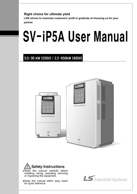
<strong>SV</strong>-<strong>iP5A</strong> <strong>User</strong> <strong>Manual</strong><br />
5.5-30 kW [200V] / 2.2-450kW [400V]<br />
� Read this manual carefully before<br />
installing, wiring, operating, servicing<br />
or inspecting this equipment.<br />
� Keep this manual within easy reach<br />
for quick reference.
Thank you for purchasing LS Variable Frequency Drives!<br />
SAFETY INSTRUCTIONS<br />
To prevent injury and property damage, follow these instructions<br />
during the installation and operation of the inverter.<br />
Incorrect operation due to ignoring these instructions may cause<br />
harm or damage. The following symbols are used throughout the<br />
manual to highlight important information.<br />
DANGER<br />
WARNING<br />
CAUTION<br />
This symbol indicates death or serious<br />
injury can occur if you do not follow<br />
instructions.<br />
This symbol indicates the possibility of<br />
death or serious injury.<br />
This symbol indicates the possibility of<br />
damage to the inverter or other<br />
components.<br />
■ The meaning of each symbol in this manual and on your<br />
equipment is as follows.<br />
This is the safety alert symbol.<br />
Read and follow instructions carefully to avoid a dangerous situation.<br />
This symbol alerts the user to the presence of “dangerous voltage”<br />
inside the product that might cause bodily harm or electric shock.<br />
■ This manual should be placed in a location where it can be<br />
accessed by users.<br />
■ This manual should be given to the person who actually<br />
uses the inverter and is responsible for its maintenance.<br />
i
WARNING<br />
� Do not remove the cover while power is applied or the unit is in<br />
operation.<br />
Otherwise, electric shock could occur.<br />
� Do not operate the inverter with the front cover removed.<br />
Otherwise, electric shock can occur due to the exposed terminals and bus bars.<br />
� Do not remove the cover except for periodic inspections or wiring,<br />
even if the input power is not applied.<br />
Otherwise, electric shock can occur due to accessing capacitor banks.<br />
� Wiring and periodic inspections should be performed at least 10<br />
minutes after disconnecting the input power and after checking the DC<br />
link voltage is discharged with a meter (below 30VDC).<br />
Otherwise, electric shock could occur.<br />
� Operate the switches with dry hands.<br />
Otherwise, electric shock could occur.<br />
� Do not use the cable when its insulating tube is damaged.<br />
Otherwise, electric shock could occur.<br />
� Do not subject the cables to scratches, excessive stress, heavy loads<br />
or pinching.<br />
Otherwise, electric shock could occur.<br />
CAUTION<br />
� Install the inverter on a non-flammable surface. Do not place flammable<br />
materials nearby.<br />
Otherwise, fire could occur.<br />
� Disconnect the input power if the inverter has been damaged.<br />
Otherwise, it could result in a secondary accident and fire.<br />
� Do not touch the inverter after shutting down or disconnecting it. It will<br />
remain hot for a couple of minutes.<br />
Otherwise, bodily injuries such as skin-burn or damage could occur.<br />
� Do not apply power to a damaged inverter or to an inverter with parts<br />
missing even if the installation is complete.<br />
Otherwise, electric shock could occur.<br />
ii
� Do not allow lint, paper, wood chips, dust, metallic chips or other<br />
foreign material into the drive.<br />
Otherwise, fire or accident could occur.<br />
OPERATING PRECAUTIONS<br />
(1) Handling and installation<br />
� The <strong>iP5A</strong> series inverter can be heavy. Lift according to the weight of the product. Use a<br />
hoist or crane to move and install the <strong>iP5A</strong> series inverter if necessary. Failure to do so<br />
may result in personal injury or damage to the inverter.<br />
� Do not stack the inverter boxes higher than the number recommended.<br />
� Install the inverter according to instructions specified in this manual.<br />
� Do not open the cover during delivery.<br />
� Do not place heavy items on the inverter.<br />
� Check that the inverter mounting orientation is correct.<br />
� Do not drop the inverter, or subject it to hard impact.<br />
� Verify the ground impedance 100ohm or less for 230 V Class inverters and 10ohm or less<br />
for 460V class inverters.<br />
� Take protective measures against ESD (Electrostatic Discharge) before touching the pcb<br />
boards during inspection, installation or repair.<br />
� The inverter is designed for use under the following environmental conditions:<br />
Environment<br />
Ambient<br />
temp.<br />
Relative<br />
humidity<br />
Storage<br />
temp.<br />
Location<br />
Altitude,<br />
Vibration<br />
Atmospheric<br />
pressure<br />
- 10 ~ 40 ℃ (14℉ ~ 104℉)<br />
90% Relative Humidity or less (non-condensing)<br />
- 20 ~ 65 ℃ (-4℉ ~ 149℉)<br />
Protected from corrosive gas, combustible gas, oil mist<br />
or dust (Pollution Degree 2 Environment)<br />
Max. 1,000m (3,300ft) above sea level, Max. 5.9m/sec 2<br />
(0.6G) or less<br />
70 ~ 106 kPa (20.67 in Hg ~ 31.3 in Hg)<br />
(2) Wiring<br />
� Do not connect power factor correction capacitors, surge suppressors, or RFI filter to the<br />
output of the inverter.<br />
� The connection orientation of the motor output cables U, V, W will affect the direction of<br />
rotation of the motor. Verify correct wiring before starting inverter.<br />
� Incorrect terminal wiring could result in inverter and/or equipment damage.<br />
� Reversing the polarity (+/-) of the terminals could damage the inverter.<br />
� Only authorized personnel familiar with LS inverter should perform wiring and inspections.<br />
� Always install the inverter before wiring. Otherwise, electric shock or bodily injury can occur.<br />
(3) Trial run<br />
� Check all parameters during operation. Parameter values might require adjustment<br />
depending on the application.<br />
� Always apply voltage within the permissible range of each terminal as indicated in this<br />
manual. Otherwise, inverter damage may result.<br />
iii
(4) Operation precautions<br />
� When the Auto restart function is selected, the inverter will restart after a fault has occurred.<br />
� The Stop key on the keypad can only be used to stop the inverter when keypad control is<br />
enabled. Install a separate emergency stop switch if necessary.<br />
� If a fault reset is made with the run command and /or reference signal present, a sudden<br />
start will occur. Check that the run command and /or reference signal is turned off in<br />
advance of resetting any faults. Otherwise an accident could occur.<br />
� Do not modify the inverter.<br />
� Depending on the motor specifications and user ETH overload settings, the motor may not<br />
be protected by electronic thermal function of inverter.<br />
� The operation of the inverter is intended to be controlled by either keypad command or<br />
control input signals. Do not use a magnetic contactor or any other device that routinely<br />
disconnects the inverter and reconnects the inverter to the input supply power for the<br />
purpose of starting and stopping the motor.<br />
� A noise filter may be installed to reduce the effect of electromagnetic interference.<br />
Otherwise nearby electronic equipment may be affected.<br />
� In cases with input voltage unbalances, install an AC input reactor.<br />
� Power Factor capacitors and generators may become overheated and damaged due to<br />
harmonics created by the inverter.<br />
� Use an insulation-rectified motor or take measures to suppress the micro surge voltage<br />
when driving 460V class motor with inverter. A micro surge voltage attributable to wiring<br />
constant is generated at motor terminals, and may deteriorate insulation and damage<br />
motor.<br />
� Before operating unit and prior to user programming, reset user parameters to default<br />
settings.<br />
� The Inverter can be set to operate a motor at high-speeds. Verify the speed capability of<br />
motor and machinery prior to operating inverter.<br />
� Holding torque is not produced when using the DC-Brake function. Install separate<br />
equipment when holding torque is required.<br />
(5) Fault prevention precautions<br />
� If required, provide a safety backup such as an emergency mechanical brake to prevent<br />
any hazardous conditions if the inverter fails during operation.<br />
(6) Maintenance, inspection and parts replacement<br />
� Do not megger (hi-pot or insulation resistance) test the power or control circuit of the<br />
inverter.<br />
� Refer to Chapter 8 for periodic inspection and parts replacement details.<br />
(7) Disposal<br />
� Handle the inverter as an industrial waste when disposing of it.<br />
(8) General instructions<br />
Many of the diagrams and drawings in this instruction manual show the inverter without a cover. Prior<br />
to operating the unit, be sure to restore covers and circuit protection according to specifications.<br />
iv
Table of Contents<br />
CHAPTER 1 - BASIC INFORMATION .................................................................................................. 1-1<br />
1.1 INSPECTION .............................................................................................................................................. 1-1<br />
1.2 BASIC CONFIGURATION ........................................................................................................................... 1-2<br />
CHAPTER 2 - SPECIFICATION ............................................................................................................. 2-1<br />
2.1 200~230V CLASS (5.5~30KW / 7.5~40HP) .............................................................................................. 2-1<br />
2.2 380~480V CLASS (5.5~30KW / 7.5~40HP) .............................................................................................. 2-1<br />
2.3 380 ~ 480V CLASS (37~90KW / 50~125HP) ............................................................................................ 2-2<br />
2.4 380 ~ 480V CLASS (110~450KW / 150~600HP) ...................................................................................... 2-2<br />
2.5 DIMENSIONS.............................................................................................................................................. 2-5<br />
CHAPTER 3 - INSTALLATION .............................................................................................................. 3-1<br />
3.1 INSTALLATION PRECAUTIONS ................................................................................................................. 3-1<br />
3.2 WIRING ..................................................................................................................................................... 3-3<br />
CHAPTER 4 - OPERATION ..................................................................................................................... 4-1<br />
4.1 PROGRAMMING KEYPADS ....................................................................................................................... 4-1<br />
1.1 SET............................................................................................................................................................ 4-2<br />
4.2 OPERATING EXAMPLE ............................................................................................................................. 4-6<br />
4.3 VARIOUS FUNCTION SETTING & DESCRIPTION .................................................................................... 4-11<br />
4.4 OPERATION EXAMPLE ........................................................................................................................... 4-17<br />
CHAPTER 5 - PARAMETER LIST ......................................................................................................... 5-1<br />
5.1 PARAMETER GROUPS ............................................................................................................................... 5-1<br />
5.2 PARAMETER LIST ..................................................................................................................................... 5-2<br />
CHAPTER 6 - PARAMETER DESCRIPTION ....................................................................................... 6-1<br />
6.1 DRIVE GROUP [DRV] ............................................................................................................................... 6-1<br />
6.2 FUNCTION 1 GROUP [FU1] .................................................................................................................... 6-10<br />
6.3 FUNCTION 2 GROUP [FU2] .................................................................................................................... 6-24<br />
6.4 INPUT/OUTPUT GROUP [I/O] ................................................................................................................. 6-37<br />
6.5 APPLICATION GROUP [APP] .................................................................................................................. 6-56<br />
CHAPTER 7 - TROUBLESHOOTING & MAINTENANCE ................................................................ 7-1<br />
7.1 FAULT DISPLAY ........................................................................................................................................ 7-1<br />
FAULT REMEDY.............................................................................................................................................. 7-3<br />
7.2 TROUBLESHOOTING ................................................................................................................................. 7-5<br />
7.3 HOW TO CHECK POWER COMPONENTS ................................................................................................. 7-6<br />
7.4 MAINTENANCE ......................................................................................................................................... 7-8<br />
CHAPTER 8 - OPTIONS ........................................................................................................................... 8-1<br />
8.1 OPTION LIST ............................................................................................................................................. 8-1<br />
8.2 EXTERNAL OPTIONS ................................................................................................................................. 8-2<br />
CHAPTER 9 - RS485 COMMUNICATION ............................................................................................ 9-1<br />
9.1 INTRODUCTION ......................................................................................................................................... 9-1<br />
9.2 SPECIFICATION ......................................................................................................................................... 9-2<br />
9.3 OPERATION ............................................................................................................................................... 9-3<br />
9.4 COMMUNICATION PROTOCOL (RS485) .................................................................................................. 9-4<br />
v
9.5 PARAMETER CODE LIST ........................................................................................................................... 9-8<br />
9.6 TROUBLESHOOTING ............................................................................................................................... 9-12<br />
9.7 ASCII CODE LIST ................................................................................................................................... 9-14<br />
APPENDIX A- UL MARKING ........................................................................................................................... I<br />
APPENDIX B- PERIPHERAL DEVICES ....................................................................................................... IV<br />
APPENDIX C- RELATED PARAMETERS ................................................................................................... VI<br />
DECLARATION OF CONFORMITY ........................................................................................................... VII<br />
EMI / RFI POWER LINE FILTERS ............................................................................................................. IX<br />
vi
CHAPTER 1 - BASIC INFORMATION<br />
1.1 Inspection<br />
- Remove the inverter from its packing and inspect its exterior for shipping damage. If damage is apparent<br />
notify the shipping agent and your LSIS sales representative.<br />
- Remove the cover and inspect the inverter for any apparent damage or foreign objects. Ensure that all<br />
mounting hardware and terminal connection hardware is properly seated, securely fastened, and<br />
undamaged.<br />
- Check the nameplate on the <strong>iP5A</strong> inverter. Verify that the inverter unit is the correct horsepower and input<br />
voltage for the application.<br />
1.1.1 Inverter model number<br />
The numbering system of the inverter is as shown below.<br />
<strong>SV</strong> 055 <strong>iP5A</strong> – 2 NE<br />
Motor rating N: No Keypad<br />
055 5.5kW<br />
900 90kW<br />
O: UL Open Type<br />
E: UL Enclosed Type 1<br />
L: Built-in DC Choke<br />
Series Name Input Voltage<br />
<strong>iP5A</strong> 2 200 - 230V<br />
4 380 - 480V<br />
1.1.2 Installation<br />
To operate the inverter reliably, install the inverter in a proper place with the correct direction and with the<br />
proper clearances.<br />
1.1.3 Wiring<br />
Connect the power supply, motor and operation signals (control signals) to the terminal block. Note that<br />
incorrect connection may damage the inverter and peripheral devices.<br />
1-1
Chapter 1 – Basic Information<br />
1.2 Basic configuration<br />
The following devices are required to operate the inverter. Proper peripheral devices must be selected and<br />
correct connections made to ensure proper operation. An incorrectly applied or installed inverter can result in<br />
system malfunction or reduction in product life as well as component damage. You must read and understand<br />
this manual thoroughly before proceeding.<br />
AC Source Supply<br />
MCCB or Earth<br />
leakage circuit<br />
breaker (ELB)<br />
Inline Magnetic<br />
Contactor<br />
AC Reactor<br />
Installation and<br />
wiring<br />
DC Reactor<br />
To motor<br />
1-2<br />
Use a power source with a voltage within the<br />
permissible range of inverter input power<br />
rating.<br />
Select circuit breakers or fuses in accordance<br />
with applicable national and local codes.<br />
Install if necessary. When installed, do not<br />
use it for the purpose of starting or stopping<br />
the drive.<br />
An AC reactor can be used when the<br />
harmonics are to be reduced and power<br />
factor is to be improved. One must be used<br />
when the inverter is installed on a power<br />
source with greater than 10 times the KVA<br />
rating of the drive.<br />
To reliably operate the drive, install the<br />
inverter in the proper orientation and with<br />
proper clearances. Incorrect terminal wiring<br />
could result in the equipment damage.<br />
A DC reactor may be used together with or<br />
in place of an AC reactor if necessary to<br />
reduce harmonics or improve power factor.<br />
Do not connect power factor capacitors,<br />
surge arrestors or radio noise filters to the<br />
output side of the inverter.
CHAPTER 2 - SPECIFICATION<br />
2.1 200~230V Class (5.5~30kW / 7.5~40HP)<br />
Model Number<br />
(<strong>SV</strong>xxx<strong>iP5A</strong>-2)<br />
055 075 110 150 185 220 300<br />
Capacity [kVA] (1) 9.1 12.2 17.5 22.9 28.2 33.5 43.8<br />
motor<br />
Fan or rating<br />
pump<br />
load<br />
Output<br />
ratings<br />
(2)<br />
HP 7.5 10 15 20 25 30 40<br />
kW<br />
Current [A]<br />
(110% overload)<br />
5.5<br />
24<br />
7.5<br />
32<br />
11 15 18.5<br />
46 60 74<br />
110% 1Minute (Normal Duty)<br />
22<br />
88<br />
30<br />
115<br />
motor<br />
General<br />
rating<br />
load<br />
(2)<br />
HP 5.5 7.5 10 15 20 25 30<br />
kW 3.7 5.5 7.5 11 15 18.5 22<br />
Current [A]<br />
17 23 33 44 54 68 84<br />
(150% overload)<br />
150% 1 Minute (Heavy Duty)<br />
Frequency 0.01 ~ 120 Hz<br />
Voltage 200 ~ 230 V (3)<br />
Input Voltage 3φ 200 ~ 230 V (-15% ~ +10 %)<br />
ratings Frequency 50/60 Hz (± 5 %)<br />
Protection degree IP20 / UL Type1 IP00 / UL Open (3)<br />
Weight [kg (lbs.)] 4.9(10.8) 6(13.2) 6(13.2) 13(28.7) 13.5(29.8) 20(44.1) 20(44.1)<br />
2.2 380~480V Class (5.5~30kW / 7.5~40HP)<br />
Model Number<br />
(<strong>SV</strong>xxx<strong>iP5A</strong>-4)<br />
055 075 110 150 185 220 300<br />
Capacity [kVA] (1) 9.6 12.7 19.1 23.9 31.1 35.9 48.6<br />
motor<br />
Fan or rating<br />
pump<br />
load<br />
Output<br />
ratings<br />
(2)<br />
HP 7.5 10 15 20 25 30 40<br />
kW<br />
Current [A]<br />
(110% overload)<br />
5.5<br />
12<br />
7.5<br />
16<br />
11 15 18.5<br />
24 30 39<br />
110% 1Minute (Normal Duty)<br />
22<br />
45<br />
30<br />
61<br />
motor<br />
rating<br />
General<br />
load<br />
(2)<br />
HP<br />
kW<br />
Current [A]/Built-in<br />
DCL Type<br />
(150% overload)<br />
5.5<br />
3.7<br />
8.8<br />
7.5<br />
5.5<br />
12<br />
10 15 20<br />
7.5 11 15<br />
16 22/24 28/30<br />
150% 1 Minute (Heavy Duty)<br />
25<br />
18.5<br />
34/39<br />
30<br />
22<br />
44/45<br />
Frequency 0.01 ~ 120 Hz<br />
Voltage 380 ~ 480 V (3)<br />
Input Voltage 3φ 380 ~ 480 V (-15% ~ +10 %)<br />
ratings Frequency 50/60 Hz (± 5 %)<br />
Protection degree IP20 / UL Type1 IP00 / UL Open (3)<br />
Standard Type 4.9(10.8)<br />
Weight [kg (lbs.)]<br />
Built-in DCL Type -<br />
6(13.2)<br />
-<br />
6(13.2)<br />
-<br />
12.5(27.6) 13(28.7) 20(44.1) 20(44.1)<br />
19.5(42.9) 19.5(42.9) 26.5(58.3) 26.5(58.3)<br />
2-1
Chapter 2 - Specification<br />
2.3 380 ~ 480V Class (37~90kW / 50~125HP)<br />
Model Number<br />
(<strong>SV</strong>xxx<strong>iP5A</strong>-4)<br />
370 450 550 750 900<br />
Capacity [kVA] (1) 59.8 72.5 87.6 121.1 145.8<br />
motor<br />
Fan or rating<br />
pump<br />
load<br />
Output<br />
ratings<br />
(2)<br />
HP<br />
50 60 75 100 125<br />
kW<br />
Current [A]<br />
(110% overload)<br />
37<br />
75<br />
45 55 75<br />
91 110 152<br />
110% 1 Minute (Normal Duty)<br />
90<br />
183<br />
motor<br />
rating<br />
General<br />
load<br />
(2)<br />
HP<br />
40 50 60 75 100<br />
kW<br />
30 37 45 55 75<br />
Current [A]<br />
(150% overload)<br />
150% 1 Minute (Heavy Duty)<br />
Frequency 0.01 ~ 120 Hz<br />
Voltage 380 ~ 480 V (3)<br />
Input Voltage 3φ 380 ~ 480 V (-15% ~ +10 %)<br />
ratings Frequency 50/60 Hz (± 5 %)<br />
Protection degree IP00 / UL Open (3)<br />
Standard Type<br />
Weight [kg (lbs.)]<br />
Built-in DCL Type<br />
27(59.5)<br />
39(86)<br />
27(59.5)<br />
40(88.2)<br />
29(64)<br />
42(92.6)<br />
42(92.6)<br />
67(147.4)<br />
43(94.8)<br />
68(149.9)<br />
2.4 380 ~ 480V Class (110~450kW / 150~600HP)<br />
Model Number<br />
(<strong>SV</strong>xxx<strong>iP5A</strong>-4)<br />
1100 1320 1600 2200 2800 3150 3750 4500<br />
Capacity [kVA] (1) 178 210 259 344 436 488 582 699<br />
motor<br />
Fan or rating<br />
pump<br />
load<br />
Output<br />
ratings<br />
(2)<br />
HP 150 200 250 300 350 400 500 600<br />
kW<br />
Current [A]<br />
(110% overload)<br />
110<br />
223<br />
132<br />
264<br />
160 220 280 315<br />
325 432 547 613<br />
110% 1 Minute (Normal Duty)<br />
375<br />
731<br />
450<br />
877<br />
motor<br />
General<br />
rating<br />
load<br />
(2)<br />
HP 125 150 200 250 300 350 400 500<br />
kW 90 110 132 160 220 280 315 375<br />
Current [A]<br />
183 223 264 325 432 547 613 731<br />
(150% overload)<br />
150% 1 Minute (Heavy Duty)<br />
Frequency 0.01 ~ 120 Hz<br />
Voltage 380 ~ 480 V (3)<br />
Input Voltage 3φ 380 ~ 480 V (-15% ~ +10 %)<br />
ratings Frequency 50/60 Hz (± 5 %)<br />
Protection degree IP00 / UL Open (4)<br />
DCL (DC Choke) Built-in External Option<br />
Weight [kg (lbs.)]<br />
101<br />
(222.7)<br />
101<br />
(222.7)<br />
114<br />
(251.3)<br />
200<br />
(441.9)<br />
200<br />
(441.9)<br />
243 380 380<br />
(535.7) (837.7) (837.7)<br />
2-2
CONTROL<br />
2-3<br />
Chapter 2 - Specification<br />
Common Specifications<br />
Cooling method Forced air cooling<br />
Short Circuit Rating<br />
65kA, suitable for use on a circuit capable of delivering not more than 100,000<br />
RMS Symmetrical amperes, 240 (or 480V) volts maximum<br />
Agency Approvals UL and cUL listed, CE marked<br />
Control Method V/F, Sensorless Vector, Slip Compensation, Easy Start Selectable<br />
Frequency Setting Digital Reference: 0.01 Hz (Below 100 Hz), 0.1 Hz (Over 100 Hz)<br />
Resolution<br />
Analog Reference: 0.01 Hz / 60 Hz<br />
Frequency Accuracy<br />
Digital: 0.01 % of Max. Output Frequency<br />
Analog: 0.1 % of Max. Output Frequency<br />
V/F Ratio Linear, Squared Pattern, <strong>User</strong> V/F<br />
Overload Capacity 110 % per 1 min, 120% per 1 min (5)<br />
Torque Boost <strong>Manual</strong> Torque Boost (0 ~ 15 % settable), Auto Torque Boost<br />
Operation Method Keypad / Terminal / Communication Operation<br />
OPERATION<br />
PROTECTION<br />
Frequency Setting<br />
Input Signal<br />
Output signal<br />
Analog: 0 ~ 12V / -12V ~ 12V / 4 ~ 20mA or 0~20mA/ Pulse / Ext-PID<br />
Digital: Keypad<br />
Start Signal Forward, Reverse<br />
Multi-Step<br />
Multi Step<br />
Accel/Decel<br />
Time<br />
Emergency<br />
Stop<br />
Up to 18 Speeds can be set including Jog (Use Programmable Digital Input<br />
Terminal)<br />
0.1~ 6,000 sec, Max 4 types can be set via Multi- Function Terminal.<br />
Accel/Decel Pattern: Linear, U-Curve, S-Curve Selectable<br />
Jog Jog Operation<br />
Interrupts the Output of Inverter<br />
Fault Reset Trip Status is Reset when Protection Function is Active<br />
Operating<br />
Status<br />
Frequency Detection Level, Overload Alarm, Stalling, Over Voltage, Low<br />
Voltage, Inverter Overheating/ Running/ Stopping/ Constant running, Inverter<br />
By-Pass, Speed Searching<br />
Fault Output Contact Output (3A, 3C, 3B) – AC 250V 1A, DC 30V 1A<br />
Choose 2 from Output Frequency, Output Current, Output Voltage, DC Link<br />
Indicator<br />
Voltage (Output Voltage: 0 ~ 10V)<br />
DC Braking, Frequency Limit, Frequency Jump, 2<br />
Operation Function<br />
nd Function, Slip<br />
Compensation, Reverse Rotation Prevention, Auto Restart, Inverter By-Pass,<br />
Auto-Tuning, PID Control, Flying Start, Safety Stop, Flux Braking, Low<br />
leakage, Pre-PID, Dual-PID, MMC (6) , Easy Start, Pre-heater<br />
Over Voltage, Low Voltage, Over Current, Ground Fault, Inverter Overheat,<br />
Motor Overheat, Output Phase Open, Overload Protection, External Fault 1, 2,<br />
Inverter Trip<br />
Communication Error, Loss of Speed Command, Hardware Fault, Option Fault<br />
etc<br />
Inverter Alarm Stall Prevention, Overload Alarm, Thermal Sensor Fault
Chapter 2 - Specification<br />
DISPLAY<br />
ENVIRONMENT<br />
Keypad<br />
Operation<br />
Information<br />
Trip<br />
Information<br />
Output Frequency, Output Current, Output Voltage, Frequency Set Value,<br />
Operating Speed, DC Voltage, Integrating Wattmeter, Fan ON time, Run-time,<br />
Last Trip Time<br />
Trips Indication when the Protection Function activates. Max. 5 Faults are<br />
saved. Last Trip Time.<br />
Ambient Temperature -10℃ ~ 40℃ (14℉ ~ 104℉) (Use loads less than 80% at 50℃)<br />
Storage Temperature -20℃ ~ 65℃ (14℉ ~ 149℉)<br />
Ambient Humidity Less Than 90 % RH Max. (Non-Condensing)<br />
Altitude – Vibration Below 1,000m (3,300ft), Below 5.9m/sec 2 (0.6g)<br />
Application Site Pollution degree 2, No Corrosive Gas, Combustible Gas, Oil Mist, or Dust<br />
(1) Rated capacity (√3×V×I) is based on 220V for 200V class and 460V for 400V class.<br />
(2) Indicates the maximum applicable capacity when using a 4-Pole standard motor.<br />
(3) IP20 or UL Enclosed Type1 can be provided by the option.<br />
(4) IP20 or UL Enclosed Type1 is not provided.<br />
(5) Overload rating 120%, 1 min is based on ambient 25℃.<br />
(6) MMC (Multi Motor Control) function is applied to the drives only for 5.5 ~ 90kW (7.5 ~125HP).<br />
2-4
2.5 Dimensions<br />
1) <strong>SV</strong>055<strong>iP5A</strong> (200/400V Class)<br />
2-5<br />
Chapter 2 - Specification<br />
mm (inches)<br />
Model W1 W2 H1 H2 D1 C1 C2 C3<br />
Enclosure<br />
Type<br />
<strong>SV</strong>055<strong>iP5A</strong>-2/4<br />
150<br />
(5.91)<br />
130<br />
(5.12)<br />
284<br />
(11.18)<br />
269<br />
(10.69)<br />
156.5<br />
(6.16)<br />
24<br />
(0.98)<br />
24<br />
(0.98)<br />
24<br />
(0.98)<br />
IP20<br />
UL Type 1
Chapter 2 - Specification<br />
2) <strong>SV</strong>075~300<strong>iP5A</strong> (200/400V Class)<br />
<br />
mm (inches)<br />
Model W1 W2 W3 H1 H2 D1 C1 C2 C3<br />
Enclosure<br />
Type<br />
<strong>SV</strong>075<strong>iP5A</strong>-2/4<br />
200<br />
(7.87)<br />
180<br />
(7.09)<br />
6<br />
(0.23)<br />
284<br />
(11.18)<br />
269<br />
(10.69)<br />
182<br />
(7.16)<br />
35<br />
(1.37)<br />
24<br />
(0.98)<br />
35<br />
(1.37)<br />
IP20<br />
UL Type 1<br />
<strong>SV</strong>110<strong>iP5A</strong>-2/4<br />
200<br />
(7.87)<br />
180<br />
(7.09)<br />
6<br />
(0.23)<br />
284<br />
(11.18)<br />
269<br />
(10.69)<br />
182<br />
(7.16)<br />
35<br />
(1.37)<br />
24<br />
(0.98)<br />
35<br />
(1.37)<br />
IP20<br />
UL Type 1<br />
<strong>SV</strong>150<strong>iP5A</strong>-2/4<br />
250<br />
(9.84)<br />
230<br />
(9.06)<br />
9<br />
(0.35)<br />
385<br />
(15.16)<br />
370<br />
(14.57)<br />
201<br />
(7.91)<br />
- - -<br />
IP00<br />
UL Open<br />
<strong>SV</strong>185<strong>iP5A</strong>-2/4<br />
250<br />
(9.84)<br />
230<br />
(9.06)<br />
9<br />
(0.35)<br />
385<br />
(15.16)<br />
370<br />
(14.57)<br />
201<br />
(7.91)<br />
- - -<br />
IP00<br />
UL Open<br />
<strong>SV</strong>220<strong>iP5A</strong>-2/4<br />
304<br />
(11.97)<br />
284<br />
(11.18)<br />
9<br />
(0.35)<br />
460<br />
(18.11)<br />
445<br />
(17.52)<br />
234<br />
(9.21)<br />
- - -<br />
IP00<br />
UL Open<br />
<strong>SV</strong>300<strong>iP5A</strong>-2/4<br />
304<br />
(11.97)<br />
284<br />
(11.18)<br />
9<br />
(0.35)<br />
460<br />
(18.11)<br />
445<br />
(17.52)<br />
234<br />
(9.21)<br />
- - -<br />
IP00<br />
UL Open<br />
2-6
2-7<br />
Chapter 2 - Specification<br />
3) <strong>SV</strong>150~300<strong>iP5A</strong> (UL Type 1 or UL Open Type with Conduit Option used, 200V/400V Class)<br />
Model W1 W2 W3 H1 H2 H3 D1 D2<br />
<strong>SV</strong>150<strong>iP5A</strong>-2/4<br />
<strong>SV</strong>185<strong>iP5A</strong>-2/4<br />
<strong>SV</strong>220<strong>iP5A</strong>-2/4<br />
<strong>SV</strong>300<strong>iP5A</strong>-2/4<br />
250<br />
(9.84)<br />
250<br />
(9.84)<br />
304<br />
(11.97)<br />
304<br />
(11.97)<br />
230<br />
(9.06)<br />
230<br />
(9.06)<br />
284<br />
(11.18)<br />
284<br />
(11.18)<br />
200.8<br />
(7.9)<br />
200.8<br />
(7.9)<br />
236<br />
(9.29)<br />
236<br />
(9.29)<br />
385<br />
(15.16)<br />
385<br />
(15.16)<br />
460<br />
(18.11)<br />
460<br />
(18.11)<br />
370<br />
(14.57)<br />
370<br />
(14.57)<br />
445<br />
(17.52)<br />
445<br />
(17.52)<br />
454.2<br />
(17.88)<br />
454.2<br />
(17.88)<br />
599.2<br />
(23.59)<br />
599.2<br />
(23.59)<br />
201<br />
(7.91)<br />
201<br />
(7.91)<br />
234<br />
(9.21)<br />
234<br />
(9.21)<br />
146<br />
(5.74)<br />
146<br />
(5.74)<br />
177.5<br />
(6.98)<br />
177.5<br />
(6.98)<br />
mm (inches)<br />
Enclosure<br />
Type<br />
IP20<br />
UL Type 1<br />
IP20<br />
UL Type 1<br />
IP20<br />
UL Type 1<br />
IP20<br />
UL Type 1<br />
Note) Mounting NEMA 1 conduit option to the 15~90Kw(20~125HP) Open Type meets NEMA 1 but does not<br />
comply with UL Enclosed Type 1. To that end, please purchase UL Type 1 product.
Chapter 2 - Specification<br />
4) <strong>SV</strong>150 ~ <strong>SV</strong>300 <strong>iP5A</strong> (400V Class) – Built-in DCL Type<br />
Model W1 W2 W3 H1 H2 D1<br />
mm (inches)<br />
Enclosure<br />
Type<br />
<strong>SV</strong>150, 185<strong>iP5A</strong>-4L 250 186 7 403.5 392 261.2 IP00<br />
(Built-in DCL Type) (9.84) (7.32) (0.28) (15.88) (15.43) (10.28) UL Type 1<br />
<strong>SV</strong>220, 300<strong>iP5A</strong>-4L 260 220 7 480 468.5 268.6 IP20<br />
(Built-in DCL Type) (10.23) (8.66) (0.28) (18.89) (18.44) (10.57) UL Type 1<br />
2-8
2-9<br />
Chapter 2 - Specification<br />
5) <strong>SV</strong>150 ~ <strong>SV</strong>300 <strong>iP5A</strong> (Built-in DCL Type, UL Type 1 or UL Open Type with Conduit Option<br />
used, 400V Class)<br />
Model W1 W2 W3 H1 H2 D1 D2<br />
mm (inches)<br />
Enclosure<br />
Type<br />
<strong>SV</strong>150, 185<strong>iP5A</strong>-4L 250 186 7 475.5 392 261.2 188.4 IP20<br />
(Built-in DCL Type) (9.84) (7.32) (0.28) (18.72) (15.43) (10.28) (7.42) UL Type 1<br />
<strong>SV</strong>220, 300<strong>iP5A</strong>-4L 260 220 7 552 468.5 268.6 188.8 IP20<br />
(Built-in DCL Type) (10.23) (8.66) (0.28) (21.73) (18.44) (10.57) (7.43) UL Type 1
Chapter 2 - Specification<br />
6) <strong>SV</strong>370 ~ <strong>SV</strong>550<strong>iP5A</strong> (400V Class)<br />
Model W1 W2 W3 H1 H2 D1<br />
mm (inches)<br />
Enclosure<br />
Type<br />
<strong>SV</strong>370, 450<strong>iP5A</strong>-4<br />
300<br />
(11.81)<br />
190<br />
(7.48)<br />
9<br />
(0.35)<br />
534<br />
(21.02)<br />
515<br />
(20.28)<br />
265.6<br />
(10.46)<br />
IP00<br />
UL Open<br />
<strong>SV</strong>550<strong>iP5A</strong>-4<br />
300<br />
(11.81)<br />
190<br />
(7.48)<br />
9<br />
(0.35)<br />
534<br />
(21.02)<br />
515<br />
(20.28)<br />
292.6<br />
(11.52)<br />
IP00<br />
UL Open<br />
<strong>SV</strong>370, 450<strong>iP5A</strong>-4L 300 190 9 684 665 265.6 IP00<br />
(Built-in DCL Type) (11.81) (7.48) (0.35) (26.92) (26.18) (10.46) UL Open<br />
<strong>SV</strong>550<strong>iP5A</strong>-4L 300 190 9 684 665 292.6 IP00<br />
(Built-in DCL Type) (11.81) (7.48) (0.35) (26.92) (26.18) (11.52) UL Open<br />
2-10
7) <strong>SV</strong>370~550<strong>iP5A</strong> (UL Type 1 or UL Open Type with Conduit Option Used, 400V Class)<br />
2-11<br />
Chapter 2 - Specification<br />
mm (inches)<br />
Model W1 W2 W3 H1 H2 D1 D2<br />
Enclosure<br />
Type<br />
<strong>SV</strong>370, 450<strong>iP5A</strong>-4<br />
300<br />
(11.81)<br />
190<br />
(7.48)<br />
9<br />
(0.35)<br />
642<br />
(25.28)<br />
515<br />
(20.28)<br />
265.6<br />
(10.46)<br />
163.4<br />
(6.43)<br />
IP20<br />
UL Type 1<br />
<strong>SV</strong>550<strong>iP5A</strong>-4<br />
300<br />
(11.81)<br />
190<br />
(7.48)<br />
9<br />
(0.35)<br />
642<br />
(25.28)<br />
515<br />
(20.28)<br />
292.6<br />
(11.52)<br />
190.4<br />
(7.5)<br />
IP20<br />
UL Type 1<br />
<strong>SV</strong>370, 450<strong>iP5A</strong>-4L 300 190 9 792 665 265.6 163.4 IP20<br />
(Built-in DCL Type) (11.81) (7.48) (0.35) (31.18) (26.18) (10.46) (6.43) UL Type 1<br />
<strong>SV</strong>550<strong>iP5A</strong>-4L 300 190 9 792 665 292.6 190.4 IP20<br />
(Built-in DCL Type) (11.81) (7.48) (0.35) (31.18) (26.18) (11.52) (7.5) UL Type 1<br />
Note) Mounting NEMA 1 conduit option to the 15~90Kw(20~125HP) Open Type meets NEMA 1 but does not<br />
comply with UL Enclosed Type 1. To that end, please purchase UL Type 1 product.
Chapter 2 - Specification<br />
8) <strong>SV</strong>750, 900<strong>iP5A</strong> (400V Class)<br />
Model W1 W2 W3 H1 H2 D1<br />
<strong>SV</strong>750, 900<strong>iP5A</strong>-4<br />
<strong>SV</strong>750, 900<strong>iP5A</strong>-4L<br />
(Built-in DCL Type)<br />
370<br />
(14.57)<br />
370<br />
(14.57)<br />
220<br />
(8.66)<br />
220<br />
(8.66)<br />
9<br />
(0.35)<br />
9<br />
(0.35)<br />
2-12<br />
610<br />
(24.02)<br />
760<br />
(29.92)<br />
586.5<br />
(23.09)<br />
736.6<br />
(28.99)<br />
337.6<br />
(13.29)<br />
337.6<br />
(13.29)<br />
mm (inches)<br />
Enclosure<br />
Type<br />
IP00<br />
UL Open<br />
IP00<br />
UL Open
9) <strong>SV</strong>750, 900<strong>iP5A</strong> (UL Type 1 or UL Open Type with Conduit Option used, 400V Class)<br />
2-13<br />
Chapter 2 - Specification<br />
Model W1 W2 W3 H1 H2 D1 D2<br />
mm (inches)<br />
Enclosure<br />
Type<br />
<strong>SV</strong>750,900<strong>iP5A</strong>-4<br />
370<br />
(14.57)<br />
220<br />
(8.66)<br />
9<br />
(0.35)<br />
767.5<br />
(30.22)<br />
586.5<br />
(23.09)<br />
337.6<br />
(13.29)<br />
223.4<br />
(8.8)<br />
IP20<br />
UL Type 1<br />
<strong>SV</strong>750, 900<strong>iP5A</strong>-4L 370 220 9 917.5 736.5 337.6 223.4 IP20<br />
(Built-in DCL Type) (14.57) (8.66) (0.35) (36.12) (28.99) (13.29) (8.8) UL Type 1<br />
Note) Mounting NEMA 1 conduit option to the 15~90Kw(20~125HP) Open Type meets NEMA 1 but does not<br />
comply with UL Enclosed Type 1. To that end, please purchase UL Type 1 product.
Chapter 2 - Specification<br />
10) <strong>SV</strong>1100, 1600<strong>iP5A</strong> (400V Class)<br />
Model W1 W2 W3 H1 H2 D1<br />
<strong>SV</strong>1100,1320<strong>iP5A</strong>-4L<br />
<strong>SV</strong>1600<strong>iP5A</strong>-4L<br />
510<br />
(20.08)<br />
510<br />
(20.08)<br />
381<br />
(15.00)<br />
381<br />
(15.00)<br />
11<br />
(0.43)<br />
11<br />
(0.43)<br />
2-14<br />
768.5<br />
(30.26)<br />
844<br />
(33.23)<br />
744<br />
(29.29)<br />
819.5<br />
(32.26)<br />
422.6<br />
(16.64)<br />
422.6<br />
(16.64)<br />
mm(inches)<br />
Enclosure<br />
Type<br />
IP00<br />
UL Open<br />
IP00<br />
UL Open
11) <strong>SV</strong>2200, 2800<strong>iP5A</strong> (400V Class)<br />
Model W1 W2 W3 H1 H2 D1<br />
<strong>SV</strong>2200, 2800<strong>iP5A</strong>-4L<br />
690<br />
(27.17)<br />
581<br />
(22.87)<br />
14<br />
(0.55)<br />
2-15<br />
1063<br />
(41.85)<br />
1028<br />
(40.49)<br />
Chapter 2 - Specification<br />
449.6<br />
(17.70)<br />
mm(inches)<br />
Enclosure<br />
Type<br />
IP00<br />
UL Open
Chapter 2 - Specification<br />
12) <strong>SV</strong>3150, 4500<strong>iP5A</strong> (400V Class)<br />
Model W1 W2 W3 W4 H1 H2 D1<br />
mm(inches)<br />
Enclosure<br />
Type<br />
<strong>SV</strong>3150<strong>iP5A</strong>-4<br />
772<br />
(30.39)<br />
500<br />
(19.69)<br />
13<br />
(0.51)<br />
500<br />
(19.69)<br />
1140.5<br />
(44.90)<br />
1110<br />
(43.70)<br />
442<br />
(17.40)<br />
IP00<br />
UL Open<br />
<strong>SV</strong>3750,4500<strong>iP5A</strong>-4<br />
922<br />
(36.30)<br />
580<br />
(22.83)<br />
14<br />
(0.55)<br />
580<br />
(22.83)<br />
1302.5<br />
(51.28)<br />
1271.5<br />
(50.06)<br />
495<br />
(19.49)<br />
IP00<br />
UL Open<br />
2-16
CHAPTER 3 - INSTALLATION<br />
3.1 Installation precautions<br />
1) Handle the inverter with care to prevent damage to the plastic components. Do not hold the inverter by the<br />
front cover.<br />
2) Do not mount the inverter in a location where excessive vibration (5.9 m/sec 2 or less) is present such as<br />
installing the inverter on a press or other moving equipment.<br />
3) Install in a location where temperature is within the permissible range (-10~40°C).<br />
4) The inverter will be very hot during operation. Install it on a non-combustible surface.<br />
5) Mount the inverter on a flat, vertical and level surface. Inverter orientation must be vertical (top up) for<br />
proper heat dissipation. Also leave sufficient clearances around the inverter. However, A= Over 500mm and B=<br />
200mm should be obtained for inverters rated 30kW and above.<br />
B:5cm<br />
Min<br />
Inverter<br />
5 cm<br />
A: 10cm Min<br />
Temp<br />
checking point<br />
B:5cm<br />
Min<br />
A: 10cm Min<br />
Inverter<br />
5 cm<br />
Leave space enough to allow<br />
cooled air flowing easily<br />
between wiring duct and the<br />
unit.<br />
3-1<br />
Temp checking<br />
point<br />
5 cm<br />
Cooling air<br />
Cooling fan
Chapter 3 - Installation<br />
6) Do not mount the inverter in direct sunlight or near other heat sources.<br />
7) The inverter shall be mounted in a Pollution Degree 2 environment. If the inverter is going to be installed in<br />
an environment with a high probability of dust, metallic particles, mists, corrosive gases, or other contaminates,<br />
the inerter must be located inside the appropriate electrical enclosure of the proper NEMA or IP rating.<br />
8) When two or more inverters are installed or a ventilation fan is mounted in inverter panel, the inverters and<br />
ventilation fan must be installed in proper positions with extreme care taken to keep the ambient temperature of<br />
the inverters below the permissible value. If they are installed in improper positions, the ambient temperature of<br />
the inverters will rise.<br />
.<br />
Inverter<br />
Panel Panel<br />
Inverter<br />
Cooling fan<br />
Inverter<br />
Inverter<br />
GOOD (O) BAD (X)<br />
[When installing several inverters in a panel]<br />
9) Install the inverter using screws or bolts to insure the inverter is firmly fastened.<br />
CAUTION<br />
■ Risk of Electric Shock<br />
More than one disconnect switch may be required<br />
to de-energize the equipment before servicing.<br />
3-2<br />
Ventilating fan<br />
GOOD (O) BAD (X)<br />
[When installing a ventilating fan in a panel]
3.2 Wiring<br />
3.2.1 Basic wiring<br />
1) For 5.5~30kW (7.5~40HP)<br />
Main Power Circuit<br />
3 φ<br />
AC Input<br />
50/60 Hz<br />
Control Circuit<br />
MCCB(Option)<br />
Programmable Digital Input 1(Speed L)<br />
Programmable Digital Input 2(Speed M)<br />
Programmable Digital Input 3(Speed H)<br />
Fault Reset (RST)<br />
Inverter Disable (BX)<br />
Jog Frequency Reference (JOG)<br />
Forward Run command (FX)<br />
Reverse Run command (RX)<br />
Common Terminal<br />
R(L1)<br />
S(L2)<br />
T(L3)<br />
G<br />
M1<br />
M2<br />
M3<br />
M4<br />
M6<br />
M7<br />
M8<br />
CM<br />
P1(+)<br />
P2(+)<br />
3-3<br />
Dynamic<br />
Braking Unit<br />
(Optional)<br />
N(-)<br />
U<br />
V<br />
W<br />
DB Unit(Optional)<br />
DB Resistor<br />
DC Bus Choke (Optional )<br />
P N B1 B2<br />
DC Bus Choke DB Resistor<br />
Programmable Digital Output<br />
RS485 Signal<br />
RS485 Common<br />
M5<br />
A1<br />
C1<br />
A2<br />
C2<br />
A3<br />
C3<br />
A4<br />
C4<br />
C-<br />
C+<br />
CM<br />
Note : 1) 5G is Common Ground for Analog Input/Output.<br />
2) Use terminal V1 for V1, V1S (0~12V, -12 ~ 12V) input.<br />
+ -<br />
+ -<br />
V+<br />
V1<br />
5G<br />
I<br />
V-<br />
S0<br />
S1<br />
5G<br />
3A<br />
3C<br />
3B<br />
A0<br />
B0<br />
5G<br />
NT<br />
5G<br />
Chapter 3 - Installation<br />
MOTOR<br />
Analog Power Source (+12V)<br />
Frequency reference (0~12V,V1S : -12~12V)<br />
Frequency reference common terminal<br />
Frequency reference (0~20mA or 4~20mA)<br />
Analog Power Source (-12V)<br />
Output Frequency Meter<br />
Output Voltage Meter<br />
Common for output meter signal<br />
Fault Contact Ouput<br />
less than AC250V (DC30V), 1A<br />
Frequency Reference (Pulse : 0 ~ 100kHz)<br />
Common for Frequency Reference (Pulse)<br />
External motor thermal detection
Chapter 3 - Installation<br />
2) For 37~90kW (50~125HP) / 315~450(400~600HP)<br />
Main Power Circuit<br />
3 φ<br />
AC Input<br />
50/60 Hz<br />
Control Circuit<br />
Programmable Digital Input 1(Speed L)<br />
MCCB(Option)<br />
Programmable Digital Input 2(Speed M)<br />
Programmable Digital Input 3(Speed H)<br />
Fault Reset (RST)<br />
Inverter Disable (BX)<br />
Jog Frequency Reference (JOG)<br />
Forward Run command (FX)<br />
Reverse Run command (RX)<br />
Common Terminal<br />
Programmable Digital Output<br />
R(L1)<br />
S(L2)<br />
T(L3)<br />
G<br />
M1<br />
M2<br />
M3<br />
M4<br />
M6<br />
M7<br />
M8<br />
CM<br />
P1(+)<br />
P2(+)<br />
3-4<br />
Dynamic<br />
Braking Unit<br />
(Optional)<br />
N(-)<br />
U<br />
V<br />
W<br />
DB Unit(Optional)<br />
DB Resistor<br />
DC Bus Choke (Optional )<br />
P N B1 B2<br />
DC Bus Choke DB Resistor<br />
RS485 Signal<br />
RS485 Common<br />
M5<br />
A1<br />
C1<br />
A2<br />
C2<br />
A3<br />
C3<br />
A4<br />
C4<br />
C-<br />
C+<br />
CM<br />
+ -<br />
+ -<br />
V+<br />
V1<br />
CM<br />
I<br />
V-<br />
S0<br />
S1<br />
5G<br />
3A<br />
3C<br />
3B<br />
A0<br />
B0<br />
CM<br />
ET<br />
5G<br />
MOTOR<br />
Analog Power Source (+12V)<br />
Frequency reference (0~12V,V1S : -12~12V)<br />
Frequency reference common terminal<br />
Frequency reference (0~20mA or 4~20mA)<br />
Analog Power Source (-12V)<br />
Output Frequency Meter<br />
Output Voltage Meter<br />
Common for output meter signal<br />
Fault Contact Output<br />
less than AC250V (DC30V), 1A<br />
Frequency Reference (Pulse : 0 ~ 100kHz)<br />
Common for Frequency Reference<br />
External motor thermal detection<br />
Note : 1) 5G is Common Ground for Analog Meter Output(SO,S1) and External motor thermal detection(ET).<br />
2) Use terminal V1 for V1, V1S (0~12V, -12 ~ 12V) input.
3) For 110~280kW (150~350HP)<br />
Main Power Circuit<br />
3 φ<br />
AC Input<br />
50/60 Hz<br />
Control Circuit<br />
Programmable Digital Input 1(Speed L)<br />
Programmable Digital Input 2(Speed M)<br />
Programmable Digital Input 3(Speed H)<br />
Fault Reset (RST)<br />
Inverter Disable (BX)<br />
Jog Frequency Reference (JOG)<br />
Forward Run command (FX)<br />
Reverse Run command (RX)<br />
Common Terminal<br />
Programmable Digital Output<br />
RS485 Signal<br />
RS485 Common<br />
R(L1)<br />
S(L2)<br />
T(L3)<br />
G<br />
M1<br />
M2<br />
M3<br />
M4<br />
M5<br />
M6<br />
M7<br />
M8<br />
CM<br />
A1<br />
C1<br />
A2<br />
C2<br />
A3<br />
C3<br />
A4<br />
C4<br />
C-<br />
C+<br />
CM<br />
P2(+)<br />
3-5<br />
Dynamic<br />
Braking Unit<br />
(Optional)<br />
P N B1 B2<br />
DC Reactor(Built-in)<br />
+ -<br />
+ -<br />
U<br />
V<br />
W<br />
V+<br />
V1<br />
CM<br />
I<br />
V-<br />
S0<br />
S1<br />
5G<br />
3A<br />
3C<br />
3B<br />
A0<br />
B0<br />
CM<br />
ET<br />
5G<br />
DB Unit(Optional)<br />
DB Resistor<br />
DB Resistor<br />
Chapter 3 - Installation<br />
MOTOR<br />
Analog Power Source (+12V)<br />
Frequency reference (0~12V,V1S : -12~12V)<br />
Frequency reference common terminal<br />
Frequency reference (0~20mA or 4~20mA)<br />
Analog Power Source (-12V)<br />
Output Frequency Meter<br />
Output Voltage Meter<br />
Common for output meter signal<br />
Fault Contact Output<br />
less than AC250V (DC30V), 1A<br />
Frequency Reference (Pulse : 0 ~ 100kHz)<br />
Common for Frequency Reference<br />
External motor thermal detection<br />
Note : 1) 5G is Common Ground for Analog Meter Output(SO,S1) and External motor thermal detection(ET).<br />
2) Use terminal V1 for V1, V1S (0~12V, -12 ~ 12V) input.<br />
3) DC Reactor is built basically in the inverters for 110~280kW(150~350HP).
Chapter 3 - Installation<br />
4) For 15~30kW (20~40HP) Built-in DCL Type<br />
3 φ<br />
AC Input<br />
50/60 Hz<br />
R(L1)<br />
S(L2)<br />
T(L3)<br />
G<br />
DC Reactor<br />
5) For 37~90kW (50~125HP) Built-in DCL Type<br />
3 φ<br />
AC Input<br />
50/60 Hz<br />
R(L1)<br />
S(L2)<br />
T(L3)<br />
G<br />
P1(+)<br />
DC Reactor<br />
3-6<br />
P(+)<br />
P2(+)<br />
P N B1 B2<br />
N(-)<br />
U<br />
V<br />
W<br />
P N B1 B2<br />
N(-)<br />
U<br />
V<br />
W<br />
DB Resistor<br />
Motor<br />
DB Resistor<br />
Motor<br />
☞ Note : P1(+) is not provided for wiring.
6) Power Terminals:<br />
(1) 5.5 ~ 30 kW (200V/400V Class)<br />
3-7<br />
Chapter 3 - Installation<br />
R(L1) S(L2) T(L3) G P1(+) P2(+) N(-) U V W<br />
(2) 37~90kW (50~125HP) / 315~450kW (400~600HP) <br />
R(L1) S(L2) T(L3) P1(+) P2(+) N(-) U V W<br />
Jumper<br />
Jumper<br />
(3) 15~18.5kW (20~25HP) <br />
G R(L1) S(L2) T(L3) P(+) N(-) U V W G<br />
(4) 22~30kW (30~40HP) <br />
R(L1) S(L2) T(L3) P(+) N(-) U V W<br />
(5) 37~90kW (50~125HP) / 110 ~280kW (150~350HP) <br />
R(L1) S(L2) T(L3) P2(+) N(-) U V W<br />
☞ Note : P1(+) is not provided for wiring.<br />
Symbol Description<br />
R(L1), S(L2), T(L3) AC Line Voltage Input<br />
G Earth Ground<br />
P1(+), P2(+) External DC Reactor (P1(+)-P2(+)) Connection Terminals<br />
(Jumper must be removed).<br />
P2(+) ,N(-) or DB Unit (P2(+)-N(-)) Connection Terminals<br />
P(+), N(-)<br />
U, V, W 3 Phase Power Output Terminals to Motor
Chapter 3 - Installation<br />
7) Control circuit terminal<br />
5.5 ~ 30kW/7.5~40HP (200V/400V Class)<br />
3A 3C 3B A1 C1 A2 C2 A3 C3 A4 C4<br />
37 ~ 450 kW/ 50~600HP (400V Class)<br />
3A 3C 3B A1 C1 A2 C2 A3 C3 A4 C4<br />
3-8<br />
C+ CM C- M6 24 M7 M8<br />
M1 CM M2 M3 24 M4 M5<br />
C+ CM C- M6 24 M7 M8<br />
M1 CM M2 M3 24 M4 M5<br />
A0 B0 5G 5G S0 S1<br />
V+ V1 5G V- I NT<br />
CM NC 5G 5G ET S0 S1<br />
V+ V1 CM V- I A0 B0
Input signal<br />
Output signal<br />
Starting Contact Function Select<br />
Analog frequency setting<br />
External<br />
motor<br />
thermal<br />
detection<br />
3-9<br />
Chapter 3 - Installation<br />
Type Symbol Name Description<br />
M1, M2, M3<br />
Programmable<br />
Digital Input 1, 2, 3<br />
Defines Programmable Digital Inputs.<br />
(Factory setting: Multi-Step Frequency 1, 2, 3)<br />
FX [M7]<br />
Forward Run<br />
Command<br />
Forward Run When Closed and Stopped When Open.<br />
RX [M8]<br />
Reverse Run<br />
Command<br />
Reverse Run When Closed and Stopped When Open.<br />
JOG [M6]<br />
Jog Frequency<br />
Reference<br />
Runs at Jog Frequency when the Jog Signal is ON. The<br />
Direction is set by the FX (or RX) Signal.<br />
When the BX Signal is ON the Output of the Inverter is<br />
Turned Off. When Motor uses an Electrical Brake to Stop,<br />
BX [M5] Inverter Disable<br />
BX is used to Turn Off the Output Signal. Take caution<br />
when BX Signal is OFF (Not Turned Off by Latching)<br />
and FX Signal (or RX Signal) is ON. If so, motor<br />
continues to Run.<br />
RST [M4] Fault Reset Used for Fault Reset.<br />
CM<br />
Sequence Common<br />
(NPN) / 24V Com.<br />
Common terminal for NPN contact input and also<br />
common for the external 24V supply.<br />
Sequence Common Common 24V terminal for PNP contact input.<br />
24<br />
(PNP) / Ext. Can also be used as a 24Vdc external power supply<br />
+24Vdc supply (maximum output : +24V, 50mA)<br />
V+, V-<br />
Analog Power<br />
Source (+12V,-12V)<br />
Power supply for Analog Frequency Setting.<br />
Maximum Output: +12V, 100mA, -12V, 100mA.<br />
V1<br />
Frequency Reference<br />
(Voltage)<br />
Used by a DC 0-12V or –12~ 12 V input to set the<br />
frequency reference. (Input impedance is 20 kΩ)<br />
I<br />
Frequency Reference<br />
(Current)<br />
Used by a 0-20mA input to set the frequency reference.<br />
(Input impedance is 249Ω)<br />
A0, B0<br />
Frequency Reference<br />
(Pulse)<br />
Used by a pulse input to set the frequency reference.<br />
5G (~30kW) Frequency Reference Common Terminal for Analog Frequency Reference<br />
CM(37kW~) Common Terminal Signal.<br />
NT (~30kW) External motor Motor thermal sensor input. Used to prevent motor from<br />
ET (37kw ~) thermal detection overheating by using a NTC or PTC thermal sensor.<br />
5G<br />
Common for NT(or<br />
ET)<br />
Common Terminal for External motor thermal detection.<br />
RS485<br />
terminal<br />
C+, C-<br />
CM<br />
RS485 signal High,<br />
Low<br />
RS485 common<br />
RS485 signal (See RS485 communication in the manual<br />
for more details.)<br />
Common Ground. Terminal for RS485 interface.<br />
Voltage output for one of the following: Output<br />
Voltage S0, S1,5G<br />
Programmable<br />
Voltage Output<br />
Frequency, Output Current, Output Voltage, DC Link<br />
Voltage. Default is set to Output Frequency. (Maximum<br />
Output Voltage and Output Current are 0-12V and 1mA).<br />
Energizes when a fault is present. (AC250V, 1A; DC30V,<br />
Contact<br />
3A, 3C, 3B Fault Contact Output<br />
1A)<br />
Fault: 3A-3C Closed (3B-3C Open)<br />
Normal: 3B-3C Closed (3A-3C Open)<br />
A1~4, Programmable Defined by Programmable Digital Output terminal<br />
C1~4 Digital Output settings (AC250V, 1A; DC30V, 1A)<br />
Note) M1~M8 terminals are <strong>User</strong> Programmable.
Chapter 3 - Installation<br />
3.2.2 Wiring power terminals<br />
◈ Wiring Precautions<br />
1) The internal circuits of the inverter will be damaged if the incoming power is connected and applied to<br />
output terminals (U, V, W).<br />
2) Use ring terminals with insulated caps when wiring the input power and motor wiring.<br />
3) Do not leave wire fragments inside the inverter. Wire fragments can cause faults, breakdowns, and<br />
malfunctions.<br />
4) For input and output, use wires with sufficient size to ensure voltage drop of less than 2%.<br />
5) Motor torque may drop of operating at low frequencies and a long wire run between inverter and motor.<br />
6) The cable length between inverter and motor should be less than 150m (492ft). Due to increased leakage<br />
capacitance between cables, overcurrent protective feature may operate or equipment connected to the<br />
output side may malfunction. (But for products of less than 30kW, the cable length should be less than 50m<br />
(164ft).)<br />
7) The main circuit of the inverter contains high frequency noise, and can hinder communication<br />
equipment near the inverter. To reduce noise, install line noise filters on the input side of the inverter.<br />
8) Do not use power factor capacitor, surge killers, or RFI filters on the output side of the inverter. Doing<br />
so may damage these components.<br />
9) Always check whether the LCD and the charge lamp for the power terminal are OFF before wiring<br />
terminals. The charge capacitor may hold high-voltage even after the power is disconnected. Use caution to<br />
prevent the possibility of personal injury.<br />
10) Do not connect with MC at output pare of inverter and make MC On/Off during operation. It can cause<br />
the Trip or damage of inverter<br />
◈ Grounding<br />
1) The inverter is a high switching device, and leakage current may flow. Ground the inverter to avoid<br />
electrical shock. Use caution to prevent the possibility of personal injury. The ground impedance for 200V<br />
class is 100 ohm with 400V class 10ohm.<br />
2) Connect only to the dedicated ground terminal of the inverter. Do not use the case or the chassis screw<br />
for grounding.<br />
3) The protective earth conductor must be the first one in being connected and the last one in being<br />
disconnected.<br />
4) As a minimum, grounding wire should meet the specifications listed below. Grounding wire should be<br />
as short as possible and should be connected to the ground point as near as possible to the inverter.<br />
Inverter Capacity Grounding wire Sizes, AWG or kcmil (mm²)<br />
kW HP 200V Class 400V Class<br />
5.5 ~ 7.5 7.5 ~ 10 10 (5.5) 12 (3.5)<br />
11 ~ 15 15 ~ 20 6 (14) 8 (8)<br />
18.5 ~ 30 25 ~ 40 4 (22) 6 (14)<br />
37 ~ 55 50 ~ 75 - 4 (22)<br />
75 ~ 90 100 ~ 125 - 2 (38)<br />
110 ~132 150 ~ 200 - 1/0 (60)<br />
160 ~ 280 250 ~ 350 - 4/0 (100)<br />
315 ~ 375 400 ~ 600 - 300 (150)<br />
450 700 - 400 (200)<br />
3-10
3.2.3 Wires and terminal lugs<br />
3-11<br />
Chapter 3 - Installation<br />
Refer to below for wires, terminal lugs, and screws used to connect the inverter power input and output.<br />
Inverter capacity<br />
Terminal<br />
screw<br />
Screw torque<br />
Wire size<br />
R(L1), S(L2), T(L3) U, V, W<br />
size<br />
kgf · cm lb · in mm 2 AWG or<br />
kcmil<br />
mm 2 AWG or<br />
kcmil<br />
5.5kW(7.5HP) M4 7.1 ~ 12.2 6.2~10.6 5.5 10 5.5 10<br />
2<br />
0<br />
0<br />
V<br />
7.5kW(10HP)<br />
11kW(15HP)<br />
15kW(20HP)<br />
18.5kW(25HP)<br />
22kW(30HP)<br />
30kW(40HP)<br />
M5<br />
M5<br />
M6<br />
M6<br />
M8<br />
M8<br />
24.5 ~ 31.8<br />
30.6 ~ 38.2<br />
61.2 ~ 91.8<br />
21.2~27.6<br />
26.6~33.2<br />
53.1~79.7<br />
8<br />
14<br />
22<br />
38<br />
38<br />
60<br />
8<br />
6<br />
4<br />
2<br />
2<br />
1/0<br />
8<br />
14<br />
22<br />
38<br />
38<br />
60<br />
8<br />
6<br />
4<br />
2<br />
2<br />
1/0<br />
5.5kW(7.5HP) M4<br />
3.5 12 3.5 12<br />
7.5Kw(10HP) M4 7.1 ~ 12.2 6.2~10.6 3.5 12 3.5 12<br />
11 kW(15HP) M4 5.5 10 5.5 10<br />
15 kW(20HP)<br />
18.5kW(25HP)<br />
M6<br />
M6<br />
30.6~38.2 26.6~33.2<br />
8<br />
14<br />
8<br />
6<br />
8<br />
14<br />
8<br />
6<br />
22~30kW<br />
(30~40HP)<br />
M8 61.2~91.8 53.1~79.7 22 4 22 4<br />
4<br />
0<br />
0<br />
V<br />
37~55kW<br />
(50~75HP)<br />
75~90kW<br />
(100~125HP)<br />
110~132Kw<br />
(150~200HP)<br />
160kW(250HP)<br />
M8<br />
M10<br />
M12<br />
M12<br />
67.3~87.5<br />
89.7~122.0<br />
182.4~215.0<br />
58.4~75.9<br />
77.9~105.9<br />
158.3~186.6<br />
38<br />
60<br />
100<br />
150<br />
2<br />
1/0<br />
4/0<br />
300<br />
38<br />
60<br />
100<br />
150<br />
2<br />
1/0<br />
4/0<br />
300<br />
220kW(300HP) M12 200 400 200 400<br />
280kW(350HP) M12<br />
250 500 250 500<br />
315kW(400HP)<br />
375kW(500HP)<br />
M12<br />
M12<br />
182.4~215.0 158.3~186.6<br />
325<br />
2×200<br />
700<br />
2×400<br />
325<br />
2×200<br />
700<br />
2×400<br />
450kW(600HP) M12 2×250 2×500 2×250 2×500<br />
* Apply the rated torque to terminal screws.<br />
* Loose screws can cause of short circuit or malfunction. Tightening the screw too much can damage the terminals and<br />
cause a short circuit or malfunction.<br />
* Use copper wires only with 600V, 75℃ ratings. For 7.5~11kW 240V type inverters, R(L1), S(L2), T(L3) and U, V, W<br />
terminals are only for use with insulated ring type connector.
Chapter 3 - Installation<br />
Power and Motor Connection Example (5.5~30kW inverters)<br />
R(L1) S(L2) T(L3) G P1(+) P2(+) N(-) U V W<br />
Power supply must be<br />
connected to the R(L1), S(L2),<br />
and T(L3) terminals.<br />
Connecting it to the U, V, and<br />
W terminals causes internal<br />
damages to the inverter.<br />
Arranging the phase sequence is<br />
not necessary.<br />
3.2.4 Control circuit wiring<br />
1) Wiring Precautions<br />
CM and 5G terminals are insulated each other. Do not connect these terminals together or to the power<br />
ground.<br />
Use shielded wires or twisted wires for control circuit wiring, and separate these wires from the main power<br />
circuits and other high voltage circuits (200V relay sequence circuit).<br />
It is recommended to use the cables of 0.0804mm 2 (28 AWG) ~ 1.25mm 2 (16 AWG) for TER1, TER2<br />
control terminals and the cables of 0.33mm 2 (22 AWG) ~ 2.0mm 2 (14 AWG) for TER3, TER4 control<br />
terminals.<br />
2) Control terminal layout<br />
3A 3C 3B A1 C1 A2 C2 A3 C3 A4 C4<br />
Ground<br />
C+ CM C- M6 24 M7 M8<br />
M1 CM M2 M3 24 M4 M5<br />
3-12<br />
Ground<br />
TER4 TER3 TER2 TER1<br />
0.33mm 2 (22 AWG) ~ 2.0mm 2 (14 AWG) 0.08<br />
Motor should be connected to the U, V,<br />
and W terminals.<br />
If the forward command (FX) is on, the<br />
motor should rotate counter clockwise when<br />
viewed from the load side of the motor. If<br />
the motor rotates in the reverse, switch the U<br />
and V terminals.<br />
A0 B0 5G 5G S0 S1<br />
V+ V1 5G V- I NT<br />
Forward
3) Sink mode(NPN mode) / Source mode(PNP mode)<br />
3-13<br />
Chapter 3 - Installation<br />
<strong>SV</strong>-<strong>iP5A</strong> provides Sink/Source(NPN/PNP) modes for sequence input terminal on the control circuit.<br />
The logic of the input terminal is setable to Sink mode(NPN mode) / Source mode(NPN mode) by using the J1<br />
switch. Connection method is shown below.<br />
(1) Sink mode(NPN mode)<br />
- Put J1 switch down to set to Sink mode(NPN mode). CM terminal (24V GND) is common terminal for<br />
contact signal input.<br />
- The factory default is Sink mode(NPN mode).<br />
(2) Source mode(PNP mode) - Internal Power Supply used<br />
- Put J1 switch up to set to Source mode(PNP mode). Terminal 24 (24V Power Supply) is common<br />
terminal for contact input signal.<br />
(3) Source mode(PNP mode) - External Power Supply used<br />
- Put J1 switch up to set to Source mode(PNP mode).<br />
- To use external 24V Power Supply, make a sequence between external Power Supply (-) terminal and<br />
CM(24V GND) terminal.<br />
J1<br />
PNP<br />
NPN<br />
Sink mode(NPN mode)<br />
CM(24G)<br />
M7(FX)<br />
M8(RX)<br />
Internal Power<br />
Supply(24V)<br />
External Power<br />
Supply (24V)<br />
J1<br />
PNP<br />
J1<br />
Source mode(PNP mode)<br />
- External Powe Supply used<br />
NPN CM(24G)<br />
-<br />
+<br />
PNP<br />
I/O ▶ Jump code<br />
00 1<br />
NPN<br />
24(24V)<br />
M7(FX)<br />
M8(RX)<br />
M7(FX)<br />
M8(RX<br />
Internal Power<br />
Supply(24V)
Chapter 3 - Installation<br />
3.2.5 RS485 circuit wiring<br />
TER 2<br />
C+ CM C- M6 24 M7 M8<br />
M1 CM M2 M3 24 M4 M5<br />
Use C+ (RS485 signal High), C- (RS485 signal LOW) in TER 2. Turn the J3 switch ON (Upward) to connect the<br />
termination resistor (120 ohm). J3 switch is on the left side of the TER2.<br />
Item Specification<br />
Transmission type Bus method, Multi drop Link System<br />
Applicable inverter <strong>SV</strong>-<strong>iP5A</strong> series<br />
Number of inverters Max.31<br />
Transmission distance Within 1200m Max. (700m desired)<br />
Recommendable cable 0.75mm 2 (18AWG), Shield Type Twisted-pair Wire<br />
Item Specification<br />
Installation C+, C-, CM terminals on the control terminal block<br />
Power supply Insulated from the inverter power supply<br />
3.2.6 Check points on wiring<br />
1) Electrical or mechanical interlock of MC1 and MC2 is required for Inverter Bypass Operation. Otherwise,<br />
chattering may occur or input power may flow to inverter output, damaging the inverter.<br />
2) Make the sequence to disable the Auto restart after power failure if required. Otherwise, inverter will be<br />
automatically restarted.<br />
3) Do not apply the voltage directly to control circuit input terminals such as FX, RX.<br />
3-14<br />
J3<br />
ON<br />
OFF
CHAPTER 4 - OPERATION<br />
4.1 Programming Keypads<br />
4.1.1 LCD Keypad<br />
LCD keypad can display up to 32 alphanumeric characters, and various settings can be checked directly from<br />
the display. The following is an illustration of the keypad.<br />
32 character, background<br />
light, LCD display. The<br />
background tone is<br />
adjustable.<br />
The Mode Button moves<br />
you through the seven<br />
program groups:<br />
DRV �[Mode] �<br />
FUN1� [ENT]�DRV<br />
Reverse Run Button<br />
The Reverse Run LED<br />
blinks when the drive<br />
Accels or Decels.<br />
4-1<br />
The Program Button is<br />
used to go into<br />
programming mode to<br />
change data.<br />
The Enter Button is used<br />
to enter changed data<br />
within a parameter.<br />
DRV� [ENT]� APP�<br />
[MODE] � DRV<br />
[SHIFT] This button is<br />
used to move cursor<br />
across display in<br />
programming mode.<br />
[ESC] This button is used<br />
to move the program<br />
code to DRV 00 form any<br />
program code.<br />
Forward Run Button<br />
The Forward Run LED<br />
blinks when the drive<br />
Accels or Decels.<br />
Stop Button is used to<br />
stop the drive from<br />
running.<br />
Reset Button is used to<br />
reset Faults.<br />
LED blinks when there is<br />
a fault.
Chapter 4 - Operation<br />
Detail description<br />
1) LCD Keypad Display<br />
2) Run/Stop Source<br />
1) Parameter group<br />
5) Parameter Code<br />
6) Operating Status<br />
DRV▶T/K 0.0 A<br />
00 STP 0.00 Hz<br />
Displays Description<br />
1) Parameter Group Displays the parameter group. There are DRV, FU1, FU2, I/O, EXT, COM, APP<br />
groups.<br />
2) Run/Stop Source Displays the source of motor Run and Stop<br />
K: Run/Stop using FWD, REV buttons on keypad<br />
T: Run/Stop using control terminal input FX, RX<br />
R: Run/Stop using RS485<br />
O: Run/Stop via option board<br />
3) Frequency Setting Displays the source of command frequency setting<br />
Source<br />
K: Frequency setting using keypad<br />
V: Frequency setting using V1 (0 ~12V or -12~ 12V) or V1 + I terminal<br />
I: Frequency setting using I (4 ~ 20mA) terminal<br />
P: Frequency setting using Pulse input<br />
R: Frequency setting using RS485<br />
U: Up terminal input when Up/Down operation is selected<br />
D: Down terminal input when Up/Down operation is selected<br />
S: Stop status when Up/Down operation is selected<br />
O: Frequency setting via Option board<br />
X: Frequency setting via Sub board<br />
J: Jog terminal input<br />
1 ~ 15: Step frequency operation (except Jog)<br />
4) Output Current Displays the Output Current during operation.<br />
5) Parameter Code Displays the code of a group. Use the ▲(Up), ▼(Down) key to move through<br />
0~99 codes.<br />
6) Operating Status Displays the operation information.<br />
STP: Stop Status<br />
FWD: During Forward operation<br />
REV: During Reverse operation<br />
DCB: During DC Braking<br />
LOP: Loss of Reference from Option Board (DPRAM fault)<br />
LOR: Loss of Reference from Option Board (Communication network fault)<br />
LOV: Loss of Analog Frequency Reference (V1: 0~12V, -10~12V)<br />
LOI: Loss of Analog Frequency Reference (I: 4~20mA)<br />
LOS: Loss of Reference from Sub-Board<br />
7) Inverter Output Displays the Output Frequency during run.<br />
Frequency/ Command Displays the Command Frequency during stop.<br />
Frequency<br />
4-2<br />
3) Frequency Setting Source<br />
4) Output Current<br />
7) Drive Output Frequency During Run,<br />
Command Frequency During Stop
4.1.2 Parameter setting and changing<br />
1) Press [MODE] key until the desired parameter group is displayed.<br />
DRV▶ Acc. time<br />
01 10.0 sec<br />
DRV▶ Acc. time<br />
01 10.0 sec<br />
DRV▶ Acc. time<br />
01 10.0 sec<br />
DRV▶ Acc. time<br />
01 15.0 sec<br />
DRV▶ Acc. time<br />
01 15.0 sec<br />
4-3<br />
Chapter 4 – Operation<br />
2) Press [▲] or [▼] keys to move to the desired parameter code. If you know the desired parameter code,<br />
you can set the code number of each parameter group in “Jump code”, except DRV group.<br />
3) Press [PROG] key to go into the programming mode, the cursor starts blinking.<br />
4) Press [SHIFT/ESC] key to move the cursor to the desired digit.<br />
5) Press [▲] or [▼] keys to change the data.<br />
6) Press [ENT] key to enter the data. The cursor stops blinking.<br />
Note: Data cannot be changed when 1) the parameter is not adjustable during the inverter is running (see the<br />
function list), or 2) Parameter Lock function FU2-94 [Parameter Lock] is activated.<br />
EX) Changing Accel time from 10 sec to 15 sec<br />
1) LCD keypad<br />
Move to the desired code to change.<br />
Press the [PROG] key.<br />
A Cursor (■) will appear.<br />
Use the [SHIFT] key to move the cursor.<br />
Change the data using [▲], [▼] keys.<br />
Press the [ENT] key to save the value into memory.<br />
The Cursor will disappear.
Chapter 4 - Operation<br />
4.1.3 Parameter groups<br />
The <strong>iP5A</strong> series inverter has 5 parameter groups separated according to their applications as indicated in the<br />
following table.<br />
The <strong>iP5A</strong> series inverter provides two kinds of keypad. One is 32-character alphanumeric LCD keypad and the<br />
other is 7-Segment LED keypad.<br />
Parameter<br />
Group<br />
LCD Keypad Description<br />
Drive Group DRV<br />
Command Frequency, Accel/Decel Time etc.<br />
Basic function Parameters<br />
Function 1 Group FU1<br />
Max. Frequency, Amount of Torque Boost etc.<br />
Parameters related to basic functions<br />
Function 2 Group FU2<br />
Frequency Jumps, Max/Min Frequency Limit etc.<br />
Basic Application Parameters<br />
Input / Output<br />
Group<br />
I/O<br />
Programmable Digital Input/Output Terminal<br />
Setting, Auto Operation etc. Parameters needed for<br />
Sequence Operation<br />
Application<br />
Group<br />
APP<br />
PID, MMC (Multi-Motor Control), 2 nd motor<br />
operation etc. Parameters related to Application<br />
function<br />
Refer to the function descriptions for detailed description of each group.<br />
4-4
1) Parameter Navigation (LCD Keypad)<br />
4-5<br />
Chapter 4 – Operation<br />
The parameter group moves directly to DRV group by pressing [SHIFT] key in any parameter code.<br />
Drive Group FU1 Group FU2 Group I/O Group<br />
DRV▶T/K 0.0 A<br />
00 STP 60.00Hz<br />
◀<br />
▶<br />
DRV▶ Acc. time<br />
01 10.0 sec<br />
◀<br />
DRV▶ Dec. time<br />
02 20.0 sec<br />
◀<br />
▶<br />
▶<br />
DRV▶ Drive mode<br />
03 Fx/Rx-1<br />
◀<br />
DRV▶ Freq mode<br />
04 KeyPad-1<br />
◀<br />
DRV▶ Step freq-1<br />
05 10.00 Hz<br />
◀<br />
▶<br />
▶<br />
MODE<br />
MODE<br />
FU1▶ Jump code<br />
00 1<br />
FU1▶Run prohibit<br />
03 None<br />
FU1▶Acc. pattern<br />
05 Linear<br />
FU1▶Dec. pattern<br />
06 Linear<br />
FU1▶ Stop mode<br />
07 Decel<br />
FU1▶ DcSt value<br />
08 50 %<br />
FU2▶ Jump code<br />
00 30<br />
FU2▶ Last trip-1<br />
01 -------<br />
FU2▶ Last trip-2<br />
02 -------<br />
FU2▶ Last trip-3<br />
03 -------<br />
FU2▶ Last trip-4<br />
04 -------<br />
FU2▶ Last trip-5<br />
05 -------<br />
▪ ▪ ▪ ▪<br />
▪ ▪ ▪ ▪<br />
▪ ▪ ▪ ▪<br />
▪ ▪ ▪ ▪<br />
▶<br />
DRV▶ Fault<br />
12 -------<br />
MODE<br />
MODE<br />
◀<br />
◀<br />
◀<br />
◀<br />
◀<br />
◀<br />
▶<br />
▶<br />
▶<br />
▶<br />
▶<br />
▶<br />
FU1▶ Stall Level<br />
60 150 %<br />
MODE<br />
MODE MODE<br />
FU2▶ Para. lock<br />
94 0<br />
I/O▶ Jump code<br />
00 1<br />
I/O▶ V1 filter<br />
01 10 ms<br />
I/O▶ V1 volt x1<br />
02 0.00 V<br />
I/O▶ V1 freq y1<br />
03 0.00 Hz<br />
I/O▶ V1 volt x2<br />
04 10.00 V<br />
I/O▶ V1 freq y2<br />
05 60.00 Hz<br />
I/O▶ Way1 / 2D<br />
60 Forward<br />
☞ Note: This figure shows the group and code navigation through LCD display keypad. It can be different<br />
from the actual display due to the group addition or code change.<br />
◀<br />
◀<br />
◀<br />
◀<br />
▶<br />
▶<br />
▶<br />
▶<br />
MODE<br />
MODE MODE MODE<br />
MODE<br />
MODE MODE MODE MODE<br />
MODE<br />
MODE<br />
MODE<br />
MODE<br />
MODE<br />
◀<br />
◀<br />
▶<br />
▶<br />
MODE<br />
MODE<br />
MODE<br />
◀<br />
◀<br />
◀<br />
◀<br />
◀<br />
◀<br />
▶<br />
▶<br />
▶<br />
▶<br />
▶<br />
▶<br />
MODE<br />
MODE<br />
MODE<br />
MODE
Chapter 4 - Operation<br />
4.2 Operating Example<br />
4.2.1 Easy Start Operation<br />
Easy Start Operation is activated by pressing STOP key on the Keypad for 2~3 seconds and inverter begins<br />
operation via Keypad (FWD/REV RUN/STOP). Drive mode is preset to V/F and reference frequency to<br />
JOG.<br />
4.2.2 Operation via Control terminal + Keypad<br />
Setting: DRV-03 [Drive Mode (Run/Stop method)] = Fx/Rx-1<br />
DRV-04 [Frequency Mode (Freq. setting method)] = Keypad<br />
With above setting, Freq setting via terminal & Run/Stop via Keypad disabled<br />
1) Check the LCD display when Power ON. Otherwise, change the setting correctly as shown above.<br />
DRV▶T/K 0.0 A<br />
00 STP 0.00Hz<br />
2) Turn the FX (or RX) terminal ON. Then FWD (or REV) LED will be lit.<br />
DRV▶T/K 0.0 A<br />
00 FWD 0.00Hz<br />
3) When setting the Ref. Freq to 60 Hz using PROG/ENT/SHIFT, ▲ keys, the motor will rotate at 60Hz.<br />
FWD (or REV) LED will be flickering during Acceleration/ Deceleration.<br />
DRV▶ Cmd. freq<br />
00 0.00Hz<br />
4) Turn the FX (or RX) terminal Off. Then Stop LED will be lit.<br />
DRV▶T/K 0.0 A<br />
00 STP 60.00Hz<br />
DRV▶ Cmd. freq<br />
00 60.00Hz<br />
Note) To enable Run/Stop via keypad & Freq setting via control terminal…<br />
Setting: DRV-03 [Drive Mode (Run/Stop method)] = Keypad<br />
DRV-04 [Frequency Mode (Freq. setting method)] = V1, V1S or I<br />
4-6<br />
DRV▶T/K 5.0 A<br />
00 FWD 60.00Hz
Operation<br />
Freq Setting via Keypad + Run/Stop via Terminal (FX/RX)<br />
Example (1)<br />
[Operation condition]<br />
-. Control mode: V/F control<br />
-. Ref. Frequency: 50[Hz] setting via keypad<br />
-. Accel/Decel time: Accel – 10 [sec], Decel – 20 [sec]<br />
-. Drive mode: Run/Stop via FX/RX terminal, Control terminal: NPN mode<br />
[Wiring]<br />
3P<br />
AC<br />
INPUT<br />
S/W<br />
R(L1)<br />
S(L2)<br />
T(L3)<br />
G<br />
M8(RX)<br />
M7(FX)<br />
M6<br />
M5<br />
M4<br />
M3<br />
M2<br />
M1<br />
CM<br />
Step Parameter setting Code Description<br />
4-7<br />
U<br />
V<br />
W<br />
S0<br />
S1<br />
5G<br />
3A<br />
3C<br />
3B<br />
1 Drive Mode DRV-3 Set it to 1 FX/RX-1.<br />
2 Frequency Mode DRV-4 Set it to 0 Keypad-1.<br />
3<br />
50[Hz] freq<br />
command setting<br />
4 Accel/Decel time DRV-1<br />
DRV-2<br />
5 Terminal FX (M7) I/O-26<br />
6 Terminal RX (M8) I/O-27<br />
IM<br />
DRV-0 Set freq command 50[Hz] via Keypad.<br />
Chapter 4 – Operation<br />
Set Accel time to 10 [sec] in DRV-1.<br />
Set Decel time to 20 [sec] in DRV-2.<br />
Motor starts to rotate in Forward direction at 50Hz<br />
with Accel time 10 [sec] when FX terminal is turned<br />
ON.<br />
Motor decelerates to stop with Decel time 20[sec]<br />
when FX terminal is turned OFF.<br />
When RX terminal is turned ON motor starts to rotate<br />
in Reverse direction at 50[Hz] with Accel time 10<br />
[sec]. When it is OFF, motor decelerates to stop with<br />
Decel time 20 [sec].
Chapter 4 - Operation<br />
4.2.3 Operation via Control Terminal<br />
Setting: DRV-03 [Drive Mode (Run/Stop method)] = 1 (Fx/Rx-1)<br />
DRV-04 [Frequency Mode (Freq. setting method)] = 2 (V1)<br />
1) Check the LCD display when Power ON. Otherwise, change the setting correctly as shown above.<br />
DRV▶T/V 0.0 A<br />
00 STP 0.00Hz<br />
2) Turn the FX (or RX) terminal ON. Then FWD (or REV) LED will be lit.<br />
DRV▶T/V 0.0 A<br />
00 FWD 0.00Hz<br />
3) Set the frequency using V1 (Potentiometer), Output freq (60Hz). Rotating direction (FWD or REV) and<br />
output current (5A) will be displayed on the LCD.<br />
DRV▶T/V 5.0 A<br />
00 FWD 60.00Hz<br />
4) Output freq value is decreasing when turning the potentiometer counterclockwise. Inverter output stops at<br />
0.00Hz and motor is stopped.<br />
DRV▶T/V 0.0 A<br />
00 FWD 0.00Hz<br />
5) Turn FX (or RX) terminal OFF.<br />
DRV▶T/V 0.0 A<br />
00 STP 0.00Hz<br />
4-8
Operation<br />
Analog Voltage Input (V1) + Operation via Terminal (FX/RX)<br />
Example (2)<br />
[Operation condition]<br />
-. Control mode: V/F control<br />
-. Reference Frequency: 50[Hz] analog input via V1 (Potentiometer)<br />
-. Accel/Decel time: Accel – 10 [sec], Decel – 20 [sec]<br />
-. Drive mode: Run/Stop via FX/RX terminal, Control terminal: NPN mode<br />
[Wiring]<br />
3P<br />
AC<br />
INPUT<br />
S/W<br />
Potentiometer<br />
2[kohm],1/2W<br />
R(L1)<br />
S(L2)<br />
T(L3)<br />
G<br />
M8(RX)<br />
M7(FX)<br />
M6<br />
M5<br />
M4<br />
M3<br />
M2<br />
M1<br />
CM<br />
Step Parameter setting Code Description<br />
V+<br />
V1<br />
5G<br />
4-9<br />
U<br />
V<br />
W<br />
S0<br />
S1<br />
5G<br />
3A<br />
3C<br />
3B<br />
1 Drive Mode DRV-3 Set it to 1 Fx/Rx-1.<br />
2 Frequency Mode DRV-4 Set it to 2 V1 Analog input.<br />
3<br />
50[Hz] freq<br />
command setting<br />
4 Accel/Decel time DRV-1<br />
DRV-2<br />
5 Terminal FX (M7) I/O-26<br />
6 Terminal RX (M8) I/O-27<br />
DRV-0 Set freq command 50[Hz] via V1 (potentiometer).<br />
IM<br />
Chapter 4 – Operation<br />
Set Accel time to 10 [sec] in DRV-1.<br />
Set Decel time to 20 [sec] in DRV-2.<br />
Motor starts to rotate in Forward direction at 50Hz<br />
with Accel time 10 [sec] when FX terminal is turned<br />
ON.<br />
Motor decelerates to stop with Decel time 20[sec]<br />
when FX terminal is turned OFF.<br />
When RX terminal is turned ON motor starts to rotate<br />
in Reverse direction at 50[Hz] with Accel time 10<br />
[sec]. When it is OFF, motor decelerates to stop with<br />
Decel time 20 [sec].
Chapter 4 - Operation<br />
4.2.4 Operation via Keypad<br />
Setting: DRV-03 [Drive Mode (Run/Stop method)] = 0 (Keypad)<br />
DRV-04 [Frequency Mode (Freq. setting method)] = 0 (Keypad-1)<br />
1) Check the LCD display when Power ON. Otherwise, change the setting as shown above.<br />
DRV▶K/K 0.0 A<br />
00 STP 0.00Hz<br />
2) Set the Ref. Freq to 60 Hz using PROG/ENT/SHIFT, ▲ keys. Set freq is displayed during stop.<br />
DRV▶K/K 0.0 A<br />
00 STP 60.00Hz<br />
3) When pressing FWD/REV key, motor starts running and output freq and output current are displayed.<br />
DRV▶K/K 5.0 A<br />
00 FWD 60.00Hz<br />
4) Press STOP/RESET key. Then motor decelerates to stop. Set freq 60Hz is displayed.<br />
DRV▶K/K 0.0 A<br />
00 STP 60.00Hz<br />
4-10
4.3 Various function setting & Description<br />
4-11<br />
Chapter 4 – Operation<br />
4.3.1 Basic function parameter setting<br />
It is the basic function setting. All settings are factory defaults unless users make change. It is recommended to<br />
use factory setting value unless the parameter change is necessary.<br />
1) Common parameter setting<br />
The following table shows common parameter setting that should be checked before use regardless of control<br />
mode.<br />
Parameter Name Code Description<br />
Line Freq. FU1-29 Sets a freq of the inverter input power source.<br />
Base Frequency FU1-31 Sets the Motor Base Frequency 1) .<br />
Motor Rated Voltage FU1-50 Sets the Motor Rated Voltage 1) .<br />
Motor Selection FU2-40<br />
Selects motor and voltage rating suitable to the desired<br />
inverter.<br />
Basic parameter value setting when selecting the motor<br />
rating.<br />
Motor parameters FU2-41 ~ 46 Note: If there is any discrepancy between parameter preset<br />
value and the actual motor parameter value, change the<br />
parameter value according to the actual motor.<br />
Drive Mode DRV-3<br />
Operation via Keypad, Fx/Rx-1, Fx/Rx-2 and Int 485<br />
setting.<br />
Frequency Mode DRV-4 Frequency reference source setting parameter<br />
Accel/Decel time<br />
setting<br />
DRV-1,<br />
DRV-2<br />
Accel/Decel time setting<br />
1) If FU1-31 and FU1-50 are set higher than motor nameplate value, it may cause motor overheat and if it is<br />
set smaller than that, it may cause Over voltage trip during deceleration. Make sure to enter the actual motor<br />
value.<br />
2) V/F control<br />
FU2-60 [Control mode] is set to 0 “V/F” as factory setting. Operation via V/F control is activated after the<br />
above common parameter setting is done and the followings are set.<br />
Parameter Name Code Description<br />
Starting freq. FU1-32 Set frequency to start the motor.<br />
Torque boost FU2-67<br />
Torque boost value FU2-68, FU2-69<br />
<strong>Manual</strong> or Auto torque boost settable in this parameter<br />
If FU1-67 [torque boost] is set to “manual”, user sets the<br />
desired value and the direction in code FU1-68 and 69.<br />
3) Slip compensation<br />
Operation is done via Slip compensation if FU2-60 is set to 1 {Slip compen}. This control keeps motor speed<br />
constant regardless of load change.
Chapter 4 - Operation<br />
4) Sensorless vector control<br />
Set FU2-60 to “Sensorless” to enable Sensorless vector control. It is strongly recommended to perform Autotuning<br />
before starting Sensorless control in order to maximize performance.<br />
Parameter Name Code Description<br />
Control method selection FU2-60 Select Sensorless.<br />
P, I gain for sensorless control<br />
FU2-65,<br />
FU2-66<br />
4-12<br />
Set gain for Sensorless.<br />
Starting freq FU1-32 Starting freq of the motor<br />
Note) No-load current for Sensorless control is not entered by auto-tuning. Therefore enter the no-load<br />
current value in V/F operation. When other than LS standard motor is used, set this value according to the motor<br />
in use for better performance.<br />
5) Auto-tuning of motor constant<br />
This parameter enables auto-tuning of the motor constants. If FU2-61 is set to Yes and press the enter key, Rs,<br />
Lsigma values begin tuning with the motor stopped. Refer to motor nameplate for the rest of other parameters.<br />
Parameter Name Code Description<br />
Auto-tuning FU2-61 No, Yes<br />
Note) Motor no-load current and slip freq should be set correctly for safe and better performance. Be sure to<br />
check these values and set them properly. Refer to Chapter 5, FU2-40~66 for more.<br />
4.3.2 Advanced function setting<br />
<strong>SV</strong>-<strong>iP5A</strong> inverter features advanced function parameters to maximize efficiency and performance of the motor.<br />
It is recommended to use the factory setting unless parameter value change is inevitable.<br />
1) V/F control<br />
Parameter Name Code Description<br />
V/F Pattern FU1-40<br />
Dwell operation<br />
Jump Frequency<br />
Accel/Decel pattern<br />
S-curve<br />
FU2-07<br />
FU2-08<br />
FU2-10<br />
FU2-11~16<br />
FU1-2, 3<br />
FU1-4, 5<br />
Use it according to load characteristics. If <strong>User</strong> V/F is selected,<br />
user can select the optimum output V/F characteristic for the<br />
application and load characteristics in [FU1-41]~[FU1-48].<br />
Used to output torque in an intended direction. Inverter stops<br />
acceleration for the preset [FU2-08] Dwell time while running<br />
at Dwell frequency [FU2-07] and starts acceleration at<br />
commanded frequency. Setting [FU2-08] Dwell time to 0<br />
disable the Dwell operation.<br />
When it is desired to avoid resonance attributable to the natural<br />
frequency of a mechanical system, these parameters allow<br />
resonant frequencies to be jumped. Up to three areas can be set,<br />
with the jump frequencies set to either the top or bottom point<br />
of each area. To enable the function, set [FU2-10] to ‘Yes’ and<br />
set the value in [FU2-11]~[FU2-16].<br />
This pattern has an effect on the prevention of cargo collapse<br />
on conveyor etc and reduction in an acceleration/ deceleration<br />
shock.
4-13<br />
Chapter 4 – Operation<br />
2) Sensorless vector control<br />
Related parameters for starting in Sensorless vector control when FU2-60 [Control Mode Selection] is set to<br />
Sensorless.<br />
Parameter Name Code Description<br />
When starting<br />
FU2-64 Pre-excitation time setting<br />
3) Parameters to monitor motor and inverter status<br />
I/O-20~27 Programmable Digital Input terminals define<br />
Parameter Name Code Description<br />
Output current/<br />
motor speed<br />
DRV-8~9 Displays output current and motor rpm.<br />
DC link voltage DRV-10 Displays DC link voltage.<br />
<strong>User</strong> display selection<br />
(Voltage and watt)<br />
DRV-11<br />
FU2-81<br />
Either output voltage or power selected in FU2-81 is<br />
displayed in DRV-11.<br />
Fault display DRV-12 Displays the current inverter fault.<br />
TAR / OUT<br />
Freq. display<br />
DRV-14<br />
Displays Target freq. for Accel/Decel & Output freq<br />
during Accel/Decel.<br />
REF/FBK display DRV-15 Displays PID Reference/ Feedback frequency display.<br />
Speed (Hz / Rpm)<br />
selection<br />
DRV-16 Selects inverter output speed unit [Hz or Rpm]<br />
PID parameter DRV-18 Displays related parameters of PID controller.<br />
AD parameter DRV-19 Displays inverter analog input value to AD value.<br />
EXT - PID parameter DRV-20 Displays related parameters of EXT–PID controller.<br />
Note) DRV-15, DRV-18 only displayed when APP-02 [proc PI mode] is set to “Yes.” DRV-20 only<br />
displayed when APP-80 [Ext PI mode] is set to “Yes.”<br />
5) Parameter initialize<br />
Parameter Name Code Description<br />
Software version FU2-82 Displays the inverter software version.<br />
Parameter<br />
Read/Write/Initialize/<br />
Lock<br />
FU2-91<br />
FU2-92<br />
FU2-93<br />
FU2-94<br />
FU2-95<br />
[FU2-91], [FU2-92]: Copying parameters from other<br />
inverter<br />
[FU2-93]: Initializing parameters to factory setting values<br />
[FU2-94]: Parameter write disabled<br />
[FU2-95]: Parameter save<br />
Note: Motor parameters (FU2-40~46, FU2-62~63) returned to factory setting once Parameter Read/Write is<br />
executed.
Chapter 4 - Operation<br />
6) Protection & Trip level setting<br />
Parameter Name Code Description<br />
Electronic thermal<br />
Overload alarm & trip<br />
Stall prevention<br />
FU1-60<br />
FU1-61<br />
FU1-62<br />
FU1-63<br />
FU1-64<br />
FU1-65<br />
FU1-66<br />
FU1-67<br />
FU1-68<br />
FU1-70<br />
FU1-71<br />
7) Starting / Accel/ Decel / Stopping pattern setting<br />
Protection of the motor from overheating without the use<br />
of external thermal relay. Refer to parameter descriptions<br />
for more detail.<br />
Warning alarm outputs and displays the trip message<br />
when overcurrent above the threshold value keeps on.<br />
Set the output current level at which the output freq will<br />
be adjusted to prevent the motor from stopping due to<br />
over-current etc. It activates during accel/ constant<br />
speed/decel to prevent the motor stall.<br />
Parameter Name Code Description<br />
Accel/Decel pattern<br />
Starting/Stopping<br />
method<br />
Frequency Limit<br />
selection<br />
8) Operation-starting method<br />
FU1-02<br />
FU1-03<br />
FU1-20<br />
FU1-23<br />
FU1-33<br />
FU1-34<br />
FU1-35<br />
2 types of Accel/Decel pattern: ‘S-curve’, ’U-curve’<br />
settable according to application and load characteristic. If<br />
‘S-curve’ is selected, the desired value of [FU1-4], [FU1-<br />
5] is settable.<br />
4 types of stopping method ‘Decel’, ‘DC-brake’, ‘Freerun’,<br />
‘Flux Brake’ selectable. If ‘DC-brake’ is selected,<br />
the desired value of [FU1-21, 22], [FU1-24]~ [FU1-27] is<br />
settable. See function description of chapter 5 for more<br />
details.<br />
Limits the active frequency. Inverter operates at the freq<br />
range between upper freq limit [FU1-35] and bottom freq<br />
limit [FU1-34] and higher/ lower freq value is entered, it<br />
is automatically replaced by limit value. Setting range:<br />
[FU1-30] Maximum freq to [FU1-32] starting freq.<br />
Parameter Name Code Description<br />
Starting method<br />
Speed Search<br />
Selection<br />
FU2-20<br />
FU2-21<br />
FU2-25<br />
FU2-26<br />
FU2-22<br />
FU2-23<br />
FU2-24<br />
Motor starting method:<br />
[FU2-20]: Power-on run,<br />
[FU2-21] Restart after Fault Reset,<br />
[FU2-25] Number of Auto Restart Attempt<br />
[FU2-26] Delay Time Before Auto Restart<br />
See parameter description for more details.<br />
Speed search function is available during Accel, trip,<br />
instant power failure, restart after fault reset and Speed<br />
search at auto restart. See parameter description for more<br />
details.<br />
4-14
4.3.3 Application function setting<br />
4-15<br />
Chapter 4 – Operation<br />
1) PID operation<br />
Inverter can be used to exercise process control, e.g. flow rate, air volume or pressure via PID feedback<br />
control.<br />
Parameter Name Code Description<br />
PID control setting APP-02 ~ APP-17 Parameters for PID control setting<br />
☞ See Chapter 6. PID feedback operation.<br />
2) Ext PID operation<br />
It is used for External PID feedback control.<br />
Parameter Name Code Description<br />
ExtPID setting APP-80 ~ APP-97 Parameters for Ext PID<br />
☞ See Chapter 6. External PID operation.<br />
3) Pre PID operation<br />
It helps to begin smooth start of the PID control.<br />
Parameter Name Code Description<br />
PrePID setting APP-74 ~ APP-76 Parameters for Pre PID operation<br />
☞ See Chapter 6. Pre PID operation.<br />
4) MMC operation<br />
Inverter controls a whole system by controlling Main motor connected directly to the inverter and Aux motors<br />
connected to the inverter relays and operated via relay On/Off.<br />
Parameter Name Code Description<br />
MMC setting<br />
APP-40 ~ APP-71<br />
I/O-20 ~ I/O-27<br />
☞ See Chapter 6. MMC operation.<br />
Parameters for MMC operation
Chapter 4 - Operation<br />
5) Jog and Multi-speed operation<br />
Parameter Name Code Description<br />
Multi function input<br />
terminal setting<br />
Filter time constant<br />
for input terminal<br />
Speed reference<br />
value<br />
Accel/Decel time<br />
setting for each step<br />
I/O-20 ~27<br />
I/O-29<br />
DRV-05 ~07<br />
I/O-31 ~ I/O-42<br />
If I/O-20 ~27 are set to Speed-H, Speed-M,<br />
Speed-L, multi- speed operation up to speed 17 is<br />
available.<br />
Effective for eliminating noise in the freq. Setting<br />
circuit<br />
Speed reference value for each step setting<br />
I/O-50 ~ 63 Accel/Decel time for each step setting<br />
Jog freq. I/O-30 Jog freq for jog operation setting<br />
Speed-X Speed-H Speed-M Speed-L JOG Speed Command Parameter value<br />
0 0 0 0 0 Speed 0 DRV-00<br />
0 X X X 1 Jog freq. I/O-20<br />
0 0 0 1 0 Speed –1 DRV-05<br />
0 0 1 0 0 Speed –2 DRV-06<br />
.. .. .. .. .. .. ..<br />
.. .. .. .. .. .. ..<br />
1 1 0 1 0 Speed –13 I/O-40<br />
1 1 1 0 0 Speed –14 I/O-41<br />
1 1 1 1 0 Speed –15 I/O-42<br />
6) 2 nd motor operation<br />
2 nd function setting is required to run the two motors by one inverter by exchange. If the terminal defined for 2 nd<br />
function signal input is turned ON, 2 nd motor operation is valid.<br />
Parameter Name Code Description<br />
Programmable<br />
Digital Input<br />
terminals setting<br />
Parameter setting<br />
for 2 nd motor<br />
operation<br />
I/O-20 ~27<br />
2 nd motor operation is available with Programmable<br />
Digital Input terminals M1 ~ M8 set to 7 {2 nd Func}.<br />
APP-20 ~ APP-29 Setting parameters necessary to operate 2nd motor such<br />
as base freq., Accel/Decl time, Stall.<br />
7) Energy-saving operation<br />
FU1-51 [Energy Save Level] tunes the inverter output voltage to minimize the inverter output voltage during<br />
constant speed operation. Appropriate for energy-saving applications such as fan, pump and HVAC.<br />
4-16
4.4 Operation Example<br />
Operation V/F Control + Analog Voltage Input (V1) + Operation via Terminal<br />
Example (1) (FX/RX)<br />
[Operation condition]<br />
-. Control mode: V/F control<br />
-. Frequency command: 50[Hz] analog input via V1 terminal<br />
-. Accel/Decel time: Accel – 15 [sec], Decel – 25 [sec]<br />
-. Drive mode: Run/Stop via FX/RX terminal, Control terminal: NPN mode<br />
[Wiring]<br />
3P<br />
AC<br />
INPUT<br />
S/W<br />
Potentiometer<br />
2[kohm],1/2W<br />
R(L1)<br />
S(L2)<br />
T(L3)<br />
G<br />
M8(RX)<br />
M7(FX)<br />
M6<br />
M5<br />
M4<br />
M3<br />
M2<br />
M1<br />
CM<br />
Step Parameter setting Code Description<br />
1<br />
Control Mode<br />
Selection<br />
V+<br />
V1<br />
5G<br />
FU2-60 Set it to 0 {V/F}.<br />
2 Drive Mode DRV-3 Set it to Fx/Rx-1.<br />
3 Frequency Mode DRV-4 Set V1 Analog input value in frequency mode.<br />
4<br />
50[Hz] freq command<br />
setting<br />
5 Accel/Decel time<br />
4-17<br />
U<br />
V<br />
W<br />
S0<br />
S1<br />
5G<br />
3A<br />
3C<br />
3B<br />
DRV-0 Set freq command 50[Hz] via V1 (potentiometer).<br />
DRV-1<br />
DRV-2<br />
6 Terminal FX I/O-26<br />
7 Terminal RX I/O-27<br />
IM<br />
Chapter 4 – Operation<br />
Set Accel time to 15 [sec] in DRV-2.<br />
Set Decel time to 25 [sec] in DRV-3.<br />
Motor starts to rotate in Forward direction at 50Hz with<br />
Accel time 15 [sec] when FX terminal is turned ON.<br />
Motor decelerates to stop with Decel time 25[sec] when<br />
FX terminal is turned OFF.<br />
When RX terminal is turned ON motor starts to rotate in<br />
Reverse direction at 50[Hz] with Accel time 15 [sec].<br />
When it is OFF, motor decelerates to stop with Decel time<br />
25 [sec].
Chapter 4 - Operation<br />
Operation<br />
2<br />
Example (2)<br />
nd motor operation<br />
[Operation condition]<br />
-. Control mode: V/F control<br />
-. 1 st motor + 2 nd motor Operation by exchange using [2 nd Func] (Set Value different)<br />
-. Frequency command: Using Multi-step operation 1 st motor --- 50[Hz] as main speed<br />
2 nd motor --- 20[Hz] with M1 terminal set as multi- step operation)<br />
-. Accel/Decel time: 1 st motor --- Accel time: 15[sec], Decel time: 25 [sec]<br />
2 nd motor --- Accel time: 30[sec], Decel time: 40 [sec]<br />
-. Drive mode: Run/Stop via FX/RX, Control terminal: NPN mode<br />
[Wiring]<br />
RX<br />
FX<br />
Jog<br />
1st/2nd<br />
motor<br />
select<br />
CM<br />
3P AC<br />
INPUT<br />
R (L1)<br />
S (L2)<br />
T (L3)<br />
G<br />
M8<br />
M7<br />
M6<br />
M5<br />
M4<br />
M3<br />
M2<br />
M1<br />
CM<br />
4-18<br />
U<br />
V<br />
W<br />
S0<br />
S1<br />
5G<br />
3A<br />
3C<br />
3B<br />
IM<br />
IM<br />
1st/2nd motor<br />
exchange<br />
Step Parameter setting Code Description<br />
1 Control Mode Selection FU2-60 Set it to 0 {V/F}.<br />
1st<br />
motor<br />
2nd<br />
motor<br />
2 Drive mode DRV-3 Set it to Fx/Rx-1.<br />
3 Frequency Mode setting DRV-4 Set it to 0 {keypad-1}. 1 st motor freq setting<br />
4<br />
Programmable digital<br />
input terminal M1<br />
I/O-20 Set M1 to 2nd Func.<br />
5<br />
Programmable digital<br />
input terminal M2<br />
I/O-21 Set M2 to Speed-L. 2 nd motor freq setting<br />
6 Freq setting for 1 st motor DRV-0 Set it to 50[Hz].<br />
7<br />
Accel/Decel time setting<br />
for 1 st motor<br />
DRV-1,<br />
DRV-2<br />
Set Accel/Decel time to 15[sec]/25[sec].<br />
8 Freq setting for 2 nd motor DRV-5 Set it to 10[Hz].<br />
9<br />
Accel/Decel time setting<br />
for 2 nd motor<br />
APP-20,<br />
APP-21<br />
Set Accel/Decel time to 30[sec]/50[sec].<br />
10 1 st Set it as main motor by turning M1, M2, Output relay OFF.<br />
motor operation<br />
Run the motor in FWD/REV direction using FX/RX<br />
terminal.<br />
11 2 nd Set 2<br />
motor operation<br />
nd motor parameters by turning terminal M1 ON.<br />
Change the freq setting to 20[Hz] by turning terminal M2<br />
ON. Change to 2 nd motor terminal by turning output relay<br />
ON. Run the motor in FWD/REV direction by terminal<br />
FX/RX.
Operation<br />
Example (3)<br />
V/F control + Analog input (V1S) + Operation via terminal FX/RX<br />
[Operation condition]<br />
-. Control mode: V/F control<br />
-. Frequency command: Setting 50[Hz] via Analog input (V1S)<br />
-. Accel/Decel time: Accel time 15 [sec], Decel time 25 [sec]<br />
-. Drive mode: Run/Stop via FX/RX, Control terminal: NPN mode<br />
[Wiring]<br />
3P<br />
AC<br />
Input<br />
S/W<br />
Potentiometer<br />
2[kohm],1/2W<br />
R(L1)<br />
S(L2)<br />
T(L3)<br />
G<br />
M8(RX)<br />
M7(FX)<br />
M6<br />
M5<br />
M4<br />
M3<br />
M2<br />
M1<br />
CM<br />
Step Parameter setting Code Description<br />
1 Control mode selection FU2-60 Set it to 0 {V/F}.<br />
2 Drive mode DRV-3 Set it to 1 {Fx/Rx-1}.<br />
V+<br />
V1<br />
V-<br />
4-19<br />
U<br />
V<br />
W<br />
S0<br />
S1<br />
5G<br />
3A<br />
3C<br />
3B<br />
IM<br />
Chapter 4 – Operation<br />
3 Frequency mode DRV-4 Set it to 3 {V1S}.<br />
4<br />
Operating frequency<br />
command 50[Hz] setting<br />
DRV-0 Set 50[Hz] via potentiometer (V1S).<br />
5 Accel/Decel time setting DRV-1<br />
DRV-2<br />
Set Accel time to 15[sec] in DRV-1 with decal time to<br />
25[sec] in DRV-2.<br />
When FX terminal is turned ON, motor rotating in<br />
6 FX terminal (M7) IO-26<br />
forward direction starts running at 50[Hz] for 15 [sec].<br />
When FX terminal is turned OFF, motor decelerates to<br />
stop for 25[sec].<br />
When RX terminal is turned ON, motor rotating in<br />
7 RX terminal (M8) IO-27<br />
reverse direction starts running at 50[Hz] for 15[sec].<br />
When RX terminal is turned OFF, motor decelerates to<br />
stop for 25 [sec].<br />
☞ Note: V1S mode enables Forward/Reverse rotation using ±12V power via Analog input command.<br />
Refer to Chapter 6, Parameter description of DRV-00 for details.<br />
☞ Note: Use V1 instead of V1S mode when FWD/REV Run Prevention is active. V1S mode enables the<br />
motor to run both FWD/REV directions.
Chapter 4 - Operation<br />
☞ Note: If the inverter is operated without wiring a motor, trip occurs as below because the protection<br />
function is active automatically. In this case, refer to the related parameters(FU1 57 ~ 59). Trip is reset if<br />
the inverter is powered down and up once again.<br />
DRV ▶ Fault<br />
12 HW-Diag<br />
In case that a simple trial run is needed such as a check on basic operation state without a wiring a motor,<br />
FU1-57(No Motor Sel) should be set to [No].<br />
FU1 ▶ No Motor Sel<br />
57 Yes<br />
4-20<br />
DRV ▶ Fault<br />
12 No Motor Trip<br />
FU1 ▶ No Motor Sel<br />
57 No
Chapter 5 – Parameter List<br />
CHAPTER 5 - PARAMETER LIST<br />
5.1 Parameter groups<br />
The parameters of <strong>SV</strong>-IP5A Series are divided into 5 function groups in accordance with the application.<br />
Their names, principal contents and LCD keypad displays are shown below.<br />
Name of Group LCD Keypad Display Description<br />
Drive Group<br />
[DRV]<br />
Function1 Group<br />
[FU1]<br />
Function2 Group<br />
[FU2]<br />
Input/Output Group<br />
[I/O]<br />
Application Group<br />
[APP]<br />
DRV ▶T/K 0.0 A<br />
00 STP 0 .00Hz<br />
FU1 ▶ Jump code<br />
00 1<br />
FU2 ▶ Jump code<br />
00 40<br />
APP ▶ Jump code<br />
00 1<br />
5-5-1<br />
Target Frequency and Accel/ Decel Time, etc.<br />
Basic parameters<br />
Maximum Frequency and Protection, etc<br />
Parameters regarding basic functions<br />
Frequency Jump and Frequency Limit, etc<br />
Parameters regarding application functions<br />
Programmable Digital terminal Define and<br />
Analog Command, etc<br />
Parameters necessary for sequence configuration<br />
PID, MMC, and 2 nd motor, etc<br />
Parameters regarding application functions
5.2 Parameter list<br />
CODE Comm.<br />
Addr<br />
DRV-00<br />
(1)<br />
9100<br />
DRV-01 9101 Acceleration<br />
Time<br />
DRV-02 9102 Deceleration<br />
Time<br />
DRV-03 9103<br />
DRV-04 9104<br />
Description<br />
Command Frequency<br />
(Output Frequency during<br />
motor run, Reference<br />
Frequency during motor<br />
stop), Output Current (LCD)<br />
5.5~90kW<br />
(7.5~125HP)<br />
110~450kW<br />
(150~600HP)<br />
5.5~90kW<br />
(7.5~125HP)<br />
110~450kW<br />
(150~600HP)<br />
Drive Mode<br />
(Run/Stop Method)<br />
Frequency Mode (Frequency<br />
setting method)<br />
[DRV Group]<br />
LCD Keypad<br />
Display<br />
5-2<br />
Setting Range<br />
Chapter 5 – Parameter List<br />
Factory<br />
Default<br />
Adj.<br />
During<br />
Run<br />
Page<br />
Cmd. freq 0 to FU1-30[Hz] 0 [Hz] O 6-1<br />
Acc. Time 0 to 6000 [sec]<br />
Dec. time 0 to 6000 [sec]<br />
Drive mode<br />
Freq mode<br />
0 (Keypad)<br />
1 (Fx/Rx-1)<br />
2 (Fx/Rx-2)<br />
3 (Int. 485)<br />
0 (Keypad-1)<br />
1 (Keypad-2)<br />
2 (V1)<br />
3 (V1S)<br />
4 (I)<br />
5 (V1+I)<br />
6 (Pulse)<br />
7 (Int. 485)<br />
8 (Ext. PID)<br />
20 [sec]<br />
60 [sec]<br />
30 [sec]<br />
90 [sec]<br />
1<br />
(Fx/Rx-1)<br />
0<br />
(Keypad-1)<br />
O 6-3<br />
O 6-3<br />
X 6-4<br />
X 6-4<br />
DRV-05 9105 Step Frequency 1 Step freq-1<br />
10 [Hz] O<br />
DRV-06 9106 Step Frequency 2 Step freq-2 0 to FU1-30[Hz] 20 [Hz] O 6-5<br />
DRV-07 9107 Step Frequency 3 Step freq-3 30 [Hz] O<br />
DRV-08 9108 Output Current Current * [A] * [A] * 6-5<br />
DRV-09 9109 Motor Speed Speed * [rpm] * [rpm] * 6-5<br />
DRV-10 910A DC link Voltage DC link Vtg * [V] * [V] * 6-6<br />
DRV-11 910B <strong>User</strong> Display Selection <strong>User</strong> disp<br />
Output<br />
voltage [V]<br />
* 6-6<br />
DRV-12 910C Current Trip Display Fault * * * 6-6<br />
DRV-13 910D Motor Direction<br />
Use Only<br />
7-Segment Keypad<br />
0 (Forward)<br />
/ 1 (reverse)<br />
0 O 6-7<br />
DRV-14<br />
(2)<br />
910E<br />
Target/Output<br />
Frequency Display<br />
Tar. Out. Freq. * [Hz] * [Hz] * 6-7<br />
DRV-15<br />
(2)<br />
910F<br />
Reference/Feedback<br />
Frequency Display<br />
Ref. Fbk. Freq. * [Hz] * [Hz] * 6-7<br />
DRV-16 9110 Speed Unit Selection Hz/Rpm Disp Hz or Rpm Hz O 6-8<br />
DRV-18<br />
(2)<br />
9112 PID Parameter PidParameter * [Hz] * [Hz] X 6-8<br />
DRV-19 9113 AD Parameter AD Parameter AD AD X 6-8<br />
DRV-20<br />
(3)<br />
9114 EXT-PID Parameter Ext Pid Para % % X 6-9<br />
DRV-91<br />
(4)<br />
915B Drive mode 2 Drive mode2<br />
0 (Keypad)<br />
1 (Fx/Rx-1)<br />
2 (Fx//Rx-2)<br />
0 (Keypad-1)<br />
1 (Keypad-2)<br />
1<br />
(Fx/Rx-1)<br />
X 6-42<br />
DRV-92 915C Frequency mode 2 Freq mode2<br />
2 (V1)<br />
3 (V1S)<br />
4 (I)<br />
5 (V1+I)<br />
6 (Pulse)<br />
0<br />
(Keypad-1)<br />
X 6-42
Chapter 5 – Parameter List<br />
CODE Comm.<br />
Addr<br />
Description<br />
LCD Keypad<br />
Display<br />
5-3<br />
Setting Range<br />
Factory<br />
Default<br />
Adj.<br />
During<br />
Run<br />
* The gray-highlighted codes are hidden parameters and will appear when the related functions are to be set.<br />
(1) The speed unit is changed from [Hz] to [%] when DRV-16 is set to [Rpm]. Only <strong>User</strong> Unit will be displayed when<br />
APP-02 is set to [Yes] and when APP-06 is set to either I, V1 or Pulse and when one of I/O-86~ I/O-88 is set to<br />
either [Speed], [Percent], [Bar], [mBar], [kPa] or [Pa].<br />
Output Frequency is displayed in DRV-00 during the Inverter is running.<br />
<strong>User</strong> Unit reference is displayed in DRV-00 during the Inverter is not running.<br />
(2) DRV-15, DRV-18 will appear when APP-02 [Process PI Mode] is set to “Yes”. Also <strong>User</strong> Unit is displayed when<br />
one of I/O-86~ I/O-88 is set to either [Speed], [Percent], [Bar], [mBar], [kPa] or [Pa].<br />
(3)DRV-20 will appear when APP-80 [ExtProcess PI Mode] is set to “Yes”.<br />
(4) DRV-91/92 will appear only when one of I/O-20~27 is set to [Main drv] and DRV-03/04 is set to [int485].<br />
Page
CODE Comm.<br />
Addr<br />
Description<br />
[FU1 GROUP]<br />
LCD Keypad<br />
Display<br />
FU1-00 9200 Jump to Desired Code # Jump code<br />
FU1-01 9201 Run Prevention Run prevention<br />
FU1-02 9202 Acceleration Pattern Acc. Pattern<br />
FU1-03 9203 Deceleration Pattern Dec. Pattern<br />
FU1-04<br />
(5)<br />
9204<br />
FU1-05 9205<br />
Start Curve for S-Curve<br />
Accel/Decel Pattern<br />
End Curve for S-Curve<br />
Accel/Decel Pattern<br />
FU1-10 920A Pre-Heat Pre-Heat mode<br />
5-4<br />
Setting Range<br />
1 to 74<br />
(Use Only LCD<br />
Keypad)<br />
0 (None)<br />
1 (Fwd prev)<br />
2 (Rev prev)<br />
0 (Linear)<br />
1 (S-curve)<br />
2 (U-curve)<br />
0 (Linear)<br />
1 (S-curve)<br />
2 (U-curve)<br />
Chapter 5 – Parameter List<br />
Factory<br />
Default<br />
Adj.<br />
During<br />
Run<br />
Page<br />
1 O 6-10<br />
0 (None) X 6-10<br />
0 (Linear) X 6-10<br />
0 (Linear) X 6-10<br />
Start Curve 0 to 100 [%] 50 [%] X<br />
End Curve 0 to 100 [%] 50 [%] X<br />
0 (No)<br />
1 (Yes)<br />
0 (No) X<br />
FU1-11 920B Pre-Heat Value Pre Heat level 1 to 50 [%] 30 (%) X<br />
FU1-12 920C Pre-Heat Duty Pre Heat Perc 1 to 100 [%] 100 (%) X<br />
FU1-20 9214 Start Mode Start mode<br />
FU1-21<br />
(6)<br />
9115<br />
FU1-22 9116<br />
Starting DC Injection<br />
Braking Time<br />
Starting DC Injection<br />
Braking Value<br />
FU1-23 9217 Stop Mode Stop mode<br />
FU1-24<br />
(7)<br />
9218<br />
FU1-25 9219<br />
DC Injection Braking<br />
On-delay Time<br />
DC Injection Braking<br />
Frequency<br />
FU1-26 921A DC Injection Braking<br />
Time<br />
0 (Accel)<br />
1 (Dc-start)<br />
2 (Flying-start)<br />
6-10<br />
6-11<br />
0 (Accel) X 6-12<br />
DcSt time 0 to 60 [sec] 0 [sec] X<br />
DcSt value 0 to 150 [%] 50 [%] X<br />
0 (Decel)<br />
1 (Dc-brake)<br />
2 (Free-run)<br />
3 (Flux-brake)<br />
6-12<br />
0 (Decel) X 6-13<br />
DcBlk time 0.1 to 60 [sec] 0.1 [sec] X<br />
DcBr freq 0.1 to 60 [Hz] 5 [Hz] X<br />
DcBr time 0 to 60 [sec] 1 [sec] X<br />
FU1-27 921B DC Injection Braking Value DcBr value 0 to 200 [%] 50 [%] X<br />
FU1-28 921C Safety Stop Safety Stop<br />
0 (No)<br />
1 (Yes)<br />
6-14<br />
0 (No) X 6-14<br />
FU1-29 921D Power Source Freq Line Freq 40 to 120 [Hz] 60 [Hz] X 6-15<br />
FU1-30 921E Maximum Frequency Max freq 40 to 120 [Hz] 60 [Hz] X 6-15<br />
FU1-31 921F Base Frequency Base freq 30 to 120 [Hz] 60 [Hz] X 6-15<br />
FU1-32 9220 Starting Frequency Start freq 0.1 to 10 [Hz] 0.5 [Hz] X 6-15<br />
FU1-33 9221 Frequency Limit selection Freq limit<br />
0 (No)<br />
1 (Yes)<br />
0 (No) X 6-16
Chapter 5 – Parameter List<br />
CODE Comm.<br />
Addr<br />
FU1-34<br />
(8)<br />
Description<br />
LCD Keypad<br />
Display<br />
5-5<br />
Setting Range<br />
Factory<br />
Default<br />
Adj.<br />
During<br />
Run<br />
9222 Low Limit Frequency F-limit Lo FU1-32 to FU1-35 0.5 [Hz] O<br />
FU1-35 9223 High Limit Frequency F-limit Hi<br />
FU1-40 9228 Volts/Hz Pattern V/F pattern<br />
FU1-34<br />
to FU1-30<br />
0 (Linear)<br />
1 (Square)<br />
60 [Hz] X<br />
Page<br />
6-16<br />
0 (Linear) X 6-16<br />
2 (<strong>User</strong> V/F)<br />
FU1-41<br />
(9)<br />
9229 <strong>User</strong> V/F – Frequency 1 <strong>User</strong> freq 1 0 to FU1-30 15 [Hz] X<br />
FU1-42 922A <strong>User</strong> V/F – Voltage 1 <strong>User</strong> volt 1 0 to 100 [%] 25 [%] X<br />
FU1-43 922B <strong>User</strong> V/F – Frequency 2 <strong>User</strong> freq 2 0 to FU1-30 30 [Hz] X<br />
FU1-44 922C <strong>User</strong> V/F – Voltage 2 <strong>User</strong> volt 2 0 to 100 [%] 50 [%] X 6-17<br />
FU1-45 922D <strong>User</strong> V/F – Frequency 3 <strong>User</strong> freq 3 0 to FU1-30 45 [Hz] X<br />
FU1-46 922E <strong>User</strong> V/F – Voltage 3 <strong>User</strong> volt 3 0 to 100 [%] 75 [%] X<br />
FU1-47 922F <strong>User</strong> V/F – Frequency 4 <strong>User</strong> freq 4 0 to FU1-30 60 [Hz] X<br />
FU1-48 9230 <strong>User</strong> V/F – Voltage 4 <strong>User</strong> volt 4 0 to 100 [%] 100[%] X<br />
FU1-49 9231 Input voltage adjustment VAC 440.0V 73 to 115.0 [%] 100.0 [%] X 6-17<br />
FU1-50 9232 Motor Rated Voltage Motor Volt 0 to 600 [V] 0 [V] X 6-17<br />
0 (None)<br />
FU1-51 9233 Energy Save Energy save 1 (<strong>Manual</strong>) 0 (None) X<br />
2 (Auto)<br />
6-18<br />
FU1-52<br />
(10)<br />
9234 Energy Save % <strong>Manual</strong> save% 0 to 30 [%] 0 [%] O<br />
FU1-54 9236 Integrating Wattmeter KiloWattHour M kWh * X 6-18<br />
FU1-55 9237 Inverter Temperature Inv. Temp. 0 to 160 [degree] * X 6-18<br />
FU1-56 9238 Motor Temperature Motor Temp. 0 to 160 [degree] * X 6-18<br />
FU1-57 9239 No Motor Selection No Motor Sel<br />
0<br />
1<br />
(No)<br />
(Yes)<br />
0 [No] X 6-19<br />
FU1-58 923A Trip Current Level No Motor Level 5 to 100 [%] 5 [%] X 6-19<br />
FU1-59 923B Trip Time Setting No Motor Time 0.5 to 10.0 [sec] 3.0 [sec] X 6-19<br />
FU1-60 923C Electronic Thermal Selection ETH select<br />
0<br />
1<br />
(No)<br />
(Yes)<br />
1 (Yes) O 6-19<br />
FU1-61 923D<br />
Electronic Thermal Level for<br />
1 Minute<br />
ETH 1min FU1-62 to 200 [%] 150 [%] O 6-19<br />
FU1-62 923E<br />
Electronic Thermal Level for<br />
Continuous<br />
ETH cont<br />
50 to FU1-61<br />
(Maximum 150%))<br />
120 [%] O 6-19<br />
FU1-63 923F Characteristic Selection<br />
(Motor Type)<br />
Motor type<br />
0 (Self-cool)<br />
1 (Forced-cool)<br />
0 (Self-cool) O 6-19<br />
FU1-64 9240 Overload Warning Level OL level 30 to 110 [%] 110 [%] O 6-20<br />
FU1-65 9241 Overload Warning Time OL time 0 to 30 [sec] 10 [sec] O 6-20<br />
FU1-66 9242 Overload Trip Selection OLT select<br />
0<br />
1<br />
(No)<br />
(Yes)<br />
0 (No) O 6-21<br />
FU1-67<br />
(11)<br />
9243 Overload Trip Level OLT level 30 to 150 [%] 120[%] O 6-21<br />
FU1-68 9244 Overload Trip Delay Time OLT time 0 to 60 [sec] 60 [sec] O 6-21<br />
FU1-69 9245<br />
Input/Output Phase Loss<br />
Protection<br />
Trip select 000 to 111 (Bit Set) 100 O 6-21<br />
FU1-70 9246<br />
Stall Prevention Mode<br />
Selection<br />
Stall prev. 000 to 111(Bit) 000(Bit) X 6-21<br />
FU1-71 9247<br />
Stall<br />
Prevention<br />
Level<br />
5.5~280kW<br />
315~450kW<br />
Stall level<br />
30 to 150 [%]<br />
30 to 120 [%]<br />
100[%] X 6-21<br />
FU1-72 9248<br />
Accel/Decel Change<br />
Frequency<br />
Acc/Dec ch F 0 to FU1-30 0 [Hz] X 6-22<br />
FU1-73 9249<br />
Reference Frequency for<br />
Accel and Decel<br />
Acc/Dec freq<br />
0<br />
1<br />
(Max freq)<br />
(Delta freq)<br />
0 (Max freq) X 6-23
CODE Comm.<br />
Addr<br />
Description<br />
LCD Keypad<br />
Display<br />
5-6<br />
Setting Range<br />
Chapter 5 – Parameter List<br />
Factory<br />
Default<br />
Adj.<br />
During<br />
Run<br />
0 (0.01 sec)<br />
FU1-74 924A Accel/Decel Time Scale Time scale 1 (0.1 sec) 1 (0.1 sec) O 6-23<br />
2 (1 sec)<br />
FU1-90<br />
925A Safety STOP Inertia Rate STOP Inertia 1 to 9999 10 X 6-23<br />
(31)<br />
* The gray-highlighted codes are hidden parameters and will appear when the related functions are to be set.<br />
(5) Only displayed when FU1-02, FU1-03 is set to [S-Curve].<br />
(6) Only displayed when FU1-20 is set to [DC-start].<br />
(7) Only displayed when FU1-23 is set to [DC-break].<br />
(8) Only displayed when FU1-33 is set to [Yes].<br />
(9) FU1-41~48 Only displayed when FU1-40 is set to [<strong>User</strong> V/F].<br />
(10) Only displayed when FU1-51 is set to [<strong>Manual</strong>].<br />
(11) Only displayed when FU1-66 is set to [Yes].<br />
(31) Only displayed when FUN-28 is set to [Yes].<br />
Page
Chapter 5 – Parameter List<br />
CODE Comm.<br />
Addr<br />
Description<br />
[FU2 GROUP]<br />
LCD Keypad<br />
Display<br />
5-7<br />
Setting Range<br />
Factory<br />
Default<br />
Adj.<br />
During<br />
Run<br />
FU2-00 9300 Jump to desired code # Jump code<br />
1 to 95<br />
(Use Only LCD<br />
Keypad)<br />
40 O 6-24<br />
FU2-01 9301 Last trip 1 Last trip-1 By pressing [PROG] 0 (None) * 6-24<br />
FU2-02<br />
FU2-03<br />
9302<br />
9303<br />
Last trip 2<br />
Last trip 3<br />
Last trip-2<br />
Last trip-3<br />
and [▲] key, the<br />
frequency, current,<br />
0 (None)<br />
and operational status 0 (None)<br />
*<br />
*<br />
6-24<br />
6-24<br />
FU2-04 9304 Last trip 4 Last trip-4 at the time of fault can 0 (None) * 6-24<br />
FU2-05 9305 Last trip 5 Last trip-5 be seen. 0 (None) * 6-24<br />
FU2-06 9306 Erase trips Erase trips<br />
0<br />
1<br />
(No)<br />
(Yes)<br />
0 (No) O 6-24<br />
FU2-07 9307 Dwell Frequency Dwell time 0 to 10 [sec] 0 [sec] X 6-24<br />
FU2-08<br />
(12)<br />
9308 Dwell Frequency Dwell freq FU1-32 to FU1-30 5 [Hz] X 6-24<br />
FU2-10 930A Frequency Jump Selection Jump freq<br />
0<br />
1<br />
(No)<br />
(Yes)<br />
0 (No) X 6-25<br />
FU2-11<br />
(13)<br />
930B Jump Frequency 1 Low jump lo 1 0 to FU2-12 10 [Hz] O<br />
FU2-12 930C Jump Frequency 1 High jump Hi 1 FU2-11 to FU1-30 15 [Hz] O<br />
FU2-13 930D Jump Frequency 2 Low jump lo 2 0 to FU2-14 20 [Hz] O<br />
FU2-14 930E Jump Frequency 2 High jump Hi 2 FU2-13 to FU1-30 25 [Hz] O<br />
FU2-15 930F Jump Frequency 3 Low jump lo 3 0 to FU2-16 30 [Hz] O<br />
FU2-16 9310 Jump Frequency 3 High jump Hi 3 FU2-15 to FU1-30 35 [Hz] O<br />
FU2-20 9314 Power ON Start Selection Power-on run<br />
FU2-21 9315 Restart after Fault Reset RST restart<br />
0 (No)<br />
1 (Yes)<br />
0 (No)<br />
1 (Yes)<br />
0 (No) O<br />
0 (No) O<br />
FU2-22 9316 Speed Search Selection Speed Search<br />
0000 to 1111<br />
(Bit Set)<br />
0000 X<br />
FU2-23<br />
(14)<br />
9317 P Gain During Speed Search SS P-gain 0 to 9999 200 O 6-27<br />
FU2-24 9318 I Gain During speed search SS I-gain 0 to 9999 500 O 6-27<br />
FU2-25 9319 Number of Auto Retry Retry number 0 to 10 0 O 6-28<br />
FU2-26<br />
(15)<br />
931A<br />
Delay Time<br />
Before Auto Retry<br />
Page<br />
6-25<br />
6-25<br />
Retry delay 0 to 60 [sec] 1 [sec] O 6-28
CODE Comm.<br />
Addr<br />
FU2-40<br />
9328<br />
Description<br />
Rated Motor Selection<br />
for 5.5 ~ 450kW<br />
Inverter<br />
LCD Keypad<br />
Display<br />
Motor select<br />
5-8<br />
Setting Range<br />
0 (0.75kW)<br />
1 (1.5kW)<br />
2 (2.2kW)<br />
3 (3.7kW)<br />
4 (5.5kW/)<br />
5 (7.5kW/)<br />
6 (11.0kW)<br />
7 (15.0kW)<br />
8 (18.5kW)<br />
9 (22.0kW)<br />
10 (30.0kW)<br />
11 (37.0kW)<br />
12 (45.0kW)<br />
13 (55.0kW)<br />
14 (75.0kW)<br />
15 (90.0kW)<br />
16 (110.0kW)<br />
17 (132.0 kW)<br />
18 (160.0 kW)<br />
18 (220.0 kW)<br />
20 (280.0 kW)<br />
21 (315.0 kW)<br />
22 (375.0 kW)<br />
23 (450.0 kW)<br />
Chapter 5 – Parameter List<br />
Factory<br />
Default<br />
* Depending<br />
on the<br />
inverter<br />
capacity<br />
Adj.<br />
During<br />
Run<br />
Page<br />
X 6-28<br />
* A motor rating same as inverter capacity is automatically set. If different, set the correct value.<br />
FU2-41 9329 Number of Motor Poles Pole number 2 to 12 4 X 6-28<br />
FU2-42 932A Rated Motor Slip Rated-Slip 0 to 10 [Hz]<br />
X<br />
FU2-43 932B Rated Motor Current<br />
(RMS)<br />
Rated-Curr 1 to 999.9 [A]<br />
* Depending<br />
X<br />
FU2-44 932C<br />
No Load Motor Current<br />
(RMS)<br />
Noload-Curr 0.5 to 999.9 [A]<br />
on FU2-40<br />
X<br />
6-28<br />
FU2-45 932D Motor Efficiency Efficiency 70 to 100 [%] X<br />
FU2-46 932E Load Inertia Inertia rate 0 to 8 0 X<br />
FU2-47 932F<br />
Gain for Motor Speed<br />
Display<br />
RPM factor 1 to 1000 [%] 100 [%] O<br />
5.5~22kW<br />
FU2-48 9330 Carrier Frequency Carrier freq<br />
0.7~15<br />
30kW<br />
[kHz]<br />
0.7~ 10<br />
[kHz]<br />
5.0 [kHz]<br />
37~75kW<br />
0.7 ~ 4<br />
[kHz]<br />
4.0 [kHz] O 6-29<br />
90~280kW<br />
0.7 ~ 3<br />
[kHz]<br />
3.0 [kHz]<br />
315~450kW<br />
0.7 ~ 2<br />
[kHz]<br />
2.0 [kHz]<br />
0 (Normal 1)<br />
FU2-49 9331 PWM Type Selection PWM Mode 1 (Normal 2) 0 (Normal 1) X 6-30<br />
2 (Low leakage)<br />
0 (V/F)<br />
FU2-60 933C Control Mode Selection Control mode 1 (Slip compen) 0 (V/F) X 6-30<br />
FU2-61 933D Auto Tuning Selection Auto tuning<br />
FU2-62 933E Stator Resistance of Motor Rs<br />
2 (Sensorless)<br />
0 (No)<br />
1 (Yes)<br />
0 to (depending on<br />
FU2-40) [ohm]<br />
0 (No) X<br />
* Depending<br />
on FU2-40<br />
X<br />
6-32
Chapter 5 – Parameter List<br />
CODE Comm.<br />
Addr<br />
Description<br />
LCD Keypad<br />
Display<br />
5-9<br />
Setting Range<br />
Factory<br />
Default<br />
Adj.<br />
During<br />
Run<br />
FU2-63<br />
933F Leakage Inductance of Motor Lsigma<br />
0 to (depending on<br />
FU2-40) [mH]<br />
* Depending<br />
on FU2-40<br />
X 6-32<br />
* Automatically set corresponding to motor rating. If different, check the motor rating setting.<br />
FU2-64<br />
(16)<br />
9340 Pre-excitation Time PreEx time 0 to 60 [sec] 1 [sec] X 6-32<br />
FU2-65 9341<br />
P Gain for<br />
Sensorless Control<br />
SL P-gain 0 to 9999 1000 O 6-33<br />
FU2-66 9342 I Gain for Sensorless Control SL I-gain 0 to 9999 100 O 6-33<br />
FU2-67 9343<br />
<strong>Manual</strong>/Auto Torque Boost<br />
Selection<br />
Torque boost<br />
0<br />
1<br />
(<strong>Manual</strong>)<br />
(Auto)<br />
0 (<strong>Manual</strong>) X<br />
Torque Boost 5.5~90kW<br />
2.0 [%]<br />
FU2-68 9344 in Forward<br />
Direction 110~450kW<br />
Fwd boost 0 to 15 [%]<br />
1.0 [%]<br />
X<br />
6-33<br />
Torque Boost 5.5~90kW<br />
2.0 [%]<br />
FU2-69 9345 in Reverse<br />
Rev boost 0 to 15 [%]<br />
X<br />
Direction 110~450kW 1.0 [%]<br />
FU2-80 9350 Power On display PowerOn disp 0 to 12 0 O 6-34<br />
FU2-81 9351 <strong>User</strong> Display Selection <strong>User</strong> disp<br />
0<br />
1<br />
(Voltage)<br />
(Watt)<br />
0 (Voltage) O 6-34<br />
FU2-82 9352 Software Version S/W Version Ver X.XX Ver X.XX * 6-35<br />
FU2-83 9353 Last Trip Time LastTripTime X:XX:XX:XX:XX:X X<br />
FU2-84 9354 Power On Time On-time X:XX:XX:XX:XX:X X 6-35<br />
FU2-85 9355 Run-time Run-time X:XX:XX:XX:XX:X X<br />
FU2-87 9357 Power Set PowerSet 0.1~400 % 100 O 6-35<br />
0 (Default)<br />
FU2-90 935A Parameter Display Para. disp 1 (All Para) 0 (Default) X 6-35<br />
2 (Diff Para)<br />
FU2-91 935B Read Parameter Para. Read<br />
0<br />
1<br />
(No)<br />
(Yes)<br />
0 (No) X 6-35<br />
FU2-92 935C Write Parameter Para. Write<br />
0<br />
1<br />
(No)<br />
(Yes)<br />
0 (No) X 6-35<br />
FU2-93 935D Initialize Parameters Para. init<br />
0 (No) 1 (All Groups)<br />
2 (DRV) 3 (FU1)<br />
4 (FU2) 5 (I/O)<br />
6 (EXT) 7 (COM)<br />
8 (APP)<br />
0 (No) X 6-36<br />
FU2-94 935E Parameter Write Protection Para. Lock 0 to 9999 0 O 6-36<br />
FU2-95 935F Parameter Save Para. save<br />
0<br />
1<br />
(No)<br />
(Yes)<br />
0 (No) X 6-36<br />
* The gray-highlighted codes are hidden parameters and will appear when the related functions are to be set.<br />
(12) Only displayed when FU2-07 is set to [1~10 sec].<br />
(13) Only displayed when FU2-10 is set to [Yes].<br />
(14) Only FU2-23~24 displayed when FU2-22 [Speed search] is set to [0001~1111]. Also displayed when FU1-20 is<br />
‘Flying Start’.<br />
(15) Only displayed when FU2-25 [Retry number] is set to [1~10].<br />
(16) Only FU2-64~66 displayed when FU2-60 is set to [Sensorless].<br />
Page
CODE Comm.<br />
Addr<br />
Description<br />
[I/O GROUP]<br />
LCD Keypad<br />
Display<br />
I/O-00 9400 Jump to desired code # Jump code<br />
I/O-01<br />
(17)<br />
9401<br />
Filtering Time Constant for<br />
V1 Signal Input<br />
5-10<br />
Setting Range<br />
1 to 98<br />
(LCD Keypad Only)<br />
Chapter 5 – Parameter List<br />
Factory<br />
Default<br />
Adj.<br />
During<br />
Run<br />
Page<br />
1 O 6-37<br />
V1 filter 0 to 9999 [msec] 10 [msec] O<br />
I/O-02 9402 V1 Input Minimum Voltage V1 volt x1 0 to 12[V] 0 [V] O<br />
I/O-03 9403<br />
Frequency Corresponding to<br />
V1 Input Minimum Voltage<br />
V1 freq y1<br />
0 to FU1-30 [Hz]<br />
0 to 100.00 [**](18)<br />
0 [Hz] O<br />
I/O-04 9404 V1 Input Minimum Voltage V1 volt x2 0 to 12[V] 10 [V] O<br />
I/O-05 9405 V1 Input Maximum Voltage V1 freq y2<br />
I/O-06 9406<br />
Filtering Time Constant for I<br />
Signal Input<br />
0 to FU1-30 [Hz]<br />
0 to 100.00 [**] (18)<br />
60 [Hz] O<br />
I filter 0 to 9999 [msec] 10 [msec] O<br />
I/O-07 9407 I Input Minimum Current I curr x1 0 to 20 [mA] 4 [mA] O<br />
I/O-08 9408<br />
I/O-09 9409<br />
I/O-10 940A<br />
Frequency Corresponding to<br />
I Input Minimum Current<br />
Filtering Time Constant for I<br />
Signal Input<br />
Frequency Corresponding to<br />
I Input Maximum Current<br />
I freq y1<br />
0 to FU1-30 [Hz]<br />
0 to 100.00 [**](18)<br />
0 [Hz] O<br />
I curr x2 0 to 20 [mA] 20 [mA] O<br />
I freq y2<br />
I/O-11 940B Pulse input method P pulse set<br />
0 to FU1-30 [Hz]<br />
0 to 100.00 [**](18)<br />
0 (A+B)<br />
1 (A)<br />
60 [Hz] O<br />
1 (A) O<br />
I/O-12 940C Pulse input filter P filter 0 to 9999 [msec] 10 [msec] O<br />
I/O-13 940D<br />
I/O-14<br />
940E<br />
I/O-15 940F<br />
I/O-16 9410<br />
I/O-17 9411<br />
I/O-18 9412<br />
I/O-19 9413<br />
Pulse input Minimum<br />
frequency<br />
Frequency corresponding to<br />
I/O-13 Pulse input Maximum<br />
frequency<br />
Frequency corresponding to<br />
I/O-15<br />
Pulse input Minimum<br />
frequency<br />
Criteria for Analog Input<br />
Signal Loss<br />
Operating selection at Loss<br />
of Freq. Reference<br />
Waiting Time after Loss of<br />
Freq. Reference<br />
P pulse x1 0 to 10 [kHz] 0 [kHz] O<br />
P freq y1<br />
0 to FU1-30 [Hz]<br />
0 to 100.00 [**](18)<br />
0 [Hz] O<br />
P pulse x2 0 to 100 [kHz] 10 [kHz] O<br />
P freq y2<br />
Wire broken<br />
Lost command<br />
0 to FU1-30 [Hz]<br />
0 to 100.00 [**](18)<br />
0 (None)<br />
1 (half of x1)<br />
2 (below x1)<br />
0 (None)<br />
1 (FreeRun)<br />
2 (Stop)<br />
60 [Hz] O<br />
0 (None) O<br />
0 (None) O<br />
Time out 0.1 to 120 [sec] 1.0 [sec] O<br />
6-37<br />
6-38<br />
6-39<br />
6-40
Chapter 5 – Parameter List<br />
CODE Comm.<br />
Addr<br />
I/O-20 9414<br />
I/O-21 9415<br />
I/O-22 9416<br />
I/O-23 9417<br />
I/O-24 9418<br />
I/O-25 9419<br />
Description<br />
Programmable Digital Input<br />
Terminal ‘M1’ Define<br />
Programmable Digital Input<br />
Terminal ‘M2’ Define<br />
Programmable Digital Input<br />
Terminal ‘M3’ Define<br />
Programmable Digital Input<br />
Terminal ‘M4’ Define<br />
Programmable Digital Input<br />
Terminal ‘M5’ Define<br />
Programmable Digital Input<br />
Terminal ‘M6’ Define<br />
LCD Keypad<br />
Display<br />
M1 define<br />
5-11<br />
Setting Range<br />
0 (Speed-L)<br />
1 (Speed-M)<br />
2 (Speed-H)<br />
3 (XCEL-L)<br />
4 (XCEL-M)<br />
5 (XCEL-H)<br />
6 (Dc-brake)<br />
7 (2nd Func)<br />
8 (Exchange)<br />
9 (- Reserved -)<br />
10 ( Up)<br />
11 (Down)<br />
12 (3-Wire)<br />
13 (Ext Trip)<br />
14 (Pre-Heat)<br />
15 (iTerm Clear)<br />
16 (Open-loop)<br />
17 (LOC/REM)<br />
18 (Analog hold)<br />
19 (XCEL stop)<br />
20 (P Gain2)<br />
21 (- Reserved -)<br />
22 (Interlock1)<br />
23 (Interlock2)<br />
24 (Interlock3)<br />
25 (Interlock4)<br />
26 (Speed_X)<br />
27 (RST)<br />
28 (BX)<br />
29 (JOG)<br />
30 (FX)<br />
31 (RX)<br />
32 (ANA_CHG)<br />
33 (Pre-Excite)<br />
34 (Ext PID Run)<br />
Factory<br />
Default<br />
Adj.<br />
During<br />
Run<br />
0 (Speed-L) O<br />
M2 define Same as I/O-20 1 (Speed-M) O<br />
M3 define Same as I/O-20 2 (Speed-H) O<br />
M4 define Same as I/O-20 27 (RST) O<br />
M5 define Same as I/O-20 28 ( BX ) O<br />
M6 define Same as I/O-20 29 (JOG) O<br />
Page<br />
6-41
CODE Comm.<br />
Addr<br />
Description<br />
LCD Keypad<br />
Display<br />
5-12<br />
Setting Range<br />
Chapter 5 – Parameter List<br />
Factory<br />
Default<br />
Adj.<br />
During<br />
Run<br />
I/O-26 941A<br />
Programmable Digital Input<br />
Terminal ‘M7’ Define<br />
M7 define Same as I/O-20 30 (FX) O<br />
I/O-27 941B<br />
Programmable Digital Input<br />
Terminal ‘M8’ Define<br />
M8 define Same as I/O-20 31 (RX) O<br />
I/O-28 941C Terminal Input Status<br />
Filtering Time Constant for<br />
In status<br />
00000000000<br />
/11111111111<br />
00000000000 *<br />
I/O-29 941D Programmable Digital Input<br />
Terminals<br />
Ti Filt Num 2 to 1000 [msec] 15 O<br />
I/O-30<br />
(19)<br />
941E Jog Frequency Setting Jog freq<br />
10 [Hz] O<br />
I/O-31 941F Step Frequency 4 Step freq-4 40 [Hz] O<br />
I/O-32 9420 Step Frequency 5 Step freq-5 50 [Hz] O<br />
I/O-33 9421 Step Frequency 6 Step freq-6 40 [Hz] O<br />
I/O-34 9422 Step Frequency 7 Step freq-7 30 [Hz] O<br />
I/O-35<br />
I/O-36<br />
9423<br />
9424<br />
Step Frequency 8<br />
Step Frequency 9<br />
Step freq-8<br />
Step freq-9<br />
0 to FU1-30<br />
20 [Hz]<br />
10 [Hz]<br />
O<br />
O<br />
I/O-37 9425 Step Frequency 10 Step freq-10 20 [Hz] O<br />
I/O-38 9426 Step Frequency 11 Step freq-11 30 [Hz] O<br />
I/O-39 9427 Step Frequency 12 Step freq-12 40 [Hz] O<br />
I/O-40 9428 Step Frequency 13 Step freq-13 50 [Hz] O<br />
I/O-41 9429 Step Frequency 14 Step freq-14 40 [Hz] O<br />
I/O-42 942A Step Frequency 15 Step freq-15 30 [Hz] O<br />
I/O-50 9432<br />
Acceleration Time 1<br />
(for Step speed)<br />
Acc time-1 0 to 6000 [sec] 20 [sec] O<br />
I/O-51 9433<br />
Deceleration Time 1<br />
(for Step speed)<br />
Dec time-1 0 to 6000 [sec] 20 [sec] O<br />
I/O-52<br />
(20)<br />
9434<br />
Acceleration Time 1<br />
(for Step speed)<br />
Acc time-2 0 to 6000 [sec] 30 [sec] O<br />
I/O-53 9435 Deceleration Time 2 Dec time-2 0 to 6000 [sec] 30 [sec] O<br />
I/O-54 9436 Acceleration Time 3 Acc time-3 0 to 6000 [sec] 40 [sec] O<br />
I/O-55 9437 Deceleration Time 3 Dec time-3 0 to 6000 [sec] 40 [sec] O<br />
I/O-56 9438 Acceleration Time 4 Acc time-4 0 to 6000 [sec] 50 [sec] O<br />
I/O-57 9439 Deceleration Time 4 Dec time-4 0 to 6000 [sec] 50 [sec] O<br />
I/O-58 943A Acceleration Time 5 Acc time-5 0 to 6000 [sec] 40 [sec] O<br />
I/O-59 943B Deceleration Time 5 Dec time-5 0 to 6000 [sec] 40 [sec] O<br />
I/O-60 943C Acceleration Time 6 Acc time-6 0 to 6000 [sec] 30 [sec] O<br />
I/O-61 943D Deceleration Time 6 Dec time-6 0 to 6000 [sec] 30 [sec] O<br />
I/O-62 943E Acceleration Time 7 Acc time-7 0 to 6000 [sec] 20 [sec] O<br />
I/O-63 943F Deceleration Time 7 Dec time-7 0 to 6000 [sec] 20 [sec] O<br />
0 (Frequency)<br />
I/O-70 9446 S0 output selection S0 mode<br />
1 (Current)<br />
2 (Voltage)<br />
3 (DC link Vtg)<br />
4 (Ext PID Out)<br />
0<br />
(Frequency)<br />
Page<br />
6-41<br />
6-42<br />
6-44<br />
O 6-47
Chapter 5 – Parameter List<br />
CODE Comm.<br />
Addr<br />
Description<br />
LCD Keypad<br />
Display<br />
5-13<br />
Setting Range<br />
Factory<br />
Default<br />
Adj.<br />
During<br />
Run<br />
I/O-71 9447 S0 output adjustment S0 adjust 10 to 200 [%] 100 [%] O<br />
I/O-72 9448 S1 output selection S1 mode Same as I/O-70 2 (Voltage) O<br />
I/O-73 9449 S1 output adjustment S1 adjust 10 to 200 [%] 100 [%] O<br />
I/O-74<br />
(21)<br />
I/O-75 944B<br />
I/O-76<br />
944A Frequency Detection Level FDT freq 0 to FU1-30 [Hz] 30 [Hz] O 6-47<br />
944C<br />
I/O-77 944D<br />
I/O-78 944E<br />
I/O-79 944F<br />
Frequency Detection<br />
Bandwidth<br />
Programmable Digital<br />
Output Terminal Define<br />
(Aux terminal)<br />
Programmable Digital<br />
Output Terminal Define<br />
Programmable Digital<br />
Output Terminal Define<br />
Programmable Digital<br />
Output Terminal Define<br />
Page<br />
6-47<br />
FDT band 0 to FU1-30 [Hz] 10 [Hz] O 6-47<br />
Aux mode1<br />
0 (NONE)<br />
1 (FDT-1)<br />
2 (FDT-2)<br />
3 (FDT-3)<br />
4 (FDT-4)<br />
5 (FDT-5)<br />
6 (OL)<br />
7 (IOL)<br />
8 (Stall)<br />
9 (OV)<br />
10 (LV)<br />
11 (OH)<br />
12 (Lost Command)<br />
13 (Run)<br />
14 (Stop)<br />
15 (Steady)<br />
16 (INV line)<br />
17 (COMM line)<br />
18 (SSearch)<br />
19 (Ready)<br />
20 (MMC)<br />
0 (NONE) O<br />
Aux mode2 Same as I/O-76 0 (NONE) O<br />
Aux mode3 Same as I/O-76 0 (NONE) O<br />
Aux mode4 Same as I/O-76 0 (NONE) O<br />
I/O-80 9450<br />
Fault Output Relay Setting<br />
(3A, 3B, 3C)<br />
Relay mode 000 to 111 [bit] 010 [bit] O 6-51<br />
I/O-81 9451 Terminal Output Status Out status 00000000/11111111 00000000 * 6-52<br />
I/O-82<br />
I/O-83<br />
9452<br />
9453<br />
Waiting time after Fault<br />
Output Relay On<br />
Waiting time after Fault<br />
Output Relay Off<br />
Relay On<br />
Relay Off<br />
0 to 9999<br />
0 to 9999<br />
0<br />
0<br />
X<br />
X<br />
6-52<br />
I/O-84 9454 Fan Con Sel (37 ~ 90kW) Fan Mode 0 (Power On Fan) 0 X 6-52<br />
6-48
CODE Comm.<br />
Addr<br />
Description<br />
LCD Keypad<br />
Display<br />
I/O-84 9454 Fan Con Sel (37 ~ 90kW) Fan Mode<br />
5-14<br />
Setting Range<br />
1 (Run Fan)<br />
2 (Temper-Fan)<br />
Chapter 5 – Parameter List<br />
Factory<br />
Default<br />
Adj.<br />
During<br />
Run<br />
Page<br />
0 X 6-52<br />
I/O-85 9455 Fan Temp (37 ~ 90kW) Fan Temper 0 to 70 [℃] 70 [℃] O 6-52<br />
I/O-86 9456<br />
Voltage Input<br />
<strong>User</strong> Unit Selection<br />
V1 Unit Sel<br />
0 (Speed) 1 (Percent)<br />
2 (Bar) 3 (mBar)<br />
4 (kPa) 5 (Pa)<br />
0 (Speed) X<br />
I/O-87 9457<br />
Current Input<br />
<strong>User</strong> Unit Selection<br />
I Unit Sel Same as I/O-86 0 (Speed) X<br />
6-52<br />
I/O-88 9458<br />
Pulse Input<br />
<strong>User</strong> Unit Selection<br />
PulseUnitSel Same as I/O-86 0 (Speed) X<br />
I/O-90 945A Inverter Number Inv No. 1 to 250 1 O<br />
0 (1200 bps)<br />
1 (2400 bps)<br />
I/O-91<br />
(22)<br />
945B Baud Rate Selection Baud rate<br />
2<br />
3<br />
(4800 bps)<br />
(9600 bps)<br />
3 (9600 bps) O<br />
6-53<br />
4 (19200 bps)<br />
5 (38400 bps)<br />
0 (None)<br />
I/O-92<br />
(23)<br />
945C<br />
Operating method<br />
at loss of freq. reference<br />
COM Lost Cmd 1<br />
2<br />
(FreeRun)<br />
(Stop)<br />
0 (None) O<br />
6-53<br />
I/O-93 945D<br />
Waiting time after loss of<br />
freq. reference<br />
COM Time Out 0.1 to 120 [sec] 1.0 [sec] O<br />
I/O-94 945E<br />
Communication Response<br />
Delay time<br />
Delay Time 2 to 1000 [msec] 5 [msec] O 6-53<br />
I/O-95 945F A or B contact In No/Nc Set<br />
00000000000<br />
/11111111111<br />
00000000000 X 6-53<br />
I/O-96 9460 Input time In CheckTime 1 to 1000 1 [msec] X 6-54<br />
I/0-97 9461 Overheat trip selection OH Trip sel 000 to 111 [bit] 010 [bit] X<br />
I/0-98 9462<br />
Motor overheat trip<br />
temperature<br />
MO Trip Temp 0 to 255 [8C] 110 [8C] X<br />
6-54<br />
* The gray-highlighted codes are hidden parameters and will appear when the related functions are to be set.<br />
(17) When DRV-04 is set to either V1, V1S, I or V1+I or Pulse, only selected item codes are displayed in I/O-1~I/O-<br />
19.<br />
(18) Only user unit displayed when APP-02 or APP-80 is set to [Yes], after APP-06 is set to one of I, V, Pulse, after<br />
then one of I/O-86 ~I/O-88 is set to either speed, percentage, Bar, mBar, kPa, Pa..<br />
(19) I/O-30 ~ I/O-34 displayed only when one of I/O-20 ~ I/O-27 is set to either JOG, Speed_L, Speed_M, Speed_H.<br />
I/O-35 ~ I/O-42 displayed only when one of I/O-20 ~ I/O-27 is set to Speed_X.<br />
(20) I/O-52 ~ I/O-63 displayed only when one of I/O-20 ~ I/O-27 is set to either XCEL_L, XCEL_M, XCEL_H.<br />
(21) I/O-74 ~ I/O-75 displayed only when one of I/O-76 ~ I/O-79 is set to either FDT-1~FDT5<br />
(22) 38400 bps can be set only when the external communication option card is installed.<br />
(23) Only I/O-92 ~ I/O-93 displayed when DRV-03/04 is set to [int485].
Chapter 5 – Parameter List<br />
CODE Comm.<br />
Addr<br />
Description<br />
[APP GROUP]<br />
LCD Keypad<br />
Display<br />
5-15<br />
Setting Range<br />
Factory<br />
Default<br />
Adj.<br />
During<br />
Run<br />
APP-00 9700 Jump to Desired Code # Jump code<br />
1 to 99<br />
(LCD Keypad Only)<br />
1 O 6-56<br />
APP-01<br />
(24)<br />
9701 Application Mode Selection App mode<br />
0 (None)<br />
1 (MMC)<br />
0 (None) X 6-56<br />
APP-02 9702 PID Operation Selection Proc PI mode<br />
0 (No)<br />
1 (Yes)<br />
0 (No) X 6-56<br />
APP-03<br />
(25)<br />
9703 PID F Gain Selection PID F-gain 0 to 999.9[%] 0.0 [%] O 6-61<br />
APP-04<br />
(256<br />
9704<br />
PID Auxiliary Reference<br />
Mode Selection<br />
Aux Ref Mode<br />
0 (No)<br />
1 (Yes)<br />
0 (Keypad-1)<br />
1 (Keypad-2)<br />
2 (V1)<br />
0 (No) X 6-61<br />
APP-05<br />
(27)<br />
9705<br />
PID Auxiliary Reference<br />
Signal Selection<br />
Aux Ref Sel<br />
3 (V1S)<br />
4 (I)<br />
5 (V1+I)<br />
6 (Pulse)<br />
7 (Int. 485)<br />
8 (Ext. PID)<br />
2 (V1) X 6-61<br />
APP-06 9706<br />
PID Feedback Signal<br />
Selection<br />
PID F/B<br />
0 (I)<br />
1 (V1)<br />
2 (Pulse)<br />
0 (I) X 6-61<br />
APP-07 9707 P Gain for PID Control PID P-gain 0 to 999.9 [%] 1.0 [%] O 6-61<br />
APP-08 9708 I Gain for PID Control PID I-time 0 to 32.0 [sec] 10.0 [sec] O 6-61<br />
APP-09 9709 D Gain for PID Control PID D-time 0 to100 [msec] 0.0 [msec] O 6-61<br />
APP-10 970A<br />
High Limit Frequency for<br />
PID Control<br />
PID limit-H 0.00 to FU1-30 60 .00[Hz] O 6-61<br />
APP-11 970B<br />
Low Limit Frequency for<br />
PID Control<br />
PID limit-L<br />
FU1-32<br />
to APP-10<br />
0.5 [Hz] O 6-61<br />
APP-12 970C PID Output Scale PID Out Scale 0.0 to 999.9 [%] 100.0 [%] X 6-62<br />
APP-13 970D PID P2 Gain PID P2-gain 0.0 to 999.9 [%] 100.0 [%] X 6-62<br />
APP-14 970E P Gain Scale P-gain Scale 0.0 to 100.0 [%] 100.0 [%] X<br />
APP-15 960F PID Output Inverse Out inverse<br />
0 (No)<br />
1 (Yes)<br />
0 (No) X<br />
6-62<br />
APP-17 9711 PID U curve feedback select PID U Fbk<br />
0 (No)<br />
1 (Yes)<br />
0 (No) X<br />
APP-20<br />
(28)<br />
9714 2nd Acceleration Time 2nd Acc time 0 to 6000 [sec] 5 [sec] O<br />
APP-21 9715 2nd Deceleration Time 2nd Dec time 0 to 6000 [sec] 10 [sec] O<br />
APP-22 9716 2nd Base Frequency 2nd BaseFreq 30 to FU1-30 [Hz] 60 [Hz] X<br />
APP-23 9717 2nd V/F Pattern 2nd V/F<br />
0 (Linear)<br />
1 (Square)<br />
2 (<strong>User</strong> V/F)<br />
0 (Linear) X<br />
6-62<br />
APP-24 9718 2nd Forward Torque Boost 2nd F-boost 0 to 15 [%] 2 [%] X<br />
APP-25 9719 2nd Reverse Torque Boost 2nd R-boost 0 to 15 [%] 2 [%] X<br />
APP-26 971A 2nd Stall Prevention Level 2nd Stall 30 to 150 [%] 100 [%] X<br />
Page
CODE Comm.<br />
Addr<br />
APP-27 971B<br />
APP-28 971C<br />
Description<br />
2nd Electronic Thermal<br />
Level for 1 minute<br />
2nd Electronic Thermal<br />
Level for continuous<br />
LCD Keypad<br />
Display<br />
5-16<br />
Setting Range<br />
Chapter 5 – Parameter List<br />
Factory<br />
Default<br />
Adj.<br />
During<br />
Run<br />
2nd ETH 1min FU2-28 to 200 [%] 130[%] O<br />
2nd ETH cont<br />
50 to FU2-27<br />
(Max 150%)<br />
120[%] O<br />
APP-29 971D 2nd Rated Motor Current 2nd R-Curr 1 to 200 [A] 3.6[A] X<br />
APP-40<br />
(29)<br />
9728<br />
Number of Auxiliary Motor<br />
Run Display<br />
Page<br />
6-62<br />
Aux Mot Run * * * 6-63<br />
APP-41 9729 Aux. Motor Start Selection Starting Aux 1 to 4 1 O 6-64<br />
APP-42 972A<br />
Operation Time Display on<br />
Auto Change<br />
Auto Op Time * * * 6-64<br />
APP-43 972B The Number of Aux Motor Nbr Aux`s 0 to 7 4 O 6-64<br />
APP-44 972C<br />
APP-45 972D<br />
APP-46 972E<br />
APP-47 972F<br />
APP-48 9730<br />
APP-49 9731<br />
APP-50 9732<br />
APP-51 9733<br />
APP-52 9734<br />
APP-53 9735<br />
APP-54 9736<br />
APP-55 9737<br />
APP-56 9738<br />
APP-57 9739<br />
APP-58 973A<br />
APP-59 973B<br />
APP-60 973C<br />
Start Frequency of Aux.<br />
Motor 1<br />
Start Frequency of Aux.<br />
Motor 2<br />
Start Frequency of Aux.<br />
Motor 3<br />
Start Frequency of Aux.<br />
Motor 4<br />
Start Frequency of Aux.<br />
Motor 5<br />
Start Frequency of Aux.<br />
Motor 6<br />
Start Frequency of Aux.<br />
Motor 7<br />
Stop Frequency of Aux.<br />
Motor 1<br />
Stop Frequency of Aux.<br />
Motor 2<br />
Stop Frequency of Aux.<br />
Motor 3<br />
Stop Frequency of Aux.<br />
Motor 4<br />
Stop Frequency of Aux.<br />
Motor 5<br />
Stop Frequency of Aux.<br />
Motor 6<br />
Stop Frequency of Aux.<br />
Motor 7<br />
Delay Time before Operating<br />
Aux Motor<br />
Delay Time before Stopping<br />
Aux Motor<br />
Accel time when the number<br />
of pump decreases<br />
Start freq 1<br />
49.99 [Hz] O<br />
Start freq 2 49.99 [Hz] O<br />
Start freq 3 49.99 [Hz] O<br />
Start freq 4 0 to FU1-30 49.99 [Hz] O<br />
Start freq 5 49.99 [Hz] O<br />
Start freq 6 49.99 [Hz] O<br />
Start freq 7 49.99 [Hz] O<br />
Stop freq 1<br />
20.00 [Hz] O<br />
Stop freq 2 20.00 [Hz] O<br />
Stop freq 3 20.00 [Hz] O<br />
Stop freq 4 0 to FU1-30 20.00 [Hz] O<br />
Stop freq 5 15.00 [Hz] O<br />
Stop freq 6 15.00 [Hz] O<br />
Stop freq 7 15.00 [Hz] O<br />
6-64<br />
6-64<br />
Aux start DT 0.0 to 999.9 [sec] 5.0 [sec] O 6-65<br />
Aux stop DT 0.0 to 999.9 [sec] 5.0 [sec] O 6-65<br />
Pid AccTime 0 to 600.0 [sec] 2.0 [sec] O 6-65
Chapter 5 – Parameter List<br />
CODE Comm.<br />
Addr<br />
Description<br />
LCD Keypad<br />
Display<br />
5-17<br />
Setting Range<br />
Factory<br />
Default<br />
Adj.<br />
During<br />
Run<br />
APP-61 973D<br />
Decel time when the number<br />
of pump increases<br />
Pid DecTime 0 to 600.0 [sec] 2.0 [sec] O 6-65<br />
APP-62 973E PID Bypass Selection Regul Bypass<br />
0 (No)<br />
1 (Yes)<br />
0 (No) X 6-65<br />
APP-63 973F Sleep Delay Time Sleep Delay 0.0 to 9999 [sec] 60.0 [sec] O 6-66<br />
APP-64 9740 Sleep Frequency Sleep Freq 0 to FU1-30 [Hz] 0.00 [Hz] O 6-66<br />
APP-65 9741 Wake-Up Level WakeUp level 0.0 to 100.0 [%] 2.0[%] O 6-66<br />
APP-66 9742 Auto Change Mode Selection AutoCh_Mode 0, 1 (Aux), 2 (Main) 0 O 6-67<br />
APP-67 9743 Auto Change Time AutoEx-intv 00:00 to 99:00 72:00 O 6-67<br />
APP-68 9744 Auto Change Level AutoEx-level<br />
FU1-32 to<br />
FU1-30 [Hz]<br />
20.0 [Hz] O 6-67<br />
APP-69 9745 Inter-Lock Selection Inter-lock<br />
0 (No)<br />
1 (Yes)<br />
0 (No) O 6-68<br />
APP-71 9747<br />
Pressure difference for Aux<br />
motor Stop<br />
Actual Pr Diff 0 to100% 2% O 6-70<br />
APP-74 974A PrePID Reference Frequency PrePID freq 0 to FU1-30 0.00 [Hz] O<br />
APP-75 974B PrePID Exit Level PrePID Exit 0 to 100.0% 0.0 [%] O<br />
APP-76 974C PrePID Stop delay PrePID dly 0 to 9999 600 [sec] O<br />
APP-80 9750 Ext PID Operation Selection Ext PI mode<br />
0 (No)<br />
1 (Yes)<br />
0 (I)<br />
0 (No) X 6-70<br />
APP-81<br />
(30)<br />
9751<br />
Ext PID Reference<br />
Signal Selection<br />
Ext Ref Sel<br />
1 (V1)<br />
2 (Pulse)<br />
3 (Key-Pad)<br />
3 (Key-Pad) X 6-70<br />
APP-82 9752<br />
Ext PID<br />
Reference Level<br />
Ext Ref Perc 0 to 100.00 [%] 50.00 [%] X 6-70<br />
APP-83 9753<br />
Ext PID Feedback Signal<br />
Selection<br />
Ext Fbk Sel<br />
0 (I)<br />
1 (V1)<br />
2 (Pulse)<br />
0 (I) X 6-70<br />
APP-85 9755 P Gain for ExtPID ExtPID Pgain 0 to 999.9 [%] 1.0 [%] X 6-70<br />
APP-86 9756 I Time for ExtPID ExtPID Itime 0 to 32.0 [sec] 10.0 [sec] X 6-70<br />
APP-87 9757 D Time for ExtPID ExtPID Dtime 0 to 2000 [msec] 0 [msec] X 6-70<br />
APP-88 9758<br />
APP-89 9759<br />
High Limit Frequency for<br />
ExtPID Control<br />
Low Limit Frequency for<br />
ExtPID Control<br />
Page<br />
6-70<br />
ExtPID lmt-H 0 to 100.00 [%] 100.00 [%] X 6-70<br />
ExtPID lmt-L 0 to 30.00 [%] 0.00 [%] X 6-70<br />
APP-90 975A ExtPID Output Scale ExtPID Scale 0 to 999.9 100.0 [%] X 6-70<br />
APP-91 975B ExtPID P2 Gain Ext P2-gain 0 to 999.9 100.0 [%] X 6-70<br />
APP-92 975C<br />
ExtPID<br />
P Gain Scale<br />
Ext P Scale 0 to 100.0 100.0 [%] X 6-70<br />
APP-93 975D ExtPID F Gain ExtPID F-gain 0 to 999.9 [%] 0.0 [%] O 6-70
CODE Comm.<br />
Addr<br />
Description<br />
LCD Keypad<br />
Display<br />
APP-95 975F ExtPID Output Inverse ExtOut inverse<br />
5-18<br />
Setting Range<br />
0 (No)<br />
1 (Yes)<br />
Chapter 5 – Parameter List<br />
Factory<br />
Default<br />
Adj.<br />
During<br />
Run<br />
Page<br />
0 (No) X 6-70<br />
APP-97 9761 ExtPID Loop Time Ext Loop Time 50 to 200 [msec] 100 [msec] X 6-70<br />
* The gray-highlighted codes are hidden parameters and will appear when the related functions are to be set.<br />
(24) MMC(Multi Motor Control) function is applied to the inverters only for 5.5~90kW(7.5~125HP).<br />
(25) Only APP-03 ~ APP-17 displayed when APP-02 is set to [Yes]. (5.5 ~ 90kW / 7.5 ~ 125HP)<br />
Only APP-03 ~ APP-17 and APP-63 ~ APP-65 displayed when APP-2 is set to [Yes]. (100 ~ 450kW / 150 ~<br />
600HP)<br />
(26) If APP-04 is no set, DRV-04 setting will be reference of processPID. And APP -05 setting will be ignored<br />
(27) If APP-04 is set, APP-04 will appear. And APP -05 setting value will be reference of processPID, DRV-04<br />
setting will be ignored.<br />
(28) Only APP-20 ~ APP-29 displayed only when one of I/O-20 ~ I/O-27 is set to either “2nd Func”.<br />
(29) Only APP-40 ~ APP-71 displayed when APP-01 is set to [MMC].<br />
(30) Only APP-81 ~ APP-97 displayed when APP-80 is set to [Yes].
Chapter 5 – Parameter List<br />
CODE Comm.<br />
Addr<br />
Description<br />
[EXT GROUP]<br />
LCD Keypad<br />
Display<br />
5-19<br />
Setting Range<br />
Factory<br />
Default<br />
EXT-00 9500 Jump Code Jump code 1 to 45 1 O<br />
EXT-01 9501 Type of SUB Board Sub B/D Sub-E<br />
Frequency<br />
* *<br />
EXT-40 9528<br />
Current Output<br />
Terminal 1(CO1) Selection<br />
AM1 mode<br />
Current<br />
Voltage<br />
DC link Vtg<br />
Ext PID Out<br />
Frequency<br />
O<br />
EXT-41 9529<br />
Adjust Gain of Current<br />
Output Terminal 1(CO1)<br />
AM1 adjust 10 – 200 [%] 100 [%] O<br />
EXT-42 952A<br />
Adjust Offset of Current<br />
Output Terminal 1(CO1)<br />
AM1 Offset 0 – 100 [%]<br />
Frequency<br />
0 [%] O<br />
EXT-43 952B<br />
Current Output<br />
Terminal 2(CO2) Selection<br />
AM2 mode<br />
Current<br />
Voltage<br />
DC link Vtg<br />
Ext PID Out<br />
DC link Vtg O<br />
EXT-44 952C<br />
Adjust Gain of Current<br />
Output Terminal 2(CO2)<br />
AM2 adjust 10 – 200 [%] 100 [%] O<br />
EXT-45 952D<br />
Adjust Offset of Current<br />
Output Terminal 2(CO2)<br />
AM2 Offset 0 – 100 [%] 0 [%] O<br />
* Only the above EXT group displayed when the corresponding option board is installed.<br />
* Refer to the SUB board option manual for details.<br />
Adj.<br />
During<br />
Run<br />
Page<br />
Refer to<br />
the<br />
corresponding<br />
option<br />
manual
CODE Comm.<br />
Addr<br />
Description<br />
[COM GROUP]<br />
LCD Keypad<br />
Display<br />
5-20<br />
Setting Range<br />
Chapter 5 – Parameter List<br />
Factory<br />
Default<br />
Adj.<br />
During<br />
Run<br />
COM-00 9600 Jump Code Jump code 1 to 60<br />
RS485<br />
DeviceNet<br />
1 O<br />
COM-01 9601 Type of SUB Board Opt B/D<br />
ProfiBus<br />
BACnet<br />
LonWork<br />
None<br />
* *<br />
COM-02 9602 Option Mode Opt mode<br />
Command<br />
Freq<br />
Cmd + Freq<br />
None X<br />
COM-03 9603 Option Version Opt Version Ver X.X<br />
(70)<br />
Ver X.X *<br />
COM-13 960D DeviceNet Input Instance In Instance<br />
(71)<br />
(110)<br />
(111)<br />
70 ○<br />
COM-17 9611 PLC Option Station ID Station ID 0 - 63 1 ○<br />
COM-20 9614 Profibus ID Profi MAC ID 1 - 127 1 ○<br />
COM-30 961E Output Number Output Num 0 - 8 3 ○<br />
COM-31 961F Output1 Output 1 0000 – FFFF (HEX) 000A(HEX) ○<br />
COM-32 9620 Output2 Output 2 0000 – FFFF (HEX) 000E(HEX) ○<br />
COM-33 9621 Output 3 Output 3 0000 – FFFF (HEX) 000F(HEX) ○<br />
COM-34 9622 Output 4 Output 4 0000 – FFFF (HEX) 0000(HEX) ○<br />
COM-35 9623 Output 5 Output 5 0000 – FFFF (HEX) 0000(HEX) ○<br />
COM-36 9624 Output 6 Output 6 0000 – FFFF (HEX) 0000(HEX) ○<br />
COM-37 9625 Output 7 Output 7 0000 – FFFF (HEX) 0000(HEX) ○<br />
COM-38 9626 Output 8 Output 8 0000 – FFFF (HEX) 0000(HEX) ○<br />
COM-40 9628 Input Number Input Num 0 - 8 2 ○<br />
COM-41 9629 Input 1 Input 1 0000 – FFFF (HEX) 0005(HEX) ○<br />
COM-42 962A Input 2 Input 2 0000 – FFFF (HEX) 0006(HEX) ○<br />
COM-43 962B Input 3 Input 3 0000 – FFFF (HEX) 0000(HEX) ○<br />
COM-44 962C Input 4 Input 4 0000 – FFFF (HEX) 0000(HEX) ○<br />
COM-45 962D Input 5 Input 5 0000 – FFFF (HEX) 0000(HEX) ○<br />
COM-46 962E Input 6 Input 6 0000 – FFFF (HEX) 0000(HEX) ○<br />
COM-47 962F Input 7 Input 7 0000 – FFFF (HEX) 0000(HEX) ○<br />
COM-48 9630 Input 8 Input 8 0000 – FFFF (HEX)<br />
8None/1Stop<br />
0000(HEX) ○<br />
COM-60 963C Parity Selection Parity/Stop<br />
8None/2Stop<br />
8Even/1Stop<br />
8 Odd/1Stop<br />
8None/1Stop ○<br />
COM-61<br />
(31)<br />
963D<br />
Communication Option<br />
Common Parameter 1<br />
Opt Para-1 0000 – FFFF (HEX) 0000(HEX) ○<br />
COM-62 963E<br />
Communication Option<br />
Common Parameter 2<br />
Opt Para-2 0000 – FFFF (HEX) 0000(HEX) ○<br />
COM-63 963F<br />
Communication Option<br />
Common Parameter 3<br />
Opt Para-3 0000 – FFFF (HEX) 0000(HEX) ○<br />
COM-64 9640<br />
Communication Option<br />
Common Parameter 4<br />
Opt Para-4 0000 – FFFF (HEX) 0000(HEX) ○<br />
COM-65 9641<br />
Communication Option<br />
Common Parameter 5<br />
Opt Para-5 0000 – FFFF (HEX) 0000(HEX) ○<br />
COM-66 9642<br />
Communication Option<br />
Common Parameter 6<br />
Opt Para-6 0000 – FFFF (HEX) 0000(HEX) ○<br />
COM-67 9643<br />
Communication Option<br />
Parameter Update<br />
Comm UpDate<br />
1 (No)<br />
2 (Yes)<br />
1 (No) X<br />
* Only the above COM group displayed when the corresponding option board is installed.<br />
* Refer to the communication option manual for details.<br />
* LonWork and BACnet communication will be available later.<br />
(31) COM-61~66 is used for LonWork and BACnet communication.<br />
Page<br />
Refer to<br />
the<br />
correspo-<br />
nding<br />
option<br />
manual
CHAPTER 6 - PARAMETER DESCRIPTION<br />
6.1 Drive group [DRV]<br />
DRV-00: Command Frequency/ Output Current<br />
(LCD)<br />
DRV► Cmd. Freq<br />
00 0.00 Hz<br />
0.00<br />
Factory Default: 0.00 Hz 0.00<br />
1) Digital frequency setting<br />
- When DRV-04 [Frequency Mode] is set to 0<br />
(Keypad-1) or 1 (Keypad-2), command freq is<br />
settable less than FU1-30 [Maximum Frequency].<br />
2) Monitoring function setting<br />
- Command frequency displayed during stop.<br />
- Output current/frequency displayed during run.<br />
Analog/digital frequency command source setting:<br />
DRV-04 [Frequency Mode]<br />
When DRV-04 [Frequency Mode] is set to V1, V1S,<br />
I, V1+I or Pulse, frequency command is set via I/O-<br />
01~16 [Analog Frequency command]. Refer to I/O-<br />
01~16 for detail description.<br />
When setting APP-02 [PID operation selection]<br />
and/or APP-80 [Ext. PID operation select] to “Yes”,<br />
I/O-86~88 parameter settings become available.<br />
Changing I/O-86~88 value will affect all of the unit<br />
display for reference values such as DRV-00 and I/O-<br />
01~16. See the related parameter description on the<br />
manual for more.<br />
When APP-02 [PID operation selection] is set to<br />
“Yes” with APP-04 [PID Aux speed selection] to<br />
“No,” the selection made among<br />
V1,V1S,I,V1+I,Pulse in DRV-04 [Freq mode]<br />
becomes PID reference input value and PID target<br />
output value becomes inverter reference frequency.<br />
See the PID description on the manual for more.<br />
Set APP-80 [Ext. PID operation selection] to “Yes”<br />
and control terminal “I” to “4~20mA”, Ext. PID<br />
feedback value. Set one of the I/O-20~27 to [Ext PID<br />
Run]. When the selected terminal for [Ext PID Run]<br />
is turned ON, Ext. PID operation begins and Ext. PID<br />
output value becomes inverter command frequency.<br />
See APP-80~97 for details.<br />
When DRV-16 [Speed Unit Selection] is set to 1<br />
(Rpm), Hz display is changed to Rpm.<br />
F<br />
6-1<br />
DRV-04 [Frequency Mode] setting guide<br />
Set DRV<br />
-04<br />
Name Programming Description<br />
0 Key<br />
Pad-1<br />
1 Key<br />
Pad-2<br />
2 V1<br />
3 V1S<br />
4 I<br />
5 V1+I<br />
6 Pulse<br />
7<br />
8<br />
Int.<br />
485<br />
Ext.<br />
PID<br />
Digital freq. command<br />
Analog freq. command<br />
Pulse<br />
command<br />
Communication<br />
Ext.PID<br />
Reference frequency<br />
1. In DRV-00, press the [PROG]<br />
key.<br />
2. Set the desired freq.<br />
3. Press the [ENT] key to write the<br />
new value into memory.<br />
1. In DRV-00, press the [PROG]<br />
key.<br />
2. Press the [�(Up)] or [�(Down)]<br />
key to set the desired freq. Speed is<br />
reflected to the inverter real time<br />
upon pressing the UP/DOWN keys.<br />
3. Press the [ENT] key to write the<br />
new value into memory.<br />
Voltage analog input (0 to 12V) to<br />
Control terminal “V1”.<br />
See the description of I/O-01~05.<br />
Voltage analog input (-12 to 12V,<br />
FWD/REV Run) to Control terminal<br />
“V1”.<br />
See the description of I/O-01~05.<br />
Current analog input (4 to 20mA) to<br />
Control terminal “I”.<br />
See the description of I/O-06~10.<br />
0-10V/4-20mA Analog input<br />
Control terminal “V1”,“I”.<br />
See the description of I/O-01~10.<br />
Set the command frequency (0-<br />
100kHz) from control input terminal<br />
“A0 or B0”. See the I/O-11~16.<br />
Set the command frequency using<br />
RS485 (1200~19200bps) from “C+<br />
or C-” control terminals. See the<br />
I/O-90~93.<br />
Set APP-80 [Ext PI Mode] to [Yes].<br />
Apply 4~20mA {Ext.PID feedback<br />
value} to control terminal “I”.<br />
Set one of the I/O-20~27 to [Ext<br />
PID Run].<br />
When the defined terminal is ON,<br />
inverter starts Ext.PID operation and<br />
the Ext.PID output value becomes<br />
inverter command frequency. See<br />
APP-80~97 for more.
Chapter 6 - Parameter Description [DRV]<br />
I/O-01~05 [Frequency command setting via Analog<br />
Voltage Input “ V1”]<br />
Command Freq. setting via “V1” input terminal when<br />
set DRV-04 [Frequency mode] to V1, V1S, or V1+I.<br />
A <strong>User</strong>-selected unit will be displayed in [**] when<br />
one of the APP-02[PID operation selection] and<br />
APP-80 [Ext. PID operation selection] is set to<br />
“Yes,” and set the desired unit among Percent, Bar,<br />
mBar, kPa, Pa in I/O-86 [Voltage input user unit<br />
selection].<br />
Code Default Setting range<br />
I/O-01 10 [msec] 0 ~ 9999 [msec]<br />
I/O-02 0 [V] 0 ~ 12 [V]<br />
I/O-03 0 [Hz] 0 ~ Max. freq<br />
0 [**] 0~100.00[**]<br />
I/O-04 10 [V] 0 ~ 12 [V]<br />
I/O-05 60 [Hz] 0 ~ Max freq<br />
0 [**] 0~100.00[**]<br />
Code<br />
LCD<br />
Display<br />
Parameter Name<br />
I/O-01 V1 filter Filter Time Constant for V1 Input<br />
I/O-02 V1 volt x1 V1 Input Minimum Voltage<br />
I/O-03<br />
V1 freq y1<br />
V1[**]y1<br />
Frequency Corresponding to V1<br />
Input Minimum Voltage<br />
Target value Corresponding to V1<br />
input minimum voltage.<br />
I/O-04 V1 volt x2 V1 Input Maximum Voltage<br />
I/O-05<br />
V1 freq y2<br />
V1[**]y2<br />
Frequency Corresponding to V1<br />
Input Maximum Voltage<br />
Target value Corresponding to V1<br />
input maximum voltage.<br />
Important: Increase I/O-01 [Filter Time Constant<br />
for V1 Input] if the V1 signal is affected by noise<br />
causing unstable operation. Increasing this value<br />
makes response time slower.<br />
6-2<br />
In the case of 0~12V V1 voltage input<br />
Set freq.<br />
(target value)<br />
I/O-05<br />
I/O-03<br />
I/O-02<br />
V1 Min<br />
Voltage<br />
I/O-04<br />
V1 Max<br />
Voltage<br />
V1 analog input<br />
(0~12V)<br />
In the case of –12~12V V1 voltage input<br />
I/O-02<br />
V1 Min voltage<br />
Set freq<br />
(target value)<br />
I/O-04<br />
V1 Max voltage<br />
I/O-05<br />
I/O-03<br />
V1 terminal (0~12 V)<br />
Setting for Bi-polarity and the uni-polarity is the<br />
same as the graph above. Set the positive value for<br />
Voltage and frequency and negative value is<br />
symmetrical of positive setting. The following graph<br />
shows the relationship between voltage input and<br />
direction command (Positive/Negative).<br />
Rev<br />
Set freq (target value)<br />
Fwd<br />
Forward<br />
Max Freq<br />
V1 (-12 ~ 12V)<br />
- 12V 12V<br />
Reverse<br />
Max Freq
To drive the motor in Forward direction, press FWD<br />
key and apply 0-12V voltage as frequency command<br />
or press REV key and apply –12~0V voltage as<br />
frequency command. To drive the motor in Reverse<br />
direction, press FWD key and apply –12~0V or press<br />
REV key and apply 0~12V.<br />
I/O-06~10 [Analog Current Input “I” Signal<br />
adjustment]<br />
Command Freq setting via “I” input terminal when<br />
set DRV-04 [Frequency mode] to 3 (I) or 4 (V1+I)<br />
A <strong>User</strong>-selected unit will be displayed in [**] when<br />
one of the APP-02[PID operation selection] and<br />
APP-80 [Ext. PID operation selection] is set to<br />
“Yes,” and set the desired unit among Percent, Bar,<br />
mBar, kPa, Pa in I/O-87 [Current input user unit<br />
selection].<br />
Code Default Setting range<br />
I/O-06 10 [msec] 0 ~ 9999 [msec]<br />
I/O-07 4 [mA] 0 ~ 20 [mA]<br />
I/O-08<br />
0 [Hz]<br />
0 [**]<br />
0 ~ Max. freq<br />
0 ~ 100.00[**]<br />
I/O-09 20 [mA] 0 ~ 20 [mA]<br />
I/O-10<br />
60 [Hz]<br />
0 [**]<br />
0 ~ Max. freq<br />
0 ~ 100.00[**]<br />
Code LCD display Parameter Name<br />
I/O06 I filter<br />
Filter time constant for I<br />
signal Input<br />
I/O-07 I curr x1 I Input Minimum Current<br />
Frequency Corresponding<br />
I freq y1 to I Input Minimum<br />
I/O-08<br />
Current<br />
I [**] y1<br />
Target value Corresponding to<br />
I Input Minimum Voltage<br />
I/O-09 I curr x2 I Input Maximum Current<br />
Frequency Corresponding<br />
I freq y2 to I Input Maximum<br />
I/O-1-0<br />
Current<br />
I [**] y2<br />
Target value Corresponding to<br />
I Input Maximum Voltage<br />
Important: Increase I/O-06 [Filter time constant for<br />
I signal Input] if I signal is affected by noise causing<br />
unstable operation. Increasing this value makes<br />
response time slower.<br />
6-3<br />
Chapter 6 - Parameter Description [DRV]<br />
Set freq (target value)<br />
I/O-10<br />
I/O-08<br />
I/O-07<br />
I Minimum<br />
current<br />
DRV-01, 02: Accel/Decel Time 0<br />
DRV► Acc. time<br />
01 20.0 sec<br />
20.0<br />
The inverter targets FU2-73 when accelerating or<br />
decelerating. When FU2-73 is set to “Maximum<br />
Frequency”, the acceleration time is the time taken by<br />
the motor to reach FU1-30 from 0 Hz. The<br />
deceleration time is the time taken by the motor to<br />
reach 0 Hz from FU1-30 [Maximum Frequency].<br />
When FU2-73 is set to “Delta Frequency”, the<br />
acceleration and deceleration time is the time taken to<br />
reach a target frequency (instead the maximum<br />
frequency) from a specific frequency.<br />
The acceleration and deceleration time can be<br />
changed to a preset time via Programmable digital<br />
inputs. By setting M1~M8 to ‘XCEL-L’, ‘XCEL-M’,<br />
‘XCEL-H’ respectively, the 1~7 Accel and Decel<br />
time set in I/O-50 to I/O-63 are applied by the binary<br />
inputs of the M1~M8.<br />
Note: Set the Accel time more than 0.5 sec for smooth<br />
acceleration. Setting it too short may deteriorate the<br />
starting performance.<br />
In case of the inverters for 110~450kW(150~600HP), the<br />
factory default of Accel/Decel Time is 60.0/90.0[sec]<br />
respectively.<br />
01<br />
Factory Default: 20.0 sec 20.0<br />
DRV► Dec. time<br />
02 30.0 sec<br />
I/O-09<br />
I Maximum<br />
current<br />
02<br />
Terminal I (0 ~ 20 mA)<br />
30.0<br />
Factory Default: 30.0 sec 30.0
Chapter 6 - Parameter Description [DRV]<br />
Code<br />
LCD<br />
display<br />
DRV-01 Acc time<br />
DRV-02 Dec time<br />
I/O-50 ACC-1<br />
I/O-51 DEC-1<br />
I/O-52 ACC-2<br />
I/O-53 DEC-2<br />
I/O-54 ACC-3<br />
I/O-55 DEC-3<br />
I/O-56 ACC-4<br />
I/O-57 DEC-4<br />
I/O-58 ACC-5<br />
I/O-59 DEC-5<br />
I/O-60 ACC-6<br />
I/O-61 DEC-6<br />
I/O-62 ACC-7<br />
I/O-63 DEC-7<br />
Name<br />
XCEL<br />
-H<br />
XCEL<br />
-M<br />
XCEL<br />
-L<br />
Default<br />
Acc time<br />
0<br />
0 0 0 20 sec<br />
Dec time<br />
0<br />
0 0 0 30 sec<br />
Acc time<br />
1<br />
0 0 1 20 sec<br />
Dec time<br />
1<br />
0 0 1 20 sec<br />
Acc time<br />
2<br />
0 1 0 30 sec<br />
Dec time<br />
2<br />
0 1 0 30 sec<br />
Acc time<br />
3<br />
0 1 1 40 sec<br />
Dec time<br />
3<br />
0 1 1 40 sec<br />
Acc time<br />
4<br />
1 0 0 50 sec<br />
Dec time<br />
4<br />
1 0 0 50 sec<br />
Acc time<br />
5<br />
1 0 1 40 sec<br />
Dec time<br />
5<br />
1 0 1 40 sec<br />
Acc time<br />
6<br />
1 1 0 30 sec<br />
Dec time<br />
6<br />
1 1 0 30 sec<br />
Acc time<br />
7<br />
1 1 1 20 sec<br />
Dec time<br />
7<br />
1 1 1 20 sec<br />
FU2-74 [Accel/Decel time scale]<br />
Set the Accel/Decel time unit.<br />
* Up to 6000 sec settable via LE-200 keypad.<br />
Setting Unit Description<br />
0<br />
Minimum 0 sec settable<br />
0.01 sec<br />
Maximum 60 sec settable<br />
Minimum 0 sec settable<br />
1 0.1 sec Maximum 600 sec settable<br />
(Factory setting)<br />
2 1 sec<br />
Minimum 0 sec settable<br />
Maximum 6000 sec settable*<br />
6-4<br />
DRV-03: Drive Mode (Run/Stop Method)<br />
DRV► Drive mode<br />
03 Fx/Rx-1<br />
Factory Default: Fx/Rx-1 1<br />
Select the source of run/stop command.<br />
Setting Range Description<br />
Keypad Run/Stop control by Keypad.<br />
Run/Stop control by Control<br />
Terminals FX, RX. (Method 1)<br />
Fx/Rx-1<br />
FX: Forward Run/Stop<br />
RX: Reverse Run/Stop<br />
Run/Stop control by Control<br />
Terminals FX, RX. (Method 2)<br />
Fx/Rx-2<br />
FX: Run/Stop command<br />
RX: Forward/Reverse selection<br />
Int. 485 Run/Stop control by RS485.<br />
DRV-04: Frequency Mode<br />
DRV► Freq mode<br />
04 Keypad-1<br />
If the DRV-04 [Frequency Mode] is set to V1, V1S, I,<br />
V1+I, see the description of I/O-01~16 [Analog<br />
Voltage/Current input signal adjustment].<br />
Setting Range Description<br />
Keypad-1<br />
Keypad-2<br />
V1<br />
V1S<br />
Frequency is set at DRV-00. The<br />
frequency is changed by pressing<br />
PROG key and entered by pressing<br />
ENT key. The inverter does not output<br />
the changed frequency until the ENT<br />
key is pressed.<br />
Frequency is set at DRV-00. Press<br />
PROG key and then by pressing the<br />
▲, ▼ key, the inverter immediately<br />
outputs the changed frequency.<br />
Pressing the ENT key saves the<br />
changed frequency.<br />
Apply the frequency reference (0-12V)<br />
to the “V1” control terminal. Refer to<br />
the I/O-01 to I/O-05 for scaling the<br />
signal.<br />
03<br />
04<br />
Factory Default: Keypad-1 0<br />
Apply the frequency reference<br />
-12~12V to terminal V1. Refer to the<br />
I/O-01 to I/O-05<br />
1<br />
0
I<br />
1+I<br />
PULSE<br />
Int. 485<br />
Ext. PID<br />
Apply the frequency reference<br />
(4~20mA) to the “I” control terminal.<br />
Refer to the I/O-06 to I/O-10 for<br />
scaling the signal.<br />
Apply the frequency reference<br />
(0~12V, 4~20mA) to the “V1”,“I”<br />
control terminals.<br />
The ‘V1’ signal overrides the ‘I’<br />
signal. See I/O-01~10.<br />
Set the freq command using “A0, B0”<br />
terminals. Range: 0~100kHz. See I/O-<br />
11~16.<br />
Set the freq command using RS485<br />
communication. See I/O-90~93.<br />
Set APP-80 [Ext PI Mode] to “Yes.”<br />
Apply Ext. PID feedback value<br />
“4~20mA” to control terminal “I”. Set<br />
one of the I/O-20~27 to [Ext PID<br />
Run]. Inverter starts Ext.PID operation<br />
when the defined terminal is ON and<br />
Ext.PID output value becomes inverter<br />
command frequency. See APP-80~97<br />
for details.<br />
DRV-05 ~ DRV-07: Step Frequency 1 ~ 3<br />
DRV► Step freq-1<br />
05 10.00 Hz 05<br />
10.00<br />
Factory Default: 10.00 Hz 10.00<br />
DRV► Step freq-2<br />
06 20.00 Hz<br />
06<br />
20.00<br />
Factory Default: 20.00 Hz 20.00<br />
DRV► Step freq-3<br />
07 30.00 Hz<br />
The inverter outputs preset frequencies set in these<br />
codes according to the Programmable Digital Input<br />
terminals configured as ‘Speed-L’, ‘Speed-M’,<br />
‘Speed-H’ and ‘Speed-X’. The output frequencies are<br />
decided by the binary combination of M1~M8. The<br />
frequency setting method of ‘Speed 0’ is decided by<br />
DRV-04.<br />
See I/O-21~27 description for Step Freq 4~7.<br />
07<br />
30.00<br />
Factory Default: 30.00 Hz 30.00<br />
6-5<br />
Chapter 6 - Parameter Description [DRV]<br />
Binary Input Combination<br />
Speed- Speed- Speed-<br />
L M H<br />
Output<br />
Frequency<br />
Step<br />
Speed<br />
0 0 0 DRV-00 Speed 0<br />
1 0 0 DRV-05 Speed 1<br />
0 1 0 DRV-06 Speed 2<br />
1 1 0 DRV-07 Speed 3<br />
Note: Speed 0 is the set value in DRV-04.<br />
DRV-04 data DRV-00, 0 speed<br />
Freq command<br />
source<br />
KeyPad-1<br />
Digital command<br />
freq<br />
Keypad<br />
KeyPad-2<br />
Digital command<br />
freq<br />
Keypad<br />
V1<br />
Analog command<br />
freq<br />
Terminal<br />
V1S<br />
Analog command<br />
freq<br />
Terminal<br />
I<br />
Analog command<br />
freq<br />
Terminal<br />
V1+I<br />
Analog command<br />
freq<br />
Terminal<br />
Pulse Pulse command freq Terminal<br />
Int. 485<br />
Comm. command<br />
freq<br />
Terminal<br />
Ext. PID<br />
Ext.PID reference<br />
frequency<br />
Keypad or<br />
Terminal<br />
DRV-08: Output Current<br />
DRV► Current<br />
08 0.0 A<br />
This code displays the output current of the inverter<br />
in RMS.<br />
DRV-09: Motor RPM<br />
08<br />
0.0<br />
Factory Default: 0.0 A 0.0<br />
DRV► Speed<br />
09 0rpm<br />
09<br />
Factory Default: 0rmp 0<br />
This code displays the motor speed in RPM while the<br />
motor is running.<br />
Use the following equation to scale the mechanical<br />
speed using FU2-74 [Gain for Motor Speed display]<br />
if you want to change the motor speed display to<br />
rotation speed (r/min) or mechanical speed (m/min).<br />
0
Chapter 6 - Parameter Description [DRV]<br />
Motor speed = 120 * (F/P) * FU2-47<br />
Where, F= Output Frequency and P= the Number of Motor Poles<br />
DRV-10: DC Link Voltage<br />
DRV► DC link vtg<br />
10 ----- V<br />
Factory Default: ---- V ----<br />
This code displays the DC link voltage inside the<br />
inverter.<br />
DRV-11: <strong>User</strong> Display Selection<br />
This code displays the parameter selected in FU2-81<br />
[<strong>User</strong> Display]. One of Voltage (factory default,<br />
output voltage display) or Watt (output power<br />
display) is selectable.<br />
DRV-12: Current Trip Display<br />
DRV► Fault<br />
12<br />
12 None<br />
This code displays the current fault (trip) status of the<br />
inverter. Use the PROG, ▲ and ▼ key before<br />
pressing the RESET key to check the fault content(s),<br />
output frequency, output current, and whether the<br />
inverter was accelerating, decelerating, or in constant<br />
speed at the time of the fault occurred. Press the<br />
ENT key to exit. The fault content will be stored in<br />
FU2-01 to FU2-05 when the RESET key is pressed.<br />
For more detail, please refer to Chapter 7.<br />
Troubleshooting and Maintenance.<br />
10<br />
----<br />
DRV► <strong>User</strong> disp<br />
11 0.0 V 11<br />
0.0<br />
Factory Default: 0.0 V 0.0<br />
nOn<br />
Factory Default: None nOn<br />
6-6<br />
[Fault Contents]<br />
Fault (Trip) LCD Keypad display<br />
Over-Current 1 Over Current 1<br />
Over-Voltage Over Voltage<br />
External Trip Input Ext. Trip<br />
Emergency Stop<br />
BX<br />
(Not Latched)<br />
Low-Voltage Low Voltage<br />
Ground Fault Ground Fault<br />
Over-Heat on Heat sink Over Heat<br />
Electronic Thermal Trip E-Thermal<br />
Over-Load Trip<br />
Inverter H/W Fault<br />
Over Load<br />
- EEP Error - ADC Offset<br />
- WDOG Error - In-Phase<br />
HW-Diag<br />
Open<br />
Over-Current 2 Over Current 2<br />
Output Phase Loss Phase Open<br />
Inverter Over-Load Inv. OLT<br />
Note: There are WDOG error, EEP error, Input Phase<br />
Open and ADC Offset for the inverter Hardware Fault.<br />
Inverter will not reset when H/W fault occurs. Repair<br />
the fault before turning on the power.<br />
Note: Only the highest-level fault will be displayed when<br />
multiple faults occur. The rest of faults can be<br />
monitored in FU2-01~05 [Fault history]. Cycle the<br />
power when the fault is cleared.<br />
Up to 5 faults can be saved in FU2-01~05 [Fault<br />
history]. The lowest hierarchy fault such as “Last trip<br />
5” is the latest. After pressing [PROG] key, press<br />
[�(Up)], [�(Down)] key to check the operation<br />
information at the time of the fault (Output freq.,<br />
current, Accel/Decel/Constant Run) and fault type.<br />
Press the [ENT] key to escape.<br />
FU2-06 [Erase fault history] clears the faults<br />
information. However, FU2-83 [Last Trip Time] is<br />
automatically reset when a trip occurs.<br />
Code Display Description<br />
FU2-01 Last trip-1 Fault history 1<br />
FU2-02 Last trip-2 Fault history 2<br />
FU2-03 Last trip-3 Fault history 3<br />
FU2-04 Last trip-4 Fault history 4<br />
FU2-05 Last trip-5 Fault history 5<br />
FU2-83 [Last Trip Time] shows the total time<br />
elapsed after the last trip occurs so it is possible to<br />
know the actual trip time by recounting.
DRV-13: Motor Direction Set (7-Segment Keypad)<br />
This code sets the motor direction when using the 7-<br />
Segment keypad.<br />
DRV-14: Command/Output Frequency Display<br />
(LCD Keypad)<br />
This code shows the Command (Target) Frequency<br />
set in DRV00 and inverter Output Frequency.<br />
DRV-15: Reference/Feedback Frequency Display<br />
(LCD Keypad)<br />
This code shows the Reference Frequency and<br />
Feedback Frequency while PID operation.<br />
Appears only when ‘Yes’ is selected in APP-02<br />
Inverter PID controller’s reference and feedback<br />
value are displayed. When APP-02 [PID operation<br />
selection] is set to “YES,” reference and feedback<br />
values are displayed in Hz. When APP-02 [PID<br />
operation selection] is set to “YES,” and APP-06<br />
[PID feedback selection] is set (one of the I, V1,<br />
Pulse) and the desired unit is set in I/O-86 [V1 Unit<br />
Sel], I/O-87 [I Unit Sel], I/O-88 [PulseUnitSel]<br />
according to the selection in APP-06, PID reference<br />
and feedback value will be displayed in user-selected<br />
unit.<br />
13<br />
Factory Default: 0<br />
DRV►TAR 0.00Hz<br />
14 OUT 0.00Hz<br />
Factory Default: 0.00Hz<br />
DRV►REF 0.00Hz<br />
15 FBK 0.00Hz<br />
Factory Default: 0.00Hz<br />
0<br />
6-7<br />
Chapter 6 - Parameter Description [DRV]<br />
Ex1) When [mBar] is set<br />
Ex2) When [kPa] is set<br />
DRV▶REF 500.0mBa<br />
15 FBK 82.1mBa<br />
DRV▶REF 500.0kPa<br />
15 FBK 82.1kPa
Chapter 6 - Parameter Description [DRV]<br />
DRV-16: Hz/Rpm Display<br />
DRV► Hz/Rpm Disp<br />
16 0 Hz<br />
Set this parameter to 0 [Hz] to display frequency, or<br />
to 1[Rpm] to display speed.<br />
DRV-18: PID Parameter (To monitor PID<br />
controller’s Reference/Feedback value and<br />
Inverter’s Command/output frequency)<br />
Displays PID controller’s reference/feedback value<br />
and inverter’s command/output frequency. When<br />
APP-02 [PID operation selection] is set to “YES,”<br />
reference and feedback values are displayed in Hz.<br />
When APP-02 [PID operation selection] is set to<br />
“YES,” and APP-06 [PID feedback selection] is set<br />
(one of the I, V1, Pulse) and the desired unit is set in<br />
I/O-86 [V1 Unit Sel], I/O-87 [I Unit Sel], I/O-88<br />
[PulseUnitSel] according to the selection in APP-06,<br />
PID reference and feedback value as well as Inverter<br />
command and output frequency will be displayed by<br />
percent [%] unit.<br />
16<br />
Factory Default: 0 Hz 0<br />
R 50.00%T 45.3Hz<br />
F 8.24% DRV 18<br />
0<br />
6-8<br />
DRV-19: AD Parameter (To monitor the AD<br />
conversion value of Analog input)<br />
AD value of the Analog input used for Freq mode,<br />
PID or Ext. PID reference/feedback can be monitored<br />
in DRV-19.<br />
Ex) When using V1 and I<br />
R 50.00%T 45.3Hz<br />
F 8.24%O 43.7Hz<br />
V1 274 V2 0<br />
V1S 0 I 103
DRV-20: EXT-PID Parameter<br />
(To monitor ExtPID controller’s reference/<br />
feedback/ output value)<br />
Displays ExtPID controller’s reference/ feedback/<br />
output value.<br />
When APP-80 [Ext. PID operation selection] is set to<br />
“YES,” reference and feedback are displayed in<br />
Percent unit.<br />
When APP-02 [PID operation selection] is set to<br />
“YES,” and APP-06 [PID feedback selection] is set<br />
(one of the I, V1, Pulse) and the desired unit is set in<br />
I/O-86 [V1 Unit Sel], I/O-87 [I Unit Sel], I/O-88<br />
[PulseUnitSel] according to the selection in APP-06,<br />
PID reference and feedback value will be displayed<br />
by percent [%] unit.<br />
R 50.00%O 45.32%<br />
F 8.24% DRV 20<br />
DRV-93: FU1 Group Selection (7-Seg.keypad Only)<br />
DRV-94: FU2 Group Selection<br />
DRV-95: I/O Group Selection<br />
DRV-96: EXT Group Selection<br />
DRV-97: COM Group Selection<br />
DRV-98: APP Group Selection<br />
Select the desired group and press the PROG/ENT<br />
key to move into the desired group. The parameter in<br />
the group can be read and written after moving into<br />
the desired group.<br />
6-9<br />
Chapter 6 - Parameter Description [DRV]
Chapter 6 - Parameter Description [FU1]<br />
6.2 Function 1 Group [FU1]<br />
FU1-00: Jump to Desired Code #<br />
FU1► Jump code<br />
00 1<br />
Factory Default: 1 1<br />
Jumping directly to any parameter code can be<br />
accomplished by entering the desired code number.<br />
This code is available only with LCD keypad.<br />
FU1-01: Run Prevention<br />
FU1► Run prev.<br />
01 None<br />
This function prevents reverse operation of the motor.<br />
This function may be used for loads that rotate only<br />
in one direction such as fans and pumps.<br />
Setting Range Description<br />
None<br />
Forward &Reverse run available.<br />
(Factory default)<br />
Forward Prev Forward run prohibited.<br />
Reverse Prev Reverse run prohibited.<br />
FU1-02: Acceleration Pattern<br />
FU1-03: Deceleration Pattern<br />
01<br />
Factory Default: None 0<br />
FU1►Acc. pattern<br />
02 Linear<br />
02<br />
Factory Default: Linear 0<br />
FU1►Dec. pattern<br />
03 Linear<br />
03<br />
Factory Default: Linear 0<br />
0<br />
0<br />
0<br />
6-10<br />
Different combinations of acceleration and<br />
deceleration patterns can be selected according to the<br />
application.<br />
Setting Range Description<br />
A general pattern for constant torque<br />
Linear<br />
applications. (Factory default)<br />
This pattern allows the motor to<br />
accelerate and decelerate smoothly. The<br />
actual acceleration and deceleration<br />
time takes longer- about 40% than the<br />
S-curve time set in DRV-01 and DRV-02.<br />
This setting prevents shock during<br />
acceleration and deceleration, and<br />
prevents objects from swinging on<br />
conveyors or other moving equipment.<br />
This pattern provides more efficient<br />
U-curve control of acceleration and deceleration<br />
in typical winding machine applications.<br />
Note: Setting value in DRV-01 and DRV-02 is ignored.<br />
Output Frequency<br />
Max freq.<br />
Output freq.<br />
Delta freq.<br />
Acc. Pattern Dec. Pattern<br />
[Accel/Decel Pattern: ‘Linear’]<br />
S starting<br />
[Accel/Decel Pattern: ‘S-curve’]<br />
Time<br />
Max freq/2<br />
Linear S ending S starting Linear<br />
Time(sec)<br />
S ending<br />
Actual accel time = Preset accel time+ Preset accel<br />
time *Starting curve ratio/2 + Preset accel time *<br />
Ending curve ratio /2<br />
Actual decel time = Preset decel time + Preset decel
time * Starting Curve ratio/2 + Preset decel time *<br />
Ending curve ratio/2<br />
Output Frequency<br />
Acc. Pattern Dec. Pattern<br />
[Accel/Decel Pattern: ‘U-curve’]<br />
FU1-10~12: Pre-heat (to use Pre-heat function)<br />
FU1►Pre-HeatMode<br />
10 No<br />
Pre-heat<br />
DC<br />
current<br />
value<br />
[FU1-11]<br />
This function enables a motor to prevent moisture<br />
from entering and not to develop condensation inside<br />
at stop in a humid area by supplying DC current to<br />
the motor continuously.<br />
10 sec<br />
On%<br />
[FU1-12]<br />
RUN<br />
10<br />
Factory Default: No 0<br />
Pre-Heat<br />
Time<br />
0<br />
6-11<br />
Chapter 6 - Parameter Description [FU1]<br />
Pre-heat function is activated when FU1-10 [Preheat]<br />
is set to “Yes”, one of the Programmable digital<br />
input terminals in I/O-20~27 set to “Pre-heat” and the<br />
defined terminal is turned ON. Only active at inverter<br />
stop.<br />
� FU1-11 [Pre-heat value] is set in percent of<br />
motor rated current.<br />
� FU1-12 [Pre-heat duty] sets the duty for 10<br />
seconds. At 100% setting, DC current is<br />
continuously supplied to the motor.<br />
☞ Caution: Parameter change is disabled during<br />
pre-heat function. Remove the reference command<br />
at the terminal before programming.<br />
☞ Caution: Reduce FU1-11 [Pre-heat value] or<br />
FU2-12 [Pre-heat duty] when inverter or motor is<br />
overheated.
Chapter 6 - Parameter Description [FU1]<br />
FU1-20: Start Mode<br />
FU1-21: Starting DC Magnetizing Time<br />
FU1-22: Starting DC Magnetizing Value<br />
FU1► DcSt time<br />
21 0.0 sec<br />
FU1► DcSt value<br />
22 50 %<br />
Inverter holds the starting frequency for Starting DC<br />
Magnetizing Time. It outputs DC voltage to the<br />
motor for FU1-21 [Starting DC Magnetizing Time]<br />
with the FU1-22 [Starting DC Magnetizing Value]<br />
before accelerating.<br />
Select the starting method of the inverter.<br />
FU1-20<br />
set data<br />
0 Accel<br />
1 Dc-start<br />
2<br />
Flyingstart<br />
Function description<br />
Acceleration to start<br />
(Factory default)<br />
Inverter starts acceleration after<br />
magnetizing DC current.<br />
Inverter starts RUN while a motor is<br />
rotating.<br />
1) The direction of Motor rotation and the command<br />
should be set equal to optimum use of Flying-start function.<br />
However, this function is effective with less than 50%<br />
to rated rpm when direction of motor rotation and<br />
reference command is opposite.<br />
2) DC-start is disabled when FU1-21 or 22 is set to “0”.<br />
3) DC-start is deactivated in Sensorless mode.<br />
4) It is possible to occur No Motor Trip in case that there<br />
is output phase loss when DC-start is operated<br />
21<br />
Factory Default: 0.0 sec 0.0 Output Frequency<br />
22<br />
0.0<br />
Factory Default: 50 % 50<br />
50<br />
6-12<br />
Inverter starts acceleration after FU1-21 [Starting DC<br />
Magnetizing Time] while FU1-22 [Starting DC<br />
Magnetizing Voltage] is operated.<br />
Code LCD Display Default Setting<br />
FU1-21 DcSt time 0 [sec] 0 ~ 60 [sec]<br />
FU1-22 DcSt value 50 [%] 0 ~ 150 [%]<br />
FU1-22<br />
Output Voltage<br />
FU1-21<br />
Output Current<br />
D1<br />
FX-CM<br />
T1<br />
Run Command<br />
ON<br />
[ DC-start Operation]<br />
Time<br />
Time<br />
Time<br />
T1: FU1-21 [Starting DC Magnetizing Time]<br />
D1: FU1-22 [Starting DC Magnetizing<br />
value]<br />
Time<br />
FU1-22 [Starting DC Magnetizing Value] is the DC<br />
Current amount applied to the motor and is set as percent<br />
of FU2-43[Motor Rated Current].<br />
Note: Do not set FU1-22 [Starting DC Magnetizing Value]<br />
higher than Inverter Rated Current. Otherwise, Motor<br />
Overheating or Overload Trip may occur.
FU1-23: Stop Mode<br />
FU1► Stop mode<br />
23 Decel<br />
Sets the stopping method for the inverter.<br />
Setting Range Description<br />
Inverter stops by the deceleration<br />
Decel<br />
pattern.<br />
Inverter stops with DC injection<br />
braking. Inverter outputs DC voltage<br />
Dc-brake when the frequency reached the DC<br />
injection braking frequency during<br />
decelerating.<br />
Inverter cuts off its output<br />
Free-run<br />
immediately when the stop signal is<br />
(Coast to stop)<br />
commanded.<br />
Fast stop is available by converting<br />
Flux brake the regenerating energy into heat at<br />
the motor.<br />
☞ Caution: Motor may be overheated due to<br />
frequent use of Flux Brake function.<br />
23<br />
Factory Default: Decel 0<br />
Output Frequency<br />
Output Voltage<br />
FX-CM<br />
ON<br />
Stop Command<br />
[Stop Mode: ‘Decel’]<br />
0<br />
Time<br />
Time<br />
Time<br />
6-13<br />
Chapter 6 - Parameter Description [FU1]<br />
Output Frequency<br />
Output Voltage<br />
FX-CM<br />
ON<br />
Stop Command<br />
[Stop mode: Free-run]<br />
Time<br />
Time<br />
Time
Chapter 6 - Parameter Description [FU1]<br />
FU1-24: DC Injection Braking Hold Time<br />
FU1-25: DC Injection Braking Frequency<br />
FU1-26: DC Injection Braking Time<br />
FU1-27: DC Injection Braking Value<br />
FU1► DcBlk time<br />
24 0.10 sec<br />
FU1► DcBr freq<br />
25 5.00 Hz<br />
25<br />
5.00<br />
Factory Default: 5.00 Hz 5.00<br />
FU1► DcBr time<br />
26 1.0 sec<br />
24<br />
26<br />
0.10<br />
Factory Default: 0.10 sec 0.10<br />
1.0<br />
Factory Default: 1.0 sec 1.0<br />
FU1► DcBr value<br />
27 50 %<br />
By introducing a DC voltage to the motor windings<br />
this function stops the motor immediately. Selecting<br />
‘DC-Brake’ in FU1-23 activates FU1-24 through<br />
FU1-27.<br />
When FU1-23 [Stop mode] is set to “DC Brake”,<br />
inverter decelerates until FU1-25 [DC Injection<br />
Braking Frequency] and begins DC Braking at this<br />
frequency.<br />
FU1-24 [DC Injection Braking Hold Time] is the<br />
inverter output blocking time before DC injection<br />
braking.<br />
FU1-25 [DC Injection Braking Frequency] is the<br />
frequency at which the inverter starts to output DC<br />
voltage during deceleration.<br />
FU1-26 [DC Injection Braking Time] is the time the<br />
DC current is applied to the motor.<br />
FU1-27 [DC Injection Braking Value] is the DC<br />
voltage applied to the motor and is based on FU2-<br />
43[Rated Current of Motor].<br />
27<br />
50<br />
Factory Default: 50 % 50<br />
6-14<br />
Output Frequency<br />
[DCBr<br />
Freq]<br />
Output Voltage<br />
[DCBr<br />
Value]<br />
FX-CM<br />
ON<br />
[DC Injection Braking Operation]<br />
Note: Do not set the FU1-27 higher than Inverter<br />
rated current. Otherwise, it may lead to motor<br />
overheat or overload trip.<br />
Note: Do not set FU1-27 [DC Braking Frequency]<br />
too high than its range (between 0~5Hz).<br />
Otherwise, it may deteriorate its performance.<br />
FU1-28: Safety Stop<br />
t1 t2<br />
Stop Command<br />
Time<br />
t1: FU1-24<br />
t2: FU1-26<br />
Time<br />
Time<br />
FU1► Safety Stop<br />
28 No 28<br />
0<br />
Factory Default: No 0<br />
This function is used to prevent potential danger from<br />
occurring when the whole system is stopped by<br />
power outage but the load keeps spinning due to high<br />
load inertia.<br />
When momentary power failure occurs while Safety<br />
Stop is active, inverter stops the motor by<br />
deceleration. Deceleration time depends on load<br />
inertia energy.<br />
If the load inertia rate is far different between the<br />
factory set value and an actual value, set the proper<br />
value in FU2-46 [Load Inertia] for optimum use of<br />
the Safety Stop function. When the load inertial is<br />
large, trip may occur during this function. In this case,<br />
increase the FU2-46 [Load Inertia] value little by<br />
little to find the proper value. For more stable Safety
Stop Function, see FU1-90[Safety Stop Inertia Rate].<br />
☞ Caution: This function is effective for high<br />
load inertia.<br />
FU1-29: Line Frequency<br />
FU1► Line Freq<br />
29 60.00 Hz<br />
It sets input power frequency. Set 50 or 60Hz in FU1-<br />
29 [Line Frequency].<br />
☞ Caution: If line frequency is changed, related<br />
frequencies such as Max frequency, Base<br />
frequency are automatically changed. To set the<br />
related frequencies different to line, user should<br />
set the codes manually.<br />
FU1-30: Maximum Frequency<br />
FU1-31: Base Frequency<br />
FU1-32: Starting Frequency<br />
FU1► Max freq<br />
30 60.00 Hz<br />
30<br />
60.00<br />
Factory Default: 60.00 Hz 60.00<br />
FU1► Base freq<br />
31 60.00 Hz<br />
FU1-30 [Maximum Frequency] is the maximum<br />
output frequency of the inverter. Make sure this<br />
maximum frequency does not exceed the rated speed<br />
of the motor.<br />
FU1-31 [Base Frequency] is the frequency where the<br />
inverter outputs its rated voltage. In case of using a<br />
50Hz motor, set this to 50Hz.<br />
FU1-32 [Starting Frequency] is the frequency where<br />
the inverter starts to output its voltage. If it is set to<br />
5Hz, motor starts running from 5 Hz.<br />
31<br />
60.00<br />
Factory Default: 60.00 Hz 60.00<br />
FU1► Start freq<br />
32 0.50 Hz<br />
29<br />
32<br />
60.00<br />
Factory Default: 60.00 Hz 60.00<br />
0.50<br />
Factory Default: 0.50 Hz 0.50<br />
6-15<br />
Output Voltage<br />
Rated<br />
Voltage<br />
Chapter 6 - Parameter Description [FU1]<br />
FU1-32. FU1-31.<br />
FU1-30<br />
Output<br />
Frequency<br />
☞ Caution: Note that these codes setting is<br />
automatically changed when FU1-30 and<br />
FU1-31 are set before setting FU1-29 [Line<br />
Frequency].<br />
☞ Caution: Note that Overheat trip or torque<br />
shortage may occur if FU1-31 is set different<br />
to motor rated frequency.<br />
Output freq.(Hz)<br />
Setting range<br />
10<br />
FU2-<br />
32<br />
FX/RX Signal<br />
0.01<br />
ON<br />
Note: Motor starts running at 5Hz when FU2-32 is set<br />
to 5Hz.<br />
Time<br />
(sec)
Chapter 6 - Parameter Description [FU1]<br />
FU1-33: Frequency Limit Selection<br />
FU1-34: Low Limit Frequency<br />
FU1-35: High Limit Frequency<br />
FU1► Freq limit<br />
33 No<br />
FU1-33 selects the limits the inverter operating<br />
frequency. If FU1-33 is set to ‘Yes’, inverter operates<br />
within the upper and lower limit setting. The inverter<br />
operates at the upper or the lower limit when the<br />
frequency reference is outside the frequency limit<br />
range.<br />
Freq setting<br />
10V, 20mA<br />
[Freq. limit: ‘Yes’]<br />
Note: if freq set value is below freq low limit,<br />
inverter operates at the low limit.<br />
Note: Normal Accel/Decel is performed for the<br />
range below low limit during Accel/Decel.<br />
FU1-40: Volts/Hz Pattern<br />
33<br />
Factory Default: No 0<br />
FU1► F-limit Lo<br />
34 0.50 Hz<br />
34<br />
0<br />
0.50<br />
Factory Default: 0.50 Hz 0.50<br />
FU1► F-limit Hi<br />
35 60.00 Hz<br />
35<br />
60.00<br />
Factory Default: 60.00 Hz 60.00<br />
Output Frequency<br />
Freq. Max<br />
FU1-35<br />
FU1-34<br />
FU1► V/F pattern<br />
40 Linear<br />
Reference Frequency<br />
Output Frequency<br />
40<br />
Factory Default: Linear 0<br />
0<br />
6-16<br />
This is the pattern of voltage/frequency ratio. Select<br />
the proper V/F pattern according to the load. The<br />
motor torque is dependent on this V/F pattern.<br />
[Linear] pattern is used where constant torque is<br />
required. This pattern maintains a linear<br />
volts/frequency ratio from zero to base frequency.<br />
This pattern is appropriate for constant torque<br />
applications. The performance will be improved with<br />
the help of FU2-67~69 [Torque boost].<br />
[Square] pattern is used where variable torque is<br />
required. This pattern maintains squared volts/hertz<br />
ratio. This pattern is appropriate for fans, pumps, etc.<br />
[<strong>User</strong> V/F] pattern is used for special applications.<br />
<strong>User</strong>s can adjust the volts/frequency ratio according<br />
to the application. This is accomplished by setting the<br />
voltage and frequency, respectively, at four points<br />
between starting frequency and base frequency. The<br />
four points of voltage and frequency are set in FU1-<br />
41 through FU1-48.<br />
Output Voltage<br />
100%<br />
Output Voltage<br />
100%<br />
Freq.<br />
[V/F Pattern: ‘Linear’]<br />
Freq.<br />
[V/F Pattern: ‘Square’]<br />
Output<br />
Frequency<br />
Output<br />
Frequency
FU1-41 ~ FU1-48: <strong>User</strong> V/F Frequency and Voltage<br />
FU1► <strong>User</strong> freq 1<br />
41 15.00 Hz<br />
□<br />
□<br />
□<br />
These functions are available only when ‘<strong>User</strong> V/F’<br />
is selected in FU1-40 [V/F pattern]. <strong>User</strong>s can make<br />
the custom V/F pattern by setting four points between<br />
FU1-32 [Starting Frequency] and FU1-31 [Base<br />
Frequency].<br />
[<strong>User</strong> V/F]<br />
15.00<br />
Factory Default: 15.00 Hz 15.00<br />
FU1► <strong>User</strong> volt 1<br />
42 25 %<br />
Note: When the ‘<strong>User</strong> V/F’ is selected, the torque<br />
boost of FU1-67 through FU1-69 is ignored.<br />
41<br />
42<br />
25<br />
Factory Default: 25 % 25<br />
FU1► <strong>User</strong> freq 4<br />
47 60.00 Hz<br />
FU1► <strong>User</strong> volt 4<br />
48 100 %<br />
48<br />
60.00<br />
Factory Default: 60.00 Hz 60.00<br />
100<br />
Factory Default: 100 % 100<br />
Output Voltage<br />
100%<br />
FU1-48<br />
FU1-46<br />
FU1-44<br />
FU1-42<br />
FU1-41<br />
FU1-43<br />
47<br />
FU1-47<br />
FU1-45<br />
Output<br />
Frequency<br />
Freq. Base<br />
6-17<br />
Chapter 6 - Parameter Description [FU1]<br />
FU1-49: AC Input Voltage Adjustment<br />
FU1► VAC 440.0V<br />
49 100.0 %<br />
It should be set correctly when inverter input voltage<br />
and standard input power rating is far different.<br />
Otherwise, it will cause inverter damage. This set<br />
value affects inverter LV trip (low voltage trip) level.<br />
Used only when line fluctuation exceeds its<br />
permissible range or input power far different to its<br />
standard value is applied.<br />
Code LCD Display Default Setting<br />
FU1-49<br />
AC Input<br />
Volt<br />
100 [%] 73 – 115 [%]<br />
Note: As soon as FU1-49 value is set through a<br />
button on the keypad, its set value is applied.<br />
FU1-50: Motor Voltage<br />
49<br />
100.0<br />
Factory Default: 100.0 % 100.0<br />
FU1► Motor Volt<br />
50 0 V<br />
Constant voltage output is possible regardless of<br />
input voltage fluctuation by setting this parameter.<br />
☞ Caution: When input voltage is less than FU1-<br />
50 [Motor rated voltage], Max output voltage<br />
cannot exceed input voltage.<br />
Input voltage<br />
110%<br />
100%<br />
85%<br />
85%<br />
50<br />
Factory Default: 0 V 0<br />
Motor rated V<br />
[FU1-50]<br />
0<br />
110 %<br />
100 %<br />
85 %<br />
Output V
Chapter 6 - Parameter Description [FU1]<br />
FU1-51~52: Energy Save, Energy Save Level<br />
FU1► Energy save<br />
51 None<br />
FU1►<strong>Manual</strong> save%<br />
52 0 %<br />
This function is used to reduce the output voltage in<br />
applications that do not require high torque and<br />
current at its steady speed. The inverter reduces its<br />
output voltage after accelerating to the reference<br />
frequency (steady speed) if the energy save level is<br />
set at 20%. This function may cause over-current trip<br />
due to the lack of output torque in a fluctuating load.<br />
When Energy Save is ON, it may take longer during<br />
deceleration to stop.<br />
FU1-51 setting Description<br />
0 None Disabled (Factory setting)<br />
Energy save ON by decreasing<br />
1 <strong>Manual</strong> the output with the value set in<br />
FU1-52.<br />
2 Auto Energy save ON automatically.<br />
Code LCD Name Default Range<br />
FU1-52 <strong>Manual</strong><br />
Save %<br />
Energy<br />
save %<br />
51<br />
Factory Default: 0 0<br />
52<br />
Factory Default: 0 % 0<br />
0<br />
[%]<br />
0<br />
0<br />
0~30<br />
[%]<br />
6-18<br />
FU1-54: Integrating Wattmeter<br />
� Displays both MWh and kWh in FU1-54.<br />
Ex) 1500 kWh<br />
FU1▶KiloWattHour<br />
54 1M 00.0kWh<br />
� Max Cumulative value is displayed in FU1-54<br />
as shown below.<br />
Ex) 9,999,999.9kWh<br />
� Press [PROG] key for 5 sec to reset the value<br />
stored in FU1-54.<br />
☞ Caution: FU1-54 value may differ from the<br />
actual value due to the margin.<br />
☞ Caution: Only KWh appears on 7-Segment<br />
Keypad.<br />
FU1-55: Inverter temperature<br />
FU1► Inv. Temp<br />
55 44<br />
IGBT’s surface temperature is displayed in FU1-55.<br />
FU1-56: Motor temperature<br />
FU1▶KiloWattHour<br />
54 9999M999.9kWh<br />
55<br />
Factory Default: 44 44<br />
FU1► Motor Temp<br />
56 0<br />
56<br />
44<br />
Factory Default: 0 0<br />
Motor temperature detected by external thermal<br />
sensor terminal (NT) is displayed in FU1-56.<br />
0
FU1-57: No Motor Sel<br />
FU1-58: No Motor Level<br />
FU1-59: No Motor Time<br />
FU1► No Motor Sel<br />
57 No<br />
Factory Default: No<br />
FU1► NoMotorLevel<br />
58 5 %<br />
Factory Default: 5<br />
FU1► NoMotorTime<br />
59 3.0 sec<br />
Factory Default: 3.0 sec<br />
These functions can be used to generate Trip in the<br />
situation such that there is no actual inverter output<br />
but the Main Controller of its hardware does not<br />
recognize it. (Damage of SPS for Gate and Damage<br />
of Gate, etc.)<br />
When FU1-57 [No Motor Sel] is set to ‘Yes’, the<br />
current below FU1-58 [No Motor Level] set value<br />
flows, and FU1-59 [No Motor Time] set time is<br />
passed, HW-Diag Trip is occurred and the message<br />
‘No Motor Trip’ is displayed on the LCD for this trip.<br />
(The current level is based on the set Motor rated<br />
current.)<br />
Trip occurs when the inverter is operated without<br />
wiring a motor.<br />
Description LCD Display Setting Range<br />
No Motor Selection No Motor Sel<br />
0 (No)<br />
1 (Yes)<br />
Trip Current Level No Motor Level 5 – 100 [%]<br />
Trip Time Setting No Motor Time 0.5 – 10.0 [sec]<br />
6-19<br />
Chapter 6 - Parameter Description [FU1]<br />
FU1-60: Electronic Thermal (Motor i 2 t) Selection<br />
FU1-61: Electronic Thermal Level for 1 Minute<br />
FU1-62: Electronic Thermal Level for Continuous<br />
FU1-63: Electronic Thermal Characteristic (Motor<br />
type) selection<br />
These functions protect the motor from overheating<br />
without using external thermal relay. Inverter<br />
calculates the temperature rise in a motor based on<br />
several parameters and determines whether or not the<br />
motor is overheated from load current. Inverter will<br />
turn off its output and display a trip message when<br />
the electronic thermal feature is activated.<br />
FU1► ETH select<br />
60 --- Yes ---<br />
60<br />
Factory Default: Yes 1<br />
This function activates the ETH parameters by setting<br />
‘Yes’. ETH level is set as the percentage of FU2-43<br />
[Motor rated current].<br />
FU1► ETH 1min<br />
61 150 %<br />
This is the reference current when the inverter<br />
determines the motor has overheated. For example, it<br />
trips in one minute when 150% of rated motor current<br />
in FU2-43 flows for one minute.<br />
Note: The set value is the percentage of FU2-43<br />
[Rated Motor Current].<br />
This is the current at which the motor can run<br />
continuously. Generally, this value is set to ‘100%’,<br />
which means the motor rated current set in FU2-43.<br />
This value must be set less than FU1-61 [ETH 1min].<br />
Note: The set value is the percentage of FU2-43<br />
[Rated Motor Current].<br />
61<br />
1<br />
150<br />
Factory Default: 150 % 150<br />
FU1► ETH cont<br />
62 120 %<br />
62<br />
120<br />
Factory Default: 120 % 120
Chapter 6 - Parameter Description [FU1]<br />
FU1► Motor type<br />
63 Self-cool<br />
63<br />
Factory Default: Self-cool 0<br />
To make the ETH function (Motor i 2 t) work correctly,<br />
the motor cooling method must be selected correctly<br />
according to the motor.<br />
[Self-cool] is a motor that has a cooling fan<br />
connected directly to the shaft of the motor. Cooling<br />
effects of a self-cooled motor decrease when a motor<br />
is running at low speeds. The Motor is easily heated<br />
at low speed, compared to the motor at high speed<br />
with the same current. The motor current is derated<br />
as the motor speed decreases as shown below.<br />
[Forced-cool] is a motor that uses a separate motor to<br />
power a cooling fan. As the motor speed changes, the<br />
cooling effect does not change. FU1-62 [Electronic<br />
thermal level for continuous] set value is applied<br />
regardless of operating frequency.<br />
Output Current<br />
100%<br />
95%<br />
65%<br />
Load Current<br />
[ETH 1 min]<br />
[ETH cont]<br />
[Load Current Derating Curve]<br />
1 minute<br />
Forced-Cool<br />
Self-Cool<br />
20Hz 60Hz<br />
[Motor i 2 t Characteristic Curve]<br />
Note: Despite the motor current changing<br />
frequently due to load fluctuation or acceleration<br />
and deceleration, the inverter calculates the i 2 t<br />
0<br />
Trip Time<br />
6-20<br />
and accumulates the value to protect the motor.<br />
FU1-64: Overload Warning Level<br />
FU1-65: Overload Warning Time<br />
FU1► OL level<br />
64 110 %<br />
64<br />
The inverter generates an alarm signal when the<br />
output current has reached the FU1-64 [Overload<br />
Warning Level] for the FU1-65 [Overload Warning<br />
Time]. The alarm signal persists for the FU1-65 even<br />
if the current has become the level below the FU1-64.<br />
Programmable Digital Output Terminal (AX-CX) is<br />
used as the alarm signal output. To output the alarm<br />
signal, set I/O-76 [Multifunction Auxiliary Contact<br />
Output] to ‘OL’.<br />
Note: FU1-64 is set as the percentage of FU2-43 [Rated<br />
Motor Current].<br />
[Overload Warning]<br />
110<br />
Factory Default: 110 % 110<br />
FU1► OL time<br />
65 10.0 sec<br />
65<br />
10.0<br />
Factory Default: 10.0 sec 10.0<br />
Output Current<br />
FU1-64<br />
[OL Level]<br />
FU1-64<br />
[OL Level]<br />
AX-CX (OL)<br />
ON<br />
t1 t1<br />
Time<br />
Time<br />
t1: FU1-65 [Overload Warning Time]
FU1-66: Overload Trip Selection<br />
FU1-67: Overload Trip Level<br />
FU1-68: Overload Trip Delay Time<br />
FU1► OLT select<br />
66 --- No --- 66<br />
0<br />
Factory Default: No 0<br />
FU1► OLT level<br />
67 120 %<br />
Inverter cuts off its output and displays fault message<br />
when the output current persists over the FU1-67<br />
[Overload Trip Level] for the time of FU1-68<br />
[Overload Trip Time]. This function protects the<br />
inverter and motor from abnormal load conditions.<br />
Note: The set value is the percentage of FU2-43<br />
[Rated Motor Current].<br />
Note: Activated only when Heatsink temperature<br />
exceeds its preset level.<br />
67<br />
[Overload Trip Operation]<br />
120<br />
Factory Default: 120 % 120<br />
FU1► OLT time<br />
68 60.0 sec<br />
68<br />
60.0<br />
Factory Default: 60.0 sec 60.0<br />
Output Current<br />
FU1-67<br />
[OLT Level]<br />
FU1-67<br />
[OLT Level]<br />
Output Frequency<br />
FU1- 68 [OLT Time]<br />
Overload<br />
i<br />
Time<br />
Tim<br />
6-21<br />
Chapter 6 - Parameter Description [FU1]<br />
FU1-69: Input/Output Phase Loss Protection<br />
(Bit Set)<br />
FU1► Trip select<br />
69 100<br />
This function is used to cut the inverter output off in<br />
case of phase loss in either input power or inverter<br />
output.<br />
1 st bit: Output phase loss protection<br />
Enable/Disable<br />
0: Disabled at Output phase loss protection.<br />
1: Enabled at Output phase loss protection.<br />
Inverter output is shut down and stopped.<br />
2 nd bit: Input phase loss protection Enable/Disable<br />
0: Input phase loss protection disabled.<br />
1: Input phase loss protection enabled. Inverter<br />
output is shut down and stopped.<br />
3 rd bit: Protection Enable/Disable selection at<br />
Exchange function<br />
0: Disabled at Exchange function (Inverter-<br />
Commercial line exchange).<br />
1: Enabled at Exchange function.<br />
FU1-70: Stall Prevention Mode (Bit set)<br />
FU1-71: Stall Prevention Level<br />
FU1► Stall prev.<br />
70 000<br />
000<br />
This bit set parameter follows the conventions used<br />
in I/O-15 and I/O-16 to show the ON (bit set) status.<br />
This function is used to prevent the motor from<br />
stalling by reducing the inverter output frequency<br />
until the motor current decreases below the stall<br />
prevention level. This function can be selected for<br />
each mode of acceleration, steady speed, and<br />
deceleration via bit combination.<br />
70<br />
Factory Default: 000 000<br />
FU1► Stall level<br />
71 100 %<br />
69<br />
71<br />
Factory Default: 100 % 100<br />
100<br />
Factory Default: 100 100<br />
100
Chapter 6 - Parameter Description [FU1]<br />
Note: FU1-71 is set as the percentage of FU2-43<br />
[Rated Motor Current].<br />
Note: Do not set the FU1-71 higher than inverter<br />
rated current.<br />
Note : Stall level will be automatically reduced if<br />
inverter is operated at the frequency higher than<br />
base frequency.<br />
FU1-70 [Stall Prevention Mode Selection]<br />
Setting Range<br />
FU1-70<br />
3<br />
Description<br />
rd bit 2 nd bit 1 st bit<br />
0 0 1 001<br />
Stall Prevention during<br />
Acceleration<br />
0 1 0 010<br />
Stall Prevention during<br />
Constant Run<br />
1 0 0 100<br />
Stall Prevention during<br />
Deceleration<br />
When FU1-70 is set to ‘111’, stall prevention works<br />
during accelerating, steady speed and decelerating.<br />
Note: Accel time may get longer due to stall<br />
prevention during Accel.<br />
Note: Inverter starts deceleration when Stop<br />
command is applied while motor stall state<br />
persists.<br />
Note: Output frequency may oscillates due to stall<br />
prevention during constant run.<br />
Note: Decel time may get longer due to stall<br />
prevention during Decel.<br />
Output Current<br />
FU1-71<br />
[Stall Level]<br />
FU1-71<br />
[Stall level]<br />
Output Frequency<br />
[Stall Prevention during Acceleration]<br />
Time<br />
Time<br />
6-22<br />
Output Current<br />
FU1-71<br />
[Stall Level]<br />
FU1-71<br />
[Stall Level]<br />
Output Frequency<br />
[Stall Prevention during Constant Run]<br />
DC Link Voltage<br />
390VDC or<br />
680V DC<br />
Output Frequency<br />
[Stall Prevention during Deceleration]<br />
FU1-72: Accel/Decel Change Frequency<br />
FU1►Acc/Dec ch F<br />
72 0.00 Hz<br />
0.00<br />
Factory Default: 0.00 Hz 0.00<br />
Time<br />
Time<br />
Time<br />
Time<br />
This function is used to change Accel/Decel ramp at<br />
a certain frequency. This is useful in textile machine<br />
application. For example, when stop command is ON<br />
while inverter runs at 100Hz, inverter swiftly<br />
decelerates and changes the ramp at this frequency,<br />
leading to soft stop.<br />
Note: If Accel/Decel change frequency is set and ‘XCEL-<br />
L’, XCEL-M’, and XCEL-H’ defined in Programmable<br />
digital terminals are ON, Multi Accel/Decel operation has<br />
the priority.<br />
72
Output Frequency<br />
[Accel/Decel Change Operation]<br />
FU1-73: Reference Frequency for Accel/Decel<br />
This is the reference frequency for acceleration and<br />
deceleration. If a decided Accel/Decel time from a<br />
frequency to a target frequency is required, set this<br />
value to ‘Delta freq’.<br />
Setting Range Description<br />
Max freq<br />
Delta freq<br />
FX<br />
Max. Frequency Accel/Decel<br />
Change<br />
Frequency<br />
DRV-01 [AccTime0] DRV-02 [DecTime0]<br />
I/O-50 [Acc Time1] I/O-51 [Dec Time1]<br />
FU1►Acc/Dec freq<br />
73 Max<br />
73<br />
Factory Default: Max 0<br />
Output freq<br />
The Accel/Decel time is the time<br />
that takes to reach the maximum<br />
frequency from 0 Hz.<br />
The Accel/Decel time is the time<br />
that takes to reach a target<br />
frequency from any frequency.<br />
Max freq<br />
Accel time Decel time<br />
[FU1-73: Max. Freq]<br />
0<br />
6-23<br />
Certain freq<br />
Chapter 6 - Parameter Description [FU1]<br />
[FU1-73: Delta Freq]<br />
FU1-74: Accel/Decel Time Scale<br />
This is used to change the time scale.<br />
Setting Range<br />
0.01 sec<br />
0.1 sec<br />
1 sec<br />
Accel time<br />
FU1► Time scale<br />
74 0.1 sec<br />
Description<br />
The Accel/Decel time is changed by<br />
10 msec. The maximum setting range<br />
is 60 seconds.<br />
The Accel/Decel time is changed by<br />
100 msec. The maximum setting<br />
range is 600 seconds.<br />
FU1-90: Safety STOP Inertia Rate<br />
The Accel/Decel time is changed by 1<br />
sec. The maximum setting range is<br />
6000 seconds.<br />
90<br />
Factory Default: 10 10<br />
This is used to find a proper inertia value for Safety<br />
STOP function. The suitable value can be found<br />
while lowering it when occurring OV Trip or raising<br />
it when occurring LV Trip during Safety STOP<br />
operation.<br />
74<br />
Factory Default: 0.1 sec 1<br />
FU1►STOP Inertia<br />
90 10<br />
Next target freq<br />
Decel time<br />
1<br />
10
Chapter 6 - Parameter Description [FU2]<br />
6.3 Function 2 Group [FU2]<br />
FU2-00: Jump to desired code #<br />
FU2► Jump code<br />
00 1<br />
Factory Default: 1 1<br />
Jumping directly to any parameter code can be<br />
accomplished by entering the desired code number.<br />
This code is available only with LCD keypad.<br />
FU2-01: Last trip 1<br />
FU2-02: Last trip 2<br />
FU2-03: Last trip 3<br />
FU2-04: Last trip 4<br />
FU2-05: Last trip 5<br />
FU2-06: Erase Trips<br />
FU2► Last trip-1<br />
01 None<br />
□<br />
□<br />
□<br />
This code displays up to five previous fault (trip)<br />
status of the inverter. Use the PROG, ▲ and ▼ key<br />
before pressing the RESET key to check the fault<br />
content(s) such as output frequency, output current,<br />
and whether the inverter was accelerating,<br />
decelerating, or in constant speed at the time of the<br />
fault occurred. Press the ENT key to exit.<br />
FU2-83 [Last Trip Time] is the time elapsed after last<br />
trip occurs. <strong>User</strong> can count the last trip time from this<br />
value.<br />
01<br />
nOn<br />
Factory Default: None nOn<br />
FU2► Last trip-5<br />
05 None<br />
05<br />
nOn<br />
Factory Default: None nOn<br />
6-24<br />
Note: There are WDOG error, EEP error, and<br />
ADC Offset for the inverter Hardware Fault, and<br />
the inverter will not reset when H/W fault occurs.<br />
Repair the fault before turning on the power.<br />
FU2► Erase trips<br />
06 --- No ---<br />
This function erases all fault histories of FU2-01 to<br />
FU-05 from the memory.<br />
However, FU2-83 [Last Trip Time] cannot be reset.<br />
FU2-07: Dwell Time<br />
FU2-08: Dwell Frequency<br />
06<br />
Factory Default: No 0<br />
FU2► Dwell time<br />
07 0.0 sec<br />
FU2► Dwell freq<br />
08 5.00 Hz<br />
Note: If the dwell time is set at ‘0’, this function is<br />
not available.<br />
Note: Do not set the Dwell frequency above<br />
frequency command. Otherwise, it may lead to<br />
operation fault.<br />
Note: this function is disabled in Sensorless<br />
control.<br />
07<br />
0<br />
0.0<br />
Factory Default: 0.0 sec 0.0<br />
08<br />
5.00<br />
Factory Default: 5.00 Hz 5.00<br />
Output freq.<br />
FU2-07<br />
RUN<br />
FU2-08<br />
Time
FU2-10 ~ FU2-16: Frequency Jump<br />
FU2► Jump freq<br />
10 --- No ---<br />
□<br />
□<br />
□<br />
To prevent undesirable resonance and vibration on<br />
the structure of the machine, this function locks out<br />
the potential resonance frequency from occurring.<br />
Three different jump frequency ranges may be set.<br />
This avoidance of frequencies does not occur during<br />
accelerating or decelerating. It only occurs during<br />
continuous operation.<br />
10<br />
Factory Default: No 0<br />
FU2► jump lo 1<br />
11 10.00 Hz<br />
0<br />
10.00<br />
Factory Default: 10.00 Hz 10.00<br />
FU2► jump Hi 1<br />
12 15.00 Hz<br />
11<br />
12<br />
15.00<br />
Factory Default: 15.00 Hz 15.00<br />
FU2► jump lo 3<br />
15 30.00 Hz<br />
15<br />
30.00<br />
Factory Default: 30.00 Hz 30.00<br />
FU2► jump Hi 3<br />
16 35.00 Hz<br />
16<br />
35.00<br />
Factory Default: 35.00 Hz 35.00<br />
6-25<br />
Chapter 6 - Parameter Description [FU2]<br />
Output Frequency<br />
Freq. Max<br />
FU2-16<br />
FU2-15<br />
FU2-14<br />
FU2-13<br />
FU2-12<br />
FU2-11<br />
10H 20H 30H<br />
[Frequency Jump]<br />
Note: When the reference frequency is set between<br />
the jump frequency low/high limit, it follows the<br />
low limit frequency, marked by “n”.<br />
Note: If jump range 1 and range 2 are overlapped,<br />
lower freq. will become a low limit.<br />
Note: Jump freq. is ignored during Accel/Decel.<br />
FU2-20: Power ON Start Selection<br />
FU2►Power-on run<br />
20 No<br />
20<br />
Factory Default: No 0<br />
Reference<br />
Frequency<br />
If FUN-20 is set to ‘No’, turn the terminal off and<br />
turn on to restart the inverter even though the FX/RX<br />
signal is ON. If FUN-20 is set to ‘Yes’, the inverter<br />
will restart after power is restored. If the motor is<br />
rotating by inertia at the time power is restored, the<br />
inverter may trip. To avoid this trip, use ‘Speed<br />
Search’ function by setting bit 4 to ‘1’. If Speed<br />
search is not selected, inverter shows normal V/F<br />
pattern at acceleration.<br />
CAUTION<br />
Particular attention must be directed to this<br />
function as motor starts to run suddenly upon<br />
applying AC input power. Otherwise, it may<br />
result in personal damage.<br />
0
Chapter 6 - Parameter Description [FU2]<br />
Input Power<br />
Output Frequency<br />
FX-CM<br />
Input Power<br />
Output Frequency<br />
FX-CM<br />
ON<br />
Power On<br />
[Power ON Start: ‘No’]<br />
Power On<br />
Start<br />
No Start<br />
ON<br />
ON<br />
[Power ON Start: ‘Yes’]<br />
Time<br />
Time<br />
Time<br />
Time<br />
Time<br />
Time<br />
Note: In case of using ‘Power ON Start’ to ‘Yes’,<br />
make sure to utilize appropriate warning notices<br />
to minimize the potential for injury or equipment<br />
damage.<br />
6-26<br />
FU2-21: Restart After Fault Reset<br />
FU2► RST restart<br />
21 No<br />
If FU2-21 is set to ‘No’, restart the inverter by<br />
cycling the FX or RX terminal to CM terminal after<br />
the fault has been reset.<br />
If FU2-21 is set to ‘Yes’, inverter will restart after the<br />
RST (reset) terminal has been reset a fault. If the<br />
motor is rotating by inertia at the time power is<br />
restored, the inverter may trip. To avoid this trip, use<br />
‘Speed Search’ function by setting bit 2 to ‘xx1x’.<br />
[Reset restart: ‘No’]<br />
[Reset restart: ‘Yes’]<br />
CAUTION<br />
Particular attention must be directed to this<br />
function as motor starts to run suddenly after the<br />
fault is reset. Otherwise, it may result in personal<br />
damage.<br />
21<br />
Factory Default: No 0<br />
Output Frequency<br />
FX-CM<br />
RST-CM<br />
Output Frequency<br />
FX-CM<br />
RST-<br />
ON<br />
Tripped<br />
No Effect Start<br />
ON<br />
Tripped<br />
ON<br />
ON<br />
Start<br />
ON<br />
0<br />
Time<br />
Time<br />
Time<br />
Time<br />
Time<br />
Time
FU2-22: Speed Search Selection (Bit Set)<br />
FU2-23: P Gain During Speed Search<br />
FU2-24: I Gain During Speed Search<br />
FU2►Speed Search<br />
22 0000<br />
This function is used to permit automatic restarting<br />
after Power ON, Fault Reset, and Instant Power<br />
Failure without waiting for the motor free run to stop.<br />
The speed search gain should be set after considering<br />
the inertia moment (GD 2 ) and magnitude of torque of<br />
the load. FU2-46 [Load Inertia] must be set at the<br />
correct value to make this function operate correctly.<br />
FU2-22 [Speed Search Select]<br />
22<br />
0000<br />
Factory Default: 0000 0000<br />
FU2► SS P-gain<br />
23 200<br />
23<br />
200<br />
Factory Default: 200 100<br />
FU2► SS I-gain<br />
24 500<br />
24<br />
500<br />
Factory Default: 500 200<br />
Setting Range (bit)<br />
4<br />
Description<br />
th 3 rd 2 nd 1 st<br />
0 0 0 0 Speed search function does not<br />
work.<br />
0 0 0 1 Speed search during Accelerating<br />
0 0 1 0<br />
Speed search during Restart after<br />
Fault Reset (FU2-21)<br />
0 1 0 0<br />
Speed search during Restart after<br />
Instant Power Failure.<br />
1 0 0 0<br />
Speed search during Power ON<br />
start (FU2-20) is set to “Yes”.<br />
When FU2-22 is set to ‘1111’, Speed Search works for all<br />
conditions.<br />
FU2-23 [P Gain] is the proportional gain used for<br />
speed search. Set this value according to load inertia<br />
set in FU2-46.<br />
FU2-24 [I Gain] is the Integral gain used for speed<br />
search. Set this value according to load inertia set in<br />
FU2-46.<br />
6-27<br />
Chapter 6 - Parameter Description [FU2]<br />
Caution: If I gain is set too high, Overshoot<br />
may occur, leading to OV Trip. In this case,<br />
reduce I Gain value.<br />
Input Power<br />
Motor Speed<br />
Output Frequency<br />
Output Voltage<br />
Input Power loss<br />
[Speed Search Operation]<br />
Time<br />
Time<br />
Time<br />
Time
Chapter 6 - Parameter Description [FU2]<br />
FU2-25: Number of Auto Retry<br />
FU2-26: Delay Time Before Auto Retry<br />
FU2►Retry number<br />
25 0<br />
25<br />
Factory Default: 0 0<br />
FU2►Retry delay<br />
26 1.0 sec<br />
26<br />
This function is used to allow the inverter to reset<br />
itself for a selected number of times after FU2-26<br />
elapses when inverter is tripped. If trip more than<br />
FU2-23 occur, inverter shuts down the output and<br />
displays a trip message. If the trip persists after FU2-<br />
26, number of trip is increased and Auto restart<br />
function is disabled. For example, FU2-25 [Retry<br />
number] is 1 with FU2-26 [Retry delay] set to 10 sec,<br />
if trip persists over 10 seconds and then is reset<br />
(cleared), Auto restart is not performed. Inverter may<br />
be tripped out in Motor Free-run status when this<br />
function is issued. To avoid it, use the speed search<br />
function. Set FU2-22 to ‘xx1x’. See FU2-22 ~ FU2-<br />
24.<br />
Disabled when a low voltage (LV) trip, inverter<br />
disable (BX) or Arm short occurs.<br />
Note: Inverter decreases the retry number by one<br />
as a fault occurs. If trip does not occur after<br />
restarting for 30 seconds, the inverter increases<br />
the retry number by one and maximum number is<br />
limited by the value set in FU2-25.<br />
0<br />
1.0<br />
Factory Default: 1.0 sec 1.0<br />
Output Frequency<br />
t t<br />
1 st Fault 2nd Fault<br />
Restart with<br />
Speed Search<br />
Restart with<br />
Speed Search<br />
t: FU2-26<br />
Time<br />
6-28<br />
CAUTION<br />
Particular attention must be directed to this<br />
function as motor restarts automatically after the<br />
fault is reset. Otherwise, it may result in personal<br />
damage.<br />
FU2-40: Motor Capacity Selection<br />
FU2-41: Number of Motor Pole<br />
FU2-42: Rated Motor Slip<br />
FU2-43: Rated Motor Current<br />
FU2-44: No Load Motor Current<br />
FU2-45: Motor Efficiency<br />
FU2-46: Load Inertia<br />
If users do not set these values, inverter will use<br />
factory default values.<br />
FU2►Motor select<br />
40 5.5kW<br />
40<br />
Factory Default: 5.5 kW 4<br />
(This value is set automatically according to the inverter model.)<br />
This parameter sets the motor capacity. FU2-42<br />
[Rated Motor Slip], FU2-43 [Rated Motor Current],<br />
FU2-44 [No Load Motor Current], FU2-62 [Stator<br />
Resistance], FU2-63 [Rotor Resistance], and FU2-64<br />
[Leakage Inductance] are automatically changed<br />
according to motor capacity.<br />
If FU2-44 [Motor No-load Current] is not correct, run<br />
the inverter without the load in V/F mode and check<br />
the current at the constant run state and enter this<br />
value to FU2-44 [No load current].<br />
FU2► Pole number<br />
41 4<br />
Factory Default: 4 4<br />
This is used to display the motor speed. If you set this<br />
value to 2, inverter will display 3600 rpm instead of<br />
1800rpm at 60Hz output frequency. (See motor<br />
nameplate) When motor pole number is more than 4,<br />
select an inverter one rating higher than that of the<br />
motor because motor rated current is large.<br />
FU2► Rated-Slip<br />
42 2.34 Hz<br />
41<br />
42<br />
Factory Default: 2.34 Hz 2.34<br />
(This value is set according to the motor capacity set in<br />
FU2-40)<br />
4<br />
4<br />
2.34
This is used in ‘Slip Compensation’ control. If you<br />
set this value incorrectly, motor may stall during slip<br />
compensation control. (See motor nameplate)<br />
FU2► Rated-Curr<br />
43 19.7 A<br />
43<br />
19.7<br />
Factory Default: 19.7 A 19.7<br />
(This value is set according to the motor capacity set in<br />
FU2-40)<br />
This is very importance parameter that must be set<br />
correctly. This value is referenced in many of other<br />
inverter parameters. (See motor nameplate)<br />
FU2► Noload-Curr<br />
44 6.6 A<br />
44<br />
6.6<br />
Factory Default: 6.6 A 6.6<br />
(This value is set according to the motor capacity set in<br />
FU2-40)<br />
This parameter is only displayed when ‘Slip<br />
Compen’ is selected in FU2-60 [Control Method].<br />
If this value is not right, check the current after<br />
operating in V/F mode without load connected and<br />
enter that current value.<br />
Note: make sure to use correct value for FU2-44<br />
[Motor No-load Current]. Otherwise, Sensorless<br />
performance may be degraded.<br />
Note: Preset motor parameters may differ with<br />
user motors. In this case, enter the nameplate<br />
value of your motor to the corresponding<br />
parameters. If motor rating exceeds inverter<br />
capacity, unsatisfactory control performance may<br />
result because all other control parameters follow<br />
inverter capacity.<br />
FU2► Efficiency<br />
45 86 %<br />
45<br />
86<br />
Factory Default: 86 % 86<br />
(This value is set according to the motor capacity set in<br />
FU2-40)<br />
This value is used for calculating the output wattage<br />
when FU2-72 is set to ‘Watt’.<br />
6-29<br />
Chapter 6 - Parameter Description [FU2]<br />
FU2►Inertia rate<br />
46 0<br />
Factory Default: 0 0<br />
This parameter is used for sensorless control,<br />
Minimum Accel/Decel, Optimum Accel/Decel and<br />
Speed search. For better control performance, this<br />
value must be set correctly. Install a DB unit or<br />
regenerative converter to improve the performance.<br />
Set ‘0’ for loads that has load inertia less than 10<br />
times that of motor inertia.<br />
Set ‘1’ for loads that have load inertia about 10 times<br />
that of motor inertia.<br />
Motor rated slip freq [Hz]=(Rated input freq. [Hz] –<br />
(Motor rpm * P/120)<br />
P: Number of motor poles<br />
(Ex) In the case of 60Hz, 4 pole, 1730 rpm motor<br />
Motor rated slip freq [Hz]= (60[Hz]-(1750[rpm] * 4/120))<br />
=60[Hz]-58.67[Hz]=1.33[Hz]<br />
FU2-47: Gain for Motor Speed Display<br />
FU2► RPM factor<br />
47 100 %<br />
This code is used to change the motor speed display<br />
to rotating speed (r/min) or mechanical speed<br />
(m/min). The display is calculated by following<br />
equation.<br />
Rotating speed (r/min) = 120 * F / P,<br />
Where, F=Output frequency, P= motor pole number<br />
Mechanical speed (m/min) = Rotating speed * Motor<br />
RPM Display Gain [FU2-47]<br />
FU2-48: Carrier Frequency<br />
FU2►Carrier freq<br />
48 5.0 kHz<br />
46<br />
47<br />
48<br />
100<br />
Factory Default: 100 % 100<br />
5.0<br />
Factory Default: 5.0 kHz 5.0<br />
0
Chapter 6 - Parameter Description [FU2]<br />
Code LCD<br />
Display<br />
FU2-<br />
48<br />
Carrier<br />
freq<br />
Factory Default Setting range<br />
5.5 ~ 22 kW<br />
30 kW<br />
0.7 ~ 15 [kHz]<br />
5 [kHz]<br />
0.7 ~ 10 [kHz]<br />
37 ~ 75 kW 4 [kHz] 0.7 ~ 4 [kHz]<br />
90 ~ 280 kW 3 [kHz] 0.7 ~ 3 [kHz]<br />
315 ~ 450 kW 2 [kHz] 0.7 ~ 2 [kHz]<br />
This parameter affects the audible sound of the motor,<br />
noise emission from the inverter, inverter<br />
termperature, and leakage current. If the ambient<br />
temperature where the inverter is installed is high or<br />
other equipment may be affected by potential inverter<br />
noise, set this value lower. If set above 10kHz,<br />
reduce the rated current by 5% per 1kHz. Setting<br />
Carrier freqeuncy set below 1.5 [kHz] when the FU2-<br />
60 [Control mode selection] is set to Sensorless, the<br />
control performance could be weaken.<br />
Caution: FU2-48 [Carrier freq] setting range<br />
varies as inverter capacity.<br />
FU2-49: PWM Mode Selection (to reduce noise or<br />
leakage current by changing PWM method)<br />
FU2► PWM Select<br />
49 Normal 1<br />
Noise and leakage current can be reduced without<br />
changing carrier freqeuncy by decreasing switching<br />
cycle.<br />
“Normal 1” is the general PWM method while<br />
“Normal 2” is the PWM method when low noise (low<br />
motor sound) is needed at motor starting. When<br />
Normal 1 is selected at motor starting, inverter<br />
changes switching frequency from low to set value.<br />
When Normal 2 is selected, inverter starts to operate<br />
at the set-value. “Low Leakage” is used to reduce<br />
Leakage current by decreasing switching cycle.<br />
No<br />
I/O-86,-87,-<br />
88 setting<br />
0 Normal 1<br />
1 Normal 2<br />
2 Low Leakage<br />
49<br />
Factory Default: Normal 1 0<br />
Description<br />
Operation via basic<br />
Carrier(switching) frequency.<br />
Operation via fixed<br />
Carrier(switching) frequency.<br />
Change (Carrier)switching<br />
frequency pattern to reduce<br />
leakage current.<br />
0<br />
6-30<br />
Caution: Reducing the Carrier frequency may<br />
increase noise.<br />
Caution: When 2 {Low leakage} is selected<br />
while carrier frequency is set lower than 2.0 kHz<br />
in FU2-48, FU2-48 value is automatically set to<br />
2.0kHz.<br />
FU2-60: Control mode selection<br />
FU2►Control mode<br />
60 V/F<br />
60<br />
Factory Default: V/F 0<br />
Selects the control mode of the inverter<br />
FU2-40<br />
setting<br />
LCD Display Description<br />
0 V/F V/F Control<br />
1 Slip compensation Slip compensation<br />
Sensorless vector<br />
2 Sensorless control speed<br />
operation<br />
V/F control:<br />
This parameter controls the voltage/frequency ratio<br />
constant. It is recommended to use the torque boost<br />
function when a greater starting torque is required.<br />
Related function: FU1-67~69 [Torque boost]<br />
Slip compensation:<br />
This function is used to maintain constant motor<br />
speed. To keep the motor speed constant, the output<br />
frequency varies within the limit of slip frequency set<br />
in FU2-42 according to the load current. For example,<br />
when the motor speed decreases below the reference<br />
speed (frequency) due to a heavy load, the inverter<br />
increases the output frequency higher than the<br />
reference frequency to increase the motor speed. The<br />
inverter increases or decreases the output by delta<br />
frequency shown below.<br />
Delta freq (Slip Comp. Freq.) = Motor Rated slip *<br />
(Output current - Motor No load current) / (Motor rated<br />
current - Motor No load current)<br />
Output freq = Reference freq + Delta freq<br />
0
FU2-40~46 [Motor parameters] is automatically<br />
determined by FU2-40 [Motor selection]. Most<br />
suitable motor capacity corresponding inverter<br />
capacity is set as factory setting, but the following<br />
parameters can be adjusted if necessary.<br />
FU2-40~46 [Motor related parameters for Slip<br />
Compensation]<br />
Code LCD Display Description<br />
FU2-40 Motor select Select motor capacity<br />
FU2-42 Rated-Slip Motor rated slip (Hz)<br />
FU2-43 Rated-Curr Motor rated current<br />
(rms)<br />
FU2-44 Noload-Curr Motor no load current<br />
(rms)<br />
FU2-45 Efficiency Motor efficiency (%)<br />
FU2-46 Inertia rate Motor inertia rate<br />
Note: Incorrectly set FU2-44 [Motor No-load<br />
Current] value may weaken the Sensorless control.<br />
Sensorless (Sensorless vector speed control)<br />
operation:<br />
Use it when 1) high starting torque is needed at low<br />
speed 2) load fluctuation is high 3) rapid response is<br />
needed. To use this function, set FU2-40~46 [Motor<br />
parameters] and FU2-60 [Control mode select]<br />
properly.<br />
If not using LG 220V/440V Class motor: Set “Yes”<br />
in FU2-61 [Auto tuning] first before using this<br />
control.<br />
Related parameters: FU2-40~46, FU2-60, FU2-<br />
62~66<br />
Code LCD display Parameter<br />
FU2-62 RS Stator resistance<br />
FU2-63 Lsigma Leakage inductance<br />
FU2-65 SL P-gain Sensorless P gain<br />
FU2-66 SL I-gain Sensorless I gain<br />
[Guide for Optimal Use of Sensorless Vector<br />
Control]<br />
For optimal use of the sensorless control, the<br />
following conditions should be met. If one of the<br />
following conditions is not satisfied, the inverter may<br />
malfunction due to insufficient torque, irregular<br />
rotation, or excessive motor noise. In this case, it is<br />
recommended to use V/F control.<br />
6-31<br />
Chapter 6 - Parameter Description [FU2]<br />
Use a motor capacity that is equal to or one<br />
horsepower level lower than the inverter<br />
capacity.<br />
Two types of motor parameters can be set for<br />
one inverter, but use only one type for sensorless<br />
control.<br />
Use a LG 220V/440V(0.4kW~30kW) class<br />
motor. If other makers’ motor or a LG<br />
220V/380V dual rating motor is used, utilize the<br />
auto tuning feature in FU2-61 [Auto tuning]<br />
before starting.<br />
Set appropriate values for the electronic thermal<br />
function, the overload limit function and the<br />
stall prevention. The set values should exceed<br />
100% of the rated motor current.<br />
When DRV–04 [Frequency Mode] is set to<br />
“V1”, “V1S”, “I”, or “V1+I”, wiring should be<br />
conducted to eliminate potential noise influence<br />
with the frequency reference.<br />
Pole number of the motor should be 2 pole, 4<br />
pole, or 6 pole.<br />
The distance between the inverter and the motor<br />
should not exceed 100m (328 ft).<br />
[Cautions on Sensorless Vector Control]<br />
Forced-cooling should be used for the motor<br />
when the average operating speed is under 20Hz<br />
and more than 100% load is used constantly.<br />
Motor may rotate 0.5% faster than the maximum<br />
speed if the motor temperature does not reach<br />
normal operating temperature.<br />
Utilize the auto-tuning feature when the motor<br />
reaches normal temperature (average<br />
temperature where the motor normally operates).<br />
Output torque may be reduced when an output<br />
filter option is used between the inverter and the<br />
motor.<br />
Overcurrent trip may occur if FU2-62 [Stator
Chapter 6 - Parameter Description [FU2]<br />
resistance] is set twice more than auto-tuned<br />
value.<br />
[Detail Tuning Method for Sensorless Vector<br />
Control]<br />
Adjust the FU2–44 [No Load Motor Current<br />
(RMS)] value larger or smaller by 5% units if<br />
the current is larger or smaller than that of V/F<br />
control under small load.<br />
Adjust the FU2–42 [Rated Motor Slip] value<br />
larger or smaller by 5% units if the speed is<br />
faster or slower than that of V/F control with<br />
rated load.<br />
FU2-61~63: Auto tuning<br />
FU2► Auto tuning<br />
61 NO<br />
All of the motor parameters can be tuned by setting<br />
“YES (1)”. Auto tuning is deactivated when “No (0)”<br />
is selected.<br />
[Parameter display based on Inverter capacities]<br />
Class Inverter<br />
Rs<br />
Motor parameters<br />
Lsigma Ls Tr<br />
200V<br />
5.5[kW] X.XXX<br />
7.5[kW] ~<br />
ohm<br />
X.X<br />
X.XX<br />
mH<br />
X.XXX<br />
X.XX<br />
mH<br />
X.XX<br />
XXX<br />
ms<br />
XXX<br />
30[kW] mohm mH mH ms<br />
5.5[kW] ~ X.XXX X.XX X.X XXX<br />
400V<br />
15[kW]<br />
18.5[kW]<br />
ohm<br />
X.X<br />
mH<br />
X.XXX<br />
mH<br />
X.XX<br />
ms<br />
XXX<br />
~ 30[kW] mohm mH mH ms<br />
Note: Unit is not displayed on 7-Segment keypad.<br />
The auto tuning function automatically measures the<br />
motor parameters needed for control selected in FU2-<br />
60 [Control mode] such as stator resistance, rotor<br />
resistance, leakage inductance, no-load current and<br />
Encoder feedback frequency.<br />
The rated current, voltage, efficiency and slip<br />
described in the motor nameplate should be entered<br />
before performing auto tuning. If efficiency is not<br />
indicated on the nameplate, use the preset value.<br />
.<br />
61<br />
Factory Default: NO 0<br />
0<br />
6-32<br />
FU2-64: Pre-excitation Time<br />
FU2► PreExTime<br />
64 1.0 sec<br />
When the operation command (FWD, REV) is issued,<br />
the inverter conducts pre-exciting automatically for<br />
the time specified by this parameter.<br />
After FU2-64 [Pre-excitation Time] elapses the<br />
inverter starts normal operation shown in the<br />
following graph.<br />
Code LCD display Default Setting range<br />
FU2-64 PreExTime 1 [sec] 0 ~ 60 [sec]<br />
Output freq<br />
[Hz]<br />
Output<br />
voltage [V]<br />
FX-CM<br />
64<br />
1.0<br />
Factory Default: 1.0 sec 1.0<br />
T1 = Pre-excitation time
FU2-65: P Gain for Sensorless Control<br />
FU2-66: I Gain for Sensorless Control<br />
FU2► SL P-gain<br />
65 1000<br />
65<br />
1000<br />
Factory Default: 1000 1000<br />
SL P-gain is the proportional gain of speed controller.<br />
If this value is set high, you can get fast speed<br />
response characteristic. However, if this value is set<br />
too high, the steady state characteristics may become<br />
unstable. Set the proper value for your application.<br />
FU2► SL I-gain<br />
66 100<br />
66<br />
100<br />
Factory Default: 100 100<br />
SL I-gain is the integral gain of speed controller. If<br />
this value is set low, you can get better transient<br />
response characteristic and steady state characteristic.<br />
However, if this value is set too low, there may be an<br />
overshoot in speed control.<br />
Note: The response time of a system is affected by the<br />
load inertia. For better control performance, set the<br />
FU2-46 [Load Inertia] correctly.<br />
6-33<br />
Chapter 6 - Parameter Description [FU2]<br />
FU2-67: <strong>Manual</strong>/Auto Boost Selection<br />
FU2-68: Torque Boost in Forward Direction<br />
FU2-69: Torque Boost in Reverse Direction<br />
FU2►Torque boost<br />
67 <strong>Manual</strong><br />
This function is used to increase the starting torque at<br />
low speed by increasing the output voltage of the<br />
inverter. If the boost value is set too high than<br />
required, it may cause the motor flux to saturate,<br />
causing over-current trip. Increase the boost value<br />
when there is excessive distance between inverter and<br />
motor.<br />
[<strong>Manual</strong> Torque Boost]<br />
When FU2-67 [<strong>Manual</strong>/Auto torque boost select] is<br />
set to “<strong>Manual</strong>”, FU2-68 [Forward torque boost] and<br />
FU2-69 [Reverse torque boost] set values are applied.<br />
FU2-68 [Forward torque boost] is used for Forward<br />
rotation and FU2-69 [Reverse torque boost] is used<br />
for Reverse rotation.<br />
Code LCD display Default Setting range<br />
FU2-67 Torque boost <strong>Manual</strong> <strong>Manual</strong>/Auto<br />
FU2-68 Fwd boost 2.0 [%] 0~15 [%]<br />
FU2-69 Rev boost 2.0 [%] 0~15 [%]<br />
Note: The torque boost value is to be set as the percentage<br />
of inverter rated voltage.<br />
Note: When FU1-40 [Volts/Hz Pattern] is set to ‘<strong>User</strong><br />
V/F’, FU2-67~69 [Torque boost] is ignored.<br />
Note: Do not set the torque boost too high. Otherwise,<br />
motor may be over-magnetized.<br />
Note: Increase this value when torque shortage happens or<br />
inverter-motor wiring is distant. If this value is set too<br />
high, Overcurrent trip may be triggered.<br />
67<br />
Factory Default: <strong>Manual</strong> 0<br />
FU2► Fwd boost<br />
68 2.0 %<br />
68<br />
0<br />
2.0<br />
Factory Default: 2.0 % 2.0<br />
FU2► Rev boost<br />
69 2.0 %<br />
69<br />
2.0<br />
Factory Default: 2.0 % 2.0
Chapter 6 - Parameter Description [FU2]<br />
Note: It is possible to occur No Motor Trip in case that the<br />
torque boost value is 0 when DC Start is operated.<br />
[Auto Torque Boost]<br />
When FU2-67 [<strong>Manual</strong>/Auto torque boost select] is<br />
set to “Auto”, inverter outputs high starting torque by<br />
automatic boosting according to the load<br />
characteristic.<br />
Note: Auto torque boost is only applied to the 1 st motor.<br />
Only <strong>Manual</strong> torque boost is available for the 2 nd motor.<br />
Note: Auto torque boost is not available when FU2-60<br />
[Control Mode] is set to ‘Sensorless’.<br />
Note: Conduct Auto tuning in FU2-61 [Auto tuning] first<br />
to use Auto torque boost effectively.<br />
Output Voltage<br />
100%<br />
<strong>Manual</strong><br />
Boost<br />
Value<br />
[Constant Torque Loads: Conveyor, Moving Equip. etc.]<br />
Output Voltage<br />
100%<br />
<strong>Manual</strong><br />
Boost<br />
Value<br />
Forward and Reverse direction<br />
(Set the same value for FU2-<br />
68 and FU2-69)<br />
Freq. Base<br />
Output<br />
Frequency<br />
Forward Direction - Motoring<br />
(FU2-68 setting value)<br />
Reverse Direction-<br />
Regenerating (Set FU2-69 to<br />
‘0%’)<br />
Output<br />
Freq. Base<br />
Frequency<br />
[Ascending and Descending Loads: Parking, Hoist etc.]<br />
Related Functions: FU1-40 [Volts/Hz Pattern]<br />
FU2-60 [Control Mode selection]<br />
6-34<br />
FU2-80: Power On Display<br />
FU2►PowerOn disp<br />
80 0<br />
This code selects the parameter to be displayed first<br />
on keypad (DRV-00) when the power is turned on.<br />
Setting<br />
Description<br />
Range<br />
0 DRV-00 [Command Frequency]<br />
1 DRV-01 [Acceleration Time]<br />
2 DRV-02 [Deceleration Time]<br />
3 DRV-03 [Drive Mode]<br />
4 DRV-04 [Frequency Mode]<br />
5 DRV-05 [Step Frequency 1]<br />
6 DRV-06 [Step Frequency 2]<br />
7 DRV-07 [Step Frequency 3]<br />
8 DRV-08 [Output Current]<br />
9 DRV-09 [Motor Speed]<br />
10 DRV-10 [DC link Voltage<br />
11 DRV-11 [<strong>User</strong> Display selected in FU2-73]<br />
12 DRV-12 [Fault Display]<br />
FU2-81: <strong>User</strong> display selection<br />
Related Function: DRV-11 [<strong>User</strong> display selection]<br />
Select the display as shown below.<br />
Setting FU2-81 Name Description<br />
0 Voltage Output<br />
voltage<br />
1 Watt<br />
Output<br />
power<br />
80<br />
Factory Default: 0 0<br />
FU2► <strong>User</strong> Disp<br />
81 Voltage<br />
Display output voltage of<br />
the inverter (Factory<br />
setting)<br />
Display output power of<br />
the inverter<br />
Note: The displayed value of “Watt” is approximate<br />
value.<br />
81<br />
Factory Default: 0 0<br />
0<br />
0
FU2-82: Software Version<br />
FU2► S/W Version<br />
82 Ver X.X<br />
Displays the software version. This will vary<br />
depending on software version integrated.<br />
FU2-83, 84, 85: Last Trip Time, On-time, Run-time<br />
Displays time elapsed after last trip occurs.<br />
Note: it is reset automatically upon trip occurs.<br />
Displays time after Power is turned ON.<br />
Note: it is not reset automatically.<br />
Displays time for inverter to be run.<br />
Note: it is not reset automatically.<br />
FU1-83~85 display� X : XX : XX : XX : XX<br />
(Year:Month:Day:Hour:Minute)<br />
FU2-87: PowerSet<br />
82<br />
X.X<br />
Factory Default: Ver. X.X X.X<br />
FU2►LastTripTime<br />
83 0:00:00:00:00<br />
83<br />
00.00<br />
Factory Default: 0:00:00:00:00 00.00<br />
FU2► On-time<br />
84 0:00:00:00:00<br />
84<br />
00.00<br />
Factory Default: 0:00:00:00:00 00.00<br />
FU2► Run-time<br />
85 0:00:00:00:00<br />
85<br />
00.00<br />
Factory Default: 0:00:00:00:00 00.00<br />
FU2► PowerSet<br />
87 100 87<br />
Factory Default: 100% 100<br />
Used to adjust the current inverter output power<br />
and FU1-54 [KiloWattHour].<br />
6-35<br />
Chapter 6 - Parameter Description [FU2]<br />
FU2-90: Parameter Display<br />
FU2► Para. disp<br />
90 Default<br />
It is used to change the parameters to be viewed.<br />
No<br />
FU2-90<br />
Set data<br />
0 Default<br />
Description<br />
Displays basic parameters.<br />
(factory default)<br />
1 All Para Displays all parameters.<br />
2<br />
Diff<br />
Para<br />
FU2-91: Parameter Read<br />
FU2-92: Parameter Write<br />
FU2► Para. read<br />
91 --- No ---<br />
Factory Default: No<br />
FU2► Para. write<br />
92 --- No ---<br />
Factory Default: No<br />
90<br />
Factory Default: Default 1<br />
Displays parameters set<br />
differently from factory setting.<br />
This is useful for programming multiple inverters to<br />
have same parameter settings. The LCD keypad can<br />
read (upload) the parameter settings from the inverter<br />
memory and can write (download) them to other<br />
inverters. This function is only available with LCD<br />
keypad.<br />
Note: When FU2-91, 92 is used, motor parameters<br />
such as FU2-40~46, FU2-62~63 will be initialized.<br />
Perform Auto-tuning first before using Sensorless<br />
mode.<br />
Note: Perform FU2-95 [Parameter save] first<br />
before FU2-91 [Parameter Read].<br />
1
Chapter 6 - Parameter Description [FU2]<br />
1) Set FU2-91 to “Yes” and press Enter key to read<br />
the parameters.<br />
FU2► Para. read<br />
91 --- Yes ---<br />
�������<br />
경 고<br />
���� �� ������ �� �������� ����� 상해나 감전의 우려가 있습니다.<br />
���� �� �������� �����<br />
감전의 우려가 있습니다.<br />
���� �� �������� �����<br />
감전의 우려가 있습니다.<br />
FU2► Para. write<br />
92 --- Yes ---<br />
�������<br />
경 고<br />
���� �� ������ �� �������� ����� 상해나 감전의 우려가 있습니다.<br />
���� �� �������� �����<br />
감전의 우려가 있습니다.<br />
���� �� �������� �����<br />
감전의 우려가 있습니다.<br />
FU2-93: Parameter Initialize<br />
FU2► Para. init<br />
93 No<br />
2) Take the LCD<br />
keypad out.<br />
3) Install it to the subject<br />
inverter and set FU2-92<br />
to “Yes” and press Enter<br />
to download the<br />
parameters.<br />
93<br />
Factory Default: No 0<br />
This is used to initialize parameters back to the<br />
factory default values. Each parameter group can be<br />
initialized separately.<br />
Note: Set FU2-40~46 [Motor parameters] again<br />
after this function.<br />
Note: Parameter initialize cannot clear trip<br />
information. Instead, use FU2-06 [Erase trips].<br />
Setting Range Description<br />
No<br />
Displayed after initializing is<br />
finished.<br />
All Groups<br />
All parameter groups initialized to<br />
factory default value.<br />
DRV Only Drive group initialized.<br />
FU1 Only Function 1 group initialized.<br />
FU2 Only Function 2 group initialized.<br />
I/O<br />
Only Input/Output group<br />
initialized.<br />
EXT Only External group initialized.<br />
COM<br />
Only Communication group<br />
initialized.<br />
APP<br />
Only Application group<br />
initialized.<br />
0<br />
6-36<br />
FU2-94: Parameter Lock<br />
FU2► Para. lock<br />
94 0<br />
94<br />
Factory Default: 0 0<br />
This function is used to lock the parameters from<br />
being changed. When the parameters are locked, the<br />
display arrow changes from solid to dashed line.<br />
The lock and unlock code is ‘12’.<br />
FU2-95: Parameter Save (<strong>Manual</strong> Save)<br />
FU2► Para. save<br />
95 No<br />
95<br />
Factory Default: 0 0<br />
When FU2-95 is set to “Yes”, the changed parameter<br />
value is saved into memory.<br />
FU2-99: Return Code (7-Segment Keypad)<br />
99<br />
Factory Default: 1<br />
This code is used to exit a group when using a 7segment<br />
keypad. After pressing PROG/ENT key, set<br />
the value to ‘1’ and press the PROG/ENT key again<br />
to exit.<br />
0<br />
0<br />
1
6.4 Input/Output Group [I/O]<br />
I/O-00: Jump to Desired Code #<br />
I/O► Jump code<br />
00 1<br />
Factory Default: 1<br />
Jumping directly to any parameter code can be<br />
accomplished by entering the desired code number.<br />
This code is available only with LCD keypad.<br />
I/O-01 ~ I/O-05: Analog Voltage Input (V1) Signal<br />
Adjustment<br />
This is used to adjust the analog voltage input signal<br />
when the frequency is referenced by the control<br />
terminal ‘V1’. This function is applied when DRV-04<br />
is set to ‘V1’, ‘V1S’, or ‘V1+I’. Reference frequency<br />
versus Analog voltage input curve can be made by<br />
four parameters of I/O-02 ~ I/O-04. <strong>User</strong>-selected<br />
Unit appears in [**]. To change the unit, more than<br />
one in APP-02 [PID operation selection] and APP-80<br />
[Ext. PID operation selection] is set to “Yes” and<br />
then select the desired unit Percent, Bar, mBar, kPa,<br />
and Pa among in I/O-86 [V1 user unit selection].<br />
Code Factory Default Setting Range<br />
I/O-01 10 [msec] 0~9999 [msec]<br />
I/O-02 0 [V] 0 ~ 12 [V]<br />
I/O-03<br />
0 [Hz]<br />
0 [**]<br />
0 ~ Max Freq<br />
0 ~ 100.00 [**]<br />
I/O-04 10 [V] 0 ~ 12 [V]<br />
I/O-05<br />
60 [Hz]<br />
0 [**]<br />
0 ~ Max Freq<br />
0 ~ 100.00 [**]<br />
I/O► V1 filter<br />
01 10 ms<br />
This is the filtering time constant for V1 signal input.<br />
Increase this value if the V1 signal is affected by<br />
noise causing unstable operation of the inverter.<br />
Increasing this value makes response time slower.<br />
01<br />
Factory Default: 10 ms 10<br />
I/O► V1 volt x1<br />
02 0.00 V<br />
02<br />
10<br />
0.00<br />
Factory Default: 0.00 V 0.00<br />
6-37<br />
Chapter 6 - Parameter Description [I/O]<br />
This is the minimum voltage of the V1 input at which<br />
inverter outputs minimum frequency.<br />
I/O► V1 freq y1<br />
03 0.00 Hz<br />
03<br />
0.00<br />
Factory Default: 0.00 Hz 0.00<br />
This is the inverter output minimum frequency (or<br />
target value) when there is the minimum voltage<br />
(I/O-02) on the V1 terminal.<br />
I/O► V1 volt x2<br />
04 0.00 V<br />
Factory Default: 10.00 V 10.00<br />
This is the maximum voltage of the V1 input at<br />
which inverter outputs maximum frequency.<br />
I/O► V1 freq y2<br />
05 60.00 Hz<br />
05<br />
60.00<br />
Factory Default: 60.00 Hz 60.00<br />
This is the inverter output maximum frequency (or<br />
target value) when there is the maximum voltage<br />
(I/O-03) on the V1 terminal.<br />
Reference Frequency<br />
I/O-05<br />
I/O-03<br />
04<br />
I/O-02 I/O-04<br />
10.00<br />
V1 terminal<br />
(0~12V)<br />
[Reference Frequency vs Analog Voltage Input (0 to 12V)]
Chapter 6 - Parameter Description [I/O]<br />
I/O-06 ~ I/O-10: Analog Current Input (I) Signal<br />
Adjustment<br />
This is used to adjust the analog current input signal<br />
when the terminal ‘I’ references the frequency. This<br />
function is applied when DRV-04 is set to ‘I’, or<br />
V1+I’. Reference frequency versus Analog current<br />
input curve can be made by four parameters of I/O-07<br />
~ I/O-10. <strong>User</strong>-selected Unit appears in [**]. To<br />
change the unit, more than one in APP-02 [PID<br />
operation selection] and APP-80 [Ext. PID operation<br />
selection] is set to “Yes” and then select the desired<br />
unit Percent, Bar, mBar, kPa, and Pa among in I/O-87<br />
[I user unit selection].<br />
Code Default Setting Code Default Setting<br />
I/O-<br />
07<br />
I/O-<br />
08<br />
4 [mA]<br />
0 [Hz]<br />
0 [**]<br />
I/O► I filter<br />
06 10 ms<br />
0 ~ 20<br />
[mA]<br />
I/O-<br />
09<br />
0 ~ Max<br />
freq I/O-<br />
0~100.0 10<br />
0[**]<br />
06<br />
20[mA]<br />
60[Hz]<br />
0 [**]<br />
Factory Default: 10 ms 10<br />
0 ~ 20<br />
[mA]<br />
0 ~ Max<br />
freq<br />
0~100.0<br />
0[**]<br />
This is the filtering time constant for ‘I’ signal input.<br />
If the ‘I’ signal is affected by noise causing unstable<br />
operation of the inverter, increase this value.<br />
Increasing this value makes response time slower.<br />
I/O► I curr x1<br />
07 4.00 mA<br />
This is the minimum current of the ‘I’ input at which<br />
inverter outputs minimum frequency.<br />
This is the inverter output minimum frequency (or<br />
target value) when there is minimum current (I/O-07)<br />
07<br />
10<br />
4.00<br />
Factory Default: 4.00 mA 4.00<br />
I/O► I freq y1<br />
08 0.00 Hz<br />
08<br />
0.00<br />
Factory Default: 0.00 Hz 0.00<br />
6-38<br />
input on the ‘I’ terminal.<br />
I/O► I curr x2<br />
09 20.00 mA<br />
09<br />
20.00<br />
Factory Default: 20.00 mA 20.00<br />
This is the maximum current of the ‘I’ input at which<br />
inverter outputs maximum frequency.<br />
I/O► I freq y2<br />
10 60.00 Hz<br />
Factory Default: 60.00 Hz 60.00<br />
This is the inverter output maximum frequency (or<br />
target value) when there is the maximum current<br />
input (I/O-09) on the ‘I’ terminal.<br />
Reference Frequency<br />
(target value)<br />
I/O-10<br />
I/O-08<br />
10<br />
I/O-07 I/O-09<br />
60.00<br />
Analog Voltage<br />
Input (I)<br />
[Reference Frequency vs Analog Current Input (4 to<br />
20mA)]
I/O-11~16: Frequency command setting via pulse<br />
(A0/B0)<br />
I/O► P pulse set<br />
11 (A)<br />
Factory Default: (A) 1<br />
I/O► P filter<br />
12 10 msec<br />
Set the frequency command from control terminal A0<br />
or B0. It is settable when DRV-04 [Frequency mode]<br />
is set to “Pulse”.<br />
<strong>User</strong>-selected Unit appears in [**]. To change the<br />
unit, more than one in APP-02 [PID operation<br />
selection] and APP-80 [Ext. PID operation selection]<br />
is set to “Yes” and then select the desired unit<br />
Percent, Bar, mBar, kPa, and Pa among in I/O-88<br />
[Pulse Input user unit selection].<br />
Code Factory setting Setting range<br />
I/O-11 (A) (A), (A)+(B)<br />
I/O-12 10 [msec] 0 ~ 9999 [msec]<br />
I/O-13 0 [KHz] 0 ~ 10 [KHz]<br />
I/O-14 0 [Hz] 0 ~ Max frequency<br />
0 [**] 0 ~ 100.00[**]<br />
I/O-15 10 [KHz] 10 ~ 100 [KHz]<br />
60 [Hz] 0 ~ Max frequency<br />
I/O-16<br />
0 [**] 0 ~ 100.00[**]<br />
Note: Do not apply pulse to both A0, B0 terminals<br />
when I/O-12 set value is A.<br />
11<br />
12<br />
1<br />
10<br />
Factory Default: 10 msec 10<br />
I/O► P pulse x2<br />
15 10.00 KHz<br />
15<br />
10<br />
Factory Default: 10.0 KHz 10.0<br />
I/O► P pulse y2<br />
16 60.00 Hz<br />
16<br />
60.00<br />
Factory Default: 60.00 Hz 60.00<br />
6-39<br />
Chapter 6 - Parameter Description [I/O]<br />
Pulse information<br />
T/N Default Setting range<br />
High: +3~+12V Max<br />
A0 A Pulse Input Low: +2.5V Max<br />
Max Input Freq.: 100KHz<br />
High: +3~+12V Max<br />
B0 B Pulse Input Low: +2.5V Max<br />
Max Input Freq.: 100KHz<br />
Note: Use Open Collector type encoder for Pulse<br />
input with Max. 12 V Power supply.<br />
Code<br />
LCD<br />
Display<br />
I/O-11 P Pulse Set<br />
I/O-12 P filter<br />
I/O-13 P Pulse x1<br />
I/O-14<br />
P freq y1<br />
P [**] y1<br />
I/O-15 P Pulse x2<br />
I/O-16<br />
P freq y2<br />
P [**] y2<br />
Description<br />
Set one of the frequency setting<br />
input method either A or A+B.<br />
Set the embedded filter constant<br />
for P Pulse input.<br />
Set the Minimum frequency for P<br />
Pulse input.<br />
Set the output frequency<br />
corresponding to P Pulse input<br />
minimum frequency (I/O-13).<br />
Set the target value corresponding<br />
to P Pulse input minimum<br />
frequency (I/O-13)<br />
Set the Maximum frequency for P<br />
Pulse input.<br />
Set the output frequency<br />
corresponding to P Pulse input<br />
Maximum frequency (I/O-15).<br />
Set the target value corresponding<br />
to P Pulse input maximum<br />
frequency (I/O-15)<br />
Note: Increase filter time constant when the noise<br />
interference deteriorates stable operation. Increasing<br />
that makes response time slower.<br />
Note: When setting P Pulse Input Min/Max Freq. via<br />
motor encoder, set the value for encoder pulse as the<br />
following;
Chapter 6 - Parameter Description [I/O]<br />
EX) To give 60Hz (1800 rpm) command from<br />
1000 Pulse encoder<br />
I/O-15 [Max Freq of P Pulse Input]=Rated rpm/60<br />
sec * Number of Encoder Pulse<br />
= 1800 [rpm]/60[sec]*1000=3000Hz,<br />
Therefore, set I/O-15 to 3.0KHz<br />
I/O-16<br />
Set freq. (target value)<br />
I/O-14 Pulse input<br />
(0~10kHz)<br />
I/O-17, 18, 19: Criteria for Analog Input Signal Loss<br />
I/O► Wire broken<br />
17 None<br />
I/O-13 I/O-15<br />
Pulse Min.<br />
Freq<br />
Factory Default: None 0<br />
I/O►Lost command<br />
18 None<br />
Pulse Max.<br />
Freq.<br />
This is to set the criteria for analog input signal loss<br />
when DRV-04 [Frequency Mode] is set to ‘V1’,<br />
‘V1S’ ‘I’, ‘V1+I’ or ‘Pulse’. However, for “V1+I”,<br />
main speed is V1 so inverter does not respond when I<br />
signal is missing. Following table shows the setting<br />
value.<br />
17<br />
18<br />
Factory Default: None 0<br />
I/O► Time out<br />
19 1.0 sec<br />
19<br />
0<br />
0<br />
1.0<br />
Factory Default: 1.0 sec 1.0<br />
6-40<br />
Setting Range Description<br />
None Disabled.<br />
The inverter determines that the<br />
frequency reference is lost when the<br />
half of x1 analog input signal is less than half of<br />
the minimum set value (I/O-02, I/O-<br />
07, I/O-13).<br />
The inverter determines that the<br />
frequency reference is lost when the<br />
below x1 analog input signal is less than the<br />
minimum set value (I/O-02 or I/O-07,<br />
I/O-13).<br />
I/O-18 [Operating method after loss of analog freq.<br />
command] selects the operation after determining the<br />
loss of frequency reference.<br />
The following table shows the selection in I/O-18.<br />
Setting Range Description<br />
None<br />
FreeRun<br />
Stop<br />
Continuous operating after loss of<br />
frequency reference.<br />
Inverter cuts off its output after<br />
determining loss of frequency<br />
reference.<br />
Inverter stops by its Decel pattern and<br />
Decel time after determining loss of<br />
frequency reference.<br />
When the analog input signal is lost, inverter displays<br />
the following table.<br />
Setting Range Description<br />
LOV Loss of analog input signal, V1<br />
LOI Loss of analog input signal, I<br />
LOA Loss of pulse reference frequency<br />
I/O-19 [Time out] sets the waiting time before<br />
determining the loss of reference signal. Inverter<br />
waits to determine the loss of a reference signal until<br />
time-out.<br />
Reference frequency can be viewed as Rpm when<br />
DRV-16 [Hz/Rpm Display] is set to “rpm”.
I/O-20~27: Programmable Digital Input Terminal<br />
‘M1, M2, M3’, ‘M4’, ‘M5’, ‘M6’, ‘M7’, ‘M8’ Define<br />
I/O► M1 define<br />
20 Speed-L<br />
20<br />
Factory Default: Speed-L 0<br />
I/O► M2 define<br />
21 Speed-M<br />
21<br />
1<br />
Factory Default: Speed-M 1<br />
I/O► M3 define<br />
22 Speed-H<br />
�<br />
�<br />
�<br />
Programmable Digital input terminals can be defined<br />
for many different applications. The following table<br />
shows the various definitions for them.<br />
Code LCD display Default Setting<br />
I/O-20 M1 define SPEED-L<br />
I/O-21 M2 define SPEED-M<br />
I/O-22 M3 define SPEED-H<br />
I/O-23 M4 define Reset See the<br />
I/O-24 M5 define BX table below<br />
I/O-25 M6 define JOG<br />
I/O-26 M7 define FX<br />
I/O-27 M8 define RX<br />
Note: BX is Emergency Stop key. Parameter<br />
setting is disabled when BX is ON.<br />
22<br />
Factory Default: Speed-H 2<br />
0<br />
2<br />
6-41<br />
Chapter 6 - Parameter Description [I/O]<br />
Selection of M1, M2, M3 M4, M5, M6, M7, M8 in<br />
I/O-20~27<br />
Setting Range Description<br />
Speed-L Multi-step speed - Low<br />
Speed-M Multi-step speed - Mid<br />
Speed-H Multi-step speed - High<br />
XCEL-L Multi-accel/decel - Low<br />
XCEL-M Multi-accel/decel - Mid<br />
XCEL-H Multi-accel/decel - High<br />
Dc-brake DC injection braking during stop<br />
2nd Func Exchange to 2 nd functions<br />
Exchange Exchange to commercial line<br />
-Reserved- Reserved for future use<br />
Up Up drive<br />
Down Down drive<br />
3-Wire 3 wire operation<br />
Ext Trip External trip<br />
Pre-heat Motor Pre-heat function<br />
iTerm Clear Used for PID control<br />
Open-loop<br />
Exchange between PID mode and<br />
V/F mode<br />
LOC/REM<br />
Exchange between Drv-03, 04 and<br />
Drv-91, 92<br />
Analog hold Hold the analog input signal<br />
XCEL stop Disable Accel and Decel<br />
P Gain2 Used for PID control<br />
-Reserved- Reserved for future use<br />
Interlock1<br />
Interlock2<br />
Interlock3<br />
Interlock4<br />
Used for MMC operation<br />
Speed-X Additional Step frequency selection<br />
Reset Reset<br />
BX BX (Emergency stop)<br />
JOG Jog<br />
FX Forward Run/Stop<br />
RX Reverse Run/Stop<br />
Ana Change Analog input Switch-over<br />
Pre excite Pre excitation.<br />
Ext.PID Run External PID Run/Stop
Chapter 6 - Parameter Description [I/O]<br />
I/O-28: Terminal Input Status<br />
I/O► In status<br />
28 00000000000<br />
This code displays the input status of control<br />
terminals M1-M8, P4-P6. P4, P5, P6 will be only<br />
displayed and used when the sub-board is installed.<br />
[LCD Keypad Display]<br />
P6 P5 P4 M8 M7 M6 M5 M4 M3 M2 M1<br />
Input<br />
10 9 8 7 6 5 4 3 2 1 0<br />
T/M<br />
bit bit bit bit bit bit bit bit bit bit bit<br />
OFF<br />
0<br />
status<br />
0 0 0 0 0 0 0 0 0 0<br />
ON<br />
1<br />
status<br />
1 1 1 1 1 1 1 1 1 1<br />
I/O-29: Programmable Digital Input Terminal filter<br />
time constant<br />
Set the responsiveness of input terminals M1-M8 and<br />
P4-P6. It is effective when noise level is high.<br />
Increasing this will make response time slower and<br />
decreasing faster.<br />
Note: Set it higher than 100msec at Invertercommercial<br />
line exchange operation. This will be<br />
useful to prevent chattering and momentary<br />
malfunction.<br />
I/O-30: Jog Frequency<br />
28<br />
0000<br />
Factory Default: 00000000000 0000<br />
I/O► Ti Filt Num<br />
29 15 ms<br />
I/O► Jog freq<br />
30 10.00 Hz<br />
29<br />
30<br />
15<br />
Factory Default: 15 ms 15<br />
10.00<br />
Factory Default: 10.00 Hz 10.00<br />
This code sets the jog frequency. See I/O-31~42,<br />
DRV-05~ 07 for details.<br />
6-42<br />
I/O-31~42: Step Frequency 4, 5, 6, 7, 8, 9, 10, 11,<br />
12, 13, 14, 15<br />
I/O► Step freq-4<br />
31 40.00 Hz<br />
40.00<br />
[Speed-L, Speed-M, Speed-H, Speed-X]<br />
By setting M1, M2, M3 terminals to ‘Speed-L’,<br />
‘Speed-M’ and ‘Speed-H’ respectively, inverter can<br />
operate at the preset frequency set in DRV-05 ~<br />
DRV-07 and I/O-20 ~ I/O-27.<br />
The step frequencies are determined by the<br />
combination of M1, M2 and M3 terminals as shown<br />
in the following table.<br />
31<br />
Factory Default: 40.00 Hz 40.00<br />
I/O► Step freq-5<br />
32 50.00 Hz<br />
32<br />
50.00<br />
Factory Default: 50.00 Hz 50.00
Code<br />
DRV-<br />
00<br />
Step speed<br />
Frequency<br />
S. Freq-0<br />
(Zero Spd)<br />
Spd-<br />
X<br />
Spd-<br />
H<br />
Spd-<br />
M<br />
Spd-<br />
L<br />
JO<br />
G<br />
0 0 0 0 0<br />
I/O-30 Jog Freq X X X X X<br />
DRV-<br />
05<br />
DRV-<br />
06<br />
DRV-<br />
07<br />
S. Freq-1<br />
(Spd 1)<br />
S. Freq-2<br />
(Spd 2)<br />
S. Freq-3<br />
(Spd-3)<br />
I/O-31 S. Freq-4<br />
(Spd-4)<br />
I/O-32 S. Freq-5<br />
(Spd-5)<br />
I/O-33 S. Freq-6<br />
(Spd-6)<br />
I/O-34 S. Freq-7<br />
(Spd-7)<br />
I/O-35 S. Freq-8<br />
(Spd-8)<br />
I/O-36 S. Freq-9<br />
(Spd-9)<br />
I/O-37 S. Freq-10<br />
(Spd-10)<br />
I/O-38 S. Freq-11<br />
(Spd-11)<br />
I/O-39 S. Freq-12<br />
(Spd-12)<br />
I/O-40 S. Freq-13<br />
(Spd-13)<br />
I/O-41 S. Freq-14<br />
(Spd-14)<br />
I/O-42 S. Freq-15<br />
(Spd-15)<br />
0 0 0 1 0<br />
0 0 1 0 0<br />
0 0 1 1 0<br />
0 1 0 0 0<br />
0 1 0 1 0<br />
0 1 1 0 0<br />
0 1 1 1 0<br />
1 0 0 0 0<br />
1 0 0 1 0<br />
1 0 1 0 0<br />
1 0 1 1 0<br />
1 1 0 0 0<br />
1 1 0 1 0<br />
1 1 1 0 0<br />
1 1 1 1 0<br />
0: OFF, 1: ON, X: Ignored (Jog first)<br />
Speed-L: Lowest bit in Multi-Step speed input<br />
Speed-M: Middle bit in Multi-Step speed input<br />
Speed-H: High bit in Multi-Step speed input<br />
Speed-X: Highest bit in Multi-Step speed input<br />
Note 1: ‘Speed 0’ is set in DRV-04.<br />
Note 2: If the ‘Jog’ terminal is ON, inverter operates at Jog<br />
frequency regardless of other terminal inputs.<br />
6-43<br />
Chapter 6 - Parameter Description [I/O]<br />
DRV-04 Data DRV-00 Speed 0 Freq source<br />
Keypad-1 Digital Freq Ref Keypad<br />
Keypad-2 Digital Freq Ref Keypad<br />
V1 Analog Freq Ref. Terminal<br />
V1S Analog Freq Ref. Terminal<br />
I Analog Freq Ref. Terminal<br />
V1+I Analog Freq Ref. Terminal<br />
Pulse Pulse Freq Ref. Terminal<br />
Int. 485 Communication Terminal<br />
Ext. PID Ext. PID Freq Ref. Keypad or<br />
Terminal<br />
♣ Setting example<br />
M1=Speed-L, M2=Speed-M, M3=Speed-H, M4=Jog<br />
M5=BX, M7=FX, M8=RX<br />
Step speed is to be set in DRV-05~06, I/O-31~42<br />
Speed-L ON ON<br />
Speed-M ON ON<br />
Speed-H<br />
Step<br />
0<br />
Step<br />
1<br />
ON<br />
JOG ON<br />
FX ON<br />
Step<br />
2<br />
Step<br />
3<br />
Step<br />
4<br />
Step<br />
5<br />
Step<br />
6<br />
ON ON<br />
RX ON<br />
Step<br />
7<br />
[Multi-Step Frequency Operation]<br />
Jog
Chapter 6 - Parameter Description [I/O]<br />
I/O-50~63: 1 st ~7 th Accel/Decel Time<br />
I/O► Acc time-1<br />
50 20.0 sec<br />
�<br />
�<br />
�<br />
[XCEL-L, XCEL-M, XCEL-H]<br />
By setting M1, M2 and M3 terminals to ‘XCEL-L’,<br />
‘XCEL-M’ and ‘XCEL-H’ respectively, up to 8<br />
different Accel and Decel times can be used. The<br />
Accel/Decel time is set in DRV-01 ~ DRV-02 and<br />
I/O-50 ~ I/O-63.<br />
The Accel/Decel time is determined by the<br />
combination of M1, M2 and M3 terminals as shown<br />
in the following table.<br />
Parameter<br />
Code<br />
Accel/Decel<br />
Time<br />
DRV-01 Accel Time-0<br />
DRV-02 Decel Time-0<br />
I/O-50 Accel Time-1<br />
I/O-51 Decel Time-1<br />
I/O-52 Accel Time-2<br />
I/O-53 Decel Time-2<br />
I/O-54 Accel Time-3<br />
I/O-55 Decel Time-3<br />
I/O-56 Accel Time-4<br />
I/O-57 Decel Time-4<br />
I/O-58 Accel Time-5<br />
I/O-59 Decel Time-5<br />
I/O-60 Accel Time-6<br />
I/O-61 Decel Time-6<br />
I/O-62 Accel Time-7<br />
I/O-63<br />
0: OFF, 1: ON<br />
Decel Time-7<br />
50<br />
XCEL-<br />
H<br />
(M3)<br />
XCEL-<br />
M<br />
(M2)<br />
20.0<br />
Factory Default: 20.0 sec 20.0<br />
I/O► Dec time-1<br />
51 20.0 sec<br />
51<br />
20.0<br />
Factory Default: 20.0 sec 20.0<br />
XCEL-<br />
L<br />
(M1)<br />
0 0 0<br />
0 0 1<br />
0 1 0<br />
0 1 1<br />
1 0 0<br />
1 0 1<br />
1 1 0<br />
1 1 1<br />
6-44<br />
Output Frequency<br />
Ref.<br />
Freq.<br />
Time<br />
0<br />
Time<br />
1<br />
M1 ON<br />
Time<br />
2<br />
M2 ON<br />
Time<br />
3<br />
M3 ON<br />
FX ON<br />
[Multi-Accel/Decel Time Operation]<br />
[Dc-brake]<br />
DC Injection Braking can be activated during inverter<br />
stop by configuring one of the Programmable digital<br />
input terminals (M1-M8) to ‘Dc-bake’. The preset<br />
DC-start value in FU1-22 is applied. To activate the<br />
DC Injection Braking, close the contact of the<br />
assigned terminal while the inverter is stopped.<br />
[2 nd function]<br />
See APP 20~29 for details.<br />
Time<br />
4<br />
Time<br />
5<br />
Time<br />
6<br />
ON ON ON<br />
ON<br />
Time<br />
7<br />
[Exchange]<br />
Exchange is used to bypass the motor from the<br />
inverter line to commercial power or the opposite. To<br />
bypass the motor to commercial line, set the<br />
‘Exchange’ function in one of the Programmable<br />
digital input terminal in I/O-20~27 and ‘INV line’,<br />
‘COMM line’ function in Programmable digital<br />
output terminal(AX-CX) in I/O-76~79.<br />
Speed search function (FU2-22) is activated<br />
automatically during exchanging operation,<br />
enabling smooth exchange.<br />
The following 3 setting should be made to activate<br />
this function;<br />
1) Set one of the Programmable digital input<br />
terminal (I/O-20~27) to 8 “Exchange.”<br />
2) Set one of the Programmable digital (Aux.<br />
Contact) Output terminal to 16 “INV line.”<br />
3) Set one of the Programmable digital (Aux.<br />
Contact) Output terminal to 17 “COMM line.”<br />
Time<br />
Time<br />
Time<br />
Time<br />
Time
Note: I/O-29 [Filtering Time Constant for<br />
Programmable Digital Input Terminals] must be<br />
set to more than 100 [msec] to prevent chattering<br />
and momentary malfunction during this function.<br />
Output freq.<br />
FX-CM<br />
‘Exchange’-CM<br />
t1, t2: 500msec (interlock time)<br />
[Exchanging Sequence]<br />
[Up, Down]<br />
By using the Up and Down function, the drive can<br />
accelerate to a steady speed and decelerate down to a<br />
desired speed by using only two input terminals.<br />
Setting limit is Maximum frequency.<br />
Output Frequency<br />
Freq.<br />
Max.<br />
M1-CM<br />
‘Up’<br />
M2-CM<br />
‘Down’<br />
ON<br />
ON<br />
ON<br />
FX-CM ON<br />
ON<br />
AX-CX<br />
‘COMM line’ ON<br />
‘INV line’<br />
M1<br />
M2<br />
ON<br />
ON<br />
Inverter<br />
Operation<br />
ON<br />
t1 t2<br />
Commercial<br />
Line Oper.<br />
[Up/Down Operation]<br />
ON<br />
ON<br />
Inverter<br />
Operation<br />
Time<br />
Time<br />
Time<br />
Time<br />
Time<br />
Time<br />
Time<br />
Time<br />
Time<br />
Time<br />
Time<br />
6-45<br />
Chapter 6 - Parameter Description [I/O]<br />
[3-Wire]<br />
This function is for 3-wire start/stop control.<br />
This function is mainly used with a momentary push<br />
button to hold the current frequency output during<br />
acceleration or deceleration.<br />
M1 M2 M3 CM<br />
[Wiring for 3-Wire Operation, M3 set to ‘3-Wire’]<br />
Output Frequency<br />
Freq.<br />
Max.<br />
Freq.<br />
max.<br />
M3-CM ON<br />
FX-CM ON<br />
RX-CM<br />
Forward<br />
ON<br />
Reverse<br />
[3-Wire Operation]<br />
[Ext Trip]<br />
This is a normally open contact input. When a<br />
terminal set to ‘Ext Trip’ is ON, inverter cuts off its<br />
output and displays the fault. This can be used as an<br />
external latch trip. The logic is programmable in I/O-<br />
94 [Normal Open/Normal Close select].<br />
[iTerm Clear]<br />
This function is used for PID control. When this<br />
terminal is ON, the accumulated value by I-Gain is<br />
set to ‘0’. Refer to PID Control Block Diagram.<br />
Time<br />
Time<br />
Time<br />
Time<br />
[Open-loop]<br />
This is used to exchange the control mode of inverter<br />
from PID mode (Close Loop) to V/F mode (Open<br />
Loop).<br />
DRV-03 [Drive Mode] and DRV-04 [Frequency<br />
Mode] are applied when the mode has been changed.<br />
Note: Only used when the inverter is stopped.
Chapter 6 - Parameter Description [I/O]<br />
[Main-drive]<br />
When an option board or embeded RS485<br />
communication is used for the frequency setting and<br />
the run/stop command setting, and the setting is ON,<br />
the inverter operation can be changed to Option (or<br />
RS485) operation without changing parameters.<br />
The set values in DRV-92 [Frequency Mode 2] and<br />
DRV-91 [Drive Mode 2] are applied to the Option (or<br />
RS485) operation.<br />
Note: To switch to RS485 communication operation<br />
during Main-drive operation, Stop the inverter<br />
first and disable Main-drive and connect RS485<br />
communication.<br />
[Analog hold]<br />
When there is an analog input signal for frequency<br />
reference and ‘Analog hold’ terminal is ON, inverter<br />
fixes its output frequency regardless of the frequency<br />
reference. When the terminal is OFF, the actual<br />
frequency reference will be applied.<br />
This function is useful when a system requires<br />
constant speed after acceleration or freq reference is<br />
not necessary to be changed.<br />
Analog frequency<br />
reference<br />
M1-CM<br />
‘Analog hold’<br />
ON<br />
[Analog hold Operation]<br />
Reference Frequency<br />
Output Frequency<br />
[XCEL stop]<br />
Inverter stops accelerating and decelerating when this<br />
terminal is ON.<br />
[P Gain 2]<br />
This function is used to change P-Gain during PID<br />
operation. When this terminal is ON, PID controller<br />
changes P-Gain to PID P2-Gain.<br />
Refer to PID Control Block Diagram.<br />
Time<br />
Time<br />
6-46<br />
[Interlock 1, 2, 3, 4]<br />
This function is used for MMC operation. When<br />
MMC is selected in APP-01 and interlock is set, M1,<br />
M2, M3 and M4 are automatically assigned for<br />
Interlock function. Therefore, these terminals cannot<br />
be used for setting other functions when interlock is<br />
active. Use M5, M6, M7, and M8 for other function<br />
setting. Refer to MMC operation.<br />
[Reset]<br />
This function is set to use it as fault reset terminal<br />
when ON.<br />
[BX]<br />
This function is set to use it as Emergency Stop<br />
terminal when ON.<br />
[JOG]<br />
This function is set to use Jog operation terminal<br />
when ON.<br />
[FX/RX]<br />
This function is set to issue Forward/Reverse Run.<br />
[Ana Change]<br />
Inverter changes its frequency reference source from<br />
V1 to I when ON.<br />
Ex) In the case of V1+I operation, V1 is the<br />
default setting and it is changed to I operation<br />
when the terminal is turned ON.<br />
[Pre excite]<br />
This setting switches the inverter to pre-excition state.<br />
This function applies the DC magnetizing current to a<br />
motor to build the flux in Sensorless control. When<br />
the operation command is set to ON, the state<br />
changes from pre-excitation to normal.<br />
I/O<br />
Run/Stop<br />
Id<br />
We<br />
A<br />
A: Pre-excitating<br />
[Ext.PID Run]<br />
External PID controller begins operation when the<br />
defined terminal is turned ON. This can be operated<br />
regardless of inverter reference command or used in<br />
conjunction with internal PID operation. Refer to<br />
External PID operation for details.
I/O-70~73: S0, S1 terminal select<br />
I/O► S0 mode<br />
70 Frequency<br />
Analog meter displays the inverter output Frequency,<br />
Current, Voltage, DC link voltage and External PID<br />
output with pulse signals on the S0, S1 terminal. The<br />
average output voltage range is 0V to 10V. I/O-71,<br />
73 are used to adjust the S0, S1 output gain value.<br />
[Frequency]<br />
S0/S1 terminal outputs inverter output frequency.<br />
The output value is determined by,<br />
S0/S1 Output Voltage = (Output freq. / Max. freq.) ×<br />
10V ×(IO-71 or 73)/ 100<br />
[Current]<br />
S0/S1 terminal outputs inverter output current. The<br />
output value is determined by,<br />
S0/S1 Output Voltage = (Output current / Rated<br />
current) × 10V × (IO-71 or 73)/ 100<br />
[Voltage]<br />
S0/S1 terminal outputs inverter output voltage. The<br />
output value is determined by,<br />
S0/S1 Output Voltage = (Output voltage / Max.<br />
output voltage) × 10V × (IO-71 or 73)/ 100<br />
[DC link vtg]<br />
S0/S1 terminal outputs the DC link voltage of<br />
inverter. The output value is determined by,<br />
S0/S1 Output Voltage = (DC link voltage/Max. DC<br />
link voltage) × 10V × (IO-71 or 73)/100<br />
[Ext.PID Out]<br />
70<br />
Factory Default: Frequency 0<br />
I/O► S0 adjust<br />
71 100 %<br />
0<br />
100<br />
Factory Default: 100 % 100<br />
I/O► S1 mode<br />
72 Frequency<br />
71<br />
72<br />
Factory Default: Frequency 0<br />
I/O► S1 adjust<br />
73 100 %<br />
73<br />
0<br />
100<br />
Factory Default: 100 % 100<br />
6-47<br />
Chapter 6 - Parameter Description [I/O]<br />
S0/S1 terminal outputs External PID output. The<br />
output value is determined by,<br />
S0/S1 output voltage= (External PID output/10000) *<br />
10V * S0,S1 output gain(I/O-71,73) / 100<br />
Note: Maximum DC Link Voltage for 200V class<br />
is 410V and for 400V class 820V.<br />
Output V<br />
Gain*10 V<br />
10 V<br />
S0/S1 -5G<br />
I/O-74: FDT (Frequency Detection) Level<br />
I/O-75: FDT Bandwidth<br />
I/O► FDT freq<br />
74 30.00 Hz<br />
30.00<br />
These functions are used in I/O-76-79<br />
[Programmable Digital Auxiliary Output Terminal].<br />
See [FDT-#] in I/O-76~79.<br />
Use Sub-Boards if you need to use Programmable<br />
Digital output terminal Q1, Q2, and Q3.<br />
74<br />
Factory Default: 30.00 Hz 30.00<br />
I/O► FDT band<br />
75 10.00 Hz<br />
0% 100 %<br />
75<br />
10.00<br />
Factory Default: 10.00 Hz 10.00
Chapter 6 - Parameter Description [I/O]<br />
I/O-76~79: Programmable Digital Auxiliary Contact<br />
Output mode 1, 2, 3, 4 define (AX-CX)<br />
I/O► Aux mode1<br />
76 None<br />
The auxiliary contact works (Close) when the defined<br />
condition has occurred.<br />
76<br />
Factory Default: None 0<br />
Setting Range Description<br />
None None<br />
FDT-1<br />
Output frequency arrival<br />
detection<br />
FDT-2<br />
Specific frequency level<br />
detection<br />
FDT-3 Frequency detection with pulse<br />
FDT-4<br />
Frequency detection 1 with<br />
contact closure<br />
FDT-5<br />
Frequency detection 2 with<br />
contact closure<br />
OL Overload detection<br />
IOL Inverter overload detection<br />
Stall Stalling<br />
OV Over voltage detection<br />
LV Low voltage detection<br />
OH Inverter overheat detection<br />
Lost Command Lost command detection<br />
Run Inverter running detection<br />
Stop Inverter stop detection<br />
Steady Steady speed detection<br />
INV line<br />
COMM line<br />
Exchange signal outputs<br />
Ssearch Speed search mode detection<br />
Ready Inverter ready detection<br />
MMC Used for MMC operation<br />
0<br />
6-48<br />
[FDT-1]<br />
When the output frequency reaches the reference<br />
frequency (target frequency), AX-CX terminal is<br />
CLOSED.<br />
Detecting Condition: Value (Ref. Freq-Output Freq)
Output Frequency<br />
I/O-74<br />
AX-CX<br />
ON<br />
[AX-CX configured as ‘FDT-3’]<br />
[FDT-4]<br />
AX-CX is CLOSED when the output frequency<br />
reaches the FDT frequency. The output is OPENED<br />
when the output frequency goes below the FDT<br />
bandwidth centered on the FDT frequency.<br />
Detecting Condition:<br />
During Accel: Output freq >= Freq Detection<br />
During Decel: Output freq > (Freq Detection (I/O-74) -<br />
Freq Detection Bandwidth (I/O-75)/2)<br />
Output Frequency<br />
I/O-74<br />
AX-CX<br />
CLOSED<br />
ON<br />
[AX-CX configured as ‘FDT-4’]<br />
I/O-75/ 2<br />
I/O-75 / 2<br />
Time<br />
Time<br />
Time<br />
Time<br />
6-49<br />
Chapter 6 - Parameter Description [I/O]<br />
[FDT-5]<br />
This is the inverted output of [FDT-4].<br />
Detecting Condition:<br />
During Accel: Output freq >= Freq Detection<br />
During Decel: Output freq > (Freq Detection (I/O-74) -<br />
Freq Detection Bandwidth (I/O-75)/2)<br />
Output Frequency<br />
I/O-74<br />
AX-CX<br />
[AX-CX configured as ‘FDT-5’]<br />
[OL]<br />
AX-CX is CLOSED when the output current has<br />
reached the FU1-64 [Overload Warning Level] for<br />
the FU1-65 [Overload Warning Time].<br />
Output Current<br />
FU1-64<br />
[OL level]<br />
FU1-64<br />
[OL level]<br />
AX-CX<br />
ON<br />
ON<br />
t1 t1<br />
ON<br />
t1: FU1-65 [Overload Warning Time]<br />
[AX-CX configured as ‘OL’]<br />
I/O-75/ 2<br />
Time<br />
Time<br />
Time<br />
Time
Chapter 6 - Parameter Description [I/O]<br />
[IOL]<br />
AX-CX is CLOSED when the output current is above<br />
the 110% of rated inverter current for 60 seconds. If<br />
this situation is continued for one minute, the inverter<br />
will cut off its output and displays ‘IOL’ (Inverter<br />
overload) Trip. See the nameplate for the rated<br />
inverter current.<br />
Output Current<br />
110% of Rated<br />
Inverter<br />
110% of Rated<br />
Inverter<br />
AX-CX ON<br />
[AX-CX configured as ‘IOL’]<br />
[Stall]<br />
AX-CX is CLOSED when the inverter is on the stall<br />
prevention mode.<br />
Output Current<br />
FU1-71<br />
[Stall Level]<br />
FU1-71<br />
[Stall Level]<br />
Output Frequency<br />
AX-CX<br />
36sec<br />
24sec<br />
CLOSED<br />
[AX-CX configured as ‘Stall’]<br />
Time<br />
Time<br />
Time<br />
Time<br />
Time<br />
[OV]<br />
AX-CX is CLOSED when the DC link voltage is<br />
above the Over-voltage level.<br />
6-50<br />
DC Link Voltage<br />
AX-CX ON<br />
[AX-CX configured as ‘OV’]<br />
[LV]<br />
AX-CX is CLOSED when the DC link voltage is<br />
below the Low-voltage level.<br />
DC Link Voltage<br />
AX-CX ON<br />
[AX-CX configured as ‘LV’]<br />
OV Level (380V DC or 760V DC)<br />
[OH]<br />
AX-CX is CLOSED when the heat sink of the<br />
inverter is above the reference level.<br />
Time<br />
Time<br />
LV Level (200V DC or 400V DC)<br />
[Lost Command]<br />
AX-CX is CLOSED when frequency reference is lost.<br />
[Run]<br />
AX-CX is CLOSED when the inverter is running.<br />
[Stop]<br />
AX-CX is CLOSED when the inverter is stopped.<br />
Time<br />
Time
[Steady]<br />
AX-CX is CLOSED when the inverter is running at<br />
constant speed.<br />
[INV line, COMM line]<br />
This function is used in conjunction with ‘Exchange’<br />
function of Programmable digital input for<br />
commercial line exchange.<br />
The following three conditions should be set:<br />
1) Define one of the Programmable digital input<br />
terminals to “Exchange”.<br />
2) Define one of the Programmable digital output<br />
terminals to “INV line”.<br />
3) Define one of the Programmable digital output<br />
terminals to “COMM line”.<br />
Note: Set I/O-29 above 100 msec at Exchange<br />
operation. This helps to prevent chattering and<br />
momentary malfunction.<br />
Output Frequency<br />
FX-CM<br />
‘Exchange’<br />
‘COMM line’<br />
‘INV line’<br />
ON<br />
Inverter<br />
Drive<br />
ON<br />
ON<br />
ON<br />
t1 t2<br />
Commercial<br />
Line Drive<br />
ON<br />
Inverter<br />
Drive<br />
[AX-CX configured as ‘COMM line’,<br />
‘Exchange’ and INV line’]<br />
Speed Search<br />
t1, t2: 500msec (interlock time)<br />
Time<br />
Time<br />
Time<br />
Time<br />
Time<br />
6-51<br />
Chapter 6 - Parameter Description [I/O]<br />
[Ssearch]<br />
AX-CX is CLOSED during the inverter is speed<br />
searching.<br />
[Ready]<br />
AX-CX is CLOSED when the inverter is ready to run.<br />
[MMC]<br />
Automatically set to ‘MMC’ when ‘MMC’ is<br />
selected in APP-01.<br />
I/O-80: Fault Output Relay (3A, 3B, 3C)<br />
I/O► Relay mode<br />
80 010<br />
This function is used to allow the fault output relay to<br />
operate when a fault occurs. The output relay<br />
terminal is 3A, 3B, 3C where 3A-3C is a normally<br />
open contact and 3B-3C is a normally closed contact.<br />
Bit Setting Display Description<br />
Bit 1<br />
(LV)<br />
Bit 2<br />
(Trip)<br />
Bit 3<br />
(Retry)<br />
0 000<br />
1 001<br />
0 000<br />
1 010<br />
0 000<br />
1 100<br />
80<br />
010<br />
Factory Default: 010 010<br />
Fault output relay does<br />
not operate at ‘Low<br />
voltage’ trip.<br />
Fault output relay<br />
operates at ‘Low voltage’<br />
trip.<br />
Fault output relay does<br />
not operate at any fault.<br />
Fault output relay<br />
operates at any fault<br />
except ‘Low voltage’ and<br />
‘BX’ (inverter disable)<br />
fault.<br />
Fault output relay does<br />
not operate regardless of<br />
the retry number.<br />
Fault output relay<br />
operates when the retry<br />
number set in FU2-26<br />
decreases to 0 by faults.<br />
Disabled while Auto retry<br />
is ON.<br />
When several faults occurred at the same time, Bit 1 has<br />
the first priority. (Active order: Bit 1->Bit 2->bit3)
Chapter 6 - Parameter Description [I/O]<br />
I/O-81: Terminal Output Status<br />
I/O► Out status<br />
81 00000000<br />
This code displays the output status of control<br />
terminals.<br />
[LCD Keypad Display]<br />
Output<br />
Terminals<br />
3A-<br />
3C<br />
Q3 Q2 Q1 AUX<br />
4<br />
AUX<br />
3<br />
AUX<br />
2<br />
AUX<br />
1<br />
Bit 7 Bit 6 Bit 5 Bit 4 Bit 3 Bit 2 Bit 1 Bit 0<br />
OFF status 0 0 0 0 0 0 0 0<br />
ON status 1 1 1 1 1 1 1 1<br />
I/O-82, 83: Fault Relay On/Off Delay Time<br />
0000<br />
Factory Default: 00000000 0000<br />
I/O► Relay On<br />
82 0.0 sec<br />
Fault relay output is delayed for the set time and it is<br />
turned ON/OFF after the set time.<br />
Relay input<br />
Relay output<br />
81<br />
82<br />
Factory Default: 0.0 sec 0.0<br />
I/O► Relay Off<br />
83 0.0 sec<br />
83<br />
Factory Default: 0.0 sec 0.0<br />
0.0<br />
0.0<br />
On Delay Time Off Delay Time<br />
6-52<br />
I/O-84: Cooling Fan Control Selection<br />
I/O►Fan Con. Sel<br />
84 PowerOn_Fan<br />
I/O-84 Description<br />
0<br />
PowerOn<br />
Fan<br />
Fan ON when inverter power<br />
is ON.<br />
1 Run Fan<br />
Fan ON when inverter runs<br />
(outputs its frequency).<br />
Fan ON when inverter temp<br />
2 Temper Fan exceeds the preset value in<br />
I/O-85.<br />
Caution: I/O-84, 85 are only available for<br />
inverters 37kW and higher.<br />
I/O-86, -87, -88: <strong>User</strong> Unit selection for V1, I, Pulse<br />
input (to change Analog input value display)<br />
No<br />
I/O-86,-<br />
87,-88<br />
set data<br />
0 Speed<br />
1 Percent<br />
84<br />
Factory Default: PowerOn_Fan 0<br />
I/O► V1 Unit Sel<br />
86 Speed<br />
86<br />
Factory Default: Speed 0<br />
I/O►I Unit Sel<br />
87 Speed<br />
Description<br />
Displayed in [Hz]. It is<br />
changed to [Rpm] when<br />
DRV-16 is set to [Rpm].<br />
Flow rate, pressure and<br />
temperature are displayed in<br />
[%].<br />
2 Bar Pressure is displayed in [Bar].<br />
3 mBar<br />
Pressure is displayed in<br />
[mBar].<br />
4 kPa Pressure is displayed in [kPa].<br />
5 Pa Pressure is displayed in [Pa].<br />
Set “Yes” in more than one code among APP-02<br />
87<br />
Factory Default: Speed 0<br />
I/O►PulseUnitSel<br />
88 Speed<br />
88<br />
Factory Default: Speed 0<br />
0<br />
0<br />
0<br />
0
[PID operation selection], APP-80 [Ext. PID<br />
operation selection] and APP-62 [PID Bypass<br />
selection]. Then, set one of the desired unit among<br />
Percent, Bar, mBar, kPa, and Pa in I/O-86, 86, 88. In<br />
this case, all unit display related to inverter target<br />
frequency are changed.<br />
When APP-02 [PID operation selection], APP-80<br />
[Ext. PID operation selection] and APP-62 [PID<br />
Bypass selection] setting value is “0”, I/O-86, -87, -<br />
88 are initialized to Speed [Hz]. If DRV-16 is<br />
changed to [Rpm], unit display is changed from [Hz]<br />
to [Rpm].<br />
I/O-90, 91: Inverter Number, Baud Rate<br />
I/O-92, 93: Operation method when<br />
communication signal is lost, Communication<br />
Time Out<br />
I/O-94: Communication Delay Time<br />
I/O► Inv No.<br />
90 1<br />
I/O► COM Lost Cmd<br />
92 None<br />
92<br />
Factory Default: None 0<br />
I/O► COM Time Out<br />
93 1.0 sec<br />
90<br />
Factory Default: 1 1<br />
I/O► Baud rate<br />
91 9600 bps<br />
I/O-90 [Inverter Number] sets the inverter ID to<br />
perform RS485 communication with PC. I/O-91<br />
[Baud rate] sets the communication speed. To make<br />
the multi-drop system, connect the terminal C+ to<br />
other inverter’s C+ and C- to C-.<br />
I/O-92, 93 are only displayed when DRV-03 [Drive<br />
mode] or DRV-04 [Frequency mode] is set to 4 “Int.<br />
91<br />
Factory Default: 9600 bps 3<br />
93<br />
0<br />
1.0<br />
Factory Default: 1.0 sec 1.0<br />
I/O► Delay Time<br />
94 5<br />
94<br />
Factory Default: 5 ms 5<br />
1<br />
3<br />
5<br />
6-53<br />
Chapter 6 - Parameter Description [I/O]<br />
485”.<br />
In this case, the LCD display shows “LOR”.<br />
I/O-93 [Communication time out] determines<br />
whether the signal is lost.<br />
Three types of operating method described on the<br />
table below are settable after loss of communication<br />
signal.<br />
Setting Range Description<br />
Continuous operation after loss of<br />
None<br />
communication signal.<br />
Inverter cuts off its output after<br />
FreeRun determining loss of communication<br />
signal.<br />
Inverter stops by its Decel pattern and<br />
Stop Decel time after determining<br />
communication signal.<br />
I/O-94 setting is for communication using 232-485<br />
converter. It should be set properly according to 232-<br />
485 converter specification.<br />
I/O-95: Normal Open/ Normal Close select<br />
I/O► In No/NC Set<br />
95 00000000000<br />
The input contact logic (Normal Open-A<br />
Contact/Normal Close-B Contact) for M1, M2, M3,<br />
M4, M5, M6, M7, M8, P4, P5 and P6 can be<br />
programmed in this code. P4, P5 and P6 are settable<br />
only with Sub-board installed.<br />
[LCD KEYPAD DISPLAY]<br />
Input<br />
T/M<br />
0: NO<br />
1: NC<br />
P6 P5 P4 M8 M7 M6 M5 M4 M3 M2 M1<br />
10<br />
bit<br />
9<br />
bit<br />
8<br />
bit<br />
7<br />
bit<br />
6<br />
bit<br />
95<br />
5<br />
bit<br />
4<br />
bit<br />
3<br />
bit<br />
0000<br />
Factory Default: 00000000000 0000<br />
2<br />
bit<br />
1<br />
bit<br />
0<br />
bit<br />
0/1 0/1 0/1 0/1 0/1 0/1 0/1 0/1 0/1 0/1 0/1
Output<br />
freq [Hz]<br />
Chapter 6 - Parameter Description [I/O]<br />
I/O-96: Input Checking Time<br />
I/O► In CheckTime<br />
96 1 ms<br />
96<br />
Factory Default: 1 ms 1<br />
When Multi-step speed or Multi-Accel/Decel<br />
operation is active, inverter determines the input to be<br />
valid after the I/O-95 [Input checking time] elapses.<br />
Spd 0 Spd 0 Spd 0 Spd 0 Spd 7 Spd 7 Spd 7 Spd 2<br />
ON (Speed-L)<br />
ON (Speed-M)<br />
ON (Speed-H)<br />
ON (FX)<br />
Input checking time Input checking time<br />
[Input checking time]<br />
BX<br />
RX<br />
1<br />
ON<br />
ON<br />
6-54<br />
I/O-97: Overheat Trip Selection<br />
I/O► OH Trip Sel<br />
97 111 97<br />
111<br />
Factory Default: 111 111<br />
I/O► MO Trip Temp<br />
98 110<br />
Inverter Overheat protection is activated regardless of<br />
motor temp setting condition.<br />
Code Bit set<br />
Function On Off<br />
3 2 1<br />
I/O-<br />
97<br />
�<br />
�<br />
98<br />
Motor overheat trip<br />
setting (tripped at<br />
I/O-98)<br />
1 0<br />
� -Reserved- 1 0<br />
External<br />
temperature sensor<br />
selection (PTC/<br />
NTC)<br />
110<br />
Factory Default: 110 [°C] 110<br />
Caution: Bit 2 is reserved for future use.<br />
1 0
Specification of External PTC/NTC Thermistor<br />
Sensor<br />
Resistance<br />
based on 25<br />
Resistance by temperature<br />
R(T)=[1+A*(Measured temp-25)+B *( Measured temp -<br />
PTC 1 ( 5%) 25) 2 ][ ]<br />
A=7.635X10 -3 , B=1.371 X10 -5<br />
6-55<br />
Chapter 6 - Parameter Description [I/O]<br />
Measurable<br />
Temp range<br />
0~125[ ]<br />
NTC 2.545 ( 5%) See the table below for NTC resistance by temperature. 0~150[ ]<br />
Note : Measurable temp range varies by thermal sensors. Select the sensor after checking the<br />
measurable temp range specification.<br />
NTC resistance according to temperature<br />
Temp<br />
[ ]<br />
Resista<br />
nce<br />
[ ]<br />
Temp<br />
[ ]<br />
Resista<br />
nce<br />
[ ]<br />
Tem<br />
p<br />
[ ]<br />
Resista<br />
nce<br />
[ ]<br />
Tem<br />
p<br />
[ ]<br />
Resista<br />
nce<br />
[ ]<br />
Tem<br />
p<br />
[ ]<br />
Resista<br />
nce<br />
[ ]<br />
Tem<br />
p<br />
[ ]<br />
Resista<br />
nce<br />
[ ]<br />
Tem<br />
p<br />
[ ]<br />
Resista<br />
nce<br />
[ ]<br />
80 0.3562 90 0.2649 100 0.2002 110 0.1536 120 0.1195 130 0.0942 140 0.0752<br />
81 0.3455 91 0.2574 101 0.1949 111 0.1497 121 0.1167 131 0.0921 141 0.0736<br />
82 0.3353 92 0.2502 102 0.1897 112 0.1459 122 0.1139 132 0.0900 142 0.0720<br />
83 0.3254 93 0.2432 103 0.1847 113 0.1423 123 0.1112 133 0.0880 143 0.0705<br />
84 0.3158 94 0.2364 104 0.1798 114 0.1387 124 0.1085 134 0.0860 144 0.0690<br />
85 0.3066 95 0.2299 105 0.1751 115 0.1353 125 0.1060 135 0.0841 145 0.0675<br />
86 0.2976 96 0.2236 106 0.1705 116 0.1319 126 0.1035 136 0.0822 146 0.0661<br />
87 0.2890 97 0.2174 107 0.1661 117 0.1287 127 0.1011 137 0.0804 147 0.0647<br />
88 0.2807 98 0.2115 108 0.1618 118 0.1255 128 0.0987 138 0.0786 148 0.0633<br />
89 0.2727 99 0.2058 109 0.1577 119 0.1225 129 0.0965 139 0.0769 149 0.0620<br />
150 0.0608<br />
Note: Use the external NTC having the specification above and adjust I/O-98 when the temp<br />
difference between inverter and external sensor is occurred.<br />
Note: Overheat protection can be monitored by setting one of the I/O-76~79 [Aux mode 1, 2, 3] to<br />
“OH”.
Chapter 6 - Parameter Description [APP]<br />
6.5 Application group [APP]<br />
APP-00: Jump to desired code #<br />
APP► Jump code<br />
00 1<br />
Factory Default: 1<br />
Jumping directly to any parameter code can be<br />
accomplished by entering the desired code number.<br />
This code is available only with LCD keypad.<br />
APP-01: Application Mode Selection<br />
APP► App. mode<br />
01 None<br />
This code sets the application mode.<br />
Setting Range Description<br />
None Application mode is not selected.<br />
MMC (Multi-Motor Control) mode is<br />
selected in application group. Related<br />
parameters (APP-40~71) are displayed.<br />
I/O-76~79 [Programmable digital<br />
MMC<br />
Aux. relay output] is automatically set to<br />
“MMC.” If less than 4 aux motors are<br />
connected, the remainder relays can be<br />
used for other functions.<br />
Caution: I/O-76~79 value is not initialized<br />
automatically even though “None” is set after<br />
setting “MMC”. In this case, set the I/O-76~79<br />
again for desired selection.<br />
APP-02: PID Operation Selection<br />
APP► Proc PI mode<br />
02 No<br />
This function can be used for Process control like<br />
flow, pressure, and air volume control.<br />
To use this function, set APP-02 [proc PI mode] to<br />
“Yes”. PID control detects the amount of feedback<br />
from a sensor and compares it with the target value.<br />
If the values differ, this function produces an output<br />
01<br />
Factory Default: None 0<br />
02<br />
Factory Default: No 0<br />
0<br />
0<br />
6-56<br />
to eliminate the deviation. In other words, this control<br />
matches the feedback amount with the target value.<br />
For HVAC or Pump applications, the PID control can<br />
be used to adjust the actual output by comparing a<br />
feedback with a ‘Set-point’ given to the inverter. This<br />
‘Set-point’ can be in the form of Speed, Temperature,<br />
Pressure, Flow level, etc. The ‘Set-point’ and the<br />
feedback signals are provided externally to the<br />
inverter analog input terminals. The inverter<br />
compares the signals in calculating ‘total-error’<br />
which is reflected in the inverter output.<br />
Note: PID control can be bypassed to manual operation<br />
temporarily by defining one of the multifunction<br />
input terminals (M1~M8, P4~P6) to “Open-loop”.<br />
The inverter will change to manual operation from<br />
PID control when this terminal is ON, and change<br />
back to PID control when this terminal is OFF.<br />
[P Control] This is to compensate the error for a<br />
system input proportionally. This is used to make the<br />
controller to respond fast for an error. When P<br />
control is used alone, the system is easily affected by<br />
an external disturbance during steady state.<br />
[I Control] This is to compensate the error of a<br />
system integrally. This is used to compensate the<br />
steady state error by accumulating them. Using this<br />
control alone makes the system unstable.<br />
[PI control] This control is stable in many systems.<br />
If “D control” is added, it becomes the 3 rd order<br />
system. In some systems this may lead to system<br />
instability.<br />
[D Control] Since the D control uses the variation<br />
ratio of error, it has the merit of controlling the error<br />
before the error is too large. The D control requires a<br />
large control quantity at start, but has the tendency of<br />
increasing the stability of the system. This control<br />
does not affect the steady state error directly, but<br />
increases the system gain because it has an<br />
attenuation effect on the system. As a result, the<br />
differential control component has an effect on<br />
decreasing the steady state error. Since the D control<br />
operates on the error signal, it cannot be used alone.<br />
Always use it with the P control or PI control.
Parameter setting example for PID operation<br />
Set APP-02 [PID operation selection] to “Yes.”<br />
Set APP-06 [PID feedback selection] among I,<br />
V1 and Pulse.<br />
Set the unit to view feedback value in I/O-86~88<br />
[<strong>User</strong> unit selection]. Then, all the unit related to<br />
inverter target frequency is changed.<br />
Set the appropriate value in APP-04~05 (Refer to<br />
the following PID block diagram).<br />
When APP-04 is set to “No,” DRV-04 [Freq<br />
Mode] becomes PID reference. If APP-04 is set to<br />
“Yes”, the value set in APP-05 becomes PID<br />
reference. If setting one of I/O-20~27 [Programmable<br />
digital input terminal selection] to “Open loop” and<br />
tuning On/Off the selected terminal, it is decided<br />
whether DRV-04 [Freq Mode] becomes Target freq<br />
or Target freq becomes PID Output.<br />
6-57<br />
Chapter 6 - Parameter Description [APP]
Chapter 6 - Parameter Description [APP]<br />
PID Block Diagram<br />
Step Freq-1<br />
Freq<br />
Multi-function Input<br />
Terminal Setting<br />
(M1~M8)<br />
I/O-20~27<br />
Step Freq-2<br />
Step Freq-3<br />
proc PI mode<br />
APP-03<br />
APP-<br />
02<br />
Multi-function Input<br />
Terminal Setting<br />
(M1~M8)<br />
PID<br />
High Limit Freq.<br />
PID F Gain: Feed Foward<br />
Aux Ref Mode<br />
Jog Freq<br />
I/O-20~27<br />
APP-10<br />
APP-04<br />
Up Down Freq<br />
Step Freq-13<br />
Step Freq-14<br />
Step Freq-15<br />
K f<br />
Limit<br />
Accel<br />
/Decel<br />
Gain<br />
Speed-L,<br />
-M,-H,-X<br />
PID<br />
DRV-14<br />
proc PI dis<br />
6-58<br />
wTarFreq<br />
APP-06<br />
APP-05<br />
DRV-04<br />
Target Freq.<br />
APP-11<br />
APP-12<br />
Aux Ref Sel<br />
Freq Mode<br />
Keypad-1<br />
PID<br />
Low Limit Freq.<br />
PID Output<br />
Scale<br />
PID F/B<br />
I<br />
V1<br />
Pulse<br />
0<br />
1<br />
2<br />
PID F/B Selection<br />
Keypad-2<br />
V1<br />
V1S<br />
I<br />
V1+I<br />
Pulse<br />
Int.485<br />
Ext. PID<br />
0<br />
1<br />
2<br />
3<br />
4<br />
5<br />
6<br />
7<br />
8<br />
PID Aux Ref Setting<br />
0 Keypad-1<br />
1 Keypad-2<br />
2 V1<br />
3 V1S<br />
4 I<br />
5 V1+I<br />
6 Pulse<br />
7 Int.485<br />
8 Ext. PID<br />
Inverter Ref.<br />
Freq Setting
6-59<br />
Chapter 6 - Parameter Description [APP]<br />
In general, the PID output becomes inverter’s “Target Freq”. In this case, PID is controlling the whole system<br />
and the PID output becomes the target freq of the system and inverter is operating according to Accel/Decel<br />
Time. PID control sampling time is 10msec.<br />
Deviation<br />
P Gain2<br />
K I<br />
K P 2<br />
K P<br />
K D<br />
0<br />
APP-07<br />
APP-08<br />
APP-09<br />
APP-13<br />
I/O-20~27<br />
K<br />
PID P gain<br />
PID I gain<br />
PID D gain<br />
PID P2 gain<br />
Multi-function input<br />
terminal setting<br />
(M1~M8)<br />
iTerm Clear<br />
APP-14 PID P gain scale<br />
PID<br />
Target Freq.
Chapter 6 - Parameter Description [APP]<br />
PID Wiring Example<br />
PID Control<br />
Selection<br />
Power<br />
Supply<br />
Target freq<br />
setting<br />
R(L1)<br />
S(L2)<br />
T(L3)<br />
G<br />
M7 FWD Run/Stop<br />
M8 REV Run/Stop<br />
6-60<br />
U<br />
V<br />
W<br />
M1 (Setting: Open-loop)<br />
CM Common Terminal<br />
V+ Power for Speed Signal<br />
(+12V, 10mA)<br />
V1 Main Speed Signal Input<br />
5G V+, V1, I Common<br />
I Feed back Reference<br />
Feedback (4~20mA)<br />
0V 24V<br />
Power<br />
Supply<br />
AC220V 50/60 Hz<br />
IM<br />
PUMP<br />
(OUT) (COM) (24V)
APP-03: PID F Gain<br />
APP-04: PID Aux. Reference Mode Selection<br />
APP-05: PID Aux. Reference Selection<br />
APP► PID F-Gain<br />
03 0.0 %<br />
03<br />
0.0<br />
Factory Default: 0.0% 0.0<br />
This code sets F Gain for use in Feed Forward<br />
control.<br />
When it is set to 100%, the responsiveness (%) of<br />
output F gain from the controller reference value is<br />
100%. Used when fast response is needed.<br />
Caution: Control System output may become<br />
unstable if this value is set too high.<br />
APP►Aux Ref Mode<br />
04 No<br />
04<br />
Factory Default: No 0<br />
This code selects PID Aux Ref. Input Enable/Disable.<br />
See PID Block Diagram for details.<br />
APP► Aux Ref Sel<br />
05 V1<br />
05<br />
Factory Default: V1 2<br />
This code sets the source of Aux reference signal.<br />
Caution: When APP-04 is set to “No,” DRV-04,<br />
Multi-step frequency, UP/DOWN, Jog frequency<br />
become PID controller’s reference and when set to<br />
“Yes,” PID reference is issued from the set value<br />
in APP-05 [PID Aux Reference signal selection] .<br />
0<br />
2<br />
6-61<br />
Chapter 6 - Parameter Description [APP]<br />
APP-06: PID Feedback Signal Selection<br />
APP-07: P Gain for PID Control<br />
APP-08: I Time for PID Control<br />
APP-09: D Time for PID Control<br />
APP-10: High Limit Frequency for PID Control<br />
APP-11: Low Limit Frequency for PID Control<br />
APP► PID F/B<br />
06 I<br />
06<br />
Factory Default: I 0<br />
Select the feedback signal for PID control. This can<br />
be set one of ‘I’ (4-20mA), ‘V1’, ‘V2’ and ‘Pulse’<br />
according to the signal (current or voltage) and the<br />
terminal (V1 (0-10V), V2 (Sub-B board)) or Pulse<br />
(0~100kHz). Refer to I/O 6-10 for I, I/O1-5 for V1,<br />
I/O-11~16 for Pulse and EXT-6-10 [V2 Analog Ref.<br />
Freq setting] for V2.<br />
APP► PID P-gain<br />
07 1.0 %<br />
Set the proportional gain for PID control. When P-<br />
Gain is set at 100% and I-Time at 0.0 second, it<br />
means the PID controller output is 100% for 100%<br />
error value. P-Gain is set to 50% and I- Time to 0.0<br />
sec, PID controller output becomes 50% for 100%<br />
error value.<br />
Set the integral gain for PID control. This is the time<br />
the PID controller takes to output 100% for 100%<br />
error value. For example, when it is set to 30 sec, 30<br />
sec is taken for PID controller to output 100% for<br />
100% error value. 100% error means feedback value<br />
is 0 to the preset reference value.<br />
07<br />
Set the differential gain for PID control.<br />
0<br />
1.0<br />
Factory Default: 1.0 % 1.0<br />
APP► PID I-time<br />
08 10.0 sec<br />
08<br />
10.0<br />
Factory Default: 10.0 sec 10.0<br />
APP► PID D-time<br />
09 0.0 ms<br />
09<br />
Factory Default: 0.0 ms 0.0<br />
APP► PID limit-H<br />
10 60.00 Hz<br />
10<br />
0.0<br />
60.00
Chapter 6 - Parameter Description [APP]<br />
Factory Default: 60.00 Hz 60.00<br />
This is the frequency upper limit at which the output<br />
frequency is limited during PID control.<br />
APP► PID limit-L<br />
11 0.5 Hz<br />
This is the frequency lower limit at which the output<br />
frequency is limited during PID control.<br />
APP-12: PID Output Scale<br />
APP-13: PID P2 Gain<br />
APP-14: P Gain Scale<br />
0.5<br />
Factory Default: 0.5 Hz 0.5<br />
APP►PID Out Scale<br />
12 100.0 %<br />
This code sets the scale of PID controller output.<br />
This code sets the second P-Gain for PID control.<br />
This code sets the conversion scale of P-Gain and P2-<br />
Gain.<br />
APP–15 [Output inversion] sets PID controller’s<br />
output inversion.<br />
This code is useful for fan and pumps application. It<br />
converts linear pattern of a feedback sensor to the<br />
squared pattern without any setting.<br />
11<br />
100.0<br />
Factory Default: 100.0 % 100.0<br />
APP► PID P2-gain<br />
13 100.0 %<br />
12<br />
13<br />
100.0<br />
Factory Default: 100.0 % 100.0<br />
APP►P-gain Scale<br />
14 100.0 %<br />
14<br />
100.0<br />
Factory Default: 100.0 % 100.0<br />
APP► PID Out Inv.<br />
15 No<br />
APP► PID U Fbk<br />
17 No<br />
15<br />
Factory Default: No 0<br />
Factory Default: NO 0<br />
17<br />
0<br />
0<br />
6-62<br />
PID output value can be set to ‘0’ by setting a<br />
Programmable digital input terminals (M1 ~ M8) to<br />
‘Open loop’ in I/O- I/O-20 ~ I/O-27.<br />
The accumulated value by I-Gain can be set to ‘0’ by<br />
setting a Programmable digital input terminal (M1 ~<br />
M8) to ‘iTerm Clear’ in I/O-20 ~ I/O-27.<br />
The P-Gain 2 can be selected for PID controller by<br />
setting a Programmable digital input (I/O-20 ~ I/O-<br />
27) to ‘Open-loop’.<br />
When APP-02 [PID operation selection] is set to<br />
“Yes,” a desired display unit in I/O-86, -87, -88 [<strong>User</strong><br />
Unit selection] is set among Speed, Percent, Bar,<br />
mBar, kPa, Pa, which affects value display of APP-<br />
06[PID feedback selection], all the parameter unit<br />
related to inverter target frequency is changed.<br />
APP-20 ~ APP-29: 2 nd Functions<br />
APP►2 nd Acc time<br />
20 5.0 sec<br />
20<br />
Factory Default: 5.0 sec 5.0<br />
APP►2 nd Dec time<br />
21 10.0 sec<br />
5.0<br />
10.0<br />
Factory Default: 10.0 sec 10.0<br />
These functions are displayed only when one of the<br />
multifunction inputs in codes I/O-20 to I/O-27 is set<br />
at ‘2nd func’.<br />
When an inverter is controlling two motors by<br />
exchanging, different values can be set for the 2 nd<br />
motor by using the multifunction input terminal.<br />
Following a cross reference table shows the 2 nd<br />
functions corresponding to the 1 st functions.<br />
21
Description 1 st Functions 2 nd Functions<br />
Acceleration time DRV-01<br />
[Acc. time]<br />
APP-20<br />
[2nd Acc time]<br />
Deceleration time DRV-02<br />
[Dec. time]<br />
APP-21<br />
[2nd Dec time]<br />
Base Frequency<br />
FU1-31<br />
[Base freq]<br />
APP-22<br />
[2nd BaseFreq]<br />
Volts/Hz mode<br />
FU1-40<br />
[V/F Pattern]<br />
APP-23<br />
[2nd V/F]<br />
Forward torque FU2-68 APP-24<br />
boost<br />
[Fwd Boost] [2nd F-boost]<br />
Reverse torque FU2-69 APP-25<br />
boost<br />
[Rev Boost] [2nd R-boost]<br />
Stall prevention FU1-60 APP-26<br />
level<br />
[Stall Level] [2nd Stall]<br />
ETH level for 1 FU1-61 APP-27<br />
minute<br />
[ETH 1min] [2nd ETH 1min]<br />
ETH level for FU1-62 APP-28<br />
continuous [ETH cont] [2nd ETH cont]<br />
Motor rated current FU2-43<br />
[Rated-Curr]<br />
APP-29<br />
[2nd R-Curr]<br />
The 1 st functions are applied if the assigned<br />
multifunction terminal is not defined as ‘2nd Func’<br />
nor ON. The 2 nd function parameters are applied<br />
when the multifunction input terminal set to ‘2nd<br />
Func’ is ON. Parameters not listed on the table above<br />
are same as the 1 st function.<br />
Note: Exchange the motor connection from the 1 st motor<br />
to the 2 nd motor or the opposite when the motor is stopped.<br />
Over voltage or over current fault may occur when the<br />
motor is exchanged during operation.<br />
Note: The ‘<strong>User</strong> V/F’ function of FU1-40 [V/F Pattern] is<br />
commonly used for the 1st and the 2nd motor.<br />
APP-40: Number of Running Auxiliary Motor<br />
Display<br />
APP-40~APP-71: MMC Operation Control<br />
APP► Aux Mot Run<br />
40 0<br />
40<br />
Factory Default: 0 0<br />
This code shows how many auxiliary motors are run<br />
by MMC control.<br />
0<br />
6-63<br />
Chapter 6 - Parameter Description [APP]<br />
[MMC]: The ‘PID’ control should be selected in<br />
APP-02 to use this function.<br />
♦ One inverter can control multiple motors. This<br />
function is often used when controlling the rate and<br />
pressure of flow in fans or pumps. Built-in PI<br />
controller controls a main motor after receiving<br />
process control feedback value and keeps the control<br />
value constant by connecting auxiliary motors to<br />
commercial line when needed.<br />
♦ In case that flow rate or flow pressure is beyond or<br />
below the reference so the main motor cannot control<br />
by itself, auxiliary motors are automatically turned<br />
on/off. Maximum four (Aux.1-4 output) auxiliary<br />
motors can be run. Each of Starting and Stop<br />
Frequency should be set for automatically running<br />
four auxiliary motors.<br />
♦ Auto Change can be selected to automatically<br />
switch the order of the running motors for keeping<br />
motor run-time constant. Set mode ‘1’ for automatic<br />
changing of auxiliary motors only and set mode ‘2’<br />
for automatic changing of all motors including main<br />
motor. For mode ‘2’, APP-67/68 should be set and<br />
external sequence (Refer to APP-20~29) should be<br />
configured.<br />
♦ Abnormal motor can be skipped from running by<br />
using the Programmable digital input terminals (M1,<br />
M2, M3, and M4). If a Programmable digital terminal<br />
(M1, M2, M3 and M4) is opened, the inverter stops<br />
all running motors and restarts operation with only<br />
normal motors except the abnormal (Off) motor.<br />
(Refer to APP-69)<br />
♦ Sleep function is initiated when flow demand is<br />
low. Inverter stops the motor when the motor runs<br />
below Sleep Frequency after Sleep Delay Time.<br />
While in the sleep state, inverter keeps monitoring<br />
and initiates Wake-Up function when the real value<br />
(feedback) of the controlling amount has decreased<br />
below the Wake-Up level.<br />
Note: Only one auxiliary motor can be connected with<br />
AUX terminal on control terminal strip without using<br />
MMC Option Board.
Chapter 6 - Parameter Description [APP]<br />
Line<br />
Power<br />
<strong>iP5A</strong><br />
Aux1<br />
V1 Aux 2<br />
V1S Aux 3<br />
I Aux 4<br />
[MMC Diagram]<br />
APP-41: Starting Auxiliary Motor Selection<br />
APP► Starting Aux<br />
41 1<br />
This code defines the starting auxiliary motor for<br />
MMC control.<br />
APP-42: Operation Time Display on Auto Change<br />
This code displays the operation time after Auto<br />
Change is accomplished.<br />
APP-43: The Number of Aux. Motors<br />
Sets the number of auxiliary motors connected to the<br />
inverter.<br />
APP-44~50: Start Frequency of Aux. Motor 1~7<br />
41<br />
Factory Default: 1 1<br />
APP► Auto Op Time<br />
42 00:00<br />
42<br />
1<br />
00:00<br />
Factory Default: 00:00 00:00<br />
APP► Nbr Aux’s<br />
43 4<br />
RLY1<br />
RLY2<br />
RLY3<br />
RLY4<br />
APP► Start freq1<br />
44 49.99 Hz<br />
43<br />
Factory Default: 4 4<br />
M<br />
Aux. Motor 1<br />
M<br />
Aux. Motor 2<br />
Main Motor<br />
44<br />
49.99<br />
Factory Default: 49.99 Hz 49.99<br />
M<br />
Aux. Motor 3<br />
M<br />
Aux. Motor 4<br />
4<br />
M<br />
6-64<br />
APP► Start freq2<br />
45 49.99 Hz<br />
45<br />
49.99<br />
Factory Default: 49.99 Hz 49.99<br />
APP► Start freq6<br />
49 49.99 Hz<br />
49<br />
49.99<br />
Factory Default: 49.99 Hz 49.99<br />
APP► Start freq7<br />
50 49.99 Hz<br />
50<br />
49.99<br />
Factory Default: 49.99 Hz 49.99<br />
The inverter turns on AUX1, AUX2, AUX3, and<br />
AUX4 if the output frequency is over the frequencies<br />
set in APP-44 to APP-50, respectively, the time is<br />
over APP-58 and pressure difference between<br />
reference and feedback value exceeds the value set in<br />
APP-71 [Actual Pr Diff].<br />
APP-51~57: Stop Frequency of Aux. Motor 1~7<br />
APP► Stop freq1<br />
51 20.00 Hz<br />
20.00<br />
Factory Default: 20.00 Hz 20.00<br />
APP► Stop freq2<br />
52 20.00 Hz<br />
The inverter turns off AUX4, AUX3, AUX2 and<br />
AUX1 in this order if the output frequency is below<br />
the frequencies set in APP-51 to APP-57,<br />
respectively, the time is over APP-59 and the<br />
pressure difference between reference and feedback<br />
value decreases below the set value set in APP-71<br />
[Actual Pr Diff].<br />
51<br />
52<br />
20.00<br />
Factory Default: 20.00 Hz 20.00<br />
APP► Stop freq3<br />
56 15.00 Hz<br />
56<br />
15.00<br />
Factory Default: 15.00 Hz 15.00<br />
APP► Stop freq4<br />
57 15.00 Hz<br />
57<br />
15.00<br />
Factory Default: 15.00 Hz 15.00
APP-58: Delay Time before Starting Aux. Motor<br />
APP-59: Delay Time before Stopping Aux. Motor<br />
APP-60, 61: Accel/Decel time when the number of<br />
pumps is increasing/decreasing<br />
APP► Aux Start DT<br />
58 5.0 sec<br />
Sets the time the inverter waits before starting the<br />
auxiliary motors.<br />
APP► Aux Stop DT<br />
59<br />
5.0<br />
59 5.0 sec<br />
Output<br />
Frequency<br />
Start freq 1<br />
(APP-44)<br />
Stop freq1<br />
(APP-51)<br />
Aux. Motor<br />
Start/Stop<br />
Stop<br />
Aux start DT(APP-58)<br />
Starting<br />
Freq. Aux stop DT(APP-59)<br />
Start<br />
58<br />
Sets the time the inverter waits for the input before<br />
stopping the auxiliary motors.<br />
Frequency rise due to APP-58<br />
Frequency drop due to APP-59<br />
[Aux. Motor Start/Stop with MMC]<br />
5.0<br />
Factory Default: 5.0 sec 5.0<br />
Factory Default: 5.0 sec 5.0<br />
APP►Pid AccTime<br />
60 2.0 sec<br />
60<br />
2.0<br />
Factory Default: 2.0 sec 2.0<br />
APP►Pid DecTime<br />
61 2.0 sec<br />
Flow<br />
When the flow<br />
increase<br />
When the flow<br />
decrease<br />
APP-60 and APP-61 sets the acceleration/<br />
deceleration time of the Main motor by 0.1 sec when<br />
more/less aux motors are connected.<br />
61<br />
2.0<br />
Factory Default: 2.0 sec 2.0<br />
6-65<br />
Chapter 6 - Parameter Description [APP]<br />
APP-62: PID Bypass Selection<br />
APP► Regul Bypass<br />
62 No<br />
62<br />
Factory Default: No 0<br />
This is used to bypass the PID operation selected in<br />
APP-02. Select this code to ‘Yes’ when using MMC<br />
function without PID control. The frequency is<br />
determined by actual value (feedback) of control<br />
amount instead of PID controller output. The actual<br />
value is also used as the Start/Stop reference of Aux.<br />
motors.<br />
The following figure shows the running pattern with<br />
this function applied for controlling the flow rate of a<br />
tank. To control the flow rate proportional to the<br />
water level of a tank, divide the water level in the<br />
tank into the region for the number of Aux. motors<br />
plus one, and map each region by staring frequency<br />
to maximum frequency. The inverter increases output<br />
frequency to lower the water level in the tank when<br />
the water level in the tank rises. When reaching<br />
maximum frequency, inverter connects aux. motors<br />
connected directly to commercial line. After<br />
connecting aux. motor, inverter starts again from the<br />
starting frequency. By selecting APP-61 [Regul<br />
Bypass] to ‘Yes’, PID operation is disabled and<br />
Control Mode is changed to ‘V/F’. PID Bypass is<br />
available only when DRV-04 [Freq. Mode] is set to<br />
‘V1’, ‘I’ or ‘Pulse’.<br />
Max. Freq.<br />
RUN<br />
STOP<br />
RUN<br />
STOP<br />
Starting<br />
Freq.<br />
Output<br />
Frequency<br />
H-min H-max<br />
[PID bypass with Main motor and Aux. Motor]<br />
0<br />
Water Level in<br />
a Tank<br />
Main Motor<br />
Aux. Motor
Chapter 6 - Parameter Description [APP]<br />
To use MMC operation<br />
A. Set MMC in APP-01<br />
B. Set Process PI to Yes in APP-02<br />
C. Set Pre PID operation enable/disable<br />
a. Used for trial operation to check such as pipe<br />
damage before operation.<br />
b. Used to know the starting set point before PID<br />
operation<br />
c. Related Code: APP-74,75,76<br />
D. Set PID target value input method in APP-04<br />
a. Keypad, V1, I …<br />
b. Set target value<br />
E. Set PID Feedback input method in APP-06<br />
a. Set according to sensor used.<br />
b. Analog input (4~20mA, 0~10V …)<br />
c. Check whether the setting performs well.<br />
i. Pre-operation is needed.<br />
ii. Checks whether output to feedback value<br />
is generated.<br />
F. Set Multi-motor driving sequence in APP-66<br />
a. Mode 0,1: Main motor and Aux motor used<br />
i. Available motor: Main motor 1 + Aux<br />
motor 4 (+3 when Option is used)<br />
b. Mode 2: Aux motor used<br />
ii. Available motor: Aux motor 4 (+3 when<br />
Option is used)<br />
G. Set the number of Aux motor in APP-43<br />
H. Set the starting Aux motor in APP-41<br />
I. Set the start freq of Aux motor in APP-44~50<br />
J. Set the stop freq of Aux motor in APP-51~57<br />
K. Start operation.<br />
Detailed MMC function setting<br />
Energy-saving under light load<br />
– Sleep, Wake up<br />
B. To easily and effectively use Process PID<br />
operation - Pre PID<br />
C. To divide the load to the motor equally<br />
- Auto Change<br />
D. To associate other conditions with Aux motor<br />
operation – INTERLOCK<br />
E. Adjusting Aux motor ON/OFF condition and<br />
output (pressure, air/wind volume) variation<br />
F. To change response characteristics<br />
� It is related to PID control. Refer to Process PID<br />
description.<br />
6-66<br />
APP-63: Sleep Delay Time<br />
APP-64: Sleep Frequency<br />
APP-65: Wake-Up Level<br />
APP► Sleep Delay<br />
63 60.0 sec<br />
63<br />
Sleep function is initiated when flow demand is low.<br />
Inverter stops motor when the motor runs below<br />
Sleep Frequency (APP-64) during Sleep Delay Time<br />
(APP-63). While in the sleep state, the drive keeps<br />
monitoring and controlling, and initiates the Wake-<br />
Up function when the real value of the controlling<br />
amount is greatly different from the Wake-Up level<br />
(APP-65) based on Target Level.<br />
Note: Sleep function is not operated if the Sleep Delay<br />
Time (APP-63) is set to ‘0’.<br />
[Sleep Operation]<br />
60.0<br />
Factory Default: 60.0 sec 60.0<br />
APP► Sleep Freq<br />
64 0.00 Hz<br />
64<br />
0.00<br />
Factory Default: 0.00 Hz 0.00<br />
APP► WakeUp level<br />
65 2.0 %<br />
65<br />
2.0<br />
Factory Default: 2.0 % 2.0<br />
Sleep freq<br />
(APP64)<br />
Actual Value<br />
Target<br />
Level<br />
Output Frequency<br />
Main<br />
Motor<br />
t
APP-66: Auto Change Mode Selection<br />
APP► AutoCh_Mode<br />
66 0<br />
66<br />
Factory Default: 0 0<br />
This function is used to change the running order of<br />
the motors to regulate their run-time when multiple<br />
motors are connected for MMC.<br />
[0]: Not using Auto Change Function.<br />
The inverter is driving the main motor, and tuning the<br />
relays ON to connect Aux motors. For example,<br />
starting from the Aux motor 3, inverter turns the<br />
relays ON from RLY3 RLY4 RLY1<br />
RLY2 and turns off the aux motors oppositely from<br />
RLY2 RLY1 RLY4 RLY3.<br />
[1]: Auto Change Function is applied only to aux.<br />
motors. On/Off sequence is the same as Mode [0].<br />
However, the difference is that starting Aux motor is<br />
fixed in Mode [0] but it is automatically changed by<br />
inverter in Mode [1] to prevent a specific motor from<br />
overusing. For example, when Aux motors running<br />
order is RLY1 RLY2 RLY3 RLY4 and<br />
then the Auto change condition is met, inverter turns<br />
the relay On from RLY 2 RLY3 RLY4<br />
RLY1.<br />
� Mode [0], [1] are available when a Main motor<br />
is directly connected to the Inverter.<br />
[2]: Auto Change of Main/Aux motors.<br />
All motors are connected to relays and operated via<br />
relays. The operation procedure is the same as Mode<br />
[1], except that there is no main motor directly<br />
connected to Inverter.<br />
0<br />
6-67<br />
Chapter 6 - Parameter Description [APP]<br />
APP-67: Auto Change Time<br />
APP-68: Auto Change Level<br />
APP► AutoEx-intv<br />
67 72:00<br />
72:00<br />
This function is used to protect motor from running<br />
alone for a long time by changing operation to other<br />
motor.<br />
Auto Change is accomplished when the following<br />
conditions are satisfied:<br />
1) The time set in APP-67 is over.<br />
2) The actual value of controlling amount is less than<br />
the value set in APP-68.<br />
3) All Aux motors Off (in Mode 1)<br />
3) One motor is running (in Mode 2).<br />
When above three conditions are met, the inverter<br />
stops the running motor, and changes motor to run by<br />
the order set in APP-66 and then continues operation<br />
according to new order. Inverter starts counting only<br />
when auxiliary motor is running.<br />
In Mode 2, when inverter output frequency is below<br />
Auto Change Level, inverter automatically stops the<br />
motor and perform Auto change function and<br />
operates next motor.<br />
67<br />
Factory Default: 72:00 72:00<br />
APP► AutoEx-level<br />
68 20.00 Hz<br />
68<br />
20.00<br />
Factory Default: 20.00 Hz 20.00<br />
Please refer to the wiring example below when<br />
Interlock is used during Auto change Mode 2.
Chapter 6 - Parameter Description [APP]<br />
3 Phase<br />
Input<br />
K1<br />
230VA<br />
R S T<br />
<strong>iP5A</strong><br />
U V W<br />
K1.1<br />
K2<br />
M1 M2<br />
[Wiring Diagram for Inter-Lock Configuration]<br />
[Sequence Circuit for Inter-Lock Configuration]<br />
K2.2<br />
CM<br />
<strong>iP5A</strong><br />
M1 M2<br />
RLY RLY<br />
Main<br />
Auto Auto<br />
S1 S2<br />
K2<br />
K1.1<br />
K2<br />
K1<br />
K1<br />
K2.1<br />
K1 K1.1 K2 K2.1<br />
M1/iP5 M1/main<br />
M2/iP5<br />
Main<br />
K1<br />
K2<br />
6-68<br />
APP-69: Interlock Selection<br />
APP► Inter-lock<br />
69 No<br />
69<br />
Factory Default: No 0<br />
When APP-69 [Interlock selection] is set to “Yes”,<br />
M1~M4 can be used as the same activating condition<br />
for AX1~AX4. Programmable digital input terminals<br />
are activated when turned ON. If one of them are<br />
turned Off, all motors will start running except the<br />
motor connected to the off terminal. If the input<br />
signal is turned off in the midst of running, inverter<br />
stops all the motors and restarts the operation with<br />
normal active motors.<br />
Interlock during Stop<br />
When Run signal is input during Stop, MMC<br />
operation is started with the Aux motors(Relays)<br />
turned ON.<br />
Ex) When Interlock is not selected:<br />
RLY1�RLY2�RLY3�RLY4<br />
When Interlock is active (the terminal defined<br />
as Interlock/RLY2 is turned Off):<br />
RLY1� RLY3�RLY4<br />
Interlock during RUN<br />
When Interlock is active during RUN (the terminal<br />
defined as interlock/RLY is turned Off during RUN),<br />
inverter stops all motors and restart MMC operation<br />
with aux motors except the interlocked one(terminal<br />
turned Off).<br />
Ex)Normal operation:<br />
RLY1�RLY2�RLY3�RLY4<br />
When Interlock is active (the terminal defined as<br />
Interlock/RLY3 is turned OFF), all Aux motors are<br />
turned Off and stopped. MMC operation is restarted<br />
except Aux motor 3 (RLY 3 Off).<br />
Aux motors start rotating in the order of<br />
RLY1�RLY2�RLY4.<br />
0
Aux motor starting condition and output<br />
(Pressure, air volume..) adjustment<br />
Inverter turns Aux motors ON automatically when it<br />
is impossible for a main motor to control increased<br />
load, causing shortage in flow rate or flow pressure.<br />
Maximum 4 Aux motors can be used. To turn on the<br />
4 Aux motors automatically, starting frequency for<br />
each motor should be set. (7 motors available with<br />
option board).<br />
Threshold<br />
Aux motor<br />
starting freq.<br />
APP-44~50<br />
Starting Aux motor pressure difference APP-71<br />
Aux motor<br />
starting delay<br />
time APP-58<br />
Aux motor stop freq.<br />
APP 51~57<br />
Inverter Decel Time when<br />
number of Pump increase<br />
APP-61<br />
Aux<br />
motor<br />
Main<br />
motor<br />
Aux motor active condition: Main motor speed<br />
exceeds Aux motor starting frequency (APP-44~50),<br />
for the time over APP-58[Aux motor starting delay<br />
time], Difference between PID reference and<br />
Feedback value exceeds APP-71 [Starting Aux motor<br />
pressure difference].<br />
APP-44~50: Frequency to turn Aux motor ON. It<br />
is set the same as main motor frequency<br />
outputting equally when aux motor is turned ON.<br />
APP-58: It should be set greater than system delay<br />
time.<br />
APP-71: It is set by comparing the pressure<br />
difference when Aux motor is turned ON and that<br />
of Aux motor starting frequency.<br />
APP-61: This is the time inverter frequency is<br />
decreased after Aux motor is turned ON. It should<br />
be set higher than System delay time but it causes<br />
Aux motor ON state to become too long.<br />
6-69<br />
Chapter 6 - Parameter Description [APP]<br />
Aux motor stopping condition and output<br />
(Pressure, air volume..) adjustment<br />
Inverter turns off the Aux motors when flow rate or<br />
flow pressure is too large due to decreased load. For<br />
Inverter to turn off Max 4 Aux motors automatically,<br />
4 stopping frequency should be set separately. (7<br />
motors available with Option board)<br />
Aux motor<br />
start freq<br />
APP-44~50<br />
Feedback<br />
Aux motor<br />
stopping delay<br />
time APP-59<br />
Aux motor stop freq<br />
APP-51~57<br />
Inverter Accel Time when<br />
number of Pump decrease<br />
APP-60<br />
Threshold<br />
Aux motors are opened when main motor rotates<br />
below APP-51~57 [Aux motor stopping frequency]<br />
for the time over APP-59 [Aux motor stopping delay<br />
time] and pressure difference between PID reference<br />
and Feedback value exceeds the set value in APP-<br />
71[Aux motor starting /stopping pressure difference].<br />
APP-51~57: The Aux motors are turned off at this<br />
frequency. It is set as dF, whose output matches<br />
when Aux motor is off.<br />
(dF = Aux motor On Freq – Aux motor Off Freq)<br />
APP-59: It should be set higher than System Delay<br />
Time.<br />
APP-60: This is the time inverter frequency is<br />
increased after Aux motor is turned OFF. It<br />
should be set higher than System delay time but it<br />
causes Aux motor OFF state to become too long.
Chapter 6 - Parameter Description [APP]<br />
APP-71: Pressure Difference for Aux Motor Stop<br />
APP► Aux Pr Diff<br />
71 2%<br />
Factory Default: 2% 2<br />
It sets the pressure difference between when Aux<br />
motors are ON and Aux motor starting frequency.<br />
APP-74, 75, 76: Pre PID Operation (Freq. Exit,<br />
Delay)<br />
APP► PrePID Freq<br />
74 0.00 Hz<br />
Pre PID operation is a new function for smooth PID<br />
operation. For example, before pump operation is<br />
started, Pre PID fills water in the pump and pipe. Or<br />
Accel/Decel operation is performed before coil<br />
winding machine’s speed reaches a certain level.<br />
� APP-74 [Frequency before PID operation<br />
begins]<br />
It is the inverter target frequency to be output until<br />
Pre PID operation is finished when Inverter Run<br />
signal is ON and Pre PID operation is selected.<br />
� APP-75 [condition to activate PID operation]<br />
<strong>User</strong> sets the value which is considered enough to<br />
start PID operation compared to feedback value<br />
during Pre PID operation. If the feedback value<br />
exceeds the set value in APP-75, Pre PID operation<br />
ends and PID operation begins.<br />
� APP-76 [Pre PID delay time]<br />
When feedback value is less than APP-75 value even<br />
71<br />
74<br />
2<br />
0.00<br />
Factory Default: 0.00 Hz 0.00<br />
APP► PrePID Exit<br />
75 0.0 %<br />
75<br />
0.0<br />
Factory Default: 0.0 % 0.0<br />
APP► PrePID dly<br />
76 600 sec<br />
76<br />
600<br />
Factory Default: 600 sec 600<br />
6-70<br />
though time set in APP-76 elapses, inverter signals<br />
system malfunction. It is also user-settable to fit for<br />
the system in use.<br />
APP-80~97: External PID operation<br />
APP► Ext Ref Sel<br />
81 KeyPad<br />
�<br />
�<br />
�<br />
Code LCD Display Default Range<br />
APP-80 Ext PI mode 0 (No)<br />
0 (No)<br />
1 (Yes)<br />
0 (I)<br />
APP-81<br />
Ext Ref Sel<br />
1 (V1)<br />
3 (Key-Pad)<br />
2 (Pulse)<br />
3 (Key-Pad)<br />
APP-82 Ext Ref Perc 50.00 [%] 0 – 100.00 [%]<br />
0 (I)<br />
APP-83 Ext Fbk Sel 0 (I) 1 (V1)<br />
2 (Pulse)<br />
APP-85 ExtPID Pgain 1.0 [%] 0 – 999.9 [%]<br />
APP-86 ExtPID Itime 10.0 [sec] 0 – 32.0 [sec]<br />
APP-87 ExtPID Dtime 0 [msec] 0 – 2000 [msec]<br />
APP-88 ExtPID lmt-H 100.00 [%] 0 – 100.00 [%]<br />
APP-89 ExtPID lmt-L 0.00 [%] 0 – 30.00 [%]<br />
APP-90 ExtPID Scale 100.0 [%] 0 – 999.9<br />
APP-91 Ext P2-gain 100.0 [%] 0 – 999.9<br />
APP-92 Ext P Scale 100.0 [%] 0 – 100.0<br />
APP-93 ExtPID F-gain 0.0 [%] 0 – 999.9 [%]<br />
APP-95 ExtPIDOut Inv 0 (No)<br />
0 (No)<br />
1 (Yes)<br />
APP-97 Ext Loop Time 100 [msec] 50 – 200 [msec]<br />
APP-80~96 setting value is the same as APP-02~17.<br />
81<br />
Factory Default: KeyPad 3<br />
APP►Ext Ref Perc<br />
82 50.00%<br />
82<br />
3<br />
50.00<br />
Factory Default: 50.00% 50.00
APP –82 [Ext PID Ref value] is settable when APP-<br />
81 [Ext PID Ref selection] is set to “Keypad”.<br />
APP–97 [Ext PID Loop Time] sets the time to<br />
activate Ext PID controller. Set the desired value<br />
according to system.<br />
Ext PID can be used for controlling other system<br />
independently as an external PID controller using<br />
both PID controller in APP-02 and External PID<br />
controller using Ext PID output as an Inverter<br />
target frequency. See 10) APP-02, APP-80 (to use<br />
Dual PID operation) for more details.<br />
6-71<br />
Chapter 6 - Parameter Description [APP]
Chapter 6 - Parameter Description [APP]<br />
Inverter Ref. Freq<br />
(Main Speed) Setting<br />
APP-82<br />
Ext. PI mode<br />
APP-93<br />
Ext. Ref Perc<br />
APP-<br />
80<br />
Multi-function Input<br />
Terminal Setting<br />
(M1~M8)<br />
Ext. PID Ref Setting<br />
DRV-04<br />
Ext. PID<br />
High Limit Freq.<br />
APP-88<br />
Ext. PID F Gain:<br />
Feed Foward<br />
Freq Mode<br />
V1<br />
I<br />
I/O-20~27<br />
K f<br />
Pulse<br />
Zero<br />
Limit<br />
Gain<br />
Keypad<br />
0<br />
1<br />
2<br />
3<br />
Analog Meter<br />
Output Setting<br />
I/O-70,-<br />
72<br />
S0, S1 Mode<br />
Zer<br />
o<br />
Ext. Ref Sel<br />
Ext.PID<br />
APP-81<br />
PID Aux. Ref Setting<br />
proc PI dis<br />
APP-05<br />
APP-83<br />
Ext. PID Run<br />
Aux Ref Sel<br />
DRV-20<br />
APP-90<br />
Ext.PID Parameter<br />
APP-89<br />
Ext. PID<br />
Low Limit Freq.<br />
I/O-20~27<br />
Ext. PID Output<br />
Gain<br />
Ext. Fbk Sel<br />
I<br />
V1<br />
Pulse<br />
Ext. PID F/B<br />
Selection<br />
0<br />
1<br />
2<br />
Multi-function Input<br />
Terminal Setting<br />
(M1~M8)<br />
6-72<br />
[Ext. PID block diagram]
Deviation<br />
[Ext. PID internal block diagram]<br />
P Gain2<br />
K I<br />
K P 2<br />
K P<br />
K D<br />
0<br />
APP-85<br />
APP-86<br />
APP-87<br />
APP-91<br />
I/O-20~27<br />
K<br />
Ext PID P Gain<br />
Ext PID I Gain<br />
Ext PID D Gain<br />
Ext PID P2 Gain<br />
6-73<br />
Chapter 6 - Parameter Description [APP]<br />
Multi-function Input<br />
Terminal Setting<br />
(M1~M8)<br />
I Term Clear<br />
APP-92 Ext PID P Gain Scale<br />
Ext. PID<br />
Target Freq.
Chapter 6 - Parameter Description [APP]<br />
APP-02 , APP-80 (to use Dual PID operation)<br />
ExtPID can be used in the following three cases; controlling other system independently like an external PID<br />
controller using both PID controller in APP-02 and External PID controller using ExtPID output as an<br />
Inverter target frequency.<br />
Ext. PID Ref Setting<br />
3 Keypad<br />
Ext. Ref Sel<br />
APP-81<br />
Ext. PID Run<br />
APP-82<br />
Ext. Ref Perc<br />
I/O-20~27<br />
Multi-function Input<br />
Terminal Setting<br />
(M1~M8)<br />
[Dual PID block diagram for case ]<br />
APP-93<br />
Ext. PID F Gain:<br />
Feed Foward<br />
K f<br />
Ext.PID<br />
APP-83<br />
Ext. Fbk Sel<br />
1 V1<br />
Gain<br />
APP-90<br />
Ext. PID Output<br />
Gain<br />
Ext. PID High Limit<br />
Freq.<br />
APP-88<br />
6-74<br />
Limit<br />
Zer<br />
o<br />
APP-89<br />
Ext. PID Low LImit<br />
Freq.<br />
Multi-function Input<br />
Terminal Setting<br />
(M1~M8)<br />
I/O-20~27<br />
proc PI dis<br />
Zero<br />
DRV-20<br />
Ext.PID Parameter<br />
Ext. PI mode<br />
APP-<br />
80<br />
Analog Meter Output<br />
Setting<br />
I/O-70,-<br />
72<br />
S0, S1 Mode<br />
For Connection to<br />
External Controller<br />
(Other System)<br />
This illustrates controlling other system independently. Set I/O-70 or 72 [S0/S1 mode] to “Ext PID Out” and<br />
connect external system to S0 or S1 terminal. When Ext.PID Run signal is ON at the defined terminal in I/O-<br />
20~27, it starts output.<br />
APP-81<br />
APP-82<br />
I/O-20~27<br />
Aux Ref Mode<br />
APP-04<br />
APP-83<br />
[Dual PID block diagram for case ]<br />
APP-93<br />
APP-05 APP-06<br />
Aux Ref Sel<br />
PID F/B<br />
8 Ext. PID<br />
0 I<br />
PID Aux Ref Setting<br />
PID F/B<br />
Selection<br />
K f<br />
APP-03<br />
PID F Gain: Feed Foward<br />
K f<br />
PID<br />
APP-88<br />
APP-90 APP-89<br />
Gain<br />
Freq<br />
Zero<br />
PID High<br />
LImit Freq.<br />
APP-10<br />
Limit<br />
APP-12 APP-11<br />
PID Output Scale<br />
PID Low<br />
Limit Freq.<br />
I/O-20~27<br />
Zero<br />
DRV-20<br />
Ext.PID Parameter<br />
proc PI dis<br />
APP-80<br />
Multi-function Input<br />
Terminal Setting<br />
(M1~M8)<br />
I/O-20~27<br />
proc PI mode<br />
APP-<br />
02<br />
DRV-14<br />
wTarFreq<br />
Target Freq.<br />
This illustrates dual use of PID controller (APP-02) and External PID controller. Set APP-81 [Ext. Ref Sel] to<br />
I/O-70,-72<br />
Accel/<br />
Decel
6-75<br />
Chapter 6 - Parameter Description [APP]<br />
Analog Input (V1, I, or Pulse) and perform terminal wiring for analog input. To give the digital reference, set<br />
APP-81 [Ext. Ref Sel] to “Keypad” and set proper value in APP-82 [Ext. Ref Perc]. Set the Ext. PID Feedback<br />
among V1, I, Pulse in APP-83 and perform terminal wiring for analog input. External PID Ref. and feedback are<br />
connected to PID controller. When Ext.PID Run signal is ON to the defined terminal in I/O-20~27, it starts its<br />
output. S0/S1 terminal can be used to connect to other system.<br />
3 Keypad<br />
Ext. Ref Sel<br />
APP-81<br />
Ext. PID Run<br />
APP-82<br />
Ext. Ref Perc<br />
I/O-20~27<br />
Multi-function Input<br />
Terminal Setting<br />
(M1~M8)<br />
[Dual PID block diagram for case ]<br />
APP-93<br />
K f<br />
Ext.PID<br />
APP-83<br />
Ext. Fbk Sel<br />
1 V1<br />
Ext. PID F Gain:<br />
Feed Foward<br />
Gain<br />
APP-90<br />
Ext. PID<br />
Output Gain<br />
Ext. PID<br />
High LImit Freq.<br />
APP-88<br />
Limit<br />
APP-89<br />
Zer<br />
o<br />
Ext. PID<br />
Low Limit Freq.<br />
Multi-function Input<br />
Terminal Setting<br />
(M1~M8)<br />
I/O-20~27<br />
proc PI dis<br />
Zero<br />
DRV-20<br />
Ext.PID Parameter<br />
Ext. PI mode<br />
APP-<br />
80<br />
Analog Meter Output<br />
Setting<br />
I/O-70,-<br />
72<br />
S0, S1 Mode<br />
Inverter Reference Freq.<br />
setting (Main Speed Ref.)<br />
DRV-04<br />
Freq Mode<br />
ExtPID output can be used for inverter target frequency. To activate this function, set analog input (V1, I, Pulse)<br />
as a reference value to other system or set APP-81 [Ext. Ref Sel] to “Keypad” and set proper value in APP-82<br />
[Ext. Ref Perc]. Set APP-83 [Ext. Fbk Sel] to Analog input (I, V1, Pulse) and conduct wiring. And set DRV-04<br />
[Freq Mode] to “Ext. PID”, then ExtPID output functions as Inverter main speed reference (target frequency).<br />
When Ext.PID Run signal is ON in the defined terminal in I/O-20~27, it starts its output and inverter performs<br />
Accel/Decel with output frequency. Other system can be connected via S0/S1 terminal.
� Notes :
CHAPTER 7 - TROUBLESHOOTING & MAINTENANCE<br />
7.1 Fault Display<br />
When a fault occurs, the inverter turns off its output and displays the fault status in DRV-12. The last 5 faults<br />
are saved in FU2-01 through FU2-05 with the operation status at the instance of fault.<br />
Keypad Display<br />
Over Current 1<br />
Ground Fault<br />
Over Voltage<br />
Over Load<br />
Over Heat<br />
E-Thermal<br />
Protective<br />
Function<br />
Over Current<br />
Protection<br />
Ground Fault<br />
Protection<br />
Over voltage<br />
protection<br />
Current Limit<br />
Protection<br />
(Overload<br />
Protection)<br />
Inverter<br />
Over Heat<br />
Ext. Trip External Trip<br />
Low Voltage<br />
Over Current 2 IGBT Short<br />
Output Phase Open<br />
BX<br />
HW-Diag<br />
COM Error<br />
CPU Error<br />
Inv. OLT<br />
7-1<br />
Description<br />
The inverter turns off its output when the output current of the inverter flows more<br />
than 200% of the inverter rated current.<br />
The inverter turns off its output when a ground fault occurs and the ground fault<br />
current is more than the internal setting value of the inverter. Over current trip<br />
function may protect the inverter when a ground fault occurs due to a low ground<br />
fault resistance.<br />
The inverter turns off its output if the DC voltage of the main circuit increases<br />
higher than the rated value when the motor decelerates or when regenerative<br />
energy flows back to the inverter due to a regenerative load. This fault can also<br />
occur due to a surge voltage generated at the power supply system.<br />
The inverter turns off its output if the output current of the inverter flows at 120%<br />
of the inverter rated current.<br />
The inverter turns off its output if the heat sink is over heated due to a damaged<br />
cooling fan or an alien substance in the cooling fan.<br />
The internal electronic thermal of the inverter determines the over heating of the<br />
motor. If the motor is overloaded the inverter turns off the output. The inverter<br />
Electronic cannot protect the motor when driving a multi-pole motor or when driving<br />
Thermal multiple motors, so consider thermal relays or other thermal protective devices for<br />
each motor.<br />
Overload capacity: 130% for 1 min<br />
Use this function if the user needs to turn off the output by an external trip signal.<br />
(Normal Open Contact) Inverter blocks the output to protect motor overload by<br />
detecting through this terminal.<br />
The inverter turns off its output if the DC voltage is below the detection level<br />
Low Voltage<br />
because insufficient torque or over heating of the motor can occurs when the input<br />
Protection<br />
voltage of the inverter drops.<br />
The inverter turns off the output if an IGBT short through or an output short<br />
occurs.<br />
The inverter turns off its output when the one or more of the output (U, V, W)<br />
Output Phase<br />
phase is open. The inverter detects the output current to check the phase open of<br />
open<br />
the output.<br />
Used for the emergency stop of the inverter. The inverter instantly turns off the<br />
BX Protection output when the BX terminal is turned ON, and returns to regular operation when<br />
(Instant Cut Off) the BX terminal is turned OFF. Take caution when using this function.<br />
Inverter H/W<br />
Fault<br />
A fault signal is output when an error occurs to the control circuitry of the<br />
inverter. There are the Wdog error, the EEP error, Input phase open, NTC open<br />
and the ADC Offset for this fault<br />
Communication<br />
This fault is displayed when the inverter cannot communicate with the keypad.<br />
Error<br />
Inverter The inverter turns off its output when the output current of the inverter flows more<br />
Overload than the rated level (110% for 1 minute, 130% for 4 seconds).<br />
NTC open NTC Open This fault is displayed when inverter internal NTC is opened.
Chapter 7 - Troubleshooting & Maintenance<br />
Keypad Display<br />
LOP<br />
LOR<br />
LOV<br />
LOI<br />
LOX<br />
Protective<br />
Function<br />
Operating<br />
Method when<br />
the Frequency<br />
Reference is<br />
Lost<br />
7-2<br />
Description<br />
According to the I/O-48 [Operating Method when the Frequency Reference is<br />
Lost] setting, there are three modes: continuous operation, decelerate to stop, and<br />
free run,<br />
LOP: Displayed when option frequency reference is lost (DPRAM time out)<br />
LOR: Displayed when option frequency reference is lost (Communication<br />
network fault)<br />
LOV: Displayed when ‘V1’ analog frequency reference is lost.<br />
LOI: Displayed when ‘I‘ analog frequency reference is lost.<br />
LOX: Displayed when sub-board (V2, ENC) analog frequency reference is lost.<br />
To reset fault, Press RESET key, close RST-CM terminals or cycle the input power.<br />
If a problem persists, please contact the factory or your local distributor.
Fault Remedy<br />
Protective<br />
Function<br />
Over Current<br />
Protection 1<br />
Ground Fault<br />
Current<br />
Protection<br />
Over Voltage<br />
Protection<br />
Current Limit<br />
Protection<br />
(Overload<br />
Protection)<br />
Inverter<br />
Overheat<br />
Electronic<br />
Thermal<br />
7-3<br />
Chapter 7 - Troubleshooting & Maintenance<br />
Cause Remedy<br />
Acceleration/Deceleration time is too short compared<br />
to the GD of the load.<br />
Load is larger than the inverter rating.<br />
Inverter turns output on when the motor is free<br />
running.<br />
Output short or ground fault has occurred.<br />
5) Mechanical brake of the motor is operating too<br />
fast.<br />
6) Components of the main circuit have overheated<br />
due to a faulty cooling fan.<br />
Ground fault has occurred at the output wiring of<br />
inverter.<br />
The insulation of the motor is damaged due to heat.<br />
ompared to the GD of load.<br />
Regenerative load at the output<br />
Line voltage high<br />
Load is larger than the inverter rating.<br />
Incorrect inverter capacity selected.<br />
Set incorrect V/F pattern.<br />
Cooling fan damaged or an alien substance inserted.<br />
Cooling system has faults.<br />
Ambient temperature high.<br />
Motor has overheated.<br />
Load is larger than inverter rating.<br />
ETH level too low.<br />
Incorrect inverter capacity selected.<br />
Set incorrect V/F pattern.<br />
Operated too long at low speeds.<br />
External Trip External Trip has occurred.<br />
Low Voltage<br />
Protection<br />
Over Current 2<br />
Output Phase<br />
Open<br />
H/W Fault<br />
Communication<br />
Fault<br />
1) Increase Accel/Decel time.<br />
2) Increase inverter capacity.<br />
3) Operate after motor has stopped.<br />
4) Check output wiring.<br />
5) Check mechanical brake operation.<br />
6) Check cooling fan.<br />
(Caution) Operating inverter prior to correcting<br />
fault may damage the IGBT.<br />
Investigate the output wiring of inverter.<br />
Exchange motor.<br />
Increase deceleration time.<br />
Use regenerative resistor option.<br />
Check line voltage.<br />
Increase capacity of motor and inverter.<br />
Select correct inverter capacity.<br />
Select correct V/F pattern.<br />
Exchange cooling fans and/or eliminate alien<br />
substance.<br />
Check for alien substances in the heat sink.<br />
Keep ambient temperature under 40 .<br />
Reduce load and/or running duty.<br />
Increase inverter capacity.<br />
Adjust ETH level to an appropriate level.<br />
Select correct inverter capacity.<br />
Select correct V/F pattern.<br />
Install a cooling fan with a separate power supply.<br />
Eliminate Trip at circuit connected to external trip<br />
terminal or remove external trip input.<br />
Line voltage low.<br />
Load larger than line capacity is connected to line.<br />
Check line voltage.<br />
(welding machine, motor with high starting current<br />
Increase line capacity.<br />
connected to the commercial line)<br />
Exchange magnetic switch.<br />
Faulty magnetic switch at the input side of the<br />
inverter<br />
Short has occurred between the upper and lower<br />
IGBT.<br />
Check IGBT.<br />
Short has occurred at the output of the inverter. Check output wiring of inverter.<br />
Acceleration/Deceleration time is too short compared Increase acceleration time.<br />
to the GD of load.<br />
Faulty contact of magnetic switch at output Check magnetic switch at output of inverter.<br />
Faulty output wiring<br />
Check output wiring.<br />
Wdog error (CPU fault)<br />
Exchange inverter.<br />
EEP error (memory fault)<br />
ADC Offset (current feedback circuit fault)<br />
Faulty connection between inverter and keypad<br />
Inverter CPU malfunction<br />
Check connector.<br />
Exchange inverter.
Chapter 7 - Troubleshooting & Maintenance<br />
Protective<br />
Function<br />
Operating<br />
Method when<br />
the Speed<br />
Reference is<br />
Lost<br />
Inverter<br />
Overload<br />
LOP (Loss of reference from the Option),<br />
LOR (Remote)<br />
LOV (V1),<br />
LOI (I),<br />
LOX (Sub-V2, ENC)<br />
Load is larger than inverter rating.<br />
Incorrect inverter capacity selected.<br />
Cause Remedy<br />
7-4<br />
Eliminate cause of fault.<br />
Increase motor and/or inverter capacity.<br />
Select correct inverter capacity.
7.2 Troubleshooting<br />
Condition Checking Point<br />
The Motor Does Not<br />
Rotate.<br />
The Motor Rotates in<br />
Opposite Directions.<br />
The Difference Between<br />
the Rotating Speed and the<br />
Reference is Too Large.<br />
The Inverter Does Not<br />
Accelerate or Decelerate<br />
Smoothly.<br />
The Motor Current is Too<br />
High.<br />
The Rotating Speed Does<br />
Not Increase.<br />
The Rotating Speed<br />
Oscillates When the<br />
Inverter is Operating.<br />
7-5<br />
Chapter 7 - Troubleshooting & Maintenance<br />
1) Main circuit inspection:<br />
Is the input (line) voltage normal? (Is the LED in the inverter is lit?)<br />
Is the motor connected correctly?<br />
2) Input signal inspection:<br />
Check the operating signal input to the inverter.<br />
Check the forward and the reverse signal input simultaneously to the inverter?<br />
Check the command frequency signal input to the inverter.<br />
3) Parameter setting inspection:<br />
Is the reverse prevention (FU1-01) function set?<br />
Is the Drive mode (DRV-03) set correctly?<br />
Is the command frequency set to 0?<br />
4) Load inspection:<br />
Is the load too large or is the motor jammed? (Mechanical brake)<br />
5) Other:<br />
Is the alarm displayed on the keypad or is the alarm LED lit? (STOP LED<br />
blinks)<br />
Is the phase sequence of the output terminal U, V, W correct?<br />
Is the starting signal (forward/reverse) connected correctly?<br />
Is the frequency reference signal correct? (Check the level of the input signal)<br />
Is the following parameter setting is correct?<br />
Lower Limit Frequency (FU1-34), Upper Limit Frequency (FU1-35), Analog<br />
Frequency Gain (I/O-1~10)<br />
Is the input signal line influenced by external noise? (Use a shielded wire)<br />
Is the acceleration/deceleration time is set too short a period of time?<br />
Is the load too large?<br />
Is the Torque Boost (FU2-68, 69) value is too high that the current limit<br />
function and the stall prevention function do not operate?<br />
Is the load too large?<br />
Is the Torque Boost Value (manual) too high?<br />
Is the Upper Limit Frequency (FU1-35) value correct?<br />
Is the load too large?<br />
Is the Torque Boost (FU1-68, 69) value too high that the stall prevention<br />
function (FU1-70, 71) does not operate?<br />
1) Load inspection:<br />
Is the load oscillating?<br />
2) Input signal inspection:<br />
Is the frequency reference signal oscillating?<br />
3) Other:<br />
Is the wiring too long when the inverter is using V/F control? (over 500m)
Chapter 7 - Troubleshooting & Maintenance<br />
7.3 How to Check Power Components<br />
1) Diode module and IGBT module check (5.5~ 30kW)<br />
Before checking the power components, be sure to disconnect AC Input supply and wait until the Main<br />
Electrolytic Capacitors (DCP-DCN) is discharged.<br />
R<br />
S<br />
T<br />
� Turn the power off and disconnect RST/UVW wiring.<br />
� Determine whether inverter terminals (R,S,T, U, V, W, P1(or P2),N) are energized or not using a tester.<br />
� Wait until the Main Electrolytic Capacitors (DCP-DCN) is discharged to a safe level.<br />
� Enormous amount of value such as Mega will be displayed when Open. When closed, the resistance<br />
value ranges from a few ohms to tens of Ω. Sometimes, it seems to be closed due to electrolytic<br />
capacitors but soon to be displayed mega value resistance.<br />
� The displayed value is not always the same according to modules and tester types but should be similar.<br />
� Modules number and checking point<br />
Diode<br />
IGBT<br />
D1<br />
Module<br />
D1<br />
D2<br />
D3<br />
Tr1<br />
Tr3<br />
Tr5<br />
D2 D3<br />
D4 D5 D6<br />
M/C<br />
Charge resistor<br />
Electrolytic<br />
capacitors<br />
N<br />
Test polarity<br />
+ -<br />
Check<br />
value<br />
Number<br />
Test polarity<br />
+ -<br />
Check<br />
value<br />
R<br />
DCP+<br />
DCP+<br />
R<br />
Closed<br />
Open<br />
D4<br />
R<br />
N<br />
N<br />
R<br />
Open<br />
Closed<br />
S<br />
DCP+<br />
DCP+<br />
S<br />
Closed<br />
Open<br />
D5<br />
S<br />
N<br />
N<br />
S<br />
Open<br />
Closed<br />
T<br />
DCP+<br />
DCP+<br />
T<br />
Closed<br />
Open<br />
D6<br />
T<br />
N<br />
N<br />
T<br />
Open<br />
Closed<br />
U<br />
DCP<br />
DCP<br />
U<br />
Closed<br />
Open<br />
Tr4<br />
U<br />
N<br />
N<br />
U<br />
Open<br />
Closed<br />
V<br />
DCP<br />
DCP<br />
V<br />
Closed<br />
Open<br />
Tr6<br />
V<br />
N<br />
N<br />
V<br />
Open<br />
Closed<br />
W<br />
DCP<br />
DCP<br />
W<br />
Closed<br />
Open<br />
Tr2<br />
W<br />
N<br />
N<br />
W<br />
Open<br />
Closed<br />
7-6<br />
Tr4<br />
Tr6<br />
Tr5<br />
Tr2<br />
U<br />
V<br />
W
2) Diode module and IGBT module check (37~ 90kW)<br />
R<br />
S<br />
T<br />
7-7<br />
Chapter 7 - Troubleshooting & Maintenance<br />
� Turn the power off and disconnect RST/UVW wiring.<br />
� Determine whether inverter terminals (R,S,T, U, V, W, P1(or P2),N) are energized or not using a tester.<br />
� Wait until the Main Electrolytic Capacitors (DCP-DCN) is discharged to a safe level.<br />
� Enormous amount of value such as Mega will be displayed when Open. When closed, the resistance<br />
value ranges from a few ohms to tens of Ω. Sometimes, it seems to be closed due to electrolytic<br />
capacitors but soon to be displayed mega value resistance.<br />
� The displayed value is not always the same according to modules and tester types but should be similar.<br />
� Modules number and checking point<br />
Diode<br />
IGBT<br />
D1<br />
Module<br />
Charge<br />
diode<br />
SCR1<br />
D1<br />
D5<br />
Tr1<br />
Tr3<br />
Tr5<br />
Charge<br />
resistor<br />
SCR2 SCR3<br />
D4 D5 D6<br />
Electrolytic<br />
capacitor<br />
Test polarity<br />
+ -<br />
Check<br />
value<br />
Number<br />
Test polarity<br />
+ -<br />
Check<br />
value<br />
R<br />
DCP+<br />
DCP+<br />
R<br />
Closed<br />
Open<br />
D4<br />
R<br />
N<br />
N<br />
R<br />
Open<br />
Closed<br />
S<br />
N<br />
N<br />
S<br />
Open<br />
Closed<br />
D6<br />
T<br />
N<br />
N<br />
T<br />
Open<br />
Closed<br />
U<br />
DCP<br />
DCP<br />
U<br />
Closed<br />
Open<br />
Tr4<br />
U<br />
N<br />
N<br />
U<br />
Open<br />
Closed<br />
V<br />
DCP<br />
DCP<br />
V<br />
Closed<br />
Open<br />
Tr6<br />
V<br />
N<br />
N<br />
V<br />
Open<br />
Closed<br />
W<br />
DCP<br />
DCP<br />
W<br />
Closed<br />
Open<br />
Tr2<br />
W<br />
N<br />
N<br />
W<br />
Open<br />
Closed<br />
Tr4<br />
Tr6<br />
Tr5<br />
Tr2<br />
U<br />
V<br />
W
Chapter 7 - Troubleshooting & Maintenance<br />
7.4 Maintenance<br />
The <strong>iP5A</strong> series is an industrial electronic product with advanced semiconductor elements. However,<br />
temperature, humidity, vibration and aging parts may still affect it. To avoid this, it is recommended to perform<br />
routine inspections.<br />
7.4.1 Precautions<br />
Be sure to remove the drive power input while performing maintenance.<br />
Be sure to perform maintenance only after checking that the bus has discharged (The voltage between<br />
terminal P1-N (or P2-N) should be less than DC 30V). The bus capacitors in the electronic circuit can still be<br />
charged even after the power is turned off.<br />
The correct output voltage can only be measured by using a rectifier voltage meter. Other voltage meters,<br />
including digital voltage meters, are likely to display incorrect values caused by the high frequency PWM<br />
output voltage of the drive.<br />
7.4.2 Routine Inspection<br />
Be sure to check the following before operation:<br />
The conditions of the installation location<br />
The conditions of the drive cooling<br />
Abnormal vibration<br />
Abnormal heating<br />
7.4.3 Periodic Inspection<br />
Are there any loose bolt, nut or rust caused by surrounding conditions? If so, tighten them up or replace<br />
them.<br />
Are there any deposits inside the drive-cooling fan? If so, remove using air.<br />
Are there any deposits on the drive’s PCB (Printed Circuit Boards)? If so, remove using air.<br />
Are there any abnormalities in the various connectors of the drive’s PCB? If so, check the condition of the<br />
connector in question.<br />
Check the rotating condition of the cooling fan, the size and condition of the capacitors and the connections<br />
with the magnetic contactor. Replace them if there are any abnormalities.<br />
7.4.4 Megger/Dielectric Test<br />
Perform megger test after inverter wiring is disconnected. Test voltage should not be applied to the inverter.<br />
Megger test should be conducted only for the main circuit, not the control circuit. Use DC 500V megger.<br />
Dielectric test should not be conducted to the inverter. Otherwise, IGBT may be damaged.<br />
7-8
7.4.5 Daily and Periodic Inspection Items<br />
Inspection<br />
Location<br />
Main Circuit<br />
Control Circuit<br />
Protective Circuit<br />
Cooling<br />
System<br />
Inspection<br />
Item<br />
Ambient<br />
Environment<br />
Inspection<br />
Daily<br />
Is there any dust?<br />
Is the ambient temperature and<br />
humidity adequate? Ο<br />
Period<br />
1 year<br />
2 year<br />
7-9<br />
Chapter 7 - Troubleshooting & Maintenance<br />
Inspection Method Criterion<br />
Refer to the precautions. Temperature:<br />
-10~+40 no<br />
freezing.<br />
Humidity: Under<br />
50% no dew<br />
Use sight and hearing. No abnormality<br />
Measuring<br />
Instrument<br />
Thermometer,<br />
Hygrometer,<br />
Recorder<br />
All<br />
Equipment<br />
Is there any abnormal oscillation or<br />
noise?<br />
Ο<br />
Input<br />
Voltage<br />
Is the input voltage of the main circuit<br />
normal?<br />
Ο<br />
Measure the voltage between the<br />
terminals R, S, T.<br />
Digital Multi-<br />
Meter/Tester<br />
Megger check (between the main<br />
Ο Undo the inverter connections Over 5M DC 500V class<br />
circuit and the ground)<br />
short the terminals R, S, T, U, V, No fault<br />
Megger<br />
All<br />
Are any fixed parts removed?<br />
Are there any traces of overheating at<br />
each component’s cleaning?<br />
Ο<br />
Ο<br />
Ο W and measure between these<br />
parts and the ground.<br />
Tighten the screws.<br />
Visual check.<br />
Conductor/ Is the conductor rusty?<br />
Ο Visual check No fault<br />
Wire Is the wire coating damaged?<br />
Ο<br />
Terminal Is there any damage? Ο Visual check No fault<br />
IGBT Check the resistance between each of<br />
Ο Undo the inverter connection and (Refer ‘How to Digital Multi-<br />
Module the terminals.<br />
measure the resistance between R, Check Power Meter/Analog<br />
/Diode<br />
S, T P, N and U, V, W P, Components”) Tester<br />
Module<br />
N with a tester.<br />
Is there any liquid coming out? Ο<br />
Visual check<br />
No fault<br />
Capacitance<br />
Smoothing Is the safety pin out, and is there any Ο Measure with a capacitance- Over 85% of the Measuring<br />
Capacitor swelling?<br />
measuring device.<br />
rated capacity Device<br />
Measure the capacitance.<br />
Ο<br />
Is there any chattering noise during Ο Auditory check<br />
No fault<br />
Relay operation?<br />
Is there any damage to the contact<br />
Ο Visual check<br />
Is there any damage to the resistor<br />
Ο Visual check<br />
No fault<br />
Digital Multiinsulation?<br />
Error must be Meter/Analog<br />
Resistor Is the wiring in the resistor damaged<br />
(open)?<br />
Ο Disconnect one of the connections<br />
and measure with a tester.<br />
within 10%<br />
the displayed<br />
resistance.<br />
Tester<br />
Is there any unbalance between each Ο Measure the voltage between the The voltage Digital Multiphases<br />
of the output voltage?<br />
output terminals U, V and W. balance between Meter/Rectifyin<br />
the phases for g Voltmeter<br />
Operation<br />
Nothing must be wrong with display<br />
circuit after executing the sequence<br />
Ο Short and open the inverter<br />
protective circuit output.<br />
200V (400V)<br />
class is under 4V<br />
Check protective operation.<br />
(8V).<br />
The fault circuit<br />
operates<br />
according to the<br />
sequence.<br />
Is there any abnormal oscillation or Ο<br />
Turn OFF the power and turn the Must rotate<br />
noise?<br />
Ο fan by hand.<br />
smoothly.<br />
Cooling<br />
Fan<br />
Is the connection area loose?<br />
Tighten the connections.<br />
No fault<br />
Display<br />
Motor<br />
Meter<br />
All<br />
Insulation<br />
Resistor<br />
Is the displayed value correct? Ο Ο Check the meter reading at the<br />
exterior of the panel.<br />
Are there any abnormal vibrations or<br />
noise?<br />
Is there any unusual odor?<br />
Megger check (between the output<br />
terminals and the ground terminal)<br />
Ο<br />
Ο<br />
Auditory, sensory, visual check.<br />
Check for overheat and damage.<br />
Ο Undo the U, V and W connections<br />
and tie the motor wiring.<br />
Check the<br />
specified and<br />
management<br />
values.<br />
No fault<br />
Voltmeter/<br />
Ammeter etc.<br />
Over 5M 500V class<br />
Megger<br />
Note: Values in ( ) is for the 400V class inverters.<br />
Note: Life cycle of the Main components indicated above is based on continuous operation with rated load. It may vary with surrounded environment.
Chapter 7 - Troubleshooting & Maintenance<br />
7.4.6 Parts replacement<br />
Part name Period Comments<br />
Cooling fan 2-3 years<br />
Exchange for a new part after consulting<br />
LS A/S center.<br />
Check for the periodic inspection for 1<br />
year. Exchange for a new part after<br />
consulting LS A/S center.<br />
Electrolytic<br />
capacitor<br />
5 years<br />
Relays -<br />
The Recommended level to exchange a<br />
capacitor in main/control circuit is 85%<br />
or less of the initial value.<br />
Exchange for a new part after consulting<br />
LS A/S center.<br />
The life expectancy of a part depends on the type of part, the environment, and operating conditions.<br />
7-10
CHAPTER 8 - OPTIONS<br />
8.1 Option List<br />
Keypad LCD<br />
32 character display<br />
keypad Download and Upload available<br />
2m, 3m and 5m long keypad cable enables<br />
All units<br />
Remote Remote cable users to control the inverter from a distant<br />
area.<br />
Optional<br />
Dynamic<br />
braking<br />
DB resistor<br />
DB unit<br />
Enables inverter to decelerate rapidly.<br />
DB units are provided as an option from 11<br />
kW.<br />
Optional<br />
Optional<br />
Conduit option<br />
Conduit for<br />
NEMA TYPE 1<br />
Install it to fit for NEMA TYPE 1<br />
Enclosure.<br />
15~90kW<br />
(20~125HP)<br />
Note) Refer to Option manuals for details.<br />
External<br />
8-1
Chapter 8 - Options<br />
8.2 External options<br />
8.2.1 Keypad dimensions<br />
1) LCD Keypad (Weight: 140 g)<br />
8-2
8.2.2 Remote cable<br />
Ordering No. Description<br />
051050025 Remote cable – 2m<br />
051050026 Remote cable – 3m<br />
051050027 Remote cable – 5m<br />
8-3<br />
Chapter 8 - Options<br />
8.2.3 DB (Dynamic Braking) Unit<br />
Refer to DB Unit option manual for details.<br />
1) DBU Models<br />
UL Inverter Applicable motor rating DB Unit Dimension<br />
11 ~ 15 kW (15 ~ 20 HP) <strong>SV</strong>150DBU-2 Group 1.<br />
18.5 ~ 22 Kw (25 ~ 30 HP)<br />
200V class<br />
30 ~ 37 kW (40 ~ 50 HP)<br />
<strong>SV</strong>220DBU-2<br />
<strong>SV</strong>037DBH-2<br />
See 4) Dimensions<br />
Group 2.<br />
Non UL<br />
type<br />
UL Type<br />
400V class<br />
200V class<br />
400V class<br />
2) Terminal Configuration<br />
- Group 1: CM<br />
OH G<br />
- Group 2:<br />
- Group 3:<br />
G<br />
45 ~ 55 kW (60 ~ 75 HP) <strong>SV</strong>037DBH-2, 2Set See 4) Dimensions<br />
11 ~ 15 kW (15 ~ 20 HP) <strong>SV</strong>150DBU-4 Group 1.<br />
18.5 ~ 22 kW (25 ~ 30 HP) <strong>SV</strong>220DBU-4 See 4) Dimensions<br />
30 ~ 37 kW (40 ~ 50 HP)<br />
45 ~ 55 kW (60 ~ 75 HP)<br />
75 kW (100 HP)<br />
<strong>SV</strong>037DBH-4<br />
<strong>SV</strong>075DBH-4<br />
Group 2.<br />
See 4) Dimensions<br />
11 ~ 15 kW (15 ~ 20 HP) <strong>SV</strong>150DBU-2U<br />
18.5 ~ 22 kW (25 ~ 30 HP) <strong>SV</strong>220DBU-2 U<br />
30 ~ 37 kW (40 ~ 50 HP) <strong>SV</strong>370DBU-2 U<br />
45 ~ 55 kW (60 ~ 75 HP) <strong>SV</strong>550DBU-2 U<br />
11 ~ 15 kW (15 ~ 20 HP) <strong>SV</strong>150DBU-4 U<br />
18.5 ~ 22 kW (25 ~ 30 HP) <strong>SV</strong>220DBU-4 U Group 3.<br />
30 ~ 37 kW (40 ~ 50 HP) <strong>SV</strong>370DBU-4 U See 4) Dimensions<br />
45 ~ 55 kW (60 ~ 75 HP) <strong>SV</strong>550DBU-4 U<br />
75 kW (100 HP) <strong>SV</strong>750DBU-4 U<br />
90~110 kW (125 ~ 150 HP) <strong>SV</strong>550DBU-4, 2Set<br />
132~160 kW (200 ~ 250 HP) <strong>SV</strong>750DBU-4, 2Set<br />
220 kW (300 HP) <strong>SV</strong>750DBU-4, 3Set<br />
280~315 kW (350 ~ 400 HP) -<br />
375~450 kW (500 ~ 600 HP) -<br />
N B2 P/B1<br />
P N G<br />
B1<br />
B2<br />
B2 B1 N P<br />
Terminals Description Terminals Description<br />
G Ground terminal N Connect to inverter terminal N<br />
B2 Connect to DB Resistor’s B2 P Connect to inverter terminal P1<br />
B1 Connect to DB Resistor’s B1 CM OH Common<br />
N<br />
P<br />
Connect to inverter terminal N<br />
Connect to inverter terminal P1<br />
OH*<br />
Over Heat Trip output terminal<br />
(Open Collector output: 20mA, 27V DC)
Chapter 8 - Options<br />
3) Wiring for DB unit and DB resistor (for 5.5~90kW/7.5~125HP inverters)<br />
3 φ<br />
AC Input<br />
50/60 Hz<br />
Programmable Digital Input : Ext Trip<br />
MCCB(Option)<br />
Common Terminal<br />
DB Resistor<br />
TH2<br />
TH1<br />
B2<br />
B1<br />
Max distance between<br />
P & P2: 5m<br />
R(L1)<br />
S(L2)<br />
T(L3)<br />
G<br />
M1<br />
M2<br />
M3<br />
M4<br />
M5<br />
M6<br />
M7<br />
M8<br />
CM<br />
P1(+)<br />
Short<br />
8-4<br />
P2(+)<br />
DB Unit<br />
B2<br />
B1<br />
P<br />
G<br />
N<br />
N(-)<br />
U<br />
V<br />
W<br />
S0<br />
S1<br />
5G<br />
3A<br />
3C<br />
3B<br />
MOTOR<br />
Output Frequency Meter<br />
Output Voltage Meter<br />
Common for output meter signal<br />
Fault Contact Output<br />
less than AC250V (DC30V), 1A<br />
DB resistor terminal Description<br />
Wire the terminal properly based on wiring block diagram.<br />
B1, B2<br />
Connect a DB resistor to the DB Unit’s B1, B2 terminals.<br />
Thermal sensor terminal of DB resistor.<br />
Normal temperature (Ambient): Contact ON (TH1-TH2 closed)<br />
TH1,TH2<br />
DB resistor overheated: Contact OFF (TH1-TH2 Open).<br />
Wire it to the inverter terminal defined as External Trip.
4)Dimensions<br />
� Group 1<br />
D<br />
ynamic<br />
R U<br />
S V IM<br />
T<br />
(P2)<br />
P N<br />
W<br />
Braking<br />
WIRING<br />
B1<br />
B2<br />
G<br />
B2<br />
B1<br />
N<br />
P<br />
Unit<br />
8-5<br />
Chapter 8 - Options<br />
(Unit: mm)
Chapter 8 - Options<br />
� Group 2<br />
Ø<br />
Dynamic Braking Unit<br />
8-6<br />
(Unit: mm)
� Group 3<br />
5) Monitoring LEDs<br />
* Group 1<br />
OHT POWE RUN<br />
Dynamic<br />
Braking Unit<br />
WIRING<br />
R<br />
U<br />
S<br />
V IM<br />
(P2)<br />
T<br />
W<br />
P N<br />
�������<br />
���� �� ������ �� �������� �����<br />
���� �� �������� �����<br />
���� �� �������� �����<br />
B2<br />
B1<br />
B2<br />
B1<br />
G<br />
N<br />
P<br />
LED Description<br />
OHT<br />
(GREEN,<br />
LEFT)<br />
POWER<br />
(RED)<br />
RUN<br />
(GREEN,<br />
RIGHT)<br />
When heat sink is overheated and the level exceeds its<br />
setting limit, overheat protection is activated and OHT<br />
LED is turned ON after DBU’s signal is shut off.<br />
POWER LED is turned ON upon inverter Power ON<br />
because normally it is connected to the inverter.<br />
RUN LED is blinking while DBU is operating normally<br />
by motor regenerating energy.<br />
8-7<br />
Chapter 8 - Options<br />
(Unit: mm)
Chapter 8 - Options<br />
* Group 2<br />
* Group 3<br />
RESET<br />
POWER<br />
RUN<br />
OHT<br />
OCT<br />
POWER<br />
RUN<br />
OHT<br />
OCT<br />
FOT<br />
LED Description<br />
RESET<br />
Press this switch to release OCT FAULT status. Pressing<br />
this turns the OCT LED off.<br />
POWER POWER LED is turned ON upon inverter Power ON<br />
(GREEN) because normally it is connected to the inverter.<br />
RUN RUN LED is blinking while DBU is operating normally<br />
(GREEN) by motor regenerating energy.<br />
When heat sink is overheated and the level exceeds its<br />
OHT (RED) setting limit, overheat protection is activated and OHT<br />
LED is turned ON after DBU’s signal is shut off.<br />
Over current trip signal. When overcurrent is flowed to the<br />
OCT (RED) iGBT, protection function shuts off the operating signal<br />
and OCT LED is tured ON.<br />
LED Description<br />
POWER POWER LED is turned ON upon inverter Power ON<br />
(RED) because normally it is connected to the inverter.<br />
RUN RUN LED is blinking while DBU is operating normally<br />
(GREEN) by motor regenerating energy.<br />
OHT<br />
(RED)<br />
When heat sink is overheated and the level exceeds its<br />
setting limit, overheat protection is activated and OHT<br />
LED is turned ON after DBU’s signal is shut off.<br />
OCT<br />
(RED)<br />
Over current trip signal. When overcurrent is flowed to the<br />
iGBT, protection function shuts off the operating signal<br />
and OCT LED is tured ON.<br />
FOT FOT LED is turned ON when fuse is opened to shut the<br />
(RED) overcurrent during braking.<br />
8-8
8.2.4 DB Resistor<br />
8-9<br />
Chapter 8 - Options<br />
1) External DB Resistor<br />
<strong>SV</strong>-<strong>iP5A</strong> inverters do not built-in DB resistor on Power stack as factory installation. External DB Unit and<br />
Resistor (Optional) should be installed. See the following table for more details (ED: 5%, Continuous Braking<br />
Time: 15 sec). If Enable duty (%ED) is increased to 10%, use the external DB resistor having twice Wattage<br />
rating.<br />
2<br />
0<br />
0<br />
V<br />
4<br />
0<br />
0<br />
V<br />
Applied<br />
motor<br />
capacity<br />
(kW / HP)<br />
Operating rate<br />
(ED/Continuous<br />
Braking Time)<br />
100 % Braking Torque 150% Braking Torque<br />
[ohm] [W] Type [ohm] [W] Type<br />
5.5 / 7.5 5% / 15 sec 30 700 TYPE 3 20 800 TYPE 3<br />
7.5 / 10 5% / 15 sec 20 1000 TYPE 3 15 1200 TYPE 3<br />
11 / 15 5% / 15 sec 15 1400 TYPE 3 10 2400 TYPE 3<br />
15 / 20 5% / 15 sec 11 2000 TYPE 3 8 2400 TYPE 3<br />
18.5 / 25 5% / 15 sec 9 2400 TYPE 3 5 3600 TYPE 3<br />
22 / 30 5% / 15 sec 8 2800 TYPE 3 5 3600 TYPE 3<br />
30 / 40 10% / 6 sec 4.2 6400 - - - -<br />
5.5 / 7.5 5% / 15 sec 120 700 TYPE 3 85 1000 TYPE 3<br />
7.5 / 10 5% / 15 sec 90 1000 TYPE 3 60 1200 TYPE 3<br />
11 / 15 5% / 15 sec 60 1400 TYPE 3 40 2000 TYPE 3<br />
15 / 20 5% / 15 sec 45 2000 TYPE 3 30 2400 TYPE 3<br />
18.5 / 25 5% / 15 sec 35 2400 TYPE 3 20 3600 TYPE 3<br />
22 / 30 5% / 15 sec 30 2800 TYPE 3 20 3600 TYPE 3<br />
30 / 40 10% / 6 sec 16.9 6400 - - - -<br />
37 / 50 10% / 6 sec 16.9 6400 - - - -<br />
45 / 60 10% / 6 sec 11.4 9600 - - - -<br />
55 / 75 10% / 6 sec 11.4 9600 - - - -<br />
75 / 100 10% / 6 sec 8.4 12800 - - - -<br />
90 / 125 10% / 6 sec 8.4 12800 - - - -<br />
2) Dimensions of the DB Resistor<br />
Model Inverter Type<br />
W H<br />
Dimension [mm]<br />
D A B C<br />
BR0800W020J <strong>SV</strong> 055<strong>iP5A</strong>-2 3 220 345 93 140 330 7.8<br />
BR1200W015J <strong>SV</strong> 075<strong>iP5A</strong>-2 3 220 345 93 140 330 7.8<br />
BR2400W010J <strong>SV</strong> 110<strong>iP5A</strong>-2 3 220 445 93 140 430 7.8<br />
BR2400W008J <strong>SV</strong> 150<strong>iP5A</strong>-2 3 220 445 93 140 430 7.8<br />
BR3600W005J <strong>SV</strong> 185<strong>iP5A</strong>-2 3 220 445 165 140 430 7.8<br />
BR3600W005J <strong>SV</strong> 220<strong>iP5A</strong>-2 3 220 445 165 140 430 7.8<br />
BR3600W005J <strong>SV</strong> 300<strong>iP5A</strong>-2 3 220 445 165 140 430 7.8<br />
BR1000W085J <strong>SV</strong> 055<strong>iP5A</strong>-4 3 220 345 93 140 330 7.8<br />
BR1200W060J <strong>SV</strong> 075<strong>iP5A</strong>-4 3 220 345 93 140 330 7.8<br />
BR2000W040J <strong>SV</strong> 110<strong>iP5A</strong>-4 3 220 445 93 140 430 7.8<br />
BR2400W030J <strong>SV</strong> 150<strong>iP5A</strong>-4 3 220 445 93 140 430 7.8<br />
BR3600W020J <strong>SV</strong> 185<strong>iP5A</strong>-4 3 220 445 165 140 430 7.8<br />
BR3600W020J <strong>SV</strong> 220<strong>iP5A</strong>-4 3 220 445 165 140 430 7.8
Chapter 8 - Options<br />
* Type 1 (Max 400 Watt)<br />
* Type 2 (Max 600 Watt)<br />
* Type 3<br />
8-10<br />
A
8.2.5 Micro surge filter (Designed for Inverter-driven 400V Class motor)<br />
8-11<br />
Chapter 8 - Options<br />
In the PWM type inverter, a surge voltage attributable to wiring constants is generated at the motor terminals.<br />
Especially for a 400V class motor, the surge voltage may deteriorate the insulation. When the 400V class motor<br />
is driven by the inverter, consider the following measures:<br />
� Rectifying the motor insulation<br />
For the 400V class motor, use an insulation-rectified motor. Specifically, the “400V class inverter-driven,<br />
insulation-rectified motor”.<br />
For the dedicated motor such as the constant-torque motor and low-vibration motor, use the “inverter-driven,<br />
dedicated motor”.<br />
� Suppressing the surge voltage on the inverter output side<br />
On the secondary side of the inverter, connect the optional surge voltage suppression filter.<br />
� Wiring<br />
Inverter<br />
U,V,W<br />
Surge<br />
Suppressor filter<br />
Within 5m Within 300m<br />
� Caution<br />
Check the Input/Output when wiring the filter.<br />
Wiring distance from inverter output to filter input should not exceed 5 meter.<br />
Wiring distance from filter to motor should not exceed 300 meter.<br />
Motor
Chapter 8 - Options<br />
8.2.6 NEMA TYPE 1 Optional Conduit Box<br />
1) NEMA TYPE 1 Enclosure for conduit connection<br />
General<br />
NEMA TYPE 1 Conduit Box: This kit enables an inverter to be installed on the wall without the inverter<br />
panel and meets NEMA Type 1. It should be installed to meet NEMA 1 for 15~90kW UL Open Type<br />
inverters. However, installing this option does not mean UL Type 1. Please purchase Standard UL Type 1<br />
models if needed.<br />
Installation:<br />
Remove the metal plate on the bottom with the driver and install this kit on to the same place by the<br />
screws from the metal plate.<br />
[Conduit box for 150~185<strong>iP5A</strong>]<br />
[Conduit box for 220~300<strong>iP5A</strong>]<br />
8-12
[Conduit box for 370~550<strong>iP5A</strong>]<br />
[Conduit box for 750~900<strong>iP5A</strong>]<br />
8-13<br />
Chapter 8 - Options
Chapter 8 - Options<br />
Conduit Hole Size<br />
Inverter<br />
Conduit hole for control terminal<br />
Conduit hole for power terminal<br />
mm(inches)<br />
Trade Size of the Conduit<br />
<strong>SV</strong>055<strong>iP5A</strong>-2/4<br />
24 (0.98)<br />
24 (0.98)<br />
16 (1/2)<br />
16 (1/2)<br />
<strong>SV</strong>075<strong>iP5A</strong>-2/4<br />
24 (0.98)<br />
35 (1.37)<br />
16 (1/2)<br />
27 (1)<br />
<strong>SV</strong>110<strong>iP5A</strong>-2/4<br />
24 (0.98)<br />
35 (1.37)<br />
16 (1/2)<br />
27 (1)<br />
<strong>SV</strong>150<strong>iP5A</strong>-2/4<br />
35 (1.37)<br />
50 (1.96)<br />
27 (1)<br />
41 (3/2)<br />
<strong>SV</strong>185<strong>iP5A</strong>-2/4<br />
35 (1.37)<br />
50 (1.96)<br />
27 (1)<br />
41 (3/2)<br />
<strong>SV</strong>220<strong>iP5A</strong>-2/4<br />
50 (1.96)<br />
50 (1.96)<br />
41 (3/2)<br />
41 (3/2)<br />
<strong>SV</strong>300<strong>iP5A</strong>-2/4<br />
50 (1.96)<br />
50 (1.96)<br />
41 (3/2)<br />
41 (3/2)<br />
<strong>SV</strong>370<strong>iP5A</strong>-2/4<br />
22(0.86)<br />
51(2.00)<br />
16(1/2)<br />
41(3/2)<br />
<strong>SV</strong>450<strong>iP5A</strong>-2/4<br />
22(0.86)<br />
51(2.00)<br />
16(1/2)<br />
41(3/2)<br />
<strong>SV</strong>550<strong>iP5A</strong>-2/4<br />
22(0.86)<br />
51(2.00)<br />
16(1/2)<br />
41(3/2)<br />
<strong>SV</strong>750<strong>iP5A</strong>-2/4<br />
22(0.86)<br />
76(2.99)<br />
16(1/2)<br />
63(5/2)<br />
<strong>SV</strong>900<strong>iP5A</strong>-2/4<br />
22(0.86)<br />
76(2.99)<br />
16(1/2)<br />
63(5/2)<br />
Note: Choose the proper size of the Locknut, Bushing corresponding to trade size of the Conduit<br />
in use.<br />
8-14
CHAPTER 9 - RS485 COMMUNICATION<br />
9.1 Introduction<br />
Inverter can be controlled and monitored by the sequence program of the PLC or other master module.<br />
Drives or other slave devices may be connected in a multi-drop fashion on the RS-485 network and may be<br />
monitored or controlled by a single PLC or PC. Parameter setting and change are available through PC.<br />
9.1.1 Features<br />
Inverter can be easily applied for Factory automation because Operation and monitoring is available by <strong>User</strong>program.<br />
* Parameter change and monitoring is available via computer.<br />
(Ex: Accel/Decel time, Freq. Command etc.)<br />
* Interface type of RS485 reference:<br />
1) Allows the drive to communicate with any other computers.<br />
2) Allows connection of up to 31 drives with multi-drop link system.<br />
3) Noise-resistant interface.<br />
9.1.2 Connection guide for RS485 communication with PC , PLC and RS232/485<br />
RS-232C/485<br />
Converter or<br />
USB485<br />
* REPEATER is not a required item but helps communication in long-distance communication or high noise<br />
environment.<br />
9.1.3 Before installation<br />
Before installation and operation, this should be read thoroughly. If not, it can cause personal injury or damage<br />
to other equipment.<br />
9-1<br />
Repeater
Chapter 9 – RS485 Communication<br />
9.2 Specification<br />
9.2.1 Performance specification<br />
Item Specification<br />
Transmission form Bus method, Multi-drop Link System<br />
Applicable inverter <strong>SV</strong>-<strong>iP5A</strong> series<br />
Connectable drives Max 31<br />
Transmission distance Max. 1,200m (Within 700m Recommended)<br />
Recommended wire 0.75mm 2 (12AWG), Shield Type Twisted-Pare Wire<br />
9.2.2 Hardware specification<br />
Item Specification<br />
Installation Use C+, C-,CM terminals on control terminal block<br />
Power supply Use Insulated power from the inverter power supply<br />
9.2.3 Communication specification<br />
Item Specification<br />
Communication speed 19,200/9,600/4,800/2,400/1,200 bps selectable<br />
Communication system Half duplex system<br />
Character system Binary (8 bit)<br />
Stop bit length 1 bit<br />
Error check(CRC16) 2 byte<br />
Parity bit None<br />
Protocol supported<br />
9.2.4 Installation<br />
Parameter Read/Write, Monitoring parameter register/execution<br />
Broadcasting<br />
Connecting the communication line<br />
1) Connect the RS485 communication line to the inverter’s (C+), (C-) and CM terminals of the control terminals.<br />
2) Connect the CM terminal among inverters for stable communication.<br />
3) Check the connection and turn ON the inverter.<br />
4) If the communication line is connected correctly set the communication-related parameters as the following:<br />
5) Install a repeater to upgrade the communication speed or longer than 1200mm communication line is used.<br />
Repeater is required for upgrading communication quality in the noise-high environment.<br />
9-2
9-3<br />
Chapter 9 – RS485 Communication<br />
Communication parameters<br />
Code Display Name Set value Unit Default<br />
DRV_03 Drive mode Drive mode Int. 485 Fx/Rx-1<br />
DRV_04 Freq mode Freq mode Int. 485<br />
KeyPad<br />
KeyPad-1<br />
DRV_91 Drive mode2 Drive mode 2 Fx/Rx-1<br />
Fx/Rx-2<br />
KeyPad-1<br />
KeyPad-2<br />
V1<br />
Fx/Rx-1<br />
DRV_92 Freq mode2 Freq mode 2 V1S<br />
I<br />
V1+I<br />
Pulse<br />
KeyPad-1<br />
I/O_20~27 M1 ~ M8<br />
Programmable<br />
Digital Inputs<br />
Main-drive<br />
I/O_90 Inv No Inverter number 1~250 1<br />
I/O_91 Baud rate<br />
I/O_92 COM Lost Cmd<br />
I/O_93 COM Time Out<br />
9.3 Operation<br />
Communication<br />
speed<br />
Operating mode<br />
when<br />
communication<br />
signal is lost<br />
Time to<br />
determine<br />
whether<br />
Communication<br />
signal is lost.<br />
1200 bps<br />
2400 bps<br />
4800 bps<br />
9600 bps<br />
19200 bps<br />
None<br />
FreeRun<br />
Stop<br />
9600 bps<br />
None<br />
0.1~120.0 sec 1.0<br />
9.3.1 Operating steps<br />
1) Check whether the computer and the inverter are connected correctly.<br />
2) Turn ON the inverter. But, do not connect the load until stable communication between the computer and the<br />
inverter is verified. Start the operating program for the inverter from the computer.<br />
3) Operate the inverter using the operating program for the inverter.<br />
4) Refer to “13.8 Troubleshooting” if the communication is not operating normally.<br />
5) <strong>User</strong> program or the “DriveView” program supplied from LS Industrial Systems can be used as the operating<br />
program for the inverter.<br />
6) Turn the inverter J3 switch ON to connect the terminating resistor for the end of network.<br />
* Connect to C+,C-,CM terminal on the control terminal. Be careful for the polarity(+, -).<br />
* Max connectable inverter is 31.
Chapter 9 – RS485 Communication<br />
9.4 Communication protocol (RS485)<br />
The configuration of RS485 is that PC or PLC is the Master and Inverter Slave.<br />
Inverter responds the Master’s Read/Write Requests.<br />
When master sends Write Request to Inverter address # 255, all inverters perform Write action but do not return<br />
a Acknowledge response. This is used to drive multiple inverters at the same time via RS485.<br />
Master<br />
Slave<br />
(Inverter)<br />
Request Frame<br />
I/O 94 [Communication<br />
response delay time]<br />
9.4.1 Basic format<br />
1) Command message (Request):<br />
ENQ Inverter No. CMD Data SUM EOT<br />
1 byte 2 bytes 1 byte n bytes 2 bytes 1 byte<br />
* Normal response (Acknowledge Response):<br />
ENQ Inverter No. CMD Data SUM EOT<br />
1 byte 2 bytes 1 byte<br />
n * 4<br />
bytes<br />
2 bytes 1 byte<br />
* Negative response (Negative Acknowledge Response):<br />
ENQ Inverter No. CMD Data SUM EOT<br />
1 byte 2 bytes 1 byte 2 bytes 2 bytes 1 byte<br />
2) Description:<br />
* Request starts with “ENQ” and ends with “EOT”.<br />
* Acknowledge Response starts with “ACK” and ends with “EOT”.<br />
* Negative Acknowledge Response starts with ”NAK” and ends with “EOT”.<br />
* “Inverter Number” is the number of Inverters used and indicated in 2 byte ASCII-HEX.<br />
(ASCII-HEX: Hexadecimal consists of ‘0’ ~ ‘9’, ‘A’ ~ ‘F)<br />
* CMD: Capital letter (“IF Error” when small letter is used.)<br />
Character ASCII-HEX Command<br />
‘R’ 52h Read<br />
‘W’ 57h Write<br />
‘X’ 58h Request for monitoring<br />
‘Y’ 59h Action for monitoring<br />
� Data: ASCII-HEX<br />
Ex) when data value is 3000: 3000 (dec)<br />
� Error code: ASCII (20h ~ 7Fh)<br />
‘0’ ’B’ ’B’ ’8’h 30h 42h 42h 38h<br />
� Receive/Send buffer size: Receive= 39 byte, Send=44 byte<br />
� Monitor register buffer: 8 Word<br />
� SUM: to check the communication error<br />
9-4<br />
Response Frame
SUM= ASCII-HEX format of lower 8 bit of (Inverter No. + CMD + DATA)<br />
Ex) Command Message (Request) for reading one address from address “9000”<br />
9-5<br />
Chapter 9 – RS485 Communication<br />
ENQ<br />
Inverter<br />
No.<br />
CMD Address<br />
Number of<br />
address to read<br />
SUM EOT<br />
05h “01” “R” “9000” “1” “AD” 04h<br />
1 byte 2 bytes 1 byte 4 bytes 1 byte 2 bytes 1 byte<br />
SUM = ‘0’ + ‘1’ + ’R’ + ‘9’ + ‘0’ + ‘0’ + ‘0’ + ‘1’<br />
= 30h + 31h + 52h + 39h + 30h + 30h + 30h + 31h<br />
= 1ADh<br />
9.4.2 Detail communication protocol<br />
1) Request for Read: Request for read successive ‘N’ numbers of WORD from address “XXXX”<br />
ENQ Inv No CMD Address<br />
Number of<br />
Address<br />
SUM EOT<br />
05h<br />
“01” ~<br />
“FA”<br />
“R” “XXXX” “1” ~ “8” = n “XX” 04h<br />
1 byte 2 byte 1 byte 4 byte 1 byte 2 byte 1 byte<br />
Total byte = 12<br />
The quotation marks (“ ”) mean character.<br />
1.1) Acknowledge Response:<br />
ACK Inv No CMD Data SUM EOT<br />
06h “01” ~ “FA” “R” “XXXX” “XX” 04h<br />
1 byte 2 byte 1 byte N * 4 byte 2 byte 1 byte<br />
Total byte = 7 * n * 4 = Max. 39<br />
1.2) Negative Acknowledge Response:<br />
NAK Inv No CMD Error code SUM EOT<br />
15h “01” ~ “FA” “R” “**” “XX” 04h<br />
1 byte<br />
Total byte = 9<br />
2) Request for Write:<br />
2 byte 1 byte 2 byte 2 byte 1 byte<br />
ENQ Inverter No CMD Address<br />
Number of<br />
Address<br />
SUM EOT EOT<br />
05h<br />
“01” ~<br />
“FA”<br />
“W” “XXXX” “1” ~ “8” = n<br />
“XXXX…<br />
”<br />
“XX” 04h<br />
1 2 1 4 1 n * 4 2<br />
Total byte = 12 + n * 4 = Max. 44<br />
2.1) Acknowledge response:<br />
ACK Inverter No. CMD Data SUM EOT<br />
06h “01” ~ “FA” “W” “XXXX…” “XX” 04h<br />
1 byte 2 byte 1 byte n * 4 byte 2 byte 1 byte<br />
Total byte = 7 + n * 4 = Max. 39<br />
Note) When Request for Write and Acknowledge Response is exchanged between PC and Inverter for the first<br />
time, previous data is returned. From the second time of transmission, the current data will be received.<br />
1
Chapter 9 – RS485 Communication<br />
2.2) Negative response:<br />
NAK Inverter No. CMD Error code SUM EOT<br />
15h “01” ~ “FA” “W” “**” “XX” 04h<br />
1 byte<br />
Total byte = 9<br />
2 byte 1 byte 2 byte 2 byte 1 byte<br />
3) Request for Monitor Register: This is useful when constant parameter monitoring and data updates are<br />
required.<br />
Request for Register of ‘n’ numbers of Address (non-successive)<br />
ENQ Inverter No. CMD Number of Address Address SUM EOT<br />
05h “01” ~ “FA” “X” “1” ~ “8”=n “XXXX…” “XX” 04h<br />
1 byte 2 byte 1 byte 1 byte n * 4 byte 2 byte 1 byte<br />
Total byte = 8 + n * 4 = Max 40<br />
3.1) Acknowledge Response:<br />
ACK Inverter No. CMD SUM EOT<br />
06h “01” ~ “FA” “X” “XX” 04h<br />
1 byte<br />
Total byte = 7<br />
2 byte 1 byte 2 byte 1 byte<br />
3.2) Negative Acknowledge Response:<br />
NAK Inverter No. CMD Error code SUM EOT<br />
15h “01” ~ “FA” “X” “**” “XX” 04h<br />
1 byte<br />
Total byte = 9<br />
2 byte 1 byte 2 byte 2 byte 1 byte<br />
4) Action Request for monitor register: Request for read of address registered by monitor register.<br />
ENQ Inverter No. CMD SUM EOT<br />
05h “01” ~ “FA” “Y” “XX” 04h<br />
1 byte<br />
Total byte = 7<br />
2 byte 1 byte 2 byte 1 byte<br />
4.1) Acknowledge response:<br />
ACK Inverter No. CMD Data SUM EOT<br />
06h “01” ~ “FA” “Y” “XXXX…” “XX” 04h<br />
1 byte 2 byte 1 byte n * 4 byte 2 byte 1 byte<br />
Total byte = 7 + n * 4 = Max 39<br />
4.2) Negative response:<br />
NAK Inverter No. CMD Error code SUM EOT<br />
15h “01” ~ “FA” “Y” “**” “XX” 04h<br />
1 byte<br />
Total byte = 9<br />
2 byte 1 byte 2 byte 2 byte 1 byte<br />
* Request for Monitor Register should be made before Action Request for monitor register. If inverter<br />
power is turned off, monitor register is cleared so redo the request for monitor register when Power ON.<br />
9-6
9-7<br />
Chapter 9 – RS485 Communication<br />
5) Error code<br />
Error<br />
Description<br />
code<br />
IF ILLEGAL FUNCTION<br />
When master is sending codes other than Function code (R, W, X, Y).<br />
IA ILLEGAL ADDRESS<br />
- When parameter address does not exist<br />
ID ILLEGAL VALUE<br />
- When Data contains an out of range value for an inverter parameter<br />
during ‘W’ (Write).<br />
WM WRITE MODE ERROR<br />
- When the requested data cannot be changed (written) during ‘W’<br />
(Write) such as Read Only, Not adjustable during Run parameters.
Chapter 9 – RS485 Communication<br />
9.5 Parameter code list<br />
: Area accessible regardless of inverter models (Note 3)<br />
Address Parameter Unit Unit R/W Data value<br />
0x0000 Inverter model R 9 : <strong>SV</strong>-<strong>iP5A</strong><br />
4: 5.5kW(7.5HP), 5: 7.5kW(10HP),<br />
6: 11kW(15HP), 7: 15kW(20HP),<br />
8: 18.5kW(25HP), 9: 22kW(30HP),<br />
A: 30kW(40HP), B: 37kW(50HP),<br />
0x0001<br />
Inverter capacity<br />
R<br />
C: 45kW(60HP),<br />
E: 75kW(100HP)<br />
D: 55kW(75HP),<br />
F: 90kW(125HP)<br />
10: 110kW(150HP) 11: 132kW(200HP)<br />
12: 160kW(250HP) 13: 220kW(300HP)<br />
14: 280kW(350HP) 15: 315kW(400HP)<br />
16: 375kW(500HP) 17: 450kW(600HP)<br />
0x0002<br />
Inverter Input Voltage<br />
R<br />
0 : 220V Class<br />
1 : 400V Class<br />
0x0003 S/W Version R<br />
(Ex) 0x0100 : Version 1.00<br />
0x0101 : Version 1.10<br />
0x0005 Frequency Reference 0.01 Hz R/W<br />
BIT 0: Stop (S)<br />
BIT 1: Forward run (F)<br />
BIT 2: Reverse run (R)<br />
R/W<br />
BIT 3: Fault reset (0->1)<br />
BIT 4: Emergency stop<br />
BIT 5: Not used<br />
BIT 6, BIT 7: Run/Stop command source<br />
0x0006 Run Command (Note 1)<br />
0(Terminal), 1(Keypad), 2(Option) 3: Int. 485<br />
BIT 8 ~12: Freq. reference<br />
0 ~ 16: Multi-step speed freq. (0, 2~16)<br />
R<br />
17 ~ 19: UpDown (Up, Down, UD Zero)<br />
20 ~ 21: RESERVED<br />
22 ~ 25: Analog (V1, V1S, I, V1I)<br />
26: Pulse 27: Sub 28: Int. 485<br />
29: Option, 30: Jog, 31 : PID<br />
BIT 15: set when Network error<br />
0x0007 Acceleration Time 0.1 sec R/W<br />
0x0008 Deceleration Time 0.1 sec R/W<br />
0x0009 Output Current 0.1 A R<br />
0x000A Output Frequency 0.01 Hz R<br />
0x000B Output Voltage 0.1 V R<br />
0x000C DC Link voltage 0.1 V R<br />
0x000D Output power 0.1 kW R<br />
0x000E Operating status of Inverter R<br />
BIT 0: Stop<br />
BIT 1: Forward running<br />
BIT 2: Reverse running<br />
BIT 3: Fault (Trip)<br />
BIT 4: Accelerating<br />
BIT 5: Decelerating<br />
9-8
Chapter 9 – RS485 Communication<br />
9.5 Parameter code list<br />
: Area accessible regardless of inverter models (Note 3)<br />
Address Parameter Unit Unit R/W Data value<br />
0x0000 Inverter model R 9 : <strong>SV</strong>-<strong>iP5A</strong><br />
4: 5.5kW(7.5HP), 5: 7.5kW(10HP),<br />
6: 11kW(15HP), 7: 15kW(20HP),<br />
8: 18.5kW(25HP), 9: 22kW(30HP),<br />
A: 30kW(40HP), B: 37kW(50HP),<br />
0x0001<br />
Inverter capacity<br />
R<br />
C: 45kW(60HP),<br />
E: 75kW(100HP)<br />
D: 55kW(75HP),<br />
F: 90kW(125HP)<br />
10: 110kW(150HP) 11: 132kW(200HP)<br />
12: 160kW(250HP) 13: 220kW(300HP)<br />
14: 280kW(350HP) 15: 315kW(400HP)<br />
16: 375kW(500HP) 17: 450kW(600HP)<br />
0x0002<br />
Inverter Input Voltage<br />
R<br />
0 : 220V Class<br />
1 : 400V Class<br />
0x0003 S/W Version R<br />
(Ex) 0x0100 : Version 1.00<br />
0x0101 : Version 1.10<br />
0x0005 Frequency Reference 0.01 Hz R/W<br />
BIT 0: Stop (S)<br />
BIT 1: Forward run (F)<br />
BIT 2: Reverse run (R)<br />
R/W<br />
BIT 3: Fault reset (0->1)<br />
BIT 4: Emergency stop<br />
BIT 5: Not used<br />
BIT 6, BIT 7: Run/Stop command source<br />
0x0006 Run Command (Note 1)<br />
0(Terminal), 1(Keypad), 2(Option) 3: Int. 485<br />
BIT 8 ~12: Freq. reference<br />
0 ~ 16: Multi-step speed freq. (0, 2~16)<br />
R<br />
17 ~ 19: UpDown (Up, Down, UD Zero)<br />
20 ~ 21: RESERVED<br />
22 ~ 25: Analog (V1, V1S, I, V1I)<br />
26: Pulse 27: Sub 28: Int. 485<br />
29: Option, 30: Jog, 31 : PID<br />
BIT 15: set when Network error<br />
0x0007 Acceleration Time 0.1 sec R/W<br />
0x0008 Deceleration Time 0.1 sec R/W<br />
0x0009 Output Current 0.1 A R<br />
0x000A Output Frequency 0.01 Hz R<br />
0x000B Output Voltage 1.0 V R<br />
0x000C DC Link voltage 1.0 V R<br />
0x000D Output power 0.1 kW R<br />
0x000E Operating status of Inverter<br />
9-8<br />
R BIT 0: Stop<br />
BIT 1: Forward running<br />
BIT 2: Reverse running<br />
BIT 3: Fault (Trip)<br />
BIT 4: Accelerating<br />
BIT 5: Decelerating
9-9<br />
Chapter 9 – RS485 Communication<br />
Address Parameter Unit Unit R/W Data value<br />
BIT 6: speed arrival<br />
BIT 7: DC Braking<br />
BIT 8: Stopping<br />
Bit 9: not Used<br />
0x000E Operating status of Inverter R<br />
BIT10: Brake Open<br />
BIT11: Forward run command<br />
BIT12: Reverse run command<br />
BIT13: REM. R/S (Int. 485, OPT)<br />
BIT14: REM. Freq. (Int. 485, OPT)<br />
BIT 0 : OCT1<br />
BIT 1 : OV<br />
BIT 2 : EXT-A<br />
BIT 3 : BX<br />
BIT 4 : LV<br />
BIT 5 : RESERVE<br />
BIT 6 : GF(Ground Fault)<br />
0x000F Trip information R<br />
BIT 6: OHT (Inverter overheat)<br />
BIT 7: ETH (Motor overheat)<br />
BIT 8: OLT (Overload trip)<br />
BIT10: HW-Diag<br />
BIT11: RESERVE<br />
BIT12: OCT2<br />
BIT13: OPT (Option error)<br />
BIT14 : PO (Phase Open)<br />
BIT15: IOLT<br />
BIT 0 : M1<br />
BIT 1 : M2<br />
BIT 2 : M3<br />
BIT 3 : M4<br />
BIT 4 : M5<br />
0x0010 Input terminal status<br />
R BIT 5 : M6<br />
BIT 6 : M7<br />
BIT 7 : M8<br />
BIT 8 : -<br />
BIT 9 : -<br />
BIT 10 : -<br />
BIT 0 : AUX1<br />
BIT 1 : AUX2<br />
BIT 2 : AUX3<br />
0x0011 Output terminal status<br />
R<br />
BIT 3 : AUX4<br />
BIT 4 : -<br />
BIT 5 : -<br />
BIT 6 : -<br />
BIT 7 : 30AC<br />
0x0012 V1 0~10V R<br />
0x0013 V2 0~10V R<br />
0x0014 I 0~20mA R
Chapter 9 – RS485 Communication<br />
Address Parameter Unit Unit R/W Data value<br />
0x0015 RPM R<br />
0x001A Unit display R 0 : Hz, 1 : Rpm<br />
0x001B Pole number R<br />
0x001C Custom Version R<br />
Note 1) Detail description on Common area address 0x0006<br />
Bit Value R/W Name Description<br />
0 0x01 R/W Stop Issue a Stop command via communication (0->1)<br />
1 0x02 R/W Forward run Issue a Forward run command via communication (0->1)<br />
2 0x04 R/W Reverse run Issue a Reverse run command via communication (0->1)<br />
3 0x08 R/W Fault reset Issue a Fault reset command via communication (0->1)<br />
4 0x10 R/W<br />
Emergency<br />
Issue a Emergency stop command via communication (0->1)<br />
stop<br />
5 Not used Not Used<br />
6~7 R<br />
Operating<br />
command 0(Terminal),1(keypad),2(option),3(Int. 485)<br />
8~14 R<br />
Frequency<br />
command<br />
31 : PID<br />
15 0x8000 R Network error Network malfunction<br />
A. When operating command is issued via Terminal, Keypad<br />
or Option<br />
0: DRV-00, 1: Not used,<br />
2 : Multi-step speed 1, 3 : Multi-step speed 2,<br />
4 : Multi-step speed 3<br />
5 : Multi-step speed 4, 6 : Multi-step speed 5,<br />
7 : Multi-step speed 6<br />
8 : Multi-step speed 7, 9 : Multi-step speed 8,<br />
10 : Multi-step speed 9<br />
11: Multi-step speed 10, 12: Multi-step speed 11,<br />
13: Multi-step speed 12<br />
14: Multi-step speed 13, 15 : Multi-step speed 14 ,<br />
16 : Multi-step speed 15,<br />
17 :Up, 18 : Down, 19: Up/Down Zero<br />
20~21 : RESERVE<br />
22 : V1, 23 : V1S, 24 : I, 25 : V1+I<br />
26 : Pulse<br />
27 : Sub<br />
28 : Int. 485<br />
29 : Option<br />
30 : Jog<br />
9-10
9.5.1 <strong>iP5A</strong> operating status in Address E, Common area<br />
Output frequency<br />
Forward Run command<br />
Reverse Run command<br />
Accelerating<br />
Decelerating<br />
Speed arrival<br />
Stopping<br />
Stop<br />
Forward running<br />
Reverse running<br />
< Address usage area by groups ><br />
DRV 9100 - 91FF<br />
FU1 9200 – 92FF<br />
FU2 9300 – 93FF<br />
I/O 9400 - 94FF<br />
EXT 9500 - 95FF<br />
COM 9600 - 96FF<br />
APP 9700 - 97FF<br />
9-11<br />
Chapter 9 – RS485 Communication<br />
Address setting method to access the parameter using RS485: area assigned by inverter+ Address usage area by<br />
groups + Code no. (Hex).<br />
Ex) To check the content of I/O-93 [COM Time Out], perform Read or Write the address 0x945D.
Chapter 9 – RS485 Communication<br />
9.6 Troubleshooting<br />
Refer to the below chart when RS485 communication error occurs.<br />
Status LEDs<br />
(TXD, RXD) are not blinking.<br />
Yes<br />
Is RS232-485<br />
converter power<br />
supply ON?<br />
Yes<br />
is the wiring of<br />
inverter and<br />
converter correctly<br />
conducted?<br />
Yes<br />
is<br />
communication<br />
program on PC<br />
operating?<br />
Yes<br />
Is port setting<br />
proper?<br />
Yes<br />
9-12<br />
No<br />
No<br />
No<br />
No<br />
Apply the<br />
power to the<br />
converter.<br />
(see converter<br />
manual.)<br />
Check for the<br />
correct wiring.<br />
(see converter<br />
manual)<br />
Start the PC<br />
communication<br />
program.<br />
Press F10 key<br />
and make it<br />
correct.
Is BPS setting<br />
between inverter<br />
and PC matching?<br />
Yes<br />
Is <strong>User</strong> program's<br />
data format<br />
correct?<br />
Yes<br />
Are Status LEDs<br />
on the control<br />
board turned off?<br />
Yes<br />
Finish<br />
No<br />
9-13<br />
No<br />
No<br />
Check for the<br />
PC status.<br />
Chapter 9 – RS485 Communication<br />
Set the inverter<br />
and PC bps the<br />
same in I/O 91.<br />
Make correction to<br />
the <strong>User</strong> program<br />
to fit for protocol<br />
Is there an<br />
error on the<br />
PC?<br />
Yes No<br />
Conctact the<br />
distributor.
Chapter 9 – RS485 Communication<br />
9-14<br />
9.7 ASCII Code List<br />
Character Hex Character Hex Character Hex<br />
A<br />
B<br />
C<br />
D<br />
E<br />
F<br />
G<br />
H<br />
I<br />
J<br />
K<br />
L<br />
M<br />
N<br />
O<br />
P<br />
Q<br />
R<br />
S<br />
T<br />
U<br />
V<br />
W<br />
X<br />
Y<br />
Z<br />
A<br />
B<br />
C<br />
D<br />
E<br />
F<br />
G<br />
H<br />
I<br />
J<br />
K<br />
L<br />
M<br />
N<br />
O<br />
P<br />
41<br />
42<br />
43<br />
44<br />
45<br />
46<br />
47<br />
48<br />
49<br />
4A<br />
4B<br />
4C<br />
4D<br />
4E<br />
4F<br />
50<br />
51<br />
52<br />
53<br />
54<br />
55<br />
56<br />
57<br />
58<br />
59<br />
5A<br />
61<br />
62<br />
63<br />
64<br />
65<br />
66<br />
67<br />
68<br />
69<br />
6A<br />
6B<br />
6C<br />
6D<br />
6E<br />
6F<br />
70<br />
q<br />
r<br />
s<br />
t<br />
u<br />
v<br />
w<br />
x<br />
y<br />
z<br />
0<br />
1<br />
2<br />
3<br />
4<br />
5<br />
6<br />
7<br />
8<br />
9<br />
space<br />
!<br />
"<br />
#<br />
$<br />
%<br />
&<br />
'<br />
(<br />
)<br />
*<br />
+<br />
,<br />
-<br />
.<br />
/<br />
:<br />
;<br />
<<br />
=<br />
><br />
?<br />
71<br />
72<br />
73<br />
74<br />
75<br />
76<br />
77<br />
78<br />
79<br />
7A<br />
30<br />
31<br />
32<br />
33<br />
34<br />
35<br />
36<br />
37<br />
38<br />
39<br />
20<br />
21<br />
22<br />
23<br />
24<br />
25<br />
26<br />
27<br />
28<br />
29<br />
2A<br />
2B<br />
2C<br />
2D<br />
2E<br />
2F<br />
3A<br />
3B<br />
3C<br />
3D<br />
3E<br />
3F<br />
@<br />
[<br />
\<br />
]<br />
{<br />
|<br />
}<br />
~<br />
BEL<br />
BS<br />
CAN<br />
CR<br />
DC1<br />
DC2<br />
DC3<br />
DC4<br />
DEL<br />
DLE<br />
EM<br />
ACK<br />
ENQ<br />
EOT<br />
ESC<br />
ETB<br />
ETX<br />
FF<br />
FS<br />
GS<br />
HT<br />
LF<br />
NAK<br />
NUL<br />
RS<br />
S1<br />
SO<br />
SOH<br />
STX<br />
SUB<br />
SYN<br />
US<br />
VT<br />
40<br />
5B<br />
5C<br />
5D<br />
5E<br />
5F<br />
60<br />
7B<br />
7C<br />
7D<br />
7E<br />
07<br />
08<br />
18<br />
0D<br />
11<br />
12<br />
13<br />
14<br />
7F<br />
10<br />
19<br />
06<br />
05<br />
04<br />
1B<br />
17<br />
03<br />
0C<br />
1C<br />
1D<br />
09<br />
0A<br />
15<br />
00<br />
1E<br />
0F<br />
0E<br />
01<br />
02<br />
1A<br />
16<br />
1F<br />
0B
APPENDIX A- UL MARKING<br />
1. SHORT CIRCUIT RATING<br />
“Suitable For Use On A Circuit Capable Of Delivering Not More Than Table1 RMS Symmetrical<br />
Amperes, 240V for 240V rated inverters, 480V for 480V rated inverters Volts Maximum,”<br />
Table 1. RMS Symmetrical Amperes for <strong>iP5A</strong> series.<br />
Model Rating<br />
<strong>SV</strong>055<strong>iP5A</strong>-2, <strong>SV</strong>055<strong>iP5A</strong>-4, <strong>SV</strong>075<strong>iP5A</strong>-2, <strong>SV</strong>075<strong>iP5A</strong>-4, <strong>SV</strong>110<strong>iP5A</strong>-2,<br />
<strong>SV</strong>110<strong>iP5A</strong>-4, <strong>SV</strong>150<strong>iP5A</strong>-2, <strong>SV</strong>150<strong>iP5A</strong>-4, <strong>SV</strong>185<strong>iP5A</strong>-2, <strong>SV</strong>185<strong>iP5A</strong>-4,<br />
<strong>SV</strong>220<strong>iP5A</strong>-2, <strong>SV</strong>220<strong>iP5A</strong>-4, <strong>SV</strong>300<strong>iP5A</strong>-2, <strong>SV</strong>300<strong>iP5A</strong>-4, <strong>SV</strong>370<strong>iP5A</strong>-4,<br />
100,000A<br />
<strong>SV</strong>450<strong>iP5A</strong>-4, <strong>SV</strong>550<strong>iP5A</strong>-4, <strong>SV</strong>750<strong>iP5A</strong>-4, <strong>SV</strong>900<strong>iP5A</strong>-4, <strong>SV</strong>1100<strong>iP5A</strong>-4,<br />
<strong>SV</strong>1320<strong>iP5A</strong>-4, <strong>SV</strong>1600<strong>iP5A</strong>-4, <strong>SV</strong>2200<strong>iP5A</strong>-4, <strong>SV</strong>2800<strong>iP5A</strong>-4, <strong>SV</strong>3150<strong>iP5A</strong>-4,<br />
<strong>SV</strong>3750<strong>iP5A</strong>-4, <strong>SV</strong>4500<strong>iP5A</strong>-4<br />
2. SHORT CIRCUIT FUSE/BREAKER<br />
Use Class H or K5 UL Listed Input Fuse and UL Listed Breaker Only. See the table below for the<br />
Voltage and Current rating of the fuses and the breakers.<br />
Input<br />
Voltage<br />
200V<br />
Class<br />
400V<br />
Class<br />
Motor<br />
[kW]<br />
Inverter<br />
External Fuse Breaker Internal Fuse<br />
Current<br />
[A]<br />
Voltage<br />
[V]<br />
Current<br />
[A]<br />
Voltage<br />
[V]<br />
5.5 <strong>SV</strong>055<strong>iP5A</strong>-2 40 500 50 230<br />
7.5 <strong>SV</strong>075<strong>iP5A</strong>-2 60 500 60 230<br />
11 <strong>SV</strong>110IP5A-2 80 500 100 230<br />
15 <strong>SV</strong>150<strong>iP5A</strong>-2 100 500 100 230<br />
18.5 <strong>SV</strong>185<strong>iP5A</strong>-2 125 500 225 230<br />
22 <strong>SV</strong>220<strong>iP5A</strong>-2 150 500 225 230<br />
i<br />
Current<br />
[A]<br />
Voltage<br />
[V]<br />
Manufacturer Model Number<br />
30 <strong>SV</strong>300<strong>iP5A</strong>-2 200 500 225 230<br />
5.5 <strong>SV</strong>055iPS5-4 20 500 30 460<br />
7.5 <strong>SV</strong>075<strong>iP5A</strong>-4 30 500 30 460<br />
11 <strong>SV</strong>110iPS5-4 40 500 50 460<br />
15 <strong>SV</strong>150<strong>iP5A</strong>-4 60 500 60 460<br />
18.5 <strong>SV</strong>185<strong>iP5A</strong>-4 70 500 75 460<br />
22 <strong>SV</strong>0220<strong>iP5A</strong>-4 80 500 100 460<br />
30 <strong>SV</strong>0300<strong>iP5A</strong>-4 100 500 125 460<br />
37 <strong>SV</strong>0370<strong>iP5A</strong>-4 125 500 125 460 160 660 Hinode 660GH-160SUL<br />
45 <strong>SV</strong>0450<strong>iP5A</strong>-4 150 500 150 460 160 660 Hinode 660GH-160SUL<br />
55 <strong>SV</strong>0550<strong>iP5A</strong>-4 175 500 175 460 200 660 Hinode 660GH-200SUL<br />
75 <strong>SV</strong>0750<strong>iP5A</strong>-4 250 500 225 460 250 660 Hinode 660GH-250SUL<br />
90 <strong>SV</strong>0900<strong>iP5A</strong>-4 300 500 300 460 315 660 Hinode 660GH-315SUL<br />
110 <strong>SV</strong>01100<strong>iP5A</strong>-4 350 700 400 460 200 2P 660 Hinode 660GH-200SUL 2P<br />
132 <strong>SV</strong>01320<strong>iP5A</strong>-4 400 700 500 460 250 2P 660 Hinode 660GH-250SUL 2P<br />
160 <strong>SV</strong>01600<strong>iP5A</strong>-4 450 700 600 460 315 2P 660 Hinode 660GH-315SUL 2P<br />
220 <strong>SV</strong>02200<strong>iP5A</strong>-4 700 700 800 460 250 3P 660 Hinode 660GH-250SUL 3P<br />
280 <strong>SV</strong>02800<strong>iP5A</strong>-4 800 700 1000 460 315 3P 660 Hinode 660GH-315SUL 3P<br />
315 <strong>SV</strong>03150<strong>iP5A</strong>-4 900 700 1000 460 800 690 Ferraz 6.9URD32TTF0800<br />
375 <strong>SV</strong>03750<strong>iP5A</strong>-4 1000 700 1200 460 900 690 Ferraz 6.9URD32TTF0900<br />
450 <strong>SV</strong>04500<strong>iP5A</strong>-4 1200 700 1200 460 1000 690 Ferraz 6.9URD32TTF1000
3. OVER LOAD PROTECTION<br />
IOLT: IOLT(inverter Overload Trip) protection is activated at 110% of the inverter rated current for 1<br />
minute and greater.<br />
OLT : Inverter shuts off its output when inverter output current exceeds its overload trip level for<br />
overload trip time. OLT is selected when FU1-66 is set to “Yes” and activated at 120% of FU1-67<br />
[Motor rated current] for 60 sec set in FU1-68.<br />
4. OVER SPEED PROTECTION<br />
Not Provided With Overspeed Protection.<br />
5. FIELD WIRING TERMINAL<br />
1) Use copper wires only with 600V, 75 ratings<br />
2) Tightening torque of power terminal blocks<br />
Inverter Capacity<br />
[kW]<br />
200V<br />
Class<br />
400V<br />
Class<br />
Terminal<br />
Screw<br />
Size<br />
Screw Torque 1 Wire 2<br />
Kgf·cm lb-in<br />
ii<br />
mm AWG or kcmil<br />
R,S,T U,V,W R,S,T U,V,W<br />
5.5 M4 7.1 ~ 12.2 6.2~10.6 5.5 5.5 10 10<br />
7.5<br />
11<br />
M5<br />
M5 24.5 ~ 31.8 21.2~27.6<br />
8<br />
14<br />
8<br />
14<br />
8<br />
6<br />
8<br />
6<br />
15<br />
18.5<br />
M6<br />
M6 30.6 ~ 38.2 26.6~33.2<br />
22<br />
38<br />
22<br />
38<br />
4<br />
2<br />
4<br />
2<br />
22<br />
30<br />
M8<br />
M8 61.2 ~ 91.8 53.1~79.7<br />
38<br />
60<br />
38<br />
60<br />
2<br />
1/0<br />
2<br />
1/0<br />
5.5 M4<br />
3.5 3.5 12 12<br />
7.5<br />
11<br />
M4<br />
M4<br />
7.1 ~ 12.2 6.2~10.6 3.5<br />
5.5<br />
3.5<br />
5.5<br />
12<br />
10<br />
12<br />
10<br />
15<br />
18.5<br />
M6<br />
M6 30.6~38.2 26.6~33.2<br />
8<br />
14<br />
8<br />
14<br />
8<br />
6<br />
8<br />
6<br />
22<br />
30<br />
M8<br />
M8 61.2~91.8 53.1~79.7<br />
22<br />
22<br />
22<br />
22<br />
4<br />
4<br />
4<br />
4<br />
37 M8<br />
38 38 2 2<br />
45<br />
55<br />
M8<br />
M8<br />
67.3~87.5 58.4~75.9 38<br />
38<br />
38<br />
38<br />
2<br />
2<br />
2<br />
2<br />
75<br />
90<br />
M10<br />
M10 89.7~122.0 77.9~105.9<br />
60<br />
60<br />
60<br />
60<br />
1/0<br />
1/0<br />
1/0<br />
1/0<br />
110 M12<br />
100 100 4/0 4/0<br />
132<br />
160<br />
M12<br />
M12 182.4~215.0 158.3~186.6<br />
100<br />
150<br />
100<br />
150<br />
4/0<br />
300<br />
4/0<br />
300<br />
220 M12 200 200 400 400<br />
280 M12<br />
250 250 500 500<br />
315<br />
375<br />
M12<br />
M12 182.4~215.0 158.3~186.6<br />
325<br />
2 200<br />
325<br />
2 200<br />
700<br />
2 400<br />
700<br />
2 400<br />
450 M12 2 250 2 250 2 500 2 500<br />
1 Apply the rated torque to terminal screws. Loose screws can cause of short circuit or malfunction. Tightening the screws too<br />
much can damage the terminals and cause a short circuit or malfunction.<br />
3) For 7.5~11kW 240V type inverters, Input and motor output terminal blocks are intended only for<br />
use with ring type connectors.
6. BASIC WIRING<br />
Main Power Circuit<br />
3 φ<br />
AC Input<br />
50/60 Hz<br />
Control Circuit<br />
MCCB(Option)<br />
Programmable Digital Input 1(Speed L)<br />
Programmable Digital Input 2(Speed M)<br />
Programmable Digital Input 3(Speed H)<br />
Fault Reset (RST)<br />
Inverter Disable (BX)<br />
Jog Frequency Reference (JOG)<br />
Forward Run command (FX)<br />
Reverse Run command (RX)<br />
Common Terminal<br />
R(L1)<br />
S(L2)<br />
T(L3)<br />
G<br />
M1<br />
M2<br />
M3<br />
M4<br />
M5<br />
M6<br />
M7<br />
M8<br />
CM<br />
P1(+)<br />
P2(+)<br />
Dynamic<br />
Braking Unit<br />
(Optional)<br />
N(-)<br />
iii<br />
U<br />
V<br />
W<br />
DB Unit(Optional)<br />
DB Resistor<br />
DC Bus Choke (Optional )<br />
P N B1 B2<br />
DC Bus Choke DB Resistor<br />
Programmable Digital Output<br />
RS485 Signal<br />
RS485 Common<br />
A1<br />
C1<br />
A2<br />
C2<br />
A3<br />
C3<br />
A4<br />
C4<br />
C-<br />
C+<br />
CM<br />
Note : 1) 5G is Common Ground for Analog Input/Output.<br />
2) Use terminal V1 for V1, V1S (0~12V, -12 ~ 12V) input.<br />
+ -<br />
+ -<br />
V+<br />
V1<br />
5G<br />
I<br />
V-<br />
S0<br />
S1<br />
5G<br />
3A<br />
3C<br />
3B<br />
A0<br />
B0<br />
5G<br />
NT<br />
5G<br />
MOTOR<br />
Analog Power Source (+12V)<br />
Frequency reference (0~12V,V1S : -12~12V)<br />
Frequency reference common terminal<br />
Frequency reference (0~20mA or 4~20mA)<br />
Analog Power Source (-12V)<br />
Output Frequency Meter<br />
Output Voltage Meter<br />
Common for output meter signal<br />
Fault Contact Ouput<br />
less than AC250V (DC30V), 1A<br />
Frequency Reference (Pulse : 0 ~ 100kHz)<br />
Common for Frequency Reference (Pulse)<br />
External motor thermal detection<br />
CAUTION<br />
Risk of Electric Shock<br />
More than one disconnect switch may be required<br />
to de-energize the equipment before servicing.
APPENDIX B- PERIPHERAL DEVICES<br />
1. MCCB (Molded Case Circuit Breaker) and MC (Magnetic Contactor)<br />
Voltage<br />
200V<br />
Class<br />
400V<br />
Class<br />
Motor<br />
[kW]<br />
Inverter<br />
Model<br />
MCCB<br />
(LS Industrial Systems)<br />
iv<br />
MC<br />
(LS Industrial Systems)<br />
5.5 <strong>SV</strong>055<strong>iP5A</strong>-2 ABS53b/50A GMC-40<br />
7.5 <strong>SV</strong>075<strong>iP5A</strong>-2 ABS63b/60A GMC-40<br />
11 <strong>SV</strong>110<strong>iP5A</strong>-2 ABS103b/100A GMC-50<br />
15 <strong>SV</strong>150<strong>iP5A</strong>-2 ABS103b/100A GMC-85<br />
18.5 <strong>SV</strong>185<strong>iP5A</strong>-2 ABS203b/125A GMC-100<br />
22 <strong>SV</strong>220<strong>iP5A</strong>-2 ABS203b/150A GMC-100<br />
30 <strong>SV</strong>300<strong>iP5A</strong>-2 ABS203b/175A GMC-150<br />
5.5 <strong>SV</strong>055<strong>iP5A</strong>-4 ABS33b/30A GMC-22<br />
7.5 <strong>SV</strong>075<strong>iP5A</strong>-4 ABS33b/30A GMC-22<br />
11 <strong>SV</strong>110<strong>iP5A</strong>-4 ABS53b/50A GMC-40<br />
15 <strong>SV</strong>150<strong>iP5A</strong>-4 ABS63b/60A GMC-50<br />
18.5 <strong>SV</strong>185<strong>iP5A</strong>-4 ABS63b/60A GMC-50<br />
22 <strong>SV</strong>220<strong>iP5A</strong>-4 ABS103b/100A GMC-65<br />
30 <strong>SV</strong>300IP5A-4 ABS103b/100A GMC-75<br />
37 <strong>SV</strong>370<strong>iP5A</strong>-4 ABS203b/125A GMC-100<br />
45 <strong>SV</strong>450<strong>iP5A</strong>-4 ABS203b/150A GMC-125<br />
55 <strong>SV</strong>550<strong>iP5A</strong>-4 ABS203b/175A GMC-150<br />
75 <strong>SV</strong>750<strong>iP5A</strong>-4 ABS203b/225A GMC-180<br />
90 <strong>SV</strong>900<strong>iP5A</strong>-4 ABS403b/300A GMC-220<br />
110 <strong>SV</strong>1100<strong>iP5A</strong>-4 ABS403b/400A GMC-300<br />
132 <strong>SV</strong>1300<strong>iP5A</strong>-4 ABS603b/500A GMC-300<br />
160 <strong>SV</strong>1600<strong>iP5A</strong>-4 ABS603b/600A GMC-400<br />
220 <strong>SV</strong>2200<strong>iP5A</strong>-4 ABS803b/700A GMC-600<br />
280 <strong>SV</strong>2800<strong>iP5A</strong>-4 ABS803b/800A GMC-600<br />
315 <strong>SV</strong>3150<strong>iP5A</strong>-4 ABS1003/1000A GMC-800<br />
375 <strong>SV</strong>3750<strong>iP5A</strong>-4 ABS1203/1200A 900A<br />
450 <strong>SV</strong>4500<strong>iP5A</strong>-4 ABS1203/1200A 1000A
2. AC Input Fuse and AC / DC Reactor<br />
Voltage<br />
200V<br />
Class<br />
400V<br />
Class<br />
Motor Inverter AC Input Fuse AC Reactor DC Reactor<br />
[kW] Model<br />
[A]<br />
[mH] [A] [mH] [A]<br />
5.5 <strong>SV</strong>055<strong>iP5A</strong>-2 40 0.39 30 1.37 29<br />
7.5 <strong>SV</strong>075<strong>iP5A</strong>-2 60 0.28 40 1.05 38<br />
11 <strong>SV</strong>110<strong>iP5A</strong>-2 80 0.20 59 0.74 56<br />
15 <strong>SV</strong>150<strong>iP5A</strong>-2 100 0.15 75 0.57 71<br />
18.5 <strong>SV</strong>185<strong>iP5A</strong>-2 125 0.12 96 0.49 91<br />
22 <strong>SV</strong>220<strong>iP5A</strong>-2 150 0.10 112 0.42 107<br />
30 <strong>SV</strong>300<strong>iP5A</strong>-2 200 0.07 160 0.34 152<br />
5.5 <strong>SV</strong>055<strong>iP5A</strong>-4 20 1.22 15 5.34 14<br />
7.5 <strong>SV</strong>075<strong>iP5A</strong>-4 30 1.14 20 4.04 19<br />
11 <strong>SV</strong>110<strong>iP5A</strong>-4 40 0.81 30 2.76 29<br />
15 <strong>SV</strong>150<strong>iP5A</strong>-4 60 0.61 38 2.18 36<br />
18.5 <strong>SV</strong>185<strong>iP5A</strong>-4 70 0.45 50 1.79 48<br />
22 <strong>SV</strong>220<strong>iP5A</strong>-4 80 0.39 58 1.54 55<br />
30 <strong>SV</strong>300IP5A-4 100 0.287 80 1.191 76<br />
37 <strong>SV</strong>370<strong>iP5A</strong>-4 125 0.232 98 0.975 93<br />
45 <strong>SV</strong>450<strong>iP5A</strong>-4 150 0.195 118 0.886 112<br />
55 <strong>SV</strong>550<strong>iP5A</strong>-4 175 0.157 142 0.753 135<br />
75 <strong>SV</strong>750<strong>iP5A</strong>-4 250 0.122 196 0.436 187<br />
90 <strong>SV</strong>900<strong>iP5A</strong>-4 300 0.096 237 0.352 225<br />
110 <strong>SV</strong>1100<strong>iP5A</strong>-4 350 0.081 289 Built-in<br />
132 <strong>SV</strong>1300<strong>iP5A</strong>-4 400 0.069 341 Built-in<br />
160 <strong>SV</strong>1600<strong>iP5A</strong>-4 450 0.057 420 Built-in<br />
220 <strong>SV</strong>2200<strong>iP5A</strong>-4 700 0.042 558 Built-in<br />
280 <strong>SV</strong>2800<strong>iP5A</strong>-4 800 0.029 799 Built-in<br />
315 <strong>SV</strong>3150<strong>iP5A</strong>-4 900 0.029 799 0.090 836<br />
375 <strong>SV</strong>3750<strong>iP5A</strong>-4 1000 0.024 952 0.076 996<br />
450 <strong>SV</strong>4500<strong>iP5A</strong>-4 1200 0.024 952 0.064 1195<br />
v
APPENDIX C- RELATED PARAMETERS<br />
Use Related parameter codes<br />
Accel/Decel time, Pattern Adjustment<br />
DRV-01 [Acceleration Time], DRV-02 [Deceleration Time],<br />
FU1-02 [Acceleration Pattern], FU1-03 [Deceleration Pattern]<br />
Reverse Rotation Prevention FU1-01 [Forward/Reverse Prevention]<br />
Accel/Decel at Continuous Rating Range FU1-02 [Acceleration Pattern], FU1-03 [Deceleration Pattern]<br />
FU1-20 [Starting Mode], FU1-21~22 [DC Injection Braking<br />
Braking Operation Adjustment<br />
at Starting]<br />
FU1-23 [Stop Mode], FU1-24~27 [DC Injection Braking],<br />
FU1-30 [Max. Frequency],<br />
FU1-35 [Frequency High Limit],<br />
Operations at freq. Over 60 Hz<br />
I/O-05 [Frequency Corresponding to V1 Max Voltage],<br />
I/O-10 [Frequency Corresponding to I Max Current],<br />
I/O-16 [Frequency Corresponding to I Max Pulse]<br />
Selecting an Appropriate Output<br />
Characteristics for the Load<br />
FU1-30 [Max. Frequency], FU1-31 [Base Frequency]<br />
FU1-32 [Starting Frequency],<br />
Motor Output Torque Adjustment<br />
FU1-70~71[Stall Prevention],<br />
FU2-67~69 [Torque Boost],<br />
FU2-40 [Motor Rating]<br />
Output Frequency Limit<br />
FU1-33~35[Frequency High/Low Limit],<br />
I/O-01~16 [Analog Frequency Setting]<br />
Motor Overheat Protection<br />
FU1-60~62 [Electronic Thermal], FU2-40 [Motor Rating]<br />
I/O-97, 98 [External Thermal Sensor]<br />
I/O-20~27 [Programmable Digital Input Define],<br />
Multi-step Operation<br />
DRV-00, 05~07,I/O-31~42 [Multi-step Frequency],<br />
FU1-34~35 [Frequency High/Low Limit]<br />
Jog Operation I/O-30 [Jog Frequency]<br />
Frequency Jump Operation FU2-10~16 [Frequency Jump]<br />
Electronic Brake Operation Timing<br />
I/O-74~75 [Frequency Detection], I/O-76~79 [Programmable<br />
Digital Output Define]<br />
Rotating Speed Display DRV-09 [Motor Rpm], FU2-47 [Motor Rpm Display Gain]<br />
Function Change Prevention FU2-94 [Parameter Lock]<br />
Energy Saving FU1-51~52 [Energy Saving]<br />
Auto Restart Operation after Alarm Stop FU2-20~21 [Auto Restart]<br />
2 nd Motor Operation APP-20~29 [2 nd Function]<br />
PID Feedback Operation APP-02~17 [PID Operation]<br />
Adjusting Frequency Reference/Output I/O-01~16 [Analog Frequency Setting]<br />
Commercial Line Inverter Switchover<br />
I/O-20~27 [Programmable Digital Input Terminal],<br />
I/O-76~79 [Programmable Digital Output Terminal]<br />
Frequency Meter Calibration I/O-70~73 [S0/S1 Analog Output]<br />
Operation via Communication with a PC<br />
I/O-90 [Inverter Number], I/O-91 [Communication Speed],<br />
I/O-92~93 [Lost Command]<br />
vi
DECLARATION OF CONFORMITY<br />
Council Directive(s) to which conformity is declared:<br />
Units are certified for compliance with:<br />
EN 61800-3/A11 (2000)<br />
EN 61000-4-2/A2 (2001)<br />
EN 61000-4-3/A2 (2001)<br />
EN 61000-4-4/A2 (2001)<br />
EN 61000-4-5/A1 (2001)<br />
EN 61000-4-6/A1 (2001)<br />
EN 55011/A2 (2002)<br />
IEC/TR 61000-2-1 (1990)<br />
EN 61000-2-4 (2002)<br />
EN 60146-1-1/A1 (1997)<br />
EN 50178 (1997)<br />
CD 73/23/EEC and CD 89/336/EEC<br />
Type of Equipment: Inverter (Power Conversion Equipment)<br />
Model Name: <strong>SV</strong> - <strong>iP5A</strong> Series<br />
Trade Mark: LS Industrial Systems Co., Ltd.<br />
Representative: LG International (Deutschland) GmbH<br />
Address: Lyoner Strasse 15,<br />
Frankfurt am Main, 60528,<br />
Germany<br />
Manufacturer: LS Industrial Systems Co., Ltd.<br />
Address: 181, Samsung-ri, Mokchon-Eup,<br />
Chonan, Chungnam, 330-845,<br />
Korea<br />
We, the undersigned, hereby declare that equipment specified above conforms to the<br />
Directives and Standards mentioned.<br />
Place: Frankfurt am Main Chonan, Chungnam,<br />
Germany Korea<br />
Mr. Ik-Seong Yang / Dept. Manager Mr. Jin Goo Song / General Manager<br />
(Full name / Position) (Full name / Position)<br />
vii<br />
(Signature/Date)<br />
2005/04/26
TECHNICAL STANDARDS APPLIED<br />
The standards applied in order to comply with the essential requirements of the Directives 73/23/CEE<br />
"Electrical material intended to be used with certain limits of voltage" and 89/336/CEE<br />
"Electromagnetic Compatibility" are the following ones:<br />
• EN 50178 (1997) “Electronic equipment for use in power installations”.<br />
• EN 61800-3/A11 (2000) “Adjustable speed electrical power drive systems. Part 3: EMC product<br />
standard including specific methods”<br />
• EN 55011/A2 (2002) “Industrial, scientific and medical (ISM) radio-frequency equipment.<br />
Radio disturbances characteristics. Limits and methods of<br />
measurement”<br />
•EN 61000-4-2/A2 (2001) “Electromagnetic compatibility (EMC). Part 4: Testing and<br />
measurement techniques. Section 2: Electrostatic discharge immunity<br />
test.<br />
• EN 61000-4-3/A2 (2001) “Electromagnetic compatibility (EMC). Part 4: Testing and<br />
measurement techniques. Section 3: Radiated, radiofrequency,<br />
electromagnetic field immunity test.<br />
• EN 61000-4-4/A2 (2001) “Electromagnetic compatibility (EMC). Part 4: Testing and<br />
measurement techniques. Section 4: Electrical fast transients / burst<br />
immunity test.<br />
• EN 61000-4-5/A1 (2000) “Electromagnetic compatibility (EMC). Part 4: Testing and<br />
measurement techniques. Section 5: Surge immunity test.<br />
• EN 61000-4-6/A1 (2001) “Electromagnetic compatibility (EMC). Part 4: Testing and<br />
measurement techniques. Section 6: Immunity to conducted<br />
disturbances, induced by radio-frequency fields.<br />
• CEI/TR 61000-2-1<br />
(1990)<br />
“Electromagnetic compatibility (EMC). Part 2: Environment.<br />
Environment description for low-frequency conducted disturbances and<br />
signalling in public low voltages supply systems”<br />
• EN 61000-2-4 (1997) “Electromagnetic compatibility (EMC). Part 2: Environment.<br />
Compatibility level in industrial plants for low-frequency conducted<br />
disturbances”<br />
• EN 60146-1-1/A1 (1997) “Semiconductor convertors. General requirments and line commutated<br />
convertors. Part 1-1: Specifications of basic requirements”<br />
viii
EMI / RFI POWER LINE FILTERS<br />
LS inverters, <strong>iP5A</strong> series<br />
RFI FILTERS<br />
THE L.S. RANGE OF POWER LINE FILTERS FF ( Footprint ) - FE ( Standard ) SERIES, HAVE BEEN SPECIFICALLY DESIGNED WITH HIGH FREQUENCY LS INVERTERS.<br />
THE USE OF L.S. FILTERS, WITH THE INSTALLATION ADVICE OVERLEAF HELP TO ENSURE TROUBLE FREE USE ALONG SIDE SENSITIVE DEVICES AND COMPLIANCE<br />
TO CONDUCTED EMISSION AND IMMUNITY STANDARS TO EN 50081 -> EN61000-6-3:02 and EN61000-6-1:02<br />
CAUTION<br />
IN CASE OF A LEAKAGE CURRENT PROTECTIVE DEVICES IS USED ON POWER SUPPLY, IT MAY BE FAULT AT POWER-ON OR OFF. IN AVOID THIS CASE, THE SENSE<br />
CURRENT OF PROTECTIVE DEVICE SHOULD BE LARGER THAN VALUE OF LAKAGE CURRENT AT WORST CASE IN THE BELOW TABLE.<br />
RECOMMENDED INSTALLATION INSTRUCTIONS<br />
To conform to the EMC directive, it is necessary that these instructions be followed as closely as possible. Follow the usual safety procedures<br />
when working with electrical equipment. All electrical connections to the filter, inverter and motor must be made by a qualified electrical<br />
technician.<br />
1-) Check the filter rating label to ensure that the current, voltage rating and part number are correct.<br />
2-) For best results the filter should be fitted as closely as possible to the incoming mains supply of the wiring enclousure, usually directly after the<br />
enclousures circuit breaker or supply switch.<br />
3-) The back panel of the wiring cabinet of board should be prepared for the mounting dimensions of the filter. Care should be taken to remove any<br />
paint etc... from the mounting holes and face area of the panel to ensure the best possible earthing of the filter.<br />
4-) Mount the filter securely.<br />
5-) Connect the mains supply to the filter terminals marked LINE, connect any earth cables to the earth stud provided. Connect the filter terminals<br />
marked LOAD to the mains input of the inverter using short lengths of appropriate gauge cable.<br />
6-) Connect the motor and fit the ferrite core ( output chokes ) as close to the inverter as possible. Armoured or screened cable should be used with the<br />
3 phase conductors only threaded twice through the center of the ferrite core. The earth conductor should be securely earthed at both inverter and<br />
motor ends. The screen should be connected to the enclousure body via and earthed cable gland.<br />
7-) Connect any control cables as instructed in the inverter instructions manual.<br />
IT IS IMPORTANT THAT ALL LEAD LENGHTS ARE KEPT AS SHORT AS POSSIBLE AND THAT INCOMING MAINS AND OUTGOING<br />
MOTOR CABLES ARE KEPT WELL S<strong>EPA</strong>RATED.<br />
FF SERIES ( Footprint )<br />
FE SERIES ( Standard )<br />
INVERTER<br />
FILTER<br />
FILTER<br />
INVERTER<br />
ix<br />
SHIELDED CABLE<br />
SHIELDED CABLE<br />
MOTOR<br />
MOTOR
<strong>iP5A</strong> series / Footprint Filters<br />
INVERTER POWER CODE CURRENT VOLTAGE<br />
LEAKAGE<br />
CURRENT<br />
THREE PHASE NOM. MAX.<br />
x<br />
DIMENSIONS<br />
L W H<br />
MOUNTING<br />
Y X<br />
WEIGHT MOUNT<br />
<strong>SV</strong>055<strong>iP5A</strong>-2 5.5kW FFP5-T030-(x) 30A 250VAC 0.3mA 18mA 329x149.5x50 315x120 2 Kg. M5 FS – 2<br />
<strong>SV</strong>075<strong>iP5A</strong>-2 7.5kW FFP5-T050-(x) 50A 250VAC 0.3mA 18mA 329x199.5x60 315x160 2.5 Kg. M5 FS – 2<br />
<strong>SV</strong>110<strong>iP5A</strong>-2 11kW<br />
<strong>SV</strong>150<strong>iP5A</strong>-2 15kW<br />
100A 250VAC 0.3mA 18mA FS – 3<br />
<strong>SV</strong>185<strong>iP5A</strong>-2 18kW<br />
<strong>SV</strong>220<strong>iP5A</strong>-2 22kW<br />
120A 250VAC 0.3mA 18mA FS – 3<br />
<strong>SV</strong>300<strong>iP5A</strong>-2 30kW 150A 250VAC 0.3mA 18mA FS – 3<br />
<strong>SV</strong>055<strong>iP5A</strong>-4 5.5kW FFP5-T030-(x) 30A 380VAC 0.5mA 27mA 329x149.5x50 315x120 2 Kg. M5 FS – 2<br />
<strong>SV</strong>075<strong>iP5A</strong>-4 7.5kW FFP5-T031-(x) 31A 380VAC 0.5mA 27mA 329x199.5x60 315x160 2.5 Kg. M5 FS – 2<br />
<strong>SV</strong>110<strong>iP5A</strong>-4 11kW FFP5-T050-(x) 50A 380VAC 0.5mA 27mA 329x199.5x60 315x160 2.5 Kg. M5 FS – 2<br />
<strong>SV</strong>150<strong>iP5A</strong>-4 15kW<br />
<strong>SV</strong>185<strong>iP5A</strong>-4 18kW<br />
FFP5-T060-(x) 60A 380VAC 0.5mA 27mA 466x258x65 440.5x181 2.8 Kg. M5 FS – 2<br />
<strong>SV</strong>220<strong>iP5A</strong>-4 22kW<br />
<strong>SV</strong>300<strong>iP5A</strong>-4 30kW<br />
FFP5-T070-(x) 70A 380VAC 0.5mA 27mA 541x312x65 515.5x235.3 6.1 Kg. M8 FS – 2<br />
<strong>iP5A</strong> series / Standard Filters<br />
INVERTER POWER CODE CURRENT VOLTAGE<br />
LEAKAGE<br />
CURRENT<br />
THREE PHASE NOM. MAX.<br />
DIMENSIONS<br />
L W H<br />
MOUNTING<br />
Y X<br />
WEIGHT MOUNT<br />
<strong>SV</strong>055<strong>iP5A</strong>-2 5.5kW FE-T030-( x ) 30A 250VAC 0.3mA 18mA 270x140x60 258x106 2.4 Kg. --- FS – 2<br />
<strong>SV</strong>075<strong>iP5A</strong>-2 7.5kW FE-T050-( x ) 50A 250VAC 0.3mA 18mA 270x140x90 258x106 3.2 Kg. --- FS – 2<br />
<strong>SV</strong>110<strong>iP5A</strong>-2 11kW<br />
<strong>SV</strong>150<strong>iP5A</strong>-2 15kW<br />
FE-T100-( x ) 100A 250VAC 0.3mA 18mA 420x200x130 408x166 13.8 Kg. --- FS – 3<br />
<strong>SV</strong>185<strong>iP5A</strong>-2 18kW<br />
<strong>SV</strong>220<strong>iP5A</strong>-2 22kW<br />
FE-T120-( x ) 120A 250VAC 0.3mA 18mA 420x200x130 408x166 13.8 Kg. --- FS – 3<br />
<strong>SV</strong>300<strong>iP5A</strong>-2 30kW FE-T150-( x ) 150A 250VAC 0.3mA 18mA 490x200x160 468x166 15 Kg. --- FS – 3<br />
<strong>SV</strong>055<strong>iP5A</strong>-4 5.5kW<br />
<strong>SV</strong>075<strong>iP5A</strong>-4 7.5kW<br />
FE-T030-( x ) 30A 380VAC 0.5mA 27mA 270x140x60 258x106 2.4 Kg. --- FS – 2<br />
<strong>SV</strong>110<strong>iP5A</strong>-4 11kW<br />
<strong>SV</strong>150<strong>iP5A</strong>-4 15kW<br />
FE-T050-( x ) 50A 380VAC 0.5mA 27mA 270x140x90 258x106 3.2 Kg. --- FS – 2<br />
<strong>SV</strong>185<strong>iP5A</strong>-4 18kW FE-T060-( x ) 60A 380VAC 0.5mA 27mA 270x140x90 258x106 3.5 Kg. --- FS – 2<br />
<strong>SV</strong>220<strong>iP5A</strong>-4 22kW<br />
<strong>SV</strong>300<strong>iP5A</strong>-4 30kW<br />
FE-T070-( x ) 70A 380VAC 0.5mA 27mA 350x180x90 338x146 7.5 Kg. --- FS – 3<br />
<strong>SV</strong>370<strong>iP5A</strong>-4 37kW FE-T100-( x ) 100A 380VAC 1.3mA 150mA 425x200x130 408x166 13.8 Kg. --- FS – 3<br />
<strong>SV</strong>450<strong>iP5A</strong>-4 45kW<br />
<strong>SV</strong>550<strong>iP5A</strong>-4 55kW<br />
FE-T120-( x ) 120A 380VAC 1.3mA 150mA 425x200x130 408x166 13.8 Kg. --- FS – 3<br />
<strong>SV</strong>750<strong>iP5A</strong>-4 75kW FE-T170-( x ) 170A 380VAC 1.3mA 150mA 480x200x160 468x166 16 Kg. --- FS – 3<br />
<strong>SV</strong>900<strong>iP5A</strong>-4 90kW FE-T230-( x ) 230A 380VAC 1.3mA 150mA 580x250x205 560x170 22.6 Kg. --- FS – 4<br />
<strong>SV</strong>1100<strong>iP5A</strong>-4<br />
<strong>SV</strong>1320<strong>iP5A</strong>-4<br />
110kW<br />
132kW<br />
FE-T400-( x ) 400A 380VAC 1.3mA 150mA 392x260x116 240x235 10.3 Kg. --- FS – 4<br />
<strong>SV</strong>1600<strong>iP5A</strong>-4<br />
<strong>SV</strong>2200<strong>iP5A</strong>-4<br />
160kW<br />
220kW<br />
FE-T600-( x ) 600A 380VAC 1.3mA 150mA 392x260x116 240x235 11 Kg. --- FS – 4<br />
<strong>SV</strong>2800<strong>iP5A</strong>-4 280kW<br />
<strong>SV</strong>3150<strong>iP5A</strong>-4 315kW FE-T1000-( x ) 1000A 380VAC 1.3mA 150mA 460x280x166 290x255 18 Kg. --- FS – 4<br />
<strong>SV</strong>3750<strong>iP5A</strong>-4 375kW<br />
<strong>SV</strong>4500<strong>iP5A</strong>-4 450kW FE-T1600-( x ) 1600A 380VAC 1.3mA 150mA 592x300x166 340x275 27 Kg. --- FS – 4<br />
( x ) ( 1 ) Industrial environment EN50081-2 (A class) -> EN61000-6-4:02<br />
( 3 ) Domestic and industrial environment EN50081-1 (B class) -> EN61000-6-3:02<br />
OUTPUT<br />
CHOKES<br />
OUTPUT<br />
CHOKES
Ø<br />
W<br />
X<br />
W<br />
D<br />
H<br />
Y<br />
DIMENSIONS<br />
FF SERIES ( Footprint )<br />
W<br />
H<br />
X<br />
FS SERIES ( output chokes )<br />
FFP5-T030-( x ) ~ FFP5-T070-( x )<br />
H<br />
X<br />
LINE<br />
FE SERIES ( Standard )<br />
CO DE D W H X Ø<br />
FS 2 28. 5 105 62 90 5<br />
FS 3 48 150 110 125 x 30 5<br />
FS 4 58 200 170 180 x 45 5<br />
Y<br />
L<br />
Y<br />
L<br />
LOAD<br />
FE-T030-( x ) ~ FE-T230-( x ) FE-T400-( x ) ~ FE-T1600-( x )<br />
W<br />
H<br />
X<br />
xi<br />
L<br />
Y
Maker LS Industrial Systems Co., Ltd.<br />
Model No. <strong>SV</strong>-<strong>iP5A</strong><br />
Customer<br />
Information<br />
Sales Office<br />
(Distributor)<br />
Name<br />
Address<br />
Tel.<br />
Name<br />
Address<br />
Tel.<br />
xii<br />
Installation<br />
(Start-up)<br />
Date<br />
Warranty<br />
Period<br />
Warranty period is 12 months after installation or 18 months after manufactured when the installation<br />
date is unidentified. However, the guarantee term may vary on the sales term.<br />
� IN-WARRANTY service information<br />
If the defective part has been identified under normal and proper use within the guarantee term, contact your<br />
local authorized LS distributor or LS Service center.<br />
� OUT-OF WARRANTY service information<br />
Warranty<br />
The guarantee will not apply in the following cases, even if the guarantee term has not expired.<br />
� Damage was caused by misuse, negligence or accident.<br />
� Damage was caused by abnormal voltage and peripheral devices’ malfunction (failure).<br />
� Damage was caused by improper repair or altering by other than LS authorized distributor or<br />
service center.<br />
� Damage was caused by an earthquake, fire, flooding, lightning, or other natural calamities.<br />
� When LS nameplate is not attached.<br />
� When the warranty period has expired.
Revision History<br />
No. Date Edition Changes<br />
1 October, 2004 First Release -<br />
2 June, 2005 2 nd Edition CI changed<br />
3 June, 2006 3 rd Edition Revised for new kW(HP) ratings<br />
4 November, 2006 4 th Edition S/W Version up (V0.4)<br />
5 December, 2006 5 th Edition Contents added and revised<br />
6 November, 2008 6 th Edition Contents added and revised<br />
xiii
LS values every single customer.<br />
Quality and service come first at LSIS.<br />
Always at your service, standing for our customers.<br />
■ HEAD OFFICE<br />
Yonsei Jaedan Severance Bldg. 84-11 5 ga, Namdaemun-ro,<br />
Jung-gu Seoul 100-753, Korea http://eng.lsis.biz<br />
Tel. (82-2)2034-4643~4649 Fax.(82-2)2034-4879, 2034-4885<br />
■ LS Industrial Systems Tokyo Office >> Japan<br />
Address: 16F, Higashi-Kan, Akasaka Twin Towers 17- 22,<br />
2-chome, Akasaka, Minato-ku, Tokyo 107-8470, Japan<br />
Tel: 81-3-3582-9128 Fax: 81-3-3582-2667<br />
e-mail: jschuna@lsis.biz<br />
■ LS Industrial Systems Dubai Rep. Office >> UAE<br />
Address: P.O.BOX-114216, API World Tower, 303B, Sheikh<br />
Zayed road, Dubai, UAE. e-mail: hwyim@lsis.biz<br />
Tel: 971-4-3328289 Fax: 971-4-3329444<br />
■ LS-VINA Industrial Systems Co., Ltd. >> Vietnam<br />
Address: LSIS VINA Congty che tao may dien Viet-Hung<br />
Dong Anh Hanoi, Vietnam e-mail: srjo@hn.vnn.vn<br />
Tel: 84-4-882-0222 Fax: 84-4-882-0220<br />
■ LS Industrial Systems Hanoi Office >> Vietnam<br />
Address: Room C21, 5th Floor, Horison Hotel, 40 Cat Linh,<br />
Hanoi, Vietnam<br />
Tel: 84-4-736-6270/1 Fax: 84-4-736-6269<br />
■ Dalian LS Industrial Systems co., Ltd, >> China<br />
Address: No. 15 Liaohexi 3 Road, economic and technical<br />
development zone, Dalian, China e-mail: lixk@lgis.com.cn<br />
Tel: 86-411-8273-7777 Fax: 86-411-8730-7560<br />
※ LS Industrial Systems constantly endeavors to improve its product so that<br />
Information in this manual is subject to change without notice.<br />
ⓒ LS Industrial systems Co., Ltd 2004 All Rights Reserved.<br />
10310000487<br />
■ LS Industrial Systems (Shanghai) Co., Ltd. >> China<br />
Address: Room E-G, 12th Floor Huamin Empire Plaza,<br />
No. 726, West Yan’an Road, Shanghai, China<br />
Tel: 86-21-5237-9977<br />
■ LS Industrial Systems(Wuxi) Co., Ltd. >> China<br />
Address: 102-A National High & New Tech Industrial<br />
Development Area, Wuxi, Jiangsu, China e-mail: Xugh@lgis.com.cn<br />
Tel: 86-510-534-6666 Fax: 86-510-522-4078<br />
■ LS Industrial Systems Beijing Office >> China<br />
Address: B-tower 17th Floor, Beijing Global Trade Center building,<br />
No. 36, BeiSanHuanDong-Lu, DongCheng-District, Beijing, China<br />
Tel: 86-10-5825-6025<br />
■ LS Industrial Systems Guangzhou Office >> China<br />
Address: Room 1403, 14F, New Poly Tower, 2 Zhongshan Liu<br />
Rad, Guangzhou, China e-mail: zhangch@lgis.com.cn<br />
Tel: 86-20-8326-6754 Fax: 86-20-8326-6287<br />
■ LS Industrial Systems Chengdu Office >> China<br />
Address: Room 2907, Zhong Yin B/D, No. 35, Renminzhong(2)-<br />
Road, Chengdu, China e-mail: hongkonk@vip.163.com<br />
Tel: 86-28-8612-9151 Fax: 86-28-8612-9236<br />
■ LS Industrial Systems Qingdao Office >> China<br />
Address: 12th Floor, Guodong building, No52 Jindun Road,<br />
Chengdu, China e-mail: bellkuk@hanmail.net<br />
Tel: 86-532-580-2539 Fax: 86-532-583-3793<br />
<strong>SV</strong>-<strong>iP5A</strong>/2008.11