P9002 EN PMF_GMF Reciprocating pump - TROMA-MACH sro
P9002 EN PMF_GMF Reciprocating pump - TROMA-MACH sro
P9002 EN PMF_GMF Reciprocating pump - TROMA-MACH sro

Create successful ePaper yourself
Turn your PDF publications into a flip-book with our unique Google optimized e-Paper software.
- Subject to modifications -<br />
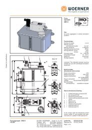
<strong>Reciprocating</strong> <strong>pump</strong> <strong>PMF</strong> / <strong>GMF</strong><br />
110.000<br />
EUG<strong>EN</strong> WOERNER GmbH & Co. KG<br />
Postfach 1661 DE-97866 Wertheim<br />
Am Eichamt 8 DE-97877 Wertheim<br />
Tel. +49 (0) 9342 803-0 info@woerner.de<br />
Fax.+49 (0) 9342 803-202 www.woerner.de<br />
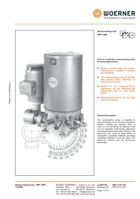
<strong>Reciprocating</strong> <strong>pump</strong><br />
<strong>PMF</strong> / <strong>GMF</strong><br />
This is a multi-line reciprocating <strong>pump</strong><br />
for many applications<br />
�<br />
�<br />
�<br />
�<br />
Being a universal type, our reciprocating<br />
<strong>pump</strong> is capable of meeting<br />
any challenge.<br />
The reciprocating <strong>pump</strong> can be fitted<br />
with various drives. Direction of<br />
rotation is as needed.<br />
Based on our long-standing<br />
experience, we can determine the<br />
appropriate type for every application.<br />
<strong>Reciprocating</strong> <strong>pump</strong>s can be used<br />
with oil and grease.<br />
General description:<br />
The reciprocating <strong>pump</strong> is capable of<br />
accommodating up to 24 <strong>pump</strong> elements.<br />
Delivery volume per element each is<br />
0,08 or 0,15 cm³/stroke at maximum and<br />
can be regulated continuously. Maximum<br />
operating pressure amounts to 350 bar. The<br />
reservoirs are made of steel sheet or<br />
transparent polyester material providing<br />
capacities between 2 and 30 litres. The<br />
reservoir content can be monitored<br />
electrically.<br />
Leaflet-No. 9002.10.07 <strong>EN</strong><br />
Replaces No. 9002.05.07 <strong>EN</strong><br />
Page 1 of 10
1<br />
3<br />
9<br />
7<br />
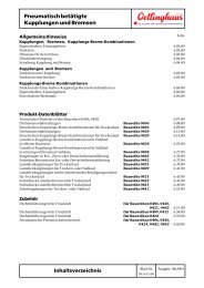
<strong>PMF</strong> <strong>pump</strong> elements assembly:<br />
When fitting another <strong>pump</strong> element into the<br />
reciprocating <strong>pump</strong>, please proceed as<br />
shown in the sketch beside: With the<br />
delivery piston being approximately pulled<br />
out half, insert the <strong>pump</strong> element diagonally<br />
upward into the casing's reception hole.<br />
Insertion and operation will be easier when<br />
the hole that serves to accommodate the<br />
delivery piston is filled with grease. Do not<br />
put the <strong>pump</strong> element into horizontal<br />
position and screw in, unless the delivery<br />
piston's head touches the pressure ring and<br />
ratches into the latter's groove.<br />
When demounting, pull the <strong>pump</strong> element<br />
cautiously out of the casing such that the<br />
delivery piston will remain within the <strong>pump</strong><br />
element.<br />
EUG<strong>EN</strong> WOERNER GmbH & Co. KG<br />
Postfach 1661 DE-97866 Wertheim<br />
Am Eichamt 8 DE-97877 Wertheim<br />
Tel. +49 (0) 9342 803-0 info@woerner.de<br />
Fax.+49 (0) 9342 803-202 www.woerner.de<br />
4<br />
5<br />
6<br />
8<br />
2<br />
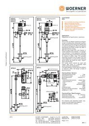
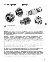
Mode of operation:<br />
The reciprocating <strong>pump</strong> is composed of the<br />
following main parts:<br />
The <strong>pump</strong> casing 2, the <strong>pump</strong> elements 9,<br />
the inner and outer drives 7, 8,<br />
and the<br />
reservoir 1.<br />
From the outer drive, the <strong>pump</strong><br />
shaft 5 is driven via a worm gear 7, 8.<br />
With<br />
this <strong>pump</strong> shaft 5, a pressure ring 6 runs<br />
around eccentrically, into which the <strong>pump</strong><br />
elements 9 are hooked. Due to the<br />
eccentricity of pressure ring 6 to the <strong>pump</strong><br />
shaft, every delivery piston will inevitably<br />
make a steady pressure and suction stroke<br />
with every turn of <strong>pump</strong> shaft 5.<br />
For <strong>pump</strong><br />
elements description, see: <strong>pump</strong> elements<br />
mode of operation, please. Pump shaft 5 is<br />
connected with a stirring mechanism 3 that<br />
presses the lubricant to the intake holes of<br />
the <strong>pump</strong> elements 9 and cuts air bubbles<br />
up. In the level monitor fitted version, a<br />
follow-up piston for grease usage is<br />
provided for. This piston rests on the grease<br />
surface, thus enabling precise level<br />
monitoring. If there is no level monitoring<br />
provided for, a stripper 4 is installed.<br />
Notes to operation:<br />
<strong>Reciprocating</strong> <strong>pump</strong>s must be operated<br />
with clean oil or grease from original drums<br />
only. If, upon start-up, filling is not made via<br />
the filling nipple, the <strong>pump</strong>, in case of initial<br />
filling, has to be filled with gear oil up to the<br />
stirrer wing's level. This way, proper<br />
deaeration is ensured. The lubricant leads<br />
must be cleaned and have no obstructions.<br />
They shall not be con-nected with the<br />
lubrication points, unless lubricant comes<br />
out free of bubbles. All delivery pipe<br />
connections should be checked for<br />
leakage.<br />
Leaflet-No. 9002 <strong>EN</strong><br />
Page 2 of 10<br />
- Subject to modifications -
- Subject to modifications -<br />
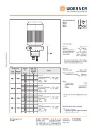
Suction stroke<br />
Pressure stroke<br />
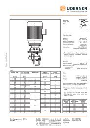
Pump elements mode of operation:<br />
Suction stroke is accomplished by delivery<br />
piston 1 and control piston 2.<br />
In this<br />
process, delivery piston 1 is actuated by the<br />
eccentric shaft, whilst the spring actuates<br />
control piston 2.<br />
The control piston closes<br />
pressure hole 3 and is kept in a certain<br />
position as determined by the preset<br />
delivery volume. The delivery piston moves<br />
on, causing a vacuum to be built up in the<br />
proportioning space. When the delivery<br />
piston has opened suction hole 4,<br />
lubricant<br />
starts to be sucked from the reservoir.<br />
In case of pressure stroke,<br />
delivery piston<br />
1 moves to the left. In this motion, suction<br />
hole 4 is closed and control piston 2<br />
displaced by virtue of the lubricant being<br />
available in between the delivery and<br />
control pistons until it releases pressure<br />
6<br />
7<br />
5<br />
hole 3 and the lubricant is delivered through<br />
the delivery piston to the outlet. The <strong>pump</strong><br />
elements are delivered with maximum<br />
delivery volume, i.e. they are set to full<br />
stroke.<br />
The delivery volume can be adjusted<br />
continuously between 25 and 100% of the<br />
nominal delivery volume. After having<br />
removed lock screw 7,<br />
the stroke is to be<br />
changed by means of the enclosed spanner<br />
through adjustment nipple 6.<br />
When turning<br />
the nippe to the right, delivery volume will<br />
decrease. At the adjustment nipple, there is<br />
a hexagon against which a spring loaded<br />
piston is pressing radially. Thus, any<br />
independent change of the delivery volume<br />
will be prevented. At the same time, the<br />
latching serves as a measure for setting the<br />
delivery volume.<br />
EUG<strong>EN</strong> WOERNER GmbH & Co. KG<br />
Postfach 1661 DE-97866 Wertheim<br />
Am Eichamt 8 DE-97877 Wertheim<br />
Tel. +49 (0) 9342 803-0 info@woerner.de<br />
Fax.+49 (0) 9342 803-202 www.woerner.de<br />
R<br />
3<br />
Delivery volume<br />
2<br />
4<br />
Six latches equal one rotation of the<br />
adjustment nipple and a reduction of the<br />
nominal delivery volume by 33%. 14 latches<br />
(minimum) equal a delivery volume<br />
reduction down to 25% of the nominal<br />
delivery volume.<br />
The element having a piston diameter of<br />
8 mm = 0,15 cm³/stroke is marked with a<br />
red ring "R".<br />
Leaflet-No. 9002 <strong>EN</strong><br />
Page 3 of 10<br />
1
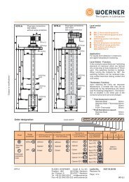
<strong>GMF</strong>-A<br />
<strong>GMF</strong>-C<br />
2<br />
12 2<br />
1<br />
13<br />
11<br />
10<br />
20<br />
9<br />
for M8<br />
for M8<br />
3<br />
14<br />
1<br />
4<br />
15<br />
5<br />
16<br />
6<br />
17<br />
7<br />
18<br />
8<br />
19<br />
<strong>GMF</strong>-B<br />
<strong>GMF</strong>-D<br />
22<br />
1<br />
10<br />
2<br />
9<br />
11<br />
1<br />
12 2 13<br />
24<br />
23<br />
21<br />
10<br />
20<br />
9<br />
for M8<br />
3<br />
8<br />
for M8<br />
4<br />
7<br />
3<br />
14<br />
4<br />
5<br />
6<br />
5<br />
16<br />
6<br />
17<br />
7<br />
18<br />
8<br />
19<br />
EUG<strong>EN</strong> WOERNER GmbH & Co. KG<br />
Postfach 1661 DE-97866 Wertheim<br />
Am Eichamt 8 DE-97877 Wertheim<br />
Tel. +49 (0) 9342 803-0 info@woerner.de<br />
Fax.+49 (0) 9342 803-202 www.woerner.de<br />
15<br />
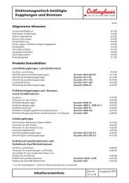
Type designation:<br />
Motor-driven reciprocating <strong>pump</strong>s are<br />
type-designated by <strong>GMF</strong>.<br />
The type designation of reciprocating<br />
<strong>pump</strong>s without motor-drive is <strong>PMF</strong>.<br />
Depending on the number of <strong>pump</strong> element<br />
installation points, additional distinction is<br />
made as follows:<br />
Number of<br />
mountable elements<br />
at maximum 2<br />
at maximum 10<br />
at maximum 20<br />
at maximum 24<br />
General technical data:<br />
Type<br />
<strong>GMF</strong>-A<br />
<strong>PMF</strong>-A<br />
<strong>GMF</strong>-B<br />
<strong>PMF</strong>-B<br />
<strong>GMF</strong>-C<br />
<strong>PMF</strong>-C<br />
<strong>GMF</strong>-D<br />
<strong>PMF</strong>-D<br />
Admissible delivery pressure: 350 bar<br />
Number of elements: 1 ... 24<br />
Delivery volume per stroke and element<br />
in case of <strong>pump</strong> element 6: 0,08 cm³<br />
in case of <strong>pump</strong> element 8: 0,15 cm³<br />
Stroke numbers of elements: 1 ... 25 min<br />
in case of deviation, please enquire<br />
Temperature range<br />
with electric motor: -20 ... +40 °C<br />
without electric motor: -20 ... +80 °C<br />
In the presence of low temperatures,<br />
grease penetration should be<br />
observed!<br />
Medium: Oil and grease<br />
up to NLGI-class 3<br />
When choosing the reservoir and level<br />
monitoring, the medium should be<br />
taken into account<br />
Lubricant: The intended lubricant must be<br />
suitable for use with centralized lubrication<br />
equipment.<br />
Drive direction of rotation: as needed<br />
<strong>Reciprocating</strong> <strong>pump</strong><br />
installation position: vertical<br />
Material:<br />
Casing: Aluminium<br />
Pump element: Steel, galvanised<br />
Reservoir 2, 4, 7, 25l: Steel,<br />
Reservoir 5, 10, 30l: Polyester<br />
Gaskets: NBR<br />
Leaflet-No. 9002 <strong>EN</strong><br />
Page 4 of 10<br />
-1<br />
galvanised<br />
- Subject to modifications -
- Subject to modifications -<br />
Steel sheet Polyester transparent<br />
2l<br />
4l<br />
7l<br />
25l<br />
5l<br />
10l<br />
30l<br />
EUG<strong>EN</strong> WOERNER GmbH & Co. KG<br />
Postfach 1661 DE-97866 Wertheim<br />
Am Eichamt 8 DE-97877 Wertheim<br />
Tel. +49 (0) 9342 803-0 info@woerner.de<br />
Fax.+49 (0) 9342 803-202 www.woerner.de<br />
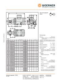
Reservoir:<br />
Reservoirs with capacities ranging between<br />
2l and 30l are available for delivery. Every<br />
<strong>pump</strong> type any of the reservoirs depicted<br />
can be assigned to.<br />
When choosing a reservoir, level monitoring<br />
and lubricant should be taken into<br />
consideration as well.<br />
Reservoir materials:<br />
Capacity Material Weight<br />
2 l<br />
1,0 kg<br />
4 l Steel, 1,4 kg<br />
7 l galvanised 2,0 kg<br />
25 l<br />
4,6 kg<br />
5 l Polyester, 1,5 kg<br />
10 l fibreglass 1,8 kg<br />
30 l reinforced 4,0 kg<br />
Reservoirs and level monitoring<br />
capability:<br />
Capacity Level monitoring<br />
2 l<br />
4 l<br />
7 l<br />
25 l<br />
5 l<br />
10 l<br />
30 l<br />
Leaflet-No. 9002 <strong>EN</strong><br />
Page 5 of 10<br />
impossible<br />
for oil: Float switch<br />
min. level<br />
for oil: Float switch<br />
min. and max. level<br />
for oil: Float switch<br />
min. and max. level<br />
for grease: Follow-up piston<br />
min. and max. level<br />
When a follow-up piston is used, the<br />
utilisable reservoir volume is reduced as<br />
follows<br />
Reservoir capacity 5 l and 10 l<br />
by approx. 2,5 l<br />
Reservoir capacity 30 l by approx. 6,0 l<br />
For further information, see "level monitoring"<br />
description
Drive types:<br />
Drive "M" Drive "N" Drive "L"<br />
Drive "M":<br />
Drive "N":<br />
with gear and motor<br />
BG63<br />
with gear and motor<br />
BG71<br />
Weight [kg]: 10,7 + reservoir weight+<br />
0,25 x number of elements<br />
The gears are filled with 80 cm³ ISO VG 220<br />
gear oil. After 3000 hours of operation,<br />
checking is required.<br />
Overall<br />
transmission<br />
60 : 1<br />
97 : 1<br />
160 : 1<br />
316 : 1<br />
625 : 1<br />
1250 : 1<br />
2500 : 1 �<br />
� on request only<br />
Delivery flow<br />
per element [cm³/min]<br />
Element Ø6 Element Ø8<br />
1,82<br />
1,12<br />
0,67<br />
0,34<br />
0,17<br />
0,087<br />
0,0435<br />
3,4<br />
2,1<br />
1,28<br />
0,64<br />
0,32<br />
0,163<br />
0,0815<br />
max. operating pressure [bar] (with 20 elements installed)<br />
Drive "M"<br />
Drive "N"<br />
Element Ø6 Element Ø8 Element Ø6 Element Ø8<br />
230 100<br />
200<br />
330 170<br />
270<br />
320 350<br />
350<br />
Motor electrical data:<br />
Mains voltage: 230 / 400 V<br />
Frequency: 50 Hz<br />
Special voltage and frequency possible<br />
Synchronous speed: 1500 min<br />
Power:<br />
Drive "M": 0,18 kW<br />
Drive "N": 0,37 kW<br />
Protection system: IP55<br />
Thermal category: F<br />
350<br />
350<br />
EUG<strong>EN</strong> WOERNER GmbH & Co. KG<br />
Postfach 1661 DE-97866 Wertheim<br />
Am Eichamt 8 DE-97877 Wertheim<br />
Tel. +49 (0) 9342 803-0 info@woerner.de<br />
Fax.+49 (0) 9342 803-202 www.woerner.de<br />
-1<br />
Drive "L": with gear and hydraulic<br />
motor<br />
Weight [kg]: 7,7 + reservoir weight+<br />
0,25 x number of elements<br />
Overall reduction same as with drives<br />
"M", "N"<br />
Motor technical data:<br />
When oil flow is 3,5 l/min<br />
Power: 0,25 kW<br />
Speed:<br />
-1<br />
400 min<br />
Speed max.: 1950 min<br />
Pressure inclination max.: 100 bar<br />
Oil flow max.: 16 l/min<br />
mind permissible element stroke<br />
number!<br />
The gears are filled with 80 cm³ ISO VG 220<br />
gear oil. After 3000 hours of operation,<br />
checking is required.<br />
Leaflet-No. 9002 <strong>EN</strong><br />
Page 6 of 10<br />
-1<br />
- Subject to modifications -
- Subject to modifications -<br />
Drive "V"<br />
Drive "P"<br />
Drive "V": with gear<br />
Weight [kg]: 6,4 + reservoir weight+<br />
0,25 x number of elements<br />
Transmissions:<br />
97 : 1<br />
625 : 1<br />
3300 : 1<br />
The gears are filled with 80 cm³ ISO VG 220<br />
gear oil. After 3000 hours of operation,<br />
checking is required.<br />
Drive "P":<br />
160 : 1<br />
1250 : 1<br />
4356 : 1<br />
316 : 1<br />
2500 : 1<br />
without gear, for spare parts<br />
keeping<br />
Gears ZAF following leaflet-no. 0380 can<br />
be mounted on. Hence, <strong>pump</strong>s with the<br />
drives "M", "N" or "V" are generated.<br />
Drive "O" Drive "R"<br />
Drive "U"<br />
Drive "K"<br />
Drive "O": oscillating<br />
Weight [kg]: 6,8 + reservoir weight+<br />
0,25 x number of elements<br />
Transmissions:<br />
1,33 : 1<br />
4,25 : 1<br />
25 : 1<br />
1,78 : 1 2,33 : 1<br />
7,66 : 1<br />
50 : 1<br />
Formula for eccentric stroke<br />
calculation: 2 x L x � x n1 x i<br />
h =<br />
n<br />
12,7 : 1<br />
66 : 1<br />
h = Eccentric stroke [mm]<br />
L = Swivel lever length [mm]<br />
n 1=<br />
Stroke number of <strong>pump</strong> elements<br />
-1<br />
[min ]<br />
i = Transmission<br />
n = Speed of the driving shaft<br />
EUG<strong>EN</strong> WOERNER GmbH & Co. KG<br />
Postfach 1661 DE-97866 Wertheim<br />
Am Eichamt 8 DE-97877 Wertheim<br />
Tel. +49 (0) 9342 803-0 info@woerner.de<br />
Fax.+49 (0) 9342 803-202 www.woerner.de<br />
1 2<br />
Drive "R": long driving shaft 1<br />
Drive "U": short driving shaft 2<br />
Drive "K": for coupling of 2 <strong>PMF</strong><br />
driving shaft 2 and 3<br />
Weight [kg]: 5,2 + reservoir weight+<br />
0,25 x number of elements<br />
Transmissions:<br />
1,33 : 1<br />
4,25 : 1<br />
25 : 1<br />
Leaflet-No. 9002 <strong>EN</strong><br />
Page 7 of 10<br />
1,78 : 1<br />
7,66 : 1<br />
50 : 1<br />
3<br />
2,33 : 1<br />
12,7 : 1<br />
66 : 1
Level monitoring via<br />
level switch "S"<br />
Level monitoring via<br />
level switch with<br />
follow-up piston "K"<br />
Float atop<br />
(full reservoir)<br />
Float on bottom<br />
(empty reservoir)<br />
Follow-up piston<br />
atop<br />
(full reservoir)<br />
Follow-up piston<br />
on bottom<br />
(empty reservoir)<br />
EUG<strong>EN</strong> WOERNER GmbH & Co. KG<br />
Postfach 1661 DE-97866 Wertheim<br />
Am Eichamt 8 DE-97877 Wertheim<br />
Tel. +49 (0) 9342 803-0 info@woerner.de<br />
Fax.+49 (0) 9342 803-202 www.woerner.de<br />
Level monitoring:<br />
Electrical data:<br />
Switching power at max.: 40 W / 60 VA<br />
Switching voltage at max.: 230 VUC<br />
Switching current at max.: 0,5A<br />
In case of inductive and capacitive<br />
loads, protective switchings should be<br />
provided for (diode, RC-element,<br />
varistor)<br />
Protection system: IP 65<br />
Connection type: Screw terminals<br />
Cable gland: PG11<br />
Conductor cross secton: 0,5...1,5 mm²<br />
Weight: 0,15 ... 0,18 kg<br />
Connection diagram:<br />
black<br />
orange<br />
blue<br />
black<br />
orange<br />
blue<br />
black<br />
orange<br />
blue<br />
Leaflet-No. 9002 <strong>EN</strong><br />
Page 8 of 10<br />
grey<br />
red<br />
brown<br />
grey<br />
red<br />
brown<br />
grey<br />
red<br />
brown<br />
full<br />
reservoir<br />
empty<br />
reservoir<br />
Level switches with follow-up pistons can<br />
be fitted into polyester-made reservoirs<br />
only.<br />
Follow-up piston weight<br />
for reservoir: 5 a. 10 l = 0,8 kg<br />
for reservoir: 30 l = 2,7 kg<br />
- Subject to modifications -
- Subject to modifications -<br />
Auxiliaries<br />
Filling connector:<br />
Purchase-no. Depiction Mounting place Use<br />
Locking nipple "V"<br />
with dust cap<br />
110.125-65<br />
Locking coupling<br />
with dust plug<br />
110.135-65<br />
Filling nipple<br />
(U 30) "B"<br />
110.550-66<br />
Pressure control valve:<br />
Purchase-no. Opening pressure [bar] Depiction Mounting place Use<br />
110.566-65<br />
110.564-65<br />
110.560-65<br />
110.568-65<br />
110.562-65<br />
Manometer connector:<br />
110.068-65<br />
Adjustment spanner:<br />
70 bar<br />
150 bar<br />
400 bar<br />
preset as per customer's<br />
specification:<br />
from 50 to 160<br />
from 160 to 250<br />
After removal of the<br />
locking screw at the<br />
<strong>pump</strong> element, the<br />
pressure control valve<br />
can be screwed in.<br />
Purchase-no. Depiction Use<br />
110.004-45<br />
Locking nipple DN6<br />
Tube � 12<br />
Locking coupling DN6<br />
Instead of a<br />
<strong>pump</strong> element<br />
The locking coupling<br />
serves to establish a<br />
connection between<br />
the locking nipple and<br />
the hose.<br />
Instead of a<br />
<strong>pump</strong> element<br />
Leaflet-No. 9002 <strong>EN</strong><br />
Page 9 of 10<br />
To limit max.<br />
operating pressure.<br />
Purchase-no. Depiction<br />
Mounting place Use<br />
EUG<strong>EN</strong> WOERNER GmbH & Co. KG<br />
Postfach 1661 DE-97866 Wertheim<br />
Am Eichamt 8 DE-97877 Wertheim<br />
Tel. +49 (0) 9342 803-0 info@woerner.de<br />
Fax.+49 (0) 9342 803-202 www.woerner.de<br />
After removal of the<br />
locking cap at the<br />
<strong>pump</strong> element, the<br />
manometer connector<br />
can be screwed in.<br />
for reservoir filling<br />
To connect a<br />
manomter with<br />
G 1/4" male thread.<br />
After removal of the locking cap at the <strong>pump</strong><br />
element, the delivery volume of the <strong>pump</strong><br />
element can be adjusted by using the adjustment<br />
spanner ( included in scope of delivery<br />
= i.e. 1 piece per <strong>pump</strong> each)
Purchase-designation:<br />
<strong>Reciprocating</strong> <strong>pump</strong><br />
Reservoir Overall<br />
Element 6<br />
Element 8<br />
Type<br />
Drive<br />
capacity [l] reduc-<br />
with pipe connection with pipe connection<br />
type<br />
with motor without motor Polyester Steel tion<br />
� 6 � 8 � 10 � 6 � 8 � 10<br />
1) Any <strong>GMF</strong>-A/B/C/D version possible in case of drive M, N or L only!<br />
2) When element installation in a certain position is required, please state<br />
such position when ordering! For instance: In case of 6 elements:<br />
"Installation into positions 1...3 and 7...9".<br />
3) Instead of an element, a filling connector can be installed!<br />
4) All element-free connections must be closed with lock screws!<br />
5) Level monitoring "K" and "F" possible in case of polyester reservoirs only!<br />
Purchase-example:<br />
Pump <strong>PMF</strong>-B, reservoir 10l, overall reduction 1,33 (acc. to table), drive type U, 5 pieces of element 6 with pipe connector 8, 2 pieces of<br />
element 8 with pipe connector 6, filling connector V, 2 lock screws, level monitoring "S".<br />
Purchase-designation:<br />
<strong>PMF</strong>-B.B / 10 / 1,33 / U / 0 / 5 / 0 / 2 / 0 / 0 / V / 2 / S<br />
Overall<br />
reduction table<br />
3300<br />
4356<br />
Filling<br />
connection<br />
Leaflet-No. 9002 <strong>EN</strong><br />
Page 10 of 10<br />
V M N L<br />
97<br />
160<br />
316<br />
625<br />
1250<br />
2500<br />
Lock screw<br />
60<br />
Number<br />
State voltage<br />
and frequency,<br />
please.<br />
O K R U P<br />
1,33<br />
1,78<br />
2,33<br />
4,25<br />
7,66<br />
12,7<br />
25<br />
50<br />
66<br />
Level<br />
monitoring<br />
see 1) see 2) see 2) see 2) see 2) see 2) see 2) see 3) see 4) see 5)<br />
<strong>GMF</strong>-A<br />
(2 places)<br />
<strong>GMF</strong>-B<br />
(10 places)<br />
<strong>GMF</strong>-C<br />
(20 places)<br />
<strong>GMF</strong>-D<br />
(24 places)<br />
internal<br />
<strong>PMF</strong>-A<br />
(2 places)<br />
<strong>PMF</strong>-B<br />
(10 places)<br />
<strong>PMF</strong>-C<br />
(20 places)<br />
<strong>PMF</strong>-D<br />
(24 places)<br />
5<br />
10<br />
30<br />
.<br />
B<br />
2<br />
4<br />
7<br />
25<br />
see<br />
table<br />
V<br />
M<br />
N<br />
L<br />
O<br />
K<br />
R<br />
U<br />
P<br />
Number Number Number Number Number Number<br />
0 � 2<br />
0 � 10<br />
0 � 20<br />
0 � 2<br />
0 � 10<br />
0 � 20<br />
0 � 2<br />
0 � 10<br />
0 � 20<br />
0 � 2<br />
0 � 10<br />
0 � 20<br />
0 � 2<br />
0 � 10<br />
together 10 elements possible at maximum!<br />
0 � 20<br />
0 � 2<br />
0 � 10<br />
�������������������<br />
Number Number Number Number Number Number<br />
together 20 elements possible at maximum!<br />
0 � 20<br />
�������������������<br />
Number Number Number Number Number Number<br />
0 � 24 0 � 24 0 � 24 0 � 24 0 � 24 0 � 24<br />
�������������������<br />
together 24 elements possible at maximum!<br />
with<br />
B<br />
with<br />
V<br />
0 �<br />
������������������� at max. 2<br />
together 2 elements possible at maximum! without<br />
0<br />
Number Number Number Number Number Number<br />
EUG<strong>EN</strong> WOERNER GmbH & Co. KG<br />
Postfach 1661 DE-97866 Wertheim<br />
Am Eichamt 8 DE-97877 Wertheim<br />
Tel. +49 (0) 9342 803-0 info@woerner.de<br />
Fax.+49 (0) 9342 803-202 www.woerner.de<br />
:<br />
2<br />
0<br />
without level<br />
monitoring<br />
0 � 10 Grease K<br />
at max. 10<br />
with level<br />
switch and<br />
follow-up<br />
piston<br />
0 �<br />
Grease F<br />
20<br />
with follow-<br />
at max. 20 up piston,<br />
without<br />
level switch<br />
Oil S<br />
0 � 24<br />
with level<br />
at max. 24 switch without<br />
follow-up<br />
piston<br />
- Subject to modifications -