Steel Doors & Frames - Fleming Door Products
Steel Doors & Frames - Fleming Door Products
Steel Doors & Frames - Fleming Door Products

You also want an ePaper? Increase the reach of your titles
YUMPU automatically turns print PDFs into web optimized ePapers that Google loves.
<strong>Steel</strong> <strong><strong>Door</strong>s</strong> & <strong>Frames</strong>
PRINTED IN CANADA<br />
INTRODUCTION<br />
FOREWORD<br />
Welcome to the commercial steel door and frame industry. We at <strong>Fleming</strong> <strong>Door</strong> <strong>Products</strong><br />
Ltd. are proud and privileged to have you on our team of professionals in the nonresidential<br />
steel door and frame industry.<br />
This manual is designed to give you an understanding of exciting and profitable product<br />
lines which, in many instances, sell themselves by virtue of their strength, durability,<br />
versatile application and building or life safety code requirements, which after all, are the<br />
back bone of every building.<br />
This “Basic Hollow Metal Training Manual” (Third Edition), is a starting point and a<br />
reference guide to provide you with a working knowledge of steel doors, frames and,<br />
because of their inter-relationship, builders’ hardware.<br />
The manual has been formatted in the following sections;<br />
• Forward<br />
• Table of Contents and Illustrations<br />
• <strong>Steel</strong> <strong>Door</strong> <strong>Frames</strong><br />
• Hollow Metal <strong><strong>Door</strong>s</strong><br />
• Builders’ Hardware<br />
• Estimating and Ordering<br />
• Glossary and Abbreviations<br />
• Index<br />
• Catalogues<br />
The Forward, Table of Contents and Table of Illustrations are provided as an over-view for<br />
quick reference. The Frame, <strong>Door</strong> and Hardware sections are extensively illustrated with<br />
over 230 drawings and tables. Following the Estimating and Ordering section are a<br />
Glossary, Abbreviations, a comprehensive Index for the Manual and both our <strong>Steel</strong> <strong>Door</strong><br />
and Frame Catalogue and the <strong>Fleming</strong> Fire Labeling Specifications brochure.<br />
To provide you with support and assistance, our industry renowned Customer Support,<br />
Engineering and Technical Services people are there for you, just a 1-800 (263-7515) call<br />
away.<br />
To augment your training <strong>Fleming</strong> also offers other basic, intermediate and advanced level<br />
factory seminars and programs, designed to target specific areas of specialization.<br />
This manual, like everything else at <strong>Fleming</strong>, is the result of the combined efforts of our<br />
sales, marketing, engineering and manufacturing groups. The manual was developed by<br />
Bud Bulley, our Manager for Technical Services. Your comments or suggestions are<br />
appreciated and welcomed. Any questions you have can be directed his way.<br />
Page<br />
F 1<br />
Date<br />
Mar ‘05
PRINTED IN CANADA<br />
HISTORY<br />
FOREWORD<br />
<strong>Fleming</strong> <strong>Door</strong> <strong>Products</strong> was originally incorporated January 1 st , 1959. Our founder, Sam<br />
<strong>Fleming</strong>, started in a 1,250 square foot building in Scarborough, a suburb of Toronto and<br />
set about<br />
establishing his reputation as a premier custom sheet metal fabricator.<br />
Originally <strong>Fleming</strong> manufactured a variety of sheet metal and stainless steel products,<br />
including toilet partitions, lockers, pre-fabricated fireplaces, drafting tables, commercial<br />
coolers and freezers, louvers, vents, polio vaccine vessels, radar equipment, storage<br />
tanks, hoppers and nuclear fuel containers, along with steel doors and frames.<br />
In 1963 the company moved to a larger plant which initially covered 30,000 square feet.<br />
Over the ensuing years, this building would be expanded several times, two other<br />
buildings were added, totaling 108,000 square feet of office, manufacturing and<br />
warehouse space.<br />
By the mid-60’s <strong>Fleming</strong> had reduced the product lines to include only steel doors, frames<br />
and toilet partitions. In 1978 the toilet partition division was sold in order to concentrate<br />
exclusively on our core business, steel doors and frames.<br />
We began in the non-residential market as a small, custom manufacturer, providing<br />
product only in greater Toronto. A combination of quality, product depth and service<br />
allowed <strong>Fleming</strong> to grow into the largest supplier in the area.<br />
In the early 1970’s, after establishing ourselves in Toronto, <strong>Fleming</strong> instituted a national<br />
marketing program through stocking distributors, who perform final fabrication and sell<br />
directly to General Contractors. Between 1973 and 1986 the <strong>Fleming</strong> team grew to<br />
include distributors in every major Canadian city and today we are the largest<br />
manufacturer of non-residential steel doors and frames in the country. As a testament to<br />
our commitment and their success, our original group of Canadian distributors continue to<br />
represent <strong>Fleming</strong> to this day.<br />
In 1986 <strong>Fleming</strong> launched into the United States and overseas markets. With our team of<br />
factory and manufacturer representatives and distributors throughout the US, we are a<br />
serious force and significant supplier in most major cities. <strong>Fleming</strong> also has distributors in<br />
the Middle East, Asia, the United Kingdom, the Caribbean and Mexico.<br />
At the same time, to support and ensure continued growth, planning began for new Head<br />
Office and manufacturing facilities. In 1987 our state-of-the-art, 140,000 square foot plant<br />
opened in Ajax, Ontario, just east of Toronto. Sitting on 9½ acres of prime industrial<br />
property, we have the potential to almost double our existing manufacturing space to meet<br />
customer demands.<br />
Page<br />
F 2<br />
Date<br />
Mar ‘05
PRINTED IN CANADA<br />
FOREWORD<br />
<strong>Fleming</strong>’s reputation as one of North America’s fastest growing steel door and frame<br />
manufacturers is based on our commitment to quality, service, research and development<br />
and leading edge technology.<br />
Our senior executives, management group, engineering, customer support and<br />
administrative staff are all career professionals. The depth of industry specific experience<br />
is unrivalled. Our management team averages 28+ years, engineering and customer<br />
support are 21+ years and the shop floor is 18+ years, with over 20% having 20 years or<br />
more with the company. For you, it means a stable, knowledgeable support network.<br />
The use of CAD/CAM and real-time production planning affords the <strong>Fleming</strong> team the best<br />
delivery lead-times in the industry at competitive prices. The latest production equipment<br />
and processes, in-plant, engineering and order-entry automation, bound together under<br />
our ISO 9001:2000 Registered Quality Management System, allows <strong>Fleming</strong> to provide<br />
the highest quality product, support and service available.<br />
You will be drawing on over forty-five years of manufacturing experience, an exceptional<br />
product line, on-going research, development and quality programs, with service and<br />
support from committed and professional in-house staff, factory and manufacturers reps.<br />
Together with our international network of stocking distributors, we have established<br />
ourselves as world leaders in the commercial, industrial and institutional steel door and<br />
frame market.<br />
As you begin your journey of learning and growth, we wish you every success and are<br />
here to encourage and support your continued efforts.<br />
Thank you for joining our team.<br />
FLEMING DOOR PRODUCTS LTD<br />
Page<br />
F 3<br />
Date<br />
Mar ‘05
PRINTED IN CANADA<br />
TABLE OF CONTENTS<br />
Foreword<br />
Introduction ........................................................................................................ F1<br />
History ............................................................................................................... F2<br />
Table of Contents ..................................................................................................... i<br />
Table of Illustrations ............................................................................................... iv<br />
<strong>Steel</strong> <strong>Door</strong> <strong>Frames</strong><br />
Galvanneal <strong>Steel</strong> ................................................................................................ 1<br />
Definitions ........................................................................................................... 7<br />
Components ....................................................................................................... 8<br />
Profiles<br />
Types .......................................................................................................... 11<br />
Terminology ................................................................................................ 14<br />
Assembly Methods<br />
Knocked-Down .......................................................................................... 22<br />
Knocked-Down Slip-On Drywall ................................................................. 23<br />
Set-Up and Welded ................................................................................... 24<br />
Walls and Anchors .............................................................................................. 25<br />
Masonry ..................................................................................................... 27<br />
Drywall<br />
<strong>Steel</strong> Stud .......................................................................................... 31<br />
Wood Stud ......................................................................................... 36<br />
Existing ...................................................................................................... 40<br />
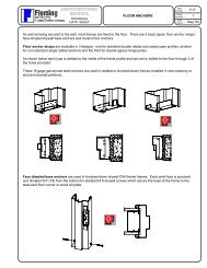
Floor Anchors .................................................................................................... 42<br />
Hardware Preparations<br />
Standard Locations .................................................................................... 46<br />
Reinforcings ............................................................................................... 47<br />
Handing ............................................................................................................ 54<br />
<strong>Fleming</strong> Frame Series<br />
F-Series (Masonry) .................................................................................... 60<br />
DW-Series (Drywall) .................................................................................. 62<br />
DE-Series (Double Egress) ....................................................................... 64<br />
A-Series (Adjustable) .................................................................................. 67<br />
MN-Series (Miter & Notch) & ST-Series (Sticks) ....................................... 69<br />
Fire Rated Frame Product ................................................................................. 71<br />
Installation<br />
Welded and Knocked-Down <strong>Frames</strong> ......................................................... 75<br />
DW-Series Knocked-Down Drywall <strong>Frames</strong> .............................................. 82<br />
A-Series Knocked-Down <strong>Frames</strong> .............................................................. 86<br />
Page<br />
i<br />
Date<br />
Mar ‘05
PRINTED IN CANADA<br />
TABLE OF CONTENTS<br />
Hollow Metal <strong><strong>Door</strong>s</strong><br />
Construction ....................................................................................................... 91<br />
Terminology ....................................................................................................... 92<br />
Features ............................................................................................................ 94<br />
Heads ........................................................................................................ 94<br />
Sills ............................................................................................................ 95<br />
Lock and Hinge Edges .............................................................................. 96<br />
<strong>Door</strong> Types ....................................................................................................... 100<br />
Hardware Preparations<br />
Standard Locations ................................................................................... 105<br />
Typical Applications .................................................................................. 109<br />
Reinforcings and Preparations ................................................................. 114<br />
<strong>Fleming</strong> <strong>Door</strong> Series<br />
D-Series (Lock Seam) .............................................................................. 120<br />
E-Series (6 Panel Embossed Lock Seam) ............................................... 122<br />
H-Series (Vertically Stiffened) ................................................................... 124<br />
Product Selection and Applications .................................................................. 126<br />
SDI 100 Comparisons ...................................................................................... 128<br />
Hollow Metal Fire <strong><strong>Door</strong>s</strong> ................................................................................... 129<br />
Builders’ Hardware<br />
Introduction ....................................................................................................... 131<br />
Hinges and Pivots ............................................................................................. 132<br />
Full Mortise ....................................................................................... 132<br />
Half Mortise ...................................................................................... 133<br />
Full Surface ...................................................................................... 133<br />
Half Surface ...................................................................................... 133<br />
Swing Clear ...................................................................................... 134<br />
Sizing ........................................................................................................ 134<br />
Special Purpose <strong>Products</strong><br />
Spring Hinges ................................................................................... 136<br />
Electric Hinges ................................................................................. 136<br />
Continuous Hinges ........................................................................... 137<br />
Anchor Hinges .................................................................................. 138<br />
Pivots ................................................................................................ 138<br />
Locks and Latches<br />
Terminology .............................................................................................. 141<br />
Cylindrical Locks ....................................................................................... 142<br />
Mortise Locks ........................................................................................... 144<br />
Cylindrical Deadlocks ............................................................................... 145<br />
Mortise Deadlocks .................................................................................... 146<br />
Interconnected Locks ............................................................................... 147<br />
Flush and Surface Bolts ........................................................................... 147<br />
Applications .............................................................................................. 149<br />
Page<br />
ii<br />
Date<br />
Mar ‘05
PRINTED IN CANADA<br />
TABLE OF CONTENTS<br />
Exit Devices ...................................................................................................... 151<br />
Panic Exit Devices .................................................................................... 152<br />
Fire Exit Devices ....................................................................................... 152<br />
Types<br />
Rim ................................................................................................... 153<br />
Mortise .............................................................................................. 153<br />
Surface Vertical Rod ......................................................................... 154<br />
Concealed Vertical Rod .................................................................... 155<br />
Applications .............................................................................................. 156<br />
Closers<br />
Surface ..................................................................................................... 159<br />
Regular Arm ..................................................................................... 160<br />
Parallel Arm ...................................................................................... 161<br />
Top Jamb Mounted ........................................................................... 162<br />
Concealed ................................................................................................ 163<br />
Concealed in Frame ......................................................................... 163<br />
Concealed in <strong>Door</strong> ............................................................................ 164<br />
Floor ................................................................................................. 165<br />
Holders and Stops ............................................................................................ 166<br />
Overhead Holders .................................................................................... 167<br />
Surface ............................................................................................. 167<br />
Concealed ........................................................................................ 168<br />
Combination Closer/Holder/Detectors .............................................................. 168<br />
Co-Ordinators ................................................................................................... 169<br />
Surface Applied Accessories ............................................................................ 169<br />
<strong>Door</strong> Pulls and Push Plates ...................................................................... 170<br />
Protective Plates ....................................................................................... 170<br />
Estimating and Ordering<br />
Take-Off ........................................................................................................... 172<br />
Summarize ....................................................................................................... 175<br />
Pricing .............................................................................................................. 175<br />
Ordering<br />
<strong>Frames</strong> ..................................................................................................... 175<br />
Transom, Sidelight and Window <strong>Frames</strong> .................................................. 180<br />
<strong><strong>Door</strong>s</strong> ........................................................................................................ 181<br />
Glossary ................................................................................................................. 186<br />
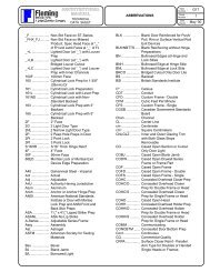
Abbreviations ........................................................................................................ 213<br />
Index ................................................................................................................... 217<br />
Catalogues<br />
<strong>Fleming</strong> <strong>Steel</strong> <strong><strong>Door</strong>s</strong> & <strong>Frames</strong><br />
<strong>Fleming</strong> Fire Labeling Specifications<br />
Page<br />
iii<br />
Date<br />
Mar ‘05
PRINTED IN CANADA<br />
Figure<br />
N o<br />
TABLE OF<br />
ILLUSTRATIONS<br />
Description Page<br />
1 Hot Strip Mill Process ............................................................................... 1<br />
2 Cold Strip Mill Process ............................................................................. 1<br />
3 Galvanizing Mill Process .......................................................................... 2<br />
4 Galvanneal, Galvanized and CRS Cross-Sections .................................. 3<br />
5 Typical Frame Elevations ......................................................................... 7<br />
6 Typical Transom Frame Elevations .......................................................... 7<br />
7 Typical Sidelight Frame Elevations .......................................................... 7<br />
8 Typical Borrowed Light and Window Elevations ...................................... 8<br />
9 Single Frame Components ...................................................................... 8<br />
10 Frame Components for Pairs ................................................................... 9<br />
11 4-Sided Frame Components .................................................................... 9<br />
12 Closed Sections ...................................................................................... 10<br />
13 Typical Sidelight Frame Components ..................................................... 10<br />
14 Double Rabbet Masonry Profile .............................................................. 11<br />
15 Double Rabbet Mullion ............................................................................ 11<br />
16 Single Rabbet Profiles ............................................................................ 12<br />
17 Drywall Profiles ....................................................................................... 12<br />
18 Cased Open Sections ............................................................................. 13<br />
19 Double Egress Sections .......................................................................... 13<br />
20 Mullion Profiles ....................................................................................... 14<br />
21 Jamb Depth ............................................................................................ 14<br />
22 Face ........................................................................................................ 15<br />
23 Opposite Face ........................................................................................ 15<br />
24 Returns ................................................................................................... 16<br />
25 Drywall Returns ...................................................................................... 16<br />
26 Throat Opening ....................................................................................... 17<br />
27 <strong>Door</strong> Rabbet ........................................................................................... 17<br />
28 Opposite Rabbet ..................................................................................... 18<br />
29 Soffit ........................................................................................................ 18<br />
30 Stop ........................................................................................................ 19<br />
31 Reveal ..................................................................................................... 19<br />
32 Reveal Rabbet ........................................................................................ 20<br />
33 Backset ................................................................................................... 20<br />
34 Gage ....................................................................................................... 20<br />
35 Profile Terminology Summary ................................................................. 21<br />
36 F-Series Knocked-Down <strong>Frames</strong> ............................................................ 22<br />
37 DW-Series Slip-On Knocked-Down Drywall <strong>Frames</strong> ............................... 23<br />
38 Set-Up and Welded <strong>Frames</strong> ................................................................... 24<br />
39 Typical Floor Plan ................................................................................... 25<br />
40 Typical Wall Details ................................................................................. 26<br />
41 Wrap Around Masonry Application ......................................................... 27<br />
42 Butted Masonry Application .................................................................... 28<br />
43 Masonry Wire Anchor ............................................................................. 29<br />
Page<br />
iv<br />
Date<br />
Mar ‘05
PRINTED IN CANADA<br />
Figure<br />
N o<br />
TABLE OF<br />
ILLUSTRATIONS<br />
Description Page<br />
44 Bridge and Strap Masonry Fire Anchor ................................................... 30<br />
45 Recommended Installation - <strong>Steel</strong> Studs at Jamb/Head Intersection ..... 32<br />
46 Typical <strong>Steel</strong> Stud and Drywall Partitions ............................................... 32<br />
47 Combination Stud Anchors ..................................................................... 33<br />
48 Z Anchor ................................................................................................. 34<br />
49 DW-Series Compression Anchor Assembly ............................................ 35<br />
50 A-Series Frame Face Dimpled Anchors – <strong>Steel</strong> Studs ........................... 35<br />
51 Typical Wood Stud Framed Opening ...................................................... 36<br />
52 Typical Wood Stud and Drywall Partitions .............................................. 37<br />
53 Combination Stud Anchors in Wood Stud Walls ..................................... 38<br />
54 Wood Stud Anchors ................................................................................ 39<br />
55 Wood Stud Installations .......................................................................... 39<br />
56 Typical Pre-Cast or Concrete Walls ........................................................ 40<br />
57 Butterfly Existing Wall Anchor Guide ...................................................... 41<br />
58 Strap and Channel Existing Wall Anchor Guide ...................................... 41<br />
59 A-Series Frame Face Dimpled Anchors – Existing Walls ....................... 42<br />
60 Floor Anchor Straps ................................................................................ 43<br />
61 KD-DW Series Face Dimpled Base Anchors .......................................... 44<br />
62 A-Series Face Dimpled Base Anchor ..................................................... 44<br />
63 Mullion Floor Anchors ............................................................................. 45<br />
64 Standard Hardware Locations ................................................................ 46<br />
65 High Frequency Hinge Reinforcing ......................................................... 47<br />
66 ASA Strike Reinforcing ........................................................................... 48<br />
67 Small ASA/NL Strike Reinforcing ............................................................ 49<br />
68 Surface Strike Reinforcing ...................................................................... 50<br />
69 Surface Closer Reinforcing ..................................................................... 51<br />
70 Parallel Arm Closer Reinforcing .............................................................. 52<br />
71 Reversible Flush Bolt Strike and Reinforcing .......................................... 53<br />
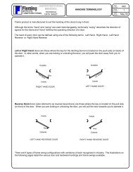
72 Right or Left Hand ................................................................................... 54<br />
73 Reverse Hand ......................................................................................... 54<br />
74 Handing - Singles (Single Acting) ........................................................... 55<br />
75 Handing – Pairs ...................................................................................... 56<br />
76 Handing - Double Egress ........................................................................ 56<br />
77 Handing – R/L, R/R, L/L .......................................................................... 57<br />
78 Handing - Contra-Swing .......................................................................... 57<br />
79 Handing - Double Acting ......................................................................... 58<br />
80 Handing - Communicating <strong>Frames</strong> ......................................................... 59<br />
81 Handing - Multi-Opening Units ................................................................ 59<br />
82 F-Series Standard Profiles and Sizes ..................................................... 61<br />
83 DW-Series Jamb, Head, Corner Details ................................................. 62<br />
84 DW-Series Standard Profiles and Sizes ................................................. 63<br />
85 DE-Series Frame Plan ............................................................................ 64<br />
86 DE-Series Frame Details ........................................................................ 65<br />
Page<br />
v<br />
Date<br />
Mar ‘05
PRINTED IN CANADA<br />
Figure<br />
N o<br />
TABLE OF<br />
ILLUSTRATIONS<br />
Description Page<br />
87 DE-Series Standard Profiles and Sizes .................................................. 66<br />
88 A-Series Standard Profiles and Sizes ..................................................... 68<br />
89 MN and ST-Series Standard Profiles ...................................................... 70<br />
90 Typical Sidelight Components ................................................................ 70<br />
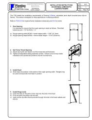
91-104 Welded and KD Frame Installation Instructions .................................... 75-81<br />
105-114 DW-Series Frame Installation Instructions ............................................ 82-86<br />
115-123 A-Series Frame Installation Instructions ............................................... 86-90<br />
124 Lock Seam <strong>Door</strong> Construction ................................................................ 91<br />
125 Vertically Stiffened <strong>Door</strong> Construction .................................................... 91<br />
126 <strong>Door</strong> Front and Back ............................................................................... 92<br />
127 <strong>Door</strong> Terminology ................................................................................... 93<br />
128 Standard Head Detail .............................................................................. 94<br />
129 Optional Exterior <strong>Door</strong> Head Details ....................................................... 94<br />
130 Optional Tack-Welded Top Cap .............................................................. 95<br />
131 Optional Rabbetted Top Cap .................................................................. 95<br />
132 Standard Sill Detail ................................................................................. 95<br />
133 Optional Welded Bottom Cap ................................................................. 95<br />
134 Standard D and E-Series <strong>Door</strong> Edge ...................................................... 96<br />
135 Standard H-Series <strong>Door</strong> Edge ................................................................ 96<br />
136 Standard Meeting Edge: Non-Labeled Pairs ........................................... 97<br />
137 Flat Bar Astragal ..................................................................................... 97<br />
138 Z Astragal on Pair ................................................................................... 97<br />
139 Z Astragal with Integral Hardware Reinforcings ...................................... 98<br />
140 Z Astragal for <strong>Door</strong> Mounted Hardware .................................................. 98<br />
141 Tack-Welded Lock Edge Seam .............................................................. 99<br />
142 Snap-In Glazing Trim ............................................................................. 100<br />
143 Standard <strong>Door</strong> Types : M and P ............................................................. 101<br />
144 Standard <strong>Door</strong> Types : L, V and NL1 ..................................................... 102<br />
145 Standard <strong>Door</strong> Types : NL2 and G ........................................................ 103<br />
146 Standard <strong>Door</strong> Types : 2G and FG ........................................................ 104<br />
147 Standard Hinge Locations – <strong><strong>Door</strong>s</strong> ........................................................ 105<br />
148 Cylindrical Lock Location – Singles ....................................................... 106<br />
149 Mortise Lock Location – Singles ............................................................ 106<br />
150 Cylindrical (Tubular) Deadlock Location - Singles .................................. 107<br />
151 Cylindrical Lock x Cylindrical Deadlock Location - Singles ..................... 107<br />
152 Cylindrical Lock x ASA Strike & Flush Bolts – Pair ................................ 108<br />
153 Mortise Lock x ASA Strike & Flush Bolts – Pair ..................................... 108<br />
154 Cylindrical Lock (161) <strong>Door</strong> .................................................................... 109<br />
155 Mortise Lock (86ED) <strong>Door</strong> ..................................................................... 110<br />
156 Blank <strong>Door</strong> ............................................................................................. 111<br />
157 ASA Strike <strong>Door</strong> ..................................................................................... 112<br />
158 ASA Strike x Flush Bolts <strong>Door</strong> ............................................................... 113<br />
159 High Frequency Hinge Reinforcing and Prep ......................................... 114<br />
Page<br />
vi<br />
Date<br />
Mar ‘05
PRINTED IN CANADA<br />
Figure<br />
N o<br />
TABLE OF<br />
ILLUSTRATIONS<br />
Description Page<br />
160 End Channel and Integral Closer Reinforcing ........................................ 115<br />
161 Cylindrical and Cylindrical (Tubular) Deadlock Reinforcings .................. 116<br />
162 Mortise Lock Reinforcing and Prep ........................................................ 117<br />
163 ASA and ASANL Strike Reinforcings and Preps .................................... 118<br />
164 Flush Bolt Reinforcing and Prep ............................................................ 119<br />
165 D-Series <strong>Door</strong> Details and Sizes ........................................................... 121<br />
166 E-Series <strong>Door</strong> Details and Sizes ............................................................ 123<br />
167 H-Series <strong>Door</strong> Details and Sizes ........................................................... 125<br />
168 Full Mortise Hinge .................................................................................. 132<br />
169 Half Mortise Hinge ................................................................................. 133<br />
170 Full Surface Hinge ................................................................................. 133<br />
171 Half Surface Hinge ................................................................................. 133<br />
172 Swing Clear Hinge ................................................................................. 134<br />
173 Hinge Sizing ........................................................................................... 135<br />
174 Standard Hinge Swaging ....................................................................... 135<br />
175 Electric Hinge ......................................................................................... 136<br />
176 Piano Style Continuous Hinge ............................................................... 137<br />
177 Geared Style Continuous Hinge ............................................................ 137<br />
178 Anchor Hinge ......................................................................................... 138<br />
179 Off-Set Pivot .......................................................................................... 139<br />
180 Center Hung Pivot ................................................................................. 140<br />
181 Pocket Pivot ........................................................................................... 141<br />
182 Lock Terminology .................................................................................. 142<br />
183 Cylindrical Lock and ASA Strike ............................................................ 143<br />
184 160 Cylindrical Lock and Small ASA Strike ............................................ 144<br />
185 Mortise Locks ......................................................................................... 144<br />
186 Cylindrical Deadlock and Small ASANL Strike ....................................... 146<br />
187 Mortise Deadlock and Strike .................................................................. 146<br />
188 Interconnected Lock and Strikes ............................................................ 147<br />
189 Flush Bolts ............................................................................................. 148<br />
190 Applications for Locks - Singles ............................................................. 149<br />
191 Applications for Locks - Pairs ................................................................. 150<br />
192 Exit Device Bars .................................................................................... 151<br />
193 Rim Exit Device ..................................................................................... 153<br />
194 Mortise Exit Device ................................................................................ 153<br />
195 Surface Vertical Rod Device .................................................................. 154<br />
196 Concealed Vertical Rod Device ............................................................. 155<br />
197 Applications for Exit Devices - Singles ................................................... 156<br />
198 Applications for Exit Devices - Pairs ...................................................... 157<br />
199 Applications for Exit Devices - Double Egress ....................................... 158<br />
200 Applications for Exit Devices - Left/Right ............................................... 158<br />
201 Applications for Exit Devices - Contra-Swing ......................................... 158<br />
202 Surface Mounted Closer Arm Styles ...................................................... 160<br />
Page<br />
vii<br />
Date<br />
Mar ‘05
PRINTED IN CANADA<br />
Figure<br />
N o<br />
TABLE OF<br />
ILLUSTRATIONS<br />
Description Page<br />
203 Regular Arm Closers .............................................................................. 160<br />
204 Parallel Arm Closers .............................................................................. 161<br />
205 Parallel Arm Closer Brackets ................................................................. 161<br />
206 Top Jamb Mounted Closers ................................................................... 162<br />
207 Top Jamb Mounted Closer Brackets ...................................................... 162<br />
208 Concealed in the Frame Closers ........................................................... 163<br />
209 Concealed in the <strong>Door</strong> Closers .............................................................. 164<br />
210 Concealed in the Floor Closers - Mortise Track Type for Hinges ............ 165<br />
211 Concealed in the Floor Closers - Off-set Pivot Type .............................. 165<br />
212 Concealed in the Floor Closers - Center Hung Pivot Type .................... 166<br />
213 Floor and Wall Stops .............................................................................. 166<br />
214 Surface Holder ....................................................................................... 167<br />
215 Concealed Holder .................................................................................. 168<br />
216 Surface Co-Ordinator ............................................................................. 169<br />
217 Mortised Co-Ordinator ........................................................................... 169<br />
218 <strong>Door</strong> Pull and Push Plate ....................................................................... 170<br />
219 Protective Plates .................................................................................... 170<br />
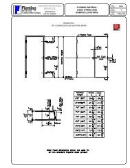
220 Typical Sidelight Frame Ordering Information ........................................ 180<br />
Table 1 Galvanneal <strong>Steel</strong> Thickness and Weights ................................................ 4<br />
Table 2 Galvanneal and Galvanized Coatings ...................................................... 4<br />
Table 3 Wall Anchors for Masonry Partitions ....................................................... 29<br />
Table 4 Wall Anchors for <strong>Steel</strong> Stud Partitions .................................................... 34<br />
Table 5 Rough Opening Sizes in Wood Stud Partitions ....................................... 36<br />
Table 6 Wall Anchors for Wood Stud Partitions ................................................... 39<br />
Table 7 Fire Ratings – Walls, <strong><strong>Door</strong>s</strong> and <strong>Frames</strong> ................................................ 72<br />
Table 8 Maximum Rabbet Opening Sizes for Fire Rated Frame Product ............ 73<br />
Table 9 Maximum Over-All Unit Size for Fire Rated Frame Product .................... 74<br />
Table 10 Maximum Transom opening Sizes for Fire Rated Frame Product .......... 74<br />
Table 11 Maximum Glazed Openings for Fire Rated Sidelights and Windows ...... 74<br />
Table 12 <strong>Fleming</strong> <strong>Door</strong> Series-Gage Classifications ............................................ 126<br />
Table 13 Building-Opening Type Classifications ................................................... 127<br />
Table 14 SDI-100 versus <strong>Fleming</strong> <strong><strong>Door</strong>s</strong> .............................................................. 128<br />
Table 15 <strong>Fleming</strong> Fire <strong>Door</strong> Summary .................................................................. 129<br />
Table 16 Glazing Materials for Fire <strong><strong>Door</strong>s</strong> ............................................................ 130<br />
Page<br />
viii<br />
Date<br />
Mar ‘05
PRINTED IN CANADA<br />
GALVANNEAL STEEL<br />
STEEL DOOR FRAMES<br />
All hollow metal doors and frames manufactured in North America are produced from the<br />
identical base cold rolled steel, which conforms to ASTM A1008.<br />
The galvanneal process begins in the Hot Strip Mill where a billet is reduced in thickness to<br />
a coil of steel.<br />
Figure 1 : Hot Strip Mill Process<br />
The hot rolled steel, meeting ASTM A1011, is then moved to a Cold Strip Mill where it is<br />
uncoiled, pickled, cleaned and rinsed. The steel is heated, passed through dimensioning<br />
rolls to reduce it to the exact thickness required, the edges are trimmed for tension leveling<br />
and the product is oiled to prevent rusting of the now Cold Rolled <strong>Steel</strong>, meeting ASTM<br />
A1008. It is then recoiled or slit into sheets.<br />
It is how the cold-rolled steel is further processed that creates galvanized and paintable<br />
galvanneal.<br />
Figure 2 : Cold Strip Mill Process<br />
Page<br />
1<br />
Date<br />
Mar ‘05
PRINTED IN CANADA<br />
STEEL DOOR FRAMES<br />
For galvanneal and galvanized steel, the cold-rolled coil is processed through a<br />
Galvanizing Mill. It is uncoiled, degreased and run into a continuous hot-dip zinc coating<br />
bath. For galvanized steel the free zinc is removed by a series of mechanical wipers. For<br />
galvanneal, the excess molten zinc is removed using air knives. The galvanneal coil enters<br />
an annealing furnace and heat converts the zinc coating to a zinc-iron alloy. Next the<br />
galvanneal goes through a passivation wash to retard storage stain. Finally both<br />
galvanized and galvanneal steels are recoiled or slit into sheet stock.<br />
DECOILER<br />
ASTM A1008<br />
Cold Rolled <strong>Steel</strong><br />
DEGREASER<br />
CLEANER<br />
ANNEALING<br />
FURNACE<br />
HOT DIP ZINC BATH<br />
(Zinc, Nickle, Chromium &<br />
Copper)<br />
COOLING TOWER<br />
PASSIVATION TANK<br />
Figure 3 : Galvanizing Mill Process<br />
OILER<br />
(Shut Off)<br />
OILER<br />
(Shut Off)<br />
RECOILER<br />
ASTM A924/A653<br />
Galvanneal <strong>Steel</strong><br />
To<br />
<strong>Steel</strong> Service Center<br />
A relative comparison of the coatings and protection provided by them can be easily see in<br />
Figure 4, below.<br />
ASTM STANDARDS FOR STEEL<br />
Figure 4 : CRS vs Galvanneal vs Galvanized <strong>Steel</strong><br />
The process of steel making is a highly sophisticated one, relying on leading edge<br />
technology and is covered by a multitude of ASTM Standards. ASTM Standards for steel<br />
have evolved drastically over the past few years. The changes reflect the availability of<br />
steels with improved base metal characteristics, as well as terminology revisions that are<br />
intended to provide a better understanding of steel sheet formability for hot-dip products.<br />
Page<br />
2<br />
Date<br />
Mar ‘05
PRINTED IN CANADA<br />
STEEL DOOR FRAMES<br />
In the late eighties hot-dip steel products were covered by the following ASTM Standards :<br />
ASTM A366 for the base cold-rolled steel, ASTM A525 for the general requirements of zinc<br />
coated hot-dip steels and ASTM A526 through A528 for the specific forming qualities of<br />
zinc coated steels.<br />
In 1994 A525, together with a number of associated standards, were withdrawn and<br />
replaced by A924-94 which covers all hot-dip coated steels. At the same time A526<br />
through A528 were discontinued and amalgamated under A653.<br />
In 1996 and 1997 ASTM made further changes to A653 where the description of steels with<br />
the "Quality" designations have been made obsolete and a new system of designations<br />
has been developed. Future uses of the "Quality" term are intended for reference to levels<br />
of surface and shape parameters.<br />
ASTM A653-97 designations are for the "Type" of steel, with categories ranging from<br />
Commercial <strong>Steel</strong> (CS) through to High Strength Low Alloy <strong>Steel</strong> (HSLAS). Several<br />
"Types" have further designations, the letters "A", "B", and "C".<br />
The ASTM Standards currently applicable to all <strong>Fleming</strong> paintable Galvanneal are as<br />
follows :<br />
ASTM A1008-03 : Specification for <strong>Steel</strong> Sheet, Cold-Rolled, Carbon, Structural,<br />
High Strength Low-Alloy and High Strength Low-Alloy with<br />
Improved Formability.<br />
This standard describes the general chemical and mechanical properties of cold-rolled<br />
steel.<br />
ASTM A924-99 : Specification for General Requirements for Sheet <strong>Steel</strong>, Metallic-<br />
Coated by the Hot-Dip Process<br />
This standard describes the permitted tolerances for chemical composition, mechanical<br />
properties, coating thickness, widths, lengths, camber, square and flatness of sheet steels<br />
which are metallic-coated by a hot-dip process. The metallic coatings referenced in this<br />
standard include zinc, zinc-iron alloy, aluminum, aluminum-zinc alloy, and lead-tin alloy<br />
(terne).<br />
ASTM A653-03 : Specification for Sheet <strong>Steel</strong>, Zinc-Coated (Galvanized) or Zinc-<br />
Iron Alloy-Coated (Galvannealed) by the Hot-Dip Process<br />
ASTM A653 specifically covers zinc and zinc-iron alloy coated steel. Zinc coated steel,<br />
known as "galvanized", is a full spangled finish product. Zinc-iron alloy coated or<br />
"galvannealed" steel is a spangle-free, matte-gray, uniform finish. This standard describes<br />
six (6) types of steel based on formability. A653 details the nominal and minimum weight of<br />
each type of coating by recognized designations. Galvanized steel coating designations<br />
Page<br />
3<br />
Date<br />
Mar ‘05
PRINTED IN CANADA<br />
STEEL DOOR FRAMES<br />
are prefixed with "G" and galvanneal coating designations are prefixed with "A". Chemical<br />
and mechanical property requirements for both the base steel and the coating are also<br />
included in this standard.<br />
SPECIFICATIONS<br />
The material specifications for <strong>Fleming</strong> Commercial <strong>Steel</strong> <strong>Door</strong> and Frame product is :<br />
<strong>Door</strong> and frame product shall be manufactured from tension leveled steel to ASTM A924-99,<br />
galvanized to ASTM A653-03, Commercial <strong>Steel</strong> (CS), Type B, coating designation A40, known<br />
commercially as paintable galvanneal.<br />
PROPERTIES<br />
Coating<br />
Designation<br />
Gage Nominal Thickness Nominal Weight (lbs/ft 2 )<br />
22 0.030” 1.225<br />
20 0.036” 1.470<br />
18 0.048” 1.960<br />
16 0.060” 2.450<br />
14 0.075” 3.063<br />
12 0.105” 4.288<br />
10 0.138” 5.636<br />
Table 1 : Galvanneal <strong>Steel</strong> Thickness and Weights<br />
Coating Weight (Total Both Sides)<br />
Minimum Check Limit (oz/ft 2 )<br />
Coating Thickness Per Side<br />
Triple Spot Test Single Spot Test µm (microns) Mils<br />
A40 .40 .3 8.9 .36<br />
G90 .90 .8 20 .8<br />
Table 2 : Galvanized and Galvanneal Coatings<br />
Chemical Analysis : Carbon = 0.15% max, Manganese = 0.60% max,<br />
Phosphorus = 0.035% max and Sulphur = 0.040% max<br />
Mechanical Properties : Yield Strength = 43ksi, Ultimate Tensile Strength = 53ksi,<br />
Percentage Elongation in 2” = 36%<br />
Page<br />
4<br />
Date<br />
Mar ‘05
PRINTED IN CANADA<br />
GALVANNEAL ADVANTAGES<br />
STEEL DOOR FRAMES<br />
When specifying materials for hollow metal doors and frames what are the characteristics<br />
you are looking for?<br />
• A smooth, consistent paint surface<br />
• A minimum of surface preparation in the field<br />
• Maximum paint adhesion<br />
• Complete corrosion protection, inside and out<br />
• Maximum compatibility with and flexibility in the selection of finish paints<br />
• Resilience to job site exposure from humidity and water<br />
• Maximum product performance and warranty<br />
Galvanneal has been developed to specifically address these characteristics. In addition,<br />
galvanneal will not fracture when formed and provides maximum arc, spot and projection<br />
weld performance when compared to cold rolled or electro-galvanized steels.<br />
Galvanneal is passivated with a phosphate wash. It presents a dull gray matte surface<br />
which is almost mirror smooth the touch. The surface however, provides microscopic<br />
keying for finish paint at the zinc-iron alloy surface.<br />
Primed painted cold rolled steel on the other hand yields one of two extremes.<br />
Cementisious type factory applied proprietary primers are inherently uneven and rough.<br />
Baked-on electrostatically or conventional spray applied, flow-coat or dip types provide a<br />
glazed egg shell affect which must be fully sanded before finish painting. Flow-coat or dip<br />
process systems can result in uneven coverage, runs and drips.<br />
Galvanneal’s zinc-iron alloy is an integral part of the steel surface. It is on the front, the<br />
back and the edges of the material. <strong>Fleming</strong> manufactures all door and frame components<br />
and reinforcings from galvanneal steel. There are no unprotected surfaces.<br />
With cold rolled product, the factory primers are added after the product is completely<br />
assembled. The consistency and coverage will vary. The inside of frame profiles generally<br />
do not receive the same coverage as the surfaces which will be exposed after installation.<br />
There will be areas on the mortised hardware reinforcings which will receive limited, if any<br />
primer protection. The inside faces of a cold rolled steel door or mullion and the cold rolled<br />
steel internal components and reinforcings receive no primer.<br />
All steel doors and frames need to be cleaned prior to finish painting to remove the dirt,<br />
dust, tar and other foreign matter which end up on the products during shipping, handling<br />
and installation. Scratches in the surface need to be remedied before painting as well.<br />
For galvanneal doors and frames, cleaning is a simple matter of wiping down the surface to<br />
be painted with a cleaner compatible with the finish paint. If latex or alkyd paints are<br />
specified, then detergent and clean water will do the job. For some of the more exotic<br />
Page<br />
5<br />
Date<br />
Mar ‘05
PRINTED IN CANADA<br />
STEEL DOOR FRAMES<br />
finishes such a epoxies and the like, the paint manufacturer will recommend appropriate<br />
materials. The zinc-iron coating will not wash off.<br />
With cold rolled and primed steel there can problems with cleaners removing the primer or<br />
the primer absorbing and trapping foreign materials.<br />
Scratches inflicted on galvanneal doors and frames are repaired with the application of any<br />
off the shelf, zinc-rich galvanized primer, either brush or spray applied after the surface has<br />
been cleaned. You are applying the same material as is already part of the steel surface.<br />
There is never a compatibility problem. The steel surface will not appear different in the<br />
primed areas after finish painting.<br />
With cold-rolled and primed product, the scratches must be sanded out, feathered and a<br />
touch-up primer, compatible with the factory proprietary primer, is applied.<br />
There can be compatibility problems between the proprietary factory primers and standard<br />
commercial primers used by the finish painters. Adhesion of standard commercial primers,<br />
used by the finish painter, may be compromised between his primer and the factory’s.<br />
Paint adhesion and corrosion resistance can be measured using several methods. The<br />
most widely specified test standard for steel door and frame products is ANSI A250.10 .<br />
This standard requires that separate sets of prepared samples are subjected to salt spray<br />
and water fog exposures together with a series of unexposed sample tests.<br />
This standard, although useful, does not provide a thorough evaluation. The salt spray<br />
exposed samples are only evaluated for corrosion resistance (rust). The water fog<br />
exposed samples only for paint blistering. The unexposed samples are evaluated only for<br />
tape test paint adhesion after impacting and lattice style scribing of the painted surface.<br />
The exposures do not address severe acid rain, industrial environments.<br />
Through a nationally recognized independent lab, extensive testing and evaluations<br />
comparing <strong>Fleming</strong> galvanneal and cold rolled steels, each with or without primers and<br />
finish paints, were done. These tests went well beyond the requirements of the ANSI<br />
A250.10 standard, all the way to simulating the demands of an acid rain, industrial<br />
environment. For each type of exposure the samples were evaluated to ASTM standards<br />
for rust, film adhesion, paint blistering and paint creepage.<br />
The results consistently confirm galvanneal’s superior performance prior to and after the<br />
application of finish paint under all tested conditions.<br />
In the last section of the manual you will find our publication “Effective Rust Protection”. It<br />
provides more answers to many of the myths and realities on paintable galvanneal steel.<br />
These are the reasons that <strong>Fleming</strong> paintable galvanneal comes with a 10 year rust<br />
perforation and paint adhesion warranty.<br />
Page<br />
6<br />
Date<br />
Mar ‘05
PRINTED IN CANADA<br />
FRAME PRODUCT DEFINITIONS<br />
STEEL DOOR FRAMES<br />
Frame products fall into 4 categories: frames, transom frames, sidelight frames and<br />
windows.<br />
<strong>Frames</strong> are defined as units that contain single or multiple door openings without horizontal<br />
transom members. <strong>Frames</strong> may be 3 or 4 sided. They may contain flush or rabbetted<br />
panels immediately above the doors. They are available in set-up and welded, knockeddown<br />
or knocked-down slip-on drywall construction. Typical frame elevations are shown in<br />
Figure 5.<br />
Figure 5 : Typical Frame Elevations<br />
Transom <strong>Frames</strong> are units that contain single or multiple door openings with single or<br />
multiple openings above, separated from the doors with a horizontal mullion. The openings<br />
above the doors are called ‘transoms’. The transoms may be filled with glazing materials,<br />
panels or louvers. Transom frames are generally available only in set-up and welded<br />
construction. Typical transom frame elevations are shown in Figure 6.<br />
Figure 6 : Typical Transom Frame Elevations<br />
Sidelight <strong>Frames</strong> contain single or multiple door openings with adjacent openings for<br />
glazing materials, panels or louvers, separated with vertical mullions. The openings<br />
adjacent to the doors are called ‘sidelights’. Sidelight frames may also incorporate single or<br />
multiple transom openings. They are available only in set-up and welded construction.<br />
Typical sidelight frames are shown in Figure 7.<br />
Figure 7 : Typical Sidelight Frame Elevations<br />
Page<br />
7<br />
Date<br />
Mar ‘05
PRINTED IN CANADA<br />
STEEL DOOR FRAMES<br />
Windows are frame product which contain single or multiple openings for glazing materials<br />
only. They do not have any provision for mounting doors. A window which contains only<br />
one opening is also called a ‘borrowed light’ or ‘view window’. Borrowed lights are<br />
available in set-up and welded, knocked-down or knocked-down drywall construction. All<br />
other configurations are available only as set-up and welded. Figure 8 illustrates some<br />
typical elevations of borrowed lights and window assemblies.<br />
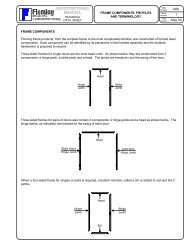
FRAME COMPONENTS<br />
Figure 8 : Typical Borrowed Light and Window Elevations<br />
<strong>Fleming</strong> frame products, from the simplest frame to the most complicated window, are<br />
constructed of formed steel components. Each component can be identified by its<br />
placement in the finished assembly and the builders’ hardware it is prepared to receive.<br />
Three-sided frames for single doors are the most basic units. As shown in Figure 9, they<br />
are constructed from 3 components: a hinge jamb, a strike jamb and a head. The jambs<br />
are handed to suit the swing of the door.<br />
Hinge Jamb<br />
Head<br />
Figure 9 : Single Frame Components<br />
Strike Jamb<br />
Page<br />
8<br />
Date<br />
Mar ‘05
PRINTED IN CANADA<br />
STEEL DOOR FRAMES<br />
Three-sided frames for pairs of doors also contain 3 components: 2 hinge jambs and a<br />
head as shown in Figure 10. The hinge jambs, as indicated, are handed for the swing of<br />
each door.<br />
Right Hand<br />
Hinge Jamb<br />
Head<br />
Figure 10 : Frame Components for Pairs<br />
When a four-sided frame for singles or pairs is required, a bottom member, called a sill, is<br />
added to connect the 2 jambs. Figure 11 illustrates this condition.<br />
Head<br />
Hinge Jamb Strike Jamb<br />
Sill<br />
Figure 11 : 4 Sided Frame Components<br />
Left Hand<br />
Hinge Jamb<br />
All the components in frames for simple singles or pairs are constructed with “open<br />
sections”. An open section is one that contains a throat opening into which a wall can be<br />
inserted. These occur at the perimeter of the frame.<br />
Page<br />
9<br />
Date<br />
Mar ‘05
PRINTED IN CANADA<br />
STEEL DOOR FRAMES<br />
Transom, sidelight and window frames are built with open sections (jambs, head and sills)<br />
at the perimeter and “closed sections”, creating the individual door and/or glass openings<br />
required.<br />
There are a number of closed sections available which include mullions, center rails and<br />
corner posts. Figure 12 shows the general profile details for each of these components.<br />
Mullion Center Rail Corner Post<br />
Figure 12 : Closed Sections<br />
Figure 13 shows various open and closed sections assembled into a finished sidelight<br />
frame.<br />
Blank Jamb<br />
(Open Section)<br />
Blank Mullion<br />
(Closed Section)<br />
Hinge Mullion<br />
(Closed Section)<br />
Head<br />
(Open Section)<br />
Transom Mullion<br />
(Closed Section)<br />
Figure 13 : Typical Sidelight Frame Components<br />
Strike Mullion<br />
(Closed Section)<br />
Center Rail<br />
(Closed Section)<br />
Sill<br />
(Open Section)<br />
Page<br />
10<br />
Date<br />
Mar ‘05
PRINTED IN CANADA<br />
FRAME PROFILES<br />
STEEL DOOR FRAMES<br />
On the previous pages we covered the 4 categories of frame product and the terminology<br />
used to describe each of the components needed to build them.<br />
The components also have a set of terms to describe their basic shape or profile.<br />
PROFILE TYPES<br />
Masonry Profile components are the most common open sections. Illustrated in Figure<br />
10, as the term suggests, they are utilized mostly in unit masonry or concrete walls. The<br />
contractor generally requires them as soon as the foundations are complete as they are<br />
installed with the wall.<br />
Masonry profile frames are available as set-up and welded or knocked-down (for field<br />
assembly) construction. They can also be used in drywall or plaster and stud partitions and<br />
should be available to the contractor before the walls are constructed. Masonry profiles can<br />
include a number of variations as discussed below.<br />
Figure 14 : Double Rabbet Masonry Profile<br />
Double Rabbet masonry profiles are standard for <strong>Fleming</strong> F, Miter and Notch and Stick-<br />
Series welded or knocked-down product. They are designed to accommodate a door or<br />
glazing materials on either side of the profile. Double rabbet profiles are available in both<br />
open sections (Figure 14) and closed sections as illustrated in Figure 15.<br />
Figure 15 : Double Rabbet Mullion<br />
Page<br />
11<br />
Date<br />
Mar ‘05
PRINTED IN CANADA<br />
STEEL DOOR FRAMES<br />
Single Rabbet profiles are the first variation in custom product and have provision for a<br />
door or glazing materials on one side of the frame only. Figure 16 shows an open section<br />
profile and a typical single rabbet mullion.<br />
Open Section Mullion<br />
Figure 16 : Single Rabbet Profiles<br />
Drywall Profile open sections, shown in Figure 17, can be used when drywall is the final<br />
layer of material on the wall. This is the second most common profile in commercial steel<br />
frame product. This profile adds legs, called “drywall returns”, formed parallel to the wall<br />
inside the profile which protect the drywall.<br />
Drywall profile frames are available as set-up and welded or knocked-down slip-on drywall<br />
construction. Welded drywall profile frames should be on site to be installed with the walls.<br />
Knocked-down slip-on drywall frames are installed after the steel or wood studs and drywall<br />
partitions are finished. Double rabbet knocked-down slip-on drywall frames, the DW-Series,<br />
are also a standard profile for <strong>Fleming</strong>.<br />
Double Rabbet Single Rabbet<br />
Figure 17 : Drywall Profiles<br />
Page<br />
12<br />
Date<br />
Mar ‘05
PRINTED IN CANADA<br />
STEEL DOOR FRAMES<br />
Cased Open profiles are another custom variation shown in Figure 18. This profile is<br />
generally used simply as a finishing element over an opening in a wall. Cased open frames<br />
are not normally prepared for doors. With certain types of hinges or pivots these sections<br />
can be used as double acting frames. Cased open knocked-down slip-on drywall profile is<br />
standard for <strong>Fleming</strong>’s CODW-Series.<br />
Masonry Profile Drywall Profile<br />
Figure 18 : Cased Open Sections<br />
Double Egress profiles are used in frames designed to permit each leaf in a pair to swing<br />
in the opposite direction. A plan view of the frame and typical double egress masonry and<br />
drywall profile jambs are shown in Figure 19. The application of this frame design will be<br />
discussed later in greater detail.<br />
Frame Plan View Masonry Profile Jamb Drywall Profile Jamb<br />
Figure 19 : Double Egress<br />
Page<br />
13<br />
Date<br />
Mar ‘05
PRINTED IN CANADA<br />
STEEL DOOR FRAMES<br />
Mullions and center rails also come in standard and optional profiles. Figure 20 illustrates<br />
a standard double rabbet mullion and a custom single rabbet mullion. For center rails, both<br />
single and double rabbet profiles are available. Double rabbet is a standard for <strong>Fleming</strong>’s<br />
Miter and Notch and Stick Series product.<br />
PROFILE TERMINOLOGY<br />
Double Rabbet Single Rabbet<br />
Figure 20 : Mullion Profiles<br />
Over the years terminology has evolved to describe each of the formed elements of open<br />
and closed sections. Industry has adopted a number of different terms. The most widely<br />
accepted and those used by <strong>Fleming</strong>, are shown on the following pages.<br />
Jamb Depth : The distance on a frame section measured from face to face,<br />
perpendicular to the face of the door.<br />
<strong>Fleming</strong> masonry profile frame components are available in standard<br />
jamb depths of 4-3/4”, 5-3/4”, 6-3/4”, 7-3/4” and 8-3/4”. Knockeddown<br />
drywall frame standards include 4-1/2”, 4-3/4”, 5-5/8”, 5-7/8”,<br />
6-1/4”, 6-5/8”, 7-1/8”, 7-3/4”, 8-1/4” and 9-1/2” jamb depths to suit<br />
most steel or wood stud and drywall installations. Non-standard jamb<br />
depths are available to suit special conditions.<br />
Figure 21 : Jamb Depth<br />
Page<br />
14<br />
Date<br />
Mar ‘05
PRINTED IN CANADA<br />
STEEL DOOR FRAMES<br />
Face : The portion of the exposed frame section which runs parallel to the<br />
wall on the door side of the section.<br />
The industry and <strong>Fleming</strong>’s standard is 2” for jambs, heads and<br />
mullions. Masonry profile heads are also available standard with a 4”<br />
face. For center rails 6”, 8” and 12” are the standards. Sill standard<br />
sizes include 6-13/16”, 8” and 8-13/16” faces. <strong>Fleming</strong> Trimwall<br />
Series jamb and mullion sections have 5/8” faces.<br />
Typical non-standard face widths include 1-1/4”, 1-1/2” and 1-3/4”.<br />
Figure 22 : Face<br />
Opposite Face : The portion of the exposed frame section which runs parallel to the<br />
wall on the non-door side.<br />
On standard masonry and drywall, double rabbet profile components<br />
the opposite face matches the face on the door side. To meet specific<br />
architectural requirements, non-standard profiles can be provided<br />
where the faces are not equal.<br />
Figure 23 : Opposite Face<br />
Page<br />
15<br />
Date<br />
Mar ‘05
PRINTED IN CANADA<br />
STEEL DOOR FRAMES<br />
Return : The portion of an open frame section extending back from the faces,<br />
perpendicular to the wall surface.<br />
Except for 5-3/4” jamb depth masonry profile product, the standard<br />
return dimension is 1/2”. The 5-3/4” product has 7/16” returns which<br />
creates a 4-7/8” throat opening to wrap walls constructed with a single<br />
layer of 5/8” drywall on each side of 2” x 4” wood studs or 3-1/2” steel<br />
studs. These are two of the most common walls in commercial<br />
construction.<br />
Non-standard returns from 1/4” to 3/4” on either side are available.<br />
Figure 24 : Returns<br />
Drywall Return : The portion of an open section formed inside the profile, parallel to the wall.<br />
In set-up and welded frames the drywall is secured to the studs after<br />
the frame has been installed. The drywall returns allow the boards to<br />
be slid into position without tearing or marring the board.<br />
For knocked-down slip-on drywall frames the drywall is attached to the<br />
studs before the frame is installed. The drywall returns in this application<br />
permit the frame to be pushed over the partition without damaging the<br />
board.<br />
<strong>Fleming</strong>’s standard drywall return measures 3/8”. Non-standard<br />
drywall returns from 1/4” to 3/4” are available.<br />
Figure 25 : Drywall Returns<br />
Page<br />
16<br />
Date<br />
Mar ‘05
PRINTED IN CANADA<br />
STEEL DOOR FRAMES<br />
Throat Opening : The area in the back of an open section which wraps a wall.<br />
The size of the throat opening is dependent on the actual wall<br />
thickness, the type of frame and installation method required.<br />
For masonry, concrete or drywall partitions where a welded or<br />
knocked down frame wraps the wall, the throat opening should be 1/8”<br />
larger than the actual wall thickness. The gap between the frame and<br />
the partition is sealed with caulking materials.<br />
Where drywall partitions and knocked-down slip on frames are<br />
specified, the throat opening should be equal to the actual wall<br />
thickness.<br />
Figure 26 : Throat Opening<br />
<strong>Door</strong> Rabbet : The portion of the frame section in which the hinge or strike are<br />
mortised or where glazing materials or panels are located.<br />
There are two standard door rabbet sizes. For 1-3/4” thick doors the<br />
door rabbet is 1-15/16” or 1-9/16” for 1-3/8” doors. On double egress<br />
profiles, 1-3/4” thick doors require a door rabbet of 2”.<br />
t<br />
Figure 27 : <strong>Door</strong> Rabbet<br />
Page<br />
17<br />
Date<br />
Mar ‘05
PRINTED IN CANADA<br />
STEEL DOOR FRAMES<br />
Opposite Rabbet : In a double rabbet section, the recess in the profile which is not<br />
prepared for hardware, glazing materials or panels.<br />
For <strong>Fleming</strong> product the opposite rabbet in frames for 1-3/4” thick<br />
doors is 1-9/16”. Where 1-3/8” thick doors are required, the <strong>Fleming</strong><br />
opposite rabbet is 1-15/16”. These are called “unequal rabbet”<br />
profiles.<br />
A communicating frame (a double rabbet frame prepared to receive a<br />
door in each rabbet) with doors of the same thickness is called an<br />
“equal rabbet” frame.<br />
Figure 28 : Opposite Rabbet<br />
Soffit : The portion of the section which connects the stops on a double<br />
rabbet profile or connects the stop and the opposite face on a single<br />
rabbet section.<br />
For <strong>Fleming</strong> standard product, door and opposite rabbets are fixed<br />
dimensions and the soffit size varies with jamb depth.<br />
Figure 29 : Soffit<br />
Page<br />
18<br />
Date<br />
Mar ‘05
PRINTED IN CANADA<br />
STEEL DOOR FRAMES<br />
Stop : The portion of the section which connects the door or opposite rabbet<br />
to the soffit. On the door side of the profile, the part against which the<br />
door closes. Also called the “Stop Height”.<br />
The standard stop for <strong>Fleming</strong> commercial product is 5/8”.<br />
Figure 30 : Stop<br />
Reveal : The portion of a double egress hinge jamb profile which connects the door<br />
rabbet to the door reveal. For <strong>Fleming</strong> product this dimension is 5/8”.<br />
Figure 31 : Reveal<br />
Page<br />
19<br />
Date<br />
Mar ‘05
PRINTED IN CANADA<br />
STEEL DOOR FRAMES<br />
Reveal Rabbet : The portion of a double egress hinge jamb profile which connects the<br />
reveal to the face. Because double egress doors are centered on the<br />
jamb depth, the reveal rabbet and the soffit are equal in size.<br />
Figure 32 : Reveal Rabbet<br />
Backset : The distance in the door rabbet from a cutout, for a hardware<br />
preparation, to the stop. For <strong>Fleming</strong>, 4-1/2” hinges and ASA (4-7/8” x<br />
1-1/4” lipped) strikes have a standard backset of 3/8”.<br />
Figure 33 : Backset<br />
Gage : A numeric designation used to define the nominal thickness of steel.<br />
<strong>Fleming</strong> standard F, Miter and Notch, Stick, KD-DW and A-Series<br />
frames are manufactured from 16 gage galvanneal steel. Nonstandard<br />
frames are available in 12, 14, 16 and 18 gage galvanneal.<br />
The lower the number, the thicker the steel.<br />
Figure 34 : Gage<br />
Page<br />
20<br />
Date<br />
Mar ‘05
PRINTED IN CANADA<br />
STEEL DOOR FRAMES<br />
The illustrations in Figures 35 bring together the terms from the previous pages with<br />
various standard and non-standard profiles.<br />
Double Rabbet Open Section Double Rabbet Mullion<br />
Single Rabbet Open Section Single Rabbet Mullion<br />
Double Egress Jambs Double Egress Heads<br />
Figure 35 : Profile Terminology Summary<br />
Page<br />
21<br />
Date<br />
Mar ‘05
PRINTED IN CANADA<br />
FRAME ASSEMBLY METHODS<br />
STEEL DOOR FRAMES<br />
There are 3 basic methods of assembling frame product : knocked-down, knocked-down<br />
slip-on drywall or set-up and welded.<br />
Knocked-Down (abbreviated as KD) jambs and heads are provided to the contractor<br />
unassembled. The contractor assembles the components together, stands the completed<br />
frame in position, anchors it to the floor and builds the adjacent partition around it.<br />
Knocked-down frames are suitable for new unit masonry, drywall or plaster partitions in<br />
either wrap-around or butted applications. They can also be used in existing partitions.<br />
Knocked-down frames are masonry profile components and are generally used only for<br />
simple 3 or 4 sided frames.<br />
As shown in Figure 36 below, <strong>Fleming</strong> knocked-down jambs are machine mitered at the top<br />
and provided with a 2 corner clip / 4 tab system for alignment and assembly with the head.<br />
Heads are also machine mitered with 4 slots at each end. Once the frame components<br />
have been assembled, the jamb corner clip tabs protruding through the head slots are bent<br />
over to hold the frame together. The jamb/head corner presents a hairline miter joint.<br />
Knocked-down frames can easily be converted to set-up and welded product.<br />
<strong>Fleming</strong> F-Series frames are knocked-down units.<br />
Head<br />
Corner Clip<br />
Hinge Jamb<br />
Figure 36 : F-Series Knocked-Down <strong>Frames</strong><br />
Assembled<br />
Jamb/Head<br />
Intersection<br />
Page<br />
22<br />
Date<br />
Mar ‘05
PRINTED IN CANADA<br />
STEEL DOOR FRAMES<br />
Knocked-Down Slip-On Drywall, (abbreviated as KD-DW) units are also provided to the<br />
contractor unassembled. This type of frame is installed after the rough stud opening is<br />
constructed and the drywall is applied. The contractor “slips” the individual components<br />
over the finished wall.<br />
These units are always drywall profile components. <strong>Fleming</strong> DW-Series units, as shown in<br />
Figure 37, have machine mitered jambs and heads. Jambs are provided with 2 corner<br />
clips, 3 tabs, a compression anchor at the top and each face is punched and dimpled at the<br />
bottom for securing with drywall screws. Heads are provided with 3 slots at each end.<br />
Once the frame components are assembled in the opening, the tabs on each jamb corner<br />
clip are bend over to align and hold the head in place. The frame is squared and secured<br />
at the top with the jamb compression anchors and the base secured with drywall screws<br />
through the faces into the floor runners. The jamb/head corner presents a hairline miter<br />
joint.<br />
Knocked-down slip-on drywall frames are used for 3 and 4-sided frames and borrowed<br />
lights only.<br />
<strong>Fleming</strong> A-Series are also considered knocked-down slip-on frames because of their<br />
installation method. A-Series jambs use a 4-tab corner clip system, have the jamb and<br />
head faces dimpled for screw fixing to the partition but do not have compression anchors.<br />
Head<br />
Compression<br />
Anchor<br />
Corner Clip<br />
Hinge Jamb<br />
Figure 37 : DW-Series Knocked-Down Slip-On Drywall <strong>Frames</strong><br />
Assembled<br />
Jamb/Head<br />
Intersection<br />
Page<br />
23<br />
Date<br />
Mar ‘05
PRINTED IN CANADA<br />
STEEL DOOR FRAMES<br />
Set-Up and Welded frames (abbreviated as SUW) are assembled at the factory or the<br />
distributor’s shop. The contractor places the assembled frame in position, anchors it to the<br />
floor and constructs the required partition around it.<br />
They can be used in new unit masonry or drywall partitions in either wrap-around or butted<br />
applications. For existing walls, set-up and welded frames are used in a butted application<br />
only.<br />
Set-up and welded frames can be masonry or drywall profile.<br />
Knocked-down components can be converted to a set-up and welded frame. As shown in<br />
Figure 38, the top portion of the jamb corner clips are removed and the jambs and head are<br />
assembled in the usual manner. The remaining jamb rabbet clip tabs, inserted through the<br />
head slots, are bent over. The intersecting face miter joints are continuously welded on the<br />
inside of the profile.<br />
When transom, sidelight or window frames are required, this is the assembly method<br />
employed. Intersecting face miters and sill butt face joints are continuously welded on the<br />
inside of the profile, where as mullion and center rail faces are butted and continuously<br />
welded on the outside and ground smooth.<br />
All exposed face miters and butted face joints are body filled, ground to a smooth, uniform<br />
finish and touched up with a zinc-rich primer.<br />
<strong>Fleming</strong> F, A, Miter and Notch and Stick Series product can be assembled using the set-up<br />
and welded method.<br />
Welded Inside Face<br />
Seamless Exposed<br />
Face Miter<br />
Figure 34 : Set-Up and Welded <strong>Frames</strong><br />
Figure 38 : Set-Up and Welded <strong>Frames</strong><br />
Page<br />
24<br />
Date<br />
Mar ‘05
PRINTED IN CANADA<br />
WALLS AND ANCHORS<br />
STEEL DOOR FRAMES<br />
As discussed earlier, certain frame profiles and assembly methods are intended for specific<br />
types of walls and they can be installed in several different ways. In this section we will<br />
cover basic wall construction, frame recommendations and anchoring methods.<br />
Figure 39 below shows a stripped down plan view of a small commercial building that uses<br />
the 3 basic types of wall : unit masonry, drywall partitions and poured concrete. It also<br />
shows combinations of brick and block and brick, block and drywall together.<br />
The architect will use specific types of line work and/or symbols to indicate which type of<br />
wall is required in each location. Figure 39 is fairly typical for most architectural firms<br />
today. It is important that you determine the type of wall so that you can provide the<br />
appropriate frame and anchorage needed.<br />
Poured<br />
Concrete<br />
Unit Masonry<br />
(Block)<br />
Brick & Block<br />
Brick, Block<br />
& Drywall<br />
Figure 39 : Typical Floor Plan<br />
Drywall<br />
Partitions<br />
Page<br />
25<br />
Date<br />
Mar ‘05
PRINTED IN CANADA<br />
STEEL DOOR FRAMES<br />
The illustrations below detail the most common types of wall construction. We have<br />
provided both isometric and plan views of each. The plan views are generally what shows<br />
up on the large scale architectural details.<br />
Figure 40 : Typical Wall Details<br />
Masonry Concrete Block<br />
Poured Concrete<br />
Channel Type <strong>Steel</strong> Stud and Drywall<br />
Wood Stud and Drywall<br />
Page<br />
26<br />
Date<br />
Mar ‘05
PRINTED IN CANADA<br />
MASONRY CONSTRUCTION<br />
STEEL DOOR FRAMES<br />
Brick or block are manufactured in various standard sizes, the most common of which are<br />
4”, 6”, 8”, 10” and 12” nominal thickness. Blocks are actually 3/8” thinner than their nominal<br />
size (ie : 3-5/8”, 5-5/8”, 7-5/8”, 9-5/8” or 11-5/8”).<br />
There are two masonry installation methods: wrap around or butted applications.<br />
Wrap Around application is where the masonry wall is placed inside the throat opening.<br />
The throat opening should be 1/8” greater than the actual wall thickness. The remaining<br />
gap between the wall and the frame is sealed with caulking materials. Figure 41 illustrates<br />
typical wrap around applications and the standard F, Miter and Notch and Stick-Series<br />
jamb depths used with each. The wrap around application is not generally used for 10” or<br />
12” block.<br />
8 5"<br />
3<br />
4" Block<br />
7<br />
5"<br />
8<br />
4 4 3"<br />
8" Block<br />
5 8 5"<br />
6" Block<br />
8<br />
3"<br />
4<br />
Figure 41 : Wrap Around Masonry Applications<br />
6 3"<br />
4<br />
Page<br />
27<br />
Date<br />
Mar ‘05
PRINTED IN CANADA<br />
STEEL DOOR FRAMES<br />
Butted application is the other installation method for masonry walls. In this situation the<br />
jamb depth of the frame is equal to or less than the actual wall thickness. Figure 42 shows<br />
typical butted applications and the different standard F, Miter and Notch and Stick-Series<br />
jambs depths which can be used with each. The butted application is not generally used<br />
for 4” block.<br />
3"<br />
4, 5 4<br />
3"<br />
4,<br />
5<br />
5"<br />
8<br />
4<br />
4<br />
3"<br />
6" Block<br />
9<br />
5"<br />
8<br />
6 3"<br />
4,<br />
10" Block<br />
7<br />
3"<br />
4<br />
8 3"<br />
or<br />
4<br />
4 3"<br />
4,<br />
4 3"<br />
4,<br />
Figure 42 : Butted Masonry Application<br />
7<br />
5"<br />
8<br />
4 3"<br />
5 or 6<br />
3"<br />
4<br />
8" Block<br />
11<br />
5"<br />
8<br />
5<br />
3"<br />
4,<br />
6<br />
3" 3"<br />
4, 4<br />
8 7 or 4 3"<br />
12" Block<br />
Wrap around and butt application masonry frames, whether knocked-down or set-up and<br />
welded, are stood in place, anchored to the floor and the wall is constructed around them.<br />
As the block work progresses up each jamb, wall anchors, positioned above or below the<br />
hinge reinforcings and directly opposite on the strike jamb, are embedded in the mortar<br />
joints between the block courses. The space inside the frame is filled with mortar, which is<br />
referred to as a “fully grouted frame”. The gap between the frame and the wall is sealed<br />
with caulking materials.<br />
Page<br />
28<br />
Date<br />
Mar ‘05
PRINTED IN CANADA<br />
MASONRY WALL ANCHORS<br />
STEEL DOOR FRAMES<br />
Two types of anchors are used to secure frame product in new unit masonry walls : wire or<br />
bridge and strap fire anchors.<br />
These anchors are embedded into the horizontal mortar joints between courses, as the wall<br />
is built-up around the frame.<br />
The number of anchors per jamb is dependent on the frame height not the anchor type.<br />
Industry and <strong>Fleming</strong> standards are as shown in Table 3, below.<br />
Maximum Frame Quantity of<br />
Rabbet Height Anchors per Jamb<br />
5’0” (60”) 2<br />
7’6” (90”) 3<br />
10’0” (120”) 4<br />
12’0” (144”) 5<br />
Table 3 : Anchors in Masonry Partitions<br />
Wire anchors, shown in Figure 43, are the most versatile and commonly used. These<br />
anchors are manufactured from malleable steel, drawn into a loop. The open ends can be<br />
bent to suit any jamb depth. Wire anchors are shipped loose to the job site and installed by<br />
the contractor.<br />
Wire anchors can be used in all non-rated fire door frame product, frames up to 96” x 96”<br />
with up to 1-1/2 hour fire ratings and 3/4 hour fire rated sidelight and window assemblies up<br />
to 96” width or 98” height.<br />
Butted Application<br />
Wrap Application<br />
Brick & Block<br />
Wrap Application<br />
Figure 43 : Masonry Wire Anchor<br />
Page<br />
29<br />
Date<br />
Mar ‘05
PRINTED IN CANADA<br />
STEEL DOOR FRAMES<br />
Bridge and strap fire anchors are used exclusively in fire rated frame product. This type<br />
of anchor is used only for fire rated : 3 hour frames, frames over 96” x 96”, transom frames<br />
or sidelight or window units exceeding 96” width or 98” height.<br />
As shown in Figure 44, the bridge of the anchor is welded inside the soffit of the jamb either<br />
at the factory or the listed distributor’s shop. The strap slides up and down the bridge to<br />
allow for placement within the horizontal mortar joints.<br />
This type of anchor can be used with all jamb depths and profiles of frame product.<br />
Butted Application Wrap Application<br />
Figure 44 : Bridge and Strap Masonry Fire Anchor<br />
Strap<br />
Bridge<br />
Page<br />
30<br />
Date<br />
Mar ‘05
PRINTED IN CANADA<br />
DRYWALL CONSTRUCTION<br />
STEEL DOOR FRAMES<br />
With these types of walls, single or multiple layers of drywall, gypsum, sheet rock or plaster<br />
and lath are affixed to wood or steel studs. Drywall, gypsum and sheet rock are basically<br />
the same thing, a board of gypsum, plaster or cement composition faced with paper,<br />
available in 1/2” or 5/8” thickness.<br />
Plaster and lath are not used very often but can be applied from 3/8” to 1/2” thickness.<br />
STEEL STUD WALLS<br />
There are 3 basic designs of steel stud : truss, nailable and channel. By far the most<br />
common is the channel type. Channel studs are available in 6 different sizes : 1-5/8”,<br />
2-1/2”, 3-1/2”, 3-5/8”, 4” and 6”. With steel studs, the nominal size is the actual size. Not<br />
all sizes are available in all areas of the country.<br />
<strong>Frames</strong> in drywall, in most situations, are installed in a wrap around application. When<br />
welded or knocked-down frames are used, the throat opening should be 1/8” larger than<br />
the wall. For knocked-down slip-on drywall frames the throat should be same as the wall<br />
thickness.<br />
Double steel studs should be used at all jambs and back-to-back runners at all heads.<br />
Figure 45 shows the recommended practice at head and jamb stud intersections.<br />
Upper head runner<br />
notched, bent up<br />
and screw fixed to<br />
inner stud<br />
Upper and lower<br />
head runners<br />
Screw fixed<br />
together<br />
Figure 45 : Recommended Installation<br />
<strong>Steel</strong> Studs at Jamb/Head Intersection<br />
Page<br />
31<br />
Date<br />
Mar ‘05
PRINTED IN CANADA<br />
STEEL DOOR FRAMES<br />
Typical steel stud and drywall partitions, together with the standard jamb depths used with<br />
each, are shown in Figure 46.<br />
3-1/2” <strong>Steel</strong> Stud<br />
+ 5/8” Drywall Each Side<br />
3-5/8” <strong>Steel</strong> Stud<br />
+ 2 Layers of 1/2”<br />
Drywall Each Side<br />
2-1/2” <strong>Steel</strong> Stud<br />
+ 1/2” Drywall Each Side<br />
6” <strong>Steel</strong> Stud<br />
+ 5/8” Drywall Each Side<br />
3-5/8” <strong>Steel</strong> Stud<br />
+ 1/2” Drywall Each Side<br />
3-5/8” <strong>Steel</strong> Stud<br />
+ 2 Layers of 5/8”<br />
Drywall Each Side<br />
2-1/2” <strong>Steel</strong> Stud<br />
+ 5/8” Drywall Each Side<br />
6” <strong>Steel</strong> Stud<br />
+ 2 Layers of 5/8”<br />
Drywall Each Side<br />
Figure 46 : Typical <strong>Steel</strong> Stud and Drywall Partitions<br />
3-5/8” <strong>Steel</strong> Stud<br />
+ 5/8” Drywall Each Side<br />
4” <strong>Steel</strong> Stud<br />
+ 5/8” Drywall Each Side<br />
Page<br />
32<br />
Date<br />
Mar ‘05
PRINTED IN CANADA<br />
STEEL STUD WALL ANCHORS<br />
STEEL DOOR FRAMES<br />
Four types of anchors are used to secure frame product in steel stud and drywall partitions:<br />
combination stud anchors, ‘Z’ anchors, compression anchors and face dimpled anchors.<br />
The selection of anchor type is dependent upon the frame assembly method and the profile<br />
of the jambs.<br />
Combination stud anchors (CSA) are used for standard profile, welded or knocked-down<br />
F, Miter and Notch or Stick-Series frame product where the wall is constructed after the<br />
frame is in place.<br />
The 2 piece CSA, in Figure 47, is available in 2 sizes. One is suitable for all standard<br />
drywall profiles from 4-1/2” to 6-5/8” jamb depth, plus 4-3/4” and 5-3/4” F, Miter and Notch<br />
or Stick-Series masonry profiles. The other size covers standard drywall profile jamb<br />
depths from 7-1/8” to 9-1/2” plus 6-3/4” and 7-3/4” masonry profiles. This anchor is made<br />
of 2 identical size parts which interlock to form the completed anchors. They can easily be<br />
put together to form various sizes to fit multiple standard jamb depths.<br />
The one-piece CSA, also illustrated in Figure 47, is used only in standard masonry profile<br />
frames. It is available in sizes to suit F, Miter and Notch or Stick-Series 4-3/4”, 5-3/4”,<br />
6-3/4”, 7-3/4” and 8-3/4” jamb depths.<br />
2-Piece Combination<br />
Stud Anchor<br />
1-Piece Combination<br />
Stud Anchor<br />
Figure 47 : Combination Stud Anchors<br />
CSA Installation<br />
Both the 1 and 2-piece designs are manufactured from 20 gage galvanneal steel and are<br />
friction fitted inside the profile before the studs are erected.<br />
For all non-fire rated frame product or frames up to 1-1/2 hour rating, either anchor design<br />
may be shipped loose to the site for installation by the contractor.<br />
For 3 hour rated frames and all rated transom, sidelight and window frames, these anchors<br />
must be tack welded into the jambs at the factory or the listed distributor’s shop.<br />
Page<br />
33<br />
Date<br />
Mar ‘05
PRINTED IN CANADA<br />
STEEL DOOR FRAMES<br />
Both designs of CSA are secured through the inner most steel stud with 2 standard 1/2”<br />
long pan head sheet metal screws per anchor. Figure 47 provides a typical completed<br />
installation detail.<br />
‘Z’ anchors, the second type of steel stud anchor, are used for non-standard jamb depth<br />
double rabbet profiles in welded or knocked-down frames. Shown in Figure 48, they are<br />
available in widths of 2”, 3”, 5” and 7” to suit jamb depths up to 9-3/4” and are<br />
manufactured from 16 gage galvanneal steel.<br />
These anchors are tack welded in two places to the inside of the profile at the factory or<br />
distributor’s shop directly above or below the hinge reinforcings and directly opposite on<br />
strike jambs. As with the CSA designs, ‘Z’ anchors are secured through the inner most<br />
stud with 2 standard 1/2” long pan head sheet metal screws per anchor.<br />
Figure 48 : ‘Z’ Anchor<br />
Like masonry wall anchors, the number of anchors per jamb, when using CSA or ‘Z’<br />
anchors is based on the height of the frame. Table 4 below details the requirements.<br />
Maximum Frame Quantity of CSA or<br />
Rabbet Height ‘Z’ Anchors per Jamb<br />
5’0” (60”) 2<br />
7’6” (90”) 3<br />
10’0” (120”) 4<br />
12’0” (144”) 5<br />
Table 4: Anchors in <strong>Steel</strong> Stud Partitions<br />
Typical Installation<br />
Page<br />
34<br />
Date<br />
Mar ‘05
PRINTED IN CANADA<br />
STEEL DOOR FRAMES<br />
Compression anchors are the third type used in steel stud partitions. They are provided<br />
as part of an anchoring system in <strong>Fleming</strong> DW-Series knocked-down slip-on drywall frames<br />
only, where the frame is installed after the wall is completed.<br />
These anchors are factory welded into the upper portion of each jamb. By turning an<br />
adjusting screw located in the jamb soffit, the internal portion of the anchors press snugly<br />
against the steel studs, plumbing and squaring the frame in the opening. Figure 49<br />
illustrates the 18 gage galvanneal compression anchor assembly.<br />
Adjusting<br />
Screw<br />
Faced dimpled anchors is the remaining type for steel stud partitions. The method is<br />
used only on <strong>Fleming</strong>’s A-Series adjustable frames.<br />
The faces of A-Series jambs and heads are factory punched and dimpled for # 8 drywall<br />
screws. After the frame is in place, plumbed and squared, it is anchored to the partition<br />
with 2-1/2” drywall screws. Jambs up to 86” rabbet height receive 3 dimples per face and<br />
jambs up to 96” have 4. Head faces are dimpled at each end, with pairs having an<br />
additional set at the center of the rabbet width. Figure 50 illustrates typical corner<br />
intersection and installation details.<br />
Face<br />
Dimples<br />
Figure 49 : DW-Series Compression Anchor Assembly<br />
Figure 50 : A-Series Frame<br />
Face Dimpled Anchors<br />
Typical Installation<br />
Typical Installation<br />
Page<br />
35<br />
Date<br />
Mar ‘05
PRINTED IN CANADA<br />
WOOD STUD WALLS<br />
STEEL DOOR FRAMES<br />
Wood studs are nominally 2” x 3”, 2” x 4”, 2” x 6” or 2” x 8”. Unlike steel studs, they are<br />
actually 1/2” smaller than their nominal size (ie : a 2” x 4” is really measures 1-1/2” x<br />
3-1/2”).<br />
<strong>Frames</strong> in wood stud and drywall partitions are installed in a wrap around application. As in<br />
most wrap applications, with welded or knocked-down frames, the throat opening should be<br />
1/8” larger than the actual wall thickness. Knocked-down slip-on drywall frames, <strong>Fleming</strong>’s<br />
DW-Series, should be sized so that the throat opening is the same as the actual wall<br />
thickness.<br />
Wood stud partitions are built prior to the installation of the frame in a method called ‘tilt-up<br />
construction’. The wall, complete with rough openings for frames, is built flat on the floor<br />
and then stood or tilted-up into position. Double studs should be used at all jambs with<br />
solid blocking at either side of a framed opening. Figure 51 shows a typical wood stud<br />
partition framed for a single door opening.<br />
Figure 51 : Typical Wood Stud Framed Opening<br />
Table 5 below provides the minimum rough stud opening sizes for <strong>Fleming</strong> F, Miter and<br />
Notch, Stick, DW and A-Series frame product.<br />
Rough Stud<br />
Opening Width<br />
Rough Stud<br />
Opening Height<br />
F, M&N or Stick-<br />
Series <strong>Frames</strong><br />
Over-All Frame<br />
Width + 1/2”<br />
Over-All Frame<br />
Height + 1/4”<br />
Double<br />
Studs<br />
Solid<br />
Blocking<br />
DW-Series<br />
<strong>Frames</strong><br />
Frame Rabbet<br />
Width + 1-7/8”<br />
Frame Rabbet<br />
Height + 3/4”<br />
Table 5 : Rough Stud Opening Sizes<br />
A-Series<br />
<strong>Frames</strong><br />
Frame Rabbet<br />
Width + 1-5/8”<br />
Frame Rabbet<br />
Height + 13/16”<br />
Page<br />
36<br />
Date<br />
Mar ‘05
PRINTED IN CANADA<br />
STEEL DOOR FRAMES<br />
Typical wood stud and drywall partitions, together with the standard jamb depths used with<br />
each, are shown in Figure 52.<br />
2” x 3” Wood Stud<br />
+ 2 Layers of 1/2” Drywall<br />
Each Side<br />
2” x 3” Wood Stud<br />
+ 5/8” Drywall Each Side<br />
2” x 6” Wood Stud<br />
+ 5/8” Drywall Each Side<br />
2” x 3” Wood Stud<br />
+ 1/2” Drywall Each Side<br />
2” x 4” Wood Stud<br />
+ 5/8” Drywall Each Side<br />
2” x 8” Wood Stud<br />
+ 1/2” Drywall Each Side<br />
Figure 52 : Typical Wood Stud and Drywall Partitions<br />
Page<br />
37<br />
Date<br />
Mar ‘05
PRINTED IN CANADA<br />
WOOD STUD WALL ANCHORS<br />
STEEL DOOR FRAMES<br />
Four types of anchors are also used to secure frame product in wood stud and drywall<br />
partitions. Three of them are also used with steel studs : combination stud anchors,<br />
compression anchors and face dimpled anchors. The fourth, wood stud anchors, are used<br />
only in wood stud partitions. Again, as with steel stud construction, the selection of the<br />
appropriate wood stud anchor is dependent on the frame assembly method and profile of<br />
the jambs.<br />
Combination stud anchors (CSA), previously described on Page 33, are used for<br />
standard profile, welded or knocked-down F, Miter and Notch or Stick-Series frame product<br />
where the drywall is applied after the frame is in place.<br />
When used in wood stud partitions, the ‘legs’ on the CSA are bent away from the throat<br />
opening, parallel to the wall and the anchor is secured to the faces of the adjacent jamb<br />
studs with 4 nails per anchor. Figure 53 illustrates these anchors and provides a typical<br />
installation detail.<br />
2-Piece Combination<br />
Stud Anchor<br />
1-Piece Combination<br />
Stud Anchor<br />
Figure 53 : Combination Stud Anchors in Wood Stud Walls<br />
CSA Installation<br />
Wood Stud Wall<br />
Wood stud anchors (WSA) are used specifically in 2” x 4” partitions with welded or<br />
knocked-down F, Miter and Notch or Stick-Series frames where the drywall is installed after<br />
the frame. These 20 gage galvanneal steel anchors are tack welded inside the jamb profile<br />
at the factory or the distributor’s shop directly above or below the hinge reinforcings and<br />
directly opposite on strike jambs.<br />
Wood stud anchors can be used on all non-fire rated and all fire rated frame product. They<br />
are secured to the face of the stud wall with 4 nails per anchor as shown in Figure 54.<br />
Page<br />
38<br />
Date<br />
Mar ‘05
PRINTED IN CANADA<br />
STEEL DOOR FRAMES<br />
Wood Stud Anchor WSA Installation<br />
Figure 54 : Wood Stud Anchors<br />
The number of anchors recommended for CSA and WSA in wood stud and drywall<br />
partitions is shown in Table 6, below.<br />
Maximum Frame Quantity of CSA or<br />
Rabbet Height WSA per Jamb<br />
5’0” (60”) 2<br />
7’6” (90”) 3<br />
10’0” (120”) 4<br />
12’0” (144”) 5<br />
Table 6 : Anchors in Wood Stud Partitions<br />
Compression and face dimpled anchors were covered on Page 35 and shown in Figures<br />
49 and 50. They are used in the same fashion whether installed in steel or wood stud<br />
partitions. Figure 54 illustrates the installation details of both anchors in wood stud walls.<br />
Compression Anchor Face Dimpled Anchors<br />
Figure 55 : Wood Stud Installations<br />
Page<br />
39<br />
Date<br />
Mar ‘05
PRINTED IN CANADA<br />
EXISTING CONSTRUCTION<br />
STEEL DOOR FRAMES<br />
Existing construction is any wall that has been built prior to the installation of the frame. It<br />
occurs in new buildings or those being renovated where frame product is to be installed<br />
against pre-cast, poured concrete or structural steel.<br />
Existing construction is also found in renovation work where masonry or stud and drywall<br />
partitions are to ‘punched-out’ for new openings or where an old frame is to be replaced<br />
with a new one.<br />
Knocked-down and welded frame product, the F, Miter and Notch and Stick-Series, must<br />
utilize a butted application when installed in existing walls. In this application, the jamb<br />
depth is equal to or less than the actual wall thickness.<br />
Knocked-down slip-on frames, either <strong>Fleming</strong>’s KD-DW or A-Series, are used in a wrap<br />
around application in existing walls and the throat opening should be equal to the wall<br />
thickness.<br />
EXISTING PRE-CAST, CONCRETE OR MASONRY WALLS<br />
Figure 56 illustrates typical pre-cast or poured concrete walls and the standard F, Miter and<br />
Notch or Stick-Series jamb depths used with each.<br />
6” Concrete 8” Concrete 10” or 12” Concrete<br />
Figure 56 : Typical Pre-Cast or Poured Concrete Walls<br />
On Page 28, Figure 42, details of butted frames in 6”, 8”, 10” and 12” masonry were<br />
provided and these apply whether the wall is newly constructed or existing.<br />
Page<br />
40<br />
Date<br />
Mar ‘05
PRINTED IN CANADA<br />
STEEL DOOR FRAMES<br />
EXISTING PRE-CAST, CONCRETE OR MASONRY WALL ANCHORS<br />
As with new partitions, the selection of anchor types in existing walls is governed by the<br />
frame assembly method and profile of the frame.<br />
Existing pre-cast, poured concrete or masonry partitions, with knocked-down or welded<br />
frames, have two styles of existing wall anchor (EWA) available : butterfly or strap and<br />
spacer.<br />
In both cases, the soffit of the jamb is punched and dimpled for 1/4” diameter expansion<br />
shell anchor bolts or Tapcon concrete screws. The anchor preparations are located in the<br />
soffit, 6” from the top and bottom of each jamb, adjacent to the center hinge and directly<br />
opposite on strike or blank jambs. EWA guides are tack-welded inside the jamb profile at<br />
the factory or the distributor’s shop. The frame is placed in the opening, squared and<br />
plumbed. For expansion shell type anchors, holes to suit the expansion shell anchor are<br />
drilled in the partition. The expansion shell anchors are placed into the holes and<br />
tightened, securing the frame in place. For Tapcon concrete screws, after the frame is<br />
squared and plumbed in the openig, pilot holes are drilled and the Tapcons are screwed in<br />
place. Expansion bolt anchors and Tapcons are supplied by the contractor.<br />
Butterfly type existing wall anchor guides, shown in Figure 57, are manufactured from 18<br />
gage galvanneal steel. This style is used in 2” face, double rabbet, masonry profile<br />
sections.<br />
Figure 57 : Butterfly Existing Wall Anchor Guide<br />
Strap and spacer type existing wall anchor guides, illustrated in Figure 58, are 16 gage<br />
galvanneal steel. There are 5 standard strap widths to suit jamb depths from 4-3/8” to<br />
9-5/16”. This style is used in single or double rabbet masonry profiles where the butterfly<br />
type is not suitable.<br />
Figure 58 : Strap and Spacer Existing Wall Anchor Guide<br />
Page<br />
41<br />
Date<br />
Mar ‘05
PRINTED IN CANADA<br />
STEEL DOOR FRAMES<br />
Face dimpled anchors, standard with <strong>Fleming</strong>’s A-Series frame, as detailed in Figure 59,<br />
are the only option when a wrap application in existing pre-cast, concrete or masonry is<br />
needed. The frame is secured with 2-1/2” long 3/16” diameter flat head Tapcon screws in<br />
the jambs and head.<br />
Pre-Cast or Concrete Partitions Masonry Partitions<br />
EXISTING DRYWALL PARTITIONS<br />
Figure 59 : A-Series Frame<br />
Face Dimpled Anchors<br />
In renovation work, openings are sometimes ‘punched-out’ of an existing drywall partition<br />
for a new frame. In this type of work only KD-DW or A-Series, knocked-down slip-on<br />
frames in a wrap application will work.<br />
The installation of either series of frame and its anchorage is identical to new construction<br />
in drywall. Compression and face dimpled anchors in steel stud walls are detailed on Page<br />
35 and for wood stud partitions on Page 39.<br />
Page<br />
42<br />
Date<br />
Mar ‘05
PRINTED IN CANADA<br />
FLOOR ANCHORS<br />
STEEL DOOR FRAMES<br />
As well as being secured to the wall, most frames are fixed to the floor. There are 3 basic<br />
types: floor anchor straps, face-dimpled drywall base anchors and mullion floor anchors.<br />
Floor anchor straps are available in 3 designs : one for standard double rabbet and cased<br />
open profiles, another for non-standard single rabbet sections and the third for double<br />
egress hinge jambs. As shown in Figure 60, each type is welded to the inside of the frame<br />
profile and is ram set or bolted to the floor through the 2 holes provided.<br />
These 16 gage galvanneal steel anchors are used in welded or knocked-down frames<br />
installed in new masonry or stud and drywall partitions.<br />
Standard Single Rabbet Double Egress<br />
Figure 60 : Floor Anchor Straps<br />
Welded or knocked-down frames in existing pre-cast, concrete or masonry frames cannot<br />
be anchored to the floor. The EWA preparations and guide located 6” from the bottom of<br />
each jamb act as the floor anchor.<br />
Page<br />
43<br />
Date<br />
Mar ‘05
PRINTED IN CANADA<br />
STEEL DOOR FRAMES<br />
Face-dimpled base anchors are used in knock-down drywall KD-DW Series frames.<br />
Each jamb face is punched and dimpled 3/4” from the bottom for standard # 8 drywall<br />
screws which secure the base of the frame to the steel floor runner or wood sill plate.<br />
Face dimpled<br />
base anchor<br />
Figure 61 : KD-DW Series<br />
Face Dimpled Base Anchor<br />
A similar base anchor is used in <strong>Fleming</strong> A-Series frames. As illustrated in Figure 62, each<br />
jamb face is punched and dimpled 4” from the bottom and screws secure the base of the<br />
frame to the partition.<br />
Face dimpled<br />
base anchor<br />
Figure 62 : A-Series<br />
Face Dimpled Base Anchor<br />
Page<br />
44<br />
Date<br />
Mar ‘05
PRINTED IN CANADA<br />
STEEL DOOR FRAMES<br />
Mullion floor anchors are used to secure mullions which terminate at the floor. These<br />
anchors are manufactured from 12 gage galvanneal steel and are provided with 2 holes<br />
through which they are ram set or bolted to the floor.<br />
There are 5 standard sizes to suit 4-3/4”, 5-3/4”, 6-3/4”, 7-3/4” and 8-3/4” standard jamb<br />
depth, 2” face mullions. Non-standard sizes are also available.<br />
As shown in Figure 63, the mullion is placed over the installed anchor and holes are drilled<br />
through the mullion face and the anchor. The mullion is then secured to the anchor with<br />
# 12 x 1/2” long pan head sheet metal screws.<br />
Non-fire rated mullions receive 1 screw per face. Mullions in fire rated frames require 2 per<br />
face.<br />
Non-Rated Fire Rated<br />
Figure 63 : Mullion Floor Anchors<br />
Page<br />
45<br />
Date<br />
Mar ‘05
PRINTED IN CANADA<br />
HARDWARE<br />
LOCATIONS<br />
STEEL DOOR FRAMES<br />
All <strong>Fleming</strong> frame products utilize standard locations for hinge and strike jamb preparations.<br />
Hinge jambs for frames 6’8” through 7’2” height are prepared for three 4-1/2” standard<br />
weight (.134” leaf thickness) hinges with a 3/8” backset. All strike jambs are prepared for<br />
an ASA (1-1/4” x 4-7/8”) strike with a 3/8” backset and 3 silencers.<br />
Figure 64 illustrates the standard hardware locations for <strong>Fleming</strong> frame product, 6’8” to 7’2”<br />
rabbet height.<br />
Figure 64 : Standard Hardware Locations<br />
Page<br />
46<br />
Date<br />
Mar ‘05
PRINTED IN CANADA<br />
REINFORCINGS<br />
STEEL DOOR FRAMES<br />
<strong>Fleming</strong> frame products utilize common components beyond their floor and wall anchors.<br />
Hinge, strike and closer reinforcings, both standard and optional, are typical through the<br />
product lines.<br />
The following section provides you with basic information on the most common<br />
preparations and reinforcements.<br />
High frequency hinge reinforcings, shown in Figure 65, are provided at all hinge cutouts<br />
as a standard with <strong>Fleming</strong>. This unique 10 gage galvanneal steel angle design is far<br />
superior to traditional 3/16” thick flat bar hinge reinforcings. Each reinforcing is secured in<br />
the section with 6 projection welds. All hinge cutouts (except on A-Series frames) are<br />
protected with 20 gage galvanneal steel mortar guard boxes.<br />
The hinge reinforcings supplied standard are off-set, drilled and tapped for 4-1/2” standard<br />
weight hinges. A standard weight hinge has a leaf thickness of .134” . Each reinforcing bar<br />
is provided with 4 raised 'donuts' which may be ground off by the distributor to convert from<br />
standard weight to heavy weight (.180” thick leaf) hinges.<br />
<strong>Fleming</strong> can also provide reinforcing for non-standard hinge leaf thickness, 5” hinges,<br />
anchor hinges, pivots, continuous and other specialized type hinges.<br />
Figure 65 : High Frequency Hinge Reinforcing<br />
Page<br />
47<br />
Date<br />
Mar ‘05
PRINTED IN CANADA<br />
STEEL DOOR FRAMES<br />
ASA strike reinforcings are provided standard in all <strong>Fleming</strong> strike jambs and mullions.<br />
An ASA strike is 4-7/8” tall, 1-1/4” wide and has a lip 3-3/8” tall which allows the latch bolt to<br />
retract without marring the frame.<br />
In addition, all strike jambs are provided with 3 bumper holes, factory punched in the stop.<br />
One is centered at the strike height, the other two, 10” from the top and bottom of the frame<br />
rabbet opening.<br />
Two designs of reinforcing are utilized : one for open sections, the other for mullions and<br />
A-Series strike jambs. Both designs are secured to the frame with 6 projection welds per<br />
reinforcing.<br />
In Figure 66, the left unit is the design used in open sections. This 16 gage galvanneal<br />
component has an integral mortar guard box sized to take up to 1” long latch or dead bolts.<br />
The strike mounting holes are extruded and tapped to an effective 12 gage material<br />
thickness to ensure a high performance product.<br />
The right side illustrates the 12 gage galvanneal steel strike reinforcing for mullions and<br />
A-Series strike jambs.<br />
Strike Jambs Mullions and A-Series<br />
Strike Jambs<br />
Figure 66 : ASA Strike Reinforcings<br />
Page<br />
48<br />
Date<br />
Mar ‘05
PRINTED IN CANADA<br />
STEEL DOOR FRAMES<br />
SMALL ASA/NL strike reinforcing is an optional preparation on all <strong>Fleming</strong> product.<br />
Shown in Figure 67, they can be used as a stand alone prep or in conjunction with an ASA<br />
strike.<br />
These 14 gage galvanneal steel reinforcings are coined, drilled and tapped to suit standard<br />
2-3/4” x 1-1/8” no lip strikes provided with most cylindrical and mortise deadlocks.<br />
Small ASA/NL strike reinforcings are secured to the inside of the profile with 3 tack welds<br />
each and for all open sections (except A-Series frames) are protected with 22 gage<br />
galvanneal steel mortar guard boxes.<br />
Figure 67 : Small ASA/NL (Deadlock) Strike Reinforcing<br />
Page<br />
49<br />
Date<br />
Mar ‘05
PRINTED IN CANADA<br />
STEEL DOOR FRAMES<br />
Surface strike reinforcing is another option available on all <strong>Fleming</strong> frame product. This<br />
type of strike is used on openings equipped with rim exit devices. Shown in Figure 68, this<br />
12 gage galvanneal steel reinforcing plate is secured to the inside of the strike jamb soffit<br />
with 3 tack welds.<br />
The flat bar reinforcing is 11-7/8” long and from 3/4” to 2” wide in 1/4” increments. The<br />
reinforcing is generally 1/4” narrower than the soffit width and is installed tight against the<br />
door stop.<br />
Figure 68 : Surface Strike Reinforcing<br />
In addition to the 3 presented, <strong>Fleming</strong> can provide frame product prepared for nonstandard<br />
strike sizes or locations and specialized units such as electric strikes.<br />
Page<br />
50<br />
Date<br />
Mar ‘05
PRINTED IN CANADA<br />
STEEL DOOR FRAMES<br />
Surface closer reinforcing in heads is another option available. Abbreviated as CRW, for<br />
closer reinforcing – welded, this option provides the necessary material thickness and<br />
strength required to mount surface closers.<br />
As shown in Figure 69, the standard 12 gage galvanneal steel flat bar reinforcings,<br />
measuring 11-7/8” long and 1-1/2” wide, are secured to the inside of the head or transom<br />
mullion face with 3 tack welds at the factory or distributor’s shop.<br />
Figure 69 : Surface Closer Reinforcing<br />
Page<br />
51<br />
Date<br />
Mar ‘05
PRINTED IN CANADA<br />
STEEL DOOR FRAMES<br />
Parallel arm closer reinforcing is a second type available on all <strong>Fleming</strong> heads and<br />
transom mullions. Abbreviated as P/A, it also uses 12 gage galvanneal steel flat bar<br />
reinforcings 11-7/8” long.<br />
Parallel arm closers are soffit mounted. When the soffit is less than 2” in width an<br />
additional reinforcing is provided in the opposite rabbet. Soffit reinforcings are available<br />
from 3/4” to 1-3/4” widths, in 1/4” increments. Opposite rabbet reinforcings are from 3/4” to<br />
1-1/2” width. When the opposite rabbet reinforcings are required, the total width of the 2<br />
reinforcings is 2-1/4”.<br />
Figure 70 : Parallel Arm Closer Reinforcing<br />
Page<br />
52<br />
Date<br />
Mar ‘05
PRINTED IN CANADA<br />
STEEL DOOR FRAMES<br />
Reversible flush bolt strikes and reinforcings are also available for all <strong>Fleming</strong> frame<br />
product heads and transom mullions. Used in pairs only, this combination head cut-out,<br />
strike reinforcing and flush both strike are illustrated in Figure 71.<br />
The cut-out is made in the door rabbet, centered over the meeting edges of the two doors.<br />
The 16 gage chromated galvanneal steel reinforcing is spot welded into place inside the<br />
head or transom mullion in two places.<br />
The strike itself, also 16 gage chromated galvanneal steel, has a rectangular hole punched<br />
at one end. The strike is screw fixed to the reinforcing with the hole on the left side when<br />
the inactive leaf, the one with the flush bolt, is left hand swing. Reverse the strike and it is<br />
ready for a right hand door.<br />
Figure 71 : Reversible Flush Bolt Strike and Reinforcing<br />
<strong>Fleming</strong> can also provide a number of non-standard head preparations including : mortise<br />
closers and holders, door position switches, surface maglocks and mortise vertical rod<br />
strikes.<br />
Page<br />
53<br />
Date<br />
Mar ‘05
PRINTED IN CANADA<br />
HANDING<br />
STEEL DOOR FRAMES<br />
Frame product is manufactured to suit the handing of the doors hung in them.<br />
Although the terms “hand” and “swing” are used interchangeably, technically “swing”<br />
describes the direction of egress for the frame and “hand” defines the operating direction of<br />
a door.<br />
The hand of every door can be defined using one of the following terms: Left Hand, Right<br />
Hand, Left Hand Reverse or Right Hand Reverse.<br />
Left or Right Hand doors are those where the key for the latching device is located on the<br />
push side (or back) of the door. In other words, when you are locking or unlocking the<br />
door, you will push the door away from you to operate it.<br />
Figure 72 : Right or Left Hand<br />
Reverse Hand doors (also referred to as reverse bevel doors) are those where the key is<br />
located on the pull side (or front) of the door. When you are locking or unlocking the door,<br />
you will pull the door towards you to operate it.<br />
Figure 73 : Reverse Hand or Reverse Beveled<br />
There are 6 types of frame swing configurations with variations of each recognized in<br />
industry. The illustrations on the following pages detail the various door and hardware<br />
handings and frame swings available.<br />
Page<br />
54<br />
Date<br />
Mar ‘05
PRINTED IN CANADA<br />
STEEL DOOR FRAMES<br />
Singles are the simplest type of frame available. Single frames are either left or right-hand<br />
swing. Figure 74 illustrates “single acting” doors, those which operate in one direction only.<br />
A left hand swing frame will use either a left hand or a right hand reverse door. Conversely,<br />
a right hand swing frame uses either right hand or left hand reverse doors.<br />
Figure 74 : Singles (Single Acting)<br />
Page<br />
55<br />
Date<br />
Mar ‘05
PRINTED IN CANADA<br />
STEEL DOOR FRAMES<br />
Pairs are frames with two doors hung in the same rabbet opening without a vertical center<br />
mullion between them. In a pair, one or both doors may contain a latching device. A door<br />
with a latching device is called an “active” leaf. The door in a pair prepared for a strike is<br />
called the “inactive” leaf. Figure 75 details the 6 variations of pairs available based on door<br />
handing.<br />
Figure 75 : Pairs<br />
Double Egress is a specialized type of frame with a pair of doors operating in opposite<br />
directions. The doors in double egress frames are always reverse handed and both leafs<br />
are active.<br />
Figure 76 : Double Egress<br />
Page<br />
56<br />
Date<br />
Mar ‘05
PRINTED IN CANADA<br />
STEEL DOOR FRAMES<br />
R/L, L/L and R/R units are similar to pairs, but have a fixed or removable mullion between<br />
the doors. They are in fact two single doors, each with its own rabbet opening. They can<br />
be reverse handed, but both leafs are active.<br />
Figure 77 : R/L, L/L and R/R<br />
Contra-Swing is similar in function to a double egress unit. The two doors swing in the<br />
opposite direction but latch into a vertical mullion placed between them. Either door can be<br />
reverse handed, but both leafs are active.<br />
Figure 78 : Contra-Swing<br />
Page<br />
57<br />
Date<br />
Mar ‘05
PRINTED IN CANADA<br />
STEEL DOOR FRAMES<br />
Double Acting frames permit doors to operate in both directions, towards or away from<br />
their closed position. They are available in singles or pairs. Double acting frames are<br />
usually fabricated from cased open components.<br />
Figure 79 : Double Acting<br />
Page<br />
58<br />
Date<br />
Mar ‘05
PRINTED IN CANADA<br />
STEEL DOOR FRAMES<br />
Communicating frames are double rabbet units prepared to accept a door in each rabbet.<br />
They typically facilitate access and control between individual hotel or motel rooms.<br />
Figure 80 : Communicating <strong>Frames</strong><br />
Multi-Opening frames, transom and sidelight frames are also available. These units<br />
contain 3 or more doors in combinations of singles, pairs, double egress, contra-swing or<br />
double acting configurations. In Figure 81 a few straight forward units are detailed.<br />
Figure 81 : Multi-Opening Units<br />
Page<br />
59<br />
Date<br />
Mar ‘05
PRINTED IN CANADA<br />
FRAME SERIES<br />
STEEL DOOR FRAMES<br />
Now that you have an understanding of frame profiles, assembly methods, anchoring,<br />
hardware reinforcing, handing and terminology in general terms, the following pages will<br />
cover <strong>Fleming</strong>’s five basic series of frame product.<br />
This section is intended to provide you with a working knowledge and over-view of our<br />
varied standard frame series and how they can apply to the projects you are supplying.<br />
F-SERIES<br />
The F-Series is our standard knocked-down masonry frame product with applications<br />
in block, concrete and drywall partitions.<br />
This series can utilize wire or bridge and strap fire anchors, one or two-piece<br />
combination stud anchors, wood stud anchors or the butterfly existing wall anchor<br />
guides.<br />
The F-Series is eligible for fire ratings up to an including 4’0” x 10’0” singles and 8’0” x<br />
10’0” pairs at 3 hours.<br />
The standard features of this series are :<br />
• 16 gage punch-mitered, double rabbet, masonry profile, commercial frame for<br />
1-3/4" thick doors<br />
• Jambs, heads and all components fabricated from paintable galvanneal steel<br />
• All components projection welded<br />
• All hinge locations provided with <strong>Fleming</strong> 10 gage high frequency hinge reinforcing<br />
(see Figure 65, Page 47)<br />
• All hinge reinforcings dimpled to convert from standard to heavy weight<br />
• All hinge reinforcings protected with dust boxes<br />
• 16 gage ASA strike reinforcing with 1" deep integral dust box (see Figure 66, Page<br />
48)<br />
• Strike jambs and double heads machine punched for door silencers<br />
• Knocked-down, convertible to set-up and welded construction. Each jamb provided<br />
with 2 projection welded KD corner clips and head machine slotted for corner clip tabs<br />
• Floor anchor projection welded into all jambs (see Figure 60, Page 43)<br />
• 2" face x 5/8" stop profile with unequal rabbets<br />
• Available in standard widths, heights and jamb depths<br />
• All hinge jambs provided with embossed (die stamped) UL fire label<br />
Figure 82 on the next page will provide you with illustrations of typical heads, jambs and<br />
the standard jamb head intersection after assembly along with profile and standard size<br />
information.<br />
Page<br />
60<br />
Date<br />
Mar ‘05
PRINTED IN CANADA<br />
Typical Head<br />
Typical Hinge Jamb<br />
STEEL DOOR FRAMES<br />
Figure 82 : F-Series Standard Profiles and Sizes<br />
Assembled Knocked<br />
Down Corner<br />
Page<br />
61<br />
Date<br />
Mar ‘05
PRINTED IN CANADA<br />
DW-SERIES<br />
STEEL DOOR FRAMES<br />
The DW-Series is a knocked-down drywall profile product installed in steel or wood stud<br />
partitions after the application of the drywall.<br />
DW-Series is eligible for fire ratings up to and including 1-1/2 hours at 3’6” x 7’2” or 3’0” x<br />
8’0” singles and 7’0” x 7’2” pairs.<br />
Standard Features<br />
• 16 or 18 gage punch-mitered, double rabbet, drywall profile, commercial frame for<br />
1-3/4" doors<br />
• 18 gage punch-mitered, double rabbet, drywall profile, commercial frame for 1-3/8" doors<br />
• 16 gage punch-mitered, cased open drywall profile commercial frame<br />
• Jambs, heads and all components fabricated from paintable galvanneal steel<br />
• All components projection welded<br />
• All hinge locations provided with <strong>Fleming</strong> 10 gage high frequency hinge reinforcing<br />
(see Figure 65, Page 47)<br />
• All hinge reinforcings dimpled to convert from standard to heavy weight<br />
• 16 gage ASA strike reinforcing with 1" deep integral dust box (see Figure 66, Page 48)<br />
• Strike jambs and double heads machine punched for door silencers<br />
• Knocked-down (slip-on) construction. Each jamb provided with 2 projection welded<br />
KD corner clips and head machine slotted for corner clip tabs<br />
• Adjustable compression anchor projection welded into top of each jamb (see Figure 49,<br />
Page 35)<br />
• Each jamb face punched and dimpled for drywall screw attachment to floor studs (see<br />
Figure 61, Page 44)<br />
• 2" face x 5/8" stop profile with unequal rabbets.<br />
• Available in standard widths and heights and jamb depths<br />
• All hinge jambs for 1-3/4" doors are provided with an embossed (die stamped) UL fire label<br />
Figure 83, below, details typical jambs, heads and the standard DW-Series knocked-down<br />
drywall corner intersection. Figure 84 on the next page provides the profile and standard<br />
sizes available.<br />
Typical Head Typical Hinge Jamb<br />
Figure 83 : Standard DW-Series Frame Details<br />
Assembled Knocked Down<br />
Drywall Series Corner<br />
Page<br />
62<br />
Date<br />
Mar ‘05
PRINTED IN CANADA<br />
STEEL DOOR FRAMES<br />
Figure 84 : Standard DW-Series Profiles and Sizes<br />
Page<br />
63<br />
Date<br />
Mar ‘05
PRINTED IN CANADA<br />
DE-SERIES (DOUBLE EGRESS) FRAMES<br />
STEEL DOOR FRAMES<br />
Double egress is a set-up and welded, masonry profile frame installed in block, concrete<br />
or drywall partitions.<br />
It contains a pair of doors operating in opposite directions, generally installed in a crosscorridor<br />
situation. Figure 85 shows typical plan views of double egress assemblies, both<br />
right and left hand swinging.<br />
Right Hand Swing Left Hand Swing<br />
Figure 85 : Double Egress Units<br />
These frames can utilize wire or bridge and strap fire anchors, special “Z” stud anchors or<br />
the strap and spacer type existing wall anchor guides.<br />
DE-Series frames are eligible for fire ratings up to 8’0” x 10’0” at 3 hours.<br />
The standard features are :<br />
• 16 gage, masonry profile, commercial frame for 1-3/4" thick doors<br />
• 2" face, double 5/8" stopped jambs, factory notched at top to suit wrap around applications<br />
• 2" face, single rabbet heads factory assembled, exposed stop ends at center completely<br />
finished and heads factory notched at each end for set-up and welded butt joint at jambs<br />
• Welded-in inverted channel provided at the center of each head<br />
• Jambs, heads and all components fabricated from paintable galvanneal steel<br />
• All components projection welded<br />
• All hinge locations provided with <strong>Fleming</strong> 10 gage high frequency hinge reinforcing (see<br />
Figure 65, Page 47)<br />
• All hinge reinforcings dimpled to convert from standard to heavy weight<br />
• All hinge reinforcings protected with dust boxes<br />
• Floor anchor projection welded into all jambs (see Figure 60, Page 43)<br />
• Available in standard widths, heights and jamb depths<br />
• All hinge jambs are provided with an embossed (die stamped) UL fire label<br />
Figure 86, on the next page, illustrates typical hinge jamb, head, set-up and welded corner<br />
details.<br />
Page<br />
64<br />
Date<br />
Mar ‘05
PRINTED IN CANADA<br />
Inverted Channel<br />
Factory notched at each<br />
end to suit jamb butt joint<br />
Typical Factory Assembled Head<br />
Inverted Channel<br />
Typical Section through Head<br />
STEEL DOOR FRAMES<br />
Welded Inside Face<br />
Figure 86 : Standard Double Egress Frame Details<br />
Typical Hinge Jamb<br />
Page<br />
65<br />
Date<br />
Mar ‘05<br />
Factory notched for wrap-<br />
around applications<br />
Typical Assembled Hinge Jamb and Head<br />
Seamless Face<br />
Butt Joint
PRINTED IN CANADA<br />
STEEL DOOR FRAMES<br />
Because the doors in double egress frames are centered on the jamb depth, the door<br />
rabbet is 2” instead of 1-15/16” and the soffit and reveal rabbets on the hinge jambs are<br />
equal. As shown in Figure 87 below, the jambs are ‘double stopped’ and the heads are<br />
single rabbet profiles.<br />
Figure 87 : Standard Double Egress Series Profiles and Sizes<br />
Page<br />
66<br />
Date<br />
Mar ‘05
PRINTED IN CANADA<br />
A-SERIES (ADJUSTABLE) FRAMES<br />
STEEL DOOR FRAMES<br />
The A-Series is our adjustable jamb depth frame product. It is a knocked-down slip-on<br />
drywall profile which can be used in stud and drywall, existing block and concrete<br />
partitions.<br />
This series is available in 3 sizes : 4-1/2”, 5-1/16” and 7-7/8” to suit walls from 3-1/2” to<br />
12-1/2” thickness, designated as "S" (small for 4-1/2"), "M" (medium for 5-1/16") and "L"<br />
(large for 7-7/8").<br />
The hinge and strike jambs and the heads of this series are face dimpled for either # 8<br />
drywall screws or 3/16” diameter Tapcon screws which anchor the frame securely to the<br />
wall.<br />
A-Series frames are eligible for fire ratings up to 4’0” x 8’0” singles, 8’0” x 8’0” pairs, to<br />
1-1/2 hour rating.<br />
The standard features of this frame series are :<br />
• 16 gage punch-mitered, adjustable jamb depth, drywall profile, commercial frame<br />
for 1-3/4" doors<br />
• Jambs, heads and all components fabricated from paintable galvanneal steel<br />
• Standard jamb depths; 4-1/2” (to wrap 3-1/2" through 5-5/8" walls); 5-1/16” (to<br />
wrap 4-1/16" through 6-7/8" walls) and; 7-7/8” (to wrap 6-7/8" through 12-1/2"<br />
walls)<br />
• All components projection welded<br />
• All hinge locations provided with <strong>Fleming</strong> 10 gage high frequency hinge<br />
reinforcing (see Figure 65, Page 47)<br />
• All hinge reinforcings dimpled to convert from standard to heavy weight<br />
• 12 gage ASA strike reinforcing (see Figure 66, Page 48)<br />
• Strike jambs and double heads machine punched for door silencers<br />
• Knocked-down, convertible to set-up and welded construction. Each jamb<br />
provided with 2 projection welded KD corner clips and head machine slotted for<br />
corner clip tabs<br />
• Jamb and head components connected with 2-piece, 14 gage sliding angle<br />
bracket assemblies<br />
• Jambs and heads punched and face dimpled for #8 drywall or 3/16” diameter<br />
Tapcon screw anchors (see Figure 50, Page 35)<br />
• 2" face x 5/8" stop profile<br />
• Available in standard widths and heights<br />
• All hinge jambs are provided with an embossed (die stamped) UL fire label<br />
Figure 88 on the next page, provides you with standard profile and jamb/head intersection<br />
details.<br />
Page<br />
67<br />
Date<br />
Mar ‘05
PRINTED IN CANADA<br />
Typical Head<br />
Typical Hinge Jamb<br />
STEEL DOOR FRAMES<br />
Figure 88 : Standard A-Series Profiles and Sizes<br />
Standard Knocked-Down<br />
Slip-On A-Series<br />
Assembled Corner<br />
Page<br />
68<br />
Date<br />
Mar ‘05
PRINTED IN CANADA<br />
MN-SERIES (MITER AND NOTCH) AND ST-SERIES (STICKS)<br />
STEEL DOOR FRAMES<br />
These two Series are used for multi-opening frames, transom, sidelight and window<br />
assemblies. Both are 16 gage galvanneal steel, masonry profile, distributor assembled<br />
product.<br />
With the MN-Series, jambs, heads, mullions, sills, center rails, corner posts and filler<br />
pieces are ordered from the factory as machine mitered or notched to length components,<br />
to suit the specific requirements of the unit to be built.<br />
ST-Series components are ordered and inventoried by the distributor in standard 10’<br />
length “sticks”. The distributor does the miters, notches and assembles them into the final<br />
unit.<br />
Both MN and ST-Series products are constructed as set-up and welded units for<br />
installation in block, concrete or drywall partitions.<br />
The standard features common to both Series are:<br />
• 16 gage double rabbet, masonry profile, paintable galvanneal steel, commercial frame<br />
components for 1-3/4" doors<br />
• All hardware reinforcings projection welded<br />
• All hinge locations provided with <strong>Fleming</strong> 10 gage high frequency hinge reinforcing<br />
(see Figure 65, Page 47)<br />
• All hinge reinforcings dimpled to convert from standard to heavy weight<br />
• In open hinge sections, reinforcings protected with dust boxes<br />
• In open strike sections, 16 gage ASA strike reinforcing with 1" deep integral dust box<br />
(see Figure 66, Page 48)<br />
• In strike mullions, 12 gage ASA strike reinforcing (see Figure 66, Page 48)<br />
• Floor anchor projection welded into all open section hinge and strike jambs (see Figure<br />
60, Page 43)<br />
• Full compliment of standard hinge/strike prep combinations in open and mullion<br />
sections<br />
• 2” face hinge, strike and blank open sections<br />
• Mullions - 2" face<br />
• Heads and sills – 2”, 4”, 6-13/16", 8", 8-13/16" and 12" face<br />
• Center rails - 6", 8" and 12" face<br />
• Cased open sections - 2" face<br />
• Stopped and cased open filler pieces<br />
• Corner posts - 2 and 3 way<br />
• Available in standard widths, heights and jamb depths<br />
• All hinge sections are provided with an embossed (die stamped) UL fire label<br />
Figure 89, on the next page, provides profile details for the various standard MN and ST-<br />
Series components available.<br />
Page<br />
69<br />
Date<br />
Mar ‘05
PRINTED IN CANADA<br />
Figure 89 : MN and ST-Series Components<br />
STEEL DOOR FRAMES<br />
The illustration below in Figure 90 shows an exploded version of the components for a<br />
typical sidelight frame with the various miters and notches and the finished set-up and<br />
welded assembly.<br />
Figure 90 : MN or ST-Series Components for a Typical Sidelight Frame<br />
Page<br />
70<br />
Date<br />
Mar ‘05
PRINTED IN CANADA<br />
FIRE RATED FRAME PRODUCT<br />
STEEL DOOR FRAMES<br />
<strong>Steel</strong> door and frame assemblies play a crucial role in providing the fire and life safety<br />
protection required in most buildings today. Fire protection requirements are established<br />
by the building code governing the area in which the building is to be erected and the uses<br />
to which the building will be put.<br />
The fire protection of a wall opening requires a complete assembly which includes the door,<br />
frame, glazing materials, builders’ hardware and the installation.<br />
The basic requirements relating to doors and frames are included in this manual. For<br />
information on installation the National Fire Protection Association (NFPA) standard, NFPA<br />
80, “Fire <strong><strong>Door</strong>s</strong> and Windows” should be consulted. This standard is specified as a<br />
governing document in most North American Building Codes.<br />
The manufacturers of builders’ hardware and the <strong>Door</strong> and Hardware Institute publish<br />
documents which cover that facet of the industry.<br />
Another good reference guide is the National Association of Architectural Metal<br />
Manufacturers, Hollow Metal Manufacturers division (NAAMM-HMMA) publication entitled<br />
“Fire-Rated Hollow Metal Fire <strong><strong>Door</strong>s</strong> and <strong>Frames</strong>”, manual number HMMA-850. This<br />
document brings together information from various sources into one booklet.<br />
Our manual, the “Basic Hollow Metal Training Manual”, provides a general over-view only<br />
of our capabilities for fire rated product. <strong>Fleming</strong> publishes a stand-alone, comprehensive<br />
guide to the subject, entitled the “<strong>Fleming</strong> Fire Labeling Specifications” catalogue which has<br />
been included in the last section of the manual. When you need specific, detailed<br />
information on the requirements and limitations which apply to <strong>Fleming</strong> fire labeled<br />
products, you will find this an invaluable source.<br />
Fire doors and frames, since the early 1900’s, have been run to what has evolved into the<br />
UL10b standard, published by Underwriters Laboratories. Other standards, which mirror<br />
the UL one, include NFPA 252. These standards have been historically known as ‘negative<br />
or neutral pressure’ tests. The neutral plane for these has been located at the top of the<br />
frame assembly.<br />
In 1997 the International Conference of Building Officials (ICBO) adopted and published an<br />
alternate test method to be run under ‘positive pressure’, called UBC 7-2 (1997) for the<br />
Uniform Building Code. UL has developed UL10c which addresses all the requirements of<br />
the UBC standard. UL10c and UBC 7-2 (1997) require the neutral plane to be located 40”<br />
from the bottom of the assembly.<br />
Page<br />
71<br />
Date<br />
Mar ‘05
PRINTED IN CANADA<br />
STEEL DOOR FRAMES<br />
Other changes, such as the development of positive pressure standards by NFPA and<br />
ASTM and the International Building Code (IBC), a single model code for the United States,<br />
will evolve and be adopted over the next few years.<br />
From a fire rating stand point, there are three basic levels of performance or endurance,<br />
each tied to the rating of the wall. The basic rule of thumb is : door, frame and hardware<br />
fire protection ratings equal three-quarters of the wall's fire resistance rating. Table 7<br />
outlines the relationship between opening location, wall rating and door and frame rating. It<br />
is the responsibility of the architect to determine and schedule the requirements of all<br />
openings in the building based on the local building code.<br />
Opening Description<br />
Wall Fire<br />
<strong>Door</strong> and Frame<br />
Resistance<br />
Fire Protection Rating<br />
Rating<br />
Openings in walls which separate buildings or<br />
divide a single building into fire areas<br />
Openings in; enclosures of ‘vertical communication’ such as stairwells<br />
4 Hour 3 Hour<br />
and elevator shafts or; exterior walls subject to severe fire exposure<br />
from outside the building<br />
2 Hour 1-1/2 Hour<br />
Openings between occupancies 1 Hour 1 Hour<br />
Openings in; corridors and room partitions or; exterior walls subject to<br />
light to moderate fire exposure from outside the building<br />
1 Hour 3/4 Hour<br />
Openings where smoke control is the primary consideration or;<br />
1/3 Hour<br />
between a habitable room and a corridor when the wall has a fire<br />
resistance rating not more than 1 Hour or; across corridors<br />
1 Hour<br />
(No Hose Stream - US)<br />
(With Hose Stream -<br />
where a smoke partition is required<br />
Canada)<br />
Table 7 : Fire Ratings – Walls, <strong><strong>Door</strong>s</strong> and <strong>Frames</strong><br />
Our products are available with labels from the most recognized certification agencies and<br />
laboratories in North America: Underwriters Laboratories (UL), and Warnock Hersey /<br />
Intertek Testing Services (WHI/ITS).<br />
Fire door and frame product are identified as such only by the presence of a label issued by<br />
the certification angency. Labels are available in a number of materials which include<br />
metal drive riveted, adhesive-backed mylar or for frames, labels embossed (stamped)<br />
directly into the product. Facsimiles of the various labels available from <strong>Fleming</strong> are<br />
provided on Pages 32 and 33 of the Fire Labeling Specification brochure.<br />
Fire labels are applied only at the factory or a ‘listed’ distributor shop. Distributors eligible<br />
to apply fire labels have been approved by the certification agency under an In-Plant<br />
Labeling Program. These programs have been developed to ensure that the distributor has<br />
the facilities and expertise to assemble and / or modify product in accordance with the<br />
requirements of the agency. Approved distributors are subject to on-going, unannounced<br />
inspections by agency personnel to ensure compliance with the program.<br />
The field application of fire labels, except under the direct supervision of lab inspection<br />
services, is strictly forbidden. A separate program, called a Special Field Inspection (SFI),<br />
is available to rectify problems related to the field labeling of <strong>Fleming</strong> fire door and frame<br />
product. Please contact the factory for additional information.<br />
Page<br />
72<br />
Date<br />
Mar ‘05
PRINTED IN CANADA<br />
STEEL DOOR FRAMES<br />
<strong>Fleming</strong> has been testing fire doors and frame product for over 35 years and has some of<br />
the most extensive and comprehensive listings in North America. The Tables below<br />
provide an over-view summary of our capabilities for fire door frame product.<br />
Construction Product Gage<br />
3 Hour 1-1/2 Hour 3/4 Hour<br />
Assy<br />
12<br />
Method Singles Pairs Singles Pairs Singles Pairs<br />
14<br />
16<br />
SUW 4 0 x 10 0 8 0 x 10 0 5 0 x 12 0 10 0 x 12 0 5 0 x 12 0 10 0 x 12 0<br />
14<br />
16<br />
KD 4 0 x 10 0 8 0 x 10 0 4 0 x 10 0 8 0 x 10 0 4 0 x 10 0 8 0 x 10 0<br />
SUW 3 6 x 7 2 6 0 x 7 2 3 6 x 7 2 6 0 x 7 2 3 6 x 7 2 6 0 x 7 2<br />
18<br />
KD 3 0 x 7 2 6 0 x 7 2 3 0 x 7 2 6 0 x 7 2 3 0 x 7 2 6 0 x 7 2<br />
<strong>Frames</strong><br />
16<br />
18<br />
KD-DW - -<br />
3 6 x 7 2<br />
3 0 x 8 0 7 0 x 7 2 3 6 x 7 2<br />
3 0 x 8 0 7 0 x 7 2<br />
Fr – Panel<br />
Above <strong>Door</strong><br />
16<br />
18<br />
SUW - - 4 0 x 8 0 - 4 0 x 8 0 -<br />
Transom<br />
<strong>Frames</strong><br />
12<br />
14<br />
16<br />
SUW 4 0 x 10 0 8 0 x 10 0 5 0 x 12 0 10 0 x 12 0 5 0 x 12 0 10 0 x 12 0<br />
Standard<br />
Sidelight<br />
<strong>Frames</strong><br />
14<br />
16<br />
SUW - - 4 0 x 10 0 8 0 x 10 0 4 0 x 10 0 8 0 x 10 0<br />
<strong>Frames</strong><br />
14<br />
16<br />
SUW<br />
KD<br />
- 8 0 x 10 0 - 8 0 x 10 0 - 8 0 x 10 0<br />
Transom<br />
<strong>Frames</strong><br />
14<br />
16<br />
SUW - - - 8 0 x 10 0 - 8 0 x 10 0<br />
Double<br />
Egress<br />
Sidelight<br />
<strong>Frames</strong><br />
14<br />
16<br />
SUW - - - - - 8 0 x 10 0<br />
<strong>Frames</strong><br />
14<br />
16<br />
SUW<br />
KD<br />
- - 2 x 4 0 x 8 0 - 2 x 4 0 x 8 0 -<br />
Transom<br />
<strong>Frames</strong><br />
14<br />
16<br />
SUW - - 2 x 4 0 x 8 0 - 2 x 4 0 x 8 0 Contra-<br />
Swing<br />
-<br />
Sidelight<br />
<strong>Frames</strong><br />
14<br />
16<br />
SUW - - - - 2 x 4 0 x 8 0 12<br />
-<br />
14 SUW 4<br />
16<br />
0 x 10 0 - 4 0 x 10 0 - 4 0 x 10 0 -<br />
<strong>Frames</strong><br />
14<br />
16<br />
KD 4 0 x 8 0 - 4 0 x 8 0 - 4 0 x 8 0 Dutch<br />
<strong>Door</strong><br />
-<br />
Transom<br />
<strong>Frames</strong><br />
12<br />
14<br />
16<br />
SUW 4 0 x 10 0 - 4 0 x 10 0 - 4 0 x 10 0 -<br />
<strong>Frames</strong><br />
14<br />
16<br />
SUW - - 4 0 x 8 0 8 0 x 8 0 4 0 x 8 0 8 0 x 8 0<br />
Multi-<br />
Opening Transom<br />
<strong>Frames</strong><br />
14<br />
16<br />
SUW - - - - 4 0 x 8 0 8 0 x 8 0<br />
A-Series <strong>Frames</strong><br />
14<br />
16<br />
SUW<br />
KD<br />
- - 4 0 x 8 0 8 0 x 8 0 4 0 x 8 0 8 0 x 8 0<br />
Table 8 : Maximum Rabbet Opening Sizes for Frame Product<br />
Page<br />
73<br />
Date<br />
Mar ‘05
PRINTED IN CANADA<br />
STEEL DOOR FRAMES<br />
Product Partition Type 2 & 3 Hour 1 & 1-1/2 Hour<br />
1/3 (c) , 1/2 &<br />
3/4 Hour<br />
Drywall 10 0 ht 12 0 ht 12 0 Transom<br />
ht<br />
<strong>Frames</strong> (a) Other (b) 10 0 ht 12 0 ht 12 0 ht<br />
Drywall -<br />
96 ft 2 area<br />
10 0 w or 10 0 ht<br />
12 10 w x 11 4 Sidelight<br />
ht<br />
<strong>Frames</strong><br />
Other (b) -<br />
120 ft 2 area<br />
12 0 w or 12 0 ht<br />
13 6 w x 12 0 ht<br />
Drywall -<br />
96 ft 2 area<br />
10 0 w or 10 0 ht<br />
12 10 w x 11 4 Window<br />
ht<br />
Assemblies<br />
Other (b) -<br />
120 ft 2 area<br />
12 0 w or 12 0 ht<br />
13 6 w x 12 0 ht<br />
(a) : Maximum combined door/transom opening height<br />
(b) : “Other” includes masonry, existing masonry, concrete or structural steel<br />
(c) : With or without hose stream test<br />
Table 9 : Maximum Over-All Unit Size for Frame <strong>Products</strong><br />
Another area presently under going major changes is the glazing materials industry. Many<br />
new materials have been introduced over the past few years and are available for use in<br />
fire rated transom, sidelight and window assemblies. Table 10 provides a summary of<br />
maximum individual exposed light sizes available. Please refer to Pages 28 to 31 of the<br />
Fire Labeling Specifications for more detailed information.<br />
Listed<br />
Glazing Material<br />
1/4” Georgian<br />
Wired Glass<br />
Specialized<br />
Wired Glass<br />
Laminated or<br />
Ceramic Glazing (b)<br />
2 & 3 Hour 1 & 1-1/2 Hour<br />
- -<br />
- -<br />
(c) 2<br />
3288 in area<br />
94-5/8" w<br />
94-5/8" ht<br />
3456 in 2 area (a)<br />
96” w x 54” ht<br />
3/8" Thick Cement<br />
Board Panels<br />
1/2" Thick Gypsum<br />
-<br />
Board Panels<br />
1-3/4" Honeycomb or<br />
5760 in<br />
Vertically Stiffened<br />
Panels<br />
2 area<br />
48” w x 120” ht<br />
(a) : Available in Transom <strong>Frames</strong> only<br />
(b) : Maximum sizes for each rating, not the same material for each<br />
(c) : 2 Hour rating maximum<br />
4990 in 2 area<br />
126" w or 126" ht<br />
3456 in 2 area<br />
96” w x 54” ht<br />
-<br />
5760 in 2 area<br />
48” w x 120” ht<br />
1/3, 1/2 & 3/4 Hour<br />
(With Hose Stream<br />
- Canada Only)<br />
1296 in 2 area<br />
54” w or 54” ht<br />
4608 in 2 area<br />
48” w x 96” ht<br />
5605 in 2 area<br />
96” w or 96” ht<br />
3456 in 2 area<br />
96” w x 54” ht<br />
1296 in 2 area<br />
54" w or 54" ht<br />
5760 in 2 area<br />
48” w x 120” ht<br />
1/3 Hour<br />
(No Hose Stream<br />
- US Only)<br />
5268 in 2 area<br />
110-3/8" w<br />
110-3/8" ht<br />
5268 in 2 area<br />
110-3/8" w<br />
110-3/8" ht<br />
6272 in 2 area<br />
106-1/2” w<br />
106-1/2” ht<br />
3456 in 2 area<br />
96” w x 54” ht<br />
1296 in 2 area<br />
54" w or 54" ht<br />
5760 in 2 area<br />
48” w x 120” ht<br />
Table 10 : Maximum Individual Exposed Light Sizes – Transoms, Sidelight and Window <strong>Frames</strong><br />
Page<br />
74<br />
Date<br />
Mar ‘05
PRINTED IN CANADA<br />
INSTALLATION<br />
STEEL DOOR FRAMES<br />
The final area to be covered in this section is that of frame installation. <strong>Fleming</strong>, as you<br />
have seen from the previous pages, manufactures 6 basic series of frame product : F, DE,<br />
MN, ST, DW and A-Series. The F-Series are available as knocked-down or welded<br />
product. DE, MN and ST-Series frames are all set-up and welded. Our DW-Series is a<br />
knocked-down slip-on drywall application. The A-Series is a special knocked-down slip-on<br />
drywall application which can be converted to welded construction.<br />
Installation methods and sequence varies with the construction of the frame and wall type.<br />
F, DE, MN AND ST-SERIES WELDED AND F-SERIES KNOCKED-DOWN FRAMES<br />
Welded and knocked-down frames are set in place with the wall being constructed around<br />
them.<br />
For knocked-down frames start at Step 1, welded frames at Step 2.<br />
1. Assemble Frame<br />
a) Insert jamb corner clip tabs into 4 slots at each end of head<br />
b) Ensure that face miters on jambs and heads are tight and corners are square<br />
c) Bend the tabs at each head rabbet slot downwards away from the door opening and<br />
the tabs at each head return slot downwards towards the throat opening<br />
Figure 91 : KD Corner Assembly<br />
Page<br />
75<br />
Date<br />
Mar ‘05
PRINTED IN CANADA<br />
STEEL DOOR FRAMES<br />
2. Remove Temporary Spreaders<br />
a) Welded frames are provided with temporary steel spreaders to maintain alignment and<br />
minimize other damage during shipping and handling. They are not intended to be<br />
used during the installation and must be removed.<br />
Figure 92 : Temporary Shipping Spreaders<br />
For new unit masonry or steel stud partitions proceed to Step 3.<br />
For wood stud partitions go to Step 7.<br />
For existing unit masonry or poured concrete walls proceed to Step 8.<br />
3. Place and Anchor to Floor<br />
a) Stand frame in position<br />
b) Place a wooden spreader between the jambs at the floor. The spreader must be<br />
square, at least 1” thick, almost as wide as the frame jamb depth with clearance<br />
notches at each end for the frame stops/soffits<br />
Figure 93 : Wooden Spreaders<br />
c) Level the frame head, placing shims under the jamb floor anchors as necessary<br />
d) Adjust frame for alignment and twist. Rabbets must be parallel<br />
e) Fasten jambs to the floor through the floor anchors<br />
Figure 94 : Floor Anchor<br />
Page<br />
76<br />
Date<br />
Mar ‘05
PRINTED IN CANADA<br />
STEEL DOOR FRAMES<br />
4. Set Frame<br />
a) Brace the frame as shown. Do not brace in the direction of the adjacent wall<br />
b) Install a second wooden spreader at the mid-height of the frame to maintain correct<br />
frame rabbet width and to prevent bowing of the jambs<br />
Figure 95 : Braced Frame<br />
5. New Unit Masonry Wall Anchorage<br />
a) As the wall is laid up, embed wire or masonry fire anchors in mortar coursing<br />
immediately above or below each hinge and directly opposite on the strike jambs<br />
b) Although not mandatory, even for fire-rated frames, grouting of the jambs is<br />
recommended in all units to ensure a more secure and stable installation<br />
Figure 96 : Masonry Wire Anchor Installation<br />
Page<br />
77<br />
Date<br />
Mar ‘05
PRINTED IN CANADA<br />
STEEL DOOR FRAMES<br />
6. <strong>Steel</strong> Stud Partition Anchorage<br />
a) Where loose combination stud anchors are provided, install in frame throat opening<br />
directly above or below each hinge reinforcing and immediately opposite on the strike<br />
jamb<br />
b) Remove or bend legs of combination stud anchors back inside the frame profile<br />
Figure 97 : Combination Stud Anchor<br />
c) Place and secure floor and ceiling steel runners<br />
d) Place, plumb and secure the first vertical steel studs inside the floor and ceiling runners<br />
with stud fitting snug against the wall anchors in each jamb. The open webs of the first<br />
studs should be facing away from the frame<br />
e) With standard 1/2” long pan head sheet metal screws, secure studs to each anchor<br />
f) Check plumb and square of frame, alignment and twist of jambs<br />
g) Place and secure a second vertical steel stud inside the floor and ceiling runners with<br />
stud returns abutting the first steel stud returns<br />
h) Install and secure steel lintel runners at the head of the frame<br />
Figure 98 : Securing <strong>Steel</strong> Studs and Anchors<br />
7. Wood Stud Partition Anchorage<br />
Page<br />
78<br />
Date<br />
Mar ‘05
PRINTED IN CANADA<br />
STEEL DOOR FRAMES<br />
Wood stud partitions are constructed prior to the installation of the frame in a method<br />
called ‘tilt-up construction’. The wall, complete with rough openings for frames, is built<br />
flat on the floor and then stood or tilted-up into position. Double studs should be used<br />
at all jambs with solid blocking at both sides of the framed opening.<br />
a) The rough stud opening width should be 1/2” greater than the over-all frame width<br />
b) The rough stud opening height should be 1/4” greater than the over-all frame height<br />
Figure 99 : Wood Rough Stud Opening<br />
c) Install and secure optional adjustable floor anchors to the floor anchor straps with the<br />
floor legs extending into the frame rabbet opening<br />
Figure 100 : Adjustable Floor Anchor<br />
d) Where loose combination stud anchors are provided, install in frame throat opening,<br />
directly above or below each hinge reinforcing and immediately opposite on the strike<br />
jamb, with the anchor legs bent outwards, parallel to the finished wall<br />
Figure 101 : Combination Stud Anchor<br />
Page<br />
79<br />
Date<br />
Mar ‘05
PRINTED IN CANADA<br />
STEEL DOOR FRAMES<br />
e) Set the assembled frame, centered in the rough stud opening width, with the wall<br />
anchors wrapping the faces of the jamb studs<br />
f) Place a wooden spreader between the jambs at the bottom of the frame. See Step 3b<br />
for additional information on the wooden spreaders<br />
g) Level the frame head, placing shims under the floor anchors as necessary<br />
h) Adjust the frame for alignment and twist. Rabbets must be parallel<br />
Figure 102 : Frame in Wood Stud Partition<br />
i) Fasten jamb to floor through the floor anchors<br />
j) Install a second wooden spreader at the mid-height of the frame to maintain correct<br />
rabbet width and to prevent the bowing of the jambs<br />
k) Plumb and square frame<br />
l) Secure frame to studs with 4 nails per anchor<br />
m) Check plumb and square of frame, alignment and twist of jambs<br />
Figure 103 : Anchors for Wood Stud Partitions<br />
Page<br />
80<br />
Date<br />
Mar ‘05
PRINTED IN CANADA<br />
STEEL DOOR FRAMES<br />
8. Existing Masonry or Poured Concrete Wall Anchorage<br />
a) Set the assembled frame centered in the completed opening<br />
b) Place wooden spreaders between the jambs at the floor and at mid-height of the frame<br />
c) Level the head by placing shims under the jambs as necessary<br />
d) Adjust the frame for plumb, square, alignment and twist. Rabbets must be parallel<br />
e) Mark the wall through the dimpled holes in each jamb soffit to locate the anchor points<br />
f) Drill the wall for 1/4” diameter anchor bolts in non-rated frames or 3/8” diameter anchor<br />
bolts for rated product, at the marks<br />
g) Install sleeve or expansion shell anchors in the wall holes<br />
h) Insert anchor bolts through the dimpled holes into the wall sleeve anchors<br />
i) Place shims snugly between the frame and the wall above each anchor bolt<br />
j) Tighten bolts, checking plumb, square, alignment and twist<br />
Figure 104 : Existing Wall Anchors<br />
Page<br />
81<br />
Date<br />
Mar ‘05
PRINTED IN CANADA<br />
DW-SERIES KNOCKED-DOWN SLIP-ON DRYWALL FRAMES<br />
STEEL DOOR FRAMES<br />
These frames, our DW-Series, are installed by slipping the components over the completed<br />
partition.<br />
1. Size Opening<br />
a) Install double steel or wood studs at all jambs. See Figure 105 for recommended<br />
practice at head and jamb stud intersections.<br />
Figure 105 : Head and Jamb Stud Intersection<br />
It is important to ensure that the rough stud openings for double rabbet profiles are<br />
sized as follows:<br />
Rough stud opening width (RSOW) = rabbet width + 1-7/8”<br />
Rough stud opening height (RSOH) = rabbet height + 3/4”<br />
b) For cased open drywall profiles (CODW), RSOW = rabbet width + 2-3/4” and RSOH =<br />
rabbet height + 1-3/8”<br />
c) The tolerances are + 1/4”/ - 0” on RSOW and RSOH for all DW and CODW-Series<br />
frames<br />
2. Install Head<br />
Figure 106 : Rough Stud Openings<br />
Page<br />
82<br />
Date<br />
Mar ‘05
PRINTED IN CANADA<br />
STEEL DOOR FRAMES<br />
a) For fire rated pairs only, install snap-in anchors in each face at the center line of the<br />
head. See Figure 108 for installation of anchors<br />
b) Slide head into position in the center of the rough stud opening. Wedges may be used<br />
to temporarily hold the head in position<br />
Figure 107 : Head Installation<br />
3. Install Hinge Jamb<br />
a) If optional snap-in anchors are to be used to secure the base of the frame to the stud<br />
sill plates / runners, install in each face at the bottom of the jamb. The drywall does not<br />
need to be notched.<br />
Figure 108 : Snap-In Anchor Installation<br />
b) Retract the tension anchor at the top of the jamb by turning the screw clock-wise<br />
Figure 109 : Adjusting Tension Anchor<br />
Page<br />
83<br />
Date<br />
Mar ‘05
PRINTED IN CANADA<br />
STEEL DOOR FRAMES<br />
c) Insert the integral soffit tab on the jamb and tabs on the corner clip into the slots in the<br />
head. Pivot the jamb into place over the wall<br />
Figure 110 : Install Hinge Jamb<br />
4. Install Strike (or 2 nd Hinge) Jamb<br />
a) For fire rated singles only, install a snap-in anchor in each face of the strike jamb<br />
immediately above the strike reinforcing<br />
b) Repeat Steps 3a through 3c<br />
Figure 111 : Install Strike Jamb<br />
Page<br />
84<br />
Date<br />
Mar ‘05
PRINTED IN CANADA<br />
STEEL DOOR FRAMES<br />
5. Anchor Frame<br />
a) Place a temporary wooden spreader between the jambs at the floor to ensure the<br />
correct frame rabbet width at the base of the frame. The spreader must be square, at<br />
least 1” thick, almost as wide as the frame jamb depth with clearance notches at each<br />
end for the stop/soffits.<br />
b) Shim the bottom of the jambs to the same elevation so that the head is level<br />
c) Secure the bottom of the frame through the dimpled holes at the base of each jamb<br />
with standard drywall screws into the sill plate / runner. If the optional snap-in anchors<br />
are used, secure to the sill plate / runner with 2 standard # 8 x 1-1/4” drywall screws<br />
per anchor. Both jambs rabbets must be parallel<br />
Figure 112 : Anchor Frame<br />
6. Set Frame<br />
a) Plumb and square-up the frame by adjusting the tension anchors at the top of each<br />
jamb, ensuring that they press tightly against the studs<br />
Figure 113 : Plumb and Square Frame<br />
Page<br />
85<br />
Date<br />
Mar ‘05
PRINTED IN CANADA<br />
STEEL DOOR FRAMES<br />
b) On fire rated frames, secure the snap-in anchors at the strike jamb or head to studs<br />
with 2 standard drywall screws per anchor<br />
c) Bend over the corner clip tabs at the head slots, over towards the wall<br />
d) Remove the temporary wooden spreader<br />
Figure 114 : Bend Tabs at Head<br />
A-SERIES ADJUSTABLE KNOCKED-DOWN DRYWALL FRAMES<br />
Our A-Series (adjustable jamb depth) frames are designed for wrap applications in existing<br />
partitions. They can be used in unit masonry, concrete and steel or wood stud and drywall<br />
locations. A-Series frames, like our DW-Series, slip over the completed wall.<br />
1. Size Opening<br />
a) It is imperative that the rough opening sizes are as follows:<br />
Rough opening width (ROW) = rabbet width + 1-5/8”<br />
Rough opening height (ROH) = rabbet height + 13/16”<br />
b) The tolerances are + 1/4” / - 0 for both ROW and ROH<br />
Figure 115 : Rough Opening Sizing<br />
Page<br />
86<br />
Date<br />
Mar ‘05
PRINTED IN CANADA<br />
STEEL DOOR FRAMES<br />
2. Set Frame Throat Opening<br />
a) Adjust each jamb and head to suit the measured wall thickness<br />
b) Tighten all adjustable sliding assembly screws. Failure to do so may create installation<br />
and operational problems and will void the warranty<br />
Figure 116 : Adjustable Sliding Assembly<br />
3. Install Head<br />
a) Slide the head into position in the center of the rough opening width. Wedges may be<br />
used to temporarily hold the head in position<br />
Figure 117 : Head Installation<br />
Page<br />
87<br />
Date<br />
Mar ‘05
PRINTED IN CANADA<br />
STEEL DOOR FRAMES<br />
4. Install Hinge Jamb<br />
a) Insert the tabs on the jamb corner clips into the slots in the head<br />
b) Pivot the jamb into place over the wall<br />
Figure 118 : Install Hinge Jamb<br />
c) Jamb corner clip tabs should protrude through the slots in the head rabbets and returns<br />
5. Install Strike (or 2 nd Hinge) Jamb<br />
a) Repeat Steps 4a through 4c<br />
Figure 119 : Corner Clips at Head<br />
Figure 120 : Install Strike Jamb<br />
Page<br />
88<br />
Date<br />
Mar ‘05
PRINTED IN CANADA<br />
STEEL DOOR FRAMES<br />
6. Set Frame<br />
a) Center the head in the rough opening width<br />
b) Bend the corner clip tabs extending through the head returns down towards the throat<br />
opening to tighten the miters<br />
Figure 121 : Securing Miter<br />
c) Place a temporary wooden spreader between the jambs at the floor to ensure the<br />
correct frame rabbet width at the base of the frame. The spreader must be square, at<br />
least 1” thick, almost as wide as the frame jamb depth with clearance notches at each<br />
end for the stop/soffits.<br />
d) Shim the bottom of the jambs to the same elevation so that the head will be level<br />
e) Plumb and square the frame in the opening. Adjust for alignment and twist<br />
f) Install a second wooden spreader at the mid-height of the frame to maintain the correct<br />
frame rabbet width and to prevent bowing of the jambs<br />
Figure 122 : Temporary Wooden Spreaders<br />
Page<br />
89<br />
Date<br />
Mar ‘05
PRINTED IN CANADA<br />
STEEL DOOR FRAMES<br />
7. Anchor Frame<br />
a) Screw fix the head to the wall through the dimpled holes in each face. (4 per single, 6<br />
per double)<br />
b) Anchor each jamb to the wall through the dimpled holes in each face. For drywall<br />
partitions use #8 x 2-1/4” drywall screws. For masonry or concrete walls use 3/16”<br />
diameter x 2-1/4” flat head Tapcon screws<br />
c) Remove the temporary wooden spreaders and re-check plumb, square, alignment and<br />
twist<br />
Figure 123 : Wall Anchors<br />
Page<br />
90<br />
Date<br />
Mar ‘05
PRINTED IN CANADA<br />
CONSTRUCTION<br />
HOLLOW METAL DOORS<br />
Hollow metal doors fall into two basic design categories : vertically stiffened and lock seam<br />
construction. Both types are considered as “full flush doors”, that is they have no seams<br />
on their faces. They are available in various gauges and with numerous options to suit<br />
specific design requirements.<br />
Lock seam doors are designed for most commercial applications. They can be<br />
manufactured with 16, 18 or 20 gage steel face sheets and utilize a core of kraft paper<br />
honeycomb. As an option for exterior doors, polystyrene or polyisocyanurate cores are<br />
also available. The vertical edge seams on lock seam doors are exposed, adhesive<br />
reinforced, sealed and mechanically interlocked. <strong>Fleming</strong> D and E-Series are both lock<br />
seam construction doors.<br />
Adhesive Reinforced,<br />
Sealed, Mechanically<br />
Interlocked Exposed<br />
Edge Seams<br />
Figure 124 : Lock Seam <strong>Door</strong> Construction<br />
Vertically stiffened doors are designed specifically for openings subjected to extremes in<br />
abuse, frequency of use or for commercial security applications. They are generally<br />
manufactured with 16 gage steel face sheets and have fully welded vertical edge seams.<br />
The cores are constructed from 20 gage interlocking steel vertical stiffeners spaced 6”<br />
apart and welded to each face sheet at 6” on center. The spaces between the stiffeners<br />
are filled with fiberglass batt insulation. <strong>Fleming</strong> H-Series are vertically stiffened doors.<br />
Fully Welded<br />
Edge Seams<br />
16, 18 or 20 Gage<br />
<strong>Steel</strong> Face Sheets<br />
1½ lb Density<br />
Fiberglass Batt<br />
Insulation<br />
Figure 125 : Vertically Stiffened <strong>Door</strong> Construction<br />
Honeycomb, Polystyrene or<br />
Polyisocyanurate Core<br />
Adhesive<br />
Reinforced<br />
Vertical<br />
Stiffeners<br />
The specifics of our H, D and E-Series doors will covered in more detail later on.<br />
Page<br />
91<br />
Date<br />
Mar ‘05
PRINTED IN CANADA<br />
TERMINOLOGY<br />
HOLLOW METAL DOORS<br />
As with frame product, terminology has evolved over the years to describe different<br />
elements and components of doors and their construction.<br />
All hollow metal doors are fabricated from two sheets of steel formed to create the faces<br />
and edges of the finished product. The most basic terms are the door front and the door<br />
back <strong>Fleming</strong> uses the terms “front” and “back” which relate to the direction that the door<br />
operates and is not dependent on the egdes, swing of the door or handing of the builders<br />
hardware. Using the definitions and Figure 126 below, there is never any confusion.<br />
Front The pull side of a door.<br />
Back The push side of a door.<br />
<strong>Door</strong> Front<br />
Figure 126 : <strong>Door</strong> Front and Back<br />
Figure 127 on the following page and the terms listed below, define the other elements of<br />
the door.<br />
Hinge Edge The vertical portion of a door in which the hinges are usually mortised.<br />
Lock Edge The vertical portion of a door in which the lock or latching device is<br />
mortised or mounted.<br />
Head The top edge of a door.<br />
Sill The bottom edge of a door.<br />
<strong>Door</strong> Back<br />
Hinge Stile The vertical faces of a door at the hinged side.<br />
Lock Stile The vertical faces of the door at the latching side.<br />
Page<br />
92<br />
Date<br />
Mar ‘05
PRINTED IN CANADA<br />
HOLLOW METAL DOORS<br />
Top Rail The horizontal face of a door above a glass light.<br />
Bottom Rail The horizontal face of a door below the lowest glass light, panel or<br />
louver.<br />
Center Rail The horizontal face of a door between two glass lights, panels or a glass<br />
light and a louver.<br />
Top Rail<br />
Lock Stile<br />
Center Rail<br />
Lock Edge<br />
Head<br />
Sill<br />
Bottom Rail<br />
Figure 127 : <strong>Door</strong> Terminology<br />
Hinge Stile<br />
Hinge Edge<br />
Page<br />
93<br />
Date<br />
Mar ‘05
PRINTED IN CANADA<br />
FEATURES<br />
HOLLOW METAL DOORS<br />
<strong>Fleming</strong> doors, regardless of construction, utilize common features, componentry and<br />
have available, for the most part, the same options.<br />
The Figures on the next few pages illustrate the standard door head, sill, edge<br />
configurations, along with several of the more common options available.<br />
Heads of doors can be treated in several ways. Interior doors are typically provided as<br />
<strong>Fleming</strong>’s standard, shown in Figure 128. For exterior doors, the top of the door can be<br />
closed with either a galvanneal or vinyl snap-in top cap as illustrated in Figure 129.<br />
Figure 128 : Standard Head Detail<br />
Figure 129 : Optional Exterior Head Details<br />
Page<br />
94<br />
Date<br />
Mar ‘05
PRINTED IN CANADA<br />
HOLLOW METAL DOORS<br />
In certain instances the top must be closed off with an inverted channel, recessed inside<br />
and tack-welded to the end channel as shown in Figure 130. When rabbetted panels are<br />
used, the top of the door is provided with a mating top cap as shown in Figure 131.<br />
Figure 130 : Optional Tack-Welded Top Cap Figure 131 : Optional Rabbetted Top Cap<br />
Sills of hollow metal doors are supplied standard with 16 gage galvanneal, extra deep end<br />
channels as shown in Figure 132. For exterior applications, a 16 gage galvanneal inverted<br />
channel, as shown in Figure 133 can be tack-welded inside the end channel.<br />
Figure 132 : Standard <strong>Door</strong> Sill Figure 133 : Optional Welded Bottom Cap<br />
Page<br />
95<br />
Date<br />
Mar ‘05
PRINTED IN CANADA<br />
HOLLOW METAL DOORS<br />
Lock and hinge edge conditions are dependent on the door Series.<br />
D and E-Series are both lock-seam construction products with deep pocket, adhesive<br />
reinforced and sealed, exposed mechanically interlocked edge seams.<br />
Figure 134 : Standard D and E-Series <strong>Door</strong> Hinge and Lock Edge<br />
The H-Series utilizes a continuously welded construction which yeilds a door with no<br />
visible edge seams as shown in Figure 135.<br />
Figure 135 : Standard H-Series <strong>Door</strong> Hinge and Lock Edge<br />
Page<br />
96<br />
Date<br />
Mar ‘05
PRINTED IN CANADA<br />
HOLLOW METAL DOORS<br />
In pairs of doors where the lock edges come together is called the meeting edge. Meeting<br />
edges can be handled in several ways.<br />
The standard for non-labelled pairs is to provide two beveled doors, which presents a 1/8”<br />
(nominal) gap between them as illustrated in Figure 136 for D and E-Series doors.<br />
H-Series are similar.<br />
Figure 136 : Standard Meeting Edge : Non-Labeled Pairs<br />
For fire rated pairs, three options are available. The most common option for D and<br />
E-Series doors, is a flat bar astragal screw fixed to the front of the active leaf, as shown in<br />
Figure 137. With certain hardware the astragal is screw fixed to the back of the inactive<br />
leaf.<br />
Figure 137 : Flat Bar Astragal<br />
The second option for labelled pairs of D and E-Series doors is a “Z” astragal which is<br />
screw fixed to the edge of the inactive leaf. Two types of “Z” astragals are available; one<br />
with cutouts to clear door mounted lock or strike reinforcings, the other with integral lock or<br />
strike reinforcings. Figure 138 provides a detail of an installed “Z” astragal.<br />
Figure 138 : Z Astragal<br />
Page<br />
97<br />
Date<br />
Mar ‘05
PRINTED IN CANADA<br />
HOLLOW METAL DOORS<br />
Figure 139 illustrates a “Z” astragal with integral ASA strike and flush bolt reinforcings and<br />
Figure 140 the “Z” astragal with cut-outs to clear door mounted hardware.<br />
Figure 139 Figure 140<br />
Z Astragal with Z Astragal for<br />
Integral Hardware Reinforcings <strong>Door</strong> Mounted Hardware<br />
All astragals are shipped loose to the job site for installation by the contractor, after the<br />
doors are hung.<br />
Page<br />
98<br />
Date<br />
Mar ‘05
PRINTED IN CANADA<br />
HOLLOW METAL DOORS<br />
The third option is used when it is necessary to have no astragal at all. This option is<br />
available only for pairs of fire doors up to 8’0” height and to 1-1/2 hour rating maximum. In<br />
this situation, the astragal may be ommitted when the lock edge seams of each door are<br />
tack-welded immediately above and below each hardware cutout and at 6” on center<br />
maximum. Because H-Series doors are already a fully welded edge seam door, this can<br />
be used as the standard for them. For D and E-Series doors, Figure 141 illustrates the<br />
requirements.<br />
Figure 141 : Tack-Welded Lock Edge Seam for<br />
Fire Rated Pair Without Astragal<br />
Page<br />
99<br />
Date<br />
Mar ‘05
PRINTED IN CANADA<br />
DOOR TYPES<br />
HOLLOW METAL DOORS<br />
Hollow metal doors manufactured by <strong>Fleming</strong> are all considered “flush doors”. That is,<br />
they are fabricated without any seams in the faces of the door.<br />
Another construction utilized by some door manufacturers is called “stile and rail”. The<br />
hinge and lock stiles, top, bottom and center rails are fabricated from 16 gage steel tubing<br />
and the openings created are filled with 18 gage steel panels or glazing materials. Butt<br />
joints on the faces at the vertical stiles and horizontal rails are left exposed.<br />
For <strong>Fleming</strong> doors with glass lites (or louvers), there are 4 options available to the<br />
distributor.<br />
Lited doors can be order as finished product. The required cut-outs, trim and snap-in<br />
glazing stops are all done at the factory.<br />
They can also be ordered as “cut-out only”. The factory provides only the cut-out in the<br />
door skins. The trim and snap-in stops are added at the distributor’s shop.<br />
A variation on the “cut-out only” option is “bridged cut-out”. In this case the skins are<br />
factory pre-punched for the lite except for 1/2” tabs at 4 sides. The distributor cuts the<br />
tabs and installs the trim and stops in their shop.<br />
The final option, available on lock seam doors only, is for the distributor to order a nonlited<br />
or slab door. The cut-out operation and the trim and stop installation are done<br />
entirely at their facilities.<br />
<strong>Fleming</strong>’s snap-in glazing stops and trim are available for all standard door types detailed<br />
on the following pages. Figure 142 illustrates a section through our standard trim. Nonstandard<br />
door types, lite sizes and glazing trims to suit single and double glazed units are<br />
available.<br />
Figure 142 : Snap-In <strong>Steel</strong> Glazing Trim<br />
Page<br />
100<br />
Date<br />
Mar ‘05
PRINTED IN CANADA<br />
HOLLOW METAL DOORS<br />
<strong>Fleming</strong> manufactures standard door types to suit most commercial applications. The<br />
illustrations below detail the various light sizes and locations for standard door types.<br />
Except for those specifically noted for the E-Series, all door types are available for all<br />
<strong>Fleming</strong> door series.<br />
Figure 143 : Standard <strong>Door</strong> Types<br />
Page<br />
101<br />
Date<br />
Mar ‘05
PRINTED IN CANADA<br />
Figure 144 : Standard <strong>Door</strong> Types Continued<br />
HOLLOW METAL DOORS<br />
Page<br />
102<br />
Date<br />
Mar ‘05
PRINTED IN CANADA<br />
Figure 145 : Standard <strong>Door</strong> Types Contrinued<br />
HOLLOW METAL DOORS<br />
Page<br />
103<br />
Date<br />
Mar ‘05
PRINTED IN CANADA<br />
Figure 146 : Standard <strong>Door</strong> Types Continued<br />
HOLLOW METAL DOORS<br />
Page<br />
104<br />
Date<br />
Mar ‘05
PRINTED IN CANADA<br />
HARDWARE<br />
LOCATIONS<br />
HOLLOW METAL DOORS<br />
<strong>Fleming</strong> utilizes industry recognized standard hardware locations for all door series. The<br />
illustration below in Figure 147 details the locations for hinges in <strong>Fleming</strong> doors up to 7’2”<br />
nominal height. These doors are prepared for 1-1/2 pairs of 4-1/2” standard weight hinges<br />
with the top and bottom hinges located equally from the top and bottom of the door. This<br />
feature permits “blank” doors to be used as either left or right hand swing by simply turning<br />
the door upside-down. <strong><strong>Door</strong>s</strong> over 7’2” and up to 10’0” nominal height are prepared for 2<br />
pairs of 4-1/2” standard weight hinges. The locations of the top and bottom hinge cutouts<br />
are standard for all door heights.<br />
Figure 147 : Standard Hinge Locations<br />
Page<br />
105<br />
Date<br />
Mar ‘05
PRINTED IN CANADA<br />
HOLLOW METAL DOORS<br />
The locations of hardware preparations on the lock edge of the door are shown in Figures<br />
148 through 153. These details provide the relationship between preparation in the strike<br />
jamb or the opposing door in pairs and the lock in the door.<br />
Figure 148 : Cylindrical Lock (161)<br />
Figure 149 : Mortise Lock (86ED)<br />
Page<br />
106<br />
Date<br />
Mar ‘05
PRINTED IN CANADA<br />
Figure 150 : Cylindrical (Tubular) Deadlock<br />
HOLLOW METAL DOORS<br />
Figure 151 : Cylindrical Lock (161) X Cylindrical (Tubular) Deadlock<br />
Page<br />
107<br />
Date<br />
Mar ‘05
PRINTED IN CANADA<br />
HOLLOW METAL DOORS<br />
Figure 152 : Cylindrical Lock (161) X ASA Strike x Flush Bolt Pair<br />
Figure 153 : Mortise Lock (86ED) x ASA Strike x Flush Bolt Pair<br />
Page<br />
108<br />
Date<br />
Mar ‘05
PRINTED IN CANADA<br />
TYPICAL APPLICATIONS<br />
HOLLOW METAL DOORS<br />
<strong><strong>Door</strong>s</strong> must be provided to the job site with reinforcings appropriate to the hardware<br />
specified for them. The details in Figures 154 through 158 illustrate <strong>Fleming</strong> standards for<br />
typically specified finished doors. These standards apply to all <strong>Fleming</strong> door series.<br />
Cylindrical lock doors are prepared and reinforced for the ANSI 161 lock and face<br />
cutouts, surface closers and 4-1/2” hinges.<br />
Figure 154 : Cylindrical Lock <strong>Door</strong><br />
Page<br />
109<br />
Date<br />
Mar ‘05
PRINTED IN CANADA<br />
HOLLOW METAL DOORS<br />
86ED or mortise lock doors are provided with an 8” x 1-1/4” lock edge cutout and are<br />
reinforced for mortise locks at the lock edge. In addition, a plate reinforcing is provided in<br />
the hinge stile in the back or push side of the door for mortise panic or fire exit hardware.<br />
Surface closer reinforcing and 4-1/2” hinge reinforcings are provided standard in these<br />
doors.<br />
Figure 155 : 86ED (Mortise Lock) <strong>Door</strong><br />
Page<br />
110<br />
Date<br />
Mar ‘05
PRINTED IN CANADA<br />
HOLLOW METAL DOORS<br />
Blank doors are probably the most versitile standard door available. A 16 gage channel<br />
in the lock stile provides reinforcing for distributor prepared mortise locks. The 16 gage<br />
plate reinfocing in the door back, at the hinge stile, allows for the mounting of mortise or<br />
rim exit hardware. The 16 gage reinforcings provided in the door back (push side) at the<br />
top and bottom of the lock stile, are utilized for surface vertical rod exit devices. The blank<br />
door can also be used in a simple “push/pull” application.<br />
Blank doors are prepared for 4-1/2” hinges and have closer reinforcings in both the top<br />
and bottom of the door.<br />
Because the lock stile reinforcing channel and hinge stile reinforcing plate are centered on<br />
the actual door height and the hinge cutouts are located at the same distance from the top<br />
and bottom, blank doors are reversible. They can be used for both right and left hand<br />
applications.<br />
Figure 156 : Blank <strong>Door</strong><br />
Page<br />
111<br />
Date<br />
Mar ‘05
PRINTED IN CANADA<br />
HOLLOW METAL DOORS<br />
ASA strike doors are used as the inactive leaf in a pair of doors. They are prepared and<br />
reinforced to the ANSI standard for 1-1/4” x 4-7/8” lipped strikes to suit cylindrical and<br />
mortise locks. The strike is centered at 39-9/16” from the bottom of the door, which for<br />
6’8” doors is the mid height location. This makes 6’8” doors with the ASA prep reversible<br />
and these doors are provided with closer reinforcing in the top and bottom of the door. All<br />
other height doors receive closer reinfrocing at the top only.<br />
Figure 157 : ASA Strike <strong>Door</strong><br />
Page<br />
112<br />
Date<br />
Mar ‘05
PRINTED IN CANADA<br />
HOLLOW METAL DOORS<br />
ASA x flush bolt doors are also used as the inactive leaf in a pair application. The ASA<br />
strike prep and reinforings are identical to those in the ASA door. The flush bolt edge<br />
preparations and reinforcings comply with the ANSI standards for 6-3/4” x 1” mortise bolts.<br />
Only 6’8” doors are reversible and they receive closer reinforcing channels in the top and<br />
bottom. All other height doors are provided with top closer reinforcings.<br />
Figure 158 : ASA Strike x Flush Bolt <strong>Door</strong><br />
Page<br />
113<br />
Date<br />
Mar ‘05
PRINTED IN CANADA<br />
REINFORCINGS AND PREPARATIONS<br />
HOLLOW METAL DOORS<br />
Figures 159 to 164 provide details of the specific hardware reinforcements and their<br />
preparations indicated on the previous pages. They are typical for all <strong>Fleming</strong> door series.<br />
High frequency hinge reinforcings, shown in Figure 159, are provided at all hinge<br />
cutouts as a <strong>Fleming</strong> standard. The 4-1/2” standard weight hinge reinforcing provided on<br />
all <strong>Fleming</strong> door product contains 4 raised donuts which can be drilled out by the<br />
distributor to convert to a heavy weight application.<br />
<strong>Fleming</strong> can also provide reinforcings for non-standard hinge leaf thickness, 5” hinges,<br />
anchor hinges, pivots, continuous and other specialized type hinges.<br />
The detail below depicts lock-seam D or E-Series doors and the vertically stiffened H-<br />
Series preparations and reinforcings are identical.<br />
Figure 159 : High Frequency Hinge Reinforcing<br />
Page<br />
114<br />
Date<br />
Mar ‘05
PRINTED IN CANADA<br />
HOLLOW METAL DOORS<br />
End channels and integral closer reinforcing channels are provided standard at the<br />
top of all <strong>Fleming</strong> doors. All standard reversible doors are also provided with the integral<br />
closer reinforcing channel in the bottom of the door.<br />
Figure 160 illustrates these components for our D and H-Series non-lited and lited doors,<br />
as well as for the 6 panel, embossed face sheet E-Series.<br />
Figure 160 : Standard End Channel and Integral Closer Reinforcing<br />
Page<br />
115<br />
Date<br />
Mar ‘05
PRINTED IN CANADA<br />
HOLLOW METAL DOORS<br />
Cylindrical lock (161) preparations and reinforcings are the most common lock stile/edge<br />
option provided for commercial hollow metal doors.<br />
The illustration in Figure 161 shows the standard ANSI preparation and our 1-piece<br />
reinforcing unit provided when either a 161 or cylindrical (tubular) deadlock are specified<br />
together or seperately.<br />
D and E-Series <strong><strong>Door</strong>s</strong> H-Series <strong><strong>Door</strong>s</strong><br />
Figure 161 : Cylindrical (161) Locks and Cylindrical (Tubular) Deadlocks<br />
Page<br />
116<br />
Date<br />
Mar ‘05
PRINTED IN CANADA<br />
HOLLOW METAL DOORS<br />
Mortise locks, also called the “86ED” preparation, is also available on all <strong>Fleming</strong> door<br />
series as a lock edge option. This 16 gage galvanneal box reinforcing is provided with<br />
intergal lock centering clips and is ready for the distributor or site preparation of the<br />
required lock function holes.<br />
Figure 162 details the standard prepartion and reinforcing unit provided. As an additional<br />
option the factory can pre-punch door skins and reinforcing for the specified lock function.<br />
Figure 162 : Mortise (86ED) Lock<br />
Page<br />
117<br />
Date<br />
Mar ‘05
PRINTED IN CANADA<br />
HOLLOW METAL DOORS<br />
ASA and ASANL strikes are provided on the inactive leaf of pairs of doors. The ASA<br />
strike is used with cylindrical and mortise locks where as the ASANL (no lip) strike is<br />
supplied for cylindrical deadlocks. In both instances the identical reinforcings are<br />
provided. The preparation in the door and the height off the floor are different.<br />
Figure 163 illustrates the differences for the two strikes.<br />
Figure 163 : ASA and ASANL Strikes<br />
Page<br />
118<br />
Date<br />
Mar ‘05
PRINTED IN CANADA<br />
HOLLOW METAL DOORS<br />
Flush bolt preparations and reinforcings are also provided for the inactive leaf in pairs of<br />
doors. Used in conjunction with ASA strikes they provide a latching mechanism into the<br />
head of the frame and floor. The edge reinforcings are 12 gage galvanneal and the<br />
top/bottom of door reinforcings are 10 gage. The preparations and reinforcings are<br />
provided at both the top and bottom of the door.<br />
Figure 164 shows the component parts and cutouts provided as an option from the factory<br />
and the requirements if added by the distributor shop.<br />
Figure 164 : ASA Flush Bolts<br />
Page<br />
119<br />
Date<br />
Mar ‘05
PRINTED IN CANADA<br />
FLEMING DOOR SERIES<br />
HOLLOW METAL DOORS<br />
Having reviewed the terminology, door types, hardware locations, applications,<br />
preparations and reinfrocings provided in <strong>Fleming</strong> doors, we can look at the details of the<br />
three basic door series offered. As was discussed at the start of this section, there are two<br />
basic constructions of doors: lock seam and vertically stiffened.<br />
D-SERIES<br />
The <strong>Fleming</strong> D-Series door is a lock seam construction product designed for all but the<br />
most extreme commercial applications. It provides the most versitile construction and the<br />
widest variety of options.<br />
Three gages of face sheet are available : 16, 18 and 20 all with a kraft paper honeycomb<br />
core standard. Available as an option for exterior applications are polystrene or<br />
polyisocyanurate insulated cores. The D-Series are available in singles, pairs, double<br />
egress and contra-swing configurations. From a fire rating standpoint, singles up to 4’0” x<br />
10’0”, simple pairs and double egress units up to 8’0” x 10’0” at 3 hours are available.<br />
With a specialized core, fire doors with temperature rise ratings up to 250ºF at 1/2 hour for<br />
3 hour fire protection ratings are available in our TRR-Series doors.<br />
The standard features of this Series are :<br />
• 16, 18 or 20 gage galvanneal face sheets, 1¾" thick<br />
• Face sheets and all components fabricated from galvanneal steel<br />
• All hinge locations provided with projection welded <strong>Fleming</strong> 10 gage high<br />
frequency 4½" hinge reinforcings (see Figure 159, Page 114)<br />
• All hinge reinforcings dimpled to convert from standard to heavy weight<br />
• Projection welded, 1½" extra deep, 16 gage end channels with integral 14 gage,<br />
4½" deep closer reinforcing channel (see Figure 160, Page 115)<br />
• Integral closer reinforcing provided in top and bottom of all reversible doors<br />
• Small cell kraft paper honey comb core laminated to face sheets under pressure<br />
with PUR contact adhesive<br />
• Longitudinal edges interlocked with deep pocket mechanical seam, sealed and<br />
reinforced with resin reinforced polyvinyl chloride (RRPC) adhesive (see Figure<br />
134, Page 96)<br />
• Edges beveled 1/8" in 2"<br />
• Cylindrical lock (161) reinforcing, face and edge cutouts for 2¾" back set (see<br />
Figure 161, Page 116)<br />
• Available in standard widths and heights.<br />
On the following page, Figure 165 details the D-Series door, its’ features and the standard<br />
sizes available.<br />
Page<br />
120<br />
Date<br />
Mar ‘05
PRINTED IN CANADA<br />
HOLLOW METAL DOORS<br />
Figure 165 : Standard D-Series <strong>Door</strong> Details and Sizes<br />
Page<br />
121<br />
Date<br />
Mar ‘05
PRINTED IN CANADA<br />
E-SERIES<br />
HOLLOW METAL DOORS<br />
The E-Series is a 6 panel, embossed face sheet, lock-seam, commercial quality door.<br />
Utilizing the identical construction and componentry as the D-Series, this door is also<br />
appropriate to most commercial applications.<br />
The E-Series is available in either 18 or 20 gage galvanneal face sheets and has a solid<br />
slab of polystyrene as its’ core.<br />
This series is eligible for fire rating up to 3’8” x 7’0” singles and 7’4” x 7’0” pairs to 1-1/2<br />
hour.<br />
Lite cutouts are limited to type ‘G’ (half lite) and a ‘NL1’ at 9-1/4” width x 37-1/4” height<br />
because of the face sheet embossing.<br />
E-Series doors have the same features as our D-Series :<br />
• 18 or 20 gage galvanneal face sheets, 1¾" thick, 6 panel embossed commercial<br />
door<br />
• Face sheets and all components fabricated from galvanneal steel<br />
• All hinge locations provided with projection welded <strong>Fleming</strong> 10 gage high<br />
frequency 4½" hinge reinforcings (see Figure 159, Page 114)<br />
• All hinge reinforcings dimpled to convert from standard to heavy weight<br />
• Projection welded, 1½" extra deep, 16 gage end channels with integral 14 gage,<br />
4½" deep closer reinforcing channel (see Figure 160, Page 115)<br />
• Integral closer reinforcing provided in top of all doors<br />
• Solid slab of polystyrene (R 6.0) core laminated to face sheets under pressure with<br />
PUR contact adhesive<br />
• Longitudinal edges interlocked with deep pocket mechanical seam, sealed and<br />
reinforced with resin reinforced polyvinyl chloride (RRPC) adhesive (see Figure<br />
134, Page 96)<br />
• Edges beveled 1/8" in 2"<br />
• Cylindrical lock (161) reinforcing, face and edge cutouts for 2¾" back set (see<br />
Figure 161, Page 116)<br />
• Available in standard widths and heights<br />
Figure 166 on the next page, details the standard and dimensional features together with<br />
the sizes available for the E-Series door.<br />
Page<br />
122<br />
Date<br />
Mar ‘05
PRINTED IN CANADA<br />
HOLLOW METAL DOORS<br />
Figure 166: Standard E-Series <strong>Door</strong> Details and Sizes<br />
Page<br />
123<br />
Date<br />
Mar ‘05
PRINTED IN CANADA<br />
H-SERIES<br />
HOLLOW METAL DOORS<br />
The H-Series is our vertically stiffened door. It is designed specifically for openings<br />
subjected to extremes in abuse and frequency and where security applications in<br />
commercial construction are required.<br />
The H-Series door is eligible for fire ratings up to and including 4’0” x 10’0” singles, 8’0” x<br />
10’0” pairs and double egress pairs to 3 hour, with all listed hardware, 5'0" x 12'0" singles<br />
and 10'0" x 12'0" pairs to 1-1/2 hour with listed 3/4" throw mortise locks.<br />
The standard fetures of the H-Series door are:<br />
• 14 or 16 gage galvanneal face sheets, 1¾" thick<br />
• Face sheets and all components fabricated from galvanneal steel<br />
• All hinge locations provided with projection welded <strong>Fleming</strong> 10 gage high<br />
frequency 4½" hinge reinforcings (see Figure 159, Page 114)<br />
• All hinge reinforcings dimpled to convert from standard to heavy weight<br />
• Projection welded, 1½" extra deep, 16 gage end channels with integral 14 gage,<br />
4½" deep closer reinforcing channel (see Figure 160, Page 115)<br />
• Integral closer reinforcing provided in top and bottom of all reversible doors<br />
• 20 gage galvanneal vertical interlocking stiffeners at 6" on center, spot welded to<br />
each face sheet at 6" on center with voids between stiffeners filled with loose batt<br />
type fiberglass insulation<br />
• Longitudinal edges continuously welded the full height of the door, filled and<br />
ground smooth with no visible seams (see Figure 135, Page 96)<br />
• Edges beveled 1/8" in 2"<br />
• Cylindrical lock (161) reinforcing, face and edge cutouts for 2¾" back set (see<br />
Figure 161, Page 116)<br />
• Available in standard widths and heights.<br />
Figure 167 on the next page will provide you with illustrations of the standard H-Series<br />
door together with standard size information.<br />
Page<br />
124<br />
Date<br />
Mar ‘05
PRINTED IN CANADA<br />
HOLLOW METAL DOORS<br />
Figure 167 : Standard H-Series <strong>Door</strong> Details and Sizes<br />
Page<br />
125<br />
Date<br />
Mar ‘05
PRINTED IN CANADA<br />
HOLLOW METAL DOORS<br />
The previous pages in this section have covered our three basic doors : H, D and E-<br />
Series. <strong>Fleming</strong> also manufactures several specialized constructions for stainless steel,<br />
acoustic and detention security applications which are beyond the scope of this<br />
publication. For information on these products, please contact the factory directly.<br />
PRODUCT SELECTION AND APPLICATION<br />
To assist in the selection of the appropriate Series and Gage of door product for various<br />
openings in different types of buildings, the two charts below, in Tables 12 and 13, are<br />
provided. Table 12 outlines <strong>Fleming</strong>’s Series-Gage combinations by size, door type and<br />
classifies them in categories ranging from standard to extra-heavy duty. Table 13<br />
classifies building types and their openings by their expected exposure to abuse and<br />
frequency of use for the same categories.<br />
S = Standard Duty<br />
M = Medium Duty<br />
H = Heavy Duty<br />
X = Extra Heavy Duty<br />
Flush (M), View (V)<br />
Narrow (NL) or Half (G)<br />
Lite <strong><strong>Door</strong>s</strong><br />
SWF Series-Gage 3 0 x 7 2 4 0 x 8 0 4 0 x 10 0 3 0 x 7 2 4 0 x 8 0 4 0 x 10 0<br />
E20 (1) M - - - - -<br />
E18 (1) H - - - - -<br />
D20 M - - S - -<br />
D18 H H M H M S<br />
D16 X H H X H M<br />
H16 X X X X H M<br />
H14 X X X X H M<br />
(1) : 7’0” maximum door height<br />
Table 12: <strong>Fleming</strong> <strong>Door</strong> Series-Gage Classifications<br />
Multi-Narrow (2NL)<br />
Multi-Half (2G) or<br />
Full (FG) Lite <strong><strong>Door</strong>s</strong><br />
Page<br />
126<br />
Date<br />
Mar ‘05
PRINTED IN CANADA<br />
LEGEND<br />
S = Standard Duty<br />
M = Medium Duty<br />
H = Heavy Duty<br />
X = Extra Heavy Duty<br />
Building Types<br />
HOLLOW METAL DOORS<br />
Table 13: Building / Opening Type Classifications<br />
Opening Types<br />
Arena H M H H H M M M M M M<br />
Art Gallery H S M M S S S M M M<br />
Bank H M M M S S S S<br />
Club M S M M S S S M S M M M<br />
Convalescent Home M S M M M S S H M M M S<br />
Department Store H S M M S M S M S S<br />
Home for the Aged M S M M M S S H M M M M S<br />
Hotel H S M M S S S H S M M M<br />
Motel M S M M S S S M<br />
Office M S M M S S S M S S<br />
Restaurant H S M M M S H S S<br />
Studio (TV, Radio) M S M M S S S S S S<br />
Theater H M M M S S S S<br />
Factory M S M M M S M M S M M<br />
Filtration Plant H M H H M M H M M<br />
Generating Station M M M M M M M M M<br />
Laboratory M S M M S S M M S S S<br />
Parking Garage H M M S S<br />
Sewage Treatment Plant H M H H M M H M M<br />
Warehouse M S M M S S M S M<br />
Workshop/Hanger M S M M M S M M S M<br />
Community College X H H H H M H M M M H H H<br />
Hospital H M H M M M M H H M M M M M M<br />
Jail H H H H H H<br />
Library H S M M S S S S M M<br />
Military H H H H M M S H M H H H H<br />
Museum H S M M S S S M M M<br />
Penitentiary X X X X X X H H H X X<br />
Police Station H H X X X H H H H H H H<br />
Reformatory X X X X X X H H H X X<br />
School X H H H H M H M M M H H H<br />
University X H H H H M H M M M H H H<br />
Page<br />
127<br />
Date<br />
Mar ‘05
PRINTED IN CANADA<br />
HOLLOW METAL DOORS<br />
From a specification standpoint, an Architect may require compliance with SDI-100 for<br />
doors on their projects. SDI-100 is a ‘standard specification’ published by the <strong>Steel</strong> <strong>Door</strong><br />
Institute. The current edition, released as SDI-100/ANSI A250.8-03, is a Level and Model<br />
type specification, versus a Level and Design one. For the Table below, from the '03 to the<br />
'98 edition, nothing has changed. We have summarized ANSI A250.8-03 / A250.8-98, and<br />
their predecessor, ANSI/SDI A250.8-91 below in Table 14, together with the <strong>Fleming</strong><br />
equivalents.<br />
There have been changes made with each edition of SDI-100 since 1985, and earlier ones<br />
do not line up with the current requirements. Please contact Technical Services for<br />
assistance when SDI-100-91 or earlier is specified.<br />
In addition to the “Level" and "Model”, when utilizing SDI-100/ANSI A250.8-03 /' A250.8-98,<br />
users must also specify which core is to be included for a complete project specification.<br />
Project specifications may contradict the requirements indicated below. Always refer to<br />
Part 2 - <strong>Products</strong>, in the project specification for clarification.<br />
ANSI A250.8-03<br />
and ANSI A250.8-98<br />
ANSI/SDI-100-91<br />
Level Model Duty Grade Model Duty<br />
1<br />
2<br />
3<br />
4<br />
SDI FLEMING<br />
Cycles<br />
(*1)<br />
Gage<br />
Edge<br />
Seam<br />
(*2)<br />
Thickness Series<br />
Add for<br />
Seam<br />
Filled<br />
Req’d<br />
1<br />
2<br />
Standard I<br />
1<br />
2<br />
Standard 250,000 20<br />
Flush<br />
Seamless<br />
1-3/8”<br />
1-3/4”<br />
1-3/8”<br />
1-3/4”<br />
D20-8<br />
D20-4<br />
D20-8<br />
D20-4<br />
No<br />
Yes<br />
1<br />
2<br />
Heavy II<br />
1<br />
2<br />
Heavy 500,000 18<br />
Flush<br />
Seamless<br />
1-3/4” D18-4<br />
No<br />
Yes<br />
1<br />
2<br />
3<br />
Extra<br />
Heavy<br />
1<br />
2<br />
3<br />
16<br />
18<br />
Flush No<br />
D16-4<br />
Yes<br />
Seamless<br />
1<br />
2<br />
1A Flush<br />
H16-4<br />
Maximum<br />
III<br />
2A<br />
Extra<br />
Heavy 1,000,000<br />
14<br />
Seamless<br />
1-3/4”<br />
No (*3)<br />
H14-4<br />
Notes:<br />
*1 : Test procedure in accordance with ANSI A250.4 (formerly ANSI A151.1)<br />
*2 : Flush refers to exposed edge seams<br />
Seamless refers to unexposed edge seams, either body filled only, tack-welded and body filled or<br />
continuously welded<br />
*3 : Continuously welded edge seam included standard in <strong>Fleming</strong> H-Series construction<br />
Table 14: ANSI A250.8 (SDI-100) versus <strong>Fleming</strong> <strong><strong>Door</strong>s</strong><br />
Page<br />
128<br />
Date<br />
Mar ‘05
PRINTED IN CANADA<br />
HOLLOW METAL FIRE DOORS<br />
HOLLOW METAL DOORS<br />
A general over-view of fire doors, frames, their testing and governing standards has already<br />
been provided starting on Page 71 of the Frame Section.<br />
The Tables which appear on the next few pages serve to provide you with a summary of<br />
our capabilities for hollow metal fire doors. As with the Frame Product, this is not an indepth<br />
covering of the subject and when additional detail and specifics are required, refer to<br />
the <strong>Fleming</strong> Fire Labeling Specifications brochure included in the last section of the<br />
manual.<br />
Construction Series<br />
-Gage<br />
Standard<br />
Double<br />
Egress<br />
Dutch<br />
<strong><strong>Door</strong>s</strong><br />
Rabbetted<br />
Top Cap<br />
Louvered<br />
<strong><strong>Door</strong>s</strong><br />
D16 (a)<br />
D18 (a)<br />
D20<br />
E18 (b)<br />
E20<br />
H12<br />
H14<br />
H16<br />
D16 (a)<br />
D18 (a)<br />
H14<br />
H16<br />
D16<br />
D18<br />
D18<br />
D18 (a)<br />
D20<br />
H14<br />
H16<br />
TRR<br />
Temperature 18<br />
Rise Rated TRR<br />
Cores<br />
HC or<br />
PolyS<br />
HC or<br />
Poly S<br />
2 & 3 Hour 1 &1-1/2 Hour 1/3, 1/2 & 3/4 Hour<br />
Singles Pairs Singles Pairs Singles Pairs<br />
3 0 x 10 0<br />
or<br />
4 0 x 9 0<br />
6 0 x 10 0<br />
or<br />
8 0 x 9 0<br />
3 0 x 10 0<br />
or<br />
4 0 x 9 0<br />
6 0 x 10 0<br />
or<br />
8 0 x 9 0<br />
3 0 x 10 0<br />
or<br />
4 0 x 9 0<br />
6 0 x 10 0<br />
or<br />
8 0 x 9 0<br />
- - 3 6 x 7 2 6 0 x 7 2 3 6 x 7 2 6 0 x 7 2<br />
PolyS - - 3 8 x 7 0 7 4 x 7 0 3 8 x 7 0 7 4 x 7 0<br />
SSFF 4 0 x 10 0 8 0 x 10 0 5 0 x 12 0 10 0 x 12 0 5 0 x 12 0 10 0 x 12 0<br />
HC or<br />
PolyS<br />
-<br />
6 0 x 10 0<br />
or<br />
8 0 x 9 0<br />
-<br />
6 0 x 10 0<br />
or<br />
8 0 x 9 0<br />
-<br />
6 0 x 10 0<br />
or<br />
8 0 x 9 0<br />
SSFF - 8 0 x 10 0 - 8 0 x 10 0 - 8 0 x 10 0<br />
HC or<br />
PolyS<br />
HC or<br />
PolyS<br />
HC or<br />
PolyS<br />
HC or<br />
PolyS<br />
- - 3 6 x 7 2 - 3 6 x 7 2 -<br />
- - 4 0 x 9 4 - 4 0 x 9 4 -<br />
- -<br />
3 0 x 10 0<br />
or<br />
4 0 x 9 0<br />
6 0 x 10 0<br />
or<br />
8 0 x 9 0<br />
3 0 x 10 0<br />
or<br />
4 0 x 9 0<br />
6 0 x 10 0<br />
or<br />
8 0 x 9 0<br />
3 6 x 7 2 6 0 x 7 2 3 6 x 7 2 6 0 x 7 2<br />
SSFF - - 4 0 x 10 0 8 0 x 10 0 4 0 x 10 0 8 0 x 10 0<br />
TRR 4 0 x 8 0 8 0 x 8 0 4 0 x 8 0 8 0 x 8 0 4 0 x 8 0 8 0 x 8 0<br />
TRR 3 8 x 7 0 7 4 x 7 0 3 8 x 7 0 7 4 x 7 0 3 8 x 7 0 7 4 x 7 0<br />
E18 (b)<br />
(a): D16 and D18 Series doors are eligible for fire labeling up to 4' x 10' nominal leaf size. From an application stand-point however, the<br />
maximum recommended sizes are shown.<br />
(b): Due to material availability, E-Series doors are limited to the sizes shown above.<br />
Table 15 : Maximum Rabbet Sizes for <strong>Fleming</strong> Hollow Metal Fire <strong><strong>Door</strong>s</strong><br />
Page<br />
129<br />
Date<br />
Mar ‘05
PRINTED IN CANADA<br />
HOLLOW METAL DOORS<br />
As with frame product, there are limits on the types and sizes of glazing materials provided<br />
for hollow metal fire doors. Table 16 summarizes the maximum areas, widths and heights<br />
of commercially available glazing materials labeled for use with hollow metal fire doors.<br />
You are encouraged to consult the UL “Building Materials Directory” or the WHI / ITS<br />
“Listed <strong>Products</strong> Directory” to determine the size limitations of specific glazing materials<br />
and the requirements relating to glazing compounds. Also refer to the <strong>Fleming</strong> Fire<br />
Labeling Specifications brochure, Pages 12 to 15 for more detailed information.<br />
Listed<br />
Glazing Material<br />
2 & 3 Hour (a) 1 & 1-1/2 Hour (b)<br />
1/4” Georgian<br />
Wired Glass<br />
Not Permitted<br />
100 in 2 area<br />
12” w or 33” ht<br />
Specialized<br />
Wired Glass<br />
Not Permitted<br />
Up to 4 Lights<br />
each 552 in 2 area<br />
12” w or 46” ht<br />
Laminated or 100 in<br />
Ceramic Glazing<br />
2 area 4990 in<br />
12” w or 33 ht<br />
2 area<br />
126” w or 126” ht<br />
3/8" Thick<br />
Cement Board<br />
Panels<br />
3072 in 2 area<br />
36" w or 96" ht<br />
3072 in 2 1/2" Thick<br />
area<br />
36" w or 96" ht<br />
Gypsum Board<br />
Panels<br />
- -<br />
(a) : Where permitted by the Authority Having Jurisdiction<br />
(b) : Maximum area per leaf<br />
(c) : Maximum area per light<br />
1/3, 1/2 & 3/4 Hour (c)<br />
(With Hose Stream<br />
- Canada Only)<br />
1296 in 2 area<br />
54” w or 54” ht<br />
2856 in2 area<br />
34" w or 84" ht<br />
4990 in 2 area<br />
126” w or 126” ht<br />
3072 in 2 area<br />
36" w or 96" ht<br />
1296 in 2 area<br />
54” w or 54” ht<br />
Table 16 : Listed Glazing Materials for Hollow Metal Fire <strong><strong>Door</strong>s</strong><br />
1/3 Hour (c)<br />
(No Hose Stream<br />
- US Only)<br />
3289 in 2 area<br />
35-3/4" w or 92” ht<br />
3289 in 2 area<br />
35-3/4" w or 92” ht<br />
4990 in 2 area<br />
126” w or 126” ht<br />
3072 in 2 area<br />
36" w or 96" ht<br />
1296 in 2 area<br />
54” w or 54” ht<br />
Page<br />
130<br />
Date<br />
Mar ‘05
PRINTED IN CANADA<br />
INTRODUCTION<br />
BUILDERS HARDWARE<br />
Builders’ hardware is probably one of the most intricate aspects of the openings industry.<br />
With hundreds of manufacturers marketing thousands of unique products, the variations on<br />
a theme can be mind numbing.<br />
The purpose of this section is to provide you with an over-view of the hardware typically<br />
specified for steel doors and frames and how they relate to <strong>Fleming</strong>s’ products.<br />
Hardware manufacturers have developed many standards through their manufacturing<br />
association, the Builders’ Hardware Manufacturers Association (BHMA), which have been<br />
adopted by the American National Standards Institute (ANSI).<br />
There are two Series of ANSI Standards : A156 and A115.<br />
The A156 Standards define the different types of builders’ hardware such as : hinges,<br />
locks, exit devices, closers, architectural door trim or overhead holders. A separate<br />
standard exists for each of these, along with a number of other product groups.<br />
Within each Standard, products are further refined, test procedures, performance criteria<br />
and grading systems are outlined and materials, finishes and functions are specified.<br />
The A115 Standards cover the preparation requirements in door and frame product for<br />
builders’ hardware. They provide us with cutout, reinforcing and mounting screw sizes,<br />
locations, clearances and tolerances to suit specific types of hardware.<br />
A115 generally covers the preparations for bored, cylindrical, mortise, pre-assembled,<br />
interconnected, roller or auxiliary lock, latches and deadlocks, flush bolts, certain floor<br />
closers, off-set pivots, open back or electric strikes, along with specific butt hinges. Some<br />
of the A115 Series also define the locations of related products such as strikes and<br />
cylindrical locks.<br />
These standards do not generally define the location of hardware off the floor. Nor do they<br />
prescribe specific locations for function holes required for mortise locks or exit devices.<br />
The process of standardization is a well-evolved, recognized and integral part of the steel<br />
door and frame industry, but within certain areas of builders’ hardware it continues to elude<br />
us.<br />
As an example, each of 5 manufacturers may have 3 or 4 different mortise lock lines, each<br />
with upwards of 30 different functions, with levers or knobs, with our without escutcheon<br />
trim, all of which are handed. This alone could provide 4800 variations or possible door<br />
preparations. Even within a manufacturers own offerings, the location of a lever spindle, in<br />
relation to the lock face or cylinder cutout can vary.<br />
Page<br />
131<br />
Date<br />
Mar ‘05
PRINTED IN CANADA<br />
BUILDERS HARDWARE<br />
Working with the ANSI A115 Series, steel door and frame manufacturers have been able to<br />
offer standardized preparations and reinforcings for most commonly specified hardware<br />
products.<br />
To understand the hardware requirements of an opening, there are 4 simple criteria which<br />
need to be reviewed. Not every opening requires each element. The basic rule of thumb is<br />
swing it, latch it, close it and protect it.<br />
The final determination must be based on an informed knowledge of such factors as door<br />
size, door weight, door and frame material and construction, frequency of use, level of<br />
abuse, security, regulatory requirements, budgetary and aesthetic considerations.<br />
The <strong>Door</strong> and Hardware Institute (DHI), an organization representing all facets of the<br />
openings industry, produces a number of publications which delve into the intricacies of<br />
hardware selection and specification and go far beyond the scope of this manual. For our<br />
purposes, we are only going to scratch the surface and review the basics.<br />
HINGES AND PIVOTS<br />
Every swinging hollow metal door must be provided with hinges or pivots. There are a<br />
number of hinge features affecting door and/or frame preparations which include<br />
application type, hinge size, swaging and barrel location.<br />
APPLICATIONS<br />
There are 4 basic applications of hinges, defined by how they are mounted on the door.<br />
These applications are full mortise, half mortise, half surface and full surface. The<br />
application type is determined by the material of the door and frame.<br />
Full mortise hinges are the most commonly specified. The edge of the door and the<br />
rabbet of the frame are both provided with mortises (cutouts) in which the hinge is screw<br />
fixed. The leafs of the hinge are flush with the door edge and frame rabbet when installed.<br />
Full mortise hinges are used for wood or hollow metal doors hung in steel frames.<br />
Figure 168 : Full Mortise Hinge<br />
Page<br />
132<br />
Date<br />
Mar ‘05
PRINTED IN CANADA<br />
BUILDERS HARDWARE<br />
Half mortise hinges are provided typically for hollow metal doors hung in channel iron<br />
frames. The edge of the door is provided with mortises, the hinge is screw fixed flush with<br />
the edge of the door and either screw fixed or welded to the surface of the face of the<br />
frame.<br />
Figure 169 : Half Mortise Hinge<br />
Full surface hinges are available where the hinge is screw fixed or welded to the face of a<br />
channel iron frame and through bolt mounted on the face of the door. This application is<br />
generally used with mineral core doors and occasionally specified for hollow metal doors.<br />
Figure 170 : Full Surface Hinge<br />
Half surface hinges are typically used for mineral core doors in steel frames or for wood<br />
doors and frames. The frames are provided with mortises for flush screw fixing in the<br />
rabbet. The other leaf is through bolted mounted on the face of the door.<br />
Figure 171 : Half Surface Hinge<br />
Page<br />
133<br />
Date<br />
Mar ‘05
PRINTED IN CANADA<br />
BUILDERS HARDWARE<br />
Swing clear hinges are an option available for all the above applications. Typical hinges<br />
opened to their 95º position cause the door to intrude into the frame rabbet opening as<br />
shown below. In hospitals and other applications where the clear opening width may be<br />
critical, swing clear hinges are specified. These hinges are designed to locate the door so<br />
that the back (or push side) is in line with or back from the frame soffit, in the 95º open<br />
position.<br />
SIZING<br />
Figure 172 : Traditional vs Swing Clear Hinges<br />
There are 3 elements relating to hinge size which must be specified : hinge height, hinge<br />
width and hinge weight or thickness. These are shown on Figure 173, with a full mortise<br />
hinge illustrated.<br />
Hinge height, the dimension from top to bottom on the hinge leaf (not including the tip) is<br />
based on the thickness and width of the door. <strong>Fleming</strong> 1-3/8” thick doors and their frames<br />
are prepared for 3-1/2” height hinges. Our 1-3/4” doors and frames are prepared for 4-1/2”<br />
height hinges as shown in Figure 66 on Page 47 for frames and Figure 159 on Page 114<br />
for doors. Other hinge heights are available ranging from 3-1/2” to 8” to suit unusual<br />
conditions.<br />
Hinge width is the over-all dimension taken with the hinge in the open position. For full<br />
mortise hinges the width of the hinge varies independent of its height and must be<br />
specified. This means that 4-1/2” height hinges are available in widths of 4”, 4-1/2”, 5”, 6”,<br />
7” and 8”. Typically, 4” or 4-1/2” width hinges are specified. The reason for wider hinges is<br />
to permit a door to clear frame or wall applied trim or for doors thicker than 1-3/4”.<br />
On half mortise, full surface and half surface hinges the hinge width is determined by the<br />
hinge height. In other words, a 4-1/2” full surface hinge may only be available in a 4” width<br />
and the 6” height version may only be available only in a 4-3/4” width.<br />
Page<br />
134<br />
Date<br />
Mar ‘05
PRINTED IN CANADA<br />
BUILDERS HARDWARE<br />
Hinge weight or thickness is determined by the weight of the door and the frequency of<br />
use the door is expected to receive. There are 2 typical weights of hinge available;<br />
standard (.134”) and heavy (.180“). Other hinge weights are available for specialized<br />
applications such as lead-lined or over-sized doors.<br />
The hinge cutouts or mortises in <strong>Fleming</strong> 1-3/4” door and frame products are manufactured<br />
to suit heavy weight hinges. Hinge reinforcings take standard weight hinges and have 4<br />
raised donuts which can be drilled out by the distributor to convert the reinforcing to a<br />
heavy weight application. Refer to Figure 66 on Page 47 for reinforcing details.<br />
Figure 173 : Hinge Sizing<br />
Swaging is the off-set formed in a hinge leaf at the barrel which permits the leafs to come<br />
closer together when the door is closed. Standard swaging leaves a gap of 1/16” between<br />
the hinge leafs when they are parallel in the closed position as shown in Figure 174, below.<br />
Without swaging, closed hinges would have a space of approximately 5/32” which would<br />
yield an unsightly gap between the door and frame.<br />
Figure 174 : Standard Swaging on Hinges<br />
Page<br />
135<br />
Date<br />
Mar ‘05
PRINTED IN CANADA<br />
SPECIAL PURPOSE PRODUCTS<br />
BUILDERS HARDWARE<br />
Spring hinges contain one or more internal springs used to move a door to its closed<br />
position. They can be used as a less expensive alternative to the door closer. Adjustable<br />
spring tension permits power and speed tuning, but they do not have the control or back<br />
check features provided by a closer. Spring hinges are available for both single and double<br />
acting applications in sizes ranging from 3” to 12” heights. Some spring hinges are<br />
designed to fit into traditional 4-1/2” hinge preparations. When used in fire rated<br />
assemblies to replace a closer, a minimum of 2 spring hinges per door leaf are required.<br />
Electric hinges are used to monitor door position or to transfer low voltage current from<br />
the frame to the door in order to power electric locks, strikes or exit devices. Some electric<br />
hinges can provide both functions. Electric hinges are modified versions of their traditional<br />
counter-parts. The electrical features can be either exposed on the surface of the hinge<br />
leafs or concealed within them. They are generally specified only in a full mortise<br />
application, however they can be provided for half surface applications as well. Hinge<br />
reinforcings must be provided with additional drilled-out holes (in accordance with the hinge<br />
templates) to allow clearance for wiring, switches or magnets. Hinge manufacturers<br />
recommend electric hinges be placed in the middle hinge location.<br />
Switch<br />
Figure 175 : Electric Hinge<br />
Contacts<br />
Page<br />
136<br />
Date<br />
Mar ‘05
PRINTED IN CANADA<br />
BUILDERS HARDWARE<br />
Continuous hinges are, as the name suggests, a hinge which run full length, from top to<br />
bottom of the door and frame. These hinges distribute the load of the door over the entire<br />
length of the hinge. Continuous hinges are always surface mounted and are available in 2<br />
styles. The first is called a “piano” hinge, the other is a “geared” hinge.<br />
Figure 176 : Piano Style Figure 177 : Geared Style<br />
The piano style is constructed with two hinge leafs held together with a continuous pin.<br />
They are available in half surface (mounted on the door rabbet and door face), full surface<br />
(either on the door rabbet and door edge or on the door and frame faces) and half mortise<br />
(surface mounted on the frame face and the door edge) applications. The full surface<br />
(mounted on the frame and door faces) and the half mortise units are available with the<br />
swing-clear option.<br />
The geared style is made up of 2 continuous geared leafs and a connecting cover. This<br />
style is available in full surface (either on the door rabbet and door edge or on the door and<br />
frame faces) or half surface (mounted on the door rabbet and door face) applications. Only<br />
the full surface (mounted on the frame and door faces) is available with the swing-clear<br />
option. Most manufacturers of geared continuous hinges indicate that steel hinge jambs<br />
and hollow metal door edges or faces do not require reinforcing in their literature.<br />
One draw back of both styles is that, for the most part, doors must be under-sized from<br />
their traditional widths to accommodate the mounting clearances required. The hinge<br />
manufacturers’ literature and templates must be reviewed carefully to determine the<br />
specifics for each application.<br />
Page<br />
137<br />
Date<br />
Mar ‘05
PRINTED IN CANADA<br />
BUILDERS HARDWARE<br />
Anchor hinges are a specialized type of 5” full mortise heavy weight hinge which contain<br />
an additional bent flange at the top of one or both leafs. They are mortised into the hinge<br />
jamb and head of the frame, the edge of the door and optionally in the top of the door.<br />
Anchor hinges can be used in heavy, high frequency hollow metal doors or where door<br />
closers or holders may cause excessive strain or abuse to the door, frame or hinges. This<br />
design prevents the hinge from being distorted or pulled out of position under extreme<br />
loads. They are used with 2 conventional hinges to complete the hanging of the door.<br />
PIVOTS<br />
Optional Leaf in<br />
Top of <strong>Door</strong><br />
<strong>Door</strong> <strong>Door</strong> Leaf Leaf<br />
Figure 178 : Anchor Hinge<br />
Frame Leaf<br />
Pivots are another type of hanging device used in sets or individually in conjunction with<br />
floor or over head closers. There are 3 basic types of pivots; offset, center hung and<br />
pocket pivots. They sit on or are mortised into the floor and carry the entire weight of the<br />
door on the floor pivot. The smaller sizes, sitting on the floor, are mortised into the bottom<br />
of the hinge jamb. Pivots are generally used when aesthetics are a concern or for very<br />
heavy doors.<br />
Offset pivots are used only on single acting doors and are available in either 3/4” or 1-1/2”<br />
offsets, as shown in Figure 179 on the next page. The offset is measured from the face of<br />
the door out to the centerline of the pivot. Both sizes are also located 3/4” in from the edge<br />
of the door. Pivots with the 1-1/2” offset are used to clear frame or wall mounted trim or to<br />
increase the clearance between the door and an adjacent wall. Unlike traditional hinges,<br />
offset bottom pivots are handed. They must also be used on beveled doors. Offset pivots<br />
are available to suit doors weighing up to 1500 pounds. The arm of the bottom pivot is<br />
always mortised into the bottom of the door.<br />
Page<br />
138<br />
Date<br />
Mar ‘05
PRINTED IN CANADA<br />
BUILDERS HARDWARE<br />
Offset top pivots are available in full mortise, half surface, half mortise and full surface<br />
applications. All offset pivots should be used with intermediate pivots. Both 3/4” and 1-1/2”<br />
offset intermediate pivots are available for full mortise applications. Half surface, half<br />
mortise and full surface intermediate pivots are available generally only for the 3/4” offset<br />
size.<br />
Top Pivot<br />
Intermediate<br />
Pivot<br />
Jamb Mortised<br />
Bottom Pivot<br />
Alternate<br />
Floor Mortised<br />
Bottom Pivot<br />
Figure 179 : Full Mortise Off-Set Pivot Set<br />
Page<br />
139<br />
Date<br />
Mar ‘05
PRINTED IN CANADA<br />
BUILDERS HARDWARE<br />
Center hung pivots can be used on single and double acting doors which are not fire<br />
rated. Center hung pivot sets are completely concealed inside the door. They are<br />
available for doors weighing up to 1000 pounds. The hinge edge of the door is typically<br />
bullnosed to clear the frame which is generally a cased open profile. Center hung sets do<br />
not use intermediate pivots.<br />
Top Pivot<br />
Jamb Mortised<br />
Bottom Pivot<br />
Alternate<br />
Floor Mortised<br />
Bottom Pivot<br />
Figure 180 : Center Hung Pivot Set<br />
Page<br />
140<br />
Date<br />
Mar ‘05
PRINTED IN CANADA<br />
BUILDERS HARDWARE<br />
Pocket pivots are a specialized type of hinge with their pivot point within the frame profile,<br />
locating the push side of the door in line with the door rabbet similar to a swing clear hinge.<br />
The name is derived from the ability to construct a ‘pocket’ or recess in the adjacent<br />
partition where the open door will fit completely. Standard lock seam or vertically stiffened<br />
door edge construction cannot be used for the hinge stile of pocket pivot doors. As well,<br />
the preparations and reinforcings in the frame and door are highly specialized. Figure 181<br />
illustrates typical details of the wall pocket, door and frame requirements.<br />
Figure 181 : Pocket Pivot<br />
The next step in the selection of hardware is latching. There are two major product groups<br />
to be discussed. The first is locks, the second is exit devices.<br />
Although they perform the same basic function, that of providing a mechanism to secure<br />
the door in the closed position, each must be considered separately because of the<br />
differences in preparation, reinforcing, function and end use requirements, particularly<br />
those dictated by building, fire and life safety code regulations.<br />
LOCKS AND LATCHES<br />
Terminology<br />
Most locks and latches fall into one of 6 product categories. Their names serve to identify<br />
the lock construction or the type of installation. These categories are : cylindrical locks,<br />
mortise locks, cylindrical deadlocks, mortise deadlocks, interconnected locks and door<br />
bolts. There are other types which include pre-assembled, unit, roller, rim, hospital locks<br />
and latches and cremone bolts, but these are beyond the scope of this manual.<br />
Figure 182 on the next page, provides an over-view of the terms used to describe various<br />
elements of most locks and latches.<br />
Page<br />
141<br />
Date<br />
Mar ‘05
PRINTED IN CANADA<br />
BUILDERS HARDWARE<br />
Mortise Locks Cylindrical Locks<br />
Figure 182 : Lock Terminology<br />
Cylindrical locks are the simplest but least secure latching device. They are known by<br />
several names: cylindrical locks, bored locks or 161 locks.<br />
The term ‘cylindrical’ is from the cylinder-in-knob feature available on these units.<br />
The ‘bored’ lock terminology comes from the fact that for wood doors the preparation<br />
consists of 2 holes bored or drilled in the door. One hole, 2-1/8” in diameter, is through the<br />
thickness of the door and the other, 1” in diameter, is centered on the lock edge, going<br />
back to the 2-1/8” hole. A 2-1/4” x 1-1/8” mortise is provided in the door edge to receive<br />
the latch bolt face plate. The lock body and knobs or levers are installed in the 2-1/8” hole<br />
and the latch in the 1” hole and edge mortise.<br />
The term ‘161’ is a reference to the US Federal Government Specification Number for<br />
these types of locks with a 2-3/4” backset from the centerline of the bevel to the centerline<br />
of the 2-1/8" hole in 1-3/4” thick doors.<br />
Cylindrical locks used in commercial 1-3/4” steel doors are generally provided with a 2-3/4”<br />
backset, however under certain circumstances 2-3/8”, 3-3/4” or 5” backsets may also be<br />
provided.<br />
Page<br />
142<br />
Date<br />
Mar ‘05
PRINTED IN CANADA<br />
BUILDERS HARDWARE<br />
Figure 183 : 161 Cylindrical Lock and ASA Strike<br />
Cylindrical locks may be supplied with either knobs or levers and are provided with ASA<br />
strikes. The ASA (American Standards Association) strike is a 4-7/8” tall x 1-1/4” wide<br />
strike with a 3-3/8” tall lip. The American National Standards Institute (ANSI) has<br />
developed a standard for cylindrical lock preparations, ANSI A115.2, which <strong>Fleming</strong><br />
follows. The centerline of the lock face and the strike are in line.<br />
The standard location for <strong>Fleming</strong> products, unless ordered otherwise, is 40-5/16”<br />
centerline from the bottom of the strike jamb for the ASA strike and 39-9/16” centerline for<br />
the 161 preparation from the bottom of the door with a 3/4” undercut on doors.<br />
Cylindrical locks may be provided with a number of ‘functions’. The term ‘function’ is used<br />
to describe the operational features of a device. As an example, a ‘passage’ lock is<br />
provided when a door does not require locking and either knob or lever operates the latch<br />
bolt at all times. With a ‘bathroom’ lock either knob or lever operates the latch bolt unless<br />
locked by the push-button on the inside. The inside button automatically releases when the<br />
inside knob or lever is turned and an emergency release is provided on the outside. All the<br />
functions are integrated into the knob/lever or latch and the identical preparation serves all<br />
functions. Please refer to the hardware manufacturers’ literature for further information on<br />
the various functions available.<br />
Most cylindrical locks are provided with 1/2” throw latches and 5/8” or 3/4” throws are<br />
optionally available. These latches are spring actuated. This means that they will retract<br />
back as they pass over the strike lip and the spring pushes it back out once it is over the<br />
strike hole.<br />
Cylindrical locks are available with roses (sectional trim) only. Escutcheon trim is not<br />
available. Cylindrical locks are not handed.<br />
The standard 161 preparations and reinforcings in <strong>Fleming</strong> doors are illustrated in Figure<br />
161 on page 116. ASA strike preparations in frames can be found in Figure 67 on page 48.<br />
When pairs of doors are specified, the ASA strike for the inactive leaf is shown in Figure<br />
163 on page 118.<br />
Page<br />
143<br />
Date<br />
Mar ‘05
PRINTED IN CANADA<br />
BUILDERS HARDWARE<br />
For 1-3/8” thick doors, cylindrical locks, designated as US Federal Government<br />
Specification Number ‘160’, are generally provided. The 160 locks utilize 2-3/8” backsets,<br />
2-1/4” x 1” edge mortises and small ASA strikes. These strikes are 2-3/4” tall, 1-1/8” wide<br />
and have a 1-1/2” tall lip.<br />
Figure 184 : 160 Cylindrical Lock and Small ASA Strike<br />
Mortise locks are a more rugged and secure latching device. They are also called 86ED<br />
locks, which is again a reference to the US Federal Government Specification Number for<br />
their edge preparation. They derive the reference to ‘mortise’ locks because they are<br />
installed in a prepared recess or mortise in the edge of a door.<br />
Escutcheon Trim with Levers Sectional Trim with Knobs<br />
(Knobs also Available) (Levers also Available)<br />
Figure 185 : Mortise Locks<br />
The working parts are contained in a rectangular case with provision for latch bolts, dead<br />
bolts, knobs/levers, cylinders, thumb turns and indicator buttons.<br />
The standard preparation for these locks in 1-3/4” commercial doors is an edge mortise 8”<br />
tall and 1-1/4” wide. <strong>Fleming</strong>’s standard is shown in Figure 162 on page 117.<br />
Page<br />
144<br />
Date<br />
Mar ‘05
PRINTED IN CANADA<br />
BUILDERS HARDWARE<br />
Mortise locks can be provided with knobs or levers, either sectional or escutcheon trim and<br />
are shipped with ASA strikes. The industry standard for ASA strikes locates them 40-5/16”<br />
from the bottom of the strike jamb. The standard centerline of the mortised lock edge<br />
preparation is 3/8” lower, 39-3/16” from the bottom of the door with a 3/4” undercut.<br />
The number of functions and options available for mortise locks is far greater than those for<br />
the cylindrical series. The locations of function holes on door faces, relative to the center of<br />
the door edge mortise, not only varies between manufacturers, but can also vary between<br />
series from the same manufacturer. For this reason standard face preparations with<br />
sectional trim have not been developed. With escutcheon trim, ANSI has a standard face<br />
preparation, ANSI A115.1. However, there are a number of manufacturers whose locks will<br />
not fit with the door face cutouts specified and care must be taken when using these.<br />
Function hole backsets are standardized at 2-3/4” from centerline of bevel. They can be<br />
factory, distributor or field prepared.<br />
Mortise locks are available with 5/8” or 3/4” throw latches and dead bolts, when required,<br />
are generally 1” throw to provide security. Latches are spring activated, deadbolts are not.<br />
Another factor for mortise locks is that they are handed, not only from a latch bolt<br />
standpoint, but also by function. These locks are available with knob/levers and/or<br />
cylinders on one or both sides of the door. Thumb turns to activate dead bolts are always<br />
on the “inside” of the door and indicator buttons are on the “outside”. The “inside” can be<br />
either the front or back, depending on whether the door swings into or out of the room.<br />
Most manufacturers provide electrified versions of their mortise locks. These are operated<br />
with wall mounted key/toggle switches or push buttons tied to the fire alarm. The outside<br />
knob/lever can be turned when current is introduced or interrupted, as required by the<br />
specific situation. The inside knob/lever always operates the latch bolt.<br />
Cylindrical deadlocks are similar to cylindrical locks. The 1” deadbolt is manually<br />
operated by means of keys, thumb turns or both. The bolts are not spring activated.<br />
The preparations and reinforcings are identical to those for cylindrical locks but are located<br />
higher on the door. Cylindrical deadlocks are centered 48” from the bottom of the frame<br />
(47-1/4” from the bottom of the door with a 3/4” undercut) to comply with ADA (Americans<br />
with Disabilities Act) requirements.<br />
Cylindrical deadlocks are normally provided with a small ASA no-lip strike which is 2-3/4”<br />
tall and 1-1/8” wide. The lock edge mortise, face preparations and strike centerlines are in<br />
line, at the same height. Small ASA strikes (2-3/4” x 1-1/8” with 1-1/2” tall lip) are also<br />
available and are specified to protect the edge of the frame profile from the deadbolt.<br />
Page<br />
145<br />
Date<br />
Mar ‘05
PRINTED IN CANADA<br />
BUILDERS HARDWARE<br />
Figure 186 : Cylindrical Deadlock and Small ASANL Strike<br />
<strong>Fleming</strong>s’ cylindrical deadlock door preparation is illustrated in Figure 161 on page 116 and<br />
the small ASA no-lip strike for frame product appears in Figure 68 on page 49.<br />
Mortise deadlocks are similar in application and with the same functions as cylindrical<br />
deadlocks. However, like mortise locks, they are installed in a prepared recess or mortise<br />
in the edge of the door. The face plates sizes vary from manufacturer to manufacturer but<br />
are available only in 2-3/4” backsets.<br />
Figure 187 : Mortise Deadlock<br />
These 1” throw deadlocks are generally provided with 3-1/2” tall x 1-1/8” wide no lip strikes<br />
and the centerline of the strike, door edge mortise and face preparations are off-set from<br />
each other, again varying from manufacturer to manufacturer. <strong>Fleming</strong> locates the<br />
centerline of the strike at 48” from the bottom of the frame as a standard practice, with the<br />
final position of the deadlock adjusted to suit.<br />
Page<br />
146<br />
Date<br />
Mar ‘05
PRINTED IN CANADA<br />
BUILDERS HARDWARE<br />
Interconnected locks are a hybrid of cylindrical locks and cylindrical deadlocks. These<br />
locks combine the latch functions of cylindrical locks with a separate dead bolt and the two<br />
are linked in an escutcheon housing on the push side of the door. For all functions, turning<br />
the inside knob or lever retracts the both the latch and dead bolt simultaneously giving<br />
immediate exit. Interconnected locks are available with outside grips and thumb latches.<br />
Their latches have 1/2” throws and the dead bolts are 1”.<br />
Figure 188 : Interconnected Lock<br />
The door requires ‘160’ lock edge and face preparations and reinforcing centered at<br />
40-5/16” from the bottom of the frame for the cylindrical lock portion. For the dead bolt, a<br />
‘160’ edge preparation and reinforcing is provided and the door face holes are sized<br />
according to the manufacturers’ templates. The dead bolt is centered 4” above the latch<br />
bolt and both are located on a 2-3/8” centerline of bevel backset. Backsets of 2-3/4” and 5”<br />
are also available. With these two backsets, the cylindrical lock preparation and reinforcing<br />
is a standard ‘161’ type and the dead bolt uses a standard ‘161’ lock edge prep and<br />
reinforcing.<br />
Interconnected locks with 2-3/8” backsets are provided with two strikes; a small ASA lipped<br />
strike (2-3/4” tall x 1-1/8” wide with 1-1/8” lip) for the cylindrical lock and a small ASA no lip<br />
strike (2-3/4” x 1-1/8”) for the deadbolt. The strikes are centered on and lined up with the<br />
door preparations.<br />
Bolts are latching devices mounted at the top and optionally bottom of the inactive leaf of<br />
pairs of doors and latch into a strike mounted on the frame head and floor. Bolts may also<br />
be used with other locks to provide additional security. Most bolts are available in various<br />
lengths ranging from 6” to 48”. There are two categories of bolts : surface or flush<br />
mounted.<br />
Surface bolts are screw fixed to either the front or back face of the door. They are a slide<br />
type metal piece held in a bracket and are manually latched and unlatched. Flush bolts are<br />
mortised with the face plates flush with the edge of the door and guide reinforcings are<br />
Page<br />
147<br />
Date<br />
Mar ‘05
PRINTED IN CANADA<br />
BUILDERS HARDWARE<br />
provided in the end channels. They are available in three styles depending on the<br />
operating method required.<br />
Manual flush bolts, shown in the center of Figure 189, require hand operation of the lever<br />
for both latching and unlatching.<br />
Self-latching shown on the right of Figure 189, also called semi-automatic, extend<br />
automatically when the inactive leaf is closed but must be manually unlatched.<br />
Automatic flush bolts, on the left of Figure 189, latch and unlatch when the active leaf is<br />
opened or closed. Flush bolts are generally used in conjunction with an ASA strike.<br />
Automatic Type Manual Type Self-Latching Type<br />
Figure 189 : Flush Bolts<br />
NFPA 80, the Standard for Fire <strong><strong>Door</strong>s</strong> and fire Windows, states that where fire doors are<br />
not required for exit purposes, labeled top and bottom, self-latching (semi-automatic) or<br />
automatic flush bolts are permitted. Manually operated surface or flush bolts are permitted<br />
only where the room is not normally occupied by humans, such as transformer vaults or<br />
storage rooms.<br />
Most specifications require flush bolts which have 6-3/4” tall x 1” wide edge preparations<br />
centered 12” from the top and bottom of the door. This size is called an “ASA Flush Bolt”<br />
preparation. The door prep and reinfocings required are illustrated in Figure 164 on page<br />
119.<br />
<strong>Fleming</strong> frame heads for pairs are available with an optional ‘reversible’ flush bolt strike to<br />
suit either leaf being inactive. Details are provided in Figure 72 on page 53.<br />
Page<br />
148<br />
Date<br />
Mar ‘05
PRINTED IN CANADA<br />
APPLICATIONS<br />
BUILDERS HARDWARE<br />
Locks, latches and bolts can be used with all handing or swing configurations except<br />
double egress units, doors in certain means of egress and exterior exit doors in public<br />
buildings.<br />
Figure 190 illustrates typical single door applications and Figure 191, those for pairs.<br />
Cylindrical Lock Mortise Lock Cylindrical<br />
or Latch Deadlock<br />
Mortise Cylindrical Lock Interconnected<br />
Deadlock x Cylindrical Deadlock Lock<br />
Figure 190 : Single <strong>Door</strong> Applications<br />
Page<br />
149<br />
Date<br />
Mar ‘05
PRINTED IN CANADA<br />
BUILDERS HARDWARE<br />
Cylindrical Lock or Latch Mortise Lock<br />
x Flush or Surface Bolts x Flush or Surface Bolts<br />
Cylindrical Deadlock Mortise Deadlock<br />
x Flush or Surface Bolts x Flush or Surface Bolts<br />
Cylindrical Lock Interconnected Lock<br />
+ Cylindrical Deadlock x Flush or Surface Bolts<br />
x Flush or Surface Bolts<br />
Figure 191 : Applications for Paris of <strong><strong>Door</strong>s</strong><br />
Page<br />
150<br />
Date<br />
Mar ‘05
PRINTED IN CANADA<br />
EXIT DEVICES<br />
BUILDERS HARDWARE<br />
Exit devices are latching mechanisms which always unlatch when activated by means of a<br />
cross or touch bar on the push side (back) of the door. Exit devices are generally<br />
mandated by building codes for doors in a “required means of egress from an area having<br />
an occupancy load of 100 persons or more”. As well, doors in public buildings that are<br />
used for egress purposes, such as exterior doors from a corridor, are usually required to be<br />
equipped with exit devices.<br />
As indicated above, there are two basic designs of activating mechanism : the traditional<br />
cross bar and the more recent touch bar. Both designs are used on all types of exit<br />
devices and are illustrated below in their rim application.<br />
Cross Bar Style Touch Bar Style<br />
Figure : 192 : Exit Device Bars<br />
Exit devices are available with a wide range of functions or trim, ranging from “exit only”<br />
(latching mechanism activated by the bar on the inside only), through to latching<br />
mechanisms activated by the bar on the inside or a thumb piece outside and capable of<br />
being locked by cylinders on both sides. The latching mechanisms can be activated from<br />
the outside with thumb pieces, knobs, levers or cylinders.<br />
Some exit devices are equipped with an alarm which activates when the bar is depressed.<br />
The alarm may be audible or may send a signal to a central monitoring station.<br />
Not all trims or functions are available as both panic and fire exit devices nor are they all<br />
available for all types of devices. Refer to each device manufacturers’ catalogues to<br />
determine availability.<br />
The bar and their carrying cases are always mounted on the back (push side) of the door<br />
and the outside trim is mounted on the front skin. Any function holes required can be<br />
factory, distributor or field prepared. Mounting holes for through bolting or drilling and<br />
tapping are a field operation.<br />
Page<br />
151<br />
Date<br />
Mar ‘05
PRINTED IN CANADA<br />
BUILDERS HARDWARE<br />
The device backsets vary from manufacturer to manufacturer and from application to<br />
application. A device on a single door will have a different backset than those used with a<br />
removable hardware mullion in a pair application. Trim can also affect backsets.<br />
The location of the device off the floor also varies manufacturer to manufacturer. The<br />
templates provided for each device need to be reviewed for both sets of criteria. Exit<br />
devices are handed and are always either left-hand-reverse or right-hand-reverse.<br />
There are two distinct classes : panic exit devices and fire exit devices.<br />
PANIC EXIT DEVICES<br />
Panic exit devices are tested for “casualty” or panic only. There are two test standards : UL<br />
305 and ANSI A156.3 .<br />
For UL 305, devices are subjected to “exit” and “loaded exit” tests prior to and after 100,000<br />
repetitions of unlatching, opening, closing and latching, without failure or wear that would<br />
impair proper operation. The ‘exit test’ is where the cross bar is subjected to a 15 pound<br />
load. The application of the load must depress the cross bar sufficiently to disengage the<br />
latch and swing the door open. The ‘loaded exit test’ is a force of 250 pounds applied at<br />
the lock stile, adjacent to the latch, in the direction of the door swing. The cross bar is then<br />
loaded to a maximum of 50 pounds force and again the latch must disengage and the door<br />
operate.<br />
For ANSI A156.3, in addition to the UL 305 criteria, devices are subjected to; additional<br />
cycles of up to 250,000 repetitions; security tests with pull side loads of 400 pounds; cross<br />
bar loading / device operability tests (400 pounds force pulling away from and towards the<br />
door); together with salt spray, humidity, perspiration and finish durability tests. Devices<br />
which comply with ANSI A156.3 after 250,000 cycles are Grade 1 or after 100,000, Grade 2.<br />
Panic exit devices are not permitted on fire doors. They do carry a physical label from the<br />
test lab indicating that they are in fact tested and listed as panic exit devices.<br />
FIRE EXIT DEVICES<br />
Fire exit devices are tested and labeled for both ‘casualty’ and ‘fire protection’. The test<br />
standards for casualty are UL 305 and ANSI A156.3, described above. They are then<br />
subjected to fire endurance and hose stream tests such as UL10b. The only class of exit<br />
device permitted on fire doors is the fire exit device.<br />
One of the major differences between panic and fire exit hardware is the ‘dogging’ feature.<br />
When activated, it keeps the latch bolts retracted for a push-pull function. Since all fire<br />
doors must be self-latching, this feature cannot be provided on fire exit hardware.<br />
Fire exit devices also physically have a label from the test lab indicating that they are tested<br />
and listed as both panic and fire exit devices.<br />
Page<br />
152<br />
Date<br />
Mar ‘05
PRINTED IN CANADA<br />
TYPES OF EXIT DEVICES<br />
BUILDERS HARDWARE<br />
There are 4 types of panic and fire exit devices : rim, mortise, surface vertical rod and<br />
concealed vertical rod.<br />
Rim exit devices are surface mounted on the back (push side) of the door with the latch<br />
extending from the side of the case. They are used on single doors, the active leaf of pairs<br />
and both leafs of pairs with mullions between or behind the doors. They utilize surface<br />
mounted strikes on the strike jamb/mullion soffit or an over-lapping strike, surface mounted<br />
on the back of the inactive leaf for pairs without a mullion.<br />
Figure 193 : Rim Exit Device<br />
<strong>Fleming</strong>s’ “Blank” door, shown in Figure 156 on page 111, details the standard reinforcings<br />
supplied for rim exit devices. A reinforcing channel is provided in the lock stile with a<br />
reinforcing plate in the back at the hinge stile. The channel permits the mounting of both<br />
the device and any outside trim specified. The plate is used to mount the hinge stile end of<br />
the device. Some device manufacturers have rim designs which can utilize a standard<br />
‘161’ (cylindrical lock) preparation when the device is through-bolt mounted on the door.<br />
Mortise exit devices utilize a mortise lock together with the cross or touch bar. The lock is<br />
inter-connected with the bar and outside trim which can be provided with options including<br />
knobs/levers, cylinders, thumb pieces or grips.<br />
Figure 194 : Mortise Exit Device<br />
Page<br />
153<br />
Date<br />
Mar ‘05
PRINTED IN CANADA<br />
BUILDERS HARDWARE<br />
Mortise exit devices are used in single door applications with an ASA strike in the frame or<br />
in the active leaf for pairs. The inactive leaf is prepared for both an ASA strike and a<br />
surface vertical rod exit device.<br />
Mortise exit devices utilize a 2-3/4” centerline of bevel to centerline of device backset. The<br />
preparation is the standard ANSI A115.1, detailed in Figure 162 on page 117. The 8” tall x<br />
1-1/4” tall edge cutout is centered at 39-3/16” from the bottom of a door with a 3/4”<br />
undercut to work with the strike at 40-5/16” centerline off the bottom of the strike jamb.<br />
Our “86ED” door, shown in Figure 155 on page 110 is used for mortise exit devices.<br />
Surface vertical rod devices have a rod and latch case mounted on the face of the push<br />
side (back) of the door. They are available in single or double rod applications.<br />
In a single rod application, the rod is mounted above the bar and latches in a surface<br />
mounted strike on the frame head soffit. This application is referred to as “top-rod-only” or<br />
“less-bottom-rod”. When the single rod application is specified for fire doors, an auxiliary<br />
latch must be installed in the lower lock edge of the door. When exposed to heat the<br />
auxiliary latch releases and extends into an edge preparation in the opposing leaf, keeping<br />
the doors closed in a fire.<br />
For the double-rod situation, the rods are mounted above and below the bar. The top rod<br />
latches into the frame mounted surface strike and the bottom rod into a mortise strike in the<br />
floor. For both applications, depressing the bar disengages the latches.<br />
Optional Without<br />
Bottom Rod<br />
Figure 195 : Surface Vertical Rod<br />
Page<br />
154<br />
Date<br />
Mar ‘05
PRINTED IN CANADA<br />
BUILDERS HARDWARE<br />
Surface vertical rods are used for standard and double egress pairs of doors. With<br />
standard pairs, a surface vertical rod can be mounted on each leaf or only on the inactive<br />
leaf when a mortise exit device is used on the active door. They are rarely used in single<br />
applications. Outside trim is available with knobs/levers, cylinders, thumb pieces and grips.<br />
The backsets vary with application, strikes and trim. Mounting heights of surface vertical<br />
rods also vary and care should be taken as the top rods are sometimes ordered ‘cut-tolength’<br />
from the manufacturer to specific sizes. This will affect the horizontal bar height and<br />
face preparations for devices and trim. Refer to the device manufacturers’ templates for all<br />
pertinent information.<br />
<strong>Fleming</strong>s’ “Blank” doors, shown in Figure 156 on page 111, are reinforced to accept<br />
surface vertical rod devices and function hole preparations can be provided by the factory,<br />
distributor or done in the field.<br />
Concealed vertical rod devices also have a rod and latch, but these are mounted inside<br />
the door. They are available with the “top-rod-only/less-bottom-rod” option as well.<br />
Concealed vertical rod devices are provided with strikes mortised into the door rabbet and<br />
floor.<br />
When the single rod application is specified for fire doors, an auxiliary latch is installed in<br />
the lower lock edge of the door and functions in the same way as those provided for<br />
surface vertical rods.<br />
The top of the back skin (push side) of doors prepared for these devices must be notchedout<br />
for the top latch mechanism. The latch retracts inside the door when the bar is<br />
depressed. These latches re-engage the head and floor strikes when a release pin/trigger<br />
extending from the top latch case is depressed as it contacts the frame head stop.<br />
Optional Without<br />
Bottom Rod<br />
Figure 196 : Concealed Vertical Rod Device<br />
Page<br />
155<br />
Date<br />
Mar ‘05
PRINTED IN CANADA<br />
BUILDERS HARDWARE<br />
Concealed vertical rod devices are used for standard and double egress pairs of doors.<br />
For standard pairs a device can be mounted on each leaf or in the inactive leaf only when a<br />
mortise exit device is provided for the active leaf. As with surface vertical rod devices, they<br />
are not generally specified for single door applications.<br />
Most concealed vertical rod devices are available with a full compliment of outside trim<br />
including knobs/levers, cylinders, thumb pieces and grip handles. The backsets vary with<br />
trim, strikes and application and the mounting heights also vary from manufacturer to<br />
manufacturer. Again, top rods can be ordered cut-to-length from the factory, so templates<br />
should be reviewed carefully when determining backsets and heights for function hole<br />
preparations, etc.<br />
<strong>Fleming</strong> doors for concealed vertical rod devices are custom and must be ordered from the<br />
factory for the specific device and function required.<br />
APPLICATIONS<br />
Exit devices are mounted in specific applications : singles, pairs, double egress, left/right or<br />
contra-swing. The illustrations in Figures 197 to 201 on the following pages show these<br />
with the assumption that each leaf is required for exit purposes. There are times when a<br />
pair of doors is specified but only one leaf is required to be an active leaf for exit purposes.<br />
This situation usually places the exit device on the active leaf with flush or surface bolts for<br />
the inactive door and it has not been included in the details below.<br />
Rim Exit Device Mortise Exit Device<br />
Figure 197 : Single <strong>Door</strong> Applications<br />
Page<br />
156<br />
Date<br />
Mar ‘05
PRINTED IN CANADA<br />
BUILDERS HARDWARE<br />
Surface Vertical Rod Concealed Vertical Rod Two Rim Exit Devices with<br />
and Rim Exit Device with and Rim Exit Device with Hardware or Hollow<br />
Overlapping Strike Overlapping Strike Metal Mullion<br />
Surface Vertical Rod Concealed Vertical Rod<br />
and Mortise Exit Device and Mortise Exit Device<br />
Two Surface Vertical Two Concealed Vertical<br />
Rod Exit Devices Rod Exit Devices<br />
Figure 198 : Applications for Pairs of <strong><strong>Door</strong>s</strong><br />
Page<br />
157<br />
Date<br />
Mar ‘05
PRINTED IN CANADA<br />
BUILDERS HARDWARE<br />
Two Surface Vertical Two Concealed Vertical<br />
Rod Exit Devices Rod Exit Devices<br />
Figure 199 : Double Egress Applications<br />
Two Rim Exit Devices with Hollow Two Mortise Exit Devices<br />
Metal or Hardware Mullion with Hollow Metal Mullion<br />
Figure 200 : Left-Right Applications<br />
Two Rim Exit Devices with Hollow Two Mortise Exit Devices with<br />
Metal or Hardware Mullion Hollow Metal Mullion<br />
Figure 201 : Contra-Swing Applications<br />
Page<br />
158<br />
Date<br />
Mar ‘05
PRINTED IN CANADA<br />
CLOSERS<br />
BUILDERS HARDWARE<br />
A closer is a device designed to control the operation of a door. They provide the ability to<br />
open the door easily, except at the end of the swing where ‘back-check’ is required to<br />
cushion the door from slamming into the stop or wall. Through the closing arc, uniform and<br />
reasonable speed are provided. In the final stages of closing, latching of the door quietly<br />
and securely are ensured.<br />
All of these features are provided through power generated by springs, pistons, valves and<br />
hydraulic fluids housed in the body of the closer.<br />
Additional features are available which include delayed action, adjustable spring power and<br />
hold-open functions.<br />
Closers are tested and graded to ANSI A156.4, “<strong>Door</strong> Controls - Closers”. Those in the<br />
Grade 1 category are tested to the most severe requirements. In addition to ‘grading’,<br />
which relates directly to durability, closers are ‘sized’ according to their closing power. The<br />
sizing standards range from 1 through 6, with the larger value indicating greater closing<br />
power. Selection of a closer’s size is dependent on door width and weight. Each<br />
manufacturer provides information regarding the specific grades and sizes available in their<br />
product literature.<br />
Closers can also be evaluated for compliance with ANSI A117.1, “Accessible and Useable<br />
Buildings and Facilities“ and/or the Americans with Disabilities Act (ADA) for opening force<br />
requirements. Non-rated interior doors are required to be capable of opening to a least 90º<br />
with an opening force of not more than 5 pounds. Exterior doors are recommended to be<br />
capable of being operated to at least 90º opening with a force not exceeding 8.5 pounds.<br />
These devices can be tested to UL 228, “<strong>Door</strong> Closers, Holders and Integral Smoke<br />
Detectors” which covers operational aspects of the device. Closers are not required to be<br />
fire tested to UL10b or ASTM E152 like doors and frames. The rational is that the closer<br />
gets the door shut and the latching device keeps it that way, therefore during the fire the<br />
closer is actually redundant.<br />
Closers can be surface mounted or concealed in the door, frame or floor. They are<br />
mounted relative to the centerline of the hinges or pivots in accordance with the<br />
manufacturer’s templates.<br />
Most closer manufacturers offer electro-magnetic and/or pneumatic units which hold the<br />
door open under normal operation, release manually and with a photo-optic or ionization<br />
smoke detector and/or alarm system.<br />
Page<br />
159<br />
Date<br />
Mar ‘05
PRINTED IN CANADA<br />
SURFACE CLOSERS<br />
BUILDERS HARDWARE<br />
Surface closers are used only on single acting doors and can be mounted in three ways:<br />
regular arm, parallel arm or top jamb installations.<br />
They are available in two styles. The first utilizes a two-piece hinged arm assembly to<br />
connect the door and frame. The second style replaces one of the arms with a channel<br />
track mounted on the door or frame.<br />
Figure 202 : Closer Arm Styles<br />
Closer arms, tracks and bodies are attached to steel frames with machine screws. When<br />
mounted on hollow metal doors, the components can be secured with machine screws or<br />
through-bolted. Drilling, tapping and through bolts holes are field work by the installer.<br />
Regular arm closers are mounted on the front (pull side) of the door. The closer body is<br />
attached to the door face at the top rail and the arm is fastened to the face of the frame<br />
head. The arms extend perpendicular to the closed door. Figure 160 on Page 115 for<br />
doors and Figure 70 on Page 51 for frames, illustrates the reinforcings and their locations<br />
when regular arm closers are specified.<br />
Figure 203 : Regular Arm Closer Mounting<br />
Page<br />
160<br />
Date<br />
Mar ‘05
PRINTED IN CANADA<br />
BUILDERS HARDWARE<br />
Parallel arm closer applications place the closer on the back (push side) of the door. The<br />
body mounts on the face of the door top rail. The arm is affixed to the soffit of the head<br />
with the arm running parallel to the closed door, under the frame soffit. The door<br />
reinforcing for parallel are closers is shown in Figure 160 on Page 115. The standard<br />
reinforcing for these closers on frames is detailed in Figure 71 on Page 52.<br />
Figure 204 : Parallel Arm Closer<br />
In certain applications, such as when a closer’s mounting would interfere with a holder or<br />
stop, a drop plate can be mounted on the soffit or opposite rabbet of the head. When a<br />
1-3/4” flush or rabbatted panel over a door is specified, a bracket is required to mount the<br />
parallel arm closer arms. Drop plates and brackets are provided by the closer<br />
manufacturer.<br />
Soffit Mounted to<br />
Clear Holder or Stop Panel Mounted<br />
Figure 205 : Parallel Arm Closer Brackets<br />
Page<br />
161<br />
Date<br />
Mar ‘05
PRINTED IN CANADA<br />
BUILDERS HARDWARE<br />
Top jamb mounted closers are also located on the back (push side) of the door. The arm<br />
is affixed to the door with the closer body on the face of the frame head. The arm, like<br />
those with regular arm mountings, extends perpendicular to the closed door face.<br />
Reinforcing for this type of mounting is identical to that for regular arm closers.<br />
Figure 206 : Top Jamb Mounted Closer<br />
Drop plates are also specified for top jamb mounted closers when the face width of the<br />
head is too narrow to mount the closer securely. In instances where there is insufficient<br />
clearance above the head of a frame or the jamb depth is very deep, opposite rabbet or<br />
soffit mounted brackets can be supplied by the closer manufacturer.<br />
Figure 207 : Top Jamb Mounted Closer Brackets<br />
A variation on the arm style top jamb mounted closer mounting is a corner bracket<br />
installation. The closer body is mounted on a bracket, which is in turn attached to both the<br />
head and hinge jamb soffits. This mounting is used when the head face width is too narrow<br />
to accommodate the closer securely.<br />
Top jamb mounted track style closers are also available with the track mounted on the front<br />
(pull side) of the door and the closer body on the face of the frame head. This type of<br />
installation generally requires a plate to be mounted on the head.<br />
Page<br />
162<br />
Date<br />
Mar ‘05
PRINTED IN CANADA<br />
CONCEALED CLOSERS<br />
BUILDERS HARDWARE<br />
These devices are available in three mounting configurations : concealed in the frame, the<br />
door or the floor.<br />
Concealed in the frame closers are mortised in the head at the door rabbet, soffit or<br />
centered on the jamb depth. They can be used with single or double acting doors. With<br />
single acting doors these closers can be used with off-set or center hung pivots or with<br />
traditional hinges. Double acting doors require center hung closers, bottom pivots, cased<br />
open profile frames and bull-nosed hinge edges on the door.<br />
Concealed in the frame closers are available with a slide arm connected to the closer body,<br />
running in a track mortised in the door’s top rail. They are also available with exposed<br />
arms, surface mounted on the back (push-side) of the door or with an arm mortised in the<br />
door top rail and connected directly to the spindle in the closer body.<br />
Mortise Track Type Exposed Arm Type<br />
Mortise Arm Type<br />
Figure 208 : Concealed in the Frame Closers<br />
Page<br />
163<br />
Date<br />
Mar ‘05
PRINTED IN CANADA<br />
BUILDERS HARDWARE<br />
Concealed in the door closers are mortised into the top rail of the door towards the hinge<br />
edge. This type of closer is used only on single acting doors, but can be used with hinges,<br />
off-set or center hung pivots.<br />
Concealed in the door closers are available with a slide arm connected to the body in a<br />
track mortised in the frame’s head door rabbet. They are also available with two styles of<br />
exposed arm for mounting on the front (pull-side) of the door. With the first, the frame arm<br />
is surface mounted on the face of the head. The second style has the frame arm mortised<br />
into the head door rabbet.<br />
Mortise Track Type<br />
Face Mounted Exposed Arm Type<br />
Rabbet Mounted Exposed Arm Type<br />
Figure 209 : Concealed in the <strong>Door</strong> Closers<br />
Page<br />
164<br />
Date<br />
Mar ‘05
PRINTED IN CANADA<br />
BUILDERS HARDWARE<br />
Concealed in the floor closers, also known as floor closers, are more durable than other<br />
types of closing devices. They are more secure and can be more ascetically pleasing.<br />
Floor closers are available for hinged, off-set or center hung pivot applications. In all<br />
applications a case containing the closer body is sunk into the floor.<br />
Off-set floor closers are restricted to single acting doors and can be used in conjunction<br />
with off-set intermediate and top pivots or traditional hinges.<br />
When traditional hinges are used a track is mortised into the bottom rail of the door with an<br />
arm running inside it, connected back to a spindle on the floor case . The weight of the<br />
door is supported off the hinges.<br />
Figure 210 : Concealed in the Floor Closer – Mortise Track Type for Hinges<br />
When off-set pivots are used the standard bottom pivot (reference Figure 179, Page 139) is<br />
replaced by the floor closer. The door is set on top of an arm mortised in the bottom rail<br />
and placed on the spindle of the floor case. Only the knuckle from the arm and the floor<br />
case cover are visible.<br />
Figure 211 : Concealed in the Floor Closer - Off-set Pivot Type<br />
Page<br />
165<br />
Date<br />
Mar ‘05
PRINTED IN CANADA<br />
BUILDERS HARDWARE<br />
Center-hung floor closers can be used for both single and double acting doors. They are<br />
used in conjunction with center hung top pivots only and are generally provided as a set.<br />
The floor closer is substituted for the traditional bottom pivot shown in Figure 180 on Page<br />
140.<br />
As with off-set floor closers, the door is set on top of an arm mortised in the bottom rail and<br />
placed on the spindle of the floor case. In this application, only the floor case cover is<br />
visible.<br />
Figure 212 : Concealed in the Floor Closer – Center Hung Pivot Type<br />
For both off-set and center hung applications, the entire weight of the door is carried by the<br />
floor closer.<br />
All concealed in the door closers require special preparations and reinforcings for their<br />
mortised components. When surface mounted exposed arms are used, the standard<br />
closer reinforcing in our door shown in Figure 160 on Page 115 and the surface closer<br />
reinforcing for frames, detailed in Figure 70 on Page 51, are used.<br />
HOLDERS AND STOPS<br />
To control and limit the swing of a door to protect adjacent partitions, the door or its<br />
hardware, holders or stops are provided. They can be located on the floor, wall or<br />
overhead.<br />
Floor and wall stops are metal bases with rubber centers or tips, available in numerous<br />
styles.<br />
Figure 213 : Floor and Wall Stops<br />
Page<br />
166<br />
Date<br />
Mar ‘05
PRINTED IN CANADA<br />
OVERHEAD HOLDERS<br />
BUILDERS HARDWARE<br />
Overhead holders and stops are available in either surface mounted or concealed<br />
applications. They are not permitted in fire doors unless part of a combination<br />
electromagnetic and pneumatic closer / holder / smoke detector, which will be discussed<br />
later.<br />
Overhead holders and stops have a spring to cushion the stopping action and will limit the<br />
door swing to a maximum of 110º. They are available with several options including holdopen,<br />
built-in hold-open, non-hold-open or a friction holder which will keep a door open at<br />
any position.<br />
Surface mounted overhead holders are used only on single acting doors. The track is<br />
normally mounted on the push (back-side) of the door with the arm surface mounted on the<br />
soffit.<br />
Frame reinforcing generally consists of a 12 gage steel flat bar welded inside the soffit,<br />
similar to that shown in Figure 71 on Page 52. In doors our standard integral closer<br />
reinforcing channel detailed in Figure 160 on Page 115 is used. There are jamb brackets<br />
available from the device manufacturer which permit a pull (front-side) mounting.<br />
Figure 214 : Surface Holder<br />
Page<br />
167<br />
Date<br />
Mar ‘05
PRINTED IN CANADA<br />
BUILDERS HARDWARE<br />
Concealed overhead holders are available for both single and double acting doors. The<br />
track is normally mortised into the top of the door with the arm mortised into the head door<br />
rabbet. Inverse mounted concealed overhead holders, where the track is mortised into the<br />
head rabbet and the arm into the top of the door, are available. All concealed holders<br />
require special preparations and reinforcings.<br />
Figure 215 : Concealed Holder<br />
COMBINATION CLOSER / HOLDER / DETECTORS<br />
Fire doors, when required to be held in their open position under normal operating<br />
conditions, are provided with these specialized devices. These fail-safe units allow the<br />
door to be closed manually as well as by a smoke detector. The hold-open feature can be<br />
provided through electric or pneumatic means and the detector will be either photo-optic or<br />
ionization activated. These devices are usually connected to the fire alarm system but this<br />
is not mandatory. They are most often found on cross-corridor fire and smoke barrier doors<br />
or patient rooms in hospitals but can be installed on stair-hall openings as well.<br />
Combination closer / holder / detectors are surface applied and available in regular, parallel<br />
arm and top jamb mountings similar to typical surface closers.<br />
Page<br />
168<br />
Date<br />
Mar ‘05
PRINTED IN CANADA<br />
CO-ORDINATORS<br />
BUILDERS HARDWARE<br />
Co-ordinators are used on pairs of doors with locks, latches, rim or mortise exit devices and<br />
door closers. As the doors close the co-ordinator holds the active leaf open until the<br />
inactive leaf is closed. The arm is then triggered and releases the active leaf to finish<br />
closing.<br />
There are two types of co-ordinator : surface mounted or mortised.<br />
Surface co-ordinators are mounted on the face of the head on the door side of the profile.<br />
Figure 216 : Surface Co-Ordinator<br />
Mortise co-ordinators are mortised into the head soffit.<br />
Active Leaf<br />
SURFACE APPLIED ACCESSORIES<br />
Figure 217 : Mortised Co-Ordinator<br />
Active Leaf<br />
The final area of basic builders’ hardware is that of surface applied accessories. These<br />
include door pulls, push plates and protective plates.<br />
Page<br />
169<br />
Date<br />
Mar ‘05
PRINTED IN CANADA<br />
BUILDERS HARDWARE<br />
<strong>Door</strong> pulls and push plates are used on doors which do not latch. They are available in<br />
hundreds of styles, sizes and finishes. <strong>Door</strong> pulls should be through bolted to the door and<br />
push plates should beveled and be provided with counter-sunk screws to mount them.<br />
The reinforcing channel provided in <strong>Fleming</strong> ‘blank’ doors, as shown in Figure 156 on Page<br />
111, is typically used for this application.<br />
Figure 218 : <strong>Door</strong> Pull and Push Plate<br />
Protective plates, manufactured from corrosion resistant materials such as stainless steel,<br />
are surface applied to one or both faces of hollow metal doors. They are generally 16 gage<br />
material and have a brushed finish. They range in height from 6” to 16” when used in<br />
typical commercial applications. Plates designed to protect door faces in hospitals from<br />
stretchers and carts can be as tall as 42”. They should also be provided with counter-sunk<br />
screws for mounting.<br />
A number of hardware companies also manufacture edge guards of similar material.<br />
These are angles or channels applied to the leading lock edge of the door to protect the<br />
finish from being damaged.<br />
Figure 219 : Protective Plates<br />
Page<br />
170<br />
Date<br />
Mar ‘05
PRINTED IN CANADA<br />
BUILDERS HARDWARE<br />
As we stated at the start of this section, builders’ hardware is probably one of the most<br />
intricate aspects of the openings industry. Although this section does provide a fair amount<br />
of information on the products available and their relationship to the doors and frames we<br />
produce, we have only touched the surface.<br />
Entire manuals and books have been written on subjects which we did not even touch,<br />
specialized areas such as hospital hardware, electronic hardware and detention security<br />
hardware.<br />
The <strong>Door</strong> and Hardware Institute (DHI), offers a number of technical publications and<br />
courses which deal in fair depth with this part of our business and readers are encouraged<br />
to contact their local chapter for additional information.<br />
Page<br />
171<br />
Date<br />
Mar ‘05
PRINTED IN CANADA<br />
OVER-VIEW<br />
ESTIMATING & ORDERING<br />
The next area to be covered is that of estimating a project. This task establishes the real<br />
requirements of a job and can be divided into four distinct, logical steps : take-off,<br />
summarize, checking and pricing.<br />
1. Take-Off is the process of ascertaining the quantities, types and details of the steel<br />
doors and frames on the project. A proper take-off can assure your profit margin and<br />
a poor one will almost always result in losses.<br />
2. Summarize is the process of grouping and totaling like product.<br />
3. Checking is the process of reviewing, a second time, the take-off and summary steps<br />
to ensure that nothing has been omitted.<br />
4. Pricing is the application of information from the Price Book against the summarized<br />
quantities previously developed.<br />
TAKE-OFF<br />
The steps involved in doing a take-off are as follows:<br />
1. Obtain a complete set of drawings, any separate detail drawing books, hollow metal<br />
specifications, door and frame schedules, all addendums or amendments, General<br />
Conditions and tender forms.<br />
2. Review the General Conditions for bid closing times, separate or alternate prices,<br />
taxes, etc.<br />
3. Read the hollow metal door and frame specifications and highlight all important points<br />
such as :<br />
a) <strong>Door</strong> and frame gages<br />
b) <strong>Door</strong> and frame materials<br />
c) <strong>Door</strong> and frame construction<br />
d) <strong>Door</strong> cores<br />
e) Special reinforcing<br />
f) Channel extensions<br />
g) Top and bottom caps for doors<br />
h) <strong>Door</strong> edge seam requirements<br />
Any questions you have regarding the specifications or special details can be directed to<br />
your authorized <strong>Fleming</strong> distributor, <strong>Fleming</strong>’s Customer Support or Technical Services<br />
departments.<br />
Page<br />
172<br />
Date<br />
Mar ‘05
PRINTED IN CANADA<br />
ESTIMATING & ORDERING<br />
4. Review the Related Work portion of the hollow metal door specifications to determine<br />
whether you are responsible for any of the following items:<br />
a) Installation of hollow metal doors and frames<br />
b) Drilling and tapping for builders’ hardware<br />
c) Gaskets and weatherstripping<br />
d) Louvers, vents, grilles<br />
e) Glazing materials<br />
f) Wiring for electronic or electric builders’ hardware<br />
g) Insulation at exterior frames<br />
h) Back painting of frames<br />
i) Field measurements<br />
j) Lead-lining of frames<br />
k) Lintels, posts, columns or other load bearing elements adjacent to frames<br />
l) Field welding<br />
5. Review the specifications to determine whether special door constructions, such as<br />
those listed below, are included or excluded from your take-off as appropriate:<br />
a) Sound door and frame assemblies<br />
b) Lead-lined doors and frames<br />
c) Security doors and frames<br />
d) Stainless steel doors and frames<br />
6. Find and photocopy the door and frame schedules, door elevations, jamb details,<br />
sidelight and window elevations and general notes.<br />
7. The architect/designer may provide a door and frame schedule which lists each<br />
frame and door on the plans. Alternately, each opening on the plans may include an<br />
opening number, frame and door type designation. In this case, you will need to<br />
create your own door and frame schedule.<br />
8. Read over all addendums and amendments and make note of any changes which<br />
may affect your work.<br />
9. Review and familiarize yourself with the architectural drawings. As you review the<br />
drawings, make sure that you check all of the following items:<br />
a) Elevations<br />
b) Sections<br />
c) Large scale details<br />
d) Wall types<br />
e) Building cross sections<br />
Page<br />
173<br />
Date<br />
Mar ‘05
PRINTED IN CANADA<br />
ESTIMATING & ORDERING<br />
10. Review the site plans to determine whether there are any out-buildings such as<br />
storage buildings, transformer or telephone equipment rooms, parking garages or<br />
quiosks, stadiums or track and field facilities or mechanical equipment buildings<br />
which may contain steel doors and frames. If there are out-buildings, locate the door<br />
and frame schedules for them.<br />
11. Review the exterior elevations to confirm the number of floors in the building. Some<br />
architects will include a 13 th floor, others will not. This needs to be considered if there<br />
is a single drawing which is typical for all or specific floors.<br />
12. Review the mechanical drawings as well as they may provide information relating to<br />
louvers, grilles or vents in hollow metal doors and frames.<br />
13. Make a list of the details and drawings that affect your work as you may need to copy<br />
them at a later date for reference.<br />
14. Starting first from the plans, confirm the information on the architect’s door and frame<br />
schedules. Do not work from the schedules back to the plans. Run your finger over<br />
the exterior walls of the building, checking each opening as it is encountered.<br />
15. All large scale details, wall types, sections or elevations, included on the plans, at or<br />
near a specific opening, should be checked for relevant information. Also check for<br />
consistency between these details and against the door schedule.<br />
16. Mark each opening on the plan in some unique way to designate whether it agrees or<br />
is in conflict with the door schedule and whether it is to be supplied by you. Make<br />
similar notations on the door schedule. Keep a separate list of your queries, with<br />
appropriate opening or detail number cross-references.<br />
17. Since most door schedules do not include interior or exterior windows, it may be<br />
necessary for you to create one.<br />
18. Repeat steps 14 through 16 for all the interior walls, starting in one corner of the<br />
building and working towards to opposite corner.<br />
19. On a note pad, make a list of all the different frame types encountered in one<br />
direction and the different sizes in the other. Add a rows (or columns) to indicate fire<br />
ratings and each additional special condition or item you are aware of on the project.<br />
Do the same for sidelight frames, windows and doors.<br />
20. Working from the architect’s door schedules (and any schedules you created for<br />
windows, etc), place a tick-mark in the appropriate row/column for each component of<br />
the opening. (ie : door, frame, sidelight or window)<br />
21. At this stage, other problem areas such are fire rating will come to light and should be<br />
noted on your list of queries.<br />
Page<br />
174<br />
Date<br />
Mar ‘05
PRINTED IN CANADA<br />
ESTIMATING & ORDERING<br />
22. Before moving on to the Summary step, go over the drawings, schedules,<br />
specifications and addendums once more to ensure that you have covered<br />
everything.<br />
SUMMARIZE<br />
1. From your note-pad work, add up each distinct group and create a summary listing<br />
which includes a separate line and description for each, in an ordered fashion.<br />
2. The next step is to formally submit your queries to the architect. Upon receipt of your<br />
answers, you can up-date your summary and move on the next step, pricing.<br />
PRICING<br />
Submit your Summary to your local authorized <strong>Fleming</strong> Distributor. The Distributor will<br />
provide you with complete pricing for the project.<br />
ORDERING<br />
Once you are awarded the contract, you need to order product. Ordering terminology is<br />
fairly straight forward, once you understand the abbreviations, designations and the<br />
parameters.<br />
FRAMES<br />
A typical example for frames is shown below together with an explanation for each element.<br />
Frame Type<br />
Frame Series<br />
Options<br />
<strong>Door</strong> Rabbet<br />
Frame Gage<br />
Frame Rabbet Size<br />
Jamb Depth<br />
DW-FS-16-4-30x70-5 5/8-RH<br />
ULx3/4xEmb<br />
CRW<br />
Tag as # 264<br />
Swing<br />
Frame Series : There are 5 basic series available and the features of each are covered<br />
back in the Frame Section, Pages 60 through 70. The abbreviations, what they mean and<br />
the specific pages describing each are as follows :<br />
= F-Series, masonry profile frame, pages 60 and 61<br />
A = A-Series, adjustable jamb depth frame, pages 67 and 68<br />
CODW = Cased Open Knocked-Down Drywall Series, pages 62 and 63<br />
DE = DE-Series, double egress frame, pages 64 and 65<br />
DW = DW-Series, knocked-down drywall frame, pages 62 and 63<br />
Page<br />
175<br />
Date<br />
Mar ‘05
PRINTED IN CANADA<br />
ESTIMATING & ORDERING<br />
Frame Type : In most cases you will use either of the first two designations. The third is<br />
for multiple opening frames. Multiple opening units, for ordering purposes only, are frames<br />
which contain 2 or more individual rabbet openings. This covers any frame with a “between<br />
the doors” mullion.<br />
FS = Frame, Single : As shown on page 55 for single acting and page 58<br />
for double acting<br />
FD = Frame, Double : See page 56 for single acting pairs and double<br />
egress or page 58 for double acting pairs<br />
FM = Frame, Multiple : Illustrated on page 57 for contra-swing or R/L,<br />
R/R, L/L, frames and page 59 for R/R/R, R/L/L, Pair/Pair units<br />
Frame Gage : Again, in most cases you will be ordering 16 gage frames as shown in the<br />
example. Our DW and CODW-Series are also available in 18 gage galvanneal.<br />
<strong>Door</strong> Rabbet :<br />
4 = 1-15/16” for 1-3/4” thick doors<br />
Frame Rabbet Size : This is the nominal frame rabbet width and height, expressed in feet<br />
and inches. For multiple opening frames, each rabbet opening must be specified. Refer to<br />
pages 60 through 68 for the standard sizes available in each Series.<br />
30x70 = 3’0” (36”) wide, 7’0” (84”) height door opening<br />
60x80 = 6’0” (72”) wide, 8’0” (96”) height door opening<br />
2x28x68 = 2 separate door openings, each 2’8” (32”) wide and 6’8” (80”) height<br />
36 1/8x611 3/4 = 3’6-1/8” (42-1/8”) wide, 6’11-3/4” (83-3/4”) height door opening<br />
Jamb Depth : The over-all depth of the frame, measured in inches. Refer to Pages 60 to<br />
68 for the standard jamb depths available for each frame series.<br />
Page<br />
176<br />
Date<br />
Mar ‘05
PRINTED IN CANADA<br />
ESTIMATING & ORDERING<br />
Swing : Refer to Pages 55 through 59 for illustrations. Do not use ‘reverse handings’<br />
when ordering frame product. For multiple opening frames, (2 or more separate rabbet<br />
openings in the same frame) specify the hand of each, working from left to right when<br />
viewing the frame in elevation from the pull side of the doors.<br />
= For cased open drywall (CODW) Series frames, this indicates<br />
that the frame has no door hung in it, therefore has no handing<br />
RH = Right hand single or double egress<br />
LH = Left hand single or double egress<br />
RHA = Right hand active. Used for pairs only. Indicates (by default)<br />
that the LH frame rabbet opening will be prepared for the flush<br />
bolt strike<br />
LHA = Left hand active. Used for pairs only. Indicates (by default) that<br />
the RH frame rabbet opening will be prepared for the flush bolt<br />
strike<br />
R/L = Right hand + left hand (with mullion)<br />
R/R = Right hand + right hand (with mullion<br />
L/L = Left hand + left hand (with mullion)<br />
CS R = Contra-swing, right hand<br />
CS L = Contra-swing, left hand<br />
DA R = Double acting right hand<br />
DA L = Double acting left hand<br />
DA PR = Double acting pair<br />
R/R/R = 3 right hand, single acting (with 2 mullions)<br />
R/L/L = 1 right hand + 2 left hand, single acting (with 2 mullions)<br />
PR/PR = 2 pairs, single acting (with 1 mullion)<br />
Options : Options are defined as preparations, reinforcings, wall anchors, profiles or fire<br />
ratings which are not provided ‘standard’ for the specific frame series ordered. Refer to<br />
Pages 60 through 68 for the standard features of each series. Options are also standard<br />
preparations or reinforcings required at non-standard locations. Each option is listed<br />
separately.<br />
The basic options are categorized as follows : wall anchors, assembly methods, hardware<br />
and profiles.<br />
Wall Anchors :<br />
CSA = Combination Stud Anchor, pages 33 and 38, (2 piece type<br />
supplied standard)<br />
EWA = Existing wall anchor prep and guides, page 41 (butterfly style<br />
supplied standard)<br />
FA = Fire anchors, bridge and strap type, page 30<br />
WA = Wire anchors, page 29<br />
WSA = Wood stud anchors, page 39<br />
ZA = Z anchors, page 34<br />
Page<br />
177<br />
Date<br />
Mar ‘05
PRINTED IN CANADA<br />
ESTIMATING & ORDERING<br />
Note : CODW, DW and A-Series frames are provided with wall anchorage as part of the<br />
standard product and therefore need not be specified. See pages 62 and 67 for<br />
details.<br />
Assembly Except for the DE-Series, all frames are supplied knocked-down (KD or<br />
Method : KD-DW), in separate pieces. DE-Series are provided standard as set-up<br />
and welded (SUW) product.<br />
= Knocked-down (KD) for F and A-Series frames, knocked-down<br />
drywall (KD-DW) for CODW and DW-Series, supplied standard<br />
SUW = Set-up and welded for F, A and DE-Series<br />
Fire Rating : Specify laboratory, fire rating in hours and label material. Example :<br />
ULx3/4xEmb. Distributor will advise appropriate laboratory and label<br />
material available. Specify laboratory and fire ratings even when UL<br />
embossed label will be utilized.<br />
= Not fire rated<br />
Lab : UL = Underwriters Laboratories<br />
WHI = Warnock Hersey Inc<br />
Rating : 3/4 = 3/4 hour rating<br />
1 1/2 = 1-1/2 hour rating<br />
3 = 3 hour rating<br />
Material : Emb = Embossed (UL only, provided standard on all hinge jambs)<br />
Met = Metal<br />
Myl = Mylar<br />
Hardware : All frames are prepared for 1-1/2 pairs of 4-1/2” standard weight (.134”)<br />
hinges up to 7’6” (90”) rabbet height and 2 pairs up to 10’0” (120”). High<br />
frequency hinge reinforcings are provided with raised dimples which, when<br />
ground off, convert the reinforcing to use heavy weight (.180”) hinges.<br />
Hinge locations are as shown in Figure 64 on Page 46. An ASA strike at<br />
40-5/16” from bottom of strike jamb is also standard. Pairs are prepared<br />
for 4-1/2” standard weight hinges as above. When any of the above are<br />
required, they are not included in the options listing.<br />
Page<br />
178<br />
Date<br />
Mar ‘05
PRINTED IN CANADA<br />
ESTIMATING & ORDERING<br />
ASA@__ = ASA (lipped) strike at non-standard location, specified<br />
in inches at “__”.<br />
ASANL = ASA no lip strike in Strike jamb at 48”. If non-standard<br />
location is required, specify as ASANL@__ , indicating<br />
centerline height required, in inches, from bottom of<br />
strike jamb at “__”<br />
ASAxASANL = ASA strike in strike at 40-5/16” and ASANL strike at<br />
48”. If non-standard locations are required, specify as<br />
ASA@__xASANL@__. Indicate required strike<br />
centerline heights at “__”, in inches<br />
CRW = Closer reinforcing, welded in head. See page 51<br />
FB = Reversible flush bolt strike and reinforcing at centerline<br />
of rabbet width. See page 53<br />
N/BUTTS = No hinge reinforcing<br />
N/S = No silencer (door bumper) preparation<br />
NSHP,__,__,__ = Non-standard hinge pitch. Specify locations, top of<br />
rabbet to top of each hinge cut-out in inches at each<br />
“__”<br />
NSHQ,__ = Non-standard hinge quantity for rabbet height. Specify<br />
quantity at “__”<br />
NSHS,__ = Non-standard hinge size. Specify height at “__”<br />
PA = Parallel arm closer reinforcing, welded in head soffit for<br />
each door. See page 52<br />
S/ASA = Small ASA lipped strike at 48” centerline from bottom of<br />
strike jamb. Specify location, in inches, if non-standard<br />
S/ASANL = Small ASA no-lip strike at 48” centerline from bottom of<br />
strike jamb. See page 49. Specify location if non-<br />
standard<br />
SURF STR = Surface strike reinforcing welded in strike jamb soffit at<br />
41” from bottom of jamb or at the centerline of frame<br />
rabbet width for pairs. See page 50. Specify location if<br />
non-standard.<br />
Profile : = Standard profile for Series specified.<br />
DW = Drywall returns on F or DE-Series frames. See Figure 21,<br />
Page 10<br />
ER = Equal rabbet profile; 1-15/16” rabbets for 1-3/4” doors<br />
or 1-9/16” rabbets for 1-3/8” doors<br />
SR = Single rabbet profile. See Figure 12, Page 6<br />
__F = Other than 2” face head. Specify face size required at “_”<br />
Tagging : To assist in the identification of frame product arriving at and being shipped<br />
from your facilities, you can specify that units have the architect’s (or your<br />
own) number indicated on the frame.<br />
Page<br />
179<br />
Date<br />
Mar ‘05
PRINTED IN CANADA<br />
ESTIMATING & ORDERING<br />
All other options should be fully described. This would include such things as special<br />
profiles, non-standard material, special hinge or strike reinforcing or preparation<br />
requirements or concealed holders or closers.<br />
Contact your local authorized <strong>Fleming</strong> Distributor or the factory for assistance with any<br />
requirements not listed here.<br />
TRANSOM FRAMES, SIDELIGHTS AND WINDOWS<br />
To process orders for these types of units, please provide dimensioned elevations, section<br />
profile details, all hardware, handing and anchor information as shown below, to your local<br />
distributor.<br />
8’−4"<br />
2" 1’−6"<br />
2"<br />
1’−6"<br />
2"<br />
3’0"<br />
2"<br />
1’−6"<br />
1<br />
3<br />
2<br />
1"<br />
4<br />
GWG Typ.<br />
RH<br />
ELEVATION 1 : Tag # 242<br />
4<br />
2"<br />
8" 2’−2" 8" 3’−6"<br />
Non−labelled, 4−1/2" hinges, ASA Strike, CRW, Wire Anchors, SUW<br />
7’ 2" 10" 2"<br />
8’−2"<br />
Figure 220 : Typical Sidelight Frame Ordering Information<br />
2"<br />
5"<br />
8<br />
5"<br />
8<br />
8"<br />
7"<br />
16<br />
7"<br />
16<br />
1<br />
15"<br />
16<br />
15"<br />
1<br />
16<br />
1"<br />
2<br />
4<br />
3"<br />
5<br />
4<br />
2<br />
4<br />
1"<br />
3"<br />
5<br />
4<br />
4<br />
1 9"<br />
16<br />
9"<br />
1<br />
16<br />
7"<br />
16<br />
1 2<br />
7"<br />
16<br />
2"<br />
5"<br />
8<br />
8"<br />
5"<br />
8<br />
15"<br />
1<br />
16<br />
1"<br />
2<br />
4<br />
3"<br />
5<br />
4<br />
9"<br />
1<br />
16<br />
3<br />
15"<br />
1<br />
16<br />
1"<br />
2<br />
4<br />
3"<br />
5<br />
4<br />
1<br />
9"<br />
16<br />
Page<br />
180<br />
Date<br />
Mar ‘05
PRINTED IN CANADA<br />
DOORS<br />
ESTIMATING & ORDERING<br />
A similar ordering sequence is used when ordering door product. A typical example, with<br />
an explanation for each element is shown below.<br />
Optional <strong>Door</strong> Core<br />
<strong>Door</strong> Gage<br />
<strong>Door</strong> Series<br />
Options<br />
<strong>Door</strong> Type <strong>Door</strong> Thickness<br />
D18-PS-M-4-30x70-RH-86ED<br />
ULx3/4xMyl<br />
Prep for AUR-8707-RH Yale lock<br />
Tag as # 264<br />
<strong>Door</strong> Series : Specify one of the 4 available series shown below. Their designations,<br />
descriptions and the pages detailing each are :<br />
D = D-Series, lock seam door, pages 122 and 123<br />
E = E-Series, 6 panel, embossed face sheet lock seam door, pages<br />
124 and 125<br />
H = H-Series, vertically stiffened, fully welded edge seam door, pages<br />
120 and 121<br />
TRR = TRR-Series, lock seam, temperature rise rated fire door, pages<br />
122 and 123<br />
<strong>Door</strong> Gage : Indicate the face sheet gage required based on the specification and<br />
availability noted below.<br />
16 = 16 gage, available for D, TRR and H-Series doors<br />
18 = 18 gage, available for D, TRR and E-Series doors<br />
20 = 20 gage, available for D and E-Series doors<br />
Optional <strong>Door</strong> Core : Only D-Series door optional cores are required to be specified.<br />
E-Series are available only with a polystyrene core, H-Series are always a vertically<br />
stiffened, fiberglass core and the TRR-Series has a specialized core to limit heat passing<br />
through the door. The cores for E, H or TRR-Series are not required as part of the order<br />
sequence. For D-Series doors the standard core is kraft paper honeycomb with the<br />
following as available options:<br />
PS = Polystyrene (R6)<br />
PI = Polyisocyanurate (R12.3)<br />
Nominal Size<br />
Handing<br />
Lock Stile<br />
Preparation<br />
Page<br />
181<br />
Date<br />
Mar ‘05
PRINTED IN CANADA<br />
ESTIMATING & ORDERING<br />
<strong>Door</strong> Type : This refers to light or louver preparations. Lighted doors are supplied with<br />
<strong>Fleming</strong> standard snap-in glazing system shown in Figure 142 on page 100. Unless noted<br />
otherwise with a dimensioned detail, all types are provided to the standards shown on<br />
pages 101 through 104 in the door section. The standard designations are :<br />
<strong>Door</strong> Thickness :<br />
M = Slab (non-lighted) door, page 101<br />
P = Slab door with peep hole / viewer, page 101<br />
L = Louvered door, page 102<br />
V = 10” x 10” view window, page 102<br />
NL1 = Tall narrow light , page 102<br />
NL2 = 6” x 16” narrow light, page 103<br />
G = Half light, page 103<br />
2G = 2 light, page 104<br />
FG = Full light, page 104<br />
__+L = Lighted door with louver at bottom. Specify light type at “__”<br />
4 = 1-3/4” thick door<br />
Nominal Size : This is the nominal size of the door, expressed in feet and inches. Refer to<br />
pages 120 through 125, for the standard sizes available in each Series.<br />
Note : Do not provide the actual leaf sizes. Actual leaf sizes are based on our<br />
standard clearances, undersizing both the nominal width by 3/16” (3/32” at each<br />
jamb) and nominal height by 7/8” (1/8” at head and 3/4” at the sill). A 3’0” x 7’0”<br />
nominal door has an actual leaf size of 35-13/16” width by 83-1/8” height. All<br />
actual leaf sizes are calculated this way, unless a non-standard undercut (the<br />
distance from finished floor to bottom of door) is included in the “Options” portion<br />
of the door ordering sequence. As an example, the same 3’0” x 7’0” nominal<br />
door, ordered with a 3/8” undercut, will yield an actual leaf size of 35-13/16”<br />
width by 83-1/2” height.<br />
30x70 = 3’0” (36”) wide by 7’0” (84”) height nominal door size<br />
36 1/8x611 3/ 4 = 3’6-1/8” (42-1/8”) wide by 6’11-3/4” (83-3/4”) height nominal<br />
door size<br />
Handing : The direction of operation for the door, with latching hardware. See pages 55<br />
through 59 for illustrations of the various designations shown below :<br />
RH = Right hand, locked from push side (back) of door<br />
LH = Left hand, locked from push side (back) of door<br />
RHR = Right hand reverse, locked from pull side (front) of door<br />
LHR = Left hand reverse, locked from pull side (front) of door<br />
REV = Reversible, non-handed, only D and H-Series ‘blank’ or 6’8”<br />
doors with ‘161’, ASA or ASAxFB preparations are reversible<br />
Page<br />
182<br />
Date<br />
Mar ‘05
PRINTED IN CANADA<br />
ESTIMATING & ORDERING<br />
Lock Stile Preparation : This specifies the standard lock stile hardware applications<br />
available from the list below. Refer to pages 109 to 113 for illustrations of the various<br />
standard applications. Their designations are as follows :<br />
161 = Cylindrical lock edge and face preparations and reinforcing, 2-3/4”<br />
backset, edge prep centered at 39-9/16” from bottom of door,<br />
page 109<br />
86ED = Mortise lock (8” x 1-1/4”) edge preparation and reinforcing, edge<br />
prep centered 39-3/16” from bottom of door, page 110<br />
Blank = Blank door, reinforced for rim exit hardware, surface vertical rod<br />
exit hardware or push / pull applications, page 111<br />
ASA = ASA (4-7/8” x 1-1/4” with lip) strike preparation and reinforcing in<br />
edge, centered at 39-9/16” from bottom of door, page 112<br />
ASAXFB = ASA strike (as above) + 6-3/4” x 1” mortise flush bolt preparations<br />
and reinforcings centered 12” from top and bottom of door, page 113<br />
When any of the lock stile preparations listed above are required at non-standard locations,<br />
they should be specified as shown below, with the required edge prep centerline, in inches,<br />
from the bottom of the door indicated at “__”.<br />
161@__ = Cylindrical lock<br />
86ED@__ = Mortise lock<br />
ASA@__ = ASA strike<br />
The inactive leaf of a pair of doors with an ASA strike and flush bolts can have at nonstandard<br />
locations for either. They should be ordered using the following syntax :<br />
ASA@__xFB = ASA strike (non-standard location, in inches) and ASA flush bolts<br />
centered12” from the top and bottom of door<br />
ASAxFB@__+12 = ASA strike at 39-9/16” from bottom of door, ASA flush bolt at a non-<br />
standard centerline from the top specified in inches at “__” and an<br />
ASA flush bolt centered 12” from the bottom of the door<br />
Options : As with frame product, options are defined as preparations, reinforcings or fire<br />
ratings not provided ‘standard’ for the series ordered. Refer to pages 120 to 125 for the<br />
standard features of each series. Again, options are also standard preparations required at<br />
non-standard locations.<br />
Page<br />
183<br />
Date<br />
Mar ‘05
PRINTED IN CANADA<br />
ESTIMATING & ORDERING<br />
Fire Rating : Specify laboratory, fire rating in hours and label material. Example :<br />
ULx3/4xMyl. The distributor will advise appropriate laboratory and label<br />
material available.<br />
= Not fire rated<br />
Lab : UL = Underwriters Laboratories<br />
WHI = Warnock Hersey Inc<br />
Rating : 3/4 = 3/4 hour rating<br />
1 1/2 = 1-1/2 hour rating<br />
3 = 3 hour rating<br />
Material : Met = Metal<br />
Myl = Mylar<br />
Hardware : The following are provided as standard for the Series indicated and therefore<br />
are not required in the order sequence.<br />
All <strong>Fleming</strong> doors are prepared for 1-1/2 pairs of 4-1/2”, standard weight<br />
(.134”) hinges up to 7’6” (90”) nominal height and 2 pairs up to 10’0” (120”).<br />
High frequency hinge reinforcings are provided with raised dimples which,<br />
when ground off, convert the reinforcing to use heavy weight (.180”) hinges.<br />
Hinge locations are as shown in Figure 147 on Page 105. In addition, all<br />
<strong>Fleming</strong> doors have an integral 14 gage galvanneal steel closer reinforcing<br />
provided at the top of each door, standard.<br />
When required, the following hardware preparations must be specified :<br />
ASANL = ASA no lip strike at 47-1/4” from bottom of door. If non-<br />
standard location is required, specify as ASANL@__,<br />
indicating centerline height , in inches, from bottom of<br />
door at “__”<br />
ASAxASANL = ASA strike at 39-9/16” and an ASA no lip strike at<br />
47-1/4” from bottom of door. If non-standard locations<br />
are required for either, specify as ASA @__xASANL<br />
@__, with strike centerlines from the bottom of door at<br />
“__” in inches<br />
N/BUTTS = No hinge reinforcing<br />
NSHP,__,__,__= Non-standard hinge pitch. Specify locations, top of door<br />
to top of each hinge cut-out in inches at “__”<br />
NSHQ,__ = Non-standard hinge quantity for nominal door height.<br />
Specify quantity required at “__”<br />
NSHS,__ = Non-standard hinge size. Specify height at “__”<br />
S/ASA = Small ASA lipped strike at 47-1/4” centerline from<br />
bottom of door. Specify location if non-standard<br />
Page<br />
184<br />
Date<br />
Mar ‘05
PRINTED IN CANADA<br />
ESTIMATING & ORDERING<br />
S/ASA = Small ASA lipped strike at 47-1/4” centerline from<br />
bottom of door. Specify location if non-standard<br />
S/ASANL = Small ASA no lip strike at 47-1/4” centerline from bottom<br />
of door. Specify location if non-standard<br />
_____ x ___ = Lock or exit device complete with functions holes.<br />
Indicate complete manufacturer’s lock or exit device<br />
number x swing<br />
Tagging : To assist in the identification of doors arriving at and being shipped from your<br />
facilities, you can specify that they have the architect’s (or your own) number<br />
indicated on them.<br />
All other options should be fully described. This would include such things as snap-in vinyl<br />
or steel top caps, special hinge reinforcing or preparation requirements, concealed holders<br />
or closers, astragals or optional edge seam treatment.<br />
Contact your local authorized <strong>Fleming</strong> Distributor or the factory for assistance with any<br />
requirements not listed here.<br />
Page<br />
185<br />
Date<br />
Mar ‘05
PRINTED IN CANADA<br />
161 See Cylindrical Lock Preparation<br />
86ED See Mortise Lock Preparation<br />
Active <strong>Door</strong> The leaf of a pair of doors in or on which the<br />
latching or locking hardware is mounted.<br />
Both leafs of a pair may be active<br />
Actual <strong>Door</strong> Size The distance measured on the front skin<br />
(pull side) from lock edge to hinge edge and<br />
from top to bottom of the door. Actual door<br />
size equals 'nominal size' less 'door<br />
clearances'. Actual door size is expressed<br />
in inches. Abbrev : Act. Dr. Size<br />
Adjustable Floor An angle mechanically fixed to the bottom of<br />
Anchor<br />
a jamb used to lift the base of the frame off<br />
the rough or sub-floor in terrazzo or similar<br />
applications. Also called Adjustable Base<br />
Anchor. Also see Jamb Extension<br />
Adjustable Frame See A-Series Frame<br />
Anchor A steel component placed inside a frame<br />
profile used to secure the frame to the<br />
adjacent construction. Abbrev : Anch<br />
Anchor Hinge A hinge which contains an additional bent<br />
flange at the top of one or both leafs,<br />
mortised in the hinge edge and optionally in<br />
the top of the door, the other leaf in the<br />
hinge jamb and head rabbet<br />
ANSI American National Standards Institute<br />
Applied Stop See Glass Stop<br />
Arc Welding A method of joining metal components by<br />
fusion with heat provided by an electric arc<br />
between an electrode and the metal or<br />
between two electrodes. The arc is shielded<br />
from the atmosphere by inert gas<br />
GLOSSARY<br />
Page<br />
186<br />
Date<br />
Mar ‘05
PRINTED IN CANADA<br />
ASA Strike A 4-7/8" tall x 1-1/4" wide strike with 3-3/8"<br />
tall lip, complying with ANSI A115.1. Used<br />
with cylindrical and mortise locks<br />
ASANL Strike A 4-7/8" tall x 1-1/4" wide strike without lip.<br />
Used commonly with dead locks and dead<br />
latches<br />
A-Series Frame <strong>Fleming</strong> designation for a series of<br />
adjustable jamb depth frames manufactured<br />
in two sections which can be used on walls<br />
of various thickness<br />
ASTM American Society for Testing and Materials<br />
Astragal A component or combination of components<br />
applied to; (a) one or both leafs of a pair at<br />
their meeting edges; (b) to the top leaf of<br />
dutch doors or; (c) to the bottom of a flush<br />
panel above a door. Astragals close the gap<br />
between the leafs and provide a weather,<br />
light or sound seal or retard the passage of<br />
smoke, gases or flame. Also see Mortised<br />
Astragal, Overlapping Astragal, Split<br />
Astragal. Abbrev : Ast.<br />
Back The 'push' side of a door<br />
Back Bend See Return<br />
Backset The distance to a cutout or a datum line for a<br />
hardware preparation from a defined datum<br />
on a door or frame. Also see Device Back<br />
Set, Flush Bolt Back Set, Hinge Back Set,<br />
Lock Back Set, Strike Back Set. Abbrev : BS<br />
Base See Sill<br />
Base Anchor or See Floor Anchor and Mullion Base Anchor<br />
Base Clip<br />
Bead See Glass Stop<br />
GLOSSARY<br />
Back<br />
Page<br />
187<br />
Date<br />
Mar ‘05
PRINTED IN CANADA<br />
Beveled Edge The vertical door edge angled relative to the<br />
faces of the door. The standard bevel is 1/8"<br />
in 2" or 3° from front to back<br />
Blank Jamb A vertical open section without hardware<br />
preparations. Used where surface mounted<br />
hardware, glazing materials or panels are<br />
required. Abbrev : BJ<br />
Borrowed Light A four-sided frame prepared for glazing<br />
materials. Also see Window Frame.<br />
Abbrev : B/L<br />
Bottom Cap A metal channel secured inside the end<br />
channel which closes the bottom of the door<br />
Bottom Rail The horizontal face of a door below the<br />
lowest glass light, panel or louver<br />
Builders Per NFPA : Hinges, single, two or three<br />
Hardware<br />
point locks or latches, top and bottom bolts<br />
and door closers applied to only swing<br />
doors. NFPA defines fire exit hardware<br />
separately<br />
Bull-Nosed Edge A vertical door edge radiused or segmented<br />
relative to the faces of the door. Used on<br />
doors with center-hung pivots or double<br />
acting doors<br />
Bumpers See <strong>Door</strong> Silencers<br />
Butt Joint The intersection of frame members which<br />
are not mitered<br />
Butted Frame A frame which fits against a partition rather<br />
than around it<br />
Cased Open A frame profile without a door stop.<br />
Abbrev : CO<br />
GLOSSARY<br />
Beveled<br />
Edge<br />
Back<br />
Front<br />
Page<br />
188<br />
Date<br />
Mar ‘05
PRINTED IN CANADA<br />
Ceiling Strut See Channel Extension<br />
Center Rail The horizontal face of a door between two<br />
glass lights, panels or a glass light and<br />
louver. Also a horizontal closed section<br />
exceeding 2" face width separating glazing<br />
materials or panels in sidelight or window<br />
frames<br />
Channel Extension A vertical assembly extending from the<br />
head or sill of a frame to the ceiling or floor<br />
to hold the frame securely in place. Used<br />
in heads of assemblies installed in drywall<br />
partitions where the distance from the<br />
head to the ceiling is excessive. Also used<br />
to suspend sidelight or window assemblies<br />
off the floor in a gypsum knee-wall<br />
partition. Abbrev : Chan. Ext.<br />
Cladding A material affixed to a surface of a door or<br />
frame<br />
Closed Section A mullion, center rail or corner post in<br />
frame product<br />
Closer Reinforcing A steel component in a door or frame<br />
providing the necessary strength and<br />
material thickness for thread engagement<br />
required for mounting door closers.<br />
Abbrev : CRW<br />
Cold Rolled <strong>Steel</strong> A hot-rolled steel processed by annealing<br />
and reduction to a required thickness by a<br />
cold rolling process. Cold rolled steel is<br />
the base material for galvanneal and<br />
galvanized steel. Manufactured to ASTM<br />
A366. Abbrev : CRS<br />
Combination Stud A steel component used to secure a frame<br />
Anchor<br />
to various designs of wood or steel stud<br />
partitions. Abbrev : CSA<br />
GLOSSARY<br />
Page<br />
189<br />
Date<br />
Mar ‘05
PRINTED IN CANADA<br />
GLOSSARY<br />
Communicating A double rabbet frame prepared to accept a<br />
Frame<br />
door in each rabbet. These frames are<br />
typically used to facilitate access and control<br />
between individual hotel rooms.<br />
Abbrev : Comm Fr<br />
Compression A factory installed wall anchor used in slip-on<br />
Anchor drywall frames (KD-DW Series) to adjust,<br />
secure and square the frame in a finished<br />
opening. Compression anchors are located on<br />
the inside of the soffit, near the top of each<br />
jamb<br />
Concealed An exit device with mechanism latching into a<br />
Vertical Rod<br />
Device<br />
frame head and optionally into the floor, each<br />
housed inside the door, interconnected with a<br />
touch bar or crash bar mounted on the back<br />
face (push side) of the door. Abbrev : CVR<br />
Continuously A vertical door edge seam which is welded<br />
Welded<br />
over its entire length. <strong>Fleming</strong> H-Series is a<br />
continuously welded door<br />
Contra-Swing A frame with two single doors, swinging in the<br />
opposite direction with a fixed or removable<br />
mullion between the doors. Abbrev : CS<br />
Core The internal construction of a hollow metal<br />
door<br />
Corner Joint The intersection of two perimeter members of a<br />
frame<br />
Corner Post A closed hollow metal section used to create<br />
an "L" (two way) or "T" (three way) intersection<br />
in a sidelight or window assembly<br />
CSDMA Canadian <strong>Steel</strong> <strong>Door</strong> Manufacturers<br />
Association. An organization representing full<br />
line manufacturers of standard and custom<br />
hollow metal doors and frames in Canada<br />
Cut-Off Stop See Sanitary Base<br />
Page<br />
190<br />
Date<br />
Mar ‘05
PRINTED IN CANADA<br />
GLOSSARY<br />
Cutout An opening in a door or frame to accommodate<br />
hardware, glazing, louvers, other options or<br />
accessories<br />
Cylindrical Lock Lock stile and edge cut-outs and reinforcing<br />
Preparation<br />
complying with ANSI A115.2, consisting of a 2-<br />
1/8" diameter hole at a 2-3/4" back set in each<br />
face sheet and a 2-1/4" tall x 1-1/8" wide edge<br />
cut-out, all on the same horizontal center line.<br />
Commonly referred to as a "161" preparation<br />
Depth See Jamb Depth<br />
Device Back Set The distance from either the lock edge center<br />
line or front edge (pull side) of a door, to a<br />
vertical datum line used to position fire or<br />
panic exit devices. The vertical datum line is<br />
established by the exit device manufacturer<br />
and can be the center of the device or the<br />
cylinder<br />
DHI <strong>Door</strong> and Hardware Institute. An international<br />
organization representing the architectural<br />
openings industry with membership comprising<br />
firms, agencies or individuals engaged in the<br />
manufacture or furnishing of products or<br />
services to the industry<br />
<strong>Door</strong> Clearance The distance between; (a) the door rabbet on a<br />
frame and a door; (b) the door rabbet on a<br />
frame and the top of a door; (c) two doors in a<br />
pair or; (d) the bottom of a door and the floor<br />
(also called 'under cut')<br />
<strong>Door</strong> Rabbet The portion of a frame section in which the<br />
hinge or strike are mortised or where glazing<br />
materials or panels are located. <strong>Fleming</strong><br />
standard door rabbet is 1-15/16"<br />
Page<br />
191<br />
Date<br />
Mar ‘05
PRINTED IN CANADA<br />
<strong>Door</strong> Silencer A frame component manufactured from a<br />
resilient material secured to the stop of the<br />
strike jamb (for singles) or the head (for pairs)<br />
to cushion the closing of a door<br />
<strong>Door</strong> Size See Actual <strong>Door</strong> Size and Nominal <strong>Door</strong> Size<br />
<strong>Door</strong> Stop The portion of a frame section into which the<br />
door closes<br />
Double Acting An assembly where the doors can swing in<br />
both directions, towards or away from their<br />
closed position. Abbrev : DA<br />
Double Egress A frame and pair of doors swinging in the<br />
opposite direction without a center mullion.<br />
Abbrev : DE<br />
Double Rabbet A frame profile with recesses on both sides of<br />
the soffit. The recess for the door or glazing<br />
materials is called the 'door rabbet', the other<br />
is the 'opposite rabbet'. Most <strong>Fleming</strong> Frame<br />
Series are double rabbet profile<br />
Drywall Frame A knocked-down frame designed to be<br />
installed in a gypsum and wood/steel stud<br />
partition after the wall is completed. This<br />
type of frame is also called a 'slip-on' frame.<br />
<strong>Fleming</strong>'s DW Series is a drywall frame<br />
Drywall Profile An open frame section designed with<br />
additional returns to protect gypsum or<br />
plaster. <strong>Fleming</strong> KD-DW and A-Series<br />
frames are both 'drywall profile' products<br />
Drywall Return The portion of a frame profile formed 90º<br />
from the returns, inside the throat opening,<br />
parallel to the frame faces. Also called a<br />
'double return'<br />
GLOSSARY<br />
Page<br />
192<br />
Date<br />
Mar ‘05
PRINTED IN CANADA<br />
Drywall Series See DW-Series<br />
D-Series <strong><strong>Door</strong>s</strong> <strong>Fleming</strong> designation for galvanneal, lockseam,<br />
flush face (not embossed) doors<br />
Dust Box A metal component attached to, covering, or<br />
an integral part of a hardware reinforcing, to<br />
prevent mortar, grout or plaster from entering<br />
tapped holes in the reinforcing. Also called<br />
'mortar guard box' or 'plaster guard box'<br />
Dutch <strong>Door</strong> Two separate leafs, swinging independently,<br />
hung one above the other in the same frame.<br />
<strong>Fleming</strong>'s door type designation is "DD"<br />
Dutch <strong>Door</strong> A frame prepared for a dutch door<br />
Frame<br />
DW-Series <strong>Fleming</strong> designation for slip-on, knockeddown<br />
commercial drywall profile frame<br />
product. Available in standard and custom<br />
jamb depths. Jambs and heads are factory<br />
mitered<br />
Electro A process where a 'flash-coat' of zinc is<br />
Galvanized<br />
electrostatically applied to cold-rolled steel.<br />
The weight of coating is substantially less<br />
than that of galvanized or galvanneal steel.<br />
ASTM A591 covers steel manufactured in<br />
this fashion. This process is used to protect<br />
cold-rolled steel from rusting between the<br />
steel mill and factory applied paint. Due to the<br />
limited amount of coating on the steel, electro<br />
galvanized is not used by <strong>Fleming</strong>.<br />
Embossed <strong>Door</strong> See E-Series <strong>Door</strong><br />
End Cap See Top Cap and Bottom Cap<br />
End Channel An inverted "U" shaped component inserted<br />
in the top and bottom of the door, projection<br />
welded to each face sheet<br />
GLOSSARY<br />
Page<br />
193<br />
Date<br />
Mar ‘05
PRINTED IN CANADA<br />
E-Series <strong>Door</strong> <strong>Fleming</strong> designation for galvanneal, six-panel<br />
embossed, lock-seam doors<br />
Existing Wall A steel component secured inside the jamb<br />
Anchor Guide or head profile, designed to retard the<br />
compression of the section when the<br />
expansion bolt anchors are tightened. These<br />
anchors are used in frames mounted in<br />
existing unit masonry, poured concrete or<br />
structural steel. <strong>Fleming</strong> manufactures two<br />
types of anchors, a 'butterfly' and a 'strap and<br />
channel' type. Abbrev : EWA<br />
Existing Wall A pierced and dimpled (countersunk) 1/4" or<br />
Anchor<br />
Preparation<br />
3/8" diameter hole in the soffit of an open<br />
section reinforced inside the profile with an<br />
existing wall anchor guide<br />
Exit Device A door latching mechanism designed to<br />
always be operable from the inside (push<br />
side) of the door by activating a crash bar,<br />
touch bar or lever. There are two<br />
classifications; panic exit and fire exit<br />
devices. See each for definitions. Within<br />
each classification, there are three types of<br />
device; rim, mortise and vertical rod. See<br />
each for detailed descriptions<br />
Face The portion of the exposed frame section,<br />
when viewed in elevation, which joins the<br />
door rabbet or opposite rabbet to the return<br />
GLOSSARY<br />
Rim Device<br />
Vertical Rod<br />
Device<br />
Page<br />
194<br />
Date<br />
Mar ‘05<br />
Mortise Device
PRINTED IN CANADA<br />
Field Splice A connection of frame or door components<br />
made in the field by others. Product is<br />
fabricated in sections when site access,<br />
shipping or handling limitations dictate<br />
Filler Section A formed steel component used to close the<br />
throat of an open section. May contain an<br />
integral stop and soffit<br />
Finished Floor The top surface of the floor. Where terrazzo,<br />
resilient tile or carpet are used, the finished<br />
floor is the top of the surface on which the<br />
terrazzo, tile or carpet are installed<br />
Fire Exit Device An exit device which has been tested for both<br />
fire protection and panic exit loading.<br />
Abbrev : FED<br />
Floor Anchor A steel angle welded inside the bottom of a<br />
jamb with provision for mechanical<br />
attachment to the floor. Also see Mullion<br />
Base Anchor<br />
Flush Bolt A rod or bolt mechanism mortised in the edge<br />
of the inactive leaf of a pair of doors, latching<br />
into the head and/or floor. Abbrev : FB<br />
Flush Bolt The horizontal distance from the lock edge<br />
Backset<br />
center line to the center line of the bolt<br />
Flush <strong>Door</strong> A door with the each face sheet formed from<br />
one sheet, having no seams on the faces<br />
GLOSSARY<br />
Page<br />
195<br />
Date<br />
Mar ‘05
PRINTED IN CANADA<br />
Frame A product category where units contain single<br />
or multiple door openings without horizontal<br />
transom members. Abbrev : Fr<br />
Frame The distance between the stop on a frame<br />
Clearance and the back face (push side) of the door.<br />
<strong>Fleming</strong> standard Frame Clearance is 1/8"<br />
Frame Rabbet The vertical distance from the bottom of a<br />
Height<br />
jamb to the underside of an intersecting head<br />
rabbet or transom mullion rabbet. The frame<br />
rabbet height is generally the same as the<br />
'nominal door height' or the 'actual door<br />
height' plus 'door clearances'. Frame rabbet<br />
heights are expressed in feet and inches.<br />
Example ; 70 = 7'0" Abbrev : Fr Rab Ht<br />
Frame Rabbet The horizontal distance between jamb<br />
Width<br />
rabbets. The frame rabbet width for single<br />
doors is generally the same as the 'nominal<br />
door width'. For pairs, the frame rabbet width<br />
is equal to the sum of the 'nominal door<br />
widths'. The frame rabbet width is equal to<br />
the 'actual door width' plus 'door clearances'.<br />
Frame rabbet widths are expressed in feet<br />
and inches. Example ; 30 = 3'0"<br />
Abbrev : Fr Rab Wid<br />
Front The 'pull' side of a door<br />
F-Series <strong>Fleming</strong> designation for masonry profile,<br />
knocked-down or welded, commercial<br />
frames. Available in standard or custom jamb<br />
depths and profiles. Jambs and heads are<br />
factory mitered<br />
GLOSSARY<br />
Page<br />
196<br />
Date<br />
Mar ‘05
PRINTED IN CANADA<br />
Gage A numeric designation used to define the<br />
nominal thickness of steel sheet.<br />
Abbrev : Ga<br />
Galvanneal <strong>Steel</strong> with an annealed zinc-iron alloy, coated<br />
by the hot-dip process, resulting in a dull<br />
matte finish. Manufactured to ASTM A653.<br />
Abbrev : Galv<br />
Galvanized <strong>Steel</strong> that is zinc coated by the hot-dip<br />
process resulting in a full spangled finish.<br />
Manufactured to ASTM A653<br />
Glass Stop Removable formed channel or angle used to<br />
hold glazing materials or panels in place<br />
within door or frame product<br />
Glazing Trim The component in a glazed door opening to<br />
which the glass stop is applied<br />
Hand A term used to describe the direction of door<br />
swing. Technically for hardware only four<br />
'handings' are available; left hand (LH), right<br />
hand (RH), left hand reverse (LHR) or right<br />
hand reverse (RHR). For hollow metal 'hand'<br />
and 'swing' are used interchangeably. Also<br />
see Swing<br />
Head The horizontal member which forms the top<br />
of a frame product. Also describes the top<br />
portion of a door. Abbrev : Hd<br />
Hinge A hardware device used to support and swing<br />
a door in a frame<br />
Hinge Backset The distance from the back (push side) of a<br />
door, or from the stop on a frame to the<br />
inside edge of the hinge cutout<br />
Hinge Edge The vertical portion of a door in which the<br />
hinges are usually mortised<br />
GLOSSARY<br />
Page<br />
197<br />
Date<br />
Mar ‘05
PRINTED IN CANADA<br />
Hinge Jamb The vertical perimeter member of a frame<br />
from which the door is supported and swings.<br />
Abbrev : HJ<br />
Hinge A steel component on which a hinge is<br />
Reinforcing mounted<br />
Hinge Stile The vertical faces of a door at the hinged side<br />
HMMA Hollow Metal Manufacturers Association. A<br />
division of NAAMM. An organization<br />
representing custom steel door and frame<br />
manufacturers<br />
Hollow Metal A general term used to describe doors and<br />
frame product manufactured from mild steel.<br />
Abrev : HM<br />
Honeycomb An internal stiffening component of steel<br />
doors or panels constructed of<br />
interconnected cells of kraft paper, laminated<br />
under pressure to the inside face sheets.<br />
Abbev : HC<br />
Hospital Profile A type of double rabbet frame profile where<br />
the stop at the opposite rabbet is formed as a<br />
slope at 30º rather than with two 90° bends<br />
Hospital Stop See Sanitary Base<br />
Hot-Dip See Galvanized<br />
Galvanized<br />
Hot-Rolled A steel which is reduced to its final thickness<br />
<strong>Steel</strong><br />
by heating and rolling. Abbrev : HRS<br />
GLOSSARY<br />
Page<br />
198<br />
Date<br />
Mar ‘05
PRINTED IN CANADA<br />
H-Series <strong>Door</strong> <strong>Fleming</strong> designation for galvanneal,<br />
continuously welded edge seam, vertically<br />
stiffened doors<br />
Inactive <strong>Door</strong> The leaf in a pair of doors which does not<br />
contain a latch or lock and is secured in the<br />
closed position with top and/or bottom bolts.<br />
Interconnected See Communicating Frame<br />
Frame<br />
ISO International Standards Organization<br />
ITS Intertek Testing Services. An international<br />
testing and certification organization. Also<br />
see WHI<br />
Jamb The vertical perimeter member of frame<br />
products<br />
Jamb Depth The distance on a frame profile measured<br />
from face to face, perpendicular to the face of<br />
the door. Abbrev : JD<br />
Jamb Extension The distance from the top of the rough (or<br />
sub-floor) to the top of the finished floor. This<br />
distance may be spanned by physically<br />
lengthening the jambs. Alternately, angled<br />
steel components (called jamb extensions)<br />
may be welded or mechanically affixed to the<br />
bottom of the jamb to place the base of the<br />
jamb even with the top of the finished floor.<br />
Abbrev : Jmb Ext<br />
KD-Construction A frame assembly method. Loose jambs and<br />
heads are shipped to site. Frame is<br />
assembled and placed in position prior to<br />
constructing adjacent partition.<br />
GLOSSARY<br />
Page<br />
199<br />
Date<br />
Mar ‘05
PRINTED IN CANADA<br />
KD-DW A frame assemby method. Loose jambs and<br />
Construction heads are shipped to site. Frame is<br />
assembled in a rough stud opening. <strong>Fleming</strong><br />
DW-Series is a KD-DW frame.<br />
Knocked Down A frame manufactured in three or more<br />
Frame<br />
pieces for field assembly<br />
Labeled A product which bears the mark or symbol of<br />
an accredited organization with a follow-up<br />
service program, attesting to the product's<br />
compliance with the requirements of the<br />
appropriate standard<br />
LD-Series <strong>Fleming</strong> designation for galvanneal, lock<br />
seam, flush face, lead-lined doors<br />
Lead-Lined A door or frame constructed with sheet lead<br />
to prevent radiation penetration<br />
Leaf An individual door, used singly, in pairs or in<br />
multiple opening configurations<br />
Light or Lite An opening in a door or frame prepared for<br />
glazing materials<br />
Lock Backset The horizontal distance from the lock edge<br />
center line to the vertical center line of the<br />
lock cylinder, knob or lever<br />
Lock Edge The vertical portion of a door in which the<br />
lock or latching device is mortised or<br />
mounted<br />
Lock Reinforcing A steel component attached to the inside lock<br />
edge or lock stile of a door used to mount<br />
and support a lock or latch<br />
GLOSSARY<br />
Page<br />
200<br />
Date<br />
Mar ‘05
PRINTED IN CANADA<br />
Lock Seam A method of connecting door skins at the<br />
door edges by forming mating pockets in the<br />
sheet steel. <strong>Fleming</strong> D, E, LD and DSS-<br />
Series are all lock seam doors<br />
Lock Stile The vertical faces of a door at the latching<br />
side<br />
Louver A device containing a series of fixed or<br />
operable slats or blades to allow the passage<br />
of air through a door or frame<br />
Masonry Profile An open frame section with the final legs or<br />
returns formed to be perpendicular to the<br />
faces<br />
Masonry Wall A strap and channel type assembly welded to<br />
Anchor<br />
the inside of an open section used to secure<br />
the frame to the adjacent unit masonry<br />
partition<br />
Meeting Stile A lock stile intersection of a pair of doors<br />
Miter Joint The intersection of two perimeter members<br />
where the faces meet at an angle<br />
Mortar Guard See Dust Box<br />
Mortise A cutout in a door or frame to receive<br />
hardware<br />
Mortised An astragal installed in a recess in the edge<br />
Astragal of a door<br />
GLOSSARY<br />
Page<br />
201<br />
Date<br />
Mar ‘05
PRINTED IN CANADA<br />
Mortise Exit An exit device using a single point latching<br />
Device<br />
mechanism recessed in the lock edge of a<br />
door, inter-connected with a touch bar or<br />
crash bar mounted on the back face (push<br />
side) of the door<br />
Mortise Lock A single point latching mechanism designed<br />
to be installed in a recessed preparation in<br />
the lock edge of a door. The most common<br />
type of mortise lock has an 8" x 1¼" edge<br />
preparation generically referred to as an<br />
"86ED" lock<br />
Mortise Lock Lock edge cut-out and reinforcing complying<br />
Reinforcing with ANSI A115.1, consisting of an 8" tall x<br />
1-1/4" wide edge cut-out and lock reinforcing<br />
assembly. Commonly referred to as an<br />
"86ED" preparation<br />
Mullion Section A closed member within frame product,<br />
separating doors, glazing materials or panels<br />
with a maximum face width of 2". Vertical<br />
mullions between doors can be fixed or<br />
removable. Also see Center Rail.<br />
Abbrev : MS<br />
Mullion Base A steel component fixed to the bottom of a<br />
Anchor<br />
vertical mullion with provision for mechanical<br />
attachment to the floor<br />
Muntin A narrow profile member used to separate<br />
glazing materials in doors and frame product.<br />
Generally these members are recessed from<br />
either one or both faces of the door or frame<br />
Mute See <strong>Door</strong> Silencer<br />
NAAMM National Association of Architectural Metal<br />
Manufacturers. An umbrella organization<br />
representing manufacturers of diverse metal<br />
products. Also see HMMA<br />
Narrow Side See Back<br />
GLOSSARY<br />
Page<br />
202<br />
Date<br />
Mar ‘05
PRINTED IN CANADA<br />
Net <strong>Door</strong> Size See Actual <strong>Door</strong> Size<br />
Nominal <strong>Door</strong> See Nominal <strong>Door</strong> Size<br />
Height<br />
Nominal <strong>Door</strong> A convenient method of describing the size of<br />
Size<br />
a door which encompasses both the 'actual<br />
door size' plus standard 'door clearances'.<br />
The 'nominal door size' equals the 'frame<br />
rabbet opening size' for single doors. For<br />
pairs of doors the 'nominal door width' is half<br />
the 'frame rabbet opening width'. Nominal<br />
door size is expressed in feet and inches,<br />
width by height. Example : 3070 = 3'0" width<br />
x 7'0" height<br />
Nominal <strong>Door</strong> See Nominal <strong>Door</strong> Size<br />
Width<br />
Opening Size See Frame Rabbet Width and Frame Rabbet<br />
Height<br />
Open Section A frame member containing a throat. Jambs,<br />
heads and sills are open sections.<br />
Abbrev : OS<br />
Opposite In a double rabbet frame the recess in the<br />
Rabbet section profile which is not prepared for<br />
hardware or glazing materials<br />
Overlapping An astragal surface mounted on either the<br />
Astragal face or edge of one leaf in a pair which<br />
extends over the adjacent leaf. Flat bar and<br />
Z astragals are both overlapping<br />
Pair Two doors swinging in the same direction<br />
without a mullion between them. Abbrev : Pr<br />
Panic Exit An exit device which has been tested for<br />
Device<br />
cycle, push and pull side exit loading, but not<br />
for fire protection<br />
GLOSSARY<br />
Page<br />
203<br />
Date<br />
Mar ‘05
PRINTED IN CANADA<br />
Parallel Bevel A condition at the meeting stile of pairs of<br />
doors where the vertical door edges are<br />
angled in the same direction rather than in<br />
the opposite direction Used on double<br />
egress doors<br />
Plaster Guard See Dust Box<br />
Box<br />
Pocket Frame A frame assembly designed for a door which<br />
slides into a recess in the wall<br />
Projection Weld A method of fusing metals which relies on the<br />
application of electric current and pressure<br />
through electrodes without the use of filler<br />
metal. The location of the weld is determined<br />
by the position of embossments (or dimples)<br />
in one of the fused pieces<br />
Rabbet A recess formed in a frame section to receive<br />
a door, panel or glazing materials.<br />
Abbrev : Rab<br />
Rail The horizontal face of a door above, below or<br />
between lights or louvers. Also see Bottom<br />
Rail, Center Rail, Top Rail<br />
Removable A closed section which can be taken out of a<br />
Mullion<br />
frame opening to permit the access of larger<br />
objects on a temporary basis. Removable<br />
mullions may be a frame member or a<br />
hardware item. Abbrev : Rem Mull<br />
Return The portion of a frame profile extending back<br />
from the face, perpendicular to the wall<br />
surface<br />
Reverse Bevel See Reverse Handed<br />
Reverse Handed The hand of a door or lock. Used when the<br />
key is located on the pull side of the door and<br />
the door swings towards the exterior<br />
GLOSSARY<br />
Page<br />
204<br />
Date<br />
Mar ‘05
PRINTED IN CANADA<br />
Reversible <strong>Door</strong> A door where the hinge edge preparations<br />
(and lock preparations, if required) are<br />
positioned equally from the top and bottom of<br />
the door so that the door may be installed as<br />
either right or left hand swing<br />
Reversible A preparation in the head of a frame for a<br />
Flush Bolt flush bolt strike which can be mounted to be<br />
either left of right handed<br />
Rim Exit Device An exit device with a single point latching<br />
mechanism, interconnected with a touch bar<br />
or crash bar, all surface mounted on the back<br />
face (push side) of a door<br />
Rough Opening The size of wall opening in which a frame will<br />
be installed<br />
Rough Stud The clear opening in steel or wood stud<br />
Opening partitions, measured between; (a) the vertical<br />
studs to which the frame will be anchored or;<br />
(b) the floor and the horizontal stud or runner<br />
at the frame head. Abbrev : RSO<br />
Sanitary Base A stop and soffit on a frame section which<br />
end at a specified distance above the bottom<br />
of the section and is closed at an angle<br />
Seamless <strong>Door</strong> A door having no visible seams on the faces<br />
or edges<br />
Second Return See Drywall Return<br />
Set-Up and An term for frame assembly or construction<br />
Welded<br />
methods where components are welded<br />
together. Abbrev : SUW<br />
GLOSSARY<br />
Page<br />
205<br />
Date<br />
Mar ‘05
PRINTED IN CANADA<br />
Shadow Line The portion of the exposed frame section,<br />
Face<br />
when viewed in elevation, which connects the<br />
return to the shadow line return, and extends<br />
parallel to the face<br />
Shadow Line The portion of the frame section which is<br />
Return<br />
connected to the shadow line face and<br />
extends perpendicular to the face<br />
Shadow Line An architectural feature on a frame profile<br />
Reveal<br />
comprising the shadow line face and shadow<br />
line return<br />
Side Light A frame product category where units contain<br />
Frame<br />
single or multiple door openings with<br />
provision for adjacent openings for glazing<br />
materials, panels or louvers, separated by<br />
vertical mullions. These units may also have<br />
provision for single or multiple transoms<br />
Silencer See <strong>Door</strong> Silencer<br />
Sill The bottom horizontal perimeter member in a<br />
four sided opening prepared for doors,<br />
glazing materials or panels<br />
Sill Channel A steel component fixed in the bottom<br />
horizontal perimeter member of a sidelight or<br />
window frame used to secure the member to<br />
the floor<br />
Single Acting A door which swings in only one direction<br />
<strong>Door</strong><br />
relative to the plane of the frame<br />
Single Rabbet A frame profile with one recess for doors,<br />
glazing materials or panels<br />
Slip-On Frame See Drywall Frame<br />
Small ASA A 2-3/4" tall x 1-1/8" wide strike with a 1-1/2"<br />
Strike<br />
lip, complying with ANSI A115.2. Also called<br />
a "T" strike. Abbrev : SML/ASA<br />
GLOSSARY<br />
Shadow<br />
Line<br />
Face<br />
Shadow<br />
Line<br />
Return<br />
Page<br />
206<br />
Date<br />
Mar ‘05
PRINTED IN CANADA<br />
Small ASANL A 2-3/4" tall x 1-1/8" wide strike without a lip.<br />
Strike<br />
Abbrev : SML/ASANL<br />
Soffit The portion of the frame profile between the<br />
stops on a double rabbet section or the stop<br />
and the opposite face on single rabbet<br />
sections. Also called Stop Width<br />
Sound The ability to resist sound transmission<br />
Retardant<br />
Spat A protective covering, usually light gage<br />
stainless steel, wrapping the bottom of a<br />
section to prevent or minimize damage to the<br />
base of the frame<br />
Split Astragal A surface mounted, two component system<br />
with one piece installed on each leaf of a pair<br />
so that each component abuts the other in<br />
the closed position<br />
Split Frame See A-Series Frame<br />
Spot Weld A method of fusing metals which relies on the<br />
application of electric current and pressure<br />
through electrodes without the use of filler<br />
metal. The location of the weld is determined<br />
by the position of the electrode<br />
Spreader A temporary stiffening component attached to<br />
the base of a rabbet opening in frame product<br />
to maintain alignment during shipping and<br />
handling. Not to be used for installation<br />
purposes<br />
Square Edge A vertical door edge formed 90° relative to<br />
<strong>Door</strong><br />
the faces of the door<br />
GLOSSARY<br />
Page<br />
207<br />
Date<br />
Mar ‘05
PRINTED IN CANADA<br />
Stainless <strong>Steel</strong> An alloy of iron containing a minimum of 11%<br />
chromium. Specified when elevated levels of<br />
corrosion resistance or sanitation are<br />
required<br />
<strong>Steel</strong> Stud See Combination Stud Anchor and Z Anchor<br />
Anchor<br />
Stick Series <strong>Fleming</strong> designation for unmitered lengths of<br />
frame section used in the fabrication of frame<br />
product. Available in standard or custom<br />
jamb depths and profiles<br />
Stiffener An internal formed steel component for doors<br />
and panels used to connect face sheets and<br />
make them rigid. <strong>Fleming</strong> H-Series doors<br />
utilize an interlocking type stiffener system<br />
Stop The portion of a frame profile connecting the<br />
door or opposite rabbet to the soffit. The part<br />
of the profile against which the door closes.<br />
Also called Stop Height<br />
Stop Width See Soffit<br />
Strike A device for retaining a latch or bolt. May be<br />
mortised or surface mounted in the strike<br />
jamb, head, floor or leaf<br />
Strike Back Set The distance from the edge of a strike cut-out<br />
to the back (push side) of the door or from<br />
the edge of a strike cut-out to the stop on the<br />
frame<br />
Strike Jamb A vertical open section which receives a latch<br />
or lock retaining device. Abbrev : SJ<br />
Strike A steel component attached to the interior of<br />
Reinforcing<br />
the frame profile or door edge used to mount<br />
and support a surface or mortise strike<br />
GLOSSARY<br />
Page<br />
208<br />
Date<br />
Mar ‘05
PRINTED IN CANADA<br />
Surface Bolt A rod or bolt mechanism applied to the face<br />
of the inactive leaf of a pair of doors, latching<br />
into the head and/or floor<br />
Surface A factory installed steel plate, channel or<br />
Hardware<br />
Reinforcing<br />
angle component providing the necessary<br />
strength and material thickness for screw<br />
engagement for devices mounted directly<br />
upon the surface of door or frame product.<br />
Does not include drilling and tapping<br />
Surface An exit device with an exposed mechanism<br />
Vertical Rod latching into the frame head, and optionally<br />
into the floor, mounted on the back face<br />
(push side) of the door. Abbrev : SVR<br />
Swing Technically, describes the direction of egress<br />
for frames. RH or LHR doors are used in<br />
'RH' swing frames. Two single doors, one<br />
right hand and one left hand are for a frame<br />
with a swing called 'pair'. Industry however<br />
uses 'swing' and 'hand' interchangeably.<br />
Also see Hand<br />
T Strike See Small ASA Strike<br />
Temperature A door which has been tested to determine<br />
Rise Rated the amount of heat passing through the<br />
assembly after either one half hour or one<br />
hour into the standard fire test. <strong>Door</strong> are<br />
classified for 250°F, 450°F or 650°F<br />
temperature rise at 30 minute or 250°C at<br />
either 30 or 60 minutes. Abbrev : TRR<br />
Template A precise detailed layout or pattern for<br />
providing the necessary information to<br />
prepare a door or frame for hardware<br />
Templated A hardware product or device manufactured<br />
to exactly match the dimensions and<br />
locations shown on its drawing (template)<br />
Terminated See Sanitary Base<br />
Stop<br />
GLOSSARY<br />
Page<br />
209<br />
Date<br />
Mar ‘05
PRINTED IN CANADA<br />
Tension Anchor See Compression Anchor<br />
Thermally A frame option where the interior and exterior<br />
Broken<br />
portions of the profile are separated to reduce<br />
the transfer of cold from outside to inside.<br />
Abbrev : TB<br />
Threshold A raised hardware component fastened to the<br />
floor in a door opening<br />
Throat Opening The distance between the returns in masonry<br />
profile sections, or the second returns in<br />
drywall profile sections<br />
Throw The maximum projection of a bolt or latch<br />
when fully extended<br />
Tolerance The limit of deviation from the nominal value<br />
indicated<br />
Top Cap A channel secured inside the end channel<br />
which closes the top of a door<br />
Transom A framed area immediately above a door<br />
opening containing glazing materials, panels<br />
or louvers<br />
Transom Frame A product category where units contain single<br />
or multiple door openings with single or<br />
multiple openings above the doors for glazing<br />
materials, panels or louvers, which are<br />
separated from the door openings by a<br />
horizontal mullion. Abbrev : TF<br />
GLOSSARY<br />
Page<br />
210<br />
Date<br />
Mar ‘05
PRINTED IN CANADA<br />
Transom Mullion A horizontal closed section separating a door<br />
from glazing materials, panels or louvers<br />
Transom Panel An assembly of metal face sheets supported<br />
by a core material to be installed a four-sided<br />
opening above a door<br />
Trim See Face<br />
ULC Underwriters Laboratories of Canada. A<br />
standards writing, testing and certification<br />
organization in Canada, affiliated with ULI<br />
ULI Underwriters Laboratories, Incorporated. An<br />
international standards writing, testing and<br />
certification organization, affiliated with ULC<br />
Undercut The distance from the bottom of the door to<br />
the bottom of the frame. <strong>Fleming</strong> standard<br />
undercut is 3/4". Abbrev : U/C<br />
Vertical An exit device with a mechanism latching into<br />
Rod Device the frame head, and optionally into the floor,<br />
interconnected with a touch bar or crash bar<br />
mounted on the back face (push side) of the<br />
door. The latches are either housed within<br />
the door (concealed) or on the back face<br />
(surface mounted). Abbrev : VRD<br />
Vertically A door or panel construction utilizing formed<br />
Stiffened<br />
steel components to support the face sheets.<br />
<strong>Fleming</strong> H-Series is a vertically stiffened door<br />
View Window See Window Frame<br />
Wall Anchor A steel component secured inside a<br />
perimeter frame section used to attach the<br />
frame to the adjacent construction. Wall<br />
anchors may be factory or field installed<br />
GLOSSARY<br />
Transom<br />
Panels<br />
Transom<br />
Mullions<br />
Page<br />
211<br />
Date<br />
Mar ‘05
PRINTED IN CANADA<br />
Welded Frame A frame assembled by spot and/or arc<br />
welding at intersecting members. Also see<br />
Set-Up and Welded<br />
WHI Warnock Hersey, Incorporated. The<br />
registered trademark of Intertek Testing<br />
Services Ltd. (ITS). An international testing<br />
and certification organization. Also see ITS<br />
Wide Side See Front<br />
Window Frame A product category where units contain single<br />
or multiple openings for glazing materials,<br />
panels or louvers, but not containing doors.<br />
Also see Borrowed Light<br />
Wire Anchor A field installed, malleable steel component,<br />
drawn or extruded into a loop shape, used to<br />
secure frame product to an adjacent unit<br />
masonry partition. Abbrev : WA<br />
Wood Stud A steel channel component welded to the<br />
Anchor<br />
inside of an open section used to secure<br />
frame product to an adjacent wood stud<br />
partition. Abbrev : WSA<br />
Wrap-Around A frame which fits over a partition<br />
Z Anchor A formed steel component welded to the<br />
inside of an open section used to secure<br />
frame product to an adjacent steel stud<br />
partition<br />
Z Astragal A formed steel component applied to the<br />
edge of the inactive leaf of a pair of doors<br />
which closes the gap between the two leafs.<br />
Abbrev : Z Ast<br />
GLOSSARY<br />
Page<br />
212<br />
Date<br />
Mar ‘05
PRINTED IN CANADA<br />
160 ........... 2-3/8” BS Cylindrical<br />
Lock Preparation<br />
161 ........... 2-3/4” BS Cylindrical<br />
Lock Preparation<br />
2F ............. 2" Face<br />
2Pt ............ 2 Point Lock<br />
3Pt ............ 3 Point Lock<br />
4F ............. 4" Face<br />
86ED ........ Mortise Lock Edge<br />
Preparation<br />
A ............... Adjustable Series Frame<br />
Act ............ Actual<br />
Adj ............ Adjustable<br />
AHJ .......... Authority Having<br />
Jurisdiction<br />
Alum ......... Aluminum<br />
Anch ......... Anchor<br />
ANSI ......... American National<br />
Standards Institute<br />
ASA .......... 1 1 /4" x 4 7 /8" Lipped Strike<br />
ASANL ...... ASA No Lip Strike<br />
Ast. ........... Astragal<br />
ASTM ....... American Society for<br />
Testing Materials<br />
Assy ......... Assembly<br />
Bev ........... Bevel<br />
BJ ............. Blank Jamb<br />
B/L ............ Borrowed Light<br />
Blk ............ Blank Reinforcing<br />
BS ............ Backset<br />
CFD .......... Custom Frame - Double<br />
CFS .......... Custom Frame - Single<br />
Chan ........ Channel<br />
CL ............ Center Line<br />
CO ............ Cased Open<br />
COBJ ....... Cased Open Blank Jamb<br />
CODW ...... Cased Open Drywall<br />
Series Frame<br />
COF ......... Cased Open Frame<br />
COFD ....... Cased Open Frame - Double<br />
COFS ....... Cased Open Frame - Single<br />
COHD ....... Cased Open Head<br />
Comm ....... Communicating<br />
ABBREVIATIONS<br />
Page<br />
213<br />
Date<br />
Mar ‘05<br />
Cont ......... Continuous<br />
CQ ........... Commercial Quality<br />
CRS ......... Cold Rolled <strong>Steel</strong><br />
CRW ........ Closer Reinforcing, Welded In<br />
CS ............ Contra-Swing<br />
CSA ......... Combination Stud Anchor<br />
CSI ........... Construction Specifications<br />
Institute<br />
CVR ......... Concealed Vertical Rod<br />
Cyl ............ Cylinder or Cylindrical<br />
D .............. Lock Seam <strong>Door</strong><br />
DA ............ Double Acting<br />
DD ............ Dutch <strong>Door</strong><br />
DE ............ Double Egress<br />
DHI ........... <strong>Door</strong> and Hardware Institute<br />
Dia ........... Diameter<br />
Dim .......... Dimension<br />
DL ............ Deadlock<br />
DPS ........ <strong>Door</strong> Position Switch<br />
Dr ............. <strong>Door</strong><br />
DSS ......... Stainless <strong>Steel</strong> Lock<br />
Seam <strong>Door</strong><br />
DW ........... Drywall<br />
DWBJ ....... Drywall Blank Jamb<br />
DWHD ...... Drywall Head<br />
DWHJ ...... Drywall Hinge Jamb<br />
DWSJ ....... Drywall Strike Jamb<br />
D16 .......... 16 Gage Lock Seam <strong>Door</strong><br />
D18 .......... 18 Gage Lock Seam <strong>Door</strong><br />
D20 .......... 20 Gage Lock Seam <strong>Door</strong><br />
E .............. Embossed Lock Seam <strong>Door</strong><br />
Ea ............ Each<br />
ELSTR ..... Electric Strike<br />
Emb ......... Embossed<br />
Eq ............ Equal<br />
ER ............ Equal Rabbets<br />
EWA ......... Existing Wall Anchor<br />
Exist ......... Existing<br />
Ext ............ Exterior<br />
E18 ......... 18 Gage Embossed <strong>Door</strong><br />
E20 .......... 20 Gage Embossed <strong>Door</strong>
PRINTED IN CANADA<br />
Fº .............. Fahrenheit<br />
FA ............ Fire Anchor<br />
FB ............ Flush Bolt<br />
FD ............ Frame - Double<br />
FE ............ Front Edge<br />
FED .......... Fire Exit Device<br />
FHMS ....... Flat Head Machine Screw<br />
Fin ............ Finished<br />
Flr ............. Floor<br />
FLS .......... Fire Labeling Specifications<br />
FM ............ Frame - Multi-Opening<br />
FPS .......... Feet per Second<br />
Fr .............. Frame<br />
FS ............ Frame - Single<br />
FSS .......... Stainless <strong>Steel</strong> F-Series Frame<br />
Ft .............. Foot or Feet<br />
Ft 2 ............. Square Feet<br />
FW ........... Face Welded<br />
Ga ............ Gage<br />
Galv .......... Galvanneal <strong>Steel</strong><br />
Glaz .......... Glazing<br />
GPW ........ Georgian Polished Wire Glass<br />
GWB ........ Gypsum Wall Board<br />
GWG ........ Georgian Wired Glass<br />
G90 .......... G90 Galvanized <strong>Steel</strong><br />
H .............. Vertically Stiffened <strong>Door</strong><br />
HC ............ Honeycomb<br />
HD ............ Head<br />
HJ ............. Hinge Jamb<br />
HM ........... Hollow Metal<br />
HMMA ...... Hollow Metal Manufacturers<br />
Association<br />
Hosp ......... Hospital Profile<br />
Hr ............. Hour<br />
HRS ......... Hot Rolled <strong>Steel</strong><br />
Ht ............. Height<br />
HWT ......... Heavy Weight<br />
Hinge Preparation<br />
H12 .......... 12 Gage Vertically Stiffened Dr<br />
H14 .......... 14 Gage Vertically Stiffened Dr<br />
H16 .......... 16 Gage Vertically Stiffened Dr<br />
IPLP ......... In-Plant Labeling Program<br />
ABBREVIATIONS<br />
In. ............. Inch<br />
In 2 ............. Square Inch<br />
Incl ........... Including<br />
ISO ........... International Standards<br />
Organization<br />
ITS ........... Intertek Testing Services<br />
JD ............ Jamb Depth<br />
Jmb .......... Jamb<br />
Page<br />
214<br />
Date<br />
Mar ‘05<br />
KD ............ Knocked-Down<br />
KDCR ....... Knocked-Down Center Rail<br />
KDDW ...... Knocked-Down Drywall<br />
KDMS ...... Knocked-Down Mullion<br />
KDOS ....... Knocked-Down Open Section<br />
KDSS ....... Knocked-Down Sill Section<br />
L ............... Left<br />
Lb ............. Pound<br />
LD ............ Lead-Lined <strong>Door</strong><br />
LF ............. Lead-Lined Frame<br />
LH ............ Left Hand<br />
LHA .......... Left Hand Active<br />
LHR .......... Left Hand Reverse<br />
LHRA ....... Left Hand Reverse Active<br />
L/R ........... Left/Right<br />
Max .......... Maximum<br />
Met ........... Metal<br />
Min ........... Minimum<br />
M/Piv ........ Mortise Pivot<br />
MS ........... Mullion Section<br />
Mull .......... Mullion<br />
Myl ........... Mylar<br />
n/a ............ Not applicable or available<br />
NAAMM ... National Association of<br />
Architectural Metal<br />
Manufacturers<br />
N/Butts ..... No Butts<br />
NFPA ....... National Fire Protection<br />
Association<br />
NHS ......... No Hose Stream<br />
NMS ......... National Master Specifications<br />
Nom ......... Nominal<br />
N/S ........... No Silencers
PRINTED IN CANADA<br />
NSHP ....... Non-Standard Hinge Pitch<br />
NSHQ ....... Non-Standard Hinge Qty<br />
NSHS ....... Non-Standard Hinge Size<br />
O/A ........... Over-All<br />
OBSTR ..... Open Back Strike<br />
OC ............ On Center<br />
OS ............ Open Section<br />
Oz. ........... Ounces<br />
P ............... Pitch (Hinge Spacing)<br />
PA ............ Parallel Arm<br />
Closer Reinforcing<br />
PDO ........ Punch and Dimple Only<br />
PGS ......... Paintable Galvanneal <strong>Steel</strong><br />
PHMS ....... Pan Head Machine Screw<br />
PI ............. Polyisocyanurate<br />
PMO ......... Punch Miter Only<br />
P/Piv ......... Pocket Pivot<br />
P/R ........... Plaster Return<br />
Pr ............. Pair<br />
Proj ........... Projection<br />
PS ............ Polystyrene<br />
PSF .......... Pounds per Square Foot<br />
PSI ........... Pounds per Square Inch<br />
PUR ......... Poly Urethane Reactive<br />
PVC .......... Polyvinyl Chloride<br />
PW ........... Profile Welded<br />
QP ............ Quick Pack<br />
QPHD ....... Quick Pack - Heads<br />
QPHJ ....... Quick Pack - Hinge Jambs<br />
QPSJ ........ Quick Pack - Strike Jambs<br />
Qty ........... Quantity<br />
R .............. Right<br />
Rab .......... Rabbet<br />
Ref ........... Reference<br />
Rein .......... Reinforcing<br />
Rem ......... Removable<br />
Rev ........... Reverse or Reversible<br />
RH ............ Right Hand<br />
RHA ......... Right Hand Active<br />
RHR ......... Right Hand Reverse<br />
RHRA ....... Right Hand Reverse Active<br />
RLTCH ..... Roller Latch<br />
ABBREVIATIONS<br />
RRPC ....... Resin Reinforced<br />
Polyvinyl Chloride<br />
RSO ......... Rough Stud Opening<br />
R Value .... Thermal Resistance<br />
S .............. Surface Reinforcing<br />
S/ASA ...... Small ASA Strike<br />
S/ASANL .. Small ASA No Lip Strike<br />
SB ............ Sanitary Base<br />
S/CNL ...... Surface Hinge with<br />
Channel Reinforcing<br />
Sgl ............ Single<br />
Sgl Rab .... Single Rabbet<br />
SJ ............. Strike Jamb<br />
S/L ........... Sidelight<br />
SLP .......... Shadow Line Profile<br />
Sml ........... Small<br />
S/ASA ... .. Small ASA Strike<br />
S/ASANL Small ASA No Lip Strike<br />
SMS ......... Sheet Metal Screw<br />
Spec ......... Special Lock Preparation<br />
Sq. ........... Square<br />
SR ............ Single Rabbet<br />
SS ............ Stainless <strong>Steel</strong><br />
SSA .......... <strong>Steel</strong> Stud Anchor<br />
SSFF ........ <strong>Steel</strong> Stiffened,<br />
Fiberglass Filled<br />
ST ............ Stick Series<br />
STC .......... Sound Transmission Class<br />
Std ........... Standard<br />
Stl ............. <strong>Steel</strong><br />
Surf Str ..... Surface Strike Reinforcing<br />
SUW ........ Set-Up and Welded<br />
SVR ......... Surface Vertical Rod<br />
SWF ......... S. W. <strong>Fleming</strong> Limited<br />
TB ............ Thermally Broken<br />
T&B .......... Tag and Band<br />
TDS .......... Technical Data Sheet<br />
TF ............ Transom Frame<br />
Thk ........... Thick or Thickness<br />
TO ............ Tag Only<br />
T/STR ...... "T" Strike<br />
TRR ......... Temperature Rise Rated<br />
TW ........... Tack Welded<br />
TWST ....... Trim Wall Stick<br />
Page<br />
215<br />
Date<br />
Mar ‘05
PRINTED IN CANADA<br />
U/C ........... Undercut<br />
ULI ........... Underwriters Laboratories<br />
U-Value .... Thermal Conductance<br />
VRD ......... Vertical Rod Device<br />
WA ........... Wire Anchor<br />
Wd ............ Wood<br />
WHI .......... Warnock Hersey, Inc.<br />
Wid. .......... Width<br />
Wt ............. Weight<br />
W/LIP ....... With Lip<br />
W/S .......... With Stop<br />
WSA ......... Wood Stud Anchor<br />
XLB .......... XL Buff (Mirror) Finish<br />
Stainless <strong>Steel</strong><br />
XLS .......... XL Blend S (Brushed)<br />
Finish Stainless <strong>Steel</strong><br />
ZA ............ Z Anchor<br />
Z Ast ......... Z Astragal<br />
ABBREVIATIONS<br />
Page<br />
216<br />
Date<br />
Mar ‘05
PRINTED IN CANADA<br />
160 (Cylindrical Lock, 2-3/8” BS)<br />
Lock, 144<br />
161 (Cylindrical Lock, 2-3/4” BS)<br />
<strong>Door</strong>, 116, 124 , 120 , 122 , 183<br />
Locations and Backsets, 106,<br />
108, 109, 116<br />
Lock, 106-109<br />
2G (<strong>Door</strong> Type), 104, 182<br />
4” Face, 15, 61, 69, 70, 179<br />
4 Sided <strong>Frames</strong>, 7, 9, 22, 23<br />
4½ " Hinge, 14<br />
<strong>Door</strong> Preparation, 105, 109-111,<br />
114<br />
Frame Preparation, 40, 46<br />
86ED (Mortise Lock) <strong>Door</strong> 106, 108,<br />
110, 117, 183<br />
A<br />
Abbreviations, 213<br />
Active <strong>Door</strong>, 53, 56, 57, 112, 113,<br />
118, 119, 186<br />
Actual <strong>Door</strong> Size, 101, 111, 182,<br />
186<br />
ADA, 145, 169<br />
Adjustable Frame : See A-Series<br />
Frame<br />
Adjustable Floor Anchor, 43, 45, 79<br />
186<br />
Anchor : See Wall Anchor, Floor<br />
Anchor<br />
Anchor Hinges, 138, 186<br />
ANSI Standards, 6, 109, 112, 113,<br />
116, 128-132, 143, 145, 152,<br />
154, 159, 186<br />
Applications<br />
Bolts, 150<br />
Closers, 159-166<br />
Concrete Walls, 40, 81<br />
Co-Ordinators, 169<br />
Exit Devices, 156-158<br />
Holders, 166-169<br />
Locks, 149, 150<br />
Masonry Walls, 27, 28, 77<br />
<strong>Steel</strong> Stud Walls, 32, 78, 82, 86<br />
Wood Stud Walls, 37, 79, 80, 82,<br />
86<br />
INDEX<br />
Arc Weld, 186<br />
ASA Strike, 187<br />
Backset, 20, 40, 47<br />
Locations, 40, 47,106-108, 118,<br />
119<br />
Reinforcing,<br />
<strong>Frames</strong>, 47, 60, 62, 67, 69<br />
<strong><strong>Door</strong>s</strong>, 108, 112, 113, 118<br />
Ordering, 179, 183<br />
ASANL Strike, 118, 179, 184, 187<br />
ASA x FB<br />
Locations and Backsets, 108,<br />
113, 118, 119<br />
Ordering, 183<br />
A-Series (Adjustable) Frame, 35,<br />
36, 39, 40, 42, 67, 68, 187<br />
Assembly Methods, 23, 24<br />
Fire Ratimg, 67, 73<br />
Hardware Locations, 40, 47, 49<br />
Installation Instructions, 86-90<br />
Ordering, 175<br />
Standard Profiles, 68<br />
Wall Anchors, 35, 39, 42, 44, 90<br />
Assembly Methods<br />
<strong>Frames</strong>, 7, 8, 11-7, 16, 17, 22-<br />
24,<br />
28, 31, 33-36, 37, 39, 41-43,<br />
60, 62, 64, 67, 69, 70, 178<br />
ASTM Standards, 1-19, 71, 159,<br />
187<br />
Astragal, 97-99, 187<br />
B<br />
Back (Defined), 92, 187<br />
Backset, 187<br />
ASA Strike, 20, 47, 118<br />
ASA/NL Strike, 118<br />
Cylindrical Lock, 116<br />
Cylindrical Deadlock, 67<br />
Defined, 14<br />
Flush Bolt, 119<br />
Hinge, 20, 40, 46, 114<br />
Mortise Lock, 117<br />
Mortise Deadlock<br />
Small ASA Strike, 49<br />
Small ASANL Strike, 49<br />
Page<br />
217<br />
Date<br />
Mar ‘05
PRINTED IN CANADA<br />
Base Anchor : See Floor Anchor<br />
Beveled Edge, 92, 124 , 120 , 122 ,<br />
188<br />
BHMA, 131<br />
Blank <strong>Door</strong>, 105, 111, 183<br />
Blank Jamb, 10, 41, 69, 188<br />
Blank Mullion, 8, 4<br />
Blistering, 21<br />
Bolts, 147-148<br />
Borrowed Light, 8, 23, 188<br />
Bottom Cap, 95, 188<br />
Bottom Rail, 93, 188<br />
Bridge and Strap Anchor, 29, 30,<br />
60, 64<br />
Building Classifications, 127<br />
Bumper : See <strong>Door</strong> Silencer<br />
Butted Frame, 22, 24, 27, 188<br />
Assembly Methods, 28<br />
Masonry Construction, 28-30<br />
Poured Concrete, 40, 41, 81<br />
Butt Joint, 188<br />
Butterfly Existing Wall Anchor, 41,<br />
81<br />
C<br />
Cased Open Section, 13, 43, 58, 62,<br />
69, 82, 188<br />
Center Rail, 189<br />
Frame Product, 10, 14, 9<br />
Assembly Methods, 24<br />
Lited <strong><strong>Door</strong>s</strong>, 92<br />
Ceramic Glazing, 74, 130<br />
Channel Extension, 189<br />
Classification<br />
<strong><strong>Door</strong>s</strong>, 126<br />
Openings, 128<br />
SDI, 128<br />
Clearance : See <strong>Door</strong> Clearance,<br />
Frame Clearance<br />
Clip<br />
Mullion, 5<br />
Closed Section, 10, 11, 14, 189<br />
Closer Brackets, 161, 162<br />
INDEX<br />
Page<br />
218<br />
Date<br />
Mar ‘05<br />
Closer Reinforcing, 179, 189<br />
Concealed, 53<br />
<strong>Door</strong>, 109-113, 115, 124 , 120 ,<br />
122<br />
Parallel Arm, 52<br />
Surface, 46, 51<br />
Closers<br />
Concealed, 163-166<br />
Surface, 160-162<br />
Cold Rolled <strong>Steel</strong>, 1, 3, 5, 6, 189<br />
Combination Closer/Holder, 168<br />
Combination Stud Anchor, 33, 37,<br />
60, 78, 79, 177, 189<br />
Communicating <strong>Frames</strong>, 18, 59, 190<br />
Comparison<br />
<strong>Fleming</strong> vs SDI-100, 128<br />
Compression Anchor, 23, 33, 35,<br />
37, 39, 42, 62, 83, 85, 190<br />
Concealed Closer, 53, 163-166<br />
Concealed Holder, 168<br />
Concealed Vertical Rod Device,<br />
155-158, 190<br />
Concrete Walls, 11, 17, 25, 40, 41,<br />
43, 60, 64, 67,69<br />
Anchors, 41, 42, 44, 60, 64, 81,<br />
90<br />
Standard Jamb Depths, 40<br />
Construction<br />
<strong><strong>Door</strong>s</strong>, 92, 100, 124 , 126, 128<br />
D-Series <strong><strong>Door</strong>s</strong>, 120 , 121<br />
E-Series <strong><strong>Door</strong>s</strong>, 122 , 123<br />
H-Series <strong><strong>Door</strong>s</strong>, 124 , 125<br />
<strong>Frames</strong>, 7, 8, 11, 12, 16, 60, 62,<br />
67<br />
Continuous Hinges, 137<br />
Continuous Hinge Preparation<br />
<strong>Door</strong>, 114<br />
Frame, 46<br />
Continuously Welded, 190<br />
Edge Seam, 124<br />
Contra-Swing, 57, 59, 73, 105, 120 ,<br />
190<br />
Co-Ordinators, 169
PRINTED IN CANADA<br />
Core, 190<br />
D-Series <strong><strong>Door</strong>s</strong>, 92, 120 , 121<br />
E-Series <strong><strong>Door</strong>s</strong>, 122 , 123<br />
H-Series <strong><strong>Door</strong>s</strong>, 92, 124 , 125<br />
Also See : Honeycomb,<br />
Polyisocyanurate,<br />
Polystyrene, TRR<br />
Corner Clip<br />
<strong>Frames</strong>, 22-24, 60, 62, 67, 75,<br />
86, 88, 89<br />
Corner Joint, 22-24, 35, 61, 62, 64,<br />
68, 75, 86, 88, 89, 190<br />
Corner Post, 10, 69, 70, 190<br />
Cut-Off Stop : See Sanitary Base<br />
Cylindrical Lock Prep, 106-109, 112,<br />
116, 118, 124 , 120 , 122 , 191<br />
Cylindrical Locks, 142-144, 149, 150<br />
Cylindrical Deadlock, 49, 107, 116,<br />
118, 145, 149, 150<br />
D<br />
Deadlock : See Cylindrical Deadlock,<br />
Definitions<br />
<strong>Door</strong> Series, 124 -123<br />
Frame Product, 7, 2<br />
DE-Series Frame<br />
See : Double Egress Frame<br />
Device Back-Set, 191<br />
DHI, 191<br />
Distributor In-Plant Labeling, 72<br />
<strong>Door</strong> Classification (Duty), 126, 128<br />
<strong>Door</strong> Clearance, 97, 101, 105-108,<br />
191<br />
<strong>Door</strong> Construction, 92, 92, 100, 126<br />
D-Series <strong><strong>Door</strong>s</strong>, 120 , 121<br />
E-Series <strong><strong>Door</strong>s</strong>, 122 , 123<br />
<strong>Fleming</strong> vs SDI-100, 128<br />
H-Series <strong><strong>Door</strong>s</strong>, 124 , 125<br />
<strong>Door</strong> Core, 92, 124 -123 , 181<br />
INDEX<br />
Page<br />
219<br />
Date<br />
Mar ‘05<br />
<strong>Door</strong> Edge<br />
Beveled, 92, 96, 97, 99, 124 ,<br />
120 , 122<br />
Hinge Edge, 92, 92<br />
Lock Edge, 92, 93, 97, 106, 113,<br />
117, 119, 124 , 120 , 122<br />
Standard, 92, 96, 118, 120 , 122<br />
128<br />
Welded, 92, 97, 124<br />
<strong>Door</strong> Glazing, 100-104, 130<br />
<strong>Door</strong> Head, 92, 93, 94, 95<br />
<strong>Door</strong> Louver : See Louvers<br />
<strong>Door</strong> Rabbet, 17, 19-15, 43, 53, 66,<br />
191<br />
Ordering Sequence, 176<br />
<strong>Door</strong> Series, 124 -123<br />
Order Sequence, 181<br />
Also See : D, E, H, and TRR-<br />
Series<br />
<strong>Door</strong> Silencer, 192<br />
<strong>Door</strong> Sill, 92, 93, 95<br />
<strong>Door</strong> Sizes, 192<br />
Standard, 115, 121 , 123<br />
<strong>Door</strong> Stop, 18-14, 47, 50, 60, 62,<br />
64, 66, 67, 69, 192<br />
<strong>Door</strong> Terminology, 91<br />
<strong>Door</strong> Thickness, 17, 18, 60, 64,<br />
114-122 , 128, 182<br />
<strong>Door</strong> Types, 100-104<br />
Ordering Sequence, 182<br />
<strong>Door</strong> Viewer, 101<br />
Double Acting, 13, 58, 59, 192<br />
Closers, 163, 166<br />
Pivots, 140<br />
Double Egress (Defined), 13, 21,<br />
57, 192<br />
Double Egress <strong><strong>Door</strong>s</strong>, 120<br />
Fire Rating, 129<br />
Double Egress Frame, 57, 59, 64-66<br />
Fire Rating, 73<br />
Floor Anchors, 43<br />
Installation Instructions, 75-81<br />
Ordering, 175<br />
Profile, 13, 17, 19-15, 66
PRINTED IN CANADA<br />
Double Rabbet, 11, 12, 14, 15, 18,<br />
21, 34, 41, 59, 60, 62, 69, 192<br />
Floor Anchors, 43<br />
Profile Terminology, 15<br />
Drywall Frame, 12, 14-10, 192<br />
See : DW-Series Frame<br />
Drywall Partitions, 11, 12, 14, 16,<br />
17, 22-26, 31-40, 44, 74, 82-90<br />
Drywall Profile, 12-9, 23, 24, 33, 62,<br />
67, 192<br />
Drywall Return, 12, 16, 192<br />
D-Series (Lock Seam) <strong>Door</strong>, 96, 99<br />
120 , 121 , 193<br />
Classification (Duty), 126, 128<br />
Cores, 120<br />
<strong>Door</strong> Types, 101, 182<br />
Hardware Preparations, 105-119<br />
Labeling, 120 , 129<br />
Ordering, 181<br />
Standard Sizes, 121<br />
Dust Box, 46-49, 60, 62, 64, 69, 193<br />
Dutch <strong><strong>Door</strong>s</strong>, 129, 193<br />
Dutch <strong>Door</strong> <strong>Frames</strong>, 73, 193<br />
DW-Series (Slip-On) Frame, 13, 23,<br />
62, 63, 192<br />
Assembly Methods, 7, 8, 12, 23,<br />
62<br />
Available Gages, 20, 62<br />
Base Anchors, 44<br />
Hardware Preparations, 40-53<br />
Installation Instructions, 16, 23,<br />
82-86<br />
Labeling, 62, 73<br />
Ordering, 175<br />
Product Applications, 36, 82-86<br />
Existing Partitions, 40, 42<br />
<strong>Steel</strong> Stud Partitions, 32, 42<br />
Wood Stud Partitions, 36, 37,<br />
39, 42<br />
Standard Profiles, 12-8, 31, 36,<br />
63<br />
Standard Sizes, 14, 63<br />
Wall Anchors, 35, 39, 44, 82-85<br />
INDEX<br />
Page<br />
220<br />
Date<br />
Mar ‘05<br />
E<br />
Edge Protectors, 170<br />
Edge Seam, 92, 128<br />
D-Series <strong><strong>Door</strong>s</strong>, 92, 96, 120<br />
E-Series <strong><strong>Door</strong>s</strong>, 92, 96, 122<br />
H-Series <strong><strong>Door</strong>s</strong>, 92, 124<br />
Electric Hinges, 136<br />
Electro-Galvanized, 193<br />
Embossed <strong>Door</strong> : See E-Series <strong>Door</strong><br />
Embossed Labels, 60, 62, 64, 67,<br />
69<br />
End Channel, 94, 115, 124 , 120 ,<br />
122 , 193<br />
Equal Rabbets, 18, 179<br />
E-Series (Embossed) <strong>Door</strong>, 92, 96,<br />
99, 115, 122 , 123 , 194<br />
Classification (Duty), 126<br />
Core, 122<br />
<strong>Door</strong> Types, 101, 182<br />
Hardware Preparations, 105-119<br />
Labeling, 122 , 129<br />
Ordering, 181<br />
Standard Sizes, 123<br />
Estimating, 172-175<br />
Existing Construction, 22, 24, 40-42,<br />
60, 64, 67, 81<br />
Concrete, 41, 42, 81<br />
Drywall, 42, 82<br />
Masonry, 41, 42, 81<br />
Precast, 41, 42, 81<br />
Existing Wall Anchor, 41, 42, 60, 64,<br />
81, 177, 194<br />
Exit Device, 50, 110, 111, 151-158,<br />
194<br />
F<br />
Face Dimpled Anchors, 33, 35, 37,<br />
39, 42, 44, 67, 82, 90<br />
Face Width, 15, 16, 18, 20, 23, 41,<br />
45, 60, 62, 64, 67, 69, 194<br />
FG (<strong>Door</strong> Type), 104, 126, 182<br />
Fiberglass<br />
Core, 92, 124<br />
Field Labeling,<br />
See : Special Field Inspection<br />
Field Splice, 195
PRINTED IN CANADA<br />
Filler Section, 69, 195<br />
Finished Floor, 195<br />
Fire Exit Device, 110, 152, 195<br />
Fire Labeled Product,<br />
<strong><strong>Door</strong>s</strong>, 129, 130, 184<br />
<strong>Frames</strong>, 71-74, 178<br />
Glazing Materials, 74, 130<br />
In-Plant Labeling, 72<br />
Louvers, 129<br />
Panels, 74<br />
Sidelight <strong>Frames</strong>, 73, 74<br />
Special Field Inspections, 72<br />
Tests, 71, 72<br />
Transom <strong>Frames</strong>, 73, 74<br />
Windows, 74<br />
Fire Labels, 72, 178, 184<br />
Fire Rated <strong>Door</strong> and Frame Product<br />
: See Fire Labeled Product<br />
Fire Ratings, 72<br />
Flat Bar Astragal, 97<br />
Floor Anchor, 43, 45, 60, 64, 69, 76,<br />
195<br />
Also See : Adjustable Floor,<br />
Anchor, Mullion Floor Anchor<br />
Floor Closer, 165-166<br />
Floor Stop, 166<br />
Flush Bolt, 147, 148, 179, 195<br />
<strong><strong>Door</strong>s</strong>, 108, 113, 119<br />
Frame Preparation, 53, 108<br />
Flush Panel, 7, 8, 17, 18, 93, 100<br />
Frame (Defined), 7, 196<br />
Frame Assembly Methods, 7, 11,<br />
22-24, 33, 37, 41, 60, 70<br />
Frame Clearance, 196<br />
Frame Components, 8-5, 14, 15, 22-<br />
24, 46, 47, 58, 60, 62, 64, 67, 69, 70<br />
Frame Gage<br />
Ordering Sequence, 176<br />
Frame Installation<br />
A-Series, 86-90<br />
DW-Series, 82-86<br />
F-Series, 75-81<br />
KD <strong>Frames</strong>, 75-81<br />
Welded <strong>Frames</strong>, 75-81<br />
Frame Ordering, 175<br />
Frame Product Definitions, 7, 2<br />
INDEX<br />
Page<br />
221<br />
Date<br />
Mar ‘05<br />
Frame Product Glazing, 7, 8, 11, 12,<br />
17, 18, 74<br />
Frame Profile, 10-15, 24, 33, 34, 37,<br />
41, 43, 61, 63, 66, 68, 179<br />
Frame Rabbet Height, 29, 34-36,<br />
39, 40, 196<br />
Frame Rabbet Width, 35, 36, 196<br />
Frame Series, 60-70<br />
Ordering Sequence, 175<br />
Frame Sizes – Standard, 61, 63, 66,<br />
68, 117<br />
Ordering Sequence, 176<br />
Frame Type<br />
Ordering Sequence, 176<br />
Front (<strong>Door</strong>), 54, 92, 196<br />
F-Series Frame, 60, 61, 196<br />
Assembly Methods, 22, 24, 61<br />
Available Gages, 60<br />
Hardware Preparations, 40-53,<br />
60<br />
Installation Instructions, 75-81<br />
Labeling, 60, 73<br />
Ordering, 175<br />
Product Applications<br />
Concrete Walls, 40, 41, 81<br />
Masonry Walls, 27, 28, 60,<br />
77<br />
<strong>Steel</strong> Stud Partitions, 32, 78<br />
Wood Stud Partitions, 36, 37,<br />
39, 79<br />
Standard Profiles, 11, 61<br />
Standard Sizes, 37, 61<br />
Wall Anchors, 28-30, 33, 34, 37,<br />
39<br />
Full Light <strong>Door</strong>, 104<br />
Full Mortise Hinges, 132<br />
Full Surface Hinges, 133<br />
Function Holes, 117
PRINTED IN CANADA<br />
G<br />
G (<strong>Door</strong> Type), 103, 182<br />
G90, 2-19<br />
Gage<br />
Anchors, 33-35, 39, 41, 43, 45<br />
Defined, 20, 4, 197<br />
<strong><strong>Door</strong>s</strong>, 92, 124 , 120 , 122 , 126,<br />
128<br />
<strong>Frames</strong>, 60, 62, 64, 67, 69<br />
Reinforcings, 46, 60, 62, 64, 67,<br />
69, 111, 117, 119, 124 , 120 ,<br />
122<br />
Galvanneal, 1-21, 197<br />
Galvanized, 197<br />
Georgian Wired Glass, 74, 130<br />
Glass Stop, 197<br />
Glazing<br />
<strong><strong>Door</strong>s</strong>, 100, 130<br />
Frame Product, 7, 8, 17, 74<br />
Glazing Trim, 100, 197<br />
Glossary, 186<br />
Guard Box : See Dust Box<br />
H<br />
Half Light <strong>Door</strong>, 103<br />
Half Mortise Hinges, 133<br />
Half Surface Hinges, 133<br />
Handing, 8, 9, 53-57, 64, 92, 105,<br />
111, 177, 197<br />
Also See : Swing<br />
Hardware<br />
Applications<br />
Bolts, 150<br />
Closers, 159-166<br />
Co-Ordinators, 169<br />
Exit Devices, 156-158<br />
Hinges, 132-134<br />
Holders, 166-169<br />
Locks, 149, 150<br />
Push/Pulls, 170<br />
Hardware Locations and Backsets<br />
Hinges, 20, 40, 114<br />
Flush Bolts, 108<br />
Locks, 106-108<br />
Strikes, 40, 47-50, 106-108<br />
INDEX<br />
Page<br />
222<br />
Date<br />
Mar ‘05<br />
Hardware Options<br />
<strong>Door</strong> Ordering, 184<br />
Frame Ordering, 178<br />
Hardware Preparation<br />
<strong><strong>Door</strong>s</strong>, 92, 105, 106, 109, 114<br />
<strong>Frames</strong>, 69<br />
Head, 8-4, 15, 21-24, 31, 35, 42, 60-<br />
62, 64-69, 197<br />
Head Preparation, 51-53<br />
Heavy Weight Hinge Preparation,<br />
46, 60, 62, 64, 67, 69, 114, 124 ,<br />
120 , 122<br />
High Frequency Hinge Reinforcing,<br />
46, 60, 62, 64, 67, 69, 114, 124 ,<br />
120 , 122<br />
Hinge, 132-141, 197<br />
Backset, 20, 40, 46, 197<br />
Edge, 92, 93, 96, 197<br />
Height, 134<br />
Jamb, 8, 9, 19, 20, 22, 23, 43,<br />
60-62, 64, 65, 67, 68, 198<br />
Locations, 40, 105<br />
Mullion, 4<br />
Reinforcing, 198<br />
<strong><strong>Door</strong>s</strong>, 109, 110, 114, 124 ,<br />
120 , 122<br />
<strong>Frames</strong>, 46, 60, 62, 64, 67,<br />
69<br />
Sizing, 134<br />
Swing, 135<br />
Stile, 92, 93, 110, 111, 198<br />
Weight, 135<br />
Width, 134<br />
HMMA, 198<br />
Honeycomb Core, 92, 120 , 198<br />
Holders<br />
Concealed, 168<br />
Surface, 167<br />
Hollow Metal, 198<br />
Hospital Profile, 198<br />
Hospital Stop, 198<br />
Hot Rolled <strong>Steel</strong>, 198
PRINTED IN CANADA<br />
H-Series (Vertically Stiffened) <strong>Door</strong>,<br />
92, 96, 124 , 125 , 199<br />
Classifications (Duty), 126, 128<br />
<strong>Door</strong> Type, 101, 182<br />
Fire Rating, 129<br />
Hardware Preparations, 105-119<br />
Labeling, 124<br />
Ordering, 181<br />
Standard Sizes, 125<br />
I<br />
IBC, 72<br />
ICBO, 71<br />
Inactive <strong>Door</strong>, 56, 199<br />
Hardware Preparations, 53, 112,<br />
113, 118, 119<br />
Initial In-Plant Inspection, 72<br />
In-Plant Labeling, 72<br />
Installation Instructions<br />
A-Series, 86-90<br />
DW-Series <strong>Frames</strong>, 82-86<br />
KD <strong>Frames</strong>, 75-81<br />
Welded <strong>Frames</strong>, 75-81<br />
Interconnected Locks, 147, 149<br />
ITS, 178, 184, 199<br />
J<br />
Jamb (Defined), 8-4, 199<br />
Jamb Depth, 199<br />
Ordering Sequence, 176<br />
Profile Terminology, 8<br />
Standard Sizes, 14, 27, 28, 32,<br />
37, 40, 61, 63, 66-68, 70<br />
Jamb Extension, 199<br />
INDEX<br />
K<br />
KD Construction, 60, 61, 199, 200<br />
Assembly Method, 7, 8, 11, 22,<br />
24, 36, 60<br />
Floor Anchor, 43<br />
Installation Instructions, 75-81<br />
Labeling, 60, 73<br />
Hardware Preparations, 40-53<br />
Ordering, 178<br />
Product Applications, 11, 22<br />
Existing, 40, 81<br />
Masonry, 27, 28, 77<br />
<strong>Steel</strong> Stud, 31, 32, 78<br />
Wood Stud, 36, 37, 79<br />
Standard Sizes, 61<br />
Wall Anchors, 29, 30, 33, 34, 37,<br />
39, 41<br />
Also See : F-Series <strong>Frames</strong><br />
Kick Plates, 170<br />
Knocked-Down Drywall Construction,<br />
See : DW-Series Frame,<br />
A-Series Frame<br />
L<br />
L (<strong>Door</strong> Type), 102, 182<br />
Labeling, 200<br />
<strong><strong>Door</strong>s</strong>, 129, 130<br />
Field, 72<br />
<strong>Frames</strong>, 171-174<br />
In-Plant, 72<br />
Also See : Fire Labeled Product<br />
Laminated Glazing, 74, 130<br />
Lead-Lined, 200<br />
Leaf, 200<br />
Light or Lite, 200<br />
<strong><strong>Door</strong>s</strong>, 100, 122 , 126<br />
Listed Distributor Program, 72<br />
Page<br />
223<br />
Date<br />
Mar ‘05
PRINTED IN CANADA<br />
Locks, 141-150<br />
Backset, 116, 117, 200<br />
Edge, 92, 96, 200<br />
Preparations, 109-113, 116-119,<br />
183<br />
Reinforcing, 200<br />
Blank <strong>Door</strong>, 111<br />
Cylindrical Lock, 109, 116<br />
Cylindrical Deadlock, 116<br />
Mortise Exit Device, 111<br />
Mortise Lock, 110, 117<br />
Push/Pull, 111<br />
Rim Exit Device, 111<br />
Surface Vertical Rod, 111<br />
Lock Seam (Defined), 92, 201<br />
Lock Seam <strong>Door</strong> : See D and<br />
E-Series<br />
Lock Stile, 93, 111, 116, 201<br />
Louver, 93, 100, 129, 201<br />
M<br />
M (<strong>Door</strong> Type), 101, 182<br />
Masonry Construction, 26, 27-30<br />
Masonry Profile, 11, 13, 201<br />
Floor Anchors, 43<br />
Product Applications, 14-10, 22,<br />
60, 61, 64, 66, 69, 70<br />
Wall Anchors, 29, 30, 33, 34, 37,<br />
39, 41<br />
Masonry Walls, 26-30<br />
Masonry Wall Anchor, 29, 30, 77,<br />
201<br />
Meeting Stile, 201<br />
Miter and Notch (M&N) Series, 69, 70<br />
Assembly Methods, 24, 69<br />
Hardware Preparations, 40-53,<br />
69<br />
Installation Instructions, 75-81<br />
Product Applications<br />
Existing Walls, 40, 41<br />
Masonry Walls, 27-30<br />
<strong>Steel</strong> Stud, 31-34<br />
Wood Stud, 36-39<br />
Standard Sizes, 70<br />
Miter Joint (Defined), 22-24, 201<br />
Mop Plates, 170<br />
INDEX<br />
Page<br />
224<br />
Date<br />
Mar ‘05<br />
Mortise Closer, 53<br />
Mortise Deadlock, 49, 146, 149, 150<br />
Mortise Exit Device, 153, 156-158,<br />
202<br />
Mortise Locks, 144-145, 149, 150,<br />
202<br />
Also See 86ED<br />
Mortise Pivot, 13, 46, 114, 139-141<br />
Mortise Strike Preparation<br />
Vertical Rod Device, 53<br />
Mullion, 7, 10, 14, 59, 202<br />
Available Frame Series, 69<br />
Assembly Methods, 24<br />
Contra-Swing, 57<br />
Double Rabbet, 11, 14, 15<br />
Floor Anchor, 45<br />
Hardware Preparations, 46-53<br />
Profile Terminology, 15, 15<br />
Single Rabbet, 12, 14, 15<br />
Standard Profile, 14, 70<br />
Mullion Base Anchor, 45, 202<br />
Multi-Opening Frame Product, 7, 59,<br />
69, 73<br />
Muntin, 202<br />
N<br />
NAAMM, 202<br />
Narrow Light <strong>Door</strong>, 102, 103<br />
Neutral Plane, 71<br />
NFPA 80, 71, 72<br />
NL1 (<strong>Door</strong> Type), 102, 182<br />
NL2 (<strong>Door</strong> Type), 103, 182<br />
No Butts Option, 179, 184<br />
Nominal <strong>Door</strong> Size<br />
Defined, 182, 203<br />
Ordering Sequence, 182<br />
O<br />
Open Section, 9, 12, 13, 21, 203<br />
Opening Classifications, 128<br />
Opposite Face, 9<br />
Opposite Rabbet, 18, 52, 203<br />
Options<br />
Frame Ordering, 177<br />
<strong>Door</strong> Ordering, 183
PRINTED IN CANADA<br />
Ordering<br />
<strong><strong>Door</strong>s</strong>, 181<br />
<strong>Frames</strong>, 175<br />
Sidelight <strong>Frames</strong>, 180<br />
Transom <strong>Frames</strong>, 180<br />
Windows, 180<br />
Overhead Holder, 166-168<br />
Overlapping Astragal, 203<br />
P<br />
P (<strong>Door</strong> Type), 101, 182<br />
Paintable Galvanneal : See<br />
Galvanneal<br />
Paint Adhesion, 5, 21<br />
Pair, 9, 35, 53, 56, 58-60, 62, 64,<br />
67, 106, 108, 112, 113, 118-124 ,<br />
120 , 122 , 203<br />
Panic Exit Device, 110, 152, 203<br />
Parallel Arm Closer, 161<br />
Reinforcing, 52, 179<br />
Parallel Bevel, 204<br />
Panel (<strong>Frames</strong>), 7, 8, 17, 18, 73, 74<br />
Peep Hole Preparation, 101<br />
Pitch : See Hinge Location<br />
Pivot Preparation, 13, 46, 114, 139-<br />
141<br />
Pivots, 138-141<br />
Pocket Frame, 204<br />
Polyisocyanurate, 92, 120 , 181<br />
Polystyrene, 92, 122 , 129, 181<br />
Pricing, 175<br />
Profile<br />
Ordering Sequence, 179<br />
Standard, 60-70<br />
Terminology, 14-15<br />
Types, 11-8<br />
Projection Weld, 46, 47, 60, 62, 64,<br />
67, 69, 124 , 120 , 122 , 298<br />
Properties<br />
Galvanneal, 19<br />
Protective Plates, 170<br />
Punch and Dimple, 23, 41, 44, 62,<br />
67<br />
Push/Pull<br />
Hardware, 170<br />
Reinforcing, 111<br />
Q<br />
INDEX<br />
Page<br />
225<br />
Date<br />
Mar ‘05<br />
R<br />
Rabbet, 204<br />
Rabbated Panel, 7, 73<br />
Rabbated Top Cap <strong>Door</strong>, 95<br />
Rail, 10, 14, 15, 24, 69, 93, 100, 204<br />
Regular Arm Closer, 160<br />
Reinforcing, 46<br />
Closer<br />
<strong>Door</strong>, 110, 112, 113, 115,<br />
124 , 120 , 122<br />
Frame, 51, 52<br />
Flush Bolt<br />
<strong>Door</strong>, 113, 119<br />
Frame, 53<br />
Hinge<br />
<strong>Door</strong>, 110, 111, 114, 124 ,<br />
120 , 122<br />
Frame, 46, 60, 62, 64, 67, 69<br />
Lock, 110, 111, 116, 117, 124 ,<br />
121 , 122<br />
Push/Pull, 111<br />
Strike<br />
<strong>Door</strong>, 113, 118<br />
Frame, 47, 49, 60, 62, 64, 67,<br />
69<br />
Surface, 50<br />
Removable Mullion, 204<br />
Return (on <strong>Frames</strong>), 16, 204<br />
Standard Frame Profile, 16, 15<br />
Reveal, 19, 15<br />
Reveal Rabbet, 20, 21, 66<br />
Reverse Handed, 54, 55, 57, 182,<br />
204<br />
Reversible <strong>Door</strong>, 111-113, 115, 124<br />
, 120 , 122 , 205<br />
Reversible Flush Bolt Strike, 53, 205<br />
Rim Exit Device, 50, 111, 153, 156-<br />
158, 205<br />
Rough Opening, 23, 36, 79, 82, 86,<br />
205<br />
Rust, 5, 21
PRINTED IN CANADA<br />
S<br />
Sanitary Base, 205<br />
SDI-100 vs Comparison, 128<br />
Seamless <strong>Door</strong> : See H-Series<br />
Second Return : See Drywall Return<br />
Series-Gage Classifications, 126<br />
Set-Up and Welded (Defined), 8, 11,<br />
12, 16, 22, 24, 28, 36, 60, 64, 67,<br />
69, 70, 75-81, 178, 205<br />
Shadow-Line, 206<br />
Sidelight <strong>Frames</strong>, 7, 10, 29, 30, 33,<br />
59, 69, 70, 206<br />
Assembly Methods, 7, 24<br />
Fire Rating, 73, 74<br />
Ordering, 180<br />
Silencer : See <strong>Door</strong> Silencer<br />
Sill, 9, 10, 69, 92, 206<br />
Assembly Methods, 24<br />
Standard Profile, 9<br />
Single Acting <strong>Door</strong> (Defined), 55,<br />
206<br />
Closers, 160-166<br />
Hinges, 132-138<br />
Pivots, 138-141<br />
Single Rabbet, 12, 14, 18, 64, 66,<br />
179, 206<br />
Floor Anchor, 43<br />
Profile Terminology, 15<br />
Sizes - Standard,<br />
<strong><strong>Door</strong>s</strong>, 125 , 121 , 123<br />
<strong>Frames</strong>, 15, 17, 45, 61, 63, 66-<br />
68<br />
Slab <strong>Door</strong>, 101<br />
Slip-On Frame (Defined), 12, 23,<br />
206<br />
Also See : DW Series Frame<br />
Small ASA (T) or ASA/NL Strike,<br />
179, 184, 185, 206, 207<br />
Frame Preparation, 49<br />
Snap-In Glazing Trim, 100<br />
Snap-In Top Cap, 94<br />
Soffit, 18, 21, 30, 35, 41, 50, 52, 66,<br />
207<br />
Spat, 207<br />
Special Field Inspections, 72<br />
Split Astragal, 207<br />
INDEX<br />
Split Frame : See A-Series Frame<br />
Spot Weld, 53, 124 , 207<br />
Spreaders, 76, 77, 80, 85, 89, 207<br />
Spring Hinge, 136<br />
Square Edge <strong>Door</strong>, 92, 207<br />
Stainless <strong>Steel</strong>, 208<br />
<strong>Steel</strong> Stud Anchor, 33-35, 208<br />
<strong>Steel</strong> Stud Partitions, 26, 31-35, 76,<br />
82-90<br />
Wall Anchors, 33-35<br />
<strong>Steel</strong> Top Cap, 94, 95<br />
Stick (ST) Series Frame Product,<br />
20, 27, 69, 70, 208<br />
Assembly Methods, 24, 69, 70<br />
Floor Anchors, 43, 45, 69<br />
Hardware Preparations, 40-53,<br />
69<br />
Installation Instructions, 75-81<br />
Product Applications<br />
Existing, 40, 41<br />
Masonry, 27-30<br />
<strong>Steel</strong> Stud, 31-34<br />
Wood Stud, 36-39<br />
Standard Profiles, 11, 14, 69, 70<br />
Wall Anchors, 29, 30, 33, 34, 37,<br />
39, 41<br />
Stiffener, 92, 100, 208<br />
Stop, 19, 20, 47, 50, 208<br />
Standard Profile, 19, 21, 60, 62,<br />
64, 66, 67, 69<br />
Strap and Spacer Existing Wall<br />
Anchor, 41<br />
Strike, 208<br />
Backset (Defined), 20, 208<br />
Locations and Backsets<br />
<strong>Door</strong>, 108, 112, 113, 118,<br />
119<br />
Frame, 40, 47-50, 53, 60, 62,<br />
67, 69, 106<br />
Also See : ASA Strike, ASANL<br />
Strike, Flush Bolt Strike, Small<br />
ASA Strike, Small ASANL Strike,<br />
Surface Strike, Vertical Rod<br />
Device<br />
Page<br />
226<br />
Date<br />
Mar ‘05
PRINTED IN CANADA<br />
Strike Jamb, 8, 9, 60, 62, 67, 69,<br />
208<br />
Hardware Preparations, 40, 47,<br />
50, 106<br />
Strike Mullion, 4<br />
Hardware Preparations, 69<br />
Strike Reinforcing, 208<br />
<strong>Door</strong>, 108, 112, 113, 118, 119<br />
Frame, 40, 47-50, 53, 60, 62, 67,<br />
69<br />
Stud Partitions, 11, 12, 14, 16, 23,<br />
26, 31-40, 42, 43, 62, 67, 78, 79,<br />
82-90<br />
Standard Jamb Depths, 32, 37<br />
Wall Anchors, 33-35, 37, 39,<br />
83-85, 90<br />
Surface Bolts, 147-148, 209<br />
Surface Closer Reinforcing,<br />
<strong>Door</strong>, 109-113, 115, 124 , 120 ,<br />
122<br />
Frame, 51<br />
Surface Closers, 160-162<br />
Surface Holders, 167<br />
Surface Strike Preparation, 50, 179<br />
Surface Vertical Rod Device, 111,<br />
154, 157, 158, 209<br />
Swing : 182, 209<br />
Also See : Handing<br />
Swing Clear Hinges, 134<br />
T<br />
Table of Illustrations, iv<br />
Tack Welded <strong>Door</strong> Edge, 99<br />
Tagging<br />
<strong><strong>Door</strong>s</strong>, 185<br />
<strong>Frames</strong>, 179<br />
Take-Off, 172-175<br />
Temperature Rise Rated : See TRR-<br />
Series <strong>Door</strong><br />
Template, 209<br />
Terminology,<br />
<strong><strong>Door</strong>s</strong>, 92, 92<br />
<strong>Frames</strong>, 7-15<br />
Thermally Broken, 210<br />
INDEX<br />
Page<br />
227<br />
Date<br />
Mar ‘05<br />
Thickness<br />
<strong><strong>Door</strong>s</strong>, 17, 18, 60, 64, 124 , 120 ,<br />
122 ,128<br />
<strong>Steel</strong> : See Gages<br />
Threshold, 210<br />
Throat Opening, 9, 16, 17, 27, 31,<br />
36, 37, 40, 210<br />
Standard Frame Profiles, 16, 15<br />
Throw, 210<br />
Top Caps, 94, 95, 210<br />
Top Jamb Surface Closers, 162<br />
Top Rail, 92<br />
Transom (Defined), 7, 210<br />
Transom Frame, 7, 210<br />
Assembly Methods, 7, 24<br />
Labeling, 73, 74<br />
Ordering, 180<br />
Wall Anchors, 30<br />
Transom Mullion, 10, 51-53, 211<br />
Transom Panel, 211<br />
TRR-Series (Temperature Rise<br />
Rated) <strong>Door</strong><br />
Labeling, 120 , 129, 210<br />
Ordering, 181<br />
T Strike : See Small ASA Strike<br />
Two Light <strong>Door</strong>, 104<br />
U<br />
UBC, 71<br />
Undercut, 211<br />
Underwriters Laboratories, Inc. (ULI),<br />
60, 62, 64, 67, 69, 72, 178, 184,<br />
211<br />
In-Plant Labeling Program, 72<br />
Special Field Inspections, 72<br />
Standards, 71<br />
V<br />
V (<strong>Door</strong> Type), 102, 182<br />
Vertical Rod Device, 53, 111,<br />
154-158, 211<br />
Vertically Stiffened <strong>Door</strong> :<br />
See H-Series <strong>Door</strong><br />
View Window, 2<br />
View Window <strong>Door</strong>, 102<br />
Vinyl Top Cap, 94
PRINTED IN CANADA<br />
W<br />
Wall Anchor, 29, 30, 33-35, 37, 39,<br />
41, 42, 211<br />
Ordering Sequence, 177<br />
Also See : Combination Stud<br />
Anchor, Compression Anchor,<br />
Existing Wall Anchor, Masonry<br />
Wall Anchor, Snap-In Base<br />
Anchor, Wire Anchor, Z Anchor<br />
Wall Stop, 166<br />
Welded Edge Seam, 92, 124<br />
Welded Frame, 212<br />
Welded Stiffener : See H-Series<br />
WHI, 72, 178, 184, 212<br />
Window, 8, 10, 29, 30, 33, 69, 212<br />
Assembly Methods, 8, 24, 69<br />
Fire Rating, 74<br />
Ordering, 180<br />
Wire Anchor, 29, 77, 177, 212<br />
Wired Glass, 74, 130<br />
Wood Stud Anchor , 37, 39, 60, 177,<br />
212<br />
Wood Stud Partitions, 26, 36-39, 42,<br />
62<br />
Installation Instructions, 79, 80,<br />
82-86<br />
Standard Jamb Depths, 37<br />
Wall Anchors, 38, 39, 42<br />
Wrap-Around Frame, 16, 17, 22, 24,<br />
27, 29, 31, 36, 42, 60-70, 212<br />
X<br />
Y<br />
Z<br />
Z275, See Galvanized <strong>Steel</strong><br />
Z Anchor, 34, 78, 177, 212<br />
Z Astragal, 97, 98, 212<br />
ZF75, See Galvanneal <strong>Steel</strong><br />
INDEX<br />
Page<br />
228<br />
Date<br />
Mar ‘05
1<br />
Profile<br />
<strong>Frames</strong><br />
<strong><strong>Door</strong>s</strong><br />
Specialties<br />
www.flemingdoor.com<br />
Table of Contents<br />
1<br />
3<br />
5<br />
7<br />
9<br />
10<br />
11<br />
13<br />
Windows &<br />
Sidelights<br />
Flic<br />
About <strong>Fleming</strong><br />
Testing &<br />
Technical Support<br />
Galvanneal<br />
Founded in 1959, S.W. <strong>Fleming</strong> Ltd. began as a small custom manufacturer of non-residential<br />
steel doors and frames. Due to a combination of quality, product depth and service, <strong>Fleming</strong><br />
quickly grew to become the largest supplier in their market.<br />
In 1980, <strong>Fleming</strong> realized that substantial growth would require a change in marketing<br />
philosophy. A decision was made to stop selling on a direct basis to general contractors<br />
and to implement a distributor program in every major city in Canada. In 1986, <strong>Fleming</strong><br />
successfully launched this distributor program into the U.S. and overseas markets.<br />
Today <strong>Fleming</strong> distributors are in every major center throughout North America.<br />
<strong>Fleming</strong>’s reputation as one of North America’s fastest growing steel door and frame<br />
manufacturers is due to its commitment to quality, service, product development and<br />
the use of state-of-the-art technology. <strong>Fleming</strong>’s depth of product offerings and fire<br />
rating capabilities combine to make <strong>Fleming</strong> one of the most comprehensive product<br />
lines of steel doors and frames in the world.<br />
Service<br />
<strong>Fleming</strong> has always been the industry leader in service. The use of real time production<br />
planning affords <strong>Fleming</strong> the best lead times in the industry at competitive prices.<br />
The latest in production equipment, tools and in-plant automation allows <strong>Fleming</strong> to<br />
provide the highest quality product and service available.<br />
<strong>Fleming</strong>’s friendly and knowledgeable customer service staff are always available to answer<br />
your questions and provide any pricing or delivery assistance. Our Technical Services<br />
Department is considered one of the finest in the world and is always ready to assist, advise or<br />
consult on technical issues.<br />
Company Features<br />
• ISO 9001 Registered Company<br />
• Member NAAMM<br />
• Member Canadian <strong>Steel</strong> <strong>Door</strong> Manufacturers Association<br />
• Member DHI<br />
• Complete Product Offerings<br />
• State-of-the-Art Manufacturing Facility
When it comes to shipping lead times, <strong>Fleming</strong> leads the way with the fastest lead times in<br />
the industry. As well as offering guaranteed Quick Ship Programs, <strong>Fleming</strong>’s normal lead<br />
times for standard product is one week and two weeks for custom product. The most impor-<br />
tant thing with regards to all of <strong>Fleming</strong>’s shipping schedules is our “on time” performance<br />
level, with an annualized “on time” rate of 99% plus our zero back order policy. You can’t beat<br />
<strong>Fleming</strong> for service.<br />
Service Features<br />
• 1 Week Lead Time on Stock Product<br />
• 2 Week Lead Time on Custom Product<br />
• 5 Day Quick Ship Program<br />
• 2 Hour Quick Pack Program<br />
• Real Time Production Planning<br />
• Instant Order and Shipping Acknowledgments<br />
• Web Site Production Schedule Accessibility by Distributors<br />
• Zero Back Order Policy<br />
• Complete Project Management Software<br />
Other Publications Available<br />
Other publications are available from <strong>Fleming</strong>. Please contact our Customer Service<br />
Department to receive.<br />
• Architectural Manual<br />
• Technical Manual<br />
• Price Book<br />
• Basic Hollow Metal Training Manual<br />
• Fire Labeling Guide<br />
• Presentation Materials<br />
1-800-263-7515 2
3<br />
www.flemingdoor.com<br />
F Series - Masonry<br />
The F series is <strong>Fleming</strong>’s<br />
masonry profile frame.<br />
This frame series is<br />
manufactured for both<br />
welded or knocked down<br />
applications.<br />
• Manufactured from paintable<br />
galvanneal or G90 steel<br />
• Available in 16, 14 and 12 gage<br />
• Available in virtually any size<br />
and jamb depth<br />
• Hinge jambs are UL embossed<br />
• Provided with <strong>Fleming</strong>’s<br />
standard high frequency<br />
hinge reinforcings<br />
DW Series - Drywall<br />
The <strong>Fleming</strong> DW Series is<br />
a knocked down drywall<br />
profile frame for “after<br />
wall” conditions.<br />
• Manufactured from paintable<br />
galvanneal steel<br />
• Available in 18 and 16 gage<br />
• Available in a wide variety of<br />
sizes and jamb depths<br />
• Hinge jambs are UL embossed<br />
MAS-PROFILE<br />
DW-PROFILE<br />
• Hinge reinforcing is dimpled<br />
for conversion from standard<br />
to heavy weight<br />
• Available in a wide range of<br />
custom profiles including<br />
shadow line, narrow face,<br />
hospital profile or with<br />
sanitary bases<br />
• Wide variety of anchors<br />
available for different wall<br />
and installation conditions<br />
• Includes welded in base anchors<br />
• All frames BRAKE FORMED<br />
providing consistent and true<br />
corners<br />
• Provided with <strong>Fleming</strong>’s<br />
standard high frequency<br />
hinge reinforcings<br />
• Hinge reinforcing is dimpled<br />
for conversion from standard<br />
to heavy weight<br />
• Standard tension anchor<br />
and dimpled bases for quick<br />
and simple installation<br />
• All frames BRAKE FORMED<br />
providing consistent and true<br />
corners<br />
ANCHORS<br />
COMBINATION<br />
STUD ANCHOR<br />
WIRE-ANCHOR<br />
MASONRY FIRE<br />
ANCHOR<br />
COMPRESSION<br />
ANCHOR<br />
EXISTING WALL ANCHOR<br />
BASE ANCHOR<br />
Z ANCHOR
A Series - Adjustable Jamb Depth<br />
The A Series frame is<br />
<strong>Fleming</strong>’s commercial<br />
quality adjustable jamb<br />
depth frame. Utilized by<br />
distributors who need to<br />
offer knocked-down or<br />
welded frames with<br />
custom jamb depths or for<br />
installation in unknown or<br />
uneven wall conditions.<br />
• Manufactured from 16 gage<br />
paintable galvanneal steel<br />
• Hinge jambs are UL embossed<br />
R Series - Retrofit<br />
<strong>Fleming</strong>’s R Series was<br />
specifically designed to meet<br />
the growing need for a slip<br />
in steel door frame for the<br />
renovation and retro fit<br />
building construction<br />
market. The R Series<br />
Frame easily slides over<br />
the existing frame rabbet<br />
and is then screw fixed to<br />
the existing frame. A square<br />
and plumb installation is<br />
quickly and accurately<br />
accomplished by the use<br />
TB Series - Thermally Broken<br />
The TB Series is a thermally<br />
broken commercial knockeddown<br />
or welded steel frame<br />
for use where extreme<br />
temperature differences<br />
occur. It is manufactured<br />
with a PVC spline which<br />
eliminates through metal<br />
contact, substantially<br />
decreasing the thermal<br />
conductivity experienced in<br />
a normal steel frame.<br />
• Available in three different sizes<br />
• Type S - 4-1/2" to 6-5/8"<br />
jamb depths<br />
• Type M - 5-1/16" to 7-7/8"<br />
jamb depths<br />
• Type L - 7-7/8" to 13-1/2"<br />
jamb depths<br />
• Provided with <strong>Fleming</strong>’s high<br />
frequency hinge reinforcing<br />
• Hinge reinforcing dimpled for<br />
conversion from standard<br />
to heavy weight<br />
• Frame faces dimpled for easy<br />
installation in masonry concrete<br />
or drywall<br />
of standard shim stock as<br />
necessary. Once installed<br />
the R Series readily accepts<br />
virtually any steel or wood<br />
doors to complete the<br />
opening. A variety of face<br />
trims and door stops can<br />
be added to enhance the<br />
opening as directed by the<br />
designer.<br />
• Manufactured from paintable<br />
galvanneal steel<br />
• Available in 16 gage<br />
• Manufactured from 16 gage<br />
paintable galvanneal steel<br />
• Available up to 6-3/4"<br />
jamb depth<br />
• Exceeds the standards for<br />
Insulated <strong>Steel</strong> doors with<br />
frames CGSB 82-GP-5M<br />
• Provided with <strong>Fleming</strong>’s high<br />
frequency hinge reinforcing<br />
• Hinge reinforcing dimpled<br />
for conversion from standard<br />
to heavy weight<br />
1-800-263-7515 4
5<br />
www.flemingdoor.com<br />
D Series<br />
The <strong>Fleming</strong> D Series <strong>Door</strong><br />
has earned a reputation for<br />
quality, durability and<br />
performance throughout the<br />
commercial construction<br />
industry. The D Series is<br />
<strong>Fleming</strong>'s lockseam door for<br />
use in standard, medium,<br />
heavy and extra heavy duty<br />
applications.<br />
• Manufactured from paintable<br />
galvanneal or G90 steel<br />
• Available in 20, 18 and 16 gage<br />
• Available with pre-expanded<br />
paper honeycomb, polystyrene<br />
or polyisocyanurate cores<br />
• Available with labeling up to<br />
3 hours with UL, ULC and WHI<br />
• Southern Building Code<br />
compliant including Dade,<br />
Broward and Palm Beach<br />
Counties<br />
• Available in sizes up to<br />
3'0 x 10'0 or 4'0 x 9'0<br />
• Available with a wide range of<br />
glass light and louvre<br />
preparations<br />
STANDARD DOOR ELEVATIONS<br />
Features:<br />
TYPE V DOOR TYPE 2G DOOR TYPE NL1 DOOR<br />
TYPE FG DOOR<br />
TYPE NL2 DOOR<br />
STANDARD GLAZING DETAIL<br />
• Extra deep end channels at top<br />
and bottom of door for lasting<br />
integrity<br />
• High frequency hinge<br />
reinforcings which outperform<br />
typical 3/16" hinge reinforcing<br />
• Dimpled hinge reinforcing for<br />
easy conversion from standard<br />
to heavy weight hinges<br />
• Adhesive assisted extra deep<br />
lockseam which enhances<br />
structural rigidity and durability<br />
of the door<br />
• Closer reinforcing in all doors<br />
• All interior components made<br />
with galvanneal steel<br />
• Level ‘A’ grade in accordance<br />
with ANSI A 250.4 (formerly<br />
A 151.1) test procedures<br />
TYPE G DOOR<br />
DOORS<br />
STANDARD FLEMING<br />
HINGE LOCATIONS<br />
D SERIES<br />
PLAN SECTION<br />
H SERIES<br />
PLAN SECTION<br />
HIGH FREQUENCY HINGE<br />
REINFORCED DOORS
H Series - <strong>Steel</strong> Stiffened<br />
When security and lasting<br />
performance are the issue,<br />
the <strong>Fleming</strong> H Series should<br />
be specified. Recognized as<br />
one of the strongest doors in<br />
the industry, it is designed<br />
to withstand the wear and<br />
tear of high abuse areas<br />
as well as high security<br />
applications. This door is<br />
specified in many banks,<br />
police stations, detention<br />
facilities and schools.<br />
The H Series <strong>Door</strong> is<br />
constructed using interlocking<br />
steel stiffeners that are<br />
welded to each face of the<br />
door at 6" centers. Voids<br />
are filled with fiberglass<br />
insulation and then the<br />
edges are continuously<br />
welded for the maximum<br />
in durability and security.<br />
E Series<br />
Elegance combines with<br />
true Commercial Quality<br />
in this exquisite steel door.<br />
Manufactured to rigid<br />
commercial specifications,<br />
the <strong>Fleming</strong> E Series 6<br />
panel embossed door<br />
provides security and<br />
durability for today's<br />
demanding markets.<br />
• Manufactured from paintable<br />
galvanneal steel<br />
• Available in 20 and 18 gage<br />
• Available with polystyrene core<br />
providing needed insulating<br />
values<br />
• Available with up to 1.5 hour<br />
label from UL, ULC, WHI<br />
• Available in sizes up to 3'8 x 7'0<br />
Features:<br />
• Extra deep end channels at the<br />
top and bottom of the door for<br />
lasting integrity<br />
• High frequency hinge reinforcings<br />
which outperform typical<br />
3/16" hinge reinforcing<br />
• Dimpled hinge reinforcing for<br />
easy conversion from standard<br />
to heavy weight hinges<br />
• Closer reinforcing in all doors<br />
• All interior components made<br />
with galvanneal steel<br />
• Level ‘A’ grade in accordance<br />
with ANSI A 250.4 (formerly<br />
1 A 151.1) test<br />
• Continuously welded edge<br />
• Manufactured from paintable<br />
galvanneal or G90 steel<br />
• Available in 16, 14 and 12 gage<br />
• 20 gage interlocking stiffeners<br />
spot welded to door faces<br />
• Available with labels up to<br />
3 hours with UL, ULC, WHI<br />
• Available in any size<br />
• Available with a wide range of<br />
glass light and louvre<br />
preparations<br />
Features:<br />
• Extra deep end channels at top<br />
and bottom of door for lasting<br />
integrity<br />
• High frequency hinge reinforcings<br />
which outperform typical 3/16"<br />
hinge reinforcing<br />
• Dimpled hinge reinforcing for<br />
easy conversion from standard<br />
to heavy weight hinges<br />
• Adhesive assisted extra deep<br />
lockseam which enhances<br />
structural rigidity and<br />
durability of the door<br />
• Closer reinforcing in all doors<br />
• All interior components made<br />
with galvanneal steel<br />
1-800-263-7515 6
7<br />
www.flemingdoor.com<br />
Stainless Series<br />
Whether you are specifying<br />
or supplying stainless steel<br />
for corrosion resistance or<br />
for its aesthetic beauty,<br />
<strong>Fleming</strong> can manufacture<br />
stainless steel doors and<br />
frames to meet your needs.<br />
For openings that require<br />
special corrosion resistance<br />
such as pools, chemical<br />
storage areas, food processing<br />
plants and laboratories,<br />
<strong>Fleming</strong> makes doors and<br />
frames using Type 316<br />
stainless steel. All the<br />
interior components of<br />
these doors and frames<br />
are also made with the<br />
same 316 stainless steel.<br />
For openings that require<br />
the modern clean look of<br />
stainless steel but do not<br />
Acoustic Units<br />
Where the transmission of<br />
sound is a factor, <strong>Fleming</strong><br />
offers acoustic doors and<br />
frames. <strong>Fleming</strong>'s acoustic<br />
assemblies have been<br />
developed to meet the<br />
requirements of all<br />
but the most unusual<br />
situations.<br />
To reduce the potential<br />
hazard of heat radiation<br />
through doors in locations<br />
where it could interfere<br />
with the safe evacuation<br />
of occupants, a maximum<br />
temperature rise on the<br />
unexposed side of certain<br />
fire doors is required.<br />
<strong><strong>Door</strong>s</strong> classified for 250˚F,<br />
require the extra corrosion<br />
resistance, <strong>Fleming</strong> manufactures<br />
doors and frames<br />
using Type 304 stainless<br />
steel with galvanneal<br />
internal components. Both<br />
types of stainless steel are<br />
available in a brush finish<br />
(XL Blend s) and in a<br />
mirror finish (XL Buff).<br />
• <strong>Frames</strong> available up to 4'0 x 9'0<br />
singles, 8'0 x 9'0 pairs<br />
• <strong><strong>Door</strong>s</strong> available up to 3'6 x 8'0<br />
• Transom, sidelight and<br />
borrowed lights available<br />
• Can have fire rating up to<br />
1-1/2 hour<br />
• Available in 16 gage for frames<br />
and 18 gage for doors<br />
• Units available welded or<br />
knock-down<br />
These units, tested in strict<br />
conformance with ASTM<br />
E90 AND E413 at<br />
Riverbank Acoustic<br />
Laboratories, yield sound<br />
ratings up to STC 46. Also<br />
available are fire rated<br />
acoustic assemblies to STC<br />
46 with UL, ULC labels up<br />
to 1.5 hours.<br />
TRR Series - Temperature Rise Rated<br />
450˚F, or 650˚F temperature<br />
rise at 30 minutes or 250˚C<br />
at either 30 or 60 minutes.<br />
<strong>Fleming</strong> can supply labeled<br />
TRR doors to accommodate<br />
any of these classifications.<br />
• Available with up to 1-1/2 hour<br />
fire rating<br />
• Available in sizes up to 4'0 x 8'0<br />
singles or 8'0 x 8'0 pairs
Detention Series<br />
Besides product for the<br />
commercial construction<br />
market, <strong>Fleming</strong> manufactures<br />
doors and frames for<br />
detention and correctional<br />
facilities. All doors and<br />
frames are manufactured to<br />
meet and exceed all requirements<br />
of ANSI/NAAM 863<br />
performance criteria for<br />
Detention Security Hollow<br />
Metal <strong><strong>Door</strong>s</strong> and <strong>Frames</strong>.<br />
Metric Product<br />
<strong>Fleming</strong> has been an<br />
industry leader in metric<br />
conversion since its North<br />
American inception in the<br />
1970s. In fact, <strong>Fleming</strong><br />
staff were the industry<br />
representatives to the<br />
Canadian Metric<br />
Commission and are<br />
advisers to the USA<br />
conversion to metric. As<br />
a major manufacturer<br />
of steel doors and frames<br />
for Canadian and<br />
International markets,<br />
<strong>Fleming</strong> produces both<br />
stock and custom product<br />
to the International SI<br />
Metric Standards.<br />
Contact <strong>Fleming</strong>’s Technical<br />
Services Department for<br />
more information or<br />
specifications for these<br />
products.<br />
All <strong>Fleming</strong> literature and<br />
technical support data are<br />
available in both metric<br />
and imperial. Additionally,<br />
<strong>Fleming</strong> offers customized<br />
technical data and<br />
information specifically<br />
for metric standards.<br />
If your requirements are<br />
for metric steel doors and<br />
frames, <strong>Fleming</strong> is your<br />
obvious choice.<br />
1-800-263-7515 8
9<br />
www.flemingdoor.com<br />
Stick Series<br />
For Sidelight, Transom<br />
<strong>Frames</strong> and Window units,<br />
<strong>Fleming</strong> offers two different<br />
programs. Distributors can<br />
utilize either our Stick<br />
Program or our Mitre and<br />
Notch Program.<br />
Both of these programs<br />
give the architect virtually<br />
unlimited design capabilities<br />
as well as ensuring that<br />
these units will be supplied<br />
in a timely fashion by local<br />
distributors.<br />
The <strong>Fleming</strong> Stick Program<br />
provides distributors the<br />
ability to buy different<br />
components that would<br />
make up a sidelight,<br />
transom or window.<br />
These components come<br />
in 10' lengths and are<br />
then cut by the distributor<br />
for fabrication of the<br />
specific units.<br />
Mitre and<br />
Notch Program<br />
The other option for<br />
distributors when supplying<br />
sidelight, transom or<br />
window units is the<br />
<strong>Fleming</strong> Mitre and Notch<br />
Program. This program<br />
allows the distributor to<br />
order the material for<br />
different units’ pre-cut,<br />
mitred and notched for<br />
easy assembly in their<br />
shops. Each individual<br />
piece is engineered,<br />
punched, formed and<br />
tagged making for a precise<br />
fit every time.<br />
<strong>Fleming</strong> offers a wide range<br />
of standard components<br />
such as open and mullion<br />
sections prepared for<br />
numerous hardware<br />
options, center rail and sill<br />
sections in standard jamb<br />
depths of 4-3/4, 5-3/4, 6-3/4,<br />
7-3/4, and 8-3/4. Custom<br />
sticks are also available in<br />
virtually any jamb depth,<br />
hardware preparation or<br />
profile.<br />
Features:<br />
• Available in 16, 14 and 12 gage<br />
• Manufactured from Paintable<br />
Galvanneal <strong>Steel</strong><br />
• Available in virtually any jamb<br />
depth or profile<br />
• Standard length of 10'0"<br />
• Mullions shorter than 10' are<br />
pre-notched<br />
• Standard two-week delivery<br />
Our distributor simply<br />
assembles the pre-bundled<br />
units to a drawing, adds<br />
glass stop and anchors<br />
and ships to the project.<br />
Regardless which product<br />
is required, <strong>Fleming</strong> can<br />
provide exact requirements<br />
to fill the order.
<strong>Fleming</strong> Information Connection<br />
At <strong>Fleming</strong>, we believe<br />
that the use of the latest<br />
in technology allows both<br />
our distributors and ourselves<br />
to be more efficient.<br />
This in turn allows our<br />
distributors to become<br />
more profitable by using<br />
technology rather than<br />
cost-intensive man hours.<br />
The concept behind FLIC is<br />
to offer the distributor both<br />
tools for communicating<br />
with <strong>Fleming</strong> and to offer<br />
software programs to assist<br />
the distributors in project<br />
management, estimating,<br />
drawing and ordering.<br />
Communication<br />
with the Factory<br />
Through our website,<br />
we offer our distributors<br />
the opportunity to<br />
communicate with<br />
<strong>Fleming</strong> in a number of<br />
different ways. We provide<br />
direct E-Mail to factory<br />
personnel and we provide<br />
downloadable technical<br />
information when needed<br />
for specification writing or<br />
submittal purposes.<br />
Project Management<br />
Software<br />
<strong>Fleming</strong>’s Project<br />
Management Software by<br />
AVAware Technologies Inc.<br />
is a state-of-the-art, user<br />
friendly program that<br />
allows the distributor to<br />
work effortlessly through<br />
a project from take-off<br />
to estimating, from shop<br />
drawings to ordering.<br />
The system is divided into<br />
three programs. There is<br />
the AVACAD program for<br />
drawing and pricing<br />
elevations, the AVAPROJECT<br />
program for take-offs, door<br />
and frame schedules,<br />
hardware schedules, shop<br />
drawings and estimates,<br />
and there is the <strong>Fleming</strong><br />
Link which is the ordering<br />
program with direct links<br />
to <strong>Fleming</strong>. This Link<br />
program can also be used<br />
as an electronic price book.<br />
Although this is separated<br />
into three separate<br />
programs, these all interact<br />
with one another so that<br />
you can draw elevations<br />
in AVACAD from the<br />
AVAPROJECT program or<br />
send all the information<br />
from either of these<br />
programs directly to the<br />
<strong>Fleming</strong> Link.<br />
AVACAD<br />
• Automated shop drawings<br />
• Elevations, Sections and<br />
Details made easy<br />
• Elevations and drawings<br />
can be saved for use<br />
in Projects<br />
AVAPROJECT<br />
• Automated Take-Offs<br />
• Automated <strong>Door</strong> and<br />
Frame Schedules<br />
• Hardware Schedules<br />
• Automated estimating<br />
• Summarization of project<br />
materials<br />
• Automated Shop Drawing<br />
generation<br />
• Uses Price Book from Link<br />
section as well as distributor<br />
built pricing for labor,<br />
hardware, etc.<br />
• Can interface with<br />
distributor’s own system for<br />
utilization of existing stock<br />
inventory and invoicing<br />
(ASCII files)<br />
<strong>Fleming</strong> Link<br />
• Automated Price Book<br />
• Allows for automatic Price<br />
Book revisions<br />
• Allows order to be sent<br />
electronically to factory<br />
• Can separate Stock material<br />
from Custom components<br />
Call or e-mail us today<br />
to find out how <strong>Fleming</strong><br />
can help grow your<br />
business and make your<br />
company more efficient<br />
and profitable.<br />
1-800-263-7515 10
11<br />
www.flemingdoor.com<br />
Fire Labeling<br />
<strong>Fleming</strong> has been testing<br />
fire door and frame<br />
products for nearly 40<br />
years. Today our listings<br />
are some of the most<br />
comprehensive in the world.<br />
<strong>Fleming</strong>’s ongoing test<br />
programs have yielded a<br />
fully integrated line of<br />
products complying with<br />
national and international<br />
standards. <strong>Products</strong> are<br />
available certified by<br />
Underwriters Laboratories<br />
Inc. (ULI), Underwriters<br />
Laboratories of Canada<br />
(ULC), Intertek Testing<br />
Services/Warnock Hersey<br />
(ITS/WHI), Factory Mutual<br />
Research (FM) and<br />
Warrington Fire Research<br />
(WFR), the most widely<br />
recognized, respected and<br />
accepted labs in the world.<br />
Fire test standards have<br />
evolved and Building<br />
Codes have changed<br />
dramatically.<br />
Fire doors in North<br />
America, since early 1900s,<br />
have been tested to UL10b,<br />
ASTM E152, ANSI/NFPA<br />
252 and other similar<br />
Standards. The neutral<br />
pressure plane for these has<br />
been located at the top of<br />
the assembly and generally<br />
requires a hose stream test.<br />
The International<br />
Conference of Building<br />
Officials (ICBO) adopted<br />
and published a positive<br />
pressure fire test, UBC 7-2,<br />
for the Uniform Building<br />
Code (UBC) in 1997. This<br />
standard requires the<br />
neutral pressure plane to<br />
be located 40" from the<br />
bottom of the assembly and<br />
requires a hose stream for<br />
all tests 3/4 hour and<br />
longer in duration.<br />
Underwriters’ Laboratories<br />
has developed UL10c, a test<br />
standard which addresses<br />
all the requirements of UBC<br />
7-2 (1997).<br />
Internationally, the predominant<br />
test standards,<br />
ISO 3008 and BSI 476, have<br />
been used. These place the<br />
neutral pressure plane at<br />
one-third of the assembly<br />
height and neither has a<br />
hose stream test.<br />
Other changes such as the<br />
development of positive<br />
pressure standards by NFPA<br />
or ASTM and the adoption<br />
and enforcement of the<br />
International Building Code<br />
(IBC), a single Mode Code<br />
the US, may bring new or<br />
different requirements into<br />
the marketplace. <strong>Fleming</strong> is<br />
well prepared for the<br />
demands of today and<br />
tomorrow.<br />
<strong>Fleming</strong> products have been<br />
successfully tested to the<br />
traditional North American<br />
fire test standards, UL9,<br />
UL10b, CAN4-S014,<br />
CAN4-S106, ASTM E152,<br />
ASTM E163, NFPA 252<br />
and NFPA 257.<br />
In addition, <strong>Fleming</strong> doors<br />
and frame products are<br />
certified for compliance<br />
with the new positive<br />
pressure requirements<br />
under the Uniform<br />
Building Code (UBC),<br />
the International Building<br />
Code (IBC) and for<br />
international markets to<br />
UBC 7-2 (1997), UL10c,<br />
ISO 3008 and BSI 476.<br />
Fire doors and frames<br />
to 8'0" x 10'0" at 3 hour,<br />
temperature rise rated<br />
doors, sidelight and<br />
window assemblies up to<br />
13'6" x 12'0" and fire<br />
rated acoustic, lead-lined<br />
and detention security<br />
assemblies are but a small<br />
portion of the products<br />
available.<br />
<strong>Fleming</strong> distributors,<br />
under our UL, ULC and<br />
ITS/WHI In-Plant Labeling<br />
Programs can assemble<br />
and/or modify product<br />
and provide in-shop fire<br />
labeling.<br />
<strong>Fleming</strong> publishes a<br />
comprehensive stand-alone<br />
catalogue, the “Fire<br />
Labeling Specifications,”<br />
which details the complete<br />
range of fire door and<br />
frame product, available<br />
from the factory and our<br />
stocking distributors.
Hurricane Resistant <strong><strong>Door</strong>s</strong> & <strong>Frames</strong><br />
To meet the demands of<br />
building codes calling<br />
for hurricane resistant<br />
products, <strong>Fleming</strong> has<br />
submitted product to the<br />
Hurricane Test Laboratory<br />
(HTL) in Florida. This is<br />
one of the very few labs to<br />
be independently certified<br />
by Miami-Dade County,<br />
AAMA, the Texas<br />
Department of Insurance<br />
and the Southern<br />
Building Code Congress<br />
International (SBCCI),<br />
requiring strict adherence<br />
to nationally recognized<br />
test methods established<br />
by ASTM, AAMA, NWWDA<br />
and UL.<br />
<strong>Fleming</strong> doors and frames<br />
with design pressures up<br />
to 90 pfs (+ and -) have<br />
been tested successfully<br />
for compliance with the<br />
following hurricane and<br />
wind-borne debris related<br />
standards:<br />
Customized Specifications<br />
<strong>Fleming</strong>’s unique “no<br />
charge” specification<br />
writing service is another<br />
way we strive to provide<br />
the Architectural market<br />
with the most up-to-date,<br />
appropriate, and accurate<br />
specifications possible.<br />
Whether your needs are<br />
for specifications that are<br />
project specific, building<br />
type specific or an office<br />
master, <strong>Fleming</strong> can produce<br />
to your requirements.<br />
Our simplified questionnaire<br />
can be easily answered in<br />
minutes and is used to<br />
• Large Missile Impact<br />
Metro-Dade County, PA 201<br />
- South Florida Building Code,<br />
Sections 2309, 2314 and 2315<br />
• Cyclic Load<br />
- Metro-Dade County, PA 203<br />
- South Florida Building Code,<br />
Sections 2309, 2314 and 2315<br />
- SBCCI, SSTD 12-94<br />
• Structural Loading, Air and<br />
Water Infiltration and Forced<br />
Entry<br />
- Metro-Dade County, PA 202<br />
- ASTM E283, E331 and E330<br />
- South Florida Building Code,<br />
Section 3603.2(b)5<br />
Assemblies certified up to<br />
4'0" x 8'0" singles with<br />
cylindrical or mortise locks<br />
or rim exit devices are<br />
permitted. Pairs to 8'0" x<br />
8'0" with cylindrical or<br />
mortise locks and flush<br />
bolts, rim exit devices with<br />
removable hollow metal<br />
mullions or surface vertical<br />
rod devices are approved.<br />
provide you with proprietary<br />
or non-proprietary specifications<br />
as you wish.<br />
All <strong>Fleming</strong> specifications<br />
are available in a multitude<br />
of electronic formats to suit<br />
your needs and are usually<br />
completed within 24 hours<br />
of request.<br />
To obtain more information<br />
on this service simply contact<br />
<strong>Fleming</strong>’s Customer Service<br />
or Technical Service<br />
Department.<br />
<strong><strong>Door</strong>s</strong> can be provided<br />
with glass lites up to<br />
100 square inches and<br />
approved frame anchors<br />
include wire or existing<br />
wall types in new or<br />
existing masonry or<br />
concrete and combination<br />
stud anchors for<br />
steel or wood stud and<br />
drywall partitions.<br />
1-800-263-7515 12
13<br />
www.flemingdoor.com<br />
Galvanneal <strong>Steel</strong><br />
All hollow metal doors<br />
and frames manufactured<br />
in North America are<br />
The hot rolled steel, meeting<br />
ASTM A569, is then<br />
moved to a Cold Strip Mill<br />
where it is uncoiled, pickled,<br />
cleaned and rinsed.<br />
The steel is heated, passed<br />
through dimensioning rolls<br />
For galvanneal and galvanized<br />
steel, the cold-rolled<br />
coil is processed through a<br />
Galvanizing Mill. It is<br />
uncoiled, degreased and<br />
run into a continuous hotdip<br />
zinc coating bath. For<br />
galvanized steel the free<br />
zinc is removed by a series<br />
produced from the identical<br />
base cold rolled steel, which<br />
conforms to ASTM A366.<br />
HOT STRIP MILL<br />
to reduce it to the exact<br />
thickness required, the<br />
edges are trimmed for<br />
tension leveling and the<br />
product is oiled to prevent<br />
rusting of the now Cold<br />
Rolled <strong>Steel</strong>, meeting ASTM<br />
COLD STRIP MILL<br />
of mechanical wipers. For<br />
galvanneal, the excess<br />
molten zinc is removed<br />
using air knives. The galvanneal<br />
coil enters an<br />
annealing furnace and<br />
heat converts the zinc coating<br />
to a zinc-iron alloy.<br />
Next the galvanneal goes<br />
GALVANNEAL MILL<br />
• The galvanneal process begins<br />
in the Hot Strip Mill where a<br />
billet is reduced in thickness<br />
to a coil of steel.<br />
A366. It is then recoiled or<br />
slit in to sheets<br />
• It is how the cold-rolled<br />
steel is further processed<br />
that creates galvanized and<br />
paintable galvanneal.<br />
through a chromate and<br />
phosphate passivation<br />
wash to retard storage<br />
stain. Finally both galvanized<br />
and galvanneal steels<br />
are recoiled or slit into<br />
sheet stock.
Paintable Galvanneal <strong>Steel</strong><br />
One of the many things<br />
that separates <strong>Fleming</strong><br />
from its competition is the<br />
material from which our<br />
products are manufactured.<br />
As a standard, <strong>Fleming</strong><br />
products are manufactured<br />
from Paintable Galvanneal,<br />
a Hot Dipped Galvanized<br />
<strong>Steel</strong> rather than Cold<br />
Rolled <strong>Steel</strong> with factory<br />
applied primers.<br />
Galvanneal was developed<br />
for the automotive industry<br />
by the steel mills to combat<br />
the ravaging effects of<br />
corrosion most common on<br />
vehicles in the 1960s.<br />
Today, North American<br />
manufacturers of automobiles<br />
use Galvanneal or<br />
a sister product Galvalume<br />
for all body parts below<br />
the splash rail. <strong>Fleming</strong><br />
pioneered the use of<br />
Galvanneal in the steel<br />
door and frame industry<br />
over 25 years ago for the<br />
same reasons as the<br />
automotive industry, in<br />
that the most troublesome<br />
complaint was that of rust.<br />
The seasonal North<br />
American climate varying<br />
from hot and humid to cold<br />
freezing rain and snow<br />
proved to be a formidable<br />
challenge to any material.<br />
Also, steel doors and frames<br />
are generally subjected to<br />
the worst climatic and<br />
environmental conditions<br />
while on the job site prior<br />
to installation and finish<br />
painting; hence the reason<br />
for using Paintable<br />
Galvanneal.<br />
Paintable Galvanneal is<br />
a Hot Dipped Galvanized,<br />
specially processed steel<br />
that receives a mill coating<br />
of chromate and phosphate<br />
at the steel mill to ensure<br />
the maximum in finish<br />
paint adhesion and low<br />
maintenance operation.<br />
Independent laboratory<br />
testing to strict ASTM test<br />
criteria has proven that<br />
<strong>Fleming</strong> Paintable<br />
Galvanneal <strong>Steel</strong> outperforms<br />
traditional cold<br />
rolled and factory primed<br />
painted with regard to<br />
10<br />
Y E A R W A R R A N T Y<br />
Rust Perforation &<br />
Paint Adhesion<br />
corrosion resistance<br />
and finish paint film<br />
adhesion.<br />
<strong>Fleming</strong> backs these<br />
claims with the only<br />
10-Year Rust Perforation<br />
and Finished Paint Film<br />
Adhesion Warranty in<br />
the industry today. Most<br />
manufacturers charge a<br />
premium in cost and an<br />
increase in lead times<br />
for a galvanized product.<br />
With <strong>Fleming</strong> you get a<br />
product that is competitively<br />
priced with cold<br />
rolled steel, the added<br />
protection of hot dipped<br />
galvanizing, superior<br />
finished paint film<br />
adhesion, and on-time<br />
delivery.<br />
Note: For a copy of the ASTM<br />
Corrosion Resistance and Finished<br />
Paint Film Adhesion test reports<br />
or <strong>Fleming</strong>'s industry leading<br />
10-Year Rust Perforation and<br />
Finished Paint Film Adhesion<br />
Warranty, please contact your<br />
local <strong>Fleming</strong> Distributor or<br />
<strong>Fleming</strong>’s customer service<br />
department directly.<br />
1-800-263-7515 14
Designed and Produced by SUTTON JAVELIN Communications Printed in Canada<br />
<strong>Fleming</strong><br />
Offering a total manufacturing, supply and service support network, <strong>Fleming</strong> combines the<br />
efficiencies of standardization with the versatility of custom requirements to provide a<br />
guaranteed approach to satisfying construction and other industry needs in steel doors<br />
and frames.<br />
Boston<br />
Wholesale Distribution Inc.<br />
44 Green River Way<br />
Watertown, Massachusetts<br />
02272-0313<br />
T • 617-923-9700<br />
F • 617-923-4489<br />
Factory trained distributors are located throughout North America and the world to<br />
provide you with the expertise you require in the door, frame and hardware industry.<br />
These distributors also have licensed fabrication shops to ensure you get your<br />
product as efficiently, professionally and as quickly as possible.<br />
Please contact <strong>Fleming</strong> or an Authorized <strong>Fleming</strong> Distributor today to fulfill all your<br />
Hollow Metal needs.<br />
Authorized <strong>Fleming</strong> Distributor<br />
Head Office<br />
<strong>Fleming</strong><br />
20 Barr Road<br />
Ajax, Ontario, Canada<br />
L1S 3X9<br />
T • 905-683-3667<br />
F • 905-427-1668<br />
1 (800) 263-7515<br />
E-mail: postmaster@flemingdoor.com<br />
Warehouses<br />
Vancouver<br />
S.W. <strong>Fleming</strong> Ltd.<br />
2340 Viscount Way, Suite 101<br />
Richmond, B.C.<br />
V6V 1N1<br />
T • 604-278-3785<br />
F • 604-278-0527<br />
Dallas<br />
Quick Draw Southwest<br />
11220 Gemini Lane<br />
Dallas, Texas<br />
75229<br />
T • 972-406-9085<br />
F • 972-406-9084<br />
Chicago<br />
Distributors Warehouse Midwest<br />
1765-H Courtland Ct.<br />
Addison, Illinois<br />
60101<br />
T • 888-309-9089<br />
F • 630-458-1581<br />
Tampa Bay<br />
R & S Manufacturers Representatives<br />
12632 - 59th Way North<br />
Clearwater, Florida<br />
33760<br />
T • 727-535-2020<br />
F • 727-539-8810
An ASSA ABLOY Group Company<br />
FIRE LABELING SPECIFICATIONS<br />
HOLLOW METAL FIRE DOORS<br />
FIRE DOOR FRAMES AND TRANSOM FRAMES<br />
FIRE WINDOWS AND SIDELIGHT FRAMES
Contents................................................................................... 1<br />
<strong>Fleming</strong> <strong>Door</strong> Series Descriptions ............................................ 1<br />
Introduction ............................................................................... 2<br />
General Requirements - Fire <strong>Door</strong> Assemblies<br />
Over-View, Code and Listing Organization Requirements.... 2<br />
Definitions ........................................................................... 2<br />
Wall Versus Fire <strong>Door</strong> Assembly Ratings . ............................ 2<br />
Assembly Rating Requirements .......................................... 3<br />
Fire Test Methods ................................................................ 3<br />
In-Plant Labeling Program (IPLP)......................................... 4<br />
Maximum <strong>Door</strong> Sizes by Rating and Construction<br />
2 and 3 Hour Fire <strong><strong>Door</strong>s</strong> - Table 2 ........................................ 4<br />
1/3, 1/2, 3/4, 1 and 1-1/2 Hour Fire <strong><strong>Door</strong>s</strong> - Table 3.............. 5<br />
<strong>Fleming</strong> Fire <strong>Door</strong> Requirements<br />
Standard <strong>Door</strong> Constructions .............................................. 6<br />
Face Sheet Material ....................................................... 6<br />
Sizes ............................................................................. 6<br />
Core Materials................................................................ 6<br />
Vertical Edge Seam Construction................................... 6<br />
Hardware Preparations .................................................. 6<br />
<strong>Fleming</strong> Glazing Kits............................................................ 7<br />
3rd CONTENTS<br />
Party Glazing Kits ........................................................... 7<br />
Glazing Materials ................................................................. 7<br />
Fire <strong>Door</strong> Louvers and Preparations .................................... 8<br />
<strong>Fleming</strong> Astragals (Flat Bar and Z Types) ............................ 8<br />
Non-Standard <strong>Door</strong> Constructions....................................... 9<br />
Double Egress ............................................................... 9<br />
Rabbetted Top Cap ........................................................ 9<br />
Dutch <strong><strong>Door</strong>s</strong> .................................................................. 9<br />
Temperature Rise Rated ...............................................10<br />
Stainless <strong>Steel</strong> ..............................................................10<br />
Clad ..............................................................................10<br />
Lead-Lined .................................................................... 11<br />
Acoustic........................................................................ 11<br />
Detention Security......................................................... 11<br />
Bullet-Resistant............................................................. 11<br />
Other Restrictions and Requirements ................................ 11<br />
Labeled Glazing Materials for Fire <strong><strong>Door</strong>s</strong> - Table 4....... 12-15<br />
Handing Terminology................................................................15<br />
Frame Product Definitions .......................................................16<br />
Maximum Frame Rabbet Sizes by Rating & Construction<br />
2 & 3 Hour <strong>Frames</strong> & Transoms - Table 5...........................16<br />
1 & 1-1/2 Hour Frame Product - Table 6 .............................17<br />
1/3, 1/2 & 3/4 Hour Frame Product - Table 7 .......................18<br />
<strong>Fleming</strong> Fire <strong>Door</strong> Frame Product Requirements<br />
Standard Frame Constructions ......................................... 19<br />
Frame Material ............................................................. 19<br />
Sizes ........................................................................... 19<br />
Hardware Preparations ................................................ 19<br />
Anchorage......................................................................... 19<br />
New Unit Masonry Partitions......................................... 20<br />
Existing Partitions ........................................................ 20<br />
Drywall Partitions ......................................................... 20<br />
Profile Requirements......................................................... 21<br />
Hollow Metal Removable Mullions ...................................... 22<br />
Assembly Methods ............................................................ 22<br />
Available Options............................................................... 22<br />
Non-Standard Frame Constructions .................................. 23<br />
Knocked-Down Slip-On (DW-Series)........................... 23<br />
Double Egress ............................................................. 23<br />
Contra-Swing............................................................... 23<br />
Multi-Opening............................................................... 23<br />
Dutch........................................................................... 23<br />
Frame with Panel Above <strong>Door</strong>...................................... 23<br />
Adjustable Jamb Depth (A-Series) ................................24<br />
Stainless <strong>Steel</strong> ............................................................. 24<br />
Clad ............................................................................. 24<br />
Lead-Lined ................................................................... 24<br />
Acoustic (SF-Series).................................................... 25<br />
Detention Security........................................................ 25<br />
Bullet-Resistant (BR-Series)........................................ 25<br />
Transom, Sidelight and Window <strong>Frames</strong> ........................... 25<br />
Maximum Over All Unit Sizes - Table 10 ....................... 25<br />
Glazed Frame Product................................................. 26<br />
Paneled Frame Product ............................................... 26<br />
2 & 3 Hour Transom <strong>Frames</strong>........................................ 26<br />
1 & 1-1/2 Hour Transoms, Sidelights & Windows......... 26<br />
1/3, 1/2 & 3/4 Hour Transoms, Sidelights & Windows ......... 27<br />
Other Restrictions and Requirements ............................... 27<br />
Labeled Glazing Materials for Frame Product-Table 1.... 28-31<br />
Labels.................................................................................... 31<br />
<strong>Fleming</strong> Fire <strong>Door</strong> Labels ..................................................... 32<br />
<strong>Fleming</strong> Frame Product Labels ............................................ 33<br />
Hardware Requirements - Fire <strong><strong>Door</strong>s</strong> & Frame Product<br />
General ............................................................................. 34<br />
Hinges and Pivots.............................................................. 34<br />
Self-Latching Devices and Strikes ..................................... 34<br />
Self-Closing Devices ......................................................... 35<br />
Coordinators...................................................................... 35<br />
<strong>Door</strong> Viewers..................................................................... 35<br />
3 rd Party Astragals, Gaskets, <strong>Door</strong> Seals & <strong>Door</strong> Bottoms... 36<br />
Referenced Standards & Publications..................................... 36<br />
Index .....................................................................................37<br />
<strong>Fleming</strong> <strong>Door</strong> Series Descriptions<br />
BR-Series Fully Welded, Welded Vertical <strong>Steel</strong> Stiffeners and Fiberglass Core, Bullet-Resistant Reinforced Face <strong>Door</strong><br />
CW-Series Fully Welded, Seamless Edge, Honeycomb, Polystyrene or Polyisocyanurate Core <strong>Door</strong><br />
D-Series Lock Seam, Honeycomb, Polystyrene or Polyisocyanurate Core <strong>Door</strong><br />
DSS-Series Lock Seam, Polystyrene Core, Stainless <strong>Steel</strong> <strong>Door</strong><br />
E-Series Lock Seam, Polystyrene Core, 6 Panel Embossed Face Sheet <strong>Door</strong><br />
H-Series Fully Welded, Seamless Edge, Welded Vertical <strong>Steel</strong> Stiffeners and Fiberglass Core <strong>Door</strong><br />
LD-Series Lock Seam, Honeycomb and Lead-Lined Composite Core <strong>Door</strong><br />
S-Series Fully Welded, Welded Vertical <strong>Steel</strong> Stiffeners and Fiberglass Core Detention Security<strong>Door</strong><br />
SD-Series Lock Seam, Composite Sound Core <strong>Door</strong><br />
SL-Series Visible Center Seam, Polystyrene Core, Textured Wood Grain, Stained Face Sheet <strong>Door</strong><br />
SLE-Series Visible Center Seam, Polystyrene Core, Textured Wood Grain, Stained 6 Panel Embossed Face Sheet <strong>Door</strong><br />
TR-Series Lock Seam, Temperature Rise Rated Core <strong>Door</strong><br />
TRE-Series Lock Seam, Temperature Rise Rated Core, 6 Panel Embossed Face Sheet <strong>Door</strong><br />
TRSL-Series Visible Center Seam, Temperature Rise Rated Core, Textured Wood Grain, Stained Face Sheet <strong>Door</strong><br />
1
<strong>Fleming</strong>'s "Fire Labeling Specifications" is intended to assist design,<br />
specification and related professionals involved in commercial,<br />
industrial, institutional and detention security construction<br />
throughout North America. It provides a definitive source of information<br />
regarding fire labeled steel doors and frame product.<br />
The information contained in this publication has been compiled<br />
from testing authority listings, procedures and policies, NFPA 101,<br />
the "Life Safety Code", NFPA 80, "Fire <strong><strong>Door</strong>s</strong> and Windows", industry<br />
and National Standards.<br />
This document was first published in 1983. This 2004 edition, the<br />
10 th revision, has been updated extensively to reflect the evolution<br />
of code and test requirements, as well as the products now available<br />
to meet these demands.<br />
Sections have been added to review and clarify Code and Listing<br />
Organization fire test methods, <strong>Fleming</strong>'s UL and WHI distributor<br />
In-Plant Labeling Programs (IPLP) and <strong>Fleming</strong>'s labels.<br />
As well, several tables have been incorporated to detail the requirements<br />
and the availability of labeled glazing materials permitted in<br />
<strong>Fleming</strong>'s products.<br />
Finally, a new section, devoted entirely to hardware, as it relates to<br />
fire doors and frame product, has been included.<br />
Over-View, Code and Listing Organization Requirements<br />
1. Although applicable to all steel doors and frames, for the<br />
purposes of this publication, the requirements detailed in<br />
this section are intended to be specific to <strong>Fleming</strong> labeled<br />
product only, regardless of construction, size, rating or listing<br />
authority and are applicable in all North American jurisdictions.<br />
Definitions<br />
2. For fire-rated doors, frame product, hardware, glazing materials<br />
and other "opening" related accessories, the following<br />
terms are defined:<br />
Listed - A product tested or evaluated for reasonably foreseeable<br />
risks associated with the product.<br />
Classified - A product tested or evaluated for; a specific risk<br />
(or risks); performance under specified conditions; or regulatory<br />
codes.<br />
Labeled - A product 'Listed' or 'Classified' by an accredited<br />
organization and bearing the Mark, Logo or Symbol of that<br />
organization as verification of on-going inspection and compliance<br />
with the required Standard performance criteria.<br />
Listings - A published directory (printed or electronic), detailing<br />
products 'Listed' or 'Classified' by an accredited organization,<br />
acceptable to the 'Authority Having Jurisdiction'. UL's<br />
"Fire Resistance Directories", and WHI's "Directory of Listed<br />
<strong>Products</strong>", are examples of 'Listings'. Neither this document<br />
nor manufacturer’s catalogues are considered 'Listings'.<br />
Authority Having Jurisdiction - The individual or entity responsible<br />
for approving equipment, installation or procedure<br />
and/or enforcement of code, by-law or other regulatory<br />
requirements.<br />
Fire <strong>Door</strong> Assembly - The combination of labeled components;<br />
door, frame product, hardware, glazing trim, glazing<br />
materials, accessories and their installation, used to protect<br />
an opening in a wall. Building codes and regulatory<br />
organizations have developed other terms to describe this<br />
concept, such as 'closures' or 'opening-protectives'.<br />
Frame Product - The term used to describe as a single<br />
group; frames, transom, sidelight and window assemblies.<br />
See Page 16 for descriptions of each.<br />
Non-Rated - No fire protection rating.<br />
INTRODUCTION<br />
This publication has been formatted by recognized product<br />
groups; hollow metal fire doors, frames, transom frames, sidelight<br />
and window assemblies. Each group is further detailed by<br />
hourly rating. From the applicable building code, determine the<br />
required rating, locate the appropriate product group and select<br />
the construction/series/gage best suited.<br />
All sizes referenced in this document are nominal. Imperial<br />
(inch-pound) values are dominant followed by the corresponding<br />
hard metric (millimeter-gram) value in parenthesis. Imperial<br />
values are expressed in inches, unless shown otherwise.<br />
Metric sizes are given in millimeters (mm), unless indicated<br />
otherwise. Imperial and hard metric sizes are not equal.<br />
Users are encouraged to direct inquiries relating to application<br />
or fire labeling to your local authorized <strong>Fleming</strong> distributor, or<br />
Bud Bulley, Manager, Technical Services - Ajax.<br />
Throughout this document references are made to the <strong>Fleming</strong><br />
Technical Manual, available on our web-site, www.flemingdoor.com.<br />
Additional copies of the "Fire Labeling Specifications" and our "Technical<br />
Manual" (each in hard copy or pdf-format CD versions), are<br />
available free of charge by contacting us directly.<br />
Comments on this publication are gratefully appreciated.<br />
GENERAL REQUIREMENTS - FIRE DOOR ASSEMBLIES<br />
Wall Versus Fire <strong>Door</strong> Assembly Ratings<br />
3. The fire protection rating of a fire door assembly is determined<br />
by the fire resistance rating of the wall in which it will<br />
be installed and the regulatory requirements of the governing<br />
building code. Code requirements are based on the<br />
uses or 'occupancies' within the building, the specific location<br />
in the building and the potential fire hazards in that<br />
particular area.<br />
4. NFPA 101, the "Life Safety Code", outlines the typical relationship<br />
between opening location, fire resistance rating of<br />
the wall and fire protection rating required for the fire door<br />
assembly, as shown in Table 1. See NFPA 101, Article<br />
8.2.3.2.3. Building codes and local by-laws may have different<br />
requirements, which supercede NFPA-101.<br />
Table 1<br />
Opening Location<br />
Openings which separate<br />
buildings or divide a single<br />
building into fire areas<br />
Openings in; enclosures<br />
of vertical communication<br />
(stairwells or elevator<br />
shafts) or; exterior walls<br />
subject to severe fire<br />
exposure from outside<br />
the building<br />
Openings between<br />
occupancies<br />
Openings in; corridor and<br />
room partitions or;<br />
exterior walls subject to<br />
light to moderate fire<br />
exposure from outside<br />
the building<br />
Openings where smoke<br />
control is the primary<br />
consideration or;<br />
between a habitable<br />
room and a corridor<br />
when the wall has a fire<br />
resistance rating not<br />
more than 1 hour or;<br />
across corridors where a<br />
smoke partition is<br />
required<br />
Fire Resistance<br />
Rating - Wall<br />
Fire Protection Rating -<br />
Fire <strong>Door</strong> Assembly<br />
4 Hours 3 Hours<br />
2 Hours 1-1/2 Hours<br />
1 Hour 1 Hour<br />
1 Hour 3/4 Hour<br />
1 Hour<br />
1/3 Hour<br />
(No Hose Stream - US)<br />
(With Hose Stream -<br />
Canada)<br />
2
5. The governing building code specifies both the fire protection<br />
rating (FPR) and any temperature rise rating (TRR)<br />
that may be required on doors. Required ratings include;<br />
· 1/3, 1/2, 3/4, 1, 2 and 3 hour FPR with no TRR required<br />
(ie; the TRR is greater than 650°F (343°C) at 30 Minutes)<br />
· 3/4, 1-1/2 and 3 hour FPR with 250°F (121°C), 450°F<br />
(232°C) or 650°F (343°C) at 30 Minutes TRR (for the US<br />
only)<br />
· 3/4 and 1-1/2 hour FPR with 250°C (482°C) at 30 Minutes<br />
TRR (for Canada only)<br />
· 1-1/2 and 3 hour FPR with 250°C (482°C) at 60 Minutes<br />
TRR (for Canada only)<br />
6. The project Architect is responsible for building compartmentalization<br />
and the determination and scheduling of;<br />
· Fire test methodology (traditional/negative versus positive<br />
pressure)<br />
· Fire protection ratings<br />
· Temperature rise ratings<br />
· Smoke and draft control ratings<br />
7. Distributors must ensure the product, as specified, detailed<br />
and/or scheduled by the Architect, is eligible prior to ordering<br />
factory labeling, or applying labels themselves. Ineligible<br />
product cannot be labeled. See Page 32, Item 616 for<br />
additional information.<br />
8. Enforcement of building code, by-law or other regulatory<br />
requirements are the responsibility of the Authority Having<br />
Jurisdiction.<br />
Assembly Rating Requirements<br />
9. A fire door assembly's rating requires that each of its components<br />
(door, frame product, hardware and when specified,<br />
glazing trim, glazing materials, louvers and any other<br />
accessories) is fire labeled, installed and maintained in<br />
accordance with their individual listings, NFPA 101 and<br />
NFPA 80. If a required component is omitted, is not labeled,<br />
or is not installed or maintained in accordance<br />
with its listing, NPFA 101 or NFPA 80, it renders the entire<br />
assembly non-rated.<br />
10. <strong>Fleming</strong> fire door and frame product labels may be applied<br />
only at the factory, or the facilities of UL or WHI approved<br />
distributors in <strong>Fleming</strong>'s In-Plant Labeling Program<br />
(IPLP). See Page 4, Items 28 to 32 for additional<br />
information.<br />
11. The field application of fire door or frame product labels<br />
or the field modification of labeled doors or frame product<br />
is not permitted except under UL or WHI Special Field<br />
Inspection Programs. See the <strong>Fleming</strong> Technical Manual<br />
or contact <strong>Fleming</strong> Technical Services - Ajax, for additional<br />
information on these Programs.<br />
12. The following are not considered field modifications and<br />
are therefore permitted to be performed on site;<br />
· Drilling of function holes for locks and fire exit devices<br />
· Drilling of 3/4" (19) diameter holes (maximum) for labeled<br />
door viewers<br />
· Drilling and tapping required to mount labeled hardware<br />
· The installation of astragals, labeled hardware, gaskets,<br />
glazing materials and other labeled accessories<br />
· The installation of labeled fire door louvers in prepared<br />
door openings as described on Page 8, Items 120 to 134<br />
· The installation of labeled 3 rd party glazing kits in prepared<br />
door openings as described on Page 7, Items 94 to 101<br />
Fire Test Methods<br />
13. Two types of fire tests for fire door assemblies are recognized<br />
in North America; 'traditional/negative' and 'positive'<br />
pressure.<br />
14. <strong>Fleming</strong> fire doors and frame product are labeled for compliance<br />
to both types and all of the Standards referenced in<br />
Items 15 and 16.<br />
3<br />
15. US codes requiring traditional/negative pressure testing<br />
specify Test Standards; UL10B, UL9, NFPA 252 and/or<br />
NFPA 257. Canadian codes; CAN4-S104 and/or CAN4-<br />
S106.<br />
16. US codes requiring compliance with positive pressure<br />
testing reference UL10C, UBC 7-2 (1997) and/or UBC 7-<br />
4 (1997). (These test methods are not used in Canada.)<br />
17. A category system has been developed jointly by UL and<br />
WHI to differentiate product types by application and the requirements<br />
for use in positive pressure jurisdictions. All<br />
<strong>Fleming</strong> labeled doors are Category A - "Fire <strong><strong>Door</strong>s</strong> Not<br />
Requiring Additional Components" to be positive pressure<br />
labeled. <strong>Fleming</strong> doors and frame product do not require<br />
gaskets of any kind for positive pressure compliance. Refer<br />
to the <strong>Fleming</strong> Technical Manual for additional details on the<br />
category system.<br />
18. Hollow metal frame products have also been evaluated for<br />
positive pressure and have been found to have no affect on<br />
the performance of the assembly under these test methods.<br />
Frame products are therefore not required to be<br />
labeled for positive pressure.<br />
19. As well, the following products have also been evaluated<br />
and found to not adversely affect fire protection performance<br />
under positive pressure testing. Labels applied<br />
to them are not required to include any reference to the<br />
positive pressure test standards;<br />
· Hinges (except as described in Page 34, Item 630)<br />
· Electric strikes (See Pg 35, Items 675 and 676)<br />
· Single-point locks or latches (See Pg 34, Items 643 - 648)<br />
· Fire exit devices (See Pgs 34 & 35, Items 652 - 667)<br />
· Flush or surface bolts (See Pgs 34 & 35, Items 649,<br />
650, 668-671)<br />
20. In the US, fire doors may also be tested and labeled for<br />
'Smoke and Draft Control'. These are separate tests and<br />
requirements from fire testing. The test methods used are<br />
UL1784, UBC 7-2 Part 2 (1997) or NFPA 105.<br />
21. Fire door labels certifying compliance with these Standards<br />
must include the symbol S .<br />
22. <strong>Fleming</strong> fire doors, like all others, must utilize Category H -<br />
"Labeled Smoke and Draft Control Gaskets", and be installed<br />
in UL or WHI labeled steel frame product to comply with the<br />
smoke and draft control requirements. Frame product must<br />
utilize positive pressure labeled doors. <strong><strong>Door</strong>s</strong> and frame<br />
product must be installed in accordance with their 'Installation<br />
Instructions'. For <strong>Fleming</strong> products, one (1) copy<br />
should be provided with each set of submittal/shop drawings<br />
and another copy must be included with the Bill of<br />
Lading with each shipment. See the <strong>Fleming</strong> Technical<br />
Manual for Installation Instructions.<br />
23. Smoke and draft control performance is a function of the<br />
door and gaskets, not the hollow metal frame product. Therefore<br />
hollow metal frame products are not required to be labeled<br />
for smoke and draft control.<br />
24. For detailed descriptions of these Test Standards, refer to<br />
the <strong>Fleming</strong> Technical Manual.<br />
25. <strong>Products</strong> labeled for positive pressure fire testing also comply<br />
with and are eligible for labeling to the traditional/negative<br />
pressure fire test standards.<br />
26. <strong>Products</strong> labeled only to the traditional/negative pressure<br />
standards, except as noted in Item 19, are not eligible in positive<br />
pressure applications.<br />
27. When positive pressure doors by others are required for<br />
<strong>Fleming</strong> frame product, they must be;<br />
· UL or WHI labeled Category 'A' or 'B' fire doors<br />
· Installed in accordance with the installation instructions<br />
provided with the door, and<br />
· Any Category G - "Edge Sealing'' systems required for<br />
the door must be installed
In-Plant Labeling Program (IPLP)<br />
28. <strong>Fleming</strong> distributors authorized by UL and/or WHI under<br />
this program, order eligible doors, frame components, anchors<br />
and accessories from the factory. These may then<br />
be modified and/or assembled at the distributor’s shop<br />
within the program limitations and the specified label then<br />
applied. Only those "Constructions" identified with the<br />
"IPLP" suffix on Pages 4 and 5 (for doors) and 16 to 18 (for<br />
frame product) are eligible under this program.<br />
29. Distributors under this program are subject to unannounced<br />
on-going inspections by UL and/or WHI to verify<br />
compliance with the program requirements.<br />
30. Permitted door modifications include;<br />
· Preparation and/or installation of <strong>Fleming</strong> glazing kits<br />
· Preparation for and/or installation of labeled 3 rd party glazing<br />
kits and fire door louvers<br />
· Tack-welding of vertical edge seams<br />
· Conversion from visible to seamless edge seams<br />
· Preparation and installation of <strong>Fleming</strong> internal lock edge<br />
reinforcing channels for double egress applications<br />
· Preparation and installation of approved alternate lock,<br />
strike, hinge and other hardware reinforcing<br />
· Installation of in-fill panels<br />
· Installation of flush steel top and bottom caps<br />
· Under-sizing of doors to suit non-standard heights<br />
31. Permitted frame modifications are;<br />
· Assembly of combinations of jambs, heads, mullions,<br />
center rails, corner posts and sills into finished product<br />
· Welding-in of captive anchors (as required)<br />
· Welding-in of closer reinforcing<br />
· Preparation for field splices<br />
· Preparation for and installation of panels and glazing<br />
stops<br />
· Preparation and installation of approved alternate hinge,<br />
strike and other hardware reinforcing<br />
32. Constructions not included in this program must be provided<br />
from the factory;<br />
· Prepared for all hardware<br />
· With fire label applied<br />
· For doors;<br />
· <strong>Fleming</strong> glazing kits installed, or<br />
· Prepared for labeled 3 rd party glazing kits<br />
· Prepared for labeled fire door louvers<br />
· For frame product;<br />
· Factory assembled (if SUW required)<br />
Tables 2 and 3 provide detail relating to maximum nominal door sizes for <strong>Fleming</strong> fire doors by rating and construction. The sizes<br />
indicated are those permitted by UL and WHI respectively and the limitations indicated in Item 44, Page 6.<br />
Table 2<br />
Typical<br />
Construction<br />
<strong>Door</strong><br />
(33-39)<br />
Elevations<br />
Series<br />
Gage<br />
2 and 3 Hour <strong>Fleming</strong> Fire <strong><strong>Door</strong>s</strong><br />
Maximum Rabbet Sizes<br />
(43-45)<br />
UL WHI<br />
Singles Pairs Singles Pairs Materials<br />
Notes (See Pages 6-12 and 31-33)<br />
(Items in ( ) are applicable to all Constructions unless noted)<br />
CW14<br />
36" x 120"<br />
(900 x 3050)<br />
or<br />
D16, D18 48" x 108"<br />
CW16, CW18 (1250 x 2750)<br />
72" x 120"<br />
(1800 x 3050)<br />
or<br />
96" x 108"<br />
(2450 x 2750)<br />
-<br />
48" x 96"<br />
(1250 x 2450)<br />
-<br />
96" x 96"<br />
(2450 x 2450)<br />
53<br />
Standard<br />
(IPLP)<br />
D20<br />
E18<br />
E20<br />
-<br />
44" x 84"<br />
(1150 x 2150)<br />
-<br />
-<br />
88" x 84"<br />
(2250 x 2150)<br />
-<br />
48" x 96"<br />
(1250 x 2450)<br />
44" x 84"<br />
(1150 x 2150)<br />
44" x 84"<br />
(1150 x 2150)<br />
96" x 96"<br />
(2450 x 2450)<br />
88" x 84"<br />
(2250 x 2150)<br />
88" x 84"<br />
(2250 x 2150)<br />
40<br />
44<br />
54<br />
60<br />
64<br />
135<br />
142<br />
643<br />
675<br />
663-666<br />
76<br />
94<br />
103<br />
33-75<br />
120-134<br />
D18/20-8<br />
(1-3/8")<br />
36" x 84"<br />
(900 x 2150)<br />
72" x 84"<br />
(1800 x 2150)<br />
- - 50 53<br />
H12,H14<br />
H16<br />
48" x 120"<br />
(1250 x 3050)<br />
96" x 120"<br />
(2450 x 3050)<br />
48" x 120"<br />
(1250 x 3050)<br />
96" x 120"<br />
(2450 x 3050)<br />
51<br />
52<br />
55 61<br />
Standard<br />
SL16,SL18 48" x 96"<br />
SL20 (1250 x 2450)<br />
SLE18 36" x 84"<br />
96" x 96"<br />
(2450 x 2450)<br />
72" x 84"<br />
48" x 96"<br />
(1250 x 2450)<br />
36" x 84"<br />
96" x 96"<br />
(2450 x 2450)<br />
72" x 84"<br />
42<br />
43<br />
44<br />
54<br />
58<br />
62<br />
71<br />
80<br />
103<br />
SLE20 (900 x 2150) (1800 x 2150) (900 x 2150) (1800 x 2150) 47<br />
663-666<br />
Temperature<br />
Rise<br />
Rated<br />
TRE18<br />
TR18<br />
TRSL16<br />
TRSL18<br />
44" x 84"<br />
(1150 x 2150)<br />
48" x 96"<br />
(1250 x 2450)<br />
88" x 84"<br />
(2250 x 2150)<br />
96" x 96"<br />
(2450 x 2450)<br />
44" x 84"<br />
(1150 x 2150)<br />
48" x 96"<br />
(1250 x 2450)<br />
88" x 84"<br />
(2250 x 2150)<br />
96" x 96"<br />
(2450 x 2450)<br />
40<br />
42<br />
44<br />
43<br />
188<br />
59<br />
64<br />
58<br />
62<br />
142<br />
192<br />
192<br />
143<br />
643<br />
675<br />
663-666<br />
103<br />
193<br />
193<br />
80<br />
103<br />
186-197<br />
Double<br />
Egress<br />
(IPLP)<br />
CW14<br />
D16, D18<br />
CW16, CW18<br />
D20<br />
E18<br />
E20<br />
72" x 120"<br />
(1800 x 3050)<br />
or<br />
96" x 108"<br />
(2450 x 2750)<br />
-<br />
88" x 84"<br />
(2250 x 2150)<br />
-<br />
-<br />
72" x 120"<br />
(1800 x 3050)<br />
or<br />
96" x 108"<br />
(2450 x 2750)<br />
88" x 84"<br />
(2250 x 2150)<br />
88" x 84"<br />
(2250 x 2150)<br />
44<br />
161<br />
162<br />
64<br />
152-<br />
154<br />
64<br />
-<br />
-<br />
40<br />
152<br />
142<br />
157<br />
156<br />
94<br />
103<br />
159<br />
152-165<br />
H12,H14<br />
H16<br />
96" x 120"<br />
(2450 x 3050)<br />
96" x 120"<br />
(2450 x 3050)<br />
51<br />
52<br />
163<br />
61<br />
152<br />
Double<br />
Egress<br />
SL16,SL18<br />
SL20<br />
SLE18<br />
SLE20<br />
96" x 96"<br />
(2450 x 2450)<br />
72" x 84"<br />
(1800 x 2150)<br />
96" x 96"<br />
(2450 x 2450)<br />
72" x 84"<br />
(1800 x 2150)<br />
42 44 54<br />
58<br />
62<br />
143<br />
157<br />
71<br />
156<br />
80<br />
103<br />
159<br />
Detention<br />
Security<br />
S12<br />
S14<br />
42" x 86"<br />
(1100 x 2200)<br />
-<br />
42" x 86"<br />
(1100 x 2200)<br />
- 40<br />
51<br />
253<br />
55 61 - 252<br />
255-<br />
257 251-259<br />
Sizes<br />
(43,47,49)<br />
Cores<br />
Edges<br />
(57,59)<br />
Astragals<br />
(135-151<br />
691-692)<br />
Latching<br />
(70,72<br />
643-677)<br />
Glazing<br />
(76-119)<br />
Construction<br />
Specific<br />
Notes<br />
4
Typical<br />
<strong>Door</strong><br />
Construction<br />
(33-39)<br />
Elevations<br />
5<br />
Series<br />
Gage<br />
Table 3<br />
1/3 (With or Without Hose Stream), 1/2, 3/4, 1 and 1-1/2 Hour <strong>Fleming</strong> Fire <strong><strong>Door</strong>s</strong><br />
Maximum Rabbet Sizes<br />
(43-45)<br />
UL WHI<br />
Singles Pairs Singles Pairs Materials<br />
Notes (See Pages 6-12 and 31-33)<br />
(Items in ( ) are applicable to all Constructions unless noted)<br />
Sizes<br />
(43,47,49)<br />
Cores<br />
Edges<br />
(57,59)<br />
Astragals<br />
(135-151<br />
678-679)<br />
Latching<br />
(70,72<br />
630-664)<br />
Glazing<br />
(76-119)<br />
Construction<br />
Specific<br />
Notes<br />
CW14 36” x 120”<br />
(900 x 3050)<br />
or<br />
D16, D18<br />
48” x 108”<br />
CW16, CW18<br />
(1250 x 2750)<br />
72” x 120”<br />
(1800 x 3050)<br />
or<br />
96” x 108”<br />
(2450 x 2750)<br />
-<br />
36” x 120”<br />
(900 x 3050)<br />
or<br />
-<br />
72” x 120”<br />
(1800 x 3050)<br />
or<br />
53<br />
60<br />
64<br />
60<br />
64<br />
74<br />
Standard<br />
(IPLP)<br />
D20<br />
E18<br />
E20<br />
42” x 86”<br />
(1100 x 2200)<br />
44” x 84”<br />
(1150 x 2150)<br />
42" x 84"<br />
(1100 x 2150)<br />
84” x 86”<br />
(2200 x 2200)<br />
88” x 84”<br />
(2250 x 2150)<br />
84" x 84"<br />
(2200 x 2150)<br />
48” x 108”<br />
(1250 x 2750)<br />
44” x 84”<br />
(1150 x 2150)<br />
96” x 108”<br />
(2450 x 2750)<br />
88” x 84”<br />
(2250 x 2150)<br />
40<br />
44<br />
54<br />
53<br />
60<br />
64<br />
64<br />
138-140<br />
142<br />
73<br />
630<br />
650<br />
662<br />
76<br />
94<br />
103<br />
D18/20-8<br />
(1-3/8”)<br />
36” x 84”<br />
(900 x 2150)<br />
72” x 84”<br />
(1800 x 2150)<br />
- - 50 54<br />
H12<br />
H14,H16<br />
48” x 120"<br />
(1250 x 3050)<br />
96” x 120”<br />
(2450 x 3050)<br />
48” x 120”<br />
(1250 x 3050)<br />
96” x 120”<br />
(2450 x 3050)<br />
51<br />
52<br />
55 61<br />
Standard<br />
SL16,SL18 48” x 96”<br />
SL20 (1250 x 2450)<br />
SLE18 36” x 84”<br />
96” x 96”<br />
(2450 x 2450)<br />
72” x 84”<br />
48” x 96”<br />
(1250 x 2450)<br />
36” x 84”<br />
96” x 96”<br />
(2450 x 2450)<br />
72” x 84”<br />
42<br />
43<br />
44<br />
54<br />
73<br />
SLE20 (900 x 2150) (1800 x 2150) (900 x 2150) (1800 x 2150) 47<br />
58<br />
33-75<br />
120-134<br />
62<br />
137<br />
71<br />
80<br />
103<br />
73<br />
Temperature<br />
Rise<br />
Rated<br />
TRE18<br />
TR18<br />
TRSL16<br />
TRSL18<br />
44” x 84”<br />
(1150 x 2150)<br />
88” x 84”<br />
(2250 x 2150)<br />
44” x 84”<br />
(1150 x 2150)<br />
48” x 96”<br />
(1250 x 2450)<br />
88” x 84”<br />
(2250 x 2150)<br />
96” x 96”<br />
(2450 x 2450)<br />
40<br />
42<br />
44<br />
43<br />
188<br />
59<br />
64<br />
58<br />
62<br />
138-140<br />
142<br />
192<br />
143<br />
192<br />
73<br />
630<br />
650<br />
662<br />
80<br />
103 186-197<br />
193<br />
Stainless<br />
<strong>Steel</strong><br />
DSS18<br />
44” x 86”<br />
(1150 x 2200)<br />
198 43 201 59<br />
60<br />
199 630,650<br />
Clad<br />
48” x 96”<br />
(1250 x 2450)<br />
H12,H14<br />
H16<br />
D16, D18<br />
CW16, CW18<br />
96” x 96”<br />
(2450 x 2450)<br />
48” x 96”<br />
(1250 x 2450)<br />
-<br />
205- 43<br />
210<br />
207 205<br />
219- 207<br />
221 208<br />
209<br />
61<br />
59<br />
60<br />
211<br />
212<br />
200 198-204<br />
662<br />
73<br />
213-<br />
630<br />
215 205-225<br />
650<br />
223<br />
662<br />
Acoustic<br />
Lead-Lined<br />
SD16<br />
LD16<br />
36” x 96”<br />
(900 x 2450)<br />
or<br />
48” x 86”<br />
(1250 x 2200)<br />
72” x 96”<br />
(1800 x 2450)<br />
36” x 96”<br />
(900 x 2450)<br />
or<br />
48” x 86”<br />
(1250 x 2200)<br />
72” x 96”<br />
(1800 x 2450)<br />
236 238 240<br />
244-<br />
247 236-250<br />
248<br />
40 43 226-<br />
229<br />
228<br />
230<br />
630,650 232<br />
662 233 226-235<br />
Bullet-<br />
Resistant<br />
BR16<br />
BR14<br />
48” x 96”<br />
(1250 x 2450)<br />
48” x 96”<br />
(1250 x 2450)<br />
262 43 261 263<br />
Detention<br />
Security<br />
S12<br />
S14<br />
42” x 86”<br />
(1100 x 2200)<br />
-<br />
42” x 86”<br />
(1100 x 2200)<br />
-<br />
264<br />
40<br />
- 266 267 260-271<br />
51<br />
55 61<br />
253<br />
- 252<br />
255-<br />
257 251-259<br />
CW14 72” x 120”<br />
-<br />
Double<br />
Egress<br />
D16, D18<br />
CW16, CW18<br />
(1800 x 3050)<br />
or<br />
96” x 108”<br />
(2450 x 2750)<br />
72” x 120”<br />
(1800 x 3050)<br />
or<br />
96” x 108” 44<br />
161<br />
64<br />
138-140<br />
152<br />
142<br />
153<br />
158<br />
154<br />
(IPLP) D20 -<br />
(2450 x 2750)<br />
E18<br />
E20<br />
88" x 84"<br />
(2250 x 2150)<br />
-<br />
88” x 84”<br />
(2250 x 2150)<br />
162 152<br />
94<br />
40<br />
156 103<br />
-<br />
-<br />
153<br />
138<br />
158<br />
159<br />
H12<br />
H14,H16<br />
96” x 120”<br />
(2450 x 3050)<br />
96” x 120”<br />
(2450 x 3050)<br />
51<br />
163<br />
52<br />
61<br />
152<br />
158<br />
Double<br />
Egress<br />
SL16,SL18<br />
SL20<br />
SLE18<br />
SLE20<br />
96" x 96"<br />
(2450 x 2450)<br />
72" x 84"<br />
(1800 x 2150)<br />
96" x 96"<br />
(2450 x 2450)<br />
72" x 84"<br />
(1800 x 2150)<br />
42 44 54 58<br />
152-165<br />
62<br />
143<br />
157<br />
71<br />
156<br />
80<br />
103<br />
159<br />
<strong>Door</strong> with<br />
Panel<br />
Above<br />
D16, D18 48” x 112”<br />
CW16, CW18 (1250 x 2850)<br />
D20 42” x 86”<br />
(1100 x 2200)<br />
E20<br />
44” x 84”<br />
E18<br />
(1150 x 2150)<br />
-<br />
48” x 112”<br />
(1250 x 2850)<br />
42” x 86”<br />
(1100 x 2200)<br />
44” x 84”<br />
(1150 x 2150)<br />
- 40 44<br />
168<br />
169<br />
59<br />
60<br />
64<br />
59<br />
64<br />
-<br />
630<br />
662<br />
170 166-172<br />
SL16<br />
SL18<br />
42 54 58<br />
Dutch<br />
(IPLP)<br />
42” x 86”<br />
D16, D18 (1100 x 2200)<br />
CW16, CW18<br />
D20 -<br />
-<br />
42” x 86”<br />
(1100 x 2200)<br />
-<br />
40<br />
43<br />
180<br />
62<br />
59<br />
64<br />
179 174-176 183 173-185
STANDARD DOOR CONSTRUCTIONS<br />
33. Items 34 to 151 and 272 to 283 are applicable to all <strong>Fleming</strong><br />
labeled doors unless indicated otherwise.<br />
34. 'Standard' construction refers to single doors or pairs of<br />
doors (swinging in the same direction) applications only.<br />
35. The factors determining whether a door is considered a<br />
<strong>Fleming</strong> 'Standard' construction (or not) are; specialized<br />
applications; performance based features; or the use of materials<br />
that affect fire performance.<br />
36. Preparations for hardware, glass lights, louvers, door thickness<br />
or fire test methodology do not determine construction<br />
type.<br />
37. Refer to the <strong>Fleming</strong> Technical Manual for standard and optional<br />
features provided or available for each door Series.<br />
38. Those constructions not considered ‘Standard’ include;<br />
· Specialized applications; double egress, dutch or door<br />
with panel above<br />
· Performance based; temperature rise, sound, lead-lined,<br />
bullet-resistant, or detention security<br />
· Material based; stainless steel or clad<br />
39. All Standard construction doors are intended for use with all<br />
<strong>Fleming</strong> frames, transom and sidelight frames, unless indicated<br />
otherwise.<br />
Face Sheet Material<br />
40. Standard material for all Constructions/Series/Gages; A40<br />
galvanneal (except DSS-Series). Galvanized (G90) is<br />
available, except for E and TRE-Series doors.<br />
41. Standard material for DSS-Series; Type 304, 'XL Blend S'<br />
(brushed) Finish. Type 304, 'XL Buff' (mirror) and Type 316,<br />
with 'XL Blend S' and 'XL Buff' Finishes available.<br />
42. Standard material for SL, SLE and TRSL-Series is a textured<br />
wood grain, A40 galvanneal with factory-applied stain<br />
and UV-resistant clear coat. Galvanized (G90) is not available.<br />
Sizes<br />
43. The sizes indicated on Pages 4 and 5, Tables 2 and 3, reflect<br />
the maximums permitted by UL and WHI, prepared for<br />
hardware as detailed on Pages 34 to 36, Items 619 to 697<br />
and within the following recommendations.<br />
44. D16, D18, E18, E20 and CW-Series doors are eligible for<br />
labeling up to 48" x 120" (1250 x 3050) nominal leaf size.<br />
From a recommended application stand-point however,<br />
the following are suggested and reflected on Pages 4 and 5;<br />
· D and CW-Series doors greater than 36" (915) nominal<br />
leaf width should not exceed 108" (2750) height<br />
· Due to material availability, E and TRE-Series doors are<br />
limited to 44" x 84" (1150 x 2150) leaf size<br />
· Due to material availability, SLE-Series doors are limited<br />
to 36" x 84" (900 x 2150)<br />
45. There are no minimum nominal leaf sizes imposed from a<br />
fire-labeling standpoint. However, NFPA 101, the "Life Safety<br />
Code", limits doors in a 'means of egress' to a minimum of<br />
32" x 80" (800 x 2030). (See NFPA 101, Articles 7.15, 7.2.1.2<br />
and Annex A.7.2.1 for further reference.) From a manufacturing<br />
perspective, the following minimum nominal leaf sizes<br />
apply;<br />
· E and SLE-Series; 32" x 80" (815 x 2030)<br />
· All other Series; 12" x 24" (305 x 610).<br />
46. Codes and bylaws may impose additional limitations.<br />
47. Maximum undercut on all hollow metal fire doors, standard<br />
for all <strong>Fleming</strong> doors (except acoustic doors) and minimum<br />
for SLE-Series; 3/4" (19).<br />
48. Minimum undercut on all hollow metal fire doors, except SLE-<br />
Series, recommended undercut on <strong>Fleming</strong> doors in 4-sided<br />
frame product and Acoustic doors; 1/4" (6.4).<br />
FLEMING FIRE DOOR REQUIREMENTS<br />
Thickness<br />
49. Standard door thickness; 1-3/4" (44.4) except H12 Series,<br />
which are 1-7/8" (47.6) and S-Series which are 2" (50.8).<br />
50. UL D18 and D20 Series doors are available 1-3/8" (35)<br />
thick. See Page 34, Item 642 for additional information.<br />
51. H14 and H16 Series doors are available 1-7/8" (47.6)<br />
and 2" (50.8) thick. UL H and S-Series doors are also<br />
available 2-1/8" (54) and 2-1/4" (57.2) thick.<br />
52. H12 Series are available at 1-3/4" (44.4) thick.<br />
Core Materials<br />
53. For all D and CW-Series fire doors, kraft paper honeycomb<br />
is the standard core. Polystyrene (R 6/RSI 1.06) is available.<br />
54. Only polystyrene is available for E, DSS, SL and SLE-<br />
Series doors.<br />
55. Only vertical stiffeners with fiberglass batt insulation are<br />
permitted for S or H-Series fire doors.<br />
56. All other Constructions/Series/Gages (TR, TRE, TRSL,<br />
lead-lined, bullet-resistant and acoustic) utilize proprietary<br />
cores to achieve their specific performance based requirements.<br />
Vertical Edge Seam Construction<br />
57. Hinge and lock edges are beveled 1/8" in 2" (3 in 50) standard,<br />
except SL, SLE and TRSL-Series. Optional square<br />
edges are permitted.<br />
58. SL, SLE and TRSL-Series are provided with beveled lock<br />
edge and square hinge edge, standard. Bevel on both edges<br />
is available on SL and TRSL-Series only.<br />
59. All <strong>Fleming</strong> Standard construction D and DSS-Series doors<br />
up to 96" (2450) height, E, TRE, TR-Series and doors with<br />
panel above are provided with exposed mechanical interlocking<br />
seams at both vertical edges.<br />
60. Labeled D and DSS-Series doors over 96" (2450) height and<br />
all labeled SD and LD-Series doors, must have both vertical<br />
edge seams tack-welded top and bottom, above and below<br />
each edge cutout and at 12" (305) on center maximum.<br />
61. Bullet-resistant, H, CW and S-Series doors are provided<br />
standard as fully welded and seamless at both vertical edges.<br />
62. SL, SLE and TRSL-Series are provided with an exposed<br />
center seam on both vertical door edges, standard. Not available<br />
as seamless vertical edge construction.<br />
63. For 1-1/2 hour maximum pairs provided without astragal,<br />
tack-welded lock edge seams are required. See Page 8,<br />
Items 138 to 140 for additional information.<br />
64. Seamless vertical edges on labeled D, E, TR, TRE, SD,<br />
doors with panel above and LD-Series doors are available.<br />
Seams are tack-welded top and bottom, above and below<br />
each edge cutout and at 12" (305) on center, body-filled,<br />
ground smooth and touched-up.<br />
65. Rabbetted lock edge pairs, not in a 'means of egress', prepared<br />
for surface vertical rod fire exit devices only, are permitted,<br />
except on SL, SLE and TRSL-Series.<br />
Hardware Preparations<br />
66. See the <strong>Fleming</strong> Technical Manual for standard and optional<br />
hardware locations and preparations provided or available<br />
for each door series.<br />
67. As a minimum, each labeled door must be prepared for<br />
hinges, labeled self-latching and self-closing devices. Refer<br />
to Pages 34 to 36, Items 619 to 697 for detailed information<br />
on hardware requirements.<br />
68. All <strong>Fleming</strong> doors, (except 1-3/8" (35)), are provided with<br />
4-1/2" (114) standard weight (0.134"/3.4) hinge reinforcing,<br />
distributor convertible to heavy weight (0.180"/4.6).<br />
69. All doors exceeding 96" (2450) height must be prepared<br />
for 4-1/2" (114) heavy weight hinges (minimum).<br />
6
70. Unless indicated otherwise, <strong>Fleming</strong> labeled doors can<br />
be prepared for all UL and WHI labeled self-latching devices.<br />
71. Concealed or inset type vertical rod fire exit devices are<br />
not available on SLE-Series doors.<br />
72. Electro-Lynx wiring harness (or approved conduit) are permitted<br />
in <strong>Fleming</strong> fire doors 1-3/4" (44.4) or thicker, for<br />
use with fire labeled electic or electronic hardware, up to<br />
the limitations of the hardware manufacturer’s listings.<br />
73. Open-back strikes are permitted in the inactive leaf of 1-1/2<br />
hour pairs of;<br />
· Standard construction H, CW, D16, D18, SL16 and<br />
SL18 Series doors up to 96" x 96" (2450 x 2450)<br />
· Standard construction E18 Series doors<br />
· Standard construction SLE Series doors<br />
· Standard construction WHI D20 Series doors up to 96" x<br />
96" (2450 x 2450)<br />
· Standard construction WHI E20 Series doors<br />
74. Maximum height of edge cutout for open-back strike is<br />
5-1/4" (133.4). Lock edge seam only on D and E-Series<br />
doors must be tack-welded top and bottom, immediately<br />
above and below each edge cutout and at 6" (150) on<br />
center (maximum).<br />
75. Reinforcing for surface mounted closers is provided standard<br />
in all <strong>Fleming</strong> doors. See Page 35, Items 678 to 682 for<br />
additional information.<br />
<strong>Fleming</strong> Glazing Kits<br />
76. <strong>Fleming</strong> snap-in glazing kits are provided standard for<br />
1-3/4" (44.4) thick D, E, CW and H-Series doors and are<br />
for use with labeled glazing materials not exceeding 5/16"<br />
(8) thickness.<br />
77. <strong>Fleming</strong> snap-in kits are eligible for use in both traditional/negative<br />
and positive pressure applications.<br />
78. <strong>Fleming</strong> snap-in steel glazing kits exceeding nominal<br />
widths of 30" (765) or nominal heights of 36" (915) must<br />
have removable stops screw-fixed at 8" (200) on center,<br />
2" (50) maximum from each end, with #6 x 1-1/2" (38)<br />
sheet metal screws.<br />
79. Minimum nominal light width for <strong>Fleming</strong> snap-in glazing<br />
kits; 4-1/2" (114).<br />
80. Textured wood grained light kits, stained to match door,<br />
are provided for SL, SLE and TRSL Series doors. Trim<br />
and stops require inner/outer-reinforcing channels. Standard<br />
glazing space; 3/8" (9.5) with 5/8", 7/8" and 1-1/8"<br />
(15.9, 22.3 and 28.6) available. Removable glazing stops<br />
are secured with #6 oval head sheet metal screws.<br />
81. For applications not covered in Items 76 or 80, <strong>Fleming</strong><br />
'thermal glazing kits' (THGLZ), with glazing space as specified<br />
by distributor, are provided standard.<br />
82. All <strong>Fleming</strong> glazing kit sizing and locations are based on<br />
the 'nominal glass rabbet opening', not the 'exposed glass<br />
size'.<br />
83. Minimum recommended nominal lighted door dimensions;<br />
· Stile widths and center rail heights; 6" (150)<br />
· Top rail height; 7" (180)<br />
· Bottom rail height; 6-13/16" (175)<br />
7<br />
<strong>Fleming</strong> Snap-In<br />
Glazing Kit<br />
5" (8) Max<br />
16<br />
Glazing<br />
Thickness<br />
Nominal Light<br />
Width or Height<br />
Minimum Recommended<br />
Lighted <strong>Door</strong> Dimensions<br />
6"<br />
(150)<br />
6"<br />
(150)<br />
7"<br />
(180)<br />
6"<br />
(150)<br />
6 13"<br />
16<br />
(175)<br />
84. No maximums are imposed for stile widths or rail heights.<br />
85. <strong>Fleming</strong> glazing kits are permitted in UL labeled 'French-<strong>Door</strong>'<br />
type applications. See the <strong>Fleming</strong> Technical Manual for details.<br />
86. Refer to the <strong>Fleming</strong> Technical Manual for other approved<br />
optional <strong>Fleming</strong> glazing kits.<br />
87. 'Bridged cutout only' (BRCO) and 'cutout only' (CO) factory<br />
door options are available for distributors authorized under<br />
<strong>Fleming</strong>’s In-Plant Labeling Program (IPLP). When BRCO<br />
and CO options are ordered the distributor is responsible for<br />
internal perimeter reinforcing channels that may be required<br />
for <strong>Fleming</strong> or 3rd party glazing kits.<br />
88. Distributors not included in <strong>Fleming</strong> In-Plant Labeling Program<br />
must order doors labeled, with factory installed;<br />
· <strong>Fleming</strong> glazing kits or,<br />
· Cut-out with internal perimeter reinforcing channels<br />
(INCNL option) for 3rd party labeled glazing kits<br />
89. Double egress, temperature rise rated, labeled non-metallic<br />
clad and detention security door constructions have specific<br />
glazing limitations. Refer to the information provided<br />
for each construction for details.<br />
90. Glass lights may be provided in operable or fixed doors.<br />
91. Glazing is not permitted in labeled dutch, louvered, non-metallic<br />
clad, acoustic or bullet-resistant doors.<br />
92. Round or radiused <strong>Fleming</strong> glazing kits are not available.<br />
93. <strong>Fleming</strong> glazing kits are considered 'part of the door' and<br />
are therefore not labeled separately.<br />
3rd Party Glazing Kits<br />
94. Only UL labeled glazing kits, approved for use in hollow metal<br />
fire doors are permitted in <strong>Fleming</strong> UL labeled doors. UL or<br />
WHI labeled glazing kits approved for use in hollow metal<br />
fire doors may be used in <strong>Fleming</strong> WHI labeled doors.<br />
95. For distributors in <strong>Fleming</strong>'s In-Plant Labeling Program,<br />
Bridged Cutout Only (BRCO), Cutout Only (CO), or Inner<br />
Channel Reinforcing (INCNL) factory options may be specified<br />
for doors with 3rd party glazing kits. See Item 87 for<br />
details. <strong><strong>Door</strong>s</strong> may also be ordered as slab, with all required<br />
preparations and reinforcing by the distributor.<br />
96. For distributors not in the In-Plant Labeling Program, doors<br />
for 3rd party glazing kits must be factory ordered as labeled,<br />
complete with Inner Channel Reinforcing (INCNL) option.<br />
97. 3rd party glazing kits are usually sized based on 'exposed<br />
glass size' rather than 'nominal glass rabbet opening'. Distributors<br />
should take this into consideration when ordering<br />
or preparing <strong>Fleming</strong> doors for such kits.<br />
98. 3rd party glazing kits under the joint UL and WHI identification<br />
system for positive pressure applications are Category F -<br />
"Labeled Light Kits", and must be labeled as such to indicate<br />
compliance.<br />
99. Category F labeled light kits are also permitted in traditional/<br />
negative pressure jurisdictions.<br />
100. Labeled 3rd party glazing kits may be installed on site, in openings<br />
prepared at the factory or prepared by IPLP approved<br />
distributors.<br />
101. Labeled 3rd party glazing kits are not provided or installed<br />
by <strong>Fleming</strong>.<br />
Glazing Materials<br />
102. Glazing materials are investigated to the same test standards<br />
as fire door and window assemblies for fire protection<br />
only, unless specifically indicated otherwise in their<br />
individual listings.<br />
103. UL labeled glazing materials are required in UL labeled<br />
doors. UL or WHI labeled glazing materials may be used<br />
in WHI labeled doors.<br />
104. Labeled glazing materials must have a fire protection rating<br />
at least equal to that of the door in which it will be installed.
105. Except as indicated in Item 91, refer to Table 4, Pages 12<br />
to 15 for a summary of labeled glazing materials eligible<br />
for use in <strong>Fleming</strong>'s UL and WHI fire doors.<br />
106. Labeled glazing materials up to 5/16" (8) thick can be<br />
used with <strong>Fleming</strong> snap-in glazing kits, unless indicated<br />
otherwise in the glazing manufacturer's listings.<br />
107. When labeled glazing materials exceeding 5/16" (8) thickness<br />
are specified, <strong>Fleming</strong>’s 'thermal glazing kits' (THGLZ)<br />
are provided, except on SL, SLE and TRSL-Series doors,<br />
unless distributor ordered otherwise or required by the glazing<br />
manufacturer's listings.<br />
108. When other than 7/16" (11.1) glazing space for 5/16" (8)<br />
maximum glazing is required, distributor must specify glazing<br />
space requirements.<br />
109. Specific glazing compounds or other installation components<br />
may be required for individual glazing materials. Refer to<br />
the glazing material manufacturer's listings for such.<br />
110. As indicated in their listings, labeled glazing materials may<br />
require specific 3rd party glazing kits, or stop heights greater<br />
than the 3/4" (19) provided standard on <strong>Fleming</strong>'s kits. For<br />
taller stop heights, custom <strong>Fleming</strong> glazing kits can be provided<br />
(except for snap-in).<br />
111. For <strong>Fleming</strong> fire doors up to 3/4 hour rating, double glazed<br />
lights with 1 piece of labeled 1/4" (6) GWG + 1 piece of 1/4"<br />
(6) tempered glazing, are also permitted.<br />
112. Each piece of glazing material used in fire doors must labeled.<br />
113. Glazing materials to be installed in positive pressure fire<br />
doors must be labeled as such to indicate compliance.<br />
114. Glazing materials that have been evaluated to UL 263, "Fire<br />
Tests of Building Construction and Materials", are intended<br />
for installation as 'walls' and unless indicated otherwise in<br />
their individual listings, are not permitted in fire doors.<br />
115. Glazing materials for use in fire door assemblies, labeled for<br />
both fire protection and bullet-resistance (UL 752, "Bullet-<br />
Resisting Equipment") are not currently available.<br />
116. Glazing materials are not supplied or installed by <strong>Fleming</strong>.<br />
117. Factory or IPLP approved distributor installed in-fill panels<br />
are permitted in lieu of labeled glazing materials.<br />
118. Minimum in-fill panel construction for;<br />
· 1, 1-1/2, 2 and 3 hour doors; 1 sheet of 20 gage steel<br />
laminated to each face of 3/8" (9.5) thick inorganic cement<br />
board, nominal density - 110 pcf (1760 kg/m3 )<br />
· 1/3, 1/2 and 3/4 hour doors; 1 sheet of 20 gage steel<br />
laminated to each face of 1/2" (12.7) thick non-rated gypsum<br />
wall board<br />
119. <strong>Fleming</strong> 'thermal glazing kits' (THGLZ) are used for securing<br />
in-fill panels.<br />
Fire <strong>Door</strong> Louvers and Preparations<br />
120. Except as indicated in Item 132, labeled louvers are permitted<br />
in all 1-1/2 hour maximum <strong>Fleming</strong> fire doors, to the sizes<br />
indicated on Pages 4 and 5, Tables 2 and 3, for each<br />
Construction/Series/Gage.<br />
121. Fire door louvers must be UL labeled, installed within the<br />
lower 40" (1020) of the assembly for positive pressure applications,<br />
and in accordance with the louver manufacturer’s<br />
templates and installation instructions.<br />
122. Maximum labeled louver size; 24" x 24" (610 x 610).<br />
123. Minimum stile width; 5-27/32" (148), minimum bottom rail<br />
height; 8" (203) (actual front skin dimension).<br />
124. No maximum imposed for stile widths.<br />
125. Only one (1) louver per fire door assembly is permitted.<br />
This limits their use to 1 louver per leaf and 1 leaf per pair.<br />
126. Louvers are permitted in fixed or operable doors.<br />
127. Perimeter of louver cutout must be provided with internal<br />
reinforcing channels. See the <strong>Fleming</strong> Technical Manual<br />
for additional information.<br />
128. <strong>Fleming</strong> fire doors may be prepared for labeled louvers<br />
by the factory or distributors under <strong>Fleming</strong>'s In-Plant Labeling<br />
Program (IPLP).<br />
129. Distributors not included in the <strong>Fleming</strong> In-Plant Labeling<br />
Program must order labeled doors complete with factory prepared<br />
louver cutout and inner perimeter reinforcing channels<br />
(INCNL option) installed.<br />
130. Louvers may be installed by the distributor or in the field when<br />
the door is prepared and labeled as indicated in Items 120 to<br />
132.<br />
131. Fire door louvers complying with positive pressure test requirements<br />
must be labeled to indicate such.<br />
132. Louvers are not permitted in;<br />
· 2 and 3 hour doors or 1/3 hour (no hose stream) doors<br />
· <strong><strong>Door</strong>s</strong> with lights<br />
· <strong><strong>Door</strong>s</strong> prepared for fire exit devices<br />
· Acoustic doors<br />
· Lead-lined doors<br />
· Dutch doors<br />
· TR, TRE or TRSL doors<br />
· Clad doors<br />
· Bullet-resistant doors<br />
· Stainless steel doors<br />
· <strong><strong>Door</strong>s</strong> in 'a means of egress'<br />
· Smoke and draft control doors<br />
133. Fire door louvers are not provided or installed by <strong>Fleming</strong>.<br />
134. Except as indicated in Item 132, <strong>Fleming</strong> Standard construction<br />
louvered fire doors are permitted in all <strong>Fleming</strong><br />
frames, transom and sidelight frames.<br />
<strong>Fleming</strong> Astragals (Flat Bar and Z Types)<br />
135. Astragals are required on;<br />
· 3 hour pairs<br />
· 3 hour double egress pairs<br />
· Pairs of TR-Series doors over 86" (2200) in height<br />
· Pairs of positive pressure TRSL-Series doors<br />
· Top leaf of dutch door<br />
· Bottom of flush (non-rabetted) panel above a door in<br />
frame without transom mullion<br />
· Pairs of LD and SD-Series doors<br />
136. See Page 35, Items 663 to 666 for additional information on<br />
3 hour doors in a 'means of egress'.<br />
137. The following pairs and double egress doors up to 1-1/2 hour<br />
maximum, are provided standard without astragals;<br />
· H-Series up to 96" x 120" (2450 x 3050)<br />
· CW, SL and SLE-Series<br />
· TRSL-Series traditional pressure doors.<br />
138. Pairs of 1-1/2 hour maximum, D, E, DSS, TR and TRE-Series,<br />
Standard, Double Egress and Clad construction doors<br />
are available without astragal. See Items 139 to 140 for details.<br />
139. For the Series and Constructions detailed in Item 138, the<br />
lock edge seam of each leaf, if provided without an astragal,<br />
must be tack-welded top and bottom, immediately<br />
above and below each edge cutout and at 12" (305) on center<br />
(maximum) for;<br />
· D and DSS-Series doors up to 96" (2450) height<br />
· E-Series doors<br />
· TR and TRE-Series up to 86" (2200) height<br />
140. The hinge and lock edge seams on each leaf of D-Series,<br />
Standard and Double Egress construction pairs over<br />
96" (2450) height, if provided without an astragal, must be<br />
tack-welded top and bottom, immediately above and below<br />
each edge cutout and at 12" (305) on center (maximum).<br />
8
141. D, CW and H-Series, Standard construction UL pairs up<br />
to 3 hour rating, with rabbetted lock edges may be provided<br />
without an astragal when;<br />
· Not in a 'means of egress', and<br />
· Both leaves are prepared for surface vertical rod fire exit<br />
devices, and<br />
· The inactive leaf is provided with a labeled coordinator,<br />
and<br />
· The provisions for lock edge seams in Items 139 and<br />
140 are met<br />
142. Where an astragal is required for a pair or double egress<br />
doors, flat bar type is provided standard, for screw fixing to<br />
the front (pull-side) of the active leaf, or the back (push-side)<br />
of the inactive leaf.<br />
143. Where an astragal is required for pairs of SL, SLE or TRSL-<br />
Series doors, custom 'h-shaped' textured wood grain astragals<br />
are provided standard. Astragals are factory stained<br />
to match doors. Astragals are available with integral ASA<br />
and flush bolt reinforcing, or blank only, for screw fix mounting<br />
to lock edge of inactive leaf.<br />
144. Z astragals, prepared to clear lock edge hardware preparations,<br />
or with integral lock edge hardware reinforcing, are<br />
available, for screw fixing to the edge of the inactive leaf of<br />
pairs, except for SL, SLE and TRSL-Series.<br />
145. Security type Z astragals, prepared to clear active leaf lock<br />
edge hardware, are also available, for screw fixing to the<br />
edge of the active leaf of pairs, except for SL, SLE and TRSL-<br />
Series.<br />
146. Flat bar type astragal is provided standard for screw fixing to<br />
the back (push-side) of a flush panel above a door.<br />
147. See Item 179 for requirements on dutch doors, Page 11,<br />
Item 230 for LD-Series and Page 11, Item 240 for SD-Series<br />
doors.<br />
148. All <strong>Fleming</strong> astragals are shipped loose for installation by<br />
others on site.<br />
149. <strong>Fleming</strong> flat bar and Z astragals may be tack-welded to door<br />
at the factory or approved distributor's shop. Not available<br />
for SL, SLE or TRSL-Series 'h-shaped' astragals.<br />
150. Labeled 3rd party, surface mounted weather, sound or light<br />
sealing type astragals are permitted;<br />
· In conjunction with <strong>Fleming</strong>'s flat bar astragal on all<br />
<strong>Fleming</strong> doors up to 3 hour rating, or<br />
· As a stand-alone astragal when the requirements on<br />
Page 8, Items 137 to 140 are met. (Exception: Acoustic<br />
doors. See Page 11, Items 240 to 242 for details)<br />
151. See Page 36, Items 689 to 697 for details on 3rd party astragals.<br />
NON-STANDARD DOOR CONSTRUCTIONS<br />
Double Egress (D/E) <strong><strong>Door</strong>s</strong><br />
152. All D and E-Series double egress construction doors must<br />
utilize <strong>Fleming</strong>'s internal lock edge reinforcing channel.<br />
9<br />
Act.<br />
Dr.<br />
Flat Bar Astragal<br />
(Standard)<br />
Inact.<br />
Dr.<br />
Act.<br />
Dr.<br />
Z Astragal<br />
(Optional)<br />
Act.<br />
Dr.<br />
Security Astragal H Astragal<br />
(Optional)<br />
(Optional)<br />
153. All D and E-Series double egress doors must have lock<br />
edge seam tack-welded top and bottom and at 12" (305)<br />
on center maximum.<br />
154. D-Series double egress doors exceeding 96" (2450)<br />
height must have lock and hinge edge seams of both<br />
leaves tack-welded top and bottom and at 12" (305) on<br />
center maximum.<br />
155. The requirements in Items 152 to 154 may be incorporated<br />
in Standard construction D or E-Series doors, for<br />
conversion to double egress, at distributor locations included<br />
in <strong>Fleming</strong>'s In-Plant Labeling Program.<br />
156. Double egress pairs are restricted to vertical rod fire exit<br />
device applications, surface or concealed types, with or without<br />
bottom rod.<br />
157. 3 hour double egress must be provided with an astragal.<br />
158. Astragals are not required on double egress pairs up<br />
to 1-1/2 hour rating for the following Series. See items 138,<br />
140, 142 and 148 for details;<br />
· D or CW-Series up to 96" (2450) height<br />
· E, H, SL and SLE-Series<br />
159. Glass lights in labeled double egress doors are limited to<br />
exposed sizes not exceeding 100 in2 (0.06m2 ) area, 12" (305)<br />
width or 33" (840) height per leaf, for all ratings. Refer to<br />
Table 4, Pages 12 to 15 for glazing material availability. Also<br />
see Pages 7 and 8, Items 76 to 119.<br />
160. D20 and E20 Double Egress doors are available with WHI<br />
label only.<br />
161. D and CW-Series double egress doors are honeycomb<br />
core standard. Polystyrene and TRR cores are available.<br />
162. E-Series double egress doors are polystyrene core standard,<br />
with TRR core available.<br />
163. H-Series available with vertical stiffeners/fiberglass core only.<br />
164. Double egress construction with honeycomb and polystyrene<br />
cores are included in <strong>Fleming</strong>'s distributor In-Plant Labeling<br />
Program (IPLP).<br />
165. For use with <strong>Fleming</strong> Double Egress construction frames<br />
and <strong>Fleming</strong> UL transom frames and sidelight assemblies.<br />
<strong>Door</strong> with Rabbetted Top Cap<br />
166. Available in single door applications only.<br />
167. Minimum door top cap rabbet height; 3/4" (19)<br />
168. D and CW-Series doors provided with honeycomb core standard,<br />
polystyrene optional. Not available for TRR applications.<br />
169. E-Series doors are provided only with polystyrene cores.<br />
170. Glass lights are permitted in rabbetted top cap doors. Refer<br />
to Table 4, Pages 12 to 15 for glazing material types, sizes<br />
and ratings. Also see Pages 7 and 8, Items 76 to 119.<br />
171. This construction not included in In-Plant Labeling Program.<br />
172. For use in <strong>Fleming</strong> 'Frame with Panel Above <strong>Door</strong>' construction<br />
frames only, with <strong>Fleming</strong> fixed or removable<br />
hollow metal panel above door (no transom mullion).<br />
Panel is considered and labeled as part of the frame in<br />
this application. See Page 23, Items 441 to 455 for additional<br />
information on frame and panel.<br />
Dutch <strong><strong>Door</strong>s</strong><br />
173. Available in single door applications only.<br />
174. Top leaf may latch into either the strike jamb or the bottom<br />
leaf using a labeled self-latching device.<br />
175. Cylindrical latches or automatic flush bolts are permitted<br />
to latch top leaf into bottom leaf.<br />
176. Bottom leaf must latch into strike jamb.
177. Self-closing device is required on top leaf only. Spring<br />
hinges may be used as self-closing device. See Page<br />
34, Items 636, 637 and Page 35, Items 679, 680 for additional<br />
information.<br />
178. Available in D, CW, SL16 and SL18 Series.<br />
179. Optional 8" (200) maximum deep shelf on 1 side of door<br />
only is permitted. Shelf and support brackets are not available<br />
in textured wood grain. Shelf and shelf support brackets<br />
are shipped loose for site installation by others. Top leaf<br />
must be provided with steel astragal (supplied loose for site<br />
installation). Flat bar type required for dutch doors without<br />
shelf, special off-set type required with shelf.<br />
180. D and CW-Series dutch doors are provided with honeycomb<br />
core standard and are available with polystyrene.<br />
181. SL-Series dutch doors available only with polystyrene<br />
cores.<br />
182. D and CW-Series dutch doors are included in <strong>Fleming</strong>'s<br />
distributor IPLP.<br />
183. Lighted or louvered dutch doors are not permitted.<br />
184. D20 dutch doors are available with WHI label only.<br />
185. Dutch doors are intended for use in all <strong>Fleming</strong> single<br />
frames and transom frames only.<br />
Temperature Rise Rated (TR, TRE and TRSL-Series)<br />
186. Temperature rise rating (TRR) is a measure of the average<br />
temperature rise, above ambient, on the unexposed door face<br />
during the initial 30 minutes (or 60 minutes in Canada) of the<br />
fire test. The lower the TRR, the better the performance.<br />
187. Temperature rise ratings are in addition to a door's fire<br />
protection rating.<br />
188. Available in TR18, TRE18 and TRSL-Series constructions<br />
for single, pairs and double egress applications, with a proprietary,<br />
solid, asbestos-free, core system in lieu of honeycomb<br />
or polystyrene for both traditional/negative and positive<br />
pressure jurisdictions.<br />
189. <strong>Fleming</strong> TRR labels indicate the maximum TRR required by<br />
code and attained by the door construction; 250°F (121°C)<br />
at 30 Minutes for US requirements and 250°C (482°F) at 60<br />
Minutes for Canada.<br />
190. TR and TRE-Series doors are provided with exposed mechanical<br />
interlocking seam standard, with seamless edge<br />
available.<br />
191. TRSL-Series are available only with exposed center seam<br />
on both vertical edges.<br />
192. Astragal required on TR18 or TRE18 Series pairs exceeding<br />
86" (2200) height or 1-1/2 hour rating and all positive pressure<br />
TRSL-Series pairs. See Page 8, Items 135 to 139 and<br />
Page 9, Items 142 to 151 for additional information.<br />
193. Unless specifically listed otherwise, maximum exposed labeled<br />
glazing material sizes are limited to 100 in2 (0.06m2 )<br />
area, 12" (305) width and 33" (840) height per leaf. See<br />
Table 4, Pages 12 to 15 for labeled glazing materials available<br />
beyond these limitations, which also maintain the temperature<br />
rise rating of the fire door. Also see Pages 7 and 8,<br />
Items 76 to 119.<br />
194. <strong><strong>Door</strong>s</strong> with an average unexposed surface temperature exceeding<br />
650°F (343°C) after 30 minutes of fire test exposure<br />
are considered non-temp rise.<br />
195. 1/3, 1/2, 1 and 2 hour fire protection ratings are not recognized<br />
in building codes for TRR applications.<br />
196. TR, TRE and TRSL construction doors are not included in<br />
<strong>Fleming</strong>'s distributor In-Plant Labeling Program (IPLP).<br />
197. TRR doors may be used in all Standard, Double Egress,<br />
Contra-Swing and Multi-Opening construction frames.<br />
TRR doors are not permitted in transom or sidelight<br />
frames.<br />
Stainless <strong>Steel</strong> (DSS-Series) <strong><strong>Door</strong>s</strong><br />
198. Face sheets are fabricated from stainless steel in lieu of<br />
galvanneal. Standard material for DSS-Series; Type 304,<br />
'XL Blend S' (brushed) Finish. Type 304, 'XL Buff' (mirror)<br />
and Type 316 with 'XL Blend S' or 'XL Buff' Finishes are available.<br />
Acid etched patterns, logos, etc., are permitted.<br />
199. Pairs up to 1-1/2 hour without astragal are available. See<br />
Page 8, Items 138 to 140 for additional information.<br />
200. Glass lights are permitted in DSS-Series doors. Refer to<br />
Table 4, Pages 12 to 15 for glazing materials, sizes and ratings.<br />
See Pages 7 and 8, Items 76 to 119 for additional<br />
information.<br />
201. Polystyrene is the standard core material. TRR applications<br />
are not available.<br />
202. Louvers are not permitted in labeled stainless steel doors.<br />
203. Stainless steel construction doors are not included in<br />
<strong>Fleming</strong>'s distributor In-Plant Labeling Program (IPLP).<br />
204. DSS-Series doors are for use in Standard or Stainless <strong>Steel</strong><br />
construction frames, transom and sidelight frames.<br />
Clad <strong><strong>Door</strong>s</strong><br />
205. Metallic claddings are permitted on 1-3/4" (44.4) thick, D,<br />
CW and H-Series singles and UL H, CW and D-Series pairs.<br />
206. Metallic cladding must be a factory installed non-combustible<br />
material such as brass, bronze, aluminum or<br />
stainless steel (except Type 302), with a maximum thickness<br />
of 1/16" (1.6), secured to the front and edges and/or<br />
back of door.<br />
207. Base door widths are adjusted to meet NFPA 80 required<br />
clearances between finished door and adjacent door and/<br />
or frame.<br />
208. Maximum door thickness (including cladding); 1-7/8" (47.6).<br />
209. Dand CW-Series doors provided with honeycomb core<br />
standard. Polystyrene and TRR are available.<br />
210. H-Series provided with vertical stiffener/fiberglass core only.<br />
211. Pairs up to 1-1/2 hour are available without astragal.<br />
212. The lock edge seam of each leaf, when provided without<br />
an astragal, must be tack-welded top and bottom, immediately<br />
above and below each edge cutout and at 12" (305)<br />
on center (maximum).<br />
213. Glass lights are permitted in metallic-clad construction<br />
doors. Refer to Table 4, Pages 12 to 15, for eligible labeled<br />
glazing materials, sizes and ratings. Also see Pages<br />
7 and 8, Items 76 to 119.<br />
214. <strong>Fleming</strong> steel glazing kits are clad to match door (Exception;<br />
<strong>Fleming</strong> kits are fabricated from stainless steel for stainless<br />
steel clad doors).<br />
215. Clad or stainless <strong>Fleming</strong> snap-in kits are not available.<br />
216. Labeled louvers are not permitted in clad construction doors.<br />
217. Metallic claddings are permitted in traditional/negative and<br />
positive pressure jurisdictions.<br />
218. Metallic clad construction doors are not included in <strong>Fleming</strong>'s<br />
distributor In-Plant Labeling Program (IPLP).<br />
219. UL and WHI labeled non-metallic claddings, full door or protective<br />
plate type applications, are also permitted on labeled<br />
Standard and Double Egress construction fire doors, to the<br />
lesser of the size and rating for the Construction/Series/<br />
Gage on used, or the limits of the cladding manufacturer's<br />
individual listings.<br />
220. For positive pressure jurisdictions, non-metallic<br />
claddings must be labeled as such for compliance and<br />
are limited to use on 1/3 hour (no hose stream) doors<br />
only, unless cladding is listed otherwise.<br />
221. Labeled non-metallic claddings may be installed by the<br />
distributor or in the field, in accordance with the cladding<br />
manufacturer's listings and installation instructions.<br />
222. Astragals are as per the base door requirements.<br />
10
223. Glass lights or louvers are not permitted in <strong>Fleming</strong> nonmetallic<br />
clad doors.<br />
224. Labeled non-metallic claddings are not provided or installed<br />
by <strong>Fleming</strong>.<br />
225. Metallic and labeled non-metallic clad doors are for use<br />
in all <strong>Fleming</strong> frames, transom and sidelight frames.<br />
Lead-Lined (LD-Series) <strong><strong>Door</strong>s</strong><br />
226. Available with composite honeycomb and lead-lined core.<br />
227. Lead lining is secured to the inside of the front (pull-side)<br />
face sheet and door edges.<br />
228. Lead-lining is specified by thickness or weight. Lead-linings<br />
available are;<br />
· 1/32" / 2 psf (0.8 / 9.8kg/m2 )<br />
· 3/64" / 3 psf (1.2 / 14.6kg/m2 )<br />
· 1/16" / 4 psf (1.6 / 19.5kg/m2 )<br />
229. Both vertical edge seams must be tack-welded top and bottom,<br />
above and below each edge cutout and at 12" (305) on<br />
center maximum.<br />
230. Composite lead/steel flat bar astragal, shipped loose for installation<br />
on site by others, is required on all pairs for radiation<br />
shielding purposes.<br />
231. Each leaf must be prepared for 4-1/2" (114) heavy weight<br />
hinges (minimum).<br />
232. Labeled 1/4" (6) thick lead-loaded georgian wired glass<br />
(GWG), to the sizes and ratings indicated in Table 4, Page<br />
12 for standard labeled 1/4" GWG, is permitted.<br />
233. <strong>Fleming</strong> lead-lined glazing kits, similar to thermal glazing<br />
(THGLZ) are required.<br />
234. Lead-lined doors are not included in <strong>Fleming</strong>'s distributor<br />
In-Plant Labeling Program (IPLP)<br />
235. For use with SUW Standard or Lead-Lined frames only.<br />
Acoustic (SD-Series) <strong><strong>Door</strong>s</strong><br />
236. Available in SD16 Series acoustic construction only, utilizing<br />
<strong>Fleming</strong>'s proprietary sound attenuating core system.<br />
237. Maximum acoustic rating; STC 46.<br />
238. Both vertical edge seams must be tack-welded top and bottom,<br />
above and below each edge cutout and at 12" (305) on<br />
center maximum.<br />
239. Each leaf supplied with <strong>Fleming</strong> surface mounted, adjustable<br />
automatic door bottom.<br />
240. Pairs of doors are supplied with <strong>Fleming</strong> acoustic astragal,<br />
surface mounted on the back (push-side) of the inactive leaf<br />
and a steel flat bar astragal mounted on the front (pull-side)<br />
of the active leaf.<br />
241. Automatic doors bottoms and astragals are shipped loose<br />
for installation on site by others.<br />
242. Substitutions with other door bottoms or astragals will void<br />
the STC rating, as unit is tested as an assembly.<br />
243. Each leaf must be prepared for 4-1/2" (114) heavy weight<br />
hinges (minimum).<br />
244. Special back-set locks/latches are not required. Minimum<br />
back-set; 2-3/4" (69.9).<br />
245. ASA/NL strike (due to astragal requirements) and flush bolts<br />
are required on the inactive leaf of all pairs.<br />
246. Minimum recommended undercut on acoustic doors; 1/4"<br />
(6).<br />
247. When fire protection rating and factory acoustic certification<br />
are both required, fire exit devices and glass lights are not<br />
permitted.<br />
11<br />
248. If factory acoustic certification is not required, doors may<br />
be prepared for fire exit devices.<br />
249. SD-Series doors are not included in <strong>Fleming</strong>'s distributor<br />
In-Plant Labeling Program (IPLP).<br />
250. For use with <strong>Fleming</strong> acoustic frames and gasketing system<br />
only.<br />
Detention Security (S-Series) <strong><strong>Door</strong>s</strong><br />
251. Meets NAAMM HMMA 863-90 static load, impact load, rack<br />
and removable glazing stop test requirements.<br />
252. <strong><strong>Door</strong>s</strong> may be prepared for all labeled mortised, pocket or<br />
jamb mounted self latching devices.<br />
253. S-Series doors are 2" (50.8) thick standard. UL S-Series<br />
are available 2-1/8" (54) and 2-1/4" (57.2) thick.<br />
254. Each leaf must be prepared for 4-1/2" (114) heavy weight<br />
hinges minimum.<br />
255. Security glazing materials for use in swinging hollow metal<br />
fire doors are permitted. See Pages 7 and 8, Items 102 to<br />
119 and Table 4, Pages 12 to 15 for additional information.<br />
256. Only <strong>Fleming</strong>'s detention security glazing kits are permitted.<br />
257. Glass lights in all S-Series doors are restricted to maximum<br />
exposed glass size per leaf of 100 in2 (0.06m2 ) area, with<br />
neither the exposed width nor height exceeding 10" (250).<br />
258. S-Series doors are not included in <strong>Fleming</strong>'s distributor In-<br />
Plant Labeling Program (IPLP).<br />
259. For use with <strong>Fleming</strong> Detention Security frames only.<br />
Bullet-Resistant <strong><strong>Door</strong>s</strong> (BR-Series)<br />
260. Level 3 (44 magnum revolver) rating to UL 752.<br />
261. Only proprietary vertically stiffened core is available in fire<br />
labeled bullet-resistant doors.<br />
262. <strong><strong>Door</strong>s</strong> are provided with bullet-resistant face reinforcing on<br />
the 'pull-side', which must be designated by the project<br />
Architect.<br />
263. Edges are beveled 1/8" in 2" (3 in 50) standard, with<br />
square edges available.<br />
264. Seamless (tack-welded, body filled and ground smooth)<br />
vertical edge seams are standard.<br />
265. <strong><strong>Door</strong>s</strong> are prepared for 4-1/2" (114) heavy weight (0.180"/<br />
4.57) hinges, minimum up to 36" x 84" (900 x 2150), 5" (127)<br />
extra-heavy weight (0.190"/4.8) over 36" x 84" (900 x 2150).<br />
266. Only labeled mortise locks or latches, or mortise fire exit<br />
devices are permitted. Only those function holes specifically<br />
required for the latching hardware are permitted in the<br />
door.<br />
267. As Bullet-Resistant Glazing Materials, evaluated from a fire<br />
protection rating standpoint are not currently available, glass<br />
lights are not permitted in fire labeled bullet-resistant doors.<br />
268. Louvers are not permitted in bullet-resistant doors.<br />
269. Bullet-resistant door construction is not included in the<br />
<strong>Fleming</strong> In-Plant Labeling Program.<br />
270. Pairs are not available.<br />
271. For use only with labeled <strong>Fleming</strong> bullet-resistant frames.<br />
Other Restrictions and Requirements<br />
272. Items 273 to 283 apply to all <strong>Fleming</strong> labeled doors regardless<br />
of Construction/Series/Gage.<br />
273. Polyurethane, phenolic, polyisocyanurate or other core<br />
materials are not permitted in <strong>Fleming</strong> labeled door constructions.<br />
274. Non-labeled facings, claddings, finishes, protective plates<br />
or plant-ons are not permitted (ie: wood veneers, plastic,<br />
paper or fabric). See Page 10, Items 205 to 225 for details<br />
of approved metallic and labeled, non-metallic claddings<br />
permitted for <strong>Fleming</strong> Clad construction doors.<br />
275. WHI labeled D, CW and E-Series doors are available 1-3/4"<br />
(44.4) thick only.
276. Each leaf in a communicating frame assembly must be<br />
labeled and equal in fire protection rating to the frame<br />
product.<br />
277. Unequal leaf pairs are permitted. Widest leaf of a pair<br />
may not exceed the largest single leaf width permitted for<br />
the Construction/Series/Gage used.<br />
278. The use of <strong>Fleming</strong> H-Series doors is not recommended<br />
in <strong>Fleming</strong> DW or A-Series frames.<br />
279. Radiused/bullnosed lock or hinge edges and rabbetted<br />
hinge edges are not permitted.<br />
280. Sloped, round or arched top doors are not permitted.<br />
281. Field spliced or double acting doors are not permitted.<br />
282. Vinyl top caps are not permitted in fire doors.<br />
283. Preparations for, or the installation of mail slots, monorail<br />
cutouts or security view ports are not permitted.<br />
Table 4: Labeled Glazing Materials For Use In <strong>Fleming</strong> Fire <strong><strong>Door</strong>s</strong><br />
The following Table summarizes the maximum exposed areas, widths and heights of labeled glazing material permitted in <strong>Fleming</strong>'s fire doors.<br />
Each piece of glazing must be labeled by the glazing manufacturer or their UL and/or WHI approved distributor. The information presented<br />
was current at time of publication. Readers are advised to consult UL's "Fire Resistance Directory", or WHI's "Directory of Listed <strong>Products</strong>", for<br />
additional or up-dated information. These charts must be read in conjunction with Page 7, Items 76 to 93 (<strong>Fleming</strong> Glazing Kits), Items 94 to<br />
101 (3 rd Party Glazing Kits) and Items 102 to 119 (Glazing Materials).<br />
Labeled Glazing Material Rating and Maximum Exposed Area x Width x Height (i)<br />
Manufacturer<br />
/ Distributor<br />
Asahi,<br />
Central<br />
or<br />
Pilkington<br />
<strong>Fleming</strong><br />
In-Fill<br />
Panels<br />
Anemostat,<br />
Mestek,<br />
Nippon<br />
Electric<br />
or<br />
Technical<br />
Glass<br />
CGI<br />
GE<br />
Polymers<br />
Globe-<br />
Amerada<br />
(1" Stop<br />
Ht Req'd)<br />
'Trade Name'<br />
Description<br />
1/4" (6)<br />
Georgian Wired Glass<br />
(GWG) (f,k)<br />
1/4" (6) Georgian Wired<br />
Glass (GWG) with<br />
Specified Glazing<br />
Compound (f)<br />
3/8" (10)<br />
Cement Board<br />
with 20 Gage<br />
Face Sheets<br />
1/2" (13)<br />
Gypsum Board<br />
with 20 Gage<br />
Face Sheets (g)<br />
'FireLite' and<br />
'FireLite NT'<br />
3/16" (5)<br />
and<br />
'FireLite Plus'<br />
5/16" (8)<br />
Non-Wired<br />
Ceramic Glazing<br />
'Fireglass 20'<br />
1/4", 3/8", 1/2", 3/4"<br />
(6, 10, 13, 19)<br />
Tempered Non-Wired<br />
Glazing (g)<br />
'Pyroguard'<br />
5/16" (8)<br />
Non-Wired<br />
Laminated Glazing<br />
'Insulgard'<br />
13/16" (21)<br />
Wired-Laminated Glazing (g)<br />
(1-1/4" Stop Ht Req'd)<br />
'FRP-100 Inferno-Lite'<br />
13/16" (21)<br />
Wired-Laminated<br />
Glazing (g,h)<br />
'FRP-200 Inferno-Lite'<br />
7/8" (22)<br />
Non-Wired<br />
Laminated Glazing (g)<br />
'FRP-300 Inferno-Lite'<br />
1" (25) Non-Wired (g) and<br />
'FRP-400 Inferno-Lite'<br />
13/16" (21)<br />
Wired-Laminated Glazing (g)<br />
Lab<br />
UL<br />
WHI<br />
UL<br />
WHI<br />
UL<br />
WHI<br />
UL<br />
WHI<br />
UL<br />
WHI<br />
2 & 3 Hr (a,b)<br />
-<br />
-<br />
3072 in 2<br />
(1.98m 2 )<br />
36" (915)<br />
96" (2440)<br />
1-1/2 Hr (b)<br />
100 in2 (0.06m 2 )<br />
12" (305)<br />
33" (840)<br />
Up to 4 Lights<br />
each 552 in2 (0.36m 2 )<br />
12" (305)<br />
46" (1170)<br />
3072 in 2<br />
(1.98m 2 )<br />
36" (915)<br />
96" (2440)<br />
1 Hr (b)<br />
100 in2 (0.06m 2 )<br />
12" (305)<br />
33" (840)<br />
Up to 4 Lights<br />
each 552 in2 (0.36m 2 )<br />
12" (305)<br />
46" (1170)<br />
3072 in 2<br />
(1.98m 2 )<br />
36" (915)<br />
96" (2440)<br />
- - -<br />
100 in 2<br />
(0.06m 2 )<br />
12" (305)<br />
33" (840)<br />
100 in 2<br />
(0.06m 2 )<br />
12" (305)<br />
33" (840)<br />
2034 in 2<br />
(1.31m 2 )<br />
36" (915)<br />
56-1/2" (1435)<br />
100 in 2<br />
(0.06m 2 )<br />
12" (305)<br />
33" (840)<br />
3024 in 2<br />
(1.95m 2 )<br />
36" (915)<br />
89" (2260)<br />
100 in 2<br />
(0.06m 2 )<br />
12" (305)<br />
33" (840)<br />
1/3, 1/2 & 3/4 Hr<br />
(WHS (e) ) (c)<br />
1296 in 2<br />
(0.84m 2 )<br />
54" (1370)<br />
54" (1370)<br />
2856 in 2<br />
(1.84m 2 )<br />
34" (865)<br />
84" (2135)<br />
3072 in 2<br />
(1.98m 2 )<br />
36" (915)<br />
96" (2440)<br />
1296 in 2<br />
(0.84m 2 )<br />
54" (1370)<br />
54" (1370)<br />
3024 in 2<br />
(1.95m 2 )<br />
36" (915)<br />
89" (2260)<br />
1296 in 2<br />
(0.84m 2 )<br />
54"(1370)<br />
36"(915)<br />
UL - - - -<br />
UL - - - -<br />
UL - - -<br />
UL - - -<br />
UL - - -<br />
UL -<br />
100 in 2<br />
(0.06m 2 )<br />
10" (255)<br />
33" (840)<br />
Notes<br />
: Not Positive Pressure compliant (UL10C, UBC 7-2 1997 or UBC 7-4 1997)<br />
(a) : Where permitted by the Authority Having Jurisdiction<br />
(b) : Maximum area per door leaf<br />
(c) : Maximum area per door light<br />
(d) : NHS - No Hose Stream; for 1/3 Hour doors in the US only<br />
(e) : WHS - With Hose Stream; for 1/3 Hour doors in Canada only<br />
100 in 2<br />
(0.06m 2 )<br />
10" (255)<br />
33" (840)<br />
1156 in2 (0.75m 2 )<br />
34" (865)<br />
34" (865)<br />
1296 in 2<br />
(0.84m 2 )<br />
42" (1070)<br />
42" (1070)<br />
100 in 2<br />
(0.06m 2 )<br />
10" (255)<br />
33" (840)<br />
100 in 2<br />
(0.06m 2 )<br />
10" (255)<br />
33" (840)<br />
1/3 Hr<br />
(NHS (d) ) (c)<br />
3289 in 2<br />
(2.12m 2 )<br />
35-3/4" (910)<br />
92" (2340)<br />
3289 in 2<br />
(2.12m 2 )<br />
36" (915)<br />
92" (2340)<br />
3072 in 2<br />
(1.98m 2 )<br />
36" (915)<br />
96" (2440)<br />
1296 in 2<br />
(0.84m 2 )<br />
54" (1370)<br />
54" (1370)<br />
3024 in 2<br />
(1.95m 2 )<br />
36" (915)<br />
89" (2260)<br />
2000 in 2<br />
(1.29m 2 )<br />
36" (915)<br />
62-3/8" (1585)<br />
3024 in 2<br />
(1.95m 2 )<br />
36" (915)<br />
89" (2260)<br />
1288 in 2<br />
(0.83m 2 )<br />
28" (710)<br />
46" (1170)<br />
1156 in 2<br />
(0.75m 2 )<br />
34" (865)<br />
34" (865)<br />
1296 in 2<br />
(0.84m 2 )<br />
42" (1070)<br />
42" (1070)<br />
100 in 2<br />
(0.06m 2 )<br />
10" (255)<br />
33" (840)<br />
100 in 2<br />
(0.06m 2 )<br />
10" (255)<br />
33" (840)<br />
3/4 & 1-1/2 Hr<br />
TRR <strong><strong>Door</strong>s</strong> (b)<br />
100 in 2<br />
(0.06m 2 )<br />
12" (305)<br />
33" (840)<br />
100 in 2<br />
(0.06m 2 )<br />
12" (305)<br />
33" (840)<br />
-<br />
-<br />
100 in 2<br />
(0.06m 2 )<br />
12" (305)<br />
33" (840)<br />
100 in 2<br />
(0.06m 2 )<br />
12" (305)<br />
33" (840)<br />
-<br />
-<br />
-<br />
-<br />
-<br />
100 in 2<br />
(0.06m 2 )<br />
10" (255)<br />
33" (840)<br />
(f) : With or without a 2 nd layer of tempered glass at 1/3, 1/2 & 3/4 Hr only<br />
(g) : Requires non-standard glazing kits due to glazing manufacturer's stop<br />
height requirements and/or glazing thickness<br />
(h) : See Page 8, Item 110 for additional information<br />
(i) : Each glazed opening must meet all 3 criteria - area, width and height<br />
(j) : 3/4 Hour fire protection rating maximum (1 & 1-1/2 Hour not available)<br />
(k) : 1 Hour fire protection rating maximum (1-1/2 Hour not available)<br />
12
Manufacturer<br />
/ Distributor<br />
Interedge<br />
or<br />
Glaverbel<br />
13<br />
Pilkington<br />
or<br />
Technical<br />
Glass<br />
Safti<br />
or<br />
O'Keeffe's<br />
Table 4 (Continued): Labeled Glazing Materials For Use In <strong>Fleming</strong> Fire <strong><strong>Door</strong>s</strong><br />
Labeled Glazing Material Rating and Maximum Exposed Area x Width x Height (i)<br />
'Trade Name'<br />
Description<br />
'Pyroedge-20'<br />
1/4" or 3/8"<br />
(6 or 10)<br />
Tempered Glazing<br />
‘Pyrobel 45-16’<br />
5/8” (16)<br />
Non-Wired Laminated<br />
Glazing (g)<br />
‘Pyrobel 60-25’<br />
1” (25)<br />
Non-Wired Laminated<br />
Glazing (g)<br />
‘Pyrobel 90-37’<br />
1-1/2” (37)<br />
Non-Wired Laminated<br />
Glazing (g)<br />
Lab<br />
UL<br />
WHI<br />
2 & 3 Hr (a,b)<br />
(b )<br />
1-1/2 Hr<br />
1 Hr (b)<br />
1/3, 1/2 & 3/4 Hr<br />
(WHS (e) ) (c)<br />
- - - -<br />
WHI - - -<br />
WHI - -<br />
WHI -<br />
1243in 2<br />
(0.80m 2 )<br />
45” (1140)<br />
45” (1140)<br />
3855 in 2<br />
(2.49m 2 )<br />
87-5/8” (2225)<br />
87-5/8” (2225)<br />
1243in 2<br />
(0.80m 2 )<br />
45” (1140)<br />
45” (1140)<br />
2747 in 2<br />
(1.77m 2 )<br />
58-3/4” (1490)<br />
58-3/4” (1490)<br />
3855 in 2<br />
(2.49m 2 )<br />
87-5/8” (2225)<br />
87-5/8” (2225)<br />
1243in 2<br />
(0.80m 2 )<br />
45” (1140)<br />
45” (1140)<br />
'Pyrostop 45-200'<br />
3/8" (10)<br />
(h )<br />
Non-Wired Glazing<br />
WHI - - - -<br />
'Pyrostop 45-200'<br />
3/4" (19)<br />
Non-Wired<br />
(g ,h)<br />
Glazing<br />
UL - - -<br />
(1" Stop Ht Req'd) WHI - - -<br />
‘Pyrostop 60-101'<br />
7/8" (22)<br />
and<br />
'Pyrostop 60-201'<br />
1-1/16" (27)<br />
(g ,h )<br />
Non-Wired Glazing<br />
(1" Stop Ht Req'd)<br />
‘Pyrostop<br />
60-251, 60-261<br />
60-351, 60-361'<br />
1-5/8" (41)<br />
(g ,h )<br />
Non-Wired Glazing<br />
(1" Stop Ht Req'd)<br />
‘Pyrostop 90-102'<br />
1-7/16" (37)<br />
(g , h )<br />
Non-Wired Glazing<br />
WHI -<br />
‘Pyrostop 90-102'<br />
1-7/16" (37),<br />
'Pyrostop120-104'<br />
2-1/8" (54) and<br />
'Pyrostop120-202'<br />
1-9/16" (40)<br />
(g , h )<br />
Non-Wired Glazing<br />
‘Superlite I-W<br />
1/4” (6)<br />
Non-Wired<br />
Laminated Glazing<br />
'Superlite I-20'<br />
1/4", 3/8" or 1/2"<br />
(6, 10 or 13)<br />
Non-Wired<br />
(g )<br />
Laminated Glazing<br />
'Superlite I-XL'<br />
1/4" (6)<br />
Non-Wired<br />
Laminated Glazing<br />
UL - -<br />
WHI - -<br />
UL - -<br />
UL -<br />
WHI -<br />
UL<br />
WHI<br />
UL<br />
WHI<br />
1080 in 2<br />
(0.70m 2 )<br />
36" (915)<br />
36" (915)<br />
3724 in 2<br />
(2.4m 2 )<br />
41-5/8" (1060)<br />
89-3/4" (2280)<br />
552 in 2<br />
(0.36m 2 )<br />
12” (305)<br />
46” (1170)<br />
3724 in 2<br />
(2.4m 2 )<br />
41-5/8" (1060)<br />
89-3/4" (2280)<br />
1080 in 2<br />
(0.70m 2 )<br />
36" (915)<br />
36" (915)<br />
3724 in 2<br />
(2.4m 2 )<br />
41-5/8" (1060)<br />
89-3/4" (2280)<br />
1080 in 2<br />
(0.70m 2 )<br />
36" (915)<br />
36" (915)<br />
3724 in 2<br />
(2.4m 2 )<br />
41-5/8" (1060)<br />
89-3/4" (2280)<br />
1080 in 2<br />
(0.70m 2 )<br />
36" (915)<br />
36" (915)<br />
3724 in 2<br />
(2.4m 2 )<br />
41-5/8" (1060)<br />
89-3/4" (2280)<br />
2856 in 2<br />
(1.84m 2 )<br />
34” (865)<br />
84” (2150)<br />
- - - -<br />
- -<br />
Notes<br />
: Not Positive Pressure compliant (UL10C, UBC 7-2 1997, UBC 7-4 1997)<br />
(a) : Where permitted by the Authority Having Jurisdiction<br />
(b) : Maximum area per door leaf<br />
(c) : Maximum area per door light<br />
(d) : NHS - No Hose Stream; for 1/3 Hour doors in the US only<br />
(e) : WHS - With Hose Stream; for 1/3 Hour doors in Canada only<br />
1485 in 2<br />
(0.96m 2 )<br />
24-1/4" (615)<br />
67" (1700)<br />
1485 in 2<br />
(0.96m 2 )<br />
24-1/4" (615)<br />
67" (1700)<br />
1/3 Hr<br />
(NHS (d) ) (c)<br />
3154 in 2<br />
(2.04m 2 )<br />
34-3/4" (885)<br />
90-3/4" (2305)<br />
2747 in 2<br />
(1.77m 2 )<br />
58-3/4” (1490)<br />
58-3/4” (1490)<br />
3855 in 2<br />
(2.49m 2 )<br />
87-5/8” (2225)<br />
87-5/8” (2225)<br />
1243in 2<br />
(0.80m 2 )<br />
45” (1140)<br />
45” (1140)<br />
1080 in 2<br />
(0.70m 2 )<br />
36" (915)<br />
36" (915)<br />
3724 in 2<br />
(2.4m 2 )<br />
41-5/8" (1060)<br />
89-3/4" (2280)<br />
1080 in 2<br />
(0.70m 2 )<br />
36" (915)<br />
36" (915)<br />
3724 in 2<br />
(2.4m 2 )<br />
41-5/8" (1060)<br />
89-3/4" (2280)<br />
1080 in 2<br />
(0.70m 2 )<br />
36" (915)<br />
36" (915)<br />
3724 in 2<br />
(2.4m 2 )<br />
41-5/8" (1060)<br />
89-3/4" (2280)<br />
1080 in 2<br />
(0.70m 2 )<br />
36" (915)<br />
36" (915)<br />
3724 in 2<br />
(2.4m 2 )<br />
41-5/8" (1060)<br />
89-3/4" (2280)<br />
2856 in 2<br />
(1.84m 2 )<br />
34” (865)<br />
84” (2150)<br />
2678 in 2<br />
(1.73m 2 )<br />
34" (865)<br />
78" (1980)<br />
3341 in 2<br />
(2.16m 2 )<br />
35" (890)<br />
96" (2440)<br />
3/4 & 1-1/2 Hr<br />
TRR <strong><strong>Door</strong>s</strong> (b)<br />
-<br />
-<br />
2 (k)<br />
3855 in<br />
(2.49m 2 )<br />
87-5/8” (2225)<br />
87-5/8” (2225)<br />
1243in 2<br />
(0.80m 2 )<br />
45” (1140)<br />
45” (1140)<br />
-<br />
-<br />
1080 in 2<br />
(0.70m 2 )<br />
36" (915)<br />
36" (915)<br />
-<br />
1080 in 2<br />
(0.70m 2 )<br />
36" (915)<br />
36" (915)<br />
-<br />
1080 in 2<br />
(0.70m 2 )<br />
36" (915)<br />
36" (915)<br />
3724 in 2<br />
(2.4m 2 )<br />
41-5/8" (1060)<br />
89-3/4" (2280)<br />
3289 in 2<br />
(2.12m)<br />
36” (915)<br />
92” (2335)<br />
(f) : With or without a 2 nd layer of tempered glass at 1/3, 1/2 & 3/4 Hour only<br />
(g) : Requires non-standard glazing kit due to glazing manufacturer's stop<br />
height requirements and/or glazing thickness<br />
(h) : See Page 8, Item 110 for additional information<br />
(i) : Each glazed opening must meet all 3 criteria; area, width and height<br />
(j) : 3/4 Hour fire protection rating maximum (1 & 1-1/2 Hour not available<br />
(k) : 1 Hour fire protection rating maximum (1-1/2 Hour not available)<br />
-<br />
-
Table 4 (Continued): Labeled Glazing Materials For Use In <strong>Fleming</strong> Fire <strong><strong>Door</strong>s</strong><br />
Labeled Glazing Material Rating and Maximum Exposed Area x Width x Height (i)<br />
Manufacturer<br />
/ Distributor<br />
Safti<br />
or<br />
O'Keeffe's<br />
Vetrotech<br />
St-Gobain<br />
'Trade Name'<br />
Description<br />
'Superlite II-20'<br />
21/32" (17)<br />
Non-Wired<br />
Laminated Glazing<br />
(7/8" Stop Ht Req'd) (g)<br />
'Superlite II-45'<br />
1-1/2" (38)<br />
Non-Wired<br />
Laminated Glazing<br />
(1-1/4" Stop Ht Req'd) (g)<br />
'Superlite II-XL'<br />
3/4" (19)<br />
Non-Wired<br />
Laminated<br />
Glazing (g)<br />
'Superlite II-XL'<br />
1" (25)<br />
Non-Wired<br />
Laminated Glazing (g,h)<br />
'Superlite II-NT'<br />
1-1/2" (38)<br />
Non-Wired<br />
Laminated Glazing (g,h)<br />
'Pyroswiss'<br />
3/16" (5)<br />
Tempered<br />
Non-Wired Glazing<br />
'Pyroswiss G'<br />
5/16",3/8",1/2" & 3/4"<br />
(8,10,13 & 19)<br />
Tempered<br />
Non-Wired Glazing (g)<br />
'Swissflam-45 N2'<br />
5/8" and 3/4"<br />
(16 and 19)<br />
Laminated Non-Wired<br />
Glazing (g)<br />
'Swissflam-60 N2'<br />
1" (25)<br />
Laminated Non-Wired<br />
Glazing (g)<br />
'Swissflam-60 N2'<br />
1-1/8" (29)<br />
Laminated Non-Wired<br />
Glazing (g)<br />
'Swissflam-90 N2'<br />
1-3/8" (35)<br />
Laminated Non-Wired<br />
Glazing (g)<br />
'Keralite FR-R'<br />
3/16" (5)<br />
Laminated Non-Wired<br />
Glazing<br />
'Keralite FR-L'<br />
5/16" (8)<br />
Laminated Non-Wired<br />
Glazing<br />
'Keralite FR-L'<br />
3/8" (10)<br />
Laminated Non-Wired<br />
Glazing (g)<br />
Lab<br />
2 & 3 Hr (a,b)<br />
1-1/2 Hr (b)<br />
1 Hr (b)<br />
1/3, 1/2 & 3/4 Hr<br />
(WHS (e) ) (c)<br />
WHI - - - -<br />
WHI - - -<br />
UL - - -<br />
WHI - - -<br />
UL<br />
WHI<br />
UL -<br />
UL<br />
WHI<br />
- -<br />
4990 in 2<br />
(3.21m 2 )<br />
126" (3200)<br />
126" (3200)<br />
4952 in 2<br />
(3.19m 2 )<br />
106-1/2" (2705)<br />
124-1/2" (3160)<br />
4990 in 2<br />
(3.21m 2 )<br />
126" (3200)<br />
126" (3200)<br />
2880 in 2<br />
(1.86m 2 )<br />
33-1/4" (845)<br />
86-5/8" (2200)<br />
2432 in 2<br />
(1.57m 2 )<br />
34-1/2" (875)<br />
70-1/2" (1790)<br />
2432 in 2<br />
(1.57m 2 )<br />
70-1/2" (1790)<br />
70-1/2" (1790)<br />
4952 in 2<br />
(3.19m 2 )<br />
106-1/2" (2705)<br />
124-1/2" (3160)<br />
4990 in 2<br />
(3.21m 2 )<br />
126" (3200)<br />
126" (3200)<br />
- - - -<br />
WHI - - - -<br />
WHI - - -<br />
WHI - -<br />
WHI - -<br />
WHI -<br />
WHI<br />
WHI<br />
100 in 2<br />
(0.06m 2 )<br />
12" (305)<br />
33" (840)<br />
100 in 2<br />
(0.06m 2 )<br />
12" (305)<br />
33" (840)<br />
1084 in2 (0.7m 2 )<br />
32" (815)<br />
34" (865)<br />
1511 in2 (0.97m 2 )<br />
60-1/4" (1530)<br />
60-1/4" (1530)<br />
490 in2 (0.32m 2 )<br />
26" (660)<br />
26" (660)<br />
3325 in2 (2.14m 2 )<br />
95" (2415)<br />
95" (2415)<br />
4465 in2 (2.28m 2 )<br />
95" (2415)<br />
95" (2415)<br />
1084 in2 (0.7m 2 )<br />
32" (815)<br />
34" (865)<br />
1511 in2 (0.97m 2 )<br />
60-1/4" (1530)<br />
60-1/4" (1530)<br />
490 in2 (0.32m 2 )<br />
26" (660)<br />
26" (660)<br />
WHI - - -<br />
Notes<br />
: Not Positive Pressure compliant (UL10C, UBC 7-2 1997, UBC 7-4 1997)<br />
(a) : Where permitted by the Authority Having Jurisdiction<br />
(b) : Maximum area per door leaf<br />
(c) : Maximum area per door light<br />
(d) : NHS - No Hose Stream; for 1/3 Hour doors in the US only<br />
(e) : WHS - With Hose Stream; for 1/3 Hour doors in Canada only<br />
2635 in 2<br />
(1.7m 2 )<br />
77-1/2" (1970)<br />
77-1/2" (1970)<br />
3325 in2 (2.14m 2 )<br />
95" (2415)<br />
95" (2415)<br />
4465 in2 (2.28m 2 )<br />
95" (2415)<br />
95" (2415)<br />
1084 in2 (0.7m 2 )<br />
32" (815)<br />
34" (865)<br />
1511 in2 (0.97m 2 )<br />
60-1/4" (1530)<br />
60-1/4" (1530)<br />
490 in2 (0.32m 2 )<br />
26" (660)<br />
26" (660)<br />
1036 in2 (0.67m 2 )<br />
37" (940)<br />
37" (940)<br />
1/3 Hr<br />
(NHS (d) ) (c)<br />
2792 in 2<br />
(1.8m 2 )<br />
36" (915)<br />
77-3/4" (1975)<br />
2880 in 2<br />
(1.86m 2 )<br />
33-1/4" (845)<br />
86-5/8" (2200)<br />
2432 in 2<br />
(1.57m 2 )<br />
34-1/2" (875)<br />
70-1/2" (1790)<br />
2432 in 2<br />
(1.57m 2 )<br />
70-1/2" (1790)<br />
70-1/2" (1790)<br />
4952 in 2<br />
(3.19m 2 )<br />
106-1/2" (2705)<br />
124-1/2" (3160)<br />
4990 in 2<br />
(3.21m 2 )<br />
126" (3200)<br />
126" (3200)<br />
2910 in 2<br />
(1.88m 2 )<br />
35-3/4" (910)<br />
81-1/4" (2065)<br />
4738 in 2<br />
(3.06m 2 )<br />
93-1/2" (2375)<br />
93-1/2" (2375)<br />
2635 in 2<br />
(1.7m 2 )<br />
77-1/2" (1970)<br />
77-1/2" (1970)<br />
3325 in2 (2.14m 2 )<br />
95" (2415)<br />
95" (2415)<br />
4465 in2 (2.28m 2 )<br />
95" (2415)<br />
95" (2415)<br />
1084 in2 (0.7m 2 )<br />
32" (815)<br />
34" (865)<br />
1511 in2 (0.97m 2 )<br />
60-1/4" (1530)<br />
60-1/4" (1530)<br />
490 in2 (0.32m 2 )<br />
26" (660)<br />
26" (660)<br />
1036 in2 (0.67m 2 )<br />
37" (940)<br />
37" (940)<br />
3/4 & 1-1/2 Hr<br />
TRR <strong><strong>Door</strong>s</strong> (b)<br />
-<br />
-<br />
-<br />
2432 in 2<br />
(1.57m 2 )<br />
70-1/2" (1790)<br />
70-1/2" (1790)<br />
2 (k)<br />
4952 in<br />
(3.19m 2 )<br />
106-1/2" (2705)<br />
124-1/2" (3160)<br />
4990 in 2<br />
(3.21m 2 )<br />
126" (3200)<br />
126" (3200)<br />
-<br />
-<br />
-<br />
-<br />
-<br />
-<br />
100 in 2<br />
(0.06m 2 )<br />
12" (305)<br />
33" (840)<br />
100 in 2<br />
(0.06m 2 )<br />
12" (305)<br />
33" (840)<br />
(f) : With or without a 2 nd layer of tempered glass at 1/3, 1/2 & 3/4 Hour only<br />
(g) : Requires non-standard glazing kit due to glazing manufacturer's stop<br />
height requirements and/or glazing thickness<br />
(h) : See Page 8, Item 110 for additional information<br />
(i) : Each glazed opening must meet all 3 criteria; area, width and height<br />
(j) : 3/4 Hour fire protection rating maximum (1 & 1-1/2 Hour not available<br />
(k) : 1 Hour fire protection rating maximum (1-1/2 Hour not available)<br />
-<br />
14
Manufacturer<br />
/ Distributor<br />
Viracom<br />
or<br />
Sieracin/<br />
Trans Tech<br />
15<br />
Table 4 (Continued): Labeled Glazing Materials For Use In <strong>Fleming</strong> Fire <strong><strong>Door</strong>s</strong><br />
Labeled Glazing Material Rating and Maximum Exposed Area x Width x Height<br />
'Trade Name'<br />
Description<br />
'Omnilite'<br />
13/16" (21)<br />
Non-Wired<br />
(g )<br />
Laminated Glazing<br />
(WHI: 1" Stop Ht Req'd)<br />
'Omnilite'<br />
13/16" (21)<br />
Wired-Laminated<br />
Glazing (g)<br />
(WHI: 1" Stop Ht Req'd)<br />
'Omnilite FR-45'<br />
13/16" (21)<br />
Wired-Laminated<br />
Glazing (g)<br />
(WHI: 7/8" Stop Ht Req'd)<br />
Lab<br />
UL<br />
WHI<br />
UL<br />
WHI<br />
UL<br />
WHI<br />
2 & 3 Hr (a,b)<br />
1-1/2 Hr (b)<br />
1 Hr (b)<br />
1/3, 1/2 & 3/4 Hr<br />
(WHS (e) ) (c)<br />
- - - -<br />
- - - -<br />
- - -<br />
Notes:<br />
: Not positive pressure compliant (UL10C, UBC 7-2 1997 or UBC 7-4 1997)<br />
(a) : Where permitted by the Authority Having Jurisdiction<br />
(b) : Maximum area per door leaf<br />
(c) : Maximum area per door light<br />
(d) : NHS = No Hose Stream; for 1/3 hr doors in the US only<br />
(e) : WHS = With Hose Stream; for 1/3 hr doors in Canada only<br />
Left Hand<br />
(L)<br />
Key Key<br />
Key Key<br />
Right Hand Reverse<br />
(RHR)<br />
Double Acting Single<br />
(D/A)<br />
(Non-Labeled Only)<br />
Right Hand<br />
(R)<br />
Left Hand Reverse<br />
(LHR)<br />
Communicating Single<br />
(Com)<br />
HANDING TERMINOLOGY<br />
Pair<br />
(PR)<br />
Double Egress - Right Hand<br />
(D/E R)<br />
Double Egress - Left Hand<br />
(D/E L)<br />
588 in 2<br />
(0.38m 2 )<br />
24" (610)<br />
24" (610)<br />
(i )<br />
1/3 Hr<br />
(NHS (d) ) (c)<br />
360 in 2<br />
(0.23m 2 )<br />
36" (915)<br />
36" (915)<br />
576 in 2<br />
(0.37m 2 )<br />
36" (915)<br />
36" (915)<br />
588 in 2<br />
(0.38m 2 )<br />
24" (610)<br />
24" (610)<br />
3/4 & 1-1/2 Hr<br />
TRR <strong><strong>Door</strong>s</strong> (b)<br />
(f) : With or without a 2 nd layer of tempered glass at 1/3, 1/2 & 3/4 Hr only<br />
(g) : Requires non-standard glazing kit due to glazing manufacturer’s<br />
stop height requirements and/or glazing thickness<br />
(h) : See Page 8, Item 110 for additional information<br />
(i) : Each glazed opening must meet all 3 criteria - area, width and height<br />
(j) : 3/4 hour fire protection-rating maximum (1 & 1-1/2 hour not available)<br />
(k) : 1 hour fire protection rating maximum (1-1/2 hour not available)<br />
Right/Left<br />
(R/L)<br />
Right/Right<br />
(R/R)<br />
Left/Left<br />
(L/L)<br />
Contra-Swing - Right Hand<br />
(C/S R)<br />
Contra-Swing - Left Hand<br />
(C/S L)<br />
Double Acting Pair<br />
(D/A Pr)<br />
(Non-Labeled Only)<br />
-<br />
-<br />
-
FRAME PRODUCT DEFINITIONS (LABELED AND NON-LABELED)<br />
<strong>Frames</strong><br />
Grouped in this category are units that contain single or multiple door openings<br />
without horizontal transom mullions. <strong>Frames</strong> may be 3 or 4 sided. Units that<br />
contain flush or rabbetted panels above the doors are considered frames.<br />
<strong>Frames</strong> are available tack, face or profile-welded, knocked-down or knockeddown<br />
drywall (slip-on).<br />
Transom <strong>Frames</strong><br />
This category includes units that contain single or multiple doors with single or<br />
multiple openings above, separated from the doors with a horizontal mullion.<br />
The openings above the doors are called 'transoms'. Transoms may be filled<br />
with glazing materials, panels or louvers (non-labeled only). Labeled transom<br />
frames are available only as face or profile-welded.<br />
Sidelight <strong>Frames</strong><br />
This category includes units that contain single or multiple doors with adjacent<br />
openings for glazing materials, panels or louvers (non-labeled only), separated<br />
by vertical mullions. The openings for glazing materials, etc. are called 'sidelights'.<br />
Sidelight frames may also incorporate single or multiple transoms. Labeled<br />
sidelight frames are available only as profile-welded.<br />
Window <strong>Frames</strong><br />
This group includes units that contain single or multiple openings for glazing<br />
materials and/or panels but not containing doors. A window that contains only<br />
one opening is also referred to as a 'borrowed light' or 'view window'. Nonlabeled<br />
borrowed lights are available in tack, face or profile-welded, knockeddown<br />
or knocked-down drywall (slip-on) construction. Labeled configurations<br />
are available as profile-welded only.<br />
Tables 5, 6 and 7 provide detail relating to maximum frame rabbet opening sizes for <strong>Fleming</strong> labeled frame product by rating,<br />
construction, gage and assembly method. The sizes indicated are those permitted by UL and WHI, and reflect the limitations<br />
indicated in Item 294, Page 19.<br />
Table 5<br />
Product<br />
<strong>Frames</strong><br />
Transom <strong>Frames</strong><br />
(530-539, 558-565)<br />
Typical<br />
Elevation<br />
and/or Plan<br />
Construction<br />
(284-290)<br />
Standard<br />
(IPLP)<br />
Stainless<br />
(IPLP)<br />
Clad 14,16<br />
Lead-Lined<br />
(IPLP)<br />
Detention<br />
Security<br />
Double Egress<br />
(IPLP)<br />
Standard<br />
(IPLP)<br />
Stainless<br />
(IPLP)<br />
Clad<br />
Double Egress<br />
(IPLP)<br />
2 and 3 Hour <strong>Fleming</strong> Fire <strong>Door</strong> <strong>Frames</strong> and Transom <strong>Frames</strong><br />
Gage<br />
UL and WHI<br />
Maximum Rabbet Sizes<br />
(293,294)<br />
Notes (See Pages 19-27 and 31-33)<br />
(Items in ( ) apply to all Constructions unless noted otherwise)<br />
Anchorage<br />
(307-345)<br />
Assembly<br />
Method<br />
(377-383)<br />
12<br />
14,16 SUW<br />
14,16 KD<br />
18 SUW<br />
18 KD<br />
14,16 SUW<br />
KD<br />
12<br />
14<br />
16<br />
10<br />
12<br />
14<br />
12<br />
14,16<br />
12<br />
14,16<br />
SUW<br />
Singles Pairs Material<br />
48" x 120"<br />
(1250 x 3050)<br />
42" x 86"<br />
(1100 x 2200)<br />
36" x 86"<br />
(950 x 2200)<br />
48" x 120"<br />
(1250 x 3050)<br />
48" x 96"<br />
(1250 x 2450)<br />
36" x 96"<br />
(900 x 2450)<br />
or<br />
48" x 86"<br />
(1250 x 2200)<br />
42" x 86"<br />
(1100 x 2200)<br />
-<br />
48" x 120"<br />
(1250 x 3050)<br />
14<br />
16<br />
SUW<br />
48" x 96"<br />
(1250 x 2450)<br />
12<br />
14,16<br />
-<br />
96" x 120"<br />
(2450 x 3050)<br />
84" x 86"<br />
(2150 x 2200)<br />
72" x 86"<br />
(1850 x 2200)<br />
96" x 120"<br />
(2450 x 3050)<br />
96" x 96"<br />
(2450 x 2450)<br />
72" x 96"<br />
(1800 x 2450)<br />
-<br />
96" x 120"<br />
(2450 x 3050)<br />
Profile<br />
Masonry<br />
(322-326)<br />
Existing<br />
Drywall<br />
Glazing<br />
or Panels<br />
Construction<br />
Specific<br />
Notes<br />
291 284-290<br />
292<br />
346-368<br />
465-470<br />
291<br />
511<br />
351,353<br />
357-360<br />
399-401<br />
323 327-331 333-335 -<br />
471-483<br />
484-494<br />
508-518<br />
399-407<br />
96" x 120"<br />
291 284-288<br />
(2450 x 3050)<br />
292 346-368<br />
465-470<br />
96" x 96"<br />
(2450 x 2450)<br />
96" x 120"<br />
(2450 x 3050)<br />
291<br />
399-401<br />
323 327-331 333-335 540-558<br />
471-483<br />
399-407<br />
16
Product<br />
<strong>Frames</strong><br />
Transom <strong>Frames</strong><br />
(530-539, 566-576)<br />
Sidelights & Windows<br />
(566-576)<br />
17<br />
Typical<br />
Elevation<br />
and/or Plan<br />
Table 6<br />
1 and 1-1/2 Hour <strong>Fleming</strong> Fire <strong>Door</strong> <strong>Frames</strong>, Transom <strong>Frames</strong>, Sidelights and Windows<br />
Notes (See Pages 19-27 and 31-33)<br />
UL and WHI<br />
(Items in ( ) apply to all Constructions unless noted otherwise)<br />
Maximum Rabbet Sizes<br />
(293,294)<br />
Anchorage<br />
Construction<br />
(307-345)<br />
Gage<br />
(284-290)<br />
Standard<br />
(IPLP)<br />
Stainless<br />
(IPLP)<br />
DW-Series<br />
(IPLP)<br />
Assembly<br />
Method<br />
(377-383)<br />
12<br />
14,16 SUW<br />
14,16 KD<br />
18<br />
SUW<br />
KD<br />
14,16 SUW<br />
KD<br />
16<br />
18 KD-DW<br />
Adjustable<br />
(IPLP)<br />
16<br />
SUW<br />
KD<br />
Clad 14,16<br />
Bullet<br />
Resistant<br />
14<br />
Lead-Lined<br />
(IPLP)<br />
Acoustic<br />
12<br />
14<br />
16<br />
14<br />
SUW<br />
Detention 10<br />
Security<br />
Flush or<br />
12,14<br />
Rabbetted<br />
Panel<br />
16,18<br />
12<br />
14,16 SUW<br />
Dutch<br />
(IPLP) 14,16 KD<br />
Contra-Swing<br />
(IPLP)<br />
16,18 KD-DW<br />
14,16<br />
Multi-Opening<br />
(IPLP)<br />
Double Egress<br />
12<br />
14,16<br />
SUW<br />
(IPLP)<br />
14,16 KD<br />
Standard<br />
(IPLP)<br />
Stainless<br />
(IPLP)<br />
Clad<br />
Dutch<br />
(IPLP)<br />
Contra-Swing<br />
(IPLP)<br />
Multi-Opening<br />
(IPLP)<br />
Double Egress<br />
(IPLP)<br />
Standard<br />
(IPLP)<br />
Multi-Opening<br />
(IPLP)<br />
Double Egress<br />
(IPLP)<br />
Contra-Swing<br />
(IPLP)<br />
12<br />
1416<br />
Singles Pairs Material<br />
48" x 120"<br />
(1250 x 3050)<br />
42" x 86"<br />
(1100 x 2200)<br />
36" x 86"<br />
(950 x 2200)<br />
48" x 120"<br />
(1250 x 3050)<br />
42" x 86"<br />
(1100 x 2200)<br />
or<br />
36" x 96"<br />
(950 x 2450)<br />
48" x 96"<br />
(1250 x 2450)<br />
36” x 96”<br />
(900 x 2450)<br />
or<br />
48” x 86”<br />
(1250 x 2200)<br />
42” x 86”<br />
(1100 x 2200)<br />
48" x 118"<br />
(1250 x 3000)<br />
42” x 86”<br />
(1100 x 2200)<br />
96" x 120"<br />
(2450 x 3050)<br />
84" x 86"<br />
(2150 x 2200)<br />
72" x 86"<br />
(1850 x 2200)<br />
96" x 120"<br />
(2450 x 3050)<br />
84" x 86"<br />
(2150 x 2200)<br />
96" x 96"<br />
(2450 x 2450)<br />
-<br />
72” x 96”<br />
(1800 x 2450)<br />
48" x 96"<br />
(1250 x 2450) 96" x 96"<br />
-<br />
48" x 120"<br />
(1250 x 3050)<br />
14<br />
16 48" x 96"<br />
(1250 x 2450)<br />
12<br />
14<br />
16<br />
14<br />
16<br />
12<br />
14<br />
16<br />
12<br />
14<br />
16<br />
14<br />
16<br />
SUW<br />
SUW<br />
42” x 86”<br />
(1100 x 2200)<br />
-<br />
(2450 x 2450)<br />
96" x 120"<br />
(2450 x 3050)<br />
96" X 96"<br />
(2450 X 2450)<br />
96" x 120"<br />
(2450 x 3050)<br />
96" x 96"<br />
(2450 x 2450)<br />
48" x 96"<br />
(1250 x 2450) 96" x 96"<br />
(2450 x 2450)<br />
96" x 120"<br />
-<br />
(2450 x 3050)<br />
48" x 120" 96" x 120"<br />
(1250 x 3050)<br />
48" x 96"<br />
(1250 x 2450)<br />
-<br />
48" x 96"<br />
(1250 x 2450)<br />
-<br />
(2450 x 3050)<br />
96" x 96"<br />
(2450 x 2450)<br />
96" x 120"<br />
(2450 x 3050)<br />
-<br />
Profile<br />
(346-368)<br />
Masonry<br />
(322-326)<br />
Existing<br />
Drywall<br />
Glazing<br />
or Panels<br />
Construction<br />
Specific<br />
Notes<br />
291 327-331<br />
284-290<br />
346-368 322-323 336<br />
337<br />
333-337<br />
292<br />
291<br />
465-470<br />
346-358 - - 338-345 390-398<br />
456<br />
457<br />
324-326 324-326 338 456-464<br />
346-368 322-323 333-337 471-483<br />
521<br />
522<br />
- 519-529<br />
346-368 - 484-494<br />
323 333-337<br />
346-360<br />
511<br />
346-368<br />
346-360<br />
346-376<br />
322<br />
322-323<br />
399-401<br />
327-331<br />
336<br />
337<br />
495-507<br />
- 508-518<br />
333-337<br />
441-455<br />
430-440<br />
408-419<br />
420-429<br />
399-407<br />
291 284-290<br />
292 465-470<br />
291<br />
346-368<br />
471-483<br />
430-440<br />
408-419<br />
346-376 420-429<br />
399-401<br />
540-557<br />
323 327-331 333-337 566<br />
567<br />
399-407<br />
284-290<br />
346-376<br />
420-429<br />
291 571-574<br />
399-401 399-407<br />
327-331<br />
540-557<br />
333-337<br />
566<br />
571-574 571-574<br />
567<br />
346-368<br />
408-419
Product<br />
<strong>Frames</strong><br />
Transom <strong>Frames</strong><br />
(530-539, 566-576)<br />
Sidelights & Windows<br />
(566-576)<br />
Assembly<br />
Method<br />
(377-383)<br />
Table 7<br />
Material<br />
1/3 (With or Without Hose Stream), 1/2 and 3/4 Hour <strong>Fleming</strong> Fire <strong>Door</strong> <strong>Frames</strong>, Transom <strong>Frames</strong>, Sidelights and Windows<br />
Typical<br />
Elevation<br />
and/or Plan<br />
Construction<br />
(284-290)<br />
Gage<br />
Notes (See Pages 19-27 and 31-33)<br />
UL and WHI<br />
(Items in ( ) apply to all Constructions unless noted otherwise)<br />
Maximum Rabbet Sizes<br />
(293, 294)<br />
Anchorage<br />
(307-345)<br />
Singles Pairs<br />
Standard<br />
(IPLP)<br />
12<br />
14,16 SUW<br />
14,16 KD<br />
48" x 120"<br />
(1250 x 3050)<br />
96" x 120"<br />
(2450 x 3050)<br />
Profile<br />
(346-368)<br />
Masonry<br />
(322-326)<br />
Existing<br />
Drywall<br />
Glazing<br />
or Panels<br />
Construction<br />
Specific<br />
Notes<br />
18<br />
SUW<br />
KD<br />
42" x 86"<br />
(1100 x 2200)<br />
36" x 86"<br />
(950 x 2200)<br />
84" x 86"<br />
(2150 x 2200)<br />
72" x 86"<br />
(1850 x 2200)<br />
291 284-290<br />
Stainless<br />
(IPLP)<br />
14,16 SUW<br />
327-331<br />
346-368 322-323 336 333-337<br />
337<br />
KD<br />
48" x 120"<br />
(1250 x 3050)<br />
96" x 120"<br />
(2450 x 3050)<br />
292<br />
465-470<br />
DW-Series<br />
(IPLP)<br />
16<br />
18 KD-DW<br />
42" x 86"<br />
(1100 x 2200)<br />
or<br />
36" x 96"<br />
(950 x 2450)<br />
84" x 86"<br />
(2150 x 2200)<br />
346-358 - - 338-345 390-398<br />
Adjustable<br />
(IPLP)<br />
Clad<br />
Bullet<br />
Resistant<br />
16<br />
14,16<br />
14<br />
SUW<br />
KD<br />
48" x 96"<br />
(1250 x 2450)<br />
96" x 96"<br />
(2450 x 2450)<br />
-<br />
456<br />
324-326 324-326 338<br />
457<br />
346-368 322-323 333-337<br />
521<br />
-<br />
522<br />
456-464<br />
471-483<br />
519-529<br />
Lead-Lined<br />
(IPLP)<br />
Acoustic<br />
12<br />
14<br />
16<br />
14<br />
SUW<br />
36” x 96”<br />
(900 x 2450)<br />
or<br />
48” x 86”<br />
(1250 x 2200)<br />
72” x 96”<br />
(1800 x 2450)<br />
346-368<br />
346-360<br />
323 333-337<br />
484-494<br />
495-507<br />
Detention<br />
Security<br />
10<br />
12,14<br />
42” x 86”<br />
(1100 x 2200)<br />
511<br />
- 508-518<br />
Flush or<br />
Rabbetted<br />
Panel<br />
16,18<br />
12<br />
14,16<br />
48" x 118"<br />
(1250 x 3000)<br />
441-455<br />
SUW<br />
-<br />
291<br />
Dutch<br />
(IPLP) 14,16 KD<br />
42” x 86”<br />
(1100 x 2200)<br />
-<br />
346-368<br />
322<br />
327-331<br />
336<br />
337<br />
430-440<br />
16,18 KD-DW<br />
346-360<br />
Contra-Swing<br />
(IPLP)<br />
Multi-Opening<br />
(IPLP)<br />
14,16<br />
12<br />
SUW<br />
48" x 96"<br />
(1250 x 2450) 96" x 96"<br />
(2450 x 2450)<br />
346-376<br />
333-337<br />
408-419<br />
420-429<br />
Double Egress<br />
(IPLP)<br />
14,16<br />
14,16 KD<br />
-<br />
96" x 120"<br />
(2450 x 3050)<br />
96" X 96"<br />
(2450 X 2450)<br />
322-323<br />
399-401<br />
399-407<br />
Standard<br />
(IPLP)<br />
12<br />
1416<br />
48" x 120" 96" x 120"<br />
291 284-290<br />
Stainless<br />
(IPLP) 14<br />
(1250 x 3050) (2450 x 3050)<br />
292 465-470<br />
Clad<br />
16 48" x 96"<br />
(1250 x 2450)<br />
96" x 96"<br />
(2450 x 2450) 346-368<br />
471-483<br />
Dutch<br />
(IPLP)<br />
12<br />
14<br />
16<br />
SUW<br />
42” x 86”<br />
(1100 x 2200)<br />
-<br />
323<br />
540-557<br />
327-331 333-337 566 430-440<br />
567<br />
Contra-Swing<br />
(IPLP)<br />
14,16<br />
48" x 96"<br />
291<br />
408-419<br />
Multi-Opening<br />
(IPLP)<br />
Double Egress<br />
(IPLP)<br />
12<br />
14<br />
16<br />
(1250 x 2450)<br />
-<br />
96" x 96"<br />
(2450 x 2450)<br />
96" x 120"<br />
(2450 x 3050)<br />
346-376<br />
399-401<br />
420-429<br />
399-407<br />
Standard<br />
(IPLP)<br />
Multi-Opening<br />
(IPLP)<br />
Double Egress<br />
(IPLP)<br />
Contra-Swing<br />
(IPLP)<br />
12<br />
14<br />
16<br />
14<br />
SUW<br />
48" x 120"<br />
(1250 x 3050)<br />
48" x 96"<br />
(1250 x 2450)<br />
-<br />
48" x 96"<br />
(1250 x 2450)<br />
96" x 120"<br />
(2450 x 3050)<br />
96" x 96"<br />
(2450 x 2450)<br />
96" x 120"<br />
(2450 x 3050)<br />
-<br />
284-290<br />
346-376<br />
420-429<br />
291<br />
399-401 571-574 399-407<br />
346-368 408-419<br />
Stainless<br />
(IPLP)<br />
16<br />
48" x 120"<br />
(1250 x 3050)<br />
96" x 120"<br />
(2450 x 3050)<br />
292 346-376<br />
327-331<br />
540-557<br />
333-337<br />
566<br />
571-574 571-574<br />
567<br />
284-290<br />
18
STANDARD FRAME PRODUCT CONSTRUCTIONS<br />
284. Items 285 to 389 are applicable to all <strong>Fleming</strong> frame product,<br />
unless indicated otherwise.<br />
285. 'Standard' construction refers to frame, transom frame<br />
and sidelight assemblies with single doors or pairs of<br />
doors (swinging in the same direction) and window applications<br />
only.<br />
286. The factors determining whether frame product is considered<br />
a <strong>Fleming</strong> 'Standard' construction (or not) are;<br />
specialized applications, performance based features,<br />
or the use of materials that affect fire performance.<br />
287. Preparations for hardware, lights, panels, profile, assembly<br />
type or fire test methodology do not determine construction<br />
type.<br />
288. Refer to the <strong>Fleming</strong> Technical Manual for standard and<br />
optional features provided and available for each frame<br />
series.<br />
289. Those constructions not considered 'Standard' include;<br />
· Specialized applications; double egress, dutch, adjustable,<br />
multi-opening or panel-over door<br />
· Performance based; sound, lead-lined, bullet-resistant,<br />
or detention security<br />
· Material based; stainless steel or clad<br />
290. All Standard Construction frame products are intended for<br />
use with all <strong>Fleming</strong> doors, unless indicated otherwise.<br />
Frame Material<br />
291. Standard material for all Constructions/Gages/Series; A40<br />
galvanneal, except when stainless steel is specified. Galvanized<br />
(G90) is permitted and available.<br />
292. Standard for stainless steel; Type 304, 'XL Blend S'<br />
(brushed) Finish. Type 304, 'XL Buff' (mirror), Type 316<br />
'XL Blend S' and 'XL Buff' Finishes are available.<br />
Sizes<br />
293. The sizes indicated on Pages 16 to 18, Tables 5, 6 and 7,<br />
reflect the maximums permitted by UL and WHI, prepared<br />
for hardware as detailed on Pages 34 to 36, Items 619 to<br />
697 and within the following limitations.<br />
294. <strong>Fleming</strong> door sizes may limit the maximum frame rabbet<br />
opening permitted. E-Series doors are available up to 44" x<br />
84" (1150 x 2150) maximum leaf size. Lead-lined, dutch<br />
and clad frames are also limited by the <strong>Fleming</strong> doors used<br />
in them. See Page 6, Items 44 and 45 regarding minimum<br />
door sizes.<br />
Hardware Preparations<br />
295. See the <strong>Fleming</strong> Technical Manual for standard and optional<br />
hardware locations, preparations provided and available<br />
for each frame series.<br />
296. As a minimum, each door opening in labeled frame product<br />
must be prepared for hinges, labeled self-latching and selfclosing<br />
devices. Refer to Pages 34 to 36, Items 619 to 697<br />
for detailed information on hardware requirements.<br />
297. All <strong>Fleming</strong> frame products, (except those for 1-3/8" (35)<br />
doors), are provided with 4-1/2" (114) standard weight<br />
(0.134"/3.4) hinge reinforcing, distributor convertible to heavy<br />
weight (0.180"/4.6), unless noted otherwise.<br />
298. All door openings exceeding 96" (2450) height must be prepared<br />
for 4-1/2" (114) heavy weight hinges (minimum).<br />
299. Frame product must be prepared for the strikes indicated<br />
on the labeled self-latching device manufacturer's templates.<br />
300. Fire labeled electric or electronic hardware is permitted<br />
in all <strong>Fleming</strong> frame product prepared for 1-3/4" (44.4) or<br />
thicker doors with Electro-Lynx wiring harnesses or approved<br />
conduit.<br />
301. Each door opening must be reinforced for a separate<br />
self-closing device for each leaf, except as noted below.<br />
19<br />
FLEMING FIRE DOOR FRAME PRODUCT REQUIREMENTS<br />
302. Reinforcing for self-closing device is not mandatory;<br />
· On inactive leaf of pairs in mechanical equipment rooms<br />
· With labeled floor closers (pivots)<br />
· When labeled spring hinges are used<br />
303. When labeled spring hinges are used, a minimum of 2 per<br />
door leaf are required. See Page 34, Items 636 and 637 and<br />
Page 35, Items 679 and 680 for additional information.<br />
304. Labeled gaskets, weather-stripping and door seals are permitted<br />
on all <strong>Fleming</strong> labeled frame products. Such products<br />
are supplied and installed by others. See Page 36,<br />
Items 689 to 697 for additional information.<br />
305. If doors are by others, hardware preparations in <strong>Fleming</strong><br />
frame product are governed by the door manufacturer's listings.<br />
306. Also see Pages 34 to 36, Items 619 to 697, "Hardware Requirements<br />
for <strong>Fleming</strong> Fire <strong><strong>Door</strong>s</strong> and Frame Product".<br />
Anchorage<br />
307. Items 308 to 344 apply to all <strong>Fleming</strong> frame products and<br />
ratings, unless noted otherwise.<br />
308. Each jamb of frame product must be provided with anchorage<br />
to suit the partition in which it will be installed. See the<br />
<strong>Fleming</strong> Technical Manual for details of anchors provided for<br />
fire rated frame products.<br />
309. All frame product, except DW-Series and frames with facedimpled<br />
anchors, may be installed to wrap or butt the adjacent<br />
partition.<br />
310. DW-Series frames and face-dimpled anchors are designed<br />
for wrap applications only.<br />
311. Wall anchors (except faced-dimpled or snap-in drywall types)<br />
are positioned inside the jamb profile directly above or below<br />
each hinge preparation and directly opposite on the strike<br />
jamb.<br />
312. Except as noted, the quantity of anchors per jamb must be<br />
as per Table 8.<br />
Table 8<br />
Maximum Over-All<br />
Unit Height<br />
Quantity of Wall<br />
Anchors Per Jamb (*1)<br />
62" (1575) 2<br />
92" (2340) 3<br />
122" (3100) 4<br />
144" (3660) 5<br />
(*1): Except face-dimpled or snap-in type drywall anchors<br />
313. Jambs in the same assembly may be provided with different<br />
anchor types (ie; unit masonry at one jamb, drywall at<br />
the other), but must be secured to the partition. They may<br />
not be anchored to an adjacent frame product.<br />
314. Although recommended (to add rigidity and for its sound<br />
deadening properties), grouting of jambs at cast-in place<br />
concrete and new or existing unit masonry is not required to<br />
maintain the validity of the fire rating.<br />
315. Grouting of jambs in drywall partitions is not recommended.<br />
316. Grouting of 'closed' sections is not recommended.<br />
317. Floor anchors are provided on jambs terminating at the floor.<br />
318. When a jamb is prepared for EWA guides, face-dimpled or<br />
snap-in drywall type anchors, the floor anchor is not required<br />
and may be omitted.<br />
319. Mullions adjacent to door openings are supplied with loose,<br />
12 gage floor anchors, screw fixed through the face and<br />
bolted to the floor.<br />
320. Concrete or drywall screws, bolts or expansion shells, required<br />
for floor or wall anchorage, are not supplied or<br />
installed by <strong>Fleming</strong>.
321. Exposed screw heads of wall anchors may be body-filled,<br />
ground smooth and touched-up, by others after installation.<br />
New Unit Masonry Partitions<br />
322. Loose masonry wall anchors (wire or T-strap) are permitted<br />
on the following;<br />
· Standard and stainless steel construction, 1-1/2 hour<br />
frames up to;<br />
· 48" x 96" (1250 x 2450) singles<br />
· 96" x 96" (2450 x 2450) pairs<br />
· Double egress, 1-1/2 hour frames to 96" x 96" (2450 x 2450)<br />
· Multi-opening frames up to 100" (2540) O/A width and<br />
96" (2450) rabbet height<br />
· Contra-swing frames<br />
· Dutch door frames<br />
· <strong>Frames</strong> with rabbeted or flush hollow metal panels<br />
· Sidelight and window assemblies up to 3/4 hour rating,<br />
with over-all unit sizes up to;<br />
· 100" (2540) width, and<br />
· 98" (2490) height<br />
323. Captive (welded to jamb) masonry anchors (bridge and strap<br />
type) are required on;<br />
· 3 hour frames<br />
· All frames over 96" (2450) rabbet height<br />
· Transom frames, lead-lined, acoustic, bullet-resistant<br />
and detention security frames<br />
· Multi-opening frames over 100" (2540) O/A width<br />
· Sidelights and windows exceeding;<br />
· 3/4 hour rating<br />
· 100" (2540) width or<br />
· 98" (2490) height<br />
324. For A-Series frames, jamb and head faces are pierced and<br />
dimpled for 1/4" diameter x 2-1/4" long (6.4 x 57), flat head<br />
Tapcon concrete screws.<br />
325. A-Series frame jambs up to 86" (2200) rabbet height require<br />
3 dimples per face, and up to 96" (2450) rabbet height require<br />
4 per face. Jamb face dimples are located 4" (100)<br />
from top and bottom, with intermediate dimples equally<br />
spaced between.<br />
326. A-Series single frame heads require 2 dimples per face, located<br />
4" (100) from each end. Heads for pairs require an<br />
additional dimple in each face at the mid-point of the rabbet<br />
width.<br />
Existing Partitions: Cast-In Place Concrete,<br />
Structural <strong>Steel</strong> and Unit Masonry Walls<br />
327. Frame product jamb soffits are pierced and dimpled for 1/4"<br />
(6.4) diameter, flat head Tapcon concrete screws or 3/8" (9.5)<br />
diameter machine bolts and steel expansion shell anchors.<br />
Distributor must specify required diameter.<br />
328. Existing Wall Anchor (EWA) guides, welded in place, are<br />
provided for all sizes, constructions and ratings.<br />
329. Preparations are located 6" (150) maximum from the top<br />
and bottom of the jamb, with intermediate preparations equally<br />
spaced between.<br />
330. For machine bolt applications, steel expansion shell anchors<br />
are installed in cast-in place concrete and existing unit masonry.<br />
Structural steel must be drilled and tapped.<br />
331. Quantity of anchors per jamb must be as per Table 8.<br />
332. For A-Series frames see Items 324 to 326.<br />
Drywall Partitions<br />
333. <strong>Steel</strong> Stud Anchors (SSA), 1 or 2-piece Combination Stud<br />
Anchors (CSA) and Wood Stud Anchors (WSA) are permitted<br />
in all frame products within the following limitations;<br />
· 2 or 3 Hour;<br />
· KD or SUW standard or stainless steel frames<br />
· SUW double egress frames<br />
· SUW standard or stainless steel transom frames<br />
· All other ratings;<br />
· All frame product<br />
WSA CSA SSA<br />
334. <strong>Steel</strong> stud anchors and wood stud anchors must be captive<br />
(welded to jamb).<br />
335. Combination stud anchors may be shipped loose on frames<br />
up to 1-1/2 hour rating, but must be captive on 3 hour frames<br />
and on all contra-swing, lead-lined, transom frame, sidelight<br />
and window assemblies.<br />
336. For butted applications in drywall partitions, Existing Wall Anchor<br />
(EWA) guides are welded in place at each preparation.<br />
Preparations are located 6" (150) maximum from the top<br />
and bottom of the jamb and head, with intermediate preparations<br />
spaced at 24" (600) on center. SUW frame products<br />
have jamb and head soffits pierced and dimpled for 1/4" (6.4)<br />
diameter, #8 x 3-1/2" (89) flat head bugle type drywall screws;<br />
· Up to 1-1/2 hour rating<br />
· Not exceeding;<br />
· 100" (2550) unit width, or<br />
· 120" (3050) unit height<br />
337. Welded-in custom, 'deep off-set' steel stud anchors may also<br />
be used for butted applications in drywall partitions. See<br />
Table 8 for quantity of anchors per jamb.<br />
338. Face-dimpled wall anchors, described in Items 324 to 326<br />
are permitted in A-Series frame wrap applications. Drywall<br />
screws, #8 x 2-1/4" (57) flat head bugle type, secure the<br />
frame to the partition.<br />
339. Face-dimpled base anchors and adjustable tension anchors<br />
are provided standard on DW-Series construction frames<br />
only.<br />
340. Face-dimples, 1/4" (6.4) diameter, are required in each face<br />
of hinge and strike jambs of DW-Series frames at their<br />
base to secure the jambs to the board and studs with #8<br />
x 2-1/4" (57) flat head bugle type drywall screws.<br />
20
341. Snap-in type drywall wall anchors required in the face of;<br />
· Each strike jamb, above the strike reinforcement<br />
· Each head, centered on the opening, for pairs only<br />
342. In lieu of face-dimpled type base anchors, DW-Series jambs<br />
may be provided with snap-in type.<br />
343. Snap-in type anchors are available with 1/2" (12.7) off-sets<br />
for mounting on the face of the wall board, or 1" (25.4) for<br />
mounting between wall board and studs. Snap-in type drywall<br />
anchors are shipped loose.<br />
344. Each DW-Series jamb is also provided with a welded-in, adjustable<br />
tension anchor, located 5" (125) from top of jamb.<br />
345. Rough stud opening sizes for <strong>Fleming</strong> 'after wall' wrap application<br />
frames are as indicated in Table 9. Tolerances are<br />
+ 1/4" (6) / - 0.<br />
Table 9<br />
<strong>Fleming</strong><br />
Frame<br />
Series<br />
DW-Series<br />
A-Series<br />
Rough Opening Sizes<br />
Frame Rabbet<br />
Width<br />
+ 1-7/8"<br />
(48)<br />
+ 1-5/8"<br />
(41)<br />
Frame Rabbet<br />
Height<br />
+ 3/4"<br />
(19)<br />
+ 13/16"<br />
(21)<br />
Profile Requirements<br />
346. Unless noted otherwise, Items 348 to 376 apply to all frame<br />
components; jambs, heads, sills, center rails, corner posts<br />
and mullions. Detention, bullet-resistant, DW, A-Series and<br />
double egress construction frames have specific restrictions<br />
for various profile elements. Refer to each for details.<br />
347. Refer to the <strong>Fleming</strong> Technical Manual for standard profiles<br />
for each frame Series.<br />
21<br />
G J<br />
G<br />
Glazing<br />
Spa ce<br />
Re m.<br />
St op<br />
Wid th<br />
DOUBLE RABBET<br />
PROFILES<br />
K<br />
H<br />
D<br />
C<br />
B<br />
A<br />
B C<br />
F E E F<br />
A - Jamb Depth<br />
B - <strong>Door</strong> Rabbet<br />
C - Soffit<br />
D - Opposite Rabbet<br />
E - Stop Height<br />
E<br />
F<br />
E<br />
B C D<br />
A<br />
SINGLE RABBET<br />
PROFILES<br />
C<br />
B<br />
E<br />
H<br />
F<br />
G G<br />
F - Face<br />
G - Return<br />
H - 2nd Return<br />
J - Shadow-Line Return<br />
K - Shadow-Line Face<br />
348. Jamb Depths (A)<br />
· Minimum (also see Items 361 and 362)<br />
· Single Rabbet (also see Item 349)<br />
· UL; 2-1/2" (63.5)<br />
· WHI<br />
· Sidelights and windows; 4" (101.6)<br />
· All other frame product; 3" (76.2)<br />
· Double Rabbet<br />
· WHI sidelights and windows; 4" (101.6)<br />
· All other frame product; 3-1/2" (88.9)<br />
· Maximum<br />
· <strong>Frames</strong> and transom frames; 14-1/2" (368)<br />
· Sidelights and windows; 10-1/2" (267)<br />
349. Single rabbet profiles less than 4" (101.6) jamb depth are<br />
permitted for single frames only<br />
350. <strong>Door</strong> Rabbet (B)<br />
· For doors<br />
· 1-3/4" thick; 1-15/16" (49.2)<br />
· 1-3/8" thick; 1-9/16" (39.7)<br />
· All others; door thickness + 3/16" (4.8)<br />
· For glazed or paneled openings<br />
· Standard; 1-15/16" (49.2)<br />
· Minimum; Glazing space + 7/8" (22.2)<br />
351. Soffit (C)<br />
· Minimum<br />
· <strong>Frames</strong>; 3/16" (4.8)<br />
· All other frame product; 1" (25)<br />
· Maximum; none<br />
352. Opposite Rabbet (D)<br />
· Minimium (single rabbet); 0<br />
· Standard (double rabbet); 1-9/16" (39.7)<br />
· Maximum; None<br />
353. Stop Heights (E)<br />
· Minimum<br />
· At doors and paneled openings; 5/8" (16)<br />
· At glazed openings, unless labeled glazing material<br />
manufacturer's listings indicate otherwise; 5/8" (16)<br />
(See Table 11, Pages 28 to 31 for specific requirements.)<br />
354. Face Widths (F)<br />
· Minimum<br />
· Single Rabbet<br />
· JD less than 4" (100); 2" (50)<br />
· JD 4" (100) and larger<br />
· At perimeter of doors; 1-1/4" (32)<br />
· Not at perimeter of doors; 1" (25)<br />
· Double Rabbet<br />
· At perimeter of doors; 1-1/4" (32)<br />
· Not at perimeter of doors; 1" (25)<br />
· Maximum (Also see Item 355)<br />
· Jambs, heads and mullions<br />
· Sidelights and windows exceeding 3/4 hour rating;<br />
4" (102)<br />
· All others; 12" (305)<br />
· Sills and center rails; 12" (305)<br />
355. The face width appearance of a section may be increased<br />
by constructing a 4-sided opening, installing an approved<br />
construction in-fill panel and a 20 gage fascia sheet tackwelded<br />
into the opening, flush with the surrounding section<br />
faces. Alternately, for UL labeled frame product, 1-3/4" (44.4)<br />
thick panels may be used. See Page 26, Items 548 to 550,<br />
554 and 557 for in-fill and panel constructions. Exposed<br />
face joints may be body filled and ground smooth.<br />
356. All sills with face widths exceeding 4" (100) are supplied with<br />
2" (50) wide, 16 gage channel clips, welded in place at 14"<br />
(350) on center maximum.<br />
357. Returns (G)<br />
· Minimum; 0 (1/4" (6.4) when a return is specified)<br />
· Maximum; 3/4" (19.1)
358. 2nd (or Drywall) Returns (H) (when required)<br />
· Minimum; 1/2" (12.7)<br />
· Maximum; 3/4" (19.1)<br />
359. Shadow-Line Returns (J) (when required)<br />
· Minimum; 1/4" (6.4)<br />
· Maximum<br />
· WHI; 3/4" (19.1)<br />
· UL; 2-1/2" (64) with combined Shadow-Line Return (J)<br />
and Return (G) not to exceed 3" (76)<br />
360. Shadow-Line Face Widths (K) (when required)<br />
· Minimum; 1/4" (6.4)<br />
· Maximum; 4" (101.6)<br />
361. Center rails, sills and mullions, not surrounding a door opening,<br />
may be recessed from jambs and other mullions.<br />
362. Minimum jamb depth (A) of recessed components<br />
· Single Rabbet; 2-3/8" (60.3)<br />
· Double Rabbet; 4-1/4" (107.7)<br />
363. <strong><strong>Door</strong>s</strong> may be hinged off fixed mullions in all frame product<br />
up to 1-1/2 hour rating.<br />
364. Sloped and curved components (as viewed in elevation), not<br />
immediately surronding openings for doors, are permitted in<br />
UL labeled transoms, sidelights and windows.<br />
365. Vector-Series option (V2 or V3) is available on 2" (50) face,<br />
16 gage, 3-sided, KD and KD-DW frame product only. Not<br />
available on A-Series or double egress. V-Series KD frames<br />
may be factory or IPLP distributor converted to SUW.<br />
366. Hospital profile sections are permitted<br />
367. Sanitary bases, 6" (150) maximum off floor are permitted,<br />
except on lead-lined, bullet-resistant and acoustic frames.<br />
368. Cased open frame profiles are permitted only for;<br />
· Sills in 4-sided door openings in frames and<br />
· <strong>Fleming</strong> acoustic frames<br />
Hollow Metal Removable Mullions<br />
369. <strong>Fleming</strong> hollow metal removable mullions between doors are<br />
permitted in SUW;<br />
· UL Standard, Contra-Swing and Multi-Opening construction<br />
frames, transoms and sidelights up to 1-1/2 hour<br />
rating<br />
· WHI Standard and Contra-Swing construction frames,<br />
transoms and sidelights up to 1-1/2 hour rating<br />
· WHI Multi-Opening frames up to 3/4 hour<br />
370. Maximum individual rabbet opening size on either side of<br />
<strong>Fleming</strong> removable mullion; 48" x 96" (1250 x 2450) with all<br />
self-latching devices.<br />
371. <strong>Fleming</strong> between door removable mullion fronts and backs<br />
are assembled;<br />
· With 1-piece mullion clip, or<br />
· With 2-piece mullion clips, spot-welded 2" (50) from each<br />
end and at 12" (300) on center, or<br />
· Without clips, plug welded 2" (50) from each end and at<br />
18" (450) on center<br />
372. For contra-swing removable mullion details see Page 23,<br />
Item 410.<br />
373. <strong>Fleming</strong> hollow metal removable mullions behind doors are<br />
permitted in Standard construction SUW frames up to 1-1/2<br />
hour rating. Maximum rabbet size; 96" x 96" (2450 x 2450)<br />
with listed rim type fire exit devices only.<br />
374. <strong>Fleming</strong> behind door mullion fronts and backs are assembled<br />
plug-welded 2" (50) from each end and at 9" (230) on center.<br />
375. <strong>Fleming</strong> hollow removable mullions are considered part of<br />
the frame product, however, a "Component for Field Assembled<br />
Listed Fire <strong>Door</strong> Frame" mylar sticker is required<br />
on the inside of the mullion front, applied at the labeling<br />
facility. See Part Number 52097, Page 33.<br />
376. <strong><strong>Door</strong>s</strong> may not be hinged off removable mullions.<br />
Assembly Methods<br />
377. For frames noted as KD (knocked-down) or KD-DW on<br />
Pages 16 to 18, Tables 5, 6 and 7, components are provided<br />
unassembled to the project with the contractor responsible<br />
for installation assembling them in accordance<br />
with the Installation Instructions provided.<br />
378. KD frames can be provided for conversion to SUW construction<br />
with the 'Punch Miter Only' (PMO) option.<br />
379. SUW (set-up and welded) is a term used to describe<br />
frame product assembled by the factory or UL/WHI approved<br />
distributor. Unless indicated otherwise for a specific<br />
frame series, the following are the minimum SUW<br />
assembly methods required for fire rating;<br />
· Standard construction frames; tack-welded (TW)<br />
· Non-standard construction frames and all transom<br />
frames; face-welded (FW)<br />
· Sidelight and window frames;<br />
· Not exceeding 3/4 hour rating; profile-welded (PW)<br />
· Exceeding 3/4 hour rating; see Page 26, Item 568<br />
380. Tack-Welded (TW); Interior of each corner joint to be tacked<br />
in 3 places, 2 at each face and 1 at each return. A hairline<br />
joint is visible. Used to convert standard construction KD<br />
frames to SUW.<br />
381. Face-Welded (FW); Exposed intersecting face joints are<br />
continuously welded, body filled and ground smooth, presenting<br />
seamless faces. Welds are on the interior of the<br />
profile for open sections, exterior for all others.<br />
382. Profile-Welded (PW); Exposed intersecting face joints continuously<br />
welded, body filled and ground smooth, presenting<br />
seamless faces. Interior welds for open sections, exterior<br />
welds for all others. For open sections, intersecting rabbets,<br />
soffits and returns have continuous interior welds.<br />
383. Fixed mullion, center rail and corner post fronts and backs<br />
are assembled;<br />
· With 1-piece mullion clip, or<br />
· With 2-piece mullion clips, spot-welded 2" (50) from each<br />
end and at 12" (300) on center, or<br />
· Without clips, plug welded 2" (50) from each end and at<br />
18" (450) on center<br />
Available Options<br />
384. Communicating frame products are permitted up to the maximum<br />
rabbet sizes noted for each Construction/Series/<br />
Gage. Each leaf in a communicating frame assembly<br />
must be labeled and equal in fire protection rating to the<br />
frame product.<br />
385. 4-sided frame products are permitted up to the maximum<br />
rabbet size noted for each Construction/Series/Gage. Sills<br />
in 4-sided assemblies may have an integral door stop or<br />
may be cased open type section.<br />
386. Standard undercut on <strong>Fleming</strong> doors in 4-sided frames;<br />
1/4" (6.4)<br />
387. 4-sided assemblies are restricted to use with <strong>Fleming</strong><br />
labeled doors only and are not permitted in floors or ceilings<br />
(horizontal applications).<br />
388. Split (2 piece) frames for wrapping existing partitions are<br />
permitted up to 3 hour rating in;<br />
· 12, 14 or 16 gage SUW Standard construction frames<br />
· 48" x 96" (1250 x 2450) singles<br />
· 96" x 96" (2450 x 2450) pairs<br />
389. Frame product with unequal leaf width pairs are permitted.<br />
Widest leaf of the pair cannot exceed the largest single leaf<br />
width permitted for the Construction/Series/Gage of door<br />
used.<br />
22
NON-STANDARD FRAME CONSTRUCTIONS<br />
Knocked-Down Slip-On <strong>Frames</strong> (DW-Series)<br />
390. DW-Series frames are designed for 'after wall' installation in<br />
wrap applications (studs and wallboard are constructed,<br />
frame components are then installed in the prepared rough<br />
opening).<br />
391. Face widths; 2" (50) only. For all other profile requirements<br />
see Page 21, Items 346 to 358. V2 and V3 option available.<br />
392. Face-dimpled base anchors and tension anchors are provided<br />
standard. Snap-in type base anchors are permitted.<br />
See Page 20, Items 338 to 343 for anchor requirments.<br />
393. See Page 21, Table 9 for rough stud opening sizes.<br />
394. DW-Series frames prepared for 1-3/8" (35) doors are permitted<br />
up to 36" x 84" (915 x 2150) prepared for 3-1/2" (88.9)<br />
or 4" (1012.2) templated, standard weight (0.134"/3.4) hinges<br />
and small ASA strike (ANSI A115.3). See Page 34, Item 642<br />
for additional information.<br />
395. DW-Series frames are included in <strong>Fleming</strong>’s In-Plant Labeling<br />
Program (IPLP).<br />
396. DW-Series frames are intended for use with all <strong>Fleming</strong> D,<br />
E, CW, SL, SLE, TR, TRE and TRSL-Series doors and<br />
labeled hollow or solid core wood doors.<br />
397. H-Series doors are not recommended with DW-Series<br />
frames.<br />
398. DW-Series transom and sidelights are not available.<br />
Double Egress (D/E)<br />
399. Head profile at door opening may be single rabbet or 'double<br />
stopped' (like D/E jambs).<br />
400. Face widths (F);<br />
· Minimum; 1-1/4" (32)<br />
· Maximum; 4" (102)<br />
401. All other profile requirements see Page 21, Items 346 to 368.<br />
402. Anchorage - See Pages 19 and 20, Items 307 to 337.<br />
403. KD construction permitted for frames not exceeding 96"<br />
(2450) rabbet height or 1-1/2 hour rating.<br />
404. Face-welded construction required when rabbet height exceeds<br />
96" (2450) and for 3 hour ratings.<br />
405. Face-welded double egress transom and profile-welded sidelight<br />
assemblies are permitted.<br />
406. Double egress frame products are included in the <strong>Fleming</strong><br />
In-Plant Labeling Program (IPLP).<br />
407. Double egress frames are intended for use with labeled<br />
double egress doors only (<strong>Fleming</strong> or solid core wood).<br />
Contra-Swing (C/S)<br />
408. <strong>Fleming</strong> proprietary internal reinforcing required in all contra-swing<br />
mullions.<br />
409. Contra-swing mullions may be fixed or removable.<br />
410. Contra-swing mullion fronts and backs are assembled without<br />
mullion clips, plug-welded 2" (5) from each end and at<br />
18" (450) on center maximum.<br />
411. <strong><strong>Door</strong>s</strong> may not be hinged off removable contra-swing mullions.<br />
412. Contra-swing frame product may have equal or unequal door<br />
and opposite rabbets.<br />
413. Single rabbet contra-swing mullions are permitted<br />
414. Profile requirements - See Page 21, Items 346 to 376.<br />
415. Anchorage - See Page 19 and 20, Items 307 to 337.<br />
416. Contra-swing face-welded construction frames and transom<br />
frames and profile-welded sidelight assemblies are permitted.<br />
417. Contra-swing frame products are included in the <strong>Fleming</strong><br />
In-Plant Labeling Program (IPLP).<br />
418. Contra-swing removable mullions are not permitted in KD<br />
construction frame products.<br />
419. Restricted to use with D, E, CW, SL or SLE-Series doors.<br />
23<br />
Multi-Opening (Banks of <strong><strong>Door</strong>s</strong>)<br />
420. Face-welded multi-opening frames and transom frames,<br />
and profile-welded sidelight assemblies are required.<br />
421. Maximum over-all unit width for frames up to 3/4 hour;<br />
154" (3900) in drywall, 162" (4100) in all other partitions.<br />
For 1-1/2 hour frames; 154" (3900) in all partitions. For<br />
transom and sidelight sizes see Table 10, Page 25.<br />
422. Maximum individual door leaf size; 48" x 96" (1250 x 2450).<br />
Number of door openings is not restricted.<br />
423. Profile requirements - See Page 21, Items 346 to 376.<br />
424. Anchorage - See Pages 19 and 20, Items 307 to 337.<br />
425. Frame product may incorporate combinations of;<br />
· Singles, Pairs<br />
· Double egress<br />
· Contra-swing<br />
· Fixed or removable mullions between the doors<br />
426. <strong><strong>Door</strong>s</strong> may not be hinged off removable mullions.<br />
427. Multi-Opening construction not available KD or KD-DW.<br />
428. Multi-Opening frame products are included in the <strong>Fleming</strong><br />
In-Plant Labeling Program (IPLP).<br />
429. Multi-Opening assemblies are restricted to use with D, E,<br />
CW, SL or SLE-Series doors<br />
Dutch <strong>Door</strong><br />
430. Dutch door construction frames are available KD, tackwelded<br />
and in DW-Series.<br />
431. Dutch door construction transom frames are face-welded.<br />
432. Profile requirements - See Page 21, Items 346 to 368.<br />
433. Anchorage - See Pages 19 to 21, Items 307 to 344.<br />
434. Strike jamb must be prepared for 1 strike for self-latching<br />
device in bottom leaf.<br />
435. Strike jamb may be prepared for 2 strikes when both leafs<br />
latch into frame.<br />
436. Closer reinforcing in head of frame may be omitted when<br />
top leaf utilizes labeled spring hinges. See Page 34, Items<br />
636 and 637 for additional information.<br />
437. Dutch door frame products are included in the <strong>Fleming</strong> In-<br />
Plant Labeling Program (IPLP).<br />
438. Pairs of dutch doors are not eligible for fire labeling.<br />
439. Dutch doors are not permitted in labeled sidelight frames.<br />
440. For use with <strong>Fleming</strong>'s labeled dutch doors only.<br />
Frame with Panel Above <strong>Door</strong><br />
441. Maximum door/panel rabbet opening height; 118" (3000)<br />
442. Nominal panel size;<br />
· 1-3/4" (44.4) thick only<br />
· 32" (815) height maximum<br />
· 6" (150) height minimum<br />
· 1344 in 2 (.87m 2 ) area maximum<br />
443. Panel face sheets; 16, 18 or 20 gage (matching door gage)<br />
444. Panels may be fixed or removable<br />
445. Bottom of panel may be rabbeted or flush.<br />
446. Rabbetted panel bottom height; 3/4" (19) minimum<br />
447. Flush type requires flat bar astragal affixed to back (pushside)<br />
of panel. Astragals are shipped loose for installation<br />
on site by others.<br />
448. Core material; kraft honeycomb standard, polystyrene optional.<br />
TRR construction not available.<br />
449. Removable panels are provided with mylar "Component for<br />
Field Assembled Listed Fire Frame Frame" label, <strong>Fleming</strong><br />
part number 52097, installed in the top end channel. Fixed<br />
panels do not require this label.<br />
450. Face-welded assembly minimum.
451. Profile requirements - See Page 21, Items 346 to 368.<br />
452. Anchorage - See Pages 19 and 20, Items 307 to 337.<br />
453. Frame with Panel Above <strong>Door</strong> construction is not included<br />
in the <strong>Fleming</strong> In-Plant Labeling Program (IPLP).<br />
454. With flush panels, only single D16, D18, D20 or CW-Series<br />
Standard construction doors are permitted.<br />
455. With rabbetted panels, only D16, D18, D20 or CW-Series<br />
Rabbetted Top Cap construction doors are permitted.<br />
Adjustable Jamb Depth (A-Series)<br />
456. Three (3) profiles to suit jamb depths (A) of;<br />
· 4-1/2" to 6-3/4" (114 to 172)<br />
· 5-1/16" to 7-7/8" (129 to 200)<br />
· 7-7/8" to 13-1/2" (200 to 343)<br />
· <strong>Door</strong> rabbet (B); 1-15/16" (49.2)<br />
· Stop width (C); Fixed by jamb depth<br />
· Opposite rabbet (D); Varies by jamb depth<br />
· Stop height (E); 5/8" (16)<br />
· Face width (F); 2" (50)<br />
· Returns (G); 1/2" (12.7)<br />
· Drywall returns (H); 13/32" (10.3)<br />
· Shadow-line faces (J) or returns (K); Not available<br />
· Sanitary bases; Not available<br />
457. Profile dimensions other than indicated above, shadow-line<br />
or hospital profiles, mullions or sanitary bases are not available<br />
for A-Series frames.<br />
458. A-Series frames with face-dimpled wall anchors are for wrap<br />
applications only. See Table 9, Page 21, for rough opening<br />
size requirements.<br />
459. Anchorage - See Page 20, Items 324 to 326 and 338.<br />
460. Optional wall anchors; wire, bridge and strap, existing wall<br />
anchors, Z and wood stud types. See Pages 19 and 20,<br />
Items 307 to 338 for details of each.<br />
461. A-Series frames are provided KD standard and can be converted<br />
to tack-welded or face welded by the factory or the<br />
UL/WHI approved distributor.<br />
462. Transom, sidelight or window applications are not available.<br />
463. A-Series frames are included in the <strong>Fleming</strong> In-Plant Labeling<br />
Program (IPLP).<br />
464. A-Series frames are intended for use with all Standard construction<br />
<strong>Fleming</strong> doors, except H-Series.<br />
Stainless <strong>Steel</strong><br />
465. Section components are fabricated from stainless steel in<br />
lieu of A40 galvanneal. Stainless steel, Type 304 or 316, in<br />
XL-Blend S (brushed) or XL-Buff (mirror), are permitted.<br />
466. Type 304 and 316 frames are KD, standard. Type 304 and<br />
316, frames and transom frames are available in face-welded<br />
construction. Only Type 304, XL Blend S Finish sidelight<br />
and window frames are available profile-welded.<br />
467. Profile requirements - See Page 21, Items 346 to 368.<br />
468. Anchorage - See Pages 19 and 20, Items 307 to 337.<br />
469. Stainless steel frame products are included in the <strong>Fleming</strong><br />
In-Plant Labeling Program (IPLP).<br />
470. Stainless steel frame product is intended for use with all<br />
<strong>Fleming</strong> Standard, Clad, Lead-Lined, TR, TRE, TRSL and<br />
DSS-Series doors.<br />
Clad<br />
471. All SUW Standard construction frames and transom frames<br />
are available with factory installed, non-combustible metal-<br />
lic cladding (ie; stainless steel (Types 304 or 316), brass,<br />
bronze, aluminum) with a maximum thickness of 1/16" (1.6).<br />
Not available for sidelights and windows.<br />
472. Metallic cladding may be applied to the door side and/or<br />
opposite side of the frame profile<br />
473. Removable glazing stops are clad to match the transom<br />
frame. Exception; Glazing stops for stainless steel clad transom<br />
frames are fabricated from stainless steel.<br />
474. Hardware back-sets and door rabbet size of the base frame<br />
are adjusted from 1-15/16" (49.2), to suit cladding thickness.<br />
475. Frame rabbet opening widths are not adjusted. <strong><strong>Door</strong>s</strong> are<br />
undersized to suit cladding applied to the door and/or frame.<br />
476. Metallic clad frame product is not included in the <strong>Fleming</strong> In-<br />
Plant Labeling Program (IPLP).<br />
477. Metallic clad frames and transom frames are intended for<br />
use with <strong>Fleming</strong> Standard, Clad, Lead-Lined, TR, TRE,<br />
TRSL and DSS-Series doors only.<br />
478. UL and WHI labeled non-metallic cladding are permitted on<br />
<strong>Fleming</strong> labeled Standard construction frames and transom<br />
frames, to the lesser of the size and rating of the Frame<br />
Construction/Series/Gage used, or the limits of the cladding<br />
manufacturer’s individual listings. Not permitted for<br />
sidelight or window frames. Such materials are classified<br />
as to fire protection only.<br />
479. For positive pressure jurisdictions, non-metallic cladding<br />
must be labeled as such for compliance and are limited to<br />
use on 1/3 hour (no hose stream) frames only, unless listed<br />
otherwise.<br />
480. Labeled non-metallic cladding may be installed by the distributor<br />
or in the field, in accordance with the cladding<br />
manufacturer’s listings and installation instructions.<br />
481. Labeled non-metallic claddings are not provided or installed<br />
by <strong>Fleming</strong>.<br />
482. Base frame and transom frame profile requirements with<br />
either metallic or non-metallic claddings - See Page 21, Items<br />
346 to 368.<br />
483. Anchorage with either metallic or non-metallic claddings -<br />
See Pages 19 and 20, Items 307 to 337.<br />
Lead-Lined<br />
484. All Standard construction frames are available with factory<br />
installed lead-lining.<br />
485. Lead-lined frames are profile-welded.<br />
486. Lead-lining thickness or weight must be specified. Available<br />
lead-linings are;<br />
· 1/32" / 2psf (0.8 / 9.8kg/m2 )<br />
· 3/64" / 3 psf (1.2 / 14.6kg/m2 )<br />
· 1/16" / 4 psf (1.6 / 19.5kg/m2 )<br />
487. Lead-lining is secured to the inside of the frame section from<br />
the stop/soffit intersection to the end of the return, on the<br />
door side only.<br />
488. Frame lead-lining may also be installed by others as part of<br />
the wall construction. The lead-lining provided in the partition<br />
is extended into the frame profile and secured to the<br />
inside of the soffit as shown below.<br />
489. Lead lined frames must be prepared for 4-1/2" (114) heavy<br />
weight hinges (minimum).<br />
490. Profile requirements - See Pages 21 and 22, Items 346 to<br />
368<br />
491. Anchorage - See Pages 19 and 20, Items 307 to 337.<br />
492. Sanitary bases are not permitted on lead-lined frames.<br />
24
493. Lead-Lined frame construction is included in the <strong>Fleming</strong><br />
In-Plant Labeling Program (IPLP).<br />
494. For use with <strong>Fleming</strong> LD16 Series doors only.<br />
Acoustic (SF-Series)<br />
495. Maximum rating; STC 46.<br />
496. Available in SF14 Series frames only.<br />
497. Acoustic frames are profile-welded.<br />
498. Profile requirements - See Pages 21 and 22, Items 346 to<br />
364<br />
499. Captive anchors are required in all types of partitions<br />
500. Anchorage - See Pages 19 and 20, Items 307 to 337 for<br />
additional information.<br />
501. Sanitary bases are not permitted on acoustic frames.<br />
502. Frame must be prepared for 4-1/2" (114) heavy weight hinges<br />
(minimum)<br />
503. Frame supplied with factory installed <strong>Fleming</strong> surface<br />
mounted gasket/stop system. Substitutions of other doors<br />
or gasketing systems will void the STC rating as unit is tested<br />
as an assembly.<br />
504. When fire protection rating and factory acoustic certification<br />
are required, fire exit devices are not permitted.<br />
505. If factory acoustic certification is not required, frames may<br />
be prepared for fire exit devices.<br />
506. Acoustic Frame construction is not included in the <strong>Fleming</strong><br />
In-Plant Labeling Program (IPLP).<br />
507. For use with <strong>Fleming</strong> SD16 Series Acoustic doors only<br />
Detention Security<br />
508. Assembly meets NAAMM HMMA 863-90 static load, impact<br />
load, rack and removable glazing stop test requirements.<br />
509. Available in 14 gage frames only.<br />
510. Detention security frames are profile-welded.<br />
511. Profile requirements;<br />
· Jamb Depth (A)<br />
· Minimum; 4" (100)<br />
· Maximum; 14-1/2" (368)<br />
· <strong>Door</strong> Rabbet (B); 2-3/16" (55.6) standard<br />
· Stop Height (E); 3/4" (19) standard<br />
· Face Width (F)<br />
· Minimum; 2" (50)<br />
· Maximum; 6" (152)<br />
· All other elements - See Page 21, Items 351 & 357 to<br />
360<br />
512. Detention security frames are not permitted in drywall partitions.<br />
513. Captive anchors are required in all other types of partitions<br />
514. Anchorage - See Pages 19 and 20, Items 307 to 332.<br />
515. Frame must be prepared for 4-1/2" (114) heavy weight hinges<br />
(minimum).<br />
516. <strong>Frames</strong> may be prepared for all labeled mortised, pocket or<br />
jamb mounted self-latching devices or strikes.<br />
517. Detention security frame construction is not included in<br />
the <strong>Fleming</strong> In-Plant Labeling Program (IPLP).<br />
518. For use with S-Series (Detention Security) doors only.<br />
Bullet-Resistant (BR-Series)<br />
519. Available with Level 3 (.44 Magnum revolver) rating maximum,<br />
in accordance with UL 752.<br />
520. Available in single frame applications only.<br />
521. Face widths;<br />
· 2" (50) minimum<br />
· 4" (100) maximum<br />
25<br />
522. For all other profile requirements, see Page 21, Items<br />
346, 348, 350 and 351 to 357.<br />
523. Bullet-resistant frames are face-welded construction.<br />
524. Frame internally reinforced on 'threat side' only. For 'pullside'<br />
threat, full door side face bullet-resistant reinforcing<br />
provided. For 'push-side' threat, bullet-resistant reinforcing<br />
required;<br />
· Single rabbet; full opposite face<br />
· Double rabbet; full opposite face and stop side<br />
525. Available with welded-in anchorage to suit cast-in place, new<br />
or existing unit masonry partitions only. See Pages 19 and<br />
20, Items 307 to 331 for detailed information.<br />
526. Bullet-resistant frames must be prepared for 4-1/2" (114)<br />
heavy weight hinges, 5" (127) extra heavy over 36" x 84"<br />
(900 x 2150). Continuous, labeled, full surface, geared hinges<br />
are permitted.<br />
527. Only ASA strikes are permitted for mortise lock or mortise<br />
fire exit devices.<br />
528. Bullet-resistant frames are not included in the <strong>Fleming</strong><br />
In-Plant Labeling Program (IPLP).<br />
529. Labeled bullet-resistant frames are for use only with<br />
<strong>Fleming</strong> bullet-resistant labeled doors<br />
TRANSOM, SIDELIGHT AND WINDOW ASSEMBLIES<br />
530. Maximum over-all transom, sidelight and window unit widths,<br />
heights, areas and ratings available are detailed in Table 10.<br />
Table 10<br />
Over-All Unit Sizes : Width x Height x Area (If Applicable) (*1)<br />
Product<br />
Transom <strong>Frames</strong> (*2)<br />
Sidelights and Windows<br />
Material<br />
A40 Galvanneal<br />
Stainless<br />
<strong>Steel</strong><br />
A40 Galvanneal<br />
Stainless<br />
<strong>Steel</strong><br />
Application<br />
Single<br />
Pair<br />
Mulit-<br />
Opening<br />
Single<br />
Pair<br />
All<br />
All<br />
Wall (*4)<br />
Drywall<br />
Other<br />
Drywall<br />
Other<br />
2 and 3 Hr<br />
52" (1350)<br />
120" (3050)<br />
52" (1350)<br />
120" (3050)<br />
100” (2550)<br />
120” (3050)<br />
100” (2550)<br />
120” (3050)<br />
Drywall -<br />
Other -<br />
All<br />
All<br />
52" (1350)<br />
120" (3050)<br />
100” (2550)<br />
120” (3050)<br />
Drywall -<br />
Other -<br />
Fire Protection Ratings<br />
*1: Must comply with all 3 criteria; width, height and area (if applicable)<br />
*2: Transom frame widths are based on 2” (50) face components and 48"<br />
(1250) leaf widths<br />
*3: With or without hose stream test<br />
*4: A unit is considered ‘in drywall’ when either the jambs, head or sill contact<br />
a drywall and steel or wood stud partition<br />
Unit Width Unit Width Unit Width Unit Width<br />
Unit Area<br />
1 and<br />
1-1/2 Hr<br />
52" (1350)<br />
120" (3050)<br />
52" (1350)<br />
144" (3650)<br />
100” (2550)<br />
120” (3050)<br />
100" (2550)<br />
144" (3650)<br />
154" (3900)<br />
120" (3050)<br />
154" (3900)<br />
144" (3650)<br />
52" (1350)<br />
120" (3050)<br />
100” (2550)<br />
120” (3050)<br />
120” (3050)<br />
120” (3050)<br />
Area: 96 ft2 (10.66m2 )<br />
144” (3650)<br />
144” (3650)<br />
Area: 120 ft2 (13.32m2 )<br />
All - -<br />
1/3 (*3) , 1/2<br />
and 3/4 Hr<br />
52" (1350)<br />
136" (3450)<br />
52" (1350)<br />
144" (3650)<br />
100" (2550)<br />
136" (3450)<br />
100" (2550)<br />
144" (3650)<br />
154" (3900)<br />
136" (3450)<br />
162" (4100)<br />
144" (3650)<br />
52" (1350)<br />
120" (3050)<br />
100” (2550)<br />
120” (3050)<br />
154” (3900)<br />
136” (3450)<br />
162” (4100)<br />
144” (3650)<br />
100” (2540)<br />
120” (3050)<br />
Unit Area<br />
Unit Height
531. The quantity of door openings, lights and/or panels in a<br />
sidelight or window unit is not limited except by the dimensional<br />
restrictions outlined in Table 11, Pages 28 to<br />
31, "Labeled Glazing Materials for Transoms, Sidelights<br />
and Windows".<br />
532. Approved panel constructions and labeled glazing materials<br />
may be utilized in the same assembly.<br />
533. Profile requirements - See Pages 21 and 22, Items 346<br />
to 376<br />
534. Anchorage - See Pages 19 and 20, Items 307 to 337 and<br />
Page 26, Item 572 to 574.<br />
535. Only square or rectangular glazed or paneled openings are<br />
permitted in WHI labeled transoms, sidelights or windows.<br />
536. Removable transom mullions are not permitted<br />
537. Operable transoms or sidelights are not permitted.<br />
538. Louvers or dampers are not permitted in labeled transom,<br />
sidelight or window rabbet openings, except as a component<br />
in an operable or fixed labeled door leaf.<br />
539. Labeled split transoms, sidelights or windows not available.<br />
Glazed Frame Product and Glazing Materials<br />
540. UL labeled glazing materials are required in UL frame product.<br />
UL or WHI labeled glazing materials may be used in<br />
WHI frame product.<br />
541. Except as indicated in Item 546, refer to Table 11, Pages 28<br />
to 31 for labeled glazing materials eligible for use in <strong>Fleming</strong>’s<br />
UL and WHI transom, sidelight and window assemblies.<br />
542. Labeled glazing materials must have a fire protection rating<br />
at least equal to that of the frame product in which it will be<br />
installed.<br />
543. Specific glazing compounds or other installation components<br />
may be required for individual glazing materials. Refer to<br />
the glazing material manufacturer's listings for such requirements.<br />
544. Each piece of glazing material must labeled.<br />
545. Glazing materials to be installed in positive pressure assemblies<br />
must be labeled as such to indicate compliance.<br />
546. Glazing materials evaluated to UL 263, "Fire Tests of Building<br />
Construction and Materials", are tested as 'walls' and<br />
unless indicated otherwise in their individual listings, are not<br />
permitted in labeled frame product.<br />
547. Glazing materials are not supplied or installed by <strong>Fleming</strong>.<br />
Paneled Frame Product<br />
548. All panel constructions in Items 549 to 557 must be installed<br />
at the labeling facility. As such they are considered part of<br />
the frame product and the frame label covers both the frame<br />
product and its panels.<br />
549. Minimum in-fill panel construction for;<br />
· 1, 1-1/2, 2 and 3 hour frame product; 1 sheet of 20 gage<br />
steel laminated to each face of 3/8" (9.5) thick inorganic<br />
cement board, nominal density - 110 pcf (1760 kg/m3 )<br />
· 1/3, 1/2 and 3/4 hour frame product; 1 sheet of 20 gage<br />
steel laminated to each face of 1/2" (12.7) thick non-rated<br />
gypsum wall board<br />
550. In-fill panels are secured in openings with 3/4" wide x 5/8"<br />
tall (19 x 16) screw fixed, removable glazing stops.<br />
551. For UL labeled frame product, panels constructed as 1-3/4"<br />
(44.4) thick D, H or SL18 Series doors, tack-welded into 3 or<br />
4-sided rabbet openings (3 places per vertical edge), are<br />
permitted. For vertical edge seam construction requirements,<br />
see Page 6, Items 57 to 60.<br />
552. Size of 1-3/4" (44.4) door panel constrution limited to;<br />
· Minimum; 12" x 24" (305 x 610)<br />
· Maximum<br />
· D20 Series; 42" x 86" (1100 x 2200)<br />
· SL18 Series; 48" x 96" (1250 x 2450)<br />
· D16, D18, H16, CW-Series; 48" x 120" (1250 x 3050)<br />
553. Cores for 1-3/4" (44.4) 'door' construction panels;<br />
· D and CW-Series; honeycomb std, polystyrene optional<br />
· H-Series; vertical stiffeners and fiberglass only<br />
· SL-Series; polystyrene only<br />
554. Fixed 1-3/4" (44.4) panels constructed as a door, may be<br />
provided with glass lights or louver. See Page 7, Items 76 to<br />
119 for lights, Page 8, Items 120 to 134 for louvers.<br />
555. For UL labeled transom, sidelight and window frames only,<br />
1-3/4" (44.4) panels, tack-welded into 4-sided rabbet openings<br />
(2 places per vertical edge), are permitted. Panels are<br />
<strong>Fleming</strong> tack-welded 'inner/outer' construction.<br />
556. Honeycomb is standard core, with polystyrene available.<br />
557. See Table 11, Page 28 for size limitations.<br />
2 and 3 Hour Transom <strong>Frames</strong><br />
558. Only approved panels are permitted in <strong>Fleming</strong> UL or WHI 2<br />
and 3 hour transom frames. See Items 548 to 557 and Table<br />
11, Page 28 for approved panel constructions.<br />
559. Labeled in-fill panels are secured with #6 x 1-1/4" (32) oval<br />
head sculux self-drilling SMS, 2" (50) from the end of each<br />
glazing stop and at 6" (150) on center.<br />
560. Labeled 2 and 3 hour transom frames are face-welded construction<br />
minimum.<br />
561. Labeled glazing materials are currently limited to 2 hour fire<br />
protection rating, therefore glazed 3 hour transoms are not<br />
permitted.<br />
562. Profile requirements - See Page 21 and 22, Items 346 to<br />
376<br />
563. Anchorage - See Pages 19 and 20, Items 307 to 337 and<br />
Items 572 to 574.<br />
564. 2 and 3 hour transom frames are included in the <strong>Fleming</strong> In-<br />
Plant Labeling Program (IPLP).<br />
565. 2 and 3 hour transom frame are intended for use with all<br />
<strong>Fleming</strong> labeled doors.<br />
1 and 1-1/2 Hour Transom, Sidelight and<br />
Window <strong>Frames</strong><br />
566. Labeled glazing materials and/or approved panels are permitted<br />
in all <strong>Fleming</strong> 1 and 1-1/2 hour frame products. See<br />
Table 11, Pages 28 to 31 for eligible labeled glazing materials<br />
and Items 548 to 557, for approved panel constructions.<br />
567. Labeled glazing materials and/or in-fill panels are secured<br />
with #6 x 1-1/4" (32) oval head sculux self-drilling SMS, 2"<br />
(50) from the end of each removable glazing stop and at 6"<br />
(150) on center.<br />
568. Multi-opening transom frames, sidelights and windows exceeding<br />
3/4 hour rating are profile-welded and intersecting<br />
external soffit joints at mullions and center rails are continuously<br />
welded, ground smooth.<br />
569. Labeled transom frame applications are face-welded.<br />
570. Profile requirements - See Page 21 and 22, Items 346 to<br />
372<br />
571. Anchorage - See Pages 19 and 20, Items 307 to 337 and<br />
Item 572 to 574.<br />
572. Heads of 1 and 1-1/2 hour sidelight and window frames must<br />
be punched and dimpled for Existing Wall Anchor (EWA)<br />
guides as detailed on Page 20, Items 327, 328 and 330,<br />
welded in place at 16" (400) on center (maximum), 16" (400)<br />
from each end. Tapcon concrete screws or machone bolts<br />
and steel expansion shell anchors are required for cast inplace<br />
concrete, structural steel and new or existing unit<br />
masonry. For drywall applications, #8 x 3-1/2" (89) flat head,<br />
bugle type drywall screws are used.<br />
573. Heads of 1 and 1-1/2 hour sidelight and window frames must<br />
have the faces continuously reinforced with 3/4" x 3/4" (19 x<br />
19) x 12 gage angles, tack-welded in place at 24" (600) on<br />
center (maximum).<br />
26
574. Sills in sidelights and windows exceeding 3/4 hour rating<br />
are reinforced with continuous 16 gage floor channels,<br />
notched to fit between the vertical members extending to<br />
the floor. Channels are shipped loose and secured to the<br />
floor.<br />
575. 1 and 1-1/2 hour transom frames, sidelight and window<br />
frames are included in the <strong>Fleming</strong> In-Plant Labeling Program<br />
(IPLP).<br />
576. 1 and 1-1/2 hour transom frames, sidelight and window<br />
frames are intended for use with all <strong>Fleming</strong> labeled doors.<br />
1/3 (With or Without Hose Stream), 1/2 and 3/4<br />
Hour Transom, Sidelight and Window <strong>Frames</strong><br />
577. Labeled glazing materials and/or approved panels are permitted<br />
in all <strong>Fleming</strong> 1/3, 1/2 and 3/4 hour frame products.<br />
See Table 11, Pages 28 to 31, for eligible labeled glazing<br />
materials and Items 548 to 557, for approved panel constructions.<br />
578. Also refer to Testing Authority listings for addition informtion<br />
on individual glazing material manufacturer's products.<br />
579. Labeled glazing materials and/or in-fill panels are secured<br />
with #6 x 1-1/4" (32) oval head sculux self-drilling SMS, 2"<br />
(50) from the end of each removable glazing stop and at 12"<br />
(300) on center.<br />
580. Labeled single door and pairs of doors transom frames, not<br />
exceeding 3/4 hour rating, are face-welded.<br />
581. Labeled multi-opening transoms and all sidelights and windows,<br />
not exceeding 3/4 hour rating, are profile-welded.<br />
582. Profile requirements - See Page 21 and 22, Items 346 to<br />
376<br />
583. Anchorage - See Pages 19 and 20, Items 307 to 337.<br />
584. Sidelight and window frames not exceeding 3/4 hour rating<br />
in all partition types, may incorporate vertical 2, 3 and 4-way<br />
hollow metal corner posts. Typical profiles are shown below.<br />
*2<br />
585. Individual 'segments lengths' (shown as ‘*’ on the plan views<br />
at right) may not exceed the over-all 'unit widths' detailed in<br />
Table 10, Page 25.<br />
586. Over-all assembly height may not exceed the 'unit heights'<br />
detailed in Table 10, Page 25.<br />
27<br />
*1<br />
*1<br />
*2<br />
*1 : 1" (25) face width minimum<br />
*2 : 1/2" (12.7) off-set minimum<br />
Note : <strong><strong>Door</strong>s</strong> and glazing may be installed on<br />
either side of the integral stop<br />
*1<br />
*1<br />
587. The number of segments in an assembly is not restricted,<br />
except by building code. Codes may restrict the maximum<br />
area of an assembly within a separation. (ie; not to exceed<br />
25%). This must be determined by the project architect during<br />
the design process.<br />
588. Angle between adjacent segments is not limited.<br />
589. Segmented elements are permitted in plan only. Corner<br />
posts used as horizontal components are not permitted.<br />
590. Special reinforcing or grouting of corner-posts is not required<br />
or recommended.<br />
591. Corner posts are not permitted in stainless steel construction.<br />
*<br />
*<br />
*<br />
*<br />
*<br />
*<br />
*<br />
*<br />
*<br />
*<br />
*<br />
592. Field splices are permitted in sidelight and window frames<br />
not exceeding 3/4 hour rating.<br />
593. Field splice alignment channels and/or clips are welded to<br />
one segment at the labeling facility. Contractor responsible<br />
for installation must;<br />
· Assemble the field spliced sections over the alignment<br />
channels and/or clips<br />
· Continuously weld the butted outside face joints<br />
· Body fill, grind smooth, touch-up with zinc-rich primer<br />
594. Field splices may be used in conjunction with hollow metal<br />
corner posts and segmented sidelight and window frames.<br />
595. 1/3, 1/2 and 3/4 hour transom frames, sidelight and window<br />
frames are included in the <strong>Fleming</strong> In-Plant Labeling Program<br />
(IPLP).<br />
596. 1/3, 1/2 and 3/4 hour transom frames and sidelight frames<br />
are intended for use with all <strong>Fleming</strong> labeled doors.<br />
Other Restrictions and Requirements<br />
597. Only rectangular door openings are permitted in any <strong>Fleming</strong><br />
labeled frame product.<br />
598. <strong><strong>Door</strong>s</strong> may not be hinged off removable mullions<br />
599. Hollow metal removable mullions, between or behind door<br />
applications, are not permitted in 3 hour frame product.<br />
600. Non-labeled facings; claddings, finished, protective plates<br />
or plant-ons are not permitted (ie; wood veneers, plastics,<br />
paper or fabric). Refer to Page 24, Items 471 to 483 for<br />
details of metallic and labeled non-metallic claddings permitted.<br />
601. <strong>Fleming</strong> Therma-Frame, Trimwall and Replacement (R-Series)<br />
frame products are not eligible for labelling<br />
602. Double acting fire door assemblies are not permitted<br />
603. The use of <strong>Fleming</strong> H-Series doors is not recommended<br />
in <strong>Fleming</strong> DW or A-Series frames.<br />
604. Transom, sidelight and window frames are not permitted<br />
in openings requiring a temperature rise rating (TRR).<br />
605. Fire door assemblies are not permitted in floors or ceilings<br />
(horizontal applications).<br />
*<br />
*<br />
*<br />
*<br />
*<br />
*<br />
*<br />
*<br />
*<br />
*
Table 11: Labeled Glazing Materials For Use In <strong>Fleming</strong> Transoms, Sidelights and Windows<br />
The following Table summarizes the maximum exposed areas, widths and heights of labeled glazing material permitted in <strong>Fleming</strong>'s fire labeled<br />
transom, sidelight and window frames. Each piece of glazing must be labeled by the glazing manufacturer or their UL and/or WHI approved distributor.<br />
The information presented was current at time of publication. Readers are advised to consult UL's "Fire Resistance Directory", or WHI's "Directory of<br />
Listed <strong>Products</strong>", for additional or up-dated information.<br />
Manufacturer<br />
/ Distributor<br />
Asahi,<br />
Central<br />
or<br />
Pilkington<br />
<strong>Fleming</strong><br />
Panels<br />
Labeled Glazing Material Rating and Maximum Individual Exposed Light Area x Width x Height (f)<br />
'Trade Name'<br />
Description<br />
1/4" (6)<br />
Georgian Wired Glass<br />
(d )<br />
(GWG)<br />
1/4" (6) Georgian Wired<br />
Glass (GWG) with<br />
Specified Glazing<br />
(d )<br />
Compound<br />
3/8" (10) Cement Board<br />
with 20 Gage<br />
Face Sheets<br />
In-Fill Panel<br />
1-3/4" (44)<br />
Inner/Outer<br />
Construction Panel<br />
1-3/4” (44)<br />
D or H-Series<br />
Construction Panel<br />
Lab<br />
UL<br />
WHI<br />
UL<br />
WHI<br />
UL<br />
WHI<br />
UL<br />
UL<br />
2 & 3 Hour (a)<br />
1-1/2 Hour 1 Hour<br />
- - -<br />
- - -<br />
3456 in 2<br />
(2.23m 2 )<br />
96” (2440)<br />
54” (1370)<br />
5760 in 2<br />
(3.72m 2 )<br />
48” (1220)<br />
120” (3050)<br />
3456 in 2<br />
(2.23m 2 )<br />
96” (2440)<br />
54” (1370)<br />
5760 in 2<br />
(3.72m 2 )<br />
48” (1220)<br />
120” (3050)<br />
1/2" (13) Gypsum Board<br />
with 20 Gage<br />
(e )<br />
Face Sheets<br />
In-Fill Panel<br />
'FireLite' or<br />
UL<br />
WHI<br />
- -<br />
'FireLite NT'<br />
3/16" (5)<br />
UL -<br />
Anemostat,<br />
Mestek,<br />
Nippon<br />
Electric<br />
or<br />
and<br />
'FireLite Plus'<br />
5/16" (8)<br />
Non-Wired<br />
Ceramic Glazing<br />
WHI - -<br />
Technical<br />
Glass<br />
'Fireglass 20'<br />
1/4", 3/8", 1/2", 3/4"<br />
(6, 10, 13, 19)<br />
Tempered Non-Wired<br />
Glazing (e)<br />
'Pyroguard'<br />
5/16" (8)<br />
CGI<br />
Non-Wired<br />
(e )<br />
Laminated Glazing<br />
(3/4" Stop Ht Req'd)<br />
'Insulgard'<br />
GE<br />
Polymers<br />
13/16" (21)<br />
Wired-Laminated<br />
Glazing (e)<br />
(1-1/4" Stop Ht Req'd)<br />
'FRP-100 Inferno-Lite'<br />
Globe-<br />
Amerada<br />
13/16" (21)<br />
(e )<br />
Wired-LaminatedGlazing<br />
(3/4" Stop Ht Req'd)<br />
'Pyroedge-20'<br />
1/4" or 3/8"<br />
(6 or 10)<br />
Tempered<br />
Glazing<br />
UL<br />
WHI<br />
‘Pyrobel 45-16’<br />
5/8” (16)<br />
Non-Wired Laminated<br />
Glazing (e)<br />
Interedge<br />
or<br />
Glaverbel<br />
‘Pyrobel 90-37’<br />
1-1/2” (37)<br />
Non-Wired Laminated<br />
Glazing (e)<br />
Notes<br />
WHI -<br />
: Not Positive Pressure compliant (UL10C, UBC 7-2 1997, UBC 7-4 1997)<br />
(a) : Where permitted by the Authority Having Jurisdiction<br />
(b) : NHS - No Hose Stream; for 1/3 Hour doors in the US only<br />
(c) : WHS - With Hose Stream; for 1/3 Hour doors in Canada only<br />
2627 in 2<br />
(1.69m 2 )<br />
46-1/2" (1180)<br />
56-1/2" (1435)<br />
3456 in 2<br />
(2.23m 2 )<br />
96” (2440)<br />
54” (1370)<br />
5760 in 2<br />
(3.72m 2 )<br />
48” (1220)<br />
120” (3050)<br />
1296 in 2<br />
(0.84m 2 )<br />
54” (1370)<br />
54” (1370)<br />
3325 in 2<br />
(2.15m 2 )<br />
95" (2415)<br />
95" (2415)<br />
2721 in 2<br />
(1.76m 2 )<br />
54” (1370)<br />
77” (1955)<br />
1/3, 1/2 & 3/4 Hour<br />
(WHS (c) )<br />
1296 in 2<br />
(0.84m 2 )<br />
54" (1370)<br />
54" (1370)<br />
4608 in 2<br />
(2.97m 2 )<br />
48” (1250)<br />
96” (2450)<br />
3456 in 2<br />
(2.23m 2 )<br />
96” (2440)<br />
54” (1370)<br />
5760 in 2<br />
(3.72m 2 )<br />
48” (1220)<br />
120” (3050)<br />
1296 in 2<br />
(0.84m 2 )<br />
54” (1370)<br />
54” (1370)<br />
3325 in 2<br />
(2.15m 2 )<br />
95" (2415)<br />
95" (2415)<br />
3325 in 2<br />
(2.15m 2 )<br />
54” (1370)<br />
95" (2415<br />
UL - - - -<br />
UL - - - -<br />
UL - - -<br />
UL - - -<br />
1156 in 2<br />
(0.75m 2 )<br />
34" (865)<br />
34" (865)<br />
1296 in 2<br />
(0.84m 2 )<br />
42" (1070)<br />
42" (1070)<br />
- - - -<br />
WHI - - -<br />
3419 in 2<br />
(2.21m 2 )<br />
82-3/8” (2090)<br />
82-3/8” (2090)<br />
3419 in 2<br />
(2.21m 2 )<br />
82-3/8” (2090)<br />
82-3/8” (2090)<br />
4608 in 2<br />
(2.97m 2 )<br />
96” (2440)<br />
96” (2440)<br />
3419 in 2<br />
(2.21m 2 )<br />
82-3/8” (2090)<br />
82-3/8” (2090)<br />
1/3 Hour<br />
(NHS (b ) )<br />
5268 in 2<br />
(3.40m 2 )<br />
110-3/8” (2800)<br />
110-3/8” (2800)<br />
5268 in 2<br />
(3.40m 2 )<br />
110-3/8” (2800)<br />
110-3/8” (2800)<br />
3456 in 2<br />
(2.23m 2 )<br />
96” (2440)<br />
54” (1370)<br />
5760 in 2<br />
(3.72m 2 )<br />
48” (1220)<br />
120” (3050)<br />
1296 in 2<br />
(0.84m 2 )<br />
54” (1370)<br />
54” (1370)<br />
3325 in 2<br />
(2.15m 2 )<br />
81-1/2” (2070)<br />
95" (2415)<br />
3325 in 2<br />
(2.15m 2 )<br />
81-1/2” (2070)<br />
95" (2415)<br />
6272 in 2<br />
(4.05m 2 )<br />
106-1/2" (2705)<br />
106-1/2" (2705)<br />
1288 in 2<br />
(0.83m 2 )<br />
28" (710)<br />
46" (1170)<br />
1156 in 2<br />
(0.75m 2 )<br />
34" (865)<br />
34" (865)<br />
1296 in 2<br />
(0.84m 2 )<br />
42" (1070)<br />
42" (1070)<br />
3698 in 2<br />
(2.39m 2 )<br />
40-3/4"<br />
90-3/4"<br />
4608 in 2<br />
(2.97m 2 )<br />
96” (2440)<br />
96” (2440)<br />
3419 in 2<br />
(2.21m 2 )<br />
82-3/8” (2090)<br />
82-3/8” (2090)<br />
(d) : With or without a 2 C i d<br />
nd layer of tempered glass at 1/3, 1/2 & 3/4 Hour only<br />
(e) : Requires non-standard glazing kit due to glazing manufacturer's stop<br />
height requirements and/or glazing thickness<br />
(f) : Each glazed opening must meet all 3 criteria; area, width and height<br />
(g) : 2 Hour fire protection rating maximum (3 Hour not available)<br />
28
Table 11 (Continued): Labeled Glazing Materials For Use In <strong>Fleming</strong> Transoms, Sidelights and Windows<br />
Labeled Glazing Material Rating and Maximum Individual Exposed Light Area x Width x Height (f)<br />
Manufacturer<br />
/ Distributor<br />
'Trade Name'<br />
Description<br />
Lab<br />
2 Hour (a,g)<br />
1-1/2 Hour 1 Hour<br />
1/3, 1/2 & 3/4 Hour<br />
(WHS (c) )<br />
Pilkington<br />
or<br />
Technical<br />
Glass<br />
Safti<br />
or<br />
O'Keeffe's<br />
'Pyrostop 45-200'<br />
3/8" (10)<br />
Non-Wired<br />
Glazing (e)<br />
'Pyrostop 45-200'<br />
3/4" (19)<br />
and<br />
45-250, 45-350, 45-360<br />
1-5/16" (33)<br />
Non-Wired Glazing (e)<br />
‘Pyrostop 60-101'<br />
7/8" (22)<br />
and<br />
'Pyrostop 60-201'<br />
1-1/16" (27)<br />
Non-Wired Glazing (e)<br />
(1" Stop Ht Req'd)<br />
‘Pyrostop<br />
60-251, 60-261<br />
60-351,60-361'<br />
1-5/8" (41)<br />
Non-Wired Glazing (e)<br />
(1" Stop Ht Req'd)<br />
‘Pyrostop 90-102'<br />
1-7/16" (37),<br />
Non-Wired Glazing (e)<br />
'Pyrostop 120-104,<br />
120-262, 120-362'<br />
2-1/8" (54)<br />
'Pyrostop 120-202'<br />
1-9/16" (40)<br />
'Pyrostop 120-201'<br />
2-13/64" (56)<br />
Non-Wired Glazing (e)<br />
'Superlite I-20'<br />
1/4", 3/8" or 1/2"<br />
(6, 10 or 13)<br />
Non-Wired<br />
Laminated Glazing (e)<br />
‘Superlite I-W’<br />
1/4” (6)<br />
Non-Wired<br />
Laminated Glazing (e)<br />
'Superlite I-XL'<br />
1/4" (6)<br />
Non-Wired<br />
Laminated<br />
Glazing<br />
WHI - - - -<br />
UL - - -<br />
UL - -<br />
WHI - -<br />
UL - -<br />
UL -<br />
WHI<br />
2 (g)<br />
1860 in<br />
(1.20m 2 )<br />
47-1/4” (1200)<br />
47-1/4” (1200)<br />
UL -<br />
3724 in 2<br />
(2.40m 2 )<br />
96" (2440)<br />
96" (2440)<br />
1860 in 2<br />
(1.20m 2 )<br />
47-1/4” (1200)<br />
47-1/4” (1200)<br />
3724 in 2<br />
(2.40m 2 )<br />
111" (2820)<br />
111" (2820)<br />
5605 in 2<br />
(3.62m 2 )<br />
96" (2440)<br />
96" (2440)<br />
4290 in 2<br />
(2.77m 2 )<br />
78” (1980)<br />
78” (1980)<br />
5605 in 2<br />
(3.62m 2 )<br />
96" (2440)<br />
96" (2440)<br />
3724 in 2<br />
(2.40m 2 )<br />
96" (2440)<br />
96" (2440)<br />
1860 in 2<br />
(1.20m 2 )<br />
47-1/4” (1200)<br />
47-1/4” (1200)<br />
3724 in 2<br />
(2.40m 2 )<br />
111" (2820)<br />
111" (2820)<br />
4500 in 2<br />
(2.90m 2 )<br />
95-1/4" (2420)<br />
95-1/4" (2420)<br />
5605 in 2<br />
(3.62m 2 )<br />
96" (2440)<br />
96" (2440)<br />
4290 in 2<br />
(2.77m 2 )<br />
78” (1980)<br />
78” (1980)<br />
5605 in 2<br />
(3.62m 2 )<br />
96" (2440)<br />
96" (2440)<br />
3724 in 2<br />
(2.40m 2 )<br />
96" (2440)<br />
96" (2440)<br />
1860 in 2<br />
(1.20m 2 )<br />
47-1/4” (1200)<br />
47-1/4” (1200)<br />
3724 in 2<br />
(2.40m 2 )<br />
111" (2820)<br />
111" (2820)<br />
UL - - - -<br />
WHI - - - -<br />
WHI - - -<br />
4608 in 2<br />
(2.97m 2 )<br />
100” (2540)<br />
106” (2690)<br />
UL - - - -<br />
WHI - -<br />
Notes<br />
: Not Positive Pressure compliant (UL10C, UBC 7-2 1997, UBC 7-4 1997)<br />
(a) : Where permitted by the Authority Having Jurisdiction<br />
(b) : NHS - No Hose Stream; for 1/3 Hour doors in the US only<br />
(c) : WHS - With Hose Stream; for 1/3 Hour doors in Canada only<br />
29<br />
1318 in 2<br />
(0.85m 2 )<br />
19” (485)<br />
73-1/2” (1865)<br />
or<br />
1296 in 2<br />
(0.84m 2 )<br />
36” (915)<br />
36” (915)<br />
3522 in 2<br />
(2.27m 2 )<br />
48” (1220)<br />
96” (2440)<br />
1/3 Hour<br />
(NHS (b) )<br />
1860 in 2<br />
(1.20m 2 )<br />
47-1/4” (1200)<br />
47-1/4” (1200)<br />
4500 in 2<br />
(2.90m 2 )<br />
95-1/4" (2420)<br />
95-1/4" (2420<br />
5605 in 2<br />
(3.62m 2 )<br />
96" (2440)<br />
96" (2440)<br />
4290 in 2<br />
(2.77m 2 )<br />
78” (1980)<br />
78” (1980)<br />
5605 in 2<br />
(3.62m 2 )<br />
96" (2440)<br />
96" (2440)<br />
3724 in 2<br />
(2.40m 2 )<br />
96" (2440)<br />
96" (2440)<br />
1860 in 2<br />
(1.20m 2 )<br />
47-1/4” (1200)<br />
47-1/4” (1200)<br />
3724 in 2<br />
(2.40m 2 )<br />
111" (2820)<br />
111" (2820)<br />
3965 in 2<br />
(2.56m 2 )<br />
109" (2770)<br />
109" (2770)<br />
3965 in 2<br />
(2.56m 2 )<br />
48-1/4” (1225)<br />
109" (2770)<br />
4608 in 2<br />
(2.97m 2 )<br />
100” (2540)<br />
106” (2690)<br />
3341 in 2<br />
(2.16m 2 )<br />
48" (1220)<br />
96" (2440)<br />
3522 in 2<br />
(2.27m 2 )<br />
48” (1220)<br />
96” (2440)<br />
(d) : With or without a 2 nd layer of tempered glass at 1/3, 1/2 & 3/4 Hour only<br />
(e) : Requires non-standard glazing kit due to glazing manufacturer's stop<br />
height requirements and/or glazing thickness<br />
(f) : Each glazed opening must meet all 3 criteria; area, width and height<br />
(g) : 2 Hour fire protection rating maximum (3 Hour not available)
Table 11 (Continued) : Labeled Glazing Materials For Use In <strong>Fleming</strong> Transoms, Sidelights and Windows<br />
Labeled Glazing Material Rating and Maximum Individual Exposed Light Area x Width x Height (f)<br />
Manufacturer<br />
/ Distributor<br />
Safti<br />
or<br />
O'Keeffe's<br />
Vetrotech<br />
St-Gobain<br />
'Trade Name'<br />
Description<br />
'Superlite II -45'<br />
21/32" (17)<br />
Non-Wired<br />
Laminated Glazing<br />
(7/8" Stop Ht Req'd) (e)<br />
'Superlite II -45'<br />
1-1/2" (38)<br />
Non-Wired<br />
Laminated Glazing<br />
(1-1/4” Stop Ht Req'd) (e)<br />
'Superlite II -20'<br />
1-1/2" (38)<br />
Non-Wired<br />
Laminated Glazing<br />
(7/8" Stop Ht Req'd) (e)<br />
'Superlite II-XL'<br />
3/4" (19)<br />
Non-Wired<br />
(e )<br />
Laminated Glazing<br />
'Superlite II-XL'<br />
1" (25)<br />
Non-Wired<br />
(e )<br />
Laminated Glazing<br />
'Superlite II-NT'<br />
1-1/2" (38)<br />
Non-Wired<br />
(e )<br />
Laminated Glazing<br />
Lab<br />
2 Hour (a,g)<br />
1-1/2 Hour 1 Hour<br />
WHI - - -<br />
WHI - - -<br />
1/3, 1/2 & 3/4 Hour<br />
(WHS (c ) )<br />
2432 in 2<br />
(1.57m 2 )<br />
70-1/2” (1790)<br />
70-1/2” (1790)<br />
4600 in 2<br />
(2.97m 2 )<br />
100” (2540)<br />
93-1/2” (2375)<br />
WHI - - - -<br />
UL - - -<br />
UL - -<br />
4952 in 2<br />
(3.19m 2 )<br />
124-1/2" (3165)<br />
124-1/2" (3165)<br />
WHI - - -<br />
UL -<br />
4990 in 2<br />
(3.22m 2 )<br />
126" (3200)<br />
126" (3200)<br />
4990 in 2<br />
(3.22m 2 )<br />
126" (3200)<br />
126" (3200)<br />
2432 in 2<br />
(1.57m 2 )<br />
34-1/2" (875)<br />
70-1/2" (1790)<br />
4952 in 2<br />
(3.19m 2 )<br />
124-1/2" (3165)<br />
124-1/2" (3165)<br />
4952 in 2<br />
(3.19m 2 )<br />
106-1/2” (2705)<br />
124-1/2" (3165)<br />
4990 in 2<br />
(3.22m 2 )<br />
126" (3200)<br />
126" (3200)<br />
'Pyroswiss' or<br />
‘Pyroswiss US’<br />
3/16" (5)<br />
Tempered<br />
UL - - - -<br />
Non-Wired Glazing<br />
WHI - - - -<br />
‘Pyroswiss Extra’<br />
3/16” (5)<br />
Tempered<br />
Non-Wired Glazing<br />
'Pyroswiss G'<br />
5/16",3/8",1/2" & 3/4"<br />
(8,10,13 & 19)<br />
Tempered<br />
Non-Wired Glazing (e)<br />
'Swissflam-45 N2'<br />
5/8" (16) and 3/4" (19)<br />
Laminated Non-Wired<br />
(e )<br />
Glazing<br />
'Swissflam-60 N2'<br />
1" (25)<br />
Laminated Non-Wired<br />
(e )<br />
Glazing<br />
'Swissflam-60 N2'<br />
1-1/8" (28)<br />
Laminated Non-Wired<br />
(e )<br />
Glazing<br />
'Swissflam-90 N2'<br />
1-3/8" (38)<br />
Laminated Non-Wired<br />
(e )<br />
Glazing<br />
WHI - - - -<br />
WHI - - - -<br />
WHI - - -<br />
WHI - -<br />
WHI - -<br />
WHI -<br />
Notes<br />
: Not Positive Pressure compliant (UL10C, UBC 7-2 1997, UBC 7-4 1997)<br />
(a) : Where permitted by the Authority Having Jurisdiction<br />
(b) : NHS - No Hose Stream; for 1/3 Hour doors in the US only<br />
(c) : WHS - With Hose Stream; for 1/3 Hour doors in Canada only<br />
1084 in 2<br />
(0.70m 2 )<br />
31-7/8” (810)<br />
34” (865)<br />
4465 in 2<br />
(2.88m 2 )<br />
95” (2415)<br />
95” (2415)<br />
3325 in 2<br />
(2.15m 2 )<br />
95” (2415)<br />
95” (2415)<br />
1084 in 2<br />
(0.70m 2 )<br />
31-7/8” (810)<br />
34” (865)<br />
3775 in 2<br />
(2.44m 2 )<br />
84” (2135)<br />
84” (2135)<br />
4465 in 2<br />
(2.88m 2 )<br />
95” (2415)<br />
95” (2415)<br />
3325 in 2<br />
(2.15m 2 )<br />
95” (2415)<br />
95” (2415)<br />
1084 in 2<br />
(0.70m 2 )<br />
31-7/8” (810)<br />
34” (865)<br />
1/3 Hour<br />
(NHS (b ) )<br />
2432 in 2<br />
(1.57m 2 )<br />
70-1/2” (1790)<br />
70-1/2” (1790)<br />
4600 in 2<br />
(2.97m 2 )<br />
100” (2540)<br />
93-1/2” (2375)<br />
2516 in 2<br />
(1.62m 2 )<br />
43” (1090)<br />
77-1/2” (1970)<br />
2432 in 2<br />
(1.57m 2 )<br />
34-1/2" (875)<br />
70-1/2" (1790)<br />
4952 in 2<br />
(3.19m 2 )<br />
124-1/2" (3165)<br />
124-1/2" (3165)<br />
4952 in 2<br />
(3.19m 2 )<br />
106-1/2” (2705)<br />
124-1/2" (3165)<br />
4990 in 2<br />
(3.22m 2 )<br />
126" (3200)<br />
126" (3200)<br />
4626 in 2<br />
(2.98m 2 )<br />
50" (1270)<br />
92-3/4" (2355)<br />
2660 in 2<br />
(1.72m 2 )<br />
34” (865)<br />
78-1/4” (1990)<br />
4638 in 2<br />
(2.99m 2 )<br />
60” (1525)<br />
92-3/4” (2355)<br />
4738 in 2<br />
(3.06m 2 )<br />
93-1/2” (2375)<br />
93-1/2” (2375)<br />
3775 in 2<br />
(2.44m 2 )<br />
84” (2135)<br />
84” (2135)<br />
4465 in 2<br />
(2.88m 2 )<br />
95” (2415)<br />
95” (2415)<br />
3325 in 2<br />
(2.15m 2 )<br />
95” (2415)<br />
95” (2415)<br />
1084 in 2<br />
(0.70m 2 )<br />
31-7/8” (810)<br />
34” (865)<br />
(d) : With or without a 2 nd layer of tempered glass at 1/3, 1/2 & 3/4 Hour only<br />
(e) : Requires non-standard glazing kit due to glazing manufacturer's stop<br />
height requirements and/or glazing thickness<br />
(f) : Each glazed opening must meet all 3 criteria; area, width and height<br />
(g) : 2 Hour fire protection rating maximum (3 Hour not available)<br />
30
Table 11 (Continued) : Labeled Glazing Materials For Use In <strong>Fleming</strong> Transoms, Sidelights and Windows<br />
Labeled Glazing Material Rating and Maximum Individual Exposed Light Area x Width x Height (f)<br />
Manufacturer<br />
/ Distributor<br />
Vetrotech<br />
St-Gobain<br />
Viracom<br />
or<br />
Sieracin/<br />
Trans Tech<br />
'Trade Name'<br />
Description<br />
‘Swissflam 120-N2’<br />
2-1/8” (56) and<br />
2-7/16” (62)<br />
Laminated Non-Wired<br />
Glazing (e)<br />
(3/4” Stop Ht Req’d)<br />
'Keralite FR-R' or ‘FR-F’<br />
3/16" (5)<br />
Laminated Non-Wired<br />
Glazing<br />
'Keralite FR-L'<br />
5/16" (8)<br />
Laminated Non-Wired<br />
Glazing<br />
'Keralite FR-L'<br />
3/8" (10)<br />
Laminated Non-Wired<br />
Glazing (e)<br />
'Omnilite'<br />
13/16" (21)<br />
Non-Wired<br />
Laminated Glazing (e)<br />
(1" Stop Ht Req'd)<br />
'Omnilite'<br />
27/32" (22)<br />
Wired-Laminated<br />
Glazing (e)<br />
'Omnilite'<br />
27/32" (22)<br />
Wired-Laminated<br />
Glazing (e)<br />
(3/4” Stop Ht Req’d)<br />
Lab<br />
WHI<br />
2 Hour (a,g)<br />
2 (g)<br />
3288 in<br />
(2.12m 2 )<br />
94-5/8” (2400)<br />
94-5/8” (2400)<br />
WHI -<br />
WHI -<br />
1-1/2 Hour 1 Hour<br />
3288 in 2<br />
(2.12m 2 )<br />
94-5/8” (2400)<br />
94-5/8” (2400)<br />
1763 in 2<br />
(1.14m 2 )<br />
60-1/4” (1530)<br />
60-1/4” (1530)<br />
490 in 2<br />
(0.32m 2 )<br />
26-1/2” (675)<br />
26-1/2” (675)<br />
WHI - -<br />
UL<br />
WHI<br />
NNotes t<br />
: Not Positive Pressure compliant (UL10C, UBC 7-2 1997, UBC 7-4 1997)<br />
(a) : Where permitted by the Authority Having Jurisdiction<br />
(b) : NHS - No Hose Stream; for 1/3 Hour doors in the US only<br />
(c) : WHS - With Hose Stream; for 1/3 Hour doors in Canada only<br />
606. Listing authorities, UL and WHI, have developed independent<br />
policies regarding the information required and<br />
the format of their labels.<br />
607. Mylar labels are pre-printed with all required information.<br />
Factory labeled WHI products are available only with mylar<br />
labels. Factory labeled UL products are provided with mylar<br />
labels standard, metal type available when specified.<br />
608. Fire protection ratings are stamped or scribed into metal<br />
labels by the approved labeling facility.<br />
609. For UL frames, transom frames and sidelight frames,<br />
<strong>Fleming</strong> also utilizes an 'embossed' label. The embossment<br />
is provided standard on all eligible components<br />
prepared for hinges. The embossment is a bona-fide UL<br />
label, recognized in NFPA 80. See the <strong>Fleming</strong> Technical<br />
Manual for additional information on the embossed label<br />
program.<br />
610. Labels are applied between the two upper hinge preparations.<br />
If continuous hinges are provided, metal or mylar<br />
labels must be applied to;<br />
· The inside of the top end channel or top of steel top cap,<br />
at the hinge end, on doors<br />
· The hinge end of the head/transom mullion door rabbet,<br />
on frame product. (Only 1 fire label is required per frame.)<br />
611. Each UL <strong>Fleming</strong> jamb and head provided KD or KD-DW,<br />
hollow metal removable panels, hollow metal removable mullions<br />
and field spliced frame product, must bear a <strong>Fleming</strong><br />
"Component for Field Assembled Listed Fire <strong>Door</strong> Frame"<br />
31<br />
UL<br />
UL<br />
3288 in 2<br />
(2.12m 2 )<br />
94-5/8” (2400)<br />
94-5/8” (2400)<br />
1763 in 2<br />
(1.14m 2 )<br />
60-1/4” (1530)<br />
60-1/4” (1530)<br />
490 in 2<br />
(0.32m 2 )<br />
26-1/2” (675)<br />
26-1/2” (675)<br />
1665 in 2<br />
(1.07m 2 )<br />
60” (1525)<br />
60” (1525)<br />
1/3, 1/2 & 3/4 Hour<br />
(WHS (c) )<br />
3288 in 2<br />
(2.12m 2 )<br />
94-5/8” (2400)<br />
94-5/8” (2400)<br />
1763 in 2<br />
(1.14m 2 )<br />
60-1/4” (1530)<br />
60-1/4” (1530)<br />
490 in 2<br />
(0.32m 2 )<br />
26-1/2” (675)<br />
26-1/2” (675)<br />
1665 in 2<br />
(1.07m 2 )<br />
60” (1525)<br />
60” (1525)<br />
- - - -<br />
- - - -<br />
- - - -<br />
FLEMING FIRE LABELS<br />
1/3 Hour<br />
(NHS (b) )<br />
3288 in 2<br />
(2.12m 2 )<br />
94-5/8” (2400)<br />
94-5/8” (2400)<br />
1763 in 2<br />
(1.14m 2 )<br />
60-1/4” (1530)<br />
60-1/4” (1530)<br />
490 in 2<br />
(0.32m 2 )<br />
26-1/2” (675)<br />
26-1/2” (675)<br />
1665 in 2<br />
(1.07m 2 )<br />
60” (1525)<br />
60” (1525)<br />
360 in 2<br />
(0.23m 2 )<br />
36" (915)<br />
36" (915)<br />
500 in 2<br />
(0.32m 2 )<br />
40" (1020)<br />
40" (1020)<br />
880 in 2<br />
(0.57m 2 )<br />
40" (1020)<br />
40" (1020)<br />
(d) : With or without a 2 nd layer of tempered glass at 1/3, 1/2 & 3/4 Hour only<br />
(e) : Requires non-standard glazing kit due to glazing manufacturer's stop<br />
height requirements and/or glazing thickness<br />
(f) : Each glazed opening must meet all 3 criteria; area, width and height<br />
(g) : 2 Hour fire protection rating maximum (3 Hour not available)<br />
label, Part Number 52097, applied by the labeling facility<br />
to the inside of each component.<br />
612. <strong>Fleming</strong>'s UL labels are eligible for use in all North American<br />
jurisdictions.<br />
613. <strong>Fleming</strong>'s WHI labels are used in all traditional/negative<br />
test jurisdictions in North America. For WHI positive pressure<br />
and/or smoke and draft control compliance, <strong>Fleming</strong>'s<br />
supplemental labels, Part Numbers 52072, 52073, 52074<br />
or 52075, must also be provided on fire doors adjacent to<br />
the fire door label. This label contains additional information<br />
required in these jurisdictions. Although not mandatory,<br />
distributors may apply Part Numbers 52072 or<br />
52073 to frame product as well.<br />
614. Tables 12 and 13 detail, by <strong>Fleming</strong> Part Number, the<br />
appropriate label to be used for each fire endurance, temperature<br />
rise rating and product category. See Pages 32<br />
and 33 for facsimiles of <strong>Fleming</strong>'s UL and WHI fire door and<br />
frame labels.<br />
615. An AHJ should not reject a label if it references multiple<br />
Standards, so long as it specifically indicates compliance<br />
with the Standards mandated in their governing code. As<br />
well, NFPA 80 specifically includes the statement, "Labels<br />
or classification marks may be of metal, paper, or<br />
plastics, or may be stamped or die cast into them." Therefore,<br />
all <strong>Fleming</strong> labels, metal, mylar or embossed type,<br />
are in full compliance with all code requirements and<br />
should not be rejected by an AHJ based on their 'material'.
616. If a door or frame product is not eligible for fire rating, a<br />
fire label cannot and will not be applied. However, a factory<br />
Letter of Certification, covering construction only, may<br />
be provided. Such Certifications are project and opening<br />
specific, and will detail the reason(s) for ineligibility. Acceptance<br />
of a Letter of Certification is at the sole discretion<br />
of the Authority Having Jurisdiction. Contact <strong>Fleming</strong><br />
Technical Services - Ajax, for further information.<br />
617. The field application of fire labels, except under UL or WHI<br />
Special Field Inspection Programs, is not permitted. See<br />
the <strong>Fleming</strong> Technical Manual or contact Technical Services<br />
– Ajax, for additional information on these Programs.<br />
618. <strong>Fleming</strong> products are also available with Factory Mutual<br />
Research (FM) labels and certification to British Standards<br />
Institute (BSI) requirements. Contact <strong>Fleming</strong> Technical<br />
Services – Ajax, for additional information.<br />
FLEMING FIRE DOOR LABELS<br />
Metal - Pt No 52084 (*1)<br />
Table 12<br />
FLEMING FIRE DOOR LABELS<br />
SWINGING TYPE FIRE DOOR<br />
FIRE RATING : HOUR<br />
Fire<br />
Endurance<br />
Rating<br />
Temperature<br />
Rise Rating<br />
<strong>Fleming</strong> Label Part Number<br />
UL<br />
WHI<br />
Metal Mylar Mylar<br />
R8930-52084<br />
ISSUE NUMBER : A-1010<br />
PRODUCT CONFORMS TO UL10B, UL10C<br />
UBC 7-4 (1997) AND CAN4-S104<br />
MIN. LATCH THROW: SINGLES - 1/2 IN. PAIRS - 3/4 IN. OR<br />
FIRE DOOR TO BE EQUIPPED WITH FIRE EXIT HARDWARE<br />
TEMPERATURE RISE EXCEEDS 650ºF AT 30 MINUTES<br />
SEE INSTALLATION INSTRUCTIONS S<br />
2 or 3 Hour 52093<br />
52036<br />
(*2)<br />
1 or 1-1/2<br />
Hour<br />
3/4 Hour<br />
None<br />
(Exceeds 650°F<br />
at 30 Minutes)<br />
52084<br />
(*1)<br />
52094<br />
52095<br />
52037<br />
(*2)<br />
(*1, 3, 4)<br />
Metal - Pt No 52085<br />
SWINGING TYPE FIRE DOOR<br />
1/3 Hour<br />
52096<br />
FIRE RATING : HOUR<br />
TEMP RISE: 250ºF AT 30 MIN. & 250ºC AT 60 MIN.<br />
3 Hour<br />
250°F, 450° or 650°F<br />
at 30 Minutes and<br />
250°C at<br />
60 Minutes<br />
R8930-52085<br />
ISSUE NUMBER : A-1010<br />
PRODUCT CONFORMS TO UL10B, UL10C<br />
UBC 7-4 (1997) AND CAN4-S104<br />
MIN. LATCH THROW: SINGLES - 1/2 IN. PAIRS - 3/4 IN. OR<br />
FIRE DOOR TO BE EQUIPPED WITH FIRE EXIT HARDWARE<br />
SEE INSTALLATION INSTRUCTIONS S<br />
Mylar - Pt No 52093<br />
SWINGING TYPE FIRE DOOR<br />
FIRE RATING : 3 HOUR<br />
ISSUE NUMBER : A-1010<br />
PRODUCT CONFORMS TO UL10B, UL10C<br />
UBC 7-4 (1997) AND CAN4-S104<br />
MIN. LATCH THROW: SINGLES - 1/2 IN. PAIRS - 3/4 IN. OR<br />
FIRE DOOR TO BE EQUIPPED WITH FIRE EXIT HARDWARE<br />
R8930-52093<br />
TEMPERATURE RISE EXCEEDS 650ºF AT 30 MINUTES<br />
SEE INSTALLATION INSTRUCTIONS S<br />
Mylar - Pt No 52094<br />
SWINGING TYPE FIRE DOOR<br />
FIRE RATING : 1-1/2 HOUR<br />
ISSUE NUMBER : A-1010<br />
(*3)<br />
250°F, 450° or 650°F<br />
N/A<br />
1-1/2 Hour<br />
at 30 Minutes and<br />
250°C at<br />
(* 3 )<br />
30 or 60 Minutes<br />
3/4 Hour<br />
250°F, 450° or 650°F<br />
at 30 Minutes and<br />
250°C at<br />
30 Minutes (*3)<br />
52085<br />
(*1,4)<br />
N/A<br />
52038<br />
(*4,5)<br />
*1: Required hourly rating stamped or scribed onto label by labeling facility.<br />
*2: For positive pressure and/or smoke and draft control jurisdictions,<br />
<strong>Fleming</strong>'s Supplemental mylar labels are required, in addition to the<br />
standard WHI mylar label. For Positive Pressure compliance only, use<br />
Pt # 52072. For Positive Pressure and Smoke and Draft Control<br />
compliance, use Pt. # 52073.<br />
*3: 250°C required for Canadian Code compliance only.<br />
*4: Temperature Rise Rated labels are applied only by the factory. TRR<br />
not included in Distributor IPLP Program.<br />
*5: When Temperature Rise Rating and Positive Pressure compliance are<br />
specified, supplemental label, Pt. # 50274 is also applied. For TRR,<br />
Positive Pressure and Smoke and Draft Control, supplemental label,<br />
Pt. # 52075 is also applied.<br />
Mylar - Pt No 52036 (*2)<br />
Warnock Hersey<br />
C US<br />
W/N XXXXX<br />
Mylar - Pt No 52037 (*2)<br />
Warnock Hersey<br />
C US<br />
W/N XXXXX<br />
PRODUCT CONFORMS TO UL10B, UL10C<br />
UBC 7-4 (1997) AND CAN4-S104<br />
MIN. LATCH THROW: SINGLES - 1/2 IN. PAIRS - 3/4 IN. OR<br />
FIRE DOOR TO BE EQUIPPED WITH FIRE EXIT HARDWARE<br />
TEMPERATURE RISE EXCEEDS 650ºF AT 30 MINUTES<br />
SEE INSTALLATION INSTRUCTIONS<br />
R8930-52094 S<br />
Mylar - Pt No 52095<br />
SWINGING TYPE FIRE DOOR<br />
FIRE RATING : 3/4 HOUR<br />
ISSUE NUMBER : A-1010<br />
PRODUCT CONFORMS TO UL10B, UL10C<br />
UBC 7-4 (1997) AND CAN4-S104<br />
MIN. LATCH THROW: SINGLES - 1/2 IN. PAIRS - 3/4 IN. OR<br />
FIRE DOOR TO BE EQUIPPED WITH FIRE EXIT HARDWARE<br />
TEMPERATURE RISE EXCEEDS 650ºF AT 30 MINUTES<br />
SEE INSTALLATION INSTRUCTIONS<br />
R8930-52095 S<br />
Mylar - Pt No 52096<br />
SWINGING TYPE FIRE DOOR<br />
FIRE RATING : 1/3 HOUR<br />
ISSUE NUMBER : A-1010<br />
PRODUCT CONFORMS TO UL10B, UL10C<br />
UBC 7-4 (1997) AND CAN4-S104<br />
MIN. LATCH THROW: SINGLES - 1/2 IN. PAIRS - 3/4 IN. OR<br />
FIRE DOOR TO BE EQUIPPED WITH FIRE EXIT HARDWARE<br />
TEMPERATURE RISE EXCEEDS 650ºF AT 30 MINUTES<br />
R8930-52096 SEE INSTALLATION INSTRUCTIONS S<br />
<strong>Fleming</strong><br />
<strong>Steel</strong> <strong><strong>Door</strong>s</strong> & <strong>Frames</strong><br />
<strong>Fleming</strong><br />
<strong>Steel</strong> <strong><strong>Door</strong>s</strong> & <strong>Frames</strong><br />
<strong>Fleming</strong><br />
<strong>Steel</strong> <strong><strong>Door</strong>s</strong> & <strong>Frames</strong><br />
<strong>Fleming</strong><br />
<strong>Steel</strong> <strong><strong>Door</strong>s</strong> & <strong>Frames</strong><br />
<strong>Fleming</strong><br />
<strong>Steel</strong> <strong><strong>Door</strong>s</strong> & <strong>Frames</strong><br />
<strong>Fleming</strong><br />
<strong>Steel</strong> <strong><strong>Door</strong>s</strong> & <strong>Frames</strong><br />
(*4, 5)<br />
Mylar - Pt No 52072 Mylar - Pt No 52074 (*2) Mylar - Pt No 52073 (*2) (*4, 5)<br />
Mylar - Pt No 52075<br />
SUPPLEMENTAL LABEL<br />
PRODUCT ALSO CONFORMS TO<br />
UBC 7-2(1997) AND UL10C<br />
TEMP RISE EXCEEDS 650ºF<br />
SEE INSTALLATION INSTRUCTIONS<br />
LISTED FIRE DOOR<br />
WHI - XXXXXX<br />
RATING: 3 HR<br />
"DO NOT REMOVE OR COVER LABEL" FILE REF: L14896<br />
LISTED FIRE DOOR<br />
WHI - XXXXXX<br />
RATINGS: 1 1/2 HR 3/4 HR<br />
MAX LITE SIZE/NFPA 80 100 in 2<br />
1296 in 2<br />
"DO NOT REMOVE OR COVER LABEL" FILE REF: L14896<br />
(*4, 5)<br />
Mylar - Pt No 52038<br />
LISTED FIRE DOOR<br />
Warnock Hersey<br />
WHI - XXXXXX<br />
C US<br />
W/N XXXXX<br />
RATINGS 1 1/2 HR 3/4 HR<br />
450°F 30 MIN<br />
250°C 60 MIN<br />
250°F 30 MIN<br />
250°C 30 MIN<br />
MAX LITE SIZE/NFPA 80 100 in 2<br />
1296 in 2<br />
MAX TEMP RISE<br />
"DO NOT REMOVE OR COVER LABEL" FILE REF: L14896<br />
SUPPLEMENTAL LABEL<br />
S<br />
PRODUCT ALSO CONFORMS TO<br />
UBC 7-2(1997) AND UL10C<br />
TEMP RISE EXCEEDS 650ºF<br />
SEE INSTALLATION INSTRUCTIONS<br />
SUPPLEMENTAL LABEL<br />
PRODUCT ALSO CONFORMS TO<br />
UBC 7-2(1997) AND UL10C<br />
TEMP RISE 250ºF AT 30 MINUTES<br />
SEE INSTALLATION INSTRUCTIONS<br />
SUPPLEMENTAL LABEL<br />
S<br />
PRODUCT ALSO CONFORMS TO<br />
UBC 7-2(1997) AND UL10C<br />
TEMP RISE 250ºF AT 30 MINUTES<br />
SEE INSTALLATION INSTRUCTIONS<br />
32
<strong>Frames</strong><br />
Transom<br />
<strong>Frames</strong><br />
Sidelight<br />
<strong>Frames</strong><br />
Window<br />
<strong>Frames</strong><br />
*1: Required hourly rating stamped or scribed onto label by labeling facility<br />
33<br />
Product<br />
Double<br />
Egress<br />
All Other<br />
<strong>Frames</strong><br />
Glazed<br />
Metal - Pt No 52080 (*1)<br />
R8931-52080<br />
PRODUCT CONFORMS TO UL10B, UL10C<br />
UBC 7-4 (1997) AND CAN4-S104<br />
SEE INSTALLATION INSTRUCTIONS S<br />
Metal - Pt No 52081 (*1)<br />
Metal - Pt No 52082 (*1)<br />
FIRE DOOR FRAME<br />
FIRE RATING : HOUR<br />
ISSUE NUMBER : A-2043<br />
FIRE DOOR FRAME FOR LIGHTS<br />
FIRE RATING : HOUR<br />
ISSUE NUMBER : A-2043<br />
PRODUCT CONFORMS TO UL10B, UL10C<br />
UBC 7-4 (1997) AND CAN4-S104<br />
MUST BE GLAZED WITH UL CLASSIFIED GLAZING MAT'L<br />
R8931-52081 SEE INSTALLATION INSTRUCTIONS S<br />
FIRE WINDOW FRAME<br />
FIRE RATING : HOUR<br />
ISSUE NUMBER : A-2043<br />
PRODUCT CONFORMS TO UL9, UBC 7-4 (1997)<br />
AND CAN4-S106<br />
MUST BE GLAZED WITH UL CLASSIFIED GLAZING MAT'L<br />
R8931-52082 SEE INSTALLATION INSTRUCTIONS S<br />
®U L US<br />
C<br />
LISTED<br />
Table 13<br />
FLEMING FRAME PRODUCT LABELS<br />
Fire<br />
Endurance<br />
Rating<br />
FDF<br />
FDF-P<br />
FDF-L<br />
A464<br />
UL Embossed Frame Label<br />
Provided standard on all eligible frame<br />
components prepared for hinges<br />
FLEMING FRAME PRODUCT LABELS<br />
<strong>Fleming</strong> Label Part Numbers<br />
UL<br />
Metal Mylar<br />
<strong>Fleming</strong><br />
<strong>Steel</strong> <strong><strong>Door</strong>s</strong> & <strong>Frames</strong><br />
<strong>Fleming</strong><br />
<strong>Steel</strong> <strong><strong>Door</strong>s</strong> & <strong>Frames</strong><br />
<strong>Fleming</strong><br />
<strong>Steel</strong> <strong><strong>Door</strong>s</strong> & <strong>Frames</strong><br />
WHI<br />
Mylar<br />
2 or 3 Hour N/A N/A<br />
1/3, 3/4, 1 or<br />
1-1/2 Hour<br />
52090 52003<br />
2 or 3 Hour N/A 52001<br />
1/3, 3/4, 1 or<br />
1-1/2 Hour<br />
2 Hour<br />
1 or 1-1/2 Hour<br />
3/4 or 1/3 Hour<br />
Paneled 1/3, 3/4, 1<br />
or 1-1/2 Hour<br />
Glazed<br />
52080 (*1)<br />
52081 (*1)<br />
52090 52002<br />
N/A<br />
52091<br />
52001<br />
2 or 3 Hour N/A 52001<br />
52080 (*1)<br />
52090 52002<br />
1 or 1-1/2 Hour N/A N/A<br />
1/3 or 3/4 Hour<br />
52081 (*1)<br />
52091 52004<br />
1 or 1-1/2 Hour N/A N/A<br />
Paneled 52080<br />
1/3 or 3/4 Hour<br />
(*1)<br />
52091 52004<br />
Glazed<br />
1-1/2 Hour<br />
1 Hour<br />
1/3 or 3/4 Hour<br />
52082 (*1)<br />
N/A N/A<br />
52092 52004<br />
Mylar - Pt No 52001<br />
Warnock Hersey<br />
C<br />
W/N XXXXX<br />
US<br />
Mylar - Pt No 52002<br />
Warnock Hersey<br />
C<br />
W/N XXXXX<br />
Mylar - Pt No 52090<br />
Mylar - Pt No 52091<br />
Mylar - Pt No 52092<br />
Mylar - Pt No 52097<br />
LISTED FIRE DOOR FRAME<br />
WHI - XXXXXX<br />
RATING: 3 HR<br />
"DO NOT REMOVE OR COVER LABEL" FILE REF: L14896<br />
FIRE DOOR FRAME<br />
FIRE RATING : 1-1/2 HOUR<br />
ISSUE NUMBER : A-2043<br />
R8931-52090<br />
PRODUCT CONFORMS TO UL10B, UL10C<br />
UBC 7-4 (1997) AND CAN4-S104<br />
SEE INSTALLATION INSTRUCTIONS S<br />
R8931-52091<br />
US<br />
Mylar - Pt No 52003<br />
Warnock Hersey<br />
C<br />
W/N XXXXX<br />
US<br />
Mylar - Pt No 52004<br />
Warnock Hersey<br />
C<br />
W/N XXXXX<br />
US<br />
LISTED FIRE DOOR FRAME<br />
WHI - XXXXXX<br />
RATINGS: 1 1/2 HR 3/4 HR<br />
"DO NOT REMOVE OR COVER LABEL" FILE REF: L14896<br />
LISTED DOUBLE EGRESS<br />
FIRE DOOR FRAME<br />
WHI - XXXXXX<br />
RATINGS: 1 1/2 HR 3/4 HR<br />
"DO NOT REMOVE OR COVER LABEL" FILE REF: L14896<br />
LISTED SIDELIGHT/<br />
WINDOW FRAME<br />
WHI - XXXXXX<br />
RATING: 3/4 HR<br />
"DO NOT REMOVE OR COVER LABEL" FILE REF: L14896<br />
FIRE DOOR FRAME FOR LIGHTS<br />
FIRE RATING : 3/4 HR<br />
ISSUE NUMBER : A-2043<br />
PRODUCT CONFORMS TO UL10B, UL10C<br />
UBC 7-2 (1997) AND CAN4-S104<br />
MUST BE GLAZED WITH UL CLASSIFIED GLAZING MAT'L<br />
SEE INSTALLATION INSTRUCTIONS<br />
FIRE WINDOW FRAME<br />
FIRE RATING : 3/4 HOUR<br />
ISSUE NUMBER : A-2043<br />
PRODUCT CONFORMS TO UL9, UBC 7-4 (1997)<br />
AND CAN4-S106<br />
MUST BE GLAZED WITH UL CLASSIFIED GLAZING MAT'L<br />
R8931-52092 SEE INSTALLATION INSTRUCTIONS S<br />
Underwriters Laboratories Inc. ®<br />
Underwriters Laboratories of Canada ®<br />
COMPONENT FOR FIELD<br />
ASSEMBLED LISTED<br />
FIRE DOOR FRAME<br />
ISSUE NO. : A-2043<br />
R8931-52097<br />
<strong>Fleming</strong><br />
<strong>Steel</strong> <strong><strong>Door</strong>s</strong> & <strong>Frames</strong><br />
<strong>Fleming</strong><br />
<strong>Steel</strong> <strong><strong>Door</strong>s</strong> & <strong>Frames</strong><br />
<strong>Fleming</strong><br />
<strong>Steel</strong> <strong><strong>Door</strong>s</strong> & <strong>Frames</strong><br />
Component for Field Assembled Frame Label<br />
Appied inside UL KD and KD-DW Assembly Method frame<br />
components, removable hollow metal panels (above door applications),<br />
hollow metal removable mullions and field spliced frame product<br />
S<br />
<strong>Fleming</strong><br />
<strong>Steel</strong> <strong><strong>Door</strong>s</strong> & <strong>Frames</strong>
HARDWARE REQUIREMENTS FOR FLEMING FIRE DOORS AND FRAME PRODUCT<br />
General<br />
619. To be eligible for use on <strong>Fleming</strong> product, hardware must be;<br />
· Labeled for fire protection on swinging hollow metal doors and<br />
· To the size and rating required for the assembly in which<br />
it will be installed<br />
620. Exception: Hinges - See Items 629 to 631 for additional<br />
information.<br />
621. UL labeled doors and frame product must be prepared<br />
for UL labeled hardware. WHI labeled doors and frame<br />
product may be prepared UL or WHI labeled hardware.<br />
622. Fire door hardware and accessories must comply with<br />
the requirements of NFPA 101, the "Life Safety Code", and<br />
NFPA 80, "Fire <strong><strong>Door</strong>s</strong> and Fire Windows".<br />
623. <strong>Door</strong> and frame preparations must be in accordance with<br />
the hardware manufacturer's listings, templates and installation<br />
instructions.<br />
624. If doors by others are to be installed in <strong>Fleming</strong> frame product,<br />
hardware preparations in frames must be in accordance<br />
with the door manufacturer's listings.<br />
625. Electrically or electronically operated/controlled hardware<br />
must be labeled for both Fire and Electrical Protection.<br />
626. Only low voltage devices are permitted. Electrical compliance<br />
is based on National Electrical Code Class 1 or 2 Circuit<br />
requirements.<br />
627. Refer to Testing Authority listings for limitations on individual<br />
hardware manufacturer's products.<br />
628. As a minimum, each labeled fire door and frame product<br />
must be prepared for hinges, labeled self-latching and selfclosing<br />
devices.<br />
Hinges & Pivots<br />
629. For all ratings, door and frame product sizes, hinges and<br />
pivots (except spring hinges) must be steel, mortise or surface,<br />
ball bearing type.<br />
630. Hinges or pivots other than ball bearing type are permitted if<br />
they meet the requirements of ANSI A156.1, "Standard for<br />
Butts and Hinges", and are labeled for fire protection.<br />
631. Hinges as described in Item 630, when used in positive<br />
pressure jurisdictions, must be labeled as complying with<br />
these standards.<br />
632. For all ratings, 1 pair of hinges is required on each door<br />
leaf up to 60" (1525) rabbet height and 1 additional hinge<br />
for each additional 30" (760) of height or fraction of thereof.<br />
See the <strong>Fleming</strong> Technical Manual for standard hinge<br />
location information.<br />
633. For all ratings, doors 1-3/4" (44.4) and thicker, and their<br />
frames up to 96" (2450) rabbet height; 4-1/2" (114) standard<br />
weight (0.134"/3.4 thick) hinges are required minimum,<br />
except as noted below.<br />
634. For all ratings, doors 1-3/4" (44.4) and thicker, and their<br />
frames exceeding 96" (2450) rabbet height, for S, SD, LD<br />
Series, and Bullet-Resistant doors not exceeding 36" x 84"<br />
(900 x 2150); 4-1/2" (114) heavy weight (0.180"/4.57 thick)<br />
hinges are required minimum.<br />
635. Electric hinges of equivalent height and weight to those<br />
detailed in Items 633 and 634 are permitted.<br />
636. For all ratings, doors 1-3/4" (44.4) and thicker, and their<br />
frames up to 36" (915) width or 84" (2150) height; 4" (101.6),<br />
0.105" (2.67) thick, labeled spring hinges are permitted, unless<br />
indicated otherwise in their listings. Where labeled spring<br />
hinges are used, a minimum of 2 per door leaf are required.<br />
For door openings exceeding 60" (1525) height using labeled<br />
spring hinges, a 3rd hinge is required, either;<br />
· Another labeled spring hinge, or<br />
· A steel, mortise or surface, ball bearing type hinge matching<br />
the height and weight of the spring hinge<br />
637. Where labeled spring hinges (as specified in Item 636) or<br />
pivot floor closers are used, they are also considered selfclosing<br />
devices. See Page 35, Item 667 for additional information.<br />
638. Full length, labeled continuous hinges are permitted,<br />
within the size and rating limitations of their individual<br />
listings. Reinforcing requirements and mounting methods<br />
are as per the hinge manufacturer’s listings, templates<br />
and installation instructions.<br />
639. For doors 1-3/4" (44.4) and thicker, and their frames up to<br />
38" (965) width or 96" (2450) height, up to 1-1/2 hour rating;<br />
steel, olive knuckle or paumelle type hinges, 6" (152.4) height<br />
and 0.225" (5.72) thickness minimum are permitted, unless<br />
smaller sizes are indicated in the hinge manufacturer's listings.<br />
640. For all ratings, doors 1-3/4" (44.4) and thicker, and their<br />
frames up to 48" x 120" (1250 x 3050); steel, top, bottom<br />
and intermediate pivot sets, 4" (101.6) minimum height and<br />
0.225" (5.72) thickness, are permitted.<br />
641. Labeled pivot sets, including pocket pivot type, other than<br />
described in Item 640, are permitted, except on SLE-Series<br />
doors, within the size and rating limitations of their individual<br />
listings.<br />
642. For all ratings, UL labeled 1-3/8" (35) thick doors and their<br />
frames, up to 36" (915) width or 84" (2150) height; 3-1/2"<br />
(88.9) or 4" (101.2) height, 0.123" (2.12) thick, steel, mortise<br />
or surface, ball bearing hinges are permitted. Due to mounting<br />
screw interference, templated hinges exceeding 4" (101.6)<br />
height are not compatible with 1-3/8" (35) thick <strong>Fleming</strong> doors.<br />
Self-Latching Devices and Strikes<br />
643. All labeled self-latching devices are permitted on <strong>Fleming</strong><br />
labeled doors and frame product to the maximum size and<br />
rating indicated on Pages 4 and 5 for doors and 16, 17<br />
and 18 for frame product, for each Construction/Series/<br />
Gage, except as indicated below. Also see Item 619.<br />
644. Self-latching devices include;<br />
· Single-point locks/latches (cylindrical/mortise)<br />
· Flush bolts (automatic, self-latching or manual types)<br />
· Surface bolts (manual type)<br />
· Fire exit devices (rim, mortised, surface or concealed<br />
vertical rod types [with or without bottom rod] or mortise<br />
with top rod only (surface or concealed))<br />
· 2 or 3-point locks/latches<br />
645. Minimum latch throw for single-point latches, unless indicated<br />
otherwise in the latch manufacturer's listings;<br />
· Singles up to 96" (2450) height; 1/2" (12.7)<br />
· Singles over 96" (2450) and for all pairs; 3/4" (19)<br />
646. All labeled, manually operated single-point latches comply<br />
with the requirements for positive pressure testing and need<br />
not be labeled for such compliance.<br />
647. Electrically or electronically operated single-point latches<br />
used in positive pressure applications must be fire labeled<br />
as such to verify compliance.<br />
648. Self-latching devices with other than 2-3/4" (69.9) backsets,<br />
to a maximum of 5" (127), or as indicated in the individual<br />
latch manufacturer's listings, are permitted.<br />
649. Minimum latch throw for flush or surface bolts; 3/4" (19).<br />
650. All labeled, flush or surface bolts comply with the requirements<br />
for positive pressure and need not be labeled for such<br />
compliance.<br />
651. Roller latches are not permitted as self-latching device on<br />
fire door assemblies.<br />
652. Fire door assemblies in a required 'means of egress'<br />
having an 'occupancy load' of 100 persons or more, must<br />
be equipped with fire exit devices.<br />
34
653. Fire exit devices are labeled for both panic (cycle, exit and<br />
exit loading) and for fire protection.<br />
654. Fire exit devices comply with the requirements of positive<br />
pressure and need not be labeled for such compliance.<br />
655. Fire exit device styles permitted, as indicated in the listings<br />
of each device manufacturer may include;<br />
· Crash-bar<br />
· Touch-bar<br />
· Inset-touch bar<br />
656. Rim type fire exit devices are permitted on pairs of labeled<br />
doors only when used with a;<br />
· Labeled removable hardware mullion<br />
· Fixed hollow metal mullion<br />
· <strong>Fleming</strong> labeled removable hollow metal mullion<br />
657. Hardware mullions are for behind the door applications only.<br />
658. <strong>Fleming</strong> hollow metal mullions are available for both between<br />
and behind the door applications.<br />
659. See Page 22, Items 369 to 376 for additional information on<br />
<strong>Fleming</strong>'s labeled removable hollow metal mullions.<br />
660. Only vertical rod type fire exit devices are permitted as the<br />
self-latching device on labeled double egress assemblies.<br />
661. Vertical rod type fire exit devices, except mortise fire exit devices<br />
with integrated top rod only, are not permitted for single<br />
door applications.<br />
662. When both leaves of a pair are required for exiting purposes;<br />
· Each may be prepared for fire exit devices, or<br />
· The inactive leaf may be prepared for a vertical rod fire<br />
exit device and open-back strike, with the active leaf prepared<br />
for a mortise fire exit device or a single-point latch<br />
663. Pairs and double egress doors within a 'means of egress'<br />
may not be equipped with astragals, door edges or projecting<br />
latches that inhibit the free use of either leaf. See Item<br />
683 for additional information.<br />
664. For 3 hour pairs within a 'means of egress', vertical rod fire<br />
exit device (surface or concealed) with ASA type strike on<br />
one leaf and mortise fire exit device with coordinator and a<br />
'push-side' mounted astragal on the other are permitted.<br />
665. For 3 hour pairs within a 'means of egress', each prepared<br />
for rim fire exit devices and a removable 'behind the doors'<br />
hardware mullion are permitted and an astragal is not required.<br />
The provisions for lock edge seam requirements of<br />
Page 8, Items 138 to 141 apply.<br />
666. For 3 hour applications, when 2 leaves are required for exiting<br />
purposes in a 'means of egress' and the movement of<br />
equipment is not an issue, a L/R configuration, (2 single<br />
doors with a fixed hollow metal 'between the doors' mullion),<br />
with either rim or mortise fire exit devices, may be used. The<br />
provisions for lock edge seam requirements of Page 8, Items<br />
138 to 141 apply.<br />
667. Panic exit devices are not permitted on labeled fire doors.<br />
668. Where the inactive leaf of a pair is not required for 'exiting<br />
purposes', it may be prepared for automatic or self-latching<br />
top and bottom flush bolts, or 2-point locks.<br />
669. Where the inactive leaf of a pair is not required for 'exiting<br />
purposes', it may be prepared for manually operated flush<br />
or surface top and bottom bolts when;<br />
· The room is not normally occupied by humans, and<br />
· Acceptable to the AHJ<br />
670. The use of 3-point locks on single doors and the active leaf<br />
of pairs is permitted.<br />
671. For pairs using 3-point locks, the inactive leaf must be prepared<br />
for 2-point locks. Flush or surface bolts are not permitted<br />
in lieu of the 2-point lock.<br />
672. 2 and 3-point locks or latches are not labeled as and<br />
cannot be used where fire exit devices are required.<br />
35<br />
673. Frame product must be prepared for the strike (or strikes)<br />
indicated in the self-latching device manufacturer's listings<br />
and templates.<br />
674. Open-back strikes are permitted in the inactive leaf of 1-1/2<br />
hour pairs of;<br />
· Standard construction H, CW, D16, D18, SL16 and<br />
SL18 Series doors up to 96" x 96" (2450 x 2450)<br />
· Standard construction E18 Series doors<br />
· Standard construction SLE Series doors<br />
· Standard construction WHI D20 Series doors up to 96" x<br />
96" (2450 x 2450)<br />
· Standard construction WHI E20 Series doors<br />
675. Labeled electric strikes, electromagnets (also called<br />
maglocks), door position switches and electric power transfer<br />
units are permitted in all <strong>Fleming</strong> fire door assemblies,<br />
1-3/4" (44.4) and thicker, within the size and rating limitations<br />
of the individual hardware manufacturer's listings.<br />
676. All labeled electric strikes comply with the requirements for<br />
positive pressure and need not be labeled for such compliance.<br />
677. Labeled deadbolts, (also called auxiliary locks) may be provided<br />
in addition to a self-latching device when;<br />
· Permitted by the AHJ in doors not in a 'means of egress',<br />
or<br />
· Interconnected with the active-latch, retracting with the<br />
operation of the self-latching device<br />
Self-Closing Devices<br />
678. This group includes labeled;<br />
· Swinging door closers<br />
· <strong>Door</strong> holders (for use with automatic detection equipment<br />
and self-closing door closers)<br />
· Combination closer/holders (surface or floor mounted,<br />
concealed or semi-concealed - for use with labeled automatic<br />
fire detectors)<br />
· Spring hinges<br />
679. Each leaf and door opening must be prepared for a selfclosing<br />
device. Exceptions; dutch doors, where a closer is<br />
required for the top leaf only; and the inactive leaf of pairs in<br />
mechanical equipment rooms.<br />
680. If closers with through bolt mountings, labeled spring hinges,<br />
or floor closers (pivots) are used, closer reinforcing is not<br />
mandatory. (Note; All <strong>Fleming</strong> doors are provided with closer<br />
reinforcing as a standard feature.)<br />
681. Labeled combination door closers and holders with integral<br />
latches are permitted in single door applications up to 1/3<br />
hour (without hose stream) only, and do not require any additional<br />
latching.<br />
682. Labeled fire door operators with automatic closers are permitted<br />
for use in pairs of hollow metal, Standard or Double<br />
Egress construction doors and frame product with concealed<br />
vertical rod fire exit devices only.<br />
Coordinators<br />
683. Labeled coordinators are required for all pairs of doors in a<br />
'means of egress' where an astragal, door edge or projecting<br />
latch will inhibit the free use of either leaf by preventing<br />
the inactive leaf from closing and latching prior to the active<br />
leaf.<br />
684. Coordinators are not required for pairs of doors where each<br />
leaf closes and latches independently.<br />
<strong>Door</strong> Viewers<br />
685. Labeled door viewers are permitted on all <strong>Fleming</strong> doors up<br />
to a maximum rating of 1-1/2 hours.<br />
686. <strong>Door</strong> viewers used in positive pressure jurisdictions must<br />
be labeled as such to verify compliance.<br />
687. Each leaf may be prepared for a maximum of 2 viewers.<br />
688. <strong>Door</strong> may be prepared at factory, distributor’s shop or in<br />
the field. See Page 3, Item 12 for additional information.
3 rd Party Astragals, Gaskets, Weatherstrip,<br />
<strong>Door</strong> Seals and <strong>Door</strong> Bottoms<br />
689. These products are investigated to ensure that they do not<br />
adversely affect the rating of the fire door assembly and are<br />
Classified for fire protection only.<br />
690. Labeled products within this group are permitted for use<br />
with all <strong>Fleming</strong> labeled doors and frame product (except<br />
acoustic assemblies) to the size and rating limitations of<br />
the individual hardware manufacturer’s listings.<br />
691. <strong>Products</strong> used at the meeting edges of pairs are not intended<br />
to replace a required astragal, nor to alter the clearances<br />
between pairs of doors specified in NFPA 80. See<br />
Page 8, Item 135 for additional information.<br />
692. Labeled 3 rd party, surface mounted weather, sound or light<br />
sealing type astragals are permitted;<br />
· In conjunction with <strong>Fleming</strong>'s flat bar astragal on all<br />
<strong>Fleming</strong> doors up to 3 hour rating, or<br />
· As a stand-alone astragal when the requirements of<br />
Page 8, Items 137 to 140 are met<br />
693. For positive pressure and smoke and draft control compliance,<br />
a category system has been jointly developed by<br />
List of Equipment and Materials, Volume II,<br />
Building Construction<br />
Standard Method for Fire Tests of <strong>Door</strong> Assemblies<br />
Publication Number: CAN4-S104-M80<br />
Standard Method of Fire Tests of Windows<br />
and Glass Block Assemblies<br />
Publication Number: CAN4-S106-M80<br />
Available From: Underwriters Laboratories of Canada<br />
7 Crouse Road, Toronto, ON M1R 3A9<br />
Tel: 416-757-3611<br />
Web: www.ul.com<br />
Directory of Listed <strong>Products</strong><br />
Available From: Intertek Testing Services<br />
(Warnock Hersey, Inc.)<br />
3933 US Route 11, Courtland, NY 10345<br />
Tel: 607-758-6234<br />
Web: www.etlsemko.com<br />
Standard for Fire <strong><strong>Door</strong>s</strong> and Fire Windows<br />
Publication Number: NFPA 80-1999<br />
Life Safety Code<br />
Publication Number: NFPA 101-2000<br />
Recommended Practice for the Installation<br />
of Smoke-Control <strong>Door</strong> Assemblies<br />
Publication Number: NFPA 105-1999<br />
Available From: National Fire Protection Association<br />
1 Batterymarch Park, Quincy, MA 02269<br />
Tel: 617-770-3000<br />
Web: www.nfps.org<br />
REFERENCED STANDARDS AND PUBLICATIONS<br />
UL and WHI to differentiate between the types of products,<br />
by application. Under this system, all <strong>Fleming</strong> fire<br />
doors are Category A - "Fire <strong><strong>Door</strong>s</strong> Not Requiring Additional<br />
Components" to be positive pressure labeled and<br />
do not require gaskets of any kind for compliance.<br />
694. For smoke and draft control compliance, all <strong>Fleming</strong> doors<br />
(and all other swinging doors) must be used with Category<br />
H - "Labeled Smoke and Draft Control Gaskets". Category<br />
H products must be labeled and bear the "S" symbol.<br />
695. Also permitted for use with all <strong>Fleming</strong> labeled doors and<br />
frame product are Category J - "Labeled Gasket Materials",<br />
such as gaskets, weather stripping, door bottoms, thresholds<br />
and other similar products. These have been positive<br />
pressure fire tested, but are not intended to assist an assembly<br />
in attaining either positive pressure or smoke and<br />
draft control compliance.<br />
696. All Category J products are eligible for use with <strong>Fleming</strong> labeled<br />
doors and frame product in traditional/negative pressure<br />
jurisdictions.<br />
697. Labeled 3 rd party products are not supplied or installed by<br />
<strong>Fleming</strong>.<br />
Fire Resistance Directory - Volume 3<br />
Outline of Investigation for Fire <strong>Door</strong> <strong>Frames</strong>, Issue # 4<br />
Publication Number: UL-63<br />
Fire Test of Window Assemblies, 7 th Edition<br />
Publication Number: ANSI/UL9-00<br />
Fire Tests of <strong>Door</strong> Assemblies, 9 th Edition<br />
Publication Number: ANSI/UL10B-01<br />
Positive Pressure Fire Tests of <strong>Door</strong> Assemblies, 1 st Edition<br />
Publication Number: ANSI/UL10C-01<br />
Air Leakage Tests of <strong>Door</strong> Assemblies, 3 rd Edition<br />
Publication Number: UL1784-01<br />
Available From: Underwriters Laboratories. Inc.<br />
333 Pfingsten Road, Northbrook, IL 60062<br />
Tel: 847-272-8800<br />
Web: www.ul.com<br />
DHI Installation Guide<br />
Publication Number: ANSI/DHI A115-IG<br />
Available From: <strong>Door</strong> and Hardware Institute<br />
14150 Newbrook Drive, Chantilly, VA 20151<br />
Tel: 703-222-2010<br />
Web: www.dhi.org<br />
Fire Tests of <strong>Door</strong> Assemblies<br />
Publication Number: ICBO UBC 7-2 (1997)<br />
Fire Tests of Window Assemblies<br />
Publication Number: ICBO UBC 7-4 (1997)<br />
Available From: International Code Council<br />
5360 Workman Mill Road, Whittier, CA 90601<br />
Tel: 562-692-4226<br />
Web: www.icbo.org<br />
36
1-3/8" <strong><strong>Door</strong>s</strong> P5, 50, 275, 642<br />
2 & 3 Pt Locks 644, 668-672<br />
2nd Returns 358<br />
4-Sided Frs 48, P16, 385-387<br />
A40-Galvanneal 40, 42<br />
Acoustic Drs; See SD-Series Drs<br />
Acoustic Frs; See SF-Series Frs<br />
Adjustable Frs; See A-Series Frs<br />
Anchors; See Wall Anchors and<br />
Floor Anchors<br />
Arched<strong><strong>Door</strong>s</strong> 280, 597<br />
Arched Frs 364, 584-591, 597<br />
A-Series <strong>Frames</strong> 278, 456-464<br />
Assembly Methods 461<br />
<strong><strong>Door</strong>s</strong> Permitted 464<br />
Maximum Sizes P17, P18<br />
Assembly Methods<br />
Frame Product 377-383<br />
Rem Mullions 371, 374<br />
Astragals 12, 135-151, 663-665, 683<br />
3rd Party 689-697<br />
Authority Having Jurisdiction 2, 8<br />
P15, P31, 615, 616<br />
Bevels 57, 58<br />
Bolt; See Flush Bolt & Surface Bolt<br />
Borrowed Light; See Window Frs<br />
Bridge and Strap Anchors; See<br />
Wall Anchors-Masonry<br />
British Standards Institute 618<br />
BR-Series Drs P1, 40, 260-271<br />
Frame Product Permitted 271<br />
Maximum Sizes P5<br />
BR-Series <strong>Frames</strong><br />
<strong><strong>Door</strong>s</strong> Permitted 529<br />
Hardware 526, 527<br />
Maximum Sizes P17, P18<br />
Builders Hardware; See Hardware<br />
Building Codes 2-5, 8, 612, 613, 615<br />
Bullet Resistant <strong><strong>Door</strong>s</strong>; See<br />
BR-Series <strong><strong>Door</strong>s</strong><br />
Bullet-Resistant <strong>Frames</strong>; See<br />
BR-Series <strong>Frames</strong><br />
Bull-Nosed <strong><strong>Door</strong>s</strong> 279<br />
Cased Open Sections 368, 385<br />
Ceiling Openings 605<br />
Center Rails<br />
Frame Product 346-362<br />
Ceramic Glazing; See Glazing<br />
Materials-<strong><strong>Door</strong>s</strong> and Glazing<br />
Materials-Frame Product<br />
Clad <strong><strong>Door</strong>s</strong> 40, 205-225, 274<br />
<strong>Frames</strong> Permitted 225<br />
Maximum Sizes P5<br />
Also see; D,CW and<br />
H-Series <strong><strong>Door</strong>s</strong><br />
Clad Fr Product 471-483, 600<br />
<strong><strong>Door</strong>s</strong> Permitted 477<br />
Max Sizes P16, P17, P18<br />
Classified 2<br />
Closer Reinforcing 679, 680<br />
Closers 678-682<br />
Also see Self-Closing Devices<br />
and Spring Hinges<br />
Closures; See Fire <strong>Door</strong> Assy<br />
Combination Stud Anchors; See<br />
Wall Anchors-Drywall<br />
Communicating 276, P15, 384<br />
Continuous Hinges 638, 661<br />
Contra-Swing Frs P15, 408-419<br />
Anchorage 415<br />
<strong><strong>Door</strong>s</strong> Permitted 419<br />
Maximum Sizes P17, P18<br />
Rem Mullions 369-376, 409, 411<br />
Coordinators 664, 683-684<br />
Core Materials-<strong><strong>Door</strong>s</strong> 53-56, 273<br />
Corner Posts 584-591<br />
Curved<br />
<strong><strong>Door</strong>s</strong> 280, 597<br />
Frs 64, 584-591, 597<br />
37<br />
INDEX<br />
Item Numbers are referenced unless a Page Number is specifically indicated (ie: P1 = Page 1)<br />
CW-Series Drs P1, 40, 49, 53, 65, 205<br />
Astragals 135, 141, 142, 148-151<br />
Frame Product Permitted 39<br />
Max Sizes P4, P5, 43, 44<br />
Minimum Sizes 45, 46<br />
Rabbetted Meeting Stiles 141<br />
Top Cap P5, 166-172<br />
Vertical Seams 61<br />
Also see; Clad, Dutch, Double<br />
Egress and Rabbetted Drs<br />
Dampers; See Louvers<br />
Dead Bolts 677<br />
Detention Security <strong><strong>Door</strong>s</strong>; See<br />
S-Series <strong><strong>Door</strong>s</strong><br />
Detention Security Frs 508-518<br />
Assembly Method 510<br />
<strong><strong>Door</strong>s</strong> Permitted 518<br />
Hardware 515, 516<br />
Max Sizes P16, P17, P18<br />
Distributor Responsibilities 7<br />
Also see In-Plant Labeling<br />
<strong>Door</strong> Bottoms; See Gaskets<br />
<strong>Door</strong> Position Switches 675<br />
<strong>Door</strong> Rabbet 350<br />
<strong>Door</strong> Series P1<br />
<strong>Door</strong> Viewers 685-688<br />
<strong><strong>Door</strong>s</strong><br />
Arched 280, 597<br />
By Others 27, 305, 611<br />
Constructions 33-151, 152-171<br />
Cores 53-56<br />
Labels; See Labels-<strong><strong>Door</strong>s</strong><br />
Louvers 120-134<br />
Maximum Sizes<br />
1/3 Hour P5<br />
1/2 Hour P5<br />
3/4 Hour P5<br />
1 Hour P5<br />
1-1/2 Hour P5<br />
2 Hour P4<br />
3 Hour P4<br />
Misc Restrictions 272-283<br />
Also see; Positive Pressure<br />
Double Acting <strong><strong>Door</strong>s</strong> 281, P15<br />
Double Egress P15<br />
<strong><strong>Door</strong>s</strong> 152-165<br />
Astragals 157, 158<br />
<strong>Frames</strong> Permitted 165<br />
Maximum Sizes P4, P5<br />
Fr Product 399-407, P15<br />
Wall Anchorage 402<br />
<strong><strong>Door</strong>s</strong> Permitted 407<br />
Max Sizes P16, P17, P18<br />
Profiles 400, 401<br />
Drywall Returns; See 2nd Returns<br />
D-Series Drs P1, 40, 50, 53, 65, 205<br />
Astragals 135, 138-142, 148-151<br />
Frame Product Permitted 39<br />
Max Sizes P4, P5, 43, 44<br />
Minimum Sizes 45, 46<br />
Rabbetted Meeting Stiles 141<br />
Top Cap P5, 166-172<br />
Vertical Seams 59, 60, 63, 64<br />
Also see; Clad, Dutch, Double<br />
Egress and Rabbetted Drs<br />
DSS-Series Drs P1,132,198-204<br />
Astragals 138, 142, 148-151, 199<br />
<strong>Frames</strong> Permitted 204<br />
Maximum Sizes P5<br />
Minimum Sizes 45, 46<br />
Vertical Seams 57, 59, 60, 63<br />
Dutch <strong>Door</strong> Frs 430-440<br />
<strong><strong>Door</strong>s</strong> Permitted 440<br />
Max Sizes P17, P18, 294<br />
Dutch <strong>Door</strong> Shelves 179<br />
Dutch <strong><strong>Door</strong>s</strong> 173-185<br />
Astragals 148, 179<br />
<strong>Frames</strong> Permitted 185<br />
Maximum Sizes P5<br />
DW-Series <strong>Frames</strong> 390-398<br />
<strong><strong>Door</strong>s</strong> Permitted 396, 397<br />
Maximum Sizes P17, P18<br />
Edges-<strong><strong>Door</strong>s</strong>; See Vertical Seams<br />
Electric/Electronic Hardware 625,<br />
626, 635, 647, 675, 676<br />
Electro-Lynx Harness 72, 300<br />
Electromagnets 675<br />
Embossed <strong><strong>Door</strong>s</strong>; See E &<br />
SLE-Series <strong><strong>Door</strong>s</strong><br />
Embossed Labels; See Labels<br />
E-Series <strong><strong>Door</strong>s</strong> P1, 40, 65<br />
Astragals 135, 138, 139<br />
142, 144, 145, 148-151<br />
<strong>Frames</strong> Permitted 39<br />
Max Sizes P4, P5, 43, 44<br />
Minimum Sizes 45, 46, 294<br />
Vertical Edge Seams 59, 63, 64<br />
Also see; Double Egress,SLE-<br />
Series & Rabbetted <strong><strong>Door</strong>s</strong><br />
Existing Wall Anchors; See Wall<br />
Anchors-Existing<br />
Exposed Seam Drs 59, 190, 191<br />
Face Profile 354-356<br />
Face Dimpled Anchors; See Wall<br />
Anchors-Masonry Existing and<br />
Drywall<br />
Face-Welded Fr Product 379, 381<br />
Factory Mutual 618<br />
Field Modifications 11, 12<br />
Field Splices<br />
<strong><strong>Door</strong>s</strong> 281<br />
Frame Product 592-594<br />
Labels For 611, P33<br />
Fire <strong>Door</strong> Assembly 1-9<br />
Fire Exit Devices 644, 652-656<br />
660-667, 672, 682<br />
Fire Protection Rating 4, 5, 195<br />
Wall vs Dr/Fr P2, 5, 6<br />
Fire Test Methods 6, 13-27<br />
Also see; Traditional/Negative<br />
& Positive Pressure<br />
Fixed <strong><strong>Door</strong>s</strong> 90, 126, 538, 551-<br />
554, P28<br />
Floor Anchors 317-320<br />
Floor Closers; See Self-Closing<br />
Devices<br />
Floor Openings 605<br />
Flush Bolts 644, 649, 650, 668<br />
669, 671<br />
Flush Panels; See Panels-Flush<br />
Fr Assembly Methods 377-382<br />
Frame Labels; See Labels-Frs<br />
Frame Product<br />
Assembly Methods 377-383<br />
Defined 2, P16<br />
Labels; See Labels-<strong>Frames</strong><br />
Material 291, 292<br />
Maximum Sizes<br />
1/3 Hour P18<br />
1/2 Hour P18<br />
3/4 Hour P18<br />
1 Hour P17<br />
1-1/2 Hour P17<br />
2 Hour P16<br />
3 Hour P16<br />
Misc Restrictions 597-605<br />
Profile Requirements 346-368<br />
Standard Construction 284-321<br />
Wall Anchors 322-345<br />
Also see; Positive Pressure<br />
Frame with Flush Panel; See<br />
Panels-Flush<br />
Fr with Rabbetted Panel; See<br />
Panels-Rabbetted<br />
G90-Galvanized 40<br />
Galvanneal; See A40-Galvanneal<br />
Gaskets 304, 503, 689-697<br />
Positive Pressure 27, 693<br />
695, 696<br />
Smoke & Draft Control 22, 23,<br />
694-696<br />
Glazing Kits <strong><strong>Door</strong>s</strong><br />
3rd Party 30, 94-101<br />
<strong>Fleming</strong> 30, 76-93<br />
Thermal 81, 107, 108<br />
Glazing Materials<br />
<strong><strong>Door</strong>s</strong> 102-119, 232, 255<br />
P12, P13, P14, P15<br />
<strong>Frames</strong> 540-547, 577-579<br />
P28, P29, P30, P31<br />
Grout 314-316, 590<br />
GWG; See Glazing Materials-<br />
<strong><strong>Door</strong>s</strong> and Glazing Materials-<br />
Frame Product<br />
Handing Terminology P15<br />
Hardware 619-697<br />
<strong><strong>Door</strong>s</strong> 66-75<br />
Double Egress 156, 660<br />
Dutch 174-177, 679<br />
Frame Product 295-306<br />
General Requirements 619-628<br />
Positive Pressure 19, 25, 26<br />
Also see; Hinges, Self-<br />
Latching Devices, Strikes,<br />
Self-Closing Devices,<br />
Coordinators, <strong>Door</strong> Viewers,<br />
3rd Party Astragals &<br />
Gaskets<br />
Head Profiles 346-360, 366, 367<br />
Hinges 19, 68, 69, 297, 298<br />
303, 629-642<br />
Also see; Spring Hinges and<br />
Continuous Hinges<br />
Holders 678-681<br />
Honeycomb Core<br />
<strong><strong>Door</strong>s</strong> 53<br />
Panels; See Panels<br />
Hospital Profile 366<br />
H-Series <strong><strong>Door</strong>s</strong> 40, 55, 278<br />
Astragals 135, 137, 141, 142,<br />
144, 145, 148-151<br />
Described P1<br />
<strong>Frames</strong> Permitted 39, 278, 603<br />
Maximum Sizes P4, P5<br />
Minimum Sizes 45, 46<br />
Rabbetted<br />
Meeting Stiles 141<br />
Vertical Seams 57, 61, 65<br />
Also see; Clad and Double<br />
Egress <strong><strong>Door</strong>s</strong><br />
In-Fill Panels; See Panels-In-Fill<br />
In-Plant Labeling Program (IPLP)<br />
Described 10, 28-32<br />
<strong><strong>Door</strong>s</strong> 87, 95, 128, 164, 182<br />
Distributors Not Included 88<br />
96, 129<br />
Excluded <strong>Products</strong> 32, 171<br />
196, 203, 218, 234, 249, 258<br />
269, 274, 476, 517, 506, 528<br />
Frame Product 31, 395, 406<br />
417, 428, 437, 463, 469<br />
493, 564, 575, 595<br />
Installation<br />
By Others 9, 206, 320<br />
On Site 100, 130, 221<br />
Interconnected Locks 677<br />
Jamb Depth 348, 349<br />
Jamb Profiles 346-360, 366, 367<br />
KD Frs P16, P17 & P18, 337, 378<br />
KD-DW <strong>Frames</strong>; See DW-<br />
Series <strong>Frames</strong><br />
Knocked-Down; See KD <strong>Frames</strong><br />
and DW-Series <strong>Frames</strong><br />
Labeled 2<br />
Labels<br />
Field Assembled Frame<br />
Components 611, P35<br />
<strong><strong>Door</strong>s</strong> 10, 11, 606-618, P32<br />
Embossed 609, 615, P33
Labels-Field Applied 617<br />
<strong>Frames</strong> 10, 606-618, P33<br />
Glazing Mat'ls 112, 113, 544<br />
545<br />
Supplemental 613, P32<br />
Laminated Glazing; See Glazing<br />
Materials-<strong><strong>Door</strong>s</strong> and Glazing<br />
Materials-Frame Product<br />
Latch Throw 645, 649<br />
LD-Series <strong><strong>Door</strong>s</strong> P1, 40, 132<br />
226-235<br />
<strong>Frames</strong> Permitted 235<br />
Maximum Sizes P5<br />
Minimum Sizes 45, 46<br />
Edge Seams 57, 64, 65, 229<br />
Lead-Lined<br />
<strong><strong>Door</strong>s</strong>; See LD-Series <strong><strong>Door</strong>s</strong><br />
<strong>Frames</strong> 484-494<br />
<strong><strong>Door</strong>s</strong> Permitted 494<br />
Max Sizes P16, P17, P18, 294<br />
Letter of Certification 616<br />
Listed - Defined 2<br />
Listings- Defined 2<br />
Lock Seam <strong><strong>Door</strong>s</strong>; See D, DSS, E,<br />
LD, SD, TR and TRE-Series Drs<br />
Louvers<br />
<strong><strong>Door</strong>s</strong> 12, 30, 120-134<br />
Frame Product 538<br />
Mail Slots 283<br />
Maintenance 9<br />
Material<br />
<strong><strong>Door</strong>s</strong> 40-42<br />
<strong>Frames</strong> 291, 292, 465, 466<br />
Maximum Sizes<br />
<strong><strong>Door</strong>s</strong> P4, P5<br />
Fre Product P16, P17, P18<br />
Glazing Materials<br />
<strong><strong>Door</strong>s</strong> P12, P13, P14, P15<br />
Fr Product P28, P29, P30, P31<br />
Means of Egress 652,<br />
662-666, 677, 683<br />
Minimum Sizes<br />
<strong><strong>Door</strong>s</strong> 45, 46<br />
Glass Lights 79, 83<br />
Miscellaneous Restrictions<br />
<strong><strong>Door</strong>s</strong> 272-283<br />
Frame Product 597-605<br />
Mono-Rail Cutouts 283<br />
Mullions<br />
Assembly 371, 374, 383, 410<br />
Floor Anchors 319<br />
Profiles 346-367<br />
Removable; See Rem Mullions<br />
Multi-Opening Frs P16, 420-429<br />
Configurations 425<br />
<strong><strong>Door</strong>s</strong> Permitted 429<br />
Maximum Sizes P17, P18<br />
Removable Mullions 369-376<br />
Non-Rated 2, 9, 616<br />
Non-Standard Stop Heights<br />
<strong><strong>Door</strong>s</strong> 110, P12, P13, P14, P15<br />
Frame Product 353, 511<br />
Open-Back Strikes 73, 74, 662<br />
Opening-Protectives; See Fire<br />
<strong>Door</strong> Assembly<br />
Operators 682<br />
Opposite Rabbet 352<br />
Panels<br />
<strong><strong>Door</strong>s</strong> 117-119, P12<br />
Flush P16<br />
<strong>Frames</strong> 31, 441-455, 551-<br />
556, 558, 559, P28<br />
<strong>Frames</strong> For P17, P18<br />
Labels 611, P33<br />
In-Fill<br />
<strong><strong>Door</strong>s</strong> 30,117-119, P12<br />
<strong>Frames</strong> 31, 355, 549, 550,<br />
558, 559, P28<br />
Rabbetted P16, 441-449<br />
<strong>Frames</strong> For P17, P18<br />
Panic Exit Devices 667<br />
Pivots; See Hinges<br />
Polystyrene <strong><strong>Door</strong>s</strong> 53, 54<br />
Polystyrene Panels 551-577<br />
Positive Pressure 606-618<br />
<strong><strong>Door</strong>s</strong> 17<br />
Frame Product 18<br />
Glazing Kits 77, 98, 99, 113<br />
Glazing 113, P12-P15<br />
Hardware 19, 631, 647, 686<br />
Louvers 131<br />
Labels 612, 613, P32, P33<br />
Supplemental Labels 613, P32<br />
Testing 13-19, 25, 26<br />
Power Transfer Units 675<br />
Profile Requirements 346-368<br />
Also see; Transom, Sidelight<br />
and Window <strong>Frames</strong><br />
Profile-Welded 379, 382<br />
Rabbetted <strong><strong>Door</strong>s</strong> 59, 64, 65<br />
141,166-172, 279, 683<br />
Maximum Sizes P5<br />
Rabbetted Panels; See Panels-<br />
Rabbetted<br />
Rabbetted Top Cap <strong><strong>Door</strong>s</strong> 172<br />
Radius <strong>Door</strong> Edges 279<br />
Radius <strong>Frames</strong> 364, 584-591, 597<br />
Ratings<br />
Glazing Mat'ls <strong><strong>Door</strong>s</strong><br />
P12-P15, 195<br />
Wall vs <strong>Door</strong> & Frame P2<br />
Removable Mullions 536, 598<br />
599, 656-659<br />
Behind <strong><strong>Door</strong>s</strong> 373-376, 665<br />
Between Drs 369-372, 375, 376<br />
Hardware Type 656, 657<br />
Labels For 611, P33<br />
Removable Panels; See Panels-<br />
Rabbetted and Panels-Flush<br />
Returns 357<br />
Roller Latches 651<br />
Rough Stud Openings Sizes 345<br />
R-Series <strong>Frames</strong> 601<br />
Sanitary Bases 367<br />
SD-Series Drs P1, 40, 236-250<br />
<strong>Frames</strong> Permitted 250<br />
Maximum Sizes P5<br />
Minimum Sizes 45, 46<br />
Seals; See Gaskets, Positive<br />
Pressure and Smoke and Draft<br />
Control<br />
Seamless Edges <strong><strong>Door</strong>s</strong> 61, 64<br />
Also see; Vertical Seams<br />
Security View Ports 283<br />
Self-Closing Devices 67, 75<br />
301-303, 678-682<br />
Self-Latching Devices 70, 71<br />
643-677, 681<br />
Set-Up & Welded 378-383<br />
SF-Series <strong>Frames</strong> 495-507<br />
<strong><strong>Door</strong>s</strong> Permitted 507<br />
Maximum Sizes P17-P18<br />
Shadow-Line Face Profile 360<br />
Shadow-Line Return Profile 359<br />
Sidelight <strong>Frames</strong> P16, 530-596<br />
Assembly Methods 568, 581<br />
Design Criteria 530-557,<br />
566-596<br />
Drs Permitted 565, 576, 596<br />
Glazing Materials 540-547<br />
566, 567, 577-579, P28-P31<br />
Labels; See Labels<br />
Anchors 534, 571-574, 583<br />
Maximum Sizes P17, P18<br />
Over-All Sizes 530, 585-589<br />
Panels 548-565, P28<br />
Profiles 533, 570, 582, 584-591<br />
Sills 346-362<br />
Single Point Latches; See Self-<br />
Latching Devices<br />
INDEX (Continued)<br />
Sizes<br />
<strong><strong>Door</strong>s</strong> P4, P5, 43-48<br />
Frame Product P16, P17, P18<br />
Glazing Materials<br />
<strong><strong>Door</strong>s</strong> P12, P13, P14, P15<br />
Fr Product P28, P29, P30, P31<br />
SLE-Series <strong><strong>Door</strong>s</strong> P1, 42, 47<br />
54, 80<br />
Astragals 135, 137, 150, 151<br />
Maximum Sizes P4, P5<br />
Minimum Sizes 45, 46<br />
Vertical Edge Seams 58, 62<br />
SL-Series <strong><strong>Door</strong>s</strong> P1, 42, 54, 80<br />
Astragals 135, 137, 150, 151<br />
Maximum Sizes P4, P5<br />
Minimum Sizes 45, 46<br />
Vertical Edge Seams 58, 62<br />
Sloped Fr Components 364<br />
Smoke & Draft Control 6, 20-24<br />
132, 681<br />
Labels 691, 692, P32, P33<br />
Soffit 351<br />
Sound <strong><strong>Door</strong>s</strong>; See SD-Series Drs<br />
Sound Frs; See SF-Series Frs<br />
Special Field Inspections 617<br />
Split <strong>Frames</strong> 388, 539<br />
Also see; A-Series <strong>Frames</strong><br />
Spring Hinges 302, 303, 610<br />
637, 678, 680<br />
Also see; Self-Closing Devices<br />
S-Series Drs P1, 40, 55, 251-259<br />
<strong>Frames</strong> Permitted 259<br />
Maximum Sizes P4, P5<br />
Vertical Edge Seams 57, 61<br />
Stainless <strong>Steel</strong><br />
<strong><strong>Door</strong>s</strong>; See DSS-Series <strong><strong>Door</strong>s</strong><br />
Frame Product 465-470<br />
<strong><strong>Door</strong>s</strong> Permitted 470<br />
Max Sizes P16, P17, P18<br />
Standard Construction<br />
<strong><strong>Door</strong>s</strong> 33-39<br />
Maximum Sizes P4, P5<br />
Frame Product 284-389<br />
Defined 285-289<br />
Max Sizes P16, P17, P18<br />
Stop Height 353<br />
Strikes 673-676<br />
Surface Bolts 644, 649, 650<br />
669, 671<br />
SUW; See Set-Up and Welded<br />
T Anchors; See Wall Anchors-<br />
Masonry<br />
Tack-Welded <strong><strong>Door</strong>s</strong> 60, 63<br />
153-155, 229, 238<br />
Tack-Welded Fr Product 379, 380<br />
Tension Anchors; See<br />
Wall Anchors-DW-Series Frs<br />
TB-Series <strong>Frames</strong> 601<br />
Thickness-<strong><strong>Door</strong>s</strong> 49-52<br />
Top Caps 30, 282<br />
Traditional/Negative Testing 15,<br />
25, 26, 94, 99<br />
Labels For 612, 613, P32, P33<br />
Transom <strong>Frames</strong><br />
Assy Methods 560, 568, 569<br />
580, 581<br />
Defined P16<br />
<strong><strong>Door</strong>s</strong> Permitted 39, 165<br />
185, 204, 225, 278, 565<br />
576, 596, 604<br />
Transom <strong>Frames</strong><br />
Glazing Materials 540-547<br />
566, 567, 577-579, P28-P31<br />
Labels; See Labels<br />
Max Sizes P16, P17, P18,<br />
530-596<br />
Over-All Sizes 530,585-589<br />
Panels 548-565, P28<br />
Profiles 533, 562, 570, 582<br />
Stainless <strong>Steel</strong>; See<br />
Stainless <strong>Steel</strong><br />
Wall Anchors 302, 534-563<br />
571, 583<br />
Trim-Wall Series <strong>Frames</strong> 601<br />
TRR <strong><strong>Door</strong>s</strong> 186-197<br />
Constructions; Also see;<br />
TR, TRE & TRSL-Series Drs<br />
<strong>Frames</strong> Permitted 197, 604<br />
Labels 189, P32<br />
Ratings 5, 6, 186, 187, 194,<br />
P32<br />
TR-Series P1, 40, 57, 132<br />
148, 186-197<br />
Astragals 138, 139, 142<br />
144, 145, 148-151, 192<br />
Glazing Mat'ls 193, P12,<br />
P13, P14, P15<br />
Maximum Sizes P4, P5<br />
Minimum Sizes 45, 46<br />
Vertical Seams 64, 65<br />
TRE-Series P1, 40, 57,132,<br />
148, 186-197<br />
Astragals 138, 139, 142<br />
144, 145, 148-151, 192<br />
Described P1<br />
Max Sizes P4, P5, 43, 44<br />
Minimum Sizes 45, 46<br />
Vertical Seams 64, 65<br />
TRSL-Series P1, 42, 132<br />
148, 186-197<br />
Astragals 137, 142-145<br />
148, 192<br />
Maximum Sizes P4, P5<br />
Minimum Sizes 45, 46<br />
Vertical Seams 58, 62<br />
Undercut 30, 47, 48, 246, 386<br />
Unequal Leaf Pairs 389<br />
Vector Series <strong>Frames</strong> 365<br />
Vertical Seams 57-65, 140<br />
Vertically Stiffened <strong><strong>Door</strong>s</strong>; See<br />
BR, H and S-Series <strong><strong>Door</strong>s</strong><br />
View Window; See Window Frs<br />
Viewers; See <strong>Door</strong> Viewers<br />
Wall Anchors<br />
Butt Applications 309<br />
Drywall 333-345<br />
DW-Series <strong>Frames</strong> 310<br />
Existing 318, 320, 321,327-<br />
332, 336, 337<br />
Face Dimpled 318<br />
Face Dimpled-DW-Series<br />
Frs 310<br />
Locations 301, 307-345<br />
Masonry 322-326<br />
Quantity 312<br />
Snap-In Drywall 318<br />
Wrap Applications 309, 310<br />
Also see; Transom, Sidelight<br />
& Window Fr-Wall Anchors<br />
Wall vs <strong>Door</strong>/Fr Ratings P2<br />
Weather-Stripping; See Gaskets<br />
Window <strong>Frames</strong><br />
Assembly Methods 568, 581<br />
Defined P16<br />
Design 530-557, 566-596<br />
Glazing Matl 540-547, 566,<br />
567, 577-579, P28, P29,<br />
P30, P31<br />
Labels; See Labels<br />
Over-All Sizes 530, 585-589<br />
Panels 548-565, P28<br />
Profiles 570, 582, 584-591<br />
Wall Anchors 302, 534, 571-<br />
574, 583<br />
Wire Anchors; See Wall<br />
Anchors-Masonry<br />
Wood Grained Drs; See SL &<br />
SLE-Series <strong><strong>Door</strong>s</strong><br />
Wood Stud Anchors; See Wall<br />
Anchors-Drywall<br />
Z Anchors; See Wall Anchors-<br />
Drywall<br />
38
The National Association of<br />
Architectural Metal Manufacturers<br />
20 Barr Road<br />
Ajax, Ontario, Canada<br />
L1S 3X9<br />
Phone : (905) 683-3667 • Toll Free : 1-800-263-7515 • Fax : (905) 427-1668<br />
E-Mail : postmaster@flemingdoor.com • Web Site : www.flemingdoor.com<br />
HOLLOW METAL MANUFACTURERS<br />
A S S O C I A T I O N<br />
<strong>Steel</strong> <strong><strong>Door</strong>s</strong> & <strong>Frames</strong><br />
A QUALITY MANAGEMENT SYSTEM<br />
R EGISTERED C OMPANY<br />
DOOR & HARDWARE<br />
I NSTITUTE<br />
CANADIAN<br />
STEEL DOOR<br />
MANUFACTURERS<br />
ASSOCIATION<br />
This publication, developed by <strong>Fleming</strong> <strong>Door</strong> <strong>Products</strong> Ltd., to provide guidance on the use and application of commercial steel door and frame products, contains advisory information only<br />
and is provided as a public service. A continuous Research and Development Program is in place, therefore <strong>Fleming</strong> <strong>Door</strong> <strong>Products</strong> Ltd. reserves the right to incorporate changes at any<br />
time without notice and disclaims all liability of any kind for the use or adaptation of the materials contained herein. Copyright April 1999,2005 • Printed in Canada