Contactor/ Motor Starters/ Motor Controls ... - Automationdirect
Contactor/ Motor Starters/ Motor Controls ... - Automationdirect
Contactor/ Motor Starters/ Motor Controls ... - Automationdirect

You also want an ePaper? Increase the reach of your titles
YUMPU automatically turns print PDFs into web optimized ePapers that Google loves.
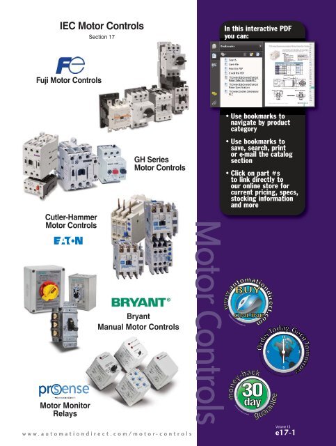
IEC <strong>Motor</strong> <strong>Controls</strong>Section 17In this interactive PDFyou can:Fuji <strong>Motor</strong> <strong>Controls</strong>Cutler-Hammer<strong>Motor</strong> <strong>Controls</strong>GH Series<strong>Motor</strong> <strong>Controls</strong>•Use bookmarks tonavigate by productcategory•Use bookmarks tosave, search, printor e-mail the catalogsection•Click on part #sto link directly toour online store forcurrent pricing, specs,stocking informationand more<strong>Motor</strong> <strong>Controls</strong>BryantManual <strong>Motor</strong> <strong>Controls</strong>Available in the U.S only, if ordered by 6pm ET., additional shipping charges may apply.<strong>Motor</strong> MonitorRelaysVolume 13www.automationdirect.com/motor-controlse17-1
Fuji Electric IEC <strong>Motor</strong> <strong>Controls</strong>AUTOMATIONDIRECT has cooperated with Fuji Electric to offer acomplete line of IEC electric motor controls.The DUO line (SC-E contactors and TK-E overloads) is fully integratedso multiple motor speed controller solutions are possiblewith a minimum number of components. The conventional motorstarters in the DUO line can accommodate electric motors up to100 horsepower at 480VAC. The larger motor contactors featurethe SUPERMAGNET coil for greater reliability and positive pickupand drop-out.Now available: 440-480 VAC and 500-550 VAC Coil VoltagesThe Odyssey Series of contactors and overload relays alsofeatures the SUPERMAGNET coil and come in sizes up to 361A, AC-3 operation (300 horsepower at 480 VAC). Odyssey Seriescontactors are available in four sizes with overload relays to matchany motor to 300 horsepower.Now available: 380-450 VAC and 460-575 VAC Coil VoltagesBoth the DUO and Odyssey lines are available in 24 VAC, 24VDC, 120 VAC, 240 VAC, 380-575 VAC. The motor contactorsare rated up to 690 VAC, 3-phase.Conformance to IEC standards:• Short-circuit protective coordination between protectivedevices and the equipment to be protectedResponse to the international market:• Conformance to CE, IEC, UL, CSA and other internationalstandardsSafety and environmental consideration:• Application of international standards in safety featuressuch as terminals with finger protection• Use of recycled materialsUse contactors for:• Electronic switching• Lighting• Resistive loads• Non-motor related inductive loads• Disconnect switches• VFD bypass/isolationUse starters for:• Inductive motor startingand control• Fulfillment of NEC 430 and 409• NEMA starterreplacement/retrofitDUO Series: SC-E series contactors and TK-E series overload relays1/2 to 100 hp9 - 150A (AC3) rated currentSC-E Series <strong>Contactor</strong> Features• 5 to 100 hp at 480 VAC• cULus and CSA approval, CE mark, meets JIS andIEC standards.• Models SC-E02-xxx to SC-E4-xxx have3-pole maincircuits and come in threesizes with widths of 43mm, 54 mm, and67 mm.• Models SC-E1-xxx to SC-E7-xxx employ a boxterminal structure; allowing wires to be connecteddirectly to the main circuit.• Has a finger-protection terminal structure that preventsthe exposure of live parts.• Models SC-E5-xxx to SC-E7-xxx use a SUPERMAG-NETTM (AC-input/DC-output operation) for highoperating reliabilityTK-E Series Overload Features• Isolated NO and NC contacts can be used with differentpotentials• A high-precision scale for the current adjustmentdial enables easy and exact current setting• The operating status can be visually checked withease• The relays can be manually tripped. A tripfreemechanism is also provided• Base unit can be added to enable separate mountingof the TK-E02, E2, and E3-xxx models• IEC-947, UL, CSA, CETraditional startersFuji’s DUO line offers a complete range of componentsfor building a traditional starter utilizingoverload relays, auxiliary and alarm contacts, andmechanical interlocks to create a reversing unit.Build a reversing starter withDUO line componentsVolume 13e17-2<strong>Motor</strong> <strong>Controls</strong>1 - 8 0 0 - 6 3 3 - 0 4 0 5
Fuji Electric IEC <strong>Motor</strong> <strong>Controls</strong>Odyssey 3N series contactors andmatching overload relaysThe Odyssey series, from 60 to 300 hp at 480 V, uses Fuji’sunique SUPERMAGNET technology for greater reliability.The SUPERMAGNET holds without chattering even if theline voltage drops to 65% of its rated value, preventingcontact and coil damage.3N Series <strong>Contactor</strong> Features• Provides higher current and horsepower capabilitiesthan SC-E series. Designed for reliableuse in applications requiring constant switching,reduced coil energy consumption, andincreased horsepower capabilities.• Available in 154 mm and 169 mm frame widths• SUPERMAGNET for high operating reliability.• Use with Odyssey 3N series overload relays.• IEC-947, UL, CSA, CE3N Series Overload Features• Overload, phase lossprotection• Isolated NO andNC contacts• Ambient temperaturecompensation• Trip indicator• Finger protectionterminals• IEC-947, UL, CSA, CEBM3 SeriesManual <strong>Motor</strong> <strong>Starters</strong>(MMS)Circuit breakers for motor use thatprovide optimal protection by integratingthe functions of a moldedcase circuit breaker and thermaloverload relay into a compact unit.- Rated Current: 0.16 to 32A, 10 to 63A- Short Circuit Current Rating: 100 kA at 240V, 50 kAat 480V, 10 kA at 600V- Widths: 45 mm and 55 mmCHECK OUT OUR PRICES<strong>Motor</strong> <strong>Controls</strong>9 Amp <strong>Contactor</strong>40 Amp <strong>Contactor</strong>AutomationDirectFuji$13.75SC-E02-110VAC$48.75SC-E2-110VACAllen-Bradley$90.00 *100-C09D10$202.00100-C37D0060 to 300 hp at 480 V180 - 361A (AC3) rated currentCombination<strong>Starters</strong>Use Odysseycomponents tobuild a traditionalstarterThe ability to configure combinationstarters for compact,reliable motor protection bycombining a manual motorstarter and a magneticcontactor.GE$110.60CL00A310TJ$257.25CL06A311MJABB$69.58 *A9-30-10-84$264.92 *A40-30-10-84Auxiliary contact blocksMechanical interlocksReversing kitsTerminal CoversReplacement CoilsSurge suppressorsand more!CompanyInformationSystemsOverviewProgrammableControllersField I/OSoftwareC-more &other HMIDrivesSoft<strong>Starters</strong><strong>Motor</strong>s &GearboxSteppers/Servos<strong>Motor</strong><strong>Controls</strong>ProximitySensorsPhotoSensorsLimitSwitchesEncodersCurrentSensorsPressureSensorsTemperatureSensorsPushbuttons/LightsProcessRelays/TimersComm.TerminalBlocks &WiringPowerCircuitProtectionEnclosuresTools10 Amp<strong>Motor</strong> Starter$49.00BM3RHB-010$207.00140M-C2E-C10$100.4$171.03MS325-12.5PneumaticsAppendix* This product includes 1 N.0. Aux contactAll prices are U.S. published prices. AutomationDirect prices are from March 2011 Price List. Allen-Bradley prices taken from www.rockwellautomation.com/en/e-tools 2/21/11 GE prices taken fromwww.grainger.com 2/22/11. . ABB prices taken from www.galco.com 2/22/11. Prices and specifications may vary by dealer and configuration. Prices subject to change without notice.ProductIndexPart #IndexVolume 13w w w . a u t o m a t i o n d i r e c t . c o m / m o t o r - c o n t r o l s <strong>Motor</strong> <strong>Controls</strong> e17-3
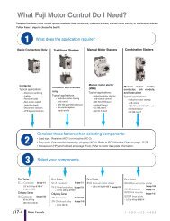
What Fuji <strong>Motor</strong> Control Do I Need?There are four basic motor control options available: Basic contactors, traditional starters, manual motor starters, or combination starters.Follow these 3 steps to choose the best fit.1What does the application require?Basic <strong>Contactor</strong>s Only Traditional <strong>Starters</strong> Manual <strong>Motor</strong> <strong>Starters</strong> Combination <strong>Starters</strong><strong>Contactor</strong>Typical applications:• Electronic switching• Lighting• Resistive loads• Non-motor-relatedinductive loads• Disconnect switches• VFD bypass/isolation<strong>Contactor</strong> and overloadrelayTypical applications:• Inductive motor startingand control• NEC 430 and 409 fulfillment• Nm starterreplacement/retrofitManual motor starter(MMS)Typical applications:• Inductive motor startingand manual control• NEC 430 fulfillment• Lockout/tagout• UL 508, type E• Not AC-4 ratedManual motor starter,contactor, link module,and base plateTypical applications:• Inductive motor startingand control• NEC 430 and 409 fulfillment• Lockout/tagout• UL 508, type F23Consider these factors when selecting components:• Load type: Resistive (AC-1) or inductive (AC-3)• Duty cycle: One direction, reversing, plugging (AC-4); Refer to IEC Utilization Chart on page• Horsepower (HP) and full load amperage (FLA); Refer to motor data plate information.Select your components.17-78Duo SeriesSC-E <strong>Contactor</strong> See page 17-5• 1/2 to 100 hp @ 480 V• 9-150 A (AC3)Odyssey Series3N <strong>Contactor</strong> See page 17-52• 60 to 300 hp• 180-361 A (AC3)Duo SeriesSC-E <strong>Contactor</strong> See page 17-5TK-E Overload relay See page 17-21• 1/2 to 100 hp @ 480 VOdyssey Series3N <strong>Contactor</strong>See page 17-523N Overload relay See page 17-55• 60 to 300 hpDuo SeriesBM3 Manual motor starter• 1/2 to 40 hp @ 480 V See page 17-28Duo SeriesBM3 Manual motor starterSee page 17-28SC-E<strong>Contactor</strong> See page 17-5BZ0L link moduleSee page 17-43BZ0BP base plate• 1/2 to 40 hp @ 480 VVolume 13e17-4<strong>Motor</strong> <strong>Controls</strong>1 - 8 0 0 - 6 3 3 - 0 4 0 5
Fuji Duo Series SC-E <strong>Contactor</strong>sFeatures• 5 to 100 hp at 480 VAC• cULus and CSA approval, CE mark, meetsJIS and IEC standards.• Models SC-E02-xxx to SC-E4-xxx have3-pole main circuits and come in threesizes with widths of 43 mm, 54 mm, and67 mm.• Models SC-E1-xxx to SC-E7-xxx employ abox terminal structure; allowing wires to beconnected directly to the main circuit.• Has a finger-protection terminal structurethat prevents the exposure of live parts.• Models SC-E5-xxx to SC-E7-xxx use aSUPERMAGNET TM (AC-input/DC-outputoperation) for high operating reliabilityand requires no surge suppressor.Small Size• SC-E02-xxx to E05-xxx: 43mm wide• SC-E1-xxx to E2S-xxx: 54mm wide• SC-E3-xxx, E4-xxx: 67mm wide• SC-E5-xxx: 88mm wideModelPriceSC-E2SSafety• Terminals with finger-touch protection(DIN 57106/VDE 0106 Teil100)Utility• Box lug terminal construction• Long electrical life• Easy to wireEnvironmental• Low power consumption• Recycled thermoplastic resin used forplastic parts.• The names of materials are indicated onall major parts to facilitate recyclingSC-E Series <strong>Contactor</strong>s Specifications - UL and CSANominal CoilVoltageSC-E02-24VAC 24VACSC-E02-110VAC 110VACSC-E02-220VAC 220VACSC-E02-440VAC 440-480VACSC-E02-500VAC 500-550VACSC-E02G-24VDC 24VDCSC-E03-24VAC 24VACSC-E03-110VAC 110VACSC-E03-220VAC 220VACSC-E03-440VAC 440-480VACSC-E03-500VAC 500-550VACSC-E03G-24VDC 24VDCSC-E04-24VAC 24VACSC-E04-110VAC 110VACSC-E04-220VAC 220VACSC-E04-440VAC 440-480VACSC-E04-500VAC 500-550VACSC-E04G-24VDC 24VDCSC-E05-24VAC 24VACSC-E05-110VAC 110VACSC-E05-220VAC 220VACSC-E05-440VAC 440-480VACSC-E05-500VAC 500-550VACSC-E05G-24VDC 24VDCTABLE CONTINUED NEXT PAGERated Capacity (HP)3-Phase <strong>Motor</strong>1-Phase<strong>Motor</strong>200V 220–240V 400–480V 550–600V 100–120V220–240VSC-E7Standards & Approvals• UL listed , file E42419, Standard UL 508• cUL listed, file E42419,Standard CSA C 22.2 No.14• VDE 0660• JIS C 8201-4-1• IEC 60947-4-1 / EN 60947-4-1• CE compliantOptional accessories• Auxiliary contact blocks• Coil surge suppression units• Replacement coils for contactor sizesSC-E5 and largerRated AC-3Current (A) [note 1]Rated AC-1Thermal Current(A) [note 2]2 2 5 5 1/3 1 9 203 3 7.5 7.5 1/2 2 12 205 5 10 10 1 3 18 255 7.5 15 15 2 3 25 32Notes: 1. AC3 type loads consist of squirrel cage three-phase motors; occasional, limited jogging duty.2. AC1 non-inductive or slightly inductive loads. Typically resistive loads (i.e. furnaces, ovens, etc.)SCCR Ratings(KA)Rated InsulationVoltage (V)Frame Width(mm)5 690 43CompanyInformationSystemsOverviewProgrammableControllersField I/OSoftwareC-more &other HMIDrivesSoft<strong>Starters</strong><strong>Motor</strong>s &GearboxSteppers/Servos<strong>Motor</strong><strong>Controls</strong>ProximitySensorsPhotoSensorsLimitSwitchesEncodersCurrentSensorsPressureSensorsTemperatureSensorsPushbuttons/LightsProcessRelays/TimersComm.TerminalBlocks &WiringPowerCircuitProtectionEnclosuresToolsPneumaticsAppendixProductIndexPart #IndexVolume 13www.automationdirect.com/motor-controls <strong>Motor</strong> <strong>Controls</strong> e17-5
Fuji Duo Series SC-E <strong>Contactor</strong>sModelPriceSC-E Series <strong>Contactor</strong>s Specifications - UL and CSANominal CoilVoltageSC-E1-24VAC 24VACSC-E1-110VAC 110VACSC-E1-220VAC 220VACSC-E1-440VAC 440-480VACSC-E1-500VAC 500-550VACSC-E1G-24VDC 24VDCSC-E2-24VAC 24VACRated Capacity (HP)3-Phase <strong>Motor</strong>1-Phase<strong>Motor</strong>200V 220–240V 400–480V 550–600V 100–120V220–240VRated AC-3Current (A) [note 1]Rated AC-1Thermal Current(A) [note 2]7.5 10 25 25 2 3 32 50SC-E2-110VAC 110VACSC-E2-220VAC 220VACSC-E2-440VAC 440-480VAC10 15 30 30 3 5 40 6054SC-E2-500VAC 500-550VACSC-E2G-24VDC 24VDCSC-E2S-24VAC 24VACSC-E2S-110VAC 110VACSC-E2S-220VAC 220VACSC-E2S-440VAC 440-480VAC15 20 30 30 3 10 50 65 5SC-E2S-500VAC 500-550VACSC-E2SG-24VDC 24VDCSC-E3-24VAC 24VACSC-E3-110VAC 110VACSC-E3-220VAC 220VACSC-E3-440VAC 440-480VAC20 25 50 50 5 15 65 100SC-E3-500VAC 500-550VAC690SC-E3G-24VDC 24VDCSC-E4-24VAC 24VAC67SC-E4-110VAC 110VACSC-E4-220VAC 220VACSC-E4-440VAC 440-480VAC25 30 50 50 5 15 80 105SC-E4-500VAC 500-550VACSC-E4G-24VDC 24VDCSC-E5-24V 24VAC/VDCSC-E5-100V 110VAC/VDCSC-E5-200V 220VAC/VDC 30 30 60 75 7.5 15 105 15088SC-E5-400V 380-450VACSC-E5-500V 460-575VACSC-E6-24V 24VAC/VDCSC-E6-100V 110VAC/VDCSC-E6-200V 220VAC/VDC 40 40 75 100 10 20 125 150 10100SC-E6-400V 380-450VACSC-E6-500V 460-575VACSC-E7-24V 24VAC/VDCSC-E7-100V 110VAC/VDCSC-E7-200V 220VAC/VDC 50 50 100 125 15 25 150 200 115SC-E7-400V 380-450VACSC-E7-500V 460-575VACNotes: 1. AC3 type loads consist of squirrel cage three-phase motors; occasional, limited jogging duty.2. AC1 non-inductive or slightly inductive loads. Typically resistive loads (i.e. furnaces, ovens, etc.)SCCR Ratings(KA)Rated InsulationVoltage (V)Frame Width(mm)Volume 13e17-6<strong>Motor</strong> <strong>Controls</strong>1-800-633-0405
Fuji Duo Series SC-E <strong>Contactor</strong>sCompanyInformationSystemsOverview<strong>Contactor</strong> TypeRated Capacity (kW)3-Phase <strong>Motor</strong> AC-3 / AC-4Rated InternalThermalAuxilliaryContactCurrent Arrangement(A)200-240V380-440V500-550VSC-E Series <strong>Contactor</strong>s Specifications - IEC600-690VRated Operating Current (A)3-Phase <strong>Motor</strong> AC-3 / AC-4200-240V380-440V500-550V600-690VResistive LoadAC-1200- 380-240V 440VSC-E02(G)-xxx 2.2 / 2.2 4 / 4 4 / NA 4 / NA 9 / 9 9 / 9 7 / NA 5 / NA 20 20 20 -SC-E03(G)-xxx 3 / 3 5.5 / 5.5 5.5 / NA 5.5 / NA 12 / 12 12 / 12 9 / NA 7 / NA 20 20 20 -SC-E04(G)-xxx 4 / 4 7.5 / 7.5 7.5 / NA 7.5 / NA 18 / 18 18 / 18 13 / NA 9 / NA 25 25 25 -SC-E05(G)-xxx 5.5 / 4 11 / 7.5 11 / NA 7.5 / NA 25 / 18 25 / 18 17 / NA 9 / NA 32 32 32 -SC-E1(G)-xxx 7.5 / 7.5 15 / 15 15 / NA 11 / NA 32 / 32 32 / 32 24 / NA 15 / NA 50 50 50 -SC-E2(G)-xxx 11 / 11 18.5 / 18.5 18.5 / NA 15 / NA 40 / 40 40 / 40 29 / NA 19 / NA 60 60 60 -SC-E2S(G)-xxx 15 / 11 22 / 18.5 25 / NA 22 / NA 50 / 40 50 / 40 38 / NA 26 / NA 65 65 65 -SC-E3(G)-xxx 18.5 / 18.5 30 / 30 37 / NA 30 / NA 68 / 68 65 / 65 60 / NA 38 / NA 100 100 100 -SC-E4(G)-xxx 22 / 18.5 40 / 30 37 / NA 37 / NA 80 / 68 80 / 65 60 / NA 44 / NA 105 105 105 -SC-E5-xxx 30 / 30 55 / 55 5 5/ NA 55 / NA 105 / 105 105 / 105 85 / NA 64 / NA 150 150 150 2NO+2NCSC-E6-xxx 37 / 37 60 / 60 6 0 / NA 60 / NA 125 / 125 125 / 125 90 / NA 72 / NA 150 150 150 2NO+2NCSC-E7-xxx 45 / 45 75 / 75 75 / NA 90 / NA 150 / 150 150 / 150 120 / NA 103 / NA 200 200 200 2NO+2NCProgrammableControllersField I/OSoftwareC-more &other HMIDrivesSoft<strong>Starters</strong><strong>Motor</strong>s &GearboxSteppers/Servos<strong>Motor</strong><strong>Controls</strong>ProximitySensorsPhotoSensorsInternal Auxiliary Contact RatingsFrame Size( note 1 )RatedInsulationVoltage (V)Internal Auxiliary Contact Ratings - UL and CSANEMA ICS 5-2000 Ratings ( note 2 )AC RatingsDC RatingsDesignation Making VA Breaking VA Designation Making/Breaking VAE5 to E7-xxx 690 A600 7200 720 Q300 69Notes:1. E02(G) to E4(G) do not have internal auxiliary contact.2. NEMA ICS 5-2000. For more information, refer to Control Circuit Contact Electrical Ratings, see page 17-77.Internal Auxiliary Contact Ratings - IEC, JISBased on IEC 60974-4-1, EN 60947-4-1, JIS C 8201-4-1Frame Size( note 1 )RatedInsulationVoltage (V)RatedThermalCurrent (A)E5 to E7-xxx 690 10Note 1: E02(G) to E4(G) do not have internal auxiliary contact.Making and BreakingCapacity (A)Rated Operational Current (A)AC Voltage Amps AC Voltage AC-15(Ind. load)DC Voltage DC-13(Ind. load)120V 60 120V 6 24V 3220V 30 220V 3 48V 1.5440V 15 440V 1.5 110V 0.55600V 12 600V 1.2 220V 0.27MinimumOperatingVoltage andCurrent5VDC, 3mALimitSwitchesEncodersCurrentSensorsPressureSensorsTemperatureSensorsPushbuttons/LightsProcessRelays/TimersComm.TerminalBlocks &WiringPowerCircuitProtectionEnclosuresToolsPneumaticsAppendixProductIndexPart #IndexVolume 13www.automationdirect.com/motor-controls <strong>Motor</strong> <strong>Controls</strong> e17-7
*Free on ordersover $300** for items shipped fromCumming, GAGet it fast AND free!Free standard 2-day (transit)* shipping is now available for orders over $300,within the U.S. and Puerto Rico. We use our choice of carrier and a combinationof ground and air services that allow us to reach any U.S. destinationwithin 2 days transit time (or less). (Canadian orders use the same method, butmay take up to 3 days in transit based on destination.) Orders placed by6 p.m. EST will ship the same day (with approved company credit or creditcard; LTL items require 5 p.m. order cutoff).Note that the 2-day transit time does not apply for LTL shipping of heavy itemsor drop-shipped items. (We cannot ship heavy items to Hawaii or Puerto Rico.To determine if an item is excluded, check the “Availability” column of theprinted price list.)For orders under $300, you may request that your order ship via the 2-day(transit) method; shipping charges will be added to invoice.For complete details on shipping methods and charges, see Terms andConditions pages TC-4 to 6.* We do not guarantee delivery times of the carriers. AutomationDirect is notresponsible for carrier delays due to weather, mechanical failures or other issues.1-800-633-0405 www.automationdirect.com
Fuji Duo Series SC-E <strong>Contactor</strong>sStandard operatingconditionsThe magnetic contactors are manufacturedfor use in the standard operatingconditions given in the table.AmbientTemperatureHumidityAltitudeAtmosphereStandard Operating ConditionsOperating: -5 to 55°CNo sudden temperature changes resulting in condensation or icing(The average temperature over a 24-hour period must not exceed 35°C)Storage: -40 to 65°C45 to 85%RH2000m or lowerNo excessive dust, smoke, corrosive gases, flammable gases, steam, or saltVibration 10 to 55Hz 15m/s 2Shock 50m/s 2Mounting35mm IEC DIN railmounting (SC-E02 to SC-E4), screw mountingMounting Angle30˚30˚30˚30˚StandardIEC 947-4-1, EN 60947-4-1, VDE 0660JIS C 8201-4-1, JEM 1038UL 508, file E42419; CSA C22.2, file 20479WiringBe sure to perform wiring correctly withreference to the wiring diagrams. Mainterminals for models SC-E02 to SC-E7 arewired using solid wires or stranded wires.Stranded wires or flexible stranded wirescan be connected by twisting themtogether and crimping a sleeve (ferrule)onto them before connecting.Tightening torqueIf wires are not tightened sufficiently, theymay become hot or loosen, resulting in afire, short-circuit, electric shock, or otherpotentially dangerous situation. Tightenwires to the torques specified in thesetables.Solid or Stranded Wire (mm 2 )AWGInsulation Stripping LengthFork TerminalWire Sizes, Tightening Torques - Control CircuitOneTwo0.75 to 2.5 (1 to 1.6 mm diameter)0.75 to 2.5 (1 to 1.6 mm diameter)One 18 to 14Two 18 to 1410 mmMax. 7.7mm wideTerminal Screw Size M3.5ToolPhillips screwdriver, H-type, No. 2 (ISO 8764);ADC part number DN-SP1 or DN-SP2Flat-blade screwdriver, 1 x 5.5 x L-type, B (ISO 2830);ADC part number DN-SS5Tightening Torque (N . m) 0.8 to 1Wire Sizes, Tightening Torques - Main Circuit<strong>Contactor</strong> Type SC-E02-xxx SC-E03-xxx SC-E04-xxx SC-E05-xxxSolid Wire (mm 2 )Stranded Wire (mm 2 )AWGInsulation Stripping LengthOne 0.75 to 4 0.75 to 6Two 1 to 4 1.5 to 6One 0.75 to 4 0.75 to 6Two 1 to 4 1.5 to 6One 12 max. 10 max.Two 12 max. 10 max.11 mmVolume 13e17-10<strong>Motor</strong> <strong>Controls</strong>Terminal Screw SizeToolM4Phillips screwdriver, H-type, No. 2 (ISO 8764);ADC part number DN-SP1 or DN-SP2Flat-blade screwdriver, 1 x 5.5 x L-type, B (ISO 2830);ADC part number DN-SS5Tightening Torque (N . m) 1.2 to 1.51-800-633-0405
Fuji Duo Series SC-E <strong>Contactor</strong>sTightening torque (continued)CompanyInformationSystemsOverviewProgrammableControllersWire Sizes, Tightening Torques - Main Circuit<strong>Contactor</strong> Type SC-E1, E2, E2S-xxx SC-E3, E4-xxx SC-E5, E6-xxx SC-E7-xxxSolid or stranded wire (mm 2 ) 1 0.75 to 35 1.5 to 70 4 to 70 4 to 120Top-OnlyConnectionBottom-OnlyConnectionTop/BottomConnectionToolFlexible stranded wire with sleeve (mm 2 ) 1 0.75 to 25 1.5 to 50 2.5 to 50 2.5 to 95Flexible stranded wire without sleeve (mm 2 ) 0.75 to 25 1.5 to 50 4 to 50 4 to 95AWG 18 to 2 16 to 2/0 12 to 2/0 12 to 250MCMSolid or stripping length (mm) 15 19.5 26.5 28.5Single stranded wire (mm 2 ) 1 0.75 to 25 1.5 to 50 4 to 70 4 to 120Flexible stranded wire with sleeve(mm 2 ) 1 0.75 to 16 1.5 to 35 2.5 to 50 2.5 to 95Flexible stranded wire without sleeve (mm 2 ) 0.75 to 16 1.5 to 35 4 to 50 4 to 95AWG 18 to 3 16 to 1/0 12 to 2/0 12 to 250MCMSheath stripping length (mm) 12.5 16 26.5 28.5Solid or stranded wire(mm 2 ) 1Flexible stranded wire withsleeve (mm 2 ) 1Flexible stranded wire withoutsleeve (mm 2 )AWGTop/bottomTop/bottomTop/bottomTop/bottom0.75 to 25 1.5 to 50 4 to 70 4 to 1200.75 to 16 1.5 to 35 2.5 to 50 2.5 to 950.75 to 16 1.5 to 35 4 to 50 4 to 9518 to 3 16 to 1/0 12 to 2/0 12 to 250MCMPhillips screwdriver, H-type, No.2(ISO 8764);ADC part number DN-SP1 or DN-SP2Flat-blade screwdriver, 1 x 5, 5xLtype,B (ISO 2830);ADC part number DN-SS5Hex. wrench 4 (ISO 2936)Tightening Torque (Nm) 2.5 8 10Self-locking Torque (Nm) 2 1 2Note 1: Stranded wire (0 to 25mm 2 ) consists of 7 wires or less.Stranded wire (35 to 120mm 2 ) consists of 19 wires or less.Flexible stranded wire consists of more number wires thanthe above.Note 2: The tightening bolt must be loosened in order to insert the wire. However, stoploosening the bolt when the anti-drop attachment on the bottom of the bolt reachesthe top edge of the terminal. If a torque exceeding that given in the table is appliedin this state, the retaining bracket may loosen.Field I/OSoftwareC-more &other HMIDrivesSoft<strong>Starters</strong><strong>Motor</strong>s &GearboxSteppers/Servos<strong>Motor</strong><strong>Controls</strong>ProximitySensorsPhotoSensorsLimitSwitchesEncodersCurrentSensorsPressureSensorsTemperatureSensorsPushbuttons/LightsProcessRelays/TimersComm.TerminalBlocks &WiringPowerCircuitProtectionEnclosuresToolsPneumaticsAppendixProductIndexPart #IndexVolume 13www.automationdirect.com/motor-controls <strong>Motor</strong> <strong>Controls</strong> e17-11
Fuji Duo Series SC-E <strong>Contactor</strong>sElectrical durabilityAC-3 duty / SC-E02 to SC-E05-xxx200 - 240V 380 - 440V1000010000Make/break operations ( 10 3 )3-phase motor capacity (kW)and full-load current (A)380 - 440VSC-E02SC-E03SC-E04SC-E055000500030003000200020001000100050050030030020020010010050503030202010101 2 3 510 20 30 50 100 200 300 500 10009A12A18A25A4kW5.5kW7.5kW11kWBreaking current (A)200 - 240V2.2kW3kW4kW5.5kWAC-3 duty / SC-E1 to SC-E7-xxx200 - 240V 380 - 440V100005000100005000300030002000200010005001000500300300200200100501005030302020Make/break operations ( 10 3 )SC-E1SC-E2SC-E2SSC-E3SC-E4SC-E5SC-E6SC-E7101010 20 30 50100 200 300 500 1000 2000 3000 5000 100003-phase motor capacity (kW)and full-load current (A)380 - 440V32A40A50A65A80A105A125A150A15kW18.5kW22kW30kW40kW55kW60kW75kWBreaking current (A)200 - 240V7.5kW11kW15kW18.5kW22kW30kW37kW45kWAC-1 duty / SC-E02 to SC-E7-xxx200 - 240VMake/break operations ( 10 3 )100005000300020001000500300200380 - 440V100005000300020001000500300200SC-E02SC-E03SC-E04SC-E05SC-E1SC-E2SC-E2SSC-E3SC-E4SC-E5SC-E6SC-E71001001 2 351020 30 50 100 200 300 500 100020A25A32A50A60A65A100A105A150A200ABreaking current (A)Volume 13e17-12<strong>Motor</strong> <strong>Controls</strong>1-800-633-0405
Fuji Duo Series SC-E <strong>Contactor</strong>s AccessoriesOptional accessoriesCompanyInformationSystemsOverviewProgrammableControllersField I/OSZ-AS1T auxiliarycontact blockSZ-Z coil surgesuppression unitSC-E <strong>Contactor</strong>SoftwareC-more &other HMIDrivesSZ-AS1T auxiliarycontact blockSoft<strong>Starters</strong><strong>Motor</strong>s &GearboxSteppers/Servos<strong>Motor</strong><strong>Controls</strong>ProximitySensorsPhotoSensorsSZ-A22T auxiliarycontact blockLimitSwitchesEncodersCurrentSensorsAuxiliary contact blocks withterminal coversThe front mounting auxiliary contact blockallows two or four auxiliary contacts to beadded without increasing the mountingarea of the magnetic contactors. The sidemounting auxiliary contact block allowstwo auxiliary contacts to be added to themagnetic contactors without increasing thedepth.Caution on use:1. Front mounting auxiliary contact block andside mounting block cannot be attached toone contactor at the same time.2. Only one front mounting block can beattached to one contactor.3. Where mechanical latch unit is alreadyattached, only side mounting auxiliary contactblock can be attached.4. Where interlock unit is already attached,side mounting auxiliary contact block can beattached on one side only.SZ-A22T SZ-A11T SZ-AS1T SZ-AS2TAuxiliary Contact Blocks with Terminal CoversPart Number Price Applicable <strong>Contactor</strong> MountingNumber ofContactsSZ-A22T SZ-A20T SC-E02(G)-xxx to E4(G)-xxx Front mountingContactArrangement4 2NO + 2NC2NOSZ-A11T 21NO + 1NCSZ-AS1T SC-E02(G)-xxx to E4(G)-xxx2 1NO + 1NCSide mountingSZ-AS2T SC-E5, E6, E7-xxx 2 1NO + 1NCNEMA ICS 5-2000 Ratings ( note 1 )AC RatingsAccessory Auxiliary Contact Ratings - UL and CSADC RatingsDesignation Making VA Breaking VA Designation Making/Breaking VAA600 7200 720 Q300 69more information, refer to Control Circuit Contact Electrical Ratings, page 17-77Accessory Auxiliary Contact Ratings - IEC and JIS continued on next page.Volume 13www.automationdirect.com/motor-controls <strong>Motor</strong> <strong>Controls</strong> e17-13PressureSensorsTemperatureSensorsPushbuttons/LightsProcessRelays/TimersComm.TerminalBlocks &WiringPowerCircuitProtectionEnclosuresToolsPneumaticsAppendixProductIndexPart #Index
Fuji Duo Series SC-E <strong>Contactor</strong>s AccessoriesRatedThermalCurrent (A)10Accessory Auxiliary Contact Ratings - IEC and JISRated operational current (A)Making andBreaking Capacity ACDCat AC (A) Voltage AC-15 (Ind. load) Voltage DC-13 (Ind. load)120V 60 120V 6 24V 3220V 30 220V 3 48V 1.5440V 15 440V 1.5 110V 0.55600V 12 600V 1.2 220V 0.27Minimum OperatingVoltage andCurrent5VDC, 3mACoil surge suppression unitsSZ-Z1 SZ-Z37Suppress surge voltage due to contactorON-OFF operations; easily connect tocontactor coil terminals.Coil Surge Suppression UnitsApplicable <strong>Contactor</strong>Operating CoilPart Number PriceAC Operated DC Operated VoltageSZ-Z1 SC-E02G-xxx to 24-48V AC/DCSC-E02-xxx to E05-xxxSZ-Z2 E05G-xxx100-250V AC/DCSZ-Z31 SC-E1G-xxx to 24-48V AC/DCSC-E1-xxx to -E4xxxSZ-Z32 E4G-xxx100-250V AC/DCSZ-Z4 SC-E02G-xxx to 24-48V AC/DCSC-E02-xxx to E05-xxxSZ-Z5 E05G-xxx100-250V AC/DCSZ-Z34 24-48V AC/DCSC-E1-xxx to E4-xxx -SZ-Z35 100-250V AC/DCSZ-Z36 SC-E1G-xxx to 24-48V AC/DC-SZ-Z37 E4G-xxx100-250V AC/DCSC-E02 to E05380-440V AC/DCSC-E1 to E4380-440V AC/DCDeviceVaristorcapacitor/ resistorNote: Super Magnet Coils on SC-E5, SC-E6, and SC-E7 contactors have internal surge suppression. See diagrambelow.PowersupplyAC or DCINPUTSurgesuppressioncircuitRectifiercircuitIC-circuitVoltagedetectorClosingsignalcircuitSealingsignalcircuitPowerswitchingcircuitCOILReplacement contactor coilsSZ-GSN5-100SC-E Series Replacement <strong>Contactor</strong> CoilsPart Number Price Applicable <strong>Contactor</strong> Coil VoltageSZ-GSN5-100 SC-E5-xxx 100-127VAC 50/60Hz / 100-120VDCSZ-GSN6-100 SC-E6-xxx, SC-E7-xxx 100-127VAC 50/60Hz / 100-120VDCSZ-GSN5-200 SC-E5-xxx 200-250VAC 50/60Hz / 200-240VDCSZ-GSN6-200 SC-E6-xxx, SC-E7-xxx 200-250VAC 50/60Hz / 200-240VDCSZ-GSN5-24 SC-E5-xxx 24-25VAC/ 50/60Hz / 24VDCSZ-GSN6-24 SC-E6-xxx, SC-E7-xxx 24-25VAC/ 50/60Hz / 24VDCReplacement coils are available for contactor sizes SC-E5 and larger only.Replacement coils are not available for coil codes 440VAC, 500VAC, 400V, 500V.Volume 13e17-14<strong>Motor</strong> <strong>Controls</strong>1-800-633-0405
Fuji Duo Series SC-E AccessoriesConnection kits for reversing SC-E contactorsCompanyInformationSystemsOverviewProgrammableControllersField I/OSoftwareSZ-ERW1A SZ-ERW1B SZ-ERW1D SZ-ERW2A SZ-ERW2BC-more &other HMILine SideWiringLoad SideWiringLoad SideWiringLine SideWiringLoad SideWiringDrivesSoft<strong>Starters</strong><strong>Motor</strong>s &GearboxSteppers/Servos<strong>Motor</strong><strong>Controls</strong>SZ-ERW2D SZ-ERW3A SZ-ERW3B SZ-ERW3DProximitySensorsLoad SideWiringLine SideWiringLoad SideWiringLoad SideWiringPhotoSensorsLimitSwitchesConnection KitsPart Number Price Description Use with <strong>Contactor</strong>sSZ-ERW1A Line side reversing connection kit.SZ-ERW1B* Load side reversing connection kit. For wiring load side when using contactors only or with a MMS device.SZ-ERW1D Load side reversing connection kit. For wiring load side when using two contactors with a thermal overload relay.SZ-ERW2A Line side reversing connection kit.SZ-ERW2B* Load side reversing connection kit. For wiring load side when using contactors only or with a MMS device.SZ-ERW2D Load side reversing connection kit. For wiring load side when using two contactors with a thermal overload relay.SZ-ERW3A Line side reversing connection kit.SZ-ERW3B* Load side reversing connection kit. For wiring load side when using contactors only or with a MMS device.SZ-ERW3D Load side reversing connection kit. For wiring load side when using two contactors with a thermal overload relay.* When using the SZ-ERWxB, a TK-E thermal overload relay must be separately mounted and wired using an SZ-HxEbase. To assemble a TK-E overload directly to the contactor use a SZ-ERWxD load side connection kit.Mechanical interlock unitPartNumberSZ-RM Price DescriptionMechanical Interlock UnitUsed when building a reversing starter. Prevents both contactors frombeing pulled in at once.SC-E02-xxx to SC-E05-xxxSC-E1-xxx to SC-E2S-xxxSC-E3-xxx to SC-E4-xxxUse with <strong>Contactor</strong>sSC-E02-xxx to SC-E4-xxxEncodersCurrentSensorsPressureSensorsTemperatureSensorsPushbuttons/LightsProcessRelays/TimersComm.TerminalBlocks &WiringPowerCircuitProtectionEnclosuresToolsSZ-RMNOTE: Mechanical interlock unit cannot be used with SC-E5-xxx through E7-xxx contactors.PneumaticsParts for reversing Fuji SC-E contactors• SC-E (<strong>Contactor</strong>s - qty. 2)• SZ-ERWxA (Line side connection kit - qty. 1)• SZ-ERWxB* (Load side connection kit - qty. 1)• SZ-RM (Mechanical interlock - qty. 1)• SZ-AxxT (Auxiliary contact blocks - qty. 1)AppendixProductIndexPart #Indexwww.automationdirect.com/motor-controls <strong>Motor</strong> <strong>Controls</strong> e17-15
Fuji Duo Series SC-E <strong>Contactor</strong>sDimensions (mm)Wiring diagrams<strong>Contactor</strong>s<strong>Contactor</strong>sSC-E02, E03, E04, E05-xxx91(Rail height 15)818.5 61Weight: 0.33 kgMass: 0.33kg(28) * 2 Main(68) * 1terminal M4 43* 249 20Coil terminalM3.58018.5(to 20.5)(48 to)52* 1 13 10.5 Mounting hole2-M4Use the two mounting holes on a diagonal lineor to mount contactor: 35 60 : 35 (48 to) 52Panel drilling34351214.560SC-E02 to E05-xxxSC-E1 to E4-xxxSC-E02G to E05G-xxxSC-E1G to E4G-xxxSC-E2S, E2SG-xxx* 1 * 153 61 1/L1 3/L2 5/L3 83 7154 62 2/T1 4/T2 6/T3 84 72A1A2SC-E1, E2, E2S-xxx106 (Rail height 15) (28) * 29665.510.5 2* 2Weight:Mass :0.580.58kgkgMainterminal* 1(79)* 15416.5Coil terminalM3.518.55790580Mounting hole2-M4Use the two mounting holes on a diagonal lineor to mount contactor: 45 75 : 45 (38 to 46) 80Panel drilling45(38 to 46)21459.575SC-E5, E6, E7-xxx* 153 61 13 21 1/L1 3/L2 5/L3 43 31 83 7154 62 14 222/T1 4/T2 6/T344 32* 1 In case of aux. contact 4NO+4NC84* 172A1A2SC-E3, E4-xxx* 1121 (Rail height 15) (28) * 211172.5Main(91)* 2 * 110.5 2.5terminal67Weight: Mass: 1.1kgkg20.5Coil terminalM3.577 19.5112Mounting hole2-M4Use the two mounting holes on a diagonal lineor to mount contactor: (55 to) 60 90 : (54 to) 60 90Panel drilling(54 to)6021(55 to)6090 13Volume 13e17-16<strong>Motor</strong> <strong>Controls</strong>1-800-633-0405
Fuji Duo Series SC-E <strong>Contactor</strong>sDimensions (mm)<strong>Contactor</strong>sSC-E5-xxxPanel drilling132MainCoil terminalterminal77(111)* 1 M3.532.7 48870AuxiliaryterminalM3.513.5CompanyInformationSystemsOverviewProgrammableControllersField I/OSoftwareC-more &other HMIDrives12915575Soft<strong>Starters</strong><strong>Motor</strong>s &GearboxWeight: 2.0 kgMass: 2.0kg* 1 Side mounting aux. contact block* 2 Front mounting aux. contact block32Mounting hole2-M4Steppers/Servos<strong>Motor</strong><strong>Controls</strong>SC-E6-xxx138Mainterminal77 (123)38.8 4 Auxiliary 100terminalM3.5* 1Coil terminalM3.5143 13.5169Panel drilling(80 to)90110ProximitySensorsPhotoSensorsLimitSwitchesEncodersCurrentSensorsWeight: 2.6 kgMass: 2.6kg32Mounting hole2-M5PressureSensorsSC-E7-xxx14038.876.8MainterminalAuxiliaryterminalM3.5Coil terminalPanel drillingM3.5(138) * 1115 (80 to)90146 14.5175110TemperatureSensorsPushbuttons/LightsProcessRelays/TimersComm.Weight: 2.9 kgMass: 2.9kg35Mounting hole2-M5TerminalBlocks &WiringPowerSC-E02G, E03G, E04G, E05G-xxx118 (Rail height 15)Main(28) * 2terminal88 108M48.5(68)43* 1Coil terminalM3.518.5(to 20.5)Panel drilling3414.5CircuitProtectionEnclosures49 2080(48 to)521260ToolsPneumaticsAppendixWeight: 0.59 kgMass: 0.59kg* 2* 11310.5Mounting hole2-M4Use the two mounting holes on a diagonal lineor to mount contactor35 60 : 35 (48 to) 52Volume 13www.automationdirect.com/motor-controls <strong>Motor</strong> <strong>Controls</strong> e17-1735ProductIndexPart #Index
Fuji Duo Series SC-E <strong>Contactor</strong>sDimensions (mm)<strong>Contactor</strong>sSC-E1G, E2G, E2SG-xxx130 (Rail height 15)121.59110.5 2Weight: 0.79 kgMass: 0.79kg* 1 Side mounting aux. contact block* 2 Front mounting aux. contact block* 2(28)(79)Mainterminal 54* 1* 2 * 116.5Coil terminalM3.518.55790580Mounting hole2-M4Panel drilling45(38 to 46)2145Use the two mounting holes on a diagonal lineor to mount contactor: 45 75 : 45 (38 to 46) 80SC-E3G, E4G-xxx140 (Rail height 15) (28)Panel drilling13091.5MainCoil terminal(91)terminalM3.510.5 2.5 67(54 to)60Weight: Mass: 1.4kgkgDimensions-mm* 2 * 2 * 1 * 1* 1 Side mounting aux. contact block* 2 Front mounting aux. contact blockAuxiliary contact blocks - front mounting20.577 19.5112Mounting hole2-M421(55 to)60Use the two mounting holes on a diagonal lineor to mount contactor: (55 to) 60 90 : (54 to) 60 9013909.575Wiring diagramsSZ-A22T, A20T, A11TSZ-A22T, A20T, A11T for SC-E02 (G)-xxx to E4 (G)-xxxM3.5 7.7 M3.5 7.728492849<strong>Contactor</strong> with aux. contact blockCApprox3ABAB2NO1NO+1NC53 6354 6453 6154 6211 Approx 105 25 3 43A22TSZ-A20T, A11T1024Mass: Weight: 36g 36 gMass: Weight: 20g 20 g2NO+2NC53 61 71 8354 62 72 84TypeSC-E02, E03, E04, E05-xxxSC-E1, E2, E2S-xxxSC-E3, E4-xxxSC-E02G, E03G, E04G, E05(G)-xxxSC-E1G, E2G, E2SG-xxxSC-E3G, E4G-xxxA435467435467B80901128090112C109124139136149.5158Volume 13e17-18<strong>Motor</strong> <strong>Controls</strong>1-800-633-0405
Fuji Duo Series SC-E <strong>Contactor</strong>sCompanyInformationSystemsOverviewDimensions (mm)Auxiliary contact blocks - side mountingSZ-AS1T for SC-E02(G)-xxx to E4(G)-xxx4559.52843Weight: 28 gMass: 28gM3.57.712 7.5TypeSC-E02, E03, E04, E05-xxxSC-E1, E2, E2S-xxxSC-E3, E4-xxxSC-E02G, E03G, E04G, E05(G)-xxxSC-E1G, E2G, E2SG-xxxSC-E3G, E4G-xxx<strong>Contactor</strong> with aux. contact blockCA677891677891A12 D 12B80901128090112C815467108121.5130BD435467435467Wiring diagrams1 N.O. + 1 N.C.Mounted on right side71 8372 84Mounted on left side53 6154 62ProgrammableControllersField I/OSoftwareC-more &other HMIDrivesSoft<strong>Starters</strong><strong>Motor</strong>s &GearboxSteppers/Servos<strong>Motor</strong><strong>Controls</strong>ProximitySensorsPhotoSensorsSZ-AS2T for SC-E5 to E7-xxx<strong>Contactor</strong> with aux. contact blockM3.564.54728CBA12 D 121 N.O. + 1 N.C.Mounted on right side71 8372 84Mounted on left side53 61LimitSwitchesEncodersCurrentSensorsPressureSensorsTemperatureSensorsPushbuttons/Lights47.5Weight: 40 gMass: 40g7.712 7TypeSC-E5-xxxSC-E6-xxxSC-E7-xxxA112124139B155169175C132138140D8810011554 62ProcessRelays/TimersComm.TerminalBlocks &WiringPowerCircuitProtectionEnclosuresToolsPneumaticsAppendixProductIndexPart #IndexVolume 13www.automationdirect.com/motor-controls <strong>Motor</strong> <strong>Controls</strong> e17-19
Fuji Duo Series SC-E <strong>Contactor</strong>sDimensions (mm)Coil surge suppression unitsSZ-Z1, Z2, Z4, Z51427 102615Wiring diagramsSC-E02 to E05-xxx + SZ-Z1, Z2(Built-in varistor)Weight: 14 gMass: 14gSC-E02 to E05-xxx + SZ-Z4, Z5(Built-in capacitor/resistor)CRSZ-Z31, Z32, Z34, Z35, Z36, Z3713.526 12.537SC-E1 to E4-xxx + SZ-Z31, Z32(Built-in varistor)30Weight: 15 gMass: 15gSC-E1 to E4-xxx + SZ-Z34, Z35(Built-in capacitor/resistor)SC-E1G to E4G-xxx + SZ-Z36, Z37(Built-in capacitor/resistor)CRVolume 13e17-20<strong>Motor</strong> <strong>Controls</strong>1-800-633-0405
Fuji Duo Series TK-E Overload RelaysTK-E series thermaloverload relays withopen-phaseprotective deviceFeatures• This relay protects motor windings fromburning due to overloads, locked rotor current,or open-phases• Maintenance and inspection safety hasbeen improved by employing a finger protectionmechanism to cover exposed terminals(conforms to DIN 57106, VDE 0106Teil 100)• Isolated NO and NC contacts can be usedwith different potentials• A high-precision scale for the currentadjustment dial enables easy and exactcurrent setting• The operating status can be visuallychecked with ease• The relays can be manually tripped. A tripfreemechanism is also provided• Base unit can be added to enable separatemounting of the TK-E02, E2, and E3-xxxmodelsTK-E Series OverloadsPart Number Price Amperage FrameAdjustment Width/Range (A) <strong>Contactor</strong>TK-E02-15 0.1 - 0.15TK-E02-20 0.13 - 0.2TK-E02-24 0.15 - 0.24TK-E02-30 0.2 - 0.3TK-E02-36 0.24 - 0.36TK-E02-54 0.36 - 0.54TK-E02-72 0.48 - 0.72TK-E02-96 0.64 - 0.96TK-E02-120 0.8 - 1.2TK-E02-145 0.95 - 1.45TK-E02-220 1.4 - 2.2TK-E02-260 1.7 - 2.6TK-E02-340 2.2 - 3.4TK-E02-420 2.8 - 4.2TK-E02-600 4.0 - 6.0TK-E02-800 5.0 - 8.0TK-E02-900 6.0 - 9.0TK-E02-1100 7.0 - 11.0TK-E02-1300 9.0 - 13.0TK-E02-1800 12 - 18TK-E02-2200 16 - 22TK-E02-2500 20 - 2553mmSC-E02(G)throughSC-E05(G)For separatemounting,use withoptional baseunit SZ-HCEon page17-26TK-E02-900TK-E2-800StandardsUL listed, file E44592, Standard UL 508cUL listed, file E44592, CSA C22.2 No. 14IEC 60947-4-1, EN60947-4-1VDE 0660, JIS C 8201-4-1CE CompliantTK-E Series Overloads (continued)Part Number Price Amperage FrameAdjustment Width/Range (A) <strong>Contactor</strong>TK-E2-600 4 - 6TK-E2-800 5 - 8TK-E2-900 6 - 9TK-E2-1100 7 - 11TK-E2-1300 9 - 13TK-E2-1800 12 - 18TK-E2-2600 18 - 26TK-E2-3600 24 - 36TK-E2-4200 32 - 42TK-E2-5000 40 - 50TK-E2-5400 44 - 54TK-E3-1100 7 - 11TK-E3-1300 9 - 13TK-E3-1800 12 - 18TK-E3-2600 18 - 26TK-E3-3600 24 - 36TK-E3-4000 28 - 40TK-E3-5000 34 - 50TK-E3-6500 45 - 65TK-E3-6800 48 - 68TK-E3-8000 64 - 8054mmSC-E1(G)throughSC-E2S(G)For separatemounting,use withoptional baseunit SZ-HDEon page17-2668mmSC-E3(G)throughSC-E4(G)For separatemounting,use withoptional baseunit SZ-HEEon page17-24TK-E3-5000TK-E5-3600TK-E6-6500TK-E Series Overloads (continued)Part Number Price Amperage FrameAdjustment Width/Range (A) <strong>Contactor</strong>TK-E5-2600 18 - 26TK-E5-3600 24 - 36TK-E5-4000 28 - 40 76.5mmTK-E5-5000 34 - 50TK-E5-6500 45 - 65 SC-E5TK-E5-9500 65 - 95TK-E5-10500 85 - 105TK-E6-6500 45 - 65TK-E6-8000 53 - 80 100mmTK-E6-9500 65 - 95SC-E6TK-E6-12500 85 - 125 SC-E7TK-E6-16000 110 - 160CompanyInformationSystemsOverviewProgrammableControllersField I/OSoftwareC-more &other HMIDrivesSoft<strong>Starters</strong><strong>Motor</strong>s &GearboxSteppers/Servos<strong>Motor</strong><strong>Controls</strong>ProximitySensorsPhotoSensorsLimitSwitchesEncodersCurrentSensorsPressureSensorsTemperatureSensorsPushbuttons/LightsProcessRelays/TimersComm.TerminalBlocks &WiringPowerCircuitProtectionEnclosuresToolsPneumaticsAppendixProductIndexPart #IndexVolume 13www.automationdirect.com/motor-controls <strong>Motor</strong> <strong>Controls</strong> e17-21
Fuji Duo Series <strong>Contactor</strong> and OverloadRelay Selection TablesASC-E <strong>Contactor</strong>B+ =TK-E Overload Relay100-240V Single Phase <strong>Motor</strong> (1/3 to 25 hp)Step 1. Select a contactor from page 17-5 based on motor voltage and horsepower.Step 2. Select an overload relay from page 17-21 based on motor full load current.Check the data plate on the motor for the hp, volts and full-rated amps.<strong>Motor</strong>HP 5 Volts 460 Phase 3 Type PRPM 1725 Amps 7.6 Hz 60 SF 1.15DesignB AMB 40°C Insul Class F<strong>Motor</strong> horsepowerDuty Cont Encl TEFC Code K<strong>Motor</strong> voltage<strong>Motor</strong> full-load rated amperage (FLA)Three Phase <strong>Motor</strong>s - Refer to tables on following pageStep 1. Select a SC-E contactor from Column A based on motor voltage,and horsepower.Step 2. Select a TK-E overload relay from Column B to work with the SC-Econtactor selected in Step 1. The motor full load current (FLA)should be within the adjustable current range of the overload relay.Volume 13e17-22<strong>Motor</strong> <strong>Controls</strong>1-800-633-0405
Fuji Duo Series Overload RelaySelection Tables220-240V 3-Phase <strong>Motor</strong> (0.5 to 50 hp) 1Overload Relay Selection for 220–240V 3-phase motors<strong>Motor</strong> Rating A B<strong>Motor</strong> Full LoadOverload Relay<strong>Motor</strong> HP Amperage <strong>Contactor</strong>(FLA) 2Part NumberAdjustableCurrent Range1/2 2.2TK-E02-260 1.7 to 2.6 Amps3/4 3.5 TK-E02-420 2.8 to 4.2 Amps1 4.2 SC-E02-xxxx TK-E02-600 4 to 6 Amps1-1/2 6 TK-E02-800 5 to 8 Amps2 6.8 TK-E02-900 6 to 9 Amps3 9.6 SC-E03-xxxx TK-E02-1300 9 to 13 Amps5 15.2 SC-E04-xxxx TK-E02-1800 12 to 18 Amps7-1/2 22 SC-E05-xxxx TK-E02-2500 20 to 25 Amps10 28 SC-E1-xxxx TK-E2-3600 24 to 36 Amps15 42 SC-E2-xxxx TK-E2-4200 32 to 42 Amps20 54 SC-E3-xxxx TK-E3-6500 45 to 65 Amps25 68 SC-E4-xxxx TK-E3-6800 48 to 68 Amps30 80 SC-E5-xxxx TK-E5-9500 65 to 95 Amps40 104 SC-E6-xxxx TK-E6-12500 85 to 125 Amps50 130 SC-E7-xxxx TK-E6-16000 110 to 160 AmpsNote 1: For 220-240 V three-phase motors up to 150 hp refer to the Fuji Odyssey series.Note 2: Per NEC 2005 table 430.250440-480V 3-Phase <strong>Motor</strong> (0.5 to 100 hp) 1Overload Relay Selection for 440–480V 3-phase motors<strong>Motor</strong> Rating A B<strong>Motor</strong> Full LoadOverload Relay<strong>Motor</strong> HP Amperage <strong>Contactor</strong>(FLA) 2Part NumberAdjustableCurrent Range1/2 1.1 SC-E02-xxxx TK-E02-145 0.95 to 1.45 Amps3/4 1.6 SC-E02-xxxx TK-E02-220 1.4 to 2.2 Amps1 2.1 SC-E02-xxxx TK-E02-260 1.7 to 2.6 Amps1-1/2 3.0 SC-E02-xxxx TK-E02-420 2.8 to 4.2 Amps2 3.4 SC-E02-xxxx TK-E02-420 2.8 to 4.2 Amps3 4.8 SC-E02-xxxx TK-E02-600 4 to 6 Amps5 7.6 SC-E02-xxxx TK-E02-900 6 to 9 Amps7 1/2 11 SC-E03-xxxx TK-E02-1300 9 to 13 Amps10 14 SC-E04-xxxx TK-E02-1800 12 to 18 Amps15 21 SC-E05-xxxx TK-E02-2500 20 to 25 Amps20 27 SC-E1-xxxx TK-E2-3600 24 to 36 Amps25 34 SC-E1-xxxx TK-E2-4200 32 to 42 Amps30 40 SC-E2-xxxx TK-E2-4200 32 to 42 Amps40 52 SC-E3-xxxx TK-E3-6500 45 to 65 Amps50 65 SC-E5-xxxx TK-E3-6800 48 to 68 Amps60 77 SC-E5-xxxx TK-E5-9500 65 to 95 Amps75 96 SC-E6-xxxx TK-E6-12500 85 to 125 Amps100 124 SC-E7-xxxx TK-E6-16000 110 to 160 AmpsNote 1: For 440-480 V three-phase motors up to 300 hp refer to the Fuji Odyssey series.Note 2: Per NEC 2005 table 430.250CompanyInformationSystemsOverviewProgrammableControllersField I/OSoftwareC-more &other HMIDrivesSoft<strong>Starters</strong><strong>Motor</strong>s &GearboxSteppers/Servos<strong>Motor</strong><strong>Controls</strong>ProximitySensorsPhotoSensorsLimitSwitchesEncodersCurrentSensorsPressureSensorsTemperatureSensorsPushbuttons/LightsProcessRelays/TimersComm.TerminalBlocks &WiringPowerCircuitProtectionEnclosuresToolsPneumaticsAppendixProductIndexPart #IndexVolume 13www.automationdirect.com/motor-controls <strong>Motor</strong> <strong>Controls</strong> e17-23
Fuji Duo Series TK-E Overload RelaysAmbientTemperatureHumidityAtmosphereStandard Operating ConditionsOperating: -5 to 55°CNo sudden temperature changes resulting incondensation or icing(The average temperature over a 24-hour period must not exceed 35°C)Storage: -40 to 65°C45 to 85%RHVibration 10 to 55Hz, 15m/s 2Shock 50m/s 2No excessive dust, smoke, corrosive gases, flammable gases, steam, or saltModelApplicable <strong>Contactor</strong>Non-reversingAuxilliaryContactTripClass IEC60947-4-1SpecificationsNo. ofHeaterElementsPowerConsumptionper Pole (VA)2.2TK-E02-xxxTK-E2-xxxSC-E02, E03, E04, E05-xxxSC-E1, E2, E2S-xxx 3.8TK-E3-xxx SC-E3, E4-xxx 1NO+1NC 10A 36.6TK-E5-xxx SC-E5-xxx 6.6TK-E6-xxx SC-E6, E7-xxx 8.0FeaturesOverload, open-phase protection,Ambient temperature compensation,Manual/auto reset selectable,Manual trip mechanism,Trip indicatorModelRatedInsulationVoltage (V)Auxiliary Contact Ratings - UL and CSANEMA ICS 5-2000 Ratings ( note 1 )AC RatingsDC RatingsDesignation Making VA Breaking VA Designation Making/Breaking VATK-E02-xxxto TK-E6-xxx690 B600 3600 360 R300 28Notes:1. NEMA ICS 5-2000. For more information, refer to Control Circuit Contact Electrical Ratings, page 17-77.Auxiliary contact ratings - JIS and IECModelRated InsulationVoltage (A)Rated ThermalCurrent (A)Rated Operational Current (A)AC Voltage(V)AC15(Ind. load)DC Voltage(V)DC13(Ind. load)Minimum Voltageand Current24 3 (0.3) * 24 1.1 (0.3)100-120 2.5 (0.3) * 100-120 0.28TK-E02-xxx 690 5200-240 2 (0.3) * 200-240 0.14380-440 1 (0.3) *500-600 0.6 (0.3) *TK-E2-xxx24 3 (0.5) * 24 1.1 (0.3)TK-E3-xxx 100-120 2.5 (0.5) * 100-120 0.28TK-E5-xxx 690 5200-240 2 (0.5) * 200-240 0.14TK-E6-xxx380-440 1 (0.5) *500-600 0.6 (0.5) *3VDC, 5mA3VDC, 5mANote: * In case of auto-reset type NO contact.Volume 13e17-24<strong>Motor</strong> <strong>Controls</strong>1-800-633-0405
Fuji Duo Series TK-E Overload RelaysWiringBe sure to wire the relays correctly usingthe wiring diagrams on the supplied installationsheets. Main terminals for modelsTK-E02-xxx to TK-E6-xxx are wired usingsolid wires or stranded wires. Strandedwires or flexible stranded wires can beconnected by twisting them together andcrimping a sleeve (ferrule) onto thembefore connecting.Tightening torqueIf wires are not tightened sufficiently, theymay become hot or loosen and result in afire, short-circuit, electric shock, or someother potentially dangerous situation. Besure to tighten the wires to the torquesspecified in these tables.Wire Sizes, Tightening Torques - Main CircuitThermal Overload Relay Model TK-E2-xxx TK-E3-xxx TK-E5-xxx TK-E6-xxxSingle Stranded Wire (mm 2 ) 0.75 to 16 1.5 to 35 16 to 70Flexible Stranded Wire with Sleeve (mm 2 ) 0.75 to 16 1.5 to 35 16 to 70Flexible Stranded Wire without Sleeve (mm 2 ) 0.75 to 16 1.5 to 35 16 to 70AWG 6 max. 2 max. 00 max.Insulation Stripping LengthToolPhillips screwdriver, H-type, No. 2 (ISO 8764);ADC part number DN-SP1 or DN-SP2Flat-blade screwdriver, 1 x 5.5 x L-type, B (ISO 2830);ADC part number DN-SS5Hex. wrench 4 (ISO 2936)Tightening Torque (N . m) 2.5 6 10Note: Stranded wire (0 to 25mm 2 ) consists of 7 wires or less. Stranded wire (35 to 120mm 2 ) consists of 19 wires or less. Flexible stranded wire consists of more wiresthan the above.18 mm21 mm 23 mmCompanyInformationSystemsOverviewProgrammableControllersField I/OSoftwareC-more &other HMIDrivesSoft<strong>Starters</strong><strong>Motor</strong>s &GearboxSteppers/Servos<strong>Motor</strong><strong>Controls</strong>ProximitySensorsPhotoSensorsLimitSwitchesEncodersCurrentSensorsPressureSensorsTemperatureSensorsPushbuttons/LightsProcessRelays/TimersWire Sizes, Tightening Torques - Main CircuitThermal Overload Relay Type TK-E02-xxxSolid WireOne 0.75 to 4(mm 2 )Two 1 to 4Stranded Wire One 0.75 to 4(mm 2 )Two 1 to 4AWGOne 12 max.Two 12 max.Insulation Stripping Length11 mm(mm)Terminal Screw SizeM4Phillips screwdriver, H-type, No. 2 (ISO 8764);ToolADC part number DN-SP1 or DN-SP2Flat-blade screwdriver, 1 x 5.5 x L-type, B (ISO2830); ADC part number DN-SS5Tightening Torque[N . m (lb . in)]1.2 to 1.5 (11 to 13)Wire Sizes, Tightening Torques - Control CircuitSingle Stranded Wire(mm 2 )AWGInsulation Stripping Length(mm)Fork TerminalOne 0.75 to 2.5 ( ø 1 to ø 1.6)Two 0.75 to 2.5One 18 to 14Two 18 to 14Terminal Screw Size M3.5ToolTightening Torque[N . m (lb . in)]Max. 7.7mm wide (R2-3.5)Phillips screwdriver, H-type, No. 2 (ISO 8764);ADC part number DN-SP1 or DN-SP2Flat-blade screwdriver, 1 x 5.5 x L-type, B (ISO2830); ADC part number DN-SS50.8 to 1 (7 to 9)10 mmComm.TerminalBlocks &WiringPowerCircuitProtectionEnclosuresToolsPneumaticsAppendixProductIndexPart #IndexVolume 13www.automationdirect.com/motor-controls <strong>Motor</strong> <strong>Controls</strong> e17-25
Fuji Duo Series TK-E Overload RelaysOperating characteristicsTK-E02-xxxOperating timeSecond Minute80503020108532604030201086432Open-phase(cold start)Reference temperature: 20° COvercurrent (cold start)1 Overcurrent (hot start)0.80.60.40.30.8 1 1.5 2 3 4 5 6 7 8 9 10 15x Ie (A)Multiple of setting valueOperating timeSecond MinuteTK-E2 to E6 -xxx80503020108532604030201086432Open-phase(cold start)Reference temperature: 20° COvercurrent (cold start)1 Overcurrent (hot start)0.80.60.40.30.8 1 1.5 2 3 4 5 6 7 8 9 10 15Multiple of setting valuex Ie (A)Optional accessoriesBase units for separatemountingSZ-HCE Base UnitAllows TK-E02, E2, and E3 series thermaloverload relays to be separately mountedto 35mm wide DIN rail, or screwmounted to panel.Install thermal overload relay ontobase unit as shown. Relay can nowbe installed onto DIN rail or panel.Mounting Base UnitPart Number Applicable Overload RelaysPriceTK-E02-145 Thermal Overload RelaySZ-HCE TK-E02-xxx SZ-HDE TK-E2-xxx SZ-HEE TK-E3-xxx SZ-HDE8.5 75.5 99Main 1terminal546.5 7SZ-HCESZ-HCE8367.57MainterminalM48515Mountinghole2-M4476072619099SZ-HDE8.559100.5SZ-HEE8.5 78 1045Main154680.5968109.535843Mountinghole2-M483553SZ-HEE641065Mountinghole2-M468Volume 13e17-26<strong>Motor</strong> <strong>Controls</strong>1-800-633-0405
Fuji Duo Series TK-E Overload RelaysCompanyInformationSystemsOverviewDimensions (mm)ProgrammableControllersOverload relaysField I/OTK-E02-xxxReset button(Resetting28stroke: 3mm)10 13 7.7B77 3AAux. terminalM3.5(NO)MainterminalM4C26.55314143746.5DAux.terminalM3.5(NC)TK-E2-xxx50.592AB5Reset button(Resettingstroke: 4mm)Aux.terminalM3.5(NO)78.5C27.57.316.5 16.5547.85367.510.5DAux.terminalM3.5(NC)MainterminalSoftwareC-more &other HMIDrivesSoft<strong>Starters</strong><strong>Motor</strong>s &GearboxSteppers/Servos<strong>Motor</strong><strong>Controls</strong><strong>Contactor</strong>SC-E02 to 05SC-E02G to 05GTK-E3-xxxA B80.5 -- 107.555.597.5 5B<strong>Contactor</strong>SC-E3, E4SC-E3, E4GAA B107.5 -- 126.5C4949Reset button(Resettingstroke: 4mm)Aux.terminalM3.5(NO)C2910.4C79.579.5D127.5127.520.5 20.5Weight: 0.13kg4.9Mainterminal20.5 20.5 13.568D1801809.8766089.5DAux.terminalM3.5(NO)Weight: 0.34kg<strong>Contactor</strong>SC-E1 to E2SSC-E1G to E2SGTK-E5-xxxA97-B-123C63.563.5D149149On-contactor mounting only29Reset button3.7(Resettingstroke: 4mm)5910.4101 5106Weight: 0.37kgAux.terminalM3.5(NO)115106.5326876.59.83267Weight: 0.25kg105235Aux.terminalM3.5(NO)4.9Main terminalMounting20.5 20.5 13.5hole2-M4ProximitySensorsPhotoSensorsLimitSwitchesEncodersCurrentSensorsPressureSensorsTemperatureSensorsPushbuttons/LightsProcessRelays/TimersComm.TK-E6-xxxOn-contactor mounting onlyWiring diagramTerminalBlocks &WiringPowerAux.terminalM3.5(NO)BD32 329.84.9Aux.terminalM3.5(NO)77.5107.5122C3-heater element(NO) (NC)97 95CircuitProtectionEnclosuresTools74118A<strong>Contactor</strong>SC-E6SC-E7A12312343605 Reset button 15(ResettingB124129C266.52743232 1835100D4550MainterminalWeight: 0.71kg2/T1 4/T2 6/T3 98 96(NO) (NC)PneumaticsAppendixProductIndexPart #IndexVolume 13www.automationdirect.com/motor-controls <strong>Motor</strong> <strong>Controls</strong> e17-27
Fuji Duo Series Manual <strong>Motor</strong> <strong>Starters</strong>The manual motor starter is a protective device for motor use thatprovides optimal protection by integrating the functions of a moldedcase circuit breaker and thermal overload relay into a compactunit. Since Fuji’s MMS is UL listed for Category E self-protectedmotor control, it can be used for motor branch circuit protectionwithout the need for additional protection such as fuses or moldedcase circuit breakers. The MMS is available in a 32A version witha 45 mm frame width, and a 63A version with a 55 mm framewidth. Both MMS versions have high breaking capacities, up to100,000A in some ranges. A wide range of accessories is available,including shunt trips and undervoltage releases.IP20 finger-safe terminalsFront and side mounted auxiliaryand alarm contact blocksAvailable in two frame sizes:45 mm up to 32 amps and55 mm up to 63 ampsAdjustable current range for motoroverload with anti-tamper coverDIN-Rail mounting eliminates theneed for additional fasteners(Screw mounting also available)Manual ON/OFF control with tripindication and reset capabilityProtects against motor overload,short circuit and phase lossLockout capability for personnelsafety during maintenanceLabel for easy identificationExternal handle kits available forcontrolling the MMS from theoutside of the enclosureUL Type E rated for self-protectedbranch motor control, eliminatingthe need for additional fuses orbreakersManual trip testUp to 50 KA breaking capacity at 480 VACTrip-free design prevents holding theMMS in the ON position during a tripconditionCompatible with Fuji SC-E seriescontactors for a complete motorcontrol solutionAuxiliary andalarm contactblocksShunt trips andundervoltagereleasesMMS external handlesMMS BusbarsVolume 13e17-28<strong>Motor</strong> <strong>Controls</strong>1-800-633-0405
Fuji Duo Series Manual <strong>Motor</strong> <strong>Starters</strong>CompanyInformationSystemsOverviewGeneral InformationProgrammableControllersFeatures• Adjustable thermal-magnetic trip• Available in two frame sizes,45 mm width and 55 mm width• A wide motor capacity range up to 40 hp,3-phase (440/480 VAC, 63A); 60 hp @ 600 V• Rotary handle operators• On/Off and trip state indicators for allframes• Max. breaking capacity of 100 kA (240 VAC)• Common accessories to reduce inventory• A wide rated operational current range ofup to 32A for the 45 mm wide and 63A forthe 55 mm wide starters• ON/OFF and trip indicators for instantstatus recognition• Accessories such as auxiliary contactblocks, shunt trip devices, and undervoltagetrip devices are compatible with the45 mm and 55 mm wide frame sizes• External operating handles are available asoptional accessories• Lockout/tagout featureStandards• UL listed, file E163944, Standard UL 508• cUL listed, file E163944, CSA C22.2 No.14• TÜV, CE• cULus listed for group installation perNEC 430-53(c)BM3RHB-xxx Models(45mm wide)Rated current: 0.16 to 32ARated insulation voltage: 690VOperation handle: RotaryShort circuit current rating:• 100 kA at 240 VAC• 50 kA at 480 VACNOTE: When using BM3RHB-xxx MMS ina UL Type E application, you must also usepart numbers BZ0TKUAB (short-circuitcontact block) and BZ0TCRE (line sideterminal cover).BM3VHB-xxx Models(55mm wide)Rated current: 10 to 63ARated insulation voltage: 1000VOperation handle: RotaryShort circuit current rating:• 100 kA at 240 VAC• 50 kA at 480 VACNOTE: When using BM3VHB-xxx MMS ina UL Type E application, you must also usepart number BZ0TKUAB (short-circuitcontact block).Field I/OSoftwareC-more &other HMIDrivesSoft<strong>Starters</strong><strong>Motor</strong>s &GearboxSteppers/Servos<strong>Motor</strong><strong>Controls</strong>ProximitySensorsPhotoSensorsLimitSwitchesEncodersCurrentSensorsPressureSensorsTemperatureSensorsCharacteristic curvesPushbuttons/LightsBM3RHBBM3VHBProcess1000010000Relays/Timers10001000Comm.1003-phase cold start1003-phase cold startTerminalBlocks &WiringPowerOperating time (s)1013-phase hot startInstantaneous trip1100 to 1560% ofmax. setting currentOperating time (s)1013-phase hot startInstantaneous trip1100 to 1560% ofmax. setting currentCircuitProtectionEnclosuresTools0.10.1PneumaticsAppendix0.010.01ProductIndex0.0011 10 100Multiple of rated current (A)1 10 100Multiple of rated current (A)Volume 13www.automationdirect.com/motor-controls <strong>Motor</strong> <strong>Controls</strong> e17-290.001Part #Index
Fuji Duo Series Manual <strong>Motor</strong> <strong>Starters</strong>BM3RHB-xxx SpecificationsPart NumberPriceGeneral Specifications: 45 mm Frame Width - BM3RHB-XXX SeriesAdjustable Current Range UL/CSA 3-Phase HP Rating 1le: Min.-Max.(A)200-208VAC 220-240VAC 440-480VAC 550-600VACInstantaneousTripCurrent(A)UL/CSA Short CircuitCurrent Rating (kA) 2240VAC 480VAC 600VACBM3RHB-P16 0.1-0.162.1 100 50 10 500BM3RHB-P25 0.16-0.25 In accordance with 3.3 100 50 10 500BM3RHB-P40 0.25-0.4Rated to motor full-load motor full-load currentamperage5.2 100 50 10 500BM3RHB-P63 0.4-0.63 8.2 100 50 10 500BM3RHB-001 0.63-1 1/2 1/2 13 100 50 10 500BM3RHB-1P6 1-1.6 1/4 1/3 3/4 3/4 20.8 100 50 10 500BM3RHB-2P5 1.6-2.5 1/2 1/2 1 1-1/2 32.5 100 50 10 500BM3RHB-004 2.5-4 3/4 3/4 3 3 52 100 50 10 500BM3RHB-6P3 4-6.3 1 1-1/2 5 5 81.9 100 50 10 500BM3RHB-010 6.3-10 2 3 7-1/2 7-1/2 130 100 50 10 500BM3RHB-013 9-13 3 3 10 10 169 100 50 10 500BM3RHB-016 11-16 3 5 10 10 208 100 50 10 500BM3RHB-020 14-20 5 5 15 15 260 100 50 10 500BM3RHB-025 19-25 7-1/2 7-1/2 20 20 325 100 50 10 500BM3RHB-032 24-32 10 10 30 30 416 100 50 10 500Note 1: BM3RHB-xxx are cUL listed as HP rated motor controllers.Note 2: BM3RHB-xxx are cUL listed for group installation per NEC430-53(C).General Specifications: 45 mm Frame Width - BM3RHB-XXX Series - continuedFeaturesAdjustable thermal-magnetic trip typeNumber of Poles 3Handle TypeRotaryRated Current le (A) 0.16 to 32Rated Operational Voltage Ue (V) 200 to 690Rated Frequency (Hz) 50/60Rated insulation Voltage Ui (V) 690Rated Impulse Withstand Voltage Uimp (kV) 6Utilization IEC 60947-2 Circuit Breaker Cat. ACategory IEC 60947-4-1 <strong>Motor</strong> Starter AC-3Trip Class IEC 60947-4-1 10Instantaneous Trip Characteristic13 x le max.Power Loss (total of 3-pole) 7W: In=0.16 to 25A 8.5W: In=32AMechanical Durability (operations) 100,000: In=0.16 to 25A 70,000: In=32AElectrical Durability (operations) 100,000: In=0.16 to 25A 70,000: In=32AMax. Operations per Hour (motor start-up) 25Phase-loss ProtectionProvidedTrip IndicatorProvidedTest Trip FunctionProvidedDimensions (mm) WxHxD45x90x79Weight (oz/g) 13.05 / 370Auxiliary Contact BlockYesAlarm Contact BlockYesAuxiliary and Alarm Contact Block YesOptionalShort-Circuit Alarm Contact Block YesAccessoriesShunt Trip DeviceYesUndervoltage Trip DeviceYesExternal Operating Handle YesStandards & Agency Approvals IEC 60947-1, 60947-2, 60947-4-1, UL 508 file E163944, CSA C22.2 No.14 file 20479Max. ListedBranch CircuitProtection -Fuse or MCCB(A) 2Volume 13e17-30<strong>Motor</strong> <strong>Controls</strong>1-800-633-0405
Fuji Duo Series Manual <strong>Motor</strong> <strong>Starters</strong>BM3VHB-xxx SpecificationsPart NumberFeaturesPriceGeneral Specifications: 55 mm Frame Width - BM3VHB-XXX SeriesAdjustable Current Range UL/CSA 3-Phase hp Rating 1 InstantaneousUL/CSA Short CircuitTrip Current Rating (kA) 2le: Min.-Max.(A)200-208VAC 220-240VAC 440-480VAC 550-600VACGeneral Specifications: 55 mm Frame Width - BM3VHB-XXX Series - continuedAdjustable thermal-magnetic trip typeCurrent(A)240VAC 480VAC 600VACBM3VHB-010 6.3-10 2 3 5 7-1/2 130 100 50 10 600BM3VHB-013 9-13 3 3 7-1/2 10 169 100 50 10 600BM3VHB-016 11-16 3 5 10 10 208 100 50 10 600BM3VHB-020 14-20 5 5 10 15 260 100 50 10 600BM3VHB-025 19-25 7-1/2 7-1/2 15 20 325 100 50 10 600BM3VHB-032 24-32 10 10 20 30 416 100 50 10 600BM3VHB-040 28-40 10 10 30 30 520 100 50 10 600BM3VHB-050 35-50 15 15 30 40 650 100 50 10 600BM3VHB-063 45-63 20 20 40 60 819 100 50 10 600Note 1: BM3VHB-xxx are cUL listed as HP rated motor controllers.Note 2: BM3VHB-xxx are cUL listed for group installation per NEC430-53(C).Number of Poles 3Handle TypeRotaryRated Current le (A) 10 to 63Rated Operational Voltage Ue (V) 200 to 690Rated Frequency (Hz) 50/60Rated Insulation Voltage Ui (V) 1,000Rated Impulse Withstand Voltage Uimp (kV) 8Utilization IEC 60947-2 Circuit Breaker Cat. ACategory IEC 60947-4-1 <strong>Motor</strong> Starter AC-3Trip Class IEC 60947-4-1 10Instantaneous Trip Characteristic13 x le max.Power Loss (total of 3-pole) 11W: In = 10 to 32A 15W: In = 40 to 50A 17W: In = 63AMechanical Durability (operations) 50,000Electrical Durability (operations) 25,000Max. Operations per Hour (motor start-up) 25Phase-Loss ProtectionProvidedTrip IndicatorProvidedTest Trip FunctionProvidedDimensions (mm) WxHxD55x110x96Weight (oz/g) 27.51 / 780Auxiliary Contact BlockYesAlarm Contact BlockYesAuxiliary and Alarm Contact Block YesOptionalShort-Circuit Alarm Contact Block YesAccessoriesShunt Trip DeviceYesUndervoltage Trip DeviceYesExternal Operating HandleYesStandards & Agency Approvals IEC 60947-1, 60947-2, 60947-4-1, UL 508 file E163944, CSA C22.2 No.14 file 20479Max. ListedBranch CircuitProtection -Fuse or MCCB(A) 2CompanyInformationSystemsOverviewProgrammableControllersField I/OSoftwareC-more &other HMIDrivesSoft<strong>Starters</strong><strong>Motor</strong>s &GearboxSteppers/Servos<strong>Motor</strong><strong>Controls</strong>ProximitySensorsPhotoSensorsLimitSwitchesEncodersCurrentSensorsPressureSensorsTemperatureSensorsPushbuttons/LightsProcessRelays/TimersComm.TerminalBlocks &WiringPowerCircuitProtectionEnclosuresToolsPneumaticsAppendixProductIndexPart #IndexVolume 13www.automationdirect.com/motor-controls <strong>Motor</strong> <strong>Controls</strong> e17-31
Fuji Duo Series Manual <strong>Motor</strong> <strong>Starters</strong>DIN-rail mountingThe MMS can be mounted to a 35 mmDIN rail. Secure the rail with screws atmounting pitch of less than 400 mm forthe BM3R type and less than 300 mm forthe BM3V type.Applicable rail:Use a 15 mm-high DIN rail, such as ourDN-R35HS1, which conforms toEN-50022 and IEC715.The standard DIN rail mounting directionis horizontal. When using the MMS onvertically mounted DIN rail, use endclamps.Screw mountingThe separately sold push-in lug (BZ0SET) isrequired for screw mounting the BM3Rframe. The BM3V frame can be screwmounted directly to the panel.MountingSnapBM3RHB-xxxPush-in lugBZ0SET15mm35mm wide railM41Removing215mm or less dia.BM3VHB-xxxM4AmbientTemperatureHumidityAltitudeAtmosphereVibrationShockWire Size and Tightening TorqueType BM3RHB-XXX BM3VHB-XXX BZ0AccessoriesSolid Wire (mm) 1.6 to 2.6 dia. 1.6 to 2.6 dia. 1 to 1.6 dia.StrandedWire (mm 2 )AWGSingle-wire2-wireSingle-wire2-wireSheath Stripping Length(mm)Terminal ScrewEnvironmental SpecificationsOperating: -5 to +55°CStorage: -40 to +65°C45 to 85%RHWiring Specifications1 to 101 to 618 to 818 to 101 to 251 to 1618 to 418 to 40.5 to 2.50.5 to 2.518 to 1418 to 14Approx.10 Approx.13 Approx.10Pan headscrew (PZ2)M4No sudden temperature changesresulting in condensation or icing.2000m or lowerNo excessive dust, smoke, corrosive gases,flammable gases, steam or salt.10 to 55Hz 15m/s2No abnormal shock or50m/s2vibration.Pan headscrew (PZ2)M6Tightening Torque (N·m) 2 4 0.8Pan headscrew (PZ2)M3.5Note: There is no need for a crimp terminal or any other terminal on the end of theconnection wire.Arc Space RequirementsPart NumberBM3RHB-XXXBM3VHB-XXXArc Space RequirementsRated operationalvoltage UeMinimum distance to groundedmetal (mm)(V) A,B C,DUp to 500 15 30Up to 690 40 50Up to 500 15 40Up to 690 40 50WiringM4Mounting angle180° 180°30°90°M4ACDBWhen frames are mountedside-by-side, operating conditionssuch as a high ambient temperatureor using the maximum settingfor continuous carrying currentmay cause slight changes in operatingcharacteristics due to temperaturerises. Under such conditions,it is recommended that the framesbe separated by at least 5mm.While pressing the wire with a screwdriver,tighten the screw to the specifiedtightening torque.Grounded metalVolume 13e17-32<strong>Motor</strong> <strong>Controls</strong>1-800-633-0405
Fuji Duo Series Manual <strong>Motor</strong> <strong>Starters</strong>AccessoriesOptionalaccessories• All accessories can be used with BM3R(45 mm wide) and BM3V (55 mm wide)frames• Accessories are easily mounted• Internally-mountable auxiliary contactblocks and alarm contact blocks can befront mounted• Side-mountable auxiliary contact blockscan be mounted on the left side• Shunt trip and undervoltage trip devicesare available in a wide operating coilvoltage range and mount on the right side• Standard and emergency external handlesare available• IP20 terminal cover helps preventaccidental contact with electricallycharged parts• Optional front mounted contact and alarmblocks eliminate horizontal space neededwith the DIN railInstallation of optional contactblocks and trip devicesFront-mount optional contact blocksCompanyInformationSystemsOverviewProgrammableControllersField I/OSoftwareC-more &other HMIDrivesSoft<strong>Starters</strong><strong>Motor</strong>s &GearboxSteppers/Servos<strong>Motor</strong><strong>Controls</strong>ProximitySensorsPhotoSensorsLimitSwitchesLeft side-mount optional auxiliary, alarm orshort-circuit contact blockRight side-mount optional shunt or undervoltagetrip deviceEncodersCurrentSensorsPressureSensorsTemperatureSensorsExternal operating handlesPushbuttons/LightsAuxiliary contact blocksProcessRelays/TimersorComm.TerminalBlocks &WiringMounts to leftside of MMSPowerBZ0WUAALMounts to right orleft front of MMSBZ0WIACircuitProtectionAuxiliary Contact BlocksPart Number Price Description Starter Type MountingContactArrangementBZ0WIA 1NOThese contact blocks do not discriminate between OFF,FrontBZ0WIB overload, phase-loss, or short circuit. The blocks are1NClinked to the ON/OFF operation of the MMS, and also BM3RHB-XXXBZ0WUAAL operate in the event of an overload, phase-loss, or short2NOcircuit. Up to two contact blocks can be mounted to the BM3VHB-XXXBZ0WUABL right/left front, and up to two contact blocks can beLeft side 1NO + 1NCmounted to the left sides.BZ0WUBBL 2NCWeight(g/lb)9/0.0245/0.1EnclosuresToolsPneumaticsAppendixProductIndexPart #IndexVolume 13www.automationdirect.com/motor-controls <strong>Motor</strong> <strong>Controls</strong> e17-33
Fuji Duo Series Manual <strong>Motor</strong> <strong>Starters</strong>AccessoriesAccessories (continued)Alarm contact blocksMounts to right frontof MMSBZ0KIAAlarm Contact BlocksPartNumberPrice Description Starter Type MountingContactArrangementWeight(g/lb)BZ0KIA • This block operates when the MMS trips due to overload, phase-loss,or short-circuit. It is not linked to the ON/OFF operation of the MMS.BM3RHB-XXXBM3VHB-XXXFront(Right side only)BZ0KIB Note: Operation can be checked with the test trip function.1NC1NO9/0.02Mounts to left sideof MMSAuxiliary and alarm contactblocksBZ0WKUAACombination Auxiliary/Alarm Contact BlocksPart Number Price Description Starter Type MountingContactArrangementWeight(g/lb)BZ0WKUAA • This contact block combines an auxiliary contact and an alarmcontact that operates in the event of an overload, phase loss, orshort-circuit. Alarm contact is not linked to the ON/OFF operationof the MMS.• An alarm is displayed in the contact block's indicator when thealarm contact operates.Note: Operation can be checked with the test trip function.BM3RHB-XXXBM3VHB-XXXLeft1NO (Aux.) + 1NO(Alarm)45/0.1Short-circuit alarm contactblocksNote 1: Required when using MMS in a UL TypeE application.Mounts to leftside of MMSNote 2: Do not configure this with an auxiliarycontact block; the contact will only close when ashort circuit occurs.BZ0TKUABShort-Circuit Alarm Contact BlockPart Number Price Description Starter Type MountingContactArrangementWeight(g/lb)BZ0TKUAB • The contacts operate only when the MMS has tripped due toa short-circuit (cannot be checked with trip test function).• When these contacts operate, the blue reset button extendsout, and a trip indication is displayed.• The power to the MMS can be turned ON after pressing thereset button.• Note: Be sure to press the reset button before mounting tothe MMS.BM3RHB-XXXBM3VHB-XXXLeft 1NO + 1NC 45/0.1Volume 13e17-34<strong>Motor</strong> <strong>Controls</strong>1-800-633-0405
Fuji Duo Series Manual <strong>Motor</strong> <strong>Starters</strong>AccessoriesAccessories (continued)Mounts to rightside of MMSCompanyInformationSystemsOverviewProgrammableControllersField I/OShunt trip devicesBZ0FAZUShunt Trip DevicesPart Number Price Description Starter Type MountingBZ0FAZU This device is used to remotely trip the MMS.ContactArrangementNotes:• This device cannot be used together with an BM3RHB-XXXBZ0FDZU Right 110-127V 50Hz/120V 60Hzundervoltage trip device.BM3VHB-XXX• When the MMS has been tripped with theshunt trip device, press the reset button before24-60VDC (time rating ofBZ0FKZUD turning ON the power.coil is 5s)Mounts to rightside of MMS24V 50/60HzWeight(g/lb)115/0.25SoftwareC-more &other HMIDrivesSoft<strong>Starters</strong><strong>Motor</strong>s &GearboxSteppers/Servos<strong>Motor</strong><strong>Controls</strong>ProximitySensorsPhotoSensorsLimitSwitchesEncodersUndervoltage trip devicesBZ0RDZUUndervoltage Trip DevicesPart Number Price Description Starter Type MountingContactArrangementWeight(g/lb)CurrentSensorsPressureSensorsTemperatureSensorsBZ0RAZ2U This device automatically trips the MMS when the control24V 60Hzcircuit voltage drops below the specified value.Notes: This device cannot be used together with aBM3RHB-XXXBZ0RDZU shunt trip device.Right 110-127V 50Hz/120V 60HzBZ0R4ZU When the MMS has been tripped with theundervoltage trip device, press the reset buttonbefore turning ON the power.BM3VHB-XXX415-440V 50Hz/460-480V60Hz115/0.25Pushbuttons/LightsProcessRelays/TimersComm.Push-in lugPush-in LugPart Number Price Description Starter type Weight (g/lb)BZ0SET BZ0SETPush-in mounting lug. Required for screw mounting of MMS; quty: 10/pkgNote: See page 17-32 for installation instructionsBM3RHB-XXX 2.0/.004TerminalBlocks &WiringPowerCircuitProtectionEnclosuresToolsTerminal CoverBZ0TCREPneumaticsAppendixTerminal CoverPart Number Price Description Starter TypeBZ0TCRE Line side terminal cover. Note: BZ0TCRE required only when using BM3RHB-xxx MMS in a UL Type Eapplication (along with short circuit alarm contact block BZ0TKUAB).BM3RHB-XXXProductIndexPart #IndexVolume 13www.automationdirect.com/motor-controls <strong>Motor</strong> <strong>Controls</strong> e17-35
Fuji Duo Series Manual <strong>Motor</strong> <strong>Starters</strong>AccessoriesAccessories (continued)External operating handlesBZ0VBBLBZ0VYRLExternal Operating HandlesPart Number Price Description Starter Type Handle TypeWeight(g/lb)BZ0VBBLBZ0VYRLBZ0VBBMBZ0VYRM• Used to operate an MMS installed inside a panel, from the outside of thepanel.• Equipped with an interlock mechanism that prevents someone frommistakenly opening the panel door when the MMS is in the ON state.• The shaft can be cut to match the distance between the MMS and the paneldoor.• Door interlock function • OFF lock function• Can be locked OFF with up to three padlocks.Note: Padlocks are to be provided by the customer.• Release screw allows the door to be opened with the handle in the ONposition.• IP54 enclosureBM3RHB-XXXBM3VHB-XXXStandard (black) 160/0.35Emergency(red/yellow)160/0.35Standard (black) 160/0.35Emergency(red/yellow)160/0.35NOTE: Premade MMS enclosures are currently not available.AccessoryspecificationsTrip Device SpecificationsAccessory Type and Part NumberShunt trip deviceUndervoltage deviceBZ0FxxxBZ0RxxxStandard IEC 60947-1, UL 508Rated Insulation Voltage (VAC)IEC 60947 690UL 508 600No. of ON-OFF Operations 5000Operating Time (ms) 20Power ConsumptionInrush (VA/W) 21/12Sealed (VA/W) 8/1.2Voltage RangeTripping Voltage (V) 0.7 to 1.1 Ue 0.35 to 0.7 UeClosing Voltage (V) - 0.85 to 1.1 UeTime Rating of Coil (s)AC: ContinuousDC: 5AC: ContinuousVolume 13e17-36<strong>Motor</strong> <strong>Controls</strong>1-800-633-0405
Fuji Duo Series Manual <strong>Motor</strong> <strong>Starters</strong>AccessoriesAccessory specifications (continued)Accessory Type and Part NumberAuxiliary contactblock/frontContact Block SpecificationsBZ0WIA, BZ0WIB(note 3)Auxiliary contactblock/sideBZ0WUAAL,BZ0WUABL,BZ0WUBBLAlarm contactblockBZ0KIA, BZ0KIB(note 3)Aux. and alarmcontact blockBZ0WKUAAShort-circuit alarmcontact blockBZ0TKUABStandard IEC 60947-5-1, UL 50848VAC AC-15 (note 2) 5 6 5 6 6125VAC 3 4 3 4 4230VAC 1.5 4 1.5 4 4400VAC2.22.2 2.2Rated OperationalCurrent (A)500VAC (note 3)1.5 (note 3)1.5 1.5690VAC 0.6 0.6 0.648VDC DC-13 (note 2) 1.38 5 1.38 5 5110VDC 0.55 1.3 0.55 1.3 1.3220VDC 0.27 0.5 0.27 0.5 0.5Contact Rating Code UL 508 (note 1)AC B300 A600 B300 A600 A600DC Q300 P300 Q300 P300 P300Min. Voltage and Current17V / 5mANote 1: NEMA ICS 5-2000. For more information, refer to Control Circuit Contact Electrical Ratings, page 17-77.Note 2: IEC utilization category. For more information, refer to page 17-78.Note 3: The indicated contacts should not be used in control circuits higher than 300V.CompanyInformationSystemsOverviewProgrammableControllersField I/OSoftwareC-more &other HMIDrivesSoft<strong>Starters</strong><strong>Motor</strong>s &GearboxSteppers/Servos<strong>Motor</strong><strong>Controls</strong>ProximitySensorsPhotoSensorsLimitSwitchesEncodersCurrentSensorsPressureSensorsTemperatureSensorsDimensions (mm)Pushbuttons/LightsManual motor startersProcessRelays/TimersRotary handle types BM3RHB-xxx4514.3 14.3For mountingscrewM491Rotary handle types BM3VHB-xxx5516.5 16.5Dia. 5M6107.892.388.34.5Comm.TerminalBlocks &WiringPower90753.34595105273.333.8CircuitProtection5.52735mm DIN railHeight 15mm110845.5456612033.8535mm DIN railHeight 15mmEnclosuresToolsDia. 514.34575.3 3.74281.34.2PneumaticsAppendixProductIndexPart #IndexVolume 13www.automationdirect.com/motor-controls <strong>Motor</strong> <strong>Controls</strong> e17-37
Fuji Duo Series Manual <strong>Motor</strong> <strong>Starters</strong>AccessoriesDimensions(continued - mm)AccessoriesAuxiliary contact blocks, front mountingBZ0WIA, BZ0WIB921.518.9M3.516.710.58.538.8Auxiliary contact blocks, side mountingBZ0WUAAL, BZ0WUABL, BZ0WUBBL2.392.8M3.570.453.6456648.735.718.747.290Alarm contact blocks, front mountingBZ0KIA, BZ0KIB921.5118.9M3.516.710.58.538.8Auxiliary and alarm contact blocksBZ0WKUAA2.3M3.59Indicationwindow2.870.453.6456648.735.718.747.290Short-circuit alarm contact blockBZ0TKUAB2.3Reset button92.86M3.570.453.6456648.735.718.747.290Shunt trip devices BZ0FxxxxUndervoltage trip devices BZ0Rxxxx2.82.318M3.570.4456648.718.7 5.247.290MMS with accessoriesBM3RHB-xxx + BZ0xxxxx998145 189162.345BM3VHB-xxx + BZ0xxxxx9118 55 189 9 43107.8 4.292.379.36213.3904595110459012010.575.3 3.7Volume 13e17-38<strong>Motor</strong> <strong>Controls</strong>1-800-633-0405
Fuji Duo Series Manual <strong>Motor</strong> <strong>Starters</strong>AccessoriesDimensions(continued - mm)External operation handledimensions and panel drillingCompanyInformationSystemsOverviewProgrammableControllersField I/OSoftwareC-more &other HMIExternal operation handleBZ0VxxxDrives66C L of MMS665.53.3C L of handleC L ofhandleC L ofMMS45PanelMounting screwShaftTop of handlePanel thickness 1.5 to 5XType X min. X max.BZ0VBBL, BZ0VYRL 139 ±2 289 ±2BZ0VBBM, BZ0VYRM 156 ±2 306 ±24-Dia. 3.5C L ofhandleC LPanel drillingC L ofhandleC L52.6Dia.2852.6LockedAMax. 68Min. 75TypeBM3RHBM3VDoor hingeA48.558.5Soft<strong>Starters</strong><strong>Motor</strong>s &GearboxSteppers/Servos<strong>Motor</strong><strong>Controls</strong>ProximitySensorsPhotoSensorsLimitSwitchesWiring diagramsMMSL1 L21 3L35Auxiliary and alarm contact blocksBZ0WKUAA7377EncodersCurrentSensorsPressureSensorsTemperatureSensorsPushbuttons/Lights2 46T1 T2 T37874ProcessRelays/TimersComm.Alarm contact blocksFront mountingBZ0KIA27BZ0KIB25TerminalBlocks &WiringPowerCircuitProtectionEnclosuresTools2826PneumaticsAppendixProductIndexPart #IndexVolume 13www.automationdirect.com/motor-controls <strong>Motor</strong> <strong>Controls</strong> e17-39
Fuji Duo Series Manual <strong>Motor</strong> <strong>Starters</strong>AccessoriesWiring diagrams(continued )Auxiliary contact blocksFront mountingBZ0WIABZ0WIB13(23)11(21)14(24)12(22)Side mountingBZ0WUAAL33(133)43(143)BZ0WUABL31(131)43(143)BZ0WUBBL31(131)41(141)44(144)34(134)44(144)32(132)42(142)32(132)Short-circuit alarmcontact blocksBZ0WKUAB BZ0TKUAB7573Shunt trip devicesBZ0FxxxxC1Undervoltage trip devicesBZ0RxxxxD1U
Fuji Duo Series Manual <strong>Motor</strong> <strong>Starters</strong>AccessoriesBusbar systemFeatures• The busbar system reduces wiring timeand saves floor space.• The busbar makes it easy to power from2 to 5 manual motor starters, with nowiring needed.• The 3-phase feed-in terminals are used toconnect the wire for the power supplycircuit.• The busbar cover guards againstaccidental touching of nonconnectedbusbar terminals (charged parts).3-phase feed-interminalsBusbarManual motor startersBusbarBusbar coverCompanyInformationSystemsOverviewProgrammableControllersField I/OSoftwareC-more &other HMIDrivesSoft<strong>Starters</strong><strong>Motor</strong>s &GearboxSteppers/Servos<strong>Motor</strong><strong>Controls</strong>BZ0BR02ABZ0BR03A BZ0BR04A BZ0BR05A BZ0BR12AProximitySensorsPhotoSensorsLimitSwitchesEncodersBZ0BR13A BZ0BR14A BZ0BR15A BZ0BV02A BZ0BV03ABZ0BFRABZ0BFVABZ0BCRABZ0BCVABusbar System Components and RatingsPart Number Price Description Used with Specifications Weight (g)BZ0BR02A 2-BM3R, modular space: 45mm 30BZ0BR03A 3-BM3R, modular space: 45mm 50BM3RBZ0BR04A 4-BM3R, modular space: 45mm 70ContinuousBZ0BR05A current: 5-BM3R, modular space: 45mm 9064A max.BZ0BR12A pin connection 2-BM3R, modular space: 54mm 30BM3R+BZ0BR13A 1 external3-BM3R, modular space: 54mm 55BZ0BR14A accessory, 9mm4-BM3R, modular space: 54mm 80BusbarwideBZ0BR15A 5-BM3R, modular space: 54mm 105BZ0BV02A 2-BM3V, modular space: 55mm 140BZ0BV03A BM3V3-BM3V, modular space: 55mm 240BZ0BV04A Continuouscurrent: 4-BM3V, modular space: 55mm 340126A max.BZ0BV12A BM3V +2-BM3V, modular space: 64mm 150pin connection1 externalBZ0BV13A 3-BM3V, modular space: 64mm 270accessory, 9mmBZ0BV14A wide4-BM3V, modular space: 64mm 380BZ0BFRA BM3R3-phase feed-interminalBZ0BFVA BM3VNote: Busbar photos continued on next page.Continuous current: 64A max.Applicable cable size: 25mm 2 max.Continuous current: 126A max.Applicable cable size: 50mm 2 max.BZ0BCRA BZ0BRFor pin connection10Busbar coverNOTE: Some fine tuning and fitting adjustments may beBZ0BCVA BZ0BV needed.5Volume 13www.automationdirect.com/motor-controls <strong>Motor</strong> <strong>Controls</strong> e17-4140170CurrentSensorsPressureSensorsTemperatureSensorsPushbuttons/LightsProcessRelays/TimersComm.TerminalBlocks &WiringPowerCircuitProtectionEnclosuresToolsPneumaticsAppendixProductIndexPart #Index
Fuji Duo Series Manual <strong>Motor</strong> <strong>Starters</strong>AccessoriesBusbar system(continued)BZ0BV04A BZ0BV12A BZ0BV13A BZ0BV14ADimensions (mm)For BM3RHB-xxxBZ0BR0xx Without external accessoryFor BM3VHB-xxxBZ0BV0xx Without external accesssory27.51414452 44 2.517 1755212.513.5801251702155971512051213BZ0BR02A: 80 mmBZ0BR03A: 125 mmBZ0BR04A: 170 mmBZ0BR05A: 215 mm333016 2024BZ0BV02A: 97 mmBZ0BV03A: 151 mmBZ0BV04A: 205 mm23BZ0BR1xx With 1 external accessoryBZ0BV1xx With 1 external accessory, 9mm wide27.514 14542 442.517 1764212.513.58914319725151061692321213BZ0BR12A: 89 mmBZ0BR13A: 143mmBZ0BR14A: 197 mmBZ0BR15A: 251 mm3330162024BZ0BV12A: 106 mmBZ0BV13A: 169 mmBZ0BV14A: 232 mm23BZ0BFRA 3-phase feed-in terminals38.5BZ0BFVA10-50mm 2(10-4 AWG)48.56-25mm 2(10-4 AWG)1.52242744.5M414.514.51713.5 52529545417 17M4Hexagon socket head bolt6.51.93 14.5 14.5 3.87 17 17 64Volume 13e17-42<strong>Motor</strong> <strong>Controls</strong>1-800-633-0405
Building a Fuji Duo Series CombinationStarterThe Fuji SC-E series contactors work with theMMS to create starters for particular applications.The MMS combination starters canaccommodate motors up to 40 horsepower at480 VAC or 60 horsepower at 600 VAC.Combination starters used for:• Induction motor starting and control• Fulfillment of NEC 430• UL508E, type 2 coordination for group motorrating installation (See parts list for details)SC-E Series <strong>Contactor</strong> Features• 1/2 to 40 hp at 480 V• AC and DC coils with a wide range of voltages• Finger protection terminals• Compact frame sizes (45 mm and 55 mm)• IEC-947, UL, CSA, CEManual <strong>Motor</strong> Starter Features• Circuit breaker functions plus overload relayfunctions in a highly compact unit• Two frame sizes up to 63A• Multiple coil voltages• IEC-947• UL listed, file E211710, Standard 508• cUL listed, file E211710, Standard CSA C22.2 No. 141/2 to 40 hp at 480 Vwhen used with SC-E contactorCompanyInformationSystemsOverviewProgrammableControllersField I/OSoftwareC-more &other HMIDrivesSoft<strong>Starters</strong><strong>Motor</strong>s &GearboxSteppers/Servos<strong>Motor</strong><strong>Controls</strong>ProximitySensorsPhotoSensorsLimitSwitchesEncodersCurrentSensorsPressureSensorsTemperatureSensorsPushbuttons/LightsProcessRelays/TimersDIN-rail mountable base plateComm.TerminalBlocks &WiringFuji MMSLink moduleReversing barSC-E series contactorReversing barMMS reversingstarterBuild your MMS reversingstarter from these Fujicomponents. Reversingbusbars and mechanicalinterlocks are designed tointegrate with the MMS andSC-E series contactors.PowerCircuitProtectionEnclosuresToolsPneumaticsAppendixProductIndexPart #IndexVolume 13www.automationdirect.com/motor-controls <strong>Motor</strong> <strong>Controls</strong> e17-43
Fuji Duo Series Combination <strong>Starters</strong>General informationDescriptionThe user can assemble a combinationstarter by combining a BM3 series manualmotor starter and an SC-E series magneticcontactor to achieve a compact motorcontrol that minimizes enclosure spacerequirements.The manual motor starter provides overload,phase-loss, and short-circuit protectionfor the motor circuit, and incorporatesa dial for flexible adjustment to match thefull load current of the motor.The magnetic contactor allows remoteON/OFF operation of the motor circuitwith high frequency, and features an electricaldurability of one million operations.The manual motor starter and magneticcontactor are connected with a linkmodule and mounted to a base plate.Features• Consists of a manual motor starter andmagnetic contactor that can be assembledby the user to achieve a compact motorcontrol circuit.• Protects the motor from short-circuit andovercurrent accidents in the three-phasemotor circuit within a range between20 hp at 240 VAC and 30 hp at 415 VAC, upto a current level of 50A.• Conforms to IEC 60947 requirements formagnetic motor starters and circuit breakersof protective coordination types 1 and2, greatly reducing the possibility of anaccident causing damage to other equipment.• Can be mounted to IEC top hat rail usingthe base plate.• Modular wiring system requires lesswiring, shortens required mounting time,and decreases the mounting area.UL Type E Self-Protected Manual <strong>Motor</strong>Starter and <strong>Contactor</strong>IEC 60947-4-1Type 1:Coordination requires that, under shortcircuitconditions, the contactor or startershall cause no danger to persons or installationand may not be suitable for furtherservice without repair and replacement ofparts.Type 2:Coordination requires that, under shortcircuitconditions, the contactor or startershall cause no danger to persons or installationand shall be suitable for further use.The risk of contact welding is recognized,in which case the manufacturer shall indicatethe measures to be taken regardingthe maintenance of the equipment.NOTE: Refer to UL 508E and UL 508F formore information.DChoosing 45 mm or55 mm frame widthThe Fuji MMS is available in 45 mm and55 mm frame widths. The 45 mm framesize is capable of controlling motors up to20 horsepower while the 55 mm framesize can handle motors up to 40 horsepowerat 480 volts AC. The frame sizesoverlap in motor sizing though thebreaking capacity remains the same.For controlling a group of motors up to 20horsepower, the 45 mm frame size is theperfect answer. For motor sizes 20 to 40horsepower @480 VAC, the 55 mm frameis specified.If your motors range from below 20 horsepowerto 40 horsepower, consider usingthe 55 mm frame. Though the individualcosts per unit is more expensive for the 55mm frame width in sizes below 20 horsepower,construction cost’s are reduced bystandardizing on the same frame size.A B C+ ++=BM3 Series Manual<strong>Motor</strong> StarterSC-E Series <strong>Contactor</strong>BZ0L Series LinkModuleBZ0BP SeriesBase PlateUL Type ESelf-ProtectedManual <strong>Motor</strong> Controllerand <strong>Contactor</strong>Volume 13e17-44<strong>Motor</strong> <strong>Controls</strong>1-800-633-0405
Fuji Duo Series Combination Starter SelectionTable - 45 mmUse this selection table to select 45 mm frame width (A) Manual <strong>Motor</strong> Starter, (B) <strong>Contactor</strong>, (C) LinkModule, and (D) Base Plate for a Combination StarterCompanyInformationSystemsOverviewProgrammableControllersField I/OCombination Starter Selection Table - 45 mmThree Phase <strong>Motor</strong> A B C D220-240 Volt 440-480 VoltManual <strong>Contactor</strong>Manual <strong>Motor</strong><strong>Motor</strong><strong>Motor</strong> Full-<strong>Motor</strong> Starter The contactorHorsepowerLoad<strong>Motor</strong><strong>Motor</strong> Full-Starter See Note 2 part number LinkAdjustableBase Plate(hp)AmperageHorsepowerLoadbelow for needs the coil Module(FLA)(hp)Amperage(FLA)See Note 1Current UL Type E voltage suffix.belowSee Note 4See Note 1Range (A) applications.See Note 3belowbelowSee Note 4belowbelow.SCCR at480Y/277VAC (kA)type FcoordinationSoftwareC-more &other HMIDrivesSoft<strong>Starters</strong><strong>Motor</strong>s &GearboxSteppers/Servos- - - - 0.1 to 0.16 BM3RHB-P16SC-E02-110VAC BZ0LRE22AASC-E02G-24VDC BZ0LRE22GA65- - - - 0.16 to 0.25 BM3RHB-P25SC-E02-110VAC BZ0LRE22AASC-E02G-24VDC BZ0LRE22GA65- - - - 0.25 to 0.4 BM3RHB-P40SC-E02-110VAC BZ0LRE22AASC-E02G-24VDC BZ0LRE22GA65- - - - 0.4 to 0.63 BM3RHB-P63SC-E02-110VAC BZ0LRE22AASC-E02G-24VDC BZ0LRE22GA65- - - - 0.63 to 1.0 BM3RHB-001SC-E02-110VAC BZ0LRE22AASC-E02G-24VDC BZ0LRE22GA65- - 0.75 1.6 1.0 to 1.6 BM3RHB-1P6SC-E02-110VAC BZ0LRE22AASC-E02G-24VDC BZ0LRE22GA65SC-E02-110VAC BZ0LRE22AA0.5 2.2 1 2.1 1.6 to 2.5 BM3RHB-2P565SC-E02G-24VDC BZ0LRE22GABZ0BPRE22ASC-E02-110VAC BZ0LRE22AA0.75 3.2 2 3.4 2.5 to 4.0 BM3RHB-00465SC-E02G-24VDC BZ0LRE22GA1.5 6 3 4.8 4.0 to 6.3 BM3RHB-6P3SC-E02-110VAC BZ0LRE22AASC-E02G-24VDC BZ0LRE22GA65- - 5 7.6 6.3 to 10 BM3RHB-010SC-E02-110VAC BZ0LRE22AASC-E02G-24VDC BZ0LRE22GA653 9.6 7.5 11 9 to 13 BM3RHB-013SC-E03-110VAC BZ0LRE22AASC-E03G-24VDC BZ0LRE22GA655 15.2 10 14 11 to 16 BM3RHB-016SC-E04-110VAC BZ0LRE22AASC-E04G-24VDC BZ0LRE22GA655 15.2 10 14 14 to 20 BM3RHB-020SC-E04-110VAC BZ0LRE22AASC-E04G-24VDC BZ0LRE22GA657.5 22 15 21 19 to 25 BM3RHB-025SC-E05-110VAC BZ0LRE22AASC-E05G-24VDC BZ0LRE22GA5010 28 20 27 24 to 32 BM3RHB-032SC-E1-110VAC BZ0LRE32AASC-E1G-24VDC BZ0LRE32GABZ0BPRE32A 50Note 1: When a horsepower rating is listed on two rows, the motor full-load amperage must be known so you can select the MMS with the best adjustable current rangefor your application. For example, if you have a 230V, 5 hp, 15.2A motor, you can select a MMS with either a 11-16A range or a 14-20A range. Consult the motordata plate or motor manufacturer.Note 2: When using BM3RHB-xxx MMS in a UL Type E application, you must also use part numbers BZ0TKUAB (short-circuit contact block) and BZ0TCRE(line side terminal cover).Note 3: For AC coil voltages other than 110VAC, substitute the “110VAC” in the part number with “220VAC” for 220/240VAC coils or “24VAC” for 24VAC coils. For example,if the table lists a SC-E02-110VAC contactor for your application and you need a contactor with a 220VAC coil, use contactor SC-E02-220VAC.Note 4: Per NEC 2005 Table 430.250Volume 13www.automationdirect.com/motor-controls <strong>Motor</strong> <strong>Controls</strong> e17-45<strong>Motor</strong><strong>Controls</strong>ProximitySensorsPhotoSensorsLimitSwitchesEncodersCurrentSensorsPressureSensorsTemperatureSensorsPushbuttons/LightsProcessRelays/TimersComm.TerminalBlocks &WiringPowerCircuitProtectionEnclosuresToolsPneumaticsAppendixProductIndexPart #Index
Fuji Duo Series Combination Starter SelectionTable - 55 mmUse this selection table to select 55 mm frame width (A) Manual <strong>Motor</strong> Starter, (B) <strong>Contactor</strong>, (C) LinkModule, and (D) Base Plate for a Combination StarterCombination Starter Selection Table - 55 mmThree Phase <strong>Motor</strong> A B C D220-240 Volt 440-480 Volt<strong>Motor</strong>horsepower(hp)See Note 1below<strong>Motor</strong> Full-LoadAmperage(FLA)See Note 4below<strong>Motor</strong>Horsepower(hp)See Note 1below<strong>Motor</strong> Full-LoadAmperage(FLA)See Note 4belowManual<strong>Motor</strong>StarterAdjustableCurrentRange (A)Manual<strong>Motor</strong>StarterSee Note 2below forUL Type Eapplications.<strong>Contactor</strong>The contactorpart number Linkneeds the coil Modulevoltage suffix.See Note 3below.Base PlateSCCR at480Y/277VAC (kA)type Fcoordination3 9.6 5 7.6 6.3 to 10 BM3VHB-010SC-E1-110VACSC-E1G-24VDCBZ0LVE51AABZ0LVE51GA653 9.6 7.5 11 9 to 13 BM3VHB-013SC-E1-110VACSC-E1G-24VDCBZ0LVE51AABZ0LVE51GA655 15.2 10 14 11 to 16 BM3VHB-016SC-E1-110VACSC-E1G-24VDCBZ0LVE51AABZ0LVE51GA655 15.2 10 14 14 to 20 BM3VHB-0207.5 22 15 21 19 to 25 BM3VHB-025SC-E1-110VACSC-E1G-24VDCSC-E1-110VACSC-E1G-24VDCBZ0LVE51AABZ0LVE51GABZ0LVE51AABZ0LVE51GABZ0BPVE51A656510 28 20 27 24 to 32 BM3VHB-032SC-E1-110VACSC-E1G-24VDCBZ0LVE51AABZ0LVE51GA6510 28 30 40 28 to 40 BM3VHB-040SC-E2-110VACSC-E2G-24VDCBZ0LVE51AABZ0LVE51GA6515 42 30 40 35 to 50 BM3VHB-050SC-E2S-110VACSC-E2SG-24VDCBZ0LVE51AABZ0LVE51GA6520 54 40 52 45 to 63 BM3VHB-063SC-E3-110VACSC-E3G-24VDCBZ0LVE65AABZ0LVE65GABZ0BPVE65A 65Note 1: When a horsepower rating is listed on two rows, the motor full-load amperage must be known so you can select the MMS with the best adjustable current rangefor your application. For example, if you have a 230V, 10 hp, 28A motor, you can select a MMS with either a 24-32A range or a 28-40A range. Consult the motordata plate or motor manufacturer.Note 2: When using BM3VHB-xxx MMS in a UL Type E application, you must also use part number BZ0TKUAB (short-circuit contact block).Note 3: For AC coil voltages other than 110VAC, substitute the “110VAC” in the part number with “220VAC” for 220/240VAC coils or “24VAC” for 24VAC coils. For example,if the table lists a SC-E1-110VAC contactor for your application and you need a contactor with a 220VAC coil, use contactor SC-E1-220VAC.Note 4: Per NEC 2005 Table 430.250Volume 13e17-46<strong>Motor</strong> <strong>Controls</strong>1-800-633-0405
Fuji Duo Series Combination StarterBM3RHB-xxx Manual <strong>Motor</strong> StarterPricesPart Number Price Part Number PriceBM3RHB-P16 BM3RHB-6P3 BM3RHB-P25 BM3RHB-010 BM3RHB-P40 BM3RHB-013 BM3RHB-P63 BM3RHB-016 BM3RHB-001 BM3RHB-020 BM3RHB-1P6 BM3RHB-025 BM3RHB-2P5 BM3RHB-032 BM3RHB-004 Note: When using BM3RHB-xxx MMS in a UL type E application, youmust also use part number BZ0TKUAB (short circuit contactblock) and BZ0TCRE (line side terminal cover).<strong>Contactor</strong> PricesPart Number Price Part Number Price Part Number Price Part Number PriceSC-E02-24VAC SC-E05-24VAC SC-E2S-24VAC SC-E5-24V SC-E02-110VAC SC-E05-110VAC SC-E2S-110VAC SC-E5-100V SC-E02-220VAC SC-E05-220VAC SC-E2S-220VAC SC-E5-200V SC-E02G-24VDC SC-E05G-24VDC SC-E2SG-24VDC SC-E6-24V SC-E03-24VAC SC-E1-24VAC SC-E3-24VAC SC-E6-100V SC-E03-110VAC SC-E1-110VAC SC-E3-110VAC SC-E6-200V SC-E03-220VAC SC-E1-220VAC SC-E3-220VAC SC-E7-24V SC-E03G-24VDC SC-E1G-24VDC SC-E3G-24VDC SC-E7-100V SC-E04-24VAC SC-E2-24VAC SC-E4-24VAC SC-E7-200V SC-E04-110VAC SC-E2-110VAC SC-E4-110VAC SC-E04-220VAC SC-E2-220VAC SC-E4-220VAC SC-E04G-24VDC SC-E2G-24VDC SC-E4G-24VDC Link modules andbase platesBM3VHB-xxx Manual <strong>Motor</strong> Starter PricesPart Number Price Part Number PriceBM3VHB-010 BM3VHB-032 BM3VHB-013 BM3VHB-040 BM3VHB-016 BM3VHB-050 BM3VHB-020 BM3VHB-063 BM3VHB-025 Note: When using BM3VHB-xxx MMS in a UL type Eapplication you must also use part numberBZ0TKUAB (short circuit contact block).CompanyInformationSystemsOverviewProgrammableControllersField I/OSoftwareC-more &other HMIDrivesSoft<strong>Starters</strong><strong>Motor</strong>s &GearboxSteppers/Servos<strong>Motor</strong><strong>Controls</strong>ProximitySensorsPhotoSensorsLimitSwitchesEncodersCurrentSensorsPressureSensorsTemperatureSensorsPushbuttons/LightsProcessLink modulesBZ0LRE22A BZ0LRE22GA BZ0LRE32AA BZ0LRE32GA BZ0LVE51AARelays/TimersComm.TerminalBlocks &WiringBZ0LVE51GABZ0LVE65AABZ0LVE65GAPowerLink modulesPart Number Price Description Applicable MMS Applicable Magnetic <strong>Contactor</strong> Operating Coil (V) Weight (g/lb)BZ0LRE22AA SC-E02, E03, E04, E05-xxxVAC AC 25/0.055BZ0LRE22GA SC-E02G, E03G, E04G, E05G-xxxVDC DC 35/0.077BM3RHB-xxxBZ0LRE32AA SC-E1-xxxVAC AC 45/0.1BZ0LRE32GA The link module connects themanual motor starter and magneticcontactor electrically andSC-E1G-xxxVDC DC 60/0.13BZ0LVE51AA mechanically.SC-E1, E2, E2S-xxxVAC AC 45/0.1BZ0LVE51GA SC-E1G, E2G, E2SG-xxxVDC DC 60/0.13BM3VHB-xxxBZ0LVE65AA SC-E3-xxxVAC AC 65/0.14BZ0LVE65GA SC-E3G-xxxVDC DC 80/0.176CircuitProtectionEnclosuresToolsPneumaticsAppendixProductIndexPart #IndexVolume 13www.automationdirect.com/motor-controls <strong>Motor</strong> <strong>Controls</strong> e17-47
Fuji Duo Series Combination <strong>Starters</strong>Base platesBZ0BPRE22A BZ0BPRE32A BZ0BPVE51A BZ0BPVE65ABase PlatesPart Number Price Description Applicable MMS Applicable Magnetic <strong>Contactor</strong> Operating Coil (V) Weight (g/lb)SC-E02, E03, E04, E05, SC-E02G, E03G,BZ0BPRE22A AC/DC 100/0.22E04G, E05G-xxxBM3RHB-xxxBZ0BPRE32A The base plate is a plastic plate toSC-E1, SC-E1G-xxx AC/DC 160/0.35which the combination starter ismounted. The base plate can then bemounted to a panel with screws or toBZ0BPVE51A a DIN rail.SC-E1, E2, E2S, SC-E1G, E2G, E2SG-xxx AC/DC 160/0.35BM3VHB-xxxBZ0BPVE65A SC-E3, SC-E3G-xxx AC/DC 195/0.43How to reverse the contactor nameplateWhen the manual motor starter and magnetic contactor are configuredas a combination starter, the contactor nameplate ends upfacing the wrong direction because the coil terminal of the magneticcontactor faces downward. Use the following procedure to turn thenameplate upside down.For SC-E02 to SC-E05-xxxcontactors• Insert a flat-blade screwdriver betweenthe arc-chamber of the S phase or V phaseand the terminal screw, and lift the arcchamberto remove it.• After removing the cover, turn the cover180 degrees (top to bottom), then re-mountit onto the magnetic contactor.• Align the cover with the top and bottomterminals and press it on firmly by hand.SC-E2S<strong>Contactor</strong> nameplate must bereversed when used in a combinationstarter configuration.SC-E04Coil terminalFor SC-E1 to SC-E3-xxxcontactors• Use a Phillips screwdriver to remove thetwo screws securing the front and backbodies.• Remove the front body and turn it 180degrees (top to bottom), then re-mount itwith the screws.• Make sure that no foreign matter entersthe interior of the magnetic contactor duringthis removal/re-mounting procedure.SC-E1Volume 13e17-48<strong>Motor</strong> <strong>Controls</strong>1-800-633-0405
Fuji Duo Series Combination <strong>Starters</strong>Dimensions (mm)CompanyInformationSystemsOverviewProgrammableControllersBZ0BPRE22A7245(26 to)305Mounting hole3-M4BZ0BPRE32A84084.55539 (to 48)5Mounting hole3-M4Field I/OSoftwareC-more &other HMI40102.5125DrivesSoft<strong>Starters</strong>125195205235247<strong>Motor</strong>s &GearboxSteppers/Servos<strong>Motor</strong><strong>Controls</strong>721.31 35mm wide rail (height 15mm) x 2Base plate MMSBZ0BPRE22A BM3RHB-xxx5<strong>Contactor</strong>SC-E02, E03, E04, E05-xxxE02G, E03G, E04G, E05G-xxxBase plate8251 35mm wide rail (height 15mm) x 22 75mm wide rail (height 25mm) x 1MMSBZ0BPRE32A BM3RHB-xxx8<strong>Contactor</strong>SC-E1, E1G-xxxProximitySensorsPhotoSensorsLimitSwitchesEncodersCurrentSensorsPressureSensorsBZ0BPVE51A855 Mounting hole8 39 (to 48) 3-M44.5BZ0BPVE65A669 48 (to 56)4Mounting hole3-M45TemperatureSensorsPushbuttons/Lights102.5125 40235 5247102.512540260270ProcessRelays/TimersComm.TerminalBlocks &WiringPowerCircuitProtection8251 35mm wide rail (height 15mm) x 22 75mm wide rail (height 25mm) x 1Base plate MMSBZ0BPVE51A BM3VHB-xxx8<strong>Contactor</strong>SC-E1, E2, E2S-xxxE1G, E2G, E2SG-xxxBase plate8BZ0BPVE65A251 35mm wide rail (height 15mm) x 22 75mm wide rail (height 25mm) x 1MMS9BM3VHB-xxx<strong>Contactor</strong>SC-E3, E3G-xxxEnclosuresToolsPneumaticsAppendixProductIndexPart #IndexVolume 13www.automationdirect.com/motor-controls <strong>Motor</strong> <strong>Controls</strong> e17-49
Fuji Duo Series Combination <strong>Starters</strong>Dimensions (mm)BM3RHB-xxx + SC-E02 to E05-xxxBM3RHB-xxx + SC-E02G to E05G-xxx7115.8100.37052Mountinghole3-M4545(26 to)3014.317.657115.8100.37052Mountinghole3-M4545(26 to)3014.312517.6545162.81952053.34055.2405.545125162.81952053.355.25.5782.3102.3111.85131 35mm wide rail (height 15mm) x 27109.3129.3138.85131 35mm wide rail (height 15mm) x 2MMSBM3RHB-xxx<strong>Contactor</strong>sLink moduleSC-E02, E03, E04, E05-xxx BZ0LRE22AABase plateBZ0BPRE22AMass (gMMS840BM3RHB-xxx<strong>Contactor</strong>sLink module Base plate Mass (g)SC-E02G, E03G, E04G, E05G-xxx BZ0LRE22GA BZ0BPRE22A 1,085BM3RHB-xxx + SC-E1-xxx120.3104.874.556.58Mounting 55hole3-M48 39 (to 48)14.3125102.5453.3407032.45BM3RHB-xxx + SC-E1G-xxx8120.3104.874.556.5Mounting 55hole 8 39 (to 48)3-M414.35.522.55.522.5185.1235247125185.1235247102.5453.3407032.45890.5121137.5816.51 35mm wide rail (height 15mm) x 22 75mm wide rail (height 25mm) x 18116146.5162.8816.51 35mm wide rail (height 15mm) x 22 75mm wide rail (height 25mm) x 1MMS <strong>Contactor</strong>sBM3RHB-xxx SC-E1-xxxLink moduleBZ0LRE32AABase plateBZ0BPRE32AMass (g1,155MMSBM3RHB-xxx<strong>Contactor</strong>sSC-E1G-xxxLink moduleBZ0LRE32GABase plateBZ0BPRE32AMass (g)1,380Volume 13e17-50<strong>Motor</strong> <strong>Controls</strong>1-800-633-0405
Fuji Duo Series Combination <strong>Starters</strong>Dimensions (mm)CompanyInformationSystemsOverviewProgrammableControllersBM3VHB-xxx + SC-E1, E2, E2S-xxxBM3VHB-xxx + SC-E1G, E2G, E2SG-xxxField I/O863137121.5117.5Mountinghole3-M455839 (to 48)16.5863137121.5117.5Mountinghole3-M4558 39 (to 48)16.5SoftwareC-more &other HMI55Drives102.5401257066453.35.528102.5401257066453.35.528Soft<strong>Starters</strong><strong>Motor</strong>s &Gearbox189.5235189.5235247Steppers/Servos<strong>Motor</strong><strong>Controls</strong>ProximitySensorsPhotoSensorsMMSBM3VHB-xxx8 8 16.590.51211 35mm wide rail (height 15mm137.52 75mm wide rail (height 25mm<strong>Contactor</strong>s Link module Base plate Mass (SC-E1, E2, E2S-xxx BZ0LVE51AA BZ0BPVE51A 1,58MMS8 8 16.5116146.51 35mm wide rail (height 15mm) x 2162.82 75mm wide rail (height 25mm) x 1<strong>Contactor</strong>sLink moduleBM3VHB-xxx SC-E1G, E2G, E2SG-xxx BZ0LVE51GABase plateBZ0BPVE51AMass (g)1,810LimitSwitchesEncodersCurrentSensorsPressureSensorsBM3VHB-xxx + SC-E3-xxx863137121.5117.5Mountinghole3-M46648 (to 56)9 16.55BM3VHB-xxx + SCE3G-xxx863137121.5117.5Mountinghole3-M46648 (to 56)9 16.55TemperatureSensorsPushbuttons/LightsProcess102.5401257066453.31128215.5260270102.54012566 70453.31128215.5260270Relays/TimersComm.TerminalBlocks &WiringPowerCircuitProtectionEnclosuresTools897.5136152.2920.567 (SC-E3)1 35mm wide rail (height 15mm) x 22 75mm wide rail (height 25mm) x 18116.5155171.2920.567 (SC-E3/G)1 35mm wide rail (height 15mm) x 22 75mm wide rail (height 25mm) x 1PneumaticsAppendixMMSBM3VHB-xxx<strong>Contactor</strong>sSC-E3-xxxLink module Base plateBZ0LVE65AA BZ0BPVE65AMass (g)2,080MMS <strong>Contactor</strong>sBM3VHB-xxx SC-E3G-xxxLink moduleBase plateBZ0LVE65GA BZ0BPVE65AMass (g)2,400ProductIndexPart #IndexVolume 13www.automationdirect.com/motor-controls <strong>Motor</strong> <strong>Controls</strong> e17-51
Volume 13e17-52Fuji Odyssey Series 3N <strong>Contactor</strong>sDescription- 180 - 361A rating (AC3)- Provides higher current and horsepowercapabilities than SC-E series. Designedfor reliable use in applications requiringconstant switching, reduced coil energyconsumption,and increased horsepowercapabilities.- Available in 154 mm and 169 mm framewidths- SUPERMAGNET for high operatingreliability.- Use with Odyssey 3N series overloadrelays.Part NumberPart NumberFujiType<strong>Motor</strong> <strong>Controls</strong>PricePower Consumption (VA)InrushCoil Voltage3NC4Q0E223NC4Q012224–25VAC / 24VDC100–127VAC / 100–120VDC3NC4Q0222 SC-N8 200–250VAC / 200–240VDC3NC4Q0Q22 380–450VAC3NC4Q0422 460–575VAC3NC4H0E22 24–25VAC / 24VDC3NC4H0122 100–127VAC / 100–120VDC3NC4H0222 SC-N10 200–250VAC / 200–240VDC3NC4H0Q22 380–450VAC3NC4H0422 460–575VAC3NC5F0E22 24–25VAC / 24VDC3NC5F0122 100–127VAC / 100–120VDC3NC5F0222 SC-N11 200–250VAC / 200–240VDC3NC5F0Q22 380–450VAC3NC5F0422 460–575VAC3NC5H0E22 24–25VAC / 24VDC3NC5H0122 100–127VAC / 100–120VDC3NC5H0222 SC-N12 200–250VAC / 200–240VDC3NC5H0Q22 380–450VAC3NC5H0422 460–575VACFeatures• Equipped with 2 N.O. and 2 N.C. auxiliarycontacts• Chatter-free operation eliminates contactwelding and coil burning• SUPERMAGNET coil operates on either ACor DC voltage• Wire Terminal Connection Type: Crimp ringTerminal (See page 17-55 for specs)Agency approvals• UL listed file E42419, Standard UL508• cUL listed file E42419,Standard CSA C22.2 No. 14• CE: Meets LVD EN60947-4-1• SEMI F47-0200Optional accessories• Replacement coils• Terminal coversOdyssey 3N Series <strong>Contactor</strong>s 180–361 Amps<strong>Contactor</strong> Coil Characteristics - AC InputSealedPick-up Voltage(V)Drop-out Voltage(V)3NC4H0122Ecology• Low power consumption• Recycled thermoplastic resin used forplastic parts.• The names of materials are indicated on allmajor parts to facilitate recycling.Operating Time (ms)Coil ON toContact ONCoil OFF toContact OFF3NC4Qxxxx, 3NC4Hxxxx 277 5.4 70-80 35-50 35-41 37-453NC5Fxxxx, 3NC5Hxxxx 265 5.9 70-80 35-50 40-47 36-43NOTE: This data is based on 100-120V SUPERMAGNET coil, tested at 120VAC, 60Hz.Rated <strong>Motor</strong> Capacity (HP)3-Phase1-Phase200–208V 220–240V 440–480V 550–600V 100–120V 220–240V60 60 150 150N/ARated AC-3Current (A) [note 1]Rated AC-1Thermal Current(A) [note 2]180 26075 75 150 200 221 260100 100 200 250 285 350125 150 300 350 361 450Notes: 1. AC3 type loads consist of squirrel cage three-phase motors; occasional, limited jogging duty.2. AC1 non-inductive or slightly inductive loads. Typically resistive loads (i.e. furnaces, ovens, etc.)QuantityofAuxiliaryContactsNONC2 2SCCR Ratings(KA)Frame Width(mm)10 13818 1481-800-633-0405
Fuji Odyssey Series 3N <strong>Contactor</strong>sPart NumberPart Number<strong>Contactor</strong> Coil Characteristics - DC Input - 24VDCPower Consumption (watts)InrushSealedPick-up Voltage(V)Drop-out Voltage(V)Operating Time (ms)Coil ON toContact ONCoil OFF toContact OFF3NC4Qxxxx, 3NC4Hxxxx 250 5.9 17-19.2 6-12 35-41 37-45NOTE: This data is based on 100-120V SUPERMAGNET coil, tested at 110VDC.<strong>Contactor</strong> Auxiliary Contact RatingsNEMA ICS 5-2000 Ratings ( note 1 )AC RatingsDC RatingsDesignation Making VA Breaking VA Designation Making/Breaking VAA600 7200 720 Q300 69Note 1: NEMA ICS 5-2000. For more information, refer to Control Circuit Contact Electrical Ratings, page 16-75.<strong>Contactor</strong> Terminal Tightening Torque ChartPart Number TerminalSize3NC4Q0XXXM10Cable SizeMaximum300MCM(152mm 2 )3NC4H0XXX M10300MCM(152mm 2 )3NC5F0XXX3NC5H0XXX M12 400MCM(203mm 2 )Optional accessoriesTerminal coversApplicable Max.Width for RingTighteningTerminalTorque36.5mm36.5mm44.5mmPrevent contact with electrified terminals.SZ-N8TSZ-N11TReplacement contactor coilsSZ-GSN11-100<strong>Contactor</strong> Coil Characteristics - DC Input - 110VDCPower Consumption (watts)InrushSealed133-177 in.lbs.15-20 Nm133-177 in.lbs.15-20 Nm310-399 in.lbs.35-45 NmPart NumberPick-up Voltage(V)ModelDrop-out Voltage(V)Operating Time (ms)Coil ON toContact ON<strong>Contactor</strong> Life Expectancy Performance DataCurrentCapacityMake/BreakCoil OFF toContact OFF3NC4Qxxxx, 3NC4Hxxxx 324 4.1 77-88 28-44 35-41 37-453NC5Fxxxx, 3NC5Hxxxx 340 4.5 77-88 28-44 40-47 36-43NOTE: This data is based on 100-120V SUPERMAGNET coil, tested at 110VDC.Life Expectancy(million operations)OperatingCyclesper Hour Electrical3NC4Qxxxx through3NC5Fxxxx12xle/10xle 1200 1 53NC5Hxxxx 12xle/10xle 1200 0.5 5MechanicalNote: Rated operational current. Electrical life test: Conforming to IEC947-4-1, AC3.The endurance test complies with the requirements of international standard IEC,JIS and JEM.Note: Super Magnet Coils on 3NC4 and 3NC5 series contactors have internal surge suppression. See diagram below.PowersupplyAC or DCINPUTSurgesuppressioncircuitRectifiercircuitIC-circuitVoltagedetectorClosingsignalcircuitSealingsignalcircuitOdyssey Series <strong>Contactor</strong> Terminal CoversPowerswitchingcircuitPart Number Price Description Applicable <strong>Contactor</strong>sSZ-N8T Terminal cover for line or load 3NC4Qxxxx, 3NC4Hxxxx contactorsside. Prevents contact with electrifiedcontactor terminals. 3NC5Fxxxx, 3NC5Hxxxx SZ-N11T contactorsOdyssey Series Replacement <strong>Contactor</strong> CoilsApplicablePriceCoil Voltage<strong>Contactor</strong>sSZ-GSN8-100 3NC4Q0122, 3NC4H0122 100-127VAC/100-120VDCSZ-GSN11-100 3NC5F0122, 3NC5H0122 100-127VAC/100-120VDCSZ-GSN8-200 3NC4Q0222, 3NC4H0222 200-250VAC/200-240VDCSZ-GSN11-200 3NC5F0222, 3NC5H0222 200-250VAC/200-240VDCSZ-GSN8-24 3NC4Q0E22, 3NC4H0E22 24-25VAC/24VDCSZ-GSN11-24 3NC5F0E22, 3NC5H0E22 24-25VAC/24VDCReplacement coils are not available for coil codes Q and 4 (380–450VAC and 460–575VAC).COILCompanyInformationSystemsOverviewProgrammableControllersField I/OSoftwareC-more &other HMIDrivesSoft<strong>Starters</strong><strong>Motor</strong>s &GearboxSteppers/Servos<strong>Motor</strong><strong>Controls</strong>ProximitySensorsPhotoSensorsLimitSwitchesEncodersCurrentSensorsPressureSensorsTemperatureSensorsPushbuttons/LightsProcessRelays/TimersComm.TerminalBlocks &WiringPowerCircuitProtectionEnclosuresToolsPneumaticsAppendixProductIndexPart #IndexVolume 13www.automationdirect.com/motor-controls <strong>Motor</strong> <strong>Controls</strong> e17-53
Fuji Odyssey Series 3N <strong>Contactor</strong>sDimensions (mm)3NC4Q0#223NC4H0#2217411814.5MainterminalM10Aux.terminalM3.5(154) *113847 47Coil terminalM3.512.23NC5F0#223NC5H0#2213214.5195MainterminalM12Aux.terminalM3.5(169) *114856 56Coil terminalM3.519024015520915* 1 Aux. contact block (Side mounted)25Weight: 4.9kg* 1 Aux. contact block (Side mounted)30Weight: 7.8kgMounting dimensionsACFrameSizeA B CScrewSizeB3NC4Qxxxx 45 190 9.5 4-M63NC4Hxxxx 45 190 9.5 4-M63NC5Fxxxx 60 220 10 4-M83NC5Hxxxx 60 220 10 4-M8Wiring diagramsNon-reversing <strong>Contactor</strong>sVolume 13e17-54<strong>Motor</strong> <strong>Controls</strong>1-800-633-0405
Fuji Odyssey Series 3N Overload RelaysGeneral information• Use with Odyssey 3N series contactors.• Protects motor windings from burningdue to overloads, locked rotor currents,or open phases.Agency approvals:• UL listed file E42419, Standard UL 508• cUL listed file E42419,Standard CSA C22.2 No. 14• CE: LVD EN60947-4-1Odyssey Series Overload RelaysPart Number Fuji Type PriceAdjustable FrameCurrent Range(A)Width3NK4QK TK-N8 65 - 953NK4QL TK-N8 85 - 1253NK4QN TK-N8 110 - 160119mm3NK4QP TK-N8 125 - 1853NK4HL TK-N10 85 - 1253NK4HN TK-N10 110 - 1603NK4HP TK-N10 125 - 185138mm3NK4HQ TK-N10 160 - 2403NK5HN TK-N12 110 - 1603NK5HP TK-N12 125 - 1853NK5HQ TK-N12 160 - 2403NK5HR TK-N12 200 - 300142mm3NK5HS TK-N12 240 - 3603NK5HT TK-N12 300 - 450SpecificationsOverload Relay Alarm Contact RatingsAC Ratings ( note 1 ) DC Ratings ( note 1 )Compatible<strong>Contactor</strong>3NC4Qxxxx3NC4Hxxxx3NC5Fxxxx3NC5Hxxxx3NC5HxxxxDesignation Making VA Breaking VA Designation Making/Breaking VAC600 1800 180 --- ---Notes:1. NEMA ICS 5-2000. For more information, refer to Control Circuit Contact Electrical Ratings, page 16-75.3NK4QK 3NK4HN 3NK5HQCompanyInformationSystemsOverviewProgrammableControllersField I/OSoftwareC-more &other HMIDrivesSoft<strong>Starters</strong><strong>Motor</strong>s &GearboxSteppers/Servos<strong>Motor</strong><strong>Controls</strong>ProximitySensorsPhotoSensorsLimitSwitchesEncodersCurrentSensorsPressureSensorsTemperatureSensorsPushbuttons/LightsProcessRelays/TimersComm.TerminalBlocks &WiringPowerWire Terminal Tightening Torque ChartPart Number<strong>Contactor</strong> orStarterTerminal Size Cable Size MaximumApplicable Max. Width forRing TerminalTightening Torque3NK4Qx 3NC4Q0 M10 300MCM (152mm2) 36.5mm 133-177 in.lbs., 15-20 Nm3NK4Hx 3NC4H0 M10 300MCM (152mm2) 36.5mm 133-177 in.lbs., 15-20 Nm3NK5Hx3NC5F03NC5H0M12 400MCM (203mm2) 44.5mm 310-399 in.lbs., 35-45 NmCircuitProtectionEnclosuresToolsPneumaticsAppendixProductIndexPart #IndexVolume 13www.automationdirect.com/motor-controls <strong>Motor</strong> <strong>Controls</strong> e17-55
Fuji Odyssey Series 3NOverload Relays Selection TablesAB+ =3N <strong>Contactor</strong>3N Overload RelayStep 1. Select an Odyssey 3N contactor from Column A based on motorvoltage and horsepower.Step 2. Select an Odyssey 3N overload relay from Column B to work withthe contactor selected in Step 1. The motor full load current (FLA) should bewithin the adjustable current range of the overload relay.220-240V 3-Phase <strong>Motor</strong> (60 to 150 hp)HP<strong>Motor</strong> Rating A B<strong>Motor</strong> Full LoadOverload RelayAmperage (FLA) <strong>Contactor</strong>(See Note 1)Part NumberAdjustableCurrent Range60 154 3NC4Q0x22 3NK4QN 110 to 160 Amps75 192 3NC4H0x22 3NK4HQ 160 to 240 Amps100 248 3NC5F0x22 3NK5HR 200 to 300 Amps125 312 3NC5H0x22 3NK5HS 240 to 360 Amps150 360 3NC5H0x22 3NK5HT 300 to 450 AmpsNote 1: Per NEC 2005 Table 430.250440-480V 3-Phase <strong>Motor</strong> (125 to 300 hp)HP<strong>Motor</strong> Rating A B<strong>Motor</strong> Full LoadOverload RelayAmperage (FLA) <strong>Contactor</strong>(See Note 1)Part NumberAdjustableCurrent Range125 156 3NC4Q0x22 3NK4QP 125 to 185 Amps150 180 3NC4H0x22 3NK4HQ 160 to 240 Amps200 240 3NC5F0x22 3NK5HR 200 to 300 Amps250 302 3NC5H0x22 3NK5HS 240 to 360 Amps300 361 3NC5H0x22 3NK5HT 300 to 450 AmpsNote 1: Per NEC 2005 Table 430.250Volume 13e17-56<strong>Motor</strong> <strong>Controls</strong>1-800-633-0405
Fuji Odyssey Series 3N Overload RelaysSpecificationsAmbient temperaturecompensatorOverload relays are provided with anambient temperature compensator. Theircharacteristics limit current value changesto approximately 10% as the ambienttemperature changes between –5°C and40°C.CompanyInformationSystemsOverviewProgrammableControllersField I/OSoftwareC-more &other HMIDrivesSoft<strong>Starters</strong>Open-phase protection3NK4QxCold startTripping time MinutesSeconds8060302010353260403020103643210.80.60.40.30.8 1 1.5 2 3 4 5 6 7 8 9 10 153NK4Hx, 3NK5HxCold startTripping time MinutesSeconds8060302010353260403020103643210.80.60.40.3Multiple of current settingXin [A]0.8 1 1.5 2 3 4 5 6 7 8 9 10 15Multiple of current settingXin [A]Hot startTripping time MinutesSeconds80603020103532604030201036432Hot startTripping time MinutesSeconds10.80.60.40.30.8 1 1.5 2 3 4 5 6 7 8 9 10 158060302010353260403020103643210.80.60.40.3Multiple of current settingXin [A]0.8 1 1.5 2 3 4 5 6 7 8 9 10 15Multiple of current settingXin [A]<strong>Motor</strong>s &GearboxSteppers/Servos<strong>Motor</strong><strong>Controls</strong>ProximitySensorsPhotoSensorsLimitSwitchesEncodersCurrentSensorsPressureSensorsTemperatureSensorsPushbuttons/LightsProcessRelays/TimersComm.TerminalBlocks &WiringPowerCircuitProtectionEnclosuresToolsPneumaticsAppendixProductIndexPart #IndexVolume 13www.automationdirect.com/motor-controls <strong>Motor</strong> <strong>Controls</strong> e17-57
Fuji Odyssey Series 3N Overload RelaysOptional accessoriesTerminal coversNOTE: Larger terminal covers may requiresome adjustment for proper fit.SZ-WN8TSZ-WN10TSZ-WN11TOdyssey Series Overload Relay Terminal CoversPart number Price DescriptionApplicable <strong>Contactor</strong>s,Overload RelaysSZ-WN8T 3NK4Qx overload relaysSZ-WN10T Terminal cover for load side.Prevents contact with electrifiedcontactor terminals.3NK4Hx overload relaysSZ-WN11T 3NK5Hx overload relaysDimensions (mm)3NK4Qx117Reset buttonAux. terminalM3.5(NO)135.54247 474.955109 12.5Aux.terminal M3.5(NC)3NK4Hx169113 3Resetting barAux. terminalM3.5(NO)1184147475.592 12Aux. terminalM3.5(NC)1152547 47154 4.7 1193.215520 45138722Main terminalM10Weight: 1.2kgWeight: 1.85kg3NK5Hx169125Resetting barAux.terminalM3.53 (NO)56565.515Aux. terminalM3.5(NC)Wiring diagrams3NK4Qx3NK4Hx, 3NK5Hx160.5611283.28115556 56106014230MainterminalM12Weight: 2.3kgVolume 13e17-58<strong>Motor</strong> <strong>Controls</strong>1-800-633-0405
AutomationDirect HQ and mega-warehouse, just north of Atlanta, GA USAKeep it simple, pass along the value.Saving you money every day since 1994 . . .We were originally founded as PLCDirect in 1994 and have grown from atiny PLC company to one of the best value choices in the industry.As the first industrial controls company to successfully use a telephone supporteddirect sales catalog for PLC products, we learned that “the way it’s always beendone” approach is not necessarily the most efficient way. So we worked smarterto develop in-house processes that maximized productivity to keep costs low.Then we passed those savings on to our customers.In 1999, we changed our name to AutomationDirect.com, and brought that“pass along the value” philosophy online. We have been serving tens ofthousands of satisfied customers ever since.Whether the economy is up or down, we are prepared to serve ourcustomers efficiently, with better service and value than traditional suppliers.. . . and always #1 rated service for FREEOEMs spoke, and they spoke our name nine years in a row! The Reader’sChoice survey hosted by Control Design magazine aims to identify the bestproducts and service in the industry. Results for every year going back to2001 indicate we consistently provide top-notch support to our customers inseveral product categories.And we’ve been voted tops in service by several other independent industrysources as well.1-800-633-0405 www.automationdirect.com
GH Series IEC <strong>Motor</strong> <strong>Controls</strong>The GH series of IEC contactors and bimetallicoverload relays are manufacturedby Europe’s leading maritime contactorcompany. <strong>Contactor</strong>s for ocean-goingvessels are built to the most rigid specifications.This same design technology carriesover to this line of industrial motor controls.We offer individual components that allowyou to use the contactor alone or toassemble your motor starter using ourthermal overload relays. You can alsocombine a manual motor starter/protectorfor all-in-one protection.Use contactors wherever you need aheavy-duty switching device with up tothree poles. Add up to eight auxiliarycontact blocks for interlocks and feedback.Or use the optional mechanical interlockto create an inexpensive reversingcontactor.Self-lifting pressure plateterminals make for quickwiring terminations.Actuator coils,available in120 and 220 VAC,60Hz models,accommodate mostapplications.IEC sizes B through Jaccommodate up to40 hp motors.Terminals areIP20 rated toprotect fingersfrom electricalshock.DIN-rail mountingprovides fast andeasy installation.Panel mountingholes are provided.Top and sidemountedauxiliarycontacts offerversatility forspacerequirements.Volume 13e17-60<strong>Motor</strong> <strong>Controls</strong>1-800-633-0405
GH Series <strong>Contactor</strong> ConfigurationsIEC FRAMESIZE45 mm60 mm<strong>Contactor</strong>ModelGH15BNGH15CNGH15DNGH15ETGH15FTGH15GTGH15HTGH15JTPart NumberPrice<strong>Contactor</strong> Part NumbersNumber of ContactsMainAuxiliary ContactsIncludedN.0 N.C.Coil Voltage andFrequencyAdditional ContactsMaximum ContactBlock ArrangementType of AdditionalContact BlockGH15BN-3-10A 3 1 110-120VAC 50-60 HzGH15BN-3-01A 3 1 110-120VAC 50-60 HzGH15BN-3-10B 3 1 220-240VAC 50-60 HzGH15BN-3-01B 3 1 220-240VAC 50-60 HzGH15CN-3-10A 3 1 110-120VAC 50-60 Hz Up to 8 auxiliary contactsGH15CN-3-01A 3 1 110-120VAC 50-60 Hz may be added to the contactorby utilizing the side Top mountGH15CN-3-10B 3 1 220-240VAC 50-60 Hzmount and top mount contact GH15T11 (1 N0 & 1 NC)GH15CN-3-01B 3 1 220-240VAC 50-60 Hzblock assemblies.Though GH15T40 (4 N0)GH15DN-3-10A 3 1 110-120VAC 50-60 Hzreferred to as a top mount GH15T31 (3 N0 & 1 NC)GH15DN-3-01A 3 1 110-120VAC 50-60 Hz assembly, the GH15T mountsGH15T22 (2 N0 & 2 NC)GH15DN-3-10B 3 1 220-240VAC 50-60 Hz to the front of the contactor.GH15DN-3-01B 3 1 220-240VAC 50-60 HzSide mountNote: If using the BM0HGH15ET-3-00A 3 110-120VAC 50-60 Hzmechanical interlock, the GH15S11 (1 N0 & 1 NC)GH15ET-3-00B 3 220-240VAC 50-60 Hz use of auxiliary contactsare prohibited on that sideGH15FT-3-00A 3 110-120VAC 50-60 HzNote: Auxiliary contactof each contactor. Thisblocks work with allGH15FT-3-00B 3 220-240VAC 50-60 Hz does not pertain to theframe sizes.auxilliary contact built intothe GH15BN, GH15CN andGH15DN contactors.GH15GT-3-00A 3 120VAC 60 HzGH15GT-3-00B 3 240VAC 60 HzGH15HT-3-00A 3 120VAC 60 HzGH15HT-3-00B 3 240VAC 60 HzGH15JT-3-00A 3 120VAC 60 HzGH15JT-3-00B 3 240VAC 60 HzCompanyInformationSystemsOverviewProgrammableControllersField I/OSoftwareC-more &other HMIDrivesSoft<strong>Starters</strong><strong>Motor</strong>s &GearboxSteppers/Servos<strong>Motor</strong><strong>Controls</strong>ProximitySensorsPhotoSensorsLimitSwitchesEncodersCurrentSensorsPressureSensorsTemperatureSensorsPushbuttons/LightsProcessRelays/TimersComm.TerminalBlocks &WiringPowerCircuitProtectionEnclosuresToolsPneumaticsAppendixProductIndexPart #IndexVolume 13www.automationdirect.com/motor-controls <strong>Motor</strong> <strong>Controls</strong> e17-61
GH Series 45 mm <strong>Contactor</strong> Specifications45 mm <strong>Contactor</strong> Specification Guide<strong>Contactor</strong> Model GH15BN GH15CN GH15DN GH15ET GH15FTInsulation Voltage AC (V) 600 Volts ACAmpere RatingMaximum Power (hp) of Three-Phase <strong>Motor</strong>sMaximum Power (hp) of Single-Phase <strong>Motor</strong>sMaximum Power (kW) of Three-Phase <strong>Motor</strong>s AC3 Category note 1Max. UL Amps (AC3) note 1 (A) 9 12 16 25 32AC1 Thermal Current (600V) note 2 (A) 30 30 40 45 50200V (hp) 2 3 3 7.5 7.5230/240V (hp) 3 3 5 7.5 10460/480V (hp) 5 7.5 10 15 20575V (hp) 7.5 10 15 20 25115V (hp) 5 5 1 2 2230/240V (hp) 1 2 3 3 5230/240V (kW) 2.2 3 4 6.5 7.5400V (kW) 4 5.5 7.5 11 15440/480V (kW) 4.7 6.4 9 12.5 16.5500V (kW) 5.5 7.5 10 11 15690V (kW) 5.5 7.5 7.5 11 15Short Circuit Protection FusesClass J UL Rated FusesType 2 Coordination note 3 (A) 20 25 32 40 50SCCR Rating (kA) kA 5 5 5 5 5Auxiliary Contacts Electrical Capacity A600 note 4Coil Voltage Operating LimitsA.C. Pick-up 85-110% rated control voltage / A.C. Drop-out 20-75% rated control voltageAverage Coil Power Requirements / Coil current (A) = VA/Coil Voltage A.C. Pick-Up (VA) 80-100 / A.C. Sealed (VA) 9-12Power Factor Pick-up .65 / Sealed .35Coil Operating Time at Rated Coil Voltage Pick-up (ms) 10-25 / Drop-out (ms) 6-18Maximum Operating Frequency (No-Load Operation)3000 operations / hourMechanical Durability10,000,000 operationsElectrical Durability1,000,000 operationsOperating Ambient Temperature-25 to +55C (-13 to +131F)Electrical Protection DegreeIP20 (IP10 for power entry cables)MountingScrew or 35mm DIN railWire SizesLine / Load 10 AWG 8 AWGControl & Auxiliary Contacts#12-#14 AWG (stranded recommended)Notes:1. AC3 type loads consist of squirrel cage three-phase motors.2. AC1 non-inductive or slightly inductive loads. Typically resistive loads (i.e. furnaces, ovens, etc.)3. Type 2 coordination is a protection category for IEC 60947-4-1. Section 8.2.5.1 specifies that Type 2 coordination requires that, under short circuit conditions,the contactor or starter shall cause no danger to persons or installation and shall be suitable for further use. The risk of minor contact welding is possible.4. NEMA ICS 5-2000. For more information, refer to Control Circuit Contact Electrical Ratings, page 17-77.Volume 13e17-62<strong>Motor</strong> <strong>Controls</strong>1-800-633-0405
GH Series 60 mm <strong>Contactor</strong> Specifications60 mm <strong>Contactor</strong> Specification Guide<strong>Contactor</strong> Model GH15GT GH15HT GH15JTInsulation Voltage AC (V) 600 Volts ACAmpere RatingMaximum Power (hp) of Three-Phase<strong>Motor</strong>sMaximum Power (hp) of Single-Phase<strong>Motor</strong>sMaximum Power (kW) of Three-Phase<strong>Motor</strong>s AC3 Category note 1Max. UL Amps (AC3) note 1 (A) 40 50 63AC1 Thermal Current (600V) note 2 (A) 63 80 100200V (hp) 10 15 15230/240V (hp) 10 15 20460/480V (hp) 25 30 40575V (hp) 30 40 50115V (hp) 3 3 5230/240V (hp) 5 7.5 10230/240V (kW) 11 12.5 18.5400V (kW) 18.5 22 30440/480V (kW) 21 25 33500V (kW) 18.5 22 30690V (kW) 18.5 22 30Short Circuit Protection Fuses Class JUL Rated FusesType 2 Coordination note 3 (A) 63 80 100SCCR Rating (kA) kA 5 5 5Auxiliary Contacts Electrical Capacity A600 note 4Coil Voltage Operating LimitsA.C.Pick-up 85-110% rated control voltage / A.C. Drop-Out 20-75%rated control voltageAverage Coil Power Requirements / Coil current (A) = VA/Coil Voltage A.C. Pick-up (VA) 250 / A.C. Sealed (VA) 18Power Factor Pick-up .54 / Sealed .35Coil Operating Time at Rated Coil Voltage Pick-up (ms) 12-30 / Drop-out (ms) 6-15Maximum Operating Frequency (No-Load Operation)Mechanical DurabilityElectrical DurabilityOperating Ambient TemperatureElectrical Protection DegreeMountingWire SizesLine / LoadControl & Auxiliary Contacts3000 operations / hour10,000,000 operations1,000,000 operations-25 to +55C (- 13 to +131F)IP20 (IP10 for power entry cables)Screw or 35mm DIN rail#3-#12 stranded#12 - #16 AWG (stranded recommended)Notes1. AC3 type loads consist of squirrel cage three phase motors.2. AC1 non-inductive or slightly inductive loads. Typically resistive loads (i.e. furnaces, ovens, etc.)3. Type 2 coordination is a protection category for IEC 60947-4-1. Section 8.2.5.1 specifies that Type 2 coordination requires that, under short circuit conditions,the contactor or starter shall cause no danger to persons or installations, and shall be suitable for further use. The risk of minor contact welding is possible.4. NEMA ICS 5-2000. For more information, refer to Control Circuit Contact Electrical Ratings, page 17-77.<strong>Contactor</strong>sCompanyInformationSystemsOverviewProgrammableControllersField I/OSoftwareC-more &other HMIDrivesSoft<strong>Starters</strong><strong>Motor</strong>s &GearboxSteppers/Servos<strong>Motor</strong><strong>Controls</strong>ProximitySensorsPhotoSensorsLimitSwitchesEncodersCurrentSensorsPressureSensorsTemperatureSensorsPushbuttons/LightsProcessRelays/TimersComm.TerminalBlocks &WiringPowerCircuitProtectionEnclosuresGH15BN3-10GH15CN3-10GH15DN3-10GH15BN3-01GH15CN3-01GH15DN3-01GH15ET3-00GH15FT3-00GH15GT3-00 (1)GH15HT3-00 (1)GH15JT3-00 (1)ToolsPneumaticsAppendixProductIndexPart #IndexVolume 13www.automationdirect.com/motor-controls <strong>Motor</strong> <strong>Controls</strong> e17-63
GH Series <strong>Contactor</strong> DimensionsProduct<strong>Contactor</strong>sDimensions (Inches)<strong>Contactor</strong> TypeIEC Size Wide High Deep MountingShipment WeightA B C D E E1 F G in PoundsBN-DN 1.77 3.15 3.35 1.38 2.36 .3 4.57 .47 1.3ET-FT 1.77 3.15 3.58 1.38 2.36 .3 4.8 .47 1.4GT, HT, JT 2.36 4.49 4.29 1.97 3.94 — 5.51 .47 2.0<strong>Contactor</strong> accessoriesGH15BN, GH15CN and GH15DNBMntg. for DIN railMntg. for DIN railAuxiliary ContactsEMntg. Holes forM4 or #8 ScrewsE1Auxiliary contactsAuxiliary contacts are designed for installationon the GH series contactors. Thesnap-on design makes them quick and easyto install.The bifurcated contact blocks feature silvernickel alloy contacts.AGCDAuxiliary ContactsPart Number Price Description MountingFGH15T11 1 NO 1 NC TopGH15ET, GH15FT, GH15GT, GH15HT and GH15JTMntg. Holes forM4 or #8 ScrewsGH15T22 2 NO 2 NC TopGH15T31 3 NO 1 NC TopGH15T40 4 NO TopMntg. for DIN railGH15S11 1 NO 1 NC SideAuxiliary ContactsContacts rated A600 per NEMA ICS 5-2000. For more info, referto Control Circuit Contact Electrical Ratings, page 17-77.EBE1Replacement coils(for 45 mm frame only)AAuxiliary AUXILIARY Contact CONTACT Blocks BLOCKSGGH15T11 GH15T22 GH15T31 GH15T40 GH15S11FC(3) (4)(fitted on left side) (fitted on right side)DReplacement coils for the 110/120V and220/240V units are availableReplacement CoilsPart Number Price DescriptionB01-A-120 110/120V 50/60 HzB01-B-240 220/240V 50/60 HzNote: These coils do not work withGH15GT, GH15HT and GH15JT.BM0HGH15xxBM0HGH15xxMechanical interlockMechanical interlocks connect two contactorshorizontally. When one contactor isenergized, the other contactor is mechanicallyprohibited from making, even thoughit may be energized. The mechanical interlockswork with 45 and 60 mm contactors.Mechanical interlockPart Number Price Description MountingVolume 13e17-64<strong>Motor</strong> <strong>Controls</strong>15mmBM0H MechanicalinterlockSide1-800-633-0405
Adjustable Overloads for GH Series <strong>Contactor</strong>sCompanyInformationAdjustablecurrentrangeRTD32 for 45 mm<strong>Contactor</strong>sTamper-resistantcoverSystemsOverviewProgrammableControllersField I/OSoftwareManualStopbuttonTest functionManual /Auto resetC-more &other HMIDrivesSoft<strong>Starters</strong><strong>Motor</strong>s &GearboxAuxiliarycontactsSteppers/Servos<strong>Motor</strong><strong>Controls</strong>IP20 fingerprotectionRTD65 for 60 mm<strong>Contactor</strong>sSecure mountingto 45mm contactorsManualresetAdjustableoverloadrelays for 45 mmand 60 mm contactorsThe RTD32 and RTD65 adjustable motor overload relaysare designed to attach directly to the GH Series 45 mmand 60 mm contactors. By combining the contactor with anoverload relay, you have a motor starter solution at a fraction ofthe cost of the competition.ProximitySensorsPhotoSensorsLimitSwitchesEncodersCurrentSensorsPressureSensorsTemperatureSensorsPushbuttons/LightsProcessRelays/TimersComm.IP20 fingerprotectionAuxiliarycontactsAdjustablecurrentrangeRTD65 overload relayfor 60 mm contactors• Four sizes for motor currentsfrom 20 to 65 amps• Units come with N.O. and N.C.auxiliary contacts• Mount directly to 60 mmcontactors• Class 10 trip curve• UL/CUL listed, CERTD32 overload relayfor 45 mm contactors• 16 sizes for motor currentsfrom 0.4 to 32 amps• Units come with N.O. and N.C.auxiliary contacts• Mount directly to 45 mmcontactors• Class 10 trip curve• UL/CUL listed, CETerminalBlocks &WiringPowerCircuitProtectionEnclosuresToolsPneumaticsAppendixProductIndexPart #IndexVolume 13www.automationdirect.com/motor-controls <strong>Motor</strong> <strong>Controls</strong> e17-65
Overload Dimensions for GH Series <strong>Contactor</strong>sIEC terminal designationsRTD32(Manual - Auto Reset)RTD65(Manual - Auto Reset)45 mm contactor and overload dimensions (mm)Trip curvefor 45 and 60 mmoverloadsGH15BN...FT + RTD3260 mm contactor and overload dimensions (mm)Note: Curves show tripping time (average value)versus multiples of setting current Ir.Tripping starting from coldTripping starting from hotGH15GT ... JT + RTD65Supplementary terminalblock for 40-52A,52-65A range onlyVolume 13e17-66<strong>Motor</strong> <strong>Controls</strong>1-800-633-0405
GH Series <strong>Contactor</strong>/Overload Selection GuideStep 1 Select your motor’s FLA (Full LoadAmperage) from column A.Step 2 Follow across to column B to find yourcontactor size. Check the maximum amperagerating for that contactor. Ranges overlap andyou may have to go to the next larger size.Step 3 After selecting your contactor, followacross to Column C to find your overloadrelay model number.Step 4 Order the contactor and overloadrelay, any desired auxiliary contacts, thenassemble and install your motor starter.CompanyInformationSystemsOverviewProgrammableControllersField I/OSoftwareC-more &other HMIDrivesSoft<strong>Starters</strong><strong>Motor</strong>s &GearboxSteppers/Servos<strong>Motor</strong><strong>Controls</strong><strong>Motor</strong> <strong>Contactor</strong> and Overload Relay Selection Guide (When <strong>Motor</strong> FLA is Known)A B CCurrent Range <strong>Motor</strong> FLA <strong>Contactor</strong> Model Overload RelayPrice IEC <strong>Contactor</strong> Frame Size0.4 to 0.6ARTD32-60 0.6 to 0.9A RTD32-90 0.8 to 1.2A RTD32-120 1.2 to 1.8A RTD32-180 GH15BN up to maximum FLA of 9A1.8 to 2.7A RTD32-270 2.7 to 4.0A RTD32-400 4.0 to 6.0A RTD32-600 6.0 to 9.0A RTD32-900 45 mm frame size8.0 to 11.0ARTD32-1100 GH15CN up to 12A FLA10.0 to 14.0A RTD32-1400 10.0 to 14.0ARTD32-1400 GH15DN up to 16A FLA13.0 to 18.0A RTD32-1800 13.0 to 18.0ARTD32-1800 17.0 to 24.0A GH15ET up to 25A FLARTD32-2400 22.0 to 32.0A RTD32-3200 22.0 to 32.0A GH15FT up to 32A FLA RTD32-3200 20.0 to 28.0ARTD65-2800 GH15GT up to 40A FLA28.0 to 42.0A RTD65-4200 28.0 to 42.0ARTD65-4200 GH15HT up to 50A FLA40.0 to 52.0A RTD65-5200 60 mm frame size40.0 to 52.0ARTD65-5200 GH15JT up to 63A FLA52.0 to 65.0A RTD65-6500 ProximitySensorsPhotoSensorsLimitSwitchesEncodersCurrentSensorsPressureSensorsTemperatureSensorsPushbuttons/LightsProcessRelays/TimersComm.TerminalBlocks &WiringPowerCircuitProtectionEnclosuresToolsPneumaticsAppendixProductIndexPart #IndexVolume 13www.automationdirect.com/motor-controls <strong>Motor</strong> <strong>Controls</strong> e17-67
MS Series <strong>Motor</strong> Starter/Protector SpecificationsShunt releaseShunt releases are used for electrically trippingthe MSP. These units are easilyinstalled inside the MSP and are offered in120 and 220/240 volt AC versions.Undervoltage releaseUndervoltage releases are also installedinside the MSP and trip the device whenthe monitored voltage drops below a specifiedlevel. This is to protect the motor fromdamage when a low voltage situationoccurs. Undervoltage releases may bewired to monitor voltage at point, but aretypically wired to two of the incoming linesto the motor circuit. Undervoltage releasesare not to be confused with the MSP’sinternal phase loss protection.Note: A shunt release and undervoltagerelease cannot be installed in the sameMSP.Dimensions (mm)80459auxiliaryswitch(optional)3544373.583SpecificationsGeneralStandards IEC 947, EN 60947, VDE 0660, EN 60204, VDE 0113ApprovalsULImpact Resistance at 20 ms Duration20gAmbient Temperature-25 to 50 °C (open) -25 to 40 °C (enclosed)Climactic Class IEC 68-2-3, IEC 68-2-30Weight0.55 lb (250g)Protection Degree IP 20Main CircuitsInsulation Voltage690VInsulation Impulse Voltage6kVThermal Current25AUtilization CategoryAC3Wire Size Maximum14-10 AWGTerminal Torque Specification2 N·mAuxiliary ContactInsulation Voltage500VThermal Current6AOperational Current: 230V 3.5A400V2A500V 1.5AMaximum Fuse Size6AWire Size Maximum18-14 AWGNote: Phase loss protection only works under load.The phase loss protection is a product of the thermal overload protection circuitry.Dimensions and installation data for these products are available on our website, listed under TechSupport/technical and application notes/motor controls/contactors and starters/ Application Data for MS25 manualstarter.Phase loss protectionPhase loss protection is integral to the MSPoverload protection system. Phase lossprotection works by detecting unequalcurrent in each of the phases. A mechanicaldevice senses the difference in theposition of the bi-metallic overload stripsand trips the MSP when this occurs. Forproper phase loss detection, the MSP mustbe sized and adjusted to the motor it isprotecting. The phase loss protectionworks only when the motor is running, andis a product of the thermal overloadprotection circuitry.Note: The MSP provides magnetic shortcircuit protection as well as thermal overloadprotection under IEC 60947 requirements.NEC 430 may require a short circuitprotection device upstream from the MSP.It is the responsibility of the user to complywith applicable codes and requirements.<strong>Motor</strong> starter/protector combination consistingof a contactor, MSP with optional MS25-PS11auxiliary contact and a UMP45 adapter plate.Components are sold separately.Volume 13e17-68<strong>Motor</strong> <strong>Controls</strong>1-800-633-0405
MS Series MSP Selection GuideChoose your motor starter/protectoraccording to the FLA rating on yourmotor data plate. Refer to the charts onthe following page.AccessoriesTo complete your motor starter/ protector,there are several accessories that may beused. The Auxiliary Switch (contact) hasone normally open contact and onenormally closed contact. The ShuntRelease trips when voltage is applied(120V or 220V). With the UndervoltageRelease, your motor is protected from alow voltage situation.<strong>Motor</strong> Starter/Protector and AccessoriesPart Number Price DescriptionMS25-16 <strong>Motor</strong> starter protector with thermal overload release, setting range from 0.1 to 0.16AMS25-25 <strong>Motor</strong> starter protector with thermal overload release, setting range from 0.16 to 0.25AMS25-40 <strong>Motor</strong> starter protector with thermal overload release, setting range from 0.25 to 0.4AMS25-63 <strong>Motor</strong> starter protector with thermal overload release, setting range from 0.4 to 0.63AMS25-100 <strong>Motor</strong> starter protector with thermal overload release, setting range from 0.63 to 1AMS25-160 <strong>Motor</strong> starter protector with thermal overload release, setting range from 1 to 1.6AMS25-250 <strong>Motor</strong> starter protector with thermal overload release, setting range from 1.6 to 2.5AMS25-400 <strong>Motor</strong> starter protector with thermal overload release, setting range from 2.5 to 4AMS25-630 <strong>Motor</strong> starter protector with thermal overload release, setting range from 4 to 6.3AMS25-1000 <strong>Motor</strong> starter protector with thermal overload release, setting range from 6.3 to 10AMS25-1600 <strong>Motor</strong> starter protector with thermal overload release, setting range from 10 to 16AMS25-2000 <strong>Motor</strong> starter protector with thermal overload release, setting range from 16 to 20AMS25-2500 <strong>Motor</strong> starter protector with thermal overload release, setting range from 20 to 25AMS25-PS11 Auxiliary Switch, 1 N.O. contact, 1 N.C. contactMS25-A120 120V/60Hz Shunt ReleaseMS25-A220 Discontinued 220V/60Hz Shunt ReleaseMS25-U220 220V/60Hz UnderVoltage ReleaseMS25-U440 440V/60Hz UnderVoltage ReleaseUMP45 Din Rail Adapter PlateCompanyInformationSystemsOverviewProgrammableControllersField I/OSoftwareC-more &other HMIDrivesSoft<strong>Starters</strong><strong>Motor</strong>s &GearboxSteppers/Servos<strong>Motor</strong><strong>Controls</strong>ProximitySensorsPhotoSensorsLimitSwitchesEncodersCurrentSensorsMS25 Series <strong>Motor</strong> Starter/Protector Short Circuit Instantaneous Trip Current and Backup Fuse RecommendationsManual Starter/ Short CircuitProtector Part Number Trip Current 1 Short Circuit Breaking Capacity (kA) Max Back-Up Fuses Class CC or Class J 2220/240VAC 460/480VAC 500 VAC 690 VAC 230 VAC 400 VAC 500 VAC 690 VACMS25-16 2 50 50 50 50 * * * *MS25-25 3 50 50 50 50 * * * *MS25-40 5 50 50 50 50 * * * *MS25-63 8 50 50 50 50 * * * *MS25-100 12 50 50 50 50 * * * *MS25-160 20 50 50 50 50 * * * *MS25-250 33 50 50 3 2.5 * * 25 20MS25-400 44 50 50 3 2.5 * * 35 25MS25-630 75 50 50 3 2.5 * * 50 35MS25-1000 120 50 6 3 2.5 * 80 50 35MS25-1600 160 6 4 2.5 2 63 80 63 35MS25-2000 230 6 4 2.5 2 63 80 63 50MS25-2500 270 6 4 2.5 2 63 80 63 50Note 1: The short-circuit trip is the current at which the device will instantly trip via the electromagnetic tripcircuitry within the MSP.The short circuit breaking capacity is the total branch circuit supply current that the device can safely protect. Fields markedwith an asterisk indicate that the device can safely handle any supply current with output fusing.Note 2: The trip currents and back-up fuses are per IEC 60947. Local codes and regulations may requireadditional short circuit protection. Consult codes applicable to your application.PressureSensorsTemperatureSensorsPushbuttons/LightsProcessRelays/TimersComm.TerminalBlocks &WiringPowerCircuitProtectionEnclosuresToolsPneumaticsAppendixProductIndexPart #IndexVolume 13www.automationdirect.com/motor-controls <strong>Motor</strong> <strong>Controls</strong> e17-69
GH Series <strong>Contactor</strong>/MSP Selection GuideStep 1: Select your motor FLA (full load amperage) from column A.Step 2: Go to column B to find your contactor model. Check the maximumamperage rating for that contactor. Ranges overlap and you mayhave to go to the next larger size.Step 3: After selecting your contactor, go to column C to find your motorstarter/protector.Step 4: Order the motor starter/protector, contactor or any other accessories.<strong>Motor</strong> <strong>Contactor</strong> and <strong>Motor</strong> Starter/Protector (MSP) Selection Guide (when motor FLA is known)A B CCurrent Range<strong>Motor</strong> FLA<strong>Contactor</strong> Model<strong>Motor</strong> Starter/ProtectorPart Number0.1 to 0.16 AMS25-160.16 to 0.25 A MS25-250.25 to 0.4 A MS25-400.4 to 0.63 A MS25-630.63 to 1 A MS25-100GH15BN Up to 9A FLA0.1 to 1.6 A MS25-1601.6 to 2.5 A MS25-2502.5 to 4 A MS25-4004 to 6.3 A MS25-6306.3 to 10 A MS25-100010.0 to 16 A GH15CN Up to 12 A FLA MS25-160010.0 to 16.0 A GH15DN Up to 16A FLA MS25-160016.0 to 20.0 AMS25-2000GH15ET Up to 25A FLA20.0 to 25.0 A MS25-2500IEC Frame Size45 mm frame sizeSpecial Assembly NoteNote: A DIN rail adapter plate is needed for assembly of thecontactor and motor starter/protector. This plate allows twoDIN rail devices to be mounted together as an assembly toone piece of DIN rail. The part number is UMP45.The following charts are to be used as a guideline only. <strong>Motor</strong> control devices should be sized using the motor FLA (full load amperage) rating.It is the user’s responsibility to size the motor starter/protector properly.Step 1: Select your motor horsepower rating in column A based on the rating from the motor data plate or spec. sheet.Step 2: Go to column B to find your contactor model. Check the maximum amperage rating for that contactor. Ranges overlap and you may need to goto the next larger size.Step 3: After selecting your contactor, go to column C to find your motor starter/protector.<strong>Motor</strong> <strong>Contactor</strong> and MSP Selection Guide for 440-480 Volt Three-Phase <strong>Motor</strong> ControlA B C<strong>Motor</strong>IEC Frame SizeSpecial Assembly NoteHorsepower<strong>Contactor</strong> Model<strong>Motor</strong> Starter/ProtectorPart Number1/2MS25-1603/4 MS25-1601 MS25-2501 1/2 GH15BN Up to 9A FLA MS25-400Note: A DIN rail adapter plate is needed for assembly of the2 MS25-40045 mm frame sizecontactor and motor starter/protector. This plate allows two3 MS25-630DIN rail devices to be mounted together as an assembly toone piece of DIN rail. The part number is UMP45.5 MS25-10007 1/2 GH15CN Up to 12A FLA MS25-160010 GH15DN Up to 16A FLA MS25-160015 GH15ET Up to 25A FLA MS25-2500<strong>Motor</strong> <strong>Contactor</strong> and MSP Selection Guide for 230-240 Volt Three-Phase <strong>Motor</strong> ControlA B C<strong>Motor</strong>Horsepower<strong>Contactor</strong> Model<strong>Motor</strong> Starter/Protectorart Number1/2MS25-2503/4 MS25-4001 GH15BN Up to 9A FLA MS25-4001 1/2 MS25-6302 MS25-10003 GH15CN Up to 12A FLA MS25-10005 GH15DN Up to 16A FLA MS25-16007 1/2 GH15ET Up to 25A FLA MS25-2500IEC Frame Size45 mm frame sizeSpecial Assembly NoteNote: A DIN rail adapter plate is needed for assembly of thecontactor and motor starter/protector. This plate allows twoDIN rail devices to be mounted together as an assembly toone piece of DIN rail. The part number is UMP45Volume 13e17-70<strong>Motor</strong> <strong>Controls</strong>1-800-633-0405
<strong>Starters</strong> and <strong>Contactor</strong>s OverviewStarter/contactorfeatures andspecificationsCompanyInformationSystemsOverviewProgrammableControllersField I/OCutler-Hammer’s Freedom series of IECcontactors feature a compact spacesaving design.Components that meet IEC 60947 aremore reliable, of higher quality, and arebetter matched to their intended application.<strong>Contactor</strong> overviewThe Cutler-Hammer CE15 FreedomSeries IEC contactors offer big contactorratings in a compact frame. The 45 mmframe contactors can handle up to 20 hpat 460V. They are easily DIN-rail mountablein either the vertical or horizontalupright position. Note: There is notenough space to assemble two contactorsinto a reversing contactor.Starter overviewThe Cutler-Hammer AE16 Series IECstarters are full voltage magnetic startersused for starting polyphase inductionmotors. These starters also provideprotection to the motor against running orstalled overcurrents.The 45 mm frame starters can handle upto 20 hp at 460V. They are easily DIN-railmountable in either the vertical or horizontalupright position.<strong>Starters</strong> are comprised of a contactor,overload relay and heater packs (soldseparately). The overload relays have FLAadjustable dials.• EN60947-4-1 IEC 947-4-1 compliance(international standard for low voltageswitchgear and control devices)• UL-listed and CSA-certified• 45 mm frame rated maximum 20 hp at460V; highest horsepower rating in acompact, space-saving design• Long-life twin break, silver cadmiumoxide contacts for excellent conductivityand superior resistance to welding andarc erosion• 45 mm open contactors, sizes A-F, withDIN-rail or universal base mounting• DIN rail release mechanism:conveniently located on line side ofcontactor• Designed to 2,000,000 electrical and20,000,000 mechanical operations atmaximum hp ratings through 20 hp at460V. Adequate for most general dutycontrol applications.• <strong>Contactor</strong> and terminal markings conformto CENELEC EN50011.• Holding circuit contact(s) suppliedstandard• Lugs supplied standard on sizes A-F• Tape wound coil• Straight-through wiringSoftwareC-more &other HMIDrivesSoft<strong>Starters</strong><strong>Motor</strong>s &GearboxSteppers/Servos<strong>Motor</strong><strong>Controls</strong>ProximitySensorsPhotoSensorsLimitSwitchesEncodersCurrentSensorsPressureSensorsTemperatureSensorsPushbuttons/LightsProcessRelays/TimersComm.TerminalBlocks &WiringPowerCircuitProtectionEnclosuresToolsPneumaticsAppendixProductIndexPart #IndexVolume 13www.automationdirect.com/motor-controls <strong>Motor</strong> <strong>Controls</strong> e17-71
Thermal Overload Relays OverviewOverload relays are provided to protectmotors, motor control apparatus andmotor-branch circuit conductors againstexcessive heating due to motor overloadsand failure to start.The C306 overload relay is designed foruse with the Cutler-Hammer series nonreversingcontactors.Time-currentcharacteristicsThe time-current characteristics of anoverload relay define its operating time atvarious multiples of its current setting.Underwriters Laboratory (UL) performstests in accordance with NEMA Standardsand the NEC as follows:• When tested at 100 percent of its currentrating, the overload relay shall trip ultimately.• When tested at 200 percent of its currentrating, the overload relay shall trip in notmore that eight minutes.• When tested at 600 percent of its currentrating, the overload relay shall trip in notmore that 10 or 20 seconds, depending onthe class of the relay.DefinitionsCurrent rating: the minimum current atwhich the relay will trip. Per NEC, anoverload must ultimately trip at 125% ofFLA current (heater) setting for a 1.15service factor motor, and 115% FLA for a1.0 service factor motor. Current setting:the FLA (Full Load Amperage) of the motorand thus the overload heater pack setting.Example: 600% of current rating isdefined as 750% (600 X 1.25) of FLAcurrent (heater) setting for a 1.15 servicefactor motor. A 10A heater setting musttrip in 20 seconds or less at 75A motorcurrent for a Class 20 relay.Thermal overloadrelays feature:• Selectable manual or automatic resetoperations• Interchangeable Class 20 heater packs±24% to match motor FLA and calibratedfor 1.0 and 1.15 service factors(ordered separately)• Integral load lugs which allow field wiringprior to heater pack installation• Single-phase protection• Bimetallic, ambient compensatedoperationVolume 13e17-72<strong>Motor</strong> <strong>Controls</strong>• Trip-free mechanism• Electrically-isolated N.O. or N.C. contacts• Overload trip indication• Fingerproof terminals to reducepossibility of shock• UL-listed, CSA-certified, NEMA-compliantOverloadrelay settingFLA dial adjustmentFor motors having a 1.15 service factor,rotate the FLA adjustment dial to correspondto the motor’s FLA rating. Estimatethe dial position when the motor FLA fallsbetween two letter values, as shown in theexample.For motors having a 1.0 service factor, orto meet IEC 947 requirements, rotate theFLA dial one-half of a position counterclockwise(CCW).Manual/automatic resetThe overload relay is factory set at M formanual reset operation. For automaticreset operation, turn the reset adjustmentdial to the A position, as shown in theillustration. Automatic reset is not intendedfor two-wire control devices.Test for trip indicationTo test overload relay for trip indicationwhen in manual reset, pull out the blueRESET button. An orange flag will appearindicating that the device has tripped.Push RESET button in to reset.Class 20 overload relay 25ºCopen ratingTrip time(seconds)Multiples of current settingFromcold startFromhot startThermal Overload RelaysIECMax.AmpsNo. of Poles Open TypeA-F 32 3 C306DN3BPrice: 1.0 service factorA 9.14B 10.8C 12.4D 14.0Example of 12.0 FLA setting for heater pack number H2011B showingposition for 1.0 or 1.15 service factor motors.Example of setting of manual reset.Overload terminals95/96 and 98/97Overload TrippedBlack9897Wire “C”Black96Reset951Overload1.15 service factorHeater packs sold separatelyOverload TrippedBlack/White96Reset95Wire “C”Warning: To provide continued protection against fireor shock hazard, the complete relay must be replacedif burnout of the heater element occurs.X1X2Black/White1-800-633-040598971Overload
Heater packsHeater packs are used with theC306DN3B overload relay. The load lugsare built into the overload base to allowload wiring prior to heater pack installation.Heater packs come in packs ofthree.Auxiliary contactsAuxiliary contacts are designed for installationon the Cutler-Hammer Freedomseries contactors and starters. The snapondesign makes them quick and easy toinstall.The bifurcated (i.e. contact is split into twofingers for redundant contact) design ofthe contact blocks features silvercadmium alloy contacts.<strong>Motor</strong> Control AccessoriesPart Number(Three heater packs)<strong>Contactor</strong>terminal markings<strong>Contactor</strong> terminals are identified by atwo-digit number in accordance withinternational standards approved byCENELEC (European Committee forElectrotechnical Standardization). Thisdistinctive number is marked on the topnameplate and designates the type andquantity of built-in auxiliary contacts. Thefirst digit indicates the quantity of N.O.contacts and the second digit indicatesthe quantity of N.C. contacts. Example:10E indicates a contactor with one N.O.and no N.C. auxiliary contacts (factorysupplied). In addition, all terminalsconform to both CENELEC and NEMArequirements. Auxiliary contact terminalsuse the first digit to indicate location andthe second digit to indicate status (1-2means N.C. and 3-4 means N.O.)Example: 13-14 indicates the first auxiliarycontact and it is a N.O. See thediagram to the left for the contact label.Standard Trip-Class 20 Heater PacksPriceMax. <strong>Motor</strong> Full Load Ampere Rating Dial PositionAmpsA B C DH2001B-3 32 .254 .306 .359 .411H2002B-3 32 .375 .452 .530 .607H2003B-3 32 .560 .676 .791 .907H2004B-3 32 .814 .983 1.15 1.32H2005B-3 32 1.20 1.45 1.71 1.96H2006B-3 32 1.79 2.16 2.53 2.90H2007B-3 32 2.15 2.60 3.04 3.49H2008B-3 32 3.23 3.90 4.56 5.23H2009B-3 32 4.55 5.50 6.45 7.40H2010B-3 32 6.75 8.17 9.58 11.0H2011B-3 32 9.14 10.8 12.4 14.0H2012B-3 32 14.0 16.9 19.9 22.8H2013B-3 32 18.7 22.7 26.7 30.7H2014B-3 32 23.5 28.5 33.5 38.5MountingadaptersDIN-rail and panelmounting adapters arerequired when overloadrelays need to be separatelymounted due to space requirements. Theterminal base adapter includes line terminalsand connects with the overloadrelays.Mounting AdaptersPart Number Price DescriptionC306TB1 Mounting Adapter for 32 AmpOverload RelayCompanyInformationSystemsOverviewProgrammableControllersField I/OSoftwareC-more &other HMIDrivesSoft<strong>Starters</strong><strong>Motor</strong>s &GearboxSteppers/Servos<strong>Motor</strong><strong>Controls</strong>ProximitySensorsPhotoSensorsLimitSwitchesEncodersCurrentSensorsPressureSensorsTemperatureSensorsPushbuttons/LightsProcessRelays/TimersComm.TerminalBlocks &WiringPowerCircuitProtectionEnclosuresToolsAuxiliary ContactsAuxiliary ContactsPart Number Price DescriptionC320KGS3 1 N.O. and 1 N.C.C320KGS1 1 N.O.PneumaticsAppendixProductIndexPart #IndexVolume 13www.automationdirect.com/motor-controls <strong>Motor</strong> <strong>Controls</strong> e17-73
Note: Holding circuit contact(s) supplied standard: a N.O. auxiliary contact block is mounted on the right-hand side. (On Sizes A-C, contact occupies fourth power poleposition - no increase in width.)Volume 13<strong>Motor</strong> <strong>Controls</strong>e17-74CE15 <strong>Contactor</strong> Specifications45 mm Cutler-Hammer CE15 <strong>Contactor</strong> Specifications<strong>Contactor</strong> Model CE15AN CE15BN CE15CN CE15DN CE15EN CE15FNInsulation Voltage AC (V) 690 Volts ACAmpere RatingMax. UL Current (AC3) note 1 (A) 7 10 12 18 25 32AC1 Thermal Current (600V) note 2 (A) 20 20 20 32 32 32200V (hp) 1.5 2 3 5 5 7.5Maximum Power (hp) of Three-230/240V (hp) 1.5 2 3 5 7.5 10Phase <strong>Motor</strong>s460/480V (hp) 3 5 7.5 10 15 20575V (hp) 5 7.5 10 15 20 25Maximum Power (hp) of Single-115V (hp) 0.25 0.5 0.5 1 2 2Phase <strong>Motor</strong>s230/240V (hp) 0.5 1 2 3 3 5230/240V (kW) 1.1 1.5 2.2 4 5.5 7.5415/440V (kW) 2.2 4 5.5 7.5 11 15Maximum Power (kw) of Three-500/550V (kW) 2.2 4 5.5 7.5 11 15Phase <strong>Motor</strong>s AC3 Category note 1500V (kW) 4 5.5 7.5 11 15 18.5600V (kW) 1.5 2.2 4 5.5 7.5 10Auxiliary Contacts Electrical Capacity A600 note 4Coil Voltage Operating LimitsA.C.Pick-Up 85-110% Rated Control Voltage / A.C. Drop-Out 20-75% Rated Control VoltageAverage Coil Power Requirements / Coil current (A) = VA/Coil Voltage A.C. Pick-Up (VA) 80-100 / A.C. Sealed (VA) 9-12Power Factor Pick-Up .65 / Sealed .35Coil Operating Time at Rated Coil Voltage Pick-Up (ms) 10-25 / Drop-Out (ms) 6-18Maximum Operating Frequency (No-Load Operation)3000 Operations / HourMechanical Durability10,000,000 OperationsElectrical Durability1,000,000 OperationsOperating Ambient Temperature-25° to +55°CElectrical Protection DegreeIP20 (IP10 for GH15ET and GH15FT)MountingScrew or 35mm DIN RailWire SizesLine / Load #10 - #14 AWG stranded recommended #14 - #8 stranded recommendedControl & Auxiliary Contacts#12 - #14 AWG (stranded recommended)Line/Load Tighting Torque Nm (Inch Pounds) 7 7 7 15 15 15Notes1. AC3 type loads consist of squirrel cage three phase motors.2. AC1 non-inductive or slightly inductive loads. Typically resistive loads (i.e. furnaces, ovens, etc.)3. Type 2 coordination is a protection category for IEC 60947-4-1. Section 8.2.5.1 specifies that Type 2 coordination requires that, under short circuit conditions, the contactor or starter shall cause nodanger to persons or installations and shall be suitable for further use. The risk of minor contact welding is possible.4. NEMA ICS 5-2000. For more information, refer to Control Circuit Contact Electrical Ratings, page 17-77.IEC FRAMESIZE45 mmCutler-Hammer<strong>Contactor</strong>ModelCE15ANCE15BNCE15CNCE15DNCE15ENCE15FNPart NumberCutler-Hammer CE15 Series <strong>Contactor</strong> Part NumbersNumber of ContactsAdditional ContactsPriceMainAuxiliary ContactsIncludedN.0 N.C.Coil Voltage andFrequencyCE15AN4AB 4 110-120VAC 50-60HzCE15AN4BB 4 220-240VAC 50-60HzCE15BN4AB 4 110-120VAC 50-60HzCE15BN4BB 4 220-240VAC 50-60HzCE15CN4AB 4 110-120VAC 50-60HzCE15CN4BB 4 220-240VAC 50-60HzCE15DNS3AB 3 1 110-120VAC 50-60HzCE15DNS3BB 3 1 220-240VAC 50-60HzCE15ENS3AB 3 1 110-120VAC 50-60HzCE15ENS3BB 3 1 220-240VAC 50-60HzCE15FNS3AB 3 1 110-120VAC 50-60HzCE15FNS3BB 3 1 220-240VAC 50-60HzMaximum ContactBlock ArrangementUp to two auxiliary contactblocks may be added toCE15 contactors (one perside).Type of AdditionalContact BlockSide mountC320KGS3: 1 N.O. / 1 N.C.C320KGS1: 1 N.O. / 1 N.C.1-800-633-0405
AE16 Starter Specifications45 mm Cutler-Hammer AE16 Starter SpecificationsStarter Model AE16AN AE16BN AE16CN AE16DN AE16EN AE16FNInsulation Voltage AC (V) 690 Volts ACAmpere RatingMax. UL Current (AC3) note 1 (A) 7 10 12 18 25 32AC1 Thermal Current (600V) note 2 (A) 20 20 20 32 32 32200V (hp) 1.5 2 3 5 5 7.5Maximum Power (hp) of Three-230/240V (hp) 1.5 2 3 5 7.5 10Phase <strong>Motor</strong>s460/480V (hp) 3 5 7.5 10 15 20575V (hp) 5 7.5 10 15 20 25Maximum Power (hp) of Single-115V (hp) 0.25 0.5 0.5 1 2 2Phase <strong>Motor</strong>s230/240V (hp) 0.5 1 2 3 3 5230/240V (kW) 1.1 1.5 2.2 4 5.5 7.5415/440V (kW) 2.2 4 5.5 7.5 11 15Maximum Power (kw) of Three-500/550V (kW) 2.2 4 5.5 7.5 11 15Phase <strong>Motor</strong>s AC3 Category note 1500V (kW) 4 5.5 7.5 11 15 18.5600V (kW) 1.5 2.2 4 5.5 7.5 10Auxiliary Contacts Electrical Capacity A600 note 4Coil Voltage Operating LimitsA.C.Pick-Up 85-110% Rated Control Voltage / A.C. Drop-Out 45% Rated Control VoltageAverage Coil Power Requirements / Coil current (A) = VA/Coil Voltage A.C. Pick-Up (VA) 80-100 / A.C. Sealed (VA) 7.5-10Power Factor Pick-Up .65 / Sealed .35Coil Operating Time at Rated Coil Voltage Pick-Up (ms) 12 / Drop-Out (ms) 12Maximum Operating Frequency (No-Load Operation) Pick-Up (ms) 12 / Drop-Out (ms) 12Mechanical Durability10,000,000 OperationsElectrical Durability in Operations (AC3) note 1 2,000,000 2,000,000 2,220,222 1,300,000 1,600,000 1,500,000Operating Ambient Temperature-25° to +55°CElectrical Protection DegreeIP20 (IP10 for AE16DN,AE16EN, AE15FN)MountingScrew or 35mm DIN RailWire SizesLine / Load #12 - 16 AWG stranded recommended #16 - #8 stranded recommendedControl & Auxiliary Contacts#12 - #14 AWG (stranded recommended)Line/Load Tighting Torque Nm (Inch Pounds) 7 15Notes1. AC3 type loads consist of squirrel cage three phase motors.2. AC1 non-inductive or slightly inductive loads. Typically resistive loads (i.e. furnaces, ovens, etc.)3. Type 2 coordination is a protection category for IEC 60947-4-1. Section 8.2.5.1 specifies that type 2 coordination requires that, under short circuit conditions, the contactor or starter shall cause nodanger to persons or installations and shall be suitable for further use. The risk of minor contact welding is possible.4. NEMA ICS 5-2000. For more information, refer to Control Circuit Contact Electrical Ratings, page 17-77.IEC FRAMESIZE45 mmCutler-Hammer<strong>Contactor</strong>ModelAE16ANAE16BNAE16CNAE16DNAE16ENAE16FNPart NumberCutler-Hammer AE16 Series Starter Part NumbersNumber of ContactsAdditional ContactsPriceMainAuxiliary ContactsIncludedN.0 N.C.Coil Voltage andFrequencyAE16ANS0AC 3 1 110-120VAC 50-60HzAE16ANS0BC 3 1 220-240VAC 50-60HzAE16BNS0AC 3 1 110-120VAC 50-60HzAE16BNS0BC 3 1 220-240VAC 50-60HzAE16CNS0AC 3 1 110-120VAC 50-60HzAE16CNS0BC 3 1 220-240VAC 50-60HzAE16DNS0AC 3 1 110-120VAC 50-60HzAE16DNS0BC 3 1 220-240VAC 50-60HzAE16ENS0AC 3 1 110-120VAC 50-60HzAE16ENS0BC 3 1 220-240VAC 50-60HzAE16FNS0AC 3 1 110-120VAC 50-60HzAE16FNS0BC 3 1 220-240VAC 50-60HzMaximum Contact BlockArrangementUp to two auxiliary contactblocks may be added to AE16contactors (one per side).Type of Additional ContactBlockSide mountC320KGS3 (1 NO and 1 NC)C320KGS1 (1 NO and 1 NC)Note: Holding circuit contact(s) supplied standard: a N.O. auxiliary contact block is mounted on the right-hand side. (On Sizes A-C, contact occupies fourth power poleposition-no increase in width.)Volume 13www.automationdirect.com/motor-controls <strong>Motor</strong> <strong>Controls</strong> e17-75CompanyInformationSystemsOverviewProgrammableControllersField I/OSoftwareC-more &other HMIDrivesSoft<strong>Starters</strong><strong>Motor</strong>s &GearboxSteppers/Servos<strong>Motor</strong><strong>Controls</strong>ProximitySensorsPhotoSensorsLimitSwitchesEncodersCurrentSensorsPressureSensorsTemperatureSensorsPushbuttons/LightsProcessRelays/TimersComm.TerminalBlocks &WiringPowerCircuitProtectionEnclosuresToolsPneumaticsAppendixProductIndexPart #Index
<strong>Motor</strong> Control DimensionsSize and Dimensions (Inches)<strong>Contactor</strong> TypeProductIEC Size Wide High Deep MountingShip Weight in PoundsA B C D E E1 F G<strong>Starters</strong> A-F 1.80 5.86 3.28 1.36 5.19 5.39 - 54 1.75<strong>Contactor</strong>s A-C 1.80 2.96 3.26 1.36 1.96 - - 54 1.3<strong>Contactor</strong>s D-F 1.80 2.96 3.26 1.36 1.96 - - 54 1.4Overload Relays 32 Amp 1.77 4.13 3.69 1.36 3.74 - - - 0.8IEC contactor sizes A-F, CE15AUXAUXTopMountnotavail.SideMountAux.Mounting holes forM4 or #8 screwsAuxiliarycontactsIEC starter sizes A-F, AE16AUXAUXTopMountnotavailableSideMountAux.O/L RelayO/L RelayMounting. holes forM4 or #8 screwsAuxiliarycontactsVolume 13e17-76<strong>Motor</strong> <strong>Controls</strong>1-800-633-0405
Electrical Ratings Charts<strong>Motor</strong> Current RatingsFull Load Ampere (FLA) Rating for AC Induction <strong>Motor</strong>s<strong>Motor</strong> HP115 VAC 200 VAC 230 VAC 460 VAC1-Phase (A) 3-Phase (A) 1-Phase (A) 3-Phase (A) 1-Phase (A) 3-Phase (A) 3-Phase (A)1/10 3.0 --- --- --- 1.5 --- ---1/8 3.8 --- --- --- 1.9 --- ---1/6 4.4 --- 2.5 --- 2.2 --- ---1/4 5.8 --- 3.3 --- 2.9 --- ---1/3 7.2 --- 4.1 --- 3.6 --- ---1/2 9.8 4.4 5.6 2.5 4.9 2.2 1.13/4 13.8 6.4 7.9 3.7 6.9 3.2 1.61 16.0 8.4 9.2 4.8 8.0 4.2 2.11 1/2 20.0 12.0 11.5 6.9 10 6.0 3.02 24.0 13.6 13.8 7.8 12 6.8 3.43 34.0 19.2 19.6 11.0 17 9.6 4.85 56.0 30.4 32.2 17.5 28 15.2 7.67 1/2 80.0 44.0 46.0 25.3 40 22 1110 100.0 56.0 57.5 32.2 50 28 1415 --- 84.0 --- 48.3 --- 42 2120 --- 108.0 --- 62.1 --- 54 2725 --- 136.0 --- 78.2 --- 68 3430 --- 160.0 --- 92 --- 80 4040 --- 208.0 --- 120 --- 104 5250 --- 260.0 --- 150 --- 130 6560 --- --- --- 177 --- 154 7775 --- --- --- 221 --- 192 96100 --- --- --- 285 --- 248 124The motor currents are approximate and not guaranteed to be accurate. This chart is provided as a guideline only. Values were extrapolated from NEC Tables 430-148 and430-150. <strong>Motor</strong> currents should be taken from the motor’s nameplate. It is the user’s responsibility to properly size their motor control devices.Control Circuit ContactElectrical RatingsContactRatingDesignationNEMA Mechanical Switching Ratings and Test Values for DC ControlCircuit ContactsContact Thermal Maximum Make or Break DC Current (A)Rating ContinuousDesignation(A)Test CurrentVoltamperes125 Volts 250 Volts 301 to 600 VoltsP300 5.0 1.1 0.55 --- 138P600 5.0 1.1 0.55 0.20 138Q300 2.5 0.55 0.27 --- 69Q600 2.5 0.55 0.27 0.10 69R300 1.0 0.22 0.11 --- 28This chart is provided as a guideline only, and the ratings and values are not guaranteed to beaccurate. It is the users’ responsibility to properly size their control circuit devices.The chart values are from NEMA Standard ICS 5-2000, Table 1-4-2.NEMA Mechanical Switching Ratings and Test Values for AC Control Circuit ContactsThermal Maximum AC Current, 50/60Hz (A)ContinuousVoltamperesTest Current120 Volts 240 Volts 480 Volts 600 Volts(A) Make Break Make Break Make Break Make Break Make BreakA300 10 60 6.00 30 3.00 --- --- --- --- 7200 720A600 10 60 6.00 30 3.00 15 1.50 12 1.20 7200 720B300 5 30 3.00 15 1.50 --- --- --- --- 3600 360B600 5 30 3.00 15 1.50 7.5 0.75 6 0.60 3600 360C600 2.5 15 1.5 7.5 0.75 3.75 0.375 3.00 0.30 1800 180This chart is provided as a guideline only, and the ratings and values are not guaranteed to be accurate. It is the users’ responsibility to properly size their control circuitdevices. The chart values are from NEMA Standard ICS 5-2000, Table 1-4-1.CompanyInformationSystemsOverviewProgrammableControllersField I/OSoftwareC-more &other HMIDrivesSoft<strong>Starters</strong><strong>Motor</strong>s &GearboxSteppers/Servos<strong>Motor</strong><strong>Controls</strong>ProximitySensorsPhotoSensorsLimitSwitchesEncodersCurrentSensorsPressureSensorsTemperatureSensorsPushbuttons/LightsProcessRelays/TimersComm.TerminalBlocks &WiringPowerCircuitProtectionEnclosuresToolsPneumaticsAppendixProductIndexPart #IndexVolume 13www.automationdirect.com/motor-controls <strong>Motor</strong> <strong>Controls</strong> e17-77
IEC Utilization CategoriesIEC Utilization Categories for Low Voltage Switchgear and Control GearCurrent Category Typical Applications Relevant IEC Product Standard (3)ACAC and DCDCAC-1 Non inductive or slightly inductive loads, resistance furnaces, heatersAC-2 Slip-ring motors: switching offAC-3 Squirrel-cage motors: starting,switching off motors during running most typical industrial applicationAC-4 Squirrel-cage motors: starting, plugging (1), inching (2)AC-5a Switching of electric discharge lampsAC-5b Switching of incandescent lampsAC-6a Switching of transformersAC-6b Switching of capacitor banksAC-7a Slightly inductive load in household appliances: mixers, blendersAC-7b <strong>Motor</strong>-loads for household applications: fans, central vacuumAC-8a Hermetic refrigerant compressor motor control with manual resetting overloadsAC-8b Hermetic refrigerant compressor motor control with automatic resetting overloadsAC-12 Control of resistive loads and solid state loads with opto-coupler isolationAC-13 Control of solid state loads with transformer isolationAC-14 Control of small electromagnetic loadsAC-15 Control of AC electromagnetic loadsAC-20 Connecting and disconnecting under no-load conditionsAC-21 Switching of resistive loads, including moderate loadsAC-22 Switching of mixed resistive and inductive loads, including moderate overloadsAC-23 Switching of motor loads or other highly inductive loadsA Protection of circuits, with no rated short-time withstand currentB Protection of circuits, with a rated short-time withstand currentDC-1 Non-Inductive or slightly inductive loads, resistance furnaces, heatersDC-3 Shunt-motors, starting, plugging (1), inching (2), dynamic breaking of motorsDC-5 Series-motors, starting, plugging (1), inching (2), dynamic breaking of motorsDC-6 Switching of incandescent lampsDC-12 Control of resistive loads and solid state loads with opto-coupler isolationDC-13 Control of DC electromagneticsDC-14 Control of D.C. electromagnetic loads having economy resistors in the circuitDC-20 Connecting and disconnecting under no-load conditionsDC-21 Switching of resistive loads, including moderate overloadsDC-22 Switching of mixed resistive and inductive loads, including moderate overloads (i.e. shunt motors)DC-23 Switching of highly inductive loads (i.e. series motors)(1) Plugging - Stopping a motor rapidly by reversing the primary power connections.(2) Inching - Energizing a motor repeatedly for short periods to obtain small incremental movements.(3) IEC Standards must be purchased from the International Electrotechnical Commission60947-460947-560947-360947-260947-460947-560947-3Volume 13e17-78<strong>Motor</strong> <strong>Controls</strong>1-800-633-0405
Manual <strong>Motor</strong> Controllers /DisconnectsOverviewBryant motor controllers are “suitable as motor disconnects,”which means that a motor controller marked as such can alsobe used as a motor disconnect. From a safety perspective, thismeans a motor load can now be isolated and locked-out in oneconvenient location. By utilizing Bryant’s compact motorcontrollers and disconnects, you benefit through the convenienceof one device fulfilling two needs. A motor controller issimply used to activate a motor load “ON” or “OFF” andperform this function thousands of times. A motor disconnect,however, is designed and tested to withstand motor overloadsand high short-circuit fault currents while maintaining the abilityto disconnect the motor for service or maintenance.According to the 2008 National Electric Code (NEC®) article430.102, all motor controllers must have a disconnectingmeans located within the line of sight of the controller. Becausethe NEC® recognizes that a controller and disconnect can bethe same unit (article 430.109), Bryant has designed a compactcontroller that will also meet the rigorous demands of a motordisconnect. Bryant’s controllers are listed as “Suitable as <strong>Motor</strong>Disconnect” under UL Standard 508 – Industrial ControlEquipment – qualifying them to perform both operations in onecompact package.CompanyInformationSystemsOverviewProgrammableControllersField I/OSoftwareC-more &other HMIDrivesSoft<strong>Starters</strong><strong>Motor</strong>s &GearboxSteppers/Servos<strong>Motor</strong><strong>Controls</strong>ProximitySensorsPhotoSensorsLimitSwitchesEncodersCurrentSensorsFeatures and Benefits• Thermoset body provides highresistance to electrical arc tracking.• Silver alloy contacts for excellentconductivity and extended life• Available NEMA 1, 3/3R and 4Xenclosures• Undrilled enclosures available forcustom placement of entry positions• Lockout / Tagout capability• Switch sizes in 30, 40 and 60 Amps upto 600 VAC• 2-pole and 3-pole switchconfigurations• Use in indoor and outdoorenvironments• Quick make, slow break design• UL Listed as “Suitable as <strong>Motor</strong>Disconnect” under UL 508• Wiring conduit knockouts on NEMA 1and 3R controllers / disconnects• Compact designApplications• Can be used locally at the motor• “Suitable as a motor disconnect”• Across-the-line motor starting• Industrial machines• Automation• Switch contacts AC rated only(not DC rated).Listings• UL Listed and RecognizedCatagory NLRV, UL file #E70402• CSA Certified File 46186• Flammability - UL94HB/V• StandardsUL508UL60947-1CSA C22.2 No 14PressureSensorsTemperatureSensorsPushbuttons/LightsProcessRelays/TimersComm.TerminalBlocks &WiringPowerCircuitProtectionEnclosuresToolsPneumaticsAppendixProductIndexPart #IndexVolume 13www.automationdirect.com/motor-controls <strong>Motor</strong> <strong>Controls</strong> e17-79
Quick Selection Guide30002D40003DManual <strong>Motor</strong> Controllers /DisconnectsToggle Switch AC <strong>Motor</strong> Controllers / DisconnectsPartNumberDescription Amperage Phase Poles Wired Price30002D Switch only, 30A, 2-pole, 15 HP @ 600 VAC - Standard Toggle 30 1 2 Back and Side 30003D Switch only, 30A, 3-pole, 20 HP @ 600 VAC - Standard Toggle 30 3 3 Back and Side 4002* Switch only, 40A, 2-pole, 5 HP @ 600 VAC - Standard Toggle 40 1 2 Side 40002D Switch only, 40A, 2-pole, 15 HP @ 600 VAC - Standard Toggle 40 1 2 Side 40003D Switch only, 40A, 3-pole, 20 HP @ 600 VAC - Standard Toggle 40 3 3 Side 60002D Switch only, 60A, 2-pole, 20 HP @ 600 VAC - Standard Toggle 60 1 2 Back 60003D Switch only, 60A, 3-pole, 30 HP @ 600 VAC - Standard Toggle 60 3 3 Back *<strong>Motor</strong> controller only (“Not suitable as disconnect”)400260002DToggle Switch AC <strong>Motor</strong> Controller AccessoriesPart Number Description Price30003FG Finger Guards; red; for use with 30A and 40A Switches (Set of 2) 30100 NEMA 1 Enclosure without switch, use with 30002D and 30003D ExampleBack and Side WiredBackWiredSideWired30102D,30103D30302D,30303D30322D,30323D60302D,60303DEnclosed Toggle Switch AC <strong>Motor</strong> Controllers / DisconnectsPartNumberDescription Included Switch Amperage Phase Poles Enclosure Price30102D Enclosed, 30A, 2-pole, NEMA 1 30002D Standard Toggle 30 1 2NEMA 130103D Enclosed, 30A, 3-pole,NEMA 1 30003D Standard Toggle 30 3 3Metal30302D Enclosed, 30A, 2-pole, Aluminum 30002D Standard Toggle 30 1 2NEMA 3R30303D Enclosed, 30A, 3-pole, Aluminum 30003D Standard Toggle 30 3 3Metal30322D* Enclosed, 30A, 2-pole, Plastic 30002DS Short Toggle 30 1 2NEMA 3R30323D* Enclosed, 30A, 3-pole, Plastic 30003DS Short Toggle 30 3 2Thermoplastic60302D* Enclosed, 60A, 2-pole, Aluminum 60002FWD Standard Toggle 60 1 2NEMA 3R60303D* Enclosed, 60A, 3-pole, Aluminum 60003FWD Standard Toggle 60 3 3Metal*Switch is not available as a separate itemNEMA 4X Enclosed Rotary Switch AC <strong>Motor</strong> Controllers / DisconnectsPartNumberDescription Included Switch Amperage Phase Poles Enclosure Price664X33D* Enclosed, 30A, 3-pole, NEMA 4X 66033D Rotary 30 3 3 NEMA 4X 664X63D* Enclosed, 60A, 3-pole, NEMA 4X 66033D Rotary 60 3 3 Thermoplastic *Switch is not available as a separate itemVolume 13e17-80664X33D664X63D<strong>Motor</strong> <strong>Controls</strong>NEMA 4X Enclosed Rotary Switch AC <strong>Motor</strong> Controller AccessoriesPartNumberDescriptionPrice30003FG Finger Guards; red; for use with 30A and 40A Switches (Set of 2) 660AC* SPDT Auxiliary contact NO / NC; includes one contact for use with push-on terminals; use with 664X33D and 664X63D 6610MK Rotary handle replacement kit, use with 664X33D and 664X63D. (Nema 1 rating) Must use gasket replacement kit664XWP for NEMA 4X rating.NEMA 4X enclosure gasket replacement kit; includes 4 seals, neoprene bushing and 3 o-rings; use with 664X33D and664XWP 664X63D664XFT NEMA 4X enclosure mounting feet 6603N NEMA 4X enclosure neutral buss connector *660AC Terminal is a quick connect terminal #2501-800-633-0405
Manual <strong>Motor</strong> Controllers /DisconnectsToggle SwitchToggle AC manual motor controllers can be integrated into your equiment design as amanual motor controller or as a motor disconnect. Quick-make and slow break operationprovides reliability and long life. Each toggle switch controller has a 10,000 amp high faultshort circuit withstand rating.Toggle Switch FeaturesThermoset Body• Provides high resistance to electricalarc tracking• Withstands high temperatures• Excellent dimensional stability• Superior dielectric strength#10 brass terminal screw;clamping plate for back orside wiringOptional side guard forclose wall applications andfinger safe environmentCompanyInformationSystemsOverviewProgrammableControllersField I/OSoftwareC-more &other HMIDrivesSoft<strong>Starters</strong><strong>Motor</strong>s &GearboxSteppers/Servos<strong>Motor</strong><strong>Controls</strong>ProximitySensors30003DHigh Temperaturethermoset body30003FGSilver alloy contacts• Four large contacts per pole• Excellent conductivity• Extended lifePhotoSensorsLimitSwitchesEncodersCurrentSensorsPressureSensorsOptional side guard forclose wall applications andfinger safe environmentTemperatureSensorsPushbuttons/LightsProcess30003FGRelays/TimersComm.40002DSteel screws and copperterminalsTerminalBlocks &WiringPowerCircuitProtectionEnclosuresRecessed wiring wells forfinger safe environmentsToolsPneumaticsAppendixProductIndex60003DVolume 13www.automationdirect.com/motor-controls <strong>Motor</strong> <strong>Controls</strong> e17-81Part #Index
Toggle SwitchPartNumberManual <strong>Motor</strong> Controllers /DisconnectsToggle Switch AC <strong>Motor</strong> Controllers / DisconnectsHP RatingsAmperage Phase Poles120 VAC 240 VAC 480 VAC 600 VACWired30002D 30 1 2 2 5 10 15 Back and Side 30003D 30 3 3 3 7.5 15 20 Back and Side 4002* 40 1 2 2 5 10 15 Side 40002D 40 1 2 2 5 10 15 Side 40003D 40 3 3 3 7.5 15 20 Side 60002D 60 1 2 – 10 15 20 Back 60003D 60 3 3 – 10 25 30 Back *<strong>Motor</strong> controller only (“Not suitable as disconnect”)Price30002DToggle Switch AC <strong>Motor</strong> Controller AccessoriesPart Number Description Price30003FG Finger Guards; red; for use with 30A and 40A Switches (Set of 2) 30100 NEMA 1 Enclosure without switch, use with 30002D and 30003D 40003D400230003FGDimensionsUnits: inches [mm]3010060002D30002D, 30003D, 40002D, 40003D4002Dimensions are approximate- Not for construction purposesVolume 13e17-82<strong>Motor</strong> <strong>Controls</strong>60002D, 60003D,1-800-633-0405
Manual <strong>Motor</strong> Controllers /DisconnectsEnclosed Toggle SwitchEnclosed toggle AC manual motor controllers feature NEMA 1 or NEMA 3R enclosures andcan be used as motor controllers or disconnects. The NEMA 1 metal enclosed switches areideal for use in indoor enviroments. The thermoplastic and metal NEMA 3R enclosed switchesare raintight for use outdoors.Enclosed Toggle Switch FeaturesNEMA 1 <strong>Motor</strong> Controllers / DisconnectsWiring conduit knockouts• 1/2 inch and 3/4 inch NPT• Top, bottom or back wire entry points• Surface mount controlNEMA 3 / 3R <strong>Motor</strong> Controllers / Disconnects• Raintight enclosures• Designed for surface mountingLockout / TagoutcapabilityValox® enclosure;chemical and impactresistantExternal activationlever switch30103DAll aluminum cover andbase; base is pre-drilledfor rear surface mountingCompanyInformationSystemsOverviewProgrammableControllersField I/OSoftwareC-more &other HMIDrivesSoft<strong>Starters</strong><strong>Motor</strong>s &GearboxSteppers/Servos<strong>Motor</strong><strong>Controls</strong>ProximitySensorsPhotoSensorsLimitSwitchesEncoders30323DLockout / TagoutcapabilityInstaller determined wire entry; nopre-drilled openings or knockoutsCurrentSensorsPressureSensorsTemperatureSensorsPushbuttons/LightsRain tight dripshield top; rolledseamless sidesAll aluminum cover andbase; base is pre-drilledfor rear surface mountingAll aluminum cover andbase; base is pre-drilledfor rear surface mountingProcessRelays/TimersComm.TerminalBlocks &WiringPower30303DWiring conduit knockouts;1/2 inch NPT KO for30 amp; bottom or backwire entry pointsCircuitProtectionEnclosuresToolsPneumaticsLockout / TagoutcapabilityValox® is a registered trademark of SABIC Innovative Plastics.60303DWiring conduit knockouts;3/4 inch / 1 inch NPT KOfor 60 amp; bottom orback wire entry pointsVolume 13www.automationdirect.com/motor-controls <strong>Motor</strong> <strong>Controls</strong> e17-83AppendixProductIndexPart #Index
Enclosed Toggle SwitchManual <strong>Motor</strong> Controllers /Disconnects30102D, 30103D 30302D, 30303D 30322D, 30323DPartNumberEnclosed Toggle Switch AC <strong>Motor</strong> Controllers / DisconnectsHP RatingsAmperage Phase PolesEnclosure120 VAC 240 VAC 480 VAC 600 VACPrice30102D 30 1 2 2 5 10 15NEMA 130103D 30 3 3 3 7.5 15 20Metal30302D 30 1 2 2 5 10 15NEMA 3R30303D 30 3 3 3 7.5 15 20Metal30322D* 30 1 2 2 5 10 15NEMA 3R30323D* 30 3 2 – 7.5 15 20Thermoplastic60302D* 60 1 2 – 10 15 20NEMA 3R60303D* 60 3 3 – 10 25 30Metal*Switch is not available as a separate item60302D, 60303DDimensions Units: inches [mm]30102D, 30103DVolume 13e17-84Dimensions are approximate - Not for construction purposes<strong>Motor</strong> <strong>Controls</strong>30322D, 30323D1-800-633-0405
Enclosed Toggle SwitchDimensionsUnits: inches [mm]Manual <strong>Motor</strong> Controllers /DisconnectsCompanyInformationSystemsOverviewProgrammableControllersField I/OSoftwareC-more &other HMIDrivesSoft<strong>Starters</strong><strong>Motor</strong>s &GearboxSteppers/Servos<strong>Motor</strong><strong>Controls</strong>ProximitySensorsPhotoSensors30302D, 30303DLimitSwitchesEncodersCurrentSensorsPressureSensorsTemperatureSensorsPushbuttons/LightsProcessRelays/TimersComm.TerminalBlocks &WiringPowerCircuitProtectionEnclosuresToolsPneumatics60302D, 60303DAppendixProductIndexPart #IndexVolume 13www.automationdirect.com/motor-controls <strong>Motor</strong> <strong>Controls</strong> e17-85
NEMA 4X Enclosed Rotary SwitchNEMA 4X Enclosed Rotary Switch FeaturesHeavy duty silveralloy contactsOvercenter rotaryswitching mechanismensures reliableoperationManual <strong>Motor</strong> Controllers /DisconnectsNEMA 4X enclosed toggle switch AC manual motor controllers are ideal for heavy washdown and corrosive environments. They feature thermoplastic bodies and can be used as amotor controller or disconnect.Corrosion-resistantsteel bracket for secureswitch mountingPositioning of up to two(2) N.O. / N.C. auxiliarycontactsCorrosion-resistantgalvanized steel strapPre-engineered shaftsize for proper fitWaterproofing seals toobtain NEMA 4X andIP66 performanceImpact and chemicalresistant Valox®switch handleValox® is a registered trademark of SABIC Innovative Plastics.Undrilled caseallows customplacement ofentry positionswith normal toolsand knockoutsClearly identified“ON / OFF”indicatorsLockout / TagoutcapabilityWire bendingspace for driploopsAccessible frontwiring terminationInterlocking shafthandle assemblyprevents coverremoval when inthe “ON” positionNeutral buss barTwo positions forauxiliary contactsVolume 13e17-86<strong>Motor</strong> <strong>Controls</strong>All thermoplastic,non-corrosive,non-metallicenclosureHigh visibilityRed / Yellowhandle assemblyfor quickidentificationKeyed one-waydevice mountingFour groundingscrewsKnuckle room foreasy wiringKeyed base andcover1-800-633-0405
NEMA 4X Enclosed Rotary SwitchPartNumberManual <strong>Motor</strong> Controllers /DisconnectsNEMA 4X Enclosed Rotary Switch AC <strong>Motor</strong> ControllersHP RatingsAmperage Phase PolesEnclosure120 VAC 240 VAC 480 VAC 600 VACPrice664X33D* 30 3 3 3 7.5 15 20NEMA 4X664X63D* 60 3 3 – 10 25 30Thermoplastic*Sold as a complete unit onlyNEMA 4X Enclosed Rotary Switch AC <strong>Motor</strong> Controller AccessoriesPartNumberDescriptionPrice30003FG Finger Guards; red; for use with 30A and 40A Switches (Set of 2) 660AC* SPDT Auxiliary contact NO / NC. includes one contact for use with push-on terminals, use with 664X33Dand 664X63D6610MK Rotary handle replacement kit, use with 664X33D and 664X63D (Nema 1 rating) Must use gasketreplacement kit 664XWP for NEMA 4X rating.NEMA 4X enclosure gasket replacement kit; includes 4 seals, neoprene bushing and 3 o-rings; use with664XWP 664X33D and 664X63D664XFT NEMA 4X enclosure mounting feet 6603N NEMA 4X enclosure neutral buss connector *660AC Terminal is a quick connect terminal #250664X33DCompanyInformationSystemsOverviewProgrammableControllersField I/OSoftwareC-more &other HMIDrivesSoft<strong>Starters</strong><strong>Motor</strong>s &GearboxSteppers/Servos<strong>Motor</strong><strong>Controls</strong>ProximitySensorsPhotoSensorsLimitSwitches30003FG660AC6610MKEncodersCurrentSensorsPressureSensors664XWPDimensionsUnits: inches [mm]664XFT6603N664X63DDimensions are approximate- Not for construction purposesTemperatureSensorsPushbuttons/LightsProcessRelays/TimersComm.TerminalBlocks &WiringPowerCircuitProtectionEnclosuresToolsPneumaticsAppendix664X33D664X63DVolume 13www.automationdirect.com/motor-controls <strong>Motor</strong> <strong>Controls</strong> e17-87ProductIndexPart #Index
SpecificationsManual <strong>Motor</strong> Controllers /DisconnectsTypePartNumberWeight30002D 0.4 lbs (181 g)30003D 0.5 lbs (227 g)4002 0.1 lbs (45 g)StandardToggle Switch40002D 0.4 lbs (181 g)40003D 0.5 lbs (227 g)60002D60003D0.7 lbs (318 g)30102D30103D1.0 lbs (454 g)30302DEnclosed 30303D1.3 lbs (590 g)Toggle Switch 30322D30323D2.2 lbs (998 g)60302D 1.9 lbs (861 g)60303D 2.0 lbs (907 g)EnclosedRotary Switch664X33D 2.5 lbs (1,134 g)664X63D 3.0 lbs (1,361 g)Short CircuitWithstand Rating10 kA60A max J fusesor 125A max RK5 fuses10 kA80A max J fusesor 125A max RK5 fuses10 kA60A max J fusesor 125A max RK5 fuses10 kA80A max J fusesor 125A max RK5 fusesGeneral SpecificationsDielectricVoltage2,200V AC minimumfor 1 minuteElectricalLife6,000 cycles atrated switch loadMax WorkingVoltage600 VAC RMSMechanicalLife10,000 minimumcyclesOperatingTemperature-40 °C (-40 °F)to 60 °C (140 °F)NEMA 4X Enclosed Rotary Switch AC <strong>Motor</strong> Controller Accessory SpecificationsPart Number Switch Type Load Contact Material660ACNCNOSPDT15A @ 250 VAC Resistive, 10A @ 250 VAC Inductive10A @ 30VDC Resistive and InductiveSilver AlloyCOM14 to 6 mm 2Wiring SpecificationsType Part Number Cable Size Tightening Torque30002D30003D10 AWG 2.5 to4002Toggle Switch 40002D40003D60002D60003D14 to 8 AWG14 to 6 AWG2.5 to 10 mm 22.5 to 16 mm 2 20 lb-in25 lb-in2.3 Nm2.8 Nm30102D30103D30302DEnclosed 30303DToggle Switch 30322D30323D60302D60303DEnclose Rotary 664X33D14 to 10 AWG14 to 6 AWG2.5 to 6 mm 22.5 to 16 mm 2 20 lb-in25 lb-in2.3 Nm2.8 NmSwitch 664X63DNote: Bryant does not recommend the use of wire ferrules or crimping terminals. The wire gaugesare specified above and in the installation instructions included with each manual motor controller.Volume 13e17-88<strong>Motor</strong> <strong>Controls</strong>1-800-633-0405
If it’s in your cabinet, it’s in our catalog!Over 8,500 In-stock Quality ProductsStarting with the enclosure, we carry everything you need to build an electrical control system, rightdown to the wire and tools. And we have the devices that go in the panel, such as logic controllers,HMI, drives, relays, and motor controls. If you’re maintaining existing systems,we’ve got great prices on MRO parts such as circuit breakers, fuses, motors, pneumaticsand pilot devices. In addition to our catalog all our products are available toorder 24/7 at www.automationdirect.comValue PricingOur everyday prices onindustrial control products are wellbelow the list prices of moretraditional automation companiesbecause, with our direct businessmodel and focus on highefficiency, AUTOMATIONDIRECT hasthe lowest overhead in theindustry. We pass the savings onto you by offering high-qualityproducts at low prices.FREE AwardWinningSupportAlmost 99% of AUTOMATIONDIRECTcustomers responding to surveyssay they would recommend us tosomeone else, and they do! Andwe’ve been voted tops in serviceby independent magazinesurveys nine years running.FREE & FastShipping*The majority of our products arestocked for same-day shipping,when you place your order by6 p.m. EST.* Same day shipping with approvedcompany credit or credit card.Free 2-day (transit) shipping for ordersover $300; other expedited services extra.See Web site or catalog Terms andConditions for all details and exceptions.
Phase Monitor RelaysPMRUPMRRPMRRLPhase Monitor RelaysPhase monitor relays provide protection against premature equipment failure caused by voltage faults on 3-Phase systems. AllProsense phase monitor relays are designed to be compatible withtypical Wye or Delta systems. Phase monitor relays protect againstsingle phasing regardless of any regenerative voltages.PMRU SeriesThe PMRU Series phase monitor relays utilize a microprocessorbaseddesign to provide protection against phase loss, phasereversal, phase unbalance, undervoltage and overvoltage. ThePMRU is a universal voltage product that works on any 3-phasesystem voltage from 208 to 480V. These devices are designed tobe compatible with typical Wye or Delta systems. In Wye systems,a connection to a neutral is not required. PMRU Series productsprotect against unbalanced voltages or single phasing regardlessof any regenerative voltages.The relay is energized when the phase sequence and all voltagesare correct. Any one of five fault conditions will de-energize therelay. Re-energization is automatic upon correction of the faultcondition. A manual reset option is available if a momentary N.C.switch is wired to the appropriate terminals (See “Manual Reset”wiring diagram on page 5). A multi-color LED indicates normalcondition and also provides specific fault indication to simplifytroubleshooting.The PMRU Series offers a variety of user-adjustable settings. Thepercent phase unbalance is adjustable from 2 to 10% and alsohas a “Disable” setting for those applications where poor voltageconditions could cause nuisance tripping. The undervoltage dropoutcan be set at 80 to 95% of operating voltage (overvoltagesetting is fixed at 110% of nominal). The adjustable time delaydrop-out on undervoltage (0.1 to 20 seconds) eliminatesnuisance tripping caused by momentary voltage fluctuations.There is also an adjustable time delay (1 to 300 seconds) on bothpower up and restart after a fault has been cleared.PMRR SeriesThe PMRR Series phase monitor relays provide protection againstphase reversal in a compact low-cost design. One relay will workon any 3-phase system from 208V to 480V. This relay is designedto be compatible with most Wye or Delta systems. In Wye systems,a connection to a neutral is not required.The relay is energized and the LED on when the sequence iscorrect. Any fault will de-energize the relay and turn off the LED.Re-energization is automatic upon correction of the fault condition.PMRRL SeriesThe PMRRL Series phase monitor relays provide protection againstphase loss, phase reversal and undervoltage. These relays aredesigned to be compatible with typical Wye or Delta systems. InWye systems, a connection to a neutral is not required. Phasemonitor relays protect against single phasing regardless of anyregenerative voltages.The relay is energized and the LED is on when all three phases arepresent in the correct sequence at a voltage level above theundervoltage setting. The undervoltage drop-out can be set at 75to 95% of operating voltage. Any fault will instantaneously deenergizethe relay and turn off the LED. Re-energization is automaticupon correction of the fault condition.Reference GuideThe reference guide below provides general information on the different versions of Phase Monitor Relays offered byAutomationDirect.com (see Product Selection on the following pages for further details).SeriesMounting Style PhaseLossPhaseReversalPhaseUnbalance UnderVoltageOverVoltageTime Delay onUndervoltageApprovals*See PagePMRR Plug-in* ̌ cURus 3PMRRL Plug-in* ̌ ̌ ̌ (adj.) 50 ms fixed cURus 3PMRU Plug-in* ̌ ̌ ̌ (adj.) ̌ (adj.) ̌(fixed) 0.1-20 seconds cURus, CE 3* In addition to the above approvals, all plug-in products are also UL Listed when used with the appropriate (70169-D) socket.Volume 13e17-90<strong>Motor</strong> <strong>Controls</strong>1-800-633-0405
FeaturesPMRU• Universal voltage range of 208 to 480VAC,3-phase systems• Protects against phase loss, phasereversal, phase unbalance, undervoltageand overvoltage• Variety of user-selectable and adjustablesettings for flexibility in 3-phaseprotection• Automatic or Manual Reset• Multi-Color LED indicates normalcondition and provides fault indication tosimplify troubleshooting• Compact plug-in case utilizing industrystandard8-pin octal socket• 10A SPDT output contactsPMRU-1C-480AInput Voltage Range** 208-480 VAC 50/60Hz (+/-20%)Phase LossPhase ReversalPhase Monitor RelaysUnit trips on total loss of one or more of the three phases(A,B,C)Unit trips if sequence of the three phases is anything otherthan A-B-CPMRR• Protects against phase reversal• Works with 208-480V 3-phase systems• LED indicates both normal and faultconditions• Compact plug-in case utilizing industrystandard8-pin octal socket• 10A SPDT output contactsPMRRL• Protects against phase loss, phase reversaland undervoltage• Undervoltage setting is adjustable from75-95% of nominal• LED indicates both normal and faultconditionsProSense Series Phase Monitor RelaysPart Number Description Pcs/Pkg Wt (lb) Price Use WithPhase monitor relay, provides protection against phase reversal, phase loss, phase unbalance,PMRU-1C-480A* undervoltage, and overvoltage; 10A SPDT output contacts, 8-pin octal base. Works with 3-phasesystems from 208V to 480V.Phase monitor relay, provides protection against phase reversal; 10A SPDT output contacts, 8-pinPMRR-1C-480A* octal base. Works with 3-phase systems from 208V to 480V.Phase monitor relay, provides protection against phase reversal, phase loss and undervoltage; 10APMRRL-1C-208A SPDT output contacts, 8-pin octal base. Works with 208V 3-phase systems.Phase monitor relay, provides protection against phase reversal, phase loss and undervoltage; 10APMRRL-1C-240A SPDT output contacts, 8-pin octal base. Works with 240V 3-phase systems.Phase monitor relay, provides protection against phase reversal, phase loss and undervoltage; 10APMRRL-1C-480A* SPDT output contacts, 8-pin octal base. Works with 480V 3-phase systems.Relay socket, 10A at 600V, 8-pin octal configuration. Can be mounted on 35mm DIN rail or directly70169-Dmounted to the panel.Relay socket, 5A at 600V, 8-pin octal configuration. Can be mounted on 35mm DIN rail or directly750-2C-SKTmounted to the panel.* Requires a 600V socket when used on system voltages greater than 300 volts, such as the 70169-D or 750-2C-SKTTechnical SpecificationsPMRR-1C-480A PMRRL-1C-208A PMRRL-1C-240A PMRRL-1C-480A208-480 VAC50/60Hz (+10/-25%)N/AN/A208 VAC50/60Hz (+10/-25%)Phase Unbalance Adjustable from 2 to 10% N/AUndervoltage Adjustable from 80 to 95%of nominal voltage N/A• Compact plug-in case utilizing industrystandard8-pin octal socket• 10A SPDT output contactsAgency Approvals• cURus, File number E191059• UL Listed, File number E191059• CE , EN60947-1, EN60947-5-1 (PMRU SeriesOnly)• RoHS(with appropriatesocket 70169-D)1 0.4 1 0.3 1 0.3 1 0.3 1 0.3 240 VAC50/60Hz (+10/-25%)480 VAC50/60Hz (+10/-25%)Unit trips on total loss of one or more of the three phases (A,B,C)Unit trips if sequence of the three phases is anything other than A-B-CUnit trips when the average of all three line phases is less than the adjustedset point*Overvoltage Fixed at 110% of Nominal N/A N/A N/A N/AOutput Contacts SPDT: 10A at 240 VAC/30 VDC Max SPDT: 10A at 240 VAC MaxLife* Mechanical: 10,000,000 Electrical: 100,000 Mechanical: 100,000 Electrical: 100,000Response Times See table 2 on page e4 Pick-up: 50ms, Drop out: 50msPower Consumption3 VATemperature-28° to 65°C (-18 to 149°F)Mounting8-pin octal socket requires a 600 V rated socket when used on system voltages greater than 300 VIndicator LED See table 1 on page e4 Red LED on when all conditions are normal and off when a fault condition has occurredStandard reset is automatic upon correction of fault or whenReseta momentary-contact N.C. switch is wired across theManual Reset terminals (6 & 7), the unit switches tomanual reset mode and remote manual reset is availableStandard reset is automatic upon correction of fault.ApprovalscURus, CE (PMRU series only), RoHS, (cULus when used with socket 70169-D)* Resistive load** Fusing is not required by code but if fusing is used we recommend 2 Ampere MCL2 fuse between the phase monitor relay and the three phases.70169-D or750-2C-SKT70169-D or750-2C-SKT70169-D or750-2C-SKT70169-D or750-2C-SKT70169-D or750-2C-SKT1 0.1 -----1 0.1 -----CompanyInformationSystemsOverviewProgrammableControllersField I/OSoftwareC-more &other HMIDrivesSoft<strong>Starters</strong><strong>Motor</strong>s &GearboxSteppers/Servos<strong>Motor</strong><strong>Controls</strong>ProximitySensorsPhotoSensorsLimitSwitchesEncodersCurrentSensorsPressureSensorsTemperatureSensorsPushbuttons/LightsProcessRelays/TimersComm.TerminalBlocks &WiringPowerCircuitProtectionEnclosuresToolsPneumaticsAppendixProductIndexPart #IndexVolume 13www.automationdirect.com/motor-controls <strong>Motor</strong> <strong>Controls</strong> e17-91
Phase Monitor RelaysPMRU LED IndicationPMRU Series LED Status*Green SteadyGreen FlashingRed SteadyRed FlashingAmber SteadyAmber FlashingGreen/Red AlternatingRed/Amber AlternatingTable 1 - LED IndicationIndicatorNormal/Relay ONPower Up/Restart DelayUnbalanceUndervoltage/OvervoltageReversalLossUndervoltage/Overvoltage Trip PendingNominalVoltage Set ErrorNote: If LED does not remain illuminated or does not flash after a fault on PMRU unit, there is a loss situation ofeither Phase A or C. When Phase A or C is restored the LED functions normally.PMRU Response TimeTable 2 - Response TimesPower up and restart after fault 1-300 seconds adjustableDrop-out Due to FaultPhase Loss and ReversalPhase UnbalanceUndervoltageOvervoltage100ms fixed2 seconds fixed0.1 - 20 seconds adjustableFixed time based on inverse time curve(See Chart 1 Below)PMRRL UndervoltageTable 3 - Undervoltage RatingPMRRL-1C-208A 156-198VPMRRL-1C-240A 180-230VPMRRL-1C-480A 360-460VChart 1 - Overvoltage Inverse Time Curve98(seconds)765Delay43Time21010%12%14%16%18%20%22%24%26%28%30%% OvervoltageVolume 13e17-92<strong>Motor</strong> <strong>Controls</strong>1-800-633-0405
Phase Monitor RelaysCompanyInformationSystemsOverviewWiring and DimensionsProgrammableControllersPMRU-1C-480AField I/OSoftwareC-more &other HMI2.39[60.8]DrivesSoft<strong>Starters</strong>1.70[43.1]2.90[73.8]3.10[78.4]<strong>Motor</strong>s &GearboxSteppers/Servos<strong>Motor</strong><strong>Controls</strong>ProximitySensorsPMRR-1C-480APhotoSensorsLimitSwitchesEncoders2.39[60.8]CurrentSensors1.70[43.1]2.90[73.8]3.10[78.4]PressureSensorsTemperatureSensorsPushbuttons/LightsProcessRelays/TimersPMRRL-1C-208A, PMRRL-1C-240A, PMRRL-1C-480AComm.TerminalBlocks &WiringPower2.39[60.8]CircuitProtectionEnclosures1.70[43.1]2.90[73.8]3.50[88.9]ToolsPneumaticsAppendixAll Dimensions inInches (Millimeters)ProductIndexPart #IndexVolume 13www.automationdirect.com/motor-controls <strong>Motor</strong> <strong>Controls</strong> e17-93
Phase Monitor RelaysProtectionDepending on the unit selected, it will protect 3-phase equipmentagainst:• Phase loss - total loss of one or more of the three phases. Alsoknown as “single phasing.” Typically caused by a blown fuse,broken wire, or worn contacts. This condition would result in amotor drawing locked rotor current during start-up. In addition, a 3-phase motor will continue to run after losing a phase, resulting inpossible motor burn-out.• Phase reversal - reversing any two of the three phases will cause a3-phase motor to run in the opposite direction. This may cause damageto driven machinery or injury to personnel. The conditionusually occurs as a result of mistakes made during routinemaintenance or when modifications are made to the circuit.• Phase unbalance - unbalance of a 3-phase system occurs whensingle phase loads are connected such that one or two of the lines(phases) carry more or less of the load. This could cause motors torun at temperatures above published ratings.• Undervoltage - when voltage in all three lines of a 3-phase systemdrop simultaneously.• Overvoltage - when voltage in all three lines of a 3-phase systemincrease simultaneously.Typical ConnectionsLine Side MonitoringLine Side MonitoringWith the relay connected before the motorstarter, the motor can be started in thereverse direction. However, the motor isunprotected against phase failures betweenthe relay and the motor.Load Side MonitoringLoad Side MonitoringWith the relay connected directly to themotor, the total feed lines are monitored.This connection should not be used withreversing motors.Volume 13e17-94<strong>Motor</strong> <strong>Controls</strong>1-800-633-0405
Alternating RelaysCompanyInformationSystemsOverviewProgrammableControllersField I/OSoftwareC-more &other HMIAlternating RelaysARAR SeriesAlternating relays are used in special applications where the optimizationof load usage is required by equalizing the run time oftwo loads. The alternating action is initiated by a control switch,such as a float switch, manual switch, timing delay, pressureswitch, or other isolated contact. Each time the initiating switch isopened, the output relay contacts will change state, thusalternating the two loads. Two LED indicators show which load toenergize next.The alternating relay can be used with one or two control switchesand is available in the SPDT output configuration.The AR Series Relays have a three-position selector switch. Thisallows the unit to alternate the two loads as normal, or lock therelay to one load or the other. By locking the alternating relay toone load, the other load can be removed for service withoutrewiring the first load for continuous operation. The selectorswitch has a low profile to prevent any accidental changes instatus.ARXARX SeriesAlternating relays with DPDT cross-wired outputs are used inapplications requiring both (a) the optimization of load usage byequalizing the run time of two loads and (b) additional capacityin case of excess load requirements. The alternating action isinitiated by a control switch, such as a float switch, manual switch,timing relay, pressure switch, or other isolated contact. Each timethe initiating switch is opened, the output relay contacts willchange state, thus alternating the two loads. Two LED indicatorsshow the load to energize first.Alternating relays with DPDT cross-wired output configurationscan be used with two or three control switches.The ARX series relays have a three-position selector switch. Thisallows a DPDT cross-wired unit to alternate the two loads asnormal, or lock the relay to always operate the same load firsteach time. In this manner, a load that has fewer hours ofoperation than the other load could be used more often in aneffort to eventually balance the run time of both loads.DrivesSoft<strong>Starters</strong><strong>Motor</strong>s &GearboxSteppers/Servos<strong>Motor</strong><strong>Controls</strong>ProximitySensorsPhotoSensorsLimitSwitchesEncodersCurrentSensorsPressureSensorsTemperatureSensorsFeaturesAR• For duplex loads• 10A SPDT output configuration• Can be used with one or two control switches• 120 VAC Control voltage• Compact plug-in design utilizing industry-standard 8-pin octalsocket• Low profile selector switch to lock in one sequence• 2 LEDs indicate load to energize nextAgency Approvals• cURus, File number E191059• CSA, File number LR45565• CE , EN60947-1, EN60947-5-1• RoHSARX• For duplex loads• 10A DPDT cross-wired output configuration• Can be used with two or three control switches• 120 VAC Control voltage• Compact plug-in design utilizing industry-standard 8-pin octalsocket• Low profile selector switch to lock either load On first• 2 LEDs indicate load to energize first(with appropriatesocket 70169-D)Pushbuttons/LightsProcessRelays/TimersComm.TerminalBlocks &WiringPowerCircuitProtectionEnclosuresToolsPneumaticsAppendixProductIndexPart #IndexVolume 13www.automationdirect.com/motor-controls <strong>Motor</strong> <strong>Controls</strong> e17-95
Alternating RelaysAR/ARX Series Alternating RelaysPart Number Description Pcs/Pkg Wt (lb) Price Use WithAR-1C-120AAlternating relay, for use in applications requiring load usage optimization by equalizing the runtime of two loads. 120 VAC coil voltage, SPDT, 10A contact rating, 8-pin octal base, selectorswtich to select between load A, load B, or alternate loads. Two LEDs indicate load to energizenext.1 0.3 70169-D or750-2C-SKTARX-2C-120AAlternating relay, for use in applications requiring load usage optimization by equalizing the runtime of two loads, accomodates additional capacity in case of excess load requirements. 120VAC coil voltage, DPDT Cross Wired, 10A contact rating, 8-pin octal base, selector switch toselect between load A, load B, or alternate loads. Two LEDs indicate load to energize first.1 0.3 70169-D or750-2C-SKT70169-D750-2C-SKTRelay socket, 10A at 600V, 8-pin octal configuration. Can be mounted on 35mm DIN rail ordirectly mounted to the panel.Relay socket, 5A at 600V, 8-pin octal configuration. Can be mounted on 35mm DIN rail ordirectly mounted to the panel.1 0.1 -----1 0.1 -----Technical SpecificationsAR-1C-120AARX-2C-120AVoltage Tolerances 120 VAC 50/60Hz (+10%/-15%)Output Contacts10A at 240 VAC/30 VDC MaxLife*Power ConsumptionLess than 3 VATemperature-28 to 65°C (-18 to 149°F)Mounting8-pin octal socketIndicator LEDSelector Switch SettingsApprovals* Resistive loadWiringAR-1C-120AMechanical 10,000,000 operations; Electrical - Resistive: 100,000 operationsLOCK LOAD AALTERNATELOCK LOAD B2 LEDs marked LOAD A and LOAD BLOCK LOAD A (Always energizes first based on switch position)ALTERNATELOCK LOAD B (Always energizes first based on switch position)cURus, CE, CSA (LR45565), RoHS, (cULus when used with socket 70169-D)ARX-2C-120ADimensionsAR-1C-120A, ARX-2C-120A2.39[60.8]1.70[43.1]2.90[73.8]3.10[78.4]All Dimensions inInches (Millimeters)Volume 13e17-96<strong>Motor</strong> <strong>Controls</strong>1-800-633-0405
Alternating RelaysTypical InstallationsWhen using the AR series relay with the selector switch in the“Alternate” position in the initial off state (Figure A), the ControlSwitch is open, the Alternating Relay is in the “LOAD A” position,and both loads (M1 and M2) are off. The red LED marked“LOAD A” is ON. When the Control Switch closes, it energizesLoad M1. As long as the Control Switch remains closed, LoadM1 remains energized. When the Control Switch opens, LoadM1 is turned off and the Alternating Relay toggles to the “LOADB” position. The red LED marked “LOAD B” glows. When theControl Switch closes again, it energizes Load M2. When theControl Switch opens, Load M2 is turned off, the AlternatingRelay toggles back to the “LOAD A” position, and the processcan be repeated again. On relays with DPDT contacts, two pilotlights can be used for remote indication of “LOAD A” or “LOADB” status.To eliminate any bounce condition of the Control Switch, theaddition of a second switch (OFF) along with two auxiliarycontacts is recommended as shown (Figure B).CompanyInformationSystemsOverviewProgrammableControllersField I/OSoftwareC-more &other HMIDrivesL1ControlSwitch1528M 1M 2O/LO/LL2L1OFFControlSwitch15M2M128M 2M 1O/LO/LL2Soft<strong>Starters</strong><strong>Motor</strong>s &GearboxSteppers/Servos<strong>Motor</strong><strong>Controls</strong>ProximitySensors4 343PhotoSensorsWhen using the ARX series relay with the selector switch in the“Alternate” position in the initial off state (Figure C), both theLEAD Control Switch and the LAG Control Switch are open, theAlternating Relay is in the “LOAD A” position, and both loads areoff. The red LED marked “LOAD A” is ON. When the LEADControl Switch closes, it energizes Load M1. As long as the LEADControl Switch remains closed, Load M1 remains energized. If theLAG Control Switch closes, it energizes Load M2. When the LAGControl Switch opens, Load M2 is turned off. When the LEADControl Switch opens, Load M1 is turned off And the AlternatingRelay toggles to the “LOAD B” position. The red LED marked“LOAD B” is ON. When the LEAD Control Switch closes, it turnson Load M2. If the LAG Control Switch closes, it will energizeLoad M1. When the LAG Control Switch opens, Load M1 isturned off. When the LEAD Control Switch opens, Load M2 isturned off, the Alternating Relay toggles back to the “LOAD A”position, and the process can be repeated again.L1LagLead2187Figure AM 1M 2O/LO/LL2A type of operation known as “Sequence On - Simultaneously Off(S.O.S.O.)” where the two loads are energized sequentially, butremain on together until the OFF switch is opened (Figure D). Inthe initial OFF state, all three switches are open, the AlternatingRelay is in the “LOAD A” position, and both loads are off. Noaction happens with the Alternating Relay or either load when theOFF Switch closes. When the LEAD Switch closes, Load M1 turnson. When the LAG Switch closes, Load M2 turns on. Both loadsremain on as long as all three switches are closed. When the LAGSwitch opens, Load M2 remains on because the OFF Switch is stillclosed. When the LEAD Switch opens, Load M1 remains onbecause the STOP Switch is still closed. When the OFF Switchopens, both Load M1 and Load M2 are turned off simultaneously.The Alternating Relay toggles to the “LOAD B” position. The entirecycle is then repeated, but with Load M2 energized first followedby Load M1.L1OFFLagLead21M2M187Figure BM 2M 1O/LO/LL2LimitSwitchesEncodersCurrentSensorsPressureSensorsTemperatureSensorsPushbuttons/LightsProcessRelays/TimersComm.TerminalBlocks &WiringPowerCircuitProtectionEnclosuresToolsPneumaticsAppendix3636ProductIndexFigure CFigure DNote: M1 and M2 reference in Figures A,B,C and D are coils.www.automationdirect.com/motor-controls <strong>Motor</strong> <strong>Controls</strong>Volume 13e17-97Part #Index
Pump Seal Failure RelaysPump Seal Failure RelaysPSFR SeriesPSFR series pump failure relays are designed to monitor the shaftseals of submersible pumps. A resistive-measuring probe isinstalled in the pump seal cavity provided by pump manufacturer.If the seal starts to leak, contaminating fluid enters the seal cavityprovided by pump manufacturer, lowering the resistance betweenthe internal probe and the common connection.FeaturesPSFR• Monitors submersible pump seals for leakage• Single or dual channel for monitoring one or two pumps• Adjustable sensitivity ranges (4.7K, 20K, 47K, 100K)• Uses industry-standard 8-pin octal socketsWhen the resistance drops below the user-adjustable sensitivitysetpoint of the relay, the output relay energizes and the LED turnsON. The relay output can be used to give an alarm indication ofa leaking seal. These products will automatically reset when thefault condition clears.Two pump seal failure relays are available:1.) 8-pin SPDT single channel relay2.) 8-pin dual channel relay, with 2 SPNO contactsAgency Approvals• cURus, File number E191059• CE, EN60947-1, EN60947-5-1• RoHSPSFR-2C(with appropriatesocket 70169-D)ProSense Pump Seal Failure RelaysPart Number Description Pcs/Pkg Wt (lb) Price Use WithPSFR-1C-120APump seal failure relay, monitors shaft seals of submersible pumps. Single channel, adjustablesensitivity range from 4.7K, 20K, 47K, 100K, LED failure indication, one 10A single-pole doublethrowoutput contacts, 8-pin octal base, 9 VDC probe voltage.1 0.4 70169-D or750-2C-SKTPSFR-2C-120APump seal failure relay, monitors shaft seals of submersible pumps. Dual channel, adjustable sensitivityrange from 4.7K, 20K, 47K, 100K, LED failure indication, two 5A single-pole N.O. outputcontacts, 8-pin octal base, 9 VDC probe voltage.1 0.4 70169-D or750-2C-SKT70169-D750-2C-SKTRelay socket, 10A at 600 V rated, 8-pin octal configuration. Can be mounted on 35mm DIN rail ordirectly mounted to the panel.Relay socket, 5A at 600 V rated, 8-pin octal configuration. Can be mounted on 35mm DIN rail ordirectly mounted to the panel.1 0.1 -----1 0.1 -----Technical SpecificationsPSFR-1C-120APSFR-2C-120AVoltage Tolerances 120 VAC 50/60Hz (+10%/-15%)Output Contacts10A at 240 VAC/30 VDC MaxLife*Probe Voltage9 VDCResponse TimePick-up: 10ms; Drop-out: 10msPower Consumption2 VATemperature-28 to 65°C (-18 to 149°F)Mounting8-pin octal socketIndicator LEDMechanical 10,000,000 operations; Electrical: 100,000 operationsRed ON when seal leak detected and relay energizedVolume 13e17-98Output ContactsInsulation VoltageApprovals* Resistive load<strong>Motor</strong> <strong>Controls</strong>Single Channel Relays: 10A at 240 VAC/7A at 30 VDC MaxDual Channel Relays: (2) 5A at 240 VAC/5A at 30 VDC Max2,000 voltscURus (E191059), CE, RoHS, (cULus when used with socket 70169-D)1-800-633-0405
Pump Seal Failure RelaysCompanyInformationSystemsOverviewWiringProgrammableControllersPSFR-1C-120APSFR-2C-120AField I/OSoftwareC-more &other HMIDrivesSoft<strong>Starters</strong><strong>Motor</strong>s &GearboxSteppers/ServosDimensionsPSFR-1C-120A, PSFR-2C-120A<strong>Motor</strong><strong>Controls</strong>ProximitySensorsPhotoSensors2.39[60.8]Second LED for DualChannel OnlyLimitSwitchesEncodersCurrentSensors1.70[43.1]2.90[73.8]3.20[81.3]All Dimensions inInches (Millimeters)PressureSensorsTemperatureSensorsTypical InstallationsALARM 2Pushbuttons/LightsProcessRelays/TimersALARMALARM 1Comm.324518 7 6COMPROBECOMPROBEL1L2L1 L2PSFR-1C-120AINPUT VOLTAGEINPUT120 VAC 120 VACPSFR-2C-120AVOLTAGESingle Channel3245618 7PROBE 1PROBE 2COMPB1COMDual ChannelPB2COMTerminalBlocks &WiringPowerCircuitProtectionEnclosuresToolsPneumaticsAppendixProductIndexPart #IndexVolume 13www.automationdirect.com/motor-controls <strong>Motor</strong> <strong>Controls</strong> e17-99
8-pin Octal Socket70169-DFeatures• 600V (Plug-in 3-phase monitor relays require a 600V-rated socketwhen used with system voltages greater than 300V)• Mounts on 35mm DINrail• Screw pressure wire clamp termination750-2C-SKTAgency Approvals• cURus, File number E191059, E225080• CE• RoHSOctal Sockets for <strong>Motor</strong> Monitor RelaysPart Number Description Pcs/Pkg Wt (lb) Price70169-D1 0.1 750-2C-SKTDimensions.580[14.73]Relay socket, works with all phase monitor relays, 10A at 600 V rated, 8-pin octal configuration. Can bemounted on 35mm DIN rail or directly mounted to the panel.Relay socket, works with all phase monitor relays, 5A at 600 V rated, 8-pin octal configuration. Can bemounted on 35mm DIN rail or directly mounted to the panel.1.295[32.89]5 (22)6 (24)1 0.1 Technical SpecificationsPart Number Voltage Current Screw Size Screw wire size (capacity) Screw wire torqueScrew chassismounting torque70169-D 600V 10A 6-32 1 or 2 #12-#22 AWB 6-7 Lb-in (12 Lb-in max) 7 Lb-in750-2C-SKT 600V 5A M3.5 (1) #12/ (2) #14 AWG 9 Lb-in 7Lb-in70169-D750-2C-SKT1 (11)4 (12)2.010[51.05]2.160[54.86]Ø.165[Ø4.19]32417 8MADEINUSA5 61.005[25.53]8 (21)3 (14).312[7.92]7 (A2)2 (A1)Socket Pinouts70169-D750-2C-SKTVolume 13e17-100<strong>Motor</strong> <strong>Controls</strong>All Dimensions inInches (Millimeters)1-800-633-0405