ZIPLinks Conversion Guide - AutomationDirect.com
ZIPLinks Conversion Guide - AutomationDirect.com
ZIPLinks Conversion Guide - AutomationDirect.com

Create successful ePaper yourself
Turn your PDF publications into a flip-book with our unique Google optimized e-Paper software.
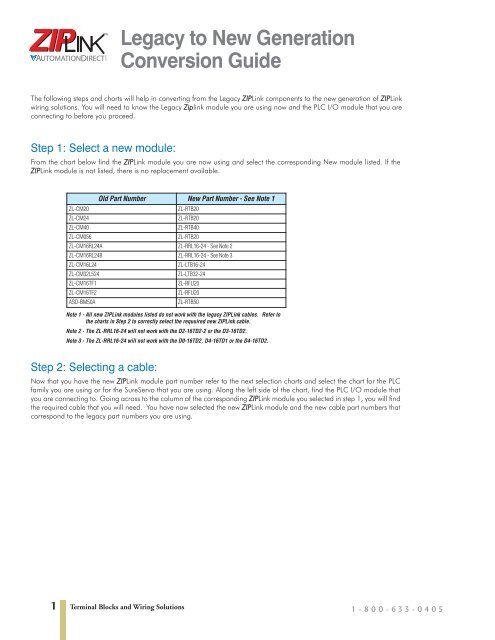
Legacy to New Generation<strong>Conversion</strong> <strong>Guide</strong>The following steps and charts will help in converting from the Legacy ZIPLink <strong>com</strong>ponents to the new generation of ZIPLinkwiring solutions. You will need to know the Legacy Ziplink module you are using now and the PLC I/O module that you areconnecting to before you proceed.Step 1: Select a new module:From the chart below find the ZIPLink module you are now using and select the corresponding New module listed. If theZIPLink module is not listed, there is no replacement available.ZL-CM20ZL-CM24ZL-CM40ZL-CM056Old Part Number New Part Number - See Note 1ZL-RTB20ZL-RTB20ZL-RTB40ZL-RTB20ZL-CM16RL24A ZL-RRL16-24 - See Note 2ZL-CM16RL24B ZL-RRL16-24 - See Note 3ZL-CM16L24ZL-CM32L524ZL-CM16TF1ZL-CM16TF2ASD-BM50AZL-LTB16-24ZL-LTB32-24ZL-RFU20ZL-RFU20ZL-RTB50Note 1 - All new ZIPLink modules listed do not work with the legacy ZIPLink cables. Refer tothe charts in Step 2 to correctly select the requuired new ZIPLink cable.Note 2 - The ZL-RRL16-24 will not work with the D2-16TD2-2 or the D3-16TD2.Note 3 - The ZL-RRL16-24 will not work with the D0-16TD2, D4-16TD1 or the D4-16TD2.Step 2: Selecting a cable:Now that you have the new ZIPLink module part number refer to the next selection charts and select the chart for the PLCfamily you are using or for the SureServo that you are using. Along the left side of the chart, find the PLC I/O module thatyou are connecting to. Going across to the column of the corresponding ZIPLink module you selected in step 1, you will findthe required cable that you will need. You have now selected the new ZIPLink module and the new cable part numbers thatcorrespond to the legacy part numbers you are using.1Terminal Blocks and Wiring Solutions 1-800-633-0405
Wiring System for CLICK PLCsStep 1Step 2Locate the CLICK CPU module or I/O module part number.Locate <strong>com</strong>patible connector module type.Step 3 Select the cable length by replacing the # symbol with: Blank = 0.5m, -1 = 1.0m, -2 = 2.0mZIPLink Wiring System Compatibility Matrix for CLICK PLCsStep 2: Connector Module Type Feedthrough Module Fuse Module Relay Modules Sensor Input ModuleZL-RTB20 ZL-RFU20 ZL-RRL16-24 ZL-LTB16-24Step 1: I/O unit Number of TerminalsStep 3: CablesCPU ModuleI/O ModuleC0-00DD1-D 20 ZL-C0-CBL20#C0-00DD2-D 20 ZL-C0-CBL20#C0-00DR-D 20 ZL-C0-CBL20#C0-00AR-D 20 ZL-C0-CBL20#InputsC0-08ND3 11 ZL-C0-CBL11#C0-08ND3-1 11 ZL-C0-CBL11#C0-08NA 11 ZL-C0-CBL11#C0-16ND3 20 ZL-C0-CBL20# ZL-C0-CBL20#OutputsC0-08TD1 11 ZL-C0-CBL11#C0-08TD2 11 ZL-C0-CBL11#C0-08TR 11 ZL-C0-CBL11#C0-08TA 11 ZL-C0-CBL11#C0-16TD1 20 ZL-C0-CBL20# ZL-C0-CBL20# ZL-C0-CBL20#C0-16TD2 20 ZL-C0-CBL20# ZL-C0-CBL20#C0-04TRS* 20 ZL-C0-CBL20#*Note: The CO-04TRS relay output is derated not to exceed 2A per point max. when used with the ZIPLink wiring systemZIPLink Connector Modules specifications begin on page 26-56ZIPLink Cables specifications begin on page 26-742 Terminal Blocks and Wiring Solutions1-800-633-0405
Wiring System for DL05/06 PLCsPLCOverviewDL05/06PLCStep 1 Locate the I/O Module part number.Step 2 Locate Connector Module Type. (Feedthrough Module, Fuse Module, etc...)Step 3 Select the cable length by replacing the # symbol with: Blank = 0.5m, -1 = 1m, -2 = 2m 11 Note: Cable part number denotes <strong>com</strong>patibility between Connector Module and I/O Modules.I/O ModuleStep 2: Connector Module Type FeedthroughModulesStep 1: I/O ModuleDL05/06 PLCs ZIPLink Wiring System Compatibility MatrixNumber ofTerminalsFuse ModulesRelay ModulesSensor InputModulesZL-RTB20 ZL-RFU20 ZL-RRL16-24 ZL-LTB16-24Step 3: CablesInputsPigtail CableD0-10ND3 13 ZL-D0-CBL13#D0-10ND3F 13 ZL-D0-CBL13#D0-16ND3 24 ZL-D0-CBL24#L ZL-D0-CBL24#L ZL-D0-CBL24#PF0-08NA-1 10 ZL-D0-CBL10#OutputsD0-10TD1 13 ZL-D0-CBL13#D0-16TD1 24 ZL-D0-CBL24# ZL-D0-CBL24# ZL-D0-CBL24# ZL-D0-CBL24#PD0-10TD2 13 ZL-D0-CBL13#D0-16TD2 24 ZL-D0-CBL24# ZL-D0-CBL24# ZL-D0-CBL24#PD0-08TR 10 ZL-D0-CBL10#F0-04TRS* 13 ZL-D0-CBL13#Combo In/OutD0-07CDR 10 ZL-D0-CBL10#D0-08CDD1 13 ZL-D0-CBL13#AnalogF0-04AD-1 8 ZL-D0-CBL8#F0-04AD-2 8 ZL-D0-CBL8#F0-08ADH-1 13 ZL-D0-CBL13#F0-08ADH-2 13 ZL-D0-CBL13#F0-04DAH-1 13 ZL-D0-CBL13#F0-08DAH-1 13 ZL-D0-CBL13#F0-04DAH-2 13 ZL-D0-CBL13#F0-08DAH-2 13 ZL-D0-CBL13#F0-2AD2DA-2 8 ZL-D0-CBL8#F0-4AD2DA-1 8 ZL-D0-CBL8#F0-4AD2DA-2 8 ZL-D0-CBL8#F0-04RTD**F0-04THM***Caution: The F0-04TRS relay outputs are derated not to exceed 2 Amps per point when used with the ZIPLink wiring system.**The F2-04RTD and F2-04THM modules are not supported by the ZIPLink wiring system. These modules require wire specific to thesignal type.ZIPLink Connector Modules specifications begin on page 26-56ZIPLink Cables specifications begin on page 26-74DL105PLCDL205PLCDL305PLCDL405PLCField I/OSoftwareC-moreHMIsOther HMIAC DrivesMotorsSteppers/ServosMotorControlsProximity SensorsPhotoSensorsLimitSwitchesEncodersCurrentSensorsPushbuttons/LightsProcessRelays/TimersComm.TB’s &WiringPowerCircuitProtectionEnclosuresAppendixPart Indexwww.automationdirect.<strong>com</strong>/ziplinks Terminal Blocks and Wiring Solutions 3
Step 1Locate the I/O module part number.Step 2Locate Connector Module Type. (Feedthrough Module, Fuse Module, etc...)Step 3 Select the cable length by replacing the # symbol with: Blank = 0.5m, -1 = 1.0m, -2 = 2.0m 11 Note: Cable part number denotes <strong>com</strong>patibility between Connector Module and I/O Modules.DL205 PLCs ZIPLink Wiring System Compatibility MatrixStep 2: Connector ModuleTypeFeedthrough Modules Fuse ModulesRelayModulesSensor Input ModulesI/O ModuleStep 1: I/OModuleNumber ofTerminalsWiring System for DL205 PLCsZL-RTB20 ZL-RTB40 ZL-RFU20 ZL-RFU40 ZL-RRL16-24 ZL-LTB16-24 ZL-LTB32-24Step 3: CablesInputsPigtailCableD2-08ND3 10 ZL-D2-CBL10#D2-16ND3-2 19 ZL-D2-CBL19# ZL-D2-CBL19# ZL-D2-CBL19#PD2-32ND3 40 ZL-D24-CBL40# ZL-D24-CBL40# ZL-D2-CBL40#PD2-32ND3-2 40 ZL-D24-CBL40# ZL-D24-CBL40# ZL-D2-CBL40#PD2-08NA-1 10 ZL-D2-CBL10#D2-08NA-2 10 ZL-D2-CBL10#D2-16NA 19 ZL-D2-CBL19# ZL-D2-CBL19#POutputsD2-04TD1* 10 ZL-D2-CBL10#D2-08TD1 10 ZL-D2-CBL10#D2-08TD2 10 ZL-D2-CBL10#D2-16TD1-2 19 ZL-D2-CBL19# ZL-D2-CBL19# ZL-D2-CBL19# ZL-D2-CBL19#PD2-16TD2-2 19 ZL-D2-CBL19# ZL-D2-CBL19# ZL-D2-CBL19#PD2-32TD1 40 ZL-D24-CBL40# ZL-D24-CBL40# ZL-D2-CBL40#PD2-32TD2 40 ZL-D24-CBL40# ZL-D24-CBL40# ZL-D2-CBL40#PD2-08TA 10 ZL-D2-CBL10#F2-08TA 10 ZL-D2-CBL10#D2-12TA 19 ZL-D2-CBL19# ZL-D2-CBL19# ZL-D2-CBL19#PD2-04TRS* 10 ZL-D2-CBL10#D2-08TR 10 ZL-D2-CBL10#F2-08TRS* 19 ZL-D2-CBL19# ZL-D2-CBL19#PF2-08TR** 10 ZL-D2-CBL10#D2-12TR 19 ZL-D2-CBL19# ZL-D2-CBL19# ZL-D2-CBL19#PCombo In/OutD2-08CDR 10 ZL-D2-CBL10#AnalogF2-04AD-1 10 ZL-D2-CBL10#F2-04AD-1L 10 ZL-D2-CBL10#F2-08AD-1 10 ZL-D2-CBL10#F2-04AD-2 10 ZL-D2-CBL10#F2-04AD-2L 10 ZL-D2-CBL10#F2-08AD-2 10 ZL-D2-CBL10#F2-02DA-1 10 ZL-D2-CBL10#F2-02DA-1L 10 ZL-D2-CBL10#F2-02DAS-1 10 ZL-D2-CBL10#F2-08DA-1 19 ZL-D2-CBL19# ZL-D2-CBL19#PF2-02DA-2 10 ZL-D2-CBL10#F2-02DA-2L 10 ZL-D2-CBL10#F2-02DAS-2 10 ZL-D2-CBL10#F2-08DA-2 10 ZL-D2-CBL10#F2-4AD2DA 10 ZL-D2-CBL10#F2-8AD4DA-1 19 ZL-D2-CBL19# ZL-D2-CBL19#PF2-8AD4DA-2 19 ZL-D2-CBL19# ZL-D2-CBL19#PF2-04RTD***F2-04THM****Caution: The D2-04TD1, D2-04TRS, and F2-08TRS outputs are derated not to exceed 2 Amps per point and 2 Amps per <strong>com</strong>mon when used with the ZIPLink wiring system.**The F2-08TR outputs are derated not to exceed 2 Amps per point and 4 Amps per <strong>com</strong>mon when used with the ZIPLink wiring system.***The F2-04RTD and F2-04THM modules are not supported by the ZIPLink wiring system. These modules require wire specific to the signal type.ZIPLink Connector Modules specifications begin on page 26-56ZIPLink Cables specifications begin on page 26-744 Terminal Blocks and Wiring Solutions1-800-633-0405
Wiring System for DL305 PLCsPLCOverviewDL05/06PLCStep 1 Locate the I/O module part number.Step 2 Locate Connector Module Type. (Feedthrough Module, Fuse Module, etc...)Step 3 Select the cable length by replacing the # symbol with: Blank = 0.5m, -1 = 1.0m, -2 = 2.0m 11 Note: Cable part number denotes <strong>com</strong>patibility between Connector Module and I/O Modules.I/O ModuleDL305 PLCs ZIPLink Wiring System Compatibility MatrixStep 2: Connector Module Type Feedthrough Modules Fuse Modules Relay Modules Sensor Input ModulesStep 1: I/O ModuleNumber ofTerminalsZL-RTB20 ZL-RFU20 ZL-RRL16-24 ZL-LTB16-24Step 3: CablesInputsD3-08ND2* 10D3-16ND2-1 18 ZL-D3-CBL18#D3-16ND2F 18 ZL-D3-CBL18#F3-16ND3F 18 ZL-D3-CBL18#D3-08NA-1* 10D3-08NA-2* 10D3-16NA 18 ZL-D3-CBL18#D3-08NE3* 10D3-16NE3 18 ZL-D3-CBL18# ZL-D3-CBL18#OutputsD3-04TD1* 10D3-08TD1* 10D3-08TD2* 10D3-16TD1-1 18 ZL-D3-CBL18# ZL-D3-CBL18# ZL-D3-CBL18#D3-16TD2 18 ZL-D3-CBL18# ZL-D3-CBL18#D3-04TAS* 10F3-08TAS-1 18 ZL-D3-CBL18#D3-08TA-1 18 ZL-D3-CBL18#D3-08TA-2* 10F3-16TA-2 18 ZL-D3-CBL18# ZL-D3-CBL18#D3-16TA-2 18 ZL-D3-CBL18# ZL-D3-CBL18#D3-08TR* 10D3-16TR** 18 ZL-D3-CBL18# ZL-D3-CBL18#F3-08TRS-1** 18 ZL-D3-CBL18#F3-08TRS-2** 18 ZL-D3-CBL18#AnalogF3-04ADS 18 ZL-D3-CBL18#F3-08AD-1 18 ZL-D3-CBL18#F3-16AD 18 ZL-D3-CBL18#F3-04DA-1 18 ZL-D3-CBL18#F3-04DAS 18 ZL-D3-CBL18#F3-08THM-J***F3-08THM-K****These I/O modules have non-removable terminal blocks which can be terminated using the ZL-CBL24-N cable and the ZL-RTB20 module of the ZIPLinkwiring system.**Caution: The D3-16TR, F3-08TRS-1 and F3-08TRS-2 relay outputs are derated not to exceed 2 Amps per point and 4 Amps per <strong>com</strong>mon when used with theZIPLink wiring system.***The F3-08THM-J and F3-08THM-K modules are not supported by the ZIPLink wiring system. These modules require wire specific to the signal type.<strong>ZIPLinks</strong> Connector Modules specifications begin on page 26-56<strong>ZIPLinks</strong> Cables specifications begin on page 26-74DL105PLCDL205PLCDL305PLCDL405PLCField I/OSoftwareC-moreHMIsOther HMIAC DrivesMotorsSteppers/ServosMotorControlsProximity SensorsPhotoSensorsLimitSwitchesEncodersCurrentSensorsPushbuttons/LightsProcessRelays/TimersComm.TB’s &WiringPowerCircuitProtectionEnclosuresAppendixPart Indexwww.automationdirect.<strong>com</strong>/ziplinks Terminal Blocks and Wiring Solutions 5
Wiring System for DL405 PLCsStep 1Locate the I/O module part number.Step 2Locate Connector Module Type. (Feedthrough Module, Fuse Module, etc...)Step 3 Select the cable length by replacing the # symbol with: Blank = 0.5m, -1 = 1.0m, -2 = 2.0m 11 Note: Cable part number denotes <strong>com</strong>patibility between Connector Module and I/O Modules.I/O ModuleStep 2: Connector ModuleTypeStep 1: I/O ModuleNumber ofTerminalsDL405 PLCs ZIPLink Wiring System Compatibility MatrixFeedthrough Modules Fuse ModulesRelayModulesSensor Input ModulesZL-RTB20 ZL-RTB40 ZL-RFU20 ZL-RFU40 ZL-RRL16-24 ZL-LTB16-24 ZL-LTB32-24Step 3: CablesInputsPigtail CableD4-08ND3S 20 ZL-D4-CBL20#D4-16ND2 20 ZL-D4-CBL20# ZL-D4-CBL20#D4-16ND2F 20 ZL-D4-CBL20# ZL-D4-CBL20#D4-32ND3-1 40 ZL-D24-CBL40# ZL-D24-CBL40# ZL-D24-CBL40#PD4-32ND3-2 40 ZL-D24-CBL40# ZL-D24-CBL40# ZL-D24-CBL40#PD4-64ND2* 40 ZL-D24-CBL40# ZL-D24-CBL40# ZL-D24-CBL40#PD4-08NA** 11D4-16NA 20 ZL-D4-CBL20#D4-16NA-1 20 ZL-D4-CBL20#D4-16NE3 20 ZL-D4-CBL20# ZL-D4-CBL20#F4-08NE3S 20 ZL-D4-CBL20#OutputsD4-08TD1** 11F4-08TD1S** 20D4-16TD1 20 ZL-D4-CBL20# ZL-D4-CBL20#D4-16TD2 20 ZL-D4-CBL20# ZL-D4-CBL20#D4-32TD1 40 ZL-D24-CBL40# ZL-D24-CBL40# ZL-D24-CBL40#PD4-32TD1-1 40 ZL-D24-CBL40# ZL-D24-CBL40# ZL-D24-CBL40#PD4-32TD2 40 ZL-D24-CBL40# ZL-D24-CBL40# ZL-D24-CBL40#PD4-64TD1* 40 ZL-D24-CBL40# ZL-D24-CBL40# ZL-D24-CBL40#PD4-08TA** 11D4-16TA 20 ZL-D4-CBL20# ZL-D4-CBL20#D4-08TR** 11F4-08TRS-1**** 20ZL-D4-CBL20#F4-08TRS-2**** 20ZL-D4-CBL20#D4-16TR*** 20 ZL-D4-CBL20# ZL-D4-CBL20#AnalogF4-04AD 20 ZL-D4-CBL20#F4-04ADS 20 ZL-D4-CBL20#F4-08AD 20 ZL-D4-CBL20#F4-16AD-1 20 ZL-D4-CBL20#F4-16AD-2 20 ZL-D4-CBL20#F4-04DA-1 20 ZL-D4-CBL20#F4-04DA-2 20 ZL-D4-CBL20#F4-08DA-1 20 ZL-D4-CBL20#F4-16DA-1 20 ZL-D4-CBL20#F4-08DA-2 20 ZL-D4-CBL20#F4-16DA-2 20 ZL-D4-CBL20#F4-04DAS-1 20 ZL-D4-CBL20#F4-04DAS-2 20 ZL-D4-CBL20#F4-08THM** 21F4-08THM-n** 21F4-08RTD** 20*The D4-64ND2 and D4-64TD1 modules have two 32-point connectors and require 2 ZIPLink cables and 2 ZIPLink connector modules.**These modules are not supported by the ZIPLink wiring system.***Caution: The D4-16TR relay outputs are derated not to exceed 2 Amps per point and 4 Amps per <strong>com</strong>mon when used with the ZIPLink wiring system.****The F4-08TRS-1 and F4-08TRS-2 are derated not to exceed 2 Amps per point and 2 Amps per <strong>com</strong>mon when used with the ZIPLink wiring system.<strong>ZIPLinks</strong> Connector Modules specifications begin on page 26-56<strong>ZIPLinks</strong> Cables specifications begin on page 26-746 Terminal Blocks and Wiring Solutions1-800-633-0405
Step 1Step 2Step 3Step 4Step 5Step1:SelectDriveGS1GS2DuraPulseSureServoSelect DriveSelect Network Type ProtocolSelect PLC TypeSelect PortCable TypeStep3: PLC CLICK DL05 DL06Step 4: Port Port 2 Port 2 Port 1 Port 2Step 2:NetworkType ProtocolRS485Modbus RTURS232Modbus RTURS485Modbus RTURS485Modbus RTURS232Modbus RTURS485Modbus RTUGS/DuraPulse/SureServo DriveWiring SolutionsDrive Communication Cable SelectionNote: If a PLC type or PLC port is not listed in the selection charts, it does not support modbus RTU.Step1:SelectDriveGS1GS2DuraPulseSureServoStep 5: Select Cable TypeNot Possible Not Possible Not Possible GS-485HD15-CBLNot Possible GS-RJ12-CBL-2 Not PossibleFA-15HD +GS-RJ12-CBL-2Not Possible Not Possible Not Possible GS-485HD15-CBLNot Possible Not Possible Not Possible GS-485HD15-CBLSVC-232RJ12-CBL-2 SVC-232RJ12-CBL-2 Not PossibleNot Possible Not Possible Not PossibleFA-15HD +SVC-232RJ12-CBL-2SVC-485HD15-CBL-2or(FA-15HD +SVC-485RJ12-CBL-2)Feedthrough Connector Module ZL-RTB50 Connecting CablesPart Number Description PriceZL-SVC-CBL50ZL-SVC-CBL50-1ZL-SVC-CBL50-2Step3: PLC D2-250-1 D2-260 D4-450Step 4: Port Port 2 Port 1 Port 2 Port 1Step 2: NetworkType ProtocolRS485Modbus RTURS232Modbus RTURS485Modbus RTURS485Modbus RTURS232Modbus RTURS485Modbus RTUStep 5:Cable TypeNot Possible Not Possible GS-485HD15-CBL-2 Not PossibleFA-15HD +GS-RJ12-CBL-2Not PossibleFA-15HD +GS-RJ12-CBL-2Shielded twisted pair cable with 50-pin connectors to connect any SureServo amplifier to a ZL-RTB50module, 28 AWG, 1.6 ft. (0.5m)Shielded twisted pair cable with 50-pin connectors to connect any SureServo amplifier to a ZL-RTB50module, 28 AWG, 3.3 ft. (1.0m)Shielded twisted pair cable with 50-pin connectors to connect any SureServo amplifier to a ZL-RTB50module, 28 AWG, 6.6 ft. (2.0m)FA-CABKIT +GS-RJ12-CBL-2Not Possible Not Possible GS-485HD15-CBL-2 Not PossibleNot Possible Not Possible GS-485HD15-CBL-2 Not PossibleFA-15HD +SVC-232RJ12-CBL-2 Not Possible FA-15HD +SVC-232RJ12-CBL-2Not Possible<strong>ZIPLinks</strong> Connector Modules specifications begin on page 26-56<strong>ZIPLinks</strong> Cables specifications begin on page 26-74Not PossibleSVC-485HD15-CBL-2or(FA-15HD +SVC-485RJ12-CBL-2)FA-CBLKIT +SVC-232RJ12-CBL-2Not PossiblePLCOverviewDL05/06PLCDL105PLCDL205PLCDL305PLCDL405PLCField I/OSoftwareC-moreHMIsOther HMIAC DrivesMotorsSteppers/ServosMotorControlsProximity SensorsPhotoSensorsLimitSwitchesEncodersCurrentSensorsPushbuttons/LightsProcessRelays/TimersComm.TB’s &WiringPowerCircuitProtectionEnclosuresAppendixPart Indexwww.automationdirect.<strong>com</strong>/ziplinks Terminal Blocks and Wiring Solutions 7