Operating & Maintenance Manual - FMC Technologies
Operating & Maintenance Manual - FMC Technologies
Operating & Maintenance Manual - FMC Technologies

Create successful ePaper yourself
Turn your PDF publications into a flip-book with our unique Google optimized e-Paper software.
<strong>Operating</strong> & <strong>Maintenance</strong> <strong>Manual</strong><br />
Weco ® Model ULT Plug Valves
Doc No: OMM50000121<br />
Rev: A Page 1 of 18<br />
OPERATING AND MAINTENANCE MANUAL, WECO MODEL ULT<br />
PLUG VALVES<br />
Rev ECN No. Date Reviewed By Approved By Status<br />
A 5014824 16-DEC-2005 Douglas, Don Soltau, James RELEASED<br />
Summary:<br />
<strong>Operating</strong>, maintenance and storage instructions – WECO ® Model ULT Plug Valves<br />
Subject to contractual terms and conditions to the contrary, this document and all the information contained herein are the confidential and exclusive<br />
property of <strong>FMC</strong> <strong>Technologies</strong>, and may not be reproduced, disclosed, or made public in any manner prior to express written authorization by <strong>FMC</strong>.
Table of Contents<br />
Doc No: OMM50000121<br />
Rev: A Page 2 of 18<br />
Section Title Page<br />
1.0 SAFETY INSTRUCTIONS ............................................................5<br />
2.0 OPERATING INSTRUCTIONS .....................................................5<br />
3.0 MAINTENANCE INSTRUCTIONS ................................................6<br />
3.1 REQUIRED TOOLS ......................................................................7<br />
3.2 DISASSEMBLY .............................................................................7<br />
3.3 ASSEMBLY...................................................................................8<br />
3.4 KITS AVAILABLE ..........................................................................9<br />
4.0 STORAGE INSTRUCTIONS.........................................................9<br />
5.0 APPENDIX – Assembly/Disassembly Graphics......................10<br />
6.0 TROUBLE SHOOTING GUIDE...................................................15<br />
Subject to contractual terms and conditions to the contrary, this document and all the information contained herein are the confidential and exclusive<br />
property of <strong>FMC</strong> <strong>Technologies</strong>, and may not be reproduced, disclosed, or made public in any manner prior to express written authorization by <strong>FMC</strong>.
List of Figures<br />
Doc No: OMM50000121<br />
Rev: A Page 3 of 18<br />
Figures Page<br />
Figure 1: Plug Valve Assembly*.......................................................................................6<br />
Figure 2: Install/Remove the Body Cap .........................................................................10<br />
Figure 3: Remove the Plug ............................................................................................10<br />
Figure 4: Install/Remove the Side Segments .................................................................11<br />
Figure 5: Install/Remove the Seal Segments .................................................................11<br />
Figure 6: Install/Remove the Wave Springs...................................................................12<br />
Figure 7: Seal Segment Inspection................................................................................12<br />
Figure 8: Position of Stem .............................................................................................13<br />
Figure 9: Align Milled Slot of Plug with Dimples .............................................................13<br />
Figure 10: Install Wave Springs .....................................................................................14<br />
Subject to contractual terms and conditions to the contrary, this document and all the information contained herein are the confidential and exclusive<br />
property of <strong>FMC</strong> <strong>Technologies</strong>, and may not be reproduced, disclosed, or made public in any manner prior to express written authorization by <strong>FMC</strong>.
WARNINGS<br />
Doc No: OMM50000121<br />
Rev: A Page 4 of 18<br />
<strong>FMC</strong> cannot anticipate all of the situations a user may encounter while installing and<br />
using <strong>FMC</strong> products. Therefore, the user of <strong>FMC</strong> products MUST know and follow all<br />
applicable industry specifications on the safe installation and use of these products.<br />
Refer to the <strong>FMC</strong> product catalogues, product brochures and installation, operating<br />
and maintenance manuals for additional product safety information or contact <strong>FMC</strong> at<br />
800-772-8582.<br />
WARNING: Failure to follow these warnings could result in serious injury or death!<br />
1. Do not mix or assemble components, parts or end<br />
connections with different pressure ratings. Mismatched<br />
parts may fail under pressure.<br />
2. Do not use or substitute non-<strong>FMC</strong> components or parts in<br />
<strong>FMC</strong> products and assemblies.<br />
3. Do not strike, tighten or loosen pressurized components or<br />
connections.<br />
4. Do not exceed the rated working pressure or temperature<br />
rating of the product.<br />
5. Complete and proper make-up of components and<br />
connections is required to attain rated working pressure.<br />
6. Do not use severely worn, eroded or corroded products.<br />
Contact <strong>FMC</strong> for more information on how to identify the<br />
limits of erosion and corrosion.<br />
7. Follow safe practices when using products in overhead<br />
applications. Products not properly secured could fall.<br />
8. Select only appropriate product and materials for the<br />
intended service:<br />
9. Do not expose standard service products to sour gas fluids.<br />
(Refer to NACE MR0175). Do not interchange sour gas<br />
with standard service components.<br />
Subject to contractual terms and conditions to the contrary, this document and all the information contained herein are the confidential and exclusive<br />
property of <strong>FMC</strong> <strong>Technologies</strong>, and may not be reproduced, disclosed, or made public in any manner prior to express written authorization by <strong>FMC</strong>.
10. Use appropriate safety precautions when working with<br />
ferrous products in below freezing temperatures. Freezing<br />
temperatures lower the impact strength of ferrous materials.<br />
11. Follow manufacturers instructions and Material Safety Data<br />
Sheet directions when using solvents<br />
12. Make certain that personnel and facilities are protected<br />
from residual hazardous fluids before disassembly of any<br />
product.<br />
13. If any leakage is detected from <strong>FMC</strong> products, remove<br />
them from service immediately to prevent potential damage<br />
and personal injury.<br />
1.0 SAFETY INSTRUCTIONS<br />
Doc No: OMM50000121<br />
Rev: A Page 5 of 18<br />
The applications of <strong>FMC</strong> products are in working environments where general<br />
personnel safety procedures and policies MUST be followed. Always use appropriate<br />
protective equipment in high pressure, extreme temperature or severe service<br />
applications.<br />
2.0 OPERATING INSTRUCTIONS<br />
WECO ® Model ULT plug valves are primarily used as isolation valves. The ULT plug<br />
valve is bi-directional; it can isolate flow from either direction.<br />
1. Prior to use, the valve should be inspected for proper<br />
operation. The valve should be free of contamination and<br />
the valve should actuate from open to close position freely.<br />
WARNING:<br />
Never look into the valve bore while the valve is in a flowline. Pressure<br />
and fluids could escape from the valve causing bodily injury.<br />
2. The valve should be thoroughly flushed with clean fresh<br />
water after each use and the bore of the valve should be<br />
sprayed with a light oil or comparable corrosion inhibitor.<br />
3. While the valve is in the open position, use the grease<br />
inserts located on both sides of the valve to pump CLIMAX<br />
plug valve grease into the valve until the grease is flushed<br />
out into the bore of the valve.<br />
Subject to contractual terms and conditions to the contrary, this document and all the information contained herein are the confidential and exclusive<br />
property of <strong>FMC</strong> <strong>Technologies</strong>, and may not be reproduced, disclosed, or made public in any manner prior to express written authorization by <strong>FMC</strong>.
4. To prevent leakage, malfunctions resulting from internal<br />
wear or seal degradation, the user must establish a<br />
preventative maintenance and inspection program. This<br />
program must include:<br />
1. Inspection of parts to detect loss of wall thickness that<br />
may result in decreased pressure capacity.<br />
2. Routine replacement of seals and inspection for proper<br />
operation.<br />
3.0 MAINTENANCE INSTRUCTIONS<br />
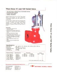
Figure 1: Plug Valve Assembly*<br />
Doc No: OMM50000121<br />
Rev: A Page 6 of 18<br />
* Note: Side segments, wave springs and grease plugs are not visible in this view.<br />
Subject to contractual terms and conditions to the contrary, this document and all the information contained herein are the confidential and exclusive<br />
property of <strong>FMC</strong> <strong>Technologies</strong>, and may not be reproduced, disclosed, or made public in any manner prior to express written authorization by <strong>FMC</strong>.
3.1 REQUIRED TOOLS<br />
Doc No: OMM50000121<br />
Rev: A Page 7 of 18<br />
Spanner wrench, sledge hammer, screw driver, adjustable wrench, solvent/rags,<br />
rubber mallet, grease, grease gun, Climax No. 1500, Anti-seize or equivalent, 400 grit<br />
or finer 3M WETORDRY Tri-M-Ite paper, and personal safety equipment. For the 4”<br />
ULT plug valve an optional <strong>FMC</strong> plug installation tool can be used.<br />
3.2 DISASSEMBLY<br />
1. Before getting started, bleed all pressure from the line.<br />
WARNING:<br />
Loosening the end connections or disassembly of the valve under<br />
pressure could result in the loss of pipe support, uncontrolled<br />
movement of the pipe section, valve components, or fluid spillage which<br />
may cause equipment damage and/or severe injury to operating<br />
personnel.<br />
2. If the bottom of the valve is not accessible, you will have to remove the valve from<br />
the line. You will need at least 2X the height of the valve as clearance on the<br />
bottom to service.<br />
3. Prior to assembly, cycle the valve to open to release any fluids that may be<br />
retained in the body. Leave the valve in the full open position.<br />
4. Remove the grease fittings using the adjustable wrench.<br />
5. If the valve is removed from the line, place the assembly on one side on a secure<br />
surface. Attach the spanner wrench to the body cap (see figure 2). Using the<br />
sledgehammer to drive the spanner wrench, loosen the body cap from the valve<br />
body taking special care not to damage the threads and o-ring seal groove.<br />
6. Place the valve assembly with the valve cavity facing up (see figure 3). Using a<br />
bar-type puller, remove the plug utilizing the tapped hole on the bottom of plug<br />
while reacting against the valve body. Pull the plug out of the valve cavity taking<br />
care not to damage the plug as this is a metal-to-metal sealing surface. An<br />
optional <strong>FMC</strong> plug removal tool can be used (4” valve only).<br />
7. Remove the side segments (see Figure 4) and then the seal segments (see<br />
Figure 5). If necessary, carefully pry the side segments away from the body using<br />
a screwdriver (Be careful not to scratch the valve cavity).<br />
8. Remove the booster springs from each seal segments (see figure 6).<br />
Note: Do not remove the plug by pushing on the stem. If the stem is<br />
removed, a separate procedure is required to re-install the stem and<br />
stem seals to prevent leakage.<br />
9. Remove and properly discard the old grease on the parts and inside the valve<br />
cavity.<br />
Subject to contractual terms and conditions to the contrary, this document and all the information contained herein are the confidential and exclusive<br />
property of <strong>FMC</strong> <strong>Technologies</strong>, and may not be reproduced, disclosed, or made public in any manner prior to express written authorization by <strong>FMC</strong>.
3.3 ASSEMBLY<br />
Doc No: OMM50000121<br />
Rev: A Page 8 of 18<br />
WARNING: Always use solvents in accordance with Material Safety Data Sheet.<br />
1. Check/verify parts against bill of materials; clean all parts and inspect for nicks,<br />
burrs or excessive wear.<br />
2. If the work is being performed with the valve out of line, position the body so that<br />
the assembly can be performed with the valve cavity facing upward. Preferably,<br />
the valve is to be placed on a table modified to allow the passage of the stem<br />
through the table top.<br />
3. Install the inner and outer s-seals onto the seal segments. Make sure that<br />
orientation is correct (after installation a single “o-ring bump” should face outward<br />
in each s-seal). Apply a thin film of Lubriplate to the outside diameter surfaces of<br />
the seal segments. Using your index finger remove the excess Lubriplate<br />
between the two s-seals. If too much Lubriplate is in between the s-seals,<br />
difficulty in the installation of the plug could occur later. Apply a liberal amount of<br />
plug valve grease to the ID of the seal segments. Insure that the ramp angle is<br />
covered. Carefully install the two seal segments into the valve cavity while<br />
aligning the locator pin holes with the locator pins in the valve cavity (see Figure<br />
5).<br />
4. Inspect the lead-in chamfer of the seal segments; this area should be free of<br />
nicks, chips and sharp edges (see figure 7). Apply a liberal amount of Lubriplate<br />
to the lead-in chamfer of the seal segments.<br />
5. Apply a liberal amount of plug valve grease to the side segments and install them<br />
into the valve cavity. It may be necessary to push the seals segments outward<br />
when installing the side segments (see figure 4).<br />
6. Check plug for nicks, scratches and sharp edges on the lead-in chamfer. Apply a<br />
liberal amount of grease to the OD of the plug and Lubriplate to the lead-in<br />
chamfer. Verify the stem is in the open position (The position of the tang of the<br />
stem should be perpendicular (vertical) to the fluid bore of the valve; see figure 8).<br />
Align the milled slot of the plug with the dimples of the seal segments (see figure<br />
9). Using an arbor press gently press the plug in. Verify that the plug has seated<br />
correctly by looking in the bore; the bore of the plug should be inline with the bore<br />
of the body. An optional <strong>FMC</strong> plug installation tool can be used (4” valve only).<br />
7. Drive all four booster springs in the slots formed by the outer diameter of the seal<br />
segments and the valve cavity using a hammer and a brass punch (see figure<br />
10). It is important that the brass punch is used in driving the last inch of the<br />
booster springs into the assembly to prevent scoring the valve cavity sealing area.<br />
8. Install the back-up rings and o-rings onto the body cap. Verify that the orientation<br />
is correct using the assembly drawing in figure 1. Apply anti-seize to the threads<br />
Subject to contractual terms and conditions to the contrary, this document and all the information contained herein are the confidential and exclusive<br />
property of <strong>FMC</strong> <strong>Technologies</strong>, and may not be reproduced, disclosed, or made public in any manner prior to express written authorization by <strong>FMC</strong>.
Doc No: OMM50000121<br />
Rev: A Page 9 of 18<br />
of the body cap and Lubriplate to the seals. Install the body cap on the assembly<br />
(see figure 2).<br />
3.4 KITS AVAILABLE<br />
There are two types of kits available for servicing the WECO ® Model ULT Plug Valve.<br />
• Repair Kit w/ Plug: This is the most commonly needed kit and consists of the<br />
parts recommended for rebuilding the valve. This kit includes the plug.<br />
• Repair Kit w/o Plug: This is the most commonly needed kit and consists of the<br />
parts recommended for rebuilding the valve. This kit includes the plug.<br />
Table 1: WECO ® Model ULT Plug Valve Kits – Standard Service & Sour Service<br />
Standard<br />
Kit w/ Plug<br />
Standard<br />
Kit w/o<br />
Plug<br />
Sour Gas<br />
Kit<br />
3” ULT100 3” ULT150<br />
3-1/16”<br />
ULT150<br />
3” ULT200 4” ULT100 4” ULT150<br />
Subject to contractual terms and conditions to the contrary, this document and all the information contained herein are the confidential and exclusive<br />
property of <strong>FMC</strong> <strong>Technologies</strong>, and may not be reproduced, disclosed, or made public in any manner prior to express written authorization by <strong>FMC</strong>.<br />
4-1/16”<br />
ULT150<br />
N/a 3265500 P528304 P519446 P518243 3268180 P531289<br />
N/a P510214 n/a n/a P519505 n/a n/a<br />
3266024 n/a n/a P525393 n/a n/a n/a<br />
4.0 STORAGE INSTRUCTIONS<br />
When not in use, the valve should be stored in an area that protects it from sun, rain,<br />
sand, and other debris. Before storing the valve, ensure that the operating fluids<br />
have been removed by flushing with water. After cleaning, fully drain all fluids from<br />
the valve and spray the valve with a water displacing lubricant such as a Teflon / oil<br />
mix. Spray inside both flow bores as far into the valve as possible. Also spray the<br />
threads of the union ends. With the valve in the open position, use the grease inserts<br />
to grease the valve until the grease is flushed out into the bore of the valve. During<br />
long-term storage keep the valve dry and painted to prevent corrosion.
5.0 APPENDIX – Assembly/Disassembly Graphics<br />
Figure 2: Install/Remove the Body Cap<br />
Figure 3: Remove the Plug<br />
Doc No: OMM50000121<br />
Rev: A Page 10 of 18<br />
Subject to contractual terms and conditions to the contrary, this document and all the information contained herein are the confidential and exclusive<br />
property of <strong>FMC</strong> <strong>Technologies</strong>, and may not be reproduced, disclosed, or made public in any manner prior to express written authorization by <strong>FMC</strong>.
Figure 4: Install/Remove the Side Segments<br />
Figure 5: Install/Remove the Seal Segments<br />
Doc No: OMM50000121<br />
Rev: A Page 11 of 18<br />
Subject to contractual terms and conditions to the contrary, this document and all the information contained herein are the confidential and exclusive<br />
property of <strong>FMC</strong> <strong>Technologies</strong>, and may not be reproduced, disclosed, or made public in any manner prior to express written authorization by <strong>FMC</strong>.
Figure 6: Install/Remove the Wave Springs<br />
Figure 7: Seal Segment Inspection<br />
Doc No: OMM50000121<br />
Rev: A Page 12 of 18<br />
Subject to contractual terms and conditions to the contrary, this document and all the information contained herein are the confidential and exclusive<br />
property of <strong>FMC</strong> <strong>Technologies</strong>, and may not be reproduced, disclosed, or made public in any manner prior to express written authorization by <strong>FMC</strong>.
Figure 8: Position of Stem<br />
Figure 9: Align Milled Slot of Plug with Dimples<br />
Doc No: OMM50000121<br />
Rev: A Page 13 of 18<br />
Subject to contractual terms and conditions to the contrary, this document and all the information contained herein are the confidential and exclusive<br />
property of <strong>FMC</strong> <strong>Technologies</strong>, and may not be reproduced, disclosed, or made public in any manner prior to express written authorization by <strong>FMC</strong>.
Figure 10: Install Wave Springs<br />
Doc No: OMM50000121<br />
Rev: A Page 14 of 18<br />
Subject to contractual terms and conditions to the contrary, this document and all the information contained herein are the confidential and exclusive<br />
property of <strong>FMC</strong> <strong>Technologies</strong>, and may not be reproduced, disclosed, or made public in any manner prior to express written authorization by <strong>FMC</strong>.
6.0 TROUBLE SHOOTING GUIDE<br />
Figure 11. Leak path diagram<br />
WARNING: Always remove pressure from line before Trouble Shooting.<br />
Doc No: OMM50000121<br />
Rev: A Page 15 of 18<br />
Problem Possible Cause Recommended Repair<br />
Leak at body cap.<br />
Figure 11, leak path<br />
“A”.<br />
Damage body cap o-ring. Incorrect<br />
installation of backup ring<br />
Dents and deep scratches in the<br />
body cavity or body cap seal area.<br />
Remove body cap. Replace body cap o-ring and<br />
backup ring. Verify the backup ring is installed with<br />
concave side toward the o-ring. The o-ring should be<br />
located in the groove furthest from the threads. Fully<br />
grease and pressure test the valve to full working<br />
pressure prior to returning to service.<br />
Disassemble valve. Inspect body cavity for scratches,<br />
dents or corrosion in the body cap sealing area.<br />
Repair minor scratches and corrosion with 400 grit<br />
WETORDRY. Deep dents or gouges may require the<br />
body to be replaced. Fully grease and pressure test<br />
the valve to full working pressure prior to returning to<br />
service.<br />
Subject to contractual terms and conditions to the contrary, this document and all the information contained herein are the confidential and exclusive<br />
property of <strong>FMC</strong> <strong>Technologies</strong>, and may not be reproduced, disclosed, or made public in any manner prior to express written authorization by <strong>FMC</strong>.
Doc No: OMM50000121<br />
Rev: A Page 16 of 18<br />
Problem Possible Cause Recommended Repair<br />
Leaking between seal<br />
segment and body.<br />
Figure 11, leak path<br />
“B”.<br />
Leak between seal<br />
segment and plug.<br />
Figure 11, leak path<br />
“C”<br />
Contamination or foreign debris<br />
between the seal segment and body.<br />
Damaged or aged seal segment face<br />
seal.<br />
Damaged seal segment seal area<br />
due to scratches, corrosion, or<br />
erosion.<br />
Damaged body seal segment sealing<br />
surface due to scratches, corrosion,<br />
or erosion.<br />
Contamination or foreign debris<br />
between the seal segment and plug.<br />
Damaged seal segment due to<br />
scratched, corrosion or erosion.<br />
Damaged plug sealing surface due<br />
to scratches, corrosion, erosion,<br />
chipped or damaged plating.<br />
Cycle opened and closed several valve times. Fully<br />
grease valve and cycle several more times.<br />
Dissemble valve. Replace seal segment face seal.<br />
Full grease and pressure test the valve to full working<br />
pressure prior to returning to service.<br />
Disassemble valve. Inspect seal segments for<br />
scratches, dents or corrosion in the body cap sealing<br />
area. Repair minor scratches and corrosion with 400<br />
grit WETORDRY. Deep dents or gouges may require<br />
the seal segments to be replaced. Fully grease and<br />
pressure test the valve to full working pressure prior to<br />
returning to service.<br />
Disassemble valve. Inspect body to seal segment for<br />
scratches, dents or corrosion in the body cap sealing<br />
area. Repair minor scratches and corrosion with 400<br />
grit WETORDRY. Deep dents or gouges may require<br />
the body to be replaced. Fully grease and pressure<br />
test the valve to full working pressure prior to returning<br />
to service.<br />
Cycle opened and closed several valve times. Fully<br />
grease valve and cycle several more times.<br />
Disassemble valve. Inspect seal segments for<br />
scratches, dents or corrosion in the body cap sealing<br />
area. Repair minor scratches and corrosion with 400<br />
grit WETORDRY. Deep dents or gouges may require<br />
the seal segments to be replaced. Fully grease and<br />
pressure test the valve to full working pressure prior to<br />
returning to service.<br />
Disassemble valve. Inspect plug for scratches, dents<br />
or corrosion in the sealing area. Repair minor<br />
scratches and corrosion with 400 grit WETORDRY.<br />
Deep dents or gouges may require the plug to be<br />
replaced. Fully grease and pressure test the valve to<br />
full working pressure prior to returning to service.<br />
Subject to contractual terms and conditions to the contrary, this document and all the information contained herein are the confidential and exclusive<br />
property of <strong>FMC</strong> <strong>Technologies</strong>, and may not be reproduced, disclosed, or made public in any manner prior to express written authorization by <strong>FMC</strong>.
Problem<br />
Leak between valve<br />
body and<br />
operator/actuator.<br />
Figure 11, leak path<br />
“D”<br />
Doc No: OMM50000121<br />
Rev: A Page 17 of 18<br />
Possible Cause Recommended Repair<br />
Hydraulic oil from the hydraulic<br />
operator (if applicable).<br />
Damaged stem or stem adapter orings<br />
or back-ups.<br />
Damaged or contaminated stem to<br />
stem adapter seal surfaces.<br />
Damaged or contaminated body to<br />
stem adapter seal surfaces.<br />
Check hydraulic inlet and outlet fitting for leaks.<br />
Remove operator/actuator and test for leaks. Replace<br />
actuator if leakage is found. Fully grease and pressure<br />
test the valve to full working pressure prior to returning<br />
to service.<br />
Disassemble operator/actuator. Disassemble valve.<br />
Inspect the stem and stem adapter o-rings and backups<br />
for damage. Replace any damages o-ring and<br />
back-ups. Fully grease and pressure test the valve to<br />
full working pressure prior to returning to service.<br />
Disassemble operator/actuator. Disassemble valve.<br />
Inspect the stem to stem adapter for scratches, dents<br />
or corrosion. Repair minor scratches and corrosion<br />
with 400 grit WETORDRY. Deep dents or gouges may<br />
require the stem or stem adapter to be replaced. Fully<br />
grease and pressure test the valve to full working<br />
pressure prior to returning to service.<br />
Disassemble operator/actuator. Disassemble valve.<br />
Inspect the stem adapter seal area for scratches, dents<br />
or corrosion. Repair minor scratches and corrosion<br />
with 400 grit WETORDRY. Deep dents or gouges may<br />
require the body to be replaced. Fully grease and<br />
pressure test the valve to full working pressure prior to<br />
returning to service.<br />
Subject to contractual terms and conditions to the contrary, this document and all the information contained herein are the confidential and exclusive<br />
property of <strong>FMC</strong> <strong>Technologies</strong>, and may not be reproduced, disclosed, or made public in any manner prior to express written authorization by <strong>FMC</strong>.
Doc No: OMM50000121<br />
Rev: A Page 18 of 18<br />
Problem Possible Cause Recommended Repair<br />
Leak at grease fitting.<br />
Figure 11, leak path<br />
“E”.<br />
Loose grease fitting. Tighten the grease fitting. Fully grease and pressure<br />
test the valve to full working pressure prior to<br />
Damaged or contaminated grease<br />
fitting.<br />
Damaged or contaminated grease<br />
fitting threads.<br />
Damaged body grease fitting<br />
threads.<br />
returning to service.<br />
Remove grease fitting and replace with a new<br />
grease fitting using Teflon tape on threads. Fully<br />
grease and pressure test the valve to full working<br />
pressure prior to returning to service.<br />
Remove grease fitting. Clean and inspect the<br />
threads. If the threads are intact , replace the Teflon<br />
tape on the grease fittings and install in the body. If<br />
the threads are damaged, replace the grease fitting<br />
with a new grease fitting using Teflon tape on the<br />
threads. Fully grease and pressure test the valve to<br />
full working pressure prior to returning to service.<br />
Remove the grease fitting. Clean and inspect body<br />
threads. If the threads are intact, replace the Teflon<br />
tape on the grease fitting and install in the body. If<br />
threads are damaged replace the body. Fully<br />
grease and pressure test the valve to full working<br />
pressure prior to returning to service.<br />
Subject to contractual terms and conditions to the contrary, this document and all the information contained herein are the confidential and exclusive<br />
property of <strong>FMC</strong> <strong>Technologies</strong>, and may not be reproduced, disclosed, or made public in any manner prior to express written authorization by <strong>FMC</strong>.
<strong>FMC</strong> <strong>Technologies</strong>, Inc<br />
1803 Gears Road<br />
Houston, Texas 77067<br />
Tel 281.260.2121<br />
Fax 281.260.2122<br />
Manufacturing<br />
2825 West Washington<br />
Stephenville, Texas 76401<br />
Tel 1.800.772.8582 (U.S.)<br />
Tel 254.968.2181<br />
Fax 254.968.5709<br />
Aberdeen, Scotland<br />
Tel (44) 1224.898.555<br />
Fax (44) 1224.249.460<br />
Dubai, United Arab Emirates<br />
Tel (00) 971 4 883.0303<br />
Fax (00) 971 4 883.0404<br />
Las Morochas, Venezuela<br />
Tel (58) 265.631.5284<br />
Fax (58) 265.631.5284<br />
Macae, RJ, Brazil<br />
Tel (55) 22.2773.0707<br />
Fax (55) 22.2773.0708<br />
Singapore<br />
Tel (65) 6.316.1908<br />
Fax (65) 6.316.2605<br />
Oklahoma City, Oklahoma<br />
Tel 405.787.6301<br />
Fax 405.787.6090<br />
Rock Springs, Wyoming<br />
Tel 307.382.4244<br />
Fax 307.382.4454<br />
North Texas<br />
Tel 940.328.0800<br />
Fax 940.328.0803<br />
Alice, Texas<br />
Tel 361.668.0886<br />
Fax 361.668.0905<br />
Farmington, New Mexico<br />
Tel 505.327.0634<br />
Fax 505.327.0641<br />
Grand Junction, Colorado<br />
Tel 970.245.1553<br />
Fax 970.245.6066<br />
Lafayette, Louisiana<br />
Tel 337.837.0700<br />
Fax 337.839.2235<br />
Longview, Texas<br />
Tel 903.757.4180<br />
Fax 903.757.2514<br />
Odessa, Texas<br />
Tel 432.552.9150<br />
Fax 432.552.9151<br />
Villahermosa, Mexico<br />
Tel (52) 993.310.4870<br />
Fax (52) 993.350.1661