Technical Specification - MK Electric
Technical Specification - MK Electric
Technical Specification - MK Electric

You also want an ePaper? Increase the reach of your titles
YUMPU automatically turns print PDFs into web optimized ePapers that Google loves.
technical hotline +44 (0)1268 563720 white | wiring devices<br />
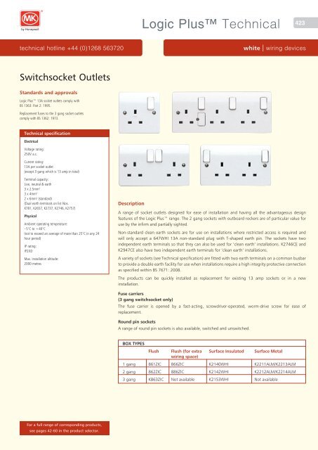
Switchsocket Outlets<br />
Standards and approvals<br />
Logic Plus 13A socket outlets comply with<br />
BS 1363: Part 2: 1995.<br />
Replacement fuses to the 3 gang socket outlets<br />
comply with BS 1362: 1973.<br />
<strong>Technical</strong> specification<br />
<strong>Electric</strong>al<br />
Voltage rating:<br />
250V a.c.<br />
Current rating:<br />
13A per socket outlet<br />
(except 3 gang which is 13 amp in total)<br />
Terminal capacity:<br />
Live, neutral & earth<br />
3 x 2.5mm 2<br />
3 x 4mm 2<br />
2 x 6mm 2 (standard)<br />
(Dual earth terminals on list Nos.<br />
K781, K2657, K2737, K2746, K2757)<br />
Physical<br />
Ambient operating temperature:<br />
–5°C to +40°C<br />
(not to exceed an average of more than 25°C in any 24<br />
hour period)<br />
IP rating:<br />
IP2XD<br />
Max. installation altitude:<br />
2000 metres<br />
For a full range of corresponding products,<br />
see pages 42-60 in the product selector.<br />
Description<br />
Logic Plus <strong>Technical</strong><br />
423<br />
A range of socket outlets designed for ease of installation and having all the advantageous design<br />
features of the Logic Plus range. The 2 gang sockets with outboard rockers are of particular value for<br />
use by the infirm and partially sighted.<br />
Non-standard clean earth sockets are for use on installations where restricted access is required and<br />
will only accept a 647WHI 13A non-standard plug with T-shaped earth pin. The sockets have two<br />
independent earth terminals so that they can also be used for ‘clean earth’ installations. K2746CE and<br />
K2947CE also have two independent earth terminals for ‘clean earth’ installations.<br />
A variety of sockets (see <strong>Technical</strong> specification) are fitted with two earth terminals on a common busbar<br />
to provide a double earth facility for use when installations require a high integrity protective connection<br />
as specified within BS 7671: 2008.<br />
The products can be quickly installed as replacement for existing 13 amp sockets or in a new<br />
installation.<br />
Fuse carriers<br />
(3 gang switchsocket only)<br />
The fuse carrier is opened by a fast-acting, screwdriver-operated, worm-drive screw for ease of<br />
replacement.<br />
Round pin sockets<br />
A range of round pin sockets is also available, switched and unswitched.<br />
BOX TYPES<br />
Flush Flush (for extra Surface Insulated Surface Metal<br />
wiring space)<br />
1 gang 861ZIC 866ZIC K2140WHI K2211ALM/K2213ALM<br />
2 gang 862ZIC 886ZIC K2142WHI K2212ALM/K2214ALM<br />
3 gang K863ZIC Not available K2153WHI Not available
424 Logic Plus <strong>Technical</strong><br />
wiring devices | white www.mkelectric.co.uk<br />
Switchsocket Outlets<br />
Features<br />
● Moulded ‘on’ indicator flash on switches<br />
will not rub off – totally safe<br />
● Optional neon indicators in the switch<br />
rockers with 175° visibility in the horizontal<br />
and vertical planes<br />
● 3 pin operated safety shutter<br />
● Printed terminal markings on grey rear<br />
mouldings for clearer identification<br />
● Top access, angled terminals make wiring<br />
easier and quicker<br />
● 3mm minimum switch contact gap<br />
● Double pole switching<br />
● Choice of inboard or outboard positioned<br />
rockers<br />
Installation<br />
Logic Plus socket outlets can be wall or bench<br />
mounted. Do not mount or use as a trailing<br />
socket or where they may be subject to excessive<br />
moisture or dampness.<br />
1 gang switchsocket – view from rear<br />
Top-facing, angled, backed-out terminals make<br />
wiring easier and quicker.<br />
Cable management<br />
Logic Plus socket outlets can be mounted in a<br />
variety of <strong>MK</strong> trunking systems.<br />
● Additional electrical safety from neutral<br />
‘make first’, ‘break last’ feature<br />
● Switch contacts with silver contacts on<br />
both surfaces for good continuity<br />
● Only one size of screwdriver required for<br />
installation<br />
● Selection of products incorporating dual<br />
earth terminals for high integrity earthing<br />
● Backed out and captive terminal screws<br />
● ‘Clean earth’ sockets available<br />
● Non-standard ‘clean earth’ sockets<br />
available<br />
● Selected sockets available in graphite finish<br />
to assist with Part M compliance<br />
86<br />
86<br />
86<br />
Dimensions (mm)<br />
1 gang<br />
2 gang<br />
3 gang<br />
86 30<br />
60.3 17<br />
146 30<br />
120.6 17<br />
fuse<br />
206 32<br />
86<br />
180.9 19<br />
146 30<br />
120.6 17
Logic Plus <strong>Technical</strong><br />
technical hotline +44 (0)1268 563720 white | wiring devices<br />
Sentrysocket RCD Protected Switchsocket Outlet<br />
Compliance with EC Directives,<br />
Standards and approvals<br />
Sentrysockets comply with the following<br />
EC Directives and are CE marked:<br />
Low Voltage Directive<br />
Electromagnetic Compatibility Directive (89/336/EEC)<br />
Sentrysocket RCD Single Sockets also comply with<br />
the requirements of the following standards:<br />
BS 7288: 1990<br />
BS EN 50082-1: 1998<br />
Sentrysocket RCD Double Sockets comply with BS EN 61543: 1996<br />
and BS EN 55014-1<br />
<strong>Technical</strong> specification<br />
<strong>Electric</strong>al<br />
Rated Voltage:<br />
240V a.c., 50 or 60Hz<br />
Current rating:<br />
13A resistive<br />
Rated tripping current<br />
30mA and 10mA versions<br />
Terminal capacity:<br />
3 x 4mm 2 for 1 gang<br />
2 x 4mm 2 for 2 gang<br />
Physical<br />
Ambient operating temperature:<br />
–5°C to +40°C<br />
IP rating:<br />
IP2XD<br />
Max. installation altitude:<br />
2000 metres<br />
Sentrysockets are only suitable for use in TN-S system<br />
where the Supply Neutral Connection is connected to the<br />
Supply Earth.<br />
They are not suitable for connection across two lines of a<br />
127V line to Neutral Voltage System.<br />
Installation<br />
Logic Plus RCD protected switch socket outlets<br />
can be wall or bench mounted. Do not mount<br />
or use as a trailing socket or where they may be<br />
subject to excessive moisture or dampness.<br />
Flush mounting steel wall box<br />
It should be noted that some of the conduit<br />
entries may be restricted, depending upon their<br />
positions and the depth of box used.<br />
Cable management<br />
Sentrysockets can be mounted in a variety of <strong>MK</strong><br />
trunking systems.<br />
Description<br />
425<br />
Sentrysocket provides a high level of protection against electrocution and gives further protection when<br />
used with appliances vulnerable to insulation damage, particularly when they are in damp environments<br />
or outdoors. Sentrysocket is not suitable for mounting in damp environments or outdoors.<br />
Sentrysocket, incorporating an RCD, is part of a complete range of fixed and portable wiring devices and<br />
circuit protection devices suitable for use in domestic, commercial and industrial applications.<br />
Active control circuits<br />
Incorporate a ‘Re-set’ mechanism and are mains failure sensitive, ie they will function under all the<br />
normal conditions expected of an RCD, but will also trip in the event of a power cut or a sudden,<br />
dramatic reduction in mains voltage. This makes them ideal for use where it would be hazardous for<br />
equipment to suddenly energise after return of mains power, such as use with rotating machinery and<br />
heat developing apparatus.<br />
Passive control circuits<br />
Incorporate a ‘Stay-set’ mechanism and is mains failure proof, ie it will function under all the normal<br />
conditions expected of an RCD and will not trip in the event of a power cut. This makes it suitable for use<br />
with freezers or in inaccessible or unmanned locations.<br />
Features<br />
● Suitable for most residential, commercial<br />
and light industrial applications<br />
● Active and passive control circuit<br />
applications<br />
● Comply fully with current Wiring<br />
Regulations<br />
● Double pole switching<br />
Dimensions (mm)<br />
86<br />
Single socket<br />
sentrysocket<br />
rcd protected<br />
● Flexible and versatile in use<br />
● Ideal for use with equipment subject to wet<br />
weather or high humidity<br />
● Part of a complete range of <strong>MK</strong> circuit<br />
protection devices<br />
● They are a.c. and pulsating DC sensitive for<br />
residual current<br />
146 6 24<br />
146 3.3 26.5<br />
T<br />
test before use<br />
press button - T<br />
white<br />
off<br />
(tripped)<br />
red<br />
on on<br />
active control<br />
device trips with<br />
loss of mains<br />
10mA tripping current<br />
120.6 14<br />
86<br />
Double socket<br />
sentrysocket<br />
rcd protected<br />
T<br />
R<br />
Flag below Reset (R) button.<br />
Red : ON Black: OFF<br />
ALWAYS TEST BEFORE USE<br />
Press Test (T) button, Red flag should<br />
disappear. If it does not, do not use.<br />
Press Reset (R) after testing.<br />
120.6 9
426 Logic Plus <strong>Technical</strong><br />
wiring devices | white www.mkelectric.co.uk<br />
Sentrysocket<br />
Installation<br />
Flush mounting steel wall box<br />
It should be noted that some of the conduit entries may be restricted,<br />
depending upon their positions and the depth of box used.<br />
Socket Testing:<br />
Single Socket Testing<br />
After installation, turn the mains electricity supply on.<br />
To test that the Sentrysocket is functioning correctly:<br />
1. Ensure that no appliance is connected to the Sentrysocket. Switch<br />
Sentrysocket on: The switch should remain closed and the red flag will<br />
appear in the window. If the switch fails to remain closed, check that the<br />
Supply L and N connections are not reversed or the Supply N connection<br />
is not open circuit. If the Sentrysocket is correctly connected and still trips<br />
after being switched on, the Sentrysocket is faulty and should not be<br />
used<br />
2. If the Sentrysocket stays on, press the test button: The switch will<br />
open and the white flag will appear In the window. If the Sentrysocket<br />
does not trip and there is mains voltage present at the socket outlet,<br />
Sentrysocket is faulty and should not be used.<br />
3. Switch Sentrysocket on: Connect an RCD tester and ensure that the<br />
Sentrysocket trips within the specified time:<br />
≤ 200 ms AT RATED TRIP CURRENT<br />
≤ 40 ms AT 5 x RATED TRIP CURRENT<br />
If the Sentrysocket does not trip within the specified times then the<br />
product is faulty and should not be used (If more than one RCD is in<br />
series then there is no guarantee as to which device will trip first).<br />
4. Reset all tripped RCD’s including the Sentrysocket.<br />
5. Switch off the mains supply switch disconnector. On mains failure,<br />
a Sentrysocket with Active Control Circuit will trip, whilst a Sentrysocket<br />
with Passive Control Circuit will not trip. If the Active Control device<br />
does not trip, it is faulty and should not be used – see note below. If<br />
no faults have been found then installation testing has been completed<br />
successfully.<br />
Note: If a fault is identified at any stage of installation testing procedure<br />
do not use Sentrysocket, and contact your local electrician, or your local<br />
<strong>MK</strong> stockist.<br />
Double Socket Testing<br />
After installation, turn the mains electricity supply on.<br />
To test that the Sentrysocket is functioning correctly follow the steps<br />
1 to 4 below:<br />
1. Ensure that no appliance is connected to the Sentrysocket.<br />
2. Reset – Press the button marked R (for Reset) – the contact status<br />
indicator should show red, indicating that the socket outlets are now live<br />
(if the switches are in the ON positions).<br />
3. Test – Press the TEST button marked T (for Test), the product should trip<br />
with the contact status indicator showing black. In this state the socket<br />
outlets are disconnected from the supply.<br />
4. Reset – Press the button marked R again, the contact status indicator<br />
should show red.<br />
5. Connect an RCD Tester to either socket outlet and ensure that the<br />
Sentrysocket trips with the specified times below:<br />
≤ 200 ms AT RATED TRIP CURRENT<br />
≤ 40 ms AT 5 x RATED TRIP CURRENT<br />
6. Reset the Sentrysocket as in step 2 above.<br />
7. Switch off the Mains Supply Switch Disconnector.<br />
8. A Sentrysocket with Active Control Circuit should trip while a Sentrysocket<br />
with Passive Control Circuit should not trip.<br />
If all the operations in steps 2 to 8 above give correct results, the Sentrysocket<br />
RCD socket outlet is safe to use.<br />
If the procedures in steps 2 to 8 above are not completed correctly,<br />
do not use the Sentrysocket product and seek professional advice<br />
or contact the <strong>MK</strong> <strong>Technical</strong> Sales and Service department on<br />
+44 (0)1268 563720.
technical hotline +44 (0)1268 563720 white | wiring devices<br />
Filtered Switchsocket Outlets<br />
Standards and approvals<br />
Logic Plus Filtered Switch Socket Outlets<br />
comply with BS 5733: 2010.<br />
<strong>Technical</strong> specification<br />
<strong>Electric</strong>al<br />
Current rating:<br />
13A maximum total for 2 sockets<br />
Voltage rating:<br />
250V a.c. 50Hz<br />
Earth leakage:<br />
0.5 mA<br />
Suppression:<br />
150 kHz – 30 MHz (transients)<br />
Maximum energy absorption:<br />
140 Joules L – N<br />
140 Joules L – E<br />
Terminal capacity:<br />
K1826 and K1816, 2 x 6mm 2<br />
3 x 4mm 2 , 3 x 2.5mm 2 , 3 x 1.5mm 2<br />
Physical<br />
Operating temperature:<br />
–5°C to +40°C (not to exceed an average of more than<br />
25°C in any 24 hour period)<br />
Thermal overload:<br />
The K1826 filter socket incorporates a thermal overload<br />
device in the RFI filter section. Overload current causes<br />
temperature rise, resulting in automatic ‘trip out’. The<br />
overload device will re-set as the temperature falls.<br />
IP rating:<br />
IP2XD<br />
Max. installation altitude:<br />
2000 metres<br />
Cable management<br />
Logic Plus socket outlets can be mounted in a<br />
variety of <strong>MK</strong> trunking systems.<br />
Dimensions (mm)<br />
86<br />
146 30<br />
120.6 17<br />
Description<br />
Logic Plus <strong>Technical</strong><br />
427<br />
A range of sockets in the Logic Plus style, designed to combat interference to or data losses on sensitive<br />
electrical products and systems due to mains borne voltage spikes and RFI.<br />
Such systems include:<br />
● Computer or microprocessor based equipment<br />
● Telecommunications systems<br />
● Electronic measurement equipment<br />
● Cash registers<br />
● Audio visual and hi-fi equipment<br />
These products can be quickly installed as replacements for existing twin 13 amp sockets or in a new<br />
installation.<br />
Two earth terminals on each product provide a double earth facility for use when installations require a<br />
high integrity protective connection as specified within BS 7671: 2008.<br />
Filter cassettes<br />
Filter cassettes are supplied with sockets and have an LED which shows green under normal conditions<br />
but will turn red or extinguish when a replacement cassette (K1800) is required. An alarm will also beep<br />
at 5 second intervals to indicate replacement necessity. It can be de-activated if required.<br />
Features<br />
● Moulded ‘on’ indicator flash on switches<br />
will not rub off – totally safe<br />
● 3 pin operated safety shutter<br />
● Printed terminal markings on grey rear<br />
mouldings for clearer identification<br />
● Reduces risk of damage to equipment and<br />
down time<br />
● Reduces risk of data loss<br />
● 2 way filtering – into appliance and back<br />
into mains supply<br />
● Double pole switches<br />
● Dual earth terminals for high integrity<br />
earthing<br />
● Clearly visible LED on filter cassette,<br />
changes from green to red when<br />
replacement required<br />
● Simple replacement of cassettes<br />
● 10 year guarantee (except filter cassette)<br />
● 3mm minimum switch contact gap<br />
● Backed out and captive terminal screws
428 Logic Plus <strong>Technical</strong><br />
wiring devices | white www.mkelectric.co.uk<br />
Filtered Switchsocket Outlets<br />
Product features<br />
Audible warning<br />
Ensure that the connecting pins protruding from the connector bottom of the<br />
replacement Filter Replacement<br />
Cassette are not damaged or bent before installation.<br />
If in doubt, contact filter cassette <strong>MK</strong> <strong>Technical</strong> Sales Service Department on<br />
+44 (0)1268 563720.<br />
Locking screw<br />
1. The <strong>MK</strong> Filtered Switchsocket, in common with many other filters<br />
uses Voltage Dependant Resistors for spike suppression purposes. The<br />
performance of these devices will eventually degrade with use to a level<br />
where they will no longer provide adequate protection.<br />
When this occurs the spike filer performance of the <strong>MK</strong> Filtered<br />
Switchsocket outlet can be restored by replacing the filter cassette.<br />
When the filter cassette needs replacing, the green indicator on the<br />
Replacement Filer Cassette will glow red or go out, an audible beep every<br />
five seconds may also be heard.<br />
Note: As with all filters, these Filter Sockets will reduce the magnitude of<br />
RFI and spikes and consequently their ability to interfere with connected<br />
equipment. They will not completely remove the interference from<br />
the supply.<br />
Figure 1<br />
Replacement Audible warning<br />
filter connector cassette<br />
Installation<br />
Filter indicator<br />
Locking screw<br />
Replaceable Spike Filter Cassette<br />
Note: To ensure a safe installation;<br />
Filter indicator<br />
Audible warning<br />
connector<br />
● this product should be installed by a competent person.<br />
● it is important that all connections are made as instructed.<br />
Filter indicator<br />
1. The filter cassette can be removed and replaced without switching off the<br />
mains or removing any plugs from the filter socket.<br />
2. Remove the filter cassette by turning the jacking screw anti-clockwise<br />
to partially eject it (see Figure 2), and then gently pulling the cassette<br />
upwards, (see Figure 2a).<br />
3. Only fit the <strong>MK</strong> Replacement Filter Cassette (K1800WHI).<br />
Unpack the new filer cassette and check that the pins along the bottom<br />
edge are not bent or broken. If these pins are damaged, do not fit the<br />
replacement cassette. The audible sound indicating that the filter cassette<br />
needs replacing, is optional. It may be prevented by removing the small<br />
connector on the two end pins, (see Figure 2b), before fitting it into<br />
the socket.<br />
Figure 2<br />
4. Fit the new filter cassette by carefully sliding it into the aperture and<br />
gently pushing it down while turning the screw clockwise until the filter<br />
cassette is flush with the surface. Do not turn the screw any further as<br />
this will cause distortion of the plastic mouldings.<br />
Product and packaging can safely be disposed of via standard refuse<br />
facilities at the end of its useful life.<br />
Figure 2a<br />
Figure 2b<br />
Audible warning<br />
connector
technical hotline +44 (0)1268 563720 white | wiring devices<br />
Round Pin Socket Outlets<br />
Standards and approvals<br />
Round pin socket outlets comply with BS 546: 1950.<br />
<strong>Technical</strong> specification<br />
<strong>Electric</strong>al<br />
Voltage rating:<br />
250V a.c.<br />
Terminal capacities:<br />
2 amp sockets (K770):<br />
7 x 1mm 2<br />
4 x 1.5mm 2<br />
2 x 2.5mm 2<br />
1 x 4mm 2<br />
5 amp sockets (K771, K2891):<br />
3 x 2.5mm 2<br />
2 x 4mm 2<br />
2 x 6mm 2 (stranded)<br />
15 amp sockets (K772, K2893, K2493):<br />
3 x 2.5mm 2<br />
3 x 4mm 2<br />
2 x 6mm 2 (stranded)<br />
Physical<br />
Ambient operating temperature:<br />
–5°C to +40°C<br />
(not to exceed an average of more than 25°C in any 24<br />
hour period)<br />
IP rating:<br />
IP2XD<br />
Max. installation altitude:<br />
2000 metres<br />
Installation<br />
Logic Plus socket outlets can be wall or bench<br />
mounted – do not mount or use as a trailing<br />
socket or where they may be subjected to<br />
excessive moisture or dampness.<br />
Cable management<br />
Logic Plus socket outlets can be mounted in a<br />
variety of <strong>MK</strong> trunking systems.<br />
Description<br />
Logic Plus <strong>Technical</strong><br />
429<br />
A range of round pin socket outlets designed for ease of installation and having all the advantages<br />
and design features of the round pin Logic Plus range. These products can be quickly installed as<br />
replace ments for existing socket outlets or in new installations.<br />
Features<br />
● Top access terminals make wiring easier<br />
and quicker<br />
● Integral ON indicator on switches will not<br />
rub off – totally safe<br />
● Optional neon indicator on 15A switched<br />
socket rockers with 175° visibility in the<br />
horizontal and vertical planes<br />
● 3mm minimum switch contact gap<br />
● Double pole switching<br />
● Terminal screws backed out<br />
Dimensions (mm)<br />
86<br />
BOX TYPES<br />
86<br />
60.2<br />
Depth<br />
2 Amp sockets: 12mm<br />
5 Amp sockets: 21mm<br />
15 Amp sockets: 23mm<br />
● Additional electrical safety from neutral<br />
“make first”, “break last” feature on<br />
switched sockets<br />
● Switch contacts with silver contact points<br />
on both surfaces for good continuity<br />
● 5A and 15A sockets contain a 3 pin<br />
operated safety shutter<br />
● Printed terminal markings on grey rear<br />
mouldings for clearer identification<br />
● 2A socket shuttered<br />
Flush for extra<br />
Flush wiring space Surface Insulated Surface Metal<br />
5A and 15A 861ZIC 866ZIC K2140WHI K2211ALM<br />
K2213ALM<br />
2A 3995ZIC 861ZIC K2140WHI K2211ALM<br />
866ZIC K2213ALM
430 Logic Plus <strong>Technical</strong><br />
wiring devices | white www.mkelectric.co.uk<br />
Non UK Socket Outlets<br />
Standards and approvals<br />
15A American sockets comply with SASO 2203: 2003<br />
16A 2P+E German sockets comply with IEC 60884-1: 2006<br />
<strong>Technical</strong> specification<br />
<strong>Electric</strong>al<br />
15A American Socket<br />
Voltage rating:<br />
127V a.c.<br />
Current rating:<br />
15A<br />
Terminal capacity:<br />
Live, neutral & earth<br />
3 x 2.5mm 2<br />
2 x 4mm 2<br />
1 x 6mm 2 (stranded)<br />
Max. installation altitude:<br />
2000 metres<br />
16A 2P+E German Socket<br />
Voltage rating:<br />
250V a.c.<br />
Current rating:<br />
16A<br />
Terminal capacity:<br />
Live, neutral & earth<br />
4 x 1.5mm 2<br />
2 x 2.5mm 2<br />
1 x 4mm 2<br />
Physical<br />
Ambient operating temperature:<br />
–5°C to +40°C<br />
(not to exceed an average of more than 25°C in any 24<br />
hour period)<br />
IP rating:<br />
IP2XD<br />
Max. installation altitude:<br />
2000 metres<br />
15A AMERICAN<br />
86<br />
86<br />
BOX TYPES<br />
86<br />
60.3<br />
86<br />
60.3<br />
86<br />
Flush Flush (for extra Surface<br />
wiring space)<br />
86<br />
146 9<br />
120.6 15<br />
1 gang 861ZIC 866ZIC K2140WHI<br />
2 gang 862ZIC 886ZIC K2142WHI<br />
16A 2P+E GERMAN<br />
146<br />
120.6<br />
9<br />
BOX TYPES<br />
30<br />
All dimensions<br />
in mm<br />
Flush Surface<br />
1 gang 866 ZIC K2031 WHI<br />
2 gang 886 ZIC K2172 WHI<br />
Note:<br />
16A 2P+E German<br />
Outlet: These<br />
products are NOT<br />
suitable for 25mm<br />
deep boxes.<br />
All dimensions<br />
in mm
technical hotline +44 (0)1268 563720 white | wiring devices<br />
Three Pole Fan Isolators<br />
Standards and approvals<br />
Comply with BS EN 60947: 1992<br />
<strong>Technical</strong> specification<br />
<strong>Electric</strong>al<br />
Voltage rating:<br />
250V a.c. 50Hz<br />
Current rating:<br />
10 amps<br />
Terminal capacity:<br />
4 x 1mm 2<br />
4 x 1.5mm 2<br />
3 x 2.5mm 2<br />
2 x 4mm 2<br />
1 x 6mm 2<br />
Contact gap:<br />
4mm switch contact gap<br />
Classifications<br />
Method of operation: Stored energy operation<br />
Suitability for isolation: Suitable for isolation<br />
Ratings<br />
Utilisation category AC23B<br />
Rated operational voltage (Ue) 250V<br />
Conventional free air thermal<br />
current (Ith) 10A<br />
Rated frequency 50Hz<br />
Rated making capacity 100A rms<br />
Rated breaking capacity 80A rms<br />
Rated conditional short-circuit<br />
current 6000A rms<br />
(with supply side protective device GEC NIT 16<br />
BS88: part 2: 1988 16A 550VAC utilisation<br />
category gG 80KA breaking capacity fuse links.)<br />
Physical<br />
Operating temperature:<br />
–5°C to +40°C<br />
IP rating:<br />
IP4X<br />
Max. installation altitude:<br />
2000 metres<br />
Features<br />
● Switchlock list no. K4858 is available to<br />
allow the isolator to be locked in the<br />
disconnected position to facilitate fan<br />
maintenance<br />
Description<br />
Logic Plus <strong>Technical</strong><br />
431<br />
The <strong>MK</strong> Three Pole Fan Isolator provides a safe and simple method of isolating mechanical fan units and<br />
is particularly useful in bathrooms, toilets, storerooms and basements where there is little or no natural<br />
light.<br />
For example, timer controlled fans are often linked into the lighting circuit for energy saving and<br />
convenience. In such an installation there is often a need for the lighting circuit to remain live to provide<br />
light whilst the fan unit is externally isolated so that routine maintenance and repairs can be carried out<br />
in complete safety.<br />
The fan isolator can be used as a double pole or triple pole isolator. In addition it includes a clear on/off<br />
indicator and the frontplate features a fan isolator symbol for easy circuit identification.<br />
Dimensions (mm) BOX TYPES<br />
86<br />
86<br />
on<br />
off<br />
isolator<br />
9<br />
60.3 12<br />
Flush Surface<br />
3995ZIC K2160WHI
432 Logic Plus <strong>Technical</strong><br />
wiring devices | white www.mkelectric.co.uk<br />
Three Pole Fan Isolators<br />
Wiring diagrams<br />
Two pole switching for fan units without timers<br />
N<br />
L<br />
Supply<br />
N<br />
L<br />
Supply<br />
N<br />
L<br />
Supply<br />
N<br />
L<br />
Supply<br />
Rear view of<br />
Fan Isolator<br />
Rear view of<br />
Fan Isolator<br />
Rear view of<br />
Fan Isolator<br />
Rear view of<br />
Fan Isolator<br />
L1 L2 N<br />
L1 L2 N<br />
L1 L2 N<br />
L1 L2 N<br />
L1 L2 N<br />
L1 L2 N<br />
L1 L2 N<br />
L1 L2 N<br />
To Fan Unit without Timer<br />
(see Fan Unit Intructions)<br />
N<br />
L (switched)<br />
To Fan Unit without Timer<br />
(see Fan Unit Intructions)<br />
N<br />
L (switched)<br />
Three pole switching for fan units incorporating timers<br />
TOP<br />
TOP<br />
TOP<br />
TOP<br />
To Fan Unit with Timer<br />
(see Fan Unit Intructions)<br />
N<br />
L (unswitched)<br />
L (switched)<br />
To Fan Unit with Timer<br />
(see Fan Unit Intructions)<br />
N<br />
L (unswitched)<br />
L (switched)
technical hotline +44 (0)1268 563720 white | wiring devices<br />
Shaver Socket Outlets<br />
Standards and approvals<br />
Shaver socket outlets comply with<br />
BS 4573: 1970 and IEC 884-1: 1994.<br />
Plug pin apertures, and engagement face dimensions comply<br />
with BS 4573: 1970.<br />
<strong>Technical</strong> specification<br />
<strong>Electric</strong>al<br />
Voltage rating:<br />
200-250V a.c. Input<br />
Maximum load:<br />
200 mA (internal thermister trip current)<br />
Terminal capacities:<br />
Each terminal will accommodate 1 x 4mm 2 ,<br />
or 2 x 2.5mm 2 , 3 x 1.5 solid conductors<br />
Physical<br />
Ambient operating temperature:<br />
–5°C to +40°C<br />
IP rating:<br />
IP2XD<br />
Max. installation altitude:<br />
2000 metres<br />
Installation<br />
Shaver socket outlets may be wall or bench<br />
mounted.<br />
This shaver socket must not be used in<br />
bathrooms and washrooms. Non-isolated, fused,<br />
shaver socket outlets must never be installed in<br />
any location subject to splashes, condensation or<br />
damp conditions.<br />
For installation in any other room where a wash<br />
basin or shower cubicle is installed then refer to<br />
the current IEE wiring regulations.<br />
Cable management<br />
Logic Plus socket outlets can be mounted in a<br />
variety of <strong>MK</strong> trunking systems.<br />
Description<br />
Logic Plus <strong>Technical</strong><br />
433<br />
Designed for ease of installation and having many of the advantageous features of the Logic Plus<br />
range.<br />
The shaver socket outlet accommodates the following plugs:<br />
British 5mm dia pins on 16.6mm pitch (230V socket) to BS 4573: 1970.<br />
European 4mm dia pins on 17 to 19mm pitch (230V socket) to IEC 83: 1975 Standard C5.<br />
Australian 6.5 x 1.6 flat blades each set at 30° to the vertical on a nominal pitch of 13.7mm (230V<br />
socket) AS C112: 1964.<br />
The fuse carrier is captive and opened by a fast acting, screwdriver operated worm drive screw for ease<br />
of replacement.<br />
Features<br />
● Top access terminals make wiring quicker<br />
and easier<br />
● Only one size of screwdriver required for<br />
installation<br />
● Terminal screws supplied ‘backed out’ and<br />
held captive within the terminal moulding<br />
Dimensions (mm)<br />
86<br />
86 9<br />
shavers only<br />
200 - 250V ac<br />
fuse<br />
60.3 20<br />
● Printed terminal markings on grey rear<br />
mouldings for clearer identification<br />
● Front plate fixing screws retained on rear<br />
case moulding
434 Logic Plus <strong>Technical</strong><br />
wiring devices | white www.mkelectric.co.uk<br />
Shaver/Toothbrush Supply Units<br />
Standards and approvals<br />
Shaver/Toothbrush supply units comply with BS 61558-2-5: 1998<br />
Accommodates plugs as follows:<br />
● British 5mm dia pins on 16.6mm pitch (230V socket) to BS<br />
4573: 1970.<br />
● European 4mm dia pins on 17 to 19mm pitch (230V socket) to<br />
IEC 83: 1975 Standard C5.<br />
● Australian 6.5 x 1.6 flat blades each set at 30° to the vertical<br />
on a nominal pitch of 13.7mm (230V socket) AS C112: 1964.<br />
● American 6.6 x 1.6 flat horizontal blades on 12.7mm pitch<br />
(115V socket) to ANSI C73.10.<br />
Note:<br />
K706WHI is a Non UK Shaver/Toothbrush Supply<br />
Unit<br />
<strong>Technical</strong> specification<br />
<strong>Electric</strong>al<br />
Voltage rating:<br />
K701: 230V a.c. Input (will operate at 220-250V a.c.)<br />
K706: 127V a.c. Input (will operate at 110-130V a.c.)<br />
230V or 115V nominal outputs<br />
Current rating:<br />
K701: 200mA max. (internal thermister trip current)<br />
K706: 400mA max. (internal thermister trip current)<br />
Maximum load:<br />
20VA<br />
No load voltage < 275V<br />
Terminal capacities:<br />
Each terminal will accommodate 1 x 4mm 2 or<br />
2 x 2.5mm 2 solid conductors*<br />
Physical<br />
Ambient operating temperature:<br />
–5°C to +40°C<br />
IP rating:<br />
IP41 (In Zone 2 if fixed where direct spray from showers<br />
is unlikely)<br />
Max. installation altitude:<br />
2000 metres<br />
*The design of this unit means that on no load the<br />
transformer output is allowed to be as high as 275V.<br />
This means that rechargeable shavers and toothbrushes<br />
intended for use on the continent may be damaged by the<br />
inrush current created by this higher voltage. Rechargeable<br />
shavers and toothbrushes with a wide range of input<br />
voltage should be recharged at 115V. Shavers and<br />
toothbrushes manufactured for the UK are designed to be<br />
used with a transformer unit. Loads in excess of 20VA may<br />
cause the solid state overload to operate before shaving is<br />
completed. This is to protect the transformer.<br />
Description<br />
Designed for ease of installation and having many of the advantageous design features of the Logic<br />
Plus range.<br />
May be used in bathrooms and washrooms – must only be installed in accordance with<br />
BS 7671: 2008.<br />
Features<br />
● Bottom access terminal screws make wiring<br />
quicker and easier<br />
● Automatic primary supply switching on<br />
insertion of plug<br />
● Choice of 230V or 115V output socket<br />
positions<br />
● Safety interlocked shutters to prevent<br />
insertion of two plugs simultaneously<br />
● Only one size of screwdriver required for<br />
installation<br />
Installation<br />
Shaver/Toothbrush supply unit should be wall<br />
mounted.<br />
Wiring<br />
An installation instruction leaflet is available.<br />
List no. 44994 PL.<br />
● Terminal screws supplied ‘backed out’ and<br />
held captive within the terminal moulding<br />
● Printed terminal markings on grey rear<br />
mouldings for clearer identification<br />
● Front plate fixing screws retained on rear<br />
case moulding<br />
● Integral over current device to protect<br />
transformer<br />
● Suitable for use with electric toothbrush<br />
chargers<br />
Dimensions (mm)<br />
146<br />
115V<br />
86<br />
230V<br />
9<br />
35
Logic Plus <strong>Technical</strong><br />
technical hotline +44 (0)1268 563720 white | wiring devices<br />
Connection Units, 20A Switches and Flex Outlets<br />
Standards and approvals<br />
All Logic Plus Connection Units comply with<br />
BS 1363: Part 4: 1995.<br />
The 20A DP switch complies with BS EN 60669-1: 1999<br />
The flex outlet plate complies with BS 5733: 2010.<br />
Fuses are to BS 1362.<br />
<strong>Technical</strong> specification<br />
<strong>Electric</strong>al<br />
Voltage rating:<br />
250V a.c.<br />
Current rating:<br />
Connection units – 13 amp<br />
DP switches – 20 amp<br />
Flex outlets – 20 amp<br />
Terminal capacity:<br />
Supply terminal: 2 x 6mm 2 stranded<br />
2 x 4mm 2<br />
Installation<br />
Logic Plus connection units and 20A cable<br />
outlets and 20A switches can be wall or bench<br />
mounted. Do not use on a trailing lead.<br />
Cable Management<br />
3 x 2.5mm 2<br />
Load terminals: 2 x 6mm 2 stranded<br />
2 x 4mm 2<br />
Flex outlet/<br />
Cord grip capacity:<br />
3 x 2.5mm 2<br />
Connection units: min: 2 core, 0.5mm<br />
max: 3 core, 1.5mm<br />
20 amp DP<br />
switches & flex outlet plate<br />
min: 3 core, 1.5mm<br />
max: 3 core, 2.5mm<br />
Physical<br />
Ambient operating temperature:<br />
–5°C to +40°C<br />
(not to exceed an average of more than 25°C in any 24<br />
hour period)<br />
IP rating:<br />
With flex outlet: IP2XD<br />
Without flex outlet: IP4X<br />
Max. installation altitude:<br />
2000 metres<br />
Logic Plus connection units and DP switches can<br />
be mounted in a variety of <strong>MK</strong> trunking systems.<br />
Description<br />
435<br />
A range of 13A fused Connection Units and 20A DP switches designed for the connection of refrigerators,<br />
water heaters, central heating boilers and other fixed appliances.<br />
The ranges are designed for ease of instal la tion and have the advantageous design features of the Logic<br />
Plus range.<br />
Neon indicators<br />
Neon indicators can be included in the rockers of the switched connection units. In the case of unswitched<br />
units, they are located centrally and uppermost on the front plate. Neon indicators are integrally wired<br />
into the product and do not require separate connection when installing.<br />
The design gives 175° visibility in the horizon tal and vertical planes.<br />
Fuse carriers<br />
These are captive and are opened by a fast acting, screwdriver operated worm drive for ease of<br />
replacement.<br />
A tamper-proof version is also available.<br />
Fuse carriers can be locked open using a padlock, List No. K2000.<br />
Flex outlets<br />
Bottom outlet types are supplied with blanking plug allowing use where the bottom outlet is not<br />
required. Spare blanking plugs are available.<br />
The products are equipped with very strong, push-fit nylon cord grips making installation safe, quick<br />
and easy.<br />
Flex outlet plate<br />
An unfused flex outlet with cord grip plate and 3 pairs of terminals.<br />
Installation<br />
Wiring<br />
Products must be installed in accordance with current IEE Regulations.<br />
Changing Fuses<br />
1. Unscrew the fuse carrier screw to partially eject the carrier.<br />
2. Carefully lever the carrier out further to remove the fuse. Note: The carrier does not come fully out.<br />
3. Always replace with a BS 1362 type fuse (as used in 13A plugs) of the correct rating.<br />
4. Consistent fuse blowing could mean a faulty appliance. If in doubt, consult a qualified electrician.<br />
5. Push carrier back until engaging with jacking screw. Screw the carrier down until flush with surface<br />
of the plate. Do not over tighten the screw.
436 Logic Plus <strong>Technical</strong><br />
wiring devices | white www.mkelectric.co.uk<br />
Connection Units, 20A Switches and Flex Outlets<br />
Features<br />
● Optional indicators in the switch rockers<br />
with 175° visibility in the horizontal and<br />
vertical planes<br />
● Worm-drive operated fuse carriers for<br />
additional security (tamper-proof version<br />
available)<br />
● Fuse carrier lockable in open position<br />
● All supply and load cables can be cut<br />
and stripped to the same length<br />
● Integrally wired indicators save<br />
installation time<br />
● Push-fit cord grips, for safer, quicker<br />
installation<br />
● Angled, top mounted terminal screws<br />
simplify wiring<br />
● Moulded ‘on’ indicator flash on switches<br />
cannot rub off – totally safe<br />
● Captive fuse carrier<br />
● Additional electrical safety from neutral<br />
‘make first’, ‘break last’ feature<br />
● Secure cable and flexible cord<br />
connection<br />
● All terminal and fixing screws operated<br />
by one-size (4mm) screwdriver<br />
● Backed out and captive terminal screws<br />
Note: These switches are not recommended for<br />
switching large banks of PCs<br />
Dimensions (mm)<br />
86<br />
86<br />
11 dia<br />
86 19<br />
fuse<br />
60.3<br />
9<br />
86 15<br />
fuse<br />
60.3<br />
13<br />
13<br />
Products with front flex outlet<br />
Products with flex outlet in base<br />
and thick frontplate<br />
Supply and load cable cords cut<br />
and stripped to same length<br />
Bottom outlet and<br />
cord grip<br />
Front outlet cord grip Lockable fuse carrier<br />
Supply and non flexible load<br />
cables<br />
Blanking plug for<br />
bottom outlet<br />
K1090WHI<br />
PLEASE NOTE THAT THE TERMINAL LAYOUT OF THE<br />
FLEX OUTLET, K1090, IS DIFFERENT TO THE OTHER<br />
SHOWN ABOVE.
technical hotline +44 (0)1268 563720 white | wiring devices<br />
20A Lockable Fire Alarm Isolator Switch<br />
Description<br />
The isolators comply with BS 60669-2-4: 2005<br />
The Isolator is intended for use with building Alarm Systems that are required to comply with BS 5839<br />
Part 1.<br />
BS 5839 Part 1 states;<br />
Clause 25.2c “To facilitate local isolation during maintenance, suitable means should be provided<br />
for double pole isolation of the low voltage supply circuit that serves the power supply and control<br />
equipment.”<br />
Clause 29.2e. “Means should be provided for double pole isolation of the mains supply to all parts of<br />
the system; the isolation facilities should be suitably sited, in the vicinity of the equipment served, for<br />
use by maintenance technicians without the need for access to remote parts of the building. It should<br />
be possible to lock the facilities in both the normal and isolate positions to prevent unauthorized use.”<br />
Features<br />
● The built in lock ensures power cannot be<br />
provided without the key being operated,<br />
making it safe to carry out maintenance to<br />
Fire Alarms<br />
● Printed terminal markings on grey rear<br />
of the switch moulding for clearer<br />
identification<br />
● Double Pole switching<br />
● Only one size of screwdriver required for<br />
installation<br />
Logic Plus <strong>Technical</strong><br />
<strong>Technical</strong> specification<br />
<strong>Electric</strong>al<br />
Voltage rating:<br />
240V a.c.<br />
Current rating:<br />
20 amp<br />
Terminal capacity:<br />
Live, Neutral & Earth 3 x 2.5mm 2<br />
Physical<br />
3 x 4mm 2<br />
2 x 6mm 2<br />
437<br />
Ambient operating temperature:<br />
-5°C to +40°C<br />
(not to exceed an average of more than 25°C in any<br />
24 hour period)<br />
IP rating:<br />
With flex outlet: IP2XD<br />
Without flex outlet: IP4X<br />
Max. installation altitude:<br />
2000 metres<br />
IP rating:<br />
IP2XD<br />
Max. Installation altitude 2000 metres<br />
Note: The lock fitted to these isolators is universal<br />
for all <strong>MK</strong> 20A Isolators in the range.<br />
However, the keys are different to those used on<br />
all other <strong>MK</strong> Key Operated Switched Products, for<br />
added security.
438 Logic Plus <strong>Technical</strong><br />
wiring devices | white www.mkelectric.co.uk<br />
High Current Switches and Cooker Control Units<br />
Standards and approvals<br />
All DP switches in the range conform to<br />
BS EN 60669-1: 1999<br />
All Cooker Control Units in the range conform to BS 4177: 1992<br />
Cooker Connection Unit conforms to BS 5733: 2010<br />
<strong>Technical</strong> specification<br />
<strong>Electric</strong>al<br />
Voltage rating:<br />
250V a.c.<br />
Current:<br />
32A Switch<br />
45A Cooker Control Unit<br />
45A Cooker Connection Unit<br />
50A Switch (Resistive Load)<br />
Switch:<br />
3mm contact gap<br />
Double pole operation –<br />
except socket switch on Cooker Control Unit<br />
Terminal capacity, 50A switches, Cooker Control Unit and<br />
Cooker Connection Unit:<br />
4 x 4mm 2<br />
3 x 6mm 2<br />
1 x 16mm 2<br />
Terminal capacity, 32A Switch:<br />
3 x 2.5mm 2<br />
2 x 4mm 2<br />
1 x 6mm 2<br />
Physical<br />
Ambient operating temperature:<br />
–5°C to +40°C<br />
(not to exceed an average of more than 25°C in any 24<br />
hour period)<br />
IP rating:<br />
IP2XD (K5061, K5060, K5041, K5040, K5001, K5011,<br />
K5012)<br />
IP4X (K5105, K5205, K5215CK, K5215SH, K5230)<br />
Max. installation altitude:<br />
2000 metres<br />
Features<br />
● Positive switch action<br />
● Positive double pole switching<br />
● Toggle action switches<br />
● Metal front plates available<br />
● Replaceable neon indicators<br />
● Wide product choice<br />
Note: These switches are not recommended for<br />
switching large banks of PCs<br />
Description<br />
A range of switches and cooker control units harmonising with the Logic Plus style, suitable for<br />
the switching of all domestic, commercial and industrial appliances where higher current ratings are<br />
required, i.e. cookers, heaters etc. Metal units are particularly suitable for refurbishment projects.<br />
BOX DEPTHS<br />
List No. Max. Cable Size Flush Surface<br />
Switches<br />
K5105WHI 6mm 2 35mm 30mm<br />
10mm 2 46mm 40mm<br />
K5205WHI 6mm 2 35mm 40mm<br />
10mm 2 46mm 40mm<br />
K5215WHI 6mm 2 35mm 40mm<br />
10mm 2 47mm 40mm<br />
K5230WHI 10mm 2 – Supplied with box<br />
K5012WHI 10mm 2 55mm –<br />
Cooker control units<br />
K5040WHI 10mm 2 – Supplied with box<br />
K5041WHI 10mm 2 – Supplied with box<br />
K5060WHI 6mm 2 35mm –<br />
10mm 2 47mm –<br />
K5061WHI 6mm 2 35mm –<br />
10mm 2 47mm –<br />
K5001WHI 10mm 2 – Supplied with box<br />
K5011WHI 10mm 2 55mm –<br />
BOX REFERENCES<br />
Flush Surface<br />
Box depth 1 gang 2 gang 1 gang 2 gang<br />
30 – – K2140WHI –<br />
35 886ZIC 886ZIC – –<br />
40 – – K2301WHI K2172WHI<br />
46 877ZIC – – –<br />
47 – 878ZIC – –<br />
55 5120ALM (Cooker) – –
Logic Plus <strong>Technical</strong><br />
technical hotline +44 (0)1268 563720 white | wiring devices<br />
High Current Switches and Cooker Control Units<br />
Dimensions (mm)<br />
86<br />
86<br />
off<br />
on<br />
60.3<br />
86<br />
off<br />
146 120.6<br />
off<br />
148 120.6<br />
179<br />
on<br />
12<br />
87 49<br />
on<br />
86<br />
19 146 57<br />
off<br />
on<br />
cooker<br />
146<br />
120.6<br />
K5105 K5061 or K5060 (without pilot lights)<br />
K5215 or<br />
K5205 without pilot light<br />
K5215CK printed ‘cooker’<br />
K5215SH printed ‘shower’<br />
156<br />
off<br />
on<br />
cooker<br />
off<br />
on<br />
socket<br />
off<br />
on<br />
socket<br />
120.6<br />
off<br />
on<br />
cooker<br />
K5230 K5001<br />
off<br />
on<br />
cooker<br />
166<br />
off<br />
on<br />
socket<br />
105<br />
13<br />
86 89<br />
143 60<br />
off<br />
on<br />
socket<br />
19 166<br />
179<br />
K5011 K5012<br />
K5041 or K5040 (without pilot lights)<br />
off<br />
on<br />
105<br />
133<br />
19<br />
439
440 Logic Plus <strong>Technical</strong><br />
wiring devices | white www.mkelectric.co.uk<br />
Plateswitches<br />
Standards and approvals<br />
All Logic Plus plateswitches comply with BS EN 60669-1: 1999<br />
<strong>Technical</strong> specification<br />
<strong>Electric</strong>al<br />
Voltage rating:<br />
250V a.c. 50Hz<br />
Current rating:<br />
10 amps – no derating when used on fluorescent<br />
or inductive loads<br />
20 amps – no derating when used on fluorescent<br />
or inductive loads<br />
Terminal capacity:<br />
All products except K4870/71/72<br />
4 x 1mm 2<br />
4 x 1.5mm 2<br />
3 x 2.5mm 2<br />
2 x 4mm 2<br />
1 x 6mm 2<br />
For products K4870/71/72<br />
4 x 1mm 2<br />
4 x 1.5mm 2<br />
2 x 2.5mm 2<br />
1 x 4mm 2<br />
Contact gap:<br />
3mm switch contact gap<br />
Physical<br />
Operating temperature:<br />
–5°C to +40°C<br />
IP rating:<br />
IP2XD<br />
Max. installation altitude:<br />
2000 metres<br />
Operational testing (all plateswitches):<br />
tested to 100,000 operations for mechanical life<br />
tested to 40,000 operations at 10 amp rating<br />
tested to 10,000 operations at 20 amp rating<br />
Cable Management<br />
Logic Plus plateswitches can be mounted in a<br />
variety of <strong>MK</strong> trunking systems.<br />
Description<br />
Logic Plus plateswitches are designed to blend in with the decor, whilst complemen ting a wide range<br />
of other Logic Plus accessories. They are designed for easy instal lation in plaster depth boxes and are<br />
suitable for controlling lighting circuits in domestic, commercial and industrial applications.<br />
Neon locator<br />
A textured, polycarbonate moulding allowing the glow of the neon to be seen at almost any angle.<br />
Designed to complement the Logic Plus 1, 2, or 3 gang plateswitches.<br />
It is easy to install in existing locations. For 3 gang applications using a 25mm deep box simplifies wiring.<br />
Features<br />
● Two way switches can be wired as one or<br />
two way<br />
● All products clearly printed with BS Nos.,<br />
ratings, etc<br />
● Matching Grid switches available in10 or<br />
20A ratings<br />
● 3mm switch contact gap<br />
● Positive switch action<br />
● Top access, backed out and captive<br />
terminal screws (except Logic Plus list<br />
numbers K4870, K4871 and K4872)<br />
● Neon locator available making switch easy<br />
to find in darkened rooms
Logic Plus <strong>Technical</strong><br />
technical hotline +44 (0)1268 563720 white | wiring devices<br />
Plateswitches<br />
85<br />
85<br />
85<br />
85<br />
Dimensions (mm)<br />
1 gang 2 gang 3 gang<br />
85<br />
60.3 12<br />
85<br />
85<br />
85<br />
60.3 12<br />
85<br />
120.6 12<br />
85<br />
60.3 12<br />
85<br />
60.3 12<br />
85<br />
60.3 12<br />
85<br />
Two-way switching<br />
Two-way switching<br />
Two-way switching<br />
3<br />
85Two-way<br />
One-way wire control switching<br />
60.3 12<br />
4 gang 6 gang<br />
Two-way switching<br />
146<br />
146<br />
3 Two-way wire control switching plus<br />
3<br />
Two-way<br />
wire control<br />
switching<br />
intermediate switching<br />
Two-way switching<br />
3 wire control<br />
1 gang<br />
architrave<br />
32<br />
60.3<br />
146<br />
85<br />
2 gang<br />
architrave<br />
32<br />
120.6<br />
One-way switching<br />
Two-way One-way switching<br />
One-way switching<br />
One-way switching<br />
120.6 12<br />
Two-way plus<br />
intermediate Two-way plus<br />
Two-way<br />
switching<br />
intermediate Two-way plus switching<br />
intermediate 3 Two-way wire control plusswitching<br />
3 intermediate wire control switching<br />
12<br />
Two-way plus<br />
Two-way plus<br />
intermediate Two-way plusswitching<br />
intermediate switching<br />
3 Two-way<br />
intermediate wire 12 control plus<br />
switching<br />
3 wire control<br />
intermediate switching<br />
Sectional drawings show the furthest projections 3 from wire the control back of the<br />
frontplate (wall surface).<br />
Two-way plus<br />
intermediate switching<br />
3 wire control<br />
L<br />
N<br />
Wiring Diagrams<br />
One-way switching<br />
L<br />
L<br />
N<br />
LN<br />
N<br />
L<br />
LN<br />
L N<br />
NL<br />
N<br />
L<br />
N<br />
L<br />
N<br />
N<br />
L<br />
LN<br />
Lamp/s<br />
1<br />
N Lamp/s<br />
Lamp/s<br />
Lamp/s<br />
N<br />
Lamp/s<br />
1<br />
1<br />
Common<br />
Two-way switching Lamp/s – 2 wire control<br />
1<br />
Common<br />
Common<br />
Lamp/s<br />
Dotted lines show alternative switch positions Lamp/s<br />
1<br />
SW.L<br />
SW.L 1<br />
1<br />
SW.L<br />
SW.L 1<br />
Common<br />
1<br />
Lamp/s<br />
Lamp/s<br />
Dotted lines show Lamp/s alternative switch positions<br />
Common<br />
Common<br />
2<br />
Common<br />
Two-way switches 2 1<br />
Common<br />
2 Two-way switches 2<br />
1<br />
Common Common<br />
2 Two-way switches<br />
1<br />
1<br />
Common<br />
2<br />
1<br />
Dotted lines show alternative switch positions<br />
Dotted lines show alternative switch positions<br />
Lamp/s<br />
Lamp/s<br />
Two-way Dotted switching lines show alternative plus switch intermediate positions switching<br />
– 2 wire control<br />
12<br />
Common<br />
Common<br />
Common<br />
Common<br />
Two-way<br />
2 switch<br />
Two-way<br />
21<br />
switch<br />
Common<br />
2<br />
2<br />
2<br />
2<br />
2<br />
2<br />
1<br />
1<br />
Common<br />
Two-way switching – 3 wire control<br />
Common 2 1<br />
Two-way Common<br />
Intermediate<br />
2 1 switch<br />
1<br />
Common<br />
2 switch 1<br />
Common Two-way 2 1 Intermediate<br />
L<br />
2 1 switch<br />
2 1<br />
switch 1<br />
L<br />
1 2 Two-way Commonswitches<br />
21<br />
1<br />
Two-way<br />
2<br />
Intermediate<br />
L<br />
1<br />
N<br />
1 2 switch<br />
2 switch 1<br />
L<br />
Two-way<br />
Intermediate<br />
N<br />
2 1 switch<br />
2 1<br />
switch 1<br />
Lamp/s<br />
N<br />
L SW.L<br />
Lamp/s SW.L Dotted lines show alternative switch positions<br />
Lamp/s<br />
Dotted lines show alternative switch positions<br />
N Lamp/s<br />
Dotted lines show alternative switch positions<br />
Dotted lines show alternative switch positions<br />
Lamp/s<br />
Dotted lines show alternative switch positions<br />
L<br />
Lamp/s<br />
1<br />
1<br />
1<br />
2<br />
1 2<br />
SW.L<br />
Common<br />
2<br />
Lamp/s<br />
Two-way switches<br />
Common<br />
Two-way switches<br />
1<br />
Intermediate<br />
1 switch 1<br />
Intermediate<br />
1 Intermediate<br />
1 switch 1<br />
1<br />
Dotted lines show alternative switch positions<br />
Dotted lines show alternative switch positions<br />
Dotted lines show alternative switch positions<br />
Common<br />
Two-way<br />
switch<br />
2<br />
2<br />
2<br />
1<br />
Common<br />
Common<br />
Common<br />
1<br />
Common<br />
2 Two-way Commonswitches<br />
21<br />
Common 12<br />
1<br />
2 2<br />
2 Two-way switches 1<br />
Two-way Common<br />
Two-way switches<br />
1 switch 2 2 1<br />
2<br />
Intermediate Common<br />
1<br />
switch 1<br />
2<br />
Lamp/s Dotted lines show alternative switch positions<br />
Lamp/s Dotted lines show alternative switch positions<br />
Lamp/s<br />
SW.L<br />
Dotted lines show Dotted alternative lines show switch alternative positionsswitch<br />
positions<br />
Lamp/s<br />
2<br />
Two-way switches<br />
Dotted lines show alternative switch positions<br />
1<br />
1<br />
Intermediate<br />
switch<br />
1<br />
2<br />
Common<br />
Common<br />
Two-way<br />
2 switch<br />
Common Two-way<br />
2 switch<br />
Common<br />
Two-way<br />
2 switch<br />
Two-way<br />
2 switch<br />
Common<br />
Common<br />
Two-way<br />
2 switch<br />
Two-way<br />
2<br />
switch<br />
Common<br />
2<br />
Common<br />
Two-way<br />
switch<br />
Two-way switching plus intermediate switching<br />
– 3 wire control<br />
SW.L<br />
2<br />
Two-way<br />
switch<br />
2<br />
1<br />
1<br />
1<br />
2<br />
Intermediate<br />
switch<br />
Dotted lines show alternative switch positions<br />
1<br />
2<br />
Two-way<br />
switch<br />
N.B. Terminal positions may alter. The above diagrams are to<br />
show wiring layout.<br />
Common<br />
Two-way<br />
switch<br />
441
442 Logic Plus <strong>Technical</strong><br />
wiring devices | white www.mkelectric.co.uk<br />
Dimmer Switches<br />
Standards and approvals<br />
All CE marked Logic Plus dimmer switches comply with the EC<br />
Low Voltage Directive: 73/23/EEC,<br />
Electromagnetic Compatibility Directive 89/336/EEC<br />
They also comply with BS EN 60669-2-1<br />
and BS EN 55015<br />
*Non-UK dimmer switches see note below<br />
<strong>Technical</strong> specification<br />
<strong>Electric</strong>al<br />
Mains Supply Voltage:<br />
230V a.c. (Nominal)<br />
220V a.c. (Nominal, Non-UK)<br />
Mains Supply Voltage Range:<br />
216V a.c. to 253V a.c.<br />
200V a.c. to 250V a.c<br />
Mains Supply Frequency:<br />
50Hz ±3Hz<br />
60Hz ±3Hz<br />
Type of Loads:<br />
Standard Dimmers:<br />
Fused GLS Tungsten Filament lamps only to<br />
BS EN60064: 1996 and BS EN60432-1: 2000,<br />
rated at 230/240V<br />
Intelligent Dimmers:<br />
Fused GLS Tungsten Filament lamps to<br />
BS EN60064: 1996 and BS EN60432-1,2 rated at<br />
230/240V. Dimmable wire wound or electronic Low<br />
Voltage Transformers of good quality. Can also be<br />
used with good quality mains voltage halogen lamps<br />
incorporating GU10 bases. Please check with lamp<br />
manufacturer to determine suitability.<br />
Note: Transformer must be suitable for dimming using<br />
phase delay (leading edge) and NOT only phase cut<br />
(trailing edge) type of dimmers.<br />
Warning: Standard and Intelligent dimmer<br />
switches are not suitable for use with<br />
Fluorescent Lamps or Energy Saving Lamps.<br />
CFL lamp dimmers:<br />
Dimmable compact fluorescent lamps rated at<br />
220/240V.<br />
Physical<br />
Operating temperature:<br />
0°C to +40°C<br />
IP rating:<br />
IP2XD<br />
Max. installation altitude:<br />
2000 metres<br />
Description<br />
<strong>MK</strong> dimmer switches can fall into one of four categories:<br />
1) Standard Dimmer Switches<br />
2) Intelligent Dimmer Switches<br />
3) Non-UK Dimmer Switches<br />
4) CFL lamp dimmer switches<br />
Standard Dimmer Switches<br />
Dimmer Switches belonging to this category employ simpler electronic circuitry and the CE marked<br />
products make use of thermal switches to conform to the very stringent requirements of the Standard<br />
BS EN 60669-2-1, for overload protection. They are only suitable for use with normal tungsten filament<br />
lamps with internal fuses, conforming to BS EN 60064: 1996 and BS EN 60432-1 Standards and do not<br />
have any added features, e.g. soft start, ability to control dimmable transformers for low voltage, etc.<br />
Standard Dimmer Switches are not suitable for use with transformers for Low Voltage<br />
Lighting or Fluorescent Loads, including Energy Saving Lamps.<br />
Intelligent Dimmer Switches<br />
Dimmer Switches belonging to this category, employ the latest, state of the art, micro-controller based<br />
electronic circuitry and use current sensing to compute the load conditions. These products show<br />
progressive reaction to overload conditions, depending on the extent of overload as shown in the table<br />
below. List numbers belonging to this category are identified by the suffix letters LV, e.g. K1501 WHI<br />
LV. All <strong>MK</strong> Intelligent Dimmer Switches employ one pole change over switches to facilitate two way<br />
switching.<br />
<strong>MK</strong> Intelligent Dimmer Switches are not suitable for use with Fluorescent Loads, including<br />
Energy Saving Lamps.<br />
*Non-UK Dimmer Switches<br />
Dimmer switches belonging to this category only conform to the relevant parts of BS EN 66069-2-1,<br />
without conforming to BS EN 55015. Loads suitable for use with standard dimmer switches above are<br />
also suitable for use with this category of dimmer switch.<br />
CFL Lamp dimmer switches<br />
Dimmer switches belonging to this category employ the latest, state of the art, micro-controller based<br />
electronic circuitry used in other intelligent dimmer switches. In addition they utilise control software to<br />
improve performance and life of dimmable compact fluorescent lamps.<br />
Only one Dimmer Switch can be used in a two-way switching circuit.
Logic Plus <strong>Technical</strong><br />
technical hotline +44 (0)1268 563720 white | wiring devices<br />
Dimmer Switches<br />
Features<br />
Intelligent Dimmer Switches incorporate the following advanced<br />
features<br />
● Suitable for dimming Low Voltage Halogen lamps via good quality,<br />
fully dimmable electronic or wire-wound transformers<br />
● Can be used with good quality mains voltage halogen lamps<br />
incorporating GU10 bases. Please check with lamp manufacturer to<br />
determine suitability<br />
● Load current sensing:<br />
These dimmers continuously monitor the load current to help<br />
protect against overheating in wire wound transformers and to<br />
prevent overloading of the dimmer for long term reliability.<br />
● Soft Start, which gradually increases the light output from the load<br />
over 1 to 3 seconds after switch on. The Soft Start feature is also<br />
particularly beneficial when used to dim Mains Voltage Tungsten<br />
Halogen lamps which inherently have a very high inrush current at<br />
switch on<br />
Standard Dimmer Switches<br />
● Suitable only for use with fused GLS Tungsten Filament lamps to<br />
BS EN 60064 and BS EN 60432-1<br />
● One way dimmer switches incorporate manual soft start<br />
● Incorporate thermal switches for protection against overload<br />
INTELLIGENT DIMMER SWITCHES<br />
Rating Max No. of Transformers<br />
(total rating of all<br />
transformers must not<br />
exceed maximum VA<br />
rating of dimmer)<br />
1 gang single 40-300W (LV and mains voltage 4<br />
dimmer halogen rating 40-240W/VA)<br />
1 gang double 2 x 40-300W (LV and mains voltage 4 per dimmer<br />
dimmer halogen rating 2 x 40-240W/VA)<br />
1 gang single 60-500W (LV and mains voltage 5<br />
dimmer halogen 60-400W/VA)<br />
Dimensions (mm)<br />
60-500W CIRCUIT 40-300W CIRCUIT COMMENTS<br />
86<br />
86 28<br />
19<br />
16<br />
60.3 23<br />
CFL Lamp dimmer switches<br />
Overload management: Overload management:<br />
60-500W nominal 40-300W nominal<br />
60-625W function without dimming 40-375W function without dimming<br />
> 625-750W dim to 68V±8V r.m.s. > 375-500W dim to 68V±8V r.m.s. This is the min.<br />
> 750W switch off > 500W switch off controlled voltage<br />
● Suitable only for use with compact fluorescent lamps designed<br />
specifically for dimming.<br />
● Load current sensing:<br />
These dimmers continuously monitor the load current to help<br />
prevent overloading of the dimmer for long term reliability.<br />
● Full brightness start to increase lamp life, the dimmer will reduce the<br />
light level to the level set within 2 - 3 seconds.<br />
● Total connected load must not be less than the minimum power<br />
load rating of 11W.<br />
● A maximum of 4 lamps only must be connected to each dimmer<br />
switch.<br />
One-way switching<br />
L<br />
Supply 230V a.c. - 50Hz<br />
N<br />
Two-way switching<br />
(only one dimmer can be used)<br />
N<br />
Supply 230V a.c. - 50Hz<br />
L<br />
Load<br />
Load<br />
2 way switch<br />
Wires must be connected to the correct dimmer terminals.<br />
DO NOT connect earth to dimmer.<br />
L<br />
N<br />
L1<br />
C<br />
L2<br />
L1<br />
L2<br />
C<br />
L1<br />
L2<br />
C<br />
DIMMER<br />
DIMMER<br />
Please Fluorescent note the dimmer dimmer may be substituted for<br />
any of the Two-Way switches shown on page 51.<br />
HF Fluorescent<br />
Ballast<br />
Wires must be connected to the correct dimmer terminals.<br />
DO NOT connect earth to dimmer.<br />
+<br />
–<br />
1<br />
2<br />
3<br />
1-10V<br />
DIMMING<br />
CONTROLLER<br />
443
444 Logic Plus <strong>Technical</strong><br />
wiring devices | white www.mkelectric.co.uk<br />
Euro and LJU6C Data Frontplates<br />
Standards and approvals<br />
BS 5733: 2010<br />
<strong>Technical</strong> specification<br />
Dimensions<br />
Height: 85.75mm<br />
Width: 85.75mm (1G)<br />
Depth: 9mm<br />
Features<br />
147mm (2G)<br />
Aperture Dimensions (nominal)<br />
Euro Frontplates<br />
Height: 50mm<br />
Width: 50mm (1G)<br />
LJU6C Frontplates<br />
100mm (2G)<br />
Height: 37mm<br />
Width: 22mm<br />
● 1G, 2G and 3G Euro Frontplates<br />
● 1G LJU6C Frontplate<br />
● Logic Plus style<br />
● Colour matched to <strong>MK</strong> Logic Plus<br />
range<br />
● Accept industry standard Euro or LJU6C<br />
snapfit modules<br />
● 1G Euro frontplates accept 1 or 2 Euro<br />
modules, (25x50mm or 50x50mm<br />
aperture)<br />
● 1G Euro frontplate accepts 4 Euro<br />
modules, (100 x 50mm aperture)<br />
● 1G LJU6C frontplate accepts two LJU6C<br />
modules (27 x 37mm aperture)<br />
● 1⁄2 module (12.5 x 50mm) blank<br />
available for Euro frontplates<br />
Description<br />
Frontplates used for mounting snapfit data modules.<br />
Dimensions (mm)<br />
Euro Frontplates<br />
1 Gang<br />
1 & 2<br />
module<br />
2 Gang<br />
4 module<br />
86<br />
86<br />
86 9<br />
60.3<br />
147 9<br />
120.6<br />
LJU6C Frontplates<br />
86<br />
86 9<br />
60.3<br />
K181WHI/K182WHI K172WHI<br />
K184WHI<br />
3 Gang<br />
6 module<br />
86<br />
206 9<br />
180.9<br />
K185WHI
Logic Plus <strong>Technical</strong><br />
technical hotline +44 (0)1268 563720 white | wiring devices<br />
Power Modules<br />
Standards and approvals<br />
K5830: BS 1363 Part 2: 1995<br />
K5831: IEC 60884-1: 2006<br />
K5832: SASO 2203: 2003<br />
<strong>Technical</strong> specification<br />
13A UK<br />
<strong>Electric</strong>al<br />
Voltage rating:<br />
250V a.c.<br />
Current rating:<br />
13A<br />
Terminal capacity:<br />
Live, neutral & earth<br />
3 x 2.5mm 2<br />
3 x 4mm 2<br />
2 x 6mm 2 (stranded)<br />
Physical<br />
Ambient operating<br />
temperature:<br />
-5°C to +40°C<br />
(not to exceed an<br />
average of more than<br />
25°C in any 24 hour<br />
period)<br />
IP rating:<br />
IP2XD<br />
Max. installation<br />
altitude:<br />
2000 metres<br />
Dimensions (mm)<br />
13A UK<br />
50<br />
50<br />
K5830<br />
BOX TYPES<br />
Minimum<br />
35mm<br />
Extra wiring<br />
space<br />
46mm<br />
25<br />
5A UK<br />
<strong>Electric</strong>al<br />
Voltage rating:<br />
250V a.c.<br />
Current rating:<br />
5A<br />
Terminal capacity:<br />
Live, neutral & earth<br />
3 x 2.5mm 2<br />
2 x 4mm 2<br />
2 x 6mm 2 (stranded)<br />
Physical<br />
Ambient operating<br />
temperature:<br />
-5°C to +40°C<br />
(not to exceed an<br />
average of more than<br />
25°C in any 24 hour<br />
period)<br />
IP rating:<br />
IP2XD<br />
Max. installation<br />
altitude:<br />
2000 metres<br />
5A UK<br />
50<br />
BOX TYPES<br />
Minimum<br />
35mm<br />
Extra wiring<br />
space<br />
50<br />
46mm<br />
K5833: BS 546: 1950<br />
K5834: French National Standard<br />
NF C 61-314<br />
29<br />
16A German<br />
<strong>Electric</strong>al<br />
Voltage rating:<br />
250V a.c.<br />
Current rating:<br />
16A<br />
Terminal capacity:<br />
Live, neutral & earth<br />
4 x 1.5mm 2<br />
2 x 2.5mm 2<br />
1 x 4mm 2<br />
Physical<br />
Ambient operating<br />
temperature:<br />
-5°C to +40°C<br />
(not to exceed an<br />
average of more than<br />
25°C in any 24 hour<br />
period)<br />
IP rating:<br />
IP2XD<br />
Max. installation<br />
altitude:<br />
2000 metres<br />
16A German 16A French/<br />
Belgian<br />
15A American<br />
50<br />
50<br />
K5833 K5831<br />
BOX TYPES<br />
Minimum<br />
46mm<br />
Description<br />
A range of euro modules designed to provide a variety of power options.<br />
40<br />
16A French/Belgian<br />
<strong>Electric</strong>al<br />
Voltage rating:<br />
250V a.c.<br />
Current rating:<br />
16A<br />
Terminal capacity:<br />
Live, neutral & earth<br />
3 x 2.5mm 2<br />
2 x 4mm 2<br />
1 x 6mm 2<br />
Physical<br />
Ambient operating<br />
temperature:<br />
-5°C to +40°C<br />
(not to exceed an<br />
average of more than<br />
25°C in any 24 hour<br />
period)<br />
IP rating:<br />
IP2XD<br />
Max. installation<br />
altitude:<br />
2000 metres<br />
50<br />
BOX TYPES<br />
Minimum<br />
46mm<br />
50<br />
39<br />
15A American<br />
<strong>Electric</strong>al<br />
Voltage rating:<br />
127V a.c.<br />
Current rating:<br />
15A<br />
Terminal capacity:<br />
Live, neutral & earth<br />
3 x 2.5mm 2<br />
2 x 4mm 2<br />
1 x 6mm 2 (stranded)<br />
Physical<br />
Ambient operating<br />
temperature:<br />
-5°C to +40°C<br />
(not to exceed an<br />
average of more than<br />
25°C in any 24 hour<br />
period)<br />
IP rating:<br />
IP2XD<br />
Max. installation<br />
altitude:<br />
2000 metres<br />
50<br />
K5834 K5832<br />
50<br />
BOX TYPES<br />
Minimum<br />
35mm<br />
Extra wiring<br />
space<br />
46mm<br />
25<br />
1A USB Charging Module<br />
<strong>Electric</strong>al<br />
Input<br />
Voltage rating:<br />
220-240V a.c.<br />
Frequency : 50Hz<br />
Rated Current: 0.6A<br />
Terminal Capacity:<br />
Live & neutral<br />
1 x 2.5mm 2<br />
Physical<br />
Ambient operating<br />
temperature:<br />
0°C to +40°C<br />
IP rating:<br />
IP2XD<br />
Max. installation<br />
altitude:<br />
2000 metres<br />
445<br />
Output<br />
Voltage rating:<br />
2 x 5V d.c.<br />
Max current:<br />
1A per socket<br />
Charging sockets: USB<br />
2.0 type A<br />
1A USB Charging Module<br />
50<br />
50<br />
K5837<br />
<strong>MK</strong> EURO FRONT PLATE BOX TYPES<br />
THICKNESS<br />
34<br />
> 7mm Min 35mm<br />
< 7mm Min 46mm
Logic Plus <strong>Technical</strong><br />
technical hotline +44 (0)1268 563720 white | wiring devices<br />
Telephone, RJ11/12, BNC Data and Blank Modules<br />
Standards and approvals<br />
Telephone sockets K5820 and K5821 comply with<br />
the following:<br />
BS 6312: 2.2<br />
Data sockets K5801, BS 5733: 2010<br />
(where applicable).<br />
K5887 complies with FCC68 and EN 41003.<br />
<strong>Technical</strong> specification<br />
<strong>Electric</strong>al<br />
Cable types:<br />
Telephone: CW1311, CW1293, CW1308, CW1316<br />
No. of cables per termination:<br />
Telephone: 2<br />
RJ11/12: 1<br />
BNC<br />
50 Ohms impedance cable – RG58, RG141, URM43<br />
Belden 9907<br />
Frequency range:<br />
BNC connector: 0 to 4GHz<br />
Impedance:<br />
BNC Connector: 50. nominal<br />
Termination type:<br />
Telephone module – IDC<br />
BNC module – Crimped connection<br />
Physical<br />
Temperature range:<br />
Ambient air –20°C to +60°C<br />
IP rating:<br />
IP2XD – K5820, K5821, K5801 and K5787.<br />
IP4X – K180, K188, K186 and K170<br />
Max. installation altitude:<br />
2000 metres<br />
Description<br />
Installation (Telephone socket modules)<br />
447<br />
A range of telephone, data and blank modules to fit Euro and LJ6UC front plates. BNC Euro modules<br />
with a 50Ohm crimp connector suitable for use with RG58, URM43, URM76 and Beldon 9907 type coaxial<br />
cables are also available.<br />
Product performance, systems compatibility<br />
Master Sockets: For use as the first socket outlet on a direct exchange. They contain the required surge<br />
protector (for line protection against electrical surges) and ringing capacitor.<br />
Secondary Sockets: for use as extension sockets when connected on the same line as a Master Socket.<br />
Installation tools required IDC Connectors (telephone & RJ45 outlets)<br />
<strong>MK</strong> insertion tool List No. 400NAT.<br />
Wire pull-out force: 10.5 Newtons when installed correctly.<br />
Wiring regulation restrictions<br />
Domestic Installations: The total REN (Ring Equivalent Number) value of all telephone equipment<br />
connected on a line must not exceed 4.<br />
Features<br />
● Meet all relevant BS, OFTEL and cabling<br />
standards<br />
● Interchangeable modules clip into<br />
frontplates<br />
● Front fixing facilitates easy exchange of<br />
modules<br />
● Part of a complete range of products for<br />
telephone and data processing requirements<br />
Telephone sockets<br />
● 100% tested before delivery<br />
● Quick, simple and reliable IDC connectors<br />
● Can be specified for all applications<br />
Data sockets<br />
● Latest specification for high performance<br />
systems<br />
● Made to stringent quality assurance<br />
procedures<br />
● Wide range of data connectors available<br />
For information on TV Satellite and FM<br />
Modules see pages 451-453
technical hotline +44 (0)1268 563720 white | wiring devices<br />
<strong>MK</strong> Modular Datacoms<br />
Standards and approvals<br />
Logic Plus Telephone and Data sockets comply with the<br />
following:<br />
Telephone sockets K420 and K421<br />
BS 6312: 2.2, OFTEL Approval NS/G/23/L/100005<br />
Modular Frontplates K190 to K194<br />
BS 5733: 2010 (where applicable)<br />
<strong>Technical</strong> specification<br />
<strong>Electric</strong>al<br />
Cable types:<br />
Telephone CW1311, CW1293, CW1308, CW1316<br />
No. of cables per termination:<br />
Telephone: 2<br />
Termination type:<br />
RJ11 & Telephone - IDC<br />
Physical<br />
Temperature range:<br />
Ambient air –20°C to +60°C<br />
IP rating:<br />
IP2XD<br />
Max. installation altitude:<br />
2000 metres<br />
Description<br />
58<br />
Logic Plus <strong>Technical</strong><br />
Dimensions – Data and TV modules (mm)<br />
25 21.5<br />
58<br />
25 11.5<br />
K420 / K421 K190WHI<br />
449<br />
A unique modular system in the distinctive Logic Plus style comprising a range of socket modules<br />
for Data and Telephone use, with 4 matching frontplates capable of accepting combinations of<br />
interchangeable modules. The ‘clip-in’ design provides a high degree of versatility, making the system<br />
ideal for use in all commercial and industrial applications.<br />
Features<br />
● Meet all relevant BS, OFTEL and cabling<br />
standards<br />
● Interchangeable modules clip into<br />
frontplates<br />
● Front fixing facilitates easy exchange of<br />
modules<br />
BOX TYPES<br />
● Part of a range of products for telephone<br />
and data processing requirements<br />
● Quick, simple and reliable IDC connectors<br />
● Can be specified for many applications<br />
● Fit in plaster depth boxes<br />
Where there is more than one module in a frontplate, the depth of the<br />
box is determined by the module with the deepest back projection.<br />
Min. box Flush box Surface box<br />
Ref. depth mm List No. List No.<br />
K420 16 3995ZIC K2160 & 2161WHI<br />
K421 16 3995ZIC K2160 & 2161WHI<br />
K190 16 3995ZIC K2160 & 2161WHI<br />
K487 16 3995ZIC K2160 & 2161WHI
450 Logic Plus <strong>Technical</strong><br />
wiring devices | white www.mkelectric.co.uk<br />
<strong>MK</strong> Modular Datacoms<br />
Dimensions – Modular frontplates (mm)<br />
86<br />
86<br />
86<br />
60.3<br />
86<br />
60.3<br />
86<br />
K191 WHI K193 WHI<br />
86<br />
K192 WHI K194 WHI<br />
RJ11 Wiring Scheme<br />
PIN STRIPPED COLOUR SOLID COLOUR<br />
NO. WIRE WIRE<br />
1 WHITE / green White<br />
2 WHITE / orange Black<br />
3 BLUE / white Red<br />
4 WHITE / blue Green<br />
5 ORANGE / white Yellow<br />
6 GREEN / white Blue<br />
Note: Main wire colour is shown in capitals<br />
BOTTOM<br />
146<br />
120.6<br />
146<br />
120.6<br />
6<br />
1<br />
Rear View of Terminal<br />
Connection Block<br />
Installation (Telephone socket<br />
modules)<br />
Product performance, systems<br />
compatibility<br />
Master Sockets: For use as the first socket outlet<br />
on a direct exchange. They contain the required<br />
surge protector (for line protection against<br />
electrical surges) and ringing capacitor.<br />
Secondary Sockets: for use as extension sockets<br />
when connected on the same line as a Master<br />
Socket.<br />
Installation tools required IDC Connectors<br />
(Telephone & RJ11 outlets)<br />
<strong>MK</strong> insertion tool List No. 400NAT.<br />
Wire pull-out force: 10.5 Newtons when installed<br />
correctly.<br />
Wiring regulation restrictions<br />
Domestic Installations: The total REN (Ring<br />
Equivalent Number) value of all telephone<br />
equipment connected on a line must not exceed<br />
4.<br />
Industrial and commercial installations: <strong>MK</strong><br />
telephone sockets are suitable in all situations after<br />
the PBX/PABX has been installed by a recognised<br />
installer. For key systems and other ‘special’<br />
systems, the manufacturer’s instructions should<br />
be referred to.<br />
Safety information<br />
None of the above products should be installed<br />
into the same fixing or mounting boxes as mains<br />
rated equipment or cable.<br />
Cable management<br />
Logic Plus Modular Data and Telephone Sockets<br />
can be mounted in a variety of <strong>MK</strong> trunking<br />
systems. See main catalogue for further details.
Logic Plus <strong>Technical</strong><br />
technical hotline +44 (0)1268 563720 white | wiring devices<br />
Telephone, TV/FM and Satellite Socket Outlets<br />
Standards and approvals<br />
Logic Plus Telephone and TV sockets comply with the<br />
following:<br />
Telephone sockets K422 and K427<br />
BS 6312: 2.2, BS 5733: 2010 (where applicable).<br />
K4817: BS 5733: 2010 (where applicable) and FCC68.<br />
TV sockets K3520, K3521 and K3523<br />
BS 3041: Part 2: 1977/IEC 169-2: 1977, BS5733: 2010<br />
(where applicable) and IEC65, Cls 10.1, 10.3.<br />
TV sockets K3525<br />
BS 5733: 2010 (where applicable).<br />
<strong>Technical</strong> specification<br />
<strong>Electric</strong>al<br />
Telephone sockets, cable specification:<br />
CW1311, CW1293, CW1308, CW1316<br />
No. of cables per termination: 2<br />
Re-usability:<br />
>9 reterminations (should not be reterminated with<br />
smaller diameter wire)<br />
TV sockets:<br />
Cable specification: CT 100 or equivalent<br />
Any standard low-loss TV co-axial cable:<br />
Outside 4-8mm diameter,<br />
inner conductor 0.5-2mm diameter<br />
Insertion loss:<br />
Insertion loss data available on request<br />
‘F’ Type satellite socket (K3525), cable specification:<br />
Co-axial cable: inner core diameter – 0.5-1.2mm<br />
RJ11 (K4817), Cable specification:<br />
Capable of taking 0.08 to 0.65mm 2 solid or stranded cable<br />
Physical<br />
Ambient air:<br />
–20°C to +60°C<br />
IP rating:<br />
IP2XD<br />
Max. installation altitude:<br />
2000 metres<br />
Description<br />
451<br />
A part of the very wide range of products in the distinctive Logic Plus style to meet the latest technical<br />
requirements and the standards applicable to modern technology in the installation of telephone and<br />
television equipment. The master and secondary tele phone sockets K422 and K427 comply with relevant<br />
approvals for direct and indirect connections between a termination point of a public telecommunications<br />
system and any piece of approved tele commu ni cations apparatus. For applications requiring twin or<br />
dual telephone outlets, refer to ‘Modular Data and Telephone Sockets’.<br />
Logic Plus Telephone and TV sockets will fit in plaster depth boxes (except for RJ11).<br />
The F-type Satellite Socket may be used for connection of CATV, MATV and satellite TV installations.<br />
Digital TV outlets are available.<br />
Features<br />
● Single screw termination on TV outlets<br />
● Protected, fully enclosed PCBs<br />
● Meet all relevant BS requirements<br />
● Attractive new easy-clean Logic Plus<br />
styling<br />
● Quick, simple and reliable terminal<br />
connection<br />
● IDC connectors on telephone outlets<br />
● Part of a complete range of products for<br />
telephone, television and data processing<br />
requirements<br />
● Angled connector on TV outlets<br />
● Sockets fit in plaster depth boxes (except<br />
K4817)
452 Logic Plus <strong>Technical</strong><br />
wiring devices | white www.mkelectric.co.uk<br />
Telephone, TV/FM and Satellite Socket Outlets<br />
Dimensions (mm)<br />
86<br />
Typically<br />
25<br />
86 14<br />
86<br />
60.3 15<br />
K3520/K3521<br />
86<br />
Typically<br />
25<br />
86 14<br />
60.3 15<br />
K3522/K3523<br />
Typically<br />
25<br />
86 14 9<br />
60.3 20 15<br />
K3525<br />
Sectional drawings show the furthest projections from the back of the<br />
frontplate (wall surface), including a typical coaxial connector in the case of<br />
TV sockets. All units will fit in 16mm plaster depth boxes except for K4817<br />
(Western Telecom socket).<br />
BOX TYPES<br />
Flush Surface<br />
1 gang 861ZIC K2140WHI<br />
Installation (Telephone sockets)<br />
Product performance, systems compatibility<br />
Master Sockets: for use as the first socket outlet on a direct exchange or<br />
PABX line. They contain surge protector (for line protection against electrical<br />
surges) and ringing capacitor.<br />
Secondary Sockets: For use as extension sockets when connected on the<br />
same line as a Master Socket.<br />
Installation tools required<br />
<strong>MK</strong> IDC insertion tool List No. 400NAT (not supplied with product).<br />
Wiring regulation restrictions<br />
Domestic installations: Any number of <strong>MK</strong> sockets may be installed<br />
thereafter, with a total REN (Ring Equivalent Number) value of all telephone<br />
equipment connected on a line not exceeding 4.<br />
Telephone Wiring Scheme<br />
1 GREEN / white<br />
2 BLUE / white<br />
3 ORANGE / white<br />
4 WHITE / orange<br />
5 WHITE / blue<br />
6 WHITE / green<br />
Note: Main wire colour is shown in capitals<br />
IDC<br />
terminals<br />
3 4<br />
2<br />
1<br />
First Socket Outlet<br />
Master<br />
5<br />
6<br />
Cable Tie<br />
fixing point<br />
Cable tie<br />
Extension Outlet<br />
Secondary<br />
1 2 3 4 5 6 1 2 3 4 5 6
Logic Plus <strong>Technical</strong><br />
technical hotline +44 (0)1268 563720 white | wiring devices<br />
Telephone, TV/FM and Satellite Socket Outlets<br />
Installation (TV sockets)<br />
Product performance, systems compatibility<br />
Isolated Outlets are intended for use where safety isolation (rated at 2000V<br />
ac) is required to provide protection against faults occurring within any mains<br />
powered product used on different parts of the distribution system. They are<br />
not suitable for use in systems where DC signals are passed through the<br />
socket, (e.g. where masthead/headend equipment is controlled by receiver/<br />
decoder equipment).<br />
Diplexer Outlets are used in distribution systems where both TV and FM<br />
band signals are combined on a single aerial downlead. The filtering in the<br />
diplexer separates the appropriate signals and feeds them through to the<br />
relevant output connection port.<br />
Cable Routing and Use of Cable Clamp<br />
Sharp bends in the cable must be avoided during installation. The single TV/<br />
FM socket is fitted with a cable clamp that can be fixed on either side of the<br />
termination position to facilitate this.<br />
When tightening the screening braid clamps ensure that the cable is firmly<br />
gripped and that the inner insulation is not squashed flat beyond a slight<br />
oval shape.<br />
Safety Information<br />
TV outlets or modules must not be installed in the same enclosure as equipment<br />
rated in excess of 50V, (e.g. mains rated 13A sockets or switches).<br />
453<br />
Method of installation of TV and FM aerial connection by using <strong>MK</strong> co-axial<br />
socket outlet and only one downlead.<br />
Conventional distribution system for TV and FM signals using a single aerial<br />
downlead.<br />
1<br />
2<br />
3<br />
4<br />
TV<br />
VID<br />
TV<br />
3<br />
FM<br />
4<br />
4<br />
TV DIST<br />
DAB<br />
1<br />
4<br />
TV<br />
TV<br />
VID<br />
SKY/DIG<br />
HI-FI<br />
The signals from the TV and FM aerials and the satellite dish are<br />
combined together using two products. The first combines the TV and<br />
FM signals and the second adds the Sky signal to the TV/FM signal and<br />
provides a DC control path to power the LNB unit on the satellite dish.<br />
(These products are not supplied by <strong>MK</strong>).<br />
The single aerial down lead feeds into the triplexer (black lines in<br />
wiring diagram).<br />
The separated satellite signal is then fed to the decoder. The decoded<br />
satellite signal is then fed into the VCR along with the TV signal from<br />
the Triplexer. The output signal from the VCR then feeds into the TV<br />
and also back to the single outlet and onto the distribution amplifier<br />
(black lines in wiring diagram).<br />
The single cable back-feed then feeds back to the input of a multi way<br />
distribution amplifier, (typically located in the loft or garage) (red lines<br />
in wiring diagram).<br />
Each individual output from the distribution amplifier is then fed to<br />
the individual rooms in the house to a standard TV (single or diplexer)<br />
outlet to which the TV/VCR and/or Hi-Fi can be connected (blue lines<br />
in wiring diagram).<br />
2<br />
TV<br />
SAT 2<br />
SAT 1
454 Logic Plus <strong>Technical</strong><br />
wiring devices | white www.mkelectric.co.uk<br />
Digital TV, Radio and Telephone Outlets<br />
Standards and approvals<br />
All Logic Plus TV Outlets comply with BS 5733<br />
and BS EN 50083 where applicable.<br />
Also IEC 169-2, BS EN 60169-24 and BS 6312 part 2<br />
Modular products are Euro compatible.<br />
<strong>Technical</strong> specification<br />
Single Outlets<br />
TV/FM IEC Male or Female DC-950MHz<br />
SATF-Type DC-1.75GHz<br />
Diplexer and Triplexer products<br />
TV<br />
Diplexer: 5-65MHz<br />
470-862MHz<br />
Triplexer: 5-65MHz<br />
470-862MHz<br />
FM<br />
Diplexer: 87.5-108MHz<br />
Triplexer: 87.5-108MHz<br />
SAT<br />
Diplexer: n/a<br />
Triplexer: 950-2300MHz<br />
TV/FM/DAB/SAT products for digital radio<br />
TV<br />
Diplexer: 5-65MHz<br />
470-862MHz<br />
Triplexer: 5-65MHz<br />
470-862MHz<br />
FM/DAB<br />
Diplexer: 87.5-230MHz<br />
Triplexer: 87.5-230MHz<br />
SAT or SAT1<br />
Diplexer: n/a<br />
Triplexer: 950-2300MHz<br />
SAT2<br />
Diplexer: n/a<br />
Triplexer: 5-2300MHz<br />
Cable management<br />
Logic Plus TV outlets can be mounted in<br />
a variety of <strong>MK</strong> trunking systems.<br />
Description<br />
There are two ranges of diplexer and triplexer products, an established range suitable for VHF TV, and a<br />
range suitable for digital radio (DAB).<br />
Diplexer modules are for connecting to a single co-axial aerial down lead carrying combined TV and FM<br />
signals. The filtering in the diplexer splits out the appropriate signal and feeds it to the relevant output<br />
connection. A DC control path is provided in the TV signal path through the diplexer.<br />
Triplexer modules are for connecting to a single co-axial aerial down lead carrying combined TV, FM<br />
and SAT signals. The filtering in the triplexer splits out the appropriate signal and feeds it to the relevant<br />
output connection. A DC control path is provided in the SAT signal path through the triplexer.<br />
The quad outlet contains a triplexer together with a separate satellite output, for use with Sky+, or more<br />
complex installations.<br />
Telephone secondary outlets are provided on some products for connection of telephone or for<br />
interactive TV applications.<br />
Features<br />
● Non Isolated<br />
● Fully screened<br />
● Earth terminal provided on TV modules<br />
● Selected products with BT secondary<br />
outlets for interactive TV applications<br />
BOX TYPES<br />
● Selected products with supplementary TV<br />
outlet for back-feed for further distribution<br />
Flush Flush (for Extra Surface Insulated Surface Metal<br />
wiring space)<br />
1 gang 861ZIC 866ZIC K2140WHI K2211 ALM/K2213ALM<br />
2 gang 862ZIC 886ZIC K2142WHI K2212 ALM/K2214ALM<br />
Minimum recommended box depth 32mm<br />
Note: Edge mounted modular products require 45mm box
Logic Plus <strong>Technical</strong><br />
technical hotline +44 (0)1268 563720 white | wiring devices<br />
Digital TV, Radio and Telephone Outlets<br />
Dimensions (mm)<br />
1 gang (monobloc) dimensions (mm)<br />
86<br />
86<br />
86 33<br />
FM TV<br />
60.3<br />
2 gang (monobloc) dimensions (mm)<br />
FM TV<br />
SAT<br />
146 33<br />
120.6<br />
Installation<br />
● When installing the TV co-axial cable ensure<br />
that all cable bends are smooth so that the<br />
inner insulation is not crushed or squashed,<br />
otherwise the TV signal quality may be<br />
affected.<br />
● Not suitable for loop-in loop-out installations.<br />
● Use CT100 cable (or equivalent).<br />
Co-axial<br />
cable<br />
Co-axial<br />
cable<br />
TV Co-axial cable stripping details<br />
6.5 6.5<br />
Screening braid to remain in<br />
place over the inner insulation<br />
Earth terminal<br />
Earth<br />
terminal<br />
Clamping<br />
fixing screws<br />
Cable<br />
clamping<br />
plate<br />
Foil EMC<br />
screening<br />
gasket<br />
Clamping<br />
plate fixing<br />
screws<br />
Cable clamp<br />
View with cable<br />
clamp removed<br />
Telephone Outlet Connection<br />
Carefully strip 50mm of the Telephone cable<br />
outer sheath to expose the inner insulated<br />
conductors. Using the insertion tool supplied,<br />
(<strong>MK</strong> List no. 400NAT) carefully push each lead<br />
into the appropriate IDC terminals according to<br />
the wiring colour code stated in the BT Wiring<br />
Scheme diagram.<br />
Pins 1 and 6 are frequently unused, 4 wire cable<br />
may be used in these installations.<br />
If an existing installation uses a different wiring<br />
colour code system, this should be retained on<br />
any new or extended installation.<br />
Additional secondary extension outlets should be<br />
wired in parallel with the existing installation via<br />
the IDC terminals, (i.e. pin 1 to pin1, pin 2 to pin<br />
2, etc).<br />
455<br />
In the event that the earth terminal is required to<br />
be used, the installer must ensure that a suitable<br />
earth conductor is present to connect to the earth<br />
terminal. (In the case of 2G products both TV<br />
modules should be earthed).<br />
In the event that the earth terminal is required to<br />
be used, the installer must ensure that a suitable<br />
earth conductor is present to connect to the earth<br />
terminal. (In the case of 2G products both TV<br />
modules should be earthed).<br />
Telephone Wiring Scheme<br />
1 GREEN / white<br />
2 BLUE / white<br />
3 ORANGE / white<br />
4 WHITE / orange<br />
5 WHITE / blue<br />
6 WHITE / green<br />
Note: Main wire colour is shown in capitals<br />
IDC<br />
terminals<br />
3 4<br />
2<br />
1<br />
First Socket Outlet<br />
Master<br />
1 2 3 4 5 6 1 2 3 4 5 6<br />
5<br />
6<br />
Cable Tie<br />
fixing point<br />
Cable tie<br />
Extension Outlet<br />
Secondary
456 Logic Plus <strong>Technical</strong><br />
wiring devices | white www.mkelectric.co.uk<br />
Grid Plus Front Plates<br />
Standards and approvals<br />
BS 5733: 2010<br />
86<br />
146<br />
Description<br />
Grid Plus is a comprehensive modular switching and monitoring system ideal for a variety of applications<br />
within the commercial, public and domestic sectors.<br />
Dimensions (mm)<br />
86<br />
1 module<br />
K3631WHI<br />
K3631GRA<br />
146<br />
6 module<br />
K3636WHI<br />
K3636GRA<br />
86<br />
86<br />
2 module<br />
K3632WHI<br />
K3632GRA<br />
146<br />
86<br />
146<br />
8 module<br />
K3638WHI<br />
K3638GRA<br />
146<br />
3 module<br />
K3633WHI<br />
K3633GRA<br />
206<br />
86<br />
146<br />
12 module<br />
K3639WHI<br />
146<br />
4 module<br />
K3634WHI<br />
K3634GRA
Logic Plus <strong>Technical</strong><br />
technical hotline +44 (0)1268 563720 white | wiring devices<br />
Logic Plus Combination Plates 2/4-gang Stacked Combination Plate<br />
4 Gang Plate Description<br />
The 4-gang Stacked Combination Plate carries 2x<br />
2-gang 13A DP switched sockets, plus a Quad TV,<br />
FM/DAB, Satellite outlet, single TV (IEC Female)<br />
and an additional Telephone socket.<br />
Additionally, there is a 4-module Euro area<br />
capable of accommodating any additional<br />
telephone or media products from the Euro<br />
modular range.<br />
<strong>Technical</strong> specification<br />
Frontplate<br />
The frontplate complies with the mechanical<br />
strength requirements of BS 5733: 2010.<br />
Switched socket specification<br />
Compliant to BS 1363 Part 2: 1995<br />
<strong>Electric</strong>al<br />
Voltage rating 250V a.c.<br />
Current rating 13 Amp per socket outlet<br />
Terminal capacity<br />
Live, Neutral & Earth<br />
3 x 2.5mm²<br />
3 x 4mm²<br />
2 x 6mm² (standard)<br />
Physical<br />
Ambient operating temperature:<br />
-5°C to +40°C (not to exceed an average of more<br />
than 25°C in any 24 hour period)<br />
IP rating:<br />
IP2XD<br />
Max. installation altitude 2000 metres<br />
Note<br />
● Pre-configured back boxes available shall be used<br />
with these plates. These are 853ZIC, which is<br />
35mm deep, and for greater wiring space 854ZIC,<br />
which is 47mm deep<br />
● These back boxes should always be used to ensure<br />
alignment of the fixing screws is correct and proper<br />
segmentation between mains and low voltage<br />
products is maintained<br />
● Mains operated products and extra low voltage<br />
modules must not be installed within the same<br />
front plate aperture. Refers to BS 7671 IEE Wiring<br />
regulations for detail<br />
● When removing the fixing screws and front plate<br />
from an installation to gain access to low voltage<br />
modules, please be aware that there will also be<br />
access to the mains supply<br />
Quad TV, FM/DAB, Satellite outlet & additional TV Socket <strong>Technical</strong> specification<br />
TV/FM/DAB/SAT products for digital radio<br />
TV<br />
Diplexer: 5-65MHz<br />
470-862MHz<br />
Triplexer: 5-65MHz<br />
470-862MHz<br />
FM/DAB<br />
Diplexer: 87.5-230MHz<br />
Triplexer: 87.5-230MHz<br />
SAT or SAT1<br />
Diplexer: n/a<br />
Triplexer: 950-2300MHz<br />
SAT2<br />
Diplexer: n/a<br />
Triplexer: 5-2300MHz<br />
Telephone Socket<br />
As used on K3566WHI<br />
4-module Euro Housing<br />
This portion of the plate accepts up to 4 x 50mm<br />
high by 25mm wide Euro modules. (100mm x<br />
50mm aperture)<br />
2 Gang Plate Description<br />
Frontplate<br />
457<br />
The 2-gang Stacked Combination Plate carries<br />
a 2-gang 13A DP switched sockets and an<br />
additional 4-module Euro area capable of<br />
accommodating any additional telephone or<br />
media products from the Euro modular range.<br />
The frontplate complies with the mechanical<br />
strength requirements of BS 5733: 2010.<br />
Switched socket specification<br />
Compliant to BS 1363 Part 2: 1995<br />
<strong>Electric</strong>al<br />
Voltage rating 250V a.c.<br />
Current rating 13 Amp per socket outlet<br />
Terminal capacity<br />
Live, Neutral & Earth<br />
3 x 2.5mm²<br />
3 x 4mm²<br />
2 x 6mm² (standard)<br />
Physical<br />
Ambient operating temperature:<br />
-5°C to +40°C (not to exceed an average of more<br />
than 25°C in any 24 hour period)<br />
IP rating:<br />
IP2XD<br />
Max. installation altitude 2000 metres<br />
Note<br />
● Pre-configured back boxes available shall be used<br />
with these plates. These are 857ZIC, which is<br />
35mm deep, and for greater wiring space 858ZIC,<br />
which is 47mm deep<br />
● These back boxes should always be used to ensure<br />
alignment of the fixing screws is correct and proper<br />
segmentation between mains and low voltage<br />
products is maintained<br />
● Mains operated products and extra low voltage<br />
modules must not be installed within the same<br />
front plate aperture. Refers to BS 7671 IEE Wiring<br />
regulations for detail<br />
● When removing the fixing screws and front plate<br />
from an installation to gain access to low voltage<br />
modules, please be aware that there will also be<br />
access to the mains supply
458 Logic Plus <strong>Technical</strong><br />
wiring devices | white www.mkelectric.co.uk<br />
Accessories<br />
SURFACE MOUNTING BOXES<br />
16mm 30mm 32*mm 38mm 40mm 41mm 41*mm 48*mm 55mm<br />
Moulded Moulded Moulded PVC Moulded Steel Steel Steel Steel<br />
1 gang Sockets (13A) K2140 K2181 K2025 K2031 K2211 ALM K2213 ALM<br />
2 gang Sockets K2142 K2183 K2172 K2212 ALM K2214 ALM K5400<br />
3 gang Sockets K2153 K2185<br />
2A Round Pin Sockets K2140 K2181 K2211 ALM K2213 ALM<br />
5A/15A Round Pin Sockets K2140 K2181 K2211 ALM K2213 ALM<br />
RCD Sockets K2172 K2212 ALM K2214 ALM K5400<br />
Filtered Sockets K2172 K2212 ALM K2214 ALM K5400<br />
Connection Units K2140 K2181 K2025 K2031 K2211 ALM K2213 ALM<br />
20A DP Switches K2140 K2181 K2025 K2031 K2211 ALM K2213 ALM<br />
K5105 32A DP Switch K2140 K2181 K2025 K2031 K2211 ALM K2213 ALM<br />
K5205, K5215 (CK & SH) K2172 K2212 ALM K2214 ALM<br />
K5230 K5400<br />
K5060, K5061 K2172 K2214 ALM K5400<br />
K700 K2140 K2181 K2025 K2211 ALM K2213 ALM<br />
K701 K2172<br />
1, 2 & 3 gang Switches K2160 K2140 K2181 K2025 K2031 K2211 ALM K2213 ALM<br />
4 & 6 gang Switches K2161 K2142 K2183 K2172 K2212 ALM K2214 ALM K5400<br />
1 gang Architrave Switch K2151<br />
2 gang Architrave Switch K2152<br />
Dimmers using Pattress<br />
K1501, K1511, K1531, K1532 K2160<br />
K1521, K1534, K1533, K1535 K2160<br />
Dimmers not using Pattress<br />
K1501, K1511, K1531, K1532 K2140 K2181 K2025 K2031<br />
K1521, K1534, K1533, K1535 K2140 K2181 K2025 K2211 ALM K2213 ALM<br />
K191, K192 K2140 ■ K2181 K2025 K2211 ALM K2213 ALM<br />
K193, K194 K2142 ■ K2183 K2212 ALM K2214 ALM K5400<br />
Data/Telecom Plates K2160 K2140 K2181 K2025 K2211 ALM K2213 ALM<br />
■ Dependent upon modules used * With conduit entry knockouts<br />
NOTE: the size of cable should be taken into consideration when choosing box depth
technical hotline +44 (0)1268 563720 white | wiring devices<br />
Accessories<br />
FLUSH MOUNTING BOXES<br />
Logic Plus <strong>Technical</strong><br />
16mm 25mm* 27mm* 35mm* 45mm 46mm* 47mm* 55mm<br />
1 gang Sockets (13A) 861 ZIC 866 ZIC K2061 877 ZIC<br />
2 gang Sockets 862 ZIC 886 ZIC K2062 878 ZIC<br />
3 gang Sockets K863<br />
2A Round Pin Sockets 3995 ZIC 861 ZIC 866 ZIC K2061 877 ZIC<br />
5A/15A Round Pin Sockets 861 ZIC 866 ZIC K2061 877 ZIC<br />
RCD Sockets 886 ZIC K2062 878 ZIC<br />
Filtered Sockets 886 ZIC K2062 878 ZIC<br />
Connection Units 866 ZIC K2061 877 ZIC<br />
20A DP Switches 866 ZIC K2061 877 ZIC<br />
K5105 32A DP Switch 866 ZIC 877 ZIC<br />
K5205, K5215 (CK & SH) 886 ZIC K2062 878 ZIC<br />
K5012 K5120 ALM<br />
K5045 K2061 877 ZIC<br />
K5060, K5061 886 ZIC K2061 878 ZIC<br />
K5011 K5120 ALM<br />
K700 861 ZIC 866 ZIC K2061 877 ZIC<br />
K701 878 ZIC<br />
1, 2 & 3 gang Switches 3995 ZIC 861 ZIC 866 ZIC K2061 877 ZIC<br />
4 & 6 gang Switches 862 ZIC 886 ZIC K2062<br />
1 gang Architrave Switch 3921 ZIC<br />
2 gang Architrave Switch 3922 ZIC<br />
Dimmers using Pattress<br />
K1501, K1511, K1531, K1532 3995 ZIC<br />
K1521, K1534, K1533, K1535 3995 ZIC 878 ZIC<br />
Dimmers not using Pattress<br />
K1501, K1511, K1531, K1532 861 ZIC 866 ZIC K2061 877 ZIC<br />
K1521, K1534, K1533, K1535 861 ZIC K2062 877 ZIC<br />
K191 & K192 861 ZIC ■ 866 ZIC ■ K2061 877 ZIC ■<br />
K193 & K194 862 ZIC ■ 886 ZIC ■ K2062 878 ZIC ■<br />
Data/Telecom Plates 861 ZIC 866 ZIC K2061 877 ZIC<br />
■ Box supplied with accessory ■ Dependent upon modules used * With conduit entry knockouts<br />
NOTE: the size of cable should be taken into consideration when choosing box depth<br />
459
460<br />
Product Application<br />
Albany Plus one gang lockable socket – brushed chrome<br />
www.mkelectric.co.uk<br />
Available on a worldwide basis, the <strong>MK</strong> Design Service is supported by a dedicated team to<br />
ensure the seamless delivery of your chosen products.<br />
To find out more visit www.mkelectric.co.uk