Manual Diseño Estructural de Puentes carreteros y Cajas de ...
Manual Diseño Estructural de Puentes carreteros y Cajas de ...
Manual Diseño Estructural de Puentes carreteros y Cajas de ...

You also want an ePaper? Increase the reach of your titles
YUMPU automatically turns print PDFs into web optimized ePapers that Google loves.
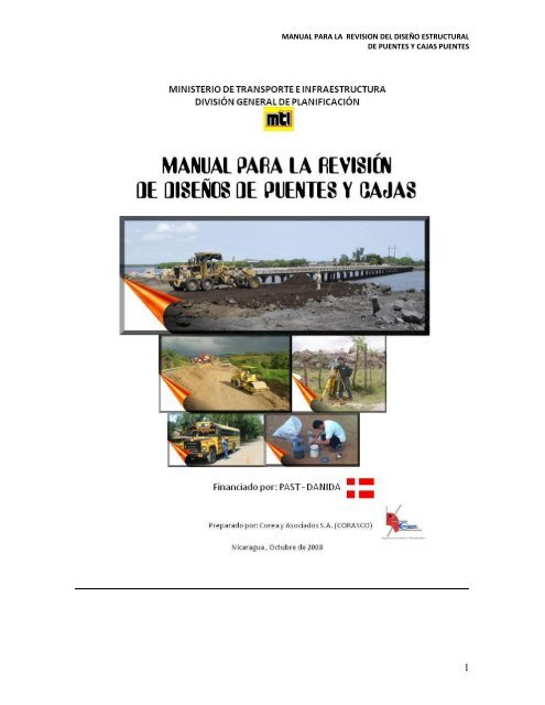
MANUAL PARA LA REVISION DEL DISEÑO ESTRUCTURALDE PUENTES Y CAJAS PUENTES1
MANUAL PARA LA REVISION DEL DISEÑO ESTRUCTURALDE PUENTES Y CAJAS PUENTESEl presente “<strong>Manual</strong> para la Revisión <strong>de</strong> <strong>Diseño</strong>s <strong>Estructural</strong>es <strong>de</strong> <strong>Puentes</strong> y <strong>Cajas</strong>” esuno <strong>de</strong> los resultados <strong>de</strong>l Estudio “Realización <strong>de</strong> <strong>Manual</strong>es Técnicos para la Revisión yAprobación <strong>de</strong> Estudios y <strong>Diseño</strong>s <strong>de</strong> Carreteras” que se llevó a cabo con la colaboración yfinanciamiento <strong>de</strong>l Real Gobierno <strong>de</strong> Dinamarca por medio <strong>de</strong>l Programa <strong>de</strong> Apoyo alSector Transporte – PAST-DANIDA y con el <strong>de</strong>cisivo apoyo y dirección <strong>de</strong>l Ministerio <strong>de</strong>Transporte e Infraestructura por medio <strong>de</strong> la División General <strong>de</strong> Planificación (DGP).Dicha consultoría fue realizada por la firma <strong>de</strong> Ingenieros Consultores y PlanificadoresCorea y Asociados S.A. (CORASCO), con un equipo <strong>de</strong> los mejores especialistasprofesionales nicaragüenses. La dirección, coordinación y control <strong>de</strong> calidad <strong>de</strong>l estudio <strong>de</strong>consultoría fue llevado a cabo por los Ingenieros Leonardo Zacarías Corea, Manuel ZamoraRivera y Álvaro J. Flores M. por Corasco. El presente manual fue elaborado con laparticipación <strong>de</strong>l Ing. Walter Gómez y un equipo <strong>de</strong> ingenieros <strong>de</strong> la DGP. El Ing. Gómezes un reconocido profesional <strong>de</strong> la ingeniería estructural con estudios especiales y con más<strong>de</strong> 25 años <strong>de</strong> experiencia profesional en la ejecución <strong>de</strong> proyectos viales.Este primer esfuerzo para normalizar los procesos <strong>de</strong> revisión <strong>de</strong> estudios y diseños viales,implicará necesariamente el estudio <strong>de</strong> los mismos e iniciar su aplicación pronta enproyectos <strong>de</strong> infraestructura y transporte, esta herramienta será <strong>de</strong> mucha utilidad tanto paralos equipos <strong>de</strong> profesionales <strong>de</strong>l área <strong>de</strong> planificación como para las áreas que administranproyectos <strong>de</strong> construcciones viales puesto que todos están involucrados en diversosmomentos en el proceso <strong>de</strong> elaboración y revisión <strong>de</strong> estudios y diseños. Es necesarioa<strong>de</strong>más, iniciar una etapa <strong>de</strong> monitoreo para llevar registros acerca <strong>de</strong> los resultados en laaplicabilidad <strong>de</strong> estos manuales <strong>de</strong> forma que en el futuro se puedan hacer las a<strong>de</strong>cuacionesy actualizaciones que se consi<strong>de</strong>ren necesarias.Managua, Nicaragua, 3 <strong>de</strong> Octubre <strong>de</strong> 20082
INDICEMANUAL PARA LA REVISION DEL DISEÑO ESTRUCTURALDE PUENTES Y CAJAS PUENTESCAPÍTULO I. INTRODUCCIÓN ......................................................................................... 5CAPÍTULO II.OBJETIVOS DEL MANUAL PARA REVISIÓN DEL DISEÑOESTRUCTURAL DE PUENTES CARRETEROS Y CAJASPUENTES DE CONCRETO ....................................................................... 6OBJETIVO GENERAL .............................................................................................................................. 6OBJETIVOS ESPECIFICOS..................................................................................................................... 6CAPÍTULO III.CAPÍTULO IV.CAPÍTULO V.ESTRUCTURA DEL MANUAL PARA LA REVISIÓN DEL DISEÑOESTRUCTURAL DE PUENTES CARRETEROS Y CAJASPUENTES DE CONCRETO ....................................................................... 7ESTUDIOS NO ESTRUCTURALES REQUERIDOS, QUE SEDEBERAN DE PRESENTAR JUNTO CON EL DISEÑOESTRUCTURAL DE LOS PUENTES CARRETEROS Y CAJASPUENTES DE CONCRETO. ...................................................................... 9ESTRUCTURACION DE LOS TRES TIPOS DE PUENTES MASFRECUENTEMENTE CONSTRUIDOS EN NICARAGUA ................. 12Puente Carretero Tipo I ......................................................................................................................... 12Puente Carretero Tipo II ........................................................................................................................ 14Puente Carretero Tipo III ....................................................................................................................... 16CAPÍTULO VI.CAPÍTULO VII.CAPÍTULO VIII.PROCESO PARA LA APROBACIÓN DEL DISEÑO ESTRUCTURALDE PUENTES CARRETEROS Y CAJAS PUENTES DE CONCRETOREFORZADO ............................................................................................. 19METODOLOGÍA DEL PROCESO PARA LA REVISIÓN DELDISEÑO ESTRUCTURAL DE PUENTES CARRETEROS ................ 21METODOLOGÍA DEL PROCESO PARA LA REVISIÓN DELDISEÑO ESTRUCTURAL DE CAJAS PUENTES DE CONCRETOREFORZADO ............................................................................................. 26CAPÍTULO IX. GLOSARIO Y DEFINICIONES DE TERMINOS ................................... 29ANEXO Nº 1:ANEXO Nº 2:REALIZACIÓN DE ESTUDIO DE FALLAMIENTO GEOLÓGICOLOCAL, REQUERIDO PARA PUENTES CARRETEROS,CONFORME A LA UBICACIÓN Y TIPO DE CARRETERA ............ 38USO DEL CONCRETO REFORZADO O LA MAMPOSTERÍA ENESTRIBOS DE PUENTES CARRETEROS, CONFORME A LAUBICACIÓN Y TIPO DE CARRETERA ................................................ 40ANEXO 3: LISTA DE CHEQUEO DE PRESENTACIÓN DE LOSDOCUMENTOS REQUERIDOS PARA LA REVISIÓNESTRUCTURAL DE PUENTES CARRETEROS Y CAJAS PUENTESDE CONCRETO REFORZADO .............................................................. 42ANEXO 4: PUENTES CARRETEROS TIPO I : LISTA DE CHEQUEO YREVISIÓN DEL CONTENIDO DE LA MEMORIA DE CALCULOSESTRUCTURALES ................................................................................... 443
MANUAL PARA LA REVISION DEL DISEÑO ESTRUCTURALDE PUENTES Y CAJAS PUENTESANEXO 5: PUENTES CARRETEROS TIPO I: LISTA DE CHEQUEO YREVISIÓN DEL CONTENIDO DE LOS PLANOSCONSTRUCTIVOS ESTRUCTURALES ............................................... 49ANEXO 6: PUENTES CARRETEROS TIPO II: LISTA DE CHEQUEO YREVISIÓN DEL CONTENIDO DE LA MEMORIA DE CALCULOSESTRUCTURALES ................................................................................... 55ANEXO Nº 7: PUENTES CARRETEROS TIPO II: LISTA DE CHEQUEO YREVISIÓN DEL CONTENIDO DE LOS PLANOS CONSTRUCTIVOSESTRUCTURALES ................................................................................... 60ANEXO Nº 8: PUENTES CARRETEROS TIPO III: LISTA DE CHEQUEO YREVISIÓN DEL CONTENIDO DE LA MEMORIA DE CALCULOSESTRUCTURALES ................................................................................... 66ANEXO Nº 9: PUENTES CARRETEROS TIPO III: LISTA DE CHEQUEO YREVISIÓN DEL CONTENIDO DE LOS PLANOS CONSTRUCTIVOSESTRUCTURALES ................................................................................... 71ANEXO Nº 10: CAJAS PUENTES DE CONCRETO REFORZADO: LISTA DECHEQUEO Y REVISIÓN DEL CONTENIDO DE LA MEMORIA DECALCULOS ESTRUCTURALES ............................................................ 77ANEXO Nº 11: CAJAS PUENTES DE CONCRETO REFORZADO: LISTA DECHEQUEO Y REVISIÓN DEL CONTENIDO DE LOS PLANOSCONSTRUCTIVOS ESTRUCTURALES ............................................... 814
MANUAL PARA LA REVISION DEL DISEÑO ESTRUCTURALDE PUENTES Y CAJAS PUENTESCAPÍTULO I.INTRODUCCIÓNEl presente <strong>Manual</strong> para la Revisión <strong>de</strong>l <strong>Diseño</strong> <strong>Estructural</strong> <strong>de</strong> un PuenteCarretero, o <strong>de</strong> una Caja Puente, forma parte <strong>de</strong>l Estudio: “Realización <strong>de</strong><strong>Manual</strong>es Técnicos para la Revisión y Aprobación <strong>de</strong> Estudios y <strong>Diseño</strong>s <strong>de</strong>Carreteras, Evaluación <strong>de</strong> los Estudios Económicos y Elaboración <strong>de</strong>Términos <strong>de</strong> Referencias para Proyectos <strong>de</strong> Carreteras”. Dicho Estudiofinanciado con recursos provenientes <strong>de</strong> una donación <strong>de</strong>l Reino <strong>de</strong> Dinamarca através <strong>de</strong>l programa PAST – DANIDA al Gobierno <strong>de</strong> Nicaragua, lo realizó la firmaconsultora COREA Y ASOCIADOS, S.A. –CORASCO-, contratada por elMinisterio <strong>de</strong> Transporte e Infraestructura (MTI),<strong>de</strong>spués <strong>de</strong> ganar la Licitación porRegistro LxR-008-2007.Des<strong>de</strong> mediados <strong>de</strong>l siglo XX a la fecha, se han <strong>de</strong>sarrollado muchos nuevosconocimientos relacionados al <strong>Diseño</strong> <strong>Estructural</strong> <strong>de</strong> un Puente Carretero o <strong>de</strong> unaCaja Puente, tanto en los aspectos teóricos como prácticos, gracias a trabajos <strong>de</strong>Investigación sobre las propieda<strong>de</strong>s <strong>de</strong> los materiales, en el <strong>de</strong>sarrollo <strong>de</strong> nuevosy mejores materiales, en métodos más racionales y precisos sobre elcomportamiento estructural, en el uso <strong>de</strong> técnicas computacionales cada vez másavanzadas, en el estudio <strong>de</strong> eventos externos particularmente peligrosos parapuentes y cajas puente, tales como sismos y socavación.Este <strong>Manual</strong>, aunque no es un <strong>Manual</strong> para <strong>Diseño</strong> <strong>Estructural</strong>, sino para laRevisión <strong>de</strong>l <strong>Diseño</strong> <strong>Estructural</strong>, <strong>de</strong>berá ser revisado y actualizado periódicamente,incorporándole nuevos Tipos <strong>de</strong> <strong>Puentes</strong> Carreteros, <strong>de</strong> acuerdo con el <strong>de</strong>sarrollo<strong>de</strong> la infraestructura vial <strong>de</strong> Nicaragua, y conforme a los avances <strong>de</strong> losconocimientos relacionados al <strong>Diseño</strong> <strong>Estructural</strong>, principalmente para los Listados<strong>de</strong> Chequeo <strong>de</strong>l contenido <strong>de</strong> la Memoria <strong>de</strong> Cálculos <strong>Estructural</strong>es, que sepresentan en el <strong>Manual</strong>.El presente manual, es un primer intento, que podrá ser enriquecido con lascríticas y los aportes, que puedan hacer los usuarios <strong>de</strong>l mismo y los ingenierosestructurales en general, para mejorar las revisiones <strong>de</strong>l <strong>Diseño</strong> <strong>Estructural</strong> <strong>de</strong><strong>Puentes</strong> Carreteros y <strong>Cajas</strong> <strong>Puentes</strong> <strong>de</strong> Concreto Reforzado, por parte <strong>de</strong> laDivisión General <strong>de</strong> Planificación (DGP) <strong>de</strong>l Ministerio <strong>de</strong> Transporte eInfraestructura (MTI).5
MANUAL PARA LA REVISION DEL DISEÑO ESTRUCTURALDE PUENTES Y CAJAS PUENTESCAPÍTULO II. OBJETIVOS DEL MANUAL PARA REVISIÓNDEL DISEÑO ESTRUCTURAL DE PUENTES CARRETEROS YCAJAS PUENTES DE CONCRETOOBJETIVO GENERALEl Objetivo General <strong>de</strong>l “MANUAL PARA REVISIÓN DEL DISEÑOESTRUCTURAL DE PUENTES CARRETEROS Y CAJAS PUENTES DECONCRETO”, es contribuir al Fortalecimiento Institucional <strong>de</strong>l Ministerio <strong>de</strong>Transporte e Infraestructura (MTI), mejorando los procedimientos <strong>de</strong> la Revisión<strong>de</strong> los <strong>Diseño</strong>s <strong>Estructural</strong>es <strong>de</strong> proyectos viales (<strong>Puentes</strong> Carreteros y <strong>Cajas</strong><strong>Puentes</strong> <strong>de</strong> Concreto), para su posterior aprobación.OBJETIVOS ESPECIFICOSLos Objetivos Específicos <strong>de</strong>l “MANUAL PARA REVISIÓN DEL DISEÑOESTRUCTURAL DE PUENTES CARRETEROS Y CAJAS PUENTES DECONCRETO”, son los siguientes:Que el “MANUAL PARA REVISIÓN DEL DISEÑO ESTRUCTURAL DEPUENTES CARRETEROS Y CAJAS PUENTES DE CONCRETO”, seaaplicado, a nivel nacional, por la División General <strong>de</strong> Planificación (DGP)<strong>de</strong>l Ministerio <strong>de</strong> Transporte e Infraestructura (MTI), en cualquier proyectoque involucre la construcción, rehabilitación y/o ampliación <strong>de</strong> un PuenteCarretero, estandarizando, <strong>de</strong> esta manera, los criterios <strong>de</strong> Revisión <strong>de</strong>l<strong>Diseño</strong> <strong>Estructural</strong> y la presentación <strong>de</strong> los Estudios correspondientes,relacionados al mismo.Mejorar las Revisiones <strong>de</strong> los <strong>Diseño</strong>s <strong>Estructural</strong>es (<strong>Puentes</strong> Carreteros y<strong>Cajas</strong> <strong>Puentes</strong> <strong>de</strong> Concreto), mediante la aplicación <strong>de</strong>l “MANUAL PARAREVISIÓN DEL DISEÑO ESTRUCTURAL DE PUENTES CARRETEROS YCAJAS PUENTES DE CONCRETO”, por parte <strong>de</strong> la División General <strong>de</strong>Planificación (DGP) <strong>de</strong>l Ministerio <strong>de</strong> Transporte e Infraestructura (MTI).Que el “MANUAL PARA REVISIÓN DEL DISEÑO ESTRUCTURAL DEPUENTES CARRETEROS Y CAJAS PUENTES DE CONCRETO”, sirva <strong>de</strong>guía a la División General <strong>de</strong> Planificación (DGP) <strong>de</strong>l Ministerio <strong>de</strong>Transporte e Infraestructura (MTI), sobre los criterios y tópicos relevantesque se <strong>de</strong>ben <strong>de</strong> consi<strong>de</strong>rar en un proceso <strong>de</strong> Revisión simple <strong>de</strong>l <strong>Diseño</strong><strong>Estructural</strong> (<strong>Puentes</strong> Carreteros y <strong>Cajas</strong> <strong>Puentes</strong> <strong>de</strong> Concreto).6
MANUAL PARA LA REVISION DEL DISEÑO ESTRUCTURALDE PUENTES Y CAJAS PUENTESCAPÍTULO III. ESTRUCTURA DEL MANUAL PARA LAREVISIÓN DEL DISEÑO ESTRUCTURAL DE PUENTESCARRETEROS Y CAJAS PUENTES DE CONCRETOESTRUCTURA DEL MANUALEl <strong>Manual</strong> para la Revisión <strong>de</strong>l <strong>Diseño</strong> <strong>Estructural</strong> <strong>de</strong> un Puente Carretero, o<strong>de</strong> una Caja Puente, está estructurado conforme el contenido, en ocho capítulosy diez anexos, en a<strong>de</strong>cuación al contenido establecido en los Términos <strong>de</strong>Referencia.El CAPITULO I <strong>de</strong> este <strong>Manual</strong> es una Introducción al mismo, don<strong>de</strong> brevementese manifiestan, tanto los antece<strong>de</strong>ntes como la justificación <strong>de</strong> tener un <strong>Manual</strong>para la Revisión <strong>de</strong>l <strong>Diseño</strong> <strong>Estructural</strong> <strong>de</strong> un Puente Carretero, o <strong>de</strong> unaCaja Puente, que sea revisado y actualizado periódicamente.En el CAPITULO II, se encuentran tanto el Objetivo General como los ObjetivosEspecíficos <strong>de</strong>l presente <strong>Manual</strong> para la Revisión <strong>de</strong>l <strong>Diseño</strong> <strong>Estructural</strong> <strong>de</strong> unPuente Carretero, o <strong>de</strong> una Caja Puente.En el CAPITULO III, se presenta la Estructura <strong>de</strong>l <strong>Manual</strong>, con una breve<strong>de</strong>scripción <strong>de</strong>l contenido <strong>de</strong> todos y cada uno <strong>de</strong> los Capítulos que lo forman.El CAPITULO IV, se refiere a todos los estudios no estructurales requeridos, parala Revisión <strong>de</strong>l <strong>Diseño</strong> <strong>Estructural</strong> <strong>de</strong> un Puente Carretero, o <strong>de</strong> una CajaPuente, que se <strong>de</strong>berán <strong>de</strong> presentar junto con el <strong>Diseño</strong> <strong>Estructural</strong>.En el CAPITULO V, se presentan los diferentes componentes <strong>de</strong> la estructuración<strong>de</strong> los tres tipos <strong>de</strong> puentes <strong>carreteros</strong>, más frecuentemente construidos enNicaragua. Estos tres tipos <strong>de</strong> puentes <strong>carreteros</strong> son los que se encuentranincluidos en el presente <strong>Manual</strong> para la Revisión <strong>de</strong>l <strong>Diseño</strong> <strong>Estructural</strong> <strong>de</strong> unPuente Carretero.En el CAPITULO VI, se refiere al Proceso para la Aprobación <strong>de</strong>l <strong>Diseño</strong><strong>Estructural</strong> <strong>de</strong> <strong>Puentes</strong> Carreteros y <strong>Cajas</strong> <strong>Puentes</strong> <strong>de</strong> Concreto Reforzado.En el CAPITULO VII, se refiere a la Metodología <strong>de</strong>l Proceso para la Revisión<strong>de</strong>l <strong>Diseño</strong> <strong>Estructural</strong> <strong>de</strong> <strong>Puentes</strong> Carreteros..El CAPITULO VIII, se refiere a la Metodología <strong>de</strong>l Proceso para la Revisión <strong>de</strong>l<strong>Diseño</strong> <strong>Estructural</strong> <strong>de</strong> <strong>Cajas</strong> <strong>Puentes</strong> <strong>de</strong> Concreto Reforzado..7
MANUAL PARA LA REVISION DEL DISEÑO ESTRUCTURALDE PUENTES Y CAJAS PUENTESEn el CAPITULO IX, se presenta un Glosario <strong>de</strong> Términos con sus respectivas<strong>de</strong>finiciones.El ANEXO 1, presenta una tabla para el Estudio <strong>de</strong> Fallamiento Geológicolocal, requerido para <strong>Puentes</strong> Carreteros, conforme a la ubicación y tipo <strong>de</strong>carreteraEl ANEXO 2, presenta una tabla indicando el uso <strong>de</strong>l concreto reforzado o lamampostería en estribos <strong>de</strong> puentes <strong>carreteros</strong>, conforme a la ubicación y tipo <strong>de</strong>carretera.En el ANEXO 3, se presenta una Lista <strong>de</strong> Chequeo <strong>de</strong> Presentación <strong>de</strong> losDocumentos Requeridos para la Revisión <strong>Estructural</strong> <strong>de</strong> <strong>Puentes</strong> Carreterosy <strong>Cajas</strong> <strong>Puentes</strong> <strong>de</strong> Concreto Reforzado.En el ANEXO 4, se presenta una Lista <strong>de</strong> Chequeo y Revisión <strong>de</strong>l contenido <strong>de</strong>la Memoria <strong>de</strong> Cálculos <strong>Estructural</strong>es, para <strong>Puentes</strong> Carreteros Tipo I.En el ANEXO 5, se presenta una Lista <strong>de</strong> Chequeo y Revisión <strong>de</strong>l contenido<strong>de</strong> los Planos Constructivos <strong>Estructural</strong>es, para <strong>Puentes</strong> Carreteros Tipo I.En el ANEXO 6, se presenta una Lista <strong>de</strong> Chequeo y Revisión <strong>de</strong>l contenido <strong>de</strong>la Memoria <strong>de</strong> Cálculos <strong>Estructural</strong>es, para <strong>Puentes</strong> Carreteros Tipo II.En el ANEXO 7, se presenta una Lista <strong>de</strong> Chequeo y Revisión <strong>de</strong>l contenido<strong>de</strong> los Planos Constructivos <strong>Estructural</strong>es, para <strong>Puentes</strong> Carreteros Tipo II.En el ANEXO 8, se presenta una Lista <strong>de</strong> Chequeo y Revisión <strong>de</strong>l contenido <strong>de</strong>la Memoria <strong>de</strong> Cálculos <strong>Estructural</strong>es, para <strong>Puentes</strong> Carreteros Tipo III.El ANEXO 9, presenta una Lista <strong>de</strong> Chequeo y Revisión <strong>de</strong>l contenido <strong>de</strong> losPlanos Constructivos <strong>Estructural</strong>es, para <strong>Puentes</strong> Carreteros Tipo III.En el ANEXO 10, se presenta una Lista <strong>de</strong> Chequeo y Revisión <strong>de</strong>l contenido<strong>de</strong> la Memoria <strong>de</strong> Cálculos <strong>Estructural</strong>es, para <strong>Cajas</strong> <strong>Puentes</strong> <strong>de</strong> ConcretoReforzado.El ANEXO 11, presenta una Lista <strong>de</strong> Chequeo y Revisión <strong>de</strong>l contenido <strong>de</strong> losPlanos Constructivos <strong>Estructural</strong>es, para <strong>Cajas</strong> <strong>Puentes</strong> <strong>de</strong> ConcretoReforzado.8
MANUAL PARA LA REVISION DEL DISEÑO ESTRUCTURALDE PUENTES Y CAJAS PUENTESCAPÍTULO IV. ESTUDIOS NO ESTRUCTURALESREQUERIDOS, QUE SE DEBERAN DE PRESENTAR JUNTOCON EL DISEÑO ESTRUCTURAL DE LOS PUENTESCARRETEROS Y CAJAS PUENTES DE CONCRETO.Para la Revisión <strong>de</strong>l <strong>Diseño</strong> <strong>Estructural</strong> <strong>de</strong> un Puente Carretero, o <strong>de</strong> una CajaPuente <strong>de</strong> Concreto Reforzado, se requiere la presentación al Ministerio <strong>de</strong>Transporte e Infraestructura (MTI), <strong>de</strong> diferentes estudios no estructurales, juntocon la Memoria <strong>de</strong> Cálculos <strong>Estructural</strong>es y los Planos Constructivos<strong>Estructural</strong>es. Los diferentes estudios no estructurales, requeridos a presentar,son los siguientes:ESTUDIO TOPOGRAFICOLos Estudios Topográficos <strong>de</strong>berán mostrar la topografía actual <strong>de</strong>l sitio <strong>de</strong>construcción <strong>de</strong>l puente mediante planos <strong>de</strong> curvas <strong>de</strong> nivel, junto consecciones transversales a cada 20 metros en un tramo no menor <strong>de</strong> 200metros, 100 metros aguas arriba y 100 metros aguas abajo <strong>de</strong>l puente, parael caso <strong>de</strong> que el obstáculo que salva el puente es un cauce pluvial o elcauce <strong>de</strong> un río. Estos estudios <strong>de</strong>ben incluir, <strong>de</strong> ser posible, losantece<strong>de</strong>ntes <strong>de</strong>l terreno en términos <strong>de</strong> los movimientos <strong>de</strong> masas <strong>de</strong>suelo, erosión <strong>de</strong> suelos y rocas y serpenteo <strong>de</strong> los cursos <strong>de</strong> agua.ESTUDIO DE MECANICA DE SUELOSSe <strong>de</strong>be llevar a cabo un Estudio <strong>de</strong> Mecánica <strong>de</strong> Suelos que incluyason<strong>de</strong>os o perforaciones y ensayos <strong>de</strong>l suelo, a fin <strong>de</strong> obtener informaciónpertinente y suficiente para el diseño <strong>de</strong> las fundaciones <strong>de</strong> lasubestructura.ESTUDIO DE FALLAMIENTO GEOLÓGICO LOCALPara los <strong>Puentes</strong> Carreteros ubicados en la Región <strong>de</strong>l Pacífico y en laRegión Central <strong>de</strong> Nicaragua, y que correspondan a los Tipos <strong>de</strong>Carretera: Troncal Principal y Trocal Secundario, y para los <strong>Puentes</strong>Carreteros ubicados en la Región <strong>de</strong>l Caribe <strong>de</strong> Nicaragua, y quecorrespondan al Tipo <strong>de</strong> Carretera: Troncal Principal, se requerirá larealización <strong>de</strong> un Estudio <strong>de</strong> Fallamiento Geológico Local (Ver9
MANUAL PARA LA REVISION DEL DISEÑO ESTRUCTURALDE PUENTES Y CAJAS PUENTESFlujograma 1, y Anexo 1), que incluirá una microzonificación sísmica porFallamiento Geológico. Si el Estudio confirma la existencia <strong>de</strong> una FallaGeológica Activa,.en la zona <strong>de</strong> cruce propuesta para el Puente Carretero,se <strong>de</strong>berán <strong>de</strong> estudiar otras alternativas <strong>de</strong> ubicación <strong>de</strong> dicho puente,incluyendo la posibilidad <strong>de</strong> <strong>de</strong>splazar el cauce, a fin <strong>de</strong> que el cruce que<strong>de</strong>ubicado en Zona Buena, libre <strong>de</strong> Fallas Geológicas.ESTUDIO HIDROLOGICOPor medio <strong>de</strong> la Hidrología se analiza la cuenca vertiente y se cuantificanlos regímenes <strong>de</strong> Caudales, Niveles y Sedimentos <strong>de</strong>l río o <strong>de</strong>l caucepluvial, en el tramo <strong>de</strong> influencia <strong>de</strong>l Puente Carretero.ESTUDIO HIDRAULICOLos objetivos <strong>de</strong> los estudios hidráulicos son el dimensionamiento <strong>de</strong>lpuente en lo referente a altura y luces, el encauzamiento <strong>de</strong> la corriente y laprotección <strong>de</strong> estribos y pilas contra socavación y ataques <strong>de</strong> la corriente.La <strong>de</strong>terminación <strong>de</strong> las variables Hidráulicas se basa en el análisis <strong>de</strong> lainformación Hidrológica, en los registros <strong>de</strong> los levantamientostopográficos, en los análisis granulométricos y <strong>de</strong> clasificación <strong>de</strong> muestras<strong>de</strong>l material que conforma el lecho y las orillas <strong>de</strong>l cauce, y en los estudios<strong>de</strong> Geotecnia y <strong>de</strong> Geomorfología. Se requiere como informaciónindispensable para la realización <strong>de</strong>l cálculo hidráulico, levantamientostopográficos <strong>de</strong> las secciones transversales <strong>de</strong>l cauce a cada 20 metros enun tramo no menor <strong>de</strong> 200 metros, 100 metros aguas arriba y 100 metrosaguas abajo <strong>de</strong>l puente, para el caso <strong>de</strong> que el obstáculo que salva elPuente Carretero es un cauce pluvial o el cauce <strong>de</strong> un río.ESTUDIO DE SOCAVACIONSe <strong>de</strong>be <strong>de</strong> realizar un Estudio <strong>de</strong> Socavación, que incluya tanto lasocavación localizada en los estribos, pilas o en cualquier otra obstrucción<strong>de</strong>l flujo en el cruce <strong>de</strong> un Puente Carretero; como la socavaciónGeneralizada o <strong>de</strong> Contracción en el cauce. Es muy importante conocer laprofundidad <strong>de</strong> socavación en los estribos y pilas <strong>de</strong> un Puente Carretero,a<strong>de</strong>más <strong>de</strong> los datos proporcionados por el Estudio <strong>de</strong> Mecánica <strong>de</strong> Suelos,para <strong>de</strong> manera integral realizar el diseño estructural <strong>de</strong> las fundaciones <strong>de</strong>los estribos y pilas <strong>de</strong> dicho puente Carretero.10
MANUAL PARA LA REVISION DEL DISEÑO ESTRUCTURALDE PUENTES Y CAJAS PUENTESintermedio <strong>de</strong> la superestructura. Estas pilas serán <strong>de</strong> concretoreforzado, para <strong>Puentes</strong> Carreteros ubicados en cualquier sitio <strong>de</strong>Nicaragua. La fundación <strong>de</strong> estas Pilas, será una zapata <strong>de</strong> concretoreforzado, que se podrá apoyar sobre pilotes en caso <strong>de</strong> que el Estudio<strong>de</strong> Mecánica <strong>de</strong> Suelos lo requiera.Puente Carretero Tipo IILa construcción <strong>de</strong> la superestructura <strong>de</strong>l Puente Carretero Tipo II, se encuentraformada <strong>de</strong> la manera siguiente:Losa <strong>de</strong> concreto reforzado. La superficie <strong>de</strong> esta losa servirá comosuperficie <strong>de</strong> rodamiento y su sección transversal <strong>de</strong>berá <strong>de</strong> tener unperalte variable, formando una curva en la superficie <strong>de</strong> rodamiento,<strong>de</strong>s<strong>de</strong> un mínimo en sus extremos hasta un máximo en el centro; paradrenar el agua pluvial o cualquier otro líquido que acci<strong>de</strong>ntalmente se<strong>de</strong>rrame sobre la superficie, hacia orificios <strong>de</strong> drenaje colocados en losextremos <strong>de</strong> la losa, don<strong>de</strong> se inicia la construcción <strong>de</strong>l An<strong>de</strong>n Peatonal.Esta losa <strong>de</strong> concreto reforzado se encuentra soportada por largueros(vigas) <strong>de</strong> concreto pretensado.Largueros (vigas) <strong>de</strong> concreto pretensado. Los largueros <strong>de</strong>concreto pretensado son vigas longitudinales que son soportadas ensus extremos en la viga <strong>de</strong> asiento <strong>de</strong> concreto reforzado <strong>de</strong> losEstribos, para el caso <strong>de</strong> que se trate <strong>de</strong> un Puente Carretero <strong>de</strong> un soloclaro. En el caso <strong>de</strong> <strong>Puentes</strong> Carreteros <strong>de</strong> dos o más claros, loslargueros también serán soportados en uno o en ambos extremos, en laviga <strong>de</strong> asiento <strong>de</strong> la Pila o las Pilas, según el caso. Los largueros <strong>de</strong>concreto pretensado pue<strong>de</strong>n estar integrados a la losa <strong>de</strong> concretoreforzado que soportan, por medio <strong>de</strong> conectores <strong>de</strong> acero, que se<strong>de</strong>jan empotrados en las vigas <strong>de</strong> concreto pretensado, durante sufabricación.An<strong>de</strong>n peatonal con sus barandales. En Nicaragua, generalmentelos puentes <strong>carreteros</strong> tienen en ambos extremos <strong>de</strong> su seccióntransversal un andén peatonal con su respectivo barandal. El an<strong>de</strong>npeatonal podrá ser <strong>de</strong> concreto reforzado. Los barandales podrán estarformados por columnas y vigas <strong>de</strong> acero, o por columnas y vigas <strong>de</strong>concreto reforzado, o por una combinación <strong>de</strong> columnas <strong>de</strong> concretoreforzado y vigas <strong>de</strong> acero.La construcción <strong>de</strong> la subestructura <strong>de</strong>l Puente Carretero Tipo II, se encuentraformada <strong>de</strong> la manera siguiente:14
MANUAL PARA LA REVISION DEL DISEÑO ESTRUCTURALDE PUENTES Y CAJAS PUENTESVigas <strong>de</strong> asiento <strong>de</strong> concreto reforzado. Estas vigas <strong>de</strong> asiento <strong>de</strong>concreto reforzado, se encuentran ubicadas en el extremo superior <strong>de</strong>los Estribos, y <strong>de</strong> la Pila o las Pilas, en caso <strong>de</strong> <strong>Puentes</strong> Carreteros <strong>de</strong>dos o más claros; que soportan los extremos <strong>de</strong> los largueros (vigas) <strong>de</strong>concreto pretensado. Las vigas <strong>de</strong> asiento <strong>de</strong> concreto reforzado,forman parte <strong>de</strong> las Pilas y <strong>de</strong> los Estribos <strong>de</strong> concreto reforzado o <strong>de</strong>los Estribos <strong>de</strong> Mampostería.Estribos <strong>de</strong> concreto reforzado. Los Estribos <strong>de</strong> concreto reforzado,se pue<strong>de</strong>n usar para <strong>Puentes</strong> Carreteros ubicados en cualquier sitio <strong>de</strong>Nicaragua, Ver Flujograma 2 y Anexo 2, que se refieren al Uso <strong>de</strong>lConcreto Reforzado o la Mampostería en Estribos <strong>de</strong> <strong>Puentes</strong>Carreteros, conforme a la Ubicación y Tipo <strong>de</strong> Carretera. Estánformados por una zona central, que termina en su nivel superior en unaviga <strong>de</strong> asiento <strong>de</strong> concreto reforzado, que soportará a los largueros(vigas) <strong>de</strong> concreto pretensado; y por los aletones <strong>de</strong> concretoreforzado, ubicados a ambos lados <strong>de</strong> la zona central. La fundación <strong>de</strong>estos Estribos, es una zapata <strong>de</strong> concreto reforzado, que se podráapoyar sobre pilotes en caso <strong>de</strong> que el Estudio <strong>de</strong> Mecánica <strong>de</strong> Sueloslo requiera.Estribos <strong>de</strong> mampostería. Los Estribos <strong>de</strong> mampostería (concretociclópeo <strong>de</strong> piedra bolón), se pue<strong>de</strong>n usar, únicamente, para <strong>Puentes</strong>Carreteros <strong>de</strong> Caminos Vecinales, ubicados en la Región Central, ypara los <strong>Puentes</strong> Carreteros <strong>de</strong>: Troncal Secundario, ColectoraPrincipal, Colectora Secundaria y Caminos Vecinales, ubicados en laRegión <strong>de</strong>l Caribe. Ver Flujograma 2 y Anexo 2, que se refieren al Uso<strong>de</strong>l Concreto Reforzado o la Mampostería en Estribos <strong>de</strong> <strong>Puentes</strong>Carreteros, conforme a la Ubicación y Tipo <strong>de</strong> Carretera. En la partesuperior estos Estribos <strong>de</strong> mampostería terminan en una viga <strong>de</strong>asiento <strong>de</strong> concreto reforzado, quesoportará a los largueros (vigas) <strong>de</strong> concreto pretensado. La fundación<strong>de</strong> estos Estribos, será <strong>de</strong>l mismo material usado en los Estribos. No sepodrán usar Estribos <strong>de</strong> mampostería, si el Estudio <strong>de</strong> Mecánica <strong>de</strong>Suelos requiere el uso <strong>de</strong> Pilotes. Si el Estudio <strong>de</strong> Mecánica <strong>de</strong> Suelosrequiere el uso <strong>de</strong> Pilotes para las fundaciones, únicamente se podránusar Estribos <strong>de</strong> Concreto Reforzado.Pilas <strong>de</strong> concreto reforzado. Para el caso <strong>de</strong> <strong>Puentes</strong> Carreteros, condos o más claros, don<strong>de</strong> son necesarias las pilas como apoyo intermedio <strong>de</strong>la superestructura. Estas pilas serán <strong>de</strong> concreto reforzado, para <strong>Puentes</strong>Carreteros ubicados en cualquier sitio <strong>de</strong> Nicaragua. La fundación <strong>de</strong>estas Pilas, será una zapata <strong>de</strong> concreto reforzado, que se podrá apoyarsobre pilotes en caso <strong>de</strong> que el Estudio <strong>de</strong> Mecánica <strong>de</strong> Suelos lo requiera.15
MANUAL PARA LA REVISION DEL DISEÑO ESTRUCTURALDE PUENTES Y CAJAS PUENTESPuente Carretero Tipo IIILa construcción <strong>de</strong> la superestructura <strong>de</strong>l Puente Carretero Tipo III, se encuentraformada <strong>de</strong> la manera siguiente:Losa <strong>de</strong> concreto reforzado. La superficie <strong>de</strong> esta losa servirá comosuperficie <strong>de</strong> rodamiento y su sección transversal <strong>de</strong>berá <strong>de</strong> tener unperalte variable, formando una curva en la superficie <strong>de</strong> rodamiento,<strong>de</strong>s<strong>de</strong> un mínimo en sus extremos hasta un máximo en el centro; paradrenar el agua pluvial o cualquier otro líquido que acci<strong>de</strong>ntalmente se<strong>de</strong>rrame sobre la superficie, hacia orificios <strong>de</strong> drenaje colocados en losextremos <strong>de</strong> la losa, don<strong>de</strong> se inicia la construcción <strong>de</strong>l An<strong>de</strong>n Peatonal.Esta losa <strong>de</strong> concreto reforzado se encuentra soportada por largueros(vigas) <strong>de</strong> concreto pretensado.Largueros (vigas) <strong>de</strong> concreto reforzado prefabricado. Loslargueros <strong>de</strong> concreto reforzado prefabricado son vigas longitudinalesque son soportadas en sus extremos en la viga <strong>de</strong> asiento <strong>de</strong> concretoreforzado <strong>de</strong> los Estribos, para el caso <strong>de</strong> que se trate <strong>de</strong> un PuenteCarretero <strong>de</strong> un solo claro. En el caso <strong>de</strong> <strong>Puentes</strong> Carreteros <strong>de</strong> dos omás claros, los largueros también serán soportados en uno o en ambosextremos, en la viga <strong>de</strong> asiento <strong>de</strong> la Pila o las Pilas, según el caso. Loslargueros <strong>de</strong> concreto reforzado prefabricado pue<strong>de</strong>n estar integrados ala losa <strong>de</strong> concreto reforzado que soportan, por medio <strong>de</strong> conectores <strong>de</strong>acero, que se <strong>de</strong>jan empotrados en las vigas <strong>de</strong> concreto reforzadoprefabricado, durante su fabricación.An<strong>de</strong>n peatonal con sus barandales. En Nicaragua, generalmentelos puentes <strong>carreteros</strong> tienen en ambos extremos <strong>de</strong> su seccióntransversal un an<strong>de</strong>n peatonal con su respectivo barandal. El andénpeatonal podrá ser <strong>de</strong> concreto reforzado. Los barandales podrán estarformados por columnas y vigas <strong>de</strong> acero, o por columnas y vigas <strong>de</strong>concreto reforzado, o por una combinación <strong>de</strong> columnas <strong>de</strong> concretoreforzado y vigas <strong>de</strong> acero.La construcción <strong>de</strong> la subestructura <strong>de</strong>l Puente Carretero Tipo III, se encuentraformada <strong>de</strong> la manera siguiente:Vigas <strong>de</strong> asiento <strong>de</strong> concreto reforzado. Estas vigas <strong>de</strong> asiento <strong>de</strong>concreto reforzado, se encuentran ubicadas en el extremo superior <strong>de</strong>los Estribos, y <strong>de</strong> la Pila o las Pilas, en caso <strong>de</strong> <strong>Puentes</strong> Carreteros <strong>de</strong>dos o más claros; que soportan los extremos <strong>de</strong> los largueros (vigas) <strong>de</strong>concreto reforzado prefabricado. Las vigas <strong>de</strong> asiento <strong>de</strong> concreto16
MANUAL PARA LA REVISION DEL DISEÑO ESTRUCTURALDE PUENTES Y CAJAS PUENTESreforzado, forman parte <strong>de</strong> las Pilas y <strong>de</strong> los Estribos <strong>de</strong> concretoreforzado o <strong>de</strong> los Estribos <strong>de</strong> Mampostería.Estribos <strong>de</strong> concreto reforzado. Los Estribos <strong>de</strong> concreto reforzado,se pue<strong>de</strong>n usar para <strong>Puentes</strong> Carreteros ubicados en cualquier sitio <strong>de</strong>Nicaragua, Ver Flujograma 2 y Anexo 2, que se refieren al Uso <strong>de</strong>lConcreto Reforzado o la Mampostería en Estribos <strong>de</strong> <strong>Puentes</strong>Carreteros, conforme a la Ubicación y Tipo <strong>de</strong> Carretera. Estánformados por una zona central, que termina en su nivel superior en unaviga <strong>de</strong> asiento <strong>de</strong> concreto reforzado, que soportará a los largueros(vigas) <strong>de</strong> concreto reforzado prefabricado; y por los aletones <strong>de</strong>concreto reforzado, ubicados a ambos lados <strong>de</strong> la zona central. Lafundación <strong>de</strong> estos Estribos, es una zapata <strong>de</strong> concreto reforzado, quese podrá apoyar sobre pilotes en caso <strong>de</strong> que el Estudio <strong>de</strong> Mecánica<strong>de</strong> Suelos lo requiera.Estribos <strong>de</strong> mampostería. Los Estribos <strong>de</strong> mampostería (concretociclópeo <strong>de</strong> piedra bolón), se pue<strong>de</strong>n usar, únicamente, para <strong>Puentes</strong>Carreteros <strong>de</strong> Caminos Vecinales, ubicados en la Región Central, ypara los <strong>Puentes</strong> Carreteros <strong>de</strong>: Troncal Secundario, ColectoraPrincipal, Colectora Secundaria y Caminos Vecinales, ubicados en laRegión <strong>de</strong>l Caribe. Ver Flujograma 2 y Anexo 2, que se refieren al Uso<strong>de</strong>l Concreto Reforzado o la Mampostería en Estribos <strong>de</strong> <strong>Puentes</strong>Carreteros, conforme a la Ubicación y Tipo <strong>de</strong> Carretera. En la partesuperior estos Estribos <strong>de</strong> mampostería terminan en una viga <strong>de</strong> asiento<strong>de</strong> concreto reforzado, que soportará a los largueros (vigas) <strong>de</strong>concreto reforzado prefabricado.La fundación <strong>de</strong> estos Estribos, será <strong>de</strong>l mismo material usado en losEstribos. No se podrán usar Estribos <strong>de</strong> mampostería, si el Estudio <strong>de</strong>Mecánica <strong>de</strong> Suelos requiere el uso <strong>de</strong> Pilotes. Si el Estudio <strong>de</strong>Mecánica <strong>de</strong> Suelos requiere el uso <strong>de</strong> Pilotes para las fundaciones,unicamente se podrán usar Estribos <strong>de</strong> Concreto Reforzado.Pilas <strong>de</strong> concreto reforzado. Para el caso <strong>de</strong> <strong>Puentes</strong> Carreteros, condos o más claros, don<strong>de</strong> son necesarias las pilas como apoyointermedio <strong>de</strong> la superestructura. Estas pilas serán <strong>de</strong> concretoreforzado, para <strong>Puentes</strong> Carreteros ubicados en cualquier sitio <strong>de</strong>Nicaragua. La fundación <strong>de</strong> estas Pilas, será una zapata <strong>de</strong> concretoreforzado, que se podrá apoyar sobre pilotes en caso <strong>de</strong> que el Estudio<strong>de</strong> Mecánica <strong>de</strong> Suelos lo requiera.17
MANUAL PARA LA REVISION DEL DISEÑO ESTRUCTURALDE PUENTES Y CAJAS PUENTESFLUJOGRAMA 2USO DEL CONCRETO REFORZADO O LA MAMPOSTERÍA EN ESTRIBOS DEPUENTES CARRETEROS, CONFORME A LA UBICACIÓN Y TIPO DE CARRETERA.DELPACIFICOCHINANDEGALEONMANAGUACARAZOMASAYAGRANADARIVASTRONCALPRINCIPALTRONCALSECUNDARIOCOLECTORAPRINCIPALCOLECTORASECUNDARIACAMINOSVECINALESNUEVASEGOVIA TRONCALMADRIZTRONCALPRINCIPALTRONCALSECUNDARIOCONCRETOREFORZADOREGIÓNCENTRALESTELIJINOTEGAMATAGALPADEGABOACOCOLECTORAPRINCIPALCOLECTORASECUNDARIACHONTALESCAMINOSVECINALESRIO SAN JUANREGIONAUTONOMADEL ATLÁNTICONORTE (RAAN)TRONCALPRINCIPALCONCRETOREFORZADOOMAMPOSTERIADELCARIBEREGIONAUTONOMADEL ATLÁNTICOSUR (RAAS)TRONCALSECUNDARIOCOLECTORAPRINCIPALCOLECTORASECUNDARIACAMINOSVECINALES18
MANUAL PARA LA REVISION DEL DISEÑO ESTRUCTURALDE PUENTES Y CAJAS PUENTESCAPÍTULO VI. PROCESO PARA LA APROBACIÓN DELDISEÑO ESTRUCTURAL DE PUENTES CARRETEROS YCAJAS PUENTES DE CONCRETO REFORZADOEl proceso para la aprobación <strong>de</strong>l <strong>Diseño</strong> <strong>Estructural</strong> <strong>de</strong> <strong>Puentes</strong> Carreteros y<strong>Cajas</strong> <strong>Puentes</strong> <strong>de</strong> Concreto reforzado se inicia con la recepción <strong>de</strong> todos losdocumentos requeridos para el <strong>Diseño</strong> <strong>Estructural</strong> <strong>de</strong>l Puente Carretero o <strong>de</strong> laCaja Puente, en la División General <strong>de</strong> Planificación (DGP) <strong>de</strong>l Ministerio <strong>de</strong>Transporte e Infraestructura (MTI). Luego todos estos documentos se envían a laDivisión <strong>de</strong> Preinversión, don<strong>de</strong> se asignan al Ingeniero Revisor <strong>Estructural</strong>, paraque proceda a la Revisión <strong>de</strong> todos los documentos <strong>de</strong>l <strong>Diseño</strong> <strong>Estructural</strong>,conforme a lo indicado en el presente <strong>Manual</strong>.Cuando el Ingeniero Revisor <strong>Estructural</strong> finaliza con la Revisión <strong>de</strong> todos losdocumentos <strong>de</strong>l <strong>Diseño</strong> <strong>Estructural</strong> <strong>de</strong>l Puente Carretero o <strong>de</strong> la Caja Puente,elabora un Informe <strong>de</strong> Revisión <strong>Estructural</strong> y lo envía, junto con todos losdocumentos antes mencionados, al Director <strong>de</strong> la División <strong>de</strong> Preinversión.Dependiendo <strong>de</strong> los resultados indicados en el Informe <strong>de</strong> Revisión <strong>Estructural</strong> y<strong>de</strong> la evaluación <strong>de</strong> los mismos por parte <strong>de</strong>l Director <strong>de</strong> la División <strong>de</strong>Preinversión, el proyecto <strong>de</strong>l <strong>Diseño</strong> <strong>Estructural</strong> <strong>de</strong>l Puente Carretero o <strong>de</strong> la CajaPuente, se aprueba o no se aprueba. Si se aprueba, el Director <strong>de</strong> la División <strong>de</strong>Preinversión envía toda la documentación al expediente <strong>de</strong>l proyecto, ysimultáneamente envía un Memorandum Interno <strong>de</strong> aprobación <strong>de</strong>l proyecto alDirector <strong>de</strong> la División General <strong>de</strong> Planificación. Luego el Director <strong>de</strong> la DivisiónGeneral <strong>de</strong> Planificación, envía una carta <strong>de</strong> aprobación <strong>de</strong>l Proyecto al Consultor.Si no se aprueba, pue<strong>de</strong> ser por las dos situaciones siguientes: 1) el Director <strong>de</strong> laDivisión <strong>de</strong> Preinversión, encuentra que el Informe <strong>de</strong> Revisión <strong>Estructural</strong> no lesatisface por estar incompleto y/o por falta <strong>de</strong> claridad, en tal caso lo <strong>de</strong>vuelve alIngeniero Revisor <strong>Estructural</strong>, solicitándole correcciones y aclaraciones a dichoInforme <strong>de</strong> Revisión <strong>Estructural</strong>, luego el Ingeniero Revisor <strong>Estructural</strong>, atien<strong>de</strong>todos los comentarios, y elabora un nuevo Informe <strong>de</strong> Revisión <strong>Estructural</strong> y loenvía al Director <strong>de</strong> la División <strong>de</strong> Preinversión; 2) el Director <strong>de</strong> la División <strong>de</strong>Preinversión, encuentra que el Informe <strong>de</strong> Revisión <strong>Estructural</strong> le satisface y envíaun Memorandum Interno <strong>de</strong> no aprobación <strong>de</strong>l proyecto al Director <strong>de</strong> la DivisiónGeneral <strong>de</strong> Planificación. Luego el Director <strong>de</strong> la División General <strong>de</strong> Planificación,envía una carta <strong>de</strong> no aprobación <strong>de</strong>l Proyecto al Consultor, solicitándole hacer lascorrecciones y aclaraciones <strong>de</strong>l caso. Posteriormente el Consultor atien<strong>de</strong> todaslas correcciones y aclaraciones solicitadas por el Director <strong>de</strong> la División General<strong>de</strong> Planificación, y envía <strong>de</strong> nuevo el proyecto a la División General <strong>de</strong>Planificación (Ver Flujograma 3)19
MANUAL PARA LA REVISION DEL DISEÑO ESTRUCTURALDE PUENTES Y CAJAS PUENTESFLUJOGRAMA 3PROCESO PARA LA APROBACIÓN DEL DISEÑO ESTRUCTURAL DE PUENTESCARRETEROS Y CAJAS PUENTES DE CONCRETO REFORZADORECEPCIÓN DE TODOSLOS DOCUMENTOS DELDISEÑO ESTRUCTURALDEL PUENTE CARRETEROO DE LA CAJA PUENTE, ENLA DIVISIÓN GENERAL DEPLANIFICACIÓN (dgp)EL CONSULTORATIENDDE LASCORRECCIONES YACLARACIONESSOLICITADAS POR ELDIRECTOR DE LADGP.EL DIRECTOS DE LADIVISIÓN DEPREINVERSIÓN ENVÍAMEMORANDUMINTERNO DE “NOAPROBACIÓN” DELPROYECTO ALDIRECTOR GENERAL DELA DGPEL DIRECTOR DE LADIVISIÓN GENERAL DEPLANIFICACIÓN ENVIACARTA DE APROBACIÓNDEL PROYECTO ALCONSULTOREL DIRECTOR DE LADIVISIÓN DEPREINVERSIÓN ENVIAMEMORANDUMINTERNO DEAPROBACIÓN DELPROYECTO ALDIRECTOR DE LADIVISIÓN GENERAL DEPLANIFICACIÓNDIVISIÓN DEPREINVERSIÓNEL DIRECTOR DE LA DPGENVIA CARTA ELCONSULTOR SOLICITANDOHACER LASCORRECCIONES YACLARACIONES DEL CASOSE ATIENDEN LOSCOMENTARIOS DELDIRECTOR DE LA DIVISIÓNDE PREINVERSIÓN Y SEELABORA INFORME DEREVISIÓN ESTRUCTURALCORREGIDOSE DEVIELVE ALINGENIERO REVISORESTRUCTURALSOLICITÁNDOLECORRECCIONES YACLARACIONES ALINFORME ESTRUCTURALNO SE APRUEBASE ENVÍA EXPEDIENTEAL EXPEDIENTE DELPROYECTOINGENIEROSUPERVISORESTRUCTURALREVISIÓN DE TODOS LOSDOCUMENTOS DEL DISEÑOESTRUCTURAL CONFORMEAL MANUALELABORACIÓN DE INFORMEDE REVISIÓN ESTRUCTURAL,INCLUYENDO LOSCOMENTARIOS CONFORME ALA LISTA DE CHEQUEOCORRESPONDIENTERECIBE EL INFORME DEREVISIÓN ESTRUCTURAL,INCLUYENDO LOSCOMENTARIOS CONFORME ALA LISTA DE CHEQUEOCORRESPONDIENTEDEPENDIENDO DE LOSRESULTADOS INDICADOS ENEL INFORME Y DE LAEVALUACIÓN DE LOSMISMOS POR PARTE DELDIRECTOR DE LA DIVISIÒNDE PREINVERSIÓNSE APRUEBA20
MANUAL PARA LA REVISION DEL DISEÑO ESTRUCTURALDE PUENTES Y CAJAS PUENTESCAPÍTULO VII. METODOLOGÍA DEL PROCESO PARA LAREVISIÓN DEL DISEÑO ESTRUCTURAL DE PUENTESCARRETEROSLa Revisión <strong>de</strong>l <strong>Diseño</strong> <strong>Estructural</strong> <strong>de</strong> <strong>Puentes</strong> Carreteros, es una parte que seencuentra <strong>de</strong>ntro <strong>de</strong>l Proceso para la aprobación <strong>de</strong>l <strong>Diseño</strong> <strong>Estructural</strong> <strong>de</strong><strong>Puentes</strong> Carreteros y <strong>Cajas</strong> <strong>Puentes</strong> <strong>de</strong> Concreto reforzado (Ver Capítulo VI). Eneste Capítulo se tratará <strong>de</strong> la Metodología <strong>de</strong>l Proceso para la Revisión <strong>de</strong>l <strong>Diseño</strong><strong>Estructural</strong> <strong>de</strong> <strong>Puentes</strong> Carreteros.El proceso para la Revisión <strong>de</strong>l <strong>Diseño</strong> <strong>Estructural</strong> <strong>de</strong> <strong>Puentes</strong> Carreteros, se iniciacuando la División <strong>de</strong> Preinversión le entrega al Ingeniero Revisor <strong>Estructural</strong>,previamente asignado, para que proceda a la Revisión <strong>de</strong> todos los documentos<strong>de</strong>l <strong>Diseño</strong> <strong>Estructural</strong>, conforme a lo indicado en el presente <strong>Manual</strong>.Como primer paso el Ingeniero Revisor <strong>Estructural</strong>, constata que recibe todos losdocumentos requeridos para la Revisión <strong>de</strong>l <strong>Diseño</strong> <strong>Estructural</strong> <strong>de</strong>l PuenteCarretero. Los documentos requeridos son <strong>de</strong> dos tipos: 1) documentosestructurales y 2) documentos no estructurales, que están en íntima relación conel <strong>Diseño</strong> <strong>Estructural</strong> <strong>de</strong>l Puente Carretero. Los documentos estructurales son laMemoria <strong>de</strong> Cálculos <strong>Estructural</strong>es y los Planos Constructivos <strong>Estructural</strong>es. Losdocumentos no estructurales son el Estudio Topográfico, el Estudio <strong>de</strong> Mecánica<strong>de</strong> Suelos, el Estudio <strong>de</strong> Fallamiento Geológico Local, el Estudio Hidrológico, elEstudio Hidráulico, el Estudio <strong>de</strong> Socavación Generalizada, y el Estudio <strong>de</strong>Socavación Localizada. El Anexo 3, consiste en una Lista <strong>de</strong> Chequeo <strong>de</strong>Presentación <strong>de</strong> los Documentos Requeridos para la Revisión <strong>Estructural</strong> <strong>de</strong><strong>Puentes</strong> Carreteros y <strong>Cajas</strong> <strong>Puentes</strong> <strong>de</strong> Concreto Reforzado. En la primeracolumna <strong>de</strong> esta Lista <strong>de</strong> Chequeo, se indica el nombre <strong>de</strong> cada uno <strong>de</strong> losdocumentos, luego en las siguientes tres columnas se <strong>de</strong>berá <strong>de</strong> indicar si sepresentó el documento (SI), si no se presentó (NO), o si no aplica (N/A). La últimacolumna <strong>de</strong> la Lista <strong>de</strong> Chequeo, es para hacer los comentarios <strong>de</strong>l caso, que elIngeniero Revisor <strong>Estructural</strong> crea conveniente. Por ejemplo: No se presentóEstudio <strong>de</strong> Fallamiento Geológico Local, para un Puente ubicado en una carretera“Colectora Principal” <strong>de</strong>l Departamento <strong>de</strong> Madriz. En este caso, revisamos en elAnexo 1 o en el Flujograma 1, si es requisito o no es requisito, la realización <strong>de</strong> unEstudio <strong>de</strong> Fallamiento Geológico Local para un Puente Carretero en unaColectora Principal <strong>de</strong>l Departamento <strong>de</strong> Madriz. Como resultado encontramosque no es requisito, por lo tanto, en la Lista <strong>de</strong> Chequeo <strong>de</strong>l Anexo 3, señalamos omarcamos que no aplica (N/A), la presentación <strong>de</strong>l documento “Estudio <strong>de</strong>Fallamiento Geológico Local”, para ese Puente Carreto, haciendo los comentarios<strong>de</strong>l caso en la última columna.21
MANUAL PARA LA REVISION DEL DISEÑO ESTRUCTURALDE PUENTES Y CAJAS PUENTESDespués <strong>de</strong> que el Ingeniero Revisor <strong>Estructural</strong>, ha constatado si ha recibido o noha recibido todos los documentos requeridos para la Revisión <strong>de</strong>l <strong>Diseño</strong><strong>Estructural</strong> <strong>de</strong>l Puente Carretero, proce<strong>de</strong>rá a verificar si tanto la Memoria <strong>de</strong>Cálculos <strong>Estructural</strong>es, como los Planos Constructivos <strong>Estructural</strong>es, contienen losdiferentes puntos señalados en la Lista <strong>de</strong> Chequeo <strong>de</strong>l contenido <strong>de</strong> la Memoria<strong>de</strong> Cálculos <strong>Estructural</strong>es, para <strong>Puentes</strong> Carreteros; y en la Lista <strong>de</strong> Chequeo <strong>de</strong>lcontenido <strong>de</strong> los Planos Constructivos <strong>Estructural</strong>es.Es importante hacer énfasis <strong>de</strong> que al inicio <strong>de</strong> la Memoria <strong>de</strong> Cálculos<strong>Estructural</strong>es, el Diseñador <strong>Estructural</strong>, <strong>de</strong>berá <strong>de</strong> hacer un resumen explicativo<strong>de</strong>l contenido <strong>de</strong> dicha Memoria. En este resumen se <strong>de</strong>berá <strong>de</strong> incluir, entreotros, la filosofía estructural empleada, la metodología, la relación <strong>de</strong> los cálculosestructurales con los datos proporcionados en los Estudios no <strong>Estructural</strong>es, y lossupuestos estructurales, si existen. A<strong>de</strong>más cada punto indicado en la Lista <strong>de</strong>Chequeo <strong>de</strong> la Memoria <strong>de</strong> Cálculos <strong>Estructural</strong>es, <strong>de</strong>berá <strong>de</strong> ir acompañado <strong>de</strong>notas explicativas y aclaratorias, a fin <strong>de</strong> facilitar la revisión. También el Diseñador<strong>Estructural</strong> <strong>de</strong>l Puente Carretero <strong>de</strong>berá <strong>de</strong> incluir, entre otros, el Método <strong>de</strong><strong>Diseño</strong> <strong>Estructural</strong> empleado, los Códigos y/o Reglamentos y <strong>Manual</strong>es que seusarán para el <strong>Diseño</strong> <strong>Estructural</strong>, y las fatigas <strong>de</strong> los diferentes materiales que seusarán el la construcción <strong>de</strong>l Puente Carretero. Después <strong>de</strong> familiarizado con losdatos básicos <strong>de</strong>l proyecto y <strong>de</strong>pendiendo <strong>de</strong> los resultados <strong>de</strong>l chequeo <strong>de</strong> todoslos puntos anteriormente mencionados, el Ingeniero Revisor <strong>Estructural</strong>, realizaráuna evaluación <strong>de</strong> los mismos y proce<strong>de</strong>rá a hacer los comentarios que estimeconvenientes al respecto, colocándolos en la columna correspondiente <strong>de</strong> la Lista<strong>de</strong> Chequeo.Posteriormente, el Ingeniero Revisor <strong>Estructural</strong> proce<strong>de</strong>rá a constatar si laMemoria <strong>de</strong> Cálculos <strong>Estructural</strong>es presentada, contiene todos los puntosrelevantes que aplican al Puente Carretero, objeto <strong>de</strong> revisión, conforme a la Lista<strong>de</strong> Chequeo y Revisión <strong>de</strong>l Contenido <strong>de</strong> la Memoria <strong>de</strong> Cálculos <strong>Estructural</strong>escorrespondiente (Ver Anexo 4, Anexo 6 y Anexo 8). La existencia en la Memoria<strong>de</strong> Cálculos <strong>Estructural</strong>es <strong>de</strong> los puntos que aplican, serán señalados con una X,en la columna correspondiente a “SI” <strong>de</strong> la Presentación <strong>de</strong> cada contenido <strong>de</strong> laLista <strong>de</strong> Chequeo. Si algún punto relevante que aplica al Puente Carretero objeto<strong>de</strong> revisión, no aparece tratado en la Memoria <strong>de</strong> Cálculos <strong>Estructural</strong>es, elIngeniero Revisor <strong>Estructural</strong>, <strong>de</strong>berá <strong>de</strong> señalar con una X, en la columnacorrespondiente a “NO” <strong>de</strong> la Presentación <strong>de</strong> cada contenido <strong>de</strong> la Lista <strong>de</strong>Chequeo y realizar los comentarios correspondientes, colocándolos en la columnaque correspon<strong>de</strong> <strong>de</strong> dicha Lista <strong>de</strong> Chequeo.Es importante mencionar que para cada uno <strong>de</strong> los tres tipos <strong>de</strong> <strong>Puentes</strong>Carreteros más frecuentemente construidos en Nicaragua (Ver Capítulo V), en laLista <strong>de</strong> Chequeo y Revisión <strong>de</strong>l Contenido <strong>de</strong> la Memoria <strong>de</strong> Cálculos<strong>Estructural</strong>es se han contemplado puntos que correspon<strong>de</strong>n al caso <strong>de</strong> ampliación<strong>de</strong> un Puente Carretero.22
MANUAL PARA LA REVISION DEL DISEÑO ESTRUCTURALDE PUENTES Y CAJAS PUENTESun Informe <strong>de</strong> Revisión <strong>Estructural</strong>, y lo envía al Director <strong>de</strong> la División <strong>de</strong>Preinversión.Dependiendo <strong>de</strong> los resultados indicados en el Informe <strong>de</strong> Revisión <strong>Estructural</strong> y<strong>de</strong> la evaluación <strong>de</strong> los mismos por parte <strong>de</strong>l Director <strong>de</strong> la División <strong>de</strong>Preinversión, el Proyecto se aprueba, no se aprueba o se <strong>de</strong>vuelve al IngenieroRevisor <strong>Estructural</strong>, solicitándole correcciones y aclaraciones al Informe <strong>de</strong>Revisión <strong>Estructural</strong> (Ver Flujograma 4).24
MANUAL PARA LA REVISION DEL DISEÑO ESTRUCTURALDE PUENTES Y CAJAS PUENTESFLUJOGRAMA 4PROCESO PARA LA REVISIÓN DEL DISEÑO ESTRUCTURAL DE PUENTESCARRETEROS Y CAJAS PUENTES DE CONCRETO REFORZADOEL DIRECTOR DE LA DIVISIÓNDE PREINVERSION ENVIA ALINGENIERO REVISORASIGNADO TODOS LOSDOCUMENTOS DEL DISEÑOESTRUCTURAL DEL PUENTECARRETERO O DE LA CAJAPUENTE PARA SU REVISIÓNESTRUCTURALEL INGENIEROREVISOR ASIGNADOINICIA LA REVISIÓNESTRUCTURALCONSTATANDO QUERECIBE TODOS LOSDOCUMENTOSREQUERIDOSSE FAMILIARIZA CONLOS DATOS BÁSICOSDEL PROYECTO, TALESCOMO UBICACIÓN,FILOSOFIAESTRUCTURAL,.MATERIALES A USAR, YDIMENSIONES, ENTREOTROS.SE APRUEBADEPENDIENDO DE LOSRESULTADOS INDICADOS ENEL INFORME DE REVISIÓNESTRUCTURAL Y DE LAEVALUACIÓN DE LOS MISMOSPOR PARTE DEL DIRECTORDE LA DIVISIÓN DEPREINVERSIONEL INGENIERO REVISORASIGNADO ELABORAINFORME DE REVISIÓNESTRUCTURAL Y LO ENVIAAL DIRECTOR DE LADIVISIÓN DE PREINVERSIÓNREVISA LOS CALCULOS DECADA UNO DE LOSCONTENIDOS DE LAMEMORIA DE CALCULOSESTRUCTURALESPRESENTADA, VERIFICANDOADEMÁS, SI ESTANCOMPLETOS, SI ESTAN DEACUERDO CON LOS ESTUDIOSNO ESTRUCTURALESREQUERIDOS, SI ESTAN DEACUERDO CON LA FILOSOFIAESTRUCTURAL, Y SI LOSSUPUESTOS ESTRUCTURALESSON RAZONABLEMENTEVALIDOS.NO SE APRUEBASE DEVUELVE ALINGENIERO REVISORESTRUCTURALSOLICITÁNDOLECORRECCIONES YACLARACIONES ALINFORMEESTRUCTURALEL INGENIEROREVISOR ASIGNADOATIENDE LOSCOMENTARIOS DELDIRECTOR DE LADIVISIÓN DEPREINVERSIÓNENCUENTRA QUE LASCARGAS VIVAS DEDISEÑO NO SON LASCORRECTASENCUENTRA QUE LASCARGAS VIVAS DEDISEÑO SON LASCORRECTASCHEQUEA CONFORMEA LA LISTA DECHEQUEO Y REVISIÓNDEL CONTENIDO DE LAMEMORIA DECALCULOSESTRUCTURALES,CONSTATANDO SI SEENCUENTRAN EN LAMEMORIA DECALCULOSPRESENTADA, CADAUNO DE LOSCONTENIDOS.ANOTA EL RESULTADODEL CHEQUEOANTERIOR, EN LASCOLUMNASCORRESPONDIENTESDE LA HOJA DE LALISTA DE CHEQUEO YREVISIÓN DELCONTENIDO DE LAMEMORIA DECALCULOSESTRUCTURALES,COLOCANDO UNA “X”.REVISA SI LAS CARGASVIVAS DE DISEÑO SONLAS CORRECTAS DEACUERDO CON EL TIPODE CARRETERA25
MANUAL PARA LA REVISION DEL DISEÑO ESTRUCTURALDE PUENTES Y CAJAS PUENTESCAPÍTULO VIII. METODOLOGÍA DEL PROCESO PARA LAREVISIÓN DEL DISEÑO ESTRUCTURAL DE CAJASPUENTES DE CONCRETO REFORZADOLa Revisión <strong>de</strong>l <strong>Diseño</strong> <strong>Estructural</strong> <strong>de</strong> <strong>Cajas</strong> <strong>Puentes</strong> <strong>de</strong> Concreto Reforzado, esuna parte que se encuentra <strong>de</strong>ntro <strong>de</strong>l Proceso para la aprobación <strong>de</strong>l <strong>Diseño</strong><strong>Estructural</strong> <strong>de</strong> <strong>Puentes</strong> Carreteros y <strong>Cajas</strong> <strong>Puentes</strong> <strong>de</strong> Concreto reforzado (VerCapítulo VI). En este Capítulo se tratará <strong>de</strong> la Metodología <strong>de</strong>l Proceso para laRevisión <strong>de</strong>l <strong>Diseño</strong> <strong>Estructural</strong> <strong>de</strong> <strong>Cajas</strong> <strong>Puentes</strong> <strong>de</strong> Concreto Reforzado.El proceso para la Revisión <strong>de</strong>l <strong>Diseño</strong> <strong>Estructural</strong> <strong>de</strong> <strong>Cajas</strong> <strong>Puentes</strong> <strong>de</strong> ConcretoReforzado, se inicia cuando la División <strong>de</strong> Preinversión le entrega al IngenieroRevisor <strong>Estructural</strong>, previamente asignado, para que proceda a la Revisión <strong>de</strong>todos los documentos <strong>de</strong>l <strong>Diseño</strong> <strong>Estructural</strong>, conforme a lo indicado en elpresente <strong>Manual</strong>.Como primer paso el Ingeniero Revisor <strong>Estructural</strong>, constata que recibe todos losdocumentos requeridos para la Revisión <strong>de</strong>l <strong>Diseño</strong> <strong>Estructural</strong> <strong>de</strong> la Caja Puente<strong>de</strong> Concreto Reforzado. Los documentos requeridos son <strong>de</strong> dos tipos: 1)documentos estructurales y 2) documentos no estructurales, que están en íntimarelación con el <strong>Diseño</strong> <strong>Estructural</strong> <strong>de</strong> la Caja Puente <strong>de</strong> Concreto Reforzado. Losdocumentos estructurales son la Memoria <strong>de</strong> Cálculos <strong>Estructural</strong>es y los PlanosConstructivos <strong>Estructural</strong>es. Los documentos no estructurales son el EstudioTopográfico, el Estudio <strong>de</strong> Mecánica <strong>de</strong> Suelos, el Estudio <strong>de</strong> FallamientoGeológico Local, el Estudio Hidrológico, el Estudio Hidráulico, el Estudio <strong>de</strong>Socavación Generalizada, y el Estudio <strong>de</strong> Socavación Localizada. El Anexo 3,consiste en una Lista <strong>de</strong> Chequeo <strong>de</strong> Presentación <strong>de</strong> los DocumentosRequeridos para la Revisión <strong>Estructural</strong> <strong>de</strong> <strong>Puentes</strong> Carreteros y <strong>Cajas</strong> <strong>Puentes</strong><strong>de</strong> Concreto Reforzado. Para el caso <strong>de</strong> <strong>Cajas</strong> <strong>Puentes</strong> <strong>de</strong> Concreto Reforzado,no será requerida la presentación <strong>de</strong>l Estudio <strong>de</strong> Fallamiento Geológico Local. Enla primera columna <strong>de</strong> esta Lista <strong>de</strong> Chequeo, se indica el nombre <strong>de</strong> cada uno <strong>de</strong>los documentos, luego en las siguientes tres columnas se <strong>de</strong>berá <strong>de</strong> indicar si sepresentó el documento (SI), si no se presentó (NO), o si no aplica (N/A). La últimacolumna <strong>de</strong> la Lista <strong>de</strong> Chequeo, es para hacer los comentarios <strong>de</strong>l caso, que elIngeniero Revisor <strong>Estructural</strong> crea conveniente. Por ejemplo: No se presentóEstudio <strong>de</strong> Fallamiento Geológico Local, para una Caja Puente <strong>de</strong> ConcretoReforzado ubicada en una carretera “Colectora Principal” <strong>de</strong>l Departamento <strong>de</strong>León. En este caso, y en cualquier otro caso, si se trata <strong>de</strong> una Caja Puente, noserá requisito la realización <strong>de</strong> un Estudio <strong>de</strong> Fallamiento Geológico Local. Portanto, como no26
MANUAL PARA LA REVISION DEL DISEÑO ESTRUCTURALDE PUENTES Y CAJAS PUENTESes requisito, en la Lista <strong>de</strong> Chequeo <strong>de</strong>l Anexo 3, señalamos o marcamos que noaplica (N/A), la presentación <strong>de</strong>l documento “Estudio <strong>de</strong> Fallamiento GeológicoLocal”, haciendo los comentarios <strong>de</strong>l caso en la última columna.Después <strong>de</strong> que el Ingeniero Revisor <strong>Estructural</strong>, ha constatado si ha recibido o noha recibido todos los documentos requeridos para la Revisión <strong>de</strong>l <strong>Diseño</strong><strong>Estructural</strong> <strong>de</strong> la Caja Puente <strong>de</strong> Concreto Reforzado, proce<strong>de</strong>rá a verificar si tantola Memoria <strong>de</strong> Cálculos <strong>Estructural</strong>es, como los Planos Constructivos<strong>Estructural</strong>es, contienen los diferentes puntos señalados en la Lista <strong>de</strong> Chequeo<strong>de</strong>l contenido <strong>de</strong> la Memoria <strong>de</strong> Cálculos <strong>Estructural</strong>es, para <strong>Cajas</strong> <strong>Puentes</strong> <strong>de</strong>Concreto Reforzado; y en la Lista <strong>de</strong> Chequeo <strong>de</strong>l contenido <strong>de</strong> los PlanosConstructivos <strong>Estructural</strong>es.Es importante hacer énfasis <strong>de</strong> que al inicio <strong>de</strong> la Memoria <strong>de</strong> Cálculos<strong>Estructural</strong>es, el Diseñador <strong>Estructural</strong>, <strong>de</strong>berá <strong>de</strong> hacer un resumen explicativo<strong>de</strong>l contenido <strong>de</strong> dicha Memoria. En este resumen se <strong>de</strong>berá <strong>de</strong> incluir, entreotros, la filosofía estructural empleada, la metodología, la relación <strong>de</strong> los cálculosestructurales con los datos proporcionados en los Estudios no <strong>Estructural</strong>es, y lossupuestos estructurales, si existen. A<strong>de</strong>más cada punto indicado en la Lista <strong>de</strong>Chequeo <strong>de</strong> la Memoria <strong>de</strong> Cálculos <strong>Estructural</strong>es, <strong>de</strong>berá <strong>de</strong> ir acompañado <strong>de</strong>notas explicativas y aclaratorias, a fin <strong>de</strong> facilitar la revisión. También el Diseñador<strong>Estructural</strong> <strong>de</strong> la Caja Puente <strong>de</strong> Concreto Reforzado <strong>de</strong>berá <strong>de</strong> incluir, entreotros, el Método <strong>de</strong> <strong>Diseño</strong> <strong>Estructural</strong> empleado, los Códigos y/o Reglamentos y<strong>Manual</strong>es que se usarán para el <strong>Diseño</strong> <strong>Estructural</strong>, y las fatigas <strong>de</strong> los diferentesmateriales que se usarán el la construcción <strong>de</strong> la Caja Puente. Después <strong>de</strong>familiarizado con los datos básicos <strong>de</strong>l proyecto y <strong>de</strong>pendiendo <strong>de</strong> los resultados<strong>de</strong>l chequeo <strong>de</strong> todos los puntos anteriormente mencionados, el Ingeniero Revisor<strong>Estructural</strong>, realizará una evaluación <strong>de</strong> los mismos y proce<strong>de</strong>rá a hacer loscomentarios que estime convenientes al respecto, colocándolos en la columnacorrespondiente <strong>de</strong> la Lista <strong>de</strong> Chequeo.Posteriormente, el Ingeniero Revisor <strong>Estructural</strong> proce<strong>de</strong>rá a constatar si laMemoria <strong>de</strong> Cálculos <strong>Estructural</strong>es presentada, contiene todos los puntosrelevantes que aplican a la Caja Puente, objeto <strong>de</strong> revisión, conforme a la Lista <strong>de</strong>Chequeo y Revisión <strong>de</strong>l Contenido <strong>de</strong> la Memoria <strong>de</strong> Cálculos <strong>Estructural</strong>escorrespondiente (Ver Anexo 10, y Anexo 11). La existencia en la Memoria <strong>de</strong>Cálculos <strong>Estructural</strong>es <strong>de</strong> los puntos que aplican, serán señalados con una X, enla columna correspondiente a “SI” <strong>de</strong> la Presentación <strong>de</strong> cada contenido <strong>de</strong> laLista <strong>de</strong> Chequeo. Si algún punto relevante que aplica a la Caja Puente objeto <strong>de</strong>revisión, no aparece tratado en la Memoria <strong>de</strong> Cálculos <strong>Estructural</strong>es, el IngenieroRevisor <strong>Estructural</strong>, <strong>de</strong>berá <strong>de</strong> señalar con una X, en la columna correspondientea “NO” <strong>de</strong> la Presentación <strong>de</strong> cada contenido <strong>de</strong> la Lista <strong>de</strong> Chequeo y realizar loscomentarios correspondientes, colocándolos en la columna que correspon<strong>de</strong> <strong>de</strong>dicha Lista <strong>de</strong> Chequeo.Es importante mencionar que únicamente para cada uno <strong>de</strong> los tres tipos <strong>de</strong><strong>Puentes</strong> Carreteros más frecuentemente construidos en Nicaragua (Ver Capítulo27
MANUAL PARA LA REVISION DEL DISEÑO ESTRUCTURALDE PUENTES Y CAJAS PUENTESV), en la Lista <strong>de</strong> Chequeo y Revisión <strong>de</strong>l Contenido <strong>de</strong> la Memoria <strong>de</strong> Cálculos<strong>Estructural</strong>es se han contemplado puntos que correspon<strong>de</strong>n al caso <strong>de</strong> ampliación<strong>de</strong> un Puente Carretero. Para las <strong>Cajas</strong> <strong>Puentes</strong> <strong>de</strong> Concreto Reforzado, no se hacontemplado la ampliación en el presente <strong>Manual</strong>.Continuando con la Revisión <strong>Estructural</strong> <strong>de</strong> una Caja Puente <strong>de</strong> ConcretoReforzado, el Ingeniero Revisor <strong>Estructural</strong>, proce<strong>de</strong>rá a chequear si las cargasvivas <strong>de</strong> diseño, presentadas en la Memoria <strong>de</strong> Cálculos <strong>Estructural</strong>es, son lascorrectas <strong>de</strong> acuerdo con el tipo <strong>de</strong> carretera don<strong>de</strong> se encuentra ubicada dichoCaja Puente. Si el Ingeniero Revisor <strong>Estructural</strong>, encuentra que las Cargas Vivas<strong>de</strong> <strong>Diseño</strong> no son las correctas, elabora un Informe <strong>de</strong> Revisión <strong>Estructural</strong>,realizando los comentarios <strong>de</strong>l caso y rechazando el Proyecto, y lo envía alDirector <strong>de</strong> la División <strong>de</strong> Preinversión, quién evaluará dicho Informe y<strong>de</strong>pendiendo <strong>de</strong>l resultado podrá rechazar el proyecto no aprobándolo, o podráenviarlo <strong>de</strong> nuevo al Ingeniero Revisor solicitándole correcciones y aclaraciones alInforme <strong>Estructural</strong>.Si el Ingeniero Revisor <strong>Estructural</strong>, encuentra que las Cargas Vivas <strong>de</strong> <strong>Diseño</strong> sonlas correctas, proce<strong>de</strong> a revisar los cálculos <strong>de</strong> cada uno <strong>de</strong> los contenidos <strong>de</strong> laMemoria <strong>de</strong> Cálculos <strong>Estructural</strong>es presentada, verificando a<strong>de</strong>más, si estáncompletos, si están <strong>de</strong> acuerdo con los estudios no estructurales requeridos, siestán <strong>de</strong> acuerdo con la filosofía estructural, y si los supuestos estructurales sonrazonablemente válidos. Simultáneamente revisa el contenido <strong>de</strong> los PlanosConstructivos <strong>Estructural</strong>es, y chequea cada uno <strong>de</strong> los <strong>de</strong>talles estructurales quese presentan en dichos Planos, conforme a los resultados revisados y que seencuentran correctos <strong>de</strong> la Memoria <strong>de</strong> Cálculos <strong>Estructural</strong>es.Luego realiza todas las anotaciones correspondientes, tanto el la Lista <strong>de</strong>Chequeo y Revisión <strong>de</strong>l Contenido <strong>de</strong> la Memoria <strong>de</strong> Cálculos <strong>Estructural</strong>es para<strong>Cajas</strong> <strong>Puentes</strong>, como en la Lista <strong>de</strong> Chequeo y Revisión <strong>de</strong>l contenido <strong>de</strong> losPlanos Constructivos <strong>Estructural</strong>es. Posteriormente, el Ingeniero Revisor elaboraun Informe <strong>de</strong> Revisión <strong>Estructural</strong>, y lo envía al Director <strong>de</strong> la División <strong>de</strong>Preinversión.Dependiendo <strong>de</strong> los resultados indicados en el Informe <strong>de</strong> Revisión <strong>Estructural</strong> y<strong>de</strong> la evaluación <strong>de</strong> los mismos por parte <strong>de</strong>l Director <strong>de</strong> la División <strong>de</strong>Preinversión, el Proyecto se aprueba, no se aprueba o se <strong>de</strong>vuelve al IngenieroRevisor <strong>Estructural</strong>, solicitándole correcciones y aclaraciones al Informe <strong>de</strong>Revisión <strong>Estructural</strong> (Ver Flujograma 4).28
MANUAL PARA LA REVISION DEL DISEÑO ESTRUCTURALDE PUENTES Y CAJAS PUENTESCAPÍTULO IX.GLOSARIO Y DEFINICIONES DE TERMINOSAASHTO (AMERICAN ASSOCIATION OF STATE HIGHWAY ANDTRANSPORTATION OFFICIALS): El Comité <strong>de</strong> <strong>Puentes</strong> y Estructuras(Committee on Bridges and Structures) <strong>de</strong> la AASHTO está conformadopor los Ingenieros Jefes <strong>de</strong> <strong>Puentes</strong> <strong>de</strong> cada Departamento <strong>de</strong> Caminos<strong>de</strong> los Estados Unidos <strong>de</strong> América, entida<strong>de</strong>s que a<strong>de</strong>más <strong>de</strong> tener a sucargo la responsabilidad <strong>de</strong>l diseño, construcción y mantenimiento <strong>de</strong> lamayoría <strong>de</strong> los puentes en ese país, tienen la responsabilidad, comoComité <strong>de</strong> <strong>Puentes</strong> y Estructuras <strong>de</strong> la AASHTO, <strong>de</strong> publicar yactualizar periódicamente las Especificaciones Estándares para<strong>Puentes</strong> (STANDARD SPECIFICATIONS FOR HIGHWAY BRIDGES).ACERO: Aleación compuesta por hierro, carbono, silicio, azufre,manganeso, fósforo y otros elementos. El principal componente es elhierro, con aproximadamente el 98%.ACERO PARA CONCRETO PREESFORZADO: Elemento <strong>de</strong> acero <strong>de</strong>alta resistencia como alambre, barra, torón, o un paquete (tendón) <strong>de</strong>estos elementos, usado para aplicar fuerzas <strong>de</strong> preesforzado alconcreto.ACI (AMERICAN CONCRETE INSTITUTE): Instituto Americano <strong>de</strong>lConcreto.AISC (AMERICAN INSTITUTE OF STEEL CONSTRUCTION): InstitutoAmericano <strong>de</strong>l Acero.ASCE (AMERICAN SOCIETY OF CIVIL ENGINEERS):Americana <strong>de</strong> Ingenieros Civiles.SociedadASTM (AMERICAN SOCIETY FOR TESTING AND MATERIALS):Sociedad Americana para Ensayos y Materiales.AWS (AMERICAN WELDING SOCIETY):Soldadura.Sociedad Americana <strong>de</strong>ADITIVO: Material que se agrega a una mezcla <strong>de</strong> concreto, antes odurante su mezclado, para modificar sus propieda<strong>de</strong>s.29
MANUAL PARA LA REVISION DEL DISEÑO ESTRUCTURALDE PUENTES Y CAJAS PUENTESAGREGADO: Material granular, tal como arena, piedra triturada ygrava, usado junto con una pasta cementante formada con cemento yagua, para obtener concreto.ANÁLISIS ESTRUCTURAL: Cálculo <strong>de</strong> las fuerzas y las <strong>de</strong>formaciones<strong>de</strong> las estructuras ante solicitaciones <strong>de</strong> cargas.ANÁLISIS ESTRUCTURAL APROXIMADO: Análisis <strong>de</strong> estructuras,que hace uso <strong>de</strong> ciertas hipótesis simplificadoras o aproximacionesrazonables.ANÁLISIS ESTRUCTURAL EXACTO: Análisis teórico <strong>de</strong> lasestructuras.CARGA FACTORIZADA: Es el producto <strong>de</strong> una carga multiplicada porun factor <strong>de</strong> carga.CARGAS MUERTAS: Cargas <strong>de</strong> magnitud constante, que siemprepermanecerán en una sola posición y actuarán sobre la estructura a lolargo <strong>de</strong> su vida, tales como: peso <strong>de</strong> vigas, peso <strong>de</strong> losa <strong>de</strong> concreto,pesos <strong>de</strong> an<strong>de</strong>nes peatonales y barandales, entre otros.CARGAS VIVAS: Cargas que cambian <strong>de</strong> magnitud y posición, comolas cargas <strong>de</strong> camiones cruzando un puente. Las cargas vivas <strong>de</strong> lasEspecificaciones Estándares para <strong>Puentes</strong> Carreteros <strong>de</strong> la AmericanAssociation of State Highway and Transportation Officials(AASHTO), constan <strong>de</strong> camiones estándares i<strong>de</strong>alizados o <strong>de</strong> cargasvivas que son equivalentes a una serie <strong>de</strong> camiones.CARRETERA O CAMINO: Vía <strong>de</strong> comunicación terrestre, don<strong>de</strong>circulan vehículos <strong>de</strong> transporte, con un ancho total comprendido <strong>de</strong>ntro<strong>de</strong>l Derecho <strong>de</strong> Vía.CARRIL: Cualquier subdivisión <strong>de</strong> la superficie <strong>de</strong> rodamiento ocalzada, <strong>de</strong> una carretera, un camino o un puente, que tenga el anchosuficiente para permitir la circulación <strong>de</strong> una fila <strong>de</strong> vehículos.CAUCE ESTABLE: Condición que existe cuando una corriente <strong>de</strong> aguatiene una pendiente y una sección y transversal que permiten que sucauce transporte el agua y los sedimentos entregados <strong>de</strong>s<strong>de</strong> la cuencacolectora sin <strong>de</strong>gradación, agradación, ni erosión significativa <strong>de</strong> lasmárgenes.30
MANUAL PARA LA REVISION DEL DISEÑO ESTRUCTURALDE PUENTES Y CAJAS PUENTESCONCRETO: Mezcla, con o sin aditivos, <strong>de</strong> piedra triturada, grava,arena y una pasta formada por cemento Portland o cualquier otrocemento hidráulico, y agua potable, que al endurecer o fraguar alcanzaelevada resistencia a la compresión.CONCRETO PRESFORZADO: Concreto en el que se han introducidoesfuerzos internos <strong>de</strong> tal magnitud y distribución que los esfuerzosresultantes <strong>de</strong> las cargas externas dadas se equilibran hasta un grado<strong>de</strong>seado. Existen dos tipos <strong>de</strong> concreto presforzado: concretopretensado y concreto postensado.CONCRETO REFORZADO: Combinación <strong>de</strong> concreto y refuerzo <strong>de</strong>acero, don<strong>de</strong> el concreto proporciona la resistencia a la compresión y elacero proporciona la resistencia a la tensión. También se pue<strong>de</strong>consi<strong>de</strong>rar el refuerzo <strong>de</strong> acero, para ayudar al concreto en laresistencia a la compresión.CURSO DE AGUA: Cualquier arroyo, río, laguna, lago u océano.DEGRADACION: Descenso general y progresivo <strong>de</strong>l perfil longitudinal<strong>de</strong>l lecho <strong>de</strong> un cauce como resultado <strong>de</strong> la erosión a largo plazo.DIAFRAGMA: Sistema horizontal o casi horizontal, que actúa paratransmitir las fuerzas laterales a los elementos <strong>de</strong> resistencia verticales.DISEÑO DE ESFUERZO ADMISIBLE: Conocido en idioma ingléscomo ALLOWABLE STRESS DESING, es un método para <strong>de</strong>terminarlas dimensiones <strong>de</strong> los elementos estructurales <strong>de</strong> forma tal que losesfuerzos calculados producidos en los elementos por lascombinaciones <strong>de</strong> esfuerzo admisible no excedan el esfuerzo admisibleespecificado. También se le conoce como DISEÑO DE ESFUERZOSDE TRABAJO.DISEÑO POR FACTOR DE CARGA Y DE RESISTENCIA: Conocidoen idioma inglés como LOAD AND RESÍSTANCE FACTOR DESING(LRFD), es un método para <strong>de</strong>terminar las dimensiones <strong>de</strong> loselementos estructurales utilizando factores <strong>de</strong> carga y <strong>de</strong> resistencia <strong>de</strong>modo que la estructura no alcance el estado límite correspondiente,cuando la estructura está sometida a todas las combinacionesapropiadas <strong>de</strong> carga.31
MANUAL PARA LA REVISION DEL DISEÑO ESTRUCTURALDE PUENTES Y CAJAS PUENTESDISEÑO POR RESISTENCIA: Conocido en idioma inglés comoSTRENGTH DESING, es un método para <strong>de</strong>terminar las dimensiones<strong>de</strong> los elementos estructurales <strong>de</strong> modo que las fuerzas calculadas quese producen en los elementos por las combinaciones <strong>de</strong> cargasfactorizadas no excedan la resistencia factorizada <strong>de</strong>l elemento.ESTRIBOS: Construcción que forma parte <strong>de</strong> la subestructura <strong>de</strong> unpuente, proporcionándole los apoyos extremos a la superestructura,a<strong>de</strong>más <strong>de</strong> contener la tierra <strong>de</strong> relleno en los accesos <strong>de</strong>l puente. Lasfundaciones <strong>de</strong> los estribos son zapatas, que transmiten las cargasdirectamente al suelo o por medio <strong>de</strong> pilotes, <strong>de</strong> acuerdo con losrequerimientos <strong>de</strong>l Estudio <strong>de</strong> Mecánica <strong>de</strong> Suelos.ESTRIBOS EN ELEMENTOS DE CONCRETO REFORZADO:Refuerzo colocado perpendicularmente o inclinado con respecto alrefuerzo longitudinal, y empleado para resistir esfuerzos <strong>de</strong> cortante y<strong>de</strong> torsión en un elemento estructural <strong>de</strong> concreto reforzado.ESTRUCTURA PARA CORRECCION DE UN CAUCE: Obra construidaen una corriente o colocada sobre, adyacente o en la proximidad <strong>de</strong> uncurso <strong>de</strong> agua para <strong>de</strong>sviar la corriente, inducir <strong>de</strong>posición <strong>de</strong>sedimentos, inducir socavación o alterar <strong>de</strong> alguna otra manera el flujo ylos regímenes <strong>de</strong> los sedimentos <strong>de</strong>l curso <strong>de</strong> agua.HIDRÁULICA: Ciencia que estudia el comportamiento <strong>de</strong>l flujo <strong>de</strong> loslíquidos, especialmente en tuberías y canales. Para el caso <strong>de</strong> lospuentes, esta ciencia estudia el flujo <strong>de</strong>l agua pluvial en los cauces, o elflujo <strong>de</strong>l agua en el cauce <strong>de</strong> un río.HODROLOGIA: Ciencia que estudia la ocurrencia, distribución ycirculación <strong>de</strong>l agua en la tierra, incluyendo las precipitaciones,escorrentías y aguas subterráneas.INUNDACIÓN DE CIEN AÑOS: Inundación provocada por unatormenta y/o marea que tiene una probabilidad <strong>de</strong>l uno por ciento <strong>de</strong> serigualada o superada en un año dado.INUNDACIÓN DE CONTROL PARA SOCAVACION DE UN PUENTE:Inundación provocada por una tormenta y/o marea que tiene un caudalmayor que la inundación <strong>de</strong> diseño para socavación, pero en ningúncaso una inundación con un intervalo <strong>de</strong> recurrencia superior al período<strong>de</strong> 500 años, generalmente usado. La inundación <strong>de</strong> control parasocavación <strong>de</strong> un puente, se usa para investigar y evaluar lasfundaciones <strong>de</strong> un puente, a fin <strong>de</strong> <strong>de</strong>terminar si éstas pue<strong>de</strong>n soportardicho flujo y la socavación asociada permaneciendo estable.32
MANUAL PARA LA REVISION DEL DISEÑO ESTRUCTURALDE PUENTES Y CAJAS PUENTESINUNDACIÓN DE DESBORDAMIENTO: Caudal <strong>de</strong> inundación que, sies superado, provoca que se genere un flujo sobre una carretera,puente o caja puente, o a través <strong>de</strong> estructuras provistas para alivio <strong>de</strong>emergencia. La peor condición <strong>de</strong> socavación pue<strong>de</strong> ser provocada porla inundación <strong>de</strong> <strong>de</strong>sbordamiento.INUNDACIÓN DE DISEÑO PARA SOCAVACION DE UN PUENTE:Caudal <strong>de</strong> inundación menor o igual que la inundación <strong>de</strong> 100 años <strong>de</strong>período <strong>de</strong> recurrencia que provoca la máxima socavación en lasfundaciones <strong>de</strong> un puente. La carretera o el puente se pue<strong>de</strong>n inundaren presencia <strong>de</strong>l nivel <strong>de</strong> agua correspondiente a la inundación <strong>de</strong>diseño para socavación <strong>de</strong> las fundaciones <strong>de</strong> un puente. La peorcondición <strong>de</strong> socavación pue<strong>de</strong> ser provocada por la inundación <strong>de</strong><strong>de</strong>sbordamiento, como resultado <strong>de</strong>l potencial flujo a presión.INUNDACIÓN DE QUINIENTOS AÑOS: Inundación provocada por unatormenta y/o marea que tiene una probabilidad <strong>de</strong> 0.2 por ciento <strong>de</strong> serigualada o superada en un año dado.MAREA: Elevación y <strong>de</strong>scenso periódico <strong>de</strong>l nivel <strong>de</strong> los océanos quese produce como resultado <strong>de</strong> los efectos <strong>de</strong> la luna y el sol actuandosobre la tierra en rotación.NIC – 2000 (ESPECIFICACIONES GENERALES PARA LACONSTRUCCIÓN DE CAMINOS, CALLES Y PUENTES DENICARAGUA): Este libro <strong>de</strong> especificaciones, es el resultado <strong>de</strong> larevisión y actualización <strong>de</strong>l NIC – 80, publicado en 1980, y que habíaestado usando <strong>de</strong>s<strong>de</strong> ese año el Ministerio <strong>de</strong> Construcción yTransporte. Actualmente, el Ministerio <strong>de</strong> Transporte eInfraestructura (MTI), usa las especificaciones <strong>de</strong>l NIC – 2000, para laconstrucción y rehabilitación <strong>de</strong> caminos, carreteras y puentes.PCA (PÓRTLAND CEMENT ASSOCIATION): Asociación <strong>de</strong>l CementoPórtland <strong>de</strong> los Estados Unidos <strong>de</strong> América,PERALTE: Inclinación <strong>de</strong> la superficie <strong>de</strong> la calzada para contrarrestarparcialmente las fuerzas centrífugas que actúan cobre los vehículos enlas curvas horizontales.PERIODO DE RETORNO: El período <strong>de</strong> retorno <strong>de</strong> un evento con unamagnitud dada pue<strong>de</strong> <strong>de</strong>finirse como el intervalo <strong>de</strong> recurrenciapromedio entre eventos que igualan o exce<strong>de</strong>n una magnitu<strong>de</strong>specificada.PILAS: Construcción que forma parte <strong>de</strong> la subestructura <strong>de</strong> un puente,proporcionándole los apoyos intermedios a la superestructura, para el33
MANUAL PARA LA REVISION DEL DISEÑO ESTRUCTURALDE PUENTES Y CAJAS PUENTEScaso <strong>de</strong> puentes con dos o más claros. Las fundaciones <strong>de</strong> los estribosson zapatas, que transmiten las cargas directamente al suelo o pormedio <strong>de</strong> pilotes, <strong>de</strong> acuerdo con los requerimientos <strong>de</strong>l Estudio <strong>de</strong>Mecánica <strong>de</strong> Suelos.PILOTE: Elemento constructivo estructural usado para cimentación <strong>de</strong>obras, que permite trasladar las cargas hasta un estrato <strong>de</strong>l suelo,cuando este se encuentra a una profundidad tal que no hace viable,técnica o económicamente, una fundación o cimentación convencional,mediante zapatas o losas. Los pilotes transmiten al terreno las cargasque reciben <strong>de</strong> la estructura mediante una combinación <strong>de</strong> rozamiento ofricción lateral o resistencia por fuste y resistencia a la penetración oresistencia por punta, Ambas <strong>de</strong>pen<strong>de</strong>n <strong>de</strong> las características <strong>de</strong>l pilotey <strong>de</strong>l terreno. La mayoría <strong>de</strong> las fórmulas que permiten estimar laresistencia por fricción o resistencia <strong>de</strong> fuste, y la resistencia <strong>de</strong> puntason <strong>de</strong> tipo empírico; o sea que son el resultado <strong>de</strong> un análisisestadístico <strong>de</strong>l comportamiento <strong>de</strong> ciertos pilotes en <strong>de</strong>terminadascondiciones <strong>de</strong>l terreno. Por lo anterior, es sumamente importanteconocer el origen y las condiciones bajo las cuales <strong>de</strong>terminadasfórmulas <strong>de</strong> cálculo son válidas. Los pilotes pue<strong>de</strong>n ser elementosestructurales prefabricados <strong>de</strong> ma<strong>de</strong>ra, concreto reforzado, concretopretensado y acero, que se hincan en el terreno mediante una máquinallamada pilotera o pilotadora, que tiene un martinete que los golpeahasta que se llega a la profundidad que se requiere.PILOTES COLADOS “IN SITU”: Este término se aplica cuando elmétodo constructivo <strong>de</strong>l pilote consiste en realizar una perforación en elsuelo, hasta la profundidad requerida, a la cual se le colocará unarmado o refuerzo en su interior, y posteriormente se rellenará dichaperforación con concreto.PILOTES HINCADOS: Consiste en introducir en el suelo, elementosestructurales prefabricados <strong>de</strong> concreto (reforzado o pretensado), o <strong>de</strong>acero, por medio <strong>de</strong> piloteadoras. Estos elementos son similares apostes <strong>de</strong> luz, y son introducidos en el suelo por medio <strong>de</strong> <strong>de</strong> golpes <strong>de</strong>martinete. Estos golpes hacen que el pilote (elemento estructuralprefabricado) <strong>de</strong>scienda, penetrando el terreno, hasta que se alcanza laprofundidad <strong>de</strong>l estrato resistente y se produzca el rechazo <strong>de</strong>l suelo, encaso <strong>de</strong> ser un pilote que trabaje por punta, o <strong>de</strong> llegar a la profundidadrequerida por el diseño, en caso <strong>de</strong> ser un pilote que trabaje por fricción.PILOTES PREFABRICADOS: Estos pilotes pertenecen a la categoría<strong>de</strong> cimentaciones profundas. Se les conoce, también con el nombre <strong>de</strong>pilotes premol<strong>de</strong>ados. Los pilotes prefabricados o premol<strong>de</strong>ados,pue<strong>de</strong>n ser <strong>de</strong> concreto reforzado o <strong>de</strong> concreto pretensado.Generalmente, la sección transversal <strong>de</strong> estos pilotes es cuadrada con34
MANUAL PARA LA REVISION DEL DISEÑO ESTRUCTURALDE PUENTES Y CAJAS PUENTESuna sección transversal, que normalmente tiene las dimensiones <strong>de</strong> 12”X 12” o 18” X 18”. En casos especiales, también se construyen consecciones hexagonales. El extremo superior <strong>de</strong>l pilote se conoce con elnombre <strong>de</strong> cabeza <strong>de</strong>l pilote y el extremo inferior, se conoce con elnombre <strong>de</strong> punta <strong>de</strong>l pilote. La punta <strong>de</strong>l pilote se refuerza por medio <strong>de</strong>una pieza metálica especial, para facilitar la penetración en el terreno.POSTENSADO: Método <strong>de</strong> preesforzado en el cual el acero <strong>de</strong>preesforzado se tensiona <strong>de</strong>spués <strong>de</strong> que el concreto ha endurecido.PRETENSADO: Método <strong>de</strong> preesforzado en el cual el acero <strong>de</strong>preesforzado se tensiona antes <strong>de</strong> la colocación <strong>de</strong>l concreto.PUENTE: Estructura <strong>de</strong>stinada a salvar obstáculos naturales, talescomo: cauces <strong>de</strong> drenajes pluviales, ríos, valles, lagos o brazos <strong>de</strong> mar;y obstáculos artificiales, tales como: vías férreas, o carreteras, con el fin<strong>de</strong> unir caminos o carreteras que interfieren con dichos obstáculos.PUNTALES: Elementos temporales <strong>de</strong> apoyo, verticales o inclinados,diseñados para resistir el peso <strong>de</strong>l encofrado, <strong>de</strong>l concreto y <strong>de</strong> lascargas <strong>de</strong> construcción sobre ellos.SISTEMA DE ARRIOSTRAMIENTO HORIZONTAL: Sistema <strong>de</strong>cerchas horizontales, que tienen la misma función que un diafragma.SOCAVACION: Resultado <strong>de</strong> un <strong>de</strong>sbalance entre la capacidad <strong>de</strong>lflujo <strong>de</strong> extracción <strong>de</strong> sedimento <strong>de</strong> un área dada y la tasa <strong>de</strong>abastecimiento <strong>de</strong> sedimento para esa área. En un puente, el área <strong>de</strong>interés por socavación, es el área próxima e inmediata a susfundaciones, estribos y pilas. Todas las causas posibles <strong>de</strong>ben serconsi<strong>de</strong>radas en la predicción <strong>de</strong> socavación que se pue<strong>de</strong> esperaralre<strong>de</strong>dor <strong>de</strong> los estribos y las pilas. En general, las causas se <strong>de</strong>ben: 1)a las características propias <strong>de</strong>l cauce, y 2) a las modificaciones <strong>de</strong>l flujo<strong>de</strong> agua por la estructura <strong>de</strong>l puente. Es muy importante hacer énfasis<strong>de</strong> que el costo adicional <strong>de</strong> hacer que un puente sea menos vulnerablea los daños provocados por la socavación es pequeño en comparacióncon el costo total que origina la falla <strong>de</strong> un puente.SOCAVACION GENERALIZADA O DE CONTRACCIÓN: Socavación<strong>de</strong> un cauce o zona <strong>de</strong> inundación que no está localizada en un estribo,en una pila o en cualquier otra obstrucción <strong>de</strong>l flujo. En un cauce lasocavación generalizada o <strong>de</strong> contracción, es generada por unacontracción <strong>de</strong>l flujo, y casi siempre afecta la totalidad <strong>de</strong>l ancho <strong>de</strong>lcauce o la mayor parte <strong>de</strong>l mismo.35
MANUAL PARA LA REVISION DEL DISEÑO ESTRUCTURALDE PUENTES Y CAJAS PUENTESSOCAVACION LOCALIZADA: Socavación <strong>de</strong> un cauce o zona <strong>de</strong>inundación que se encuentra localizada en un estribo, una pila o encualquier otra obstrucción <strong>de</strong>l flujo.SUCESO CON PERIODO DE RETORNO “N” AÑOS: Magnitud <strong>de</strong> unhecho hidrológico, cuyo período <strong>de</strong> retorno es <strong>de</strong> “n” años.SUPERFICIE DE RODAMIENTO O CALZADA: Superficie <strong>de</strong> la vía<strong>de</strong>stinada a la circulación <strong>de</strong> vehículos. La superficie <strong>de</strong> rodamientopue<strong>de</strong> ser <strong>de</strong> uno o más carriles.SUPERINUNDACION: Cualquier inundación o caudal <strong>de</strong> marea con uncaudal mayor que el <strong>de</strong> la inundación <strong>de</strong> cien años, pero no mayor queel <strong>de</strong> una inundación <strong>de</strong> quinientos años.TABLERO: El tablero en un puente carretero, está formado por elconjunto <strong>de</strong> elementos estructurales que conforman la superficie sobrela cual circulan los vehículos, que generalmente es una losa <strong>de</strong> concretoreforzado, y el sistema estructural soporte <strong>de</strong> dicha superficie, quepue<strong>de</strong>n ser vigas principales longitudinales, vidas transversales, sistema<strong>de</strong> diafragma, entre otros.VIGAS DE CONCRETO PRETENSADO: Se fabrican estirando otensando los tendones entre los anclajes externos antes <strong>de</strong> vaciar elconcreto y al endurecerse el concreto fresco, se adhiere al acero.Cuando el concreto alcanza la resistencia requerida, se retira la fuerza<strong>de</strong>l estirado o tensado aplicada mediante gatos, y esa misma fuerza estransmitida por adherencia, <strong>de</strong>l acero al concreto. Generalmente, lostendones son <strong>de</strong> cable torcido con varios torones <strong>de</strong> varios alambrescada uno, que se tensan entre apoyos. Se mi<strong>de</strong> el alargamiento <strong>de</strong> lostendones, así como la fuerza <strong>de</strong> tensión aplicada con los gatos. Con laformaleta o cimbra en su lugar, se vacía el concreto en torno al tendónesforzado. Con frecuencia se usa concreto <strong>de</strong> alta resistencia en cortotiempo, que es curado con vapor <strong>de</strong> agua para acelerar elendurecimiento. Después <strong>de</strong> lograrse la resistencia requerida, se liberala fuerza <strong>de</strong> tensión ejercida por los gatos. Los torones tien<strong>de</strong>n aacortarse, pero no lo hacen por estar adheridos al concreto. La fuerza<strong>de</strong> preesfuerzo es transferida al concreto por adherencia.ZAPATA: Elemento estructural usado para cimentación superficial, quetransmite las cargas <strong>de</strong> la estructura al suelo. Se emplea en terrenosrazonablemente homogéneos y <strong>de</strong> resistencias a la compresión mediaso altas. Para el caso <strong>de</strong> los puentes, las zapatas <strong>de</strong> concreto reforzadose ubican <strong>de</strong>bajo <strong>de</strong> los estribos y <strong>de</strong>bajo <strong>de</strong> las pilas. Para el caso <strong>de</strong>suelos superficiales con baja capacidad soporte, o suelos blandos, omaterial arenoso don<strong>de</strong> se pue<strong>de</strong>n presentar asentamientos por36
MANUAL PARA LA REVISION DEL DISEÑO ESTRUCTURALDE PUENTES Y CAJAS PUENTESlicuefacción <strong>de</strong> la arena, entre otros, las zapatas se pue<strong>de</strong>n apoyarsobre pilotes.37
MANUAL PARA LA REVISION DEL DISEÑO ESTRUCTURALDE PUENTES Y CAJAS PUENTESANEXO Nº 1: REALIZACIÓN DE ESTUDIO DE FALLAMIENTO GEOLÓGICOLOCAL, REQUERIDO PARA PUENTES CARRETEROS, CONFORME A LAUBICACIÓN Y TIPO DE CARRETERA38
MANUAL PARA LA REVISION DEL DISEÑO ESTRUCTURALDE PUENTES Y CAJAS PUENTESANEXO 1REALIZACIÓN DE ESTUDIO DE FALLAMIENTO GEOLÓGICO LOCAL, REQUERIDOPARA PUENTES CARRETEROS, CONFORME A LA UBICACIÓN Y TIPO DE CARRETERA.REGION DEPARTAMENTOS TIPO DE CARRETERACHINANDEGALEONREGIONDELPACIFICOMANAGUACARAZOMASAYAGRANADARIVASNUEVA SEGOVIATRONCAL PRINCIPALTRONCAL SECUNDARIOREGIONCENTRALREGIONDELCARIBEMADRIZESTELIJINOTEGAMATAGALPABOACOCHONTALESRIO SAN JUANREGION AUTONOMA DELATLÁNTICO NORTE (RAAN)REGION AUTONOMA DELATLÁNTICO SUR (RAAS)TRONCAL PRINCIPALTRONCAL SECUNDARIOTRONCAL PRINCIPAL39
MANUAL PARA LA REVISION DEL DISEÑO ESTRUCTURALDE PUENTES Y CAJAS PUENTESANEXO Nº 2:USO DEL CONCRETO REFORZADO O LA MAMPOSTERÍA ENESTRIBOS DE PUENTES CARRETEROS, CONFORME A LA UBICACIÓN Y TIPO DECARRETERA40
MANUAL PARA LA REVISION DEL DISEÑO ESTRUCTURALDE PUENTES Y CAJAS PUENTESANEXO 2USO DEL CONCRETO REFORZADO O LA MAMPOSTERÍA EN ESTRIBOS DE PUENTESCARRETEROS, CONFORME A LA UBICACIÓN Y TIPO DE CARRETERA.REGION DEPARTAMENTOS TIPO DE CARRETERA MATERIAL A USAR ENESTRIBOS DE PUENTESCHINANDEGATRONCAL PRINCIPALLEONTRONCAL SECUNDARIOREGIONMANAGUACARAZOCOLECTORA PRINCIPALCOLECTORA SECUNDARIACONCRETOREFORZADODELMASAYACAMINOS VECINALESPACIFICOGRANADARIVASNUEVA SEGOVIAMADRIZCONCRETO REFORZADO OMAMPOSTERÍAESTELIREGIONCENTRALJINOTEGAMATAGALPABOACOCHONTALESCAMINOS VECINALESEN LOS DEMAS TIPOS DECARRETERAS LOS ESTRIBOS,SERAN UNICAMENTE DECONCRETO REFORZADO.RIO SAN JUANREGIONDELCARIBEREGION AUTONOMADEL ATLÁNTICONORTE (RAAN)REGION AUTONOMADEL ATLÁNTICO SUR(RAAS)TRONCAL PRINCIPALCONCRETO REFORZADOEN LOS DEMAS TIPOS DECARRETERAS LOS ESTRIBOS,SERAN DE CONCRETOREFORZADO O DEMAMPOSTERÍA.41
MANUAL PARA LA REVISION DEL DISEÑO ESTRUCTURALDE PUENTES Y CAJAS PUENTESANEXO 3:LISTA DE CHEQUEO DE PRESENTACIÓN DE LOSDOCUMENTOS REQUERIDOS PARA LA REVISIÓN ESTRUCTURAL DEPUENTES CARRETEROS Y CAJAS PUENTES DE CONCRETO REFORZADO42
MANUAL PARA LA REVISION DEL DISEÑO ESTRUCTURALDE PUENTES Y CAJAS PUENTESANEXO 3LISTA DE CHEQUEO DE PRESENTACIÓN DE LOSDOCUMENTOS REQUERIDOS PARA LA REVISIÓN ESTRUCTURAL DEPUENTES CARRETEROS Y CAJAS PUENTES DE CONCRETO REFORZADODOCUMENTOPRESENTACIÓN DELDOCUMENTOSI NO N/ACOMENTARIOSESTUDIOTOPOGRAFICOESTUDIODE MECANICA DE SUELOSESTUDIODE FALLAMIENTOGEOLÓGICO LOCALESTUDIOHIDROLOGICOESTUDIOHIDRAULICOESTUDIODE SOCAVACIONGENERALIZADAESTUDIODE SOCAVACIONLOCALIZADAMEMORIA DE CALCULOSESTRUCTURALESPLANOS CONSTRUCTIVOSESTRUCTURALES43
MANUAL PARA LA REVISION DEL DISEÑO ESTRUCTURALDE PUENTES Y CAJAS PUENTESANEXO 4:PUENTES CARRETEROS TIPO I : LISTA DE CHEQUEO YREVISIÓN DEL CONTENIDO DE LA MEMORIA DE CALCULOSESTRUCTURALES44
ANEXO 4PUENTES CARRETEROS TIPO IMANUAL PARA LA REVISION DEL DISEÑO ESTRUCTURALDE PUENTES Y CAJAS PUENTESLISTA DE CHEQUEO Y REVISIÓN DEL CONTENIDO DE LAMEMORIA DE CALCULOS ESTRUCTURALESCONTENIDOPRESENTACIÓNDE CADACONTENIDOSI NO N/A CORRECTORESULTADO DE LAREVISIÓN ESTRUCTURALDE CADA CONTENIDONOCORRECTOCOMENTARIOSRESUMEN EXPLICATIVO DELCONTENIDO DE LA MEMORIA DECALCULOS ESTRUCTURALESDESCRIPCIÓN DE LAESTRUCTURACION DEL PUENTECARRETEROFILOSOFIA ESTRUCTURALEMPLEADA PARA EL DISEÑO DELPUENTE CARRETEROMETODOLOGÍA DEL PROCESO DELOS CALCULOS ESTRUCTURALESDATOS PROPORCIONADOS EN LOSESTUDIOS NO ESTRUCTURALES YSU RELACION CON LOSCALCULOS ESTRUCTURALESSUPUESTOS ESTRUCTURALESMETODO DE DISEÑOESTRUCTURAL EMPLEADOCODIGOS Y MANUALES A USARPARA EL DISEÑO ESTRUCTURALDEL PUENTE CARRETEROFATIGAS EN LOS MATERIALESQUE SE USARAN EN EL PUENTECARRETEROCALCULO DE LA CARGA MUERTADE LA SUPERESTRUCTURA DELPUENTECALCULO DE LA CARGA VIVA DEVEHÍCULOSCALCULO DE LA CARGA DEIMPACTOCALCULO DE LA CARGA DEVIENTO45
ANEXO 4 (CONTINUACIÓN)PUENTES CARRETEROS TIPO IMANUAL PARA LA REVISION DEL DISEÑO ESTRUCTURALDE PUENTES Y CAJAS PUENTESLISTA DE CHEQUEO Y REVISIÓN DEL CONTENIDO DE LAMEMORIA DE CALCULOS ESTRUCTURALESCONTENIDOPRESENTACIÓNDE CADACONTENIDOSI NO N/A CORRECTORESULTADO DE LAREVISIÓN ESTRUCTURALDE CADA CONTENIDONOCORRECTOCOMENTARIOSCALCULO DEL COEFICIENTESISMICOCALCULO DE LA FUERZA SÍSMICASOBRE LA SUPERESTRUCTURADEL PUENTEANÁLISIS ESTRUCTURAL DE LALOSA DE CONCRETO REFORZADODISEÑO ESTRUCTURAL DE LALOSA DE CONCRETO REFORZADOCHEQUEO ESTRUCTURAL DELOSA EXISTENTE PARA EL CASODE AMPLIACIONANÁLISIS ESTRUCTURAL DE LOSLARGUEROS (VIGAS) DE ACEROQUE SOPORTAN LA LOSADISEÑO ESTRUCTURAL DE LOSLARGUEROS (VIGAS) DE ACEROQUE SOPORTAN LA LOSADISEÑO ESTRUCTURAL DE LOSLARGUEROS (VIGAS) DE ACEROEN COLABORACIÓN CON LA LOSADISEÑO ESTRUCTURAL DE LOSCONECTORES DE CORTANTEENTRE LOS LARGUEROS (VIGAS)DE ACERO Y LA LOSADISEÑO ESTRUCTURAL DE CO-NEXIÓN ENTRE LOS LARGUEROS(VIGAS) DE ACERO Y LA LOSACHEQUEO ESTRUCTURAL DE LOSLARGUEROS (VIGAS) DE ACEROEXISTENTES PARA EL CASO DEAMPLIACIONDISEÑO ESTRUCTURAL DE LOSLARGUEROS (VIGAS) DE ACERONUEVOS PARA EL CASO DEAMPLIACIONANALISIS ESTRUCTURAL DELSISTEMA DE ARRIOSTRAMIENTOHORIZONTAL DE LA SUPERES-TRUCTURA46
MANUAL PARA LA REVISION DEL DISEÑO ESTRUCTURALDE PUENTES Y CAJAS PUENTESANEXO 4 (CONTINUACIÓN)PUENTES CARRETEROS TIPO ILISTA DE CHEQUEO Y REVISIÓN DEL CONTENIDO DE LAMEMORIA DE CALCULOS ESTRUCTURALESCONTENIDODISEÑO ESTRUCTURAL DELSISTEMA DE ARRIOSTRAMIENTOHORIZONTAL DE LA SUPERES-TRUCTURADISEÑO ESTRUCTURAL DE LACONEXIÓN DE APOYO DE LOSLARGUEROS (VIGAS) DE ACEROSOBRE LAS VIGAS DE ASIENTODISEÑO ESTRUCTURAL DE LAVIGA DE ASIENTO DE LOSESTRIBOSDISEÑO O CHEQUEO ESTRUCTU-RAL DE LA VIGA DE ASIENTO DELOS ESTRIBOS PARA EL CASO DEAMPLIACIONANALISIS ESTRUCTURAL DELANDEN PEATONALDISEÑO ESTRUCTURAL DELANDEN PEATONALANALISIS ESTRUCTURAL DE LOSELEMENTOS DEL BARANDAL DELANDEN PEATONALDISEÑO ESTRUCTURAL DE LOSELEMENTOS DEL BARANDAL DELANDEN PEATONALDISEÑO ESTRUCTURAL DE LAVIGA DE ASIENTO DE LAS PILASDISEÑO O CHEQUEO ESTRUCTU-RAL DE LA VIGA DE ASIENTO DELAS PILAS PARA EL CASO DEAMPLIACIONCALCULO DE LA FUERZA DELEMPUJE ACTIVO DEL SUELOSOBRE LOS ESTRIBOSCALCULO DE LA FUERZA SÍSMICASOBRE LOS ESTRIBOSANÁLISIS ESTRUCTURAL DE LOSESTRIBOS ANTE SOLICITACIONESDE LA FUERZA DEL EMPUJEACTIVO DEL SUELO Y SISMOPRESENTACIÓNDE CADACONTENIDOSI NO N/A CORRECTORESULTADO DE LAREVISIÓN ESTRUCTURALDE CADA CONTENIDONOCORRECTOCOMENTARIOS47
MANUAL PARA LA REVISION DEL DISEÑO ESTRUCTURALDE PUENTES Y CAJAS PUENTESANEXO 4 (CONTINUACIÓN)PUENTES CARRETEROS TIPO ILISTA DE CHEQUEO Y REVISIÓN DEL CONTENIDO DE LAMEMORIA DE CALCULOS ESTRUCTURALESCONTENIDODISEÑO ESTRUCTURAL DE LOSESTRIBOS DE CONCRETO REFOR-ZADODISEÑO ESTRUCTURAL DE LOSESTRIBOS DE MAMPOSTERÍADISEÑO ESTRUCTURAL DE LASFUNDACIONES DE LOS ESTRIBOSDE MAMPOSTERIADISEÑO ESTRUCTURAL DE LASZAPATAS DE LOS ESTRIBOS DECONCRETO REFORZADODISEÑO ESTRUCTURAL DE LOSPILOTES QUE SOPORTARAN LAZAPATA DE LOS ESTRIBOSDISEÑO ESTRUCTURAL DE LACONEXIÓN ENTRE LOS PILOTES YLA ZAPATA DE CONCRETOREFORZADO DE LOS ESTRIBOSCHEQUEO ESTRUCTURAL DE LAFUNDACIÓN DE LOS ESTRIBOSPARA EL CASO DE AMPLIACIONANALISIS ESTRUCTURAL DE LASPILAS DE CONCRETO REFORZADODISEÑO ESTRUCTURAL DE LASPILAS DE CONCRETO REFORZADODISEÑO ESTRUCTURAL DE LASZAPATAS DE LAS PILAS DECONCRETO REFORZADODISEÑO ESTRUCTURAL DE LOSPILOTES QUE SOPORTAN LAZAPATA DE LAS PILAS DECONCRETO REFORZADODISEÑO ESTRUCTURAL DE LACONEXIÓN ENTRE LOS PILOTES YLA ZAPATA DE CONCRETOREFORZADO DE LAS PILASCHEQUEO ESTRUCTURAL DE LAFUNDACIÓN DE LAS PILAS PARAEL CASO DE AMPLIACIONPRESENTACIÓNDE CADACONTENIDOSI NO N/A CORRECTORESULTADO DE LAREVISIÓN ESTRUCTURALDE CADA CONTENIDONOCORRECTOCOMENTARIOS48
MANUAL PARA LA REVISION DEL DISEÑO ESTRUCTURALDE PUENTES Y CAJAS PUENTESANEXO 5:PUENTES CARRETEROS TIPO I: LISTA DE CHEQUEO YREVISIÓN DEL CONTENIDO DE LOS PLANOS CONSTRUCTIVOSESTRUCTURALES49
ANEXO 5MANUAL PARA LA REVISION DEL DISEÑO ESTRUCTURALDE PUENTES Y CAJAS PUENTESPUENTES CARRETEROS TIPO ILISTA DE CHEQUEO Y REVISIÓN DEL CONTENIDO DE LOSPLANOS CONSTRUCTIVOS ESTRUCTURALESCONTENIDOPRESENTACIÓNDE CADACONTENIDOSI NO N/A CORRECTORESULTADO DE LA REVISIÓNESTRUCTURAL DE CADACONTENIDONOCORRECTOCOMENTARIOSUBICACIÓN EN PLANTA DELPUENTE CARRETEROPLANTA ESTRUCTURAL DEFUNDACIONESDETALLE ESTRUCTURAL ENPLANTA DE LA ZAPATA DE CADAUNO DE LOS ESTRIBOSSECCIONES ESTRUCTURALES DELA ZAPATA DE CADA UNO DE LOSESTRIBOSDETALLE ESTRUCTURAL ENPLANTA DE LA ZAPATA DE CADAUNA DE LAS PILASSECCIONES ESTRUCTURALES DELA ZAPATA DE CADA UNA DE LASPILASSECCION TRANSVERSALESTRUCTURAL DE LOS PILOTESDETALLE ESTRUCTURAL DECONEXIÓN DE LOS PILOTES CONLA ZAPATA DE CADA ESTRIBODETALLE ESTRUCTURAL DECONEXIÓN DE LOS PILOTES CONLA ZAPATA DE CADA PILADETALLE ESTRUCTURAL ENPLANTA DE CADA UNO DE LOSESTRIBOSSECCIONES ESTRUCTURALES DECADA UNO DE LOS ESTRIBOSDETALLE ESTRUCTURAL DECONEXIÓN DE LOS ALETONESCON LA PARTE CENTRAL DE LOSESTRIBOSDETALLE ESTRUCTURAL DE LAVIGA DE ASIENTO DE CADA UNODE LOS ESTRIBOS50
ANEXO 5 (CONTINUACIÓN)PUENTES CARRETEROS TIPO IMANUAL PARA LA REVISION DEL DISEÑO ESTRUCTURALDE PUENTES Y CAJAS PUENTESLISTA DE CHEQUEO Y REVISIÓN DEL CONTENIDO DE LOSPLANOS CONSTRUCTIVOS ESTRUCTURALESCONTENIDODETALLE ESTRUCTURAL DE LANUEVA VIGA DE ASIENTO DECADA UNO DE LOS ESTRIBOSPARA EL CASO DE AMPLIACIONDETALLE ESTRUCTURAL DE CO-NEXIÓN DE LA VIGA DE ASIENTOCON CADA ESTRIBODETALLE ESTRUCTURAL DE CO-NEXIÓN DE LA NUEVA VIGA DEASIENTO CON CADA ESTRIBOPARA EL CASO DE AMPLIACIONDETALLE ESTRUCTURAL DE LAVIGA DE ASIENTO DE CADA UNADE LAS PILASDETALLE ESTRUCTURAL DE LANUEVA VIGA DE ASIENTO DECADA UNA DE LAS PILAS PARA ELCASO DE AMPLIACIONDETALLE ESTRUCTURAL DE CO-NEXIÓN DE LA VIGA DE ASIENTOCON CADA PILADETALLE ESTRUCTURAL DE CO-NEXIÓN DE LA NUEVA VIGA DEASIENTO CON CADA PILA PARAEL CASO DE AMPLIACIONDETALLE ESTRUCTURAL DE LASECCION TRANSVERSAL DE CADAUNA DE LAS PILASELEVACION ESTRUCTURAL DECADA UNA DE LAS PILAS INCLU-YENDO LA FUNDACIONPLANTA ESTRUCTURAL DE LASUPERESTRUCTURA DEL PUENTEPLANTA ESTRUCTURAL AMPLIA-DA DE LA SUPERESTRUCTURADEL PUENTE PARA EL CASO DEAMPLIACIONSECCION ESTRUCTURAL TRANS-VERSAL DE LA SUPERESTRUC-TURA DEL PUENTEPRESENTACIÓNDE CADACONTENIDOSI NO N/A CORRECTORESULTADO DE LAREVISIÓN ESTRUCTURALDE CADA CONTENIDONOCORRECTOCOMENTARIOS51
MANUAL PARA LA REVISION DEL DISEÑO ESTRUCTURALDE PUENTES Y CAJAS PUENTESANEXO 5 (CONTINUACIÓN)PUENTES CARRETEROS TIPO ILISTA DE CHEQUEO Y REVISIÓN DEL CONTENIDO DE LOSPLANOS CONSTRUCTIVOS ESTRUCTURALESCONTENIDOPRESENTACIÓN DECADA CONTENIDOSI NO N/A CORRECTORESULTADO DE LA REVISIÓNESTRUCTURAL DE CADACONTENIDONOCORRECTOCOMENTARIOSSECCION ESTRUCTURAL TRANS-VERSAL AMPLIADA DE LA SUPER-ESTRUCTURA DEL PUENTE PARAEL CASO DE AMPLIACIONDETALLE ESTRUCTURAL DE LOSLARGUEROS (VIGAS) DE ACERODEL PUENTEDETALLE ESTRUCTURAL DE LOSNUEVOS LARGUEROS (VIGAS) DEACERO DEL PUENTE PARA ELCASO DE AMPLIACIONDETALLE ESTRUCTURAL DE CO-NEXIÓN DE LOS LARGUEROS (VI-GAS) DE ACERO CON LAS VIGASDE ASIENTO DE LOS ESTRIBOSDETALLE ESTRUCTURAL DE CO-NEXIÓN DE LOS NUEVOS LAR-GUEROS CON LAS VIGAS DEASIENTO DE LOS ESTRI-BOS PARAEL CASO DE AMPLIACIONDETALLE ESTRUCTURAL DE CO-NEXIÓN DE LOS LARGUEROS (VI-GAS) DE ACERO CON LA LOSA ENCOLABORACIONDETALLE ESTRUCTURAL DE CO-NEXIÓN DE LOS NUEVOS LAR-GUEROS CON LA NUEVA LOSA ENCOLABORACIÓN (AMPLIACIÓN)DETALLE ESTRUCTURAL DE CO-NEXIÓN DE LOS LARGUEROS (VI-GAS) DE ACERO CON LAS VIGASDE ASIENTO DE LAS PILASDETALLE ESTRUCTURAL DE CO-NEXIÓN DE LOS NUEVOS LAR-GUEROS CON LAS VIGAS DEASIENTO DE LAS PILAS PARA ELCASO DE AMPLIACIONDETALLE ESTRUCTURAL DE LOSCONECTORES QUE SE USARANENTRE LOS LARGUEROS Y LA LO-SA EN COLABORACIONDETALLE ESTRUCTURAL DELREFORZAMIENTO DE LA LOSA DECOCRETO REFORZADODETALLE ESTRUCTURAL DEL RE-FORZAMIENTO DE LANUEVA LO-SA DE COCRETO REFORZADOPARA EL CASO DE AMPLIACION52
ANEXO 5 (CONTINUACIÓN)PUENTES CARRETEROS TIPO IMANUAL PARA LA REVISION DEL DISEÑO ESTRUCTURALDE PUENTES Y CAJAS PUENTESLISTA DE CHEQUEO Y REVISIÓN DEL CONTENIDO DE LOSPLANOS CONSTRUCTIVOS ESTRUCTURALESCONTENIDODETALLE ESTRUCTURAL DE CO-NEXION ENTRE LOS LARGUEROS(VIGAS) DE ACERO Y LA LOSADETALLE ESTRUCTURAL DE CO-NEXION ENTRE LOS NUEVOS LAR-GUEROS (VIGAS) DE ACERO Y LANUEVA LOSA (AMPLIACIÓN)DETALLE ESTRUCTURAL ENPLANTA DEL SISTEMA DEARRIOSTRAMIENTO HORIZONTALDE LA SUPERESTRUCTURADETALLE ESTRUCTURAL ENPLANTA DEL NUEVO SISTEMA DEARRIOSTRAMIENTO HORIZONTALDE LA SUPERESTRUCTURA PARAEL CASO DE AMPLIACIONDETALLES ESTRUCTURALES DELOS ELEMENTOS DEL SISTEMA DEARRIOSTRAMIENTO HORIZONTALDE LA SUPERESTRUCTURADETALLES ESTRUCTURALES DELOS NUEVOS ELEMENTOS DELSISTEMA DE ARRIOSTRAMIENTOHORIZONTAL DE LA SUPERES-TRUCTURA (AMPLIACIÓN)DETALLES ESTRUCTURALES DECONEXIÓN DEL SISTEMA DEARRIOSTRAMIENTO HORIZONTALDE LA SUPERESTRUCTURADETALLES ESTRUCTURALES DECONEXIÓN DEL NUEVO SISTEMADE ARRIOSTRAMIENTO HORIZON-TAL DE LA SUPERESTRUCTURAPARA EL CASO DE AMPLIACIONDETALLE ESTRUCTURAL DEL AN-DEN PEATONALDETALLE ESTRUCTURAL DE CO-NEXIÓN DEL ANDEN PEATONALCON LA ESTRUCTURA DEL PUEN-TESECCION TRANSVERSAL ESTRUC-TURAL DE LAS COLUMNAS DELBARANDALSECCION TRANSVERSAL ESTRUC-TURAL DE LA VIGA DEL BARAN-DALPRESENTACIÓNDE CADACONTENIDOSI NO N/A CORRECTORESULTADO DE LA REVISIÓNESTRUCTURAL DE CADACONTENIDONOCORRECTOCOMENTARIOS53
MANUAL PARA LA REVISION DEL DISEÑO ESTRUCTURALDE PUENTES Y CAJAS PUENTESANEXO 5 (CONTINUACIÓN)PUENTES CARRETEROS TIPO ILISTA DE CHEQUEO Y REVISIÓN DEL CONTENIDO DE LOSPLANOS CONSTRUCTIVOS ESTRUCTURALESCONTENIDOPRESENTACIÓNDE CADACONTENIDOSI NO N/A CORRECTORESULTADO DE LA REVISIÓNESTRUCTURAL DE CADACONTENIDONOCORRECTOCOMENTARIOSDETALLE ESTRUCTURAL DECONEXIÓN DE LAS COLUMNASDEL BARANDAL CON EL ANDENDETALLE ESTRUCTURAL DECONEXIÓN DE LAS COLUMNASCON LA VIGA DEL BARANDALDETALLE ESTRUCTURAL DELSISTEMA DE DRENAJE DE LASUPERFICIE DE RODAMIENTODETALLE ESTRUCTURAL DE LAMENSULA DE ACERO SOPORTEDEL ANDEN PEATONALNOTAS TÉCNICAS ESTRUCTURA-LES GENERALESDETALLE CON SUS CANTIDADESDE TODOS LOS ELEMENTOS QUESE USARAN EN LA CONSTRUC-CIÓN DEL PUENTE CARRETERO54
MANUAL PARA LA REVISION DEL DISEÑO ESTRUCTURALDE PUENTES Y CAJAS PUENTESANEXO 6:PUENTES CARRETEROS TIPO II: LISTA DE CHEQUEO YREVISIÓN DEL CONTENIDO DE LA MEMORIA DE CALCULOSESTRUCTURALES55
MANUAL PARA LA REVISION DEL DISEÑO ESTRUCTURALDE PUENTES Y CAJAS PUENTESANEXO 6PUENTES CARRETEROS TIPO IILISTA DE CHEQUEO Y REVISIÓN DEL CONTENIDO DE LAMEMORIA DE CALCULOS ESTRUCTURALESCONTENIDORESUMEN EXPLICATIVO DELCONTENIDO DE LA MEMORIA DECALCULOS ESTRUCTURALESDESCRIPCIÓN DE LAESTRUCTURACION DEL PUENTECARRETEROFILOSOFIA ESTRUCTURALEMPLEADA PARA EL DISEÑO DELPUENTE CARRETEROMETODOLOGÍA DEL PROCESO DELOS CALCULOS ESTRUCTURALESDATOS PROPORCIONADOS EN LOSESTUDIOS NO ESTRUCTURALES YSU RELACION CON LOSCALCULOS ESTRUCTURALESSUPUESTOS ESTRUCTURALESPRESENTACIÓNDE CADACONTENIDOSI NO N/A CORRECTORESULTADO DE LA REVISIÓNESTRUCTURAL DE CADACONTENIDONOCORRECTOCOMENTARIOSMETODO DE DISEÑOESTRUCTURAL EMPLEADOCODIGOS Y MANUALES A USARPARA EL DISEÑO ESTRUCTURALDEL PUENTE CARRETEROFATIGAS EN LOS MATERIALESQUE SE USARAN EN EL PUENTECARRETEROCALCULO DE LA CARGA MUERTADE LA SUPERESTRUCTURA DELPUENTECALCULO DE LA CARGA VIVA DEVEHÍCULOSCALCULO DE LA CARGA DEIMPACTOCALCULO DE LA CARGA DEVIENTO56
ANEXO 6 (CONTINUACIÓN)PUENTES CARRETEROS TIPO IIMANUAL PARA LA REVISION DEL DISEÑO ESTRUCTURALDE PUENTES Y CAJAS PUENTESLISTA DE CHEQUEO Y REVISIÓN DEL CONTENIDO DE LAMEMORIA DE CALCULOS ESTRUCTURALESCONTENIDOCALCULO DEL COEFICIENTESISMICCALCULO DE LA FUERZA SÍSMICASOBRE LA SUPERESTRUCTURADEL PUENTEANÁLISIS ESTRUCTURAL DE LALOSA DE CONCRETO REFORZADODISEÑO ESTRUCTURAL DE LALOSA DE CONCRETO REFORZADOCHEQUEO ESTRUCTURAL DELOSA EXISTENTE PARA EL CASODE AMPLIACIONANÁLISIS ESTRUCTURAL DE LOSLARGUEROS (VIGAS) DE CONCRE-TO PRETENSADO QUE SOPORTANLA LOSADISEÑO ESTRUCTURAL DE LOSLARGUEROS (VIGAS) DE CONCRE-TO PRETENSADO QUE SOPORTANLA LOSADISEÑO ESTRUCTURAL DE LOSLARGUEROS (VIGAS) DE CONCRE-TO PRETENSADO EN COLABORA-CIÓN CON LA LOSADISEÑO ESTRUCTURAL DE LOSCONECTORES DE CORTANTE EN-TRE LOS LARGUEROS DE CON-CRETO PRETENSADO Y LA LOSADISEÑO ESTRUCTURAL DE CO-NEXIÓN ENTRE LOS LARGUEROSDE CONCRETO PRETENSADO Y LALOSACHEQUEO ESTRUCTURAL DE LOSLARGUEROS DE CONCRETO PRE-TENSADO EXISTENTES PARA ELCASO DE AMPLIACIONDISEÑO ESTRUCTURAL DE LOSLARGUEROS DE CONCRETO PRE-TENSADO NUEVOS PARA EL CASODE AMPLIACIONANALISIS ESTRUCTURAL DELARRIOSTRAMIENTO HORIZONTALDE LA SUPERESTRUCTURAPRESENTACIÓNDE CADACONTENIDOSI NO N/A CORRECTORESULTADO DE LA REVISIÓNESTRUCTURAL DE CADACONTENIDONOCORRECTOCOMENTARIOS57
ANEXO 6 (CONTINUACIÓN)PUENTES CARRETEROS TIPO IIMANUAL PARA LA REVISION DEL DISEÑO ESTRUCTURALDE PUENTES Y CAJAS PUENTESLISTA DE CHEQUEO Y REVISIÓN DEL CONTENIDO DE LAMEMORIA DE CALCULOS ESTRUCTURALESCONTENIDOPRESENTACIÓNDE CADACONTENIDOSI NO N/A CORRECTORESULTADO DE LA REVISIÓNESTRUCTURAL DE CADACONTENIDONOCORRECTOCOMENTARIOSDISEÑO ESTRUCTURAL DELARRIOSTRAMIENTO HORIZONTALDE LA SUPERESTRUCTURADISEÑO ESTRUCTURAL DE LA CO-NEXIÓN ENTRE LOS LAR-GUEROSDE CONCRETO PRETENSADO YLAS VIGAS DE ASIENTODISEÑO ESTRUCTURAL DE LAVIGA DE ASIENTO DE LOSESTRIBOSDISEÑO O CHEQUEO ESTRUCTU-RAL DE LA VIGA DE ASIENTO DELOS ESTRIBOS PARA EL CASO DEAMPLIACIONANALISIS ESTRUCTURAL DELANDEN PEATONALDISEÑO ESTRUCTURAL DELANDEN PEATONALANALISIS ESTRUCTURAL DE LOSELEMENTOS DEL BARANDAL DELANDEN PEATONALDISEÑO ESTRUCTURAL DE LOSELEMENTOS DEL BARANDAL DELANDEN PEATONALDISEÑO ESTRUCTURAL DE LAVIGA DE ASIENTO DE LAS PILASDISEÑO O CHEQUEO ESTRUCTU-RAL DE LA VIGA DE ASIENTO DELAS PILAS PARA EL CASO DEAMPLIACIONCALCULO DE LA FUERZA DELEMPUJE ACTIVO DEL SUELOSOBRE LOS ESTRIBOSCALCULO DE LA FUERZA SÍSMICASOBRE LOS ESTRIBOSANÁLISIS ESTRUCTURAL DE LOSESTRIBOS ANTE SOLICITACIONESDE LA FUERZA DEL EMPUJEACTIVO DEL SUELO Y SISMO58
ANEXO 6 (CONTINUACIÓN)PUENTES CARRETEROS TIPO IIMANUAL PARA LA REVISION DEL DISEÑO ESTRUCTURALDE PUENTES Y CAJAS PUENTESLISTA DE CHEQUEO Y REVISIÓN DEL CONTENIDO DE LAMEMORIA DE CALCULOS ESTRUCTURALESCONTENIDODISEÑO ESTRUCTURAL DE LOSESTRIBOS DE CONCRETOREFORZADODISEÑO ESTRUCTURAL DE LOSESTRIBOS DE MAMPOSTERÍADISEÑO ESTRUCTURAL DE LASFUNDACIONES DE LOS ESTRIBOSDE MAMPOSTERIADISEÑO ESTRUCTURAL DE LASZAPATAS DE LOS ESTRIBOS DECONCRETO REFORZADODISEÑO ESTRUCTURAL DE LOSPILOTES QUE SOPORTARAN LAZAPATA DE LOS ESTRIBOSDISEÑO ESTRUCTURAL DE LACONEXIÓN ENTRE LOS PILOTES YLA ZAPATA DE CONCRETOREFORZADO DE LOS ESTRIBOSCHEQUEO ESTRUCTURAL DE LAFUNDACIÓN DE LOS ESTRIBOSPARA EL CASO DE AMPLIACIONANALISIS ESTRUCTURAL DE LASPILAS DE CONCRETO REFORZADODISEÑO ESTRUCTURAL DE LASPILAS DE CONCRETO REFORZADODISEÑO ESTRUCTURAL DE LASZAPATAS DE LAS PILAS DECONCRETO REFORZADODISEÑO ESTRUCTURAL DE LOSPILOTES QUE SOPORTAN LAZAPATA DE LAS PILAS DECONCRETO REFORZADODISEÑO ESTRUCTURAL DE LACONEXIÓN ENTRE LOS PILOTES YLA ZAPATA DE CONCRETOREFORZADO DE LAS PILASCHEQUEO ESTRUCTURAL DE LAFUNDACIÓN DE LAS PILAS PARAEL CASO DE AMPLIACIONPRESENTACIÓNDE CADACONTENIDOSI NO N/A CORRECTORESULTADO DE LA REVISIÓNESTRUCTURAL DE CADACONTENIDONOCORRECTOCOMENTARIOS59
MANUAL PARA LA REVISION DEL DISEÑO ESTRUCTURALDE PUENTES Y CAJAS PUENTESANEXO Nº 7: PUENTES CARRETEROS TIPO II: LISTA DE CHEQUEO YREVISIÓN DEL CONTENIDO DE LOS PLANOS CONSTRUCTIVOSESTRUCTURALES60
ANEXO 7MANUAL PARA LA REVISION DEL DISEÑO ESTRUCTURALDE PUENTES Y CAJAS PUENTESPUENTES CARRETEROS TIPO IILISTA DE CHEQUEO Y REVISIÓN DEL CONTENIDO DE LOSPLANOS CONSTRUCTIVOS ESTRUCTURALESCONTENIDOPRESENTACIÓNDE CADACONTENIDOSI NO N/A CORRECTORESULTADO DE LA REVISIÓNESTRUCTURAL DE CADACONTENIDONOCORRECTOCOMENTARIOSUBICACIÓN EN PLANTA DELPUENTE CARRETEROPLANTA ESTRUCTURAL DEFUNDACIONESDETALLE ESTRUCTURAL ENPLANTA DE LA ZAPATA DE CADAUNO DE LOS ESTRIBOSSECCIONES ESTRUCTURALES DELA ZAPATA DE CADA UNO DE LOSESTRIBOSDETALLE ESTRUCTURAL ENPLANTA DE LA ZAPATA DE CADAUNA DE LAS PILASSECCIONES ESTRUCTURALES DELA ZAPATA DE CADA UNA DE LASPILASSECCION TRANSVERSALESTRUCTURAL DE LOS PILOTESDETALLE ESTRUCTURAL DECONEXIÓN DE LOS PILOTES CONLA ZAPATA DE CADA ESTRIBODETALLE ESTRUCTURAL DECONEXIÓN DE LOS PILOTES CONLA ZAPATA DE CADA PILADETALLE ESTRUCTURAL ENPLANTA DE CADA UNO DE LOSESTRIBOSSECCIONES ESTRUCTURALES DECADA UNO DE LOS ESTRIBOSDETALLE ESTRUCTURAL DECONEXIÓN DE LOS ALETONESCON LA PARTE CENTRAL DE LOSESTRIBOSDETALLE ESTRUCTURAL DE LAVIGA DE ASIENTO DE CADA UNODE LOS ESTRIBOS61
MANUAL PARA LA REVISION DEL DISEÑO ESTRUCTURALDE PUENTES Y CAJAS PUENTESANEXO 7 (CONTINUACIÓN)PUENTES CARRETEROS TIPO IILISTA DE CHEQUEO Y REVISIÓN DEL CONTENIDO DE LOSPLANOS CONSTRUCTIVOS ESTRUCTURALESCONTENIDOPRESENTACIÓN DECADA CONTENIDOSI NO N/A CORRECTORESULTADO DE LA REVISIÓNESTRUCTURAL DE CADACONTENIDONOCORRECTOCOMENTARIOSDETALLE ESTRUCTURAL DE LANUEVA VIGA DE ASIENTO DECADA UNO DE LOS ESTRIBOSPARA EL CASO DE AMPLIACIONDETALLE ESTRUCTURAL DE CO-NEXIÓN DE LA VIGA DE ASIENTOCON CADA ESTRIBODETALLE ESTRUCTURAL DE CO-NEXIÓN DE LA NUEVA VIGA DEASIENTO CON CADA ESTRIBOPARA EL CASO DE AMPLIACIONDETALLE ESTRUCTURAL DE LAVIGA DE ASIENTO DE CADA UNADE LAS PILASDETALLE ESTRUCTURAL DE LANUEVA VIGA DE ASIENTO DECADA UNA DE LAS PILAS PARA ELCASO DE AMPLIACIONDETALLE ESTRUCTURAL DE CO-NEXIÓN DE LA VIGA DE ASIENTOCON CADA PILADETALLE ESTRUCTURAL DE CO-NEXIÓN DE LA NUEVA VIGA DEASIENTO CON CADA PILA PARAEL CASO DE AMPLIACIONDETALLE ESTRUCTURAL DE LASECCION TRANSVERSAL DE CADAUNA DE LAS PILASELEVACION ESTRUCTURAL DECADA UNA DE LAS PILAS INCLU-YENDO LA FUNDACIONPLANTA ESTRUCTURAL DE LASUPERESTRUCTURA DEL PUENTEPLANTA ESTRUCTURAL AMPLIA-DA DE LA SUPERESTRUCTURADEL PUENTE PARA EL CASO DEAMPLIACIONSECCION ESTRUCTURAL TRANS-VERSAL DE LA SUPERESTRUC-TURA DEL PUENTE62
ANEXO 7 (CONTINUACIÓN)PUENTES CARRETEROS TIPO IIMANUAL PARA LA REVISION DEL DISEÑO ESTRUCTURALDE PUENTES Y CAJAS PUENTESLISTA DE CHEQUEO Y REVISIÓN DEL CONTENIDO DE LOSPLANOS CONSTRUCTIVOS ESTRUCTURALESCONTENIDOPRESENTACIÓN DECADA CONTENIDOSI NO N/A CORRECTORESULTADO DE LA REVISIÓNESTRUCTURAL DE CADACONTENIDONOCORRECTOCOMENTARIOSSECCION ESTRUCTURAL TRANS-VERSAL AMPLIADA DE LA SUPER-ESTRUCTURA DEL PUENTE PARAEL CASO DE AMPLIACIONDETALLE ESTRUCTURAL DE LOSLARGUEROS (VIGAS) DE CONCRE-TO PRETENSADO DEL PUENTEDETALLE ESTRUCTURAL DE LOSNUEVOS LARGUEROS DE CON-CRETO PRETENSADO DEL PUENTEPARA EL CASO DE AMPLIACIONDETALLE ESTRUCTURAL DE CO-NEXIÓN DE LOS LARGUEROS CONLAS VIGAS DE ASIENTO DE LOSESTRIBOSDETALLE ESTRUCTURAL DE CO-NEXIÓN DE LOS NUEVOS LAR-GUEROS CON LAS VIGAS DEASIENTO DE LOS ESTRI-BOS PARAEL CASO DE AMPLIACIONDETALLE ESTRUCTURAL DE CO-NEXIÓN DE LOS LARGUEROS DECONCRETO PRETENSADO CON LALOSA EN COLABORACIONDETALLE ESTRUCTURAL DE CO-NEXIÓN DE LOS NUEVOS LAR-GUEROS CON LA NUEVA LOSA ENCOLABORACIÓN (AMPLIACIÓN)DETALLE ESTRUCTURAL DE CO-NEXIÓN DE LOS LARGUEROS(VIGAS) DE CONCRETO PRETEN-SADO CON LAS VIGAS DEASIENTO DE LAS PILASDETALLE ESTRUCTURAL DE CO-NEXIÓN DE LOS NUEVOS LAR-GUEROS CON LAS VIGAS DEASIENTO DE LAS PILAS PARA ELCASO DE AMPLIACIONDETALLE ESTRUCTURAL DE LOSCONECTORES QUE SE USARANENTRE LOS LARGUEROS (VIGAS)DE CONCRETO PRETENSADO Y LALOSA EN COLABORACIONDETALLE ESTRUCTURAL DELREFORZAMIENTO DE LA LOSA DECOCRETO REFORZADO63
ANEXO 7 (CONTINUACIÓN)PUENTES CARRETEROS TIPO IIMANUAL PARA LA REVISION DEL DISEÑO ESTRUCTURALDE PUENTES Y CAJAS PUENTESLISTA DE CHEQUEO Y REVISIÓN DEL CONTENIDO DE LOSPLANOS CONSTRUCTIVOS ESTRUCTURALESCONTENIDOPRESENTACIÓN DECADA CONTENIDOSI NO N/A CORRECTORESULTADO DE LA REVISIÓNESTRUCTURAL DE CADACONTENIDONOCORRECTOCOMENTARIOSDETALLE ESTRUCTURAL DEL RE-FORZAMIENTO DE LANUEVA LO-SA DE COCRETO REFORZADOPARA EL CASO DE AMPLIACIÓNDETALLE ESTRUCTURAL DE CO-NEXION ENTRE LOS LARGUEROS(VIGAS) DE CONCRETO PRETEN-SADO Y LA LOSADETALLE ESTRUCTURAL DE CO-NEXION ENTRE LOS NUEVOS LAR-GUEROS (VIGAS) DE CONCRETOPRETENSADO Y LA NUEVA LOSAPARA EL CASO DE AMPLIACIÓNDETALLE ESTRUCTURAL ENPLANTA DEL SISTEMA DEARRIOSTRAMIENTO HORIZONTALDE LA SUPERESTRUCTURADETALLE ESTRUCTURAL ENPLANTA DEL NUEVO SISTEMA DEARRIOSTRAMIENTO HORIZONTALDE LA SUPERESTRUCTURA PARAEL CASO DE AMPLIACIONDETALLES ESTRUCTURALES DELOS ELEMENTOS DEL SISTEMA DEARRIOSTRAMIENTO HORIZONTALDE LA SUPERESTRUCTURADETALLES ESTRUCTURALES DELOS NUEVOS ELEMENTOS DELSISTEMA DE ARRIOSTRAMIENTOHORIZONTAL DE LA SUPERES-TRUCTURA (AMPLIACIÓN)DETALLES ESTRUCTURALES DECONEXIÓN DEL SISTEMA DEARRIOSTRAMIENTO HORIZONTALDE LA SUPERESTRUCTURADETALLES ESTRUCTURALES DECONEXIÓN DEL NUEVO SISTEMADE ARRIOSTRAMIENTO HORIZON-TAL DE LA SUPERESTRUCTURAPARA EL CASO DE AMPLIACIONDETALLE ESTRUCTURAL DEL AN-DEN PEATONALDETALLE ESTRUCTURAL DE CO-NEXIÓN DEL ANDEN PEATONALCON LA ESTRUCTURA DEL PUEN-TE64
MANUAL PARA LA REVISION DEL DISEÑO ESTRUCTURALDE PUENTES Y CAJAS PUENTESANEXO 7 (CONTINUACIÓN)PUENTES CARRETEROS TIPO IILISTA DE CHEQUEO Y REVISIÓN DEL CONTENIDO DE LOSPLANOS CONSTRUCTIVOS ESTRUCTURALESCONTENIDOPRESENTACIÓNDE CADACONTENIDOSI NO N/A CORRECTORESULTADO DE LAREVISIÓN ESTRUCTURALDE CADA CONTENIDONOCORRECTOCOMENTARIOSSECCION TRANSVERSAL ESTRUC-TURAL DE LAS COLUMNAS DELBARANDALSECCION TRANSVERSAL ESTRUC-TURAL DE LA VIGA DEL BARAN-DALDETALLE ESTRUCTURAL DECONEXIÓN DE LAS COLUMNASDEL BARANDAL CON EL ANDENDETALLE ESTRUCTURAL DECONEXIÓN DE LAS COLUMNASCON LA VIGA DEL BARANDALDETALLE ESTRUCTURAL DELSISTEMA DE DRENAJE DE LASUPERFICIE DE RODAMIENTODETALLE ESTRUCTURAL DE LAMENSULA DE ACERO SOPORTEDEL ANDEN PEATONALNOTAS TÉCNICAS ESTRUCTURA-LES GENERALESDETALLE CON SUS CANTIDADESDE TODOS LOS ELEMENTOS QUESE USARAN EN LA CONSTRUC-CIÓN DEL PUENTE CARRETERO65
MANUAL PARA LA REVISION DEL DISEÑO ESTRUCTURALDE PUENTES Y CAJAS PUENTESANEXO Nº 8: PUENTES CARRETEROS TIPO III: LISTA DE CHEQUEO YREVISIÓN DEL CONTENIDO DE LA MEMORIA DE CALCULOSESTRUCTURALES66
MANUAL PARA LA REVISION DEL DISEÑO ESTRUCTURALDE PUENTES Y CAJAS PUENTESANEXO 8PUENTES CARRETEROS TIPO IIILISTA DE CHEQUEO Y REVISIÓN DEL CONTENIDO DE LAMEMORIA DE CALCULOS ESTRUCTURALESCONTENIDORESUMEN EXPLICATIVO DELCONTENIDO DE LA MEMORIA DECALCULOS ESTRUCTURALESDESCRIPCIÓN DE LAESTRUCTURACION DEL PUENTECARRETEROFILOSOFIA ESTRUCTURALEMPLEADA PARA EL DISEÑO DELPUENTE CARRETEROMETODOLOGÍA DEL PROCESO DELOS CALCULOS ESTRUCTURALESDATOS PROPORCIONADOS EN LOSESTUDIOS NO ESTRUCTURALES YSU RELACION CON LOSCALCULOS ESTRUCTURALESSUPUESTOS ESTRUCTURALESPRESENTACIÓN DECADA CONTENIDOSI NO N/A CORRECTORESULTADO DE LA REVISIÓNESTRUCTURAL DE CADACONTENIDONOCORRECTOCOMENTARIOSMETODO DE DISEÑOESTRUCTURAL EMPLEADOCODIGOS Y MANUALES A USARPARA EL DISEÑO ESTRUCTURALDEL PUENTE CARRETEROFATIGAS EN LOS MATERIALESQUE SE USARAN EN EL PUENTECARRETEROCALCULO DE LA CARGA MUERTADE LA SUPERESTRUCTURA DELPUENTECALCULO DE LA CARGA VIVA DEVEHÍCULOSCALCULO DE LA CARGA DEIMPACTOCALCULO DE LA CARGA DEVIENTO67
ANEXO 8 (CONTINUACIÓN)PUENTES CARRETEROS TIPO IIIMANUAL PARA LA REVISION DEL DISEÑO ESTRUCTURALDE PUENTES Y CAJAS PUENTESLISTA DE CHEQUEO Y REVISIÓN DEL CONTENIDO DE LAMEMORIA DE CALCULOS ESTRUCTURALESCONTENIDOCALCULO DEL COEFICIENTESISMICOCALCULO DE LA FUERZA SÍSMICASOBRE LA SUPERESTRUCTURADEL PUENTEANÁLISIS ESTRUCTURAL DE LALOSA DE CONCRETO REFORZADODISEÑO ESTRUCTURAL DE LALOSA DE CONCRETO REFORZADOPRESENTACIÓN DECADA CONTENIDOSI NO N/A CORRECTORESULTADO DE LA REVISIÓNESTRUCTURAL DE CADACONTENIDONOCORRECTOCOMENTARIOSCHEQUEO ESTRUCTURAL DELOSA EXISTENTE PARA EL CASODE AMPLIACIONANÁLISIS ESTRUCTURAL DE LOSLARGUEROS DE CONCRETO RE-FORZADO PREFABRICADO QUESOPORTAN LA LOSADISEÑO ESTRUCTURAL DE LOSLARGUEROS DE CONCRETO RE-FORZADO PREFABRICADO QUESOPORTAN LA LOSADISEÑO ESTRUCTURAL DE LOSLARGUEROS DE CONCRETO RE-FORZADO PREFABRICADO ENCOLABORACIÓN CON LA LOSADISEÑO ESTRUCTURAL DE LOSCONECTORES DE CORTANTE EN-TRE LOS LARGUEROS Y LA LOSADISEÑO ESTRUCTURAL DE CO-NEXIÓN ENTRE LOS LARGUEROSDE CONCRETO RE-FORZADO PRE-FABRICADO Y LA LOSACHEQUEO ESTRUCTURAL DE LOSLARGUEROS EXISTENTES PARAEL CASO DE AMPLIACIONDISEÑO ESTRUCTURAL DE LOSLARGUEROS NUE-VOS PARA ELCASO DE AMPLIACIONANALISIS ESTRUCTURAL DEL SIS-TEMA DE ARRIOSTRAMIENTO HO-RIZONTAL DE LA SUPERESTRUC-TURA68
MANUAL PARA LA REVISION DEL DISEÑO ESTRUCTURALDE PUENTES Y CAJAS PUENTESANEXO 8 (CONTINUACIÓN)PUENTES CARRETEROS TIPO IIILISTA DE CHEQUEO Y REVISIÓN DEL CONTENIDO DE LAMEMORIA DE CALCULOS ESTRUCTURALESCONTENIDOPRESENTACIÓN DECADA CONTENIDOSI NO N/A CORRECTORESULTADO DE LA REVISIÓNESTRUCTURAL DE CADACONTENIDONOCORRECTOCOMENTARIOSDISEÑO ESTRUCTURAL DEL SIS-TEMA DE ARRIOSTRAMIENTO HO-RIZONTAL DE LA SUPERESTRUC-TURADISEÑO ESTRUCTURAL DE LA CO-NEXIÓN DE APOYO DE LOS LAR-GUEROS NUEVOS SOBRE LAS VI-GAS DE ASIENTODISEÑO ESTRUCTURAL DE LAVIGA DE ASIENTO DE LOSESTRIBOSDISEÑO O CHEQUEO ESTRUCTU-RAL DE LA VIGA DE ASIENTO DELOS ESTRIBOS PARA EL CASO DEAMPLIACIONANALISIS ESTRUCTURAL DELANDEN PEATONALDISEÑO ESTRUCTURAL DELANDEN PEATONALANALISIS ESTRUCTURAL DE LOSELEMENTOS DEL BARANDAL DELANDEN PEATONALDISEÑO ESTRUCTURAL DE LOSELEMENTOS DEL BARANDAL DELANDEN PEATONALDISEÑO ESTRUCTURAL DE LAVIGA DE ASIENTO DE LAS PILASDISEÑO O CHEQUEO ESTRUCTU-RAL DE LA VIGA DE ASIENTO DELAS PILAS PARA EL CASO DEAMPLIACIONCALCULO DE LA FUERZA DELEMPUJE ACTIVO DEL SUELOSOBRE LOS ESTRIBOSCALCULO DE LA FUERZA SÍSMICASOBRE LOS ESTRIBOSANÁLISIS ESTRUCTURAL DE LOSESTRIBOS ANTE SOLICITACIONESDE LA FUERZA DEL EMPUJEACTIVO DEL SUELO Y SISMO69
ANEXO 8 (CONTINUACIÓN)PUENTES CARRETEROS TIPO IIIMANUAL PARA LA REVISION DEL DISEÑO ESTRUCTURALDE PUENTES Y CAJAS PUENTESLISTA DE CHEQUEO Y REVISIÓN DEL CONTENIDO DE LAMEMORIA DE CALCULOS ESTRUCTURALESCONTENIDODISEÑO ESTRUCTURAL DE LOSESTRIBOS DE CONCRETO REFOR-ZADODISEÑO ESTRUCTURAL DE LOSESTRIBOS DE MAMPOSTERÍADISEÑO ESTRUCTURAL DE LASFUNDACIONES DE LOS ESTRIBOSDE MAMPOSTERIADISEÑO ESTRUCTURAL DE LASZAPATAS DE LOS ESTRIBOS DECONCRETO REFORZADODISEÑO ESTRUCTURAL DE LOSPILOTES QUE SOPORTARAN LAZAPATA DE LOS ESTRIBOSDISEÑO ESTRUCTURAL DE LACONEXIÓN ENTRE LOS PILOTES YLA ZAPATA DE CONCRETOREFORZADO DE LOS ESTRIBOSCHEQUEO ESTRUCTURAL DE LAFUNDACIÓN DE LOS ESTRIBOSPARA EL CASO DE AMPLIACIONANALISIS ESTRUCTURAL DE LASPILAS DE CONCRETO REFORZADODISEÑO ESTRUCTURAL DE LASPILAS DE CONCRETO REFORZADOPRESENTACIÓN DECADA CONTENIDOSI NO N/A CORRECTORESULTADO DE LA REVISIÓNESTRUCTURAL DE CADACONTENIDONOCORRECTOCOMENTARIOSDISEÑO ESTRUCTURAL DE LASZAPATAS DE LAS PILAS DE CON-CRETO REFORZADODISEÑO ESTRUCTURAL DE LOSPILOTES QUE SOPORTAN LA ZA-PATA DE LAS PILAS DE CONCRE-TO REFORZADODISEÑO ESTRUCTURAL DE LA CO-NEXIÓN ENTRE LOS PILOTES Y LAZAPATA DE CONCRETO REFORZA-DO DE LAS PILASCHEQUEO ESTRUCTURAL DE LAFUNDACIÓN DE LAS PILAS PARAEL CASO DE AMPLIACION70
MANUAL PARA LA REVISION DEL DISEÑO ESTRUCTURALDE PUENTES Y CAJAS PUENTESANEXO Nº 9: PUENTES CARRETEROS TIPO III: LISTA DE CHEQUEO YREVISIÓN DEL CONTENIDO DE LOS PLANOS CONSTRUCTIVOSESTRUCTURALES71
ANEXO 9MANUAL PARA LA REVISION DEL DISEÑO ESTRUCTURALDE PUENTES Y CAJAS PUENTESPUENTES CARRETEROS TIPO IIILISTA DE CHEQUEO Y REVISIÓN DEL CONTENIDO DE LOSPLANOS CONSTRUCTIVOS ESTRUCTURALESCONTENIDOPRESENTACIÓN DECADA CONTENIDOSI NO N/A CORRECTORESULTADO DE LA REVISIÓNESTRUCTURAL DE CADACONTENIDONOCORRECTOCOMENTARIOSUBICACIÓN EN PLANTA DELPUENTE CARRETEROPLANTA ESTRUCTURAL DEFUNDACIONESDETALLE ESTRUCTURAL ENPLANTA DE LA ZAPATA DE CADAUNO DE LOS ESTRIBOSSECCIONES ESTRUCTURALES DELA ZAPATA DE CADA UNO DE LOSESTRIBOSDETALLE ESTRUCTURAL ENPLANTA DE LA ZAPATA DE CADAUNA DE LAS PILASSECCIONES ESTRUCTURALES DELA ZAPATA DE CADA UNA DE LASPILASSECCION TRANSVERSALESTRUCTURAL DE LOS PILOTESDETALLE ESTRUCTURAL DECONEXIÓN DE LOS PILOTES CONLA ZAPATA DE CADA ESTRIBODETALLE ESTRUCTURAL DECONEXIÓN DE LOS PILOTES CONLA ZAPATA DE CADA PILADETALLE ESTRUCTURAL ENPLANTA DE CADA UNO DE LOSESTRIBOSSECCIONES ESTRUCTURALES DECADA UNO DE LOS ESTRIBOSDETALLE ESTRUCTURAL DECONEXIÓN DE LOS ALETONESCON LA PARTE CENTRAL DE LOSESTRIBOSDETALLE ESTRUCTURAL DE LAVIGA DE ASIENTO DE CADA UNODE LOS ESTRIBOS72
MANUAL PARA LA REVISION DEL DISEÑO ESTRUCTURALDE PUENTES Y CAJAS PUENTESANEXO 9 (CONTINUACIÓN)PUENTES CARRETEROS TIPO IIILISTA DE CHEQUEO Y REVISIÓN DEL CONTENIDO DE LOSPLANOS CONSTRUCTIVOS ESTRUCTURALESCONTENIDOPRESENTACIÓN DECADA CONTENIDOSI NO N/A CORRECTORESULTADO DE LA REVISIÓNESTRUCTURAL DE CADACONTENIDONOCORRECTOCOMENTARIOSDETALLE ESTRUCTURAL DE LANUEVA VIGA DE ASIENTO DECADA UNO DE LOS ESTRIBOSPARA EL CASO DE AMPLIACIONDETALLE ESTRUCTURAL DE CO-NEXIÓN DE LA VIGA DE ASIENTOCON CADA ESTRIBODETALLE ESTRUCTURAL DE CO-NEXIÓN DE LA NUEVA VIGA DEASIENTO CON CADA ESTRIBOPARA EL CASO DE AMPLIACIONDETALLE ESTRUCTURAL DE LAVIGA DE ASIENTO DE CADA UNADE LAS PILASDETALLE ESTRUCTURAL DE LANUEVA VIGA DE ASIENTO DECADA UNA DE LAS PILAS PARA ELCASO DE AMPLIACIONDETALLE ESTRUCTURAL DE CO-NEXIÓN DE LA VIGA DE ASIENTOCON CADA PILADETALLE ESTRUCTURAL DE CO-NEXIÓN DE LA NUEVA VIGA DEASIENTO CON CADA PILA PARAEL CASO DE AMPLIACIONDETALLE ESTRUCTURAL DE LASECCION TRANSVERSAL DE CADAUNA DE LAS PILASELEVACION ESTRUCTURAL DECADA UNA DE LAS PILAS INCLU-YENDO LA FUNDACIONPLANTA ESTRUCTURAL DE LASUPERESTRUCTURA DEL PUENTEPLANTA ESTRUCTURAL AMPLIA-DA DE LA SUPERESTRUCTURADEL PUENTE PARA EL CASO DEAMPLIACIONSECCION ESTRUCTURAL TRANS-VERSAL DE LA SUPERESTRUC-TURA DEL PUENTE73
ANEXO 9 (CONTINUACIÓN)PUENTES CARRETEROS TIPO IIIMANUAL PARA LA REVISION DEL DISEÑO ESTRUCTURALDE PUENTES Y CAJAS PUENTESLISTA DE CHEQUEO Y REVISIÓN DEL CONTENIDO DE LOSPLANOS CONSTRUCTIVOS ESTRUCTURALESCONTENIDOPRESENTACIÓN DECADA CONTENIDOSI NO N/A CORRECTORESULTADO DE LA REVISIÓNESTRUCTURAL DE CADACONTENIDONOCORRECTOCOMENTARIOSSECCION ESTRUCTURAL TRANS-VERSALAMPLIADA DE LA SUPER-ESTRUCTURADEL PUENTE PARA EL CASO DEAMPLIACIONDETALLE ESTRUCTURAL DE LOSLARGUEROS (VIGAS) DE CONCRE-TOREFORZADO PREFABRICADO DELPUENTEDETALLE ESTRUCTURAL DE LOSNUEVOS LARGUEROS (VIGAS) DECONCRETO REFORZADO PREFA-BRICADO DEL PUENTE PARA EL CASODE AMPLIACIONDETALLE ESTRUCTURAL DE CO-NEXIÓNDE LOS LARGUEROS (VI-GAS) DECONCRETO REFORZADO PREFABRICADOCON LAS VIGAS DE ASIENTO DE LOSESTRIBOSDETALLE ESTRUCTURAL DE CO-NEXIÓNDE LOS NUEVOS LAR-GUEROS CON LASVIGAS DE ASIENTO DE LOS ESTRIBOSPARA EL CASO DE AMPLIACIONDETALLE ESTRUCTURAL DE CO-NEXIÓNDE LOS LARGUEROS DE CONCRETOPRETENSADO CON LA LOSA ENCOLABORACIONDETALLE ESTRUCTURAL DE CO-NEXIÓNDE LOS NUEVOS LAR-GUEROS CON LANUEVA LOSA EN COLABORACIÓN(AMPLIACIÓN)DETALLE ESTRUCTURAL DE CO-NEXIÓNDE LOS LARGUEROS (VIGAS) DECONCRETO PRETEN-SADO CON LASVIGAS DE ASIEN-TO DE LAS PILASDETALLE ESTRUCTURAL DE CO-NEXIÓNDE LOS NUEVOS LAR-GUEROS CON LASVIGAS DE ASIENTO DE LAS PILAS PARAEL CASO DE AMPLIACIONDETALLE ESTRUCTURAL DE LOSCONECTORES A USAR ENTRE LOSLARGUEROS DE CONCRETO REFORZADOPREFABRICADO Y LA LOSA ENCOLABORACIONDETALLE ESTRUCTURAL DELREFORZAMIENTO DE LA LOSA DECOCRETO REFORZADO74
MANUAL PARA LA REVISION DEL DISEÑO ESTRUCTURALDE PUENTES Y CAJAS PUENTESANEXO 9 (CONTINUACIÓN)PUENTES CARRETEROS TIPO IIILISTA DE CHEQUEO Y REVISIÓN DEL CONTENIDO DE LOSPLANOS CONSTRUCTIVOS ESTRUCTURALESCONTENIDOPRESENTACIÓN DECADA CONTENIDOSI NO N/A CORRECTORESULTADO DE LA REVISIÓNESTRUCTURAL DE CADACONTENIDONOCORRECTOCOMENTARIOSDETALLE ESTRUCTURAL DEL RE-FORZAMIENTO DE LANUEVA LO-SA DECOCRETO REFORZADO PARA EL CASODE AMPLIACIÓNDETALLE ESTRUCTURAL DE CO-NEXIONENTRE LOS LARGUEROS (VIGAS) DECONCRETO REFOR-ZADOPREFABRICADO Y LA LOSADETALLE ESTRUCTURAL DE CO-NEXIONENTRE LOS NUEVOS LAR-GUEROS DECONCRETO REFOR-ZADOPREFABRICADO Y LA NUE-VA LOSA(AMPLIACIÓN)DETALLE ESTRUCTURAL EN PLANTADEL SISTEMA DE ARRIOSTRAMIENTOHORIZONTAL DE LA SUPERESTRUCTURADETALLE ESTRUCTURAL EN PLANTADEL NUEVO SISTEMA DEARRIOSTRAMIENTO HORIZONTAL DE LASUPERESTRUCTURA PARA EL CASO DEAMPLIACIONDETALLES ESTRUCTURALES DE LOSELEMENTOS DEL SISTEMA DEARRIOSTRAMIENTO HORIZONTAL DE LASUPERESTRUCTURADETALLES ESTRUCTURALES DE LOSNUEVOS ELEMENTOS DEL SISTEMA DEARRIOSTRAMIENTO HORIZONTAL DE LASUPERES-TRUCTURA (AMPLIACIÓN)DETALLES ESTRUCTURALES DECONEXIÓN DEL SISTEMA DEARRIOSTRAMIENTO HORIZONTAL DE LASUPERESTRUCTURADETALLES ESTRUCTURALES DECONEXIÓN DEL NUEVO SISTEMA DEARRIOSTRAMIENTO HORIZON-TAL DELA SUPERESTRUCTURA PARA EL CASODE AMPLIACIONDETALLE ESTRUCTURAL DEL AN-DENPEATONALDETALLE ESTRUCTURAL DE CO-NEXIÓNDEL ANDEN PEATONAL CON LAESTRUCTURA DEL PUEN-TE75
ANEXO 9 (CONTINUACIÓN)PUENTES CARRETEROS TIPO IIIMANUAL PARA LA REVISION DEL DISEÑO ESTRUCTURALDE PUENTES Y CAJAS PUENTESLISTA DE CHEQUEO Y REVISIÓN DEL CONTENIDO DE LOSPLANOS CONSTRUCTIVOS ESTRUCTURALESCONTENIDOPRESENTACIÓN DECADA CONTENIDOSI NO N/A CORRECTORESULTADO DE LA REVISIÓNESTRUCTURAL DE CADACONTENIDONOCORRECTOCOMENTARIOSSECCION TRANSVERSAL ESTRUC-TURAL DE LAS COLUMNAS DELBARANDALSECCION TRANSVERSAL ESTRUC-TURAL DE LA VIGA DEL BARAN-DALDETALLE ESTRUCTURAL DECONEXIÓN DE LAS COLUMNASDEL BARANDAL CON EL ANDENDETALLE ESTRUCTURAL DECONEXIÓN DE LAS COLUMNASCON LA VIGA DEL BARANDALDETALLE ESTRUCTURAL DELSISTEMA DE DRENAJE DE LASUPERFICIE DE RODAMIENTODETALLE ESTRUCTURAL DE LAMENSULA DE ACERO SOPORTEDEL ANDEN PEATONALNOTAS TÉCNICAS ESTRUCTURA-LES GENERALESDETALLE CON SUS CANTIDADESDE TODOS LOS ELEMENTOS QUESE USARAN EN LA CONSTRUC-CIÓN DEL PUENTE CARRETERO76
MANUAL PARA LA REVISION DEL DISEÑO ESTRUCTURALDE PUENTES Y CAJAS PUENTESANEXO Nº 10: CAJAS PUENTES DE CONCRETO REFORZADO: LISTA DECHEQUEO Y REVISIÓN DEL CONTENIDO DE LA MEMORIA DE CALCULOSESTRUCTURALES77
MANUAL PARA LA REVISION DEL DISEÑO ESTRUCTURALDE PUENTES Y CAJAS PUENTESANEXO 10CAJAS PUENTES DE CONCRETO REFORZADOLISTA DE CHEQUEO Y REVISIÓN DEL CONTENIDO DE LAMEMORIA DE CALCULOS ESTRUCTURALESCONTENIDOPRESENTACIÓN DECADA CONTENIDOSI NO N/A CORRECTORESULTADO DE LA REVISIÓNESTRUCTURAL DE CADACONTENIDONOCORRECTOCOMENTARIOSRESUMEN EXPLICATIVO DELCONTENIDO DE LA MEMORIA DECALCULOS ESTRUCTURALESDESCRIPCIÓN DE LA ESTRUCTU-RACION DE LA CAJA PUENTEFILOSOFIA ESTRUCTURAL EM-PLEADA PARA EL DISEÑO DE LACAJA PUENTECRITERIOS ESTRUCTURALES PARALA SELECCIÓN DE LA CAJA PUENTEPRESENTADAMETODOLOGÍA DEL PROCESO DELOS CALCULOS ESTRUCTURALESDATOS PROPORCIONADOS EN LOSESTUDIOS NO ESTRUCTURALES Y SURELACION CON LOS CALCU-LOSESTRUCTURALESSUPUESTOS ESTRUCTURALESMETODO DE DISEÑO ESTRUCTURALEMPLEADOCODIGOS Y MANUALES A USARPARA EL DISEÑO ESTRUCTURAL DELA CAJA PUENTEFATIGAS EN LOS MATERIALES QUESE USARAN EN LA CAJA PUENTECALCULO DE LA CARGA MUERTAQUE ACTUARA SOBRE LA CAJAPUENTEMETODO DE ANALISISFACTORES DE CARGA78
MANUAL PARA LA REVISION DEL DISEÑO ESTRUCTURALDE PUENTES Y CAJAS PUENTESANEXO 10 (CONTINUACIÓN)CAJAS PUENTES DE CONCRETO REFORZADOLISTA DE CHEQUEO Y REVISIÓN DEL CONTENIDO DE LAMEMORIA DE CALCULOS ESTRUCTURALESCONTENIDOPRESENTACIÓN DECADA CONTENIDOSI NO N/A CORRECTORESULTADO DE LA REVISIÓNESTRUCTURAL DE CADACONTENIDONOCORRECTOCOMENTARIOSCALCULO DE LA CARGA VIVA DEVEHÍCULOSCALCULO DE LA CARGA GENERA-DAPOR LA PRESION DE LA TIE-RRASOBRE LA CAJA PUENTECALCULO DE LA CARGA DE IM-PACTO QUE ACTUARA SOBRE LACAJA PUENTEANÁLISIS ESTRUCTURAL DE LACAJA PUENTE ANTE LAS DIFE-RENTES SOLICITACIONES DE CARGAANÁLISIS ESTRUCTURAL DE LOSALETONES ANTE LA CARGA GE-NERADA POR LA PRESION ACTIVADEL SUELOANÁLISIS ESTRUCTURAL DE LASFUNDACIONES DE LOS ALETONESANTE LA CARGA GENERADA POR LAPRESION ACTIVA DEL SUELODISEÑO ESTRUCTURAL DE LASFUNDACIONES DE LOS ALETONESDE LA CAJA PUENTEDISEÑO ESTRUCTURAL DE LOSALETONES DE LA CAJA PUENTEDISEÑO ESTRUCTURAL DE LA LOSASUPERIOR DE CONCRETOREFORZADO DE LA CAJA PUENTEDISEÑO ESTRUCTURAL DE LASPAREDES DE CONCRETO REFOR-ZADO DE LA CAJA PUENTEDISEÑO ESTRUCTURAL DE LA LOSAINFERIOR DE CONCRETOREFORZADO DE LA CAJA PUENTEDISEÑO ESTRUCTURAL DE LASCONEXIONES ENTRE LA LOSASUPERIOR Y LAS PAREDES DE LACAJA PUENTE79
MANUAL PARA LA REVISION DEL DISEÑO ESTRUCTURALDE PUENTES Y CAJAS PUENTESANEXO 10 (CONTINUACIÓN)CAJAS PUENTES DE CONCRETO REFORZADOLISTA DE CHEQUEO Y REVISIÓN DEL CONTENIDO DE LAMEMORIA DE CALCULOS ESTRUCTURALESCONTENIDOPRESENTACIÓN DECADA CONTENIDOSI NO N/A CORRECTORESULTADO DE LA REVISIÓNESTRUCTURAL DE CADACONTENIDONOCORRECTOCOMENTARIOSDISEÑO ESTRUCTURAL DE LASCONEXIONES ENTRE LA LOSAINFERIOR Y LAS PAREDES DE LACAJA PUENTEDISEÑO ESTRUCTURAL DELEXTREMO AGUAS ARRIBA DE LACAJA PUENTEDISEÑO ESTRUCTURAL DELEXTREMO AGUAS ABAJO DE LACAJA PUENTEANALISIS ESTRUCTURAL DEL PA-RAPETO DE CONCRETO REFOR-ZADO DE LA CAJA PUENTEDISEÑO ESTRUCTURAL DEL PA-RAPETO DE CONCRETO REFOR-ZADO DE LA CAJA PUENTEDISEÑO ESTRUCTURAL DE LACONEXION ENTRE LOS PARAPE-TOS S DE CONCRETO Y LA LOSASUPERIOR DE LA CAJA PUENTEDISEÑO ESTRUCTURAL DE LACONEXION ENTRE LOS ALETONESY LA CAJA PUENTECHEQUEO DEL IMPACTO DE LOSEFECTOS DE SOCAVACION SOBRELA ESTRUCTURA DE LA CAJAPUENTE DISEÑADAAJUSTES EN LA ESTRUCTURA DELA CAJA PUENTE DISEÑADA POREFECTOS DE SOCAVACIONDISEÑO ESTRUCTURAL DE LOSAJUSTES REALIZADOS EN LACAJA PUENTE POR EFECTOS DESOCAVACION80
MANUAL PARA LA REVISION DEL DISEÑO ESTRUCTURALDE PUENTES Y CAJAS PUENTESANEXO Nº 11: CAJAS PUENTES DE CONCRETO REFORZADO: LISTA DECHEQUEO Y REVISIÓN DEL CONTENIDO DE LOS PLANOSCONSTRUCTIVOS ESTRUCTURALES81
MANUAL PARA LA REVISION DEL DISEÑO ESTRUCTURALDE PUENTES Y CAJAS PUENTESANEXO 11CAJAS PUENTES DE CONCRETO REFORZADOLISTA DE CHEQUEO Y REVISIÓN DEL CONTENIDO DE LOSPLANOS CONSTRUCTIVOS ESTRUCTURALESCONTENIDOPRESENTACIÓNDE CADACONTENIDOSI NO N/A CORRECTORESULTADO DE LAREVISIÓN ESTRUCTURALDE CADA CONTENIDONOCORRECTOCOMENTARIOSPLANTA DE UBICACIÓN DE LA CAJAPUENTE DE CONCRETO REFORZADOPLANTA ESTRUCTURAL DE LA LOSASUPERIOR DE CONCRETOREFORZADOSECCIONES ESTRUCTURALES DE LALOSA SUPERIOR INDICANDO ELREFUERZOPLANTA ESTRUCTURAL DE LA LOSAINFERIOR DE CONCRETOREFORZADOSECCIONES ESTRUCTURALES DE LALOSA INFERIOR INDICANDO ELREFUERZODETALLE ESTRUCTURAL DE LASPAREDES DE LA CAJA PUENTEINDICANDO EL REFUERZODETALLE ESTRUCTURAL DECONEXIÓN ENTRE LA LOSASUPERIOR Y LAS PAREDESDETALLE ESTRUCTURAL DECONEXIÓN ENTRE LA LOSAINFERIOR Y LAS PAREDESPLANTA ESTRUCTURAL DE LOSALETONES DE LA CAJA PUENTEDETALLE ESTRUCTURAL EN PLANTADE LA ZAPATA DE CON-CRETOREFORZADO DE LOS ALE-TONES DELA CAJA PUENTESECCION ESTRUCTURAL DE LAZAPATA DE CONCRETO REFOR-ZADODE LOS ALETONES DE LA CAJAPUENTEDETALLE ESTRUCTURAL DECONEXIÓN ENTRE LA CAJA PUENTEY LOS ALETONESDETALLE ESTUCTURAL DE LOSALETONES DE LA CAJA PUENTEINDICANDO EL REFUERZO82
ANEXO 11 (CONTINUACIÓN)MANUAL PARA LA REVISION DEL DISEÑO ESTRUCTURALDE PUENTES Y CAJAS PUENTESCAJAS PUENTES DE CONCRETO REFORZADOLISTA DE CHEQUEO Y REVISIÓN DEL CONTENIDO DE LOSPLANOS CONSTRUCTIVOS ESTRUCTURALESCONTENIDOPRESENTACIÓN DECADA CONTENIDOSI NO N/A CORRECTORESULTADO DE LA REVISIÓNESTRUCTURAL DE CADACONTENIDONOCORRECTOCOMENTARIOSDETALLE ESTRUCTURAL Y SEC-CIONES ESTRUCTURALES DELEXTREMO AGUAS ARRIBA DE LACAJA PUENTEDETALLE ESTRUCTURAL Y SEC-CIONES ESTRUCTURALES DELEXTREMO AGUAS ABAJO DE LACAJA PUENTENOTAS TÉCNICAS ESTRUCTURA-LES GENERALESDETALLE CON SUS CANTIDADESDE TODOS LOS ELEMENTOS QUESE USARAN EN LA CONSTRUC-CIÓN DEL PUENTE CARRETERO83