
You also want an ePaper? Increase the reach of your titles
YUMPU automatically turns print PDFs into web optimized ePapers that Google loves.
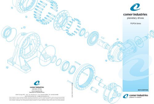
Comer Industries SpA<br />
Operating Unit Planetary Drives:<br />
www.comerindustries.com - info@comerindustries.com<br />
CIADV PD<strong>08</strong><strong>10</strong> PG/PGA SERIES<br />
<strong>08</strong>/<strong>10</strong> <strong>EDITION</strong>
Certificazione ATEX ATEX Certification 1<br />
L'azienda The company Das unternehmen La société La empresa A empresa 2<br />
Il prodotto The product Das produkt Le produit El producto O produto 4<br />
Le applicazioni The applications Die einsatzbereiche Les applications Las aplicaciones As aplicações 6<br />
Caratteristiche<br />
tecniche<br />
Installazione<br />
manutenzione<br />
Technical<br />
characteristics<br />
Installation -<br />
maintenance<br />
Technische<br />
eigenschaften<br />
Caractéristiques<br />
techniques<br />
Características<br />
técnicas<br />
Einbau-wartung Installation - entretien Instalación –<br />
mantenimiento<br />
Características<br />
técnicas<br />
Instalação -<br />
manutenção<br />
Lubrificazione Lubrication Schmierung Lubrification Lubricación Lubrificação 42<br />
Layout Layout Layout Layout Layout Layout 60<br />
Designazione prodotto Product identification Produktbeschreibung Designation produit Designación producto Designação do<br />
produto<br />
Simbologia Legend Legende Symboles Símbolos Símbolos 64<br />
ACCESSORI ENTRATA/ INPUT FITTINGS<br />
ANTRIEBSBAUTEILE / ACCESSOIRES D'ENTREE<br />
ACCESORIOS DE ENTRADA / ACESSÓRIOS DE ENTRADA<br />
Freni modulari Modular brakes Bremsemodule Freins modulaires Frenos modulares Freios modulares 226<br />
Alberi entrata Input shafts Antriebswellen Arbres d’entrée Ejes de entrada Eixos de entrada 228<br />
Entrate dirette Direct inputs Standardantrieb Entrée directes Entradas directas Entradas diretas 232<br />
Predisposizioni motori<br />
idraulici<br />
Predisposizioni motori<br />
elettrici<br />
Predisposizioni per<br />
riduttori a vite senza<br />
fine<br />
INDICE / INDEX / INHALT / SOMMAIRE / INDICE / INDICE<br />
SCHEDE TECNICHE RIDUTTORI / PLANETARY GEARS TECHNICAL SHEETS<br />
TECHNISCHE DATENBLÄTTER GETRIEBE / FICHES TECHNIQUES REDUCTEURS<br />
FICHAS TECNICAS REDUCTORES / FICHAS TECNICAS REDUCTORES<br />
PG<br />
PGA<br />
Hydraulic motor<br />
couplings<br />
Electric motor<br />
couplings<br />
Worm gearbox<br />
adaptors<br />
Anbauvorrichtung fuer<br />
hydraulikmotore<br />
Anbauvorrichtung für<br />
elektromotore<br />
Anschluss für<br />
schneckengetriebe<br />
i kNm<br />
Adaptations pour<br />
moteurs hydraulique<br />
Adaptations pour<br />
moteurs electriques<br />
Adaptation pour<br />
reducteurs a vis sans<br />
fin<br />
Acoplamientos para<br />
motores hidráulicos<br />
Acoplamientos para<br />
motores eléctricos<br />
Acoplamientos para<br />
reductores de tornillo<br />
sin fin<br />
Predisposições para<br />
motores hidráulicos<br />
Predisposições para<br />
motores elétricos<br />
Predisposições para<br />
redutores de rosca<br />
sem fim<br />
8<br />
36<br />
62<br />
39<br />
<strong>10</strong>0 3.55-3422 1.00 68<br />
160 3.55-3422 1.60 76<br />
250 3.77-2369 2.50 84<br />
500 3.77-1845 5.00 92<br />
700 3.66-2969 7.00 <strong>10</strong>0<br />
<strong>10</strong>00 3.55-2230 <strong>10</strong>.00 1<strong>08</strong><br />
1600 3.55-2230 16.00 116<br />
1800 13.00-1216 18.00 124<br />
2500 4.00-1774 25.00 132<br />
3000 14.20-1425 30.00 140<br />
3500 4.00-1290 35.00 148<br />
5000 4.00-1982 50.00 156<br />
6500 3.83-<strong>10</strong><strong>08</strong> 65.00 164<br />
9000 4.00-1623 90.00 172<br />
14000 3.69-7313 140.00 180<br />
18000 3.91-9793 180.00 188<br />
22000 3.68-8263 220.00 196<br />
33000 4.09-8522 330.00 204<br />
40000 3.83-5156 400.00 2<strong>10</strong><br />
55000 3.84-5571 550.00 216<br />
65000 3.84-5571 650.00 220<br />
225<br />
239<br />
243<br />
244
IT CERTIFICAZIONE ATEX EN<br />
ATEX CERTIFICATION<br />
Cer ti fi ca zio ne ATEX II 2 GD c k T4 per i ri dut to ri se rie<br />
PG/PGA di Pla ne tary Dri ves<br />
Comer Indu stries am plia la se rie di ri dut to ri PG/PGA di<br />
Pla ne tary Dri ves con la gam ma ATEX (da ATmo sphè res<br />
EXplo si bles), in con for mi tà con la Di ret ti va 94/9/CE che<br />
re go la men ta le ap pa rec chia tu re de sti na te al l’im pie go in<br />
zone a ri schio di esplo sio ne.<br />
I ri dut to ri se rie PG/PGA ATEX sono ido nei per ap pli ca zio -<br />
ni in aree con pre sen za di at mo sfe ra po ten zial men te<br />
esplo si va e con pre sen za di mi sce le gas so se e/o pol ve ri<br />
com bu sti bi li. La Di ret ti va eu ro pea 94/9/CE im po ne la cer ti -<br />
fi ca zio ne ATEX a tut ti i pro dot ti com mer cia liz za ti nel l’Unio -<br />
ne stes sa, in di pen den te men te dal lu o go di pro du zio ne e<br />
dal le nor ma ti ve in esso in vi go re, se in stal la ti in lu o ghi a ri -<br />
schio di esplo sio ne, con l’ec ce zio ne di al cu ni ap pa rec chi.<br />
I ri dut to ri pro get ta ti da Comer Indu stries per ap pli ca zio ne<br />
in am bien ti ATEX si di stin guo no per l’u ti liz zo di ma te ria li<br />
ido nei se con do le nor me di ri fe ri men to ed im pie ga no par ti<br />
spe cia li qua li anel li te nu ta olio esclu si va men te in Vi ton®;<br />
anel li pa ra o lio in Vi ton® con lab bro pa ra pol ve re e tap pi<br />
sfia to con val vo la a mol la; uti liz zo di olio e gras so sin te ti ci,<br />
pre sen za di ri le va to ri ade si vi ter mo sen si bi li, spes so ri li mi -<br />
ta ti del la ver ni cia tu ra e pre di spo si zio ne per col le ga men to<br />
di mes sa a ter ra.<br />
I ri dut to ri PG/PGA ATEX ven go no sot to po sti a pro ve spe -<br />
ci fi che se con do quan to pre vi sto dal le nor me e sono for ni ti<br />
com ple ti di spe ci fi co Ma nua le Istru zio ni e Di chia ra zio ne di<br />
con for mi tà se con do l’al le ga to VIII del la Di ret ti va 94/9/CE.<br />
I dati tec ni ci dei ri dut to ri ATEX sono in di ca ti sul ca ta lo go<br />
ge ne ra le dei Ri dut to ri se rie PG/PGA.<br />
ATEX II 2 GD c k T4 cer ti fi ca tion for Pla ne tary Dri ves<br />
se ries PG/PGA<br />
Comer Indu stries ex tends the PG/PGA Pla ne tary Dri ves<br />
se ries with the ATEX ran ge (from Atmo sphè res EXplo si -<br />
bles) in ac cor dan ce with Di rec ti ve 94/9/EC re gu la ting<br />
equip ment in ten ded for use in are as at risk of ex plo sion.<br />
Pla ne tary Dri ves se ries PG/PGA are su i ta ble for ap pli ca -<br />
tion in are as with po ten tially ex plo si ve at mo sphe res and in<br />
are as with pre sen ce of gas mix tu res and / or combu sti ble<br />
dusts The Eu ro pe an Di rec ti ve ATEX (from French words:<br />
Atmo sphè res EXplo si bles, po ten tially ex plo si ve at mo -<br />
sphe re) 94/9/EC re qui res cer ti fi ca tion for all pro ducts mar -<br />
ke ted in the EU, re gar dless of pia ce of pro duc tion and lo -<br />
cai re gu la tions in for ce, when in stal led in are as at risk of<br />
ex plo sion, with the ex cep tion of some equip ment.<br />
Comer Indu stries spe ci fi cally de si gned dri ves for use in<br />
ATEX en vi ron ments dif fer from nor mal se ries ma inly for<br />
the use of su i ta ble ma te rials as re que sted by the EU stan -<br />
dards such as oil seal ring in Vi ton ®; Vi ton ® shaft se als<br />
with dust pro tec tion; bre at her plugs with val ve; use of<br />
synthe tic oil and gre a se; pre sen ce of heat-sen si ti ve ad he -<br />
si ve de tec tors; re du ced pa int thic kness; ar ran ge ment for<br />
gro un ding.<br />
PG/PGA ATEX dri ves are sub jec ted to spe ci fic tests in ac -<br />
cor dan ce with thè a.m. norms and are pro vi ded with an in -<br />
struc tion ma nual in Ita lian and English lan gua ge, in clu ding<br />
a De cla ra tion of Con for mity, as re que sted by at tac hment<br />
VIII, Di rec ti ve 94/9/EC.<br />
Tec hni cal data are in di ca ted on the ge ne rai ca ta lo gue<br />
PG/PGA se ries.<br />
1
IT L’AZIENDA EN THE COMPANY DE DAS UNTERNEHMEN<br />
Co mer Indu stries è un ’or ga niz za zio ne<br />
glo ba le di in ge gne ria e tec no lo gia, le a -<br />
der nel la pro get ta zio ne e pro du zio ne<br />
di si ste mi avan za ti di in ge gne ria e so -<br />
lu zio ni di mec ca tro ni ca per la tra smis -<br />
sio ne di po ten za, de sti na ti ai prin ci pa li<br />
co strut to ri mon dia li di mac chi ne ope ra -<br />
tri ci agri co le e in du stria li.<br />
All’in ter no di Co mer Indu stries l’Uni tà<br />
Ope ra ti va Pla ne tary Dri ves è quel la<br />
de di ca ta alla pro get ta zio ne, pro du zio -<br />
ne e com mer cia liz za zio ne di ri dut to ri<br />
epi ciclo i da li mo du la ri, ri dut to ri ru o ta e<br />
ri dut to ri per ro ta zio ne de sti na ti al l’im -<br />
pie go su mac chi ne ope ra tri ci mo bi li e<br />
im pian ti fis si in du stria li.<br />
Le tra smis sio ni Pla ne tary Dri ves sono<br />
al ta men te per so na liz za te e l’am pia co -<br />
no scen za del le ap pli ca zio ni in du stria li<br />
uni ta al l’e le va ta ca pa ci tà pro get tua le<br />
con sen to no di ri spon de re alle esi gen ze<br />
del clien te con l’in no va zio ne con ti nua,<br />
la qua li tà e l’of fer ta di un ser vi zio com -<br />
ple to.<br />
Certificazione TÜV del Sistema di Qualità<br />
Comer Industries - Planetary Drives.<br />
Certificazione TÜV del Sistema di<br />
Gestione Ambientale Comer Industries<br />
- Planetary Drives.<br />
2<br />
Comer In dus tries is a global en gi neer -<br />
ing and tech nol ogy com pany and a<br />
leader in the de sign and man u fac ture<br />
of ad vanced en gi neer ing and sys tems<br />
and mechatronic so lu tions for power<br />
trans mis sion de vel oped for the world's<br />
main ag ri cul tural and in dus trial ma chin -<br />
ery man u fac tur ers.<br />
Comer In dus tries' Plan e tary Drives Op -<br />
er at ing Unit de signs, man u fac tures and<br />
mar kets mod u lar plan e tary drives,<br />
wheel drive gear units and plan e tary<br />
slew ing drives for in stal la tion on mo bile<br />
op er at ing ma chin ery and sta tion ary in -<br />
dus trial equip ment.<br />
The plan e tary drive trans mis sions are<br />
highly customised and, thanks to ex -<br />
ten sive knowl edge of in dus trial ap pli ca -<br />
tions com bined with cut ting-edge de -<br />
sign ex per tise, Comer In dus tries meets<br />
all cus tomer re quire ments through con -<br />
stant in no va tion, qual ity and com pre -<br />
hen sive ser vice.<br />
TÜV Cer tif i ca tion of the Comer In dus -<br />
tries - Plan e tary Drives Qual ity Sys tem.<br />
TÜV Cer tif i ca tion of the Comer In dus -<br />
tries - Plan e tary Drives En vi ron men tal<br />
Man age ment Sys tem.<br />
Certificazione TÜV del Sistema di Qualità<br />
Co mer Indu stries - Pla ne tary Dri ves<br />
TÜV Certification of the Co mer Indu stries -<br />
Pla ne tary Dri ves Quality System<br />
TÜV Wiederbeurkundigung des<br />
Qualitätsystems Co mer Indu stries -<br />
Pla ne tary Dri ves<br />
Co mer Indu stries ist eine glo ba le<br />
Engi ne e ring- und Tec hno lo gie-Orga -<br />
ni sa tion und ist Marktführer in der<br />
Entwic klung und Fer ti gung fortschrit -<br />
tli cher Engi ne e ring- und Me cha tro -<br />
nik lö sun gen für die Le i stungsüber tra -<br />
gung, die für die wic htig sten Her stel -<br />
ler von Lan dwirtschafts- und Indu -<br />
strie ma schi nen be stimmt sind.<br />
In Co mer Indu stries ist die Abte i lung<br />
für Pla ne ten ge trie be der Entwic -<br />
klung, Fer ti gung und Ver mar ktung<br />
von mo du la ren Pla ne ten ge trie ben,<br />
Ra dun ter set zun gen und Ro ta tion -<br />
sun ter set zun gen für den Ein satz in<br />
ver fah rba ren und festste hen den<br />
Indu strie ma schi nen ge wid met.<br />
Die Pla ne ten ge trie be wer den kun de -<br />
nin di vi du ell ge fer tigt und dank der<br />
gro ßen Erfah rung bei den Indu strie -<br />
an wen dun gen so wie der op ti ma len<br />
Entwic klungska pa zität kann den Kun -<br />
de nansprüchen mit kon ti nu ier li cher<br />
Inno va tion und ei nem kom plet ten Ser -<br />
vi ce-Ange bot entspro chen wer den.<br />
TÜV-Be sche i ni gung des Qua litätsma<br />
na ge mentsystems Co mer Indu -<br />
stries - Pla ne ten ge trie be.<br />
TÜV-Bescheinigung des Umweltmanagementsystems<br />
Comer Industries<br />
– Planetary Drives.<br />
Certificazione TÜV del Sistema di Gestione<br />
Ambientale Co mer Indu stries - Pla ne tary<br />
Dri ves<br />
TÜV Certification of the Co mer Indu stries -<br />
Pla ne tary Dri ves Environmental<br />
Management System<br />
TÜV-Bescheinigung des<br />
Umweltmanagementsystems Comer<br />
Industries – Planetary Drives
LA SOCIETE FR LA EMPRESA ES<br />
A EMPRESA PT<br />
Co mer Indu stries est une or ga ni sa tion<br />
glo ba le d'in gé nie rie et de tec hno lo gi -<br />
que, le a der dans la con cep tion et la<br />
pro duc tion de systè mes avan cés d'in -<br />
gé nie rie et de so lu tions de mé ca tro ni -<br />
que pour la tran smis sion de pu is san ce,<br />
de sti nés aux prin ci pa ux con struc te urs<br />
mon dia ux de ma chi nes agricoles et<br />
industrielles.<br />
Au sein de Co mer Indu stries, l'Uni té<br />
Opé ra ti ve Pla ne tary Dri ve est cel le qui<br />
s'oc cu pe de la con cep tion, de pro duc -<br />
tion et de la com mer cia li sa tion de ré -<br />
duc te urs épicycloï da ux mo du la i res, de<br />
ré duc te urs de roue et de ré duc te urs de<br />
ro ta tion de sti nés à une uti li sa tion sur<br />
des ma chi nes mo bi les ou sur des in -<br />
stal la tions fi xes in du striel les. Les tran -<br />
smis sions Pla ne tary Dri ves sont ha u te -<br />
ment per son na li sa bles et la con na is -<br />
san ce éten due des ap pli ca tions in du -<br />
striel les al li ée à de ha u tes ca pa ci tés de<br />
con cep tion per met tent de ré pon dre<br />
aux exi gen ces des clients à tra vers de<br />
con stan tes in no va tions, la qua li té et<br />
l'of fre d'un ser vi ce com plet.<br />
Certification TÜV du Système<br />
d'Assurance Qualité Cormer Industries<br />
- Planetary Drives.<br />
Certification TÜV du Système de<br />
gestion environnementale Comer<br />
Industries – Planetary Drives.<br />
Co mer Indu stries es una or ga ni za ci ón<br />
glo bal de in ge nier ía y tec no log ía, líder<br />
en el di se ño y pro duc ci ón de si ste mas<br />
avan za dos de in ge nier ía y so lu cio nes<br />
de me ca tró ni ca para la tran smi si ón de<br />
po ten cia, de sar rol la dos para los prin ci -<br />
pa les con struc to res mun dia les de má -<br />
qui nas agríco las e in du stria les.<br />
La Uni dad Ope ra ti va Pla ne tary Dri ves<br />
de Co mer Indu stries di se ña, pro du ce y<br />
co mer cia li za re duc to res epi ci clo i da les<br />
mo du la res, re duc to res de ru e da y re -<br />
duc to res para ro ta ci ón de sti na dos al<br />
em pleo en má qui nas mó vi les y en in -<br />
sta la cio nes in du stria les fi jas.Las tran -<br />
smi sio nes Pla ne tary Dri ves son muy<br />
per so na li za das y, gra cias al gran co -<br />
no ci mien to de las apli ca cio nes in du -<br />
stria les jun to con la ele va da ca pa ci dad<br />
de di se ño, Co mer Indu stries pu e de sa -<br />
ti sfa cer las exi gen cias del Clien te a<br />
tra vés de la in no va ci ón con ti nua, la<br />
ca li dad y brin dan do un ser vi cio com -<br />
ple to.<br />
Sistema de Calidad de Comer In dus -<br />
tries - Plan e tary Drives certificado por<br />
TÜV.<br />
Certificación TÜV del Sistema de<br />
Gestión Ambiental Comer Industries –<br />
Planetary Drives.<br />
Certification TÜV du Système de Qualité<br />
Co mer Indu stries - Pla ne tary Dri ves<br />
Sistema de Calidad de Comer Industries -<br />
Planetary Drives certificado por TÜV<br />
Certificação TÜV do Sistema de Qualidade<br />
da Comer Industries - Planetary Drives<br />
A Co mer Indu stries é uma com pan hia<br />
glo bal de en gen ha ria e tec no lo gia,<br />
líder no de sen vol vi men to e pro du ção<br />
de si ste mas avan ça dos de en gen ha ria<br />
e de so luç ões de me catrôni ca para a<br />
tran smis são de potência, vol ta dos aos<br />
prin ci pa is fa bri can tes mun dia is de má -<br />
qui nas agríco las e in du stria is.<br />
Den tro da Co mer Indu stries, a Uni da -<br />
de Ope ra ti va Pla ne tary Dri ves é a de -<br />
di ca da ao pro je to, pro du ção e co mer -<br />
cia li za ção de re du to res pla ne tá rios<br />
mo du la res, re du to res de roda e re du -<br />
to res para ro ta ção de sti na dos ao em -<br />
pre go em má qui nas ope ra tri zes mó ve -<br />
is e em equi pa men tos in du stria is fi xos.<br />
As tran smi ssões Pla ne tary Dri ves são<br />
al ta men te per so na li za das e o am plo<br />
con he ci men to das apli caç ões in du -<br />
stria is, alia do à ele va da ca pa ci da de de<br />
pro je to, per mi tem re spon der às<br />
exigências do clien te com a ino va ção<br />
contínua, a qua li da de e a ofer ta de um<br />
ser vi ço com ple to.<br />
Certificação TÜV do Sistema de<br />
Qualidade da Comer In dus tries - Plan -<br />
e tary Drives.<br />
Certificação TÜV do Sistema de<br />
Gestão Ambiental Comer Industries –<br />
Planetary Drives.<br />
Certification TÜV du Système de gestion<br />
environnementale Comer Industries –<br />
Planetary Drives<br />
Certificación TÜV del Sistema de Gestión<br />
Ambiental Comer Industries – Planetary<br />
Drives<br />
Certificação TÜV do Sistema de Gestão<br />
Ambiental Comer Industries – Planetary<br />
Drives<br />
3
IT IL PRODOTTO EN THE PRODUCT DE<br />
DAS PRODUKT<br />
L’utilizzo del ri dut to re epi ci clo i da le per la<br />
tra smis sio ne di po ten za è una ri spo sta mo -<br />
der na alle esi gen ze di in gom bri li mi ta ti, di<br />
sem pli ci tà co strut ti va e di af fi da bi li tà per<br />
l’utilizzatore.<br />
I ri dut to ri epi ci clo i da li PG/PGA sono co sti tu -<br />
i ti da ac cia io per il 60% e ghi sa per il 35%<br />
cir ca e in per cen tua le mi no re da al lu mi nio,<br />
rame, gom ma e ot to ne. Tali per cen tua li va -<br />
ria no a se con da del le configurazioni del<br />
prodotto.<br />
La fa mi glia di ri dut to ri epi ci clo i da li PG è of -<br />
fer ta al mer ca to in 21 gran dez ze di base,<br />
se le zio na te in fun zio ne dei mo men ti tor -<br />
cen ti che pos so no es se re tra smes si<br />
all’albero di usci ta, che van no da 0.5 kNm<br />
fino a 65 kNm.<br />
La mo du la ri tà del pro dot to Planetary Dri ves<br />
per met te l’ac cop pia men to ai ri dut to ri epi ci -<br />
clo i da li di cop pie co ni che, ri dut to ri vite sen -<br />
za fine, fre ni idra u li ci, di ver si tipi di al be ri di<br />
in gres so, non chè di flan ge per l’ac cop pia -<br />
men to di ret to a mo to ri idra u li ci o elet tri ci.<br />
Un al tro gran de van tag gio de ri van te dal la<br />
mo du la ri tà dei ri dut to ri epi ci clo i da li è la pos -<br />
si bi li tà del mon tag gio in se rie di sta di di dif -<br />
fe ren ti gran dez ze, in modo da ot te ne re una<br />
va stis si ma gam ma di rap por ti di ri du zio ne.<br />
La gam ma di pro dot ti Pla ne tray Dri ves of fre<br />
rap por ti di ri du zio ne da 3:1 a 7:1 per i ri dut -<br />
to ri a sin go lo sta dio fino a <strong>10</strong>.000:1 e ol tre<br />
per i ri dut to ri a 5 sta di di ri du zio ne.<br />
Le di ver se op zio ni di al be ro e flan gia tu ra in<br />
usci ta sem pli fi ca no l’installazione del ri dut -<br />
to re su ap pli ca zio ni mo bi li e im pian ti fis si in -<br />
du stria li.<br />
La for ni tu ra stan dard del pro dot to non pre -<br />
ve de la ver ni cia tu ra a fi ni re. Co mer Indu -<br />
stries rac co man da l’u ti liz zo di ver ni ci a bas -<br />
so impatto ambientale.<br />
4<br />
The use of plan e tary gear units in the field<br />
of power trans mis sion is the mod ern an -<br />
swer to the de mand for com pact ness, con -<br />
struc tive sim plic ity and prod uct re li abil ity.<br />
PG/PGA pla ne tary dri ves are made of 60%<br />
ste el, abo ut 35% cast iron and a lo wer per -<br />
cen ta ge of alu mi nium, cop per, rub ber and<br />
brass. The se per cen ta ges vary de pen ding<br />
on the pro duct con fi gu ra tions.<br />
PG plan e tary gear units are di vided into 21<br />
ba sic groups de pend ing on the dif fer ent<br />
torques that are to be trans mit ted to the<br />
out put shaft, which can vary from 0.5 to 65<br />
kNm.<br />
In fact, the Planetary Drives prod uct mod u -<br />
lar con struc tion per mits the cou pling of<br />
bevel gears, worm gears, hy drau lic brakes<br />
and a va ri ety of in put shafts to the plan e tary<br />
units, as well as pro vid ing for a wide choise<br />
of cou pling flanges for hy drau lic or elec tric<br />
mo tors.<br />
An other ad van tage of the plan e tary drives'<br />
mod u lar con struc tion is that var i ous stages,<br />
in dif fer ent sizes, can be mounted in se ries<br />
to of fer a wide range of re duc tion ratios.<br />
Plan e tary Drive re duc tion ra tios range from<br />
3:1 to 7:1 on sin gle-stage drives up to<br />
<strong>10</strong>,000:1 and more on 5-stage drives.<br />
The wide se lec tion of out put shafts and<br />
flanges sim pli fies the re duc tion unit mount -<br />
ing op er a tion on in dus trial ma chin ery or<br />
plants.<br />
Stan dard supply of the pro duct does not in -<br />
clu de pa in ting upon com ple tion. Co mer<br />
Indu stries re com mends using eco-friendly<br />
paints.<br />
Im Vergleich zum Stirnradgetriebe, bei<br />
dem nur ein Zahn die Kräfte überträgt,<br />
wird das Mo ment am Zentralrad des<br />
Planetengetriebes auf drei Zahneingriffe<br />
aufgeteilt. Diese Konstruktion fuehrt zu<br />
kleinen Getriebeabmessungen, kompakter<br />
Bauweise und einem geringen Eigengewicht.<br />
Die Pla ne ten ge trie be PG/PGA be ste hen<br />
zu 60% aus Stahl, zu ca. 35% aus Gus se -<br />
i sen und aus ge rin ge ren Men gen Alu mi -<br />
nium, Kup fer, Gum mi und Mes sing. Die se<br />
pro zen tu el len Ante i le va riie ren je nach<br />
Kon fi gu ra tion des Produkts.<br />
Die Pla ne ten ge trie be der Se rie PG wer -<br />
den in 21 Grund grö ßen mit Ab triebs dreh -<br />
mo men ten von 0.5 kNm bis zu 65 kNm<br />
her ge stellt.<br />
Die mo du la re Kon struk tion der Planetary<br />
Dri ves-Pro duk te er la ubt die Kom bi na tion<br />
mit Ke gel rad ge trie ben, Schnec ken ge trie -<br />
ben, hydra u li schen Brem sen, un ter schie -<br />
dli chen Ausführun gen von Antrieb swel len<br />
und Mo tor flan schen für hydra u li sche und<br />
elek tri sche Motore.<br />
Der Antrieb ist mit al len ga en gi gen Hydra u -<br />
lik mo to ren, aber auch mit fre iem Wel le nen -<br />
de oder Flansch für den Antrieb durch Elek -<br />
to mo to re zu re a li sie ren.<br />
Im Hydra u lik be trieb wird eine war tungsfre -<br />
ie und ger äu schar me Fe der druck - La mel -<br />
len brem se als Hal te brem se eingesetzt.<br />
Die ver fu eg ba ren For men hin sicht lich der<br />
Wel len und Flan sche des Ab triebs er lau -<br />
ben den Ein bau der Ge trie be in di ver sen<br />
mo bi len und sta tio nae ren Applikationen.<br />
Die Stan dar da usführung des Pro dukts<br />
wird ohne Schlus san strich ge lie fert. Co -<br />
mer Indu stries em pfiehlt den Ge bra uch<br />
von um weltfre un dli chen Lac ken.
LE PRODUIT FR EL PRODUCTO ES<br />
O PRODUTO PT<br />
L’utilisation du réducteur planétaire pour la<br />
trans mis sion de puis sance est une so lu tion<br />
moderne répondant aux exigences de di -<br />
men sions réduites, de simplicité dans la<br />
con struc tion et de fiabilité pour l’utilisateur.<br />
Les réducteurs épicycloïdaux PG/PGA sont<br />
réalisés à 60% en acier et à 35% environ<br />
en fonte, avec un pourcentage minime<br />
d'aluminium, de cuivre, de laiton et de<br />
caoutchouc. Ces pourcentages varient<br />
selon les différentes configurations du<br />
produit.<br />
La fa mille de ré duc teurs pla né tai res PG se<br />
pré sente sur le mar ché avec 21 ty pes de<br />
base, sé lec tion nés en fonc tion des cou ples<br />
trans mis si bles sur l’arbre de sortie qui vont<br />
de 0.5 à 65 kNm.<br />
La con struc tion modulaire du produit<br />
Planetary Drives permet d'accoupler les<br />
réducteurs planétaires avec des cou ples<br />
coniques, des vis sans fin, des freins<br />
hydrauliques ou bien avec di vers types<br />
d’arbres d' entrée, ainsi qu’avec des brides<br />
pour la fix a tion directe sur moteurs<br />
hydrauliques ou électriques.<br />
La possibilité de monter en série des<br />
étages de différents rapports permettant<br />
d’obtenir une très vaste gamme de rapports<br />
de réduction (de 3:1 à 7:1 pour les<br />
réducteurs monoétagés et jusqu’à <strong>10</strong>.000:1<br />
et plus pour les réducteurs à 5 étages de<br />
réduction) est un autre grand avan tage<br />
résultant de la con cep tion modulaire des<br />
réducteurs Planetray Drives.<br />
La pos si bi li té de dis po ser de plu sieurs op -<br />
tions en ce qui concerne l’arbre et le bri -<br />
dage côté sortie du ré duc teur sim plifie le<br />
mon tage de ce der nier sur les ma chi nes ou<br />
sur les equi pe ments in dus triels.<br />
La fourniture standard du produit ne prévoit<br />
pas la peinture de finition. Comer Industries<br />
recommande l'utilisation de peintures à<br />
faible impact environnemental.<br />
La uti li za ci ón del re duc tor epi ci clo i dal para<br />
la tra smi si ón de po ten cia es una so lu ci ón<br />
mo der na ante las exi gen cias de espa cios<br />
li mi ta dos, de sen cil lez con struc ti va y de<br />
con fia bi li dad para el uti li za dor.<br />
Los reductores epicicloidales PG/PGA<br />
están constituidos por un 60% de acero,<br />
aproximadamente, un 35% de fundición y,<br />
en menor porcentaje, por aluminio, cobre,<br />
caucho y latón. Estos porcentajes varían<br />
según las configuraciones del producto.<br />
La fa mi lia de re duc to res epi ci clo i da les PG<br />
está com pu e sta por 21 gru pos bá si cos, se -<br />
lec cio na dos en fun ci ón de los mo men tos<br />
de tor si ón que se pu e den tran smi tir al eje<br />
de sa li da, que van de sde 0.5 kNm ha sta<br />
65 kNm.<br />
La con struc ci ón mo du lar del pro duc to Pla -<br />
ne tary Dri ves per mi te aco plar a los re duc -<br />
to res epi ci clo i da les de pa res có ni cos, re -<br />
duc to res de tor nil lo sin fin, fre nos hi drá u li -<br />
cos, di stin tos ti pos de ejes de en tra da, así<br />
como bri das para el aco pla mien to di rec to a<br />
mo to res hi drá u li cos o eléc tri cos.<br />
Otra gran ven ta ja ofre ci da por la con struc -<br />
ci ón mo du lar de los re duc to res epi ci clo i da -<br />
les es la po si bi li dad del mon ta je en se rie<br />
de eta pas con di fe ren te ma gni tud, para po -<br />
der ob te ner una va sta gama de re la cio nes<br />
de re duc ci ón. La gama de pro duc tos Pla -<br />
ne tary Dri ves ofre ce re la cio nes de re duc ci -<br />
ón de 3:1 a 7:1 para los re duc to res con<br />
una sola eta pa ha sta <strong>10</strong>.000:1 y más para<br />
los re duc to res con 5 eta pas de re duc ci ón.<br />
Las di stin tas op cio nes de eje y de em bri da -<br />
do en la sa li da sim pli fi can la in sta la ci ón del<br />
re duc tor en apli ca cio nes mó vi les y en in -<br />
sta la cio nes in du stria les fijas.<br />
El suministro estándar del producto no<br />
prevé la pintura de terminación. Comer<br />
Industries recomienda usar pinturas de<br />
bajo impacto ambiental.<br />
A uti li za ção de re du to res pla ne tá rios para<br />
a tran smis são de potência é uma re spo sta<br />
mo der na às exigências de com pa ci da de,<br />
sim pli ci da de de con stru ção e con fia bi li da -<br />
de para o usu á rio fi nal.<br />
Os redutores planetários PG/PGA estão<br />
constituídos de 60% de aço, aproximadamente,<br />
35% de ferro fundido e em<br />
menor percentagem, por alumínio, cobre,<br />
borracha e latão. Estes percentuais variam<br />
de acordo às configurações do produto.<br />
A fam ília de re du to res pla ne tá rios PG é<br />
ofe re ci da ao mer ca do em 21 ta man hos bá -<br />
si cos, se le cio na dos em fun ção dos mo -<br />
men tos de tor ção que po dem ser tran smi ti -<br />
dos ao eixo de saí da, que vão de 0,5 kNm<br />
a 65 kNm.<br />
A mo du la ri da de do pro du to Pla ne tary Dri -<br />
ves per mi te o aco pla men to a re du to res<br />
pla ne tá rios de pa res côni cos, re du to res de<br />
ro sca sem fim, fre ios hi drá u li cos, vá rios ti -<br />
pos de ei xos de en tra da, as sim como a se -<br />
le ção de flan ges para o aco pla men to di re to<br />
a mo to res hi drá u li cos ou elé tri cos.<br />
Uma ou tra gran de van ta gem pro por cio na -<br />
da pela mo du la ri da de dos re du to res pla ne -<br />
tá rios é a pos si bi li da de da mon ta gem em<br />
sé rie de está gios de di fe ren tes ta man hos,<br />
per mi tin do a ob ten ção de uma gama ex tre -<br />
ma men te am pla de re laç ões de re du ção.<br />
A gama de pro du tos Pla ne tary Dri ves ofe -<br />
re ce re laç ões de re du ção que vão de 3:1 a<br />
7:1 para re du to res de um está gio, até<br />
<strong>10</strong>.000:1 e aci ma para uni da des com 5<br />
está gios de redução.<br />
As di fe ren tes op ções de ei xos e flan ges de<br />
saí da sim pli fi cam a in sta la ção do re du tor<br />
em apli caç ões mó ve is e equi pa men tos in -<br />
du stria is fixos.<br />
O fornecimento padronizado do produto<br />
não prevê a pintura de acabamento.<br />
Comer Industries recomenda a utilização<br />
de pinturas de baixo impacto ambiental.<br />
5
IT LE APPLICAZIONI EN THE APPLICATIONS DE DIE EINSATZBEREICHE<br />
Dai pri mi im pie ghi li mi ta ti so prat tut to alle<br />
mac chi ne mo vi men to ter ra, Co mer Indu -<br />
stries ha este so ed evo lu to le pos si bi li tà<br />
ap pli ca ti ve nel set to re in du stria le. Sem pre<br />
più fre quen ti sono le ap pli ca zio ni in im pian -<br />
ti chi mi ci, mac chi ne uten si li, mac chi ne la -<br />
vo ra zio ne mar mo, si ste mi di tra spor to e<br />
sol le va men to, im pian ti alimentari ed eco logici<br />
e macchine mobili in generale.<br />
FR<br />
De pu is les pre mi è res ap pli ca tions qui se li -<br />
mi ta ient prin ci pa le ment aux en gins des tra -<br />
va ux pu blics, Co mer Indu stries a éten du et<br />
dé ve lop pé les pos si bi li tés d’em ploi dans le<br />
do ma i ne in du striel.<br />
Les ap pli ca tions sont ma in te nant de plus<br />
en plus fré quen tes dans les com ple xes chi -<br />
mi ques, ali men ta i res et éco lo gi ques ain si<br />
que sur les ma chi nes ou tils, les ma chi nes<br />
pour le tra va il du mar bre, les di spo si tifs de<br />
tran sport et de re le va ge et to u tes les ma -<br />
chi nes mo bi les en gé né ral.<br />
6<br />
From when the first ap pli ca tions were im -<br />
ple men ted, li mi ted ma inly to earth-mo ving<br />
ma chi nery, Co mer Indu stries has ex ten ded<br />
and fully de ve lo ped ot her ap pli ca tions in<br />
the in du strial sec tor. The ran ge of ap pli ca -<br />
tions has now been ex ten ded to a wide va -<br />
riety of mo bi le ma chi nery, che mi cal plants,<br />
ma chi ne to ols, mar ble pro ces sing ma chi -<br />
nery, tran spor ta tion and ho i sting systems,<br />
in addition to the food and ecology<br />
industries.<br />
Applicazioni marine - comando eliche direzionali<br />
Marine applications - directional propellers control<br />
Schiffsbau - Drehwerk fuer Ruder- und Propellersteuerung<br />
Application marines - commande d'hélices<br />
Aplicaciones marinas - mando de hélices direccionales<br />
Aplicações marinhas - controle de hélices direcionais<br />
Pompe per calcestruzzo<br />
Concrete pumps<br />
Betonpumpe<br />
Pompes à beton<br />
Bombas para hormigón<br />
Bombas para concreto<br />
Autogru<br />
Off-road mobile cranes<br />
Autokraene<br />
Grues mobiles<br />
Camión grúa<br />
Caminhões-guindaste<br />
A par tir de las pri me ras uti li za cio nes, li mi -<br />
ta das so bre to do a las má qui nas para el<br />
mo vi mien to de tier ra, Co mer Indu stries am -<br />
plió y de sar rol ló las po si bi li da des de apli ca -<br />
ci ón en el sec tor in du strial. Son cada vez<br />
más fre cu en tes las apli ca cio nes en las in -<br />
sta la cio nes quí mi cas, má qui nas her ra -<br />
mien tas, má qui nas para la ela bo ra ci ón del<br />
már mol, si ste mas de tran spor te y ele va ci -<br />
ón, in sta la cio nes alimenticias y ecológicas<br />
y máquinas móviles en general.<br />
Carri miscelatori orizzontali<br />
Horizontal feed mixers<br />
Horizontal-Futtermischwagen<br />
Chariots mélangeurs horizontaux<br />
Carros mezcladores horizontales<br />
Carros misturadores horizontais<br />
Gru e sistemi di sollevamento<br />
Cranes and hoisting systems<br />
Kraene und Hubsysteme<br />
Grues et systèmes de leverage<br />
Grúas y sistemas de elevación<br />
Guindastes e sistemas de elevação<br />
Generatori eolici<br />
Wind power generators<br />
Windkraftanlagen<br />
Eoliennes<br />
Generadores eólicos<br />
Geradores eólicos<br />
Seit den er sten Anwen dun gen, die sich ha -<br />
uptsächlich auf Erdbe we gun gsam schi nen<br />
beschränkten, hat Co mer Indu stries die<br />
Anwen dungsmö glic hke i ten in ständig er -<br />
we i tert. Immer öf ter wer den die Pla ne ten -<br />
ge trie be auch in in du striel len Anwen dun -<br />
gen, wie För der-und Hubsyste men, Kra -<br />
nan la gen, im Schiffsbau, in der Offsho re-<br />
Tec hnik, Stah lve rar be i tung, Anla gen der<br />
Che mie, im Be re ich al ter na ti ver Ener gien,<br />
Umwel ttec hnik und der Nah rungsmit tel tec -<br />
hno lo gie eingesetzt, um nur einige<br />
Schwerpunkte aufzuzeigen.<br />
LES APPLICATIONS ES LAS APLICACIONES PT AS APLICAÇÕES<br />
A par tir das pri me i ras apli caç ões li mi ta das<br />
prin ci pal men te às má qui nas de ter ra pla na -<br />
gem, a Co mer Indu stries esten deu e evo lu -<br />
iu as pos si bi li da des de apli ca ção no se tor<br />
in du strial. São cada vez mais freq üen tes<br />
as apli caç ões em plan tas quí mi cas, má qui -<br />
nas ope ra tri zes, má qui nas de pro ces sa -<br />
men to de már mo re, si ste mas de tran spor te<br />
e ele va ção, equi pa men tos nos setores<br />
alimentar e ecológico e máquinas móveis<br />
em geral.
LE APPLICAZIONI<br />
IT EN<br />
IT THE APPLICATIONS EN DIE EINSATZBEREICHE DE DE<br />
LES LE APPLICATIONS PRODUIT FR LAS APLICACIONES ES AS APLICAÇÕES PT<br />
Carri miscelatori verticali<br />
Vertical feed mixers<br />
Vertikal-Futtermischwagen<br />
Chariots mélangeurs verticaux<br />
Carros mezcladores verticales<br />
Carros misturadores verticais<br />
Macchine enologiche, presse per uva<br />
Wine-making machines, grape presses<br />
Weinherstellung - Pressen<br />
Machines viticoles, pressoirs à raisin<br />
Máquinas enológicas, prensas para uva<br />
Máquinas enológicas, prensas para uva<br />
Gru gommate e cingolate<br />
Wheeled and tracked cranes<br />
Mobilkraene<br />
Grues sur pneumatiques et sur chenilles<br />
Grúas sobre neumáticos y de orugas<br />
Guindastes sobre rodas e sobre esteiras<br />
Trattamento acque<br />
Water treatment<br />
Wasseraufbereitung<br />
Traitement des eaux<br />
Tratamiento de aguas<br />
Tratamento de água<br />
Giostre<br />
Amusement park rides<br />
Vergnuegungseinrichtungen<br />
Manèges<br />
Carruseles<br />
Brinquedos de parques de diversão<br />
Gru per edilizia<br />
Tower cranes<br />
Turmkraene<br />
Grues de le secteur du bâtiment<br />
Grúas para la construcción<br />
Guindastes torres<br />
Impianti fissi industriali<br />
Stationary industrial equipment<br />
Stationaere Industrieanlagen<br />
Installations industrielles fixes<br />
Instalaciones industriales fijas<br />
Equipamentos industriais fixos<br />
Impianti trasformazione ferro/acciaio<br />
Steel/iron processing equipments<br />
Anlagen der Stahlerzeugung<br />
Installations de transformation fer/acier<br />
Instalaciones para trasformar hierro/acero<br />
Equipamentos de transformação do ferro/aço<br />
7
CARATTERISTICHE<br />
TECHNICAL<br />
IT<br />
TECNICHE EN INFORMATION DE<br />
CARATTERISTICHE TECNICHE<br />
La conoscenza e l’esatta interpretazione<br />
dei dati riportati sul presente catalogo sono<br />
condizione indispensabile per la scelta e<br />
l’impiego corretto dei prodotti presentati.<br />
È importante quindi definire alcuni<br />
parametri caratteristici:<br />
RAPPORTO DI TRASMISSIONE i<br />
È il valore effettivo del rapporto tra la<br />
velocità di entrata n1 e la velocità di uscita<br />
n2.<br />
Viene indicato per ogni tipo di riduttore<br />
nella relativa scheda tecnica.<br />
VELOCITÀ MASSIMA IN ENTRATA<br />
n1max [min- 1 ]<br />
Rappresenta il valore massimo accettabile<br />
per ogni grandezza di riduttore, in<br />
condizioni di funzionamento intermittente.<br />
Per applicazioni in servizio continuo o per<br />
velocità superiori a quelle indicate, il<br />
Servizio Tecnico Commerciale Comer<br />
Industries è a disposizione per ulteriori<br />
chiarimenti.<br />
I valori della velocità massima in entrata<br />
per ogni tipo di riduttore sono illustrati nelle<br />
singole schede tecniche.<br />
RENDIMENTO<br />
Nella trasmissione epicicloidale, il<br />
rendimento è generalmente elevato,<br />
mediamente 0.97- 0.98 per ogni stadio di<br />
riduzione. Questo dato indicativo si riduce nel<br />
caso di funzionamenti a velocità elevate o nel<br />
caso di riduttori in versione angolare.<br />
COPPIA CONTINUA<br />
Mc [kNm]<br />
È quella coppia per cui il valore delle<br />
sollecitazioni sugli ingranaggi è pari al<br />
valore limite secondo le norme<br />
internazionali ISO 6336.<br />
Questo valore convenzionale corrisponde<br />
ad una durata di vita teorica illimitata degli<br />
ingranaggi, tenendo conto sia della<br />
sollecitazione a flessione che della<br />
resistenza superficiale del dente (pressione<br />
di Hertz).<br />
8<br />
TECHNICAL INFORMATION<br />
To properly select and implement our products,<br />
users must have complete knowledge<br />
of and correctly interpret the information<br />
provided in this catalogue.<br />
Thus, it's important to define some distinctive<br />
parameters, such as:<br />
REDUCTION RATIO i<br />
This is the ratio between input speed n1<br />
and output speed n2.<br />
It is provided for each drive shown on the<br />
relative technical sheet.<br />
MAXIMUM INPUT SPEED<br />
n1max [min -1 ]<br />
This is the maximum allowable speed for<br />
each size of drive under intermittent work<br />
conditions. For more information about<br />
continuous duty or higher speeds, please<br />
contact the Comer Industries Technical-Commercial<br />
Service Department.<br />
Maximum speed values for each type of<br />
planetary drive are illustrated on the single<br />
technical sheets.<br />
EFFICIENCY<br />
Efficiency is usually high in planetary transmissions:<br />
average values range between<br />
0.97 and 0.98 for each reduction stage.<br />
This approximate value decreases under<br />
high-speed conditions or in applications<br />
with bevel gears.<br />
CONTINUOUS TORQUE<br />
Mc [kNm]<br />
Continuous torque is the maximum value of<br />
the stress on the gears according to international<br />
standard ISO 6336.<br />
This conventional value corresponds to the<br />
unlimited theoretical duration of the gears,<br />
taking into account both the bending stress<br />
and the surface strength of the tooth (Hertz<br />
pressure).<br />
TECHNISCHE EIGENSCHAFTEN<br />
Die Kenntnis der Anforderung, sowie die<br />
korrekte Umsetzung der im Katalog<br />
gelieferten Daten sind Voraussetzung für<br />
die gezielte Auswahl und somit den<br />
erfolgreichen Einsatz des entsprechenden<br />
Produktes.<br />
Es ist deshalb wichtig, die folgenden<br />
Bestimmungsfaktoren festzulegen:<br />
ÜBERSETZUNG i<br />
Es handelt sich um den Quotienten aus<br />
Antriebsdrehzahl n1 und Abtriebsdrehzahl<br />
n2.<br />
Sie wird für jedes Getriebemodell im jeweiligen<br />
technischen Datenblatt angegeben.<br />
MAXIMAL ZULÄSSIGE<br />
ANTRIEBSDREHZAHL<br />
n1max [min -1 ]<br />
Ist die zulässige Höchstgeschwindigkeit für<br />
jedes Planetengetriebe im intermittierenden<br />
Betrieb.Im Dauerbetrieb mit Antriebsdrehzahlen,<br />
die die angegebenen Werte<br />
überschreiten, halten Sie bitte Rücksprache<br />
mit dem Kundenservice (Sales) von Comer<br />
Industries.<br />
Die Werte der zulässigen Eingangsdrehzahl<br />
sind für jedes Getriebemodell im technischen<br />
Datenblatt angegeben.<br />
WIRKUNGSRAD<br />
Der Wirkungsgrad des Planetengetriebes<br />
liegt pro Planetenstufe bei 98%; d.h. bei einem<br />
dreistufigem Getriebe n gesamt =<br />
0,98x0,98x0,98 = 94%. Dieser Anhaltswert<br />
nimmt beim Betrieb mit hohen Geschwindigkeiten<br />
sowie bei Getrieben in der<br />
Winkelausführung ab<br />
DAUERDREHMOMENT<br />
Mc [kNm]<br />
TECHNISCHE<br />
EIGENSCHAFTEN<br />
Dieser allgemein festgelegte Wert<br />
entspricht einer theoretisch unbegrenzten<br />
Lebensdauer der Zahnräder, wobei sowohl<br />
die Biegespannung als auch die zulässige<br />
Hertzsche Pressung auf die Zahnflankenoberfläche<br />
berücksichtigt werden.<br />
Es handelt sich um das Limit der Beanspruchung<br />
an die Verzahnung gemaess<br />
der Norm ISO 6336
CARACTERISTIQUES<br />
TECHNIQUES<br />
FR<br />
VITESSE MAXIMALE D’ENTREE<br />
n1max [min -1 ]<br />
Ce paramètre représente la vitesse maximale<br />
admise pour chaque taille de réducteur,<br />
en condition de fonctionnement intermittent.<br />
Pour des applications en service continu<br />
ou bien pour des vitesses supérieures<br />
à celles indiquées, le Service Technico-<br />
Commercial Comer Industries est à votre<br />
disposition pour toute information supplémentaire.<br />
Les valeurs de vitesse maximale en entrée<br />
sont indiquées sur la fiche technique de<br />
chaque type de réducteur.<br />
COUPLE CONTINU<br />
Mc [kNm]<br />
Il s'agit du couple auquel la valeur des sollicitations<br />
sur les engrenages est égale à la<br />
valeur limite selon les normes internationales<br />
ISO 6336.<br />
Cette valeur conventionnelle correspond à<br />
une durée de vie théorique illimitée des engrenages,<br />
en tenant compte aussi bien de<br />
la contrainte de flexion que de la résistance<br />
de la surface de la dent (pression de<br />
Hertz).<br />
CARACTERÍSTICAS<br />
TÉCNICAS<br />
ES<br />
CARACTERÍSTICAS<br />
TÉCNICAS<br />
CARACTERISTIQUES TECHNIQUES CARACTERÍSTICAS TÉCNICAS<br />
CARACTERÍSTICAS TÉCNICAS<br />
La connaissance et la bonne interprétation<br />
des données contenues dans le présent<br />
catalogue sont deux conditions indispensables<br />
qui permettent de choisir et d'utiliser<br />
correctement les produits présentés.<br />
El conocimiento y la correcta interpretación<br />
de los datos indicados en este catálogo<br />
son una condición indispensable para efectuar<br />
la mejor elección y utilización de los<br />
productos presentados.<br />
O conhecimento e a interpretação exata<br />
dos dados fornecidos neste catálogo são<br />
uma condição indispensável para a seleção<br />
e o emprego correto dos produtos<br />
apresentados<br />
Il est par conséquent important de définir un<br />
certains nombre de paramètres spécifiques:<br />
Por tanto es importante definir algunos parámetros<br />
característicos:<br />
É assim extremamente importante definir<br />
alguns parâmetros característicos:<br />
RAPPORT DE TRANSMISSION i RELACIÓN DE TRANSMISIÓN i RELAÇÃO DE TRANSMISSÃO i<br />
Il s'agit de la valeur effective du rapport entre<br />
la vitesse d'entrée n1 et la vitesse de<br />
sortie n2.<br />
Elle est indiquée sur la fiche technique de<br />
chaque type de réducteurs.<br />
Es el valor efectivo de la relación entre la<br />
velocidad de entrada n1 y la velocidad de<br />
salida n2.<br />
El valor para cada tipo de reductor se indica<br />
en la respectiva ficha técnica.<br />
É o valor efetivo da relação entre a velocidade<br />
de entrada n1 e a velocidade de saída<br />
n2.<br />
É indicado para cada tipo de redutor na respectiva<br />
ficha técnica.<br />
VELOCIDAD MÁXIMA DE ENTRADA<br />
n1máx. [min -1 ]<br />
Representa el valor máximo aceptable<br />
para cada dimensión de reductor, con funcionamiento<br />
intermitente. Para aplicaciones<br />
con servicio continuo o para velocidades<br />
superiores a aquellas indicadas, se<br />
aconseja ponerse en contacto con el Servicio<br />
Técnico-Comercial de Comer Industries.<br />
Los valores de la velocidad máxima de entrada<br />
para cada tipo de reductor se indican<br />
en las respectivas fichas técnicas.<br />
PT<br />
VELOCIDADE MÁXIMA DE ENTRADA<br />
n1max [min -1 ]<br />
Representa o valor máximo aceitável para<br />
cada tamanho de redutor, em condições<br />
de funcionamento intermitente. Para aplicações<br />
em serviço contínuo ou para velocidades<br />
maiores do que as indicadas, o Serviço<br />
Técnico Comercial da Comer Industries<br />
está à disposição dos clientes para<br />
fornecer mais esclarecimentos.<br />
Os valores da velocidade máxima de entrada<br />
para cada tipo de redutor são indicados<br />
nas respectivas fichas técnicas.<br />
RENDEMENT<br />
RENDIMIENTO<br />
RENDIMENTO<br />
Sur les transmissions épicycloïdales, le<br />
rendement est généralement élevé,<br />
0.97-0.98 en moyenne pour chaque étage<br />
de réduction. Cette donnée indicative peut<br />
être inférieure dans le cas d'un fonctionnement<br />
à haute vitesse ou dans le cas de réducteurs<br />
en version angulaire.<br />
En la transmisión epicicloidal, el rendimiento<br />
es generalmente elevado, entre<br />
0.97-0.98 para cada etapa de reducción.<br />
Este dato indicativo se reduce para el funcionamiento<br />
con elevadas velocidades o<br />
para aplicaciones con reductores cónicos.<br />
Na transmissão epicicloidal, o rendimento<br />
é geralmente elevado, em média 0.97-<br />
0.98 para cada estágio de redução. Este<br />
dado indicativo diminui no caso de funcionamentos<br />
com velocidade elevada ou no<br />
caso de redutores na versão angular.<br />
MOMENTO DE TORSIÓN CONTINUO<br />
Mc [kNm]<br />
Es el valor del momento para el cual el valor<br />
de las solicitaciones en los engranajes<br />
es igual al valor límite según las normas internacionales<br />
ISO 6336.<br />
Este valor convencional corresponde a un<br />
tiempo de vida teórico ilimitado de los engranajes,<br />
teniendo en cuenta la solicitación<br />
bajo flexión y la resistencia superficial del<br />
diente (presión de Hertz).<br />
TORQUE CONTÍNUO<br />
Mc [kNm]<br />
Representa o torque para o qual o valor<br />
das solicitações nas engrenagens corresponde<br />
ao valor limite segundo as normas<br />
internacionais ISO 6336.<br />
Este valor convencional corresponde a<br />
uma vida útil teórica ilimitada das engrenagens,<br />
considerando tanto a solicitação à<br />
flexão, como a resistência superficial do<br />
dente (pressão de Hertz).<br />
9
CARATTERISTICHE<br />
TECHNICAL<br />
IT<br />
TECNICHE EN INFORMATION DE<br />
Ai fini della scelta del riduttore questo valore<br />
va posto in riferimento alla COSTANTE DI<br />
DURATA nxh espressa nel Diagramma 1<br />
dove:<br />
n = velocità in uscita (min -1 )<br />
h = durata di funzionamento (ore).<br />
Per semplicità di consultazione, nella scheda<br />
tecnica di prodotto sono riportati i valori<br />
di Mc corrispondenti ad un valore n2xh prefissato.<br />
COPPIA MASSIMA<br />
Mmax [kNm]<br />
È il valore massimo di coppia che il riduttore<br />
può trasmettere per breve tempo senza<br />
che si verifichino danneggiamenti ai suoi<br />
componenti interni ed alla sua struttura.<br />
Tale valore deve essere considerato come<br />
una coppia massima dovuta a picchi o<br />
spunti di avviamento e mai come coppia di<br />
lavoro; il valore Mmax deve inoltre essere<br />
opportunamente valutato in quegli azionamenti<br />
che comportano un elevato numero<br />
di avviamenti o inversioni.<br />
Il valore Mmax è indicato nelle schede tecniche<br />
di prodotto.<br />
TEMPERATURA DI FUNZIONAMENTO<br />
Le temperature dell’olio a cui i riduttori possono<br />
funzionare sono quelle comprese tra<br />
-20°C e + 90°C. Temperature al di fuori di<br />
questa fascia possono essere accettate se<br />
si prevedono particolari accorgimenti relativi<br />
ai tipi di lubrificante e di guarnizioni utilizzati.<br />
Tali accorgimenti possono essere decisi<br />
caso per caso, d’accordo con il Servizio<br />
Tecnico-Commerciale Comer Industries.<br />
POTENZA TERMICA<br />
Pt [kW]<br />
È la potenza massima trasmissibile dal riduttore<br />
in funzionamento continuo con lubrificazione<br />
normale a sbattimento, senza<br />
che l’olio superi la temperatura di 90°C.<br />
I valori di Pt riportati nelle singole schede<br />
tecniche di prodotto sono valori massimi<br />
espressi alle seguenti condizioni di impiego:<br />
servizio continuo<br />
velocità n 1 = 1500 min -1<br />
<strong>10</strong><br />
For the purpose of selecting a drive, this<br />
value must be considered in relation to the<br />
DURATION CONSTANT nxh, as shown in<br />
Curve 1 where:<br />
n = output speed (min -1 )<br />
h = working time (hours)<br />
To make consultation easier, the Mc values<br />
corresponding to a fixed n2xh value are<br />
shown on the product technical sheets.<br />
MAXIMUM TORQUE<br />
Mmax [kNm]<br />
This is the maximum output torque that the<br />
drive can transmit over a brief time interval<br />
without damaging its internal components<br />
and structure. This value must be considered<br />
as the maximum output torque owing<br />
to working or start-up peaks and never as<br />
the continuous working torque. Mmax must<br />
also be carefully evaluated in those applications<br />
with a high number of start-ups or<br />
reversals.<br />
The Mmax value is shown on the single product<br />
technical cards.<br />
WORKING TEMPERATURE<br />
The working oil temperature of the drives<br />
should range between -20°C and +90°C.<br />
Temperatures falling outside this range<br />
might be tolerated only if special lubricants<br />
and gaskets are used. For further information,<br />
please contact the Comer Industries<br />
Technical-Commercial Service Department.<br />
THERMAL POWER<br />
Pt [kW]<br />
The thermal power is the maximum power<br />
the drive can transmit under continuous<br />
duty with normal turbulence lubrication and<br />
without exceeding an oil temperature of<br />
90°C.<br />
The Pt values shown on the single product<br />
technical sheet indicate the maximum values<br />
under the following duty conditions:<br />
continuous duty<br />
speed n 1 = 1500 min -1<br />
TECHNISCHE<br />
EIGENSCHAFTEN<br />
Um eine korrekte Auswahl des Getriebes<br />
zu treffen, muß dieser Wert in Bezug zur<br />
LEBENSDAUER- KONSTANTE nxh gesetzt<br />
werden (Diagramm 1).<br />
n = Drehzahl an der Ausgangswelle (min -1 )<br />
h = Betriebsdauer (Stunden)<br />
Zum einfacheren Nachschlagen sind in<br />
dem Datenblatt die einem vorgegebenen<br />
Wert von n2xh entsprechenden Mc-Werte<br />
angegeben.<br />
MAXIMALES DREHMOMENT<br />
Mmax [kNm]<br />
Es handelt sich um den maximal zulässigen<br />
Wert des Drehmoments, den das Getriebe<br />
kurzzeitig übertragen kann, ohne<br />
daß Schäden auftreten. Dieser Wert ist als<br />
maximales Drehmoment bei kurzzeitigen<br />
Spitzenbelastungen zu betrachten und niemals<br />
als Drehmoment bei Dauerbetrieb; er<br />
muß außerdem jeweils entsprechend dem<br />
Lastkollektiv gewertet werden.<br />
Der Wert Mmax wird in den technischen Datenblaettern<br />
des entsprechenden Getriebetyps<br />
ausgewiesen.<br />
BETRIEBSTEMPERATUR<br />
Die Getriebe können bei einer Umgebungstemperatur<br />
zwischen -20°C und +<br />
90°C betrieben werden. Ein Betrieb bei<br />
Temperaturen außerhalb dieses Bereiches<br />
ist möglich, vorausgesetzt daß besondere<br />
Maßnahmen in Bezug auf verwendete<br />
Schmierstoffe und Dichtungen beachtet<br />
werden. Diese Maßnahmen können im Einzelfall<br />
in Abstimmung mit dem Kundenservice<br />
(Sales) von Comer Industries<br />
entschieden werden.<br />
THERMISCHE LEISTUNG<br />
Pt [kW]<br />
Es handelt sich um die maximale Leistung,<br />
die das Getriebe bei Dauerbetrieb und normaler<br />
Schmierweise übertragen kann,<br />
ohne daß die Öltemperatur von 90°C<br />
überschritten wird.<br />
Die in den jeweiligen technischen Datenblättern<br />
aufgeführten Pt- Werten sind<br />
Maximalwerte unter den folgenden Betriebsbedingungen:<br />
Dauerbetrieb ohne Unterbrechungen<br />
Drehzahl n 1 = 1500 min -1
CARACTERISTIQUES<br />
TECHNIQUES<br />
Pour le choix du réducteur, cette valeur doit<br />
être mise en rapport avec CONSTANTE DE<br />
DURÉE nxh indiquée dans le Diagramme<br />
1où:<br />
n = vitesse de sortie (min -1 .)<br />
h = durée de fonctionnement (heures)<br />
Pour simplifier la consultation, les fiches<br />
techniques des produits indiquent les valeurs<br />
de Mc correspondant à une valeur n2xh<br />
prédéterminée.<br />
COUPLE MAXIMAL<br />
Mmax [kNm]<br />
Il s'agit de la valeur maximum de couple<br />
que le réducteur peut transmettre pendant<br />
une courte durée, sans que ni ses composants<br />
internes ni sa structure ne subissent<br />
de dommages. Cette valeur doit être considérée<br />
comme un couple maximum lors de<br />
pics ou lors de mises en marche et ne doit<br />
jamais être envisagée comme couple de<br />
fonctionnement. La valeur Mmax doit en<br />
outre être bien évaluée sur les actionnements<br />
qui prévoient un grand nombre de<br />
mises en marche ou d'inversions.<br />
La valeur Mmax est indiquée sur chaque fiche<br />
technique de produit.<br />
TEMPERATURE DE FONCTIONNEMENT<br />
Les températures de l'huile auxquelles les<br />
réducteurs peuvent fonctionner sont celles<br />
comprises entre -20°C et + 90°C. Des températures<br />
hors de cette plage sont acceptables<br />
à condition de prendre des précautions<br />
spécifiques concernant le type de lubrifiant<br />
et les joints utilisés.<br />
Ces précautions sont à établir au cas par<br />
cas, en accord avec le Service Technico-<br />
Commercial Comer Industries.<br />
PUISSANCE THERMIQUE<br />
Pt [kW]<br />
Il s’agit de la puissance maximale transmissible<br />
par le réducteur en fonctionnement<br />
continu en conditions de lubrification<br />
standard par barbotage, sans que l’huile ne<br />
dépasse la température de 90°C.<br />
Les valeurs de Pt indiquées sur chaque fiche<br />
technique sont des valeurs maximales<br />
établies dans les conditions d’utilisation suivantes:<br />
service continu<br />
vitesse n 1 = 1500 min -1<br />
FR<br />
CARACTERÍSTICAS<br />
TÉCNICAS<br />
ES<br />
Para la elección del reductor, este valor<br />
representa la CONSTANTE DEL TIEMPO<br />
DE VIDA nxh como se muestra en el Diagrama<br />
1 donde:<br />
n = velocidad en la salida (min -1 )<br />
h = duración de funcionamiento (horas).<br />
Para simplificar la consulta, en la ficha técnica<br />
del producto se indican los valores de<br />
Mc correspondientes a un valor n2xh prefijado.<br />
MÁXIMO MOMENTO DE TORSIÓN<br />
Mmáx [kNm]<br />
Es el máximo valor del momento de torsión<br />
que el reductor puede transmitir durante un<br />
tiempo breve sin que se produzcan daños<br />
en sus componentes internos y estructura.<br />
Dicho valor se tiene que considerar como<br />
el máximo momento de torsión debido al<br />
trabajo o a picos de arranque y jamás<br />
como un momento continuo de trabajo.<br />
Además, el valor Mmáx se tendrá que<br />
evaluar en aquellos accionamientos que<br />
requieran un gran número de arranques o<br />
inversiones.<br />
El valor Mmáx se indica en las fichas técnicas<br />
del producto.<br />
TEMPERATURA DE FUNCIONAMIENTO<br />
Las temperaturas del aceite para las cuales<br />
los reductores pueden funcionar tienen<br />
que estar comprendidas entre -20°C y +<br />
90°C. Se pueden aceptar temperaturas fuera<br />
de esta faja si se prevén particulares<br />
precauciones respecto a los tipos de lubricante<br />
y de guarniciones utilizadas. Dichas<br />
precauciones se pueden establecer según<br />
el caso, poniéndose de acuerdo con el<br />
Servicio Técnico-Comercial de Comer<br />
Industries.<br />
POTENCIA TÉRMICA<br />
Pt [kW]<br />
Es la potencia máxima que puede transmitir<br />
el reductor durante el funcionamiento continuo<br />
con lubricación normal por circulación<br />
y salpicadura y sin que el aceite supere<br />
los 90°C.<br />
Los valores de Pt indicados en cada una<br />
de las fichas técnicas del producto son los<br />
máximos valores para las siguientes condiciones<br />
de utilización:<br />
servicio continuo<br />
velocidad n 1 = 1500 min -1<br />
CARACTERÍSTICAS<br />
TÉCNICAS<br />
PT<br />
Para escolher o redutor, este valor deve<br />
ser relacionado com a CONSTANTE DE<br />
DURAÇÃO nxh expressa no Diagrama 1,<br />
onde:<br />
n = velocidade de saída (min -1 )<br />
h = duração de funcionamento (horas).<br />
Para simplificar a consulta, na ficha técnica<br />
do produto são indicados os valores de Mc<br />
correspondentes a um valor n2xh prefixado.<br />
TORQUE MÁXIMO<br />
Mmax [kNm]<br />
É o valor máximo de torque que o redutor<br />
pode transmitir durante um breve intervalo<br />
de tempo sem que ocorram danos nos<br />
seus componentes internos e na sua estrutura.<br />
Este valor deve ser considerado<br />
como um torque máximo decorrente de<br />
picos de funcionamento ou de arranque e<br />
nunca como torque de trabalho; além disso,<br />
o valor Mmax deve ser cuidadosamente<br />
avaliado nos acionamentos que exigem<br />
um número elevado de arranques ou de inversões.<br />
O valor Mmax é indicado nas fichas técnicas<br />
do produto.<br />
TEMPERATURA DE FUNCIONAMENTO<br />
As temperaturas do óleo com as quais os<br />
redutores podem funcionar vão de -20°C a<br />
+ 90°C. Valores de temperatura fora desta<br />
faixa só podem ser admitidas se forem<br />
empregadas precauções especiais para o<br />
que se refere aos óleos e às guarnições.<br />
Estas precauções podem ser decididas<br />
caso a caso, consultando o Serviço Técnico<br />
Comercial da Comer Industries.<br />
POTÊNCIA TÉRMICA<br />
É a potência máxima que pode ser transmitida<br />
pelo redutor em funcionamento<br />
contínuo com lubrificação normal por chapinhagem,<br />
sem que a temperatura do óleo<br />
ultrapasse 90°C.<br />
Os valores de Pt indicados nas fichas técnicas<br />
de produto representam valores máximos<br />
expressos nas seguintes condições<br />
de emprego:<br />
serviço contínuo<br />
velocidade n 1 = 1500 min -1<br />
11
CARATTERISTICHE<br />
TECHNICAL<br />
IT<br />
TECNICHE EN INFORMATION DE<br />
olio ISO VG 150<br />
posizione di montaggio orizzontale<br />
temperatura ambiente 20°C.<br />
Qualora la potenza richiesta ecceda i valori<br />
indicati nella scheda tecnica del riduttore<br />
sarà necessario prevedere un sistema di<br />
raffreddamento del lubrificante.<br />
Per i riduttori con piedi (dalla grandezza<br />
PG <strong>10</strong>0 alla grandezza PG 1600) il valore<br />
di Pt può essere incrementato del 15%.<br />
Nel caso le caratteristiche di impiego siano<br />
diverse, si può applicare ai valori di Pt un<br />
fattore correttivo fk, come indica la Tabella<br />
1, di seguito riportata:<br />
12<br />
Tempo % di<br />
funzionamento<br />
Work time %<br />
Betriebszeit in %<br />
oil ISO VG 150<br />
horizontal mounting position<br />
Room temperature 20°C.<br />
If the required power exceeds the values<br />
indicated on the drive technical sheet, a lubricant<br />
cooling system must be installed.<br />
For foot-mounted drives (from the PG <strong>10</strong>0<br />
to the PG 1600 series), the Pt value can be<br />
increased by 15%.<br />
If the duty characteristics differ, you can<br />
apply a corrective factor fk to the Pt values<br />
as indicated in Table 1 below:<br />
Fattore di adeguamento della capacità termica fk<br />
Thermal power adjustment factor fk<br />
Anpassungsfaktor Wärmekapazität fk<br />
Öl ISO VG 150<br />
waagerechte Einbaulage<br />
Umgebungstemperatur +20°C<br />
Temperatura ambiente °C / Room temperature °C / Raumtemperatur In C°<br />
Sollte die geforderte Leistung die im technischen<br />
Datenblatt des Getriebes aufgeführten<br />
Werte übersteigen, wird ein<br />
Schmiermittel-Kühlsystem erforderlich.<br />
Der Pt- Wert der Getriebe in Fussaussfuehrung<br />
(von Größe PG <strong>10</strong>0 bis PG 1600)<br />
kann um 15% erhöht werden.<br />
Weichen die Einsatzbedingungen von den<br />
Normbedingungen ab, können die Pt-<br />
Werte durch den Korrekturfaktor fk<br />
korrigiert werden (vgl. nachstehend<br />
aufgeführte Tabelle 1):<br />
<strong>10</strong>° 20° 30° 40° 50°<br />
<strong>10</strong>0 1.1 1.0 0.8 0.7 0.6<br />
80 1.2 1.1 1.0 0.8 0.7<br />
60 1.4 1.2 1.1 1.0 0.8<br />
40 1.6 1.4 1.2 1.1 1.0<br />
20 1.8 1.6 1.4 1.2 1.1<br />
Tabella 1 / Table 1 / Tabelle 1<br />
N.B. Si noti che la Pt è riferita alla potenza<br />
effettivamente trasmessa dal riduttore, da<br />
non confondere quindi con la potenza del<br />
motore su di esso installato, che per vari<br />
motivi potrebbe essere superiore.<br />
Per ulteriori dettagli si prega di contattare il<br />
Servizio Tecnico-Commerciale Comer Industries.<br />
FATTORE DI SERVIZIO<br />
fs<br />
È un coefficiente di moltiplicazione che viene<br />
inserito nella formula per la scelta del riduttore.<br />
Serve per tener conto delle condizioni di<br />
carico dell’applicazione, ed è definito dalla<br />
Tabella 2<br />
Pt1 =Ptxfk<br />
NOTE. Pt refers to the power actually<br />
transmitted by the drive. It should not be<br />
confused with the power of the motor<br />
mounted on the drive which, for various<br />
reasons, might be higher.<br />
For further details please contact the<br />
Comer Industries Technical-Commercial<br />
Service Department.<br />
SERVICE FACTOR<br />
fs<br />
Service factor fs is a multiplication coefficient<br />
introduced into the formula for selecting<br />
the drive.<br />
This factor takes into account the application<br />
load conditions.<br />
It is defined in Table 2.<br />
TECHNISCHE<br />
EIGENSCHAFTEN<br />
ANMERKUNG: Es wird darauf hingewiesen,<br />
daß sich der Pt- Wert auf die tatsächlich<br />
vom Getriebe übertragene Leistung<br />
bezieht; sie darf nicht mit der Leistung des<br />
eingebauten Motors verwechselt werden,<br />
die höher sein könnte.<br />
Für weitere Rückfragen wenden Sie sich<br />
bitte an den Kundenservice (Sales) von<br />
Comer Industries.<br />
BETRIEBSFAKTOR<br />
fs<br />
Es handelt sich um einen Multiplikationskoeffizienten,<br />
der in die Formel eingesetzt<br />
wird.<br />
Damit soll den nach Einsatzform unterschiedlichen<br />
Belastungen Rechnung getragen<br />
werden; er wird in Tabelle 2 aufgeführt.
CARACTERISTIQUES<br />
TECHNIQUES<br />
huile ISO VG 150<br />
position de montage horizontale<br />
température ambiante 20°C.<br />
Si la puissance requise dépasse les valeurs<br />
indiquées sur la fiche technique du réducteur,<br />
il est nécessaire de prévoir l'installation<br />
d'un système de refroidissement du<br />
lubrifiant<br />
Pour les réducteurs à pattes, (de la grandeur<br />
PG <strong>10</strong>0 à la grandeur PG 1600) la valeur<br />
Pt peut être majorée de 15%.<br />
Dans le cas où les caractéristiques d'utilisation<br />
seraient différentes, il est possible<br />
d'appliquer un facteur correctif fk, comme<br />
indiqué dans le Tableau 1 ci-dessous:<br />
Temps % de<br />
fonctionnement<br />
Tiempo % de<br />
funcionamiento<br />
Tempo % de<br />
funcionamento<br />
Pt1 =Ptxfk<br />
Facteur d’adaptation de la capacite thermique fk<br />
Factor de adaptación de la capacidad térmica fk<br />
Fator de adaptação da capacidade térmica fk<br />
Température Ambiante °C / Temperatura ambiente °C / Temperatura ambiente °C<br />
<strong>10</strong>° 20° 30° 40° 50°<br />
<strong>10</strong>0 1.1 1.0 0.8 0.7 0.6<br />
80 1.2 1.1 1.0 0.8 0.7<br />
60 1.4 1.2 1.1 1.0 0.8<br />
40 1.6 1.4 1.2 1.1 1.0<br />
20 1.8 1.6 1.4 1.2 1.1<br />
Tableau 1 / Tabla 1 / Tabela 1<br />
FR<br />
N.B. Pt se réfère à la puissance effectivement<br />
transmise par le réducteur; il est important<br />
de ne pas confondre cette valeur<br />
avec la puissance du moteur sur lequel le<br />
réducteur est installé, puissance qui, pour<br />
différentes raisons, peut être supérieure.<br />
Pour plus de détails, s'adresser au Service<br />
Technico-Commercial Comer Industries.<br />
FACTEUR DE SERVICE<br />
fs<br />
Il s'agit d'un coefficient de multiplication qui<br />
est introduit dans la formule servant à choisir<br />
le réducteur.<br />
Il permet de tenir compte des conditions de<br />
charge de l'application et est défini dans le<br />
Tableau 2.<br />
CARACTERÍSTICAS<br />
TÉCNICAS<br />
aceite ISO VG 150<br />
posición de montaje horizontal<br />
temperatura ambiente 20°C.<br />
ES<br />
Si la potencia requerida excede los valores<br />
indicados en la ficha técnica del reductor<br />
será necesario prever un sistema de enfriamiento<br />
del lubricante.<br />
Para los reductores con pie (desde la serie<br />
PG <strong>10</strong>0 hasta PG 1600) el valor de Pt se<br />
puede incrementar el 15%.<br />
Si las características de empleo son distintas,<br />
a los valores de Pt se les puede aplicar<br />
un factor de corrección fk, como se indica<br />
en la siguiente Tabla 1:<br />
Nota: tener en cuenta que la Pt se refiere<br />
a la potencia efectivamente transmitida por<br />
el reductor, por tanto no hay que confundirse<br />
con la potencia del motor instalado sobre<br />
el mismo, que por distintos motivos<br />
podría ser superior.<br />
Para más detalles se aconseja ponerse en<br />
contacto con el Servicio Técnico-Comercial<br />
de Comer Industries.<br />
FACTOR DE SERVICIO<br />
fs<br />
Es un coeficiente de multiplicación que se<br />
introduce en la fórmula para la elección del<br />
reductor.<br />
Sirve para tener en cuenta las condiciones<br />
de carga de la aplicación y está definido en<br />
la Tabla 2.<br />
CARACTERÍSTICAS<br />
TÉCNICAS<br />
óleo ISO VG 150<br />
posição de montagem horizontal<br />
temperatura ambiente de 20°C.<br />
PT<br />
Se a potência requerida ultrapassar os valores<br />
indicados na ficha técnica do redutor,<br />
será necessário instalar um sistema de resfriamento<br />
do lubrificante.<br />
Para os redutores com pés (do tamanho<br />
PG <strong>10</strong>0 ao tamanho PG 1600), o valor de<br />
Pt pode ser aumentado em 15%.<br />
Se as características de emprego forem diferentes,<br />
pode-se aplicar aos valores de Pt<br />
um fator de correção fk, conforme indicado<br />
na Tabela 1 reproduzida a seguir:<br />
OBS.: é importante ressaltar que a Pt refere-se<br />
à potência efetivamente transmitida<br />
pelo redutor, não devendo ser confundida<br />
com a potência do motor instalado nele<br />
que, por vários motivos, pode ser superior.<br />
Para maiores informações, entre em contato<br />
com o Serviço Técnico Comercial da<br />
Comer Industries.<br />
FATOR DE SERVIÇO<br />
fs<br />
É um coeficiente de multiplicação que é introduzido<br />
na fórmula para a escolha do redutor.<br />
Serve para considerar as condições de<br />
carga da aplicação, sendo definido pela<br />
Tabela 2.<br />
13
CARATTERISTICHE<br />
TECHNICAL<br />
IT<br />
TECNICHE EN INFORMATION DE<br />
CARICHI SULL’ALBERO DI USCITA E<br />
ENTRATA Fr;Fa[N]<br />
Fr =carico radiale<br />
Fa =carico assiale<br />
I valori dei carichi applicabili sugli alberi di<br />
uscita si ricavano dai diagrammi riportati in<br />
corrispondenza di ogni grandezza di riduttore,<br />
mentre quelli relativi agli alberi di entrata<br />
si trovano a pag. 228-230.<br />
I carichi radiali ed assiali massimi non possono<br />
agire contemporaneamente.<br />
L’entità dei carichi ammessi Fr , Fa è riferita<br />
ad una durata dei cuscinetti secondo<br />
ISO 281, corrispondente a:<br />
nxh=<strong>10</strong> 5 per alberi di uscita<br />
nxh=5x<strong>10</strong> 6 per alberi in entrata<br />
I riduttori in versione F vengono normalmente<br />
utilizzati per trasmettere coppia senza<br />
carichi radiali, pertanto non vengono indicate<br />
le capacità di Fr ed Fa massime.<br />
Per informazioni ulteriori contattare il<br />
Servizio Tecnico-Commerciale Comer<br />
Industries.<br />
Nell’ambito del continuo sviluppo e miglioramento<br />
del prodotto, la Comer<br />
Industries si riserva la facoltà di apportare<br />
le modifiche sia tecniche sia dimensionali<br />
che saranno ritenute opportune,<br />
senza darne espresso preavviso.<br />
14<br />
OUTPUT AND INPUT SHAFT LOADS<br />
Fr;Fa[N]<br />
Fr = radial load<br />
Fa = axial load<br />
The load values that output shafts can bear<br />
are indicated on the load curves shown for<br />
each drive size; the load values relevant to<br />
input shafts are shown on page 228-230.<br />
Maximum radial and axial loads must not<br />
occur simultaneously.<br />
The values of the tolerated loads Fr, Fa refer<br />
to a bearing duration, according to standard<br />
ISO 281, corresponding to:<br />
nxh=<strong>10</strong> 5 for output shafts<br />
nxh=5x<strong>10</strong> 6 for input shafts<br />
F gear units are usually applied in the<br />
transmission of a torque without radial<br />
loads. In this case, maximum values Fr and<br />
Fa are not shown.<br />
For further information, please contact the<br />
Comer Industries Technical-Commercial<br />
Service Department.<br />
Because Comer Industries is continuously<br />
improving its product, it will make<br />
the technical and dimensional changes<br />
deemed necessary, without notifying<br />
the market in advance.<br />
DRIVEN EQUIPEMENT<br />
a) type of operation<br />
b) rotation speed<br />
c) power and/or torque absorption<br />
d) working cycle<br />
PRIME MOVER<br />
e) type and characteristics of the<br />
prime mover<br />
f) delivered power and/or torque<br />
g) operating speed<br />
BELASTUNG DER ABTRIEBSWELLE<br />
UND ANTRIEBSWELLE Fr;Fa[N]<br />
Fr = Radiallast<br />
Fa = Axiallast<br />
Die Belastbarkeit der Abtriebswelle ergibt<br />
sich aus den jeder Getriebegröße zugeordneten<br />
Diagrammen. Dagegen sind die<br />
Werte der Antriebswelle auf der S. 228-230<br />
ersichtlich.<br />
Die zulässigen Maximalwerte der Radialund<br />
Axialbelastungen dürfen nicht gleichzeitig<br />
auftreten.<br />
Der Wert der zulässigen Belastung durch<br />
Fr und Fa bezieht sich auf eine Betriebsdauer<br />
nach ISO 281, das entspricht:<br />
nxh=<strong>10</strong> 5 fuer Abtriebswelle<br />
nxh=5x<strong>10</strong> 6 fuer Antriebswelle<br />
Die Getriebe in Ausführung F werden in<br />
der Regel für die Übertragung von Drehmomenten<br />
ohne Radialbelastung eingesetzt.<br />
Deshalb werden Fr und Fa nicht angegeben.<br />
Für weitere Rückfragen wenden<br />
Sie sich bitte an den Kundenservice (Sales)<br />
von Comer Industries.<br />
Im Rahmen der ständigen Weiterentwicklung<br />
und Verbesserung der Produkte<br />
behält sich Comer Industries das Recht<br />
vor, erforderliche technische Änderungen<br />
ohne ausdrückliche Vorankündigung<br />
durchzufuehren.<br />
SCELTA DEL RIDUTTORE<br />
DRIVE SELECTION<br />
GETRIEBEAUSWAHL<br />
In una trasmissione meccanica, il riduttore<br />
è un organo inserito tra motore ed utenza.<br />
Le sollecitazioni a cui è sottoposto durante<br />
il funzionamento sono funzione delle curve<br />
caratteristiche del motore come di quelle<br />
dell’utenza (assorbimento e ciclo di lavoro).<br />
In a mechanical transmission system, a drive<br />
is a device positioned between the prime<br />
mover and the driven equipment. The<br />
stress it is subjected to during operation is<br />
strictly related to the characteristics of the<br />
prime mover and the driven equipment (power<br />
absorption and work cycle).<br />
In einem mechanischen System ist das<br />
Getriebe eine Einheit zwischen Motor und<br />
anzutreibender Maschine. Die Belastungen<br />
die auf dem Getriebe während des<br />
Betriebes wirken, sind eine Funktion<br />
sowohl der Motor-als auch der<br />
Maschinenkennlinie (Leistungsaufnahme<br />
und Lastkollektiv).<br />
La conoscenza della trasmissione nella<br />
sua interezza è condizione necessaria per<br />
la corretta scelta del riduttore.<br />
È necessario conoscere:<br />
Knowledge of the entire transmission<br />
system is mandatory to choose the best<br />
drive.<br />
It is necessary to know the following:<br />
Die Kenntnis des gesamten Antriebsystems<br />
ist Voraussetzung für die korrekte Auswahl<br />
des Getriebes. Man sollte folgende Daten<br />
beruecksichtigen:<br />
UTENZA<br />
a) tipo di servizio<br />
b) velocità di rotazione<br />
c) potenza e/o coppia assortita<br />
d) ciclo di lavoro<br />
MOTORE<br />
e) tipo e caratteristiche del motore<br />
f) potenza e/o coppia erogata<br />
g) velocità di funzionamento<br />
TECHNISCHE<br />
EIGENSCHAFTEN<br />
ANZUTREIBENDE MASCHINE<br />
a) Einsatz<br />
b) Drehgeschwindigkeit<br />
c) Leistung und/oder<br />
d) Lastkollektiv<br />
MOTOR<br />
e) Typ und Eigenschaften des Motors<br />
f) Leistung und/oder Drehmoment<br />
g) Drehgeschwindigkeit
CARACTERISTIQUES<br />
TECHNIQUES<br />
CHARGES SUR L’ARBRE DE SORTIE<br />
ET D'ENTREE Fr;Fa[N]<br />
Fr = charge radiale<br />
Fa = charge axiale<br />
Les valeurs des charges applicables sur<br />
l'arbre de sortie peuvent être obtenues à<br />
partir des diagrammes correspondants à<br />
chaque famille de réducteur; celles relatives<br />
aux arbres d'entrée sont indiquées<br />
page 228-230.<br />
Les charges radiales et axiales maximales<br />
ne sont pas cumulables.<br />
La valeur des charges admissibles Fr et Fa<br />
se réfère à une durée des roulements établie<br />
selon la norme ISO 281, à savoir:<br />
nxh=<strong>10</strong> 5 pour arbres de sortie<br />
n x h = 5x<strong>10</strong> 6 pour arbres d'entrée<br />
FR<br />
Les réducteurs version F sont généralement<br />
utilisés pour transmettre un couple<br />
sans charges radiales, aussi les charges<br />
maximales Fr et Fa ne sont-elles pas indiquées.<br />
Pour de plus amples informations, s'adresser<br />
au Service Technico-Commercial Comer<br />
Industries.<br />
Comer Industries se réserve le droit<br />
d'apporter, sans préavis, les modifications<br />
de type technique et dimensionnel<br />
jugées nécessaires au développement<br />
et à l'amélioration constant de ses produits.<br />
CARACTERÍSTICAS<br />
TÉCNICAS<br />
CARGAS EN EL EJE DE SALIDA<br />
Y ENTRADA Fr;Fa[N]<br />
ES<br />
Fr = carga radial<br />
Fa = carga axial<br />
Los valores de las cargas aplicables sobre<br />
los ejes de salida se obtienen de los diagramas<br />
indicados en correspondencia con<br />
cada dimensión del reductor, mientras los<br />
valores en los ejes de entrada se encuentran<br />
en la Pág. 228-230.<br />
Las cargas radiales y axiales máximas no<br />
pueden intervenir simultáneamente.<br />
El valor de las cargas admitidas Fr , Fa<br />
está referido a una duración de los rodamientos<br />
según la norma ISO 281y corresponde<br />
a:<br />
nxh=<strong>10</strong>5para ejes de salida<br />
nxh=5x<strong>10</strong>6 para ejes de entrada<br />
Los reductores de la versión F generalmente<br />
se utilizan para transmitir un momento<br />
de torsión sin cargas radiales, por<br />
tanto no se indican los valores máximos de<br />
Fr y Fa.<br />
Para más informaciones, se recomienda<br />
ponerse en contacto con el Servicio Técnico-Comercial<br />
de Comer Industries.<br />
Comer Industries continua desarrollando<br />
y mejorando sus productos, reservándose<br />
la facultad de efectuar las<br />
oportunas modificaciones técnicas y dimensionales<br />
sin previo aviso.<br />
SELECTION DU REDUCTEUR<br />
ELECCIÓN DEL REDUCTOR<br />
Dans un système de transmission mécanique,<br />
le réducteur est un organe situé entre<br />
le moteur et la machine à actionner. Les<br />
sollicitations auxquelles il est soumis pendant<br />
le fonctionnement sont fonction des<br />
courbes caractéristiques du moteur ainsi<br />
que de celles la machine à actionner<br />
(absorption de puissance et cycle de travail).<br />
En una transmisión mecánica el reductor<br />
es un órgano situado entre el motor y el<br />
equipo conducido. Las solicitaciones a las<br />
que se somete durante el funcionamiento<br />
son función de las curvas características<br />
del motor y del equipo conducido (potencia<br />
absorbida y ciclo de trabajo).<br />
La connaissance du système de transmission<br />
dans son intégralité est une condition<br />
indispensable au choix du réducteur répondant<br />
aux besoins effectifs.<br />
Ainsi est-il nécessaire de connaître:<br />
El conocimiento del sistema de transmisión<br />
es una condición necesaria para la<br />
correcta elección del reductor.<br />
Será necesario conocer:<br />
MACHINE A ACTIONNER<br />
a) type de service<br />
b) vitesse de rotation<br />
c) puissance et/ou couple absorbé<br />
et/ou couple<br />
d) cycle de travail<br />
EQUIPO CONDUCIDO<br />
a) tipo de servicio<br />
b) velocidad de rotación<br />
c) potencia y/o momento de torsión absorbido<br />
d) ciclo de trabajo<br />
MOTEUR<br />
e) type et caractéristiques du moteur<br />
f) puissance et/ou couple produits<br />
g) vitesse de fonctionnement<br />
MOTOR<br />
e) tipo y características del motor<br />
f) potencia y/o momento de torsión erogado<br />
g) velocidad de funcionamiento<br />
CARACTERÍSTICAS<br />
TÉCNICAS<br />
CARGAS NO EIXO DE SAÍDA<br />
E ENTRADA Fr;Fa[N]<br />
PT<br />
Fr = carga radial<br />
Fa = carga axial<br />
Os valores das cargas aplicáveis nos eixos<br />
de saída são obtidos a partir dos diagramas<br />
correspondentes a cada tamanho de<br />
redutor. Já os valores relativos aos eixos<br />
de entrada, estão indicados na pág.<br />
228-230.<br />
As cargas radiais e axiais máximas não<br />
podem atuar simultaneamente.<br />
O valor das cargas admitidas Fr, Fa refere-se<br />
a uma duração dos rolamentos segundo<br />
ISO 281, correspondente a:<br />
nxh=<strong>10</strong>5para os eixos de saída<br />
nxh=5x<strong>10</strong>6 para os eixos de entrada<br />
Os redutores na versão F são utilizados<br />
normalmente para transmitir torque sem<br />
cargas radiais, não sendo por isso mostradas<br />
as capacidades de Fr e Fa máximas.<br />
Para mais informações, entre em contato<br />
com o Serviço Técnico Comercial da Comer<br />
Industries.<br />
Por estar comprometida com o desenvolvimento<br />
e melhoramento contínuos<br />
dos seus produtos, a Comer Industries<br />
reserva-se o direito de efetuar as modificações<br />
técnicas e/ou dimensionais<br />
que considerar adequadas sem aviso<br />
prévio expresso.<br />
ESCOLHA DO REDUTOR<br />
Em um sistema de transmissão mecânica,<br />
o redutor é um órgão instalado entre o motor<br />
e o equipamento a ser acionado. As solicitações<br />
às quais é submetido durante o<br />
funcionamento dependem das curvas características<br />
tanto do motor, como do equipamento<br />
(absorção e ciclo de trabalho).<br />
O conhecimento de todas as características<br />
do sistema de transmissão é uma<br />
condição fundamental para escolher o<br />
redutor mais adequado.<br />
É preciso conhecer:<br />
EQUIPAMENTO A SER ACIONADO<br />
a) tipo de serviço<br />
b) velocidade de rotação<br />
c) potência e/ou torque absorvido<br />
d) ciclo de trabalho<br />
MOTOR<br />
e) tipo e características do motor<br />
f) potência e/ou torque fornecido<br />
g) velocidade de funcionamento<br />
15
CARATTERISTICHE<br />
TECHNICAL<br />
IT<br />
TECNICHE EN INFORMATION DE<br />
Queste informazioni permettono una prima<br />
scelta dei riduttori dopo aver determinato:<br />
rapporto di trasmissione i<br />
coppia di lavoro M [kNm]<br />
carichi sull’albero in uscita e in entrata al<br />
riduttore Fr; Fa [N]<br />
Successivamente si dovrà procedere alle<br />
verifiche dei parametri caratteristici dei riduttori<br />
come segue:<br />
I) velocità in ingresso al riduttore � n1 max<br />
II) coppia di lavoro � Mc<br />
III) carichi applicati all’albero in uscita e in<br />
entrata � Fr ; Fa<br />
IV) potenza da trasmettere � Pt<br />
(se in servizio continuo)<br />
V) temperatura ambiente<br />
Le relazioni I e V sono di immediata verifica<br />
mentre per la II, la III e la IV si procede come<br />
segue:<br />
VERIFICA DEL RIDUTTORE IN<br />
FUNZIONE DELLA COPPIA<br />
Calcolo della coppia equivalente<br />
Me [kNm]<br />
Quando il carico è variabile nel tempo<br />
(Istogramma 1), si deve determinare il valore<br />
della coppia equivalente.<br />
Con il criterio del cumulativo di carico si<br />
calcola, con la formula sotto indicata, la<br />
coppia in grado di provocare lo stesso livello<br />
di usura dopo il numero di cicli (nxh) richiesto<br />
dal progetto.<br />
16<br />
Istogramma 1<br />
Histogram 1<br />
Histogramm 1<br />
M<br />
M1<br />
Me<br />
M2<br />
M3<br />
With this information an initial drive selection<br />
can be made, determining the following:<br />
reduction ratio i<br />
working torque M [kNm]<br />
loads Fr and Fa [N ] on drive output and<br />
input shafts<br />
Subsequently, we must verify some specific<br />
drive parameters as follows::<br />
I) drive input rotation peed � n1 max<br />
II) working torque � Mc<br />
III) loads on output and input shafts<br />
� Fr;Fa<br />
IV) horsepower to be transmitted<br />
� Pt (if under continuous duty)<br />
V) room temperature<br />
Relations I and V can be readily verified;<br />
as for relations II, III and IV we must<br />
proceed as follows:<br />
VERIFICATION OF THE PLANETARY<br />
UNIT ACCORDING TO THE TORQUE<br />
Calculation of the equivalent working<br />
torque Me [kNm]<br />
When loads are intermittent (see Histogram<br />
1), we must determine the equivalent<br />
working torque value.<br />
The cumulative load principle, based on<br />
the following formula, is used to determine<br />
the torque value which produces the same<br />
fatigue after the number of cycles (nxh) required<br />
by the project:<br />
6<br />
Me = M1 1 1<br />
+ M2 + M<br />
( n x h ) ( n x h ) ( n x h )<br />
( n x h) ( n x h) ( n x h)<br />
2 2 3 3<br />
6 6 6<br />
3<br />
nxh 1 1 nxh 2 2 nxh 3 3<br />
0.1 0.2 0.3 0.4 0.5 0.6 0.7 0.8 0.9 1<br />
nxh<br />
TECHNISCHE<br />
EIGENSCHAFTEN<br />
Diese Daten ermöglichen eine erste Auswahl<br />
des Getriebes und zwar nach der<br />
Festlegung von:<br />
Übersetzung i<br />
Arbeitsdrehmoment M [kNm]<br />
Belastung an der Abtriebs- und Antriebswelle<br />
Fr, Fa [N]<br />
Danach sind folgende Parameter zu<br />
überprüfen:<br />
I) Getriebedrehzahl � n1 max<br />
II) Betriebsdrehmoment � Mc<br />
III) Belastungen auf der Abtriebswelle und<br />
Antriebswelle � Fr;Fa<br />
IV) Wärmeleistung � Pt<br />
(Dauerbetrieb)<br />
V) Umgebungstemperatur<br />
Die Parameter I und V kann man ohne<br />
weiteres prüfen. Was II, III und IV betrifft,<br />
ist wie folgt vorzugehen:<br />
ÜBERPRÜFUNG DES GETRIEBES<br />
AUFGRUND DES DREHMOMENTS<br />
Berechnung des äquivalenten Drehmoments<br />
Me [kNm]<br />
Wenn die Belastung während der Einsatzdauer<br />
variiert (siehe z.B. Diagramm 1),<br />
soll man einen Durchschnittswert ermitteln.<br />
Nach dem Lastkollektiv wird das Drehmoment<br />
mit der unten angegebenen Formel<br />
berechnet.
CARACTERISTIQUES<br />
TECHNIQUES<br />
Ces informations permettent une première<br />
sélection après avoir établi:<br />
rapport de transmission i<br />
couple de travail M [kNm]<br />
charges sur l’arbre de sortie et d'entrée<br />
sur le réducteur Fr; Fa [N]<br />
Ensuite, il est nécessaire de procéder aux<br />
contrôles des paramètres spécifiques des<br />
réducteurs, comme suit:<br />
I) vitesse en entrée sur le réducteu<br />
� n1 max<br />
II) Couple de travail � Mc<br />
III) charges appliquées sur l'arbre en sortie<br />
et en entrée � Fr;Fa<br />
IV) Puissance à transmettre<br />
� Pt (si le service est de type continu)<br />
V) température ambiante<br />
Les paramètres I et V peuvent être calculés<br />
directement alors que pour les paramètres<br />
II, III et IV, il est nécessaire de<br />
procéder comme suit:<br />
CONTRÔLE DU RÉDUCTEUR EN<br />
FONCTION DU COUPLE<br />
Calcul du couple equivalent<br />
Me [kNm]<br />
Lorsque la charge varie dans le temps (voir<br />
histogramme 1), il est nécessaire d'établir<br />
la valeur du couple équivalent.<br />
Par l'intermédiaire du critère du cumul des<br />
charges est calculée, au moyen de la formule<br />
ci-dessous, la valeur de couple qui<br />
détermine le même niveau d'usure à l'issue<br />
du nombre de cycles (nxh) requis par le<br />
projet.<br />
Histogramme 1<br />
Histogram 1<br />
Histogramm 1<br />
M<br />
M1<br />
Me<br />
M2<br />
M3<br />
FR<br />
6<br />
CARACTERÍSTICAS<br />
TÉCNICAS<br />
ES<br />
Estas informaciones permiten una primer<br />
elección de los reductores después de<br />
haber determinado:<br />
relación de transmisión i<br />
momento de trabajo M [kNm]<br />
cargas en el eje de salida y entrada del<br />
reductor Fr; Fa [N]<br />
Después se tendrán que efectuar las verificaciones<br />
de los parámetros característicos<br />
de los reductores como sigue:<br />
I) velocidad de entrada en el reductor<br />
� n1 máx.<br />
II) momento de trabajo III) cargas<br />
aplicadas en el eje de salida y<br />
entrada � Mc<br />
III) cargas aplicadas en el eje de salida y<br />
entrada � Fr;Fa<br />
IV) potencia a transmitir � Pt (si el<br />
servicio es conuo)<br />
V) temperatura ambientetinuo)<br />
Las relaciones I y V se verifican directamente<br />
mientras para las II, III y IV se procede<br />
como sigue:<br />
VERIFICACIÓN DEL REDUCTOR SEGÚN<br />
EL MOMENTO DE TORSIÓN<br />
Cálculo del momento equivalente<br />
Me [kNm]<br />
Cuando la carga varía durante el tiempo<br />
(Histograma 1), se tendrá que determinar<br />
el valor del momento equivalente.<br />
Se emplea el criterio de la carga acumulada<br />
para calcular, con la fórmula abajo indicada,<br />
el momento capaz de producir el mismo<br />
nivel de desgaste para el número de<br />
ciclos (nxh) requerido por el proyecto.<br />
( n x h ) ( n x h ) ( n x h )<br />
( n x h) ( n x h) ( n x h)<br />
1 1<br />
2 2 3 3<br />
6 6 6<br />
3<br />
Me = M1 + M2 + M<br />
nxh 1 1 nxh 2 2 nxh 3 3<br />
0.1 0.2 0.3 0.4 0.5 0.6 0.7 0.8 0.9 1<br />
nxh<br />
CARACTERÍSTICAS<br />
TÉCNICAS<br />
PT<br />
Estas informações possibilitam uma primeira<br />
seleção dos redutores após a determinação<br />
de:<br />
relação de transmissão i<br />
torque de trabalho M [kNm]<br />
cargas no eixo de saída e de entrada no<br />
redutor Fr; Fa [N]<br />
Em seguida, deve-se passar às verificações<br />
dos parâmetros característicos dos redutores<br />
conforme indicado a seguir:<br />
I) velocidade na entrada do redutor<br />
� n1 máx<br />
II) torque de trabalho � Mc<br />
III) cargas aplicadas no eixo de saída e<br />
de entrada � Fr;Fa<br />
IV) potência que deve ser transmitida<br />
� Pt (se em serviço contínuo)<br />
V) temperatura ambiente<br />
As relações I e V são verificáveis imediatamente,<br />
enquanto que para verificar as relações<br />
II, III e IV, procede-se da seguinte<br />
maneira:<br />
VERIFICAÇÃO DO REDUTOR EM<br />
FUNÇÃO DO TORQUE<br />
Cálculo do torque equivalente<br />
Me [kNm]<br />
Quando a carga varia com o tempo (Histograma<br />
1), deve-se determinar o valor do<br />
torque equivalente.<br />
Adotando o princípio da carga cumulativa,<br />
calcula-se, com a fórmula indicada abaixo,<br />
o torque que produz o mesmo nível de desgaste<br />
após o número de ciclos (nxh) requerido<br />
pelo projeto.<br />
17
CARATTERISTICHE<br />
TECHNICAL<br />
IT<br />
TECNICHE EN INFORMATION DE<br />
Fattore di durata fh<br />
Nelle applicazioni industriali o di norma<br />
quando il numero di cicli di lavoro previsto<br />
nxh supera 2x<strong>10</strong> 4 , si rende necessario introdurre<br />
un fattore di durata fh (con l’ausilio<br />
del Diagramma 1) per adeguare il valore<br />
della coppia di catalogo Mc ad un valore<br />
che permetta di raggiungere il numero di<br />
cicli (nxh) designato a progetto.<br />
Diagramma 1<br />
Curve 1<br />
Diagramm 1<br />
18<br />
fh<br />
3<br />
2.5<br />
2<br />
1.5<br />
1<br />
0.8<br />
0.6<br />
0.5<br />
0.4<br />
0.3<br />
0.2<br />
0.1<br />
<strong>10</strong> 3<br />
2 3 4 5 6 7 8 9 <strong>10</strong>4<br />
Determinazione del fattore dl servizio fs<br />
L’effetto degli urti derivanti da irregolarità del<br />
moto, dai sovraccarichi nei transitori di<br />
velocità (avviamenti ed arresti), viene<br />
conteggiato introducendo un fattore di<br />
servizio fs.<br />
La Tabella 2 indica i fattori fs in funzione del<br />
tipo di applicazione.<br />
Tabella 2 / Table 2 / Tabelle 2<br />
I valori riportati sono per azionamento con<br />
motori idraulici e elettrici.<br />
Nel caso vengano utilizzati altri tipi di motori<br />
(combustione interna), contattare il nostro<br />
Servizio Tecnico-Commerciale.<br />
Duration factor fh<br />
In industrial installations and whenever the<br />
number of working cycles nxh exceeds<br />
2x<strong>10</strong> 4 , we must consider a duration factor<br />
fh (see Curve 1) in order to adapt the Mc<br />
torque shown in the catalogue to a new value<br />
which allows the machine to operate at<br />
the number of cycles (nxh) required by the<br />
project.<br />
2 3 4 5 6 7 8 9 <strong>10</strong>5<br />
Service factor fs calculation<br />
2 3 4 5 6 7 8 9 <strong>10</strong>6<br />
The effect of shocks generated by intermittent<br />
motion and overloads during starts and<br />
stops must be calculated, introducing a<br />
service factor fs.<br />
Table 2 indicates the service factors fs in<br />
relation to the type of operation.<br />
U Uniforme / Uniform<br />
Gleichmässig<br />
Operating values refer to drives with hydraulic<br />
and electric motors.<br />
If other types of motors are operated (internal<br />
combustion engine), please contact our<br />
Technical-Commercial Service Department.<br />
Lebensdauerfaktor fh<br />
Sollte die sich nach dem Einsatz<br />
ergebende Anzahl von Arbeitszyklen den<br />
Wert 2x<strong>10</strong> 4 übersteigen, dann ist mit Hilfe<br />
des Diagramms 1 fh auszuwählen. Auf<br />
diese Weise wird der Katalogwert Mc an<br />
die tatsaechliche Vorgabe nxh angepasst.<br />
Betriebsfaktor fs<br />
2 3 4 5 6 7 8 9 <strong>10</strong>7<br />
2<br />
nxh<br />
Die Stöße die auf Unregelmässigkeit des<br />
Betriebes zurückzuführen sind, sowie die<br />
Spitzenbelastungen während des Einschaltoder<br />
Bremsvorgangs werden mittels des<br />
Betriebsfaktors berücksichtigt.<br />
Die Tabelle 2 zeigt die Betriebsfaktoren fs<br />
eingestuft nach Einsatzbedingungen<br />
Condizioni di carico / Load classifications / Belastungskennwert<br />
M Moderato / Moderate<br />
Mittelschwer<br />
TECHNISCHE<br />
EIGENSCHAFTEN<br />
H Pesante / Heavy<br />
Schwer<br />
Ore-giorno / Hours-day<br />
Stunden pro Tag<br />
Avviamenti-ora<br />
Start-time<br />
Starts pro Stunde<br />
CARACTERISTIQUES<br />
TECHNIQUES<br />
Facteur de duree fh<br />
Sur toutes les applications du secteur industriel<br />
ou lorsque le nombre de cycles de<br />
travail prévu nxh dépasse 2x<strong>10</strong> 4 , il est nécessaire<br />
d'introduire un facteur de durée fh<br />
(à l'aide du diagramme 1) dans le but d'adapter<br />
la valeur du couple de catalogue Mc<br />
à une valeur qui permette d'atteindre le<br />
nombre de cycles (nxh) requis par le projet.<br />
Diagramme 1<br />
Diagrama 1<br />
Diagrama 1<br />
fh<br />
3<br />
2.5<br />
2<br />
1.5<br />
1<br />
0.8<br />
0.6<br />
0.5<br />
0.4<br />
0.3<br />
0.2<br />
0.1<br />
<strong>10</strong> 3<br />
Calcul du facteur de service fs<br />
2 3 4 5 6 7 8 9 <strong>10</strong>4<br />
L'effet des chocs résultant des irrégularités<br />
de mouvement, des surcharges lors des<br />
pics de vitesse (mises en marche et arrêts)<br />
est pris en compte en introduisant un facteur<br />
de service fs.<br />
Le Tableau 2 indique les facteurs fs selon<br />
le type d'application.<br />
2 3 4 5 6 7 8 9 <strong>10</strong>5<br />
2 3 4 5 6 7 8 9 <strong>10</strong>6<br />
2 3 4 5 6 7 8 9 <strong>10</strong>7<br />
Conditions de charge / Condiciones de carga / Condições de carga<br />
U Uniforme / Uniforme / Uniforme M Moyenne / Moderado / Moderada H Lourde / Pesado / Pesada<br />
Heures-jour / Horas-día / Horas por dia<br />
Demarrages par heure<br />
Puestas en marcha-horas<br />
Arranques por hora<br />
CARATTERISTICHE<br />
TECHNICAL<br />
IT<br />
TECNICHE EN INFORMATION DE<br />
La Tabella 3 a fine paragrafo indica alcuni<br />
esempi di classificazione delle condizioni di<br />
carico.<br />
La relazione II è verificata dalla formula:<br />
Si richiede inoltre che<br />
Mp � M max<br />
Mp = coppia di picco in funzionamento<br />
VERIFICA DEL RIDUTTORE IN<br />
FUNZIONE DEI CARICHI SULL’ALBERO<br />
DI USCITA E DI ENTRATA<br />
Calcolo dei carichi equivalenti<br />
Fre; Fae [N]<br />
Analogamente a quanto fatto per il calcolo<br />
della coppia equivalente, quando il carico è<br />
variabile nel tempo, si deve determinare il<br />
valore del carico medio equivalente.<br />
Con il criterio del cumulativo di carico si determina,<br />
con la formula sotto indicata, il carico<br />
in grado di provocare lo stesso livello<br />
di usura sui cuscinetti dopo il numero di cicli<br />
(nxh) richiesto dal progetto:<br />
Fattore di servizio fs<br />
Il fattore di servizio fs si calcola con l’ausilio<br />
delle Tabelle 2 e 3 analogamente a quanto<br />
fatto per la coppia.<br />
La relazione III è verificata dalle formule:<br />
20<br />
Table 3 at the end of this section includes<br />
some examples of load classifications.<br />
Relationship II can be verified by using the<br />
following formula:<br />
It is also required that<br />
Mp � M max<br />
Mp = working peak torque<br />
VERIFICATION OF THE DRIVE<br />
ACCORDING TO OUTPUT SHAFT LOADS<br />
Equivalent working loads<br />
Fre; Fae [N]<br />
In the same manner that we calculated the<br />
equivalent working torque, when loads vary<br />
over time, we must determine the value of<br />
the average equivalent load.<br />
As before, we use the cumulative load principle,<br />
based on the following formula, to determine<br />
the load value which produces the<br />
same fatigue on the bearings after the<br />
number of cycles (nxh) required by the<br />
project:<br />
<strong>10</strong> /3<br />
Service factor fs<br />
Mexfs� Mcxfh<br />
( n1 x h1) ( n2x h2) <strong>10</strong> ( n3x<br />
h3)<br />
/3<br />
3<br />
( n x h) ( n x h) ( n x h)<br />
<strong>10</strong> /3<br />
<strong>10</strong> /3<br />
Fe = F1 + F2 + F<br />
Service factor fs can be calculated using<br />
Tables 2 and 3 in the same manner as calculating<br />
the torque.<br />
Relationship III can be verified by using the<br />
following formulas:<br />
Frexfs� Frxfh<br />
Faexfs� Faxfh<br />
Die Tabelle 3 am Abschnittsende zeigt einige<br />
Beispiele der Einstufung nach Einsatzbedingungen.<br />
Die Relation II wird mit folgender Formel<br />
überprüft:<br />
Bedingung ist daß<br />
Mp � M max<br />
Mp = Spitzenmoment während des Betriebes<br />
ÜBERPRÜFUNG DER GETRIEBEAUSWAHL<br />
NACH DER AUF DER ABTRIEBSWELLE<br />
WIRKENDEN BELASTUNGEN<br />
Berechnung der equivalentbelastung<br />
Fre; Fae [N]<br />
Wie bereits bei der Berechnung des Drehmoments,<br />
soll man die equivalente Wellenbelastung<br />
ermitteln. Unter Berücksichtigung<br />
des Lastkollektivs wird mittels der unten angegebenen<br />
Damit wird die Haltbarkeit der<br />
Lagerung gewaehrleistet.<br />
Formel die resultierende Kraft Fe ermittelt:<br />
Betriebsfaktor fs<br />
TECHNISCHE<br />
EIGENSCHAFTEN<br />
Den Betriebsfaktor fs ermittelt man mit Hilfe<br />
der Tabelle 2 und 3 mit der gleichen Vorgehensweise<br />
wie bei der entsprechenden<br />
Momentenberechnung<br />
Die Relation III wird mit folgender Formel<br />
überprüft:
CARACTERISTIQUES<br />
TECHNIQUES<br />
Le Tableau 3 en fin de chapitre fournit<br />
quelques exemples de classification des<br />
conditions de charge.<br />
Le rapport II peut être vérifié par le biais de<br />
cette formule<br />
Il est nécessaire que<br />
Mp � M max<br />
Mp = couple de pic en fonctionnement<br />
CONTRÔLE DU RÉDUCTEUR EN<br />
FONCTION DES CHARGES SUR<br />
L'ARBRE DE SORTIE ET D'ENTRÉE<br />
Calcul des charges equivalentes<br />
Fre; Fae [N]<br />
De même que pour le calcul du couple<br />
équivalent, lorsque la charge varie dans le<br />
temps, il est nécessaire d'établir la valeur<br />
de la charge moyenne équivalente. Par l'intermédiaire<br />
du critère du cumul des charges<br />
est calculée, au moyen de la formule<br />
ci-dessous, la charge qui détermine le<br />
même niveau d'usure des roulements à l'issue<br />
du nombre de cycles (nxh) requis par<br />
le projet:<br />
Le facteur de service fs<br />
FR<br />
<strong>10</strong> /3<br />
Le facteur de service fs est calculé à l'aide<br />
des Tableaux 2 et 3 selon les mêmes<br />
principes que pour le couple.<br />
Le rapport relation III peut être vérifié par<br />
les formules suivantes:<br />
CARACTERÍSTICAS<br />
TÉCNICAS<br />
Mexfs� Mcxfh<br />
( n1 x h1) ( n2x h2) <strong>10</strong> ( n3x<br />
h3)<br />
/3<br />
3<br />
( n x h) ( n x h) ( n x h)<br />
<strong>10</strong> /3<br />
<strong>10</strong> /3<br />
Fe = F1 + F2 + F<br />
Frexfs� Frxfh<br />
Faexfs� Faxfh<br />
ES<br />
La Tabla 3 que está en el final del párrafo<br />
indica algunos ejemplos de clasificación de<br />
las condiciones de carga.<br />
La relación II se verifica con la fórmula:<br />
además se requiere que<br />
Mp � M máx<br />
Mp = momento de pico durante el funcionamiento<br />
VERIFICACIÓN DEL REDUCTOR SEGÚN<br />
LAS CARGAS EN EL EJE DE SALIDA Y<br />
DE ENTRADA<br />
Cálculo de las cargas equivalentes<br />
Fre; Fae [N]<br />
En modo análogo a como se calculó el momento<br />
equivalente, cuando la carga varía<br />
durante el tiempo, se tendrá que determinar<br />
el valor de la carga media equivalente.<br />
Como antes, se empleó el criterio de la<br />
carga acumulada y su valor se determina<br />
con la fórmula abajo indicada, la carga es<br />
capaz de ocasionar el mismo nivel de desgaste<br />
en los rodamientos después del<br />
número de ciclos (nxh) requerido por el<br />
proyecto:<br />
Factor de servicio fs<br />
El factor de servicio fs se calcula con la<br />
ayuda de las Tablas 2 y 3 en modo análogo<br />
al cálculo del momento.<br />
La relación III se verifica con las fórmulas:<br />
CARACTERÍSTICAS<br />
TÉCNICAS<br />
PT<br />
A Tabela 3 no fim do parágrafo indica alguns<br />
exemplos de classificação das condições<br />
de carga.<br />
A relação II é verificada pela fórmula:<br />
Também é necessário que<br />
Mp � M max<br />
Mp = torque de pico de funcionamento<br />
VERIFICAÇÃO DO REDUTOR EM<br />
FUNÇÃO DAS CARGAS NO EIXO DE<br />
SAÍDA E DE ENTRADA<br />
Cálculo das cargas equivalentes<br />
Fre; Fae [N]<br />
Analogamente às operações feitas para<br />
calcular o torque equivalente, quando a<br />
carga varia no tempo deve-se determinar o<br />
valor da carga média equivalente.<br />
Adotando o princípio da carga cumulativa<br />
determina-se, com a fórmula indicada abaixo,<br />
a carga que produz o mesmo nível de<br />
desgaste nos rolamentos após o número<br />
de ciclos (nxh) requerido pelo projeto:<br />
Fator de serviço fs<br />
Calcula-se o fator de serviço fs com o auxílio<br />
das Tabelas 2e3demaneira análoga<br />
às operações feitas para o torque.<br />
A relação III é verificada pelas fórmulas:<br />
21
CARATTERISTICHE<br />
TECHNICAL<br />
IT<br />
TECNICHE EN INFORMATION DE<br />
CARICHI RADIALI Fr [N]<br />
Questo capitolo vuole essere di supporto<br />
all’utilizzatore del catalogo per determinare<br />
il carico radiale massimo accettabile e/o la<br />
durata di vita dei cuscinetti degli alberi di<br />
entrata e uscita del riduttore selezionato.<br />
Come determinare il carico radiale<br />
massimo ammissibile di un albero di<br />
entrata o di uscita conoscendo la durata<br />
di vita richiesta dei cuscinetti e la<br />
posizione del carico.<br />
Parametri conosciuti:<br />
Versione del supporto<br />
Entrata:<br />
EL, EML, EM, EP, ET<br />
Uscita:<br />
MS, MC, PS, PC<br />
Distanza E [mm]<br />
(Distanza del carico dallo spallamento<br />
dell’albero)<br />
Durata di vita richiesta dei cuscinetti [h]<br />
Velocità di rotazione dell’albero [min -1 ]<br />
Per determinare la capacità di carico<br />
radiale massimo ammissibile di un albero<br />
di entrata o di uscita, in base ai parametri<br />
conosciuti, seguire il seguente<br />
procedimento:<br />
1. Selezionare il grafico della curva dei cuscinetti<br />
per l’albero di uscita o entrata selezionato.<br />
(I grafici relativi ai carichi applicabili in<br />
uscita sono riportati nelle sezioni dei dati<br />
tecnici di ogni riduttore, mentre quelli<br />
relativi agli alberi di entrata si trovano a<br />
pag. 228).<br />
2. Trovare nel grafico il valore del carico radiale<br />
(Fr) riferito alla distanza E.<br />
Esempio di diagramma della curva<br />
dei cuscinetti dei supporti di entrata e<br />
uscita.<br />
Example of bearing service life curve<br />
for input and/or output shaft versions.<br />
Grafisches Beispiel einer Kurve der<br />
Lagerung im Antrieb/Abtrieb.<br />
22<br />
Fr<br />
[N]<br />
50000<br />
45000<br />
40000<br />
35000<br />
30000<br />
25000<br />
20000<br />
15000<br />
<strong>10</strong>000<br />
5000<br />
RADIAL LOADS Fr [N]<br />
This section provides the catalogue user<br />
with the information needed to determine<br />
the maximum allowable radial load and/or<br />
the service life of the bearings on input and<br />
output shafts of the selected drive.<br />
How to determine the admissible radial<br />
load of an input or output shaft knowing<br />
the required service life of the bearings<br />
and the load position..<br />
Known parameters:<br />
Input or output version<br />
Input:<br />
EL, EML, EM, EP, ET<br />
Output:<br />
MS, MC, PS, PC<br />
Distance E [mm]<br />
((Distance of the load position from output<br />
shaft shoulder)<br />
Required bearing service life [h]<br />
Shaft rotation speed [min -1 ]<br />
To determine the admissible radial load<br />
capacity of a selected input or output shaft,<br />
based on known parameters, follow the<br />
steps described below::<br />
1. Select the bearing service life chart for<br />
the selected input or output shaft (radial<br />
load curves for output shaft versions are<br />
shown on the drive technical sheets,<br />
while the curves for input versions can<br />
be found on pages 228).<br />
2. Use the curve to find the radial load (Fr)<br />
value with reference to the distance E.<br />
160 150 140 130 120 1<strong>10</strong> <strong>10</strong>0 90 80 70<br />
E [mm]<br />
60<br />
50<br />
40<br />
30<br />
20<br />
RADIALLAST Fr [N]<br />
Dieser Abschnitt soll dem Benutzers des<br />
Katalogs in den nachfolgenden Punkten<br />
Unterstützung bieten: die Feststellung der<br />
max. übertragbaren Radiallast und/oder der<br />
Lebensdauer der Lagerungen an Anund<br />
Abtriebswelle der gewünschten Getriebeausführung.<br />
Wie wird die Radiallast einer Vollwelle<br />
in An- oder Abtrieb festgestellt, wenn<br />
die geforderte Lebensdauer der Lager<br />
und der Eingriffspunkt der Last bekannt<br />
sind.<br />
Bekannte Parameter:<br />
Ausführung<br />
Antriebswelle:<br />
EL, EML, EM, EP, ET<br />
Abtriebswelle:<br />
MS, MC, PS, PC<br />
Abstand E [mm]<br />
(Abstand des Lasteingriffspunktes vom<br />
Wellenansatz<br />
Geforderte Lebensdauer der Lager [h]<br />
Drehgeschwindigkeit [min -1 ]<br />
Um die Radiallast der An- oder Abtriebswelle<br />
auf der Basis der vorgenannten, bekannten<br />
Parameter zu bestimmen, ist jetzt gemäss<br />
dem folgenden Ablauf vorzugehen:<br />
1. Auswählen der entsprechenden Grafik<br />
(Lebensdauer der Lager an An-oder<br />
Abtriebswelle) gemäss gewünschter<br />
Ausführung.<br />
Die entsprechenden Diagramme der<br />
uebertragbaren Radiallast im Abtrieb sind<br />
in den modellspezifischen Datenblaettern<br />
ersichtlich, dagegen sind die Diagramme<br />
bezueglich des Antriebs auf den Seiten<br />
228 zu finden.<br />
2. Den Radiallast-Wert (Fr) fest- stellen, der<br />
mit dem vorgegebenen Abstand X<br />
korrespondiert.<br />
<strong>10</strong><br />
0<br />
TECHNISCHE<br />
EIGENSCHAFTEN
CARACTERISTIQUES<br />
TECHNIQUES<br />
CHARGES RADIALES Fr [N]<br />
Le présent chapitre a pour but de fournir<br />
une aide à l'utilisateur du catalogue pour<br />
déterminer la charge radiale maximum admissible<br />
et/ou la durée de vie des roulements<br />
des arbres d'entrée et sortie du<br />
réducteur sélectionné.<br />
Comment déterminer la charge radiale<br />
maximum acceptable d'un arbre d'entrée<br />
ou de sortie en connaissant la durée<br />
de vie requise des roulements et la<br />
position de la charge.<br />
Paramètres connus:<br />
Version du support<br />
Entrée:<br />
EL, EML, EM, EP, ET<br />
Sortie<br />
MS, MC, PS, PC<br />
Distance E [mm] (distance entre la charge<br />
et la base de l’arbre)<br />
Durée de vie requise des roulements [h]<br />
Vitesse de rotation de l'arbre [min -1 ]<br />
Pour déterminer la capacité de charge radiale<br />
maximum admissible d'un arbre d'entrée<br />
ou de sortie, en fonction des paramètres<br />
connus, procéder comme suit:<br />
1. Sélectionner le graphique de la courbe des<br />
roulements pour l'arbre de sortie ou d'entrée<br />
sélectionné (les graphiques relatifs aux<br />
charges applicables en sortie figurent dans<br />
les sections des données techniques de<br />
chaque réducteur, alors que ceux relatifs<br />
aux arbres d'entrée se trouvent pages 228).<br />
2. Trouver sur le graphique, la valeur de la<br />
charge radiale (Fr) en fonction de la distance<br />
E.<br />
Exemple de diagramme de la courbe<br />
des roulements des supports d'entrée<br />
et de sortie<br />
Ejemplo de diagrama de la curva de<br />
los rodamientos de los soportes de<br />
entrada y salida.<br />
Exemplo de diagrama da curva dos<br />
rolamentos dos suportes de entrada e<br />
saída<br />
Fr<br />
[N]<br />
FR<br />
50000<br />
45000<br />
40000<br />
35000<br />
30000<br />
25000<br />
20000<br />
15000<br />
<strong>10</strong>000<br />
5000<br />
CARACTERÍSTICAS<br />
TÉCNICAS<br />
CARGAS RADIALES Fr [N]<br />
160 150 140 130 120 1<strong>10</strong> <strong>10</strong>0 90 80 70<br />
E [mm]<br />
60<br />
50<br />
40<br />
ES<br />
Este capítulo sirve para ayudar al usuario<br />
del catálogo a determinar la carga radial<br />
máxima aceptable y/o el tiempo de vida de<br />
los rodamientos de los ejes de entrada y<br />
salida del reductor seleccionado.<br />
Cómo determinar la carga radial máxima<br />
admisible de un eje de entrada o de<br />
salida conociendo el tiempo de vida requerido<br />
por los rodamientos y la posición<br />
de la carga.<br />
Parámetros conocidos:<br />
Tipo de soporte<br />
Entrada:<br />
EL, EML, EM, EP, ET<br />
Salida: MS, MC, PS, PC<br />
Distancia E [mm] (Distancia entre la carga<br />
y la base del eje)<br />
Tiempo de vida requerido de los rodamientos<br />
[h]<br />
Velocidad de rotación del eje [min -1 ]<br />
Para determinar la capacidad admisible de<br />
carga radial de un eje de entrada o de salida,<br />
en base a los parámetros conocidos,<br />
seguir el siguiente procedimiento:<br />
1. Seleccionar el gráfico de la curva de los<br />
rodamientos para el eje de salida o<br />
entrada seleccionado. (Los gráficos de<br />
las cargas aplicables en los ejes de<br />
salida se indican en las secciones de los<br />
datos técnicos de cada reductor,<br />
mientras que los gráficos de los ejes de<br />
entrada se encuentran en la Pág. 228).<br />
2. Encontrar en el gráfico el valor de la<br />
carga radial (Fr) referida a la distancia E.<br />
30<br />
20<br />
<strong>10</strong><br />
0<br />
CARACTERÍSTICAS<br />
TÉCNICAS<br />
PT<br />
CARGAS RADIAIS Fr [N]<br />
A finalidade deste capítulo é a de fornecer<br />
um auxílio ao usuário do catálogo para determinar<br />
a carga radial máxima aceitável<br />
e/ou a vida útil dos rolamentos dos eixos<br />
de entrada e de saída do redutor<br />
selecionado.<br />
Como determinar a carga radial máxima<br />
admissível de um eixo de entrada ou de<br />
saída conhecendo a vida útil requerida<br />
dos rolamentos e a posição da carga.<br />
Parâmetros conhecidos<br />
Versão do suporte<br />
Entrada:<br />
EL, EML, EM, EP, ET<br />
Saída:<br />
MS, MC, PS, PC<br />
Distância E [mm] (Distância entre a carga<br />
e a base do eixo)<br />
Vida útil requerida dos rolamentos [h]<br />
Velocidade de rotação do eixo [min -1 ]<br />
Para determinar a capacidade de carga radial<br />
máxima admissível de um eixo de entrada<br />
ou de saída, com base nos parâmetros<br />
conhecidos, siga este procedimento:<br />
1. Selecione o gráfico da curva dos rolamentos<br />
para o eixo de saída ou de<br />
entrada selecionado. (Os gráficos das<br />
cargas aplicáveis na saída estão<br />
reproduzidos nas seções de dados<br />
técnicos de cada redutor, enquanto que<br />
os gráficos dos eixos de entrada estão<br />
reproduzidos nas págs. 228).<br />
2. Localize no gráfico o valor da carga radial<br />
(Fr) referida à distância E.<br />
23
CARATTERISTICHE<br />
TECHNICAL<br />
IT<br />
TECNICHE EN INFORMATION DE<br />
3. Il valore di Fr trovato è il valore di carico<br />
radiale massimo accettabile nella posizione<br />
E per una durata di vita dei cuscinetti<br />
h di:<br />
Albero di uscita<br />
Albero di entrata<br />
h = Durata di vita dei cuscinetti [h]<br />
n1 = Velocità di rotazione dell’albero entrata [min -1 ]<br />
n2 = Velocità di rotazione dell’albero uscita [min -1 ]<br />
Nel caso la durata di vita dei cuscinetti,<br />
calcolata con le suddette formule, non<br />
corrisponda a quella richiesta occorrerà<br />
determinare il coefficiente di correzione del<br />
carico radiale per ottenere la durata<br />
richiesta seguendo il seguente<br />
procedimento:<br />
4. Determinare il numero di cicli che l’albero<br />
compierà durante la durata di vita richiesta:<br />
nxh=n1-2 [min -1 ] x h [h].<br />
5. Determinare, nel grafico del coefficiente<br />
di correzione del carico radiale, il valore<br />
K corrispondente al numero di cicli<br />
calcolati al punto 1.<br />
(I grafici relativi ai coefficienti di<br />
correzione riferiti ai carichi applicabili in<br />
uscita sono riportati nelle sezioni dei dati<br />
tecnici di ogni riduttore, mentre quelli<br />
relativi agli alberi di entrata si trovano a<br />
pag. 228).<br />
Esempio di diagramma del coefficiente<br />
di correzione del carico radiale.<br />
Example of radial load correction factor<br />
curve for input and/or output shaft<br />
versions<br />
Grafisches Beispiel des<br />
Korrekturkoeffizienten der Radiallast<br />
24<br />
K<br />
<strong>10</strong><br />
1<br />
3. Fr will be the max. load the shaft can<br />
bear at position E for a bearing service<br />
life h of:<br />
Output version<br />
Input version<br />
h =<br />
h =<br />
5<br />
<strong>10</strong><br />
n2<br />
5x<strong>10</strong><br />
n1<br />
h = Bearings life time [h]<br />
n1 = Input shaft speed [min -1 ]<br />
n2 = Output shaft speed [min -1 ]<br />
If the bearing service life, as calculated<br />
with the previous formulas, does not meet<br />
customer requirements, the radial load<br />
correction factor that would allow the<br />
bearings to meet the service life<br />
requirements must be determined<br />
according to the following procedure:<br />
4. Determine the no. of cycles that the shaft<br />
will complete during the required service<br />
life:<br />
nxh = n1-2 [min -1 ]xh[h]<br />
5. Use the radial load correction factor curve<br />
to determine the K value corresponding<br />
to the no. of cycles calculated in<br />
point 1.<br />
(radial load correction factor curves for<br />
output shaft versions are shown on the<br />
drive technical sheets, while the curves<br />
for input versions can be found on pages<br />
228).<br />
6<br />
3. Der festgestellte Wert (Fr) ist die max.<br />
tragbare Radiallast in Verbindung zum<br />
Abstand E bei einer Lebensdauer der<br />
Lager h von:<br />
Abtriebswelle<br />
Antriebswelle<br />
0.1<br />
<strong>10</strong> <strong>10</strong> <strong>10</strong><br />
n2x h<br />
<strong>10</strong> <strong>10</strong><br />
4 5 6 7 8<br />
h = Lebensdauer der Lager [h]<br />
n1 = Drehgeschwindigkeit der<br />
Antriebswelle [min -1 ]<br />
n2 = Drehgeschwindigkeit der<br />
Abtriebswelle [min -1 ]<br />
Für den Fall, dass die so kalkulierte<br />
Lebensdauer nicht mit der geforderten<br />
Lebensdauer übereinstimmt, wird der<br />
Korrekturkoeffizient K der Radiallast<br />
eingesetzt. Dieses wird mit dem<br />
nachfolgenden Ablauf erreicht:<br />
4. Bestimmung von Anzahl der Zyklen über<br />
die geforderte Lebensdauer der Lager:<br />
nxh=n1-2 [min –1 ]xh[h]<br />
TECHNISCHE<br />
EIGENSCHAFTEN<br />
5. Feststellen des Korrekturkoeffizients (K)<br />
der Radiallast in der entsprechenden Grafik<br />
- korrespondierend mit dem Punkt 1.<br />
Die entsprechenden Diagramme des<br />
Korrekturkoeffizienten im Bezug auf die<br />
tragbare Radiallast im Abtrieb sind in<br />
den modellspezifischen Datenblaettern<br />
ersichtlich, dagegen sind die Diagramme<br />
bezueglich des Antriebs auf den<br />
Seiten 228 zu finden.
CARACTERISTIQUES<br />
TECHNIQUES<br />
3. La valeur Fr trouvée est la valeur de<br />
charge radiale maximum acceptable<br />
dans la position E pour une durée de vie<br />
des roulements h de:<br />
Arbre de sortie<br />
Arbre d'entrée<br />
<strong>10</strong><br />
Exemple de diagramme du coefficient de<br />
correction de la charge radiale.<br />
Ejemplo de diagrama del coeficiente de<br />
corrección de la carga radial.<br />
Exemplo de diagrama do coeficiente de<br />
correção da carga radial.<br />
K<br />
1<br />
FR<br />
h = durée de vie des roulements (h)<br />
n1 = vitesse de rotation l'arbre d'entrée [min -1 ]<br />
n2 = vitesse de rotation de l'arbre de sortie [min -1 ]<br />
Si la durée de vie des roulements, calculée<br />
par le biais des formules indiquées plus<br />
haut, ne correspond pas à celle requise, il<br />
est nécessaire de déterminer le coefficient<br />
de correction de la charge radiale pour obtenir<br />
la durée requise en procédant comme<br />
suit:<br />
4. Établir le nombre de cycles accomplis<br />
par l'arbre pendant la durée de vie requise:<br />
nxh=n1-2 [min -1 ]xh[h]<br />
5. Établir, à l'aide du graphique du coefficient<br />
de correction de la charge radiale,<br />
la valeur K correspondant au nombre de<br />
cycles calculé au point 1 (les graphiques<br />
relatifs aux coefficients de correction<br />
des charges applicables en sortie figurent<br />
dans les sections des données techniques<br />
de chaque réducteur, tandis<br />
que ceux relatifs aux arbres d'entrée se<br />
trouvent pages 228).<br />
Eje de salida<br />
CARACTERÍSTICAS<br />
TÉCNICAS<br />
Eje de entrada<br />
h =<br />
h =<br />
5<br />
<strong>10</strong><br />
n2<br />
5x<strong>10</strong><br />
n1<br />
h = Tiempo de vida útil de los rodamientos (h)<br />
n1 = Velocidad de rotación del eje de entrada [min -1 ]<br />
n2 = Velocidad de rotación del eje de salida [min -1 ]<br />
Si el tiempo de vida de los rodamientos,<br />
calculado con las respectivas fórmulas, no<br />
correspondiera al solicitado será necesario<br />
determinar el coeficiente de corrección de<br />
la carga radial para obtener la duración requerida<br />
de los rodamientos siguiendo el<br />
siguiente procedimiento:<br />
4. Determinar el número de ciclos que<br />
efectuará el eje durante el tiempo de<br />
vida requerido:<br />
nxh=n1-2 [min -1 ]xh[h]<br />
5. Determinar, en el gráfico del coeficiente<br />
de corrección de la carga radial, el valor<br />
K correspondiente al número de ciclos<br />
calculado en el punto 1. (Los gráficos de<br />
los coeficientes de corrección para las<br />
cargas aplicadas en los ejes de salida<br />
se indican en las secciones de los datos<br />
técnicos de cada reductor, mientras que<br />
los datos de los ejes de entrada se encuentran<br />
en la Pág. 228).<br />
0.1<br />
<strong>10</strong> <strong>10</strong> <strong>10</strong><br />
n2x h<br />
<strong>10</strong> <strong>10</strong><br />
4 5 6 7 8<br />
6<br />
ES<br />
3. El valor obtenido de Fr es el valor máximo<br />
de carga radial aceptable en la posición<br />
E para un tiempo de vida de los rodamientos<br />
h de:<br />
CARACTERÍSTICAS<br />
TÉCNICAS<br />
PT<br />
3. O valor de Fr encontrado é o valor de<br />
carga radial máxima aceitável na posição<br />
E para uma vida útil dos rolamentos<br />
h de:<br />
Eixo de saída<br />
Eixo de entrada<br />
h = Vida útil dos rolamentos (h)<br />
n1 = Velocidade de rotação do eixo de entrada<br />
[min -1 ]<br />
n2 = Velocidade de rotação do eixo de saída [min -1 ]<br />
Se a vida útil dos rolamentos, calculada<br />
com as fórmulas acima indicadas, não coincidir<br />
com a requerida, será preciso determinar<br />
o coeficiente de correção da carga<br />
radial para obter a vida útil requerida<br />
adotando este procedimento:<br />
4. Determine o número de ciclos que o<br />
eixo irá realizar durante a vida útil requerida:<br />
nxh=n1-2 [min -1 ]xh[h]<br />
5. No gráfico do coeficiente de correção da<br />
carga radial, determine o valor K correspondente<br />
ao número de ciclos calculado<br />
no ponto 1. (Os gráficos dos coeficientes<br />
de correção referidos às cargas<br />
aplicáveis na saída estão reproduzidos<br />
nas seções de dados técnicos de cada<br />
redutor, enquanto que os gráficos dos<br />
eixos de entrada estão reproduzidos<br />
nas págs. 228).<br />
25
CARATTERISTICHE<br />
TECHNICAL<br />
IT<br />
TECNICHE EN INFORMATION DE<br />
6. Ora potrete definire quale sarà il carico<br />
massimo accettabile Frnxh nella posizione<br />
E che garantirà la durata di vita dei<br />
cuscinetti richiesta applicando la seguente<br />
formula:<br />
Come determinare la durata di vita<br />
richiesta dei cuscinetti di un albero di<br />
entrata o di uscita conoscendo il carico<br />
radiale applicato e la posizione del<br />
carico.<br />
Parametri conosciuti:<br />
Versione del supporto<br />
Entrata:<br />
EL, EML, EM, EP, ET<br />
Uscita:<br />
MS, MC, PS, PC<br />
Distanza E [mm]<br />
(Distanza del carico dallo spallamento<br />
dell’albero)<br />
Carico radiale applicato [kN]<br />
Velocità di rotazione dell’albero [min -1 ]<br />
Per determinare la durata di vita dell’albero<br />
di entrata o di uscita scelto, in base ai<br />
parametri conosciuti, seguire il seguente<br />
procedimento:<br />
1. Selezionare il grafico della durata di vita<br />
dei cuscinetti dell’albero di entrata o<br />
uscita selezionato.<br />
2. Individuare nel grafico il carico radiale<br />
(Fr) riferito alla posizione del carico E.<br />
3. Determinare il fattore di correzione del<br />
carico radiale K applicando la seguente<br />
formula:<br />
Frap = Carico radiale applicato [kN]<br />
4. Una volta determinato il fattore K individuare<br />
sul grafico del fattore di correzione<br />
del carico radiale il valore di nxh corrispondente.<br />
5. Infine per determinare la durata di vita<br />
dei cuscinetti riferito al carico radiale applicato<br />
ed alla sua posizione E applicare<br />
la seguente formula:<br />
26<br />
6. Now you can determine the acceptable<br />
radial load Frnxh at the known position E<br />
to meet the bearing service life requirements,<br />
applying the following formula:<br />
Frnxh = FrxK<br />
How to determine the bearing service<br />
life of an input or output shaft version<br />
knowing the applied radial load and its<br />
load position.<br />
Known parameters:<br />
Input or output version<br />
Input:<br />
EL, EML, EM, EP, ET<br />
Output:<br />
MS, MC, PS, PC<br />
Load position E [mm]<br />
(Distance of the load from the output shaft<br />
shoulder)<br />
Applied radial load [kN]<br />
Shaft speed [min -1 ]<br />
To determine the bearing service life of the<br />
selected input or output shaft, based on<br />
known parameters, follow the steps<br />
described below:<br />
1. Select the service life curve of the bearings<br />
for the selected input or output<br />
shaft.<br />
2. Use the chart to find the radial load (Fr)<br />
with reference to the load position E.<br />
3. Determine the radial load correction factor<br />
K applying the following formula:<br />
K=<br />
Fr<br />
Fr<br />
Frap = Applied radial load [kN]<br />
ap<br />
4. Once you have determined the K factor,<br />
use the radial load correction factor curve<br />
to find the corresponding (nxh) value.<br />
5. Finally, to determine the bearing service<br />
life based on the applied radial load<br />
and its position E, apply the following formula:<br />
h =<br />
nxh<br />
n<br />
1-2<br />
TECHNISCHE<br />
EIGENSCHAFTEN<br />
6. Jetzt kann einwandfrei bestimmt werden,<br />
welche Radiallast Frnxh (auf der Basis<br />
des vorgegebenen Abstands E) annehmbar<br />
ist, um die geforderte Lebensdauer<br />
der Lager garantieren zu konnen:<br />
Wie wird die Lebensdauer der Lager<br />
einer Vollwelle in An- oder Abtrieb<br />
festgestellt, wenn die Radiallast und der<br />
entsprechende Eingriffspunkt<br />
vorgegeben sind.<br />
Bekannte Parameter:<br />
Ausführung<br />
Antriebswelle:<br />
EL, EML, EM, EP, ET<br />
Abtriebswelle:<br />
MS, MC, PS, PC<br />
Abstand E [mm]<br />
(Abstand des Lasteingriffspunktes vom<br />
Wellenansatz)<br />
Applizierte Radiallast [kN]<br />
Drehgeschwindigkeit [min -1 ]<br />
Um die Lebensdauer der Lager der Anoder<br />
Abtriebswelle auf der Basis der<br />
vorgenannten, bekannten Parameter zu<br />
bestimmen, ist jetzt gemäss dem folgenden<br />
Ablauf vorzugehen:<br />
1. Auswählen der entsprechenden Grafik<br />
(Lebensdauer dern Lager an Anoder Abtriebswelle)<br />
gemäss gewünschter<br />
Ausführung.<br />
2. Den Radiallast-Wert (Fr) feststellen,<br />
der mit dem vorgegebenen Abstand E<br />
korrespondiert.<br />
3. Den Korrekturkoeffizienten K der Radiallast<br />
nach der folgenden Formel bestimmen:<br />
Frap = applizierte Radiallast [kN]<br />
4. Den ermittelten Koeffzienten K der Radiallast<br />
in der entsprechenden Darstellung<br />
mit dem korrespondierenden Wert nxh<br />
in Verbindung setzen.<br />
5. Jetzt kann einwandfrei bestimmt werden,<br />
welche Lebensdauer der Lager in Verbindung<br />
zur vorgegebenen Radiallast<br />
(auf der Basis des vorgegebenen<br />
Abstands E) annehmbar ist. Dazu ist die<br />
nachfolgende Formel einzusetzen:
CARACTERISTIQUES<br />
TECHNIQUES<br />
FR<br />
6. Il est à présent possible de définir la<br />
charge maximum acceptable Frnxh dans<br />
la position E connue qui garantira la durée<br />
de vie requise des roulements, en<br />
appliquant la formule suivante:<br />
Comment déterminer la durée de vie requise<br />
des roulements d'une d'arbre<br />
d'entrée ou de sortie en connaissant la<br />
charge radiale appliquée et sa position.<br />
Paramétres connus:<br />
Version du suppor:<br />
Entrèe<br />
EL, EML, EM, EP, ET<br />
Sortie:<br />
MS, MC, PS, PC<br />
Distance E [mm]<br />
(distance entre la charge et la base de<br />
l'arbre)<br />
Charge radiale appliquée [kN]<br />
Vitesse de rotation l'arbre [min -1 ]<br />
Pour déterminer la durée de vie de l'arbre<br />
d'entrée ou de sortie choisi, en fonction des<br />
paramètres connus, procéder comme suit:<br />
1. Sélectionner le graphique de la durée de<br />
vie des roulements de l'arbre d'entrée<br />
ou de sortie sélectionné.<br />
2. Trouver dans le graphique la charge radiale<br />
(Fr) correspondant à la position de<br />
la charge E.<br />
3. Déterminer le facteur de correction de la<br />
charge radiale K en appliquant la formule<br />
suivante:<br />
Frap = Charge radiale appliquée [kN]<br />
4. Une fois établi le facteur K; trouver dans<br />
le graphique du facteur de correction de<br />
la charge radiale, la valeur de nxh correspondante.<br />
5. Établir enfin la durée de vie des roulements<br />
en fonction de la charge radiale<br />
appliquée et de sa position E, et appliquer<br />
la formule suivante:<br />
CARACTERÍSTICAS<br />
TÉCNICAS<br />
6. Ahora se podrá definir cuál será la carga<br />
máxima aceptable Frnxh en la posición<br />
E que podrá garantizar el tiempo de<br />
vida requerido de los rodamientos, aplicando<br />
la siguiente fórmula:<br />
Frnxh = FrxK<br />
Cómo determinar el tiempo de vida útil<br />
requerido de los rodamientos de un eje<br />
de entrada o de salida conociendo la carga<br />
radial aplicada y la posición de la carga.<br />
Parámetros conocidos:<br />
Versión del soporte<br />
Entrada:<br />
EL, EML, EM, EP, ET<br />
Salida:<br />
MS, MC, PS, PC<br />
Distancia E [mm]<br />
(Distancia entre la carga y la base del eje)<br />
Carga radial aplicada [kN]<br />
Velocidad de rotación del eje [min -1 ]<br />
Para determinar el tiempo de vida útil del<br />
eje de entrada o de salida elegido, en base<br />
a los parámetros conocidos, seguir el siguiente<br />
procedimiento:<br />
1. Seleccionar el gráfico del tiempo de vida<br />
útil de los rodamientos del eje de entrada<br />
o de salida seleccionado.<br />
2. Localizar en el gráfico la carga radial<br />
(Fr) correspondiente a la posición de la<br />
carga E.<br />
3. Determinar el factor de corrección de la<br />
carga radial K aplicando la siguiente<br />
fórmula:<br />
K=<br />
Fr<br />
Fr<br />
Frap = Carga radial aplicada [kN]<br />
ap<br />
ES<br />
4. Después de determinar el factor K localizar<br />
en el gráfico del factor de corrección<br />
de la carga radial el correspondiente valor<br />
de nxh.<br />
5. Por último, determinar el tiempo de vida<br />
útil de los rodamientos basándose en la<br />
carga radial aplicada y a su posición E<br />
utilizando la siguiente fórmula:<br />
h =<br />
nxh<br />
n<br />
1-2<br />
CARACTERÍSTICAS<br />
TÉCNICAS<br />
PT<br />
6. Agora poderá definir qual será a carga<br />
máxima aceitável Frnxh na posição E<br />
que irá garantir a vida útil requerida para<br />
os rolamentos aplicando a seguinte fórmula:<br />
Como determinar a vida útil requerida<br />
dos rolamentos de um eixo de entrada<br />
ou de saída conhecendo a carga radial<br />
aplicada e a posição da carga.<br />
Parâmetros conhecidos:<br />
Versão do suporte<br />
Entrada:<br />
EL, EML, EM, EP, ET<br />
Saída:<br />
MS, MC, PS, PC<br />
Distância E [mm]<br />
(Distância entre a carga e a base do eixo)<br />
Carga radial aplicada [kN]<br />
Velocidade de rotação do eixo [min -1 ]<br />
Para determinar a vida útil do eixo de entrada<br />
ou de saída escolhido, com base nos<br />
parâmetros conhecidos, siga este procedimento:<br />
1. Selecione o gráfico de vida útil dos rolamentos<br />
do eixo de entrada ou de saída<br />
selecionado.<br />
2. Localize no gráfico a carga radial (Fr) referida<br />
à posição da carga E.<br />
3. Tendo determinado o fator K, localize no<br />
gráfico do fator de correção da carga radial<br />
o valor de nxh correspondente.<br />
Frap = Carga radial aplicada [kN]<br />
4. Tendo determinado o fator K, localize no<br />
gráfico do fator de correção da carga radial<br />
o valor de nxh correspondente.<br />
5. Por fim, para determinar a vida útil dos<br />
rolamentos referida à carga radial aplicada<br />
e à sua posição E, aplique a seguinte<br />
fórmula:<br />
27
CARATTERISTICHE<br />
TECHNICAL<br />
IT<br />
TECNICHE EN INFORMATION DE<br />
Il carico radiale Fra agente sull'albero del riduttore<br />
può essere calcolato con le seguenti<br />
formule secondo il tipo di trasmissione<br />
adottato.<br />
Giunto elastico<br />
Elastic coupling<br />
Elastische Kupplung<br />
Pulegge dentate<br />
Trigger belt<br />
Zahnriemen<br />
VERIFICA DEL RIDUTTORE IN FUNZIONE<br />
DELLA POTENZA TERMICA<br />
Pt [kW]<br />
Nel caso in cui il riduttore sia utilizzato a<br />
velocità di uscita superiore a 20 min -1 ed in<br />
servizio continuo, o comunque abbia soste<br />
tra una inserzione e l’altra tali da non consentire<br />
il normale smaltimento del calore, è<br />
necessario verificare che la potenza effettivamente<br />
trasmessa non superi quella indicata<br />
nella scheda tecnica relativa al singolo<br />
tipo di riduttore.<br />
Per i riduttori di grosse dimensioni vi possono<br />
essere limitazioni alla velocità max in<br />
entrata, di cui si deve tenere conto e che<br />
sono indicate sempre nella scheda tecnica<br />
del prodotto.<br />
Le informazioni tecniche contenute nel presente<br />
catalogo intendono essere una rapida<br />
guida alla scelta dei riduttori e non vogliono<br />
in nessun caso sostituirsi alle conoscenze<br />
ed all’esperienza dei tecnici impiantisti cui<br />
spetta il compito di determinare i riduttori<br />
da installare.<br />
Nello spirito della migliore collaborazione<br />
con i clienti, la Comer Industries S.p.A. è<br />
lieta di mettere a disposizione il proprio<br />
servizio tecnico per le verifiche che si rendano<br />
necessarie.<br />
28<br />
Fr<br />
No carico radiale<br />
No radial load<br />
Keine Radiallast<br />
a<br />
2<strong>10</strong>0� M<br />
�<br />
D<br />
Fra = Carico radiale risultante sull'albero[N]<br />
M2 = Momento torcente sull'albero [Nm]<br />
D = Diametro primitivo ingranaggio o puleggia [mm]<br />
2<br />
The Fra radial load on the drive’s shaft can<br />
be calculated with the following formulas<br />
according to the type of transmission used.<br />
Ingranaggi a denti diritti (angolo pressione 20°)<br />
Spur gear (pressure angle 20°)<br />
Zahnräder mit gerader Verzahnung (Druckwinkel 20°)<br />
Pulegge a gole V<br />
Pulley for V belt<br />
Keilriemen<br />
Fr<br />
a<br />
Fr<br />
2<strong>10</strong>0� M<br />
�<br />
D<br />
VERIFICATION OF THE DRIVE ACCORDING<br />
TO THE THERMAL POWER<br />
Pt [kW]<br />
When the drive is used with an output speed<br />
greater than 20 min -1 under continuous duty<br />
or with stops between applications that inhibit<br />
normal heat dissipation, make sure<br />
that the actual transmitted power does not<br />
exceed the power indicated on the data<br />
sheet of the individual drive.<br />
For large drives, the maximum input speeds,<br />
as always shown on the product’s data<br />
sheet, must be taken into account.<br />
The technical information in this catalog is<br />
provided as a brief guide for selecting<br />
drives and does not substitute the knowledge<br />
and experience of the installers who<br />
are responsible for selecting the proper<br />
drive.<br />
To collaborate as much as possible with<br />
its customers, Comer Industries S.p.A. is<br />
pleased to offer the services of its technical<br />
assistance department to carry out any<br />
necessary verifications.<br />
2<br />
4000� M<br />
�<br />
D<br />
Fra = Radial load on shaft [N]<br />
M2 = Torque on shaft [Nm]<br />
D = Gear or pulley pitch diameter [mm]<br />
a<br />
2<br />
TECHNISCHE<br />
EIGENSCHAFTEN<br />
Die auf die Getriebewelle einwirkende Radiallast<br />
Fra kann je nach angewandtem Getriebetyp<br />
mit folgenden Formeln berechnet<br />
werden.<br />
Catene a bassa velocità (z < 17)<br />
Chain drives at low speed (z < 17)<br />
Kettengetriebe mit niedriger Geschwindigkeit (z < 17)<br />
Fr<br />
2<strong>10</strong>0� M<br />
�<br />
D<br />
Cinghia piana con tenditore<br />
Flat belt with spanning pulley<br />
Flachriemen mit spanner<br />
a<br />
Fr<br />
ÜBERPRÜFUNG DES GETRIEBES<br />
AUFGRUND DER THERMISCHEN<br />
LEISTUNG<br />
Pt [kW]<br />
Wird das Getriebe im Dauerbetrieb bei Raumtemperatur<br />
und mit einer Abtriebsdrehzahl<br />
von über 20 min -1 ein gesetzt bzw. mit<br />
Unterbrechungen zwischen den Einschaltungen,<br />
die zu kurz sind, um die normale<br />
Wärmeableitung zu gewährleisten, muss<br />
kontrolliert werden, dass die tatsächlich<br />
übertragene Leistung nicht den Wert<br />
überschreitet, der in den jeweiligen Getriebetypen<br />
zugeordneten technischen Datenblättern<br />
verzeichnet ist.<br />
Bei großen Getrieben können zulässige<br />
Höchstwerte für die Eingangsgeschwindigkeit<br />
vorgeschrieben sein, die generell im technischen<br />
Datenblatt des Produkts aufgeführt<br />
sind und eingehalten werden müssen.<br />
Die im Katalog enthaltenen technischen<br />
Informationen sollen eine Hilfe zur<br />
möglichst einfachen Auswahl der Getriebe<br />
sein. Diese Informationen sollen auf<br />
keinen Fall die Kenntnisse und die<br />
Erfahrung der Anlagentechniker ersetzen,<br />
die zu bestimmen haben, welcher<br />
Getriebetyp installiert werden muss.<br />
Für eine optimale Zusammenarbeit steht der<br />
Kundenservice von Comer Industries S.p.A.<br />
Ihnen für jegliche Überprüfung und<br />
Beantwortung sonstiger technischer Fragen<br />
zur Verfügung.<br />
a<br />
2<br />
8000� M<br />
�<br />
D<br />
Fra = Radiallast an der Welle [N]<br />
M2 = Drehmoment an der Welle [Nm]<br />
D = Teilkreisdurchmesser des Zahnrads oder der<br />
Riemenscheibe [mm]<br />
2
CARACTERISTIQUES<br />
TECHNIQUES<br />
Pour courroie dentée<br />
Para correa dentada<br />
Para correia dentada<br />
CONTRÔLE DU RÉDUCTEUR EN<br />
FONCTION DE LA PUISSANCE<br />
THERMIQUE<br />
Pt [kW]<br />
FR<br />
La charge radiale Fra qui agit sur l’arbre du<br />
réducteur peut être calculée par le biais<br />
des formules ci-dessous selon le type de<br />
transmission adopté.<br />
Joint élastique<br />
Unión elástica<br />
Acoplamento flexível<br />
Fr<br />
Aucune charge radiale<br />
No carga radial<br />
Sem carga radial<br />
a<br />
2<strong>10</strong>0� M<br />
�<br />
D<br />
Fra = Charge radiale exercée sur l’arbre [N]<br />
M2 = Moment de torsion sur l’arbre [Nm]<br />
D = Diamètre primitif engrenage ou poulie [mm]<br />
Dans le cas où le réducteur serait utilisé à<br />
une vitesse de sortie supérieure à 20 min -1<br />
et en service continu, ou bien que les<br />
arrêts de fonctionnement entre un<br />
enclenchement et l'autre ne seraient pas<br />
suffisamment longs pour permettre la<br />
dissipation normale de la chaleur, il est<br />
nécessaire de s'assurer que la puissance<br />
effectivement transmise ne dépasse pas<br />
celle indiquée sur la fiche technique du<br />
réducteur. En ce qui concerne les<br />
réducteurs de grandes dimensions,<br />
peuvent exister des limitations à la vitesse<br />
maximum en entrée, limitations dont il est<br />
nécessaire de tenir compte et qui sont<br />
indiquées sur la fiche technique du produit.<br />
Les informations techniques figurant dans<br />
le présent catalogue constituent une aide<br />
dans le choix des réducteurs et ne sauraient<br />
se substituer aux connaissances ni à<br />
l'expérience des techniciens d'installation<br />
auxquels ils incombe d'établir le type de<br />
réducteur à installer.<br />
Dans une optique de collaboration efficace<br />
avec les clients, Comer Industries S.p.A.<br />
met à la disposition de ceux-ci ses propres<br />
services techniques pour tout contrôle<br />
éventuellement nécessaire.<br />
2<br />
CARACTERÍSTICAS<br />
TÉCNICAS<br />
Pour courroie trapézoïdale<br />
Para correa trapezoidal<br />
Para correia trapezoidal<br />
VERIFICACIÓN DEL REDUCTOR<br />
SEGÚN LA POTENCIA TÉRMICA<br />
Pt [kW]<br />
ES<br />
La carga radial Fra que actúa sobre el eje<br />
del reductor se puede calcular con las<br />
siguientes fórmulas según el tipo de transmisión<br />
utilizado.<br />
Engrenages à dents droites (angle pression 20°)<br />
Engranajes de dientes rectos (ángulo presión 20°)<br />
Engrenagens de dentes retos (ângulo de pressão 20°)<br />
Fr<br />
a<br />
Fr<br />
2<strong>10</strong>0� M<br />
�<br />
D<br />
Cuando se utilice el reductor con una<br />
velocidad de salida superior a 20 min -1 y<br />
con servicio continuo o de todas maneras<br />
con paradas entre una activación y otra<br />
tales que no permitan una disipación normal<br />
del calor, será necesario comprobar<br />
que la potencia efectivamente transmitida<br />
no supere aquella indicada en la respectiva<br />
ficha técnica del reductor. Para los<br />
reductores de grandes dimensiones puede<br />
haber unas limitaciones de la velocidad<br />
máx. de entrada, habrá que tener en cuenta<br />
dichas limitaciones que siempre vienen<br />
indicadas en la ficha técnica del producto.<br />
Las informaciones técnicas contenidas en<br />
este catálogo sirven como guía rápida para<br />
la elección de los reductores y en ningún<br />
caso se proponen sustituir los conocimientos<br />
y la experiencia de los técnicos en instalaciones<br />
que tienen la tarea de seleccionar<br />
los reductores a instalar.<br />
Queriendo siempre colaborar con los clientes,<br />
Comer Industries S.p.A. pone con mucho<br />
gusto a disposición su propio Servicio<br />
Técnico para efectuar las comprobaciones<br />
que fueran necesarias.<br />
2<br />
4000� M<br />
�<br />
D<br />
Fra = Carga radial resultante sobre el eje [N]<br />
M2 = Momento de torsión sobre el eje [Nm]<br />
D = Diámetro primitivo engranaje o polea [mm]<br />
a<br />
2<br />
CARACTERÍSTICAS<br />
TÉCNICAS<br />
VERIFICAÇÃO DO REDUTOR EM<br />
FUNÇÃO DA POTÊNCIA TÉRMICA<br />
Pt [kW]<br />
PT<br />
A carga radial Fra que atua no eixo do redutor<br />
pode ser calculada com as seguintes<br />
fórmulas, em função do tipo de transmissão<br />
adotado.<br />
Pour réducteur à chaîne à basse vitesse (z < 17)<br />
Para reductor cadena a baja velocidad (z < 17)<br />
Para redutor de corrente com baixa (z < 17)<br />
Fr<br />
Courroie plate avec tendeur<br />
Correa plana con tensor<br />
Correia plana com esticador<br />
a<br />
2<strong>10</strong>0� M<br />
�<br />
D<br />
Fr<br />
Se o redutor for utilizado com uma<br />
velocidade de saída maior do que 20 min -1<br />
e em serviço contínuo ou se funcionar com<br />
paradas entre duas ativações consecutivas<br />
que não permitam a dissipação normal do<br />
calor, será necessário verificar se a<br />
potência efetivamente transmitida não<br />
ultrapassa a indicada na ficha técnica do<br />
tipo de redutor em questão. Para os<br />
redutores de grandes dimensões, podem<br />
existir limitações para a velocidade<br />
máxima de entrada. Estas limitações<br />
devem ser levadas em conta e são sempre<br />
indicadas na ficha técnica do produto.<br />
As informações técnicas contidas neste<br />
catálogo são fornecidas com o intuito de<br />
auxiliar o usuário na escolha dos redutores<br />
e com elas não se pretende, de nenhuma<br />
maneira, substituir os conhecimentos e a<br />
experiência dos técnicos de instalação<br />
responsáveis por determinar os redutores<br />
que devem ser instalados.<br />
Na óptica da melhor colaboração com os<br />
clientes, a Comer Industries S.p.A. põe à<br />
sua disposição o próprio serviço técnico para<br />
realizar as averiguações que se tornem<br />
necessária.<br />
a<br />
2<br />
8000� M<br />
�<br />
D<br />
Fra = Carga radial resultante no eixo [N]<br />
M2 = Momento de torção no eixo [Nm]<br />
D = Diâmetro primitivo da engrenagem ou polia [mm]<br />
2<br />
29
CARATTERISTICHE<br />
TECHNICAL<br />
IT<br />
TECNICHE EN INFORMATION DE<br />
CONDIZIONI DI CARICO<br />
Le condizioni di carico qui elencate possono<br />
subire variazioni in funzione delle reali<br />
condizioni di funzionamento dei riduttori.<br />
Legenda:<br />
U = Carico uniforme<br />
M = Carico moderato<br />
H = Carico pesante<br />
Tabella 3 / Table 3 / Tabelle 3<br />
30<br />
LOAD CLASSIFICATION BELASTUNGSKENNWERT<br />
Listed load conditions may change depending<br />
on drive actual operating conditions.<br />
Legend:<br />
U = Uniform load<br />
M = Moderate load<br />
H = Heavy load<br />
TECHNISCHE<br />
EIGENSCHAFTEN<br />
Die Änderung des erforderlichen Belastungkennwertes<br />
kann ggf. nach Angabe der<br />
genauen Betriebsbedingungen erfolgen.<br />
Legende:<br />
U = gleichmässige Belastung<br />
M = mittlere Belastung<br />
H = schwere Belastung<br />
Compressori, ventilatori Blowers, ventilators Gebläse, Förderer<br />
Compressori (assiali e radiali Blowers (axial and radial) Gebläse U<br />
Ventilatori a torre di raffredamento Cooling tower fans Kühlturmlüfter M<br />
Ventilatori a tiraggio indotto Induced draught fans Saugzuggebläse M<br />
Compressori a pistoni rotanti Rotary piston blowers Drehkolbengebläse M<br />
Compressoriturbo Turbo blowers Turbogebläse U<br />
Industria chimica Chemical industry Chemische industrie<br />
Agitatori (materiali liquidi) Agitators (liquid material) Rührwerke (leichte Flüssigkeit) U<br />
Agitatori (materiali semi-liquidi) Agitators (semi-liquid material) Rührwerke M<br />
Centrifughe (pesanti) Centrifuges (heavy) Zentrifugen (schwer) M<br />
Centrifughe (leggere) Centrifuges (light) Zentrifugen (leicht) U<br />
Tamburi di raffreddamento Cooling drums Kühltrommel M<br />
Tamburi di essicazione Drying drums Trockentrommel M<br />
Miscelatori Mixers Mischer M<br />
Compressori Compressors Verdichter, Kompressoren<br />
Compressori a pistone Piston compressors Kolbenkompressoren H<br />
Compressori turbo Turbo compressors Turbokompressoren M<br />
Convogliatori Conveyors Förderanlagen<br />
Nastro trasportatore a piastre Apron conveyors Plattenbänder M<br />
Sollevatori zavorra Ballast elevators Hebewerk M<br />
Convogliatori nastro a sacca Band pocket conveyors Gurttaschenbecherwerke M<br />
Convogliatori a nastro (materie voluminose) Belt conveyors (bulk material) Fördermaschinen (Schüttgut) M<br />
Convogliatori (merce a pezzi) Belt conveyors (piece goods) Fördermaschinen (Stückgut) H<br />
Convogliatori a tazza per farinacei Bucket conveyors for flour Mehlbecherwerke U<br />
Convogliatori a catena Chain conveyors Kettenfoerderanlagen M<br />
Convogliatori circolari Circular conveyors Kreisförderer M<br />
Montacarichi Hoists Lastaufzüge H<br />
Montacarichi inclinati Inclined hoists Schrägaufzüge H<br />
Convogliatore a nastro d’acciaio Steel belt conveyors Stahlbandförderer M<br />
Sollevatori per persone Passenger lifts Personenautzüge M<br />
Trasportatori a coclea Screw conveyors Schneckenförderer M<br />
Trasportatore a nastro concavo Trough chain conveyors Trogkettenförderer M<br />
Trasportatore a verricello Winches hauling Förderwinden M<br />
Gru Cranes Bagger, Kräne<br />
Meccanismo del braccio di trivellazione Derricking jib gear Bohrvorrichtung M<br />
Meccanismo di montacarico Hoist gear Hebewerke U<br />
Meccanismo girevole Slewing gear Schwenkwerke M<br />
Meccanismo di traslazione Travelling gear Fahrwerke H<br />
Draghe Dredgers Begger<br />
Convogliatori a tazza Bucket conveyors Eimerkettenbagger H<br />
Ruote a tazza Bucket wheels Schaufelräder H<br />
Teste portautensili Cutter heads Schneidköpfe H<br />
Verricelli per manovre Manoeuvring winches Manövrierwinden M<br />
Pompe Pumps Saugpumpen M<br />
Meccanismo girevole Slewing gear Schwenkwerke M<br />
Meccanismo di traslazione (mezzo cingolato) Travelling gear (caterpillar) Fahrwerke (Raupe) H<br />
Meccanismo di traslazione (rotaie) Travelling gear (rails) Fahrwerke (Schiene) M
CARACTERISTIQUES<br />
TECHNIQUES<br />
Légendes.<br />
U = Charge uniforme<br />
M = Charge modérée<br />
H = Charge lourde<br />
Tableau 3 / Tabla 3 / Tabela 3<br />
FR<br />
CARACTERÍSTICAS<br />
TÉCNICAS<br />
CONDITIONS DE CHARGE<br />
CONDICIONES DE LA CARGA<br />
Les conditions de charge indiquées peuvent<br />
varier en fonction des conditions de<br />
fonctionnement réelles des réducteurs.<br />
Las condiciones de la carga ilustradas pueden<br />
variar según las reales condiciones de<br />
funcionamiento de los reductores.<br />
Leyenda :<br />
U = Carga uniforme<br />
M = Carga moderada<br />
H = Carga pesada<br />
Compresseurs, ventilateurs Compresores, ventiladores Compressores, ventiladores<br />
Compresseurs (axiaux et radiaux) Compresores (axiales y radiales) Compressores (axiais e radiais) U<br />
Ventilateurs à tour de réfrigération Ventiladores de torre de enfriamiento Ventiladores em torre de resfriamento M<br />
Ventilateurs à tirage induit Ventiladores de tiro inducido Ventiladores com tiragem induzida M<br />
Compresseurs à pistons rotatifs Compresores con pistones giratorios Compressores com pistões rotativos M<br />
Turbocompresseurs Turbocompresores Turbocompressores U<br />
Industrie chimique Industria química Indústria química<br />
Agitateurs (pour produits liquides) Agitadores (materiales líquidos) Agitadores (materiais líquidos) U<br />
Agitateurs (pour produits semi-liquides) Agitadores (materiales semi-líquidos) Agitadores (materiais semilíquidos) M<br />
Centrifugeuses (lourdes) Centrifugadoras (pesadas) Centrífugas (pesadas) M<br />
Centrifugeuses (légères) Centrifugadoras (livianas) Centrífugas (leves) U<br />
Tambours refroidisseurs Tambores de enfriamiento Tambores de resfriamento M<br />
Tambours de séchage Tambores de secado Tambores de secagem M<br />
Mélangeurs Mezcladores Misturadores M<br />
Compresseurs Compresores Compressores<br />
Compresseurs à piston Compresores de pistón Compressores de pistão H<br />
Turbocompresseurs Turbocompresores Turbocompressore M<br />
Convoyeurs Transportadores Transportadores<br />
Tapis transporteurs à plaques Cintas transportadoras de placas Tapete transportador de placas M<br />
Elévateurs de leste Elevadores de lastre Elevadores de lastros M<br />
Convoyeurs tapis à poches Transportadores de cinta con funda Tapetes transportadores com bolsos M<br />
Transporteurs à bandes (matériel volumineux) Transportadores de cinta (material suelto) Tapetes transportadores (materiais volumosos) M<br />
Transporteurs à bandes (pièces détachées) Transportadores (mercadería en piezas) Transportadores (para artigos separados) H<br />
Convoyeurs à godets pour farine Transportadores de cangilones para harinas Transportadores de caçambas para farináceos U<br />
Convoyeurs à chaînes Transportadores de cadena Transportadores de correntes M<br />
Convoyeurs circulaires Transportadores circulares Transportadores circulares M<br />
Monte-charge Montacargas Monta-cargas H<br />
Monte-charge inclinés Montacargas inclinados Monta-cargas inclinados H<br />
Convoyeurs à tapis en acier Transportadores de cinta de acero Transportador de esteira de aço M<br />
Ascenseurs Ascensores para personas Elevadores para pessoas M<br />
Transporteurs à vis sans fin Trasportadores de tornillo Transportadores de rosca sem fim M<br />
Transporteur à tapis concave Transportadores de cinta cóncava Transportador de esteira côncava M<br />
Transporteurs à treuil Trasportador con guinche Transportador com guincho M<br />
Grues Grúas Guindaste<br />
Mécanisme du bras de forage Mecanismo del brazo de perforación Mecanismo do braço de perfuração M<br />
Mécanisme du montecharges Mecanismo del montacargas Mecanismo do monta-carga U<br />
Mécanisme de rotation Mecanismo giratorio Mecanismo giratório M<br />
Mécanisme de translation Mecanismo de traslado Mecanismo de translação H<br />
Dragues Dragas Dragas<br />
Convoyeurs à godets Transportadores de cangilones Transportadores de caçambas H<br />
Roues à godets Ruedas de cangilones Rodas de caçambas H<br />
Têtes porte-outils Cabezales portaherramientas Cabeças porta-ferramentas H<br />
Treuils de manoeuvre Guinches para maniobras Guinchos para manobras M<br />
Pompes Bombas Bombas M<br />
Mécanismes de rotation Mecanismo giratorio Mecanismo giratório M<br />
Mécanismes de translation (véhicule chenillé) Mecanismo de traslación (vehículo de orugas) Mecanismo de translação (veículo sobre esteiras) H<br />
Mécanismes de translation (rails) Mecanismo de traslación (vehículo sobre rieles) Mecanismo de translação (trilhos) M<br />
ES<br />
CARACTERÍSTICAS<br />
TÉCNICAS<br />
CONDIÇÕES DE CARGA<br />
PT<br />
As condições de carga aqui indicadas podem<br />
variar em função das condições reais<br />
de funcionamento dos redutores.<br />
Legenda:<br />
U = Carga uniforme<br />
M = Carga moderada<br />
H = Carga pesada<br />
31
CARATTERISTICHE<br />
TECHNICAL<br />
IT<br />
TECNICHE EN INFORMATION DE<br />
CONDIZIONI DI CARICO<br />
Le condizioni di carico qui elencate possono<br />
subire variazioni in funzione delle reali<br />
condizioni di funzionamento dei riduttori.<br />
Legenda:<br />
U = Carico uniforme<br />
M = Carico moderato<br />
H = Carico pesante<br />
Tabella 3 / Table 3 / Tabelle 3<br />
Macchinari per industria alimentare Food industry machinery Nahrungsmittelmaschinen<br />
Macchine per il riempimento di bottiglie e<br />
contenitori<br />
Bottling and container filling machines Abfüllmaschinen U<br />
Frantumatori di canna Cane crushers Zuckerrohrbecher M<br />
Coltelli per canna Cane knives Zuckerrohrschneider H<br />
Macina per canna Cane mills Zuckerrohrmühlen M<br />
Impastatrice Kneading machines Knetmaschinen M<br />
Vasche per macerazione (cristallizzanti) Mash tubs (crystallizers) Maischen H<br />
Macchinari per imballaggio Packaging machines Verpackungsmaschinen U<br />
Taglierine per barbabietole da zucchero Sugar beet cutters Zuckerrübenschneider M<br />
Macchine per il lavaggio di barbabietole da<br />
zucchero<br />
Sugar beet washing machines Zuckerrübenwäscher<br />
M<br />
Macchinari per costruzione Building machinery Baumaschinen<br />
Betoniere Concrete mixers Betonmischmaschinen M<br />
Montacarichi Hoists Bauaufzüge M<br />
Macchinari per costruzione strade Road construction machinery Strassenbaumaschinen M<br />
Generatori e trasformatori Generators, transformers Generatoren, Umformer<br />
Trasformatori di frequenza Frequency transformers Frequenzumformer H<br />
Generatori Generators Generatoren H<br />
Generatori per saldatrici Welding generators Schweissgeneratoren H<br />
Lavanderie Laundries Wäschereimaschinen<br />
Invertitori Tumblers Trommeltrockner M<br />
Lavatrici Washing machines Waschmaschinen M<br />
Stiratrici Pressing machines Bügelmaschinen M<br />
Laminatori per metalli Metal rolling mills Walzwerke<br />
Cesoie per laminatoi Billet shears Blechscheren H<br />
Trasmissioni a catena Chain transfers Kettenschlepper M<br />
Laminatoi a freddo Cold rolling mills Kaltwalzwerke H<br />
Impianti per fusione continua Continuous casting plant Stranggussanlagen H<br />
Basamenti refrigeranti Cooling beds Kühlbetten M<br />
Cesoie per spuntatura Cropping shears Schopfscheren H<br />
Laminatoi per piatti medi e pesanti Heavy and medium plate mills Plattenwalz-werk H<br />
Treni sbozzatori e lingotti Descaling machines Blocktransportanlagen H<br />
Manipolatori Manipulators Verschiebevomchtungen H<br />
Trancia lamiere Ingot pushers Blechpressen H<br />
Raddrizzatore rulli Plate tilters Rollenrichtmaschinen M<br />
Tavole a rulli (pesante) Roller tables (heavy) Rollgänge (schwer) H<br />
Tavole a rulli (leggere) Roller tables (light) Rollgänge (leicht) H<br />
Macchine saldatrici a tubo Tube welding machines Rohrschweissmaschinen M<br />
Macchine avvolgitrici (guarnizioni e fili) Winding machines (strip and wire) Wickler M<br />
Banchi da disegno a filo Wire drawing banches Drahtzüge M<br />
Macchine per la lavorazione del metallo Metal working machines Metallbearbeitungsmaschinen<br />
Contralberi, alberi in linea Contershafts, line shafts Vorgelege U<br />
Pressa per stampaggio a caldo Forging presses Schmiedepressen H<br />
Martelli Hammers Hämmer H<br />
Guide ausiliarie, macchine utensili Auxiliary drives, machine tools Werkzeugmaschinen Hilfsantriebe U<br />
Guide principali, macchine utensili Main drives, machine tools Werkzeugmaschinen Hauptantriebe M<br />
Macchine per la piallatura di metalli Metal planing machines Hobelmaschinen H<br />
Raddrizzatrice per la lamiera Plate straightening machines Blechrichtmaschinen H<br />
Presse Presses Pressen H<br />
Presse per stampi Punch presses Stanzen H<br />
Cesoie Shears Scheren M<br />
Macchine per piegatrici di metallo Sheet metal bending machines Blechbiegemaschinen M<br />
32<br />
TECHNISCHE<br />
EIGENSCHAFTEN<br />
LOAD CLASSIFICATION BELASTUNGSKENNWERT<br />
Listed load conditions may change depending<br />
on drive actual operating conditions.<br />
Legend:<br />
U = Uniform load<br />
M = Moderate load<br />
H = Heavy load<br />
Die Änderung des erforderlichen Belastungkennwertes<br />
kann ggf. nach Angabe der<br />
genauen Betriebsbedingungen erfolgen.<br />
Legende:<br />
U = gleichmässige Belastung<br />
M = mittlere Belastung<br />
H = schwere Belastung
CARACTERISTIQUES<br />
TECHNIQUES<br />
FR<br />
CONDITIONS DE CHARGE<br />
Les conditions de charge indiquées peuvent<br />
varier en fonction des conditions de<br />
fonctionnement réelles des réducteurs.<br />
Légendes.<br />
U = Charge uniforme<br />
M = Charge modérée<br />
H = Charge lourde<br />
Tableau 3 / Tabla 3 / Tabela 3<br />
CARACTERÍSTICAS<br />
TÉCNICAS<br />
Machines pour l’industrie alimentaire Máquinas para la industria alimenticia Máquinas para a indústria alimentar<br />
Machines pour le remplissage de bouteilles et<br />
conteneurs<br />
Máquinas para llenar botellas y recipientes Envasadoras de garrafas e recipientes<br />
U<br />
Broyeurs de joncs Trituradores de caña Trituradores de cana M<br />
Lames pour joncs Cuchillos para caña Lâminas para cana H<br />
Moulins de joncs Muelas para caña Moinhos de cana M<br />
Pétrisseuse Empastadoras Amassadeira M<br />
Cuves de macération (cristallisantes) Depósitos para maceración (cristalizadores) Tanques de maceração (cristalizadores) H<br />
Machines d’emballage Máquinas para embalaje Equipamentos para embalagem U<br />
Coupeuses pour betteraves à sucre Cuchillas para remolacha azucarera Cortadores para beterraba de açúcar M<br />
Machines pour le lavage de betteraves à sucre Máquinas para lavar la remolacha azucarera Máquinas para a lavagem de beterraba de açúcar M<br />
Machines de construction Máquinas para la construcción Máquinas para construção<br />
Bétonnières Hormigoneras Betoneiras M<br />
Monte-charge Montacargas Monta-cargas M<br />
Machines pour la construction de routes Máquinas para la construcción vial Máquinas para a construção de rodovias M<br />
Générateurs et transformateurs Generadores y transformadores Geradores e transformadores<br />
Transformateurs de fréquence Transformadores de frecuencia Transformadores de freqüência H<br />
Générateurs Generadores Geradores H<br />
Générateurs pour machines à souder Generadores para soldadoras Geradores para máquinas de solda H<br />
Laveries Lavanderías Lavanderias<br />
Inverseurs Invertidores Inversores M<br />
Machines à laver Lavadoras Máquinas de lavar M<br />
Machines à repasser Planchadoras Máquinas de passar M<br />
Laminoirs a métaux Laminadores para metales Laminadores de metais<br />
Cisailles pour laminoirs Cizallas para laminadores Cisalhas para laminadores H<br />
Transmissions à chaîne Transmisiones de cadena Transmissões por corrente M<br />
Laminoirs à froid Laminadores en frío Laminadores a frio H<br />
Installations de fusion continue Instalaciones para fundición continua Equipamentos para fusão contínua H<br />
Bases de réfrigération Bases de refrigeración Leitos de resfriamento M<br />
Cisailles à ébouter Cizallas para despunte Tesouras de recorte de pontas de refugo H<br />
Laminoirs pour plats moyens et lourds Laminadores para platos medios y pesados Laminadores para chapas médias e pesadas H<br />
Trains ébaucheurs et lingots Trenes desbastadores y lingotes Máquinas de decapagem H<br />
Manipulateurs Manipuladores Manipuladores H<br />
Coupe-tôles Cizallas de planchas Cortadores de chapa H<br />
Machines à dresser les rouleaux Máquinas enderezadoras de rodillos Aplainadora de rolos M<br />
Tables à rouleaux (lourdes) Mesas de rodillos (pesadas) Mesas de rolos (pesadas) H<br />
Tables à rouleaux (légères) Mesas de rodillos (livianas) Mesas de rolos (leves) H<br />
Machines à souder les tubes Maquinas para soldar Máquinas de solda de tubos M<br />
Enrouleuses (garnitures et fils) Máquinas bobinadoras (flejes e hilos) Bobinadeiras (guarnições e fios) M<br />
Bancs traceurs à fil Bancos de diseño a hilo Bancadas de desenho com fio M<br />
Machines d’usinage des métaux Máquinas para la elaboración del metal Máquinas para a transformação de metal<br />
Contre-arbres, arbres en ligne Contraejes, ejes en línea Contra-eixos, eixos em linha U<br />
Presses à mouler à chaud Prensa para estampado en caliente Prensa para moldagem a quente H<br />
Marteaux Martillos Martelos H<br />
Glissières auxiliaires, machines outils Guías auxiliares, máquinas herramientas Guias auxiliares, máquinas operatrizes U<br />
Glissières principales, machines outils Guías principales, máquinas herramientas Guias principais, máquinas operatrizes M<br />
Raboteuses à métaux Máquinas para el cepillado de metales Máquinas para o aplainamento de metais H<br />
Machines à dresser les tôles Máquinas enderezadoras de chapa Aplainadoras para chapas H<br />
Presses Prensas Prensas H<br />
Presses à estamper Prensas para punzonado Prensas para moldes H<br />
Cisailles Cizallas Tesouras mecânicas M<br />
Plieuses à métaux Máquinas para plegado de metal Máquinas de dobrar metais M<br />
ES<br />
CARACTERÍSTICAS<br />
TÉCNICAS<br />
CONDICIONES DE LA CARGA CONDIÇÕES DE CARGA<br />
Las condiciones de la carga ilustradas pueden<br />
variar según las reales condiciones de<br />
funcionamiento de los reductores.<br />
Leyenda :<br />
U = Carga uniforme<br />
M = Carga moderada<br />
H = Carga pesada<br />
PT<br />
As condições de carga aqui indicadas podem<br />
variar em função das condições reais<br />
de funcionamento dos redutores.<br />
Legenda:<br />
U = Carga uniforme<br />
M = Carga moderada<br />
H = Carga pesada<br />
33
CARATTERISTICHE<br />
TECHNICAL<br />
IT<br />
TECNICHE EN INFORMATION DE<br />
CONDIZIONI DI CARICO<br />
Le condizioni di carico qui elencate possono<br />
subire variazioni in funzione delle reali<br />
condizioni di funzionamento dei riduttori.<br />
Legenda:<br />
U = Carico uniforme<br />
M = Carico moderato<br />
H = Carico pesante<br />
Tabella 3 / Table 3 / Tabelle 3<br />
Industria petrolifera Oil industry Ölindustrie<br />
Pompe conduttrici Pipeline pumps Pompes pour pipeline M<br />
Attrezzatura trapanatrice rotante Rotary drilling equipment Bohrvorrichtungen H<br />
Macchine per la carta Paper machines Papiermaschinen<br />
Calandre Calenders Kalander H<br />
Manicotto Couches Gautschen H<br />
Tamburo essicatore Drying cylinders Trockenzylinder H<br />
Cilindro essicatore Glazing cylinders Glättzylinder H<br />
Raffinatrice Pulpers Holländer H<br />
Sfibratore per pasta Pulp grinders Holzschleifer H<br />
Rulli aspiranti Suction rolls Saugwalzen H<br />
Presse aspiranti Suction presses Saugpressen H<br />
Presse a umido Wet presses Nasspressen H<br />
Battitoi Willows Reisswolf H<br />
Macchinari per la plastica Plastic industry machinery Kunstoffmaschinen<br />
Calandre Calenders Kalander M<br />
Frantoi Crushers Zerkleinerungsmaschinen M<br />
Estrusori Extruders Extruder M<br />
Miscelatori Mixers Mischer M<br />
Pompe Pumps Pumpen<br />
Pompa centrifuga (liquidi leggeri) Centrifugal pumps (light liquids) Kreiselpumpen (zähe Flüssigkeit) U<br />
Pompa centrifuga (liquidi viscosi) Centrifugal pumps (viscous liquids) Kreiselpumpen (leichte Flüssigkeit) H<br />
Pompe a pistoni Piston pumps Kolbenpumpen H<br />
Pompe a pulsante Plunger pumps Plungerpumpen H<br />
Pompe a pressione Pressure pumps Presspumpen H<br />
Macchinari per la gomma Rubber machinery Gummimaschinen<br />
Calandre Calenders Kalander M<br />
Estrusori Extruders Extruder H<br />
Miscelatori Mixers Mischer M<br />
Impastatrice Pug mills Knetwerke H<br />
Laminatoi Rolling mills Walzwerke H<br />
Macchine per la lavorazione della pietra e<br />
dell’argilla<br />
Stone and clay working machines Steine, Erden<br />
Mulino a martelli Hammer mills Hammermühlen H<br />
Laminatoi per raffinare Beater mills Walzwerk H<br />
Interruttore Breakers Brecher H<br />
Presse per mattoni Brick presses Ziegelpressen H<br />
Forno rotante Rotary ovens Drehöfen H<br />
Laminatoi a tubo Tube mills Rohrmühlen H<br />
Macchine tessili Textile machines Textilmaschinen<br />
Dosatori Batchers Dosierer M<br />
Telai per tessitura Looms Webstühle M<br />
Macchine per la stampa e la tintura Printing and dyeing machines Druckerei-Färbereimaschinen M<br />
Vasca per la concia Tanning vats Gerbwanne M<br />
Battitoi Willows Reisswolf M<br />
Trattamenti ad acqua Water treatment Wasseraufbereitung<br />
Aeratori Aerators Kreiselbelüfter M<br />
Pompa a vite Screw pumps Wasserschnecken M<br />
Macchine per la lavorazione del legno Wood working machines Holzbearbeitungsmaschinen<br />
Scortecciatrici Barkers Sägegatter H<br />
Macchine per la piallatura Planing machines Hobelmaschinen M<br />
Telaio per seghe Saw frames Entrindungstrommel H<br />
Macchine per la lavorazione del legno Wood working machines Holzbearbeitungsmaschinen U<br />
34<br />
TECHNISCHE<br />
EIGENSCHAFTEN<br />
LOAD CLASSIFICATION BELASTUNGSKENNWERT<br />
Listed load conditions may change depending<br />
on drive actual operating conditions.<br />
Legend:<br />
U = Uniform load<br />
M = Moderate load<br />
H = Heavy load<br />
Die Änderung des erforderlichen Belastungkennwertes<br />
kann ggf. nach Angabe der<br />
genauen Betriebsbedingungen erfolgen.<br />
Legende:<br />
U = gleichmässige Belastung<br />
M = mittlere Belastung<br />
H = schwere Belastung
CARACTERISTIQUES<br />
TECHNIQUES<br />
FR<br />
CONDITIONS DE CHARGE<br />
Les conditions de charge indiquées peuvent<br />
varier en fonction des conditions de<br />
fonctionnement réelles des réducteurs.<br />
Légendes.<br />
U = Charge uniforme<br />
M = Charge modérée<br />
H = Charge lourde<br />
Tableau 3 / Tabla 3 / Tabela 3<br />
CARACTERÍSTICAS<br />
TÉCNICAS<br />
Industrie pétrolifère Industria del petróleo Indústria petrolífera<br />
Pompes pour pipeline Bombas conductoras Bombas condutoras M<br />
Équipement de forage rotatif Equipos perforado rotativo Equipamentos para perfuradora rotativa H<br />
Industrie papetière Máquinas para el papel Máquinas para a indústria do papel<br />
Calandres Calandras Calandras H<br />
Fourreaux Manguitos Mangas H<br />
Tambours de séchoir Tambores de secado Tambor secador H<br />
Cylindres de séchoir Cilindros de secado Cilindro secador H<br />
Raffineurs Refinadoras Refinadora H<br />
Défibreurs de pâte Desfibrador de pasta Desfibrador para pasta H<br />
Rouleaux aspirants Rodillos aspiradores Rolos aspiradores H<br />
Presses aspirantes Prensas aspiradoras Prensas aspiradoras H<br />
Presses humides Prensas en húmedo Prensas a úmido H<br />
Battoirs Batidores Batedores H<br />
Machines pour matières plastiques Máquinas para el plástico Máquinas para a indústria do plástico<br />
Calandres Calandras Calandras M<br />
Broyeurs Trituradores Trituradores M<br />
Extrudeuses Extrusores Extrusoras M<br />
Mélangeurs Mezcladores Misturadores M<br />
Pompes Bombas Bombas<br />
Pompes centrifuges (liquides légers) Bombas centrifugadoras (líquidos livianos) Bomba centrífuga (líquidos leves) U<br />
Pompe centrifuges (liquides visqueux) Bombas centrifugadoras (líquidos viscosos) Bomba centrífuga (líquidos viscosos) H<br />
Pompes à pistons Bombas de pistón Bombas de pistões H<br />
Pompes à poussoir Bombas de émbolo Bombas de êmbolo H<br />
Pompes à pression Bombas de presión Bombas de pressão H<br />
Machines pour le caoutchouc Máquinas para la goma Máquinas para a indústria da borracha<br />
Calandres Calandras Calandras M<br />
Extrudeuses Extrusores Extrusoras H<br />
Mélangeurs Mezcladores Misturadores M<br />
Malaxeur Empastadoras Amassadeira H<br />
Laminoirs Laminadores Laminadores H<br />
Machines pour le travail de la pierre et de Máquinas para la elaboración de la piedra y Máquinas para a transformação de pedras e<br />
l’argile<br />
de la arcilla<br />
argila<br />
Moulins à marteux Molinos de martillo Moinho de martelos H<br />
Laminoirs à raffiner Laminadores para refinar Laminadores para refinar H<br />
Interrupteurs Interruptores Interruptor H<br />
Presses à briques Prensas para ladrillos Prensas para tijolos H<br />
Fours rotatifs Hornos rotativos Forno rotativo H<br />
Laminoirs à tubes Laminadores de tubo Laminadores de tubo H<br />
Machines pour l’industrie textile Máquinas textiles Máquinas têxteis<br />
Doseurs Dosificadores Dosadores M<br />
Métiers à tisser Máquinas para tejido Máquinas de tecelagem M<br />
Machines pour l’impression et la teinture Máquinas para imprimir y teñir Máquinas de estamparia e tinturaria M<br />
Cuves de tannage Depósitos para curtiembre Tanques de curtição M<br />
Battoirs Batidores Batedores M<br />
Traitement des eaux Tratamientos con agua Tratamentos com água<br />
Aérateurs Aireadores Aeradores M<br />
Pompes à vis Bombas de tornillo Bombas de rosca M<br />
Machines a travailler le bois Máquinas para la elaboración de la madera Máquinas para trabalhar madeira<br />
Machines à décortiquer Descortezadoras Máquinas de descortiçar H<br />
Raboteuses Máquinas para el cepillado Máquinas de aplainamento M<br />
Métiers à scies Marcos para sierras Armação para serras H<br />
Machines à bois Máquinas para la elaboración de la madera Máquinas para trabalhar madeira U<br />
ES<br />
CARACTERÍSTICAS<br />
TÉCNICAS<br />
CONDICIONES DE LA CARGA CONDIÇÕES DE CARGA<br />
Las condiciones de la carga ilustradas pueden<br />
variar según las reales condiciones de<br />
funcionamiento de los reductores.<br />
Leyenda :<br />
U = Carga uniforme<br />
M = Carga moderada<br />
H = Carga pesada<br />
PT<br />
As condições de carga aqui indicadas podem<br />
variar em função das condições reais<br />
de funcionamento dos redutores.<br />
Legenda:<br />
U = Carga uniforme<br />
M = Carga moderada<br />
H = Carga pesada<br />
35
INSTALLAZIONE<br />
INSTALLATION<br />
IT<br />
MANUTENZIONE EN MAINTENANCE DE<br />
NORME GENERALI PER L’INSTALLAZIO-<br />
NE E LA MANUTENZIONE<br />
Per garantire un buon funzionamento dei<br />
riduttori ed una miglior durata nel tempo è<br />
necessario un corretto accoppiamento alla<br />
struttura cui viene fissato il gruppo. Pertanto<br />
le superfici di tale struttura dovranno essere<br />
lavorate con centraggi in H8 ed in<br />
modo da garantire un’ottima planarità e<br />
perpendicolarità con l’asse del riduttore.<br />
Per il fissaggio del riduttore usare la bulloneria<br />
indicata sotto ogni disegno nelle<br />
schede tecniche di prodotto. Usare inoltre<br />
tutti i fori di fissaggio previsti sulle flange<br />
dei riduttori.<br />
Per gruppi installati all’aperto si consiglia,<br />
dove possibile, di proteggere i riduttori dalle<br />
intemperie, di trattarli con sistemi anticorrosivi<br />
e di proteggere i paraoli con grasso<br />
idrorepellente.<br />
Nelle applicazioni in cui possono verificarsi<br />
sovraccarichi accidentali tali da compromettere<br />
l’integrità della trasmissione, occorre<br />
prevedere un sistema di sicurezza<br />
(idraulico, meccanico) per salvaguardare il<br />
riduttore.<br />
L’abbinamento fra riduttori e motori, principalmente<br />
elettrici o idraulici, viene normalmente<br />
fatto mediante flangiatura diretta<br />
quando non si presentano particolari condizioni<br />
di criticità, che possono provocare<br />
danni dopo l’installazione.<br />
A tale proposito, ove è richiesto di installare<br />
motori molto pesanti, oltre i <strong>10</strong>0 Kg, consigliamo<br />
di contattare il nostro Servizio<br />
Tecnico-Commerciale, per meglio valutare<br />
l’applicazione in funzione della posizione di<br />
montaggio.<br />
In alternativa, si consiglia un montaggio separato<br />
dei due particolari collegati mediante<br />
giunto o pulegge.<br />
36<br />
GENERAL MOUNTING AND MAINTEANCE<br />
INSTRUCTIONS<br />
For the longest and most efficient service<br />
life, drives must be correctly mounted on<br />
the application structure.<br />
Therefore, all structure faces must be machined<br />
with H8 spigots so that they are flat<br />
and perpendicular to the drive axis.<br />
To secure the drive, use the nuts and bolts<br />
shown under each technical drawing on the<br />
product technical sheets.<br />
Make sure to use all the fixing holes on the<br />
flanges.<br />
For outdoor installations, drives must be<br />
protected against bad weather, treated with<br />
anticorrosive agents and oil seals protected<br />
with water-repellent grease.<br />
In operations in which transmission malfunctions<br />
might occur due to accidental<br />
overloads, a mechanical or hydraulic safety<br />
device must be used to protect the drive.<br />
Drives are usually connected directly to<br />
what are mainly electric or hydraulic motors<br />
by means of flanges when there are particularly<br />
critical conditions that might cause<br />
damage after installation.<br />
With this in mind, and when heavy motors<br />
must be installed (weighing more than <strong>10</strong>0<br />
Kg), please contact our Technical-Commercial<br />
Service Department, to evaluate<br />
the proper mounting position.<br />
As an alternative, we suggest to separately<br />
mount the two units and to connect them<br />
with either a coupling or pulleys.<br />
EINBAU<br />
WARTUNG<br />
ALLGEMEINE VORSCHRIFTEN FÜR<br />
EINBAU UND WARTUNG<br />
Der korrekte Einbau des Getriebes in die<br />
entsprechende Vorrichtung der Applikation<br />
ist Voraussetzung, um einen einwandfreien<br />
und dauerhaften Betrieb zu gewährleisten.<br />
Vorallem die Oberflaechen der Zentrierungen/<br />
Aufnahme sind in einer Toleranz H8 zu<br />
fertigen, damit die einwandfreie Uebereinstimmung<br />
mit der Getriebeachse garantiert<br />
wird.<br />
Für die Befestigung sind die Schrauben zu<br />
verwenden, die in der Zeichnung/ Teileliste<br />
des Modells vorgesehen sind. Dazu sind<br />
alle vorgesehenen Befestigungsbohrungen<br />
zu verwenden.<br />
Für im Freien betriebene Maschinen wird<br />
empfohlen, das Getriebe soweit wie möglich<br />
vor Witterungseinflüssen zu schützen<br />
sowie mit Rostschutzmittel zu behandeln.<br />
Die Dichtringe sind mit wasserabweisendem<br />
Fett zu versehen.<br />
Bei Betriebsbedingungen, unter denen<br />
Dauerstörungen aufgrund unvorhergesehener<br />
Überlastungen auftreten könnten oder<br />
gar die Getriebewelle blockiert werden<br />
könnte, empfiehlt sich der Einbau eines<br />
hydraulischen oder mechanischen Sicherheitsystems<br />
zum Schutz des Getriebes.<br />
Der Anbau des Getriebes an Elektro- oder<br />
Hydraulikmotoren erfolgt normalerweise direkt<br />
über Flansche, wenn keine außergewöhnliche<br />
Situation vorliegt, die nach erfolgtem<br />
Einbau Schäden verursachen<br />
könnte.<br />
Ist es jedoch erforderlich, sehr schwere<br />
Motoren anzubauen, deren Gewicht <strong>10</strong>0 kg<br />
überschreitet, wird empfohlen, sich an unseren<br />
Kundenservice (sales) zu wenden,<br />
um die beste Einbauposition zu ermitteln.<br />
Alternativ dazu kann ein separater Einbau<br />
der beiden Teile erfolgen, die dann über<br />
Kupplungen oder Riemenscheiben verbunden<br />
werden.<br />
SMALTIMENTO DELLA MACCHINA MACHINE DISPOSAL<br />
ENTSORGUNG DER MASCHINE<br />
Lo smaltimento dei rifiuti derivati dalla<br />
demolizione della macchina dovrà essere<br />
eseguito nel rispetto ambientale, evitando<br />
di inquinare suolo, aria e acqua. I rifiuti<br />
derivanti dalla demolizione della macchina<br />
sono classificabili come rifiuti speciali. In<br />
ogni caso dovranno essere rispettate le<br />
locali legislazioni e le normative di tutela<br />
ambientali nel rispetto delle leggi vigenti in<br />
materia nel paese di utilizzo della<br />
macchina.<br />
Disposing of waste deriving from demolition<br />
of the machine must be done with the<br />
environment in mind, avoiding pollution of<br />
the soil, air and water. Waste from<br />
demolition of the machine is classified as<br />
special waste. Local laws and<br />
environmental protection regulations must<br />
in any case be observed, in compliance<br />
with the environmental laws in force in the<br />
country where the machine is used.<br />
Die Entsorgung des bei der Verschrottung<br />
der Maschine anfallenden Abfalls muss<br />
unter Beachtung der Umweltschutzgesetze<br />
erfolgen. Boden, Luft und Wasser dürfen<br />
nicht verschmutzt werden. Der anfallende<br />
Abfall ist als Sondermüll zu betrachten. Auf<br />
jeden Fall müssen die örtlichen Gesetze<br />
und Vorschriften zum Schutz der Umwelt<br />
des Landes, in dem die Maschine<br />
verwendet wird, befolgt werden.<br />
Materiali ferrosi: trattasi di materiale<br />
riciclabile (materie prime secondarie) da<br />
conferire ad apposito centro di raccolta<br />
autorizzato.<br />
Ferrous materials: these are recyclable<br />
(secondary raw materials) to be delivered<br />
to a special authorised collection centre.<br />
Eisenhaltige Materialien: Da es sich um<br />
recyclingfähiges Material handelt<br />
(sekundäre Rohstoffe), sind diese einer<br />
zugelassenen Rohstoffsammelung zu<br />
übergeben.<br />
Materiali plastici: riciclo consentito ove<br />
effettuato, smaltimento in discarica per<br />
rifiuti assimilabili agli urbani, incenerimento<br />
consentito in impianto dotato di postcombustione<br />
e sistema di abbattimento<br />
polveri prima dell’immissione in atmosfera.<br />
Plastic materials: recycling permitted where<br />
done, disposal in landfill for waste similar to<br />
urban waste, incineration allowed in plant<br />
equipped with post-combustion and dust<br />
damping system before being released into<br />
the air.<br />
Kunststoffmaterialien: Recycling zulässig<br />
wo möglich, Entsorgung auf der Müllhalde<br />
von unter Hausmüll fallendem Abfall,<br />
Verbrennung zugelassen in Anlagen mit<br />
Nachverbrennung und Entstaubungsanlage<br />
vor dem Ablassen in die Atmosphäre.
INSTALLATION<br />
ENTRETIEN<br />
FR<br />
REGLES GENERALES D’INSTALLATION<br />
ET D’ENTRETIEN<br />
Pour garantir le bon fonctionnement des<br />
réducteurs et leur durée de vie maximum, il<br />
est indispensable d'assurer un bon<br />
accouplement à la structure sur laquelle le<br />
groupe doit être fixé. Aussi, les surfaces de<br />
cette structure doivent être usinées par des<br />
centrages en H8 et de façon à garantir une<br />
planéité optimale et une perpendicularité<br />
par rapport à l'axe du réducteur.<br />
Pour effectuer la fixation du réducteur, utiliser<br />
les boulons indiqués sous chaque dessins<br />
des fiches techniques du produit.<br />
En outre, utiliser tous les trous de fixation<br />
prévus sur les brides des réducteurs.<br />
Pour les groupes installés à ciel ouvert, il<br />
est conseillé, dans la mesure du possible,<br />
de mettre les réducteurs à l'abri des intempéries,<br />
de les traiter avec des produits<br />
anti-corrosion et de protéger les joints d'étanchéité<br />
à l'aide de la graisse hydrofuge.<br />
Dans le cas des applications exposées à<br />
des risques de surcharges accidentelles<br />
susceptibles de compromettre la transmission,<br />
il est nécessaire de prévoir un dispositif<br />
de sécurité (hydraulique ou mécanique)<br />
de protection du réducteur.<br />
L'assemblage des réducteurs aux moteurs,<br />
principalement électriques ou hydrauliques,<br />
est généralement assuré par bridage direct<br />
en l'absence de conditions critiques particulières<br />
susceptibles d'endommager l'installation.<br />
A cet égard, lorsque s'avère nécessaire<br />
l'installation de moteurs très lourds, de plus<br />
de <strong>10</strong>0 kg, il est recommandé de prendre<br />
contact avec notre Service Technico-Commercial<br />
qui vous aidera à mieux étudier<br />
l'application en fonction de la position de<br />
montage.<br />
Différemment, il est recommandé d'effectuer<br />
un montage séparé des deux éléments<br />
et de les relier l'un à l'autre par l'intermédiaire<br />
d'un joint ou de poulies.<br />
INSTALACIÓN -<br />
MANTENIMIENTO<br />
ES<br />
NORMAS GENERALES PARA LA<br />
INSTALACIÓN Y EL MANTENIMIENTO<br />
Para garantizar un buen funcionamiento de<br />
los reductores y una mayor duración se deberá<br />
realizar un correcto acoplamiento a la<br />
estructura en la que se fija el grupo. Por<br />
tanto las superficies de dicha estructura<br />
tendrán que estar bien planas y los ejes de<br />
los agujeros respetar una tolerancia H8, de<br />
este modo se podrá garantizar una óptima<br />
planaridad y perpendicularidad con el eje<br />
del reductor.<br />
Pour effectuer la fixation du réducteur, utiliser<br />
les boulons indiqués sous chaque dessins<br />
des fiches techniques du produit.<br />
En outre, utiliser tous les trous de fixation<br />
prévus sur les brides des réducteurs.<br />
Para los grupos instalados al aire libre se<br />
aconseja, donde sea posible, proteger los<br />
reductores contra la intemperie, tratarlos<br />
con sistemas contra la corrosión y proteger<br />
los sellos de lubricación con grasa hidrófuga.<br />
En las aplicaciones donde se pueden producir<br />
sobrecargas accidentales, capaces<br />
de comprometer la integridad de la transmisión,<br />
se deberá utilizar un sistema de<br />
seguridad (hidráulico o mecánico) para salvaguardar<br />
el reductor.<br />
El montaje entre los reductores y los motores,<br />
principalmente eléctricos o hidráulicos,<br />
generalmente se realiza con embridado directo<br />
siempre que no se presenten particulares<br />
condiciones críticas que podrían ocasionar<br />
daños después de la instalación.<br />
Para tal fin, donde se requiera la instalación<br />
de motores muy pesados (más de <strong>10</strong>0<br />
Kg), se aconseja ponerse en contacto con<br />
nuestro Servicio Técnico-Comercial, para<br />
poder evaluar mejor la aplicación en función<br />
de la posición de montaje.<br />
Como alternativa, se aconseja un montaje<br />
separado de las dos unidades y acoplarlas<br />
por medio de juntas o poleas.<br />
DÉMOLITION DE LA MACHINE<br />
DEMOLICIÓN DE LA MÁQUINA<br />
L'élimination des déchets provenant de la<br />
démolition de la machine doit s'effectuer<br />
dans le respect de l'environnement pour<br />
prévenir la pollution des sols, de l'air et des<br />
eaux. Les déchets provenant de la<br />
démolition de la machine rentrent dans la<br />
catégorie des déchets spéciaux. Dans tous<br />
les cas, il est nécessaire de veiller au<br />
respect des dispositions locales et des<br />
autres normes de protection de l'environnement,<br />
en conformité aux lois en vigueur<br />
dans le pays où la machine est utilisée.<br />
Los residuos derivados de la demolición de<br />
la máquina deberán eliminarse respetando<br />
el medio ambiente, evitando contaminar<br />
suelo, aire y agua. Los residuos derivados<br />
de la demolición de la máquina se<br />
clasifican como residuos especiales. De<br />
todos modos, se deberán respetar las<br />
legislaciones y normativas locales de<br />
protección del medio ambiente observando<br />
las leyes vigentes en la materia del país<br />
donde se utiliza la máquina.<br />
Matériaux ferreux: matériaux recyclables<br />
(matières premières secondaires) à remettre<br />
à un centre de collecte agréé.<br />
Materiales ferrosos: se trata de materiales<br />
reciclables (materias primas secundarias)<br />
que deben enviarse a los correspondientes<br />
centros de recolección autorizados.<br />
Matières plastiques: recyclage autorisé,<br />
élimination en décharge pour déchets<br />
assimilables aux déchets urbains, incinération<br />
autorisée dans des installations à<br />
post-combustion et à système de filtrage<br />
des poussières avant rejet dans l'atmosphère.<br />
Materiales plásticos: reciclado permitido si<br />
fuere necesario efectuarlo, eliminación en<br />
vertederos para residuos asimilables a los<br />
urbanos, incineración permitida en<br />
instalaciones con post-combustión y<br />
sistema de abatimiento de polvo antes de<br />
ingresar a la atmósfera.<br />
INSTALAÇÃO<br />
MANUTENÇÃO<br />
PT<br />
NORMAS GERAIS PARA A INSTALAÇÃO<br />
E MANUTENÇÃO<br />
Para garantir o bom funcionamento dos redutores<br />
e uma maior durabilidade deles, é<br />
indispensável assegurar um acoplamento<br />
correto na estrutura onde a unidade é fixada.<br />
Portanto, as superfícies desta estrutura<br />
devem ser usinadas com assentos em tolerância<br />
H8 e de maneira a garantir uma<br />
perfeita planaridade e perpendicularidade<br />
com o eixo do redutor.<br />
Para fijar el reductor hay que utilizar los<br />
bulones indicados en los planos de las fichas<br />
técnicas del producto.<br />
Controlar que se hayan utilizado todos los<br />
agujeros de fijación de las bridas.<br />
Para as unidades instaladas ao ar livre<br />
aconselha-se, quando possível, proteger<br />
os redutores contra os agentes atmosféricos,<br />
tratá-los com sistemas anticorrosivos<br />
e proteger os retentores de óleo com graxa<br />
hidrorrepelente.<br />
Para as aplicações nas quais podem ocorrer<br />
sobrecargas acidentais capazes de prejudicar<br />
a integridade da transmissão, é preciso<br />
instalar um sistema de segurança (hidráulico<br />
ou mecânico) para proteger o redutor.<br />
A união entre redutores e motores, sobretudo<br />
elétricos ou hidráulicos, é feita normalmente<br />
mediante fixação direta por flange<br />
quando não existirem condições críticas<br />
particulares que possam causar danos<br />
após a instalação.<br />
Neste sentido, quando for preciso instalar<br />
motores muito pesados, com peso superior<br />
a <strong>10</strong>0 kg, aconselhamos o usuário a entrar<br />
em contato com o nosso Serviço Técnico<br />
Comercial para avaliar melhor a aplicação<br />
em função da posição de montagem.<br />
Como alternativa, aconselha-se a montagem<br />
separada das duas unidades ligando-as<br />
através de acoplamento ou polias.<br />
DÉMOLITION DE LA MACHINE<br />
O descarte dos resíduos derivados da<br />
desmontagem da máquina deverá ser<br />
realizado no respeito ao meio ambiente,<br />
evitando a poluição do solo do ar e da<br />
água. Os resíduos derivados da<br />
desmontagem da máquina são classificados<br />
como resíduos especiais. Em todo<br />
caso, deverão ser respeitadas as<br />
legislações e normativas locais de<br />
protecção do meio ambiente no respeito às<br />
leis vigentes no país de utilização da<br />
máquina.<br />
Materiais ferrosos: trata-se de materiais<br />
recicláveis (matérias primas secundárias)<br />
que devem ser enviados aos apropriado<br />
centros de recolha autorizados.<br />
Materiais plásticos: reciclagem permitida<br />
se necessária efectuá-la, descarte em<br />
desaguadouro para resíduos semelhantes<br />
aos urbanos, incineração permitida em<br />
instalações com post-combustão e sistema<br />
de abatimento de pó antes da emissão na<br />
atmosfera.<br />
37
INSTALLAZIONE<br />
INSTALLATION<br />
IT<br />
MANUTENZIONE EN MAINTENANCE DE<br />
GRUPPI CON FISSAGGIO A FLANGIA<br />
AVANZATA O SENZA FLANGIA<br />
Riduttori con albero lento maschio (M-P)<br />
Per tali gruppi, quando i carichi sono superiori<br />
del 50% rispetto a quelli indicati nei<br />
grafici riportati nelle singole schede di prodotto,<br />
si consiglia di utilizzare entrambi i<br />
centraggi previsti sulla scatola lato uscita.<br />
In tutti i casi, invece, devono essere utilizzati<br />
i centraggi previsti sugli alberi scanalati,<br />
soprattutto quando vengono montati dei<br />
pignoni dentati.<br />
Nelle applicazioni dove si verificano condizioni<br />
di forti carichi esterni agenti contemporaneamente<br />
sia sull’uscita che sull’entrata,<br />
si consiglia di contattare il nostro Servizio<br />
Tecnico-Commerciale.<br />
Riduttori con albero lento femmina (F)<br />
Per la tipologia di costruzione questi riduttori<br />
sono idonei alla trasmissione della pura<br />
coppia.<br />
Occorre quindi curare particolarmente la<br />
coassialità e l’ortogonalità nel collegamento<br />
con l’albero condotto.<br />
Riduttori a basamento con piedi (CPC)<br />
Anche per questi gruppi occorre che siano<br />
verificate le condizioni di fissaggio relative<br />
a coassialità ed ortogonalità già elencate<br />
all’inizio di questo capitolo.<br />
Occorre inoltre controllare adeguatamente<br />
l’allineamento del gruppo con la macchina<br />
da movimentare. Se si hanno dei dubbi sulla<br />
perfetta riuscita di tale operazione, utilizzare<br />
un collegamento non rigido fra riduttore<br />
e macchina, ad esempio un giunto elastico.<br />
Durante l’installazione considerare che il riduttore<br />
così montato non deve essere soggetto<br />
a fenomeni di vibrazione.<br />
38<br />
UNITS WITH FLANGE CLAMPING OR<br />
WITHOUT FLANGE MOUNTING<br />
Drive with male output shaft t (M-P)<br />
For these units, when the loads are 50%<br />
greater than those indicated on the single<br />
product technical sheets, use both spigots<br />
on the output housing.<br />
In all other cases, especially when toothed<br />
pinions are mounted, the spigots on the<br />
splined output shafts must be used.<br />
In applications where heavy external load<br />
conditions act simultaneously on both the<br />
output and the input sides, please contact<br />
our Technical-Commercial Service Department.<br />
Drives with female output shaft (F)<br />
Thanks to their construction design, these<br />
drives are particularly suitable for transmitting<br />
pure torque.<br />
Therefore always check that the shaft is<br />
concentric and in-line with the axis of the<br />
driven shaft.<br />
Foot mounted drives (CPC)<br />
The fastening conditions with respect to the<br />
concentricity and alignment as discussed in<br />
the beginning of this section, also apply to<br />
these units.<br />
Ensure that the unit is properly aligned with<br />
the machine to be operated. Should you<br />
have any doubts about the outcome of this<br />
operation, connect a flexible coupling between<br />
the drive and the machine.<br />
Ensure that the mounted drive is not subjected<br />
to vibrations.<br />
EINBAU<br />
WARTUNG<br />
EINHEITEN MIT BEFESTIGUNG DURCH<br />
VORGESCHOBENEN FLANSCH BZW.<br />
OHNE FLANSCH<br />
Getriebe mit Abtriebswelle (M-P)<br />
Werden bei Einheiten dieser Art Leistungen<br />
angelegt, die die Werte der den jeweiligen<br />
Produkten zugeordneten technischen<br />
Datenblätter um 50% überschreiten, wird<br />
empfohlen, beide Zentrierungen, die am<br />
Gehäuse abtriebsseitig vorhanden sind, zu<br />
verwenden.<br />
Dagegen gilt grundsätzlich in allen Fällen:<br />
vorhandene Zentrierungen an den Nutwellen<br />
verwenden, vor allem, wenn Ritzel montiert<br />
werden.<br />
Bei Betriebsbedingungen, unter denen<br />
starke äußere Belastungen gleichzeitig am<br />
Abtrieb und Antrieb wirken, wird empfohlen,<br />
sich an unseren Kundenservice zu wenden.<br />
Getriebe mit innenverzahnter Hohlwelle<br />
(F)<br />
Diese Getriebeausführung kann weder Radial-<br />
noch Axialkräfte übertragen.<br />
Es muß deshalb besonders sorgfältig darauf<br />
geachtet werden, daß der Anbau an die<br />
Hohlwelle koaxial und rechtwinklig erfolgt.<br />
Getriebe mit Befestigungsfüssen (CPC)<br />
Auch bei diesen Einheiten gelten die zu<br />
Beginn des Kapitels erwähnten Vorschriften<br />
in Bezug auf einen koaxialen und rechtwinkligen<br />
Anbau.<br />
Außerdem muß die Ausrichtung der Einheit<br />
mit der zu bewegenden Maschine entsprechend<br />
kontrolliert werden. Sollte dieses<br />
nicht einwandfrei garantiert werden koennen,<br />
ist zwischen Getriebe und Maschine<br />
eine flexible Verbindung einzubauen, z.B.<br />
eine elastische Kupplung.<br />
Beim Einbau ist zu beachten, daß das auf<br />
diese Weise angebaute Getriebe keinen<br />
Vibrationen ausgesetzt werden darf.
INSTALLATION<br />
ENTRETIEN<br />
GROUPES AVEC FIXATION A BRIDE<br />
AVANCEE OU SANS BRIDE<br />
Réducteurs à arbre lent mâle (M-P)<br />
Pour de tels groupes, lorsque les charges<br />
sont supérieures de 50% à celles indiquées<br />
dans les graphiques des fiches des produits,<br />
il est recommandé d'utiliser les deux<br />
centrages prévus sur la carcasse, côté sortie.<br />
Dans tous les cas, il est nécessaire d'utiliser<br />
les centrages prévus sur les arbres<br />
cannelés, en particulier quand sont montés<br />
des pignons dentés.<br />
Dans le cas des applications présentant de<br />
fortes charges extérieures agissant simultanément<br />
sur la sortie et sur l'entrée, il est<br />
recommandé de prendre contact avec notre<br />
Service Technico-Commercial.<br />
Réducteurs à arbre lent femelle (F)<br />
FR<br />
Le type de construction de ces réducteurs<br />
permet de transmettre le couple pur.<br />
Il est par conséquent nécessaire de bien<br />
veiller à la co-axialité et à l'orthogonalité de<br />
l'accouplement avec l'arbre mené.<br />
Reducteurs a carcasse avec pieds (CPC)<br />
Pour ces groupes également, il est nécessaire<br />
de vérifier les conditions de fixation<br />
quant à la co-axialité et l'orthogonalité (voir<br />
début du chapitre).<br />
De plus, il est nécessaire contrôler soigneusement<br />
l'alignement du groupe avec la<br />
machine à actionner.<br />
Au moindre doute quant à la réussite de<br />
cette opération, utiliser un accouplement<br />
non rigide entre réducteur et machine, par<br />
exemple un joint élastique.<br />
Lors de l'installation, ne pas oublier que le<br />
réducteur ainsi monté ne doit subir aucun<br />
phénomène de vibration.<br />
INSTALACIÓN -<br />
MANTENIMIENTO<br />
ES<br />
GRUPOS DE FIJACIÓN CON BRIDA<br />
AVANZADA O SIN BRIDA<br />
Reductores con eje lento macho (M-P)<br />
Para dichos grupos, cuando las cargas superen<br />
en un 50% a los valores indicados<br />
en los gráficos de cada una de las fichas<br />
del producto, se aconseja la utilización de<br />
ambos centrajes previstos en la carcasa,<br />
lado salida.<br />
En todos los otros casos, sobretodo cuando<br />
se montan los piñones dentados, se<br />
tendrán que utilizar los centrajes previstos<br />
en los ejes ranurados.<br />
En las aplicaciones con cargas externas<br />
pesadas que intervienen simultáneamente<br />
en la salida y entrada, se aconseja ponerse<br />
en contacto con nuestro Servicio Técnico-<br />
Comercial.<br />
Reductores con eje lento hembra (F)<br />
Debido al tipo de construcción estos reductores<br />
son idóneos para transmitir pares puros.Por<br />
tanto siempre hay que controlar la<br />
coaxialidad y la ortogonalidad del acoplamiento<br />
con el eje conducido.<br />
Reductores con carcasa con pie (CPC)<br />
También para estos grupos se tendrán que<br />
verificar las condiciones de fijación respecto<br />
a la coaxialidad y ortogonalidad que ya<br />
fueron enunciadas al comienzo de este<br />
capítulo.<br />
Además hay que controlar la alineación del<br />
grupo con la máquina a accionar.<br />
Si se tienen dudas sobre el buen resultado<br />
de dicha operación, entre el reductor y la<br />
máquina hay que utilizar un acoplamiento<br />
que no sea rígido, por ejemplo: una junta<br />
elástica.<br />
Durante la instalación hay que tener en cuenta<br />
que el reductor no esté solicitado con<br />
vibraciones.<br />
INSTALAÇÃO<br />
MANUTENÇÃO<br />
PT<br />
UNIDADES COM FIXAÇÃO POR FLANGE<br />
OU SEM FLANGE<br />
Redutores com eixo lento macho (M-P)<br />
Para estas unidades, quando as cargas<br />
são 50% maiores do que os valores indicados<br />
nos gráficos reproduzidos nas fichas<br />
de cada produto, aconselha-se a utilização<br />
de ambos os assentos existentes na carcaça,<br />
no lado da saída.<br />
Em todos os outros casos devem ser utilizadas<br />
os assentos existentes nos eixos<br />
estriados, principalmente quando forem<br />
montados pinhões dentados.<br />
Nas aplicações em que ocorrem condições<br />
de fortes cargas externas atuando simultaneamente<br />
tanto na saída, como na entrada,<br />
aconselha-se a entrar em contato com<br />
o nosso Serviço Técnico Comercial.<br />
Redutores com eixo lento fêmea (F)<br />
Pelo seu tipo construção, estes redutores<br />
são adequados para a transmissão de torque<br />
puro.É por isso necessário garantir a<br />
coaxialidade e a ortogonalidade na ligação<br />
com o eixo conduzido<br />
Redutores com carcaça munida de pés<br />
(CPC).<br />
Também para estas unidades é preciso verificar<br />
as condições de fixação em termos<br />
de coaxialidade e ortogonalidade, já citadas<br />
no início deste capítulo.<br />
Além disso, é preciso controlar cuidadosamente<br />
o alinhamento da unidade com a<br />
máquina que deverá ser acionada.<br />
Se tiver dúvidas acerca do resultado desta<br />
operação, utilize uma ligação não rígida<br />
entre o redutor e a máquina, por exemplo<br />
um acoplamento flexível.<br />
Durante a instalação, lembrese de que o<br />
redutor montado desta maneira não deve<br />
ficar sujeito a vibrações.<br />
39
INSTALLAZIONE<br />
INSTALLATION<br />
IT<br />
MANUTENZIONE EN MAINTENANCE DE<br />
Riduttori per montaggio pendolare (FS)<br />
Per l’installazione di questi riduttori si prescrive<br />
l’applicazione di un braccio di reazione<br />
che rispetti le lunghezze minime riportate<br />
a disegno per ogni singolo gruppo.<br />
Inoltre, si consiglia di ammortizzare il vincolo<br />
di reazione con elementi in gomma<br />
e/o ammortizzatori.<br />
In caso di applicazione di motori molto pesanti<br />
o di montaggio con cinghia sul lato entrata,<br />
contattare il nostro Servizio Tecnico-Commerciale<br />
per verificare l’installazione.<br />
In questi casi si producono, infatti, carichi<br />
esterni che, aggiungendosi a quelli della<br />
trasmissione, possono ridurre sensibilmente<br />
la vita dei cuscinetti, compromettere l’efficacia<br />
del serraggio dell’anello calettatore<br />
o influire sulla resistenza dell’albero.<br />
Per garantire un efficiente accoppiamento<br />
riduttore-utente, occorre sgrassare opportunamente<br />
la superficie interna dell’albero<br />
del riduttore e il relativo albero maschio di<br />
accoppiamento.<br />
Per un corretto serraggio dell’anello calettatore<br />
si raccomanda di serrare le viti in modo<br />
graduale ed uniforme, con sequenza continua.<br />
Per la rimozione, occorre svitare gradualmente<br />
le viti nello stesso modo in cui sono<br />
state avvitate, cioè con sequenza continua<br />
e graduale.<br />
Si consiglia di far compiere 1/3 di giro ad<br />
ogni vite nella prima sequenza di allentamento,<br />
in modo da evitare eventuali intraversamenti.<br />
Procedere poi allo sbloccaggio totale, ma<br />
sempre gradualmente e senza arrivare<br />
all’estrazione totale delle viti dai filetti.<br />
È consigliabile realizzare l’albero maschio<br />
da accoppiare ai gruppi Planetary Drives<br />
in tolleranza h6.<br />
Seguire, inoltre, le indicazioni riportate a lato<br />
di ogni disegno.<br />
40<br />
Shaft-mounted drives (FS)<br />
Before installing these drives, apply a torque<br />
arm that respects the minimum lengths shown<br />
on the drawing for each single unit.<br />
It is also recommended to cushion the reaction<br />
constraint using rubber pieces and/or shock<br />
absorbers.<br />
When installing very heavy motors or for a<br />
belt mounting on the input side, please<br />
contact our Technical-Commercial Service<br />
Department.<br />
These external and transmission load conditions<br />
might significantly shorten bearing<br />
service life, loosening shrink disc tightness<br />
or affecting shaft resistance.<br />
To ensure that the drive-driven equipment<br />
coupling is as efficient as possible, thoroughly<br />
degrease the internal surface of the<br />
drive shaft and its male coupling shaft.<br />
Tighten the screws on the shrink disc in a<br />
gradual and uniform manner in a continuous<br />
sequence.<br />
To remove the unit, gradually loosen the<br />
screws in the same order that they were<br />
tightened; i.e. in a gradual and continuous<br />
sequence.<br />
Each screw should be backed off one third<br />
turn during the first loosening sequence to<br />
avoid any misalignment.<br />
Then proceed to completely unfasten the<br />
unit, always in a gradual manner without<br />
completely removing the screw from the<br />
threads.<br />
It is recommended to use tolerance h6 for<br />
the male shafts to be connected to the<br />
Planetary Drives.<br />
In addition, follow the instructions provide<br />
next to each drawing.<br />
EINBAU<br />
WARTUNG<br />
Getriebe mit Hohlwelle für Anbau einer<br />
Schrumpfscheibe (FS)<br />
Für den Einbau dieser Getriebe sollte die<br />
Achsstrebe die Mindestlänge aufweisen,<br />
die in der Zeichnung der jeweiligen Einheit<br />
angegeben ist.<br />
Außerdem wird empfohlen, die Achsverbindung<br />
mit Gummi- und/oder stoßdämpfenden<br />
Elementen abzufedern.Bei besonderen<br />
Montagebedingungen, bei denen der<br />
Anbau von sehr schweren Motoren vorgesehen<br />
ist oder Zugkräfte von außen am<br />
Eingang wirken, sollten<br />
Sie sich an unseren Kundenservice (sales)<br />
wenden, um den Anbau zu überprüfen.<br />
Summieren sich Sonderbelastungen dieser<br />
Art und Radialkräfte, kann die Lebensdauer<br />
der Lager erheblich eingeschränkt werden<br />
sowie die Wirksamkeit der Kupplungsspannung<br />
reduziert und die<br />
Lebensdauer der Welle beeinflußt werden.<br />
Vor dem Anziehen der Reibschlußverbindung<br />
wird empfohlen, die Innenfläche der<br />
Getriebewelle und die entsprechende Zapfwelle<br />
von Fett zu befreien.<br />
Festziehen die Schrauben langsam und<br />
gleichmäßig, ohne Unterbrechung, anziehen.<br />
Zum Lösen der Verbindung sind die<br />
Schrauben auf dieselbe Weise, gleichmäßig<br />
und ohne Unterbrechung zu loesen.<br />
Es wird empfohlen, jede Schraube um eine<br />
Drittel-Drehung im ersten Lockerungsvorgang<br />
zu lösen, damit eine eventuelle Verschiebung<br />
verhindert wird.<br />
Danach die Schrauben vollständig lösen,<br />
jedoch immer gleichmäßig und ohne sie<br />
aus den Gewinden zu nehmen.<br />
Die an die Planetary Drives anzuschließende<br />
Welle sollte eine Toleranz von h6 aufweisen.<br />
Ansonsten sind die Daten in den technischen<br />
Zeichnungen zu beachten.
INSTALLATION<br />
ENTRETIEN<br />
FR<br />
Réducteur pour montage pendulaire (FS)<br />
Pour l'installation de ces réducteurs, il est<br />
nécessaire d'appliquer un bras de réaction<br />
respectant les longueurs minimales indiquées<br />
sur le plan de chaque groupe.<br />
En outre, il est conseillé d'amortir le lien de<br />
réaction au moyen d'éléments en caoutchouc<br />
et/ou d'amortisseurs.<br />
En cas d'application de moteurs très lourds<br />
ou de montage avec courroie sur le côté<br />
entrée, prendre contact avec notre Service<br />
Technico-Commercial pour contrôler l'application.<br />
Dans de tels cas en effet, sont induites des<br />
charges externes qui, ajoutées aux charges<br />
de transmission, peuvent réduire sensiblement<br />
la durée de vie des roulements,<br />
compromettre l'efficacité du serrage de la<br />
frette ou avoir une influence sur la<br />
résistance de l'arbre..<br />
Pour garantir l'efficacité de l'accouplement<br />
réducteur-machine, il est nécessaire de dégraisser<br />
la surface interne de l'arbre du réducteur<br />
ainsi que l'arbre mâle de couplage<br />
correspondant.<br />
Pour le bon serrage de la frette, il est recommandé<br />
de serrer les vis de manière<br />
graduelle et uniforme en séquence continue.<br />
Pour le retrait du réducteur, il est nécessaire<br />
de dévisser graduellement les vis comme<br />
lors du serrage, c'est-à-dire en séquence<br />
continue et graduelle.<br />
Il est conseillé de dévisser de 1/3 de tour<br />
chaque vis lors de la première séquence<br />
de desserrage, de façon à éviter les éventuelles<br />
mises de travers.<br />
Débloquer ensuite les vis totalement, mais<br />
toujours graduellement et sans retirer les<br />
vis des filetages.<br />
Il est conseillé de réaliser l'arbre mâle à accoupler<br />
aux groupes Planetary Drives avec<br />
une tolérance h6.<br />
Par ailleurs, il est conseillé de suivre les indications<br />
figurant en marge de chaque dessin.<br />
INSTALACIÓN -<br />
MANTENIMIENTO<br />
ES<br />
Reductores para montaje pendular (FS)<br />
Para la instalación de estos reductores es<br />
necesario aplicar un brazo de reacción que<br />
respete las longitudes mínimas indicadas<br />
en el plano para cada grupo.<br />
Además, se aconseja amortiguar el vínculo<br />
de reacción con elementos de goma y/o<br />
amortiguadores.<br />
En el caso de aplicaciones de motores<br />
muy pesados o de montaje con correa en<br />
la entrada, se aconseja ponerse en contacto<br />
con nuestro Servicio Técnico-Comercial<br />
para verificar la instalación.<br />
En efecto, en estos casos se producen cargas<br />
externas que, agregándose a aquellas<br />
de la transmisión, pueden reducir sensiblemente<br />
la vida útil de los rodamientos y perjudicar<br />
la eficacia del ajuste del disco de<br />
contracción o influir sobre la resistencia del<br />
eje.<br />
Para garantizar un acoplamiento eficiente<br />
entre reductor-máquina, hay que desengrasar<br />
bien la superficie interna del eje reductor<br />
y el respectivo eje macho de acoplamiento.<br />
Para un correcto cierre del disco de contracción<br />
se recomienda apretar los tornillos<br />
en modo gradual, uniforme y en secuencia<br />
continua.<br />
Para la remoción, se deberán aflojar los<br />
tornillos del mismo modo que para el ajuste<br />
o sea, en secuencia continua y gradual.<br />
Mientras se aflojen los tornillos, se aconseja<br />
hacerles dar 1/3 de vuelta a cada uno,<br />
de este modo se evitarán eventuales desalineamientos.<br />
Después efectuar el desbloqueo total, pero<br />
siempre gradual y sin extraer totalmente<br />
los tornillos de los filetes.<br />
Se aconseja realizar el eje macho, a acoplar<br />
con los grupos Planetary Drives, con<br />
una tolerancia h6.<br />
Además, se recomienda seguir las instrucciones<br />
indicadas al lado de cada plano.<br />
INSTALAÇÃO<br />
MANUTENÇÃO<br />
PT<br />
Redutores para montagem pendular (FS)<br />
Para a instalação destes redutores prescreve-se<br />
a aplicação de um braço de reação<br />
que respeite os comprimentos mínimos<br />
indicados no desenho para cada unidade.<br />
Além disso, aconselha-se a amortecer o<br />
vínculo de reação com elementos de borracha<br />
e/ou amortecedores.<br />
No caso de aplicação de motores muito<br />
pesados ou de montagem com correia no<br />
lado da entrada, entre em contato com o<br />
nosso Serviço Técnico Comercial para<br />
verificar a instalação.<br />
De fato, nestes casos são produzidas cargas<br />
externas que, juntando-se às cargas<br />
da transmissão, podem reduzir significativamente<br />
a vida dos rolamentos, prejudicar<br />
a eficácia de aperto do disco de contração<br />
ou ter efeitos negativos na resistência do<br />
eixo.<br />
Para garantir um acoplamento eficiente entre<br />
o redutor e o equipamento a ser acionado,<br />
é preciso remover cuidadosamente<br />
toda a graxa da superfície interna do eixo<br />
do redutor e do relativo eixo macho de<br />
acoplamento.<br />
Para obter um aperto perfeito do disco de<br />
contração, recomendamos apertar os parafusos<br />
de maneira gradual e uniforme, com<br />
seqüência contínua.<br />
Para a remoção é preciso desatarraxar os<br />
parafusos gradualmente da mesma maneira<br />
como foram atarraxados, ou seja, com<br />
seqüência contínua e gradual.<br />
Aconselhamos a desapertar cada parafuso<br />
1/3 de volta na primeira seqüência de afrouxamento<br />
para evitar possíveis problemas<br />
de alinhamento.<br />
Em seguida, continue desapertando os parafusos<br />
sempre gradualmente e sem deixar<br />
que eles saiam totalmente das roscas.<br />
É aconselhável realizar o eixo macho a ser<br />
acoplado às unidades Planetary Drives<br />
com um valor de tolerância h6.<br />
Respeite também as indicações fornecidas<br />
ao lado de cada desenho.<br />
41
IT LUBRIFICAZIONE EN LUBRICATION DE<br />
SCHMIERUNG<br />
LUBRIFICAZIONE LUBRICATION<br />
Per il buon funzionamento dei riduttori è<br />
indispensabile una corretta lubrificazione.<br />
Si consiglia pertanto di verificare le<br />
seguenti condizioni in fase di installazione:<br />
Controllare che, in relazione alla posizione<br />
di montaggio specificata in fase d’ordine,<br />
il gruppo abbia i tappi di servizio<br />
montati correttamente, secondo le indicazioni<br />
del capitolo POSIZIONI DI<br />
MONTAGGIO (pag.56).<br />
Quando il gruppo è montato in posizione<br />
orizzontale bisogna riempirlo fino alla<br />
mezzeria, indipendentemente dalla configurazione<br />
lineare o angolare. Controllare<br />
visivamente il livello dell’olio svitando il tappo<br />
posto sulla stessa zona o in zona limitrofa,<br />
vale a dire appena sopra.<br />
Nel caso di gruppi angolari, la coppia conica<br />
è collegata in modo che l’olio possa<br />
circolare liberamente; conviene comunque<br />
effettuare il riempimento a terra, secondo<br />
la corretta posizione di montaggio,<br />
introducendo olio da entrambe le parti<br />
non contemporaneamente, in modo da<br />
snellire l’operazione di riempimento e,<br />
nello stesso tempo, avere la certezza di<br />
introdurre la quantità di olio necessaria,<br />
qualora l’olio impieghi tempo per passare<br />
da una camera all’altra.<br />
Rivolgere particolare attenzione ai gruppi<br />
montati in posizione verticale che devono<br />
essere completamente riempiti mediante<br />
gomiti e prolunghe, di cui è dotato<br />
il gruppo. Per queste posizioni è consigliabile<br />
l’uso di un vaso di espansione<br />
fornito su richiesta, separatamente dal<br />
gruppo. Il vaso deve essere posizionato<br />
oltre il punto più alto del riduttore ed ha il<br />
compito di alloggiare eventuali espansioni<br />
di olio o di garantire un rabbocco sicuro<br />
per gruppi montati in posizioni inaccessibili.<br />
I freni e gli attacchi motore assemblati<br />
formano una camera separata dal resto<br />
del riduttore; bisogna pertanto provvedere<br />
al loro riempimento separatamente dal<br />
riduttore, vedere capitolo FRENI (pag. 226).<br />
I gruppi con servizio continuativo sono<br />
soggetti a surriscaldamento per la notevole<br />
quantità di olio in essi contenuta: in<br />
questi casi consigliamo l’uso di oli con<br />
una viscosità più bassa.<br />
42<br />
Correct lubrication is required to run drives<br />
efficiently.<br />
Therefore, check the following conditions<br />
during installation:<br />
Make sure that all plugs are correctly<br />
mounted with respect to the installation<br />
position specified in the order and according<br />
to the instructions in the<br />
MOUNTING POSITIONS section (page<br />
56).<br />
Fill horizontally-mounted units up to the<br />
central line regardless of a linear or angular<br />
configuration. To visually check the<br />
oil level, unscrew the plug located just<br />
above the center line.<br />
For right angle units, the bevel gear is<br />
connected so that the oil is free to circulate.<br />
In any case, carry out the filling operation<br />
on both ends, but not simultaneously,<br />
and while the unit is on the<br />
ground, based on the correct mounting<br />
position. This will speed up the operation<br />
and ensure that the correct quantity of oil<br />
is introduced, regardless of how long it<br />
would take for the oil to go from one<br />
chamber to the other.<br />
Particular attention should be paid to vertically-mounted<br />
units which must be completely<br />
filled by means of elbows and extensions<br />
supplied with the unit. For these<br />
positions it is recommended to use an<br />
expansion tank, which can be supplied<br />
separately on request. This tank must be<br />
positioned above the highest point of the<br />
drive and is designed to collect any oil<br />
expansions or to ensure that the units<br />
mounted in hard-to-reach places can be<br />
topped up.<br />
Brakes and assembled motor connections<br />
form a separate chamber from the<br />
drive and thus must be filled separately -<br />
see the BRAKES section (page 226).<br />
Units running under continuous duty conditions<br />
may overheat due to the large<br />
quantity of oil they contain. In these<br />
cases, use oil with a lower viscosity.<br />
SCHMIERUNG<br />
Nur eine korrekte Schmierung<br />
gewährleistet den problemlosen Betrieb<br />
des Getriebes.<br />
Es wird deshalb empfohlen, bei der<br />
Installation folgende Bedingungen zu<br />
überprüfen:<br />
Kontrollieren, ob je nach bestellter Montageposition<br />
die Einfüllstutzen korrekt<br />
montiert sind, vgl. dazu die Angaben im<br />
Abschnitt EINBAULAGE (Seite56).<br />
Ist das Getriebe waagerecht montiert,<br />
muß es bis zur Mitte aufgefüllt werden;<br />
Sichtkontrolle des Ölstandes vornehmen,<br />
indem der Öeleinfüllstopfen abgeschraubt<br />
wird.<br />
Bei Winkelgetrieben ist der rechtwinklige<br />
Teil so angebaut, daß das Öel ungehindert<br />
zirkulieren kann; es empfiehlt sich jedoch,<br />
das Öl am Boden einzufüllen, wobei es<br />
auf beiden Seiten geoeffnet, aber nicht<br />
gleichzeitig eingefüllt wird; der Vorgang<br />
wird dadurch beschleunigt und man kann<br />
gleichzeitig sicher sein, die erforderliche<br />
Ölmenge einzufüllen, da das Öl Zeit braucht,<br />
um von einer Kammer in die andere<br />
zu fließen.<br />
Besondere Sorgfalt ist bei Getrieben erforderlich,<br />
die senkrecht montiert werden;<br />
sie müssen mit Hilfe der beigelegten<br />
Kniestücke und Verlängerungen<br />
vollständig aufgefüllt werden. Für diese<br />
Einbauposition wird die Verwendung eines<br />
Ausgleichsbehälter empfohlen, der<br />
auf Anfrage separat geliefert wird.<br />
Das Gefäß muß oberhalb des höchsten<br />
Getriebepunktes positioniert werden und<br />
soll überschüssige Ölmengen aufnehmen<br />
bzw. bei Getrieben in unzugänglichen Positionen<br />
ein sicheres Einfüllen gewährleisten.<br />
Die montierten Bremsen und Motoranschlüsse<br />
bilden eine vom restlichen Getriebe<br />
- ausfuehrung getrennte Kammer;<br />
diese muß deshalb getrennt vom Getriebe<br />
aufgefüllt werden, siehe Abschnitt BREMSEN<br />
(Seite 226).<br />
Außerdem kommt es bei Getrieben, die<br />
im Dauerbetrieb arbeiten, aufgrund der<br />
darin enthaltenen großen Ölmengen leicht<br />
zu Überhitzung; in diesem Fall wird<br />
die Verwendung von Öltypen mit niedrigerem<br />
Viskositätsgrad empfohlen.
LUBRIFICATION<br />
LUBRIFICATION FR LUBRICACIÓN ES<br />
LUBRIFICAÇÃO PT<br />
Une bonne lubrification est indispensable au<br />
bon fonctionnement des réducteurs.<br />
Il est par conséquent recommandé de<br />
s'assurer des conditions suivantes en<br />
cours d'installation:<br />
En fonction de la position de montage<br />
spécifiée lors de la commande, s'assurer<br />
que les bouchons de service du groupe<br />
sont montés correctement, conformément<br />
aux indications du chapitre<br />
POSITIONS DE MONTAGE (page 56).<br />
Lorsque le groupe est monté en position<br />
horizontale, il est nécessaire de le remplir<br />
de lubrifiant à mi-hauteur, que la configuration<br />
soit linéaire ou angulaire.<br />
Contrôler le niveau de lubrifiant visuellement<br />
en dévissant le bouchon se trouvant<br />
à mi-hauteur ou à proximité, c'est-à-dire<br />
juste au-dessus.<br />
Dans le cas de groupes angulaires, la<br />
couple conique est relié de façon à ce<br />
que le lubrifiant puisse circuler librement;<br />
il convient cependant d'effectuer le remplissage<br />
au sol, selon la position exacte<br />
de montage, en introduisant le lubrifiant<br />
des deux côtés, non simultanément, de<br />
façon à faciliter le remplissage et, dans<br />
le même temps, d'être certain que la<br />
quantité d'huile nécessaire a bien été introduite<br />
dans le cas où le lubrifiant mettrait<br />
un certain temps pour passer d'une<br />
chambre à l'autre.<br />
Faire particulièrement attention aux groupes<br />
montés en position verticale, lesquels<br />
doivent être entièrement remplis<br />
au moyen de coudes et rallonges dont le<br />
groupe est équipé. En ce qui concerne<br />
ces positions, il est conseillé d'utiliser un<br />
réservoir d'expansion fourni sur demande.<br />
Le réservoir doit être placé au-dessus<br />
du point le plus haut du réducteur, sa<br />
fonction est de permettre aux éventuelles<br />
expansions du lubrifiant d'y pénétrer ou<br />
bien de garantir une remise à niveau<br />
dans le cas de groupes montés dans des<br />
postions inaccessibles.<br />
Les freins et les accouplements au moteur<br />
forment une chambre séparée du reste<br />
du réducteur; il est par conséquent<br />
nécessaire de les remplir séparément du<br />
réducteur (voir chapitre FREINS, page<br />
226).<br />
Les groupes à fonctionnement en service<br />
continu sont sujets des surchauffes en<br />
raison de la très grande quantité d'huile<br />
qu'ils contiennent: dans ce cas, il est<br />
conseillé d'employer des lubrifiants à degré<br />
de viscosité inférieur.<br />
LUBRICACIÓN<br />
Para un buen funcionamiento de los reductores<br />
es indispensable una correcta lubricación.<br />
Por tanto, se aconseja verificar las siguientes<br />
condiciones durante la instalación:<br />
Controlar que, según la posición de montaje<br />
especificada en la orden, el grupo<br />
tenga todos los tapones de servicio correctamente<br />
montados, según las indicaciones<br />
del capítulo POSICIONES DE<br />
MONTAJE (Pág. 56)<br />
Cuando el grupo esté montado en posición<br />
horizontal habrá que llenarlo hasta la<br />
línea central, independientemente de la<br />
configuración lineal o angular. Controlar<br />
visualmente el nivel de aceite aflojando<br />
el tapón que está situado en la misma<br />
zona o en una zona limítrofe o sea, apenas<br />
por encima.<br />
En el caso de grupos angulares, los engranajes<br />
cónicos están conectados de<br />
modo tal que el aceite pueda circular libremente;<br />
se aconseja introducir el aceite<br />
en ambos lados pero no simultáneamente<br />
y mientras la unidad esté en el<br />
piso, según la correcta posición de montaje.<br />
De este modo se hará más rápido el<br />
llenado y, al mismo tiempo, se podrá<br />
estar seguro que se introdujo la cantidad<br />
necesaria de aceite, ya que el aceite emplea<br />
un cierto tiempo para pasar de una<br />
cámara a otra.<br />
Prestar una particular atención a los grupos<br />
montados en posición vertical pues<br />
se tienen que llenar totalmente con tubos<br />
acodados y extensiones suministradas<br />
junto con el grupo. Para estas posiciones<br />
se aconseja utilizar un recipiente de expansión<br />
suministrado a pedido, separado<br />
del grupo. Dicho recipiente tiene que ubicarse<br />
por encima del punto más alto del<br />
reductor y cumple la función de absorber<br />
las eventuales dilataciones del aceite o<br />
de garantizar un llenado seguro en los<br />
grupos que se montaron en posiciones<br />
inaccesibles.<br />
Los frenos y las conexiones al motor forman<br />
una cámara separada del resto del<br />
reductor; por tanto hay que prever su llenado<br />
separadamente del reductor, ver el<br />
capítulo FRENOS (Pág. 226).<br />
Los grupos con servicio continuo pueden<br />
recalentarse debido a la gran cantidad<br />
de aceite que contienen: en estos casos<br />
se aconseja utilizar aceites con una viscosidad<br />
más baja.<br />
LUBRIFICAÇÃO<br />
Para obter o bom funcionamento dos redutores,<br />
é indispensável proceder a uma lubrificação<br />
correta.<br />
Aconselhamos, portanto, a verificar as seguintes<br />
condições no momento da instalação:<br />
Em função da posição de montagem<br />
especificada na encomenda, verifique se<br />
todos os bujões de serviço estão montados<br />
corretamente na unidade, segundo<br />
as indicações do capítulo POSIÇÕES DE<br />
MONTAGEM (pág. 56)<br />
Se a unidade estiver montada na posição<br />
horizontal, é preciso enchê-la até a<br />
linha central, independentemente da<br />
configuração linear ou angular. Controle<br />
o nível de óleo visualmente desatarraxando<br />
o bujão posto na mesma zona ou<br />
numa zona limítrofe, ou seja, imediatamente<br />
acima da linha central.<br />
No caso de unidades angulares, o par<br />
cônico é ligado de maneira que o óleo<br />
possa circular livremente; de qualquer<br />
forma, é conveniente fazer o enchimento<br />
no chão, de acordo com a posição de<br />
montagem correta, introduzindo o óleo<br />
por ambos os lados não simultaneamente<br />
para agilizar a operação de enchimento<br />
e, ao mesmo tempo, ter a certeza de<br />
introduzir a quantidade de óleo necessária,<br />
se o mesmo demorar um certo tempo<br />
para passar de uma câmara à outra.<br />
Preste muita atenção nas unidades montadas<br />
em posição vertical porque elas<br />
devem ser enchidas completamente utilizando<br />
os cotovelos e extensões fornecidos<br />
com a unidade. Para estas posições<br />
é aconselhável utilizar um vaso de expansão<br />
fornecido separadamente da unidade,<br />
a pedido. O vaso de expansão<br />
deve ser colocado acima do ponto mais<br />
alto do redutor e serve para receber possíveis<br />
expansões de óleo ou para garantir<br />
um abastecimento seguro para unidades<br />
montadas em posições inacessíveis.<br />
Os freios e as conexões montadas no<br />
motor formam uma câmara separada do<br />
resto do redutor; portanto, é preciso<br />
enchê-los separadamente do redutor.<br />
Consulte o capítulo FREIOS (pág. 226).<br />
As unidades com serviço contínuo ficam<br />
sujeitas a superaquecimento devido à<br />
grande quantidade de óleo nelas contidas:<br />
nestes casos, aconselhamos o emprego<br />
de óleos com uma viscosidade<br />
mais baixa.<br />
43
IT LUBRIFICAZIONE EN LUBRICATION DE SCHMIERUNG<br />
I quantitativi di olio indicati nelle tabelle di<br />
catalogo, riportate per ogni grandezza,<br />
sono puramente indicativi e sono soggetti a<br />
variazioni in funzione della configurazione<br />
del riduttore: tipo di rapporto, freno, attacco<br />
motore e supporto in uscita.<br />
Durante il funzionamento la temperatura delle<br />
superfici esterne non deve superare gli<br />
80°C.<br />
Se si verificano temperature superiori contattare<br />
il Servizio Tecnico-Commerciale<br />
Comer Industries.<br />
CAMBIO OLIO OIL CHANGES<br />
ÖLWECHSEL<br />
Effettuare il primo cambio olio dopo <strong>10</strong>0<br />
ore di funzionamento.<br />
I cambi successivi devono avvenire dopo<br />
2000 ore o almeno una volta all’anno.<br />
Lo svuotamento del riduttore va effettuato<br />
con l’olio ancora caldo, per evitare il<br />
deposito di morchie.<br />
Pulire i tappi.<br />
Prima del riempimento con nuovo olio effettuare<br />
un lavaggio interno del gruppo<br />
con liquido detergente consigliato dal fornitore<br />
di lubrificante.<br />
Controllare periodicamente che non vi<br />
siano perdite d’olio e che, a gruppo fermo,<br />
l’olio raggiunga il livello previsto.<br />
Se necessario, effettuare un rabbocco<br />
con lo stesso tipo di olio presente nel riduttore.<br />
Attenzione:<br />
un rabbocco superiore al <strong>10</strong>% del quantitativo<br />
totale può essere indice di perdita<br />
nel riduttore.<br />
44<br />
Please note that the oil quantities shown in<br />
the catalogue are approximate and may<br />
vary depending on the drive configuration:<br />
ratio, brake, motor connections and output<br />
adapters.<br />
During normal operation, the temperature<br />
of the outer casing should not exceed<br />
80°C.<br />
If the temperature exceeds 80°C, contact<br />
the Comer Industries Technical-Commercial<br />
Service Department.<br />
The first oil change should be done after<br />
<strong>10</strong>0 hours of duty<br />
Subsequent oil changes should take place<br />
after 2000 hours or at least once a<br />
year.<br />
To avoid sludge deposits, change the oil<br />
while the drive is still hot.<br />
Clean all plugs.<br />
Before adding the new oil, the unit should<br />
be flushed with a liquid detergent recommended<br />
by the lubricant supplier.<br />
Periodically check for oil leaks and the oil<br />
level while the unit is idling.<br />
If needed, top up using the same type of<br />
oil.<br />
Attention:<br />
if the quantity of oil used to top up is greater<br />
than <strong>10</strong>% of the oil capacity, then<br />
check again for leaks.<br />
Die in den Tabellen den einzelnen Größen<br />
zugeordneten Ölmengen sind Richtwerte,<br />
die je nach Getriebeausführung und damit<br />
je nach Übersetzung, Bremse, Motoranschluß<br />
und Ausgangswelle variieren.<br />
Beim Betrieb sollte die Gehäusetemperatur<br />
von außen 80°C nicht überschreiten.<br />
Sollten höhere Temperaturen auftreten,<br />
wenden Sie sich bitte an den Kundenservice<br />
(sales) von SOM.<br />
Der erste Ölwechsel sollte nach <strong>10</strong>0 Betriebstunden<br />
vorgenommen werden.<br />
Weitere Ölwechsel sollten nach 2000 Betriebsstunden<br />
bzw. mindestens einmal<br />
jährlich erfolgen.<br />
Das Öl bitte bei noch warmen Getriebe<br />
ablassen. Auf diese Weise werden Ablagerungen<br />
vermieden.<br />
Ölstopfen reinigen.<br />
Vor dem Auffüllen mit neuem Öl, das Getriebe<br />
innen mit einem vom Schmierstoffhersteller<br />
empfohlenen Reinigungsmittel<br />
auswaschen.<br />
Getriebe regelmäßig auf Dichtigkeit prüfen<br />
sowie sicherstellen, daß bei Stillstand<br />
das Öl bis zum vorgesehenen Ölstand<br />
reicht. Sofern erforderlich, ist Öl nachzufüllen;<br />
der Öltyp muß mit dem im Getriebe<br />
bereits enthaltenen Oel unbedingt<br />
übereinstimmen.<br />
Achtung:<br />
Eine Nachfüllmenge, die <strong>10</strong>% der Gesamtmenge<br />
übersteigt, könnte auf eine<br />
Undichtigkeit des Getriebes hinweisen.<br />
SMALTIMENTO OLIO ESAUSTO DISPOSING OF EXHAUSTED OIL ALTÖLENTSORGUNG<br />
Durante le fasi di smaltimento degli oli<br />
esausti è obbligatorio utilizzare tutte le<br />
cautele e le professionalità necessarie per<br />
eseguire il lavoro a regola d’arte, evitando<br />
di inquinare suolo, aria, acqua e<br />
rispettando l’ambiente e la salute umana.<br />
L’olio esausto, non inquinato da altre<br />
sostanze, deve essere raccolto e conferito<br />
in apposito centro autorizzato, nel pieno<br />
rispetto delle locali legislazioni e normative<br />
di tutela ambientale e delle leggi vigenti.<br />
When disposing of exhausted oils, it is<br />
mandatory to adopt all precautions and<br />
professional expertise necessary for<br />
carrying out the job in a workmanlike<br />
manner so as not to pollute the soil, air and<br />
water and treating the environment and<br />
human health with care.<br />
Exhausted oil not contaminated by other<br />
substances must be collected and<br />
delivered to a special authorised centre, in<br />
full compliance with local environmental<br />
protection laws and regulations and laws in<br />
force.<br />
Bei den Vorgängen zur Altölentsorgung ist<br />
es vorgeschrieben, alle notwendigen<br />
Sicherheitsmaßnahmen zu treffen und die<br />
Arbeit kunstgerecht durchzuführen, damit<br />
Boden, Luft und Wasser nicht verschmutzt<br />
und die Umwelt und die Gesundheit des<br />
Menschen geschützt werden.<br />
Nicht mit anderen Stoffen verunreinigtes<br />
Altöl muss unter Berücksichtigung der<br />
örtlichen Umweltschutzgesetze und -vorschriften<br />
gesammelt und der speziellen<br />
zugelassenen Entsorgungsstelle übergeben<br />
werden.
LUBRIFICATION FR LUBRICACIÓN ES<br />
LUBRIFICAÇÃO PT<br />
Les quantités d'huile indiquées dans les tableaux<br />
du catalogue pour chaque dimensionnement<br />
sont purement indicatives et<br />
peuvent varier en fonction de la configuration<br />
du réducteur: type de rapport, frein, accouplement<br />
au moteur et support en sortie.<br />
Pendant le fonctionnement du réducteur, la<br />
température de ses surfaces extérieures<br />
ne doit pas dépasser 80°C.<br />
En présence de températures supérieures,<br />
prendre contact avec le Service Technico-Commercial<br />
Comer Industries.<br />
VIDANGE D'HUILE<br />
Faire la première vidange après <strong>10</strong>0<br />
heures de fonctionnement.<br />
Exécuter les vidanges suivantes toutes<br />
les 2000 heures ou bien au moins une<br />
fois pas an.<br />
La vidange du réducteur doit se faire<br />
lorsque l’huile est encore chaude de façon<br />
à éviter les dépôts de cambouis.<br />
Nettoyer les bouchons.<br />
Laver l’intérieur du réducteur avec un détergent<br />
conseillé par le fournisseur du lubrifiant<br />
avant d’effectuer le remplissage.<br />
Contrôler périodiquement qu’il n’y ait<br />
pas de pertes d’huile et que, lorsque le<br />
groupe est arrêté, l’huile atteigne bien le<br />
niveau prévu.<br />
Si nécessaire, rétablir ce niveau avec de<br />
l’huile du même type que celle se trouvant<br />
dans le réducteur.<br />
Attention:<br />
une remise à niveau avec plus de <strong>10</strong>%<br />
de la quantité totale de l’huile contenue<br />
dans le réducteur peut être un signe de<br />
fuite dans ce dernier.<br />
Las cantidades de aceite indicadas en las<br />
tablas del catálogo para cada dimensión,<br />
son sólo indicativas y pueden variar en función<br />
de la configuración del reductor: tipo<br />
de relación, freno, conexión al motor y soporte<br />
de salida.<br />
Durante el funcionamiento la temperatura<br />
de las superficies externas no tiene que<br />
superar los 80°C.<br />
Si las temperaturas fueran superiores será<br />
necesario ponerse en contacto con el Servicio<br />
Técnico-Comercial de Comer Industries.<br />
CAMBIO DE ACEITE<br />
Efectuar el primer cambio de aceite después<br />
de las <strong>10</strong>0 horas de funcionamiento.<br />
Los cambios sucesivos se deberán realizar<br />
después de las 2000 horas o por lo<br />
menos una vez al año.<br />
El vaciado del reductor se tiene que realizar<br />
estando todavía el aceite caliente,<br />
para evitar el depósito de sedimentos.<br />
Limpiar los tapones.<br />
Antes de efectuar el llenado con el aceite<br />
nuevo hay que lavar el interior del grupo<br />
con el detergente que aconseja el proveedor<br />
del lubricante.<br />
Controlar periódicamente que no haya<br />
pérdidas de aceite y que, estando el grupo<br />
parado, el aceite alcance el nivel previsto.<br />
Si fuese necesario, efectuar un llenado<br />
con el mismo tipo de aceite del reductor.<br />
Atención:<br />
si el llenado supera el <strong>10</strong>% de la cantidad<br />
total puede ser que haya una pérdida en<br />
el reductor.<br />
As quantidades de óleo apresentadas nas<br />
tabelas do catálogo, fornecidas para cada<br />
tamanho, são puramente indicativas e podem<br />
variar em função da configuração do<br />
redutor: tipo de relação, freio, acoplamento<br />
com o motor e suporte na saída.<br />
Durante o funcionamento, a temperatura<br />
das superfícies externas não deve ultrapassar<br />
80°C.<br />
No caso de temperaturas superiores, entre<br />
em contato com o Serviço Técnico Comercial<br />
da Comer Industries.<br />
TROCA DO ÓLEO<br />
Faça a primeira troca de óleo após <strong>10</strong>0<br />
horas de funcionamento.<br />
As trocas seguintes devem ser feitas<br />
após 2000 horas ou pelo menos uma<br />
vez por ano.<br />
Esvazie o redutor com o óleo ainda<br />
quente para evitar o depósito de borra.<br />
Limpe todos os bujões.<br />
Antes de encher com óleo novo, faça<br />
uma lavagem interna da unidade com<br />
um líquido detergente aconselhado pelo<br />
fornecedor do lubrificante.<br />
Verifique periodicamente se não há vazamentos<br />
de óleo e se, com a unidade<br />
parada, o óleo atinge o nível previsto.<br />
Se necessário, complete o nível com o<br />
mesmo tipo de óleo presente no redutor.<br />
Atenção:<br />
a necessidade de completar o nível com<br />
uma quantidade maior do que <strong>10</strong>% da<br />
quantidade total pode ser um sintoma<br />
de vazamento de óleo no redutor.<br />
ÉLIMINATION DES HUILES USÉES ELIMINACIÓN DE ACEITE USADO DESCARTE DO ÓLEO EXAURIDO<br />
Durant les phases d'élimination des huiles<br />
usées, il est impératif de prendre toutes les<br />
précautions et les mesures techniques<br />
pour opérer dans les règles de l'art et<br />
prévenir ainsi la pollution des sols, de l'air<br />
et des eaux, pour respecter l'environnement<br />
et la santé des personnes.<br />
Les huiles usées, non polluées par d'autres<br />
substances, doivent être récupérées et<br />
remises à un centre de collecte agréé,<br />
dans le respect des dispositions locales et<br />
des autres normes de protection de<br />
l'environnement, en conformité aux lois en<br />
vigueur.<br />
Durante las fases de eliminación de los<br />
aceites usados se requiere ser extremadamente<br />
cauteloso y profesional para<br />
efectuar correctamente el trabajo, evitando<br />
contaminar suelo, aire, agua y respetando<br />
el medio ambiente y la salud humana.<br />
El aceite usado, no contaminado con otras<br />
sustancias, debe recolectarse y enviarse al<br />
centro autorizado correspondiente, respetando<br />
las legislaciones y normativas<br />
locales de protección del ambiente y leyes<br />
vigentes.<br />
Durante as fases de descarte dos óleos<br />
exauridos é obrigatório ter toda a cautela e<br />
profissionalismo necessário para realizar o<br />
trabalho de acordo à norma, evitando<br />
poluir o solo, ar, água e respeitando o meio<br />
ambiente e a saúde humana.<br />
O óleo exaurido, não contaminado por<br />
outras substâncias, deve ser recolhido e<br />
enviado ao centro autorizado, no pleno<br />
respeito das legislações e normativas<br />
locais de protecção do meio ambiente e<br />
das leis vigentes.<br />
45
IT LUBRIFICAZIONE EN LUBRICATION DE<br />
SCHMIERUNG<br />
Lubrificante<br />
Comer Industries consiglia l’uso di olii per<br />
ingranaggi con additivi EP e caratteristiche<br />
antischiuma. Quando il riduttore è sottoposto<br />
ad elevate temperature, si consiglia l’uso<br />
di olii a base sintetica con additivi EP<br />
(tipo Mobilgear SHC XMP 220 Olio sintetico<br />
PAO, EP, ISO VG 220 compatibile con<br />
oli minerali).<br />
A tale riguardo la Tabella N° 4 riporta alcuni<br />
tipi di olii commerciali che rispondono<br />
alle caratteristiche richieste in funzione della<br />
temperatura ambiente.<br />
In generale, i riduttori Planetary Drives vengono<br />
forniti privi di lubrificante<br />
Scelta del lubrificante in funzione della temperatura<br />
ambiente<br />
Tabella 4 / Table 4 / Tabelle 4<br />
46<br />
Generally, Planetary Drives are supplied<br />
without lubricant.<br />
Lubricants are selected in relation to ambient<br />
temperature.<br />
LUBRIFICANTE / LUBRICANT / SCHMIERMITTE<br />
Temperatura ambiente / Ambient temperature / Umgebungstemperatur<br />
HINWEIS: saemtliche Getriebe Planetary Drives<br />
werden ohne Oelfullung ausgeliefert.<br />
Auswahl des Schmiermittels in Bezug auf<br />
die Umgebungstemperatur<br />
-20�C /+5�C -IV95 +5�C / +40�C -IV95 +40�C / +55�C -IV95 -30�C / +65�C -IV165<br />
ISO 3448 VG <strong>10</strong>0 VG 150 VG 320 VG 150-200<br />
MOBIL<br />
Olio Minerale<br />
Mineral oil<br />
Mineraloel<br />
Olio Sintetico PAO, EP, ISO VG 220<br />
Synthetic oil<br />
Synthetikoel<br />
Mobilgear XMP 150 Mobilgear XMP 320<br />
Mobilgear SHC XMP 220<br />
AGIP Blasia <strong>10</strong>0 Blasia 150 Blasia 320 Blasia S 220<br />
ARAL Degol BG <strong>10</strong>0 Degol BG 150 Degol BG 320 Degol GS 220<br />
BP MACH GR XP <strong>10</strong>0 GR XP 150 GR XP 320 Enersyn HTX 220<br />
CASTROL Alpha SP <strong>10</strong>0 Alpha SP 150 Alpha 320 Alpha SN 150<br />
CHEVRON<br />
non leaded gear<br />
compound <strong>10</strong>0<br />
Lubricant<br />
Comer Industries recommends using EP<br />
additive oil with anti-foaming properties. If<br />
the drive is subjected to high temperatures,<br />
use EP additive synthetic oil (such as Mobilgear<br />
SHC XMP 220 PAO Synthetic Oil,<br />
EP, ISO VG 220 compatible with mineral<br />
oils).<br />
With this in mind, Table 4 shows some<br />
types of commercially available oils that<br />
meet the lubrication requirements in relation<br />
to different ambient temperatures.<br />
non leaded gear<br />
compound 150<br />
Schmierstoff<br />
non leaded gear<br />
compound 320<br />
ESSO Spartan EP <strong>10</strong>0 Spartan EP 150 Spartan EP 320<br />
Q8 Goya <strong>10</strong>0 Goya 150 Goya 320 El Greco 228<br />
IP Mellana <strong>10</strong>0 Mellana 150 Mellana 320 Telesia Oil 150<br />
SHELL Omala oil <strong>10</strong>0 Omala oil 150 Omala oil 320 Tivela Oil SA<br />
TOTAL Carter EP <strong>10</strong>0 N Carter EP 150 Carter EP 320 N<br />
KLUEBER Gem 1-<strong>10</strong>0 Gem 1-150 Gem 1-320 Synteso D 220 EP<br />
ELF Reductelf SP <strong>10</strong>0 Reductelf SP 150 Reductelf SP 320<br />
Comer Industries empfiehlt Getriebeöltypen<br />
mit EP- Zusatz und Anti- schaum-Eigenschaft.<br />
Ist das Getriebe starken<br />
Temperaturschwankungen ausgesetzt,<br />
wird die Verwendung von synthetischen<br />
Öltypen mit EP- Zusatz empfohlen. (Mobilgear<br />
SHC XMP 220 SYNTHETIKOEL<br />
PAO, EP, ISO VG 220 kompatibel mit Mineraloelen).<br />
Dazu sind in Tabelle Nr. 4 einige im Handel<br />
erhältliche Öltypen aufgeführt, deren Eigenschaften<br />
unterschiedlichen Raumtemperaturen<br />
angepaßt sind.<br />
Elf ORITIS 125 MS<br />
Elf Syntherma P 30<br />
FINA Giran <strong>10</strong>0 Giran 150 Giran 320 Giran 220
Lubrifiant<br />
LUBRIFICATION FR LUBRICACIÓN ES<br />
LUBRIFICAÇÃO PT<br />
Comer Industries conseille l'utilisation des<br />
huiles pour engrenages avec additifs EP et<br />
anti-mousse. Lorsque le réducteur est soumis<br />
à de hautes températures, il est conseillé<br />
d'utiliser des huiles de synthèse avec<br />
additifs EP (type Mobilgear SHC XMP 220<br />
Huile de synthèse PAO, EP, ISO VG 220<br />
compatible avec les huiles minérales).<br />
Le tableau n°4 indique certains types d'huiles<br />
vendues dans le commerce qui correspondent<br />
aux caractéristiques requises, en<br />
fonction de la température ambiante.<br />
Les réducteurs Planetary Drives sont généralement<br />
vendus sans lubrifiant.<br />
Choix du lubrifiant en fonction de la température<br />
ambiante.<br />
Tableau 4 / Tabla 4 / Tabela 4<br />
LUBRIFIANT / LUBRICANTE / LUBRIFICANTE<br />
Température ambiante / Temperatura ambiente / Temperatura ambiente<br />
-20�C /+5�C -IV95 +5�C / +40�C -IV95 +40�C / +55�C -IV95 -30�C / +65�C -IV165<br />
ISO 3448 VG <strong>10</strong>0 VG 150 VG 320 VG 150-200<br />
MOBIL<br />
Huile minerale<br />
Aceite Mineral<br />
Óleo mineral<br />
Huile synthétique PAO,EP,ISO VG 220<br />
Aceite Sintético<br />
Óleo sintético<br />
Mobilgear XMP 150 Mobilgear XMP 320<br />
Mobilgear SHC XMP 220<br />
AGIP Blasia <strong>10</strong>0 Blasia 150 Blasia 320 Blasia S 220<br />
ARAL Degol BG <strong>10</strong>0 Degol BG 150 Degol BG 320 Degol GS 220<br />
BP MACH GR XP <strong>10</strong>0 GR XP 150 GR XP 320 Enersyn HTX 220<br />
CASTROL Alpha SP <strong>10</strong>0 Alpha SP 150 Alpha 320 Alpha SN 150<br />
CHEVRON<br />
non leaded gear<br />
compound <strong>10</strong>0<br />
Lubricante<br />
Comer Industries aconseja el uso de aceites<br />
para engranajes con aditivos EP con<br />
características antiespuma. Cuando el reductor<br />
está sometido a elevadas temperaturas,<br />
se aconseja el uso de aceites de<br />
base sintética con aditivos EP (tipo Mobilgear<br />
SHC XMP 220 Aceite sintético PAO,<br />
EP, ISO VG 220 compatible con aceites<br />
minerales).<br />
Para tal fin en la Tabla N° 4 se indican algunos<br />
tipos de aceites comerciales que<br />
cumplen con las características solicitadas<br />
en función de la temperatura ambiente.<br />
En general, los reductores Planetary Drives<br />
se suministran sin el lubricante.<br />
Elección del lubricante en función de la<br />
temperatura ambiente.<br />
non leaded gear<br />
compound 150<br />
Lubrificante<br />
non leaded gear<br />
compound 320<br />
ESSO Spartan EP <strong>10</strong>0 Spartan EP 150 Spartan EP 320<br />
Q8 Goya <strong>10</strong>0 Goya 150 Goya 320 El Greco 228<br />
IP Mellana <strong>10</strong>0 Mellana 150 Mellana 320 Telesia Oil 150<br />
SHELL Omala oil <strong>10</strong>0 Omala oil 150 Omala oil 320 Tivela Oil SA<br />
TOTAL Carter EP <strong>10</strong>0 N Carter EP 150 Carter EP 320 N<br />
KLUEBER Gem 1-<strong>10</strong>0 Gem 1-150 Gem 1-320 Synteso D 220 EP<br />
ELF Reductelf SP <strong>10</strong>0 Reductelf SP 150 Reductelf SP 320<br />
A Comer Industries aconselha o uso de<br />
óleos para engrenagens com aditivos EP e<br />
características antiespuma. Quando o redutor<br />
for submetido a temperaturas elevadas,<br />
aconselha-se o emprego de óleo sintético<br />
com aditivos EP (tipo Mobilgear SHC<br />
XMP 220, Óleo sintético PAO, EP, ISO VG<br />
220 compatível com óleos minerais)..<br />
Para o efeito, na Tabela N° 4 indicamos alguns<br />
tipos de óleos comerciais que apresentam<br />
as características exigidas em função<br />
da temperatura ambiente.<br />
Em geral, os redutores Planetary Drives<br />
são fornecidos sem lubrificante.<br />
Escolha do lubrificante em função da temperatura<br />
ambiente<br />
Elf ORITIS 125 MS<br />
Elf Syntherma P 30<br />
FINA Giran <strong>10</strong>0 Giran 150 Giran 320 Giran 220<br />
47
IT LUBRIFICAZIONE EN LUBRICATION DE<br />
SCHMIERUNG<br />
Quantita’ di lubrificante contenuto nei<br />
riduttori [l]<br />
48<br />
Lubricant quantity inside the drives [l]<br />
Fuellmenge Getriebeschmierung [l]<br />
M P CPC F FS<br />
PG <strong>10</strong>1 0.5 1.0 0.5 1.0 0.8 1.6 0.5 1.0 0.5 1.0<br />
PG <strong>10</strong>2 0.7 1.4 0.7 1.4 1.0 2.0 0.7 1.4 0.7 1.4<br />
PG <strong>10</strong>3 0.9 1.8 0.9 1.8 1.2 2.4 0.9 1.8 0.9 1.8<br />
PG <strong>10</strong>4 1.1 2.2 1.1 2.2 1.4 2.8 1.1 2.2 1.1 2.2<br />
PGA <strong>10</strong>2 2 4 2 4 2.3 4.6 2.0 4.0 2.0 4.0<br />
PGA <strong>10</strong>3 2.2 4.4 2.2 4.4 2.5 5.0 2.2 4.4 2.2 4.4<br />
PGA <strong>10</strong>4 2.4 4.8 2.4 4.8 2.7 5.4 2.4 4.8 2.4 4.8<br />
PG 161 0.6 1.2 0.6 1.2 0.9 1.8 0.6 1.2 0.6 1.2<br />
PG 162 0.8 1.6 0.8 1.6 1.1 2.2 0.8 1.6 0.8 1.6<br />
PG 163 1.0 2.0 1.0 2.0 1.3 2.6 1.0 2.0 1.0 2.0<br />
PG 164 1.2 2.4 1.2 2.4 1.5 3.0 1.2 2.4 1.2 2.4<br />
PGA 162 2.1 4.2 2.1 4.2 2.4 4.8 2.1 4.2 2.1 4.2<br />
PGA 163 2.3 4.6 2.3 4.6 2.6 5.2 2.3 4.6 2.3 4.6<br />
PGA 164 2.5 5.0 2.5 5.0 2.8 5.6 2.5 5.0 2.5 5.0<br />
PG 251 1.0 2.0 1.2 2.4 1.5 3.0 0.8 1.6 1.0 2.0<br />
PG 252 1.3 2.6 1.5 3.0 1.8 3.6 1.1 2.2 1.3 2.6<br />
PG 253 1.5 3.0 1.7 3.4 2.0 4.0 1.3 2.6 1.5 3.0<br />
PG 254 1.7 3.4 1.9 3.8 2.2 4.4 1.5 3.0 1.5 3.0<br />
PGA 252 2.6 5.2 3.8 7.6 3.1 6.2 2.4 4.8 2.6 5.2<br />
PGA 253 2.8 5.6 3.0 6.0 3.3 6.6 2.6 5.2 2.8 5.6<br />
PGA 254 3.0 6.0 3.2 6.4 3.5 7.0 2.8 5.6 3.0 6.0<br />
PG 501 1.1 2.2 1.3 2.6 1.6 3.2 0.9 1.8 1.1 2.2<br />
PG 502 1.5 3.0 1.7 3.4 2.0 4.0 1.3 2.6 1.5 3.0<br />
PG 503 1.8 3.6 2.0 4.0 2.3 4.6 1.6 3.2 1.8 3.6<br />
PG 504 2.0 4.0 2.2 4.4 2.5 5.0 1.8 3.6 2.0 4.0<br />
PGA 502 3.1 6.2 3.3 6.6 3.6 7.2 2.9 5.8 3.1 6.2<br />
PGA 503 3.2 6.4 3.4 6.8 3.7 7.4 3.3 6.6 3.2 6.4<br />
PGA 504 3.3 6.6 3.5 7.0 3.8 7.6 3.1 6.2 3.3 6.6<br />
PG 701 — — 1.6 3.2 2.4 4.8 1.6 3.2 1.6 3.2<br />
PG 702 — — 2.0 4.0 2.8 5.6 2.0 4.0 2.0 4.0<br />
PG 703 — — 2.3 4.6 3.1 6.2 2.3 4.6 2.3 4.6<br />
PG 704 — — 2.5 5.0 3.3 6.6 2.5 5.0 2.5 5.0<br />
PGA 702 — — 3.6 7.2 4.4 8.8 3.6 7.2 3.6 7.2<br />
PGA 703 — — 3.8 7.6 4.6 9.2 3.8 7.6 3.8 7.6<br />
PGA 704 — — 4.0 8.0 4.8 9.6 4.0 8.0 4.0 8.0<br />
PG <strong>10</strong>01 2.4 4.8 — — 3.6 7.2 2.2 4.4 2.4 4.8<br />
PG <strong>10</strong>02 3.1 6.2 — — 4.3 8.6 2.9 5.8 3.1 6.2<br />
PG <strong>10</strong>03 3.5 7.0 — — 4.7 9.4 3.3 6.6 3.5 7.0<br />
PG <strong>10</strong>04 3.8 7.6 — — 5.0 <strong>10</strong>.0 3.6 7.2 3.8 7.6<br />
PGA <strong>10</strong>02 4.4 8.8 — — 5.6 11.2 4.2 8.4 4.4 8.8<br />
PGA <strong>10</strong>03 5.1 <strong>10</strong>.2 — — 6.3 12.6 4.9 9.8 5.1 <strong>10</strong>.2<br />
PGA <strong>10</strong>04 6.5 13.0 — — 7.7 15.4 5.5 11.0 6.5 13.0<br />
NB. Le quantità di lubrificante riportate<br />
sono indicative e vanno controllate in fase<br />
di riempimento verificando il livello tramite<br />
l'apposito tappo di servizio.<br />
NOTE: The lubricant quantities shown in<br />
the table are indicative, but should be verified<br />
during the filling operation, checking<br />
the level through the service plug.<br />
P.S. Die angegebenen Schmiermittelmengen<br />
sind indikativ und sind waehrend der<br />
Befuellung anhand der Oelstandsstopfen<br />
zu ueberpruefen.
LUBRIFICATION FR LUBRICACIÓN ES<br />
LUBRIFICAÇÃO PT<br />
Quantité de lubrifiant présente dans les<br />
réducteurs [l]<br />
Cantidad de lubricante contenido en los<br />
reductores [l]<br />
M P CPC F FS<br />
PG <strong>10</strong>1 0.5 1.0 0.5 1.0 0.8 1.6 0.5 1.0 0.5 1.0<br />
PG <strong>10</strong>2 0.7 1.4 0.7 1.4 1.0 2.0 0.7 1.4 0.7 1.4<br />
PG <strong>10</strong>3 0.9 1.8 0.9 1.8 1.2 2.4 0.9 1.8 0.9 1.8<br />
PG <strong>10</strong>4 1.1 2.2 1.1 2.2 1.4 2.8 1.1 2.2 1.1 2.2<br />
PGA <strong>10</strong>2 2 4 2 4 2.3 4.6 2.0 4.0 2.0 4.0<br />
PGA <strong>10</strong>3 2.2 4.4 2.2 4.4 2.5 5.0 2.2 4.4 2.2 4.4<br />
PGA <strong>10</strong>4 2.4 4.8 2.4 4.8 2.7 5.4 2.4 4.8 2.4 4.8<br />
PG 161 0.6 1.2 0.6 1.2 0.9 1.8 0.6 1.2 0.6 1.2<br />
PG 162 0.8 1.6 0.8 1.6 1.1 2.2 0.8 1.6 0.8 1.6<br />
PG 163 1.0 2.0 1.0 2.0 1.3 2.6 1.0 2.0 1.0 2.0<br />
PG 164 1.2 2.4 1.2 2.4 1.5 3.0 1.2 2.4 1.2 2.4<br />
PGA 162 2.1 4.2 2.1 4.2 2.4 4.8 2.1 4.2 2.1 4.2<br />
PGA 163 2.3 4.6 2.3 4.6 2.6 5.2 2.3 4.6 2.3 4.6<br />
PGA 164 2.5 5.0 2.5 5.0 2.8 5.6 2.5 5.0 2.5 5.0<br />
PG 251 1.0 2.0 1.2 2.4 1.5 3.0 0.8 1.6 1.0 2.0<br />
PG 252 1.3 2.6 1.5 3.0 1.8 3.6 1.1 2.2 1.3 2.6<br />
PG 253 1.5 3.0 1.7 3.4 2.0 4.0 1.3 2.6 1.5 3.0<br />
PG 254 1.7 3.4 1.9 3.8 2.2 4.4 1.5 3.0 1.5 3.0<br />
PGA 252 2.6 5.2 3.8 7.6 3.1 6.2 2.4 4.8 2.6 5.2<br />
PGA 253 2.8 5.6 3.0 6.0 3.3 6.6 2.6 5.2 2.8 5.6<br />
PGA 254 3.0 6.0 3.2 6.4 3.5 7.0 2.8 5.6 3.0 6.0<br />
PG 501 1.1 2.2 1.3 2.6 1.6 3.2 0.9 1.8 1.1 2.2<br />
PG 502 1.5 3.0 1.7 3.4 2.0 4.0 1.3 2.6 1.5 3.0<br />
PG 503 1.8 3.6 2.0 4.0 2.3 4.6 1.6 3.2 1.8 3.6<br />
PG 504 2.0 4.0 2.2 4.4 2.5 5.0 1.8 3.6 2.0 4.0<br />
PGA 502 3.1 6.2 3.3 6.6 3.6 7.2 2.9 5.8 3.1 6.2<br />
PGA 503 3.2 6.4 3.4 6.8 3.7 7.4 3.3 6.6 3.2 6.4<br />
PGA 504 3.3 6.6 3.5 7.0 3.8 7.6 3.1 6.2 3.3 6.6<br />
PG 701 — — 1.6 3.2 2.4 4.8 1.6 3.2 1.6 3.2<br />
PG 702 — — 2.0 4.0 2.8 5.6 2.0 4.0 2.0 4.0<br />
PG 703 — — 2.3 4.6 3.1 6.2 2.3 4.6 2.3 4.6<br />
PG 704 — — 2.5 5.0 3.3 6.6 2.5 5.0 2.5 5.0<br />
PGA 702 — — 3.6 7.2 4.4 8.8 3.6 7.2 3.6 7.2<br />
PGA 703 — — 3.8 7.6 4.6 9.2 3.8 7.6 3.8 7.6<br />
PGA 704 — — 4.0 8.0 4.8 9.6 4.0 8.0 4.0 8.0<br />
PG <strong>10</strong>01 2.4 4.8 — — 3.6 7.2 2.2 4.4 2.4 4.8<br />
PG <strong>10</strong>02 3.1 6.2 — — 4.3 8.6 2.9 5.8 3.1 6.2<br />
PG <strong>10</strong>03 3.5 7.0 — — 4.7 9.4 3.3 6.6 3.5 7.0<br />
PG <strong>10</strong>04 3.8 7.6 — — 5.0 <strong>10</strong>.0 3.6 7.2 3.8 7.6<br />
PGA <strong>10</strong>02 4.4 8.8 — — 5.6 11.2 4.2 8.4 4.4 8.8<br />
PGA <strong>10</strong>03 5.1 <strong>10</strong>.2 — — 6.3 12.6 4.9 9.8 5.1 <strong>10</strong>.2<br />
PGA <strong>10</strong>04 6.5 13.0 — — 7.7 15.4 5.5 11.0 6.5 13.0<br />
N.B. Les quantités sont indicatives et<br />
doivent être contrôlées en phase de<br />
remplissage en vérifiant le niveau par le<br />
biais du bouchon de service.<br />
Nota. Las cantidades de lubricante indicadas<br />
son aconsejables y se recomienda<br />
controlarlas durante el llenado verificando<br />
el nivel mediante los respectivos tapones<br />
de servicio.<br />
Quantidade de lubrificante contida nos<br />
redutores [l]<br />
OBS.: as quantidades de lubrificante apresentadas<br />
são indicativas e devem ser averiguadas<br />
no momento do abastecimento<br />
controlando o nível por meio do bujão de<br />
serviço correspondente.<br />
49
IT LUBRIFICAZIONE EN LUBRICATION DE SCHMIERUNG<br />
Quantita’ di lubrificante contenuto nei<br />
riduttori [l]<br />
50<br />
Lubricant quantity inside the drives [l] Fuellmenge Getriebeschmierung [l]<br />
M P CPC F FS<br />
PG 1601 2.6 5.2 4.3 8.6 3.9 7.8 1.9 3.8 2.6 5.2<br />
PG 1602 3.3 6.6 5.0 <strong>10</strong>.0 4.6 9.2 2.6 5.2 3.3 6.6<br />
PG 1603 3.7 7.4 5.4 <strong>10</strong>.8 5.0 <strong>10</strong>.0 3.0 6.0 3.7 7.4<br />
PG 1604 4.0 8.0 5.7 11.4 5.3 <strong>10</strong>.6 3.3 6.6 4.0 8.0<br />
PGA 1602 4.6 9.2 6.3 12.6 5.9 11.8 3.9 7.8 4.6 9.2<br />
PGA 1603 5.3 <strong>10</strong>.6 7.0 14.0 6.6 13.2 4.6 9.2 5.3 <strong>10</strong>.6<br />
PGA 1604 6.5 13.0 7.3 14.6 7.8 15.6 5.8 11.6 6.5 13.0<br />
PG 1802 3.9 7.8 5.6 11.2 5.2 <strong>10</strong>.4 3.2 6.4 3.9 7.8<br />
PG 1803 4.6 9.2 6.3 12.6 5.9 11.8 3.9 7.8 4.6 9.2<br />
PG 1804 4.9 9.8 6.6 13.2 6.2 12.4 4.2 8.4 4.9 9.8<br />
PGA 1802 5.6 11.2 7.3 14.6 6.9 13.8 4.9 9.8 5.6 11.2<br />
PGA 1803 5.9 11.8 7.6 15.2 7.2 14.4 5.2 <strong>10</strong>.4 5.9 11.8<br />
PGA 1804 6.6 13.2 8.3 16.6 7.9 15.8 5.9 11.8 6.6 13.2<br />
PG 2501 3.7 7.4 — — 3.7 7.4 2.9 5.8 2.9 5.8<br />
PG 2502 4.6 9.2 — — 4.6 9.2 3.8 7.6 3.8 7.6<br />
PG 2503 5.0 <strong>10</strong>.0 — — 5.0 <strong>10</strong>.0 4.2 8.4 4.2 8.4<br />
PG 2504 5.3 <strong>10</strong>.6 — — 5.3 <strong>10</strong>.6 4.5 9.0 4.5 9.0<br />
PGA 2502 9.1 18.2 — — 9.1 18.2 8.3 16.6 8.3 16.6<br />
PGA 2503 6.6 13.2 — — 6.6 13.2 5.8 11.6 5.8 11.6<br />
PGA 2504 7.0 14.0 — — 7.0 14.0 6.2 12.4 6.2 12.4<br />
PG 3002 5.3 <strong>10</strong>.6 — — 5.3 <strong>10</strong>.6 4.5 9.0 4.5 9.0<br />
PG 3003 5.8 11.6 — — 5.8 11.6 5.0 <strong>10</strong>.0 5.0 <strong>10</strong>.0<br />
PG 3004 6.1 12.2 — — 6.1 12.2 5.3 <strong>10</strong>.6 5.3 <strong>10</strong>.6<br />
PGA 3003 <strong>10</strong>.2 20.4 — — <strong>10</strong>.2 20.4 9.4 18.8 9.4 18.8<br />
PGA3004 8.2 16.4 — — 8.2 16.4 7.0 14.0 7.0 14.0<br />
PG 3501 4.0 8.0 — — 4.0 8.0 3.3 6.6 3.3 6.6<br />
PG 3502 5.5 11.0 — — 5.5 11.0 4.7 9.4 4.7 9.4<br />
PG 3503 6.0 12.0 — — 6.0 12.0 5.2 <strong>10</strong>.4 5.2 <strong>10</strong>.4<br />
PG 3504 6.3 12.6 — — 6.3 12.6 5.5 11.0 5.5 11.0<br />
PGA 3502 6.7 13.4 — — 6.7 13.4 5.8 11.6 5.8 11.6<br />
PGA 3503 <strong>10</strong>.2 20.4 — — <strong>10</strong>.2 20.4 9.4 18.8 9.4 18.8<br />
PGA 3504 8.2 16.4 — — 8.2 16.4 7.0 14.0 7.0 14.0<br />
PG 5001 5.2 <strong>10</strong>.4 — — 5.2 <strong>10</strong>.4 4.5 9.0 4.5 9.0<br />
PG 5002 6.5 13.0 — — 6.5 13.0 5.8 11.6 5.8 11.6<br />
PG 5003 7.1 14.2 — — 7.1 14.2 6.4 12.8 6.4 12.8<br />
PG 5004 7.5 15.0 — — 7.5 15.0 6.9 13.8 6.9 13.8<br />
PGA5002 11.0 22.0 — — 11.0 22.0 <strong>10</strong>.3 20.6 <strong>10</strong>.3 20.6<br />
PGA 5003 8.5 17.0 — — 8.5 17.0 7.8 15.6 7.8 15.6<br />
PGA 5004 9.1 18.2 — — 9.1 18.2 8.4 16.8 8.4 16.8<br />
PG 6501 7.2 14.4 — — 7.2 14.4 6.2 12.4 6.2 12.4<br />
PG 6502 8.5 17.0 — — 8.5 17.0 7.5 15.0 7.5 15.0<br />
PG 6503 9.7 19.4 — — 9.7 19.4 8.7 17.4 8.7 17.4<br />
PG 6504 <strong>10</strong>.1 20.2 — — <strong>10</strong>.1 20.2 9.1 18.2 9.1 18.2<br />
PGA 6503 14.2 28.4 — — 14.2 28.4 13.2 26.4 13.2 26.4<br />
PGA 6504 11.7 23.4 — — 11.7 23.4 <strong>10</strong>.7 21.4 <strong>10</strong>.7 21.4<br />
PG 9001 8.7 17.4 — — 8.7 17.4 8.7 17.4 8.7 17.4<br />
PG 9002 <strong>10</strong>.0 20.0 — — <strong>10</strong>.0 20.0 <strong>10</strong>.0 20.0 <strong>10</strong>.0 20.0<br />
PG 9003 11.2 22.4 — — 11.2 22.4 11.2 22.4 11.2 22.4<br />
PG 9004 11.6 23.2 — — 11.6 23.2 11.6 23.2 11.6 23.2<br />
PGA 9003 15.7 31.4 — — 15.7 31.4 15.7 31.4 15.7 31.4<br />
PGA 9004 13.2 26.4 — — 13.2 26.4 13.2 26.4 13.2 26.4
LUBRIFICATION FR LUBRICACIÓN ES<br />
LUBRIFICAÇÃO PT<br />
Quantité de lubrifiant présente dans les<br />
réducteurs [l]<br />
Cantidad de lubricante contenido en los<br />
reductores [l]<br />
Quantidade de lubrificante contida nos<br />
redutores [l]<br />
M P CPC F FS<br />
PG 1601 2.6 5.2 4.3 8.6 3.9 7.8 1.9 3.8 2.6 5.2<br />
PG 1602 3.3 6.6 5.0 <strong>10</strong>.0 4.6 9.2 2.6 5.2 3.3 6.6<br />
PG 1603 3.7 7.4 5.4 <strong>10</strong>.8 5.0 <strong>10</strong>.0 3.0 6.0 3.7 7.4<br />
PG 1604 4.0 8.0 5.7 11.4 5.3 <strong>10</strong>.6 3.3 6.6 4.0 8.0<br />
PGA 1602 4.6 9.2 6.3 12.6 5.9 11.8 3.9 7.8 4.6 9.2<br />
PGA 1603 5.3 <strong>10</strong>.6 7.0 14.0 6.6 13.2 4.6 9.2 5.3 <strong>10</strong>.6<br />
PGA 1604 6.5 13.0 7.3 14.6 7.8 15.6 5.8 11.6 6.5 13.0<br />
PG 1802 3.9 7.8 5.6 11.2 5.2 <strong>10</strong>.4 3.2 6.4 3.9 7.8<br />
PG 1803 4.6 9.2 6.3 12.6 5.9 11.8 3.9 7.8 4.6 9.2<br />
PG 1804 4.9 9.8 6.6 13.2 6.2 12.4 4.2 8.4 4.9 9.8<br />
PGA 1802 5.6 11.2 7.3 14.6 6.9 13.8 4.9 9.8 5.6 11.2<br />
PGA 1803 5.9 11.8 7.6 15.2 7.2 14.4 5.2 <strong>10</strong>.4 5.9 11.8<br />
PGA 1804 6.6 13.2 8.3 16.6 7.9 15.8 5.9 11.8 6.6 13.2<br />
PG 2501 3.7 7.4 — — 3.7 7.4 2.9 5.8 2.9 5.8<br />
PG 2502 4.6 9.2 — — 4.6 9.2 3.8 7.6 3.8 7.6<br />
PG 2503 5.0 <strong>10</strong>.0 — — 5.0 <strong>10</strong>.0 4.2 8.4 4.2 8.4<br />
PG 2504 5.3 <strong>10</strong>.6 — — 5.3 <strong>10</strong>.6 4.5 9.0 4.5 9.0<br />
PGA 2502 9.1 18.2 — — 9.1 18.2 8.3 16.6 8.3 16.6<br />
PGA 2503 6.6 13.2 — — 6.6 13.2 5.8 11.6 5.8 11.6<br />
PGA 2504 7.0 14.0 — — 7.0 14.0 6.2 12.4 6.2 12.4<br />
PG 3002 5.3 <strong>10</strong>.6 — — 5.3 <strong>10</strong>.6 4.5 9.0 4.5 9.0<br />
PG 3003 5.8 11.6 — — 5.8 11.6 5.0 <strong>10</strong>.0 5.0 <strong>10</strong>.0<br />
PG 3004 6.1 12.2 — — 6.1 12.2 5.3 <strong>10</strong>.6 5.3 <strong>10</strong>.6<br />
PGA 3003 <strong>10</strong>.2 20.4 — — <strong>10</strong>.2 20.4 9.4 18.8 9.4 18.8<br />
PGA3004 8.2 16.4 — — 8.2 16.4 7.0 14.0 7.0 14.0<br />
PG 3501 4.0 8.0 — — 4.0 8.0 3.3 6.6 3.3 6.6<br />
PG 3502 5.5 11.0 — — 5.5 11.0 4.7 9.4 4.7 9.4<br />
PG 3503 6.0 12.0 — — 6.0 12.0 5.2 <strong>10</strong>.4 5.2 <strong>10</strong>.4<br />
PG 3504 6.3 12.6 — — 6.3 12.6 5.5 11.0 5.5 11.0<br />
PGA 3502 6.7 13.4 — — 6.7 13.4 5.8 11.6 5.8 11.6<br />
PGA 3503 <strong>10</strong>.2 20.4 — — <strong>10</strong>.2 20.4 9.4 18.8 9.4 18.8<br />
PGA 3504 8.2 16.4 — — 8.2 16.4 7.0 14.0 7.0 14.0<br />
PG 5001 5.2 <strong>10</strong>.4 — — 5.2 <strong>10</strong>.4 4.5 9.0 4.5 9.0<br />
PG 5002 6.5 13.0 — — 6.5 13.0 5.8 11.6 5.8 11.6<br />
PG 5003 7.1 14.2 — — 7.1 14.2 6.4 12.8 6.4 12.8<br />
PG 5004 7.5 15.0 — — 7.5 15.0 6.9 13.8 6.9 13.8<br />
PGA5002 11.0 22.0 — — 11.0 22.0 <strong>10</strong>.3 20.6 <strong>10</strong>.3 20.6<br />
PGA 5003 8.5 17.0 — — 8.5 17.0 7.8 15.6 7.8 15.6<br />
PGA 5004 9.1 18.2 — — 9.1 18.2 8.4 16.8 8.4 16.8<br />
PG 6501 7.2 14.4 — — 7.2 14.4 6.2 12.4 6.2 12.4<br />
PG 6502 8.5 17.0 — — 8.5 17.0 7.5 15.0 7.5 15.0<br />
PG 6503 9.7 19.4 — — 9.7 19.4 8.7 17.4 8.7 17.4<br />
PG 6504 <strong>10</strong>.1 20.2 — — <strong>10</strong>.1 20.2 9.1 18.2 9.1 18.2<br />
PGA 6503 14.2 28.4 — — 14.2 28.4 13.2 26.4 13.2 26.4<br />
PGA 6504 11.7 23.4 — — 11.7 23.4 <strong>10</strong>.7 21.4 <strong>10</strong>.7 21.4<br />
PG 9001 8.7 17.4 — — 8.7 17.4 8.7 17.4 8.7 17.4<br />
PG 9002 <strong>10</strong>.0 20.0 — — <strong>10</strong>.0 20.0 <strong>10</strong>.0 20.0 <strong>10</strong>.0 20.0<br />
PG 9003 11.2 22.4 — — 11.2 22.4 11.2 22.4 11.2 22.4<br />
PG 9004 11.6 23.2 — — 11.6 23.2 11.6 23.2 11.6 23.2<br />
PGA 9003 15.7 31.4 — — 15.7 31.4 15.7 31.4 15.7 31.4<br />
PGA 9004 13.2 26.4 — — 13.2 26.4 13.2 26.4 13.2 26.4<br />
51
IT LUBRIFICAZIONE EN LUBRICATION DE SCHMIERUNG<br />
Quantita’ di lubrificante contenuto nei<br />
riduttori [l]<br />
52<br />
Lubricant quantity inside the drives [l] Fuellmenge Getriebeschmierung [l]<br />
M P CPC F FS<br />
PG 14001 15.0 — — — — — 16.4 — 16.4 —<br />
PG 14002 16.4 32.8 — — — — 16.4 32.8 16.4 32.8<br />
PG 14003 17.6 35.2 — — — — 17.6 35.2 17.6 35.2<br />
PG 14004 18.1 36.2 — — — — 18.1 36.2 18.1 36.2<br />
PG 14005 18.4 36.8 — — — — 18.4 36.8 18.4 36.8<br />
PGA 14004 20.6 41.2 — — — — 20.6 41.2 20.6 41.2<br />
PGA 14005 20.1 40.2 — — — — 20.1 40.2 20.1 40.2<br />
PG 180001 21.0 — — — — — 21.0 — 21.0 —<br />
PG 18002 23.4 46.8 — — — — 23.4 46.8 23.4 46.8<br />
PG 18003 24.8 49.6 — — — — 24.8 49.6 24.8 49.6<br />
PG 18004 25.2 50.4 — — — — 25.2 50.4 25.2 50.4<br />
PG 18005 25.5 51.0 — — — — 25.5 51.0 25.5 51.0<br />
PGA 18003 26.4 52.8 — — — — 26.4 52.8 26.4 52.8<br />
PGA 18004 27.8 55.6 — — — — 27.8 55.6 27.8 55.6<br />
PGA 18005 27.2 54.4 — — — — 27.2 54.4 27.2 54.4<br />
PG 22001 21.0 — — — — — 21.0 — 21.0 —<br />
PG 22002 23.4 46.8 — — — — 23.4 46.8 23.4 46.8<br />
PG 22003 24.8 49.6 — — — — 24.8 49.6 24.8 49.6<br />
PG 22004 25.2 50.4 — — — — 25.2 50.4 25.2 50.4<br />
PG 22005 25.5 51.0 — — — — 25.5 51.0 25.5 51.0<br />
PGA 22003 26.4 52.8 — — — — 26.4 52.8 26.4 52.8<br />
PGA 22004 27.8 55.6 — — — — 27.8 55.6 27.8 55.6<br />
PGA 22005 27.2 54.4 — — — — 27.2 54.4 27.2 54.4<br />
PG 33001 42.5 — — — — — 42.5 — 42.5 —<br />
PG 33002 46.5 93.0 — — — — 46.5 93.0 46.5 93.0<br />
PG 33003 47.9 95.8 — — — — 47.9 95.8 47.9 95.8<br />
PG 33004 48.7 97.4 — — — — 48.7 97.4 48.7 97.4<br />
PG 33005 49.1 98.2 — — — — 49.1 98.2 49.1 98.2<br />
PGA 33004 50.9 <strong>10</strong>1.8 — — — — 50.9 <strong>10</strong>1.8 50.9 <strong>10</strong>1.8<br />
PGA 33005 50.7 <strong>10</strong>1.4 — — — — 50.7 <strong>10</strong>1.4 50.7 <strong>10</strong>1.4<br />
PG 40001 42.5 — — — — — 42.5 — 42.5 —<br />
PG 40002 46.5 93.0 — — — — 46.5 93.0 46.5 93.0<br />
PG 40003 47.9 95.8 — — — — 47.9 95.8 47.9 95.8<br />
PG 40004 48.7 97.4 — — — — 48.7 97.4 48.7 97.4<br />
PG 40005 49.1 98.2 — — — — 49.1 98.2 49.1 98.2<br />
PGA 40004 50.9 <strong>10</strong>1.8 — — — — 50.9 <strong>10</strong>1.8 50.9 <strong>10</strong>1.8<br />
PGA 40005 50.7 <strong>10</strong>1.4 — — — — 50.7 <strong>10</strong>1.4 50.7 <strong>10</strong>1.4<br />
PG 55001 50.0 — — — — — 50.0 — 50.0 —<br />
PG 55002 60.0 120.0 — — — — 60.0 120.0 60.0 120.0<br />
PG 55003 62.5 125.0 — — — — 62.5 125.0 62.5 125.0<br />
PG 55004 63.5 127.0 — — — — 63.5 127.0 63.5 127.0<br />
PG 55005 64.0 128.0 — — — — 64.0 128.0 64.0 128.0<br />
PGA 55004 65.5 131.0 — — — — 65.5 131.0 65.5 131.0<br />
PGA 55005 66.5 133.0 — — — — 66.5 133.0 66.5 133.0<br />
PG 65001 50.0 — — — — — 60.0 — 50.0 —<br />
PG 65002 60.0 120.0 — — — — 60.0 120.0 60.0 120.0<br />
PG 65003 62.5 125.0 — — — — 62.5 125.0 62.5 125.0<br />
PG 65004 63.5 127.0 — — — — 63.5 127.0 63.5 127.0<br />
PG 65005 64.0 128.0 — — — — 64.0 128.0 64.0 128.0<br />
PGA 65005 65.5 131.0 — — — — 65.5 131.0 65.5 131.0
LUBRIFICATION FR LUBRICACIÓN ES<br />
LUBRIFICAÇÃO PT<br />
Quantité de lubrifiant présente dans les<br />
réducteurs [l]<br />
Cantidad de lubricante contenido en los<br />
reductores [l]<br />
Quantidade de lubrificante contida nos<br />
redutores [l]<br />
M P CPC F FS<br />
PG 14001 15.0 — — — — — 16.4 — 16.4 —<br />
PG 14002 16.4 32.8 — — — — 16.4 32.8 16.4 32.8<br />
PG 14003 17.6 35.2 — — — — 17.6 35.2 17.6 35.2<br />
PG 14004 18.1 36.2 — — — — 18.1 36.2 18.1 36.2<br />
PG 14005 18.4 36.8 — — — — 18.4 36.8 18.4 36.8<br />
PGA 14004 20.6 41.2 — — — — 20.6 41.2 20.6 41.2<br />
PGA 14005 20.1 40.2 — — — — 20.1 40.2 20.1 40.2<br />
PG 180001 21.0 — — — — — 21.0 — 21.0 —<br />
PG 18002 23.4 46.8 — — — — 23.4 46.8 23.4 46.8<br />
PG 18003 24.8 49.6 — — — — 24.8 49.6 24.8 49.6<br />
PG 18004 25.2 50.4 — — — — 25.2 50.4 25.2 50.4<br />
PG 18005 25.5 51.0 — — — — 25.5 51.0 25.5 51.0<br />
PGA 18003 26.4 52.8 — — — — 26.4 52.8 26.4 52.8<br />
PGA 18004 27.8 55.6 — — — — 27.8 55.6 27.8 55.6<br />
PGA 18005 27.2 54.4 — — — — 27.2 54.4 27.2 54.4<br />
PG 22001 21.0 — — — — — 21.0 — 21.0 —<br />
PG 22002 23.4 46.8 — — — — 23.4 46.8 23.4 46.8<br />
PG 22003 24.8 49.6 — — — — 24.8 49.6 24.8 49.6<br />
PG 22004 25.2 50.4 — — — — 25.2 50.4 25.2 50.4<br />
PG 22005 25.5 51.0 — — — — 25.5 51.0 25.5 51.0<br />
PGA 22003 26.4 52.8 — — — — 26.4 52.8 26.4 52.8<br />
PGA 22004 27.8 55.6 — — — — 27.8 55.6 27.8 55.6<br />
PGA 22005 27.2 54.4 — — — — 27.2 54.4 27.2 54.4<br />
PG 33001 42.5 — — — — — 42.5 — 42.5 —<br />
PG 33002 46.5 93.0 — — — — 46.5 93.0 46.5 93.0<br />
PG 33003 47.9 95.8 — — — — 47.9 95.8 47.9 95.8<br />
PG 33004 48.7 97.4 — — — — 48.7 97.4 48.7 97.4<br />
PG 33005 49.1 98.2 — — — — 49.1 98.2 49.1 98.2<br />
PGA 33004 50.9 <strong>10</strong>1.8 — — — — 50.9 <strong>10</strong>1.8 50.9 <strong>10</strong>1.8<br />
PGA 33005 50.7 <strong>10</strong>1.4 — — — — 50.7 <strong>10</strong>1.4 50.7 <strong>10</strong>1.4<br />
PG 40001 42.5 — — — — — 42.5 — 42.5 —<br />
PG 40002 46.5 93.0 — — — — 46.5 93.0 46.5 93.0<br />
PG 40003 47.9 95.8 — — — — 47.9 95.8 47.9 95.8<br />
PG 40004 48.7 97.4 — — — — 48.7 97.4 48.7 97.4<br />
PG 40005 49.1 98.2 — — — — 49.1 98.2 49.1 98.2<br />
PGA 40004 50.9 <strong>10</strong>1.8 — — — — 50.9 <strong>10</strong>1.8 50.9 <strong>10</strong>1.8<br />
PGA 40005 50.7 <strong>10</strong>1.4 — — — — 50.7 <strong>10</strong>1.4 50.7 <strong>10</strong>1.4<br />
PG 55001 50.0 — — — — — 50.0 — 50.0 —<br />
PG 55002 60.0 120.0 — — — — 60.0 120.0 60.0 120.0<br />
PG 55003 62.5 125.0 — — — — 62.5 125.0 62.5 125.0<br />
PG 55004 63.5 127.0 — — — — 63.5 127.0 63.5 127.0<br />
PG 55005 64.0 128.0 — — — — 64.0 128.0 64.0 128.0<br />
PGA 55004 65.5 131.0 — — — — 65.5 131.0 65.5 131.0<br />
PGA 55005 66.5 133.0 — — — — 66.5 133.0 66.5 133.0<br />
PG 65001 50.0 — — — — — 60.0 — 50.0 —<br />
PG 65002 60.0 120.0 — — — — 60.0 120.0 60.0 120.0<br />
PG 65003 62.5 125.0 — — — — 62.5 125.0 62.5 125.0<br />
PG 65004 63.5 127.0 — — — — 63.5 127.0 63.5 127.0<br />
PG 65005 64.0 128.0 — — — — 64.0 128.0 64.0 128.0<br />
PGA 65005 65.5 131.0 — — — — 65.5 131.0 65.5 131.0<br />
53
IT LUBRIFICAZIONE EN LUBRICATION DE SCHMIERUNG<br />
Vaso di espansione<br />
Per applicazioni dove vengono considerate<br />
posizioni di montaggio verticali si consiglia<br />
l’utilizzo di un vaso di espansione che permette<br />
di alloggiare eventuali espansioni di<br />
olio o di garantire un rabbocco in posizioni<br />
inaccessibili. Tale accessorio può essere<br />
fornito su richiesta.<br />
54<br />
Expansion tank<br />
For vertical applications, it is recommended<br />
to use an expansion tank that can absorb<br />
any oil expansions and/or ensure topping<br />
up in hard-to-reach places. This fitting<br />
can be supplied on request.<br />
Spurgo aria e livello olio effettivo nel riduttore<br />
Air drain and oil level in the drive<br />
Entlüften und Ölstand<br />
Ausgleichsbehälter<br />
Fuer die vertikalen Einbaupositionen ist die<br />
Ausruestung mit einem Oelausgleichsbehaelter<br />
zu empfehlen. Dadurch ist gegeben,<br />
dass eventuelle Oeluebertritte vermieden<br />
und eine einfache Befuellung ermoeglicht<br />
wird. Der Behaelter ist auf Nachfrage<br />
lieferbar.<br />
Carico e sfiato<br />
Filling and breathing<br />
Einfüllen und Entlüften<br />
Livello<br />
Level<br />
Ölstand<br />
Vaso di espansione<br />
Expansion tank<br />
Ausgleichsbehälter
LUBRIFICATION FR LUBRICACIÓN ES<br />
LUBRIFICAÇÃO PT<br />
Vase d'expansion<br />
Pour les applications prévoyant des positions<br />
de montage verticales, il est recommandé<br />
d'utiliser un vase d'expansion qui<br />
permet une éventuelle expansion de l'huile<br />
ou qui garantit un remplissage dans des<br />
positions inaccessibles.<br />
Cet accessoire peut être fourni sur demande.<br />
Recipiente de expansión<br />
Para las aplicaciones donde se prevén posiciones<br />
verticales de montaje, se aconseja<br />
la utilización de un recipiente de expansión<br />
que permita absorber las eventuales dilataciones<br />
del aceite y/o garantizar un llenado<br />
en posiciones inaccesibles.<br />
Dicho accesorio se puede suministrar a pedido.<br />
Purge air et niveau d'huile effectif dans le réducteur<br />
Purgado del aire y nivel efectivo de aceite en el reductor<br />
Purga do ar e nível efetivo de óleo no redutor<br />
Vase d'expansion<br />
Para aplicações com posições de montagem<br />
verticais, aconselha-se a utilização de<br />
um vaso de expansão que serve para receber<br />
possíveis expansões de óleo ou garantir<br />
o abastecimento em posições inacessíveis.<br />
Este acessório pode ser fornecido a pedido.<br />
Remplissage et purge<br />
Carga y purgado<br />
Enchimento e respiro<br />
Niveau<br />
Nive<br />
Nível<br />
Vase d'expansion<br />
Recipiente de expansión<br />
Vaso de expansão<br />
55
IT EN DE FR ES PT<br />
Po si zio ni di mon tag gio / Mo un ting po si tions / Ein ba u po si tion / Po si tions de mon ta ge / Po si cio nes de mon ta je / Po siç ões de mon ta gem<br />
M-P<br />
F<br />
FS<br />
CPC<br />
56<br />
<strong>10</strong>0<br />
-<br />
<strong>10</strong>00<br />
1600<br />
-<br />
40000<br />
<strong>10</strong>0<br />
-<br />
<strong>10</strong>00<br />
1600<br />
-<br />
65000<br />
<strong>10</strong>0<br />
-<br />
<strong>10</strong>00<br />
1600<br />
-<br />
65000<br />
<strong>10</strong>0<br />
-<br />
9000<br />
B5<br />
B5<br />
B5<br />
B3<br />
B4<br />
V1<br />
V1<br />
V1<br />
V2<br />
B6<br />
LUBRIFICAZIONE / LUBRICATION / SCHMIERUNG<br />
LUBRIFICATION / LUBRICACIÓN / LUBRIFICAÇÃO<br />
V3<br />
V3<br />
V3<br />
V4<br />
B7<br />
Tappi olio<br />
Oil plugs<br />
Ölstopfen<br />
Bouchons huile<br />
Tapón de aceite<br />
Bujão de óleo<br />
Tappo sfiato<br />
Vent plug<br />
Entlüftungstopfen<br />
Bouchon à évent<br />
Tapón de venteo<br />
Bujão de respiro<br />
Tappo carico<br />
Filling plug<br />
Einfüllstopfen<br />
Bouchon remplissage<br />
Tapón de carga<br />
Bujão de enchimento<br />
Tappo livello<br />
Level plug<br />
Ölstandstopfen<br />
Bouchon jauge<br />
Tapón de nivel<br />
Bujão de nível<br />
Tappo scarico<br />
Drain plug<br />
Ablassstopfen<br />
Bouchon vidange<br />
Tapón de descarga<br />
Bujão de descarga<br />
N.B.<br />
L’orientamento della foratura<br />
della flangia di fissaggio è<br />
come illustrato nelle schede<br />
dei dati dimensionali dei<br />
riduttori (pag. 68-220).<br />
The mounting flange<br />
orientation is shown in each<br />
planetary gears techincal<br />
sheets (page 68-220).<br />
Die Ausfuehrung der<br />
Befestigungsvorrichtung<br />
(Flansch, Bohrung) ist in den<br />
Datenblaettern der Getriebe<br />
auf den Seiten 68-220<br />
ersichtlich.<br />
L'oriéntation de la flasque de<br />
montage est indiquée dans<br />
chaque fiche technique<br />
réducteur (page 68-220).<br />
La orientación del perforado<br />
de la brida de fijación se<br />
ilustra en las fichas de los<br />
datos dimensionales de los<br />
reductores (Pág. 68-220).<br />
A orientação da furação do<br />
flange de fixação é a ilustrada<br />
nas fichas de dados técnicos<br />
dimensionais dos redutores<br />
(págs.68-220).
M-P<br />
F<br />
FS<br />
CPC<br />
<strong>10</strong>0<br />
-<br />
<strong>10</strong>00<br />
1600<br />
-<br />
40000<br />
<strong>10</strong>0<br />
-<br />
<strong>10</strong>00<br />
1600<br />
-<br />
65000<br />
<strong>10</strong>0<br />
-<br />
<strong>10</strong>00<br />
1600<br />
-<br />
65000<br />
<strong>10</strong>0<br />
-<br />
9000<br />
LUBRIFICAZIONE / LUBRICATION / SCHMIERUNG<br />
LUBRIFICATION / LUBRICACIÓN / LUBRIFICAÇÃO<br />
B51<br />
B51<br />
B51<br />
B56<br />
B57<br />
B55<br />
B55<br />
B55<br />
B60<br />
B61<br />
B53<br />
B53<br />
B53<br />
B58<br />
B59<br />
IT EN DE FR ES PT<br />
Po si zio ni di mon tag gio / Mo un ting po si tions / Ein ba u po si tion / Po si tions de mon ta ge / Po si cio nes de mon ta je / Po siç ões de mon ta gem<br />
B54<br />
B54<br />
B54<br />
B62<br />
B63<br />
57
F<br />
FS<br />
IT EN DE FR ES PT<br />
M-P<br />
CPC<br />
58<br />
<strong>10</strong>0<br />
-<br />
<strong>10</strong>00<br />
<strong>10</strong>0<br />
-<br />
<strong>10</strong>00<br />
<strong>10</strong>0<br />
-<br />
<strong>10</strong>00<br />
V15<br />
V15<br />
V15<br />
V53<br />
V49<br />
<strong>10</strong>0<br />
-<br />
9000<br />
1600<br />
-<br />
40000<br />
1600<br />
-<br />
65000<br />
1600<br />
-<br />
65000<br />
LUBRIFICAZIONE / LUBRICATION / SCHMIERUNG<br />
LUBRIFICATION / LUBRICACIÓN / LUBRIFICAÇÃO<br />
Po si zio ni di mon tag gio / Mo un ting po si tions / Ein ba u po si tion / Po si tions de mon ta ge / Po si cio nes de mon ta je / Po siç ões de mon ta gem<br />
V16<br />
V16<br />
V16<br />
V52<br />
V48<br />
V17<br />
V17<br />
V17<br />
V54<br />
V50<br />
V18<br />
V18<br />
V18<br />
V55<br />
V51
M-P<br />
F<br />
FS<br />
CPC<br />
LUBRIFICAZIONE / LUBRICATION / SCHMIERUNG<br />
LUBRIFICATION / LUBRICACIÓN / LUBRIFICAÇÃO<br />
1600<br />
-<br />
40000<br />
1600<br />
-<br />
65000<br />
1600<br />
-<br />
65000<br />
<strong>10</strong>0<br />
-<br />
9000<br />
V35<br />
V35<br />
V35<br />
V42<br />
V46<br />
<strong>10</strong>0<br />
-<br />
<strong>10</strong>00<br />
<strong>10</strong>0<br />
-<br />
<strong>10</strong>00<br />
<strong>10</strong>0<br />
-<br />
<strong>10</strong>00<br />
V36<br />
V36<br />
V36<br />
V40<br />
V44<br />
V37<br />
V37<br />
V37<br />
V41<br />
V45<br />
IT EN DE FR ES PT<br />
Po si zio ni di mon tag gio / Mo un ting po si tions / Ein ba u po si tion / Po si tions de mon ta ge / Po si cio nes de mon ta je / Po siç ões de mon ta gem<br />
V38<br />
V38<br />
V38<br />
V43<br />
V47<br />
59
IT EN DE FR ES PT<br />
ACCESSORI USCITA<br />
OUTPUT FITTINGS<br />
ABTRIEBSBAUTEILE<br />
ACCESSOIRES DE SORTIE<br />
ACCESORIOS DE SALIDA<br />
ACESSÓRIOS DE SAÍDA<br />
60<br />
FF<br />
YZ<br />
FL<br />
BS<br />
KB<br />
GA<br />
LAYOUT<br />
VERSIONI USCITA<br />
OUTPUT TYPES<br />
ABTRIEBSWELLEN<br />
TYPES DE SORTIE<br />
VERSIONES DE SALIDA<br />
VERSÕES DE SAÍDA<br />
MS<br />
Flangia e albero scanalato<br />
Mounting flange and splined shaft<br />
Flansch und Zahnwelle<br />
Sortie à arbre cannelé<br />
Brida y eje ranurado<br />
Flange e eixo estriado<br />
MC<br />
Flangia e albero cilindrico<br />
Mounting flange and keyed cylindrical shaft<br />
Flansch und Passfederwelle<br />
Sortie à arbre claveté<br />
Brida y eje cilíndrico<br />
Flange e eixo cilíndrico<br />
PS<br />
Flangia e albero scanalato rinforzato<br />
Mounting flange and heavy duty splined shaft<br />
Flansch und verstärkt Zahnwelle<br />
Sortie renforcée à arbre cannelé<br />
Brida y eje ranurado reforzado<br />
Flange e eixo estriado reforçado<br />
PC<br />
Flangia e albero cilindrico rinforzato<br />
Mounting flange and heavy duty keyed<br />
cylindrical shaft<br />
Flansch und verstärkt Passfeder-Welle<br />
Sortie renforcée à arbre claveté<br />
Brida y eje cilíndrico reforzado<br />
Flange e eixo cilíndrico reforçado<br />
F<br />
Flangia e albero cavo scanalato<br />
Mounting flange and female splined shaft<br />
Flansch und innenverzahnte Hohlwelle<br />
Sortie femelle cannelée<br />
Brida y eje ranurado hembra<br />
Flange e eixo vazado estriado<br />
FS<br />
Albero cavo per calettatore<br />
Shaft mounted<br />
Schrumpfscheiben-Verbindung<br />
Sortie pour montage à frette<br />
Eje hembra para montaje<br />
Eixo vazado para encaixe<br />
CPC<br />
Con piedi e albero cilindrico<br />
Foot mounted and keyed cylindrica shaft<br />
Fussausfuehrung und Pass- federwelle<br />
Sortie à pattes à arbre claveté<br />
Con pie y eje cilíndrico<br />
Com pés e eixo cilíndrico<br />
FORMA COSTRUTTIVA<br />
TYPE OF REDUCTION UNIT<br />
PLANETENSTUFEN<br />
TYPE DU REDUCTEUR<br />
FORMA CONSTRUCTIVA<br />
FORMA CONSTRUTIVA<br />
Stadi lineari<br />
Inline stages<br />
koaxial<br />
Montage en ligne<br />
Montaje en línea<br />
Estágios lineares<br />
Stadi angolari<br />
Bevel stages<br />
Winkelstufe<br />
Montage angulaire<br />
Montaje en ángulo<br />
Estágios angulares
ACCESSORI ENTRATA / INPUT FITTINGS / ANTRIEBSBAUTEILE<br />
ACCESSOIRES D’ENTREE / ACCESORIOS DE ENTRADA / ACESSÓRIOS DE ENTRADA<br />
ED<br />
EDF<br />
EF<br />
RA<br />
RB<br />
Entrate dirette senza freno con attacco motore<br />
Direct input motor adaptor without brake<br />
Standardantrieb ohne Bremse mit Motorflansch<br />
Entrée standard sans frein pour adaptation moteur<br />
Entrada directa sin freno para acoplamiento motor<br />
Entrada direta sem freio com acoplamento ao motor<br />
Entrate dirette con freno e attacco motore<br />
Direct input motor adaptor with brake<br />
Motorflansch mit integrierter Bremse<br />
Entrée directe avec frein pour adaptation moteur<br />
Entrada directa con freno para acoplamiento motor<br />
Entrada direta com freio e acoplamento ao motor<br />
Freno<br />
Brake<br />
Bremse<br />
Frein<br />
Freno<br />
Freio<br />
Albero entrata<br />
Input shaft<br />
Antriebswelle<br />
Arbre d’entrée<br />
Eje de entrada<br />
Eixo de entrada<br />
226 200<br />
Predisposizione motore elettrico<br />
Electric motor coupling<br />
Motorflansch Elektromotor<br />
Adaptation moteur électrique<br />
Acoplamiento motor eléctrico<br />
Predisposição para motor elétrico<br />
Predisposizione rid. vite senza fine<br />
Worm gearbox adaptor<br />
Motorflansch Schneckengetriebe<br />
Adaptation réducteur à vis sans fin<br />
Acoplamiento reductor de tornillo sin fin<br />
Predisposição para redutor de rosca sem fim<br />
LAYOUT IT EN DE FR ES PT<br />
233 207<br />
Predisposizione motore idraulico<br />
Hydraulic motor coupling<br />
Motorflansch Hydraulikmotor<br />
Adaptation moteur hydraulique<br />
Acoplamiento motor hidráulico<br />
Predisposição para motor hidráulico<br />
228 202<br />
243 217<br />
245<br />
219<br />
232 206<br />
233 207<br />
239 213<br />
Motore a pistoni assiali<br />
Axial pistons motor<br />
Axialkolbenmotor<br />
Moteur à pistons axiaux<br />
Motor con pistones axiales<br />
Motor de pistões axiais<br />
Motore orbitale<br />
Orbit motor<br />
Umlaufmotoren<br />
Moteur orbital<br />
Motor orbital<br />
Motor orbital<br />
Motore a pistoni radiali<br />
Radial pistons motor<br />
Radialkolbenmotor<br />
Moteur à pistons radiales<br />
Motor con pistones radiales<br />
Motor de pistões radiais<br />
Motore elettrico<br />
Electric motor<br />
Elektromotor<br />
Moteur electrique<br />
Motor eléctrico<br />
Motor elétrico<br />
61
IT EN DE FR<br />
ES PT<br />
62<br />
DESIGNAZIONE PRODOTTO / PRODUCT IDENTIFICATION PRODUKTBESCHREIBUNG<br />
/ DESIGNATION PRODUIT<br />
DESIGNACIÓN PRODUCTO / DESIGNAÇÃO DO PRODUTO<br />
RIDUTTORE / GEAR UNIT / GETRIEBE / REDUCTEUR / REDUTOR<br />
P G 1 4 0 0 5 M S 1 0 1 3 . 1 6<br />
GRANDEZZA / SIZE / TAILLE / GRÖSSE / TAMAÑO / TAMANHO<br />
<strong>10</strong>0, 160, 250, 500, 700, <strong>10</strong>00, 1600, 1800, 2500, 3000, 3500, 5000, 6500, 9000, 14000, 18000,<br />
22000, 33000, 40000, 55000, 65000<br />
FORMA COSTRUTTIVA / TYPE OF REDUCTION UNIT / TYPE DU REDUCTEUR<br />
BAUFORM GETRIEBESTUFEN / FORMA CONSTRUCTIVA / FORMA CONSTRUTIVA<br />
PG<br />
PGA<br />
Esempio di ordinazione:<br />
Example of order:<br />
Beispiel Bestellbeschreibung:<br />
Exemple de commande:<br />
Ejemplo orden de compra:<br />
Exemplo de pedido:<br />
RAPPORTO / RATIO / VERHÄLTNIS<br />
RAPPORT / RELACIÓN / RELAÇÃO<br />
i<br />
Vedi schede tecniche / See technical sheets<br />
Siehe Datenblätter / Voir fiches techniques<br />
Ver fichas técnicas / Ver fichas técnicas<br />
VERSIONE E ALBERO DI USCITA / OUTPUT TYPE AND SHAFT<br />
ABTRIEBSBAUTEILE UND ABTRIEBSWELLE / VERSION ET ARBRE DE SORTIE<br />
VERSIÓN Y EJE DE SALIDA / VERSÃO E EIXO DE SAÍDA<br />
N° STADI / N° STAGES / N° STUFEN<br />
N b ETAGES / N° ETAPAS / Nº DE ESTÁGIOS<br />
1, 2, 3, 4,5<br />
MS<br />
MC<br />
PS<br />
PC<br />
PG 14005 MS <strong>10</strong>13.16<br />
FS<br />
F<br />
CPC<br />
Riduttore con stadi lineari / Inline stages gear unit / koaxiale Ausfuehrung<br />
Réducteur avec montage en ligne / Reductor con montaje en línea / Redutor com estágios lineares<br />
Riduttore con stadi angolari / Bevel stages gear unit / Ausfuehrung mit Winkelstufe<br />
Réducteur avec montage angulaire / Reductor con montaje angular / Redutor com estágios angulares
DESIGNAZIONE PRODOTTO / PRODUCT IDENTIFICATION PRODUKTBESCHREIBUNG /<br />
DESIGNATION PRODUIT<br />
DESIGNACIÓN PRODUCTO / DESIGNAÇÃO DO PRODUTO<br />
ACCESSORI / FITTINGS / BAUTEILE / ACCESSOIRES / ACCESORIOS / ACESSÓRIOS<br />
B S F F R A 2 5 4 7 0 6 ... S A E A 4 7 0 2 ... V 1<br />
USCITA / OUTPU<br />
ABTRIEB / SORTIE<br />
SALIDA / SAÍDA<br />
Esempio di ordinazione:<br />
Example of order:<br />
Beispiel Bestellbeschreibung:<br />
Exemple de commande:<br />
Ejemplo orden de compra:<br />
Exemplo de pedido:<br />
Freni modulari / Brake<br />
Bremse / Frein<br />
Freno / Freios modulares<br />
RA<br />
RB<br />
POSIZIONE DI MONTAGGIO<br />
MOUNTING POSITION<br />
EINBAUPOSITION<br />
POSITION DE MONTAGE<br />
POSICIÓN DE MONTAJE<br />
POSIÇÃO DE MONTAGEM<br />
Vedi schede tecniche / See technical sheets<br />
Siehe Datenblätter / Voir fiches techniques<br />
Ver fichas técnicas / Ver fichas técnicas<br />
Entrata diretta con freno e attacco motore / Direct input motor adaptor with brake<br />
Motorflansch mit integrierter Bremse / Entrée directe avec frein pour adaptation moteur<br />
Entrada directa con freno para acoplamiento motor / Entrada direta com freio e acoplamento ao motor<br />
EDF<br />
EF<br />
Entrata diretta senza freno e con attacco motore / Direct input motor adaptor without brake<br />
Standardantrieb / Entrée directe sans frein pour adaptation moteur<br />
Entrada directa sin freno para acoplamiento motor / Entrada direta sem freio com acoplamento ao motor<br />
ED<br />
ENTRATA / INPUT<br />
ANTRIEB / ENTREE<br />
ENTRADA / ENTRADA<br />
Accessori di uscita / Output fittings / Abtriebsbauteile / Accessoires de sortie / Accesorios de salida / Acessórios de saída<br />
FF KB<br />
YZ FL BS<br />
Albero entrata / Input shaft<br />
Antriebswelle / Arbre d'entrée<br />
Eje de entrada / Eixo de entrada<br />
EL28, EL42, ...<br />
Predisposizione motore elettrico / Electric motor coupling<br />
Motorflansch Elektromotor / Adaptation moteur électrique<br />
Acoplamiento motor eléctrico / Predisposição para motor<br />
elétrico<br />
H71, H80, ...<br />
Predisposizione motore idraulico / Hydraulic motor coupling<br />
Motorflansch Hydraulikmotor / Adaptation moteur hydraulique<br />
Acoplamiento motor hidráulico / Predisposição para<br />
motor hidráulico<br />
SAE A, SAE B, ...<br />
BS FF RA 25 4706.002.500 SAE A 4702.012.012 V1<br />
GA<br />
IT EN DE FR ES PT<br />
63
Cfs [Nm]<br />
64<br />
Coppia frenante<br />
statica<br />
Static braking torque Bremsmoment,<br />
statisch<br />
SIMBOLOGIA / LEGEND / LEGENDE<br />
SYMBOLES / SÍMBOLOS / SÍMBOLOS<br />
Couple de freinage<br />
statique<br />
Momento de torsión<br />
estático de frenado<br />
Torque de frenagem<br />
estática<br />
Fa [N] Carico assiale Axial load Axiallast Charge axiale Carga ax ial Carga ax ial<br />
fh Fattore di durata Duraction factor Lebensdauerfaktor Facteur de durée Fac tor de duración Fator de duração<br />
fk<br />
Fattore di<br />
adeguamento della<br />
capacità termica<br />
Thermal power<br />
adjustement factor<br />
Anpassungsfaktor<br />
Waerme- kapazitaet<br />
Facteur d’adaptation<br />
de la capacité<br />
thermique<br />
Fac tor de adaptación<br />
de la capacidad<br />
térmica<br />
Fator de adaptação<br />
da capacidade<br />
térmica<br />
Fr [N] Carico radiale Radial load Radiallast Charge radiale Carga radial Carga radial<br />
fs Fattore di servizio Service factor Betriebsfaktor Facteur de service Factor de servicio Fator de serviço<br />
� Rendimento Efficiency Wirkungsgrad Rendement Rendimiento Rendimento<br />
i Rapporto di riduzione Ratio Übersetzung Rapport Relación de reducción Relação de redução<br />
K<br />
IT EN DE FR<br />
ES PT<br />
Coefficiente di<br />
correzione del carico<br />
radiale<br />
Radial load correction<br />
factor<br />
Korrekturkoeffizient<br />
der Radiallast<br />
Facteur de correction<br />
de charge radiale<br />
Coeficiente de<br />
corrección de la carga<br />
radial<br />
Kg [Kg] Peso Weight Gewicht Poids Peso Peso<br />
Mc [kNm]<br />
Me [kNm]<br />
Mmax<br />
[kNm]<br />
Mp [kNm]<br />
n1 max [min -1 ]<br />
Coppia continua Continuous torque Dauerbetriebsmoment Couple continu Momento de torsión<br />
continuo<br />
Coppia equivalente Equivalent working<br />
torque<br />
Equivalentes<br />
Betriebsmoment<br />
Coppia massima Maximum torque Maximales<br />
Betriebsmoment<br />
Coppia di picco Working peak torque Spitzenmoment Couple maximum de<br />
travail<br />
Velocità massima in<br />
entrata<br />
Maximum input speed Max. zulaessige<br />
Antriebsdrehzahl<br />
Couple equivalent Momento de torsión<br />
equivalente<br />
Couple maximal Momento de torsión<br />
máximo<br />
Vitesse maximale<br />
d’entrée<br />
Momento de torsión de<br />
pico<br />
Velocidad máxima de<br />
entrada<br />
Coeficiente de<br />
correção da carga<br />
radial<br />
Torque contínuo<br />
Torque equivalente<br />
Torque máximo<br />
Torque de pico<br />
Velocidade máxima na<br />
entrada<br />
n2 [min -1 ] Velocità in uscita Output speed Abtriebsdrehzahl Vitesse de sortie Velocidad de salida Velocidade na saída<br />
nxh Numero cicli Cycles number Anzahl der Zyklen N b de cycles Número de ciclos Número de ciclos<br />
Pamin [bar] Pressione di apertura Opening pressure Bremsoeffnungsdruck Pression d'ouverture Presión de apertura Pressão de abertura<br />
Pmax<br />
[bar]<br />
Pressione massima Max pressure Max. Betriebsdruck<br />
Bremse<br />
Pression maxi Presión máxima Pressão máxima<br />
Pt [kW] Potenza termica Thermal power Thermische Leistung Puissance thermique Potencia térmica Potência térmica<br />
Informazioni Information Information Information Informaciones Informações<br />
Quantità lubrificante Oil quantity Oelmenge Quantité d’huile Cantidad de<br />
lubricante<br />
Quantidade de<br />
lubrificante
SCHEDE TECNICHE RIDUTTORI / PLANETARY GEARS TECHNICAL SHEETS<br />
TECHNISCHE DATENBLÄTTER GETRIEBE / FICHES TECHNIQUES REDUCTEURS<br />
FICHAS TECNICAS REDUCTORES / FICHAS TECNICAS REDUCTORES<br />
Le pa gi ne che se guo no<br />
ri por ta no i dati tec ni ci pre -<br />
sta zio na li e di men sio na li<br />
dei ri dut to ri Se rie<br />
PG-PGA.<br />
Per fa ci li ta re la ri cer ca<br />
del la gran dez za de si de ra -<br />
ta ri por tia mo la ta bel la<br />
sopraindicata con i dati<br />
in di ca ti vi e i riferimenti<br />
alle pagine.<br />
i kNm<br />
<strong>10</strong>0 3.55-3422 1.00 68<br />
160 3.55-3422 1.60 76<br />
250 3.77-2369 2.50 84<br />
500 3.77-1845 5.00 92<br />
700 3.66-2969 7.00 <strong>10</strong>0<br />
<strong>10</strong>00 3.55-2230 <strong>10</strong>.00 1<strong>08</strong><br />
1600 3.55-2230 16.00 116<br />
1800 13.00-1216 18.00 124<br />
2500 4.00-1774 25.00 132<br />
3000 14.20-1425 30.00 140<br />
3500 4.00-1290 35.00 148<br />
5000 4.00-1982 50.00 156<br />
6500 3.83-<strong>10</strong><strong>08</strong> 65.00 164<br />
9000 4.00-1623 90.00 172<br />
14000 3.69-7313 140.00 180<br />
18000 3.91-9793 180.00 188<br />
22000 3.68-8263 220.00 196<br />
33000 4.09-8522 330.00 204<br />
40000 3.83-5156 400.00 2<strong>10</strong><br />
55000 3.84-5571 550.00 216<br />
65000 3.84-5571 650.00 220<br />
The fol low ing pages show<br />
the tech ni cal in for ma tion<br />
on per for mances and di -<br />
men sions of the PG-PGA<br />
plan e tary the re search<br />
and the se lec tion of the<br />
re quired size you can re -<br />
fer to the above ta ble, in -<br />
clud ing some tech ni cal<br />
data and the cor re spond -<br />
ing page.<br />
PGA<br />
Die fol gen den Se i ten ze i -<br />
gen die tec hni schen Da -<br />
ten be zu e glich Le i stung<br />
und Di men sio nen der<br />
Pro duk tse rien PG-PGA.<br />
Um die Su che der ge wu -<br />
enschten Gro es se zu er -<br />
le ic htern, lie fert die<br />
vor ste hen de Ta bel le die<br />
Gro es sen in Ver bin dung<br />
zur entspre chen den Ka ta -<br />
log se i te.<br />
Les page qui su i vent se<br />
rap por tent aux don né es<br />
tec hni ques des pre sta -<br />
tions et di men sions des<br />
ré duc te urs sé rie PG-PGA.<br />
Pour fa ci li té la sé lec tion<br />
de la ta il le du ré duc te ur<br />
en vi sa gée, se ré fé rer au<br />
ta ble au ci-des sus pour se<br />
re por ter à la page cor re -<br />
spon dan te.<br />
IT EN DE FR ES PT<br />
Las páginas siguientes<br />
contienen los datos técnicos<br />
de las prestaciones y<br />
dimensiones de la serie<br />
de reductores PG-PGA.<br />
Para facilitar la búsqueda<br />
de la dimensión deseada<br />
se puede consultar la<br />
siguiente tab la, con los<br />
datos indicativos y las<br />
páginas correspondientes.<br />
As pá gi nas se guin tes mo -<br />
stram os da dos téc ni cos<br />
de de sem pen ho e as ca -<br />
rac terísti cas di men sio na is<br />
dos re du to res da Sé rie<br />
PG-PGA.<br />
Para fa ci li tar a pro cu ra do<br />
ta man ho de se ja do, re pro -<br />
du zi mos a ta be la a se guir<br />
com os da dos in di ca ti vos<br />
e as referências às<br />
páginas.<br />
65
IT EN DE FR<br />
ES PT<br />
66<br />
LEGENDA / LEGEND / LEGENDE<br />
LEGENDE / LEYENDA / LEGENDA<br />
DATI TECNICI / TECHNICAL DATA / TECHNISCHE DATEN<br />
DONNEES TECHNIQUES / DATOS TÉCNICOS / DADOS TÉCNICOS<br />
1<br />
2<br />
3<br />
DIMENSIONI / DIMENSIONS / MASSE / DIMENSIONS / DIMENSIONES / DIMENSÕES<br />
4<br />
5<br />
6<br />
Tabelle dei dati tecnici relativi ai riduttori PG.<br />
Tech ni cal data ta bles of PG se ries.<br />
Tabelle mit den technischen Daten des entsprechenden PG - Getriebetyps.<br />
Ta bleaux des données tech niques sur les séries PG.<br />
Tab las con los datos técnicos de los reductores PG.<br />
Tabelas de da dos técnicos dos redutores PG<br />
Tabelle dei dati tecnici relativi ai riduttori PGA.<br />
Tech ni cal data ta bles of PGA se ries.<br />
Tabelle mit den technischen Daten des entsprechenden PGA - Getriebetyps.<br />
Ta bleaux des données tech niques sur les séries PGA.<br />
Tab las con los datos técnicos de los reductores PGA.<br />
Tabelas de da dos técnicos dos redutores PGA.<br />
Indicazione per il calcolo della coppia massima Mmax.<br />
De ter mi na tion of the max i mum torque Mmax.<br />
Anweisung zur Berechnung des maximalen Betriebsdrehmoments Mmax.<br />
In di ca tions pour calculer le cou ple maxi Mmax.<br />
Determinación del momento máximo de torsión Mmáx.<br />
Indicação para o cálculo do torque máximo Mmax.<br />
Queste pagine riportano le dimensioni delle uscite nelle varie configurazioni disponibili.<br />
These pages show the out puts di men sions in their dif fer ent pos si ble con fig u ra tions.<br />
Auf diesen Seiten sind die Masse der diversen Abtriebstypen angegeben.<br />
Ces pages montrent les di men sions des sor ties dans leurs différentes con fig u ra tions possibles.<br />
Estas páginas contienen las dimensiones de las salidas en las distintas configuraciones disponibles.<br />
Estas páginas fornecem as dimensões das saídas nas várias configurações disponíveis.<br />
Questo simbolo fornisce le indicazioni sulle viti da utilizzare per il fissaggio del riduttore.<br />
This sym bol gives in for ma tion about screws to use to mount the gear box.<br />
Diese Sym bol gibt Hinweise zur Befestigung des Getriebes und die einzusetzenden Schrauben.<br />
Ce symbole donne l' in di ca tion des vis à uti liser pour monter le réducteur.<br />
Este símbolo suministra las indicaciones sobre los tornillos a utilizar para fijar el re duc tor.<br />
Este símbolo fornece as indicações sobre os parafusos que devem ser usados para a fixação do redutor.<br />
Diametro della vite<br />
Screw diameter<br />
Durchmesser der Schrauben<br />
Diamètre de vis<br />
Diámetro del tornillo<br />
Diâmetro do parafuso<br />
M12 <strong>10</strong>.9 136 Nm<br />
Classe di resistenza<br />
Screw quality<br />
Schraubenfestigkeitsklasse<br />
Classe de résistance<br />
Clase de resistencia<br />
Classe de resistência<br />
Coppia di serraggio consigliata<br />
Screw tightened torque<br />
empfohlenes Anzugsdrehmoment<br />
Couple de serrage conseillé<br />
Par de apriete aconsejado<br />
Torque de aperto aconselhado<br />
Simboli riferiti agli accessori applicabili in uscita al riduttore nelle configurazioni disponibili.<br />
Sym bols re fer to suit able fit tings on out put in their pos si ble con fig u ra tion.<br />
Diese Symbole zeigen die moeglichen Optionen im Bezug auf die verfuegbaren Abtriebsbauteile.<br />
Symboles se référant aux accessoires applicables en sor tie du réducteur et leurs con fig u ra tions possibles.<br />
Símbolos referidos a los accesorios aplicables en la salida del re duc tor para las configuraciones disponibles.<br />
Símbolos referidos aos acessórios aplicáveis na saída do redutor nas configurações disponíveis.
LEGENDA / LEGEND / LEGENDE<br />
LEGENDE / LEYENDA / LEGENDA IT EN DE FR<br />
ES PT<br />
ENTRATE / GEARBOX INPUTS / ANTRIEB / ENTREES / ENTRADAS / ENTRADAS<br />
Queste pagine riportano le dimensioni di massimo ingombro del riduttore nelle varie configurazioni disponibili e i tipi di entrate, freni e motorizzazioni applicabili con<br />
l'indicazione delle pagine nelle quali reperire ulteriori dati. Il massimo ingombro del riduttore è ottenuto (come illustrato nei disegni seguenti) sommando alle quote A e B le<br />
dimensioni delle entrate utilizzate (L, P, Z) e le eventuali maggiorazioni dimensionali dove in di cate.<br />
These pages show over all di men sions of the gear boxes in their pos si ble con fig u ra tions plus the type of gear box in puts, brakes and mo tor drives ap pli ca ble with in di ca tion of<br />
the pages in which to find fur ther in for ma tion. Max i mum gear box over all di men sion is ob tained (see scheme be low) add ing the in put di men sions used (L, P, Z) to a and b di -<br />
men sions, plus pos si ble over size if in di cated.<br />
Diese Seiten geben die Aussenmasse der diversen Getriebetypen an. Dazu werden die moeglichen Optionen der verfuegbaren Antriebsformen, Bremsen gezeigt und auf die<br />
entsprechenden Katalogseiten hingewiesen. Das Gesamtausmass des Getriebes wird ermittelt (wie im nachstehenden Schema gezeigt), indem die Angaben aus dem<br />
vorgenannten Abtriebsausmass A und B, das Laengenmass des gewaehlten Antriebs (L, P, Z) und eventuellen Aufmasse (wenn angezeigt) addiert werden.<br />
Ces pages montrent les di men sions extérieures des réducteurs dans leurs con fig u ra tions possibles ainsi que les sortes d'entrées, freins et d'adaptations moteurs<br />
applicables avec les in di ca tions des pages dans lequelles se trouvent de plus amples informations. La di men sion extérieure max i mum du réducteur est obtenue (voir schéma<br />
ci-dessous) en additionnant les di men sions des entrées utilisées (L, P, Z) aux di men sions A et B, plus la cote additionnelle si indiquée.<br />
Estas páginas contienen las dimensiones exteriores máximas del re duc tor para las configuraciones disponibles y los tipos de entradas, frenos y motores conductores<br />
aplicables con la indicación de las páginas en las que se pueden obtener más informaciones. Las dimensiones máximas del re duc tor se obtienen (como se ilustra en los<br />
siguientes esquemas) sumando a las cotas A y B las dimensiones de las entradas utilizadas (L, P, Z) y los eventuales incrementos dimensionales donde esté indicado.<br />
Estas páginas fornecem as dimensões máximas do redutor nas várias configurações disponíveis e os tipos de entradas, freios e acionamentos aplicáveis, com a indicação<br />
das páginas onde encontrar outros da dos. Obtêm-se as dimensões máximas do redutor (conforme ilustrado nos desenhos seguintes) somando as dimensões das entradas<br />
utilizadas (L, P, Z) mais as cotas adicionais, se indicadas, às medidas A e B.<br />
7<br />
8<br />
9<br />
I simboli (�) riportati nelle tabelle indicano l'applicabilità dei freni (RA,RB) e delle entrate ED,EDF,EF.<br />
I simboli (o) indicano ugualmente l'applicabilità degli stessi componenti prevedendo una maggiorazione di lunghezza<br />
(come evidenziato nello schema sopra riportato).<br />
The ta bles, show the suit abil ity of the brakes (RA and RB) and of the in puts ED, EDF, EF.Sym bols marked with (o) in the<br />
ta bles, also show the suit abil ity of the same com po nents in creas ing the length (as shown in the scheme above).<br />
Das Sym bol (�) in der Tabelle gibt an, welcher Bremsentyp (RA, RB) und welche Form der Antriebsvorrichtung ED, EDF<br />
oder EF verwendet werden kann. Das Sym bol (o) hat dieselbe Funktion. Zusaetzlich wird auf ein zu beruecksichtigendes<br />
Aufmass hingewiesen (siehe oberes Schema).<br />
Les symboles marqués d'un (�) dans les ta bleaux, montrent l'adaptation des freins (RA et RB) et des entrées<br />
ED,EDF,EF. Les symboles marqués d'un (o) dans les ta bleaux, montrent également l'adaptation des mêmes composants<br />
en augmentant la longueur (comme montré dans le schéma ci-dessous).<br />
Los símbolos (�) contenidos en las tab las indican la factibilidad de aplicación de los frenos (RA , RB) y de las entradas<br />
ED,EDF,EF .Los símbolos (o) también indican la factibilidad de aplicación de los mismos componentes incrementando la<br />
longitud (como se evidencia en el esquema arriba indicado).<br />
Os símbolos (�) presentes nas tabelas indicam a aplicabilidade dos freios (RA, RB) e das entradas ED, EDF, EF. Os<br />
símbolos (o) indicam igualmente a aplicabilidade dos mesmos componentes prevendo um aumento de comprimento<br />
(conforme mostrado no esquema acima).<br />
ACCESSORI USCITA<br />
OUTPUT ACCESSORIES<br />
ABTRIEBSBAUTEILE<br />
ACCESSOIRES DE SORTIE<br />
ACCESORIOS DE SALIDA<br />
ACESSÓRIOS DE SAÍDA<br />
Questa pagina riporta le dimensioni degli<br />
accessori disponibili.<br />
This page shows di men sions of the avail -<br />
able ac ces so ries.<br />
Diese Seite gibt die Dimensionsmasse der<br />
verfuegbaren Abtriebsbauteile an.<br />
Cette page montre les di men sions des<br />
accessoires disponibles.<br />
Esta página contiene las dimensiones de<br />
los accesorios disponibles.<br />
Esta página fornece as dimensões dos<br />
acessórios disponíveis.<br />
CARICHI RADIALI E ASSIALI<br />
RADIAL AND AXIAL LOADS<br />
RADIALLAST UND AXIALLAST<br />
CHARGES RADIALES ET AXIALES<br />
CARGAS RADIALES Y AXIALES<br />
CARGAS RADIAIS E AXIAIS<br />
Questa pagina riporta i diagrammi dai quali<br />
si ricavano i carichi radiali sugli alberi in<br />
uscita e le tabelle con i valori dei carichi<br />
assiali.<br />
This page shows graphs to de ter mine ra dial<br />
loads on out put shafts and ta bles for ax ial<br />
load val ues.<br />
Diese Seite zeigt die Diagramme, aus<br />
denen die Werte der Radiallast auf Anoder<br />
Abtriebswelle ermittelt werden<br />
koennen. Dazu sind hier die Tabellen mit<br />
den Werten der Axiallast ersichtlich.<br />
Cette page montre les diagrammes des<br />
charges radiales sur les arbres de sor tie et<br />
les ta bleaux avec les valeurs des charges<br />
axiales.<br />
67
68<br />
PG <strong>10</strong>1<br />
PG <strong>10</strong>2<br />
PG <strong>10</strong>3<br />
PG <strong>10</strong>4<br />
i<br />
Mc [kNm] n1max<br />
[min -1 Pt<br />
Kg<br />
n2 x h n2 x h n2 x h n2 x h<br />
<strong>10</strong>.000 20.000 50.000 <strong>10</strong>0.000 ] [kW] M P CPC F FS<br />
3.55 1.24 1.<strong>10</strong> 0.94 0.83<br />
4.28 1.24 1.<strong>10</strong> 0.94 0.83<br />
5.60 0.90 0.80 0.68 0.60<br />
6.75 0.79 0.70 0.60 0.53<br />
8.67 0.51 0.45 0.38 0.34<br />
12.6 1.24 1.<strong>10</strong> 0.94 0.83<br />
15.2 1.24 1.<strong>10</strong> 0.94 0.83<br />
19.9 1.24 1.<strong>10</strong> 0.94 0.83<br />
23.9 1.24 1.<strong>10</strong> 0.94 0.83<br />
28.9 1.24 1.<strong>10</strong> 0.94 0.83<br />
31.4 0.90 0.80 0.68 0.60<br />
37.8 0.90 0.80 0.68 0.60<br />
45.5 0.79 0.70 0.60 0.53<br />
58.5 0.79 0.70 0.60 0.53<br />
54.1 1.24 1.<strong>10</strong> 0.94 0.83<br />
65.3 1.24 1.<strong>10</strong> 0.94 0.83<br />
70.7 1.24 1.<strong>10</strong> 0.94 0.83<br />
78.7 1.24 1.<strong>10</strong> 0.94 0.83<br />
85.3 1.24 1.<strong>10</strong> 0.94 0.83<br />
<strong>10</strong>2.8 1.24 1.<strong>10</strong> 0.94 0.83<br />
111.5 1.24 1.<strong>10</strong> 0.94 0.83<br />
134.3 1.24 1.<strong>10</strong> 0.94 0.83<br />
161.9 1.24 1.<strong>10</strong> 0.94 0.83<br />
172.5 1.24 1.<strong>10</strong> 0.94 0.83<br />
207.9 1.24 1.<strong>10</strong> 0.94 0.83<br />
211.6 0.90 0.80 0.68 0.60<br />
255.1 0.90 0.80 0.68 0.60<br />
271.7 0.90 0.80 0.68 0.60<br />
307.5 0.79 0.70 0.60 0.53<br />
327.5 0.90 0.80 0.68 0.60<br />
394.8 0.79 0.70 0.60 0.53<br />
337.3 1.24 1.<strong>10</strong> 0.94 0.83<br />
365.7 1.24 1.<strong>10</strong> 0.94 0.83<br />
396.4 1.24 1.<strong>10</strong> 0.94 0.83<br />
440.8 1.24 1.<strong>10</strong> 0.94 0.83<br />
477.8 1.24 1.<strong>10</strong> 0.94 0.83<br />
531.3 1.24 1.<strong>10</strong> 0.94 0.83<br />
575.9 1.24 1.<strong>10</strong> 0.94 0.83<br />
624.4 1.24 1.<strong>10</strong> 0.94 0.83<br />
694.2 1.24 1.<strong>10</strong> 0.94 0.83<br />
752.6 1.24 1.<strong>10</strong> 0.94 0.83<br />
836.8 1.24 1.<strong>10</strong> 0.94 0.83<br />
907.1 1.24 1.<strong>10</strong> 0.94 0.83<br />
966.3 1.24 1.<strong>10</strong> 0.94 0.83<br />
<strong>10</strong>93.4 1.24 1.<strong>10</strong> 0.94 0.83<br />
1144.5 1.24 1.<strong>10</strong> 0.94 0.83<br />
1185.4 0.90 0.80 0.68 0.60<br />
1318.0 1.24 1.<strong>10</strong> 0.94 0.83<br />
1428.8 0.90 0.80 0.68 0.60<br />
1692.3 1.24 1.<strong>10</strong> 0.94 0.83<br />
3422.1 0.79 0.70 0.60 0.53<br />
IT EN DE FR<br />
ES PT<br />
<strong>10</strong>0<br />
2800 12 13 15 18 11 14<br />
2800 8 19 21 24 17 20<br />
2800 5 25 27 30 23 26<br />
2800 1.5 31 33 36 29 32
IT EN DE FR<br />
ES PT<br />
PGA <strong>10</strong>2<br />
PGA <strong>10</strong>3<br />
PGA <strong>10</strong>4<br />
i<br />
Mc [kNm] n1max<br />
[min -1 Pt<br />
Kg<br />
n2 x h n2 x h n2 x h n2 x h<br />
<strong>10</strong>.000 20.000 50.000 <strong>10</strong>0.000 ] [kW] M P CPC F FS<br />
<strong>10</strong>.4 1.24 1.<strong>10</strong> 0.94 0.83<br />
12.5 1.24 1.<strong>10</strong> 0.94 0.83<br />
16.4 0.90 0.80 0.68 0.60<br />
19.7 0.79 0.70 0.60 0.53<br />
37.0 1.24 1.<strong>10</strong> 0.94 0.83<br />
44.6 1.24 1.<strong>10</strong> 0.94 0.83<br />
53.8 1.24 1.<strong>10</strong> 0.94 0.83<br />
58.4 1.24 1.<strong>10</strong> 0.94 0.83<br />
70.3 1.24 1.<strong>10</strong> 0.94 0.83<br />
84.8 1.24 1.<strong>10</strong> 0.94 0.83<br />
91.9 0.90 0.80 0.68 0.60<br />
1<strong>10</strong>.8 0.90 0.80 0.68 0.60<br />
133.6 0.79 0.70 0.60 0.53<br />
171.5 0.79 0.70 0.60 0.53<br />
131.8 1.24 1.<strong>10</strong> 0.94 0.83<br />
158.9 1.24 1.<strong>10</strong> 0.94 0.83<br />
191.5 1.24 1.<strong>10</strong> 0.94 0.83<br />
207.6 1.24 1.<strong>10</strong> 0.94 0.83<br />
230.8 1.24 1.<strong>10</strong> 0.94 0.83<br />
301.7 1.24 1.<strong>10</strong> 0.94 0.83<br />
327.0 1.24 1.<strong>10</strong> 0.94 0.83<br />
363.6 1.24 1.<strong>10</strong> 0.94 0.83<br />
394.2 1.24 1.<strong>10</strong> 0.94 0.83<br />
475.1 1.24 1.<strong>10</strong> 0.94 0.83<br />
515.3 0.90 0.80 0.68 0.60<br />
572.7 1.24 1.<strong>10</strong> 0.94 0.83<br />
6<strong>10</strong>.1 1.24 1.<strong>10</strong> 0.94 0.83<br />
735.4 1.24 1.<strong>10</strong> 0.94 0.83<br />
797.2 0.90 0.80 0.68 0.60<br />
960.9 0.90 0.80 0.68 0.60<br />
1158.2 0.79 0.70 0.60 0.53<br />
1233.7 0.90 0.80 0.68 0.60<br />
1487.1 0.79 0.70 0.60 0.53<br />
<strong>10</strong>0<br />
2800 8 28 30 33 26 29<br />
2800 5 34 36 39 32 35<br />
2800 1.5 40 42 45 38 41<br />
(n2 x h = 20.000)<br />
M max = M c x 2<br />
69
MC<br />
PS<br />
PC<br />
70<br />
YZ<br />
MS FL<br />
BS<br />
FF<br />
YZ<br />
FL<br />
BS<br />
FF<br />
ø 185<br />
ø 1<strong>10</strong> f7<br />
ø 185<br />
ø 185<br />
ø 42 f7<br />
ø 1<strong>10</strong> f7<br />
ø 1<strong>10</strong> f7<br />
ø 35 f7 ø 42 h6<br />
ø 42 f7<br />
ø 24<br />
M12<br />
ø 35 f7<br />
ø 24<br />
ø 185<br />
ø 1<strong>10</strong> f7<br />
ø 42 h6<br />
M6 N° 3x120°<br />
M6 N° 3x120°<br />
M12<br />
40x36 DIN 5482<br />
6<br />
30<br />
6<br />
30<br />
30<br />
5<br />
30<br />
5<br />
82<br />
43<br />
89<br />
55<br />
16<br />
5.5<br />
5.5<br />
82<br />
43<br />
55<br />
A 12x8x70 UNI 6604<br />
40x36 DIN 5482<br />
16<br />
A 12x8x70 UNI 6604<br />
IT EN DE FR<br />
ES PT<br />
<strong>10</strong>0<br />
62<br />
89<br />
Fr<br />
Fr<br />
5.5<br />
62<br />
5.5<br />
Fr<br />
Fr<br />
194<br />
14<br />
14<br />
224<br />
11<br />
167<br />
197<br />
11<br />
135<br />
135<br />
<strong>10</strong>5<br />
<strong>10</strong>5<br />
ø 186<br />
ø 186 ø 186<br />
ø 186<br />
ø <strong>10</strong>.5 N°8<br />
ø <strong>10</strong>.5 N°8<br />
ø <strong>10</strong>.5 N°8<br />
ø <strong>10</strong>.5 N°8<br />
45°<br />
M<strong>10</strong> 8.8<br />
45°<br />
M<strong>10</strong> 8.8<br />
45°<br />
M<strong>10</strong> 8.8<br />
45°<br />
M<strong>10</strong> 8.8<br />
ø 165<br />
ø 165<br />
ø 165<br />
ø 165<br />
50.1 Nm<br />
50.1 Nm<br />
50.1 Nm<br />
50.1 Nm
IT EN DE FR ES PT<br />
F<br />
FS<br />
CPC<br />
FL<br />
YZ<br />
KB<br />
GA<br />
BS<br />
ø 50 h6<br />
FF KB GA<br />
ø 185<br />
ø 1<strong>10</strong> f7<br />
ø 42 h6<br />
ø 185 f7<br />
ø 1<strong>10</strong> f7<br />
ø 42 H7<br />
40x36 DIN 5482<br />
M12<br />
ø 62 f7<br />
M = 2.2 kNm<br />
max<br />
6<br />
30<br />
ø 50 H7<br />
A 12x8x70 UNI 6604<br />
74<br />
82<br />
20<br />
20<br />
5.5<br />
7<br />
48<br />
40<br />
5 25<br />
<strong>10</strong>0<br />
11<br />
5.5 11<br />
55<br />
Fr<br />
2<br />
160<br />
6<br />
<strong>10</strong>5<br />
112<br />
142<br />
30<br />
<strong>10</strong>5<br />
ø 186<br />
ø 186<br />
ø 186<br />
30 20<br />
132<br />
218<br />
125<br />
ø <strong>10</strong>.5 N°8<br />
ø <strong>10</strong>.5 N°8<br />
20<br />
ø 14 N°4<br />
45°<br />
ø 165<br />
M<strong>10</strong> 8.8 50.1 Nm<br />
ø 165<br />
M<strong>10</strong> 8.8 50.1 Nm<br />
134<br />
190<br />
230<br />
M12 12.9 165 Nm<br />
45°<br />
300 min.<br />
La coppia massima indicata è valida solo con calettatori forniti da Planetary Drives<br />
The maximum torque indicated is valid only with shrink discs supplied by Planetary Drives<br />
Das dargestellte, maximale Drehmoment gilt nur mit von Planetary Drives gelieferter Schrumpfscheibe<br />
Le couple maximal indiqué n'est valable qu'avec les frettes de serrage fournis par Planetary Drives<br />
El momento máximo indicado sólo es válido con discos de contracción suministrados por Planetary Drives<br />
O torque máximo indicado é válido exclusivamente com discos de contração fornecidos pela Planetary Drives<br />
71
72<br />
B<br />
A<br />
B<br />
A<br />
B<br />
A<br />
B<br />
A<br />
B<br />
A<br />
B<br />
A<br />
B<br />
A<br />
PG ...MS<br />
A B RA RB EF EDF<br />
PG <strong>10</strong>1 <strong>10</strong>5 167 � �<br />
PG <strong>10</strong>2 153 215 � �<br />
PG <strong>10</strong>3 201 263 � �<br />
PG <strong>10</strong>4 249 311 � �<br />
PG ...MC<br />
A B RA RB EF EDF<br />
PG <strong>10</strong>1 <strong>10</strong>5 194 � �<br />
PG <strong>10</strong>2 153 242 � �<br />
PG <strong>10</strong>3 201 290 � �<br />
PG <strong>10</strong>4 249 338 � �<br />
PG ...PS<br />
A B RA RB EF EDF<br />
PG <strong>10</strong>1 135 197 � �<br />
PG <strong>10</strong>2 183 245 � �<br />
PG <strong>10</strong>3 231 293 � �<br />
PG <strong>10</strong>4 271 341 � �<br />
PG ...PC<br />
A B RA RB EF EDF<br />
PG <strong>10</strong>1 135 224 � �<br />
PG <strong>10</strong>2 183 272 � �<br />
PG <strong>10</strong>3 231 320 � �<br />
PG <strong>10</strong>4 279 368 � �<br />
PG ...F<br />
A B RA RB EF EDF<br />
PG <strong>10</strong>1 <strong>10</strong>5 112 � �<br />
PG <strong>10</strong>2 153 160 � �<br />
PG <strong>10</strong>3 201 2<strong>08</strong> � �<br />
PG <strong>10</strong>4 249 256 � �<br />
PG ...FS<br />
A B RA RB EF EDF<br />
PG <strong>10</strong>1 <strong>10</strong>5 160 � �<br />
PG <strong>10</strong>2 153 2<strong>08</strong> � �<br />
PG <strong>10</strong>3 201 256 � �<br />
PG <strong>10</strong>4 249 304 � �<br />
PG ...CPC<br />
A B RA RB EF EDF<br />
PG <strong>10</strong>1 142 224 � �<br />
PG <strong>10</strong>2 190 272 � �<br />
PG <strong>10</strong>3 238 320 � �<br />
IT EN DE FR<br />
ES PT<br />
<strong>10</strong>0<br />
PG <strong>10</strong>4 287 368 � � 226<br />
Z<br />
L<br />
Z<br />
Z<br />
P<br />
243<br />
243<br />
228<br />
Z<br />
RA<br />
EDF<br />
ED<br />
239<br />
232<br />
L<br />
RA 81
IT EN DE FR<br />
ES PT<br />
A<br />
A<br />
A<br />
A<br />
A<br />
A<br />
A<br />
B<br />
B<br />
B<br />
B<br />
B<br />
B<br />
B<br />
PGA ...MS<br />
A B RA RB EF<br />
PGA <strong>10</strong>2 180 159 � �<br />
PGA <strong>10</strong>3 228 159 � �<br />
PGA <strong>10</strong>4 276 159 � �<br />
PGA ...MC<br />
A B RA RB EF<br />
PGA <strong>10</strong>2 180 159 � �<br />
PGA <strong>10</strong>3 228 159 � �<br />
PGA <strong>10</strong>4 276 159 � �<br />
PGA ...PS<br />
A B RA RB EF<br />
PGA <strong>10</strong>2 2<strong>10</strong> 159 � �<br />
PGA <strong>10</strong>3 258 159 � �<br />
PGA <strong>10</strong>4 306 159 � �<br />
PGA ...PC<br />
A B RA RB EF<br />
PGA <strong>10</strong>2 2<strong>10</strong> 159 � �<br />
PGA <strong>10</strong>3 258 159 � �<br />
PGA <strong>10</strong>4 306 159 � �<br />
PGA ...F<br />
A B RA RB EF<br />
PGA <strong>10</strong>2 180 159 � �<br />
PGA <strong>10</strong>3 228 159 � �<br />
PGA <strong>10</strong>4 276 159 � �<br />
PGA ...FS<br />
A B RA RB EF<br />
PGA <strong>10</strong>2 180 159 � �<br />
PGA <strong>10</strong>3 228 159 � �<br />
PGA <strong>10</strong>4 276 159 � �<br />
PGA ...CPC<br />
A B RA RB EF<br />
PGA <strong>10</strong>2 217 159 � �<br />
PGA <strong>10</strong>3 265 159 � �<br />
PGA <strong>10</strong>4 313 159 � �<br />
<strong>10</strong>0<br />
228<br />
Z<br />
243 243<br />
Z<br />
D<br />
E<br />
EF<br />
F<br />
G<br />
236<br />
P<br />
L<br />
239<br />
226<br />
RA<br />
L<br />
RA 81<br />
Z<br />
D E F G<br />
PGA <strong>10</strong>2 75 141.5 93 252<br />
PGA <strong>10</strong>3 75 141.5 93 252<br />
PGA <strong>10</strong>4 75 141.5 93 252<br />
Z<br />
73
YZ<br />
74<br />
Pignoni / Pinion<br />
Ritzel / Pignon<br />
Piñones / Pinhões<br />
Boccola scanalata / Splined bushing<br />
Innenverzahnte Buchse / Moyeu cannelé<br />
Casquillo ranurado / Bucha estriada<br />
Flangia / Flange<br />
Flansch / Bride<br />
Brida / Flange<br />
Su richiesta / On request<br />
Auf Anfrage / Sur demande<br />
Bajo demanda / Sob consulta<br />
BS BS KB<br />
FL<br />
DIN 5482<br />
ø 145<br />
ø 60 f7<br />
DIN 5482<br />
ø 42 H8<br />
40x36<br />
ø 42 H8<br />
6 28.5 20.5<br />
40x36<br />
7<br />
<strong>10</strong><br />
55<br />
6 28.5<br />
55<br />
ø 42 H8<br />
ø 60 - 0.1<br />
0<br />
n°6 ø<strong>10</strong>.5<br />
20.5<br />
ø 42 H8<br />
ø 60<br />
ø 125<br />
YZ<br />
Materiale / Material<br />
Material / Matière<br />
Material / Material<br />
UNI C40<br />
SAE <strong>10</strong>40<br />
DIN Ck40<br />
Codice / Code<br />
Bestell - Nr. / Code<br />
Código / Código<br />
Codice / Code<br />
Bestell - Nr. / Code<br />
Código / Código<br />
17<strong>10</strong>.<strong>10</strong>2.025<br />
IT EN DE FR ES PT<br />
<strong>10</strong>0<br />
Fondello di arresto / Stop bottom plate<br />
Endscheibe / Bouchon de fermeture<br />
Tapón de detención / Fundo de batente<br />
Barra scanalata / Splined rod<br />
Außenverzahnte Welle / Arbre cannelé<br />
Barra ranurada / Barra estriada<br />
ø 39.5 h11<br />
ø 42 f7<br />
40x36<br />
DIN 5482<br />
ø 35 H8<br />
Materiale / Material<br />
Material / Matière<br />
Material / Material<br />
ø 7<br />
n° 3x120°<br />
UNI 39NiCrMo3<br />
bonificato / hardened and tempered<br />
vergütet / bonifié<br />
bonificado / endurecido e temperado<br />
Giunto di attrito / Shrink disc<br />
Schrumpfscheibe / Frette de serrage<br />
Disco de contracción / Disco de contração<br />
ø 1<strong>10</strong><br />
12 Nm<br />
ø 62 F7<br />
4.5<br />
9.5<br />
ø 24<br />
45°<br />
ø 50<br />
30.5<br />
280<br />
Codice / Code<br />
Bestell - Nr. / Code<br />
Código / Código<br />
5701.034.000<br />
Codice / Code<br />
Bestell - Nr. / Code<br />
Código / Código<br />
17<strong>10</strong>.<strong>10</strong>0.076 1703.179.042<br />
FL<br />
FF<br />
GA<br />
Coppia max.<br />
Max. torque<br />
Max. Drehmoment<br />
Couple max.<br />
Momento máx.<br />
Torque máx.<br />
2.2 kNm<br />
Codice / Code<br />
Bestell - Nr. / Code<br />
Código / Código<br />
9015.062.000<br />
FF<br />
KB<br />
GA
Fr<br />
[N]<br />
IT EN DE FR ES PT<br />
CARICHI RADIALI (Fr)<br />
Nei dia gram mi se guen ti sono ri por ta ti i ca ri chi ra dia li e i co ef fi -<br />
cien ti K per rap por tar li al va lo re n2xh de si de ra to.<br />
RADIAL LOADS (Fr)<br />
The fol low ing curves show the ra dial loads and the K fac tors to<br />
ob tain the re quired n2xh value.<br />
RADIALLAST (Fr)<br />
In den nach ste hen den Dia gram men ist die Ra di al last und der Ko -<br />
ef fi zient K dar ge stellt und kann mit dem ge wünsch ten Wert n2xh<br />
ver gli chen wer den.<br />
35000<br />
30000<br />
25000<br />
20000<br />
15000<br />
<strong>10</strong>000<br />
5000<br />
130<br />
120<br />
1<strong>10</strong><br />
M - P<br />
*CPC<br />
Fa<br />
[N]<br />
<strong>10</strong>0<br />
90<br />
<strong>10</strong> 5<br />
80<br />
70 60<br />
E [mm]<br />
<strong>10</strong> 4<br />
50<br />
40<br />
n x h<br />
<strong>10</strong> 6<br />
M P - CPC<br />
16000 18000<br />
16000 18000<br />
30<br />
Fr Fr K<br />
<strong>10</strong> 7<br />
Fr 0.75 Fr K 0.75<br />
20<br />
<strong>10</strong>0<br />
M - P - CPC*<br />
<strong>10</strong><br />
<strong>10</strong> 8<br />
0<br />
CHARGES RADIALES (Fr)<br />
Dans les dia gram mes sui vants sont in di qués les char ges ra dia les et<br />
les fac teurs K de fa çon à ob te nir la va leur n2xh dé sirée.<br />
CARGAS RADIALES (Fr)<br />
En los siguientes diagramas se indican las cargas radiales y los<br />
coeficientes K para obtener el valor requerido n2xh.<br />
CARGAS RADIAIS (Fr)<br />
Nos diagramas seguintes são indicadas as cargas radiais e os<br />
coeficientes K para obter o valor n2xh desejado.<br />
P<br />
CPC<br />
M<br />
K<br />
<strong>10</strong><br />
1<br />
0.1<br />
<strong>10</strong> <strong>10</strong> <strong>10</strong><br />
n 2x<br />
h<br />
<strong>10</strong> <strong>10</strong><br />
4 5 6 7 8<br />
Fr Fr<br />
Fr<br />
E E<br />
E<br />
(82) (82)<br />
(82)<br />
E<br />
(55)<br />
M 0 P<br />
CARICHI ASSIALI (Fa)<br />
CHARGES AXIALES (Fa)<br />
I va lo ri dei ca ri chi as sia li in di ca ti in ta bel la sono ri fe ri ti alle ver sio ni e Les va leurs des char ges axia les in di quées dans le ta bleau se ré fè rent<br />
alla di re zio ne di ap pli ca zio ne del ca ri co.<br />
aux ver sions et à la di rec tion d’application de la charge.<br />
AXIAL LOADS (Fa)<br />
The val ues of the ax ial loads in the ta ble re fer to the output ver sions<br />
and load di rec tion of ap pli ca tion.<br />
CARGAS AXIALES (Fa)<br />
E<br />
(55)<br />
0<br />
CPC<br />
Los valores de las cargas axiales indicados en la tab la se refieren a<br />
las versiones y a la dirección de aplicación de la carga.<br />
AXIALLAST (Fa)<br />
CARGAS AXIAIS (Fa)<br />
Die dar ge stell ten Wer te der Axial last ba sie ren auf der Ver si on und der Os valores das cargas axiais indicadas na tabela referemse às<br />
ap pli zier ten La strich tung.<br />
versões e à direção de aplicação da carga.<br />
M P CPC<br />
0<br />
75
76<br />
PG 161<br />
PG 162<br />
PG 163<br />
PG 164<br />
i<br />
Mc [kNm] n1max<br />
[min -1 Pt<br />
Kg<br />
n2 x h n2 x h n2 x h n2 x h<br />
<strong>10</strong>.000 20.000 50.000 <strong>10</strong>0.000 ] [kW] M P CPC F FS<br />
3.55 1.92 1.70 1.45 1.28<br />
4.28 1.92 1.70 1.45 1.28<br />
5.60 1.37 1.21 1.03 0.91<br />
6.75 1.13 1.00 0.85 0.75<br />
12.6 1.92 1.70 1.45 1.28<br />
15.2 1.92 1.70 1.45 1.28<br />
19.9 1.92 1.70 1.45 1.28<br />
23.9 1.92 1.70 1.45 1.28<br />
28.9 1.92 1.70 1.45 1.28<br />
31.4 1.37 1.21 1.03 0.91<br />
37.8 1.37 1.21 1.03 0.91<br />
45.5 1.13 1.00 0.85 0.75<br />
58.5 1.13 1.00 0.85 0.75<br />
54.1 1.92 1.70 1.45 1.28<br />
65.3 1.92 1.70 1.45 1.28<br />
70.7 1.92 1.70 1.45 1.28<br />
78.7 1.92 1.70 1.45 1.28<br />
85.3 1.92 1.70 1.45 1.28<br />
<strong>10</strong>2.8 1.92 1.70 1.45 1.28<br />
111.5 1.92 1.70 1.45 1.28<br />
134.3 1.92 1.70 1.45 1.28<br />
161.9 1.92 1.70 1.45 1.28<br />
172.5 1.92 1.70 1.45 1.28<br />
207.9 1.92 1.70 1.45 1.28<br />
211.6 1.37 1.21 1.03 0.91<br />
255.1 1.37 1.21 1.03 0.91<br />
271.7 1.37 1.21 1.03 0.91<br />
307.5 1.13 1.00 0.85 0.75<br />
327.5 1.37 1.21 1.03 0.91<br />
394.8 1.13 1.00 0.85 0.75<br />
337.3 1.92 1.70 1.45 1.28<br />
365.7 1.92 1.70 1.45 1.28<br />
396.4 1.92 1.70 1.45 1.28<br />
440.8 1.92 1.70 1.45 1.28<br />
477.8 1.92 1.70 1.45 1.28<br />
531.3 1.92 1.70 1.45 1.28<br />
575.9 1.92 1.70 1.45 1.28<br />
624.4 1.92 1.70 1.45 1.28<br />
694.2 1.92 1.70 1.45 1.28<br />
752.6 1.92 1.70 1.45 1.28<br />
836.8 1.92 1.70 1.45 1.28<br />
907.1 1.92 1.70 1.45 1.28<br />
966.3 1.92 1.70 1.45 1.28<br />
<strong>10</strong>93.4 1.92 1.70 1.45 1.28<br />
1144.5 1.92 1.70 1.45 1.28<br />
1185.4 1.37 1.21 1.03 0.91<br />
1318.0 1.92 1.70 1.45 1.28<br />
1428.8 1.37 1.21 1.03 0.91<br />
1692.3 1.92 1.70 1.45 1.28<br />
3422.1 1.13 1.00 0.85 0.75<br />
IT EN DE FR<br />
ES PT<br />
160<br />
2800 12 15 17 20 13 16<br />
2800 8 21 23 26 19 22<br />
2800 5 27 29 32 25 28<br />
2800 1.5 33 35 38 31 34
IT EN DE FR<br />
ES PT<br />
PGA 162<br />
PGA 163<br />
PGA 164<br />
i<br />
Mc [kNm] n1max<br />
[min -1 Pt<br />
Kg<br />
n2 x h n2 x h n2 x h n2 x h<br />
<strong>10</strong>.000 20.000 50.000 <strong>10</strong>0.000 ] [kW] M P CPC F FS<br />
<strong>10</strong>.4 1.92 1.70 1.45 1.28<br />
12.5 1.92 1.70 1.45 1.28<br />
16.4 1.37 1.21 1.03 0.91<br />
19.7 1.13 1.00 0.85 0.75<br />
37.0 1.92 1.70 1.45 1.28<br />
44.6 1.92 1.70 1.45 1.28<br />
53.8 1.92 1.70 1.45 1.28<br />
58.4 1.92 1.70 1.45 1.28<br />
70.3 1.92 1.70 1.45 1.28<br />
84.8 1.92 1.70 1.45 1.28<br />
91.9 1.37 1.21 1.03 0.91<br />
1<strong>10</strong>.8 1.37 1.21 1.03 0.91<br />
133.6 1.13 1.00 0.85 0.75<br />
171.5 1.13 1.00 0.85 0.75<br />
131.8 1.92 1.70 1.45 1.28<br />
158.9 1.92 1.70 1.45 1.28<br />
191.5 1.92 1.70 1.45 1.28<br />
207.6 1.92 1.70 1.45 1.28<br />
230.8 1.92 1.70 1.45 1.28<br />
301.7 1.92 1.70 1.45 1.28<br />
327.0 1.92 1.70 1.45 1.28<br />
363.6 1.92 1.70 1.45 1.28<br />
394.2 1.92 1.70 1.45 1.28<br />
475.1 1.92 1.70 1.45 1.28<br />
515.3 1.37 1.21 1.03 0.91<br />
572.7 1.92 1.70 1.45 1.28<br />
6<strong>10</strong>.1 1.92 1.70 1.45 1.28<br />
735.4 1.92 1.70 1.45 1.28<br />
797.2 1.37 1.21 1.03 0.91<br />
960.9 1.37 1.21 1.03 0.91<br />
1158.2 1.13 1.00 0.85 0.75<br />
1233.7 1.37 1.21 1.03 0.91<br />
1487.1 1.13 1.00 0.85 0.75<br />
160<br />
2800 8 30 32 35 28 31<br />
2800 5 36 38 41 34 37<br />
2800 1.5 42 44 47 40 43<br />
(n2 x h = 20.000)<br />
M max = M c x 2<br />
77
MS<br />
MC<br />
PS<br />
PC<br />
78<br />
YZ<br />
FL<br />
BS<br />
FF<br />
YZ<br />
FL<br />
BS<br />
FF<br />
ø 185<br />
ø 1<strong>10</strong> f7<br />
ø 185<br />
ø 185<br />
ø 42 f7<br />
ø 1<strong>10</strong> f7<br />
ø 1<strong>10</strong> f7<br />
ø 35 f7 ø 42 h6<br />
ø 42 f7<br />
ø 24<br />
M12<br />
ø 35 f7<br />
ø 24<br />
ø 185<br />
ø 1<strong>10</strong> f7<br />
ø 42 h6<br />
M6 N° 3x120°<br />
M6 N° 3x120°<br />
M12<br />
40x36 DIN 5482<br />
30<br />
30<br />
30<br />
5<br />
30<br />
5<br />
82<br />
89<br />
43<br />
55<br />
16<br />
A 12x8x70 UNI 6604<br />
40x36 DIN 5482<br />
16<br />
A 12x8x70 UNI 6604<br />
6<br />
6<br />
IT EN DE FR<br />
ES PT<br />
160<br />
5.5<br />
62<br />
5.5<br />
82<br />
89<br />
43<br />
55<br />
Fr<br />
Fr<br />
5.5<br />
62<br />
5.5<br />
Fr<br />
Fr<br />
14<br />
2<strong>10</strong><br />
14<br />
237<br />
207<br />
11<br />
180<br />
11<br />
148<br />
148<br />
118<br />
118<br />
ø 186<br />
ø 186 ø 186<br />
ø 186<br />
ø <strong>10</strong>.5 N°8<br />
ø <strong>10</strong>.5 N°8<br />
ø <strong>10</strong>.5 N°8<br />
ø <strong>10</strong>.5 N°8<br />
45°<br />
45°<br />
45°<br />
45°<br />
ø 165<br />
M<strong>10</strong> <strong>10</strong>.9 70.5 Nm<br />
ø 165<br />
M<strong>10</strong> <strong>10</strong>.9 70.5 Nm<br />
ø 165<br />
M<strong>10</strong> <strong>10</strong>.9 70.5 Nm<br />
ø 165<br />
M<strong>10</strong> <strong>10</strong>.9 70.5 Nm
IT EN DE FR ES PT<br />
F<br />
FS<br />
CPC<br />
FL<br />
YZ<br />
KB<br />
GA<br />
BS<br />
ø 50 h6<br />
FF KB GA<br />
ø 185<br />
ø 1<strong>10</strong> f7<br />
ø 42 h6<br />
ø 185 f7<br />
M12<br />
ø 62 f7<br />
M = 2.2 kNm<br />
max<br />
30<br />
ø 1<strong>10</strong> f7<br />
ø 42 H7<br />
ø 50 H7<br />
A 12x8x70 UNI 6604<br />
6<br />
82<br />
DIN 5482<br />
40x36<br />
82<br />
20<br />
20<br />
5.5<br />
7<br />
48<br />
40<br />
5 25<br />
11<br />
5.5 11<br />
55<br />
Fr<br />
2<br />
160<br />
173<br />
6<br />
118<br />
125<br />
155<br />
118<br />
30<br />
132<br />
ø 186<br />
ø 186<br />
ø 186<br />
30 20<br />
218<br />
125<br />
ø <strong>10</strong>.5 N°8<br />
ø <strong>10</strong>.5 N°8<br />
20<br />
ø 14 N°4<br />
45°<br />
ø 165<br />
M<strong>10</strong> <strong>10</strong>.9 70.5 Nm<br />
ø 165<br />
M<strong>10</strong> <strong>10</strong>.9 70.5 Nm<br />
134<br />
190<br />
230<br />
M12 12.9 165 Nm<br />
45°<br />
300 min.<br />
La coppia massima indicata è valida solo con calettatori forniti da Planetary Drives<br />
The maximum torque indicated is valid only with shrink discs supplied by Planetary Drives<br />
Das dargestellte, maximale Drehmoment gilt nur mit von Planetary Drives gelieferter Schrumpfscheibe<br />
Le couple maximal indiqué n'est valable qu'avec les frettes de serrage fournis par Planetary Drives<br />
El momento máximo indicado sólo es válido con discos de contracción suministrados por Planetary Drives<br />
O torque máximo indicado é válido exclusivamente com discos de contração fornecidos pela Planetary Drives<br />
79
80<br />
B<br />
A<br />
B<br />
A<br />
B<br />
A<br />
B<br />
A<br />
B<br />
A<br />
B<br />
A<br />
B<br />
A<br />
PG ...MS<br />
A B RA RB EF EDF<br />
PG 161 118 180 � �<br />
PG 162 166 228 � �<br />
PG 163 214 276 � �<br />
PG 164 262 324 � �<br />
PG ...MC<br />
A B RA RB EF EDF<br />
PG 161 118 207 � �<br />
PG 162 166 255 � �<br />
PG 163 214 303 � �<br />
PG 164 262 351 � �<br />
PG ...PS<br />
A B RA RB EF EDF<br />
PG 161 148 2<strong>10</strong> � �<br />
PG 162 196 258 � �<br />
PG 163 244 306 � �<br />
PG 164 292 354 � �<br />
PG ...PC<br />
A B RA RB EF EDF<br />
PG 161 148 237 � �<br />
PG 162 196 285 � �<br />
PG 163 244 333 � �<br />
PG 164 292 381 � �<br />
PG ...F<br />
A B RA RB EF EDF<br />
PG 161 118 125 � �<br />
PG 162 166 173 � �<br />
PG 163 214 221 � �<br />
PG 164 262 269 � �<br />
PG ...FS<br />
A B RA RB EF EDF<br />
PG 161 118 173 � �<br />
PG 162 166 221 � �<br />
PG 163 214 269 � �<br />
PG 164 262 317 � �<br />
PG ...CPC<br />
A B RA RB EF EDF<br />
PG 161 155 237 � �<br />
PG 162 203 285 � �<br />
PG 163 251 333 � �<br />
PG 164 299 381 � �<br />
IT EN DE FR<br />
ES PT<br />
160<br />
Z<br />
L<br />
Z<br />
Z<br />
226<br />
P<br />
243<br />
243<br />
228<br />
Z<br />
RA<br />
EDF<br />
ED<br />
239<br />
232<br />
L<br />
RA 81
IT EN DE FR<br />
ES PT<br />
A<br />
A<br />
A<br />
A<br />
A<br />
A<br />
A<br />
B<br />
B<br />
B<br />
B<br />
B<br />
B<br />
B<br />
PGA ...MS<br />
A B RA RB EF<br />
PGA 162 193 159 � �<br />
PGA 163 241 159 � �<br />
PGA 164 289 159 � �<br />
PGA ...MC<br />
A B RA RB EF<br />
PGA 162 193 159 � �<br />
PGA 163 241 159 � �<br />
PGA 164 289 159 � �<br />
PGA ...PS<br />
A B RA RB EF<br />
PGA 162 223 159 � �<br />
PGA 163 271 159 � �<br />
PGA 164 319 159 � �<br />
PGA ...PC<br />
A B RA RB EF<br />
PGA 162 223 159 � �<br />
PGA 163 271 159 � �<br />
PGA 164 319 159 � �<br />
PGA ...F<br />
A B RA RB EF<br />
PGA 162 193 159 � �<br />
PGA 163 241 159 � �<br />
PGA 164 289 159 � �<br />
PGA ...FS<br />
A B RA RB EF<br />
PGA 162 193 159 � �<br />
PGA 163 241 159 � �<br />
PGA 164 289 159 � �<br />
PGA ...CPC<br />
A B RA RB EF<br />
PGA 162 230 159 � �<br />
PGA 163 278 159 � �<br />
PGA 164 326 159 � �<br />
160<br />
228<br />
Z<br />
243 243<br />
Z<br />
D<br />
E<br />
EF<br />
F<br />
G<br />
236<br />
P<br />
L<br />
239<br />
226<br />
RA<br />
Z<br />
L<br />
RA 81<br />
Z<br />
D E F G<br />
PGA 162 75 141.5 93 252<br />
PGA 163 75 141.5 93 252<br />
PGA 164 75 141.5 93 252<br />
81
YZ<br />
82<br />
Pignoni / Pinion<br />
Ritzel / Pignon<br />
Piñones / Pinhões<br />
Boccola scanalata / Splined bushing<br />
Innenverzahnte Buchse / Moyeu cannelé<br />
Casquillo ranurado / Bucha estriada<br />
Flangia / Flange<br />
Flansch / Bride<br />
Brida / Flange<br />
YZ<br />
Su richiesta / On request<br />
Auf Anfrage / Sur demande<br />
Bajo demanda / Sob consulta<br />
BS BS KB<br />
FL<br />
DIN 5482<br />
ø 42 H8<br />
DIN 5482<br />
ø 145<br />
ø 60 f7<br />
ø 42 H8<br />
40x36<br />
6 28.5 20.5<br />
40x36<br />
7<br />
<strong>10</strong><br />
55<br />
6 28.5<br />
55<br />
ø 42 H8<br />
ø 60 0<br />
- 0.1<br />
n°6 ø<strong>10</strong>.5<br />
20.5<br />
ø 42 H8<br />
ø 60<br />
ø 125<br />
Materiale / Material<br />
Material / Matière<br />
Material / Material<br />
UNI C40<br />
SAE <strong>10</strong>40<br />
DIN Ck40<br />
Codice / Code<br />
Bestell - Nr. / Code<br />
Código / Código<br />
17<strong>10</strong>.<strong>10</strong>0.076<br />
FL<br />
Codice / Code<br />
Bestell - Nr. / Code<br />
Código / Código<br />
17<strong>10</strong>.<strong>10</strong>2.025<br />
IT EN DE FR ES PT<br />
160<br />
FF<br />
GA<br />
Fondello di arresto / Stop bottom plate<br />
Endscheibe / Bouchon de fermeture<br />
Tapón de detención / Fundo de batente<br />
Barra scanalata / Splined rod<br />
Außenverzahnte Welle / Arbre cannelé<br />
Barra ranurada / Barra estriada<br />
ø 39.5 h11<br />
ø 42 f7<br />
40x36<br />
DIN 5482<br />
ø 35 H8<br />
Materiale / Material<br />
Material / Matière<br />
Material / Material<br />
ø 7<br />
n° 3x120°<br />
ø 24<br />
ø 50<br />
UNI 39NiCrMo3<br />
bonificato / hardened and tempered<br />
vergütet / bonifié<br />
bonificado / endurecido e temperado<br />
Giunto di attrito / Shrink disc<br />
Schrumpfscheibe / Frette de serrage<br />
Disco de contracción / Disco de contração<br />
30.5<br />
ø 1<strong>10</strong><br />
12 Nm<br />
ø 62 F7<br />
4.5<br />
9.5<br />
45°<br />
280<br />
5701.034.000<br />
FF<br />
Codice / Code<br />
Bestell - Nr. / Code<br />
Código / Código<br />
KB<br />
Codice / Code<br />
Bestell - Nr. / Code<br />
Código / Código<br />
1703.179.042<br />
GA<br />
Coppia max.<br />
Max. torque<br />
Max. Drehmoment<br />
Couple max.<br />
Momento máx.<br />
Torque máx.<br />
2.2 kNm<br />
Codice / Code<br />
Bestell - Nr. / Code<br />
Código / Código<br />
9015.062.000
IT EN DE FR ES PT<br />
CARICHI RADIALI (Fr)<br />
Nei dia gram mi se guen ti sono ri por ta ti i ca ri chi ra dia li e i co ef fi -<br />
cien ti K per rap por tar li al va lo re n2xh de si de ra to.<br />
RADIAL LOADS (Fr)<br />
The fol low ing curves show the ra dial loads and the K fac tors<br />
to ob tain the re quired n2xh value.<br />
RADIALLAST (Fr)<br />
In den nach ste hen den Dia gram men ist die Ra di al last und der<br />
Ko ef fi zient K dar ge stellt und kann mit dem ge wünsch ten Wert<br />
n2xh ver gli chen wer den.<br />
Fr<br />
[N]<br />
35000<br />
30000<br />
25000<br />
20000<br />
15000<br />
<strong>10</strong>000<br />
5000<br />
130<br />
120<br />
1<strong>10</strong><br />
M - P<br />
*CPC<br />
Fa<br />
[N]<br />
<strong>10</strong>0<br />
90<br />
<strong>10</strong> 5<br />
80<br />
70 60<br />
E [mm]<br />
<strong>10</strong> 4<br />
n x h<br />
<strong>10</strong> 6<br />
Fr Fr K<br />
M P - CPC<br />
16000 18000<br />
16000 18000<br />
<strong>10</strong> 7<br />
Fr 0.75 Fr K 0.75<br />
50<br />
40<br />
30<br />
20<br />
160<br />
M - P - CPC*<br />
<strong>10</strong><br />
<strong>10</strong> 8<br />
0<br />
CHARGES RADIALES (Fr)<br />
Dans les dia gram mes sui vants sont in di qués les char ges ra dia les<br />
et les fac teurs K de fa çon à ob te nir la va leur n2xh dé sirée.<br />
CARGAS RADIALES (Fr)<br />
En los siguientes diagramas se indican las cargas radiales y los<br />
coeficientes K para obtener el valor requerido n2xh. CARGAS RADIAIS (Fr)<br />
Nos diagramas seguintes são indicadas as cargas radiais e os<br />
coeficientes K para obter o valor n2xh desejado.<br />
P<br />
CPC<br />
M<br />
K<br />
<strong>10</strong><br />
1<br />
0.1<br />
<strong>10</strong> <strong>10</strong> <strong>10</strong><br />
n 2x<br />
h<br />
<strong>10</strong> <strong>10</strong><br />
4 5 6 7 8<br />
Fr Fr<br />
Fr<br />
E E<br />
E<br />
(82) (82)<br />
(82)<br />
E<br />
(55)<br />
M 0 P<br />
CARICHI ASSIALI (Fa)<br />
CHARGES AXIALES (Fa)<br />
I va lo ri dei ca ri chi as sia li in di ca ti in ta bel la sono ri fe ri ti alle ver sio ni<br />
e alla di re zio ne di ap pli ca zio ne del ca ri co.<br />
Les va leurs des char ges axia les in di quées dans le ta bleau se ré fè -<br />
rent aux ver sions et à la di rec tion d’application de la charge.<br />
AXIAL LOADS (Fa)<br />
CARGAS AXIALES (Fa)<br />
The val ues of the ax ial loads in the ta ble re fer to the output ver -<br />
sions and load di rec tion of ap pli ca tion.<br />
Los valores de las cargas axiales indicados en la tab la se refieren<br />
a las versiones y a la dirección de aplicación de la carga.<br />
AXIALLAST (Fa)<br />
CARGAS AXIAIS (Fa)<br />
Die dar ge stell ten Wer te der Axial last ba sie ren auf der Ver si on und<br />
der ap pli zier ten La strich tung.<br />
Os valores das cargas axiais indicadas na tabela referemse às<br />
versões e à direção de aplicação da carga.<br />
E<br />
(55)<br />
0<br />
CPC<br />
M P CPC<br />
0<br />
83
84<br />
PG 251<br />
PG 252<br />
PG 253<br />
PG 254<br />
Mc [kNm] n1max<br />
[min -1 i<br />
n2 x h<br />
<strong>10</strong>.000<br />
n2 x h n2 x h<br />
20.000 50.000<br />
n2 x h<br />
<strong>10</strong>0.000 ]<br />
Pt<br />
[kW] M P<br />
Kg<br />
CPC F FS<br />
3.77 3.98 3.52 3.00 2.65<br />
4.12 3.60 3.19 2.71 2.40<br />
5.16 3.01 2.66 2.26 2.00<br />
6.00 2.52 2.23 1.90 1.68<br />
7.25 1.95 1.73 1.47 1.30<br />
13.4 3.98 3.52 3.00 2.65<br />
16.1 3.98 3.52 3.00 2.65<br />
18.3 3.01 2.66 2.26 2.00<br />
23.1 3.60 3.19 2.71 2.40<br />
28.9 3.01 2.66 2.26 2.00<br />
34.8 3.01 2.66 2.26 2.00<br />
40.5 2.52 2.23 1.90 1.68<br />
48.9 1.95 1.73 1.47 1.30<br />
62.8 1.95 1.73 1.47 1.30<br />
52.1 3.60 3.19 2.71 2.40<br />
57.5 3.98 3.52 3.00 2.65<br />
62.8 3.60 3.19 2.71 2.40<br />
75.2 3.98 3.52 3.00 2.65<br />
82.1 3.60 3.19 2.71 2.40<br />
90.6 3.98 3.52 3.00 2.65<br />
98.9 3.60 3.19 2.71 2.40<br />
119.3 3.60 3.19 2.71 2.40<br />
129.3 3.60 3.19 2.71 2.40<br />
149.4 3.01 2.66 2.26 2.00<br />
155.9 3.60 3.19 2.71 2.40<br />
162.0 3.01 2.66 2.26 2.00<br />
173.5 2.52 2.23 1.90 1.68<br />
195.2 3.01 2.66 2.26 2.00<br />
235.4 3.01 2.66 2.26 2.00<br />
273.3 2.52 2.23 1.90 1.68<br />
302.2 3.01 2.66 2.26 2.00<br />
330.3 1.95 1.73 1.47 1.30<br />
424.1 1.95 1.73 1.47 1.30<br />
351.9 3.60 3.19 2.71 2.40<br />
365.7 3.01 2.66 2.26 2.00<br />
388.5 3.98 3.52 3.00 2.65<br />
413.8 3.98 3.52 3.00 2.65<br />
424.2 3.60 3.19 2.71 2.40<br />
468.3 3.98 3.52 3.00 2.65<br />
511.4 3.60 3.19 2.71 2.40<br />
554.3 3.60 3.19 2.71 2.40<br />
611.9 3.98 3.52 3.00 2.65<br />
668.2 3.60 3.19 2.71 2.40<br />
737.6 3.98 3.52 3.00 2.65<br />
805.4 3.60 3.19 2.71 2.40<br />
857.9 3.60 3.19 2.71 2.40<br />
907.3 3.01 2.66 2.26 2.00<br />
<strong>10</strong>52.4 3.60 3.19 2.71 2.40<br />
1121.1 3.60 3.19 2.71 2.40<br />
1318.2 3.01 2.66 2.26 2.00<br />
1588.9 3.01 2.66 2.26 2.00<br />
1845.2 2.52 2.23 1.90 1.68<br />
2369.2 2.52 2.23 1.90 1.68<br />
IT EN DE FR<br />
ES PT<br />
250<br />
2800 20 29 38 42 20 31<br />
2800 12 35 44 48 27 37<br />
2800 8 41 50 54 32 43<br />
2800 4 47 56 60 38 49
IT EN DE FR<br />
ES PT<br />
PGA 252<br />
PGA 253<br />
PGA 254<br />
i<br />
Mc [kNm] n1max<br />
[min -1 Pt<br />
Kg<br />
n2 x h n2 x h n2 x h n2 x h<br />
<strong>10</strong>.000 20.000 50.000 <strong>10</strong>0.000 ] [kW] M P CPC F FS<br />
12.0 3.60 3.19 2.71 2.40<br />
15.1 3.01 2.66 2.26 2.00<br />
17.5 2.52 2.23 1.90 1.68<br />
21.2 1.95 1.73 1.47 1.30<br />
39.3 3.98 3.52 3.00 2.65<br />
47.4 3.98 3.52 3.00 2.65<br />
53.8 3.01 2.66 2.26 2.00<br />
67.7 3.60 3.19 2.71 2.40<br />
75.4 2.52 2.23 1.90 1.68<br />
84.8 3.01 2.66 2.26 2.00<br />
91.1 1.95 1.73 1.47 1.30<br />
<strong>10</strong>2.2 3.01 2.66 2.26 2.00<br />
118.7 2.52 2.23 1.90 1.68<br />
143.5 1.95 1.73 1.47 1.30<br />
140.0 3.98 3.52 3.00 2.65<br />
168.8 3.98 3.52 3.00 2.65<br />
184.3 3.60 3.19 2.71 2.40<br />
220.6 3.98 3.52 3.00 2.65<br />
240.9 3.60 3.19 3.71 2.40<br />
265.9 3.98 3.52 3.00 2.65<br />
290.3 3.60 3.19 2.71 2.40<br />
320.5 3.98 3.52 3.00 2.65<br />
350.0 3.60 3.19 2.71 2.40<br />
422.3 2.52 2.23 1.90 1.68<br />
449.4 3.60 3.19 2.71 2.40<br />
475.2 3.01 2.66 2.26 2.00<br />
509.1 2.52 2.23 1.90 1.68<br />
551.9 2.52 2.23 1.90 1.68<br />
615.2 1.95 1.73 1.47 1.30<br />
665.2 2.52 2.23 1.90 1.68<br />
735.5 3.01 2.66 2.26 2.00<br />
801.8 2.52 2.23 1.90 1.68<br />
1244.0 1.95 1.73 1.47 1.30<br />
250<br />
2800 12 47 56 60 35 49<br />
2800 8 53 62 66 45 55<br />
2800 4 59 68 72 50 61<br />
(n2 x h = 20.000)<br />
M max = M c x 2<br />
85
MS<br />
MC<br />
PS<br />
PC<br />
86<br />
YZ<br />
FL<br />
BS<br />
FF<br />
YZ<br />
FL<br />
BS<br />
FF<br />
ø 272<br />
ø 272<br />
ø 220<br />
ø 220<br />
ø 175 f7<br />
ø 175 f7<br />
M<strong>10</strong> N° 3x120°<br />
ø 150 f7<br />
ø 150 f7<br />
ø 60 f7<br />
ø 65 h6<br />
ø 60 f7<br />
ø 65 h6<br />
M<strong>10</strong> N° 3x120°<br />
ø 50 f7<br />
58x53 DIN 5482<br />
M20<br />
ø 50 f7<br />
M20<br />
ø 32<br />
40<br />
8<br />
ø 32<br />
40<br />
38<br />
8<br />
50<br />
65<br />
80<br />
<strong>10</strong>5<br />
20<br />
A 18x11x90 UNI 6604<br />
58x53 DIN 5482<br />
25<br />
A 18x11x90 UNI 6604<br />
7.5<br />
7.5<br />
IT EN DE FR<br />
ES PT<br />
250<br />
68<br />
<strong>10</strong>5<br />
35.5<br />
50<br />
13<br />
83<br />
120<br />
13<br />
<strong>10</strong><br />
119.5<br />
144.5<br />
Fr<br />
Fr<br />
Fr<br />
Fr<br />
<strong>10</strong><br />
14<br />
249<br />
14<br />
286<br />
19<br />
35.5<br />
292.5<br />
317.5<br />
19<br />
166<br />
166<br />
173<br />
173<br />
ø 245<br />
ø 245 ø 245<br />
ø 245<br />
ø 13 N°<strong>10</strong><br />
ø 13 N°<strong>10</strong><br />
ø 13 N° <strong>10</strong><br />
ø 13 N° <strong>10</strong><br />
3<br />
3<br />
36°<br />
36°<br />
6<br />
6<br />
°<br />
°<br />
ø 195<br />
M12 <strong>10</strong>.9 119 Nm<br />
ø 195<br />
M12 <strong>10</strong>.9 119 Nm<br />
ø 245<br />
M12 8.8 96.9 Nm<br />
ø 245<br />
M12 8.8 96.9 Nm
F<br />
IT EN DE FR ES PT<br />
FS<br />
CPC<br />
FL<br />
YZ<br />
KB<br />
GA<br />
BS<br />
ø 40 f6<br />
ø 75 h6<br />
ø 220<br />
ø 150 f7<br />
ø 65 h6<br />
FF KB GA<br />
ø <strong>10</strong>0 f7<br />
ø 75 H7<br />
ø 40 H7<br />
M = 7.5 kNm<br />
max<br />
A 18x11x90 UNI 6604<br />
M20<br />
7.5<br />
40<br />
58x53 DIN 5482<br />
90<br />
ø 200 f7<br />
ø 190 f7<br />
ø 60 H7<br />
75<br />
55<br />
70<br />
<strong>10</strong>5<br />
29<br />
28<br />
<strong>10</strong><br />
1.5<br />
8 37<br />
<strong>10</strong><br />
13 14<br />
87<br />
Fr<br />
4<br />
253<br />
250<br />
39<br />
57<br />
79.5<br />
118.5<br />
166<br />
212.5<br />
34<br />
180<br />
ø 245<br />
ø 245<br />
ø 245<br />
34 28<br />
282.5<br />
160<br />
30<br />
ø 22 N°4<br />
3<br />
6<br />
°<br />
2<br />
°<br />
3<br />
0<br />
'<br />
2 ø <strong>10</strong>.5 N°16<br />
ø 165<br />
ø 220<br />
M12 12.9 143 Nm<br />
ø 195<br />
M12 N°<strong>10</strong> tu 20<br />
36°<br />
ø 13 N°<strong>10</strong> 400 min.<br />
M12 <strong>10</strong>.9 119 Nm<br />
La coppia massima indicata è valida solo con calettatori forniti da Planetary Drives<br />
The maximum torque indicated is valid only with shrink discs supplied by Planetary Drives<br />
Das dargestellte, maximale Drehmoment gilt nur mit von Planetary Drives gelieferter Schrumpfscheibe<br />
Le couple maximal indiqué n'est valable qu'avec les frettes de serrage fournis par Planetary Drives<br />
El momento máximo indicado sólo es válido con discos de contracción suministrados por Planetary Drives<br />
O torque máximo indicado é válido exclusivamente com discos de contração fornecidos pela Planetary Drives<br />
175<br />
250<br />
3<strong>10</strong><br />
M20 12.9 770 Nm<br />
87
88<br />
B<br />
A<br />
B<br />
A<br />
B<br />
A<br />
B<br />
A<br />
B<br />
A<br />
B<br />
A<br />
B<br />
A<br />
PG ...MS<br />
A B RA RB EF EDF<br />
PG 251 166 249 � o �<br />
PG 252 214 297 � �<br />
PG 253 262 345 � �<br />
PG 254 3<strong>10</strong> 393 � �<br />
PG ...MC<br />
A B RA RB EF EDF<br />
PG 251 166 286 � o �<br />
PG 252 214 334 � �<br />
PG 253 262 382 � �<br />
PG 254 3<strong>10</strong> 430 � �<br />
PG ...PS<br />
A B RA RB EF EDF<br />
PG 251 173 292.5 � o �<br />
PG 252 221 340.5 � �<br />
PG 253 269 388.5 � �<br />
PG 254 317 436.5 � �<br />
PG ...PC<br />
A B RA RB EF EDF<br />
PG 251 173 317.5 � o �<br />
PG 252 221 365.5 � �<br />
PG 253 269 413.5 � �<br />
PG 254 317 461.5 � �<br />
PG ...F<br />
A B RA RB EF EDF<br />
PG 251 79.5 118.5 � o �<br />
PG 252 127.5 166.5 � �<br />
PG 253 175.5 214.5 � �<br />
PG 254 223.5 262.5 � �<br />
PG ...FS<br />
A B RA RB EF EDF<br />
PG 251 166 253 � o �<br />
PG 252 214 301 � �<br />
PG 253 262 349 � �<br />
PG 254 3<strong>10</strong> 397 � �<br />
PG ...CPC<br />
A B RA RB EF EDF<br />
PG 251 212.5 317.5 � o �<br />
PG 252 260.5 365.5 � �<br />
PG 253 3<strong>08</strong>.5 413.5 � �<br />
IT EN DE FR<br />
ES PT<br />
250<br />
PG 254 356.5 461.5 � � 226 RA RB<br />
L<br />
A+13.5 B+13.5 o<br />
RA<br />
RB<br />
81<br />
125<br />
Z<br />
L<br />
Z<br />
Z<br />
P<br />
243<br />
243<br />
228<br />
Z<br />
EF<br />
EDF<br />
ED<br />
239<br />
232
IT EN DE FR<br />
ES PT<br />
A<br />
A<br />
A<br />
A<br />
A<br />
A<br />
A<br />
B<br />
B<br />
B<br />
B<br />
B<br />
B<br />
B<br />
PGA ...MS<br />
A B RA RB EF<br />
PGA 252 241 159 � �<br />
PGA 253 289 159 � �<br />
PGA 254 337 159 � �<br />
PGA ...MC<br />
A B RA RB EF<br />
PGA 252 241 159 � �<br />
PGA 253 289 159 � �<br />
PGA 254 337 159 � �<br />
PGA ...PS<br />
A B RA RB EF<br />
PGA 252 248 159 � �<br />
PGA 253 296 159 � �<br />
PGA 254 344 159 � �<br />
PGA ...PC<br />
A B RA RB EF<br />
PGA 252 248 159 � �<br />
PGA 253 296 159 � �<br />
PGA 254 344 159 � �<br />
PGA ...F<br />
A B RA RB EF<br />
PGA 252 192 159 � �<br />
PGA 253 240 159 � �<br />
PGA 254 288 159 � �<br />
PGA ...FS<br />
A B RA RB EF<br />
PGA 252 241 159 � �<br />
PGA 253 289 159 � �<br />
PGA 254 337 159 � �<br />
PGA ...CPC<br />
A B RA RB EF<br />
PGA 252 287.5 159 � �<br />
PGA 253 335.5 159 � �<br />
PGA 254 383.5 159 � �<br />
250<br />
228<br />
Z<br />
243 243<br />
Z<br />
D<br />
E<br />
EF<br />
F<br />
G<br />
236<br />
P<br />
L<br />
226<br />
239<br />
RA RB<br />
L<br />
RA 81<br />
RB 125<br />
Z<br />
Z<br />
D E F G<br />
PGA 252 75 141.5 93 252<br />
PGA 253 75 141.5 93 252<br />
PGA 254 75 141.5 93 252<br />
89
YZ<br />
90<br />
Pignoni / Pinion<br />
Ritzel / Pignon<br />
Piñones / Pinhões<br />
Boccola scanalata / Splined bushing<br />
Innenverzahnte Buchse / Moyeu cannelé<br />
Casquillo ranurado / Bucha estriada<br />
Flangia / Flange<br />
Flansch / Bride<br />
Brida / Flange<br />
YZ<br />
Su richiesta / On request<br />
Auf Anfrage / Sur demande<br />
Bajo demanda / Sob consulta<br />
BS BS KB<br />
DIN 5482 DIN 5482<br />
FL<br />
ø 60 H8<br />
58x53<br />
ø 168<br />
ø 95 f7<br />
ø 60 H8<br />
58x53<br />
ø 60 H8<br />
0<br />
ø 78 - 0.1<br />
ø 60 H8<br />
ø 78<br />
ø 145<br />
ø 60 H8<br />
58x53<br />
<strong>10</strong> 15 12 15<br />
DIN 5482 n°12 ø 12.5 DIN 5482<br />
n°12 ø 12.5<br />
ø 168<br />
ø 95 f7<br />
ø 60 H8<br />
58x53<br />
ø 60 H8<br />
0<br />
ø 78 - 0.1<br />
8.5 37 22.5<br />
68<br />
UNI C40<br />
SAE <strong>10</strong>40<br />
DIN Ck40<br />
8.5 49 22.5<br />
80<br />
Codice / Code<br />
Bestell - Nr. / Code<br />
Codice / Code<br />
PS<br />
Bestell - Nr. / Code<br />
Código / Código<br />
Código / Código<br />
1712.<strong>10</strong>1.076<br />
1714.<strong>10</strong>1.076<br />
MS<br />
MS<br />
FL<br />
ø 60 H8<br />
ø 78<br />
ø 145<br />
8.5 37 22.5 8.5 49 22.5<br />
68 80<br />
Codice / Code<br />
Bestell - Nr. / Code<br />
Código / Código<br />
1712.<strong>10</strong>3.025<br />
Materiale / Material<br />
Material / Matière<br />
Material / Material<br />
PS<br />
Codice / Code<br />
Bestell - Nr. / Code<br />
Código / Código<br />
1714.<strong>10</strong>3.098<br />
IT EN DE FR ES PT<br />
250<br />
FF<br />
GA<br />
Fondello di arresto / Stop bottom plate<br />
Endscheibe / Bouchon de fermeture<br />
Tapón de detención / Fundo de batente<br />
Barra scanalata / Splined rod<br />
Außenverzahnte Welle / Arbre cannelé<br />
Barra ranurada / Barra estriada<br />
ø 57.5 h11<br />
ø 60 f7<br />
58x53<br />
DIN 5482<br />
ø 50 H8<br />
Materiale / Material<br />
Material / Matière<br />
Material / Material<br />
ø 11<br />
n° 3x120°<br />
ø 32<br />
ø 70<br />
Giunto di attrito / Shrink disc<br />
Schrumpfscheibe / Frette de serrage<br />
Disco de contracción / Disco de contração<br />
ø 170<br />
30 Nm<br />
ø <strong>10</strong>0 F7<br />
7.5<br />
13<br />
45°<br />
320<br />
UNI 39NiCrMo3<br />
bonificato / hardened and tempered<br />
vergütet / bonifié<br />
bonificado / endurecido e temperado<br />
44<br />
5701.015.000<br />
FF<br />
Codice / Code<br />
Bestell - Nr. / Code<br />
Código / Código<br />
KB<br />
Codice / Code<br />
Bestell - Nr. / Code<br />
Código / Código<br />
1703.181.042<br />
7.5 kNm<br />
GA<br />
Coppia max.<br />
Max. torque<br />
Max. Drehmoment<br />
Couple max.<br />
Momento máx.<br />
Torque máx.<br />
Codice / Code<br />
Bestell - Nr. / Code<br />
Código / Código<br />
9015.<strong>10</strong>0.000
Fr<br />
[N]<br />
IT EN DE FR ES PT<br />
CARICHI RADIALI (Fr)<br />
Nei dia gram mi se guen ti sono ri por ta ti i ca ri chi ra dia li e i co ef fi -<br />
cien ti K per rap por tar li al va lo re n2xh de si de ra to.<br />
RADIAL LOADS (Fr)<br />
The fol low ing curves show the ra dial loads and the K fac tors<br />
to ob tain the re quired n2xh value.<br />
RADIALLAST (Fr)<br />
In den nach ste hen den Dia gram men ist die Ra di al last und der<br />
Ko ef fi zient K dar ge stellt und kann mit dem ge wünsch ten Wert<br />
n2xh ver gli chen wer den.<br />
80000<br />
70000<br />
60000<br />
50000<br />
40000<br />
30000<br />
20000<br />
<strong>10</strong>000<br />
160 150 140 130 120 1<strong>10</strong> <strong>10</strong>0 90<br />
M - P<br />
*CPC<br />
Fa<br />
[N]<br />
<strong>10</strong> 5<br />
80<br />
E [mm]<br />
<strong>10</strong> 4<br />
70<br />
60<br />
n x h<br />
<strong>10</strong> 6<br />
50<br />
M P - CPC<br />
32000 32000<br />
32000 48000<br />
40<br />
Fr Fr K<br />
30<br />
<strong>10</strong> 7<br />
Fr 0.75 Fr K 0.75<br />
20<br />
250<br />
M - P - CPC*<br />
<strong>10</strong><br />
<strong>10</strong> 8<br />
0<br />
CHARGES RADIALES (Fr)<br />
Dans les dia gram mes sui vants sont in di qués les char ges ra dia les<br />
et les fac teurs K de fa çon à ob te nir la va leur n2xh dé sirée.<br />
CARGAS RADIALES (Fr)<br />
En los siguientes diagramas se indican las cargas radiales y los<br />
coeficientes K para obtener el valor requerido n2xh. CARGAS RADIAIS (Fr)<br />
Nos diagramas seguintes são indicadas as cargas radiais e os<br />
coeficientes K para obter o valor n2xh desejado.<br />
P<br />
CPC<br />
M<br />
K<br />
<strong>10</strong><br />
1<br />
0.1<br />
<strong>10</strong> <strong>10</strong> <strong>10</strong><br />
n 2x<br />
h<br />
<strong>10</strong> <strong>10</strong><br />
4 5 6 7 8<br />
Fr Fr<br />
Fr<br />
E E<br />
E<br />
(<strong>10</strong>5) (<strong>10</strong>5) (<strong>10</strong>5)<br />
E<br />
E<br />
(68) (80)<br />
M 0<br />
P 0<br />
CARICHI ASSIALI (Fa)<br />
CHARGES AXIALES (Fa)<br />
I va lo ri dei ca ri chi as sia li in di ca ti in ta bel la sono ri fe ri ti alle ver sio ni<br />
e alla di re zio ne di ap pli ca zio ne del ca ri co.<br />
Les va leurs des char ges axia les in di quées dans le ta bleau se ré fè -<br />
rent aux ver sions et à la di rec tion d’application de la charge.<br />
AXIAL LOADS (Fa)<br />
CARGAS AXIALES (Fa)<br />
The val ues of the ax ial loads in the ta ble re fer to the output ver -<br />
sions and load di rec tion of ap pli ca tion.<br />
Los valores de las cargas axiales indicados en la tab la se refieren<br />
a las versiones y a la dirección de aplicación de la carga.<br />
AXIALLAST (Fa)<br />
CARGAS AXIAIS (Fa)<br />
Die dar ge stell ten Wer te der Axial last ba sie ren auf der Ver si on und<br />
der ap pli zier ten La strich tung.<br />
Os valores das cargas axiais indicadas na tabela referemse às<br />
versões e à direção de aplicação da carga.<br />
M P<br />
CPC<br />
CPC<br />
0<br />
91
92<br />
PG 501<br />
PG 502<br />
PG 503<br />
PG 504<br />
i<br />
Mc [kNm] n1max<br />
[min -1 Pt<br />
Kg<br />
n2 x h n2 x h n2 x h n2 x h<br />
<strong>10</strong>.000 20.000 50.000 <strong>10</strong>0.000 ] [kW] M P CPC F FS<br />
3.77 5.77 5.11 4.35 3.85<br />
4.12 5.26 4.66 3.97 3.51<br />
5.16 4.30 3.81 3.24 2.87<br />
6.00 3.77 3.34 2.84 2.52<br />
7.25 2.95 2.61 2.22 1.97<br />
13.4 5.77 5.11 4.35 3.85<br />
16.1 5.77 5.11 4.35 3.85<br />
18.3 4.30 3.81 3.24 2.87<br />
23.1 5.26 4.66 3.97 3.51<br />
28.9 4.30 3.81 3.24 2.87<br />
34.8 4.30 3.81 3.24 2.87<br />
40.5 3.77 3.34 2.84 2.52<br />
48.9 2.95 2.61 2.22 1.97<br />
52.1 5.26 4.66 3.97 3.51<br />
57.5 5.77 5.11 4.35 3.85<br />
62.8 5.26 4.66 3.97 3.51<br />
75.2 5.77 5.11 4.35 3.85<br />
82.1 5.26 4.66 3.97 3.51<br />
90.6 5.77 5.11 4.35 3.85<br />
98.9 5.26 4.66 3.97 3.51<br />
119.3 5.26 4.66 3.97 3.51<br />
129.3 5.26 4.66 3.97 3.51<br />
149.4 4.30 3.81 3.24 2.87<br />
155.9 5.26 4.66 3.97 3.51<br />
162.0 4.30 3.81 3.24 2.87<br />
173.5 3.77 3.34 2.84 2.52<br />
195.2 4.30 3.81 3.24 2.87<br />
235.4 4.30 3.81 3.24 2.87<br />
273.3 3.77 3.34 2.84 2.52<br />
302.2 4.30 3.81 3.24 2.87<br />
330.3 2.95 2.61 2.22 1.97<br />
351.9 5.26 4.66 3.97 3.51<br />
365.7 4.30 3.81 3.24 2.87<br />
388.5 5.77 5.11 4.35 3.85<br />
413.8 5.77 5.11 4.35 3.85<br />
424.2 5.26 4.66 3.97 3.51<br />
468.3 5.77 5.11 4.35 3.85<br />
511.4 5.26 4.66 3.97 3.51<br />
554.3 5.26 4.66 3.97 3.51<br />
611.9 5.77 5.11 4.35 3.85<br />
668.2 5.26 4.66 3.97 3.51<br />
737.6 5.77 5.11 4.35 3.85<br />
805.4 5.26 4.66 3.97 3.51<br />
857.9 5.26 4.66 3.97 3.51<br />
907.3 4.30 3.81 3.24 2.87<br />
<strong>10</strong>52.4 5.26 4.66 3.97 3.51<br />
1121.1 5.26 4.66 3.97 3.51<br />
1318.2 4.30 3.81 3.24 2.87<br />
1588.9 4.30 3.81 3.24 2.87<br />
1845.2 3.77 3.34 2.84 2.52<br />
IT EN DE FR<br />
ES PT<br />
500<br />
2800 20 33 42 46 25 35<br />
2800 15 41 50 54 32 43<br />
2800 <strong>10</strong> 47 56 60 38 49<br />
2800 6 53 62 66 44 55
IT EN DE FR<br />
ES PT<br />
PGA 502<br />
PGA 503<br />
PGA 504<br />
i<br />
Mc [kNm] n1max<br />
[min -1 Pt<br />
Kg<br />
n2 x h n2 x h n2 x h n2 x h<br />
<strong>10</strong>.000 20.000 50.000 <strong>10</strong>0.000 ] [kW] M P CPC F FS<br />
13.0 5.77 5.11 4.35 3.85<br />
14.2 5.26 4.66 3.97 3.51<br />
17.8 4.30 3.81 3.24 2.87<br />
20.5 5.77 5.11 4.35 3.85<br />
22.4 5.26 4.66 3.97 3.51<br />
28.1 4.30 3.81 3.24 2.87<br />
32.6 3.77 3.34 2.84 2.52<br />
39.7 2.95 2.61 2.22 1.97<br />
39.3 5.77 5.11 4.35 3.85<br />
47.4 5.77 5.11 4.35 3.85<br />
53.8 4.30 3.81 3.24 2.87<br />
67.7 5.26 4.66 3.97 3.51<br />
75.4 3.77 3.34 2.84 2.52<br />
84.8 4.30 3.81 3.24 2.87<br />
91.1 2.95 2.61 2.22 1.97<br />
<strong>10</strong>2.2 4.30 3.81 3.24 2.87<br />
118.7 3.77 3.34 2.84 2.52<br />
143.5 2.95 2.61 2.22 1.97<br />
140.0 5.77 5.11 4.35 3.85<br />
168.8 5.77 5.11 4.35 3.85<br />
184.3 5.26 4.66 3.97 3.51<br />
220.6 5.77 5.11 4.35 3.85<br />
240.9 5.26 4.66 3.97 3.51<br />
265.9 5.77 5.11 4.35 3.85<br />
290.3 5.26 4.66 3.97 3.51<br />
320.5 5.77 5.11 4.35 3.85<br />
350.0 5.26 4.66 3.97 3.51<br />
422.3 3.77 3.34 2.84 2.52<br />
449.4 5.26 4.66 3.97 3.51<br />
475.2 4.30 3.81 3.24 2.87<br />
509.1 3.77 3.34 2.84 2.52<br />
551.9 3.77 3.34 2.84 2.52<br />
615.2 2.95 2.61 2.22 1.97<br />
665.2 3.77 3.34 2.84 2.52<br />
735.5 4.30 3.81 3.24 2.87<br />
801.8 3.77 3.34 2.84 2.52<br />
1244.0 2.95 2.61 2.22 1.97<br />
500<br />
2800 15 51 60 64 43 53<br />
2800 <strong>10</strong> 59 68 72 50 61<br />
2800 6 65 74 78 56 67<br />
(n2 x h = 20.000)<br />
M max = M c x 2<br />
93
MC<br />
PS<br />
PC<br />
94<br />
YZ<br />
MS FL<br />
BS<br />
FF<br />
YZ<br />
FL<br />
BS<br />
FF<br />
ø 272<br />
ø 175 f7<br />
ø 220<br />
ø 150 f7<br />
ø 220<br />
ø 150 f7<br />
ø 272<br />
ø 175 f7<br />
M<strong>10</strong> N° 3x120°<br />
ø 60 f7<br />
ø 65 h6<br />
ø 60 f7<br />
ø 65 h6<br />
ø 50 f7<br />
M20<br />
ø 50 f7<br />
M20<br />
M<strong>10</strong> N° 3x120°<br />
58x53 DIN 5482<br />
ø 32<br />
40<br />
8<br />
ø 32<br />
40<br />
38<br />
8<br />
50<br />
65<br />
80<br />
<strong>10</strong>5<br />
20<br />
A 18x11x90 UNI 6604<br />
58x53 DIN 5482<br />
25<br />
A 18x11x90 UNI 6604<br />
7.5<br />
7.5<br />
IT EN DE FR<br />
ES PT<br />
500<br />
68<br />
<strong>10</strong>5<br />
35.5<br />
50<br />
13<br />
83<br />
120<br />
13<br />
<strong>10</strong><br />
119.5<br />
144.5<br />
Fr<br />
Fr<br />
Fr<br />
Fr<br />
<strong>10</strong><br />
14<br />
261<br />
14<br />
298<br />
19<br />
35.5<br />
304.5<br />
19<br />
329.5<br />
178<br />
178<br />
185<br />
185<br />
ø 245<br />
ø 245 ø 245<br />
ø 245<br />
ø 13 N°<strong>10</strong><br />
ø 13 N°<strong>10</strong><br />
ø 13 N° <strong>10</strong><br />
ø 13 N° <strong>10</strong><br />
3<br />
3<br />
36°<br />
36°<br />
6<br />
6<br />
°<br />
°<br />
ø 195<br />
M12 12.9 163 Nm<br />
ø 195<br />
M12 12.9 163 Nm<br />
ø 245<br />
M12 <strong>10</strong>.9 136 Nm<br />
ø 245<br />
M12 <strong>10</strong>.9 136 Nm
IT EN DE FR ES PT<br />
FF<br />
FS<br />
CPC<br />
FL<br />
FL<br />
YZ<br />
KB<br />
GA<br />
BS<br />
ø 40 f6<br />
ø 75 h6<br />
ø 220<br />
ø 150 f7<br />
ø 65 h6<br />
FF KB GA<br />
ø <strong>10</strong>0 f7<br />
M20<br />
ø 75 H7<br />
ø 40 H7<br />
M = 7.5 kNm<br />
max<br />
A 18x11x90 UNI 6604<br />
7.5<br />
40<br />
58x53 DIN 5482<br />
98<br />
ø 200 f7<br />
ø 190 f7<br />
ø 60H7<br />
75<br />
55<br />
70<br />
<strong>10</strong>5<br />
29<br />
28<br />
<strong>10</strong><br />
1.5<br />
8 37<br />
<strong>10</strong><br />
13 14<br />
87<br />
Fr<br />
4<br />
39<br />
265<br />
500<br />
69<br />
91.5<br />
130.5<br />
178<br />
224.5<br />
34<br />
180<br />
ø 245<br />
ø 245<br />
ø 245<br />
34 28<br />
282.5<br />
160<br />
30<br />
ø 22 N°4<br />
3<br />
6<br />
°<br />
2<br />
°<br />
3<br />
0<br />
'<br />
2 ø <strong>10</strong>.5 N°16<br />
36°<br />
ø 165<br />
ø 220<br />
M12 12.9 163 Nm<br />
ø 195<br />
M12 N°<strong>10</strong> tu 20<br />
ø 13 N°<strong>10</strong> 300 min.<br />
M12 12.9 163 Nm<br />
La coppia massima indicata è valida solo con calettatori forniti da Planetary Drives<br />
The maximum torque indicated is valid only with shrink discs supplied by Planetary Drives<br />
Das dargestellte, maximale Drehmoment gilt nur mit von Planetary Drives gelieferter Schrumpfscheibe<br />
Le couple maximal indiqué n'est valable qu'avec les frettes de serrage fournis par Planetary Drives<br />
El momento máximo indicado sólo es válido con discos de contracción suministrados por Planetary Drives<br />
O torque máximo indicado é válido exclusivamente com discos de contração fornecidos pela Planetary Drives<br />
175<br />
250<br />
3<strong>10</strong><br />
M20 12.9 770 Nm<br />
95
96<br />
B<br />
A<br />
B<br />
A<br />
B<br />
A<br />
B<br />
A<br />
B<br />
A<br />
B<br />
A<br />
B<br />
A<br />
PG ...MS<br />
A B RA RB EF EDF<br />
PG 501 178 261 � o �<br />
PG 502 239 322 � �<br />
PG 503 287 370 � �<br />
PG 504 335 418 � �<br />
PG ...MC<br />
A B RA RB EF EDF<br />
PG 501 178 298 � o �<br />
PG 502 239 359 � �<br />
PG 503 287 407 � �<br />
PG 504 335 455 � �<br />
PG ...PS<br />
A B RA RB EF EDF<br />
PG 501 185 304.5 � o �<br />
PG 502 246 365.5 � �<br />
PG 503 294 413.5 � �<br />
PG 504 342 461.5 � �<br />
PG ...PC<br />
A B RA RB EF EDF<br />
PG 501 185 329.5 � o �<br />
PG 502 246 390.5 � �<br />
PG 503 294 438.5 � �<br />
PG 504 342 486.5 � �<br />
PG ...F<br />
A B RA RB EF EDF<br />
PG 501 91.5 130.5 � o �<br />
PG 502 152.5 191.5 � �<br />
PG 503 200.5 239.5 � �<br />
PG 504 248.5 287.5 � �<br />
PG ...FS<br />
A B RA RB EF EDF<br />
PG 501 178 265 � o �<br />
PG 502 239.5 326 � �<br />
PG 503 287 374 � �<br />
PG 504 335 422 � �<br />
PG ...CPC<br />
A B RA RB EF EDF<br />
PG 501 224.5 329.5 � o �<br />
PG 502 285.5 390.5 � �<br />
PG 503 333.5 438.5 � �<br />
PG 504 381.5 486.5 � �<br />
A+13.5 B+13.5 o<br />
IT EN DE FR<br />
ES PT<br />
500<br />
Z<br />
L<br />
Z<br />
Z<br />
226<br />
P<br />
243<br />
243<br />
228<br />
Z<br />
EF<br />
EDF<br />
ED<br />
239<br />
RA RB<br />
232<br />
L<br />
RA 81<br />
RB 125
IT EN DE FR<br />
ES PT<br />
A<br />
A<br />
A<br />
A<br />
A<br />
A<br />
A<br />
B<br />
B<br />
B<br />
B<br />
B<br />
B<br />
B<br />
PGA ...MS<br />
A B RA RB EF<br />
PGA 502 279.5 240 � �<br />
PGA 503 314 159 � �<br />
PGA 504 362 159 � �<br />
PGA ...MC<br />
A B RA RB EF<br />
PGA 502 279.5 240 � �<br />
PGA 503 314 159 � �<br />
PGA 504 362 159 � �<br />
PGA ...PS<br />
A B RA RB EF<br />
PGA 502 286.5 240 � �<br />
PGA 503 321 159 � �<br />
PGA 504 369 159 � �<br />
PGA ...PC<br />
A B RA RB EF<br />
PGA 502 286.5 240 � �<br />
PGA 503 321 159 � �<br />
PGA 504 369 159 � �<br />
PGA ...F<br />
A B RA RB EF<br />
PGA 502 193 240 � �<br />
PGA 503 227.5 159 � �<br />
PGA 504 275.5 159 � �<br />
PGA ...FS<br />
A B RA RB EF<br />
PGA 502 279.5 240 � �<br />
PGA 503 314 159 � �<br />
PGA 504 362 159 � �<br />
PGA ...CPC<br />
A B RA RB EF<br />
PGA 502 326 240 � �<br />
PGA 503 360.5 159 � �<br />
PGA 504 4<strong>08</strong>.5 159 � �<br />
500<br />
228<br />
Z<br />
243 243<br />
Z<br />
D<br />
E<br />
EF<br />
F<br />
G<br />
236<br />
P<br />
L<br />
226<br />
239<br />
RA RB<br />
L<br />
RA 81<br />
RB 125<br />
Z<br />
Z<br />
D E F G<br />
PGA 502 88 164 140 380<br />
PGA 503 75 141.5 93 252<br />
PGA 504 75 141.5 93 252<br />
97
YZ<br />
98<br />
Pignoni / Pinion<br />
Ritzel / Pignon<br />
Piñones / Pinhões<br />
Boccola scanalata / Splined bushing<br />
Innenverzahnte Buchse / Moyeu cannelé<br />
Casquillo ranurado / Bucha estriada<br />
Flangia / Flange<br />
Flansch / Bride<br />
Brida / Flange<br />
YZ<br />
Su richiesta / On request<br />
Auf Anfrage / Sur demande<br />
Bajo demanda / Sob consulta<br />
BS BS KB<br />
DIN 5482 DIN 5482<br />
FL<br />
ø 60 H8<br />
58x53<br />
ø 168<br />
ø 95 f7<br />
ø 60 H8<br />
58x53<br />
ø 60 H8<br />
0<br />
ø 78 - 0.1<br />
ø 60 H8<br />
ø 78<br />
ø 145<br />
ø 60 H8<br />
58x53<br />
<strong>10</strong> 15 12 15<br />
DIN 5482 n°12 ø 12.5 DIN 5482<br />
n°12 ø 12.5<br />
ø 168<br />
ø 95 f7<br />
ø 60 H8<br />
58x53<br />
ø 60 H8<br />
0<br />
ø 78 - 0.1<br />
8.5 37 22.5<br />
68<br />
UNI C40<br />
SAE <strong>10</strong>40<br />
DIN Ck40<br />
8.5 49 22.5<br />
80<br />
Codice / Code<br />
Bestell - Nr. / Code<br />
Codice / Code<br />
PS<br />
Bestell - Nr. / Code<br />
Código / Código<br />
Código / Código<br />
1712.<strong>10</strong>1.076<br />
1714.<strong>10</strong>1.076<br />
MS<br />
MS<br />
FL<br />
ø 60 H8<br />
ø 78<br />
ø 145<br />
8.5 37 22.5 8.5 49 22.5<br />
68 80<br />
Codice / Code<br />
Bestell - Nr. / Code<br />
Código / Código<br />
1712.<strong>10</strong>3.025<br />
Materiale / Material<br />
Material / Matière<br />
Material / Material<br />
PS<br />
Codice / Code<br />
Bestell - Nr. / Code<br />
Código / Código<br />
1714.<strong>10</strong>3.098<br />
IT EN DE FR ES PT<br />
500<br />
FF<br />
GA<br />
Fondello di arresto / Stop bottom plate<br />
Endscheibe / Bouchon de fermeture<br />
Tapón de detención / Fundo de batente<br />
Barra scanalata / Splined rod<br />
Außenverzahnte Welle / Arbre cannelé<br />
Barra ranurada / Barra estriada<br />
ø 57.5 h11<br />
ø 60 f7<br />
58x53<br />
DIN 5482<br />
ø 50 H8<br />
Materiale / Material<br />
Material / Matière<br />
Material / Material<br />
ø 11<br />
n° 3x120°<br />
ø 32<br />
ø 70<br />
Giunto di attrito / Shrink disc<br />
Schrumpfscheibe / Frette de serrage<br />
Disco de contracción / Disco de contração<br />
ø 170<br />
30 Nm<br />
ø <strong>10</strong>0 F7<br />
7.5<br />
13<br />
45°<br />
320<br />
UNI 39NiCrMo3<br />
bonificato / hardened and tempered<br />
vergütet / bonifié<br />
bonificado / endurecido e temperado<br />
44<br />
5701.015.000<br />
FF<br />
Codice / Code<br />
Bestell - Nr. / Code<br />
Código / Código<br />
KB<br />
Codice / Code<br />
Bestell - Nr. / Code<br />
Código / Código<br />
1703.181.042<br />
7.5 kNm<br />
GA<br />
Coppia max.<br />
Max. torque<br />
Max. Drehmoment<br />
Couple max.<br />
Momento máx.<br />
Torque máx.<br />
Codice / Code<br />
Bestell - Nr. / Code<br />
Código / Código<br />
9015.<strong>10</strong>0.000
Fr<br />
[N]<br />
IT EN DE FR ES PT<br />
CARICHI RADIALI (Fr)<br />
Nei dia gram mi se guen ti sono ri por ta ti i ca ri chi ra dia li e i co ef fi -<br />
cien ti K per rap por tar li al va lo re n2xh de si de ra to.<br />
RADIAL LOADS (Fr)<br />
The fol low ing curves show the ra dial loads and the K fac tors<br />
to ob tain the re quired n2xh value.<br />
RADIALLAST (Fr)<br />
In den nach ste hen den Dia gram men ist die Ra di al last und der<br />
Ko ef fi zient K dar ge stellt und kann mit dem ge wünsch ten Wert<br />
n2xh ver gli chen wer den.<br />
80000<br />
70000<br />
60000<br />
50000<br />
40000<br />
30000<br />
20000<br />
<strong>10</strong>000<br />
160 150 140 130 120 1<strong>10</strong> <strong>10</strong>0 90<br />
M - P<br />
*CPC<br />
Fa<br />
[N]<br />
<strong>10</strong> 5<br />
80<br />
E [mm]<br />
<strong>10</strong> 4<br />
70<br />
60<br />
50<br />
n x h<br />
<strong>10</strong> 6<br />
M P - CPC<br />
32000 32000<br />
32000 48000<br />
40<br />
Fr Fr K<br />
30<br />
<strong>10</strong> 7<br />
Fr 0.75 Fr K 0.75<br />
20<br />
500<br />
M - P - CPC*<br />
<strong>10</strong><br />
<strong>10</strong> 8<br />
0<br />
CHARGES RADIALES (Fr)<br />
Dans les dia gram mes sui vants sont in di qués les char ges ra dia les<br />
et les fac teurs K de fa çon à ob te nir la va leur n2xh dé sirée.<br />
CARGAS RADIALES (Fr)<br />
En los siguientes diagramas se indican las cargas radiales y los<br />
coeficientes K para obtener el valor requerido n2xh. CARGAS RADIAIS (Fr)<br />
Nos diagramas seguintes são indicadas as cargas radiais e os<br />
coeficientes K para obter o valor n2xh desejado.<br />
P<br />
CPC<br />
M<br />
K<br />
<strong>10</strong><br />
1<br />
0.1<br />
<strong>10</strong> <strong>10</strong> <strong>10</strong><br />
n 2x<br />
h<br />
<strong>10</strong> <strong>10</strong><br />
4 5 6 7 8<br />
Fr Fr<br />
Fr<br />
E E<br />
E<br />
(<strong>10</strong>5) (<strong>10</strong>5) (<strong>10</strong>5)<br />
E<br />
E<br />
(68) (80)<br />
M 0<br />
P 0<br />
CARICHI ASSIALI (Fa)<br />
CHARGES AXIALES (Fa)<br />
I va lo ri dei ca ri chi as sia li in di ca ti in ta bel la sono ri fe ri ti alle ver sio ni<br />
e alla di re zio ne di ap pli ca zio ne del ca ri co.<br />
Les va leurs des char ges axia les in di quées dans le ta bleau se ré fè -<br />
rent aux ver sions et à la di rec tion d’application de la charge.<br />
AXIAL LOADS (Fa)<br />
CARGAS AXIALES (Fa)<br />
The val ues of the ax ial loads in the ta ble re fer to the output ver -<br />
sions and load di rec tion of ap pli ca tion.<br />
Los valores de las cargas axiales indicados en la tab la se refieren<br />
a las versiones y a la dirección de aplicación de la carga.<br />
AXIALLAST (Fa)<br />
CARGAS AXIAIS (Fa)<br />
Die dar ge stell ten Wer te der Axial last ba sie ren auf der Ver si on und<br />
der ap pli zier ten La strich tung.<br />
Os valores das cargas axiais indicadas na tabela referemse às<br />
versões e à direção de aplicação da carga.<br />
CPC<br />
M P CPC<br />
0<br />
99
<strong>10</strong>0<br />
PG 701<br />
PG 702<br />
PG 703<br />
PG 704<br />
Mc [kNm] n1max<br />
[min -1 i<br />
n2 x h<br />
<strong>10</strong>.000<br />
n2 x h n2 x h<br />
20.000 50.000<br />
n2 x h<br />
<strong>10</strong>0.000 ]<br />
Pt<br />
[kW] M P<br />
Kg<br />
CPC F FS<br />
3.66 7.93 7.02 5.97 5.29<br />
4.42 7.24 6.41 5.45 4.83<br />
5.00 6.36 5.63 4.79 4.24<br />
5.80 5.38 4.76 4.05 3.59<br />
7.00 4.35 3.85 3.28 2.90<br />
13.8 7.93 7.02 5.97 5.29<br />
18.2 7.24 6.41 5.45 4.83<br />
20.6 6.36 5.63 4.79 4.24<br />
22.8 7.24 6.41 5.45 4.83<br />
26.5 7.24 6.41 5.45 4.83<br />
30.0 6.36 5.63 4.79 4.24<br />
36.2 6.36 5.63 4.79 4.24<br />
42.0 5.38 4.76 4.05 3.59<br />
50.7 4.35 3.85 3.28 2.90<br />
53.7 7.93 7.02 5.97 5.29<br />
64.8 7.93 7.02 5.97 5.29<br />
71.6 7.24 6.41 5.45 4.83<br />
78.2 7.24 6.41 5.45 4.83<br />
88.3 6.36 5.63 4.79 4.24<br />
93.6 7.24 6.41 5.45 4.83<br />
<strong>10</strong>2.1 7.93 7.02 5.97 5.29<br />
112.9 7.24 6.41 5.45 4.83<br />
127.8 7.93 7.02 5.97 5.29<br />
139.2 6.36 5.63 4.79 4.24<br />
148.7 7.24 6.41 5.45 4.83<br />
155.3 6.36 5.63 4.79 4.24<br />
174.3 6.36 5.63 4.79 4.24<br />
194.8 5.38 4.76 4.05 3.59<br />
216.7 7.24 6.41 5.45 4.83<br />
244.6 6.36 5.63 4.79 4.24<br />
283.8 5.38 4.76 4.05 3.59<br />
342.5 4.35 3.85 3.28 2.90<br />
301.1 7.93 7.02 5.97 5.29<br />
332.4 7.93 7.02 5.97 5.29<br />
347.9 7.93 7.02 5.97 5.29<br />
400.6 7.93 7.02 5.97 5.29<br />
434.3 7.93 7.02 5.97 5.29<br />
474.3 7.93 7.02 5.97 5.29<br />
523.5 7.93 7.02 5.97 5.29<br />
571.7 7.93 7.02 5.97 5.29<br />
632.7 7.24 6.41 5.45 4.83<br />
661.8 7.24 6.41 5.45 4.83<br />
747.3 6.36 5.63 4.79 4.24<br />
768.6 7.24 6.41 5.45 4.83<br />
832.3 7.24 6.41 5.45 4.83<br />
869.9 6.36 5.63 4.79 4.24<br />
976.4 6.36 5.63 4.79 4.24<br />
<strong>10</strong>48.6 6.36 5.63 4.79 4.24<br />
1177.0 6.36 5.63 4.79 4.24<br />
1366.8 6.36 5.63 4.79 4.24<br />
1651.4 6.36 5.63 4.79 4.24<br />
2968.8 4.35 3.85 3.28 2.90<br />
IT EN DE FR<br />
ES PT<br />
700<br />
2800 30 — 67 83 49 70<br />
2800 18 — 79 95 61 82<br />
2800 14 — 85 <strong>10</strong>1 67 88<br />
2800 8 — 91 <strong>10</strong>7 73 94
IT EN DE FR<br />
ES PT<br />
PGA 702<br />
PGA 703<br />
PGA 704<br />
i<br />
Mc [kNm] n1max<br />
[min -1 Pt<br />
Kg<br />
n2 x h n2 x h n2 x h n2 x h<br />
<strong>10</strong>.000 20.000 50.000 <strong>10</strong>0.000 ] [kW] M P CPC F FS<br />
12.6 7.93 7.02 5.97 5.29<br />
15.2 7.24 6.41 5.45 4.83<br />
17.2 6.36 5.63 4.79 4.24<br />
20.0 5.38 4.76 4.05 3.59<br />
24.1 7.24 6.41 5.45 4.83<br />
27.2 6.36 5.63 4.79 4.24<br />
31.5 5.38 4.76 4.05 3.59<br />
38.1 4.35 3.85 3.28 2.90<br />
53.8 7.24 6.41 5.45 4.83<br />
55.5 7.24 6.41 5.45 4.83<br />
60.4 6.36 5.63 4.79 4.24<br />
67.1 7.24 6.41 5.45 4.83<br />
77.9 7.24 6.41 5.45 4.83<br />
87.9 6.36 5.63 4.79 4.24<br />
94.1 7.24 6.41 5.45 4.83<br />
<strong>10</strong>6.3 6.36 5.63 4.79 4.24<br />
123.3 5.38 4.76 4.05 3.59<br />
148.8 4.35 3.85 3.28 2.90<br />
157.7 7.93 7.02 5.97 5.29<br />
174.1 7.93 7.02 5.97 5.29<br />
190.1 7.93 7.02 5.97 5.29<br />
2<strong>10</strong>.3 7.24 6.41 5.45 4.83<br />
229.6 7.24 6.41 5.45 4.83<br />
248.4 7.93 7.02 5.97 5.29<br />
274.8 7.24 6.41 5.45 4.83<br />
300.7 7.24 6.41 5.45 4.83<br />
331.2 7.24 6.41 5.45 4.83<br />
361.6 7.24 6.41 5.45 4.83<br />
393.0 5.38 4.76 4.05 3.59<br />
453.0 7.24 6.41 5.45 4.83<br />
511.4 6.36 5.63 4.79 4.24<br />
557.0 5.38 4.76 4.05 3.59<br />
593.9 6.36 5.63 4.79 4.24<br />
656.7 6.36 5.63 4.79 4.24<br />
717.7 6.36 5.63 4.79 4.24<br />
832.5 5.38 4.76 4.05 3.59<br />
921.5 6.36 5.63 4.79 4.24<br />
<strong>10</strong>68.9 5.38 4.76 4.05 3.59<br />
700<br />
2800 18 — <strong>10</strong>4 120 86 <strong>10</strong>7<br />
2800 14 — 94 1<strong>10</strong> 76 97<br />
2800 8 — <strong>10</strong>0 116 82 <strong>10</strong>3<br />
(n2 x h = 20.000)<br />
M max = M c x 2<br />
<strong>10</strong>1
PC<br />
<strong>10</strong>2<br />
YZ<br />
PS FL<br />
BS<br />
FF<br />
ø 200 f7<br />
ø 280<br />
ø 280<br />
ø 72 f7<br />
ø 200 f7<br />
ø 80 h6<br />
70x64 DIN 5482 Fr<br />
15<br />
M<strong>10</strong> N° 3x120°<br />
ø 62 f7<br />
M20<br />
ø 40<br />
40<br />
50<br />
25<br />
<strong>10</strong> 70<br />
A 22x14x1<strong>10</strong> UNI 6604<br />
<strong>10</strong><br />
90<br />
130<br />
39<br />
131<br />
39<br />
171<br />
IT EN DE FR<br />
ES PT<br />
700<br />
Fr<br />
15<br />
20<br />
382<br />
20<br />
422<br />
251<br />
251<br />
ø 285<br />
ø 285<br />
ø 15 N° 12<br />
ø 15 N° 12<br />
30°<br />
30°<br />
ø 250<br />
M14 <strong>10</strong>.9 190 Nm<br />
ø 250<br />
M14 <strong>10</strong>.9 190 Nm
IT EN DE FR ES PT<br />
F<br />
FS<br />
CPC<br />
FL<br />
YZ<br />
KB<br />
GA<br />
ø 50 f6<br />
BS<br />
ø 280<br />
ø 200 f7<br />
ø 125 f7<br />
ø 90 g6<br />
ø 80 h6<br />
ø 90 H7<br />
M20<br />
ø 50 H7<br />
40<br />
9 41 6<br />
70x64 DIN 5482<br />
ø 280 f7<br />
97<br />
72<br />
90<br />
A 22x14x1<strong>10</strong> UNI 6604<br />
FF KB GA<br />
ø 230 f7<br />
ø 72 H7<br />
<strong>10</strong>.5<br />
6 20<br />
15 20<br />
131<br />
M = 13 kNm<br />
max<br />
<strong>10</strong><br />
130<br />
35<br />
35<br />
<strong>10</strong>6<br />
Fr<br />
2<br />
382<br />
45<br />
197.5<br />
2<strong>08</strong><br />
251<br />
292<br />
225<br />
700<br />
ø 285<br />
ø 285<br />
ø 285<br />
45 35<br />
342.5<br />
200<br />
36<br />
ø 26 N°4<br />
36°<br />
ø 13 N°<strong>10</strong><br />
ø 15 N°12<br />
18°<br />
ø 260<br />
M12 <strong>10</strong>.9 190 Nm<br />
ø 250<br />
M14 <strong>10</strong>.9 190 Nm<br />
206<br />
300<br />
370<br />
M24 12.9 1337 Nm<br />
30°<br />
400 min.<br />
La coppia massima indicata è valida solo con calettatori forniti da Planetary Drives<br />
The maximum torque indicated is valid only with shrink discs supplied by Planetary Drives<br />
Das dargestellte, maximale Drehmoment gilt nur mit von Planetary Drives gelieferter Schrumpfscheibe<br />
Le couple maximal indiqué n'est valable qu'avec les frettes de serrage fournis par Planetary Drives<br />
El momento máximo indicado sólo es válido con discos de contracción suministrados por Planetary Drives<br />
O torque máximo indicado é válido exclusivamente com discos de contração fornecidos pela Planetary Drives<br />
<strong>10</strong>3
<strong>10</strong>4<br />
B<br />
A<br />
B<br />
A<br />
B<br />
A<br />
B<br />
A<br />
B<br />
A<br />
PG ...PS<br />
A B RA RB EF EDF<br />
PG 701 251 382 •<br />
PG 702 3<strong>10</strong>.5 441.5 • o •<br />
PG 703 358.5 489.5 • •<br />
PG 704 406.5 537.5 • •<br />
PG ...PC<br />
A B RA RB EF EDF<br />
PG 701 251 422 •<br />
PG 702 3<strong>10</strong>.5 481.5 • o •<br />
PG 703 358.5 529.5 • •<br />
PG 704 406.5 577.5 • •<br />
PG ...F<br />
A B RA RB EF EDF<br />
PG 701 197.5 2<strong>08</strong> •<br />
PG 702 257 285 • o •<br />
PG 703 305 315.5 • •<br />
PG 704 353 363.5 • •<br />
PG ...FS<br />
A B RA RB EF EDF<br />
PG 701 251 382 •<br />
PG 702 3<strong>10</strong>.5 441.5 • o •<br />
PG 703 358.5 489.5 • •<br />
PG 704 406.5 537.5 • •<br />
PG ...CPC<br />
A B RA RB EF EDF<br />
PG 701 292 422 •<br />
PG 702 351.5 481.5 • o •<br />
PG 703 399.5 529.5 • •<br />
PG 704 447.5 577.5 • •<br />
A+13.5 B+13.5 o<br />
IT EN DE FR<br />
ES PT<br />
700<br />
Z<br />
L<br />
Z<br />
Z<br />
226<br />
P<br />
243<br />
243<br />
228<br />
Z<br />
EF<br />
EDF<br />
ED<br />
239<br />
RA RB<br />
232<br />
L<br />
RA 81<br />
RB 125
IT EN DE FR<br />
ES PT<br />
A<br />
A<br />
A<br />
A<br />
A<br />
B<br />
B<br />
B<br />
B<br />
B<br />
PGA ...PS<br />
A B RA RB EF<br />
PGA 702 339 240 � o �<br />
PGA 703 385.5 159 � �<br />
PGA 704 433.5 159 � �<br />
PGA ...PC<br />
A B RA RB EF<br />
PGA 702 339 240 � o �<br />
PGA 703 385.5 159 � �<br />
PGA 704 433.5 159 � �<br />
PGA ...F<br />
A B RA RB EF<br />
PGA 702 285.5 240 � o �<br />
PGA 703 332 159 � �<br />
PGA 704 380 159 � �<br />
PGA ...FS<br />
A B RA RB EF<br />
PGA 702 339 240 � o �<br />
PGA 703 385.5 159 � �<br />
PGA 704 433.5 159 � �<br />
PGA ...CPC<br />
A B RA RB EF<br />
PGA 702 380 240 � o �<br />
PGA 703 426.5 159 � �<br />
PGA 704 474.5 159 � �<br />
A B �<br />
A B+16.5 o<br />
700<br />
228<br />
Z<br />
243 243<br />
Z<br />
D<br />
E<br />
EF<br />
F<br />
G<br />
236<br />
P<br />
L<br />
226<br />
239<br />
RA RB<br />
L<br />
RA 81<br />
RB 125<br />
Z<br />
Z<br />
D E F G<br />
PGA 702 88 164 140 380<br />
PGA 703 75 141.5 93 252<br />
PGA 704 75 141.5 93 252<br />
<strong>10</strong>5
YZ<br />
<strong>10</strong>6<br />
Pignoni / Pinion<br />
Ritzel / Pignon<br />
Piñones / Pinhões<br />
Boccola scanalata / Splined bushing<br />
Innenverzahnte Buchse / Moyeu cannelé<br />
Casquillo ranurado / Bucha estriada<br />
Flangia / Flange<br />
Flansch / Bride<br />
Brida / Flange<br />
YZ<br />
Su richiesta / On request<br />
Auf Anfrage / Sur demande<br />
Bajo demanda / Sob consulta<br />
BS BS KB<br />
FL<br />
ø 72 H8<br />
DIN 5482<br />
ø 2<strong>10</strong><br />
ø 125 f7<br />
DIN 5482<br />
ø 72 H8<br />
70x64<br />
<strong>10</strong>.5<br />
70x64<br />
48.5<br />
15 20<br />
90<br />
<strong>10</strong>.5 48.5 31<br />
90<br />
31<br />
ø 72 H8<br />
ø 72 H8<br />
ø 95 0<br />
- 0.1<br />
n°12 ø14.5<br />
ø <strong>10</strong>5<br />
ø 175<br />
Materiale / Material<br />
Material / Matière<br />
Material / Material<br />
UNI C40<br />
SAE <strong>10</strong>40<br />
DIN Ck40<br />
Codice / Code<br />
Bestell - Nr. / Code<br />
Código / Código<br />
1715.<strong>10</strong>2.076<br />
FL<br />
Codice / Code<br />
Bestell - Nr. / Code<br />
Código / Código<br />
1715.1<strong>08</strong>.098<br />
IT EN DE FR ES PT<br />
700<br />
FF<br />
GA<br />
Fondello di arresto / Stop bottom plate<br />
Endscheibe / Bouchon de fermeture<br />
Tapón de detención / Fundo de batente<br />
Barra scanalata / Splined rod<br />
Außenverzahnte Welle / Arbre cannelé<br />
Barra ranurada / Barra estriada<br />
ø 69.3 h11<br />
ø 72 f7<br />
70x64<br />
DIN 5482<br />
ø 62 H8<br />
Materiale / Material<br />
Material / Matière<br />
Material / Material<br />
ø 11<br />
n° 3x120°<br />
UNI 39NiCrMo3<br />
bonificato / hardened and tempered<br />
vergütet / bonifié<br />
bonificado / endurecido e temperado<br />
Giunto di attrito / Shrink disc<br />
Schrumpfscheibe / Frette de serrage<br />
Disco de contracción / Disco de contração<br />
ø 215<br />
59 Nm<br />
ø 125 F7<br />
9.5<br />
18<br />
ø 40<br />
45°<br />
ø 82<br />
54<br />
290<br />
FF<br />
Codice / Code<br />
Bestell - Nr. / Code<br />
Código / Código<br />
5701.012.000<br />
KB<br />
Codice / Code<br />
Bestell - Nr. / Code<br />
Código / Código<br />
1703.405.042<br />
GA<br />
Coppia max.<br />
Max. torque<br />
Max. Drehmoment<br />
Couple max.<br />
Momento máx.<br />
Torque máx.<br />
13 kNm<br />
Codice / Code<br />
Bestell - Nr. / Code<br />
Código / Código<br />
9015.125.000
Fr<br />
[N]<br />
IT EN DE FR ES PT<br />
CARICHI RADIALI (Fr)<br />
Nei dia gram mi se guen ti sono ri por ta ti i ca ri chi ra dia li e i co ef fi -<br />
cien ti K per rap por tar li al va lo re n2xh de si de ra to.<br />
RADIAL LOADS (Fr)<br />
The fol low ing curves show the ra dial loads and the K fac tors<br />
to ob tain the re quired n2xh value.<br />
RADIALLAST (Fr)<br />
In den nach ste hen den Dia gram men ist die Ra di al last und der<br />
Ko ef fi zient K dar ge stellt und kann mit dem ge wünsch ten Wert<br />
n2xh ver gli chen wer den.<br />
130000<br />
120000<br />
1<strong>10</strong>000<br />
<strong>10</strong>0000<br />
90000<br />
80000<br />
70000<br />
60000<br />
50000<br />
40000<br />
30000<br />
20000<br />
<strong>10</strong>000<br />
180 170 160 150 140 130 120 1<strong>10</strong><br />
P<br />
*CPC<br />
Fa<br />
[N]<br />
<strong>10</strong> 5<br />
<strong>10</strong>0 90<br />
E [mm]<br />
<strong>10</strong> 4<br />
80<br />
n x h<br />
<strong>10</strong> 6<br />
Fr Fr K<br />
P CPC<br />
40000 40000<br />
60000 60000<br />
<strong>10</strong> 7<br />
Fr 0.75 Fr K 0.75<br />
70<br />
60<br />
50<br />
40<br />
30<br />
20<br />
700<br />
P - CPC*<br />
<strong>10</strong><br />
<strong>10</strong> 8<br />
0<br />
CHARGES RADIALES (Fr)<br />
Dans les dia gram mes sui vants sont in di qués les char ges ra dia les<br />
et les fac teurs K de fa çon à ob te nir la va leur n2xh dé sirée.<br />
CARGAS RADIALES (Fr)<br />
En los siguientes diagramas se indican las cargas radiales y los<br />
coeficientes K para obtener el valor requerido n2xh. CARGAS RADIAIS (Fr)<br />
Nos diagramas seguintes são indicadas as cargas radiais e os<br />
coeficientes K para obter o valor n2xh desejado.<br />
K<br />
<strong>10</strong><br />
1<br />
0.1<br />
<strong>10</strong> <strong>10</strong> <strong>10</strong><br />
n 2x<br />
h<br />
<strong>10</strong> <strong>10</strong><br />
4 5 6 7 8<br />
E<br />
(90)<br />
P 0<br />
Fr Fr<br />
E E<br />
(130) (130)<br />
CARICHI ASSIALI (Fa)<br />
CHARGES AXIALES (Fa)<br />
I va lo ri dei ca ri chi as sia li in di ca ti in ta bel la sono ri fe ri ti alle ver sio ni<br />
e alla di re zio ne di ap pli ca zio ne del ca ri co.<br />
Les va leurs des char ges axia les in di quées dans le ta bleau se ré fè -<br />
rent aux ver sions et à la di rec tion d’application de la charge.<br />
AXIAL LOADS (Fa)<br />
CARGAS AXIALES (Fa)<br />
The val ues of the ax ial loads in the ta ble re fer to the output ver -<br />
sions and load di rec tion of ap pli ca tion.<br />
Los valores de las cargas axiales indicados en la tab la se refieren<br />
a las versiones y a la dirección de aplicación de la carga.<br />
AXIALLAST (Fa)<br />
CARGAS AXIAIS (Fa)<br />
Die dar ge stell ten Wer te der Axial last ba sie ren auf der Ver si on und<br />
der ap pli zier ten La strich tung.<br />
Os valores das cargas axiais indicadas na tabela referemse às<br />
versões e à direção de aplicação da carga.<br />
CPC<br />
P CPC<br />
0<br />
<strong>10</strong>7
PG <strong>10</strong>01<br />
PG <strong>10</strong>02<br />
PG <strong>10</strong>03<br />
PG <strong>10</strong>04<br />
1<strong>08</strong><br />
Mc [kNm] n1max<br />
[min -1 i<br />
n2 x h<br />
<strong>10</strong>.000<br />
n2 x h n2 x h<br />
20.000 50.000<br />
n2 x h<br />
<strong>10</strong>0.000 ]<br />
Pt<br />
[kW] M P<br />
Kg<br />
CPC F FS<br />
3.55 13.80 12.21 <strong>10</strong>.39 9.20<br />
4.28 11.86 <strong>10</strong>.50 8.94 7.91<br />
5.60 9.22 8.16 6.94 6.15<br />
6.75 7.04 6.23 5.30 4.69<br />
8.66 4.98 4.41 3.75 3.32<br />
13.4 13.80 12.21 <strong>10</strong>.39 9.20<br />
16.1 11.86 <strong>10</strong>.50 8.94 7.91<br />
18.3 13.80 12.21 <strong>10</strong>.39 9.20<br />
22.1 11.86 <strong>10</strong>.50 8.94 7.91<br />
25.7 11.86 <strong>10</strong>.50 8.94 7.91<br />
28.9 9.22 8.16 6.94 6.15<br />
33.6 9.22 8.16 6.94 6.15<br />
40.5 7.04 6.23 5.30 4.69<br />
48.9 7.04 6.23 5.30 4.69<br />
57.5 13.80 12.21 <strong>10</strong>.39 9.20<br />
62.8 13.80 12.21 <strong>10</strong>.39 9.20<br />
75.2 13.80 12.21 <strong>10</strong>.39 9.20<br />
82.1 13.80 12.21 <strong>10</strong>.39 9.20<br />
94.8 11.86 <strong>10</strong>.50 8.94 7.91<br />
<strong>10</strong>9.2 11.86 <strong>10</strong>.50 8.94 7.91<br />
118.4 9.22 8.16 6.94 6.15<br />
123.9 11.86 <strong>10</strong>.50 8.94 7.91<br />
129.3 9.22 8.16 6.94 6.15<br />
143.9 11.86 <strong>10</strong>.50 8.94 7.91<br />
155.9 9.22 8.16 6.94 6.15<br />
173.5 11.86 <strong>10</strong>.50 8.94 7.91<br />
188.1 9.22 8.16 6.94 6.15<br />
195.2 9.22 8.16 6.94 6.15<br />
209.7 7.04 6.23 5.30 4.69<br />
226.8 9.22 8.16 6.94 6.15<br />
235.4 7.04 6.23 5.30 4.69<br />
274.0 9.22 8.16 6.94 6.15<br />
330.3 7.04 6.23 5.30 4.69<br />
351.9 13.80 12.21 <strong>10</strong>.39 9.20<br />
388.5 13.80 12.21 <strong>10</strong>.39 9.20<br />
421.2 13.80 12.21 <strong>10</strong>.39 9.20<br />
440.8 11.86 <strong>10</strong>.50 8.94 7.91<br />
459.9 13.80 12.21 <strong>10</strong>.39 9.20<br />
507.7 13.80 12.21 <strong>10</strong>.39 9.20<br />
531.4 11.86 <strong>10</strong>.50 8.94 7.91<br />
554.3 13.80 12.21 <strong>10</strong>.39 9.20<br />
576.0 9.22 8.16 6.94 6.15<br />
611.9 11.86 <strong>10</strong>.50 8.94 7.91<br />
640.5 11.86 <strong>10</strong>.50 8.94 7.91<br />
724.4 9.22 8.16 6.94 6.15<br />
806.4 9.22 8.16 6.94 6.15<br />
907.3 9.22 8.16 6.94 6.15<br />
<strong>10</strong><strong>08</strong>.8 11.86 <strong>10</strong>.50 8.94 7.91<br />
<strong>10</strong>93.6 9.22 8.16 6.94 6.15<br />
1270.0 9.22 8.16 6.94 6.15<br />
1530.9 9.22 8.16 6.94 6.15<br />
1849.8 9.22 8.16 6.94 6.15<br />
2229.7 7.04 6.23 5.30 4.69<br />
IT EN DE FR<br />
ES PT<br />
<strong>10</strong>00<br />
2000 40 97 — 147 65 <strong>10</strong>2<br />
2800 23 113 — 163 81 118<br />
2800 15 121 — 171 89 126<br />
2800 11 127 — 177 95 132
IT EN DE FR<br />
ES PT<br />
PGA <strong>10</strong>02<br />
PGA <strong>10</strong>03<br />
PGA <strong>10</strong>04<br />
i<br />
Mc [kNm] n1max<br />
[min -1 Pt<br />
Kg<br />
n2 x h n2 x h n2 x h n2 x h<br />
<strong>10</strong>.000 20.000 50.000 <strong>10</strong>0.000 ] [kW] M P CPC F FS<br />
12.2 13.80 12.21 <strong>10</strong>.39 9.20<br />
14.8 11.86 <strong>10</strong>.50 8.94 7.91<br />
19.3 9.22 8.16 6.94 6.15<br />
23.3 7.04 6.23 5.30 4.69<br />
30.4 9.22 8.16 6.94 6.15<br />
36.7 7.04 6.23 5.30 4.69<br />
46.4 13.80 12.21 <strong>10</strong>.39 9.20<br />
50.6 13.80 12.21 <strong>10</strong>.39 9.20<br />
61.0 11.86 <strong>10</strong>.50 8.94 7.91<br />
73.1 13.80 12.21 <strong>10</strong>.39 9.20<br />
88.8 11.86 <strong>10</strong>.50 8.94 7.91<br />
96.2 11.86 <strong>10</strong>.50 8.94 7.91<br />
116.0 9.22 8.16 6.94 6.15<br />
120.5 11.86 <strong>10</strong>.50 8.94 7.91<br />
125.7 9.22 8.16 6.94 6.15<br />
139.9 11.86 <strong>10</strong>.50 8.94 7.91<br />
157.5 9.22 8.16 6.94 6.15<br />
182.9 9.22 8.16 6.94 6.15<br />
221.0 9.22 8.16 6.94 6.15<br />
266.4 7.04 6.23 5.30 4.69<br />
140.0 13.80 12.21 <strong>10</strong>.39 9.20<br />
168.8 13.80 12.21 <strong>10</strong>.39 9.20<br />
184.3 11.86 <strong>10</strong>.50 8.94 7.91<br />
203.5 11.86 <strong>10</strong>.50 8.94 7.91<br />
230.9 13.80 12.21 <strong>10</strong>.39 9.20<br />
265.9 11.86 <strong>10</strong>.50 8.94 7.91<br />
278.3 11.86 <strong>10</strong>.50 8.94 7.91<br />
301.7 13.80 12.21 <strong>10</strong>.39 9.20<br />
320.5 11.86 <strong>10</strong>.50 8.94 7.91<br />
350.0 11.86 <strong>10</strong>.50 8.94 7.91<br />
379.4 9.22 8.16 6.94 6.15<br />
418.8 9.22 8.16 6.94 6.15<br />
457.3 9.22 8.16 6.94 6.15<br />
5<strong>10</strong>.3 9.22 8.16 6.94 6.15<br />
551.9 9.22 8.16 6.94 6.15<br />
665.2 9.22 8.16 6.94 6.15<br />
803.8 9.22 8.16 6.94 6.15<br />
968.9 7.04 6.23 5.30 4.69<br />
<strong>10</strong>00<br />
2800 23 134 — 184 <strong>10</strong>2 139<br />
2800 15 153 — 203 121 158<br />
2800 11 136 — 186 <strong>10</strong>4 141<br />
(n2 x h = 20.000)<br />
M max = M c x 2<br />
<strong>10</strong>9
MC<br />
1<strong>10</strong><br />
YZ<br />
MS FL<br />
BS<br />
FF<br />
ø 325<br />
ø 230 f7<br />
ø 325<br />
ø 230 f7<br />
ø 90 h6<br />
80x74 DIN 5482<br />
M<strong>10</strong> N° 3x120°<br />
ø 85 f7<br />
M24<br />
ø 70 f7<br />
50<br />
ø 45<br />
50<br />
<strong>10</strong><br />
25<br />
170<br />
70<br />
90<br />
206<br />
34<br />
126<br />
34<br />
431<br />
<strong>10</strong><br />
20<br />
351<br />
Fr<br />
<strong>10</strong><br />
A 25x14x160 UNI 660436°<br />
5<br />
IT EN DE FR<br />
ES PT<br />
<strong>10</strong>00<br />
Fr<br />
20<br />
225<br />
225<br />
ø 360<br />
ø 360<br />
ø 17 N°<strong>10</strong><br />
ø 17 N°<strong>10</strong><br />
36°<br />
ø 295<br />
M16 12.9 346 Nm<br />
ø 295<br />
M16 12.9 346 Nm
IT EN DE FR ES PT<br />
F<br />
FS<br />
CPC<br />
FL<br />
YZ<br />
KB<br />
GA<br />
BS<br />
ø 60 f6<br />
ø <strong>10</strong>0 g6<br />
ø 325<br />
ø 230 f7<br />
FF KB GA<br />
ø 140 f7<br />
ø 90 h6<br />
ø <strong>10</strong>0 H7<br />
ø 60 H7<br />
M = 17.6 kNm<br />
max<br />
A 25x14x160 UNI 6604<br />
M24<br />
50<br />
80x74 DIN 5482<br />
114<br />
170<br />
ø 278 f7<br />
ø 88 H8<br />
<strong>10</strong>5<br />
80<br />
<strong>10</strong>0<br />
<strong>10</strong>5<br />
136<br />
33.5<br />
40<br />
7 68<br />
9<br />
<strong>10</strong><br />
<strong>10</strong> 20<br />
Fr<br />
<strong>10</strong>00<br />
4<br />
68<br />
361<br />
81<br />
180<br />
225<br />
272<br />
60<br />
265<br />
112<br />
ø 360<br />
ø 360<br />
ø 360<br />
430<br />
60 40<br />
250<br />
40<br />
15°<br />
ø 33 N°4<br />
30°<br />
ø 15 N°18<br />
15°<br />
15°<br />
36°<br />
15°<br />
ø 314<br />
M14 8.8 288 Nm<br />
ø 17 N°<strong>10</strong> 550 min.<br />
ø 295<br />
M14 12.9 346 Nm<br />
La coppia massima indicata è valida solo con calettatori forniti da Planetary Drives<br />
The maximum torque indicated is valid only with shrink discs supplied by Planetary Drives<br />
Das dargestellte, maximale Drehmoment gilt nur mit von Planetary Drives gelieferter Schrumpfscheibe<br />
Le couple maximal indiqué n'est valable qu'avec les frettes de serrage fournis par Planetary Drives<br />
El momento máximo indicado sólo es válido con discos de contracción suministrados por Planetary Drives<br />
O torque máximo indicado é válido exclusivamente com discos de contração fornecidos pela Planetary Drives<br />
261<br />
375<br />
461<br />
M30 12.9 2845 Nm<br />
111
112<br />
B<br />
B<br />
A<br />
A<br />
B<br />
A<br />
B<br />
A<br />
B<br />
A<br />
PG ...MS<br />
A B RA RB EF EDF<br />
PG <strong>10</strong>01 225 351 �<br />
PG <strong>10</strong>02 296.5 422.5 � o �<br />
PG <strong>10</strong>03 357.5 483.5 � �<br />
PG <strong>10</strong>04 405.5 531.5 � �<br />
PG ...MC<br />
A B RA RB EF EDF<br />
PG <strong>10</strong>01 225 431 �<br />
PG <strong>10</strong>02 296.5 502.5 � o �<br />
PG <strong>10</strong>03 357.5 563.5 � �<br />
PG <strong>10</strong>04 405.5 611.5 � �<br />
PG ...F<br />
A B RA RB EF EDF<br />
PG <strong>10</strong>01 112 180 �<br />
PG <strong>10</strong>02 183.5 251.5 � o �<br />
PG <strong>10</strong>03 244.5 383.5 � �<br />
PG <strong>10</strong>04 292.5 360.5 � �<br />
PG ...FS<br />
A B RA RB EF EDF<br />
PG <strong>10</strong>01 225 361 �<br />
PG <strong>10</strong>02 296.5 432.5 � o �<br />
PG <strong>10</strong>03 357.5 493.5 � �<br />
PG <strong>10</strong>04 405.5 541.5 � �<br />
PG ...CPC<br />
A B RA RB EF EDF<br />
PG <strong>10</strong>01 272 442 �<br />
PG <strong>10</strong>02 343.5 513.5 � o �<br />
PG <strong>10</strong>03 404.5 574.5 � �<br />
PG <strong>10</strong>04 452.5 622.5 � �<br />
A+13.5 B+13.5 o<br />
IT EN DE FR<br />
ES PT<br />
<strong>10</strong>00<br />
Z<br />
L<br />
Z<br />
Z<br />
226<br />
P<br />
243<br />
243<br />
228<br />
Z<br />
EF<br />
EDF<br />
ED<br />
239<br />
RA RB<br />
232<br />
L<br />
RA 81<br />
RB 125
IT EN DE FR<br />
ES PT<br />
A<br />
A<br />
A<br />
A<br />
A<br />
B<br />
B<br />
B<br />
B<br />
B<br />
PGA ...MS<br />
A B RA RB EF<br />
PGA <strong>10</strong>02 313 240 � o �<br />
PGA <strong>10</strong>03 398 240 � o �<br />
PGA <strong>10</strong>04 432.5 159 � �<br />
PGA ...MC<br />
A B RA RB EF<br />
PGA <strong>10</strong>02 313 240 � o �<br />
PGA <strong>10</strong>03 398 240 � o �<br />
PGA <strong>10</strong>04 432.5 159 � �<br />
PGA ...F<br />
A B RA RB EF<br />
PGA <strong>10</strong>02 200 240 � o �<br />
PGA <strong>10</strong>03 285 240 � o �<br />
PGA <strong>10</strong>04 319.5 159 � �<br />
PGA ...FS<br />
A B RA RB EF<br />
PGA <strong>10</strong>02 313 240 � o �<br />
PGA <strong>10</strong>03 398 240 � o �<br />
PGA <strong>10</strong>04 432.5 159 � �<br />
PGA ...CPC<br />
A B RA RB EF<br />
PGA <strong>10</strong>02 360 240 � o �<br />
PGA <strong>10</strong>03 445 240 � o �<br />
PGA <strong>10</strong>04 479.5 159 � �<br />
B+16.5 o<br />
<strong>10</strong>00<br />
228<br />
Z<br />
243 243<br />
Z<br />
D<br />
E<br />
EF<br />
F<br />
G<br />
236<br />
P<br />
L<br />
226<br />
239<br />
RA RB<br />
L<br />
RA 81<br />
RB 125<br />
Z<br />
Z<br />
D E F G<br />
PGA <strong>10</strong>02 88 164 140 380<br />
PGA <strong>10</strong>03 88 164 140 380<br />
PGA <strong>10</strong>04 75 141.5 93 252<br />
113
YZ<br />
114<br />
Pignoni / Pinion<br />
Ritzel / Pignon<br />
Piñones / Pinhões<br />
Boccola scanalata / Splined bushing<br />
Innenverzahnte Buchse / Moyeu cannelé<br />
Casquillo ranurado / Bucha estriada<br />
Flangia / Flange<br />
Flansch / Bride<br />
Brida / Flange<br />
Su richiesta / On request<br />
Auf Anfrage / Sur demande<br />
Bajo demanda / Sob consulta<br />
BS BS KB<br />
FL<br />
ø 80 H8<br />
DIN 5482<br />
ø 2<strong>10</strong><br />
ø 125 f7<br />
DIN 5482<br />
ø 80 H8<br />
80x74<br />
<strong>10</strong>.5<br />
80x74<br />
48.5<br />
15 20<br />
90<br />
<strong>10</strong>.5 48.5 31<br />
90<br />
31<br />
ø 85 H8<br />
n°12 ø19<br />
ø 85 H8<br />
ø 1<strong>08</strong> 0<br />
- 0.1<br />
ø <strong>10</strong>5<br />
ø 175<br />
IT EN DE FR ES PT<br />
<strong>10</strong>00<br />
YZ<br />
Materiale / Material<br />
Material / Matière<br />
Material / Material<br />
UNI C40<br />
SAE <strong>10</strong>40<br />
DIN Ck40<br />
Codice / Code<br />
Bestell - Nr. / Code<br />
Código / Código<br />
1716.<strong>10</strong>3.076<br />
FL<br />
Codice / Code<br />
Bestell - Nr. / Code<br />
Código / Código<br />
1716.<strong>10</strong>5.098<br />
FF<br />
GA<br />
Fondello di arresto / Stop bottom plate<br />
Endscheibe / Bouchon de fermeture<br />
Tapón de detención / Fundo de batente<br />
Barra scanalata / Splined rod<br />
Außenverzahnte Welle / Arbre cannelé<br />
Barra ranurada / Barra estriada<br />
ø 79.3 h11<br />
ø 80 f7<br />
80x74<br />
DIN 5482<br />
ø 70 H8<br />
Materiale / Material<br />
Material / Matière<br />
Material / Material<br />
ø 11<br />
n° 3x120°<br />
ø 45<br />
ø 92<br />
Giunto di attrito / Shrink disc<br />
Schrumpfscheibe / Frette de serrage<br />
Disco de contracción / Disco de contração<br />
ø 230<br />
<strong>10</strong>0 Nm<br />
ø 140 F7<br />
9.5<br />
18<br />
320<br />
UNI 39NiCrMo3<br />
bonificato / hardened and tempered<br />
vergütet / bonifié<br />
bonificado / endurecido e temperado<br />
60<br />
5701.030.000<br />
FF<br />
Codice / Code<br />
Bestell - Nr. / Code<br />
Código / Código<br />
KB<br />
Codice / Code<br />
Bestell - Nr. / Code<br />
Código / Código<br />
1703.406.042<br />
17,6 kNm<br />
GA<br />
Coppia max.<br />
Max. torque<br />
Max. Drehmoment<br />
Couple max.<br />
Momento máx.<br />
Torque máx.<br />
Codice / Code<br />
Bestell - Nr. / Code<br />
Código / Código<br />
9015.140.000
Fr<br />
[N]<br />
IT EN DE FR ES PT<br />
CARICHI RADIALI (Fr)<br />
Nei dia gram mi se guen ti sono ri por ta ti i ca ri chi ra dia li e i co ef fi -<br />
cien ti K per rap por tar li al va lo re n2xh de si de ra to.<br />
RADIAL LOADS (Fr)<br />
The fol low ing curves show the ra dial loads and the K fac tors<br />
to ob tain the re quired n2xh value.<br />
RADIALLAST (Fr)<br />
In den nach ste hen den Dia gram men ist die Ra di al last und der<br />
Ko ef fi zient K dar ge stellt und kann mit dem ge wünsch ten Wert<br />
n2xh ver gli chen wer den.<br />
120000<br />
1<strong>10</strong>000<br />
<strong>10</strong>0000<br />
90000<br />
80000<br />
70000<br />
60000<br />
50000<br />
40000<br />
30000<br />
20000<br />
<strong>10</strong>000<br />
220<br />
200 180<br />
M<br />
*CPC<br />
Fa<br />
[N]<br />
160<br />
140 120 <strong>10</strong>0<br />
E [mm]<br />
<strong>10</strong> 5<br />
<strong>10</strong> 4<br />
80<br />
n x h<br />
<strong>10</strong> 6<br />
M CPC<br />
40000 40000<br />
65000 65000<br />
60<br />
Fr Fr K<br />
40<br />
<strong>10</strong> 7<br />
Fr 0.75 Fr K 0.75<br />
<strong>10</strong>00<br />
20<br />
M - CPC<br />
<strong>10</strong> 8<br />
0<br />
CHARGES RADIALES (Fr)<br />
Dans les dia gram mes sui vants sont in di qués les char ges ra dia les<br />
et les fac teurs K de fa çon à ob te nir la va leur n2xh dé sirée.<br />
CARGAS RADIALES (Fr)<br />
En los siguientes diagramas se indican las cargas radiales y los<br />
coeficientes K para obtener el valor requerido n2xh. CARGAS RADIAIS (Fr)<br />
Nos diagramas seguintes são indicadas as cargas radiais e os<br />
coeficientes K para obter o valor n2xh desejado.<br />
K<br />
<strong>10</strong><br />
1<br />
0.1<br />
<strong>10</strong> <strong>10</strong> <strong>10</strong><br />
n 2x<br />
h<br />
<strong>10</strong> <strong>10</strong><br />
4 5 6 7 8<br />
E<br />
(90)<br />
M 0<br />
Fr Fr<br />
E E<br />
(170) (170)<br />
CARICHI ASSIALI (Fa)<br />
CHARGES AXIALES (Fa)<br />
I va lo ri dei ca ri chi as sia li in di ca ti in ta bel la sono ri fe ri ti alle ver sio ni<br />
e alla di re zio ne di ap pli ca zio ne del ca ri co.<br />
Les va leurs des char ges axia les in di quées dans le ta bleau se ré fè -<br />
rent aux ver sions et à la di rec tion d’application de la charge.<br />
AXIAL LOADS (Fa)<br />
CARGAS AXIALES (Fa)<br />
The val ues of the ax ial loads in the ta ble re fer to the output ver -<br />
sions and load di rec tion of ap pli ca tion.<br />
Los valores de las cargas axiales indicados en la tab la se refieren<br />
a las versiones y a la dirección de aplicación de la carga.<br />
AXIALLAST (Fa)<br />
CARGAS AXIAIS (Fa)<br />
Die dar ge stell ten Wer te der Axial last ba sie ren auf der Ver si on und<br />
der ap pli zier ten La strich tung.<br />
Os valores das cargas axiais indicadas na tabela referemse às<br />
versões e à direção de aplicação da carga.<br />
CPC<br />
M CPC<br />
0<br />
0<br />
115
PG 1601<br />
PG 1602<br />
PG 1603<br />
PG 1604<br />
116<br />
i<br />
Mc [kNm] n1max<br />
[min -1 Pt<br />
Kg<br />
n2 x h n2 x h n2 x h n2 x h<br />
<strong>10</strong>.000 20.000 50.000 <strong>10</strong>0.000 ] [kW] M P CPC F FS<br />
3.55 20.36 18.02 15.33 13.57<br />
4.28 17.74 15.70 13.36 11.83<br />
5.60 13.57 12.01 <strong>10</strong>.22 9.05<br />
6.75 <strong>10</strong>.32 9.13 7.77 6.88<br />
13.4 20.36 18.02 15.33 13.57<br />
16.1 17.74 15.70 13.36 11.83<br />
22.1 17.74 15.70 13.36 11.83<br />
28.9 13.57 12.01 <strong>10</strong>.22 9.05<br />
33.6 13.57 12.01 <strong>10</strong>.22 9.05<br />
40.5 <strong>10</strong>.32 9.13 7.77 6.88<br />
48.9 <strong>10</strong>.32 9.13 7.77 6.88<br />
57.5 20.36 18.02 15.33 13.57<br />
62.8 20.36 18.02 15.33 13.57<br />
75.2 20.36 18.02 15.33 13.57<br />
82.1 20.36 18.02 15.33 13.57<br />
94.8 17.74 15.70 13.36 11.83<br />
<strong>10</strong>9.2 17.74 15.70 13.36 11.83<br />
118.4 13.57 12.01 <strong>10</strong>.22 9.05<br />
123.9 17.74 15.70 13.36 11.83<br />
129.3 13.57 12.01 <strong>10</strong>.22 9.05<br />
143.9 13.57 12.01 <strong>10</strong>.22 9.05<br />
155.9 13.57 12.01 <strong>10</strong>.22 9.05<br />
188.1 13.57 12.01 <strong>10</strong>.22 9.05<br />
195.2 13.57 12.01 <strong>10</strong>.22 9.05<br />
209.7 <strong>10</strong>.32 9.13 7.77 6.88<br />
226.8 13.57 12.01 <strong>10</strong>.22 9.05<br />
235.4 <strong>10</strong>.32 9.13 7.77 6.88<br />
274.0 13.57 12.01 <strong>10</strong>.22 9.05<br />
330.3 <strong>10</strong>.32 9.13 7.77 6.88<br />
351.9 20.36 18.02 15.33 13.57<br />
388.5 20.36 18.02 15.33 13.57<br />
421.2 20.36 18.02 15.33 13.57<br />
440.8 17.74 15.70 13.36 11.83<br />
459.9 20.36 18.02 15.33 13.57<br />
507.7 20.36 18.02 15.33 13.57<br />
531.4 17.74 15.70 13.36 11.83<br />
554.3 20.36 18.02 15.33 13.57<br />
576.0 13.57 12.01 <strong>10</strong>.22 9.05<br />
611.9 17.74 15.70 13.36 11.83<br />
640.5 17.74 15.70 13.36 11.83<br />
724.4 13.57 12.01 <strong>10</strong>.22 9.05<br />
806.4 13.57 12.01 <strong>10</strong>.22 9.05<br />
907.3 13.57 12.01 <strong>10</strong>.22 9.05<br />
<strong>10</strong><strong>08</strong>.8 17.74 9.13 13.36 11.83<br />
<strong>10</strong>93.6 13.57 12.01 <strong>10</strong>.22 9.05<br />
1270.0 13.57 12.01 <strong>10</strong>.22 9.05<br />
1530.9 13.57 12.01 <strong>10</strong>.22 9.05<br />
1849.8 13.57 12.01 <strong>10</strong>.22 9.05<br />
2229.7 <strong>10</strong>.32 9.13 7.77 6.88<br />
IT EN DE FR<br />
ES PT<br />
1600<br />
2000 40 <strong>10</strong>5 132 155 74 1<strong>10</strong><br />
2800 23 121 148 171 90 126<br />
2800 15 129 156 179 98 134<br />
2800 11 135 162 185 <strong>10</strong>4 140
IT EN DE FR<br />
ES PT<br />
PGA 1602<br />
PGA 1603<br />
PGA 1604<br />
i<br />
Mc [kNm] n1max<br />
[min -1 Pt<br />
Kg<br />
n2 x h n2 x h n2 x h n2 x h<br />
<strong>10</strong>.000 20.000 50.000 <strong>10</strong>0.000 ] [kW] M P CPC F FS<br />
12.2 20.36 18.02 15.33 13.57<br />
14.8 17.74 15.70 13.36 11.83<br />
19.3 13.57 12.01 <strong>10</strong>.22 9.05<br />
23.3 <strong>10</strong>.32 9.13 7.77 6.88<br />
30.4 13.57 12.01 <strong>10</strong>.22 9.05<br />
36.7 <strong>10</strong>.32 9.13 7.77 6.88<br />
46.4 20.36 18.02 15.33 13.57<br />
50.6 20.36 18.02 15.33 13.57<br />
61.0 17.74 15.70 13.36 11.83<br />
76.5 17.74 15.70 13.36 11.83<br />
88.8 17.74 15.70 13.36 11.83<br />
96.2 17.74 15.70 13.36 11.83<br />
116.0 13.57 12.01 <strong>10</strong>.22 9.05<br />
120.5 17.74 15.70 13.36 11.83<br />
125.7 13.57 12.01 <strong>10</strong>.22 9.05<br />
139.9 17.74 15.70 13.36 11.83<br />
157.5 13.57 12.01 <strong>10</strong>.22 9.05<br />
182.9 13.57 12.01 <strong>10</strong>.22 9.05<br />
221.0 13.57 12.01 <strong>10</strong>.22 9.05<br />
266.4 <strong>10</strong>.32 9.13 7.77 6.88<br />
140.0 20.36 18.02 15.33 13.57<br />
168.8 20.36 18.02 15.33 13.57<br />
184.3 17.74 15.70 13.36 11.83<br />
203.5 17.74 15.70 13.36 11.83<br />
230.9 17.74 15.70 13.36 11.83<br />
240.9 13.57 12.01 <strong>10</strong>.22 9.05<br />
290.4 17.74 15.70 13.36 11.83<br />
301.7 13.57 12.01 <strong>10</strong>.22 9.05<br />
320.6 17.74 9.13 13.36 11.83<br />
347.5 13.57 12.01 <strong>10</strong>.22 9.05<br />
379.4 13.57 12.01 <strong>10</strong>.22 9.05<br />
418.8 13.57 12.01 <strong>10</strong>.22 9.05<br />
457.3 13.57 12.01 <strong>10</strong>.22 9.05<br />
5<strong>10</strong>.3 13.57 12.01 <strong>10</strong>.22 9.05<br />
551.9 13.57 12.01 <strong>10</strong>.22 9.05<br />
665.2 13.57 12.01 <strong>10</strong>.22 9.05<br />
803.8 13.57 12.01 <strong>10</strong>.22 9.05<br />
968.9 <strong>10</strong>.32 9.13 7.77 6.88<br />
1600<br />
2800 23 142 169 192 111 147<br />
2800 15 161 188 211 130 166<br />
2800 11 144 171 194 113 149<br />
(n2 x h = 20.000)<br />
M max = M c x 2<br />
117
MS<br />
MC<br />
PS<br />
PC<br />
118<br />
YZ<br />
FL<br />
BS<br />
FF<br />
YZ<br />
FL<br />
BS<br />
FF<br />
ø 278 f7<br />
ø 278 f7<br />
ø 225 f7<br />
ø 85 f7<br />
ø 278 f7<br />
ø 240 f7 ø 278 f7<br />
ø <strong>10</strong>5 f7 ø 225 f7<br />
ø 85 f7<br />
ø <strong>10</strong>0 h6<br />
ø 52<br />
M24<br />
ø 240 f7<br />
ø <strong>10</strong>0 h6<br />
M24<br />
50<br />
ø 70 f7<br />
50<br />
ø 45<br />
2<strong>10</strong><br />
65<br />
86<br />
1<strong>10</strong><br />
25<br />
A 28x16x200 UNI 6604<br />
30<br />
A 28x16x200 UNI 6604<br />
80x74 DIN 5482<br />
<strong>10</strong>0x94 DIN 5482<br />
M14 N°3x120°<br />
5<br />
M<strong>10</strong> N°3x120°<br />
5<br />
12<br />
<strong>10</strong><br />
IT EN DE FR<br />
ES PT<br />
1600<br />
2<strong>10</strong><br />
Fr<br />
Fr<br />
50<br />
80<br />
90<br />
15<br />
ø 360<br />
62.5 83.5 111 ø 314<br />
62.5<br />
465<br />
360<br />
113<br />
365<br />
113<br />
Fr<br />
240<br />
25 15<br />
75<br />
75<br />
Fr<br />
607<br />
502<br />
507<br />
25<br />
382<br />
83.5<br />
137<br />
137<br />
111<br />
29<br />
111<br />
29<br />
142<br />
142<br />
142<br />
111<br />
142<br />
ø 360<br />
ø 360 ø 360<br />
15°<br />
ø 15 N°18<br />
15°<br />
ø 15 N°18<br />
15°<br />
ø 15 N°18<br />
15°<br />
30°<br />
30°<br />
30°<br />
30°<br />
ø 15 N°18<br />
15°<br />
15°<br />
15°<br />
15°<br />
15°<br />
15°<br />
15°<br />
15°<br />
15°<br />
M14 12.9 261 Nm<br />
15°<br />
ø 314<br />
M14 12.9 261 Nm<br />
15°<br />
ø 314<br />
M14 12.9 261 Nm<br />
15°<br />
ø 314<br />
M14 12.9 261 Nm
IT EN DE FR ES PT<br />
F<br />
FS<br />
CPC<br />
FL<br />
YZ<br />
KB<br />
GA<br />
BS<br />
ø 80 f6<br />
ø 120 g6<br />
ø 278 f7<br />
ø 225 f7<br />
ø <strong>10</strong>0 h6<br />
ø 165 f7<br />
M24<br />
FF KB GA<br />
ø 120 H7<br />
80x74 DIN 5482<br />
ø 80 H7<br />
M = 35 kNm<br />
max<br />
A 28x16x200 UNI 6604<br />
5<br />
50<br />
2<strong>10</strong><br />
122<br />
ø 278 f7<br />
ø 88 H8<br />
115<br />
85<br />
<strong>10</strong>0<br />
<strong>10</strong>5<br />
33.5<br />
40<br />
7 68<br />
9<br />
251<br />
Fr<br />
4<br />
1600<br />
<strong>10</strong><br />
68<br />
393<br />
296<br />
60<br />
<strong>10</strong>1<br />
200<br />
15<br />
132<br />
111<br />
265<br />
142<br />
ø 360<br />
ø 360<br />
ø 360<br />
60 40<br />
430<br />
250<br />
40<br />
15°<br />
ø 15 N°18<br />
15°<br />
ø 15 N°12<br />
ø 33 N°4<br />
30°<br />
30°<br />
15°<br />
15°<br />
15°<br />
15°<br />
15°<br />
ø 314<br />
M14 12.9 261 Nm<br />
15°<br />
ø 314<br />
M14 12.9 261 Nm<br />
261<br />
375<br />
461<br />
M30 12.9 2845 Nm<br />
550 min.<br />
La coppia massima indicata è valida solo con calettatori forniti da Planetary Drives<br />
The maximum torque indicated is valid only with shrink discs supplied by Planetary Drives<br />
Das dargestellte, maximale Drehmoment gilt nur mit von Planetary Drives gelieferter Schrumpfscheibe<br />
Le couple maximal indiqué n'est valable qu'avec les frettes de serrage fournis par Planetary Drives<br />
El momento máximo indicado sólo es válido con discos de contracción suministrados por Planetary Drives<br />
O torque máximo indicado é válido exclusivamente com discos de contração fornecidos pela Planetary Drives<br />
119
120<br />
B<br />
B<br />
B<br />
B<br />
B<br />
B<br />
A<br />
A<br />
A<br />
A<br />
B<br />
A<br />
A<br />
A<br />
PG ...MS<br />
A B RA RB EF EDF<br />
PG 1601 142 382 �<br />
PG 1602 213.5 453.5 � o �<br />
PG 1603 274.5 514.5 � �<br />
PG 1604 322.5 562.5 � �<br />
PG ...MC<br />
A B RA RB EF EDF<br />
PG 1601 142 502 �<br />
PG 1602 213.5 573.5 � o �<br />
PG 1603 274.5 634.5 � �<br />
PG 1604 322.5 682.5 � �<br />
PG ...PS<br />
A B RA RB EF EDF<br />
PG 1601 142 507 �<br />
PG 1602 213.5 578.5 � o �<br />
PG 1603 274.5 639.5 � �<br />
PG 1604 322.5 687.5 � �<br />
PG ...PC<br />
A B RA RB EF EDF<br />
PG 1601 142 607 �<br />
PG 1602 213.5 678.5 � o �<br />
PG 1603 274.5 739.5 � �<br />
PG 1604 322.5 787.5 � �<br />
PG ...F<br />
A B RA RB EF EDF<br />
PG 1601 132 200 �<br />
PG 1602 203.5 271.5 � o �<br />
PG 1603 264.5 332.5 � �<br />
PG 1604 312.5 380.5 � �<br />
PG ...FS<br />
A B RA RB EF EDF<br />
PG 1601 142 393 �<br />
PG 1602 213.5 464.5 � o �<br />
PG 1603 274.5 525.5 � �<br />
PG 1604 322.5 573.5 � �<br />
PG ...CPC<br />
A B RA RB EF EDF<br />
PG 1601 296 506 �<br />
PG 1602 317.5 577.5 � o �<br />
PG 1603 428.5 638.5 � �<br />
PG 1604 476.5 686.5 � �<br />
A+13.5 B+13.5 o<br />
IT EN DE FR<br />
ES PT<br />
1600<br />
Z<br />
L<br />
Z<br />
Z<br />
226<br />
P<br />
243<br />
243<br />
228<br />
Z<br />
EF<br />
EDF<br />
ED<br />
239<br />
RA RB<br />
232<br />
L<br />
RA 81<br />
RB 125
IT EN DE FR<br />
ES PT<br />
A<br />
A<br />
A<br />
A<br />
A<br />
A<br />
A<br />
B<br />
B<br />
B<br />
B<br />
B<br />
B<br />
B<br />
PGA ...MS<br />
A B RA RB EF<br />
PGA 1602 230 240 � o �<br />
PGA 1603 315 240 � o �<br />
PGA 1604 349.5 159 � �<br />
PGA ...MC<br />
A B RA RB EF<br />
PGA 1602 230 240 � o �<br />
PGA 1603 315 240 � o �<br />
PGA 1604 349.5 159 � �<br />
PGA ...PS<br />
A B RA RB EF<br />
PGA 1602 230 240 � o �<br />
PGA 1603 315 240 � o �<br />
PGA 1604 349.5 159 � �<br />
PGA ...PC<br />
A B RA RB EF<br />
PGA 1602 230 240 � o �<br />
PGA 1603 315 240 � o �<br />
PGA 1604 349.5 159 � �<br />
PGA ...F<br />
A B RA RB EF<br />
PGA 1602 220 240 � o �<br />
PGA 1603 305 240 � o �<br />
PGA 1604 339.5 159 � �<br />
PGA ...FS<br />
A B RA RB EF<br />
PGA 1602 230 240 � o �<br />
PGA 1603 315 240 � o �<br />
PGA 1604 349.5 159 � �<br />
PGA ...CPC<br />
A B RA RB EF<br />
PGA 1602 384 240 � o �<br />
PGA 1603 469 240 � o �<br />
PGA 1604 503.5 159 � �<br />
B+16.5 o<br />
1600<br />
228<br />
Z<br />
243 243<br />
Z<br />
D<br />
E<br />
EF<br />
F<br />
G<br />
236<br />
P<br />
L<br />
226<br />
239<br />
RA RB<br />
L<br />
RA 81<br />
RB 125<br />
Z<br />
Z<br />
D E F G<br />
PGA 1602 88 164 140 380<br />
PGA 1603 88 164 140 380<br />
PGA 1604 75 141.5 93 252<br />
121
YZ<br />
122<br />
Pignoni / Pinion<br />
Ritzel / Pignon<br />
Piñones / Pinhões<br />
Boccola scanalata / Splined bushing<br />
Innenverzahnte Buchse / Moyeu cannelé<br />
Casquillo ranurado / Bucha estriada<br />
Flangia / Flange<br />
Flansch / Bride<br />
Brida / Flange<br />
Su richiesta / On request<br />
Auf Anfrage / Sur demande<br />
Bajo demanda / Sob consulta<br />
BS BS KB<br />
DIN 5482 DIN 5482<br />
FL<br />
ø 80 H8<br />
80x74<br />
ø 2<strong>10</strong><br />
ø 125 f7<br />
ø 80 H8<br />
80x74<br />
ø 85 H8<br />
0<br />
ø 1<strong>08</strong> - 0.1<br />
ø 85 H8<br />
ø <strong>10</strong>5<br />
ø 175<br />
ø <strong>10</strong>5 H8<br />
<strong>10</strong>0x94<br />
ø 254<br />
ø 170 f7<br />
ø <strong>10</strong>5 H8<br />
<strong>10</strong>0x94<br />
IT EN DE FR ES PT<br />
1600<br />
YZ<br />
ø <strong>10</strong>5 H8<br />
0<br />
ø 135 - 0.1<br />
15 20 20 23<br />
DIN 5482 n°12 ø 19 DIN 5482<br />
n°12 ø 21<br />
<strong>10</strong>.5 48.5 31 12 65 33<br />
90 1<strong>10</strong><br />
FL<br />
ø <strong>10</strong>5 H8<br />
ø 135<br />
ø 212<br />
Codice / Code<br />
Bestell - Nr. / Code<br />
Código / Código<br />
1718.<strong>10</strong>4.098<br />
FF<br />
ø 80 f7<br />
GA<br />
Fondello di arresto / Stop bottom plate<br />
Endscheibe / Bouchon de fermeture<br />
Tapón de detención / Fundo de batente<br />
ø 70 H8<br />
Barra scanalata / Splined rod<br />
Außenverzahnte Welle / Arbre cannelé<br />
Barra ranurada / Barra estriada<br />
ø 79.3 h11<br />
ø 11<br />
n° 3x120°<br />
Codice / Code<br />
Bestell - Nr. / Code<br />
Código / Código<br />
5701.030.000<br />
80x74<br />
DIN 5482<br />
ø 45<br />
ø 92<br />
ø <strong>10</strong>5 f7<br />
ø 85 H8<br />
Giunto di attrito / Shrink disc<br />
Schrumpfscheibe / Frette de serrage<br />
Disco de contracción / Disco de contração<br />
ø 290<br />
9.5 11.5<br />
ø 165 F7<br />
ø 15<br />
n° 3x120°<br />
18<br />
Codice / Code<br />
Bestell - Nr. / Code<br />
Código / Código<br />
5701.042.000<br />
20<br />
Materiale / Material<br />
<strong>10</strong>.5 48.5<br />
90<br />
31 Material / Matière<br />
Material / Material<br />
12 65 33<br />
1<strong>10</strong><br />
320<br />
Codice / Code<br />
Bestell - Nr. / Code<br />
Código / Código<br />
1716.<strong>10</strong>3.076<br />
UNI C40<br />
SAE <strong>10</strong>40<br />
DIN Ck40 PS<br />
Codice / Code<br />
Bestell - Nr. / Code<br />
Código / Código<br />
1718.112.041<br />
Materiale / Material<br />
Material / Matière<br />
Material / Material<br />
UNI 39NiCrMo3<br />
bonificato / hardened and tempered<br />
vergütet / bonifié<br />
bonificado / endurecido e temperado<br />
MS<br />
MS<br />
Codice / Code<br />
Bestell - Nr. / Code<br />
Código / Código<br />
1716.<strong>10</strong>5.098<br />
PS<br />
250 Nm<br />
71<br />
ø 52<br />
FF<br />
KB<br />
Codice / Code<br />
Bestell - Nr. / Code<br />
Código / Código<br />
1703.406.042<br />
35 kNm<br />
9015.165.000<br />
GA<br />
ø 125<br />
Coppia max.<br />
Max. torque<br />
Max. Drehmoment<br />
Couple max.<br />
Momento máx.<br />
Torque máx.<br />
Codice / Code<br />
Bestell - Nr. / Code<br />
Código / Código
Fr<br />
[N]<br />
IT EN DE FR ES PT<br />
CARICHI RADIALI (Fr)<br />
Nei dia gram mi se guen ti sono ri por ta ti i ca ri chi ra dia li e i co ef fi -<br />
cien ti K per rap por tar li al va lo re n2xh de si de ra to.<br />
RADIAL LOADS (Fr)<br />
The fol low ing curves show the ra dial loads and the K fac tors<br />
to ob tain the re quired n2xh value.<br />
RADIALLAST (Fr)<br />
In den nach ste hen den Dia gram men ist die Ra di al last und der<br />
Ko ef fi zient K dar ge stellt und kann mit dem ge wünsch ten Wert<br />
n2xh ver gli chen wer den.<br />
150000<br />
140000<br />
130000<br />
120000<br />
1<strong>10</strong>000<br />
<strong>10</strong>0000<br />
90000<br />
80000<br />
70000<br />
60000<br />
50000<br />
40000<br />
30000<br />
20000<br />
<strong>10</strong>000<br />
260<br />
240<br />
220<br />
M - P<br />
*CPC<br />
Fa<br />
[N]<br />
200 180<br />
<strong>10</strong> 5<br />
160<br />
140 120<br />
E [mm]<br />
<strong>10</strong> 4<br />
<strong>10</strong>0<br />
n x h<br />
<strong>10</strong> 6<br />
80<br />
Fr Fr K<br />
M - CPC P<br />
45000 85000<br />
65000 85000<br />
60<br />
<strong>10</strong> 7<br />
Fr 0.75 Fr K 0.75<br />
1600<br />
40<br />
M - CPC* - P<br />
20<br />
<strong>10</strong> 8<br />
0<br />
CHARGES RADIALES (Fr)<br />
Dans les dia gram mes sui vants sont in di qués les char ges ra dia les<br />
et les fac teurs K de fa çon à ob te nir la va leur n2xh dé sirée.<br />
CARGAS RADIALES (Fr)<br />
En los siguientes diagramas se indican las cargas radiales y los<br />
coeficientes K para obtener el valor requerido n2xh. CARGAS RADIAIS (Fr)<br />
Nos diagramas seguintes são indicadas as cargas radiais e os<br />
coeficientes K para obter o valor n2xh desejado.<br />
P<br />
M<br />
CPC<br />
K<br />
<strong>10</strong><br />
1<br />
0.1<br />
<strong>10</strong> <strong>10</strong> <strong>10</strong><br />
n 2x<br />
h<br />
<strong>10</strong> <strong>10</strong><br />
4 5 6 7 8<br />
Fr Fr<br />
Fr<br />
E E<br />
E<br />
(2<strong>10</strong>) (2<strong>10</strong>) (2<strong>10</strong>)<br />
E<br />
E<br />
(90) (1<strong>10</strong>)<br />
M 0 P 0<br />
CARICHI ASSIALI (Fa)<br />
CHARGES AXIALES (Fa)<br />
I va lo ri dei ca ri chi as sia li in di ca ti in ta bel la sono ri fe ri ti alle ver sio ni<br />
e alla di re zio ne di ap pli ca zio ne del ca ri co.<br />
Les va leurs des char ges axia les in di quées dans le ta bleau se ré fè -<br />
rent aux ver sions et à la di rec tion d’application de la charge.<br />
AXIAL LOADS (Fa)<br />
CARGAS AXIALES (Fa)<br />
The val ues of the ax ial loads in the ta ble re fer to the output ver -<br />
sions and load di rec tion of ap pli ca tion.<br />
Los valores de las cargas axiales indicados en la tab la se refieren<br />
a las versiones y a la dirección de aplicación de la carga.<br />
AXIALLAST (Fa)<br />
CARGAS AXIAIS (Fa)<br />
Die dar ge stell ten Wer te der Axial last ba sie ren auf der Ver si on und<br />
der ap pli zier ten La strich tung.<br />
Os valores das cargas axiais indicadas na tabela referemse às<br />
versões e à direção de aplicação da carga.<br />
CPC<br />
M P CPC<br />
0<br />
123
PG 1802<br />
PG 1803<br />
PG 1804<br />
124<br />
i<br />
Mc [kNm] n1max<br />
[min -1 Pt<br />
Kg<br />
n2 x h n2 x h n2 x h n2 x h<br />
<strong>10</strong>.000 20.000 50.000 <strong>10</strong>0.000 ] [kW] M P CPC F FS<br />
13.0 20.36 18.02 15.33 13.57<br />
15.7 20.36 18.02 15.33 13.57<br />
19.0 17.74 15.70 13.36 11.83<br />
21.4 17.74 15.70 13.36 11.83<br />
24.9 17.74 15.70 13.36 11.83<br />
30.0 17.74 15.70 13.36 11.83<br />
53.8 20.36 18.02 15.33 13.57<br />
65.0 20.36 18.02 15.33 13.57<br />
73.3 20.36 18.02 15.33 13.57<br />
81.3 20.36 18.02 15.33 13.57<br />
94.5 20.36 18.02 15.33 13.57<br />
<strong>10</strong>6.6 20.36 18.02 15.33 13.57<br />
128.4 17.74 15.70 13.36 11.83<br />
149.1 17.74 15.70 13.36 11.83<br />
180.2 17.74 15.70 13.36 11.83<br />
348.6 20.36 18.02 15.33 13.57<br />
377.2 20.36 18.02 15.33 13.57<br />
438.4 20.36 18.02 15.33 13.57<br />
489.2 20.36 18.02 15.33 13.57<br />
549.1 20.36 18.02 15.33 13.57<br />
620.0 20.36 18.02 15.33 13.57<br />
677.9 20.36 18.02 15.33 13.57<br />
720.0 20.36 18.02 15.33 13.57<br />
770.5 20.36 18.02 15.33 13.57<br />
818.8 20.36 18.02 15.33 13.57<br />
849.8 17.74 15.70 13.36 11.83<br />
928.8 17.74 15.70 13.36 11.83<br />
987.4 17.74 15.70 13.36 11.83<br />
1113.0 17.74 15.70 13.36 11.83<br />
1216.4 17.74 15.70 13.36 11.83<br />
IT EN DE FR<br />
ES PT<br />
1800<br />
2800 25 130 157 180 99 135<br />
2800 17 142 169 192 111 147<br />
2800 13 149 176 199 118 154
IT EN DE FR<br />
ES PT<br />
PGA 1802<br />
PGA 1803<br />
PGA 1804<br />
i<br />
Mc [kNm] n1max<br />
[min -1 Pt<br />
Kg<br />
n2 x h n2 x h n2 x h n2 x h<br />
<strong>10</strong>.000 20.000 50.000 <strong>10</strong>0.000 ] [kW] M P CPC F FS<br />
<strong>10</strong>.9 20.36 18.02 15.33 13.57<br />
13.2 17.74 15.70 13.36 11.83<br />
16.6 20.36 18.02 15.33 13.57<br />
20.0 17.74 15.70 13.36 11.83<br />
54.4 20.36 18.02 15.33 13.57<br />
71.2 20.36 18.02 15.33 13.57<br />
85.7 20.36 18.02 15.33 13.57<br />
<strong>10</strong>3.3 17.74 15.70 13.36 11.83<br />
116.7 17.74 15.70 13.36 11.83<br />
135.5 20.36 18.02 15.33 13.57<br />
163.3 17.74 15.70 13.36 11.83<br />
185.8 20.36 18.02 15.33 13.57<br />
224.4 20.36 18.02 15.33 13.57<br />
281.0 20.36 18.02 15.33 13.57<br />
323.8 20.36 18.02 15.33 13.57<br />
353.6 20.36 18.02 15.33 13.57<br />
394.3 20.36 18.02 15.33 13.57<br />
442.9 20.36 18.02 15.33 13.57<br />
500.0 20.36 18.02 15.33 13.57<br />
558.2 17.74 15.70 13.36 11.83<br />
580.7 20.36 18.02 15.33 13.57<br />
622.5 17.74 15.70 13.36 11.83<br />
699.2 17.74 15.70 13.36 11.83<br />
749.1 17.74 15.70 13.36 11.83<br />
812.0 17.74 15.70 13.36 11.83<br />
981.1 17.74 15.70 13.36 11.83<br />
1800<br />
2000 25 197 224 247 166 202<br />
2800 17 167 194 217 136 172<br />
2800 13 169 196 219 138 174<br />
(n2 x h = 20.000)<br />
M max = M c x 2<br />
125
MS<br />
MC<br />
PS<br />
PC<br />
126<br />
YZ<br />
FL<br />
BS<br />
FF<br />
YZ<br />
FL<br />
BS<br />
FF<br />
ø 278 f7<br />
ø 278 f7<br />
ø 225 f7<br />
ø 85 f7<br />
ø 278 f7<br />
ø 240 f7 ø 278 f7<br />
ø <strong>10</strong>5 f7 ø 225 f7<br />
ø 85 f7<br />
ø <strong>10</strong>0 h6<br />
ø 52<br />
M24<br />
ø 240 f7<br />
ø <strong>10</strong>0 h6<br />
M24<br />
50<br />
ø 70 f7<br />
5<br />
50<br />
ø 45<br />
2<strong>10</strong><br />
65<br />
86<br />
1<strong>10</strong><br />
25<br />
A 28x16x200 UNI 6604<br />
30<br />
A 28x16x200 UNI 6604<br />
80x74 DIN 5482<br />
<strong>10</strong>0x94 DIN 5482<br />
M14 N°3x120°<br />
M<strong>10</strong> N°3x120°<br />
12<br />
<strong>10</strong><br />
IT EN DE FR<br />
ES PT<br />
1800<br />
2<strong>10</strong><br />
Fr<br />
Fr<br />
50<br />
80<br />
90<br />
15<br />
62.5 83.5 111 ø 314<br />
62.5<br />
465<br />
360<br />
113<br />
365<br />
113<br />
Fr<br />
240<br />
25 15<br />
75<br />
75<br />
Fr<br />
707<br />
25<br />
83.5<br />
602<br />
137<br />
607<br />
137<br />
482<br />
111<br />
29<br />
111<br />
29<br />
111<br />
242<br />
242<br />
242<br />
242<br />
ø 360<br />
ø 360<br />
ø 360 ø 360<br />
15°<br />
ø 15 N°18<br />
15°<br />
ø 15 N°18<br />
15°<br />
ø 15 N°18<br />
15°<br />
30°<br />
30°<br />
30°<br />
30°<br />
ø 15 N°18<br />
15°<br />
15°<br />
15°<br />
15°<br />
15°<br />
15°<br />
15°<br />
15°<br />
15°<br />
M14 12.9 261 Nm<br />
15°<br />
ø 314<br />
M14 12.9 261 Nm<br />
15°<br />
ø 314<br />
M14 12.9 261 Nm<br />
15°<br />
ø 314<br />
M14 12.9 261 Nm
IT EN DE FR ES PT<br />
F<br />
FS<br />
CPC<br />
FL<br />
YZ<br />
KB<br />
GA<br />
BS<br />
ø 80 f6<br />
ø 278 f7<br />
ø 225 f7<br />
ø 120 g6<br />
ø <strong>10</strong>0 h6<br />
ø 165 f7<br />
M24<br />
ø 120 H7<br />
80x74 DIN 5482<br />
ø 80 H7<br />
A 28x16x200 UNI 6604<br />
50<br />
FF KB GA<br />
ø 278 f7<br />
ø 88 H8<br />
115<br />
85<br />
<strong>10</strong>0<br />
<strong>10</strong>5<br />
M = 35 kNm<br />
max<br />
2<strong>10</strong><br />
33.5<br />
130<br />
40<br />
7 68<br />
9<br />
251<br />
Fr<br />
4<br />
<strong>10</strong><br />
68<br />
1800<br />
493<br />
60<br />
<strong>10</strong>1<br />
15<br />
111<br />
396<br />
265<br />
300<br />
232<br />
242<br />
60 40<br />
ø 360<br />
ø 360<br />
ø 360<br />
430<br />
250<br />
40<br />
15°<br />
ø 15 N°18<br />
15°<br />
ø 15 N°18<br />
ø 33 N°4<br />
30°<br />
30°<br />
15°<br />
15°<br />
15°<br />
15°<br />
15°<br />
ø 314<br />
M14 12.9 261 Nm<br />
15°<br />
ø 314<br />
M14 12.9 261 Nm<br />
La coppia massima indicata è valida solo con calettatori forniti da Planetary Drives<br />
The maximum torque indicated is valid only with shrink discs supplied by Planetary Drives<br />
Das dargestellte, maximale Drehmoment gilt nur mit von Planetary Drives gelieferter Schrumpfscheibe<br />
Le couple maximal indiqué n'est valable qu'avec les frettes de serrage fournis par Planetary Drives<br />
El momento máximo indicado sólo es válido con discos de contracción suministrados por Planetary Drives<br />
O torque máximo indicado é válido exclusivamente com discos de contração fornecidos pela Planetary Drives<br />
261<br />
375<br />
461<br />
M30 12.9 2845 Nm<br />
550<br />
127
128<br />
B<br />
B<br />
B<br />
B<br />
B<br />
A<br />
A<br />
A<br />
B<br />
A<br />
B<br />
A<br />
A<br />
PG ...MS<br />
A B RA RB EF EDF<br />
PG 1802 242 482 �<br />
PG 1803 301.5 541.5 � o �<br />
PG 1804 345.5 585.5 � �<br />
PG ...MC<br />
A B RA RB EF EDF<br />
PG 1802 242 602 �<br />
PG 1803 301.5 661.5 � o �<br />
PG 1804 345.5 705.5 � �<br />
PG ...PS<br />
A B RA RB EF EDF<br />
PG 1802 242 607 �<br />
PG 1803 301.5 666.5 � o �<br />
PG 1804 345.5 7<strong>10</strong>.5 � �<br />
PG ...PC<br />
A B RA RB EF EDF<br />
PG 1802 242 707 �<br />
PG 1803 301.5 766.5 � o �<br />
PG 1804 345.5 8<strong>10</strong>.5 � �<br />
PG ...F<br />
A B RA RB EF EDF<br />
PG 1802 232 300 �<br />
PG 1803 291.5 359.5 � o �<br />
PG 1804 335.5 403.5 � �<br />
PG ...FS<br />
A B RA RB EF EDF<br />
PG 1802 242 493 �<br />
PG 1803 301.5 552.5 � o �<br />
PG 1804 345.5 596.5 � �<br />
PG ...CPC<br />
A B RA RB EF EDF<br />
PG 1802 396 606 �<br />
PG 1803 455.5 665.5 � o �<br />
IT EN DE FR<br />
ES PT<br />
1800<br />
PG 1804 503.5 713.5 � �<br />
226 RA RB RA<br />
L<br />
81<br />
A+13.5 B+13.5 o<br />
RB 125<br />
Z<br />
L<br />
Z<br />
Z<br />
P<br />
243<br />
243<br />
228<br />
Z<br />
EF<br />
EDF<br />
ED<br />
239<br />
232
IT EN DE FR<br />
ES PT<br />
A<br />
A<br />
A<br />
A<br />
A<br />
A<br />
A<br />
B<br />
B<br />
B<br />
B<br />
B<br />
B<br />
B<br />
PGA ...MS<br />
A B RA RB EF<br />
PGA 1802 277 315 �<br />
PGA 1803 334 240 � o �<br />
PGA 1804 407 240 � �<br />
PGA ...MC<br />
A B RA RB EF<br />
PGA 1802 277 315 �<br />
PGA 1803 334 240 � o �<br />
PGA 1804 407 240 � �<br />
PGA ...PS<br />
A B RA RB EF<br />
PGA 1802 277 315 �<br />
PGA 1803 334 240 � o �<br />
PGA 1804 407 240 � �<br />
PGA ...PC<br />
A B RA RB EF<br />
PGA 1802 277 315 �<br />
PGA 1803 334 240 � o �<br />
PGA 1804 407 240 � �<br />
PGA ...F<br />
A B RA RB EF<br />
PGA 1802 267 315 �<br />
PGA 1803 324 240 � o �<br />
PGA 1804 397 240 � �<br />
PGA ...FS<br />
A B RA RB EF<br />
PGA 1802 277 315 �<br />
PGA 1803 334 240 � o �<br />
PGA 1804 407 240 � �<br />
PGA ...CPC<br />
A B RA RB EF<br />
PGA 1802 431 315 �<br />
PGA 1803 484 240 � o �<br />
PGA 1804 543.5 240 � �<br />
B+16.5 o<br />
1800<br />
228<br />
Z<br />
243 243<br />
Z<br />
D<br />
E<br />
EF<br />
F<br />
G<br />
236<br />
P<br />
L<br />
226<br />
239<br />
RA RB<br />
L<br />
RA 81<br />
RB 125<br />
Z<br />
Z<br />
D E F G<br />
PGA 1802 88 256 235 550<br />
PGA 1803 88 164 140 380<br />
PGA 1804 88 164 140 380<br />
129
YZ<br />
130<br />
Pignoni / Pinion<br />
Ritzel / Pignon<br />
Piñones / Pinhões<br />
Boccola scanalata / Splined bushing<br />
Innenverzahnte Buchse / Moyeu cannelé<br />
Casquillo ranurado / Bucha estriada<br />
Flangia / Flange<br />
Flansch / Bride<br />
Brida / Flange<br />
Su richiesta / On request<br />
Auf Anfrage / Sur demande<br />
Bajo demanda / Sob consulta<br />
BS BS KB<br />
DIN 5482 DIN 5482<br />
FL<br />
ø 80 H8<br />
80x74<br />
ø 2<strong>10</strong><br />
ø 125 f7<br />
ø 80 H8<br />
80x74<br />
ø 85 H8<br />
0<br />
ø 1<strong>08</strong> - 0.1<br />
ø 85 H8<br />
ø <strong>10</strong>5<br />
ø 175<br />
ø <strong>10</strong>5 H8<br />
<strong>10</strong>0x94<br />
ø 254<br />
ø 170 f7<br />
ø <strong>10</strong>5 H8<br />
<strong>10</strong>0x94<br />
IT EN DE FR ES PT<br />
1800<br />
YZ<br />
ø <strong>10</strong>5 H8<br />
0<br />
ø 135 - 0.1<br />
15 20 20 23<br />
DIN 5482 n°12 ø 19 DIN 5482<br />
n°12 ø 21<br />
<strong>10</strong>.5 48.5 31 12 65 33<br />
90 1<strong>10</strong><br />
FL<br />
ø <strong>10</strong>5 H8<br />
ø 135<br />
ø 212<br />
Codice / Code<br />
Bestell - Nr. / Code<br />
Código / Código<br />
1718.<strong>10</strong>4.098<br />
FF<br />
ø 80 f7<br />
GA<br />
Fondello di arresto / Stop bottom plate<br />
Endscheibe / Bouchon de fermeture<br />
Tapón de detención / Fundo de batente<br />
ø 70 H8<br />
Barra scanalata / Splined rod<br />
Außenverzahnte Welle / Arbre cannelé<br />
Barra ranurada / Barra estriada<br />
ø 79.3 h11<br />
ø 11<br />
n° 3x120°<br />
Codice / Code<br />
Bestell - Nr. / Code<br />
Código / Código<br />
5701.030.000<br />
80x74<br />
DIN 5482<br />
ø 45<br />
ø 92<br />
ø <strong>10</strong>5 f7<br />
ø 85 H8<br />
Giunto di attrito / Shrink disc<br />
Schrumpfscheibe / Frette de serrage<br />
Disco de contracción / Disco de contração<br />
ø 290<br />
9.5 11.5<br />
ø 165 F7<br />
ø 15<br />
n° 3x120°<br />
18<br />
Codice / Code<br />
Bestell - Nr. / Code<br />
Código / Código<br />
5701.042.000<br />
20<br />
Materiale / Material<br />
<strong>10</strong>.5 48.5<br />
90<br />
31 Material / Matière<br />
Material / Material<br />
12 65 33<br />
1<strong>10</strong><br />
320<br />
Codice / Code<br />
Bestell - Nr. / Code<br />
Código / Código<br />
1716.<strong>10</strong>3.076<br />
UNI C40<br />
SAE <strong>10</strong>40<br />
DIN Ck40 PS<br />
Codice / Code<br />
Bestell - Nr. / Code<br />
Código / Código<br />
1718.112.041<br />
Materiale / Material<br />
Material / Matière<br />
Material / Material<br />
UNI 39NiCrMo3<br />
bonificato / hardened and tempered<br />
vergütet / bonifié<br />
bonificado / endurecido e temperado<br />
MS<br />
MS<br />
Codice / Code<br />
Bestell - Nr. / Code<br />
Código / Código<br />
1716.<strong>10</strong>5.098<br />
PS<br />
250 Nm<br />
71<br />
ø 52<br />
FF<br />
KB<br />
Codice / Code<br />
Bestell - Nr. / Code<br />
Código / Código<br />
1703.406.042<br />
35 kNm<br />
9015.165.000<br />
GA<br />
ø 125<br />
Coppia max.<br />
Max. torque<br />
Max. Drehmoment<br />
Couple max.<br />
Momento máx.<br />
Torque máx.<br />
Codice / Code<br />
Bestell - Nr. / Code<br />
Código / Código
IT EN DE FR ES PT<br />
CARICHI RADIALI (Fr)<br />
Nei dia gram mi se guen ti sono ri por ta ti i ca ri chi ra dia li e i co ef fi -<br />
cien ti K per rap por tar li al va lo re n2xh de si de ra to.<br />
RADIAL LOADS (Fr)<br />
The fol low ing curves show the ra dial loads and the K fac tors<br />
to ob tain the re quired n2xh value.<br />
RADIALLAST (Fr)<br />
In den nach ste hen den Dia gram men ist die Ra di al last und der<br />
Ko ef fi zient K dar ge stellt und kann mit dem ge wünsch ten Wert<br />
n2xh ver gli chen wer den.<br />
Fr<br />
[N]<br />
150000<br />
140000<br />
130000<br />
120000<br />
1<strong>10</strong>000<br />
<strong>10</strong>0000<br />
90000<br />
80000<br />
70000<br />
60000<br />
50000<br />
40000<br />
30000<br />
20000<br />
<strong>10</strong>000<br />
260<br />
240<br />
220<br />
M - P<br />
*CPC<br />
Fa<br />
[N]<br />
200 180<br />
<strong>10</strong> 5<br />
160<br />
140 120<br />
E<br />
[mm]<br />
<strong>10</strong> 4<br />
<strong>10</strong>0<br />
n x h<br />
<strong>10</strong> 6<br />
Fr Fr K<br />
M - CPC P<br />
45000 85000<br />
65000 85000<br />
<strong>10</strong> 7<br />
Fr 0.75 Fr K 0.75<br />
80<br />
60<br />
1800<br />
40<br />
M - CPC* - P<br />
20<br />
<strong>10</strong> 8<br />
0<br />
CHARGES RADIALES (Fr)<br />
Dans les dia gram mes sui vants sont in di qués les char ges ra dia les<br />
et les fac teurs K de fa çon à ob te nir la va leur n2xh dé sirée.<br />
CARGAS RADIALES (Fr)<br />
En los siguientes diagramas se indican las cargas radiales y los<br />
coeficientes K para obtener el valor requerido n2xh. CARGAS RADIAIS (Fr)<br />
Nos diagramas seguintes são indicadas as cargas radiais e os<br />
coeficientes K para obter o valor n2xh desejado.<br />
K<br />
<strong>10</strong><br />
1<br />
0.1<br />
<strong>10</strong> <strong>10</strong> <strong>10</strong><br />
n 2x<br />
h<br />
<strong>10</strong> <strong>10</strong><br />
4 5 6 7 8<br />
Fr Fr<br />
Fr<br />
E E<br />
E<br />
(2<strong>10</strong>) (2<strong>10</strong>) (2<strong>10</strong>)<br />
E<br />
E<br />
(90) (1<strong>10</strong>)<br />
M 0 P 0<br />
CARICHI ASSIALI (Fa)<br />
CHARGES AXIALES (Fa)<br />
I va lo ri dei ca ri chi as sia li in di ca ti in ta bel la sono ri fe ri ti alle ver sio ni<br />
e alla di re zio ne di ap pli ca zio ne del ca ri co.<br />
Les va leurs des char ges axia les in di quées dans le ta bleau se ré fè -<br />
rent aux ver sions et à la di rec tion d’application de la charge.<br />
AXIAL LOADS (Fa)<br />
CARGAS AXIALES (Fa)<br />
The val ues of the ax ial loads in the ta ble re fer to the output ver -<br />
sions and load di rec tion of ap pli ca tion.<br />
Los valores de las cargas axiales indicados en la tab la se refieren<br />
a las versiones y a la dirección de aplicación de la carga.<br />
AXIALLAST (Fa)<br />
CARGAS AXIAIS (Fa)<br />
Die dar ge stell ten Wer te der Axial last ba sie ren auf der Ver si on und<br />
der ap pli zier ten La strich tung.<br />
Os valores das cargas axiais indicadas na tabela referemse às<br />
versões e à direção de aplicação da carga.<br />
P<br />
M<br />
CPC<br />
CPC<br />
M P CPC<br />
0<br />
131
PG 2501<br />
PG 2502<br />
PG 2503<br />
PG 2504<br />
132<br />
i<br />
Mc [kNm] n1max<br />
[min -1 Pt<br />
Kg<br />
n2 x h n2 x h n2 x h n2 x h<br />
<strong>10</strong>.000 20.000 50.000 <strong>10</strong>0.000 ] [kW] M P CPC F FS<br />
4.00 34.75 30.76 26.18 23.17<br />
5.20 26.87 23.78 20.24 17.91<br />
6.25 20.73 18.35 15.62 13.82<br />
14.6 34.75 30.76 26.18 23.17<br />
17.7 34.75 30.76 26.18 23.17<br />
20.0 34.75 30.76 26.18 23.17<br />
23.0 26.87 23.78 20.24 17.91<br />
26.0 26.87 23.78 20.24 17.91<br />
30.1 26.87 23.78 20.24 17.91<br />
36.2 20.73 18.35 15.62 13.82<br />
43.7 20.73 18.35 15.62 13.82<br />
55.4 34.75 30.76 26.18 23.17<br />
60.5 34.75 30.76 26.18 23.17<br />
73.0 34.75 30.76 26.18 23.17<br />
88.0 34.75 30.76 26.18 23.17<br />
95.0 26.87 23.78 20.24 17.91<br />
<strong>10</strong>6.3 34.75 30.76 26.18 23.17<br />
114.4 26.87 23.78 20.24 17.91<br />
128.4 34.75 30.76 26.18 23.17<br />
134.3 26.87 23.78 20.24 17.91<br />
156.0 26.87 23.78 20.24 17.91<br />
167.0 26.87 23.78 20.24 17.91<br />
188.5 26.87 23.78 20.24 17.91<br />
218.6 26.87 23.78 20.24 17.91<br />
226.5 20.73 18.35 15.62 13.82<br />
262.8 20.73 18.35 15.62 13.82<br />
317.1 20.73 18.35 15.62 13.82<br />
338.7 34.75 30.76 26.18 23.17<br />
373.9 34.75 30.76 26.18 23.17<br />
4<strong>08</strong>.3 34.75 30.76 26.18 23.17<br />
424.3 34.75 30.76 26.18 23.17<br />
455.5 34.75 30.76 26.18 23.17<br />
493.2 34.75 30.76 26.18 23.17<br />
556.8 34.75 30.76 26.18 23.17<br />
617.7 34.75 30.76 26.18 23.17<br />
697.4 34.75 30.76 26.18 23.17<br />
752.2 26.84 23.76 20.22 17.90<br />
803.0 26.84 23.76 20.22 17.90<br />
873.6 26.84 23.76 20.22 17.90<br />
934.9 26.84 23.76 20.22 17.90<br />
<strong>10</strong>13.3 26.84 23.76 20.22 17.90<br />
1126.9 26.84 23.76 20.22 17.90<br />
1272.3 26.84 23.76 20.22 17.90<br />
1354.4 20.73 18.35 15.62 13.82<br />
1475.9 26.84 23.76 20.22 17.90<br />
1529.3 20.73 18.35 15.62 13.82<br />
1773.9 20.73 18.35 15.62 13.82<br />
IT EN DE FR<br />
ES PT<br />
2500<br />
1500 50 183 — 244 147 155<br />
2800 30 2<strong>10</strong> — 271 174 182<br />
2800 20 222 — 283 186 194<br />
2800 15 228 — 289 192 200
IT EN DE FR<br />
ES PT<br />
PGA 2502<br />
PGA 2503<br />
PGA 2504<br />
i<br />
Mc [kNm] n1max<br />
[min -1 Pt<br />
Kg<br />
n2 x h n2 x h n2 x h n2 x h<br />
<strong>10</strong>.000 20.000 50.000 <strong>10</strong>0.000 ] [kW] M P CPC F FS<br />
12.2 34.75 30.76 26.18 23.17<br />
15.9 26.87 23.78 20.24 17.91<br />
19.1 20.73 18.35 15.62 13.82<br />
24.2 26.87 23.78 20.24 17.91<br />
29.1 20.73 18.35 15.62 13.82<br />
50.6 34.75 30.76 26.18 23.17<br />
61.2 34.75 30.76 26.18 23.17<br />
69.0 34.75 30.76 26.18 23.17<br />
79.5 26.87 23.78 20.24 17.91<br />
89.8 26.87 23.78 20.24 17.91<br />
96.4 34.75 30.76 26.18 23.17<br />
<strong>10</strong>4.1 26.87 23.78 20.24 17.91<br />
125.3 26.87 23.78 20.24 17.91<br />
141.5 26.87 23.78 20.24 17.91<br />
164.2 26.87 23.78 20.24 17.91<br />
197.3 20.73 18.35 15.62 13.82<br />
238.1 20.73 18.35 15.62 13.82<br />
252.4 34.75 30.76 26.18 23.17<br />
284.9 34.75 30.76 26.18 23.17<br />
303.9 34.75 30.76 26.18 23.17<br />
364.3 34.75 30.76 26.18 23.17<br />
397.8 34.75 30.76 26.18 23.17<br />
449.1 34.75 30.76 26.18 23.17<br />
498.2 34.75 30.76 26.18 23.17<br />
562.5 34.75 30.76 26.18 23.17<br />
651.1 26.87 23.78 20.24 17.91<br />
731.3 26.87 23.78 20.24 17.91<br />
789.4 34.75 30.76 26.18 23.17<br />
985.2 26.87 23.78 20.24 17.91<br />
1190.4 26.87 23.78 20.24 17.91<br />
1430.8 20.73 18.35 15.62 13.82<br />
1726.8 20.73 18.35 15.62 13.82<br />
2500<br />
2000 30 279 — 340 242 250<br />
2800 20 247 — 3<strong>08</strong> 211 219<br />
2800 15 262 — 323 226 234<br />
(n2 x h = 20.000)<br />
M max = M c x 2<br />
133
MC<br />
134<br />
YZ<br />
MS FL<br />
BS<br />
FF<br />
ø 340 f7<br />
ø 340 f7<br />
ø 245 f7<br />
ø 245 f7<br />
ø 1<strong>10</strong> h6<br />
<strong>10</strong>0x94 DIN 5482<br />
M14 N°3x120°<br />
ø <strong>10</strong>5 f7<br />
M24<br />
ø 85 f7<br />
ø 52<br />
12<br />
A 28x16x200 UNI 6604<br />
5<br />
50<br />
30<br />
2<strong>10</strong><br />
IT EN DE FR<br />
ES PT<br />
2500<br />
65<br />
97<br />
1<strong>10</strong><br />
66.5<br />
66.5<br />
Fr<br />
25<br />
Fr<br />
25<br />
390<br />
290<br />
113<br />
507<br />
113<br />
607<br />
17<br />
135<br />
17<br />
135<br />
217<br />
217<br />
ø 4<strong>10</strong><br />
ø 4<strong>10</strong><br />
ø 17 N°15<br />
ø 17 N°15<br />
24° 12°<br />
24° 12°<br />
ø 370<br />
M16 12.9 395 Nm<br />
ø 370<br />
M16 12.9 395 Nm
IT EN DE FR ES PT<br />
F<br />
FS<br />
CPC<br />
FL<br />
YZ<br />
KB<br />
GA<br />
BS<br />
ø 135 g6<br />
ø 245 f7<br />
ø 340 f7<br />
ø 185 f7<br />
A 28x16x200 UNI 6604<br />
ø 1<strong>10</strong> h6<br />
M24<br />
5<br />
50<br />
FF KB GA<br />
<strong>10</strong>0x94 DIN 5482<br />
ø 135 H7<br />
ø 340 f7<br />
ø <strong>10</strong>2 H7<br />
M = 52 kNm<br />
max<br />
2<strong>10</strong><br />
290.5<br />
138<br />
Fr<br />
32.5<br />
<strong>10</strong><br />
160<br />
<strong>10</strong>6<br />
150<br />
118<br />
1.5<br />
79<br />
190<br />
20<br />
91<br />
95<br />
20<br />
86<br />
99.5<br />
2500<br />
397<br />
397<br />
125<br />
302<br />
125<br />
334<br />
207<br />
207<br />
ø 4<strong>10</strong><br />
ø 4<strong>10</strong><br />
ø 4<strong>10</strong><br />
99.5 32.5<br />
485<br />
280<br />
45<br />
ø 33 N°4<br />
ø 17 N°15<br />
ø 17 N°15<br />
24° 12°<br />
ø 370<br />
M16 12.9 395 Nm<br />
ø 370<br />
M16 12.9 395 Nm<br />
327<br />
457<br />
547<br />
M30 12.9 2845 Nm<br />
24°<br />
12°<br />
650 min.<br />
La coppia massima indicata è valida solo con calettatori forniti da Planetary Drives<br />
The maximum torque indicated is valid only with shrink discs supplied by Planetary Drives<br />
Das dargestellte, maximale Drehmoment gilt nur mit von Planetary Drives gelieferter Schrumpfscheibe<br />
Le couple maximal indiqué n'est valable qu'avec les frettes de serrage fournis par Planetary Drives<br />
El momento máximo indicado sólo es válido con discos de contracción suministrados por Planetary Drives<br />
O torque máximo indicado é válido exclusivamente com discos de contração fornecidos pela Planetary Drives<br />
135
136<br />
B<br />
B<br />
B<br />
A<br />
A<br />
A<br />
B<br />
A<br />
B<br />
A<br />
PG ...MS<br />
PG 2501 217 507<br />
A B RA RB EF EDF<br />
PG 2502 311 601 �<br />
PG 2503 370.5 660.5 � o �<br />
PG 2504 418.5 7<strong>08</strong>.5 � �<br />
PG ...MC<br />
PG 2501 217 607<br />
A B RA RB EF EDF<br />
PG 2502 311 701 �<br />
PG 2503 370.5 760.5 � o �<br />
PG 2504 418.5 8<strong>08</strong>.5 � �<br />
PG ...F<br />
PG 2501 207 302<br />
A B RA RB EF EDF<br />
PG 2502 301 396 �<br />
PG 2503 360.5 455.5 � o �<br />
PG 2504 4<strong>08</strong>.5 503.5 � �<br />
PG ...FS<br />
PG 2501 207 397<br />
A B RA RB EF EDF<br />
PG 2502 301 491 �<br />
PG 2503 360.5 550.5 � o �<br />
PG 2504 4<strong>08</strong>.5 598.5 � �<br />
PG ...CPC<br />
PG 2501 397 607<br />
A B RA RB EF EDF<br />
PG 2502 491 701 �<br />
PG 2503 550.5 760.5 � o �<br />
PG 2504 598.5 8<strong>08</strong>.5 � �<br />
A+13.5 B+13.5 o<br />
IT EN DE FR<br />
ES PT<br />
2500<br />
Z<br />
L<br />
Z<br />
Z<br />
226<br />
P<br />
243<br />
243<br />
228<br />
Z<br />
EF<br />
EDF<br />
ED<br />
239<br />
RA RB<br />
232<br />
L<br />
RA 81<br />
RB 125
IT EN DE FR<br />
ES PT<br />
A<br />
A<br />
A<br />
A<br />
A<br />
B<br />
B<br />
B<br />
B<br />
B<br />
PGA ...MS<br />
PGA 2502 297 315<br />
PGA 2503 399 240<br />
PGA 2504 472 240<br />
A B RA RB EF<br />
PGA ...MC<br />
PGA 2502 297 315<br />
PGA 2503 399 240<br />
PGA 2504 472 240<br />
A B RA RB EF<br />
PGA ...F<br />
A B RA RB EF<br />
PGA 2502 287 315 �<br />
PGA 2503 389 240 � o<br />
PGA 2504 462 240 � �<br />
PGA ...FS<br />
PGA 2502 287 315<br />
PGA 2503 389 240<br />
PGA 2504 462 240<br />
A B RA RB EF<br />
PGA ...CPC<br />
PGA 2502 477 315<br />
PGA 2503 579 240<br />
PGA 2504 638.5 240<br />
A B RA RB EF<br />
B+16.5 o<br />
2500<br />
228<br />
Z<br />
243 243<br />
Z<br />
D<br />
E<br />
EF<br />
F<br />
G<br />
236<br />
P<br />
L<br />
226<br />
239<br />
RA RB<br />
L<br />
RA 81<br />
RB 125<br />
Z<br />
Z<br />
D E F G<br />
PGA 2502 88 256 235 550<br />
PGA 2503 88 164 140 380<br />
PGA 2504 88 164 140 380<br />
137
BS<br />
FL<br />
138<br />
ø 254<br />
Boccola scanalata / Splined bushing<br />
Innenverzahnte Buchse / Moyeu cannelé<br />
Casquillo ranurado / Bucha estriada<br />
ø 170 f7<br />
ø <strong>10</strong>5 H8<br />
DIN 5482<br />
DIN 5482<br />
ø <strong>10</strong>5 H8<br />
<strong>10</strong>0x94<br />
12<br />
Flangia / Flange<br />
Flansch / Bride<br />
Brida / Flange<br />
<strong>10</strong>0x94<br />
65<br />
20 23<br />
1<strong>10</strong><br />
12 65 33<br />
1<strong>10</strong><br />
33<br />
ø <strong>10</strong>5 H8<br />
n°12 ø 21<br />
ø <strong>10</strong>5 H8<br />
ø 135 0<br />
- 0.1<br />
ø 135<br />
ø 212<br />
Materiale / Material<br />
Material / Matière<br />
Material / Material<br />
UNI C40<br />
SAE <strong>10</strong>40<br />
DIN Ck40<br />
Codice / Code<br />
Bestell - Nr. / Code<br />
Código / Código<br />
1718.112.041<br />
Codice / Code<br />
Bestell - Nr. / Code<br />
Código / Código<br />
1718.<strong>10</strong>4.098<br />
IT EN DE FR<br />
ES PT<br />
2500<br />
KB<br />
Barra scanalata / Splined rod<br />
Außenverzahnte Welle / Arbre cannelé<br />
Barra ranurada / Barra estriada<br />
BS KB<br />
FL<br />
GA<br />
FF<br />
ø 99.3 h11<br />
ø 330<br />
<strong>10</strong>0x94<br />
DIN 5482<br />
Materiale / Material<br />
Material / Matière<br />
Material / Material<br />
ø <strong>10</strong>5 f7<br />
ø 185 F7<br />
ø 85 H8<br />
ø 15<br />
n° 3x120°<br />
11.5<br />
20<br />
ø 52<br />
ø 125<br />
320<br />
UNI 39NiCrMo3<br />
bonificato / hardened and tempered<br />
vergütet / bonifié<br />
bonificado / endurecido e temperado<br />
Giunto di attrito / Shrink disc<br />
Schrumpfscheibe / Frette de serrage<br />
Disco de contracción / Disco de contração<br />
250 Nm<br />
86<br />
Fondello di arresto / Stop bottom plate<br />
Endscheibe / Bouchon de fermeture<br />
Tapón de detención / Fundo de batente<br />
Codice / Code<br />
Bestell - Nr. / Code<br />
Código / Código<br />
1703.407.042<br />
Coppia max.<br />
Max. torque<br />
Max. Drehmoment<br />
Couple max.<br />
Momento máx.<br />
Torque máx.<br />
52 kNm<br />
GA<br />
Codice / Code<br />
Bestell - Nr. / Code<br />
Código / Código<br />
9015.185.000<br />
FF<br />
Codice / Code<br />
Bestell - Nr. / Code<br />
Código / Código<br />
5701.042.000
Fr<br />
[N]<br />
IT EN DE FR ES PT<br />
CARICHI RADIALI (Fr)<br />
Nei dia gram mi se guen ti sono ri por ta ti i ca ri chi ra dia li e i co ef fi -<br />
cien ti K per rap por tar li al va lo re n2xh de si de ra to.<br />
RADIAL LOADS (Fr)<br />
The fol low ing curves show the ra dial loads and the K fac tors<br />
to ob tain the re quired n2xh value.<br />
RADIALLAST (Fr)<br />
In den nach ste hen den Dia gram men ist die Ra di al last und der<br />
Ko ef fi zient K dar ge stellt und kann mit dem ge wünsch ten Wert<br />
n2xh ver gli chen wer den.<br />
180000<br />
170000<br />
160000<br />
150000<br />
140000<br />
130000<br />
120000<br />
1<strong>10</strong>000<br />
<strong>10</strong>0000<br />
90000<br />
80000<br />
70000<br />
60000<br />
50000<br />
40000<br />
30000<br />
20000<br />
<strong>10</strong>000<br />
260<br />
240<br />
220<br />
M<br />
*CPC<br />
Fa<br />
[N]<br />
200 180<br />
<strong>10</strong> 5<br />
160<br />
M - CPC<br />
K<br />
<strong>10</strong><br />
1<br />
140 120 <strong>10</strong>0 80 60 40 20 0<br />
0.1<br />
<strong>10</strong> 4 <strong>10</strong> 5 <strong>10</strong> 6 <strong>10</strong> 7 1<strong>08</strong><br />
E [mm]<br />
n x h<br />
<strong>10</strong> 4<br />
n x h<br />
<strong>10</strong> 6<br />
Fr Fr K<br />
M CPC<br />
75000 75000<br />
95000 95000<br />
<strong>10</strong> 7<br />
Fr 0.75 Fr K 0.75<br />
2500<br />
<strong>10</strong> 8<br />
CHARGES RADIALES (Fr)<br />
Dans les dia gram mes sui vants sont in di qués les char ges ra dia les<br />
et les fac teurs K de fa çon à ob te nir la va leur n2xh dé sirée.<br />
CARGAS RADIALES (Fr)<br />
En los siguientes diagramas se indican las cargas radiales y los<br />
coeficientes K para obtener el valor requerido n2xh. CARGAS RADIAIS (Fr)<br />
Nos diagramas seguintes são indicadas as cargas radiais e os<br />
coeficientes K para obter o valor n2xh desejado.<br />
E<br />
(1<strong>10</strong>)<br />
M 0<br />
Fr Fr<br />
E E<br />
(2<strong>10</strong>) (2<strong>10</strong>)<br />
CARICHI ASSIALI (Fa)<br />
CHARGES AXIALES (Fa)<br />
I va lo ri dei ca ri chi as sia li in di ca ti in ta bel la sono ri fe ri ti alle ver sio ni<br />
e alla di re zio ne di ap pli ca zio ne del ca ri co.<br />
Les va leurs des char ges axia les in di quées dans le ta bleau se ré fè -<br />
rent aux ver sions et à la di rec tion d’application de la charge.<br />
AXIAL LOADS (Fa)<br />
CARGAS AXIALES (Fa)<br />
The val ues of the ax ial loads in the ta ble re fer to the output ver -<br />
sions and load di rec tion of ap pli ca tion.<br />
Los valores de las cargas axiales indicados en la tab la se refieren<br />
a las versiones y a la dirección de aplicación de la carga.<br />
AXIALLAST (Fa)<br />
CARGAS AXIAIS (Fa)<br />
Die dar ge stell ten Wer te der Axial last ba sie ren auf der Ver si on und<br />
der ap pli zier ten La strich tung.<br />
Os valores das cargas axiais indicadas na tabela referemse às<br />
versões e à direção de aplicação da carga.<br />
2<br />
CPC<br />
M CPC<br />
0<br />
139
PG 3002<br />
PG 3003<br />
PG 3004<br />
140<br />
i<br />
Mc [kNm] n1max<br />
[min -1 Pt<br />
Kg<br />
n2 x h n2 x h n2 x h n2 x h<br />
<strong>10</strong>.000 20.000 50.000 <strong>10</strong>0.000 ] [kW] M P CPC F FS<br />
14.2 34.75 30.76 26.18 23.17<br />
17.1 34.75 30.76 26.18 23.17<br />
22.4 34.75 30.76 26.18 23.17<br />
29.1 26.87 23.78 20.24 17.91<br />
35.1 26.87 23.78 20.24 17.91<br />
64.6 34.75 30.76 26.18 23.17<br />
73.5 34.75 30.76 26.18 23.17<br />
88.6 34.75 30.76 26.18 23.17<br />
<strong>10</strong>2.9 34.75 30.76 26.18 23.17<br />
124.3 34.75 30.76 26.18 23.17<br />
134.4 34.75 30.76 26.18 23.17<br />
251.4 34.75 30.76 26.18 23.17<br />
300.9 34.75 30.76 26.18 23.17<br />
314.9 34.75 30.76 26.18 23.17<br />
328.5 34.75 30.76 26.18 23.17<br />
362.6 34.75 30.76 26.18 23.17<br />
379.6 34.75 30.76 26.18 23.17<br />
396.0 34.75 30.76 26.18 23.17<br />
427.0 34.75 30.76 26.18 23.17<br />
477.3 34.75 30.76 26.18 23.17<br />
517.4 34.75 30.76 26.18 23.17<br />
576.0 34.75 30.76 26.18 23.17<br />
623.7 34.75 30.76 26.18 23.17<br />
694.3 34.75 30.76 26.18 23.17<br />
752.6 34.75 30.76 26.18 23.17<br />
838.9 34.75 30.76 26.18 23.17<br />
<strong>10</strong>15.5 26.87 23.78 20.24 17.91<br />
1425.0 26.87 23.78 20.24 17.91<br />
IT EN DE FR<br />
ES PT<br />
3000<br />
2000 34 237 — 298 196 204<br />
2800 23 253 — 314 212 220<br />
2800 17 261 — 322 220 228
IT EN DE FR<br />
ES PT<br />
PGA 3003<br />
PGA 3004<br />
i<br />
Mc [kNm] n1max<br />
[min -1 Pt<br />
Kg<br />
n2 x h n2 x h n2 x h n2 x h<br />
<strong>10</strong>.000 20.000 50.000 <strong>10</strong>0.000 ] [kW] M P CPC F FS<br />
52.7 34.75 30.76 26.18 23.17<br />
66.4 34.75 30.76 26.18 23.17<br />
80.0 34.75 30.76 26.18 23.17<br />
<strong>10</strong>4.5 34.75 30.76 26.18 23.17<br />
135.9 26.87 23.78 20.24 17.91<br />
163.8 26.87 23.78 20.24 17.91<br />
306.0 34.75 30.76 26.18 23.17<br />
352.6 34.75 30.76 26.18 23.17<br />
385.0 34.75 30.76 26.18 23.17<br />
460.7 34.75 30.76 26.18 23.17<br />
519.8 26.87 23.78 20.24 17.91<br />
598.9 26.87 23.78 20.24 17.91<br />
676.7 34.75 30.76 26.18 23.17<br />
729.3 26.87 23.78 20.24 17.91<br />
819.1 26.87 23.78 20.24 17.91<br />
951.2 26.87 23.78 20.24 17.91<br />
1385.5 26.87 23.78 20.24 17.91<br />
3000<br />
2800 23 336 — 397 299 307<br />
2800 17 293 — 354 252 260<br />
(n2 x h = 20.000)<br />
M max = M c x 2<br />
141
MC<br />
142<br />
YZ<br />
MS FL<br />
BS<br />
FF<br />
ø 340 f7<br />
ø 340 f7<br />
ø 245 f7<br />
ø 245 f7<br />
ø 1<strong>10</strong> h6<br />
<strong>10</strong>0x94 DIN 5482<br />
M14 N°3x120°<br />
ø <strong>10</strong>5 f7<br />
M24<br />
ø 85 f7<br />
ø 52<br />
12<br />
A 28x16x200 UNI 6604<br />
5<br />
50<br />
30<br />
2<strong>10</strong><br />
IT EN DE FR<br />
ES PT<br />
3000<br />
65<br />
97<br />
1<strong>10</strong><br />
66.5<br />
66.5<br />
Fr<br />
25<br />
Fr<br />
25<br />
390<br />
290<br />
113<br />
113<br />
709<br />
17<br />
609<br />
135<br />
17<br />
135<br />
319<br />
319<br />
ø 4<strong>10</strong><br />
ø 4<strong>10</strong><br />
ø 17 N°15<br />
ø 17 N°15<br />
24°<br />
24°<br />
12°<br />
ø 370<br />
M16 12.9 395 Nm<br />
12°<br />
ø 370<br />
M16 12.9 395 Nm
IT EN DE FR ES PT<br />
F<br />
FS<br />
CPC<br />
FL<br />
YZ<br />
KB<br />
GA<br />
BS<br />
ø 135 g6<br />
ø 135 g6<br />
ø 245 f7<br />
ø 340 f7<br />
ø 185 f7<br />
A 28x16x200 UNI 6604<br />
ø 1<strong>10</strong> h6<br />
M24<br />
5<br />
50<br />
FF KB GA<br />
<strong>10</strong>0x94 DIN 5482<br />
ø 135 H7<br />
ø 340 f7<br />
ø <strong>10</strong>2 H7<br />
M = 52 kNm<br />
max<br />
2<strong>10</strong><br />
290.5<br />
146<br />
Fr<br />
32.5<br />
<strong>10</strong><br />
160<br />
<strong>10</strong>6<br />
150<br />
118<br />
1.5<br />
79<br />
190<br />
20<br />
91<br />
95<br />
20<br />
3000<br />
99.5<br />
86<br />
125<br />
125<br />
499<br />
499<br />
334<br />
404<br />
309<br />
309<br />
99.5 32.5<br />
ø 4<strong>10</strong><br />
ø 4<strong>10</strong><br />
ø 4<strong>10</strong><br />
485<br />
280<br />
45<br />
ø 33 N°4<br />
ø 17 N°15<br />
ø 17 N°15<br />
24°<br />
12°<br />
ø 370<br />
M16 12.9 395 Nm<br />
ø 370<br />
M16 M16 12.9 12.9395 395 Nm Nm<br />
327<br />
457<br />
547<br />
M30 12.9 2845 Nm<br />
24°<br />
12°<br />
650 min.<br />
La coppia massima indicata è valida solo con calettatori forniti da Planetary Drives<br />
The maximum torque indicated is valid only with shrink discs supplied by Planetary Drives<br />
Das dargestellte, maximale Drehmoment gilt nur mit von Planetary Drives gelieferter Schrumpfscheibe<br />
Le couple maximal indiqué n'est valable qu'avec les frettes de serrage fournis par Planetary Drives<br />
El momento máximo indicado sólo es válido con discos de contracción suministrados por Planetary Drives<br />
O torque máximo indicado é válido exclusivamente com discos de contração fornecidos pela Planetary Drives<br />
143
144<br />
B<br />
B<br />
A<br />
A<br />
B<br />
A<br />
B<br />
A<br />
B<br />
A<br />
PG ...MS<br />
A B RA RB EF EDF<br />
PG 3002 319 609 �<br />
PG 3003 390.5 680.5 � o �<br />
PG 3004 451.5 741.5 � �<br />
PG ...MC<br />
A B RA RB EF EDF<br />
PG 3002 319 709 �<br />
PG 3003 390.5 780.5 � o �<br />
PG 3004 451.5 841.5 � �<br />
PG ...F<br />
A B RA RB EF EDF<br />
PG 3002 309 404 �<br />
PG 3003 380.5 475.5 � o �<br />
PG 3004 441.5 536.5 � �<br />
PG ...FS<br />
A B RA RB EF EDF<br />
PG 3002 309 499 �<br />
PG 3003 380.5 570.5 � o �<br />
PG 3004 441.5 631.5 � �<br />
PG ...CPC<br />
A B RA RB EF EDF<br />
PG 3002 499 709 �<br />
PG 3003 570.5 780.5 � o �<br />
PG 3004 631.5 841.5 � �<br />
A+13.5 B+13.5 o<br />
IT EN DE FR<br />
ES PT<br />
3000<br />
Z<br />
L<br />
Z<br />
Z<br />
226<br />
P<br />
243<br />
243<br />
228<br />
Z<br />
EF<br />
EDF<br />
ED<br />
239<br />
RA RB<br />
232<br />
L<br />
RA 81<br />
RB 125
IT EN DE FR<br />
ES PT<br />
A<br />
A<br />
A<br />
A<br />
A<br />
B<br />
B<br />
B<br />
B<br />
B<br />
PGA ...MS<br />
A B RA RB EF<br />
PGA 3003 407 240 � o �<br />
PGA 3004 478.5 240 � o �<br />
PGA ...MC<br />
A B RA RB EF<br />
PGA 3003 407 240 � o �<br />
PGA 3004 478.5 240 � o �<br />
PGA ...F<br />
A B RA RB EF<br />
PGA 3003 397 240 � o �<br />
PGA 3004 468.5 240 � o �<br />
PGA ...FS<br />
A B RA RB EF<br />
PGA 3003 397 240 � o �<br />
PGA 3004 468.5 240 � o �<br />
PGA ...CPC<br />
A B RA RB EF<br />
PGA 3003 585.5 240 � o �<br />
PGA 3004 657 240 � o �<br />
A+16.5 B o<br />
3000<br />
228<br />
Z<br />
243 243<br />
Z<br />
D<br />
E<br />
EF<br />
F<br />
G<br />
236<br />
P<br />
L<br />
226<br />
239<br />
RA RB<br />
L<br />
RA 81<br />
RB 125<br />
Z<br />
Z<br />
D E F G<br />
PGA 3003 (CC500) 88 256 235 550<br />
PGA 3004 (CC<strong>10</strong>0) 88 164 140 380<br />
145
BS<br />
FL<br />
146<br />
ø 254<br />
Boccola scanalata / Splined bushing<br />
Innenverzahnte Buchse / Moyeu cannelé<br />
Casquillo ranurado / Bucha estriada<br />
ø 170 f7<br />
ø <strong>10</strong>5 H8<br />
DIN 5482<br />
DIN 5482<br />
ø <strong>10</strong>5 H8<br />
<strong>10</strong>0x94<br />
12<br />
Flangia / Flange<br />
Flansch / Bride<br />
Brida / Flange<br />
<strong>10</strong>0x94<br />
65<br />
20 23<br />
1<strong>10</strong><br />
12 65 33<br />
1<strong>10</strong><br />
33<br />
ø <strong>10</strong>5 H8<br />
n°12 ø 21<br />
ø <strong>10</strong>5 H8<br />
ø 135 0<br />
- 0.1<br />
ø 135<br />
ø 212<br />
Materiale / Material<br />
Material / Matière<br />
Material / Material<br />
UNI C40<br />
SAE <strong>10</strong>40<br />
DIN Ck40<br />
Codice / Code<br />
Bestell - Nr. / Code<br />
Código / Código<br />
1718.112.041<br />
Codice / Code<br />
Bestell - Nr. / Code<br />
Código / Código<br />
1718.<strong>10</strong>4.098<br />
IT EN DE FR ES PT<br />
3000<br />
KB<br />
Barra scanalata / Splined rod<br />
Außenverzahnte Welle / Arbre cannelé<br />
Barra ranurada / Barra estriada<br />
BS KB<br />
FL<br />
GA<br />
FF<br />
ø 99.3 h11<br />
ø 330<br />
<strong>10</strong>0x94<br />
DIN 5482<br />
Materiale / Material<br />
Material / Matière<br />
Material / Material<br />
ø <strong>10</strong>5 f7<br />
ø 185 F7<br />
ø 85 H8<br />
ø 15<br />
n° 3x120°<br />
11.5<br />
20<br />
ø 52<br />
ø 125<br />
320<br />
UNI 39NiCrMo3<br />
bonificato / hardened and tempered<br />
vergütet / bonifié<br />
bonificado / endurecido e temperado<br />
Giunto di attrito / Shrink disc<br />
Schrumpfscheibe / Frette de serrage<br />
Disco de contracción / Disco de contração<br />
250 Nm<br />
86<br />
Fondello di arresto / Stop bottom plate<br />
Endscheibe / Bouchon de fermeture<br />
Tapón de detención / Fundo de batente<br />
Codice / Code<br />
Bestell - Nr. / Code<br />
Código / Código<br />
1703.407.042<br />
Coppia max.<br />
Max. torque<br />
Max. Drehmoment<br />
Couple max.<br />
Momento máx.<br />
Torque máx.<br />
52 kNm<br />
GA<br />
Codice / Code<br />
Bestell - Nr. / Code<br />
Código / Código<br />
9015.185.000<br />
FF<br />
Codice / Code<br />
Bestell - Nr. / Code<br />
Código / Código<br />
5701.042.000
Fr<br />
[N]<br />
IT EN DE FR ES PT<br />
CARICHI RADIALI (Fr)<br />
Nei dia gram mi se guen ti sono ri por ta ti i ca ri chi ra dia li e i co ef fi -<br />
cien ti K per rap por tar li al va lo re n2xh de si de ra to.<br />
RADIAL LOADS (Fr)<br />
The fol low ing curves show the ra dial loads and the K fac tors<br />
to ob tain the re quired n2xh value.<br />
RADIALLAST (Fr)<br />
In den nach ste hen den Dia gram men ist die Ra di al last und der<br />
Ko ef fi zient K dar ge stellt und kann mit dem ge wünsch ten Wert<br />
n2xh ver gli chen wer den.<br />
180000<br />
170000<br />
160000<br />
150000<br />
140000<br />
130000<br />
120000<br />
1<strong>10</strong>000<br />
<strong>10</strong>0000<br />
90000<br />
80000<br />
70000<br />
60000<br />
50000<br />
40000<br />
30000<br />
20000<br />
<strong>10</strong>000<br />
260<br />
240<br />
220<br />
M<br />
*CPC<br />
Fa<br />
[N]<br />
200 180<br />
<strong>10</strong> 5<br />
160<br />
M - CPC*<br />
K<br />
<strong>10</strong><br />
1<br />
140 120 <strong>10</strong>0 80 60 40 20 0<br />
0.1<br />
<strong>10</strong> 4 <strong>10</strong> 5 <strong>10</strong> 6 <strong>10</strong> 7 1<strong>08</strong><br />
E [mm]<br />
n x h<br />
<strong>10</strong> 4<br />
n x h<br />
<strong>10</strong> 6<br />
Fr Fr K<br />
M CPC<br />
75000 75000<br />
95000 95000<br />
<strong>10</strong> 7<br />
Fr 0.75 Fr K 0.75<br />
3000<br />
<strong>10</strong> 8<br />
CHARGES RADIALES (Fr)<br />
Dans les dia gram mes sui vants sont in di qués les char ges ra dia les<br />
et les fac teurs K de fa çon à ob te nir la va leur n2xh dé sirée.<br />
CARGAS RADIALES (Fr)<br />
En los siguientes diagramas se indican las cargas radiales y los<br />
coeficientes K para obtener el valor requerido n2xh. CARGAS RADIAIS (Fr)<br />
Nos diagramas seguintes são indicadas as cargas radiais e os<br />
coeficientes K para obter o valor n2xh desejado.<br />
E<br />
(1<strong>10</strong>)<br />
M 0<br />
Fr Fr<br />
E E<br />
(2<strong>10</strong>) (2<strong>10</strong>)<br />
CARICHI ASSIALI (Fa)<br />
CHARGES AXIALES (Fa)<br />
I va lo ri dei ca ri chi as sia li in di ca ti in ta bel la sono ri fe ri ti alle ver sio ni<br />
e alla di re zio ne di ap pli ca zio ne del ca ri co.<br />
Les va leurs des char ges axia les in di quées dans le ta bleau se ré fè -<br />
rent aux ver sions et à la di rec tion d’application de la charge.<br />
AXIAL LOADS (Fa)<br />
CARGAS AXIALES (Fa)<br />
The val ues of the ax ial loads in the ta ble re fer to the output ver -<br />
sions and load di rec tion of ap pli ca tion.<br />
Los valores de las cargas axiales indicados en la tab la se refieren<br />
a las versiones y a la dirección de aplicación de la carga.<br />
AXIALLAST (Fa)<br />
CARGAS AXIAIS (Fa)<br />
Die dar ge stell ten Wer te der Axial last ba sie ren auf der Ver si on und<br />
der ap pli zier ten La strich tung.<br />
Os valores das cargas axiais indicadas na tabela referemse às<br />
versões e à direção de aplicação da carga.<br />
2<br />
CPC<br />
M CPC<br />
0<br />
147
PG 3501<br />
PG 3502<br />
PG 3503<br />
PG 3504<br />
148<br />
i<br />
Mc [kNm] n1max<br />
[min -1 Pt<br />
Kg<br />
n2 x h n2 x h n2 x h n2 x h<br />
<strong>10</strong>.000 20.000 50.000 <strong>10</strong>0.000 ] [kW] M P CPC F FS<br />
4.00 42.37 37.50 31.91 28.25<br />
4.71 36.11 31.96 27.20 24.07<br />
14.2 42.37 37.50 31.91 28.25<br />
17.1 42.37 37.50 31.91 28.25<br />
20.2 36.11 31.96 27.20 24.07<br />
22.4 42.37 37.50 31.91 28.25<br />
27.0 36.11 31.96 27.20 24.07<br />
53.7 42.37 37.50 31.91 28.25<br />
58.7 42.37 37.50 31.91 28.25<br />
64.8 42.37 37.50 31.91 28.25<br />
70.7 42.37 37.50 31.91 28.25<br />
83.2 36.11 31.96 27.20 24.07<br />
88.6 42.37 37.50 31.91 28.25<br />
99.6 36.11 31.96 27.20 24.07<br />
1<strong>08</strong>.7 36.11 31.96 27.20 24.07<br />
121.0 36.11 31.96 27.20 24.07<br />
136.2 36.11 31.96 27.20 24.07<br />
158.1 36.11 31.96 27.20 24.07<br />
164.1 36.11 31.96 27.20 24.07<br />
191.1 36.11 31.96 27.20 24.07<br />
230.3 36.11 31.96 27.20 24.07<br />
191.0 42.37 37.50 31.91 28.25<br />
2<strong>08</strong>.6 42.37 37.50 31.91 28.25<br />
230.3 42.37 37.50 31.91 28.25<br />
251.4 42.37 37.50 31.91 28.25<br />
277.6 42.37 37.50 31.91 28.25<br />
303.1 42.37 37.50 31.91 28.25<br />
328.5 42.37 37.50 31.91 28.25<br />
362.7 42.37 37.50 31.91 28.25<br />
379.6 42.37 37.50 31.91 28.25<br />
437.1 42.37 37.50 31.91 28.25<br />
496.0 42.37 37.50 31.91 28.25<br />
583.5 36.11 31.96 27.20 24.07<br />
677.7 36.11 31.96 27.20 24.07<br />
703.4 36.11 31.96 27.20 24.07<br />
762.5 36.11 31.96 27.20 24.07<br />
816.8 36.11 31.96 27.20 24.07<br />
987.0 36.11 31.96 27.20 24.07<br />
<strong>10</strong>67.3 36.11 31.96 27.20 24.07<br />
1289.7 36.11 31.96 27.20 24.07<br />
IT EN DE FR<br />
ES PT<br />
3500<br />
1500 54 193 — 254 157 165<br />
2000 34 243 — 304 207 215<br />
2800 23 259 — 320 223 231<br />
2800 17 267 — 328 231 239
IT EN DE FR<br />
ES PT<br />
PGA 3502<br />
PGA 3503<br />
PGA 3504<br />
i<br />
Mc [kNm] n1max<br />
[min -1 Pt<br />
Kg<br />
n2 x h n2 x h n2 x h n2 x h<br />
<strong>10</strong>.000 20.000 50.000 <strong>10</strong>0.000 ] [kW] M P CPC F FS<br />
12.3 42.37 37.50 31.91 28.25<br />
14.5 36.11 31.96 27.20 24.07<br />
18.7 42.37 37.50 31.91 28.25<br />
22.0 36.11 31.96 27.20 24.07<br />
43.7 42.37 37.50 31.91 28.25<br />
52.7 42.37 37.50 31.91 28.25<br />
66.4 42.37 37.50 31.91 28.25<br />
80.0 42.37 37.50 31.91 28.25<br />
94.1 36.11 31.96 27.20 24.07<br />
123.0 36.11 31.96 27.20 24.07<br />
185.6 42.37 37.50 31.91 28.25<br />
202.7 42.37 37.50 31.91 28.25<br />
223.7 42.37 37.50 31.91 28.25<br />
244.3 42.37 37.50 31.91 28.25<br />
292.5 42.37 37.50 31.91 28.25<br />
319.4 42.37 37.50 31.91 28.25<br />
352.6 42.37 37.50 31.91 28.25<br />
385.0 42.37 37.50 31.91 28.25<br />
414.8 36.11 31.96 27.20 24.07<br />
452.9 36.11 31.96 27.20 24.07<br />
542.0 36.11 31.96 27.20 24.07<br />
591.8 36.11 31.96 27.20 24.07<br />
658.8 36.11 31.96 27.20 24.07<br />
741.3 36.11 31.96 27.20 24.07<br />
860.9 36.11 31.96 27.20 24.07<br />
<strong>10</strong>37.7 36.11 31.96 27.20 24.07<br />
1253.8 36.11 31.96 27.20 24.07<br />
3500<br />
2000 34 285 — 346 248 256<br />
2800 23 342 — 403 305 313<br />
2800 17 299 — 360 263 271<br />
(n2 x h = 20.000)<br />
M max = M c x 1.65<br />
149
MC<br />
150<br />
YZ<br />
MS FL<br />
BS<br />
FF<br />
ø 340 f7<br />
ø 245 f7<br />
W120x3x38x8f DIN 5480<br />
ø 340 f7<br />
ø 120 h6<br />
ø 245 f7<br />
ø <strong>10</strong>0 F7<br />
M24<br />
50<br />
M16<br />
35<br />
A 32x18x200 UNI 6604<br />
N°2X120°<br />
2<strong>10</strong><br />
<strong>10</strong><br />
125<br />
126.5<br />
211.5<br />
50<br />
50<br />
IT EN DE FR<br />
ES PT<br />
3500<br />
Fr<br />
327.5<br />
Fr<br />
412.5<br />
201<br />
201<br />
559.5<br />
644.5<br />
17<br />
125<br />
17<br />
125<br />
232<br />
232<br />
ø 4<strong>10</strong> ø 4<strong>10</strong><br />
ø 17 n°15<br />
ø 17 N°15<br />
24°<br />
24°<br />
12°<br />
ø 370<br />
M16 12.9 395 Nm<br />
12°<br />
ø 370<br />
M16 12.9 395 Nm
IT EN DE FR ES PT<br />
F<br />
FS<br />
CPC<br />
FL<br />
YZ<br />
KB<br />
GA<br />
BS<br />
ø 135 g6<br />
ø 245 f7<br />
ø 120 h6<br />
N120x5x22x9H DIN 5480<br />
M24<br />
50<br />
ø 340 f7<br />
ø 185 f7<br />
A 32x18x200 UNI 6604<br />
N°2X120°<br />
FF KB GA<br />
ø 135 H7<br />
2<strong>10</strong><br />
ø 340 f7<br />
M = 52 kNm<br />
max<br />
5<br />
313<br />
154<br />
ø 122 H7<br />
Fr<br />
32.5<br />
15<br />
1.5<br />
<strong>10</strong>3<br />
160<br />
150<br />
<strong>10</strong>6<br />
118<br />
20<br />
190<br />
91<br />
95<br />
99.5<br />
3500<br />
417<br />
85<br />
20<br />
125<br />
322<br />
125<br />
434.5<br />
334<br />
227<br />
227<br />
ø 4<strong>10</strong><br />
ø 4<strong>10</strong><br />
ø 4<strong>10</strong><br />
99.5 32.5<br />
485<br />
280<br />
43<br />
ø 17 n°15<br />
ø 17 N°15<br />
24°<br />
12°<br />
ø 370<br />
M16 12.9 395 Nm<br />
ø 370<br />
M16 12.9 395 Nm<br />
ø 33 N°4<br />
457<br />
547<br />
M30 12.9 2845 Nm<br />
24°<br />
12°<br />
650 min.<br />
La coppia massima indicata è valida solo con calettatori forniti da Planetary Drives<br />
The maximum torque indicated is valid only with shrink discs supplied by Planetary Drives<br />
Das dargestellte, maximale Drehmoment gilt nur mit von Planetary Drives gelieferter Schrumpfscheibe<br />
Le couple maximal indiqué n'est valable qu'avec les frettes de serrage fournis par Planetary Drives<br />
El momento máximo indicado sólo es válido con discos de contracción suministrados por Planetary Drives<br />
O torque máximo indicado é válido exclusivamente com discos de contração fornecidos pela Planetary Drives<br />
151
152<br />
B<br />
B<br />
A<br />
A<br />
B<br />
A<br />
B<br />
A<br />
B<br />
A<br />
PG ...MS<br />
PG 3501 232 559.5<br />
A B RA RB EF EDF<br />
PG 3502 319 646.5 �<br />
PG 3503 390.5 718 � o �<br />
PG 3504 451.5 779 � �<br />
PG ...MC<br />
PG 3501 232 644.5<br />
A B RA RB EF EDF<br />
PG 3502 319 731.5 �<br />
PG 3503 390.5 803 � o �<br />
PG 3504 451.5 864 � �<br />
PG ...F<br />
PG 3501 227 322<br />
A B RA RB EF EDF<br />
PG 3502 314 409 �<br />
PG 3503 385.5 480.5 � o �<br />
PG 3504 446.5 541.5 � �<br />
PG ...FS<br />
PG 3501 227 417<br />
A B RA RB EF EDF<br />
PG 3502 314 504 �<br />
PG 3503 385.5 575.5 � o �<br />
PG 3504 446.5 636.5 � �<br />
PG ...CPC<br />
PG 3501 434.5 644.5<br />
A B RA RB EF EDF<br />
PG 3502 521.5 731.5 �<br />
PG 3503 593 803 � o �<br />
PG 3504 654 864 � �<br />
A+13.5 B+13.5 o<br />
IT EN DE FR<br />
ES PT<br />
3500<br />
Z<br />
L<br />
Z<br />
Z<br />
226<br />
P<br />
243<br />
243<br />
228<br />
Z<br />
EF<br />
EDF<br />
ED<br />
239<br />
RA RB<br />
232<br />
L<br />
RA 81<br />
RB 125
IT EN DE FR<br />
ES PT<br />
A<br />
A<br />
A<br />
A<br />
A<br />
B<br />
B<br />
B<br />
B<br />
B<br />
PGA ...MS<br />
A B RA RB EF<br />
PGA 3502 297 315 �<br />
PGA 3503 454 240 � o �<br />
PGA 3504 492 240 � �<br />
PGA ...MC<br />
A B RA RB EF<br />
PGA 3502 297 315 �<br />
PGA 3503 454 240 � o �<br />
PGA 3504 492 240 � �<br />
PGA ...F<br />
A B RA RB EF<br />
PGA 3502 287 315 �<br />
PGA 3503 444 240 � o �<br />
PGA 3504 482 240 � �<br />
PGA ...FS<br />
A B RA RB EF<br />
PGA 3502 287 315 �<br />
PGA 3503 444 240 � o �<br />
PGA 3504 482 240 � �<br />
PGA ...CPC<br />
A B RA RB EF<br />
PGA 3502 499.5 315 �<br />
PGA 3503 656.5 240 � o �<br />
PGA 3504 694.5 240 � �<br />
A B+16.5 o<br />
3500<br />
228<br />
Z<br />
243 243<br />
Z<br />
D<br />
E<br />
EF<br />
F<br />
G<br />
236<br />
P<br />
L<br />
226<br />
239<br />
RA RB<br />
L<br />
RA 81<br />
RB 125<br />
Z<br />
Z<br />
D E F G<br />
PGA 3502 88 256 235 550<br />
PGA 3503 88 256 235 550<br />
PGA 3504 88 164 140 380<br />
153
BS<br />
FL<br />
154<br />
Boccola scanalata / Splined bushing<br />
Innenverzahnte Buchse / Moyeu cannelé<br />
Casquillo ranurado / Bucha estriada<br />
ø 125 H8<br />
Flangia / Flange<br />
Flansch / Bride<br />
Brida / Flange<br />
DIN 5480<br />
ø 385<br />
ø 220 f7<br />
DIN 5480<br />
ø 125 H8<br />
120x3x8H<br />
120x3x9H<br />
<strong>10</strong><br />
85<br />
25 30<br />
125<br />
<strong>10</strong> 85 30<br />
125<br />
30<br />
ø 120 H8<br />
n°12 ø 25<br />
ø 120 H8<br />
ø 160 0<br />
- 0.1<br />
ø 157<br />
ø 320<br />
Materiale / Material<br />
Material / Matière<br />
Material / Material<br />
UNI C40<br />
SAE <strong>10</strong>40<br />
DIN Ck40<br />
Codice / Code<br />
Bestell - Nr. / Code<br />
Código / Código<br />
1719.<strong>10</strong>4.076<br />
Codice / Code<br />
Bestell - Nr. / Code<br />
Código / Código<br />
1719.<strong>10</strong>3.098<br />
IT EN DE FR<br />
ES PT<br />
3500<br />
KB<br />
Barra scanalata / Splined rod<br />
Außenverzahnte Welle / Arbre cannelé<br />
Barra ranurada / Barra estriada<br />
BS KB<br />
FL<br />
GA<br />
FF<br />
ø 119 h11<br />
W120x5x22x8f<br />
DIN 5480<br />
Materiale / Material<br />
Material / Matière<br />
Material / Material<br />
UNI 39NiCrMo3<br />
bonificato / hardened and tempered<br />
vergütet / bonifié<br />
bonificado / endurecido e temperado<br />
Giunto di attrito / Shrink disc<br />
Schrumpfscheibe / Frette de serrage<br />
Disco de contracción / Disco de contração<br />
ø 330<br />
Fondello di arresto / Stop bottom plate<br />
Endscheibe / Bouchon de fermeture<br />
Tapón de detención / Fundo de batente<br />
ø 125 f7<br />
250 Nm<br />
ø 185 F7<br />
ø <strong>10</strong>0 H8<br />
ø 17<br />
n° 3x120°<br />
9.5<br />
24<br />
ø 70<br />
86<br />
320<br />
ø 148<br />
Codice / Code<br />
Bestell - Nr. / Code<br />
Código / Código<br />
1703.588.042<br />
Coppia max.<br />
Max. torque<br />
Max. Drehmoment<br />
Couple max.<br />
Momento máx.<br />
Torque máx.<br />
52 kNm<br />
GA<br />
Codice / Code<br />
Bestell - Nr. / Code<br />
Código / Código<br />
9015.185.000<br />
FF<br />
Codice / Code<br />
Bestell - Nr. / Code<br />
Código / Código<br />
5701.005.000
Fr<br />
[N]<br />
IT EN DE FR ES PT<br />
CARICHI RADIALI (Fr)<br />
Nei dia gram mi se guen ti sono ri por ta ti i ca ri chi ra dia li e i co ef fi -<br />
cien ti K per rap por tar li al va lo re n2xh de si de ra to.<br />
RADIAL LOADS (Fr)<br />
The fol low ing curves show the ra dial loads and the K fac tors<br />
to ob tain the re quired n2xh value.<br />
RADIALLAST (Fr)<br />
In den nach ste hen den Dia gram men ist die Ra di al last und der<br />
Ko ef fi zient K dar ge stellt und kann mit dem ge wünsch ten Wert<br />
n2xh ver gli chen wer den.<br />
180000<br />
160000<br />
140000<br />
120000<br />
<strong>10</strong>0000<br />
80000<br />
60000<br />
40000<br />
20000<br />
260<br />
240<br />
220<br />
M<br />
*CPC<br />
Fa<br />
[N]<br />
200 180<br />
<strong>10</strong> 5<br />
160<br />
M - CPC*<br />
K<br />
<strong>10</strong><br />
1<br />
140 120 <strong>10</strong>0 80 60 40 20 0<br />
0.1<br />
<strong>10</strong> 4 <strong>10</strong> 5 <strong>10</strong> 6 <strong>10</strong> 7 1<strong>08</strong><br />
E [mm]<br />
n x h<br />
<strong>10</strong> 4<br />
n x h<br />
<strong>10</strong> 6<br />
Fr Fr K<br />
M CPC<br />
80000 80000<br />
<strong>10</strong>0000 <strong>10</strong>0000<br />
<strong>10</strong> 7<br />
Fr 0.75 Fr K 0.75<br />
3500<br />
<strong>10</strong> 8<br />
CHARGES RADIALES (Fr)<br />
Dans les dia gram mes sui vants sont in di qués les char ges ra dia les<br />
et les fac teurs K de fa çon à ob te nir la va leur n2xh dé sirée.<br />
CARGAS RADIALES (Fr)<br />
En los siguientes diagramas se indican las cargas radiales y los<br />
coeficientes K para obtener el valor requerido n2xh. CARGAS RADIAIS (Fr)<br />
Nos diagramas seguintes são indicadas as cargas radiais e os<br />
coeficientes K para obter o valor n2xh desejado.<br />
E<br />
(1<strong>10</strong>)<br />
M 0<br />
Fr Fr<br />
E E<br />
(2<strong>10</strong>) (2<strong>10</strong>)<br />
CARICHI ASSIALI (Fa)<br />
CHARGES AXIALES (Fa)<br />
I va lo ri dei ca ri chi as sia li in di ca ti in ta bel la sono ri fe ri ti alle ver sio ni<br />
e alla di re zio ne di ap pli ca zio ne del ca ri co.<br />
Les va leurs des char ges axia les in di quées dans le ta bleau se ré fè -<br />
rent aux ver sions et à la di rec tion d’application de la charge.<br />
AXIAL LOADS (Fa)<br />
CARGAS AXIALES (Fa)<br />
The val ues of the ax ial loads in the ta ble re fer to the output ver -<br />
sions and load di rec tion of ap pli ca tion.<br />
Los valores de las cargas axiales indicados en la tab la se refieren<br />
a las versiones y a la dirección de aplicación de la carga.<br />
AXIALLAST (Fa)<br />
CARGAS AXIAIS (Fa)<br />
Die dar ge stell ten Wer te der Axial last ba sie ren auf der Ver si on und<br />
der ap pli zier ten La strich tung.<br />
Os valores das cargas axiais indicadas na tabela referemse às<br />
versões e à direção de aplicação da carga.<br />
2<br />
CPC<br />
M CPC<br />
0<br />
155
PG 5001<br />
PG 5002<br />
PG 5003<br />
PG 5004<br />
156<br />
i<br />
Mc [kNm] n1max<br />
[min -1 Pt<br />
Kg<br />
n2 x h n2 x h n2 x h n2 x h<br />
<strong>10</strong>.000 20.000 50.000 <strong>10</strong>0.000 ] [kW] M P CPC F FS<br />
4.00 68.69 60.80 51.74 45.80<br />
5.<strong>10</strong> 50.28 44.50 37.87 33.52<br />
6.00 40.11 35.50 30.21 26.74<br />
14.0 68.69 60.80 51.74 45.80<br />
16.9 68.69 60.80 51.74 45.80<br />
21.6 50.28 44.50 37.87 33.52<br />
26.9 68.69 60.80 51.74 45.80<br />
28.3 50.28 44.50 37.87 33.52<br />
33.6 40.11 35.50 30.21 26.74<br />
40.5 40.11 35.50 30.21 26.74<br />
53.1 68.69 60.80 51.74 45.80<br />
64.0 68.69 60.80 51.74 45.80<br />
74.2 50.28 44.50 37.87 33.52<br />
84.3 68.69 60.80 51.74 45.80<br />
92.9 50.28 44.50 37.87 33.52<br />
<strong>10</strong>7.9 50.28 44.50 37.87 33.52<br />
116.9 50.28 44.50 37.87 33.52<br />
130.1 50.28 44.50 37.87 33.52<br />
138.6 40.11 35.50 30.21 26.74<br />
157.2 50.28 44.50 37.87 33.52<br />
170.1 50.28 44.50 37.87 33.52<br />
205.5 50.28 44.50 37.87 33.52<br />
247.7 50.28 44.50 37.87 33.52<br />
293.6 40.11 35.50 30.21 26.74<br />
324.7 68.69 60.80 51.74 45.80<br />
358.5 68.69 60.80 51.74 45.80<br />
391.4 68.69 60.80 51.74 45.80<br />
432.1 68.69 60.80 51.74 45.80<br />
471.8 68.69 60.80 51.74 45.80<br />
511.5 68.69 60.80 51.74 45.80<br />
564.6 68.69 60.80 51.74 45.80<br />
591.0 68.69 60.80 51.74 45.80<br />
616.6 68.69 60.80 51.74 45.80<br />
686.3 68.69 60.80 51.74 45.80<br />
789.3 50.28 44.50 37.87 33.52<br />
878.7 50.28 44.50 37.87 33.52<br />
952.5 50.28 44.50 37.87 33.52<br />
<strong>10</strong>61.7 50.28 44.50 37.87 33.52<br />
1151.0 50.28 44.50 37.87 33.52<br />
1258.3 40.11 35.50 30.21 26.74<br />
1387.3 50.28 44.50 37.87 33.52<br />
1672.2 50.28 44.50 37.87 33.52<br />
1981.9 40.11 35.50 30.21 26.74<br />
IT EN DE FR<br />
ES PT<br />
5000<br />
1200 60 314 — 418 256 269<br />
2000 38 373 — 477 315 328<br />
2800 25 389 — 493 331 344<br />
2800 20 397 — 501 339 352
IT EN DE FR<br />
ES PT<br />
PGA 5002<br />
PGA 5003<br />
PGA 5004<br />
i<br />
Mc [kNm] n1max<br />
[min -1 Pt<br />
Kg<br />
n2 x h n2 x h n2 x h n2 x h<br />
<strong>10</strong>.000 20.000 50.000 <strong>10</strong>0.000 ] [kW] M P CPC F FS<br />
12.1 68.69 60.80 51.74 45.80<br />
15.5 50.28 44.50 37.87 33.52<br />
18.4 40.11 35.50 30.21 26.74<br />
23.6 50.28 44.50 37.87 33.52<br />
27.9 40.11 35.50 30.21 26.74<br />
58.5 68.69 60.80 51.74 45.80<br />
76.5 68.69 60.80 51.74 45.80<br />
97.9 50.28 44.50 37.87 33.52<br />
118.1 50.28 44.50 37.87 33.52<br />
139.9 40.11 35.50 30.21 26.74<br />
154.3 50.28 44.50 37.87 33.52<br />
220.4 40.11 35.50 30.21 26.74<br />
241.5 68.69 60.80 51.74 45.80<br />
288.9 68.69 60.80 51.74 45.80<br />
315.7 68.69 60.80 51.74 45.80<br />
351.2 68.69 60.80 51.74 45.80<br />
395.2 68.69 60.80 51.74 45.80<br />
455.4 68.69 60.80 51.74 45.80<br />
506.3 50.28 44.50 37.87 33.52<br />
543.3 50.28 44.50 37.87 33.52<br />
587.6 50.28 44.50 37.87 33.52<br />
668.9 50.28 44.50 37.87 33.52<br />
7<strong>08</strong>.7 50.28 44.50 37.87 33.52<br />
797.4 50.28 44.50 37.87 33.52<br />
856.3 50.28 44.50 37.87 33.52<br />
926.0 50.28 44.50 37.87 33.52<br />
961.2 50.28 44.50 37.87 33.52<br />
1119.0 50.28 44.50 37.87 33.52<br />
1348.8 50.28 44.50 37.87 33.52<br />
1598.6 40.11 35.50 30.21 26.74<br />
5000<br />
2000 38 364 — 468 306 319<br />
2800 25 4<strong>10</strong> — 514 293 306<br />
2800 20 429 — 533 371 384<br />
(n2 x h = 20.000)<br />
M max = M c x 2<br />
157
MC<br />
158<br />
YZ<br />
MS FL<br />
BS<br />
FF<br />
ø 4<strong>10</strong> f7<br />
ø 260 f7<br />
ø 4<strong>10</strong> f7<br />
ø 260 f7<br />
W120x3x8f DIN 5480<br />
M16 N°3x120°<br />
ø 120 f7<br />
ø 140 h6<br />
ø <strong>10</strong>0 f7<br />
M24<br />
<strong>10</strong><br />
50<br />
ø 70<br />
85<br />
<strong>10</strong><br />
35<br />
<strong>10</strong>3<br />
125<br />
76.5<br />
A 36x20x200 UNI 6604<br />
N°2x120°<br />
220<br />
76.5<br />
IT EN DE FR<br />
ES PT<br />
5000<br />
Fr<br />
Fr<br />
446<br />
351<br />
33<br />
148<br />
33<br />
612<br />
148<br />
707<br />
15<br />
156<br />
15<br />
156<br />
261<br />
261<br />
ø 490<br />
ø 490<br />
ø 19 N°24<br />
ø 19 N°24<br />
15°<br />
15°<br />
ø 445<br />
ø 445<br />
7°30’<br />
M18 12.9 546 Nm<br />
7°30’<br />
M18 12.9 546 Nm
IT EN DE FR ES PT<br />
F<br />
FS<br />
CPC<br />
FL<br />
YZ<br />
KB<br />
GA<br />
BS<br />
ø 130 f6<br />
ø 150 g6<br />
ø 4<strong>10</strong> f7<br />
ø 140 h6<br />
FF KB GA<br />
N140x5x9H DIN 5480<br />
ø 200 f7<br />
ø150.5<br />
<strong>10</strong><br />
ø 150 H7<br />
ø 130 H7<br />
M = 92.5 kNm<br />
max<br />
A 36x20x200 UNI 6604<br />
N°2x120°<br />
M24<br />
50<br />
220<br />
162<br />
ø 142 H8<br />
ø 4<strong>10</strong> f7<br />
Fr<br />
12<br />
69<br />
51.2<br />
45<br />
135<br />
142<br />
1.5<br />
114<br />
249<br />
240<br />
5000<br />
15<br />
98<br />
<strong>10</strong>0<br />
15<br />
97<br />
98<br />
491<br />
486<br />
146<br />
349<br />
45<br />
146<br />
251<br />
251<br />
112 112<br />
380<br />
ø 490 ø 490<br />
ø 490<br />
45<br />
560<br />
315<br />
50<br />
ø 33 N°4<br />
ø 19 N°24<br />
ø 19 N°24<br />
15°<br />
ø 445<br />
ø 445<br />
358<br />
5<strong>08</strong><br />
6<strong>08</strong><br />
7°30’<br />
M18 12.9 546 Nm<br />
M18 12.9 546 Nm<br />
M30 12.9 2845 Nm<br />
15°<br />
7°30’<br />
800 min.<br />
La coppia massima indicata è valida solo con calettatori forniti da Planetary Drives<br />
The maximum torque indicated is valid only with shrink discs supplied by Planetary Drives<br />
Das dargestellte, maximale Drehmoment gilt nur mit von Planetary Drives gelieferter Schrumpfscheibe<br />
Le couple maximal indiqué n'est valable qu'avec les frettes de serrage fournis par Planetary Drives<br />
El momento máximo indicado sólo es válido con discos de contracción suministrados por Planetary Drives<br />
O torque máximo indicado é válido exclusivamente com discos de contração fornecidos pela Planetary Drives<br />
159
160<br />
B<br />
B<br />
A<br />
A<br />
B<br />
A<br />
B<br />
A<br />
B<br />
A<br />
PG ...MS<br />
PG 5001 261 612<br />
A B RA RB EF EDF<br />
PG 5002 368 719 �<br />
PG 5003 439.5 790.5 � o �<br />
PG 5004 500.5 851.5 � �<br />
PG ...MC<br />
PG 5001 261 707<br />
A B RA RB EF EDF<br />
PG 5002 368 814 �<br />
PG 5003 439.5 885.5 � o �<br />
PG 5004 500.5 946.5 � �<br />
PG ...F<br />
PG 5001 251 349<br />
A B RA RB EF EDF<br />
PG 5002 358 456 �<br />
PG 5003 429.5 527.5 � o �<br />
PG 5004 490.5 588.5 � �<br />
PG ...FS<br />
PG 5001 251 491<br />
A B RA RB EF EDF<br />
PG 5002 358 598 �<br />
PG 5003 429.5 669.5 � o �<br />
PG 5004 490.5 730.5 � �<br />
PG ...CPC<br />
PG 5001 486 706<br />
A B RA RB EF EDF<br />
PG 5002 593 813 �<br />
PG 5003 664.5 884.5 � o �<br />
PG 5004 725.5 945.5 � �<br />
A+13.5 B+13.5 o<br />
IT EN DE FR<br />
ES PT<br />
5000<br />
Z<br />
L<br />
Z<br />
Z<br />
226<br />
P<br />
243<br />
243<br />
228<br />
Z<br />
EF<br />
EDF<br />
ED<br />
239<br />
RA RB<br />
232<br />
L<br />
RA 81<br />
RB 125
IT EN DE FR<br />
ES PT<br />
A<br />
A<br />
A<br />
A<br />
A<br />
B<br />
B<br />
B<br />
B<br />
B<br />
PGA ...MS<br />
A B RA RB EF<br />
PGA 5002 442 315 �<br />
PGA 5003 456 240 � o �<br />
PGA 5004 541 240 � �<br />
PGA ...MC<br />
A B RA RB EF<br />
PGA 5002 442 315 �<br />
PGA 5003 456 240 � o �<br />
PGA 5004 541 240 � �<br />
PGA ...F<br />
A B RA RB EF<br />
PGA 5002 432 315 �<br />
PGA 5003 446 240 � o �<br />
PGA 5004 531 240 � �<br />
PGA ...FS<br />
A B RA RB EF<br />
PGA 5002 432 315 �<br />
PGA 5003 446 240 � o �<br />
PGA 5004 531 240 � �<br />
PGA ...CPC<br />
A B RA RB EF<br />
PGA 5002 667 315 �<br />
PGA 5003 681 240 � o �<br />
PGA 5004 766 240 � �<br />
B+16.5 o<br />
5000<br />
228<br />
Z<br />
243 243<br />
Z<br />
D<br />
E<br />
EF<br />
F<br />
G<br />
236<br />
P<br />
L<br />
226<br />
239<br />
RA RB<br />
L<br />
RA 81<br />
RB 125<br />
Z<br />
Z<br />
D E F G<br />
PGA 5002 88 256 235 550<br />
PGA 5003 88 164 140 380<br />
PGA 5004 88 164 140 380<br />
161
BS<br />
FL<br />
162<br />
Boccola scanalata / Splined bushing<br />
Innenverzahnte Buchse / Moyeu cannelé<br />
Casquillo ranurado / Bucha estriada<br />
ø 125 H8<br />
Flangia / Flange<br />
Flansch / Bride<br />
Brida / Flange<br />
DIN 5482<br />
ø 385<br />
ø 220 f7<br />
DIN 5480<br />
ø 125 H8<br />
120x3x8H<br />
120x3x9H<br />
<strong>10</strong><br />
85<br />
25 30<br />
125<br />
<strong>10</strong> 85 30<br />
125<br />
30<br />
ø 120 H8<br />
n°12 ø 25<br />
ø 120 H8<br />
ø 160 0<br />
- 0.1<br />
ø 157<br />
ø 320<br />
Materiale / Material<br />
Material / Matière<br />
Material / Material<br />
UNI C40<br />
SAE <strong>10</strong>40<br />
DIN Ck40<br />
Codice / Code<br />
Bestell - Nr. / Code<br />
Código / Código<br />
1719.<strong>10</strong>4.076<br />
Codice / Code<br />
Bestell - Nr. / Code<br />
Código / Código<br />
1719.<strong>10</strong>3.098<br />
IT EN DE FR<br />
ES PT<br />
5000<br />
KB<br />
Barra scanalata / Splined rod<br />
Außenverzahnte Welle / Arbre cannelé<br />
Barra ranurada / Barra estriada<br />
BS KB<br />
FL<br />
GA<br />
FF<br />
ø 139 h11<br />
W140x5x8f<br />
DIN 5480<br />
Materiale / Material<br />
Material / Matière<br />
Material / Material<br />
UNI 16CrNi4<br />
bonificato / hardened and tempered<br />
vergütet / bonifié<br />
bonificado / endurecido e temperado<br />
Giunto di attrito / Shrink disc<br />
Schrumpfscheibe / Frette de serrage<br />
Disco de contracción / Disco de contração<br />
ø 350<br />
Fondello di arresto / Stop bottom plate<br />
Endscheibe / Bouchon de fermeture<br />
Tapón de detención / Fundo de batente<br />
ø 125 f7<br />
250 Nm<br />
ø 200 F7<br />
ø <strong>10</strong>0 H8<br />
ø 17<br />
n° 3x120°<br />
9.5<br />
24<br />
ø 70<br />
112<br />
300<br />
ø 148<br />
Codice / Code<br />
Bestell - Nr. / Code<br />
Código / Código<br />
1703.564.042<br />
Coppia max.<br />
Max. torque<br />
Max. Drehmoment<br />
Couple max.<br />
Momento máx.<br />
Torque máx.<br />
92,5 kNm<br />
GA<br />
Codice / Code<br />
Bestell - Nr. / Code<br />
Código / Código<br />
9015.200.000<br />
FF<br />
Codice / Code<br />
Bestell - Nr. / Code<br />
Código / Código<br />
5701.005.000
Fr<br />
[N]<br />
IT EN DE FR ES PT<br />
CARICHI RADIALI (Fr)<br />
Nei dia gram mi se guen ti sono ri por ta ti i ca ri chi ra dia li e i co ef fi -<br />
cien ti K per rap por tar li al va lo re n2xh de si de ra to.<br />
RADIAL LOADS (Fr)<br />
The fol low ing curves show the ra dial loads and the K fac tors<br />
to ob tain the re quired n2xh value.<br />
RADIALLAST (Fr)<br />
In den nach ste hen den Dia gram men ist die Ra di al last und der<br />
Ko ef fi zient K dar ge stellt und kann mit dem ge wünsch ten Wert<br />
n2xh ver gli chen wer den.<br />
240000<br />
220000<br />
200000<br />
180000<br />
160000<br />
140000<br />
120000<br />
<strong>10</strong>0000<br />
80000<br />
60000<br />
40000<br />
20000<br />
260<br />
240<br />
M<br />
220<br />
*CPC<br />
Fa<br />
[N]<br />
200 180<br />
<strong>10</strong> 5<br />
160<br />
140 120<br />
E [mm]<br />
<strong>10</strong> 4<br />
<strong>10</strong>0<br />
n x h<br />
<strong>10</strong> 6<br />
80<br />
Fr Fr K<br />
M CPC<br />
80000 80000<br />
120000 120000<br />
60<br />
<strong>10</strong> 7<br />
Fr 0.75 Fr K 0.75<br />
5000<br />
40<br />
20<br />
M - CPC*<br />
<strong>10</strong> 8<br />
0<br />
CHARGES RADIALES (Fr)<br />
Dans les dia gram mes sui vants sont in di qués les char ges ra dia les<br />
et les fac teurs K de fa çon à ob te nir la va leur n2xh dé sirée.<br />
CARGAS RADIALES (Fr)<br />
En los siguientes diagramas se indican las cargas radiales y los<br />
coeficientes K para obtener el valor requerido n2xh. CARGAS RADIAIS (Fr)<br />
Nos diagramas seguintes são indicadas as cargas radiais e os<br />
coeficientes K para obter o valor n2xh desejado.<br />
K<br />
<strong>10</strong><br />
1<br />
0.1<br />
<strong>10</strong> <strong>10</strong> <strong>10</strong><br />
n 2x<br />
h<br />
<strong>10</strong> <strong>10</strong><br />
4 5 6 7 8<br />
E<br />
(125)<br />
M 0<br />
Fr Fr<br />
E E<br />
(220) (220)<br />
CARICHI ASSIALI (Fa)<br />
CHARGES AXIALES (Fa)<br />
I va lo ri dei ca ri chi as sia li in di ca ti in ta bel la sono ri fe ri ti alle ver sio ni<br />
e alla di re zio ne di ap pli ca zio ne del ca ri co.<br />
Les va leurs des char ges axia les in di quées dans le ta bleau se ré fè -<br />
rent aux ver sions et à la di rec tion d’application de la charge.<br />
AXIAL LOADS (Fa)<br />
CARGAS AXIALES (Fa)<br />
The val ues of the ax ial loads in the ta ble re fer to the output ver -<br />
sions and load di rec tion of ap pli ca tion.<br />
Los valores de las cargas axiales indicados en la tab la se refieren<br />
a las versiones y a la dirección de aplicación de la carga.<br />
AXIALLAST (Fa)<br />
CARGAS AXIAIS (Fa)<br />
Die dar ge stell ten Wer te der Axial last ba sie ren auf der Ver si on und<br />
der ap pli zier ten La strich tung.<br />
Os valores das cargas axiais indicadas na tabela referemse às<br />
versões e à direção de aplicação da carga.<br />
CPC<br />
M CPC<br />
0<br />
163
164<br />
i<br />
Mc [kNm] n1max<br />
[min -1 Pt<br />
Kg<br />
n2 x h n2 x h n2 x h n2 x h<br />
<strong>10</strong>.000 20.000 50.000 <strong>10</strong>0.000 ] [kW] M P CPC F FS<br />
PG 6501 3.83 78.31 69.31 58.98 52.21 <strong>10</strong>00 60 334 — 438 276 290<br />
PG 6502<br />
PG 6503<br />
PG 6504<br />
15.3 78.31 69.31 58.98 52.21<br />
19.9 78.31 69.31 58.98 52.21<br />
23.9 78.31 69.31 58.98 52.21<br />
56.2 78.31 69.31 58.98 52.21<br />
67.9 78.31 69.31 58.98 52.21<br />
73.1 78.31 69.31 58.98 52.21<br />
88.3 78.31 69.31 58.98 52.21<br />
99.7 78.31 69.31 58.98 52.21<br />
115.6 78.31 69.31 58.98 52.21<br />
139.0 78.31 69.31 58.98 52.21<br />
167.8 78.31 69.31 58.98 52.21<br />
212.5 78.31 69.31 58.98 52.21<br />
256.6 78.31 69.31 58.98 52.21<br />
280.2 78.31 69.31 58.98 52.21<br />
301.6 78.31 69.31 58.98 52.21<br />
333.7 78.31 69.31 58.98 52.21<br />
364.3 78.31 69.31 58.98 52.21<br />
407.7 78.31 69.31 58.98 52.21<br />
456.3 78.31 69.31 58.98 52.21<br />
515.2 78.31 69.31 58.98 52.21<br />
556.2 78.31 69.31 58.98 52.21<br />
640.4 78.31 69.31 58.98 52.21<br />
694.1 78.31 69.31 58.98 52.21<br />
838.7 78.31 69.31 58.98 52.21<br />
<strong>10</strong><strong>08</strong>.1 78.31 69.31 58.98 52.21<br />
IT EN DE FR<br />
ES PT<br />
6500<br />
1500 50 450 — 554 392 406<br />
2500 35 477 — 581 419 433<br />
2800 25 489 — 593 431 445
IT EN DE FR<br />
ES PT<br />
PGA 6503<br />
PGA 6504<br />
i<br />
Mc [kNm] n1max<br />
[min -1 Pt<br />
Kg<br />
n2 x h n2 x h n2 x h n2 x h<br />
<strong>10</strong>.000 20.000 50.000 <strong>10</strong>0.000 ] [kW] M P CPC F FS<br />
47.1 78.31 69.31 58.98 52.21<br />
61.2 78.31 69.31 58.98 52.21<br />
71.6 78.31 69.31 58.98 52.21<br />
93.0 78.31 69.31 58.98 52.21<br />
111.8 78.31 69.31 58.98 52.21<br />
194.3 78.31 69.31 58.98 52.21<br />
234.7 78.31 69.31 58.98 52.21<br />
252.6 78.31 69.31 58.98 52.21<br />
265.0 78.31 69.31 58.98 52.21<br />
305.1 78.31 69.31 58.98 52.21<br />
344.5 78.31 69.31 58.98 52.21<br />
399.6 78.31 69.31 58.98 52.21<br />
417.6 78.31 69.31 58.98 52.21<br />
484.5 78.31 69.31 58.98 52.21<br />
578.0 78.31 69.31 58.98 52.21<br />
629.8 78.31 69.31 58.98 52.21<br />
757.0 78.31 69.31 58.98 52.21<br />
913.7 78.31 69.31 58.98 52.21<br />
6500<br />
2500 35 539 — 643 481 495<br />
2800 25 514 — 618 456 470<br />
(n2 x h = 20.000)<br />
M max = M c x 2<br />
165
MC<br />
166<br />
YZ<br />
MS FL<br />
BS<br />
FF<br />
ø 260 f7<br />
ø 4<strong>10</strong> f7<br />
ø 4<strong>10</strong> f7<br />
ø 260 f7<br />
W150x5x8f DIN 5480<br />
M16 N°3x120°<br />
ø 160 h6<br />
ø 150 f7<br />
M30<br />
ø 125 f7<br />
ø 90<br />
<strong>10</strong><br />
A 40x22x220 UNI 6604<br />
N°2x120°<br />
<strong>10</strong><br />
60<br />
35<br />
240<br />
IT EN DE FR<br />
ES PT<br />
6500<br />
<strong>10</strong>5<br />
120<br />
145<br />
50<br />
86<br />
86<br />
Fr<br />
Fr<br />
521<br />
426<br />
190<br />
50<br />
190<br />
812<br />
732<br />
15<br />
156<br />
15<br />
156<br />
306<br />
306<br />
ø 490<br />
ø 490<br />
ø 19 N°24<br />
ø 19 N°24<br />
15°<br />
15°<br />
ø 445<br />
ø 445<br />
7°30’<br />
M18 12.9 546 Nm<br />
7°30’<br />
M18 12.9 548 Nm
IT EN DE FR ES PT<br />
F<br />
FS<br />
CPC<br />
FL<br />
YZ<br />
KB<br />
GA<br />
BS<br />
ø 130 f6<br />
ø 160 h6<br />
ø 150 g6<br />
ø 4<strong>10</strong> f7<br />
ø 200 f7<br />
N140x5x9H DIN 5480<br />
ø 150.5<br />
A 40x22x220 UNI 6604<br />
N°2x120°<br />
M30<br />
<strong>10</strong><br />
60<br />
FF KB GA<br />
ø 150 H7<br />
ø 130 H7<br />
ø 4<strong>10</strong> f7<br />
5<br />
ø 142 H8<br />
M = 92.5 kNm<br />
max<br />
240<br />
Fr<br />
45<br />
170<br />
169<br />
12<br />
69<br />
51.2<br />
135<br />
142<br />
249<br />
240<br />
112<br />
15<br />
98<br />
<strong>10</strong>0<br />
15<br />
97<br />
98<br />
572<br />
6500<br />
536<br />
380<br />
146<br />
396<br />
45<br />
146<br />
296<br />
296<br />
ø 490<br />
ø 490<br />
ø 490<br />
112 45<br />
560<br />
315<br />
50<br />
ø 33 N°4<br />
ø 19 N°24<br />
ø 19 N°24<br />
15°<br />
ø 445<br />
ø 445<br />
358<br />
5<strong>08</strong><br />
6<strong>08</strong><br />
7°30’<br />
M18 12.9 546 Nm<br />
M18 12.9 546 Nm<br />
M30 12.9 2845 Nm<br />
15°<br />
7°30’<br />
<strong>10</strong>00 min.<br />
La coppia massima indicata è valida solo con calettatori forniti da Planetary Drives<br />
The maximum torque indicated is valid only with shrink discs supplied by Planetary Drives<br />
Das dargestellte, maximale Drehmoment gilt nur mit von Planetary Drives gelieferter Schrumpfscheibe<br />
Le couple maximal indiqué n'est valable qu'avec les frettes de serrage fournis par Planetary Drives<br />
El momento máximo indicado sólo es válido con discos de contracción suministrados por Planetary Drives<br />
O torque máximo indicado é válido exclusivamente com discos de contração fornecidos pela Planetary Drives<br />
167
168<br />
B<br />
B<br />
B<br />
A<br />
A<br />
A<br />
B<br />
A<br />
B<br />
A<br />
PG ...MS<br />
PG 6501 306 732<br />
PG 6502 488 914<br />
A B RA RB EF EDF<br />
PG 6503 582 <strong>10</strong><strong>08</strong> �<br />
PG 6504 641.5 <strong>10</strong>67.5 � o �<br />
PG ...MC<br />
PG 6501 306 812<br />
PG 6502 488 994<br />
A B RA RB EF EDF<br />
PG 6503 582 1<strong>08</strong>8 �<br />
PG 6504 641.5 1147.5 � o �<br />
PG ...F<br />
PG 6501 296 396<br />
PG 6502 478 578<br />
A B RA RB EF EDF<br />
PG 6503 572 672 �<br />
PG 6504 631.5 631.5 � o �<br />
PG ...FS<br />
PG 6501 296 536<br />
PG 6502 478 718<br />
A B RA RB EF EDF<br />
PG 6503 572 812 �<br />
PG 6504 631.5 871.5 � o �<br />
PG ...CPC<br />
PG 6501 572 812<br />
PG 6502 754 994<br />
A B RA RB EF EDF<br />
PG 6503 848 1<strong>08</strong>8 �<br />
PG 6504 907.5 1147.5 � o �<br />
A+13.5 B+13.5 o<br />
IT EN DE FR<br />
ES PT<br />
6500<br />
Z<br />
L<br />
Z<br />
Z<br />
226<br />
P<br />
243<br />
243<br />
228<br />
Z<br />
EF<br />
EDF<br />
ED<br />
239<br />
RA RB<br />
232<br />
L<br />
RA 81<br />
RB 125
IT EN DE FR<br />
ES PT<br />
A<br />
A<br />
A<br />
A<br />
A<br />
B<br />
B<br />
B<br />
B<br />
B<br />
PGA ...MS<br />
A B RA RB EF<br />
PGA 6503 568 315 �<br />
PGA 6504 670 240 � o �<br />
PGA ...MC<br />
A B RA RB EF<br />
PGA 6503 568 315 �<br />
PGA 6504 670 240 � o �<br />
PGA ...F<br />
A B RA RB EF<br />
PGA 6503 558 315 �<br />
PGA 6504 660 240 � o �<br />
PGA ...FS<br />
A B RA RB EF<br />
PGA 6503 558 315 �<br />
PGA 6504 660 240 � o �<br />
PGA ...CPC<br />
A B RA RB EF<br />
PGA 6503 834 315 �<br />
PGA 6504 936 240 � o �<br />
B+16.5 o<br />
6500<br />
228<br />
Z<br />
243 243<br />
Z<br />
D<br />
E<br />
EF<br />
F<br />
G<br />
236<br />
P<br />
L<br />
226<br />
239<br />
RA RB<br />
L<br />
RA 81<br />
RB 125<br />
Z<br />
Z<br />
D E F G<br />
PGA 6503 88 256 235 550<br />
PGA 6504 88 164 140 380<br />
169
BS<br />
FL<br />
170<br />
Boccola scanalata / Splined bushing<br />
Innenverzahnte Buchse / Moyeu cannelé<br />
Casquillo ranurado / Bucha estriada<br />
ø 150 H8<br />
Flangia / Flange<br />
Flansch / Bride<br />
Brida / Flange<br />
DIN 5480<br />
ø 415<br />
ø 250 f7<br />
DIN 5480<br />
ø 150 H8<br />
150x5x9H<br />
<strong>10</strong><br />
150x5x9<br />
<strong>10</strong>5<br />
25 30<br />
145<br />
<strong>10</strong> <strong>10</strong>5 30<br />
145<br />
30<br />
ø 150 H8<br />
ø 150 H8<br />
ø 2<strong>10</strong> 0<br />
- 0.1<br />
n°12 ø 32<br />
ø 197<br />
ø 350<br />
Materiale / Material<br />
Material / Matière<br />
Material / Material<br />
UNI C40<br />
SAE <strong>10</strong>40<br />
DIN Ck40<br />
Codice / Code<br />
Bestell - Nr. / Code<br />
Código / Código<br />
1720.<strong>10</strong>2.076<br />
Codice / Code<br />
Bestell - Nr. / Code<br />
Código / Código<br />
1720.<strong>10</strong>6.098<br />
IT EN DE FR<br />
ES PT<br />
6500<br />
BS<br />
FL<br />
KB<br />
GA<br />
FF<br />
Barra scanalata / Splined rod<br />
Außenverzahnte Welle / Arbre cannelé<br />
Barra ranurada / Barra estriada<br />
ø 139 h11<br />
Materiale / Material<br />
Material / Matière<br />
Material / Material<br />
UNI 16CrNi4<br />
bonificato / hardened and tempered<br />
vergütet / bonifié<br />
bonificado / endurecido e temperado<br />
Giunto di attrito / Shrink disc<br />
Schrumpfscheibe / Frette de serrage<br />
Disco de contracción / Disco de contração<br />
ø 350<br />
W140x5x8f<br />
DIN 5480<br />
Fondello di arresto / Stop bottom plate<br />
Endscheibe / Bouchon de fermeture<br />
Tapón de detención / Fundo de batente<br />
ø 150 f7<br />
250 Nm<br />
ø 200 F7<br />
ø 125 H8<br />
ø 17<br />
n° 3x120°<br />
9.5<br />
25<br />
112<br />
ø 90<br />
300<br />
ø 175<br />
Codice / Code<br />
Bestell - Nr. / Code<br />
Código / Código<br />
1703.564.042<br />
Coppia max.<br />
Max. torque<br />
Max. Drehmoment<br />
Couple max.<br />
Momento máx.<br />
Torque máx.<br />
92,5 kNm<br />
Codice / Code<br />
Bestell - Nr. / Code<br />
Código / Código<br />
9015.200.000<br />
Codice / Code<br />
Bestell - Nr. / Code<br />
Código / Código<br />
5701.043.000<br />
KB<br />
GA<br />
FF
Fr<br />
[N]<br />
IT EN DE FR ES PT<br />
CARICHI RADIALI (Fr)<br />
Nei dia gram mi se guen ti sono ri por ta ti i ca ri chi ra dia li e i co ef fi -<br />
cien ti K per rap por tar li al va lo re n2xh de si de ra to.<br />
RADIAL LOADS (Fr)<br />
The fol low ing curves show the ra dial loads and the K fac tors<br />
to ob tain the re quired n2xh value.<br />
RADIALLAST (Fr)<br />
In den nach ste hen den Dia gram men ist die Ra di al last und der<br />
Ko ef fi zient K dar ge stellt und kann mit dem ge wünsch ten Wert<br />
n2xh ver gli chen wer den.<br />
250000<br />
200000<br />
150000<br />
<strong>10</strong>0000<br />
50000<br />
280<br />
260<br />
M<br />
240<br />
*CPC<br />
Fa<br />
[N]<br />
220<br />
200 180<br />
<strong>10</strong> 5<br />
M - CPC*<br />
K<br />
<strong>10</strong><br />
1<br />
160 140 120 <strong>10</strong>0 80 60 40 20 0<br />
0.1<br />
<strong>10</strong> 4 <strong>10</strong> 5 <strong>10</strong> 6 <strong>10</strong> 7 1<strong>08</strong><br />
E [mm]<br />
n x h<br />
<strong>10</strong> 4<br />
n x h<br />
<strong>10</strong> 6<br />
Fr Fr K<br />
M CPC<br />
50000 50000<br />
<strong>10</strong>0000 <strong>10</strong>0000<br />
<strong>10</strong> 7<br />
Fr 0.75 Fr K 0.75<br />
6500<br />
<strong>10</strong> 8<br />
CHARGES RADIALES (Fr)<br />
Dans les dia gram mes sui vants sont in di qués les char ges ra dia les<br />
et les fac teurs K de fa çon à ob te nir la va leur n2xh dé sirée.<br />
CARGAS RADIALES (Fr)<br />
En los siguientes diagramas se indican las cargas radiales y los<br />
coeficientes K para obtener el valor requerido n2xh. CARGAS RADIAIS (Fr)<br />
Nos diagramas seguintes são indicadas as cargas radiais e os<br />
coeficientes K para obter o valor n2xh desejado.<br />
E<br />
(145)<br />
M 0<br />
Fr Fr<br />
E E<br />
(240) (240)<br />
CARICHI ASSIALI (Fa)<br />
CHARGES AXIALES (Fa)<br />
I va lo ri dei ca ri chi as sia li in di ca ti in ta bel la sono ri fe ri ti alle ver sio ni<br />
e alla di re zio ne di ap pli ca zio ne del ca ri co.<br />
Les va leurs des char ges axia les in di quées dans le ta bleau se ré fè -<br />
rent aux ver sions et à la di rec tion d’application de la charge.<br />
AXIAL LOADS (Fa)<br />
CARGAS AXIALES (Fa)<br />
The val ues of the ax ial loads in the ta ble re fer to the output ver -<br />
sions and load di rec tion of ap pli ca tion.<br />
Los valores de las cargas axiales indicados en la tab la se refieren<br />
a las versiones y a la dirección de aplicación de la carga.<br />
AXIALLAST (Fa)<br />
CARGAS AXIAIS (Fa)<br />
Die dar ge stell ten Wer te der Axial last ba sie ren auf der Ver si on und<br />
der ap pli zier ten La strich tung.<br />
Os valores das cargas axiais indicadas na tabela referemse às<br />
versões e à direção de aplicação da carga.<br />
2<br />
CPC<br />
M CPC<br />
0<br />
171
PG 9001<br />
PG 9002<br />
PG 9003<br />
PG 9004<br />
172<br />
i<br />
Mc [kNm] n1max<br />
[min -1 Pt<br />
Kg<br />
n2 x h n2 x h n2 x h n2 x h<br />
<strong>10</strong>.000 20.000 50.000 <strong>10</strong>0.000 ] [kW] M P CPC F FS<br />
4.00 111.85 99.00 84.25 74.57<br />
5.<strong>10</strong> 89.26 79.00 67.23 59.50<br />
16.1 111.85 99.00 84.25 74.57<br />
20.4 89.26 79.00 67.23 59.50<br />
21.0 111.85 99.00 84.25 74.57<br />
26.6 89.26 79.00 67.23 59.50<br />
31.9 89.26 79.00 67.23 59.50<br />
59.3 111.85 99.00 84.25 74.57<br />
71.6 111.85 99.00 84.25 74.57<br />
80.8 111.85 99.00 84.25 74.57<br />
93.1 111.85 99.00 84.25 74.57<br />
<strong>10</strong>5.1 111.85 99.00 84.25 74.57<br />
117.8 89.26 79.00 67.23 59.50<br />
121.9 111.85 99.00 84.25 74.57<br />
133.0 89.26 79.00 67.23 59.50<br />
154.3 89.26 79.00 67.23 59.50<br />
185.5 89.26 79.00 67.23 59.50<br />
224.0 111.85 99.00 84.25 74.57<br />
244.6 111.85 99.00 84.25 74.57<br />
270.5 111.85 99.00 84.25 74.57<br />
306.3 111.85 99.00 84.25 74.57<br />
355.8 111.85 99.00 84.25 74.57<br />
398.3 111.85 99.00 84.25 74.57<br />
429.7 111.85 99.00 84.25 74.57<br />
462.5 111.85 99.00 84.25 74.57<br />
504.1 89.26 79.00 67.23 59.50<br />
543.9 89.26 79.00 67.23 59.50<br />
585.4 89.26 79.00 67.23 59.50<br />
630.7 111.85 99.00 84.25 74.57<br />
687.4 89.26 79.00 67.23 59.50<br />
742.0 89.26 79.00 67.23 59.50<br />
798.3 89.26 79.00 67.23 59.50<br />
854.4 89.26 79.00 67.23 59.50<br />
926.0 89.26 79.00 67.23 59.50<br />
1119.0 89.26 79.00 67.23 59.50<br />
1344.9 89.26 79.00 67.23 59.50<br />
1623.2 89.26 79.00 67.23 59.50<br />
IT EN DE FR<br />
ES PT<br />
9000<br />
750 80 519 — 691 423 445<br />
1500 65 635 — 807 539 561<br />
2500 45 662 — 834 566 588<br />
2800 30 673 — 845 577 599
IT EN DE FR<br />
ES PT<br />
PGA 9003<br />
PGA 9004<br />
i<br />
Mc [kNm] n1max<br />
[min -1 Pt<br />
Kg<br />
n2 x h n2 x h n2 x h n2 x h<br />
<strong>10</strong>.000 20.000 50.000 <strong>10</strong>0.000 ] [kW] M P CPC F FS<br />
49.6 111.85 99.00 84.25 74.57<br />
64.5 111.85 99.00 84.25 74.57<br />
81.7 89.26 79.00 67.23 59.50<br />
95.5 89.26 79.00 67.23 59.50<br />
124.1 89.26 79.00 67.23 59.50<br />
149.2 89.26 79.00 67.23 59.50<br />
247.4 111.85 99.00 84.25 74.57<br />
266.3 111.85 99.00 84.25 74.57<br />
322.8 111.85 99.00 84.25 74.57<br />
389.9 111.85 99.00 84.25 74.57<br />
419.7 111.85 99.00 84.25 74.57<br />
459.6 89.26 79.00 67.23 59.50<br />
506.9 111.85 99.00 84.25 74.57<br />
572.3 111.85 99.00 84.25 74.57<br />
638.4 89.26 79.00 67.23 59.50<br />
663.9 111.85 99.00 84.25 74.57<br />
724.4 89.26 79.00 67.23 59.50<br />
771.1 89.26 79.00 67.23 59.50<br />
840.3 89.26 79.00 67.23 59.50<br />
<strong>10</strong><strong>10</strong>.0 89.26 79.00 67.23 59.50<br />
9000<br />
2500 45 699 — 871 603 625<br />
2800 30 720 — 892 624 646<br />
(n2 x h = 20.000)<br />
M max = M c x 2<br />
173
MC<br />
174<br />
YZ<br />
MS FL<br />
BS<br />
FF<br />
W170x5x8f DIN 5480<br />
M16 N°3x120°<br />
ø 515 h7<br />
ø 171 f7<br />
ø 515 h7<br />
ø 170 m6<br />
ø 140 f7<br />
M30<br />
ø 90<br />
64<br />
<strong>10</strong><br />
25<br />
120<br />
130<br />
A 40x22x220 UNI 6604<br />
N° 2x120°<br />
<strong>10</strong><br />
IT EN DE FR<br />
ES PT<br />
9000<br />
155<br />
170<br />
240<br />
Fr<br />
333<br />
Fr<br />
403<br />
161.5<br />
626<br />
161.5<br />
696<br />
20<br />
181<br />
20<br />
181<br />
293<br />
293<br />
ø 620<br />
ø 620<br />
ø 25 N°24<br />
ø 25 N°24<br />
15°<br />
15°<br />
ø 565<br />
ø 565<br />
7°30’<br />
M24 <strong>10</strong>.9 971 Nm<br />
7°30’<br />
M24 <strong>10</strong>.9 971 Nm
IT EN DE FR ES PT<br />
F<br />
FS<br />
CPC<br />
FL<br />
YZ<br />
KB<br />
GA<br />
BS<br />
ø 165 f6<br />
ø 180 g6<br />
ø 515 h7<br />
FF KB GA<br />
N150x5x9H DIN 5480<br />
ø 240 f7<br />
ø 180 H7<br />
ø 515 h7<br />
ø 165 H7<br />
ø 240 h8<br />
M = 176 kNm<br />
max<br />
ø 152 H8<br />
A 40x22x220 UNI 6604<br />
N° 2x120°<br />
<strong>10</strong><br />
ø 170 m6<br />
M30<br />
64<br />
178<br />
240<br />
43<br />
17<br />
12<br />
230<br />
150<br />
168<br />
270<br />
286<br />
Fr<br />
125<br />
118<br />
130<br />
1.5<br />
9000<br />
579<br />
20<br />
181<br />
423<br />
20<br />
181<br />
456<br />
421<br />
293<br />
293<br />
ø 620<br />
ø 620<br />
ø 620<br />
50 120 120 50<br />
685<br />
375<br />
55<br />
ø 33 N°4<br />
ø 25 N°24<br />
ø 25 N°24<br />
15°<br />
ø 565<br />
ø 565<br />
490<br />
650<br />
750<br />
7°30’<br />
M24 <strong>10</strong>.9 971 Nm<br />
M24 <strong>10</strong>.9 971 Nm<br />
M30 12.9 2845 Nm<br />
15°<br />
7°30’<br />
<strong>10</strong>00 min.<br />
La coppia massima indicata è valida solo con calettatori forniti da Planetary Drives<br />
The maximum torque indicated is valid only with shrink discs supplied by Planetary Drives<br />
Das dargestellte, maximale Drehmoment gilt nur mit von Planetary Drives gelieferter Schrumpfscheibe<br />
Le couple maximal indiqué n'est valable qu'avec les frettes de serrage fournis par Planetary Drives<br />
El momento máximo indicado sólo es válido con discos de contracción suministrados por Planetary Drives<br />
O torque máximo indicado é válido exclusivamente com discos de contração fornecidos pela Planetary Drives<br />
175
176<br />
B<br />
A<br />
B<br />
A<br />
B<br />
A<br />
B<br />
A<br />
B<br />
A<br />
PG ...MS<br />
PG 9001 293 626<br />
PG 9002 475 8<strong>08</strong><br />
A B RA RB EF EDF<br />
PG 9003 569 902 �<br />
PG 9004 628.5 961.5 � o �<br />
PG ...MC<br />
PG 9001 293 696<br />
PG 9002 475 878<br />
A B RA RB EF EDF<br />
PG 9003 569 972 �<br />
PG 9004 628.5 <strong>10</strong>31.5 � o �<br />
PG ...F<br />
PG 9001 293 423<br />
PG 9002 475 605<br />
A B RA RB EF EDF<br />
PG 9003 569 699 �<br />
PG 9004 628.5 758.5 � o �<br />
PG ...FS<br />
PG 9001 293 579<br />
PG 9002 475 761<br />
A B RA RB EF EDF<br />
PG 9003 569 855 �<br />
PG 9004 628.5 914.5 � o �<br />
PG ...CPC<br />
PG 9001 456 696<br />
PG 9002 638 878<br />
A B RA RB EF EDF<br />
PG 9003 732 972 �<br />
PG 9004 791.5 <strong>10</strong>31.5 � o �<br />
A+13.5 B+13.5 o<br />
IT EN DE FR<br />
ES PT<br />
9000<br />
Z<br />
L<br />
Z<br />
Z<br />
226<br />
P<br />
243<br />
243<br />
228<br />
Z<br />
EF<br />
239<br />
RA RB<br />
232<br />
L<br />
RA 81<br />
RB 125
IT EN DE FR<br />
ES PT<br />
A<br />
A<br />
A<br />
A<br />
A<br />
B<br />
B<br />
B<br />
B<br />
B<br />
PGA ...MS<br />
A B RA RB EF<br />
PGA 9003 555 315 �<br />
PGA 9004 657 240 � o �<br />
PGA ...MC<br />
A B RA EF<br />
PGA 9003 555 315 �<br />
PGA 9004 657 240 � o �<br />
PGA ...F<br />
A B RA RB EF<br />
PGA 9003 555 315 �<br />
PGA 9004 657 240 � o �<br />
PGA ...FS<br />
A B RA RB EF<br />
PGA 9003 555 315 �<br />
PGA 9004 657 240 � o �<br />
PGA ...CPC<br />
A B RA RB EF<br />
PGA 9003 718 315 �<br />
PGA 9004 820 240 � o �<br />
B+16.5 o<br />
9000<br />
228<br />
Z<br />
243 243<br />
Z<br />
D<br />
E<br />
EF<br />
F<br />
G<br />
236<br />
P<br />
L<br />
226<br />
239<br />
RA RB<br />
L<br />
RA 81<br />
RB 125<br />
Z<br />
Z<br />
D E F G<br />
PGA 9003 88 256 235 550<br />
PGA 9004 88 164 140 380<br />
177
BS<br />
FL<br />
178<br />
Boccola scanalata / Splined bushing<br />
Innenverzahnte Buchse / Moyeu cannelé<br />
Casquillo ranurado / Bucha estriada<br />
ø 171 H8<br />
Flangia / Flange<br />
Flansch / Bride<br />
Brida / Flange<br />
DIN 5480<br />
ø 415<br />
ø 250 f7<br />
DIN 5480<br />
ø 171 H8<br />
170x5x9H<br />
<strong>10</strong><br />
170x5x9<br />
118<br />
25 40<br />
170<br />
<strong>10</strong> 118 42<br />
170<br />
42<br />
ø 171 H8<br />
n°12 ø 32<br />
ø 171 H8<br />
ø 250 0<br />
- 0.1<br />
ø 227<br />
ø 350<br />
Materiale / Material<br />
Material / Matière<br />
Material / Material<br />
UNI C40<br />
SAE <strong>10</strong>40<br />
DIN Ck40<br />
Codice / Code<br />
Bestell - Nr. / Code<br />
Código / Código<br />
1721.115.076<br />
Codice / Code<br />
Bestell - Nr. / Code<br />
Código / Código<br />
1721.133.098<br />
IT EN DE FR<br />
ES PT<br />
9000<br />
BS<br />
FL<br />
FF<br />
GA<br />
Fondello di arresto / Stop bottom plate<br />
Endscheibe / Bouchon de fermeture<br />
Tapón de detención / Fundo de batente<br />
ø 171 f7<br />
ø 140 H8<br />
ø 17<br />
n° 3x120°<br />
ø 90<br />
ø 190<br />
Giunto di attrito / Shrink disc<br />
Schrumpfscheibe / Frette de serrage<br />
Disco de contracción / Disco de contração<br />
ø 405<br />
490 Nm<br />
ø 240 F7<br />
9.5<br />
22<br />
144<br />
Codice / Code<br />
Bestell - Nr. / Code<br />
Código / Código<br />
5701.044.000<br />
Coppia max.<br />
Max. torque<br />
Max. Drehmoment<br />
Couple max.<br />
Momento máx.<br />
Torque máx.<br />
176 kNm<br />
FF<br />
GA<br />
Codice / Code<br />
Bestell - Nr. / Code<br />
Código / Código<br />
9015.240.000
Fr<br />
[N]<br />
IT EN DE FR ES PT<br />
CARICHI RADIALI (Fr)<br />
Nei dia gram mi se guen ti sono ri por ta ti i ca ri chi ra dia li e i co ef fi -<br />
cien ti K per rap por tar li al va lo re n2xh de si de ra to.<br />
RADIAL LOADS (Fr)<br />
The fol low ing curves show the ra dial loads and the K fac tors<br />
to ob tain the re quired n2xh value.<br />
RADIALLAST (Fr)<br />
In den nach ste hen den Dia gram men ist die Ra di al last und der<br />
Ko ef fi zient K dar ge stellt und kann mit dem ge wünsch ten Wert<br />
n2xh ver gli chen wer den.<br />
400000<br />
350000<br />
300000<br />
250000<br />
200000<br />
150000<br />
<strong>10</strong>0000<br />
50000<br />
280<br />
260<br />
M<br />
240<br />
*CPC<br />
Fa<br />
[N]<br />
220<br />
200 180<br />
<strong>10</strong> 5<br />
160<br />
E [mm]<br />
140 120<br />
<strong>10</strong> 4<br />
<strong>10</strong>0<br />
n x h<br />
<strong>10</strong> 6<br />
M CPC<br />
40000 40000<br />
70000 70000<br />
80<br />
Fr Fr K<br />
60<br />
<strong>10</strong> 7<br />
Fr 0.75 Fr K 0.75<br />
9000<br />
40<br />
M - CPC*<br />
20<br />
<strong>10</strong> 8<br />
0<br />
CHARGES RADIALES (Fr)<br />
Dans les dia gram mes sui vants sont in di qués les char ges ra dia les<br />
et les fac teurs K de fa çon à ob te nir la va leur n2xh dé sirée.<br />
CARGAS RADIALES (Fr)<br />
En los siguientes diagramas se indican las cargas radiales y los<br />
coeficientes K para obtener el valor requerido n2xh. CARGAS RADIAIS (Fr)<br />
Nos diagramas seguintes são indicadas as cargas radiais e os<br />
coeficientes K para obter o valor n2xh desejado.<br />
K<br />
<strong>10</strong><br />
1<br />
0.1<br />
<strong>10</strong> 4 <strong>10</strong> 5 <strong>10</strong> 6<br />
n 2x<br />
h<br />
<strong>10</strong> 7 1<strong>08</strong><br />
E<br />
(155)<br />
M 0<br />
Fr Fr<br />
E E<br />
(240) (240)<br />
CARICHI ASSIALI (Fa)<br />
CHARGES AXIALES (Fa)<br />
I va lo ri dei ca ri chi as sia li in di ca ti in ta bel la sono ri fe ri ti alle ver sio ni<br />
e alla di re zio ne di ap pli ca zio ne del ca ri co.<br />
Les va leurs des char ges axia les in di quées dans le ta bleau se ré fè -<br />
rent aux ver sions et à la di rec tion d’application de la charge.<br />
AXIAL LOADS (Fa)<br />
CARGAS AXIALES (Fa)<br />
The val ues of the ax ial loads in the ta ble re fer to the output ver -<br />
sions and load di rec tion of ap pli ca tion.<br />
Los valores de las cargas axiales indicados en la tab la se refieren<br />
a las versiones y a la dirección de aplicación de la carga.<br />
AXIALLAST (Fa)<br />
CARGAS AXIAIS (Fa)<br />
Die dar ge stell ten Wer te der Axial last ba sie ren auf der Ver si on und<br />
der ap pli zier ten La strich tung.<br />
Os valores das cargas axiais indicadas na tabela referemse às<br />
versões e à direção de aplicação da carga.<br />
CPC<br />
M CPC<br />
0<br />
179
180<br />
i<br />
Mc [kNm] n1max<br />
[min -1 Pt<br />
Kg<br />
n2 x h n2 x h n2 x h n2 x h<br />
<strong>10</strong>.000 20.000 50.000 <strong>10</strong>0.000 ] [kW] M P CPC F FS<br />
PG 14001 3.69 147.8 130.7 111.0 <strong>10</strong>1.0 750 87 638 — 850 520 547<br />
PG 14002<br />
PG 14003<br />
PG 14004<br />
PG 14005<br />
14.8 147.8 130.7 111.0 <strong>10</strong>1.0<br />
18.8 147.8 130.7 111.0 <strong>10</strong>1.0<br />
22.1 147.8 130.7 111.0 <strong>10</strong>1.0<br />
51.7 147.8 130.7 111.0 <strong>10</strong>1.0<br />
62.4 147.8 130.7 111.0 <strong>10</strong>1.0<br />
79.7 147.8 130.7 111.0 <strong>10</strong>1.0<br />
99.3 147.8 130.7 111.0 <strong>10</strong>1.0<br />
<strong>10</strong>4.4 147.8 130.7 111.0 <strong>10</strong>1.0<br />
124.0 147.8 130.7 111.0 <strong>10</strong>1.0<br />
149.5 147.8 130.7 111.0 <strong>10</strong>1.0<br />
195.9 147.8 130.7 111.0 <strong>10</strong>1.0<br />
236.2 147.8 130.7 111.0 <strong>10</strong>1.0<br />
273.8 147.8 130.7 111.0 <strong>10</strong>1.0<br />
311.1 147.8 130.7 111.0 <strong>10</strong>1.0<br />
342.8 147.8 130.7 111.0 <strong>10</strong>1.0<br />
398.2 147.8 130.7 111.0 <strong>10</strong>1.0<br />
431.4 147.8 130.7 111.0 <strong>10</strong>1.0<br />
480.1 147.8 130.7 111.0 <strong>10</strong>1.0<br />
511.4 147.8 130.7 111.0 <strong>10</strong>1.0<br />
580.1 147.8 130.7 111.0 <strong>10</strong>1.0<br />
627.7 147.8 130.7 111.0 <strong>10</strong>1.0<br />
758.3 147.8 130.7 111.0 <strong>10</strong>1.0<br />
914.0 147.8 130.7 111.0 <strong>10</strong>1.0<br />
1<strong>08</strong>3.4 147.8 130.7 111.0 <strong>10</strong>1.0<br />
1198.1 147.8 130.7 111.0 <strong>10</strong>1.0<br />
1322.9 147.8 130.7 111.0 <strong>10</strong>1.0<br />
1444.3 147.8 130.7 111.0 <strong>10</strong>1.0<br />
1594.5 147.8 130.7 111.0 <strong>10</strong>1.0<br />
1740.9 147.8 130.7 111.0 <strong>10</strong>1.0<br />
1887.4 147.8 130.7 111.0 <strong>10</strong>1.0<br />
2<strong>08</strong>3.4 147.8 130.7 111.0 <strong>10</strong>1.0<br />
2180.8 147.8 130.7 111.0 <strong>10</strong>1.0<br />
2275.3 147.8 130.7 111.0 <strong>10</strong>1.0<br />
2532.5 147.8 130.7 111.0 <strong>10</strong>1.0<br />
2912.5 147.8 130.7 111.0 <strong>10</strong>1.0<br />
3242.4 147.8 130.7 111.0 <strong>10</strong>1.0<br />
3514.7 147.8 130.7 111.0 <strong>10</strong>1.0<br />
3917.7 147.8 130.7 111.0 <strong>10</strong>1.0<br />
4247.2 147.8 130.7 111.0 <strong>10</strong>1.0<br />
4643.1 147.8 130.7 111.0 <strong>10</strong>1.0<br />
5119.1 147.8 130.7 111.0 <strong>10</strong>1.0<br />
6170.4 147.8 130.7 111.0 <strong>10</strong>1.0<br />
7313.2 147.8 130.7 111.0 <strong>10</strong>1.0<br />
IT EN DE FR<br />
ES PT<br />
14000<br />
1200 70 781 — 993 663 690<br />
2000 49 814 — <strong>10</strong>26 696 723<br />
2800 33 828 — <strong>10</strong>39 7<strong>10</strong> 737<br />
2800 25 836 — <strong>10</strong>47 718 745
IT EN DE FR<br />
ES PT<br />
PGA 14004<br />
PGA 14004<br />
PGA 14005<br />
i<br />
14000<br />
Mc [kNm] n1max<br />
[min -1 Pt<br />
Kg<br />
n2 x h n2 x h n2 x h n2 x h<br />
<strong>10</strong>.000 20.000 50.000 <strong>10</strong>0.000 ] [kW] M P CPC F FS<br />
44.7 147.8 130.7 111.0 <strong>10</strong>1.0<br />
57.2 147.8 130.7 111.0 <strong>10</strong>1.0<br />
67.9 147.8 130.7 111.0 <strong>10</strong>1.0<br />
87.1 147.8 130.7 111.0 <strong>10</strong>1.0<br />
<strong>10</strong>3.0 147.8 130.7 111.0 <strong>10</strong>1.0<br />
215.9 147.8 130.7 111.0 <strong>10</strong>1.0<br />
282.3 147.8 130.7 111.0 <strong>10</strong>1.0<br />
361.3 147.8 130.7 111.0 <strong>10</strong>1.0<br />
435.8 147.8 130.7 111.0 <strong>10</strong>1.0<br />
516.2 147.8 130.7 111.0 <strong>10</strong>1.0<br />
569.4 147.8 130.7 111.0 <strong>10</strong>1.0<br />
813.3 147.8 130.7 111.0 <strong>10</strong>1.0<br />
891.1 147.8 130.7 111.0 <strong>10</strong>1.0<br />
<strong>10</strong>66.0 147.8 130.7 111.0 <strong>10</strong>1.0<br />
1164.9 147.8 130.7 111.0 <strong>10</strong>1.0<br />
1295.9 147.8 130.7 111.0 <strong>10</strong>1.0<br />
1458.3 147.8 130.7 111.0 <strong>10</strong>1.0<br />
1680.4 147.8 130.7 111.0 <strong>10</strong>1.0<br />
1868.2 147.8 130.7 111.0 <strong>10</strong>1.0<br />
2004.8 147.8 130.7 111.0 <strong>10</strong>1.0<br />
2168.2 147.8 130.7 111.0 <strong>10</strong>1.0<br />
2468.2 147.8 130.7 111.0 <strong>10</strong>1.0<br />
2615.1 147.8 130.7 111.0 <strong>10</strong>1.0<br />
2942.4 147.8 130.7 111.0 <strong>10</strong>1.0<br />
3159.7 147.8 130.7 111.0 <strong>10</strong>1.0<br />
3416.9 147.8 130.7 111.0 <strong>10</strong>1.0<br />
3546.8 147.8 130.7 111.0 <strong>10</strong>1.0<br />
4129.1 147.8 130.7 111.0 <strong>10</strong>1.0<br />
4977.1 147.8 130.7 111.0 <strong>10</strong>1.0<br />
5898.8 147.8 130.7 111.0 <strong>10</strong>1.0<br />
2000 49 860 — <strong>10</strong>71 742 769<br />
2800 33 886 — <strong>10</strong>97 768 795<br />
2800 25 870 — 1<strong>08</strong>1 752 779<br />
(n2 x h = 20.000)<br />
M max = M c x 1.5<br />
181
MS FF<br />
MC<br />
CPC<br />
182<br />
BS<br />
ø 515 h7<br />
ø 200 f7<br />
A45x25x280 UNI 6604<br />
N° 2x120°<br />
ø 515 h7<br />
A45x25x280 UNI 6604<br />
N° 2x120°<br />
ø 515 h7<br />
ø 170 f7<br />
ø 200 m6<br />
ø 200 m6<br />
M30 M30<br />
IT EN DE FR<br />
ES PT<br />
14000<br />
M16<br />
N°6x60°<br />
Fr<br />
200<br />
20 30<br />
<strong>10</strong><br />
300<br />
Fr<br />
300 463<br />
<strong>10</strong><br />
130<br />
64<br />
64<br />
50<br />
30<br />
332<br />
352<br />
452<br />
Fr<br />
20<br />
152<br />
20<br />
152<br />
120<br />
663<br />
763<br />
803<br />
180<br />
180<br />
421<br />
311<br />
311<br />
120<br />
ø 620<br />
ø 620<br />
ø 620<br />
50<br />
685<br />
375<br />
55<br />
M18 n°2x180° M18 n°2x180°<br />
ø16 H12<br />
N°3x120°<br />
ø16 H12<br />
N°3x120°<br />
ø 33 N°4<br />
15°<br />
15°<br />
15°<br />
15°<br />
ø 565<br />
ø 565<br />
ø 490<br />
ø 650<br />
ø 750<br />
ø 25 N°24<br />
M24 <strong>10</strong>.9 971 Nm<br />
M24 <strong>10</strong>.9<br />
M30 <strong>10</strong>.9<br />
ø 25 N°24<br />
971 Nm<br />
1930 Nm
IT EN DE FR ES PT<br />
F<br />
FS<br />
BS<br />
FF<br />
GA<br />
ø 165 f6<br />
GA<br />
ø 200 g6<br />
ø 515 h7<br />
ø 515 h7<br />
X<br />
ø 240 h8<br />
ø 260 f7<br />
ø152 H8<br />
ø 200 H7<br />
150x5x9H<br />
ø 165 H7<br />
M = 198 kNm<br />
max<br />
186<br />
1/4” G<br />
160<br />
22<br />
17<br />
12<br />
X<br />
125<br />
20<br />
130<br />
307<br />
175<br />
169.5 148.5<br />
318<br />
1/4” G<br />
14000<br />
630<br />
183<br />
429<br />
299<br />
20<br />
181<br />
312<br />
ø 620<br />
ø 620<br />
M18 n°2x180°<br />
ø16 H12<br />
N°3x120°<br />
M18 n°2x180°<br />
ø16 H12<br />
N°3x120°<br />
15°<br />
15°<br />
15°<br />
ø 565<br />
15°<br />
ø 25 N°24<br />
M24 <strong>10</strong>.9 971 Nm<br />
ø 565<br />
ø 25 N°24<br />
M24 <strong>10</strong>.9 971 Nm<br />
1300 min.<br />
La coppia massima indicata è valida solo con calettatori forniti da Planetary Drives<br />
The maximum torque indicated is valid only with shrink discs supplied by Planetary Drives<br />
Das dargestellte, maximale Drehmoment gilt nur mit von Planetary Drives gelieferter Schrumpfscheibe<br />
Le couple maximal indiqué n'est valable qu'avec les frettes de serrage fournis par Planetary Drives<br />
El momento máximo indicado sólo es válido con discos de contracción suministrados por Planetary Drives<br />
O torque máximo indicado é válido exclusivamente com discos de contração fornecidos pela Planetary Drives<br />
183
184<br />
B<br />
B<br />
B<br />
B<br />
A<br />
A<br />
A<br />
B<br />
A<br />
A<br />
PG ...MS<br />
PG 14002 531 883<br />
A B RA RB EF EDF<br />
PG 14003 637 989 �<br />
PG 14004 722 <strong>10</strong>75 � o �<br />
PG 14005 783 1136 � �<br />
PG ...MC<br />
PG 14002 531 983<br />
A B RA RB EF EDF<br />
PG 14003 637 1<strong>08</strong>9 �<br />
PG 14004 722 1160.5 � o �<br />
PG 14005 783 1121.5 � �<br />
PG ...F<br />
PG 14002 531 683<br />
A B RA RB EF EDF<br />
PG 14003 637 789 �<br />
PG 14004 722 861 � o �<br />
PG 14005 783 922 � �<br />
PG ...FS<br />
PG 14002 531 850<br />
A B RA RB EF EDF<br />
PG 14003 637 956 �<br />
PG 14004 722 <strong>10</strong>28 � o �<br />
PG 14005 783 1<strong>08</strong>9 � �<br />
PG ...CPC<br />
PG 14002 531 983<br />
A B RA RB EF EDF<br />
PG 14003 637 1<strong>08</strong>9 �<br />
PG 14004 722 1160.5 � o �<br />
PG 14005 783 1221.5 � �<br />
A B �<br />
A+13.5 B+13.5 o<br />
IT EN DE FR ES PT<br />
14000<br />
Z<br />
L<br />
Z<br />
Z<br />
226<br />
P<br />
243<br />
243<br />
228<br />
Z<br />
EF<br />
EDF<br />
ED<br />
239<br />
RA RB<br />
232<br />
L<br />
RA 81<br />
RB 125
IT EN DE FR ES PT<br />
A<br />
A<br />
A<br />
A<br />
A<br />
B<br />
B<br />
B<br />
B<br />
B<br />
PGA ...MS<br />
PGA 14003 707 315<br />
A B RA RB EF<br />
PGA 14004 768 319 �<br />
PGA 14005 806 244 � o �<br />
PGA ...MC<br />
PGA 14003 707 315<br />
A B RA RB EF<br />
PGA 14004 768 319 �<br />
PGA 14005 806 244 � o �<br />
PGA ...F<br />
PGA 14003 707 315<br />
A B RA RB EF<br />
PGA 14004 768 319 �<br />
PGA 14005 806 240 � o �<br />
PGA ...FS<br />
PGA 14003 707 315<br />
A B RA RB EF<br />
PGA 14004 768 319 �<br />
PGA 14005 806 244 � o �<br />
PGA ...CPC<br />
PGA 14003 707 315<br />
A B RA RB EF<br />
PGA 14004 768 319 �<br />
PGA 14005 806 244 � o �<br />
B �<br />
B+16.5 o<br />
14000<br />
228<br />
Z<br />
243 243<br />
Z<br />
D<br />
E<br />
EF<br />
F<br />
G<br />
236<br />
P<br />
L<br />
226<br />
239<br />
RA RB<br />
L<br />
RA 81<br />
RB 125<br />
Z<br />
Z<br />
D E F G<br />
PGA 14004 88 256 235 550<br />
PGA 14005 88 164 140 380<br />
185
BS<br />
GA<br />
186<br />
Boccola scanalata / Splined bushing<br />
Innenverzahnte Buchse / Moyeu cannelé<br />
Casquillo ranurado / Bucha estriada<br />
ø 300 0.1<br />
ø 200 H8<br />
26 20<br />
Materiale / Material<br />
Material / Matière<br />
Material / Material<br />
14<br />
Giunto di attrito / Shrink disc<br />
Schrumpfscheibe / Frette de serrage<br />
Disco de contracción / Disco de contração<br />
ø 430<br />
N200x5x9H<br />
DIN 5480<br />
15<br />
490 Nm<br />
ø 260<br />
<strong>10</strong>9<br />
170<br />
ø 200 H8<br />
160<br />
ø 204<br />
UNI C40<br />
SAE <strong>10</strong>40<br />
DIN Ck40<br />
BS<br />
Codice / Code<br />
Bestell - Nr. / Code<br />
Código / Código<br />
1722.<strong>10</strong>3.076<br />
Coppia max.<br />
Max. torque<br />
Couple max.<br />
Max. Drehmoment<br />
Momento màx.<br />
Torque màx.<br />
198 kNm<br />
Codice / Code<br />
Bestell - Nr. / Code<br />
Código / Código<br />
9015.260.000<br />
IT EN DE FR<br />
ES PT<br />
14000<br />
GA<br />
FF<br />
Fondello di arresto / Stop bottom plate<br />
Endscheibe / Bouchon de fermeture<br />
Tapón de detención / Fundo de batente<br />
ø 200 f7<br />
ø 170 H8<br />
ø 21<br />
n° 3x120°<br />
34<br />
ø 130<br />
ø 240<br />
FF<br />
Codice / Code<br />
Bestell - Nr. / Code<br />
Código / Código<br />
5701.076.000
Fr<br />
[N]<br />
IT EN DE FR ES PT<br />
CARICHI RADIALI (Fr)<br />
Nei dia gram mi se guen ti sono ri por ta ti i ca ri chi ra dia li e i co ef fi -<br />
cien ti K per rap por tar li al va lo re n2xh de si de ra to.<br />
RADIAL LOADS (Fr)<br />
The fol low ing curves show the ra dial loads and the K fac tors<br />
to ob tain the re quired n2xh value.<br />
RADIALLAST (Fr)<br />
In den nach ste hen den Dia gram men ist die Ra di al last und der<br />
Ko ef fi zient K dar ge stellt und kann mit dem ge wünsch ten Wert<br />
n2xh ver gli chen wer den.<br />
600000<br />
500000<br />
400000<br />
300000<br />
200000<br />
<strong>10</strong>0000<br />
300 270 240 2<strong>10</strong><br />
M<br />
*CPC<br />
Fa<br />
[N]<br />
<strong>10</strong> 5<br />
180 150<br />
E [mm]<br />
<strong>10</strong> 4<br />
120<br />
M - CPC<br />
45000<br />
45000<br />
n x h<br />
<strong>10</strong> 6<br />
90<br />
Fr Fr K<br />
60<br />
<strong>10</strong> 7<br />
Fr 0.75 Fr K 0.75<br />
14000<br />
30<br />
M - CPC*<br />
<strong>10</strong> 8<br />
0<br />
CHARGES RADIALES (Fr)<br />
Dans les dia gram mes sui vants sont in di qués les char ges ra dia les<br />
et les fac teurs K de fa çon à ob te nir la va leur n2xh dé sirée.<br />
CARGAS RADIALES (Fr)<br />
En los siguientes diagramas se indican las cargas radiales y los<br />
coeficientes K para obtener el valor requerido n2xh. CARGAS RADIAIS (Fr)<br />
Nos diagramas seguintes são indicadas as cargas radiais e os<br />
coeficientes K para obter o valor n2xh desejado.<br />
MS<br />
MC<br />
CPC<br />
K<br />
<strong>10</strong><br />
1<br />
0.1<br />
<strong>10</strong> <strong>10</strong> <strong>10</strong><br />
n 2x<br />
h<br />
<strong>10</strong> <strong>10</strong><br />
MC<br />
CPC<br />
4 5 6 7 8<br />
E<br />
(300)<br />
Fr<br />
E<br />
MS (200)<br />
CARICHI ASSIALI (Fa)<br />
CHARGES AXIALES (Fa)<br />
I va lo ri dei ca ri chi as sia li in di ca ti in ta bel la sono ri fe ri ti alle ver sio ni<br />
e alla di re zio ne di ap pli ca zio ne del ca ri co.<br />
Les va leurs des char ges axia les in di quées dans le ta bleau se ré fè -<br />
rent aux ver sions et à la di rec tion d’application de la charge.<br />
AXIAL LOADS (Fa)<br />
CARGAS AXIALES (Fa)<br />
The val ues of the ax ial loads in the ta ble re fer to the output ver -<br />
sions and load di rec tion of ap pli ca tion.<br />
Los valores de las cargas axiales indicados en la tab la se refieren<br />
a las versiones y a la dirección de aplicación de la carga.<br />
AXIALLAST (Fa)<br />
CARGAS AXIAIS (Fa)<br />
Die dar ge stell ten Wer te der Axial last ba sie ren auf der Ver si on und<br />
der ap pli zier ten La strich tung.<br />
Os valores das cargas axiais indicadas na tabela referemse às<br />
versões e à direção de aplicação da carga.<br />
0<br />
187
PG 18001<br />
PG 18002<br />
PG 18003<br />
PG 18004<br />
PG 18005<br />
188<br />
i<br />
Mc [kNm] n1max<br />
[min -1 Pt<br />
Kg<br />
n2 x h n2 x h n2 x h n2 x h<br />
<strong>10</strong>.000 20.000 50.000 <strong>10</strong>0.000 ] [kW] M P CPC F FS<br />
3.91 204.0 184.0 160.0 153.0<br />
4.94 159.0 143.0 125.0 125.0<br />
15.47 204.0 184.0 160.0 153.0<br />
19.81 204.0 184.0 160.0 153.0<br />
25.01 159.0 143.0 125.0 125.0<br />
29.65 159.0 143.0 125.0 125.0<br />
55.02 204.0 184.0 160.0 153.0<br />
66.32 204.0 184.0 160.0 153.0<br />
74.79 204.0 184.0 160.0 153.0<br />
86.66 204.0 184.0 160.0 153.0<br />
95.75 204.0 184.0 160.0 153.0<br />
<strong>10</strong>7.21 159.0 143.0 125.0 125.0<br />
120.91 159.0 143.0 125.0 125.0<br />
133.71 204.0 184.0 160.0 153.0<br />
166.02 159.0 143.0 125.0 125.0<br />
200.12 159.0 143.0 125.0 125.0<br />
250.53 204.0 184.0 160.0 153.0<br />
327.36 204.0 184.0 160.0 153.0<br />
386.42 204.0 184.0 160.0 153.0<br />
438.64 204.0 184.0 160.0 153.0<br />
487.96 159.0 143.0 125.0 125.0<br />
519.93 204.0 184.0 160.0 153.0<br />
574.48 204.0 184.0 160.0 153.0<br />
624.68 159.0 143.0 125.0 125.0<br />
684.72 159.0 143.0 125.0 125.0<br />
725.43 159.0 143.0 125.0 125.0<br />
793.33 159.0 143.0 125.0 125.0<br />
840.50 159.0 143.0 125.0 125.0<br />
969.43 204.0 184.0 160.0 153.0<br />
<strong>10</strong>38.88 159.0 143.0 125.0 125.0<br />
1203.68 159.0 143.0 125.0 125.0<br />
1450.86 159.0 143.0 125.0 125.0<br />
1531.94 204.0 184.0 160.0 153.0<br />
1604.90 159.0 143.0 125.0 125.0<br />
1727.69 204.0 184.0 160.0 153.0<br />
1811.16 204.0 184.0 160.0 153.0<br />
1907.19 204.0 184.0 160.0 153.0<br />
2001.73 204.0 184.0 160.0 153.0<br />
2091.27 159.0 143.0 125.0 125.0<br />
2181.66 159.0 143.0 125.0 125.0<br />
2363.88 204.0 184.0 160.0 153.0<br />
2476.47 159.0 143.0 125.0 125.0<br />
26<strong>08</strong>.36 204.0 184.0 160.0 153.0<br />
2792.91 159.0 143.0 125.0 125.0<br />
2960.82 204.0 184.0 160.0 153.0<br />
3900.44 159.0 143.0 125.0 125.0<br />
5145.91 159.0 143.0 125.0 125.0<br />
5888.65 159.0 143.0 125.0 125.0<br />
6979.14 159.0 143.0 125.0 125.0<br />
8124.82 159.0 143.0 125.0 125.0<br />
9793.30 159.0 143.0 125.0 125.0<br />
IT EN DE FR<br />
ES PT<br />
18000<br />
200 83 1150 — — <strong>10</strong>50 <strong>10</strong>71<br />
1200 67 1332 — — 1233 1271<br />
2000 47 1391 — — 1292 1330<br />
2800 37 1407 — — 13<strong>08</strong> 1346<br />
2800 27 1415 — — 1316 1354
IT EN DE FR<br />
ES PT<br />
PGA 18003<br />
PGA 18004<br />
PGA 18005<br />
i<br />
18000<br />
Mc [kNm] n1max<br />
[min -1 Pt<br />
Kg<br />
n2 x h n2 x h n2 x h n2 x h<br />
<strong>10</strong>.000 20.000 50.000 <strong>10</strong>0.000 ] [kW] M P CPC F FS<br />
60.02 159.0 143.0 125.0 125.0<br />
72.11 204.0 184.0 160.0 153.0<br />
76.83 159.0 143.0 125.0 125.0<br />
91.06 159.0 143.0 125.0 125.0<br />
116.74 159.0 143.0 125.0 125.0<br />
138.35 159.0 143.0 125.0 125.0<br />
256.76 204.0 184.0 160.0 153.0<br />
328.69 204.0 184.0 160.0 153.0<br />
390.80 159.0 143.0 125.0 125.0<br />
440.74 159.0 143.0 125.0 125.0<br />
500.30 159.0 143.0 125.0 125.0<br />
564.22 159.0 143.0 125.0 125.0<br />
653.72 159.0 143.0 125.0 125.0<br />
787.97 159.0 143.0 125.0 125.0<br />
933.89 159.0 143.0 125.0 125.0<br />
1183.67 204.0 184.0 160.0 153.0<br />
1334.92 204.0 184.0 160.0 153.0<br />
1440.05 159.0 143.0 125.0 125.0<br />
1550.23 204.0 184.0 160.0 153.0<br />
1685.69 159.0 143.0 125.0 125.0<br />
1759.71 204.0 184.0 160.0 153.0<br />
1880.74 159.0 143.0 125.0 125.0<br />
1996.18 159.0 143.0 125.0 125.0<br />
2205.01 159.0 143.0 125.0 125.0<br />
2407.67 159.0 143.0 125.0 125.0<br />
2656.68 159.0 143.0 125.0 125.0<br />
3<strong>08</strong>5.18 159.0 143.0 125.0 125.0<br />
3949.56 159.0 143.0 125.0 125.0<br />
4576.05 159.0 143.0 125.0 125.0<br />
5423.46 159.0 143.0 125.0 125.0<br />
6537.21 159.0 143.0 125.0 125.0<br />
7899.13 159.0 143.0 125.0 125.0<br />
2500 45 1473 — — 1457 1495<br />
2500 35 1500 — — 1401 1439<br />
2800 25 1453 — — 1354 1392<br />
(n2 x h = 20.000)<br />
M max = M c x 1.5<br />
189
MS FF<br />
MC<br />
190<br />
BS<br />
ø 600 h8<br />
ø 600 h8<br />
ø 220 f7<br />
ø 230 h7<br />
20<br />
M24 N°4<br />
ø 200 f7<br />
ø 150<br />
W 220x5x8f DIN 5480<br />
A50x28x280 UNI 6604<br />
N° 2x120°<br />
M24 N°2x180°<br />
ø 150<br />
IT EN DE FR<br />
ES PT<br />
18000<br />
<strong>10</strong><br />
50<br />
Fr<br />
2<strong>10</strong><br />
23<br />
140<br />
300<br />
50<br />
480<br />
390<br />
Fr<br />
180<br />
731.5<br />
180<br />
821.5<br />
23.5<br />
196<br />
23.5<br />
196<br />
341.5<br />
341.5<br />
ø 7<strong>10</strong><br />
ø 7<strong>10</strong><br />
ø 29 N°36<br />
ø 29 N°36<br />
<strong>10</strong>°<br />
ø 660<br />
M27 8.8 <strong>10</strong><strong>10</strong> Nm<br />
<strong>10</strong>°<br />
ø 660<br />
M27 8.8 <strong>10</strong><strong>10</strong> Nm
IT EN DE FR ES PT<br />
F<br />
FS<br />
BS<br />
GA<br />
ø 120 f6<br />
FF GA<br />
ø230 g6<br />
ø 600 h8<br />
X<br />
N200x5x9H DIN 5480<br />
ø 280 f7<br />
1/8” GAS<br />
ø 230 H7<br />
ø 120 H7<br />
ø 600 h8<br />
ø 240<br />
M = 355 kNm<br />
max<br />
194<br />
ø 202 H7<br />
230<br />
225<br />
X<br />
331<br />
255<br />
38 120<br />
440<br />
18000<br />
23.5 196<br />
185<br />
185<br />
781.5<br />
526.5<br />
341.5<br />
23.5<br />
196<br />
341.5<br />
ø 7<strong>10</strong><br />
ø 7<strong>10</strong><br />
ø 29 N°36<br />
ø 29 N°36<br />
<strong>10</strong>°<br />
ø 660<br />
M27 8.8 <strong>10</strong><strong>10</strong> Nm<br />
<strong>10</strong>°<br />
ø 660<br />
M27 8.8 <strong>10</strong><strong>10</strong> Nm<br />
1300 min.<br />
La coppia massima indicata è valida solo con calettatori forniti da Planetary Drives<br />
The maximum torque indicated is valid only with shrink discs supplied by Planetary Drives<br />
Das dargestellte, maximale Drehmoment gilt nur mit von Planetary Drives gelieferter Schrumpfscheibe<br />
Le couple maximal indiqué n'est valable qu'avec les frettes de serrage fournis par Planetary Drives<br />
El momento máximo indicado sólo es válido con discos de contracción suministrados por Planetary Drives<br />
O torque máximo indicado é válido exclusivamente com discos de contração fornecidos pela Planetary Drives<br />
191
192<br />
B<br />
B<br />
B<br />
A<br />
A<br />
B<br />
A<br />
A<br />
PG ...MS<br />
PG 18002 562.5 952.5<br />
A B RA RB EF EDF<br />
PG 18003 669.5 <strong>10</strong>59.5 �<br />
PG 18004 741 1131 � o �<br />
PG 18005 802 1192 � �<br />
PG ...MC<br />
PG 18002 562.5 <strong>10</strong>42.5<br />
A B RA RB EF EDF<br />
PG 18003 669.5 1149.5 �<br />
PG 18004 741 1221 � o �<br />
PG 18005 802 1282 � �<br />
PG ...F<br />
PG 18002 562.5 747.5<br />
A B RA RB EF EDF<br />
PG 18003 669.5 854.5 �<br />
PG 18004 741 926 � o �<br />
PG 18005 802 987 � �<br />
PG ...FS<br />
PG 18002 562.5 <strong>10</strong>02.5<br />
A B RA RB EF EDF<br />
PG 18003 669.5 1<strong>10</strong>9.5 �<br />
PG 18004 741 1181 � o �<br />
PG 18005 802 1242 � �<br />
A B �<br />
A+13.5 B+13.5 o<br />
IT EN DE FR<br />
ES PT<br />
18000<br />
Z<br />
L<br />
Z<br />
Z<br />
226<br />
P<br />
243<br />
243<br />
228<br />
Z<br />
EF<br />
EDF<br />
ED<br />
239<br />
RA RB<br />
232<br />
L<br />
RA 81<br />
RB 125
IT EN DE FR<br />
ES PT<br />
A<br />
A<br />
A<br />
A<br />
B<br />
B<br />
B<br />
B<br />
PGA ...MS<br />
A B RA RB EF<br />
PGA 18003 743.5 315 �<br />
PGA 18004 804.5 315 �<br />
PGA 18005 842.5 240 � o �<br />
PGA ...MC<br />
A B RA RB EF<br />
PGA 18003 743.5 315 �<br />
PGA 18004 804.5 315 �<br />
PGA 18005 842.5 240 � o �<br />
PGA ...F<br />
A B RA RB EF<br />
PGA 18003 743.5 315 �<br />
PGA 18004 804.5 315 �<br />
PGA 18005 842.5 240 � o �<br />
PGA ...FS<br />
A B RA RB EF<br />
PGA 18003 743.5 315 �<br />
PGA 18004 804.5 315 �<br />
PGA 18005 842.5 240 � o �<br />
B �<br />
B+16.5 o<br />
18000<br />
228<br />
Z<br />
243 243<br />
Z<br />
D<br />
E<br />
EF<br />
F<br />
G<br />
236<br />
P<br />
L<br />
226<br />
239<br />
RA RB<br />
L<br />
RA 81<br />
RB 125<br />
Z<br />
Z<br />
D E F G<br />
PGA 18003 88 256 235 550<br />
PGA 18004 88 256 235 550<br />
PGA 18005 88 164 140 380<br />
193
BS<br />
GA<br />
194<br />
Boccola scanalata / Splined bushing<br />
Innenverzahnte Buchse / Moyeu cannelé<br />
Casquillo ranurado / Bucha estriada<br />
DIN 5480<br />
ø 230 H7<br />
Giunto di attrito / Shrink disc<br />
Schrumpfscheibe / Frette de serrage<br />
Disco de contracción / Disco de contração<br />
ø 460<br />
220x5x42x9H<br />
16 137.5 51.5<br />
490 Nm<br />
ø 280<br />
205<br />
172<br />
ø 220 H7<br />
ø 295 h7<br />
Materiale / Material<br />
Material / Matière<br />
Material / Material<br />
UNI C40<br />
SAE <strong>10</strong>40<br />
DIN Ck40<br />
Coppia max.<br />
Max. torque<br />
Max. Drehmoment<br />
Couple max.<br />
Momento máx.<br />
Torque máx.<br />
355 kNm<br />
IT EN DE FR<br />
ES PT<br />
18000<br />
BS<br />
GA<br />
FF<br />
Fondello di arresto / Stop bottom plate<br />
Endscheibe / Bouchon de fermeture<br />
Tapón de detención / Fundo de batente<br />
ø 230 f7<br />
ø 200 H7<br />
ø 25<br />
n° 4x90°<br />
14<br />
44<br />
M16<br />
ø 150<br />
ø 260<br />
FF
Fr<br />
[N]<br />
IT EN DE FR ES PT<br />
CARICHI RADIALI (Fr)<br />
Nei dia gram mi se guen ti sono ri por ta ti i ca ri chi ra dia li e i co ef fi -<br />
cien ti K per rap por tar li al va lo re n2xh de si de ra to.<br />
RADIAL LOADS (Fr)<br />
The fol low ing curves show the ra dial loads and the K fac tors<br />
to ob tain the re quired n2xh value.<br />
RADIALLAST (Fr)<br />
In den nach ste hen den Dia gram men ist die Ra di al last und der<br />
Ko ef fi zient K dar ge stellt und kann mit dem ge wünsch ten Wert<br />
n2xh ver gli chen wer den.<br />
600000<br />
500000<br />
400000<br />
300000<br />
200000<br />
<strong>10</strong>0000<br />
400<br />
360<br />
320<br />
[N]<br />
280<br />
<strong>10</strong> 5<br />
M<br />
K<br />
<strong>10</strong><br />
1<br />
240 200 160 120 80 40 0<br />
0.1<br />
<strong>10</strong> 4 <strong>10</strong> 5 <strong>10</strong> 6 <strong>10</strong> 7 1<strong>08</strong><br />
E [mm]<br />
n x h<br />
<strong>10</strong> 4<br />
M<br />
80000<br />
80000<br />
n x h<br />
<strong>10</strong> 6<br />
M Fr Fr K<br />
Fa<br />
<strong>10</strong> 7<br />
18000<br />
<strong>10</strong> 8<br />
CHARGES RADIALES (Fr)<br />
Dans les dia gram mes sui vants sont in di qués les char ges ra dia les<br />
et les fac teurs K de fa çon à ob te nir la va leur n2xh dé sirée.<br />
CARGAS RADIALES (Fr)<br />
En los siguientes diagramas se indican las cargas radiales y los<br />
coeficientes K para obtener el valor requerido n2xh. CARGAS RADIAIS (Fr)<br />
Nos diagramas seguintes são indicadas as cargas radiais e os<br />
coeficientes K para obter o valor n2xh desejado.<br />
E<br />
(300)<br />
Fr<br />
E<br />
(2<strong>10</strong>)<br />
M 0<br />
CARICHI ASSIALI (Fa)<br />
CHARGES AXIALES (Fa)<br />
I va lo ri dei ca ri chi as sia li in di ca ti in ta bel la sono ri fe ri ti alle ver sio ni<br />
e alla di re zio ne di ap pli ca zio ne del ca ri co.<br />
Les va leurs des char ges axia les in di quées dans le ta bleau se ré fè -<br />
rent aux ver sions et à la di rec tion d’application de la charge.<br />
AXIAL LOADS (Fa)<br />
CARGAS AXIALES (Fa)<br />
The val ues of the ax ial loads in the ta ble re fer to the output ver -<br />
sions and load di rec tion of ap pli ca tion.<br />
Los valores de las cargas axiales indicados en la tab la se refieren<br />
a las versiones y a la dirección de aplicación de la carga.<br />
AXIALLAST (Fa)<br />
CARGAS AXIAIS (Fa)<br />
Die dar ge stell ten Wer te der Axial last ba sie ren auf der Ver si on und<br />
der ap pli zier ten La strich tung.<br />
Os valores das cargas axiais indicadas na tabela referemse às<br />
versões e à direção de aplicação da carga.<br />
M<br />
2<br />
195
PG 22001<br />
PG 22002<br />
PG 22003<br />
PG 22004<br />
PG 22005<br />
196<br />
i<br />
Mc [kNm] n1max<br />
[min -1 Pt<br />
Kg<br />
n2 x h n2 x h n2 x h n2 x h<br />
<strong>10</strong>.000 20.000 50.000 <strong>10</strong>0.000 ] [kW] M P CPC F FS<br />
3.68 238.0 215.0 190.0 190.0<br />
4.94 188.0 169.0 154.0 154.0<br />
14.55 238.0 215.0 190.0 190.0<br />
19.54 188.0 169.0 154.0 154.0<br />
25.01 188.0 169.0 154.0 154.0<br />
29.65 188.0 169.0 154.0 154.0<br />
62.37 238.0 215.0 190.0 190.0<br />
70.34 238.0 215.0 190.0 190.0<br />
83.74 188.0 169.0 154.0 154.0<br />
94.44 188.0 169.0 154.0 154.0<br />
<strong>10</strong>7.21 188.0 169.0 154.0 154.0<br />
120.91 188.0 169.0 154.0 154.0<br />
140.<strong>08</strong> 188.0 169.0 154.0 154.0<br />
168.85 188.0 169.0 154.0 154.0<br />
200.12 188.0 169.0 154.0 154.0<br />
257.27 238.0 215.0 190.0 190.0<br />
336.00 188.0 169.0 154.0 154.0<br />
389.58 188.0 169.0 154.0 154.0<br />
432.68 188.0 169.0 154.0 154.0<br />
487.96 188.0 169.0 154.0 154.0<br />
533.65 188.0 169.0 154.0 154.0<br />
577.84 188.0 169.0 154.0 154.0<br />
624.68 188.0 169.0 154.0 154.0<br />
681.46 188.0 169.0 154.0 154.0<br />
725.43 188.0 169.0 154.0 154.0<br />
793.33 188.0 169.0 154.0 154.0<br />
840.50 188.0 169.0 154.0 154.0<br />
921.18 188.0 169.0 154.0 154.0<br />
<strong>10</strong>13.<strong>10</strong> 188.0 169.0 154.0 154.0<br />
1200.71 188.0 169.0 154.0 154.0<br />
1450.86 188.0 169.0 154.0 154.0<br />
1497.<strong>10</strong> 238.0 215.0 190.0 190.0<br />
1590.41 238.0 215.0 190.0 190.0<br />
1669.64 188.0 169.0 154.0 154.0<br />
1736.58 188.0 169.0 154.0 154.0<br />
1804.54 238.0 215.0 190.0 190.0<br />
1854.33 188.0 169.0 154.0 154.0<br />
1934.48 188.0 169.0 154.0 154.0<br />
1998.02 188.0 169.0 154.0 154.0<br />
2091.27 188.0 169.0 154.0 154.0<br />
2181.66 188.0 169.0 154.0 154.0<br />
2268.01 188.0 169.0 154.0 154.0<br />
2314.95 188.0 169.0 154.0 154.0<br />
2422.99 188.0 169.0 154.0 154.0<br />
2476.47 188.0 169.0 154.0 154.0<br />
2677.18 188.0 169.0 154.0 154.0<br />
3166.03 188.0 169.0 154.0 154.0<br />
4216.56 188.0 169.0 154.0 154.0<br />
6217.97 188.0 169.0 154.0 154.0<br />
8263.<strong>10</strong> 188.0 169.0 154.0 154.0<br />
IT EN DE FR<br />
ES PT<br />
22000<br />
200 83 1150 — — <strong>10</strong>50 <strong>10</strong>71<br />
1200 67 1344 — — 1244 1282<br />
2000 47 1403 — — 1303 1341<br />
2800 37 1419 — — 1319 1357<br />
2800 27 1427 — — 1327 1365
IT EN DE FR<br />
ES PT<br />
PGA 22003<br />
PGA 22004<br />
PGA 22005<br />
i<br />
22000<br />
Mc [kNm] n1max<br />
[min -1 Pt<br />
Kg<br />
n2 x h n2 x h n2 x h n2 x h<br />
<strong>10</strong>.000 20.000 50.000 <strong>10</strong>0.000 ] [kW] M P CPC F FS<br />
60.02 188.0 169.0 154.0 154.0<br />
76.83 188.0 169.0 154.0 154.0<br />
91.06 188.0 169.0 154.0 154.0<br />
<strong>10</strong>3.04 238.0 215.0 190.0 190.0<br />
116.74 188.0 169.0 154.0 154.0<br />
138.35 188.0 169.0 154.0 154.0<br />
250.31 238.0 215.0 190.0 190.0<br />
336.09 188.0 169.0 154.0 154.0<br />
390.80 188.0 169.0 154.0 154.0<br />
440.74 188.0 169.0 154.0 154.0<br />
500.30 188.0 169.0 154.0 154.0<br />
564.22 188.0 169.0 154.0 154.0<br />
592.94 188.0 169.0 154.0 154.0<br />
653.72 188.0 169.0 154.0 154.0<br />
787.97 188.0 169.0 154.0 154.0<br />
933.89 188.0 169.0 154.0 154.0<br />
1113.19 238.0 215.0 190.0 190.0<br />
1267.42 188.0 169.0 154.0 154.0<br />
1399.<strong>10</strong> 188.0 169.0 154.0 154.0<br />
1494.70 188.0 169.0 154.0 154.0<br />
1587.47 188.0 169.0 154.0 154.0<br />
1689.17 238.0 215.0 190.0 190.0<br />
1735.78 188.0 169.0 154.0 154.0<br />
1880.74 188.0 169.0 154.0 154.0<br />
1997.48 188.0 169.0 154.0 154.0<br />
2157.97 188.0 169.0 154.0 154.0<br />
2269.56 188.0 169.0 154.0 154.0<br />
2355.68 188.0 169.0 154.0 154.0<br />
2486.76 188.0 169.0 154.0 154.0<br />
2656.68 188.0 169.0 154.0 154.0<br />
2903.54 188.0 169.0 154.0 154.0<br />
3472.89 188.0 169.0 154.0 154.0<br />
4231.67 188.0 169.0 154.0 154.0<br />
6537.21 188.0 169.0 154.0 154.0<br />
7899.13 188.0 169.0 154.0 154.0<br />
2500 45 1485 — — 1468 1506<br />
2500 35 1512 — — 1412 1450<br />
2800 25 1465 — — 1365 1403<br />
(n2 x h = 20.000)<br />
M max = M c x 1.5<br />
197
MS FF<br />
MC<br />
198<br />
BS<br />
ø 600 h8<br />
ø 600 h8<br />
ø 220 f7<br />
ø 230 h7<br />
20<br />
M24 N°4<br />
ø 200 f7<br />
ø 150<br />
W 220x5x8f DIN 5480<br />
A50x28x280 UNI 6604<br />
N° 2x120°<br />
M24 N°2x180°<br />
ø 150<br />
IT EN DE FR<br />
ES PT<br />
22000<br />
<strong>10</strong><br />
50<br />
Fr<br />
2<strong>10</strong><br />
23<br />
140<br />
300<br />
50<br />
480<br />
390<br />
Fr<br />
180<br />
180<br />
731.5<br />
821.5<br />
23.5<br />
196<br />
341.5<br />
23.5<br />
196<br />
341.5<br />
ø 7<strong>10</strong><br />
ø 7<strong>10</strong><br />
ø 29 N°36<br />
ø 29 N°36<br />
<strong>10</strong>°<br />
ø 660<br />
M27 8.8 <strong>10</strong><strong>10</strong> Nm<br />
<strong>10</strong>°<br />
ø 660<br />
M27 8.8 <strong>10</strong><strong>10</strong> Nm
IT EN DE FR ES PT<br />
F<br />
FS<br />
BS<br />
GA<br />
ø 120 f6<br />
FF GA<br />
ø230 g6<br />
ø 600 h8<br />
X<br />
N200x5x9H DIN 5480<br />
ø 280 f7<br />
ø 230 H7<br />
1/8” GAS<br />
ø 120 H7<br />
ø 600 h8<br />
M = 355 kNm<br />
max<br />
178<br />
ø 240<br />
ø 202 H7<br />
230<br />
225<br />
X<br />
331<br />
255<br />
38 120<br />
440<br />
22000<br />
23.5 196<br />
185<br />
185<br />
781.5<br />
526.5<br />
23.5<br />
196<br />
341.5<br />
341.5<br />
ø 7<strong>10</strong><br />
ø 7<strong>10</strong><br />
ø 29 N°36<br />
ø 29 N°36<br />
<strong>10</strong>°<br />
ø 660<br />
M27 8.8 <strong>10</strong><strong>10</strong> Nm<br />
<strong>10</strong>°<br />
ø 660<br />
M27 8.8 <strong>10</strong><strong>10</strong> Nm<br />
1300 min<br />
La coppia massima indicata è valida solo con calettatori forniti da Planetary Drives<br />
The maximum torque indicated is valid only with shrink discs supplied by Planetary Drives<br />
Das dargestellte, maximale Drehmoment gilt nur mit von Planetary Drives gelieferter Schrumpfscheibe<br />
Le couple maximal indiqué n'est valable qu'avec les frettes de serrage fournis par Planetary Drives<br />
El momento máximo indicado sólo es válido con discos de contracción suministrados por Planetary Drives<br />
O torque máximo indicado é válido exclusivamente com discos de contração fornecidos pela Planetary Drives<br />
199
200<br />
B<br />
A<br />
B<br />
B<br />
A<br />
B<br />
A<br />
A<br />
PG ...MS<br />
PG 22002 562.5 952.5<br />
A B RA RB EF EDF<br />
PG 22003 669.5 <strong>10</strong>59.5 �<br />
PG 22004 741 1131 � o �<br />
PG 22005 802 1192 � �<br />
PG ...MC<br />
PG 22002 562.5 <strong>10</strong>42.5<br />
A B RA RB EF EDF<br />
PG 22003 669.5 1149.5 �<br />
PG 22004 741 1221 � o �<br />
PG 22005 802 1282 � �<br />
PG ...F<br />
PG 22002 562.5 747.5<br />
A B RA RB EF EDF<br />
PG 22003 669.5 854.5 �<br />
PG 22004 741 926 � o �<br />
PG 22005 802 987 � �<br />
PG ...FS<br />
PG 22002 562.5 <strong>10</strong>02.5<br />
A B RA RB EF EDF<br />
PG 22003 669.5 1<strong>10</strong>9.5 �<br />
PG 22004 741 1181 � o �<br />
PG 22005 802 1242 � �<br />
A B �<br />
A+13.5 B+13.5 o<br />
IT EN DE FR<br />
ES PT<br />
22000<br />
Z<br />
L<br />
Z<br />
Z<br />
226<br />
P<br />
243<br />
243<br />
228<br />
Z<br />
EF<br />
EDF<br />
ED<br />
239<br />
RA RB<br />
232<br />
L<br />
RA 81<br />
RB 125
IT EN DE FR<br />
ES PT<br />
A<br />
A<br />
A<br />
A<br />
B<br />
B<br />
B<br />
B<br />
PGA ...MS<br />
A B RA RB EF<br />
PGA 22003 743.5 315 �<br />
PGA 22004 804.5 315 �<br />
PGA 22005 842.5 240 � o �<br />
PGA ...MC<br />
A B RA RB EF<br />
PGA 22003 743.5 315 �<br />
PGA 22004 804.5 315 �<br />
PGA 22005 842.5 240 � o �<br />
PGA ...F<br />
A B RA RB EF<br />
PGA 22003 743.5 315 �<br />
PGA 22004 804.5 315 �<br />
PGA 22005 842.5 240 � o �<br />
PGA ...FS<br />
A B RA RB EF<br />
PGA 22003 743.5 315 �<br />
PGA 22004 804.5 315 �<br />
PGA 22005 842.5 240 � o �<br />
22000<br />
B �<br />
B+16.5 o<br />
228<br />
Z<br />
243 243<br />
Z<br />
D<br />
E<br />
EF<br />
F<br />
G<br />
236<br />
P<br />
L<br />
226<br />
239<br />
RA RB<br />
L<br />
RA 81<br />
RB 125<br />
Z<br />
Z<br />
D E F G<br />
PGA 22003 88 256 235 550<br />
PGA 22004 88 256 235 550<br />
PGA 22005 88 164 140 380<br />
201
BS<br />
GA<br />
202<br />
Boccola scanalata / Splined bushing<br />
Innenverzahnte Buchse / Moyeu cannelé<br />
Casquillo ranurado / Bucha estriada<br />
DIN 5480<br />
ø 230 H7<br />
Giunto di attrito / Shrink disc<br />
Schrumpfscheibe / Frette de serrage<br />
Disco de contracción / Disco de contração<br />
ø 460<br />
220x5x42x9H<br />
16 137.5 51.5<br />
490 Nm<br />
ø 280<br />
205<br />
172<br />
ø 220 H7<br />
ø 295 h7<br />
Materiale / Material<br />
Material / Matière<br />
Material / Material<br />
UNI C40<br />
SAE <strong>10</strong>40<br />
DIN Ck40<br />
Coppia max.<br />
Max. torque<br />
Max. Drehmoment<br />
Couple max.<br />
Momento máx.<br />
Torque máx.<br />
355 kNm<br />
IT EN DE FR<br />
ES PT<br />
22000<br />
BS<br />
GA<br />
FF<br />
Fondello di arresto / Stop bottom plate<br />
Endscheibe / Bouchon de fermeture<br />
Tapón de detención / Fundo de batente<br />
ø 230 f7<br />
ø 200 H7<br />
ø 25<br />
n° 4x90°<br />
14<br />
44<br />
M16<br />
ø 150<br />
ø 260<br />
FF
Fr<br />
[N]<br />
IT EN DE FR ES PT<br />
CARICHI RADIALI (Fr)<br />
Nei dia gram mi se guen ti sono ri por ta ti i ca ri chi ra dia li e i co ef fi -<br />
cien ti K per rap por tar li al va lo re n2xh de si de ra to.<br />
RADIAL LOADS (Fr)<br />
The fol low ing curves show the ra dial loads and the K fac tors<br />
to ob tain the re quired n2xh value.<br />
RADIALLAST (Fr)<br />
In den nach ste hen den Dia gram men ist die Ra di al last und der<br />
Ko ef fi zient K dar ge stellt und kann mit dem ge wünsch ten Wert<br />
n2xh ver gli chen wer den.<br />
600000<br />
500000<br />
400000<br />
300000<br />
200000<br />
<strong>10</strong>0000<br />
400<br />
360<br />
320<br />
[N]<br />
280<br />
<strong>10</strong> 5<br />
M<br />
K<br />
<strong>10</strong><br />
1<br />
240 200 160 120 80 40 0<br />
0.1<br />
<strong>10</strong> 4 <strong>10</strong> 5 <strong>10</strong> 6 <strong>10</strong> 7 1<strong>08</strong><br />
E [mm]<br />
n x h<br />
<strong>10</strong> 4<br />
M<br />
80000<br />
80000<br />
n x h<br />
<strong>10</strong> 6<br />
M Fr Fr K<br />
Fa<br />
<strong>10</strong> 7<br />
22000<br />
<strong>10</strong> 8<br />
CHARGES RADIALES (Fr)<br />
Dans les dia gram mes sui vants sont in di qués les char ges ra dia les<br />
et les fac teurs K de fa çon à ob te nir la va leur n2xh dé sirée.<br />
CARGAS RADIALES (Fr)<br />
En los siguientes diagramas se indican las cargas radiales y los<br />
coeficientes K para obtener el valor requerido n2xh. CARGAS RADIAIS (Fr)<br />
Nos diagramas seguintes são indicadas as cargas radiais e os<br />
coeficientes K para obter o valor n2xh desejado.<br />
E<br />
(300)<br />
Fr<br />
E<br />
(2<strong>10</strong>)<br />
M 0<br />
CARICHI ASSIALI (Fa)<br />
CHARGES AXIALES (Fa)<br />
I va lo ri dei ca ri chi as sia li in di ca ti in ta bel la sono ri fe ri ti alle ver sio ni<br />
e alla di re zio ne di ap pli ca zio ne del ca ri co.<br />
Les va leurs des char ges axia les in di quées dans le ta bleau se ré fè -<br />
rent aux ver sions et à la di rec tion d’application de la charge.<br />
AXIAL LOADS (Fa)<br />
CARGAS AXIALES (Fa)<br />
The val ues of the ax ial loads in the ta ble re fer to the output ver -<br />
sions and load di rec tion of ap pli ca tion.<br />
Los valores de las cargas axiales indicados en la tab la se refieren<br />
a las versiones y a la dirección de aplicación de la carga.<br />
AXIALLAST (Fa)<br />
CARGAS AXIAIS (Fa)<br />
Die dar ge stell ten Wer te der Axial last ba sie ren auf der Ver si on und<br />
der ap pli zier ten La strich tung.<br />
Os valores das cargas axiais indicadas na tabela referemse às<br />
versões e à direção de aplicação da carga.<br />
M<br />
2<br />
203
PG 33001<br />
PG 33002<br />
PG 33003<br />
PG 33004<br />
PG 33005<br />
204<br />
i<br />
Mc [kNm] n1max<br />
[min -1 Pt<br />
Kg<br />
n2 x h n2 x h n2 x h n2 x h<br />
<strong>10</strong>.000 20.000 50.000 <strong>10</strong>0.000 ] [kW] M P CPC F FS<br />
4.09 369.6 332.8 289.6 265.0<br />
5.25 275.1 247.7 215.6 207.0<br />
16.54 369.6 332.8 289.6 265.0<br />
20.94 369.6 332.8 289.6 265.0<br />
26.87 275.1 247.7 215.6 207.0<br />
86.02 369.6 332.8 289.6 265.0<br />
<strong>10</strong>3.38 369.6 332.8 289.6 265.0<br />
1<strong>10</strong>.39 275.1 247.7 215.6 207.0<br />
120.90 275.1 247.7 215.6 207.0<br />
132.68 275.1 247.7 215.6 207.0<br />
167.92 275.1 247.7 215.6 207.0<br />
242.61 369.6 332.8 289.6 265.0<br />
315.39 369.6 332.8 289.6 265.0<br />
380.93 369.6 332.8 289.6 265.0<br />
430.<strong>08</strong> 369.6 332.8 289.6 265.0<br />
482.12 369.6 332.8 289.6 265.0<br />
551.93 275.1 247.7 215.6 207.0<br />
618.72 275.1 247.7 215.6 207.0<br />
698.56 275.1 247.7 215.6 207.0<br />
758.92 369.6 332.8 289.6 265.0<br />
8<strong>10</strong>.33 275.1 247.7 215.6 207.0<br />
973.95 275.1 247.7 215.6 207.0<br />
1513.94 369.6 332.8 289.6 265.0<br />
1586.47 369.6 332.8 289.6 265.0<br />
1629.52 369.6 332.8 289.6 265.0<br />
1758.12 369.6 332.8 289.6 265.0<br />
1846.79 275.1 247.7 215.6 207.0<br />
1942.89 275.1 247.7 215.6 207.0<br />
2006.73 275.1 247.7 215.6 207.0<br />
2113.14 275.1 247.7 215.6 207.0<br />
2256.26 275.1 247.7 215.6 207.0<br />
2364.35 275.1 247.7 215.6 207.0<br />
2506.11 275.1 247.7 215.6 207.0<br />
2646.76 275.1 247.7 215.6 207.0<br />
2726.32 275.1 247.7 215.6 207.0<br />
2855.65 275.1 247.7 215.6 207.0<br />
3570.59 275.1 247.7 215.6 207.0<br />
4461.95 275.1 247.7 215.6 207.0<br />
5064.55 275.1 247.7 215.6 207.0<br />
6733.34 275.1 247.7 215.6 207.0<br />
8522.<strong>08</strong> 275.1 247.7 215.6 207.0<br />
IT EN DE FR<br />
ES PT<br />
33000<br />
200 1<strong>10</strong> 1950 — — 1870 19<strong>08</strong><br />
750 80 2263 — — 2194 2232<br />
1500 71 2379 — — 23<strong>10</strong> 2348<br />
2800 50 2406 — — 2337 2375<br />
2800 37 2418 — — 2349 2387
IT EN DE FR<br />
ES PT<br />
PGA 33004<br />
PGA 33005<br />
i<br />
33000<br />
Mc [kNm] n1max<br />
[min -1 Pt<br />
Kg<br />
n2 x h n2 x h n2 x h n2 x h<br />
<strong>10</strong>.000 20.000 50.000 <strong>10</strong>0.000 ] [kW] M P CPC F FS<br />
264.19 369.6 332.8 289.6 265.0<br />
401.41 369.6 332.8 289.6 265.0<br />
501.53 275.1 247.7 215.6 207.0<br />
652.00 275.1 247.7 215.6 207.0<br />
783.64 275.1 247.7 215.6 207.0<br />
1142.87 369.6 332.8 289.6 265.0<br />
1315.93 369.6 332.8 289.6 265.0<br />
1485.72 369.6 332.8 289.6 265.0<br />
1644.16 275.1 247.7 215.6 207.0<br />
1688.78 275.1 247.7 215.6 207.0<br />
1769.68 275.1 247.7 215.6 207.0<br />
1856.31 275.1 247.7 215.6 207.0<br />
1906.68 275.1 247.7 215.6 207.0<br />
2029.78 275.1 247.7 215.6 207.0<br />
2127.02 275.1 247.7 215.6 207.0<br />
2211.75 275.1 247.7 215.6 207.0<br />
2413.20 275.1 247.7 215.6 207.0<br />
2569.00 275.1 247.7 215.6 207.0<br />
2925.59 275.1 247.7 215.6 207.0<br />
3368.61 275.1 247.7 215.6 207.0<br />
4411.79 275.1 247.7 215.6 207.0<br />
5324.57 275.1 247.7 215.6 207.0<br />
6399.72 275.1 247.7 215.6 207.0<br />
2500 45 2501 — — 2431 2469<br />
2800 40 2443 — — 2374 2412<br />
(n2 x h = 20.000)<br />
M max = M c x 1.3<br />
205
MC<br />
F<br />
FS<br />
206<br />
GA<br />
GA<br />
ø 130 f6<br />
2<strong>08</strong><br />
ø295 g6<br />
ø 760 h8<br />
ø 870<br />
M24 N°2x180°<br />
ø 570<br />
A 70x36x400 UNI 6604<br />
N° 2x120°<br />
ø 760 h8<br />
ø 290 h7<br />
ø 200<br />
ø 760 h8<br />
ø 570<br />
ø 340<br />
12.5<br />
50<br />
425<br />
N240x5x9H DIN 5480<br />
ø 360 f7<br />
ø 295 H7<br />
ø 130 H7<br />
ø 242 H7<br />
650<br />
40<br />
35<br />
225<br />
180<br />
35<br />
90<br />
205<br />
250<br />
250<br />
1/4” GAS 320<br />
35<br />
ø 32 N°36<br />
1500 min.<br />
X<br />
M = 689 kNm<br />
max<br />
280<br />
265<br />
X<br />
50<br />
Fr<br />
575<br />
IT EN DE FR ES PT<br />
33000<br />
1135<br />
205<br />
<strong>10</strong>60<br />
745<br />
250<br />
485<br />
485<br />
485<br />
ø 870 ø 870<br />
ø 870<br />
ø 32 N°36<br />
ø 32 N°36<br />
<strong>10</strong>°<br />
ø 8<strong>10</strong><br />
M30 8.8 1370 Nm<br />
<strong>10</strong>°<br />
ø 8<strong>10</strong><br />
M30 8.8 1370 Nm<br />
<strong>10</strong>°<br />
ø 8<strong>10</strong><br />
M30 8.8 1370 Nm<br />
La coppia massima indicata è valida solo con calettatori forniti da Planetary Drives<br />
The maximum torque indicated is valid only with shrink discs supplied by Planetary Drives<br />
Das dargestellte, maximale Drehmoment gilt nur mit von Planetary Drives gelieferter Schrumpfscheibe<br />
Le couple maximal indiqué n'est valable qu'avec les frettes de serrage fournis par Planetary Drives<br />
El momento máximo indicado sólo es válido con discos de contracción suministrados por Planetary Drives<br />
O torque máximo indicado é válido exclusivamente com discos de contração fornecidos pela Planetary Drives
IT EN DE FR<br />
ES PT<br />
B<br />
B<br />
A<br />
A<br />
A<br />
A<br />
B<br />
A<br />
A<br />
B<br />
B<br />
B<br />
PG ...MC<br />
PG 33002 740 1390<br />
PG 33003 922 1572<br />
A B RA RB EF EDF<br />
PG 33004 <strong>10</strong>16 1666 �<br />
PG 33005 <strong>10</strong>75.5 1725.5 � o �<br />
PG ...F<br />
PG 33002 740 995<br />
PG 33003 922 1177<br />
A B RA RB EF EDF<br />
PG 33004 <strong>10</strong>16 1271 �<br />
PG 33005 <strong>10</strong>75.5 1330.5 � o �<br />
PG ...FS<br />
PG 33002 740 1315<br />
PG 33003 922 1497<br />
A B RA RB EF EDF<br />
PG 33004 <strong>10</strong>16 1591 �<br />
PG 33005 <strong>10</strong>75.5 1650.5 � o �<br />
A B �<br />
Z<br />
A+13.5 B+13.5 o L<br />
226 RA RB RA 81<br />
RB 125<br />
PGA ...MC<br />
A B RA RB EF<br />
PGA 33004 <strong>10</strong>02 315 �<br />
PGA 33005 1<strong>10</strong>4 240 � o �<br />
PGA ...F<br />
A B RA RB EF<br />
PGA 33004 <strong>10</strong>02 315 �<br />
PGA 33005 1<strong>10</strong>4 240 � o �<br />
PGA ...FS<br />
A B RA RB EF<br />
PGA 33004 <strong>10</strong>02 315 �<br />
PGA 33005 1<strong>10</strong>4 240 � o �<br />
33000<br />
B �<br />
B+16.5 o<br />
D<br />
243<br />
E<br />
228<br />
F<br />
G<br />
Z<br />
Z<br />
Z<br />
Z<br />
Z<br />
P<br />
L<br />
243<br />
243<br />
228<br />
EF<br />
239<br />
P<br />
232<br />
236<br />
EF<br />
226<br />
239<br />
L<br />
Z<br />
RA RB<br />
L<br />
RA 81<br />
RB 125<br />
D E F G<br />
PGA 33004 88 256 235 550<br />
PGA 33005 88 164 140 380<br />
243<br />
Z<br />
207
2<strong>08</strong><br />
Giunto di attrito / Shrink disc<br />
Schrumpfscheibe / Frette de serrage<br />
Disco de contracción / Disco de contração<br />
GA GA<br />
ø 590<br />
840 Nm<br />
ø 360<br />
204<br />
Coppia max.<br />
Max. torque<br />
Max. Drehmoment<br />
Couple max.<br />
Momento máx.<br />
Torque máx.<br />
689 kNm<br />
IT EN DE FR<br />
ES PT<br />
33000
Fr<br />
[N]<br />
IT EN DE FR ES PT<br />
CARICHI RADIALI (Fr)<br />
Nei dia gram mi se guen ti sono ri por ta ti i ca ri chi ra dia li e i co ef fi -<br />
cien ti K per rap por tar li al va lo re n2xh de si de ra to.<br />
RADIAL LOADS (Fr)<br />
The fol low ing curves show the ra dial loads and the K fac tors<br />
to ob tain the re quired n2xh value.<br />
RADIALLAST (Fr)<br />
In den nach ste hen den Dia gram men ist die Ra di al last und der<br />
Ko ef fi zient K dar ge stellt und kann mit dem ge wünsch ten Wert<br />
n2xh ver gli chen wer den.<br />
900000<br />
800000<br />
700000<br />
600000<br />
500000<br />
400000<br />
300000<br />
200000<br />
<strong>10</strong>0000<br />
400<br />
360<br />
320<br />
[N]<br />
280<br />
<strong>10</strong> 5<br />
M<br />
K<br />
<strong>10</strong><br />
1<br />
240 200<br />
E [mm]<br />
160 120 80 40 0<br />
0.1<br />
<strong>10</strong> 4 <strong>10</strong> 5 <strong>10</strong> 6<br />
n x h<br />
<strong>10</strong> 7 1<strong>08</strong><br />
<strong>10</strong> 4<br />
M<br />
1<strong>10</strong>000<br />
1<strong>10</strong>000<br />
n x h<br />
<strong>10</strong> 6<br />
M Fr Fr K<br />
Fa<br />
<strong>10</strong> 7<br />
33000<br />
<strong>10</strong> 8<br />
CHARGES RADIALES (Fr)<br />
Dans les dia gram mes sui vants sont in di qués les char ges ra dia les<br />
et les fac teurs K de fa çon à ob te nir la va leur n2xh dé sirée.<br />
CARGAS RADIALES (Fr)<br />
En los siguientes diagramas se indican las cargas radiales y los<br />
coeficientes K para obtener el valor requerido n2xh. CARGAS RADIAIS (Fr)<br />
Nos diagramas seguintes são indicadas as cargas radiais e os<br />
coeficientes K para obter o valor n2xh desejado.<br />
CARICHI ASSIALI (Fa)<br />
CHARGES AXIALES (Fa)<br />
I va lo ri dei ca ri chi as sia li in di ca ti in ta bel la sono ri fe ri ti alle ver sio ni<br />
e alla di re zio ne di ap pli ca zio ne del ca ri co.<br />
Les va leurs des char ges axia les in di quées dans le ta bleau se ré fè -<br />
rent aux ver sions et à la di rec tion d’application de la charge.<br />
AXIAL LOADS (Fa)<br />
CARGAS AXIALES (Fa)<br />
The val ues of the ax ial loads in the ta ble re fer to the output ver -<br />
sions and load di rec tion of ap pli ca tion.<br />
Los valores de las cargas axiales indicados en la tab la se refieren<br />
a las versiones y a la dirección de aplicación de la carga.<br />
AXIALLAST (Fa)<br />
CARGAS AXIAIS (Fa)<br />
Die dar ge stell ten Wer te der Axial last ba sie ren auf der Ver si on und<br />
der ap pli zier ten La strich tung.<br />
Os valores das cargas axiais indicadas na tabela referemse às<br />
versões e à direção de aplicação da carga.<br />
M<br />
E<br />
(425)<br />
M<br />
Fr<br />
0<br />
2<br />
209
2<strong>10</strong><br />
i<br />
Mc [kNm] n1max<br />
[min -1 n2 x h n2 x h n2 x h n2 x h<br />
]<br />
<strong>10</strong>.000 20.000 50.000 <strong>10</strong>0.000 M P CPC F FS<br />
PG 40001 3.83 434.0 390.0 340.0 330.0 200 1<strong>10</strong> 1950 — — 1870 19<strong>08</strong><br />
PG 40002<br />
PG 40003<br />
PG 40004<br />
PG 40005<br />
15.50 434.0 390.0 340.0 330.0<br />
19.62 434.0 390.0 340.0 330.0<br />
62.00 434.0 390.0 340.0 330.0<br />
80.60 434.0 390.0 340.0 330.0<br />
96.87 434.0 390.0 340.0 330.0<br />
122.61 434.0 390.0 340.0 330.0<br />
227.33 434.0 390.0 340.0 330.0<br />
295.53 434.0 390.0 340.0 330.0<br />
356.94 434.0 390.0 340.0 330.0<br />
403.00 434.0 390.0 340.0 330.0<br />
467.48 434.0 390.0 340.0 330.0<br />
5<strong>10</strong>.05 434.0 390.0 340.0 330.0<br />
591.66 434.0 390.0 340.0 330.0<br />
711.13 434.0 390.0 340.0 330.0<br />
858.81 434.0 390.0 340.0 330.0<br />
<strong>10</strong>37.26 434.0 390.0 340.0 330.0<br />
1278.74 434.0 390.0 340.0 330.0<br />
1418.61 434.0 390.0 340.0 330.0<br />
1601.65 434.0 390.0 340.0 330.0<br />
1844.19 434.0 390.0 340.0 330.0<br />
2<strong>08</strong>2.15 434.0 390.0 340.0 330.0<br />
2157.58 434.0 390.0 340.0 330.0<br />
2415.29 434.0 390.0 340.0 330.0<br />
2635.28 434.0 390.0 340.0 330.0<br />
3257.90 434.0 390.0 340.0 330.0<br />
3550.00 434.0 390.0 340.0 330.0<br />
4266.80 434.0 390.0 340.0 330.0<br />
4444.59 434.0 390.0 340.0 330.0<br />
5155.72 434.0 390.0 340.0 330.0<br />
IT EN DE FR<br />
ES PT<br />
40000<br />
Pt<br />
[kW]<br />
Kg<br />
750 80 2283 — — 2213 2251<br />
1500 71 2399 — — 2329 2367<br />
2800 50 2426 — — 2356 2394<br />
2800 37 2438 — — 2368 2406
IT EN DE FR<br />
ES PT<br />
PGA 40004<br />
PGA 40005<br />
i<br />
40000<br />
Mc [kNm] n1max<br />
[min -1 Pt<br />
Kg<br />
n2 x h n2 x h n2 x h n2 x h<br />
<strong>10</strong>.000 20.000 50.000 <strong>10</strong>0.000 ] [kW] M P CPC F FS<br />
190.43 434.0 390.0 340.0 330.0<br />
247.56 434.0 390.0 340.0 330.0<br />
313.32 434.0 390.0 340.0 330.0<br />
366.19 434.0 390.0 340.0 330.0<br />
476.05 434.0 390.0 340.0 330.0<br />
572.18 434.0 390.0 340.0 330.0<br />
677.07 434.0 390.0 340.0 330.0<br />
816.12 434.0 390.0 340.0 330.0<br />
<strong>10</strong>28.73 434.0 390.0 340.0 330.0<br />
1240.00 434.0 390.0 340.0 330.0<br />
1386.31 434.0 390.0 340.0 330.0<br />
1620.25 434.0 390.0 340.0 330.0<br />
1953.00 434.0 390.0 340.0 330.0<br />
2<strong>10</strong>6.33 434.0 390.0 340.0 330.0<br />
2471.80 434.0 390.0 340.0 330.0<br />
2665.89 434.0 390.0 340.0 330.0<br />
3204.19 434.0 390.0 340.0 330.0<br />
3862.19 434.0 390.0 340.0 330.0<br />
4958.86 434.0 390.0 340.0 330.0<br />
2500 45 2521 — — 2451 2489<br />
2500 45 2541 — — 2471 2509<br />
(n2 x h = 20.000)<br />
M max = M c x 1.3<br />
211
MC<br />
F<br />
FS<br />
212<br />
GA<br />
GA<br />
ø 130 f6<br />
214<br />
ø295 g6<br />
ø 760 h8<br />
ø 760 h8<br />
A 70x36x400 UNI 6604<br />
N° 2x120°<br />
M24 N°2x180°<br />
ø 570<br />
ø 570<br />
ø 290 h7<br />
ø 200<br />
ø 760 h8<br />
ø 570<br />
ø 340<br />
50<br />
425<br />
N240x5x9H DIN 5480<br />
ø 360 f7<br />
ø 295 H7<br />
ø 130 H7<br />
ø 242 H7<br />
650<br />
40<br />
35<br />
225<br />
180<br />
35<br />
90<br />
205<br />
250<br />
250<br />
1/4” GAS 320<br />
35<br />
ø 32 N°36<br />
1500 min.<br />
X<br />
12.5<br />
M = 689 kNm<br />
max<br />
280<br />
265<br />
X<br />
50<br />
Fr<br />
575<br />
IT EN DE FR ES PT<br />
40000<br />
1135<br />
205<br />
<strong>10</strong>60<br />
745<br />
250<br />
485<br />
485<br />
485<br />
ø 870 ø 870<br />
ø 870<br />
ø 32 N°36<br />
ø 32 N°36<br />
<strong>10</strong>°<br />
ø 8<strong>10</strong><br />
M30 8.8 1370 Nm<br />
<strong>10</strong>°<br />
ø 8<strong>10</strong><br />
M30 8.8 1370 Nm<br />
<strong>10</strong>°<br />
ø 8<strong>10</strong><br />
M30 8.8 1370 Nm<br />
La coppia massima indicata è valida solo con calettatori forniti da Planetary Drives<br />
The maximum torque indicated is valid only with shrink discs supplied by Planetary Drives<br />
Das dargestellte, maximale Drehmoment gilt nur mit von Planetary Drives gelieferter Schrumpfscheibe<br />
Le couple maximal indiqué n'est valable qu'avec les frettes de serrage fournis par Planetary Drives<br />
El momento máximo indicado sólo es válido con discos de contracción suministrados por Planetary Drives<br />
O torque máximo indicado é válido exclusivamente com discos de contração fornecidos pela Planetary Drives
IT EN DE FR<br />
ES PT<br />
B<br />
B<br />
A<br />
A<br />
A<br />
A<br />
B<br />
A<br />
A<br />
B<br />
B<br />
B<br />
PG ...MC<br />
PG 40002 818 1468<br />
PG 40003 <strong>10</strong>00 1650<br />
A B RA RB EF EDF<br />
PG 40004 <strong>10</strong>55 1744 �<br />
PG 40005 1153.5 1803.5 � o �<br />
PG ...F<br />
PG 40002 818 <strong>10</strong>73<br />
PG 40003 <strong>10</strong>00 1255<br />
A B RA RB EF EDF<br />
PG 40004 <strong>10</strong>55 1349 �<br />
PG 40005 1153.5 14<strong>08</strong>.5 � o �<br />
PG ...FS<br />
PG 40002 818 1393<br />
PG 40003 <strong>10</strong>00 1575<br />
A B RA RB EF EDF<br />
PG 40004 <strong>10</strong>55 1669 �<br />
PG 40005 1153.5 1728.5 � o �<br />
A B �<br />
A+13.5 B+13.5 o<br />
PGA ...MC<br />
A B RA RB EF<br />
PGA 40004 <strong>10</strong>02 315 �<br />
PGA 40005 1159 240 �<br />
PGA ...F<br />
A B RA RB EF<br />
PGA 40004 <strong>10</strong>02 315 �<br />
PGA 40005 1159 240 �<br />
PGA ...FS<br />
A B RA RB EF<br />
PGA 40004 <strong>10</strong>02 315 �<br />
PGA 40005 1159 240 �<br />
40000<br />
D<br />
243<br />
E<br />
228<br />
F<br />
G<br />
Z<br />
226<br />
Z<br />
Z<br />
Z<br />
Z<br />
P<br />
L<br />
243<br />
243<br />
228<br />
Z<br />
EF<br />
239<br />
RA RB<br />
P<br />
232<br />
L<br />
RA 81<br />
RB 125<br />
236<br />
EF<br />
226<br />
239<br />
L<br />
Z<br />
RA RB<br />
L<br />
RA 81<br />
RB 125<br />
D E F G<br />
PGA 40004 88 256 235 550<br />
PGA 40005 88 256 235 550<br />
243<br />
Z<br />
213
214<br />
Giunto di attrito / Shrink disc<br />
Schrumpfscheibe / Frette de serrage<br />
Disco de contracción / Disco de contração<br />
GA GA<br />
ø 590<br />
840 Nm<br />
ø 360<br />
204<br />
Coppia max.<br />
Max. torque<br />
Max. Drehmoment<br />
Couple max.<br />
Momento máx.<br />
Torque máx.<br />
689 kNm<br />
IT EN DE FR<br />
ES PT<br />
40000
Fr<br />
[N]<br />
IT EN DE FR ES PT<br />
CARICHI RADIALI (Fr)<br />
Nei dia gram mi se guen ti sono ri por ta ti i ca ri chi ra dia li e i co ef fi -<br />
cien ti K per rap por tar li al va lo re n2xh de si de ra to.<br />
RADIAL LOADS (Fr)<br />
The fol low ing curves show the ra dial loads and the K fac tors<br />
to ob tain the re quired n2xh value.<br />
RADIALLAST (Fr)<br />
In den nach ste hen den Dia gram men ist die Ra di al last und der<br />
Ko ef fi zient K dar ge stellt und kann mit dem ge wünsch ten Wert<br />
n2xh ver gli chen wer den.<br />
900000<br />
800000<br />
700000<br />
600000<br />
500000<br />
400000<br />
300000<br />
200000<br />
<strong>10</strong>0000<br />
400<br />
360<br />
320<br />
[N]<br />
280<br />
<strong>10</strong> 5<br />
M<br />
K<br />
<strong>10</strong><br />
1<br />
240 200<br />
E [mm]<br />
160 120 80 40 0<br />
0.1<br />
<strong>10</strong> 4 <strong>10</strong> 5 <strong>10</strong> 6<br />
n x h<br />
<strong>10</strong> 7 1<strong>08</strong><br />
<strong>10</strong> 4<br />
M<br />
1<strong>10</strong>000<br />
1<strong>10</strong>000<br />
n x h<br />
<strong>10</strong> 6<br />
M Fr Fr K<br />
Fa<br />
<strong>10</strong> 7<br />
40000<br />
<strong>10</strong> 8<br />
CHARGES RADIALES (Fr)<br />
Dans les dia gram mes sui vants sont in di qués les char ges ra dia les<br />
et les fac teurs K de fa çon à ob te nir la va leur n2xh dé sirée.<br />
CARGAS RADIALES (Fr)<br />
En los siguientes diagramas se indican las cargas radiales y los<br />
coeficientes K para obtener el valor requerido n2xh. CARGAS RADIAIS (Fr)<br />
Nos diagramas seguintes são indicadas as cargas radiais e os<br />
coeficientes K para obter o valor n2xh desejado.<br />
CARICHI ASSIALI (Fa)<br />
CHARGES AXIALES (Fa)<br />
I va lo ri dei ca ri chi as sia li in di ca ti in ta bel la sono ri fe ri ti alle ver sio ni<br />
e alla di re zio ne di ap pli ca zio ne del ca ri co.<br />
Les va leurs des char ges axia les in di quées dans le ta bleau se ré fè -<br />
rent aux ver sions et à la di rec tion d’application de la charge.<br />
AXIAL LOADS (Fa)<br />
CARGAS AXIALES (Fa)<br />
The val ues of the ax ial loads in the ta ble re fer to the output ver -<br />
sions and load di rec tion of ap pli ca tion.<br />
Los valores de las cargas axiales indicados en la tab la se refieren<br />
a las versiones y a la dirección de aplicación de la carga.<br />
AXIALLAST (Fa)<br />
CARGAS AXIAIS (Fa)<br />
Die dar ge stell ten Wer te der Axial last ba sie ren auf der Ver si on und<br />
der ap pli zier ten La strich tung.<br />
Os valores das cargas axiais indicadas na tabela referemse às<br />
versões e à direção de aplicação da carga.<br />
M<br />
E<br />
(425)<br />
M<br />
Fr<br />
0<br />
2<br />
215
216<br />
i<br />
Mc [kNm] n1max<br />
[min -1 n2 x h n2 x h n2 x h n2 x h<br />
]<br />
<strong>10</strong>.000 20.000 50.000 <strong>10</strong>0.000 M P CPC F FS<br />
PG 55001 3.84 635.7 572.3 498.2 450.0 <strong>10</strong>0 160 3175 — — 2850 2907<br />
PG 55002<br />
PG 55003<br />
PG 55004<br />
PG 55005<br />
15.03 635.7 572.3 498.2 450.0<br />
19.00 635.7 572.3 498.2 450.0<br />
59.42 635.7 572.3 498.2 450.0<br />
75.00 635.7 572.3 498.2 450.0<br />
90.15 635.7 572.3 498.2 450.0<br />
96.06 635.7 572.3 498.2 450.0<br />
113.85 635.7 572.3 498.2 450.0<br />
211.27 635.7 572.3 498.2 450.0<br />
254.66 635.7 572.3 498.2 450.0<br />
266.79 635.7 572.3 498.2 450.0<br />
332.76 635.7 572.3 498.2 450.0<br />
362.67 635.7 572.3 498.2 450.0<br />
420.19 635.7 572.3 498.2 450.0<br />
506.48 635.7 572.3 498.2 450.0<br />
648.38 635.7 572.3 498.2 450.0<br />
798.14 635.7 572.3 498.2 450.0<br />
871.50 635.7 572.3 498.2 450.0<br />
<strong>10</strong>50.47 635.7 572.3 498.2 450.0<br />
1<strong>10</strong>0.50 635.7 572.3 498.2 450.0<br />
1214.84 635.7 572.3 498.2 450.0<br />
1483.87 635.7 572.3 498.2 450.0<br />
1600.73 635.7 572.3 498.2 450.0<br />
1846.29 635.7 572.3 498.2 450.0<br />
2<strong>08</strong>2.20 635.7 572.3 498.2 450.0<br />
2176.00 635.7 572.3 498.2 450.0<br />
2398.76 635.7 572.3 498.2 450.0<br />
2629.33 635.7 572.3 498.2 450.0<br />
3046.40 635.7 572.3 498.2 450.0<br />
3227.51 635.7 572.3 498.2 450.0<br />
3722.61 635.7 572.3 498.2 450.0<br />
3890.31 635.7 572.3 498.2 450.0<br />
4700.79 635.7 572.3 498.2 450.0<br />
5571.30 635.7 572.3 498.2 450.0<br />
IT EN DE FR<br />
ES PT<br />
55000<br />
Pt<br />
[kW]<br />
Kg<br />
200 1<strong>10</strong> 3972 — — 3650 3707<br />
1200 93 4166 — — 3844 3901<br />
2000 70 4225 — — 3903 3960<br />
2800 49 4241 — — 3919 3976
IT EN DE FR<br />
ES PT<br />
PGA 55004<br />
PGA 55005<br />
i<br />
55000<br />
Mc [kNm] n1max<br />
[min -1 Pt<br />
Kg<br />
n2 x h n2 x h n2 x h n2 x h<br />
<strong>10</strong>.000 20.000 50.000 <strong>10</strong>0.000 ] [kW] M P CPC F FS<br />
276.91 635.7 572.3 498.2 450.0<br />
295.03 635.7 572.3 498.2 450.0<br />
349.67 635.7 572.3 498.2 450.0<br />
448.27 635.7 572.3 498.2 450.0<br />
531.28 635.7 572.3 498.2 450.0<br />
648.91 635.7 572.3 498.2 450.0<br />
782.17 635.7 572.3 498.2 450.0<br />
830.72 635.7 572.3 498.2 450.0<br />
985.94 635.7 572.3 498.2 450.0<br />
1113.90 635.7 572.3 498.2 450.0<br />
1245.00 635.7 572.3 498.2 450.0<br />
1426.00 635.7 572.3 498.2 450.0<br />
1593.83 635.7 572.3 498.2 450.0<br />
1869.12 635.7 572.3 498.2 450.0<br />
1960.90 635.7 572.3 498.2 450.0<br />
2396.17 635.7 572.3 498.2 450.0<br />
2839.90 635.7 572.3 498.2 450.0<br />
3025.79 635.7 572.3 498.2 450.0<br />
3586.13 635.7 572.3 498.2 450.0<br />
2500 57 4307 — — 3985 4042<br />
2500 50 4347 — — 4025 4<strong>08</strong>2<br />
(n2 x h = 20.000)<br />
M max = M c x 1.3<br />
217
F<br />
FS<br />
218<br />
GA<br />
ø 150 f6<br />
ø320 g6<br />
ø 930 h8<br />
N300x8x9H DIN 5480<br />
ø 7<strong>10</strong><br />
ø 390 f7<br />
1/4” GAS<br />
X<br />
ø 930 h8<br />
ø 320 H7<br />
ø 7<strong>10</strong><br />
ø150 H7<br />
ø 400<br />
ø 303 H7<br />
240<br />
70<br />
335<br />
305<br />
X<br />
M = 814.5 kNm<br />
max<br />
GA<br />
90<br />
490<br />
ø 660<br />
680<br />
190<br />
50<br />
2<strong>10</strong><br />
2<strong>10</strong><br />
1300<br />
840 Nm<br />
ø 390<br />
IT EN DE FR ES PT<br />
55000<br />
305<br />
920<br />
50<br />
305<br />
620<br />
620<br />
212<br />
ø <strong>10</strong>90<br />
ø <strong>10</strong>90<br />
Giunto di attrito / Shrink disc<br />
Schrumpfscheibe / Frette de serrage<br />
Disco de contracción / Disco de contração<br />
Coppia max.<br />
Max. torque<br />
Max. Drehmoment<br />
Couple max.<br />
Momento máx.<br />
Torque máx.<br />
689 kNm<br />
ø 39 N°36<br />
ø 39 N°36<br />
<strong>10</strong>°<br />
ø <strong>10</strong>20<br />
M36 8.8 2518 Nm<br />
<strong>10</strong>°<br />
ø <strong>10</strong>20<br />
M36 8.8 2518 Nm<br />
2000 min.<br />
La coppia massima indicata è valida solo con calettatori forniti da Planetary Drives<br />
The maximum torque indicated is valid only with shrink discs supplied by Planetary Drives<br />
Das dargestellte, maximale Drehmoment gilt nur mit von Planetary Drives gelieferter Schrumpfscheibe<br />
Le couple maximal indiqué n'est valable qu'avec les frettes de serrage fournis par Planetary Drives<br />
El momento máximo indicado sólo es válido con discos de contracción suministrados por Planetary Drives<br />
O torque máximo indicado é válido exclusivamente com discos de contração fornecidos pela Planetary Drives
IT EN DE FR<br />
ES PT<br />
B<br />
B<br />
A<br />
A<br />
A<br />
A<br />
B<br />
B<br />
PG ...F<br />
PG 55002 903.5 1203.5<br />
PG 55003 1124.5 1424.5<br />
A B RA RB EF EDF<br />
PG 55004 1231.5 1531.5 �<br />
PG 55005 1303 1603 � o �<br />
PG ...FS<br />
PG 55002 903.5 1583.5<br />
PG 55003 1124.5 1804.5<br />
A B RA RB EF EDF<br />
PG 55004 1231.5 1911.5 �<br />
PG 55005 1303 1983 � o �<br />
A B �<br />
A+13.5 B+13.5 o<br />
PGA ...F<br />
A B RA RB EF<br />
PGA 55004 1305.5 315 �<br />
PGA 55005 1366.5 315 �<br />
PGA ...FS<br />
A B RA RB EF<br />
PGA 55004 1305.5 315 �<br />
PGA 55005 1366.5 315 �<br />
55000<br />
D<br />
243<br />
E<br />
228<br />
F<br />
G<br />
Z<br />
226<br />
Z<br />
Z<br />
Z<br />
Z<br />
P<br />
L<br />
243<br />
243<br />
228<br />
Z<br />
EF<br />
239<br />
RA RB<br />
P<br />
232<br />
L<br />
RA 81<br />
RB 125<br />
236<br />
EF<br />
226<br />
239<br />
L<br />
Z<br />
RA RB<br />
L<br />
RA 81<br />
RB 125<br />
D E F G<br />
PGA 55004 88 256 235 550<br />
PGA 55005 88 256 235 550<br />
243<br />
Z<br />
219
220<br />
i<br />
Mc [kNm] n1max<br />
[min -1 n2 x h n2 x h n2 x h n2 x h<br />
]<br />
<strong>10</strong>.000 20.000 50.000 <strong>10</strong>0.000 M P CPC F FS<br />
PG 65001 3.84 730.3 657.5 572.3 540.0 <strong>10</strong>0 160 3175 — — 2850 2907<br />
PG 65002<br />
PG 65003<br />
PG 65004<br />
PG 65005<br />
14.13 730.3 657.5 572.3 540.0<br />
19.00 730.3 657.5 572.3 540.0<br />
55.88 730.3 657.5 572.3 540.0<br />
75.00 730.3 657.5 572.3 540.0<br />
96.06 730.3 657.5 572.3 540.0<br />
198.69 730.3 657.5 572.3 540.0<br />
266.79 730.3 657.5 572.3 540.0<br />
306.60 730.3 657.5 572.3 540.0<br />
362.67 730.3 657.5 572.3 540.0<br />
411.67 730.3 657.5 572.3 540.0<br />
482.89 730.3 657.5 572.3 540.0<br />
537.92 730.3 657.5 572.3 540.0<br />
648.38 730.3 657.5 572.3 540.0<br />
768.46 730.3 657.5 572.3 540.0<br />
<strong>10</strong>26.58 730.3 657.5 572.3 540.0<br />
1214.84 730.3 657.5 572.3 540.0<br />
1326.50 730.3 657.5 572.3 540.0<br />
1496.00 730.3 657.5 572.3 540.0<br />
1616.87 730.3 657.5 572.3 540.0<br />
1736.35 730.3 657.5 572.3 540.0<br />
1873.78 730.3 657.5 572.3 540.0<br />
1958.22 730.3 657.5 572.3 540.0<br />
2127.00 730.3 657.5 572.3 540.0<br />
2218.92 730.3 657.5 572.3 540.0<br />
2403.72 730.3 657.5 572.3 540.0<br />
2779.25 730.3 657.5 572.3 540.0<br />
3046.40 730.3 657.5 572.3 540.0<br />
3500.95 730.3 657.5 572.3 540.0<br />
3899.91 730.3 657.5 572.3 540.0<br />
46<strong>10</strong>.73 730.3 657.5 572.3 540.0<br />
5571.30 730.3 657.5 572.3 540.0<br />
IT EN DE FR<br />
ES PT<br />
65000<br />
Pt<br />
[kW]<br />
Kg<br />
200 1<strong>10</strong> 4015 — — 3690 3747<br />
1200 93 4209 — — 3884 3941<br />
2000 70 4268 — — 3943 4000<br />
2800 49 4284 — — 3959 4016
IT EN DE FR<br />
ES PT<br />
PGA 65005<br />
i<br />
65000<br />
Mc [kNm] n1max<br />
[min -1 Pt<br />
Kg<br />
n2 x h n2 x h n2 x h n2 x h<br />
<strong>10</strong>.000 20.000 50.000 <strong>10</strong>0.000 ] [kW] M P CPC F FS<br />
6<strong>10</strong>.27 730.3 657.5 572.3 540.0<br />
735.60 730.3 657.5 572.3 540.0<br />
819.42 730.3 657.5 572.3 540.0<br />
927.24 730.3 657.5 572.3 540.0<br />
987.70 730.3 657.5 572.3 540.0<br />
1113.90 730.3 657.5 572.3 540.0<br />
1246.00 730.3 657.5 572.3 540.0<br />
1426.00 730.3 657.5 572.3 540.0<br />
1500.69 730.3 657.5 572.3 540.0<br />
1692.44 730.3 657.5 572.3 540.0<br />
1960.90 730.3 657.5 572.3 540.0<br />
2166.62 730.3 657.5 572.3 540.0<br />
25<strong>10</strong>.29 730.3 657.5 572.3 540.0<br />
3025.79 730.3 657.5 572.3 540.0<br />
3586.13 730.3 657.5 572.3 540.0<br />
2500 50 4390 — — 4065 4122<br />
(n2 x h = 20.000)<br />
M max = M c x 1.3<br />
221
F<br />
FS<br />
222<br />
GA<br />
ø 150 f6<br />
ø320 g6<br />
ø 930 h8<br />
N300x8x9H DIN 5480<br />
ø 7<strong>10</strong><br />
ø 390 f7<br />
1/4” GAS<br />
X<br />
ø 930 h8<br />
ø 320 H7<br />
ø 7<strong>10</strong><br />
ø150 H7<br />
ø 400<br />
ø 303 H7<br />
240<br />
70<br />
335<br />
305<br />
X<br />
M = 814.5 kNm<br />
max<br />
GA<br />
90<br />
490<br />
ø 660<br />
680<br />
190<br />
50<br />
2<strong>10</strong><br />
2<strong>10</strong><br />
1300<br />
840 Nm<br />
ø 390<br />
IT EN DE FR ES PT<br />
65000<br />
305<br />
920<br />
50<br />
305<br />
620<br />
620<br />
212<br />
ø <strong>10</strong>90<br />
ø <strong>10</strong>90<br />
Giunto di attrito / Shrink disc<br />
Schrumpfscheibe / Frette de serrage<br />
Disco de contracción / Disco de contração<br />
Coppia max.<br />
Max. torque<br />
Max. Drehmoment<br />
Couple max.<br />
Momento máx.<br />
Torque máx.<br />
689 kNm<br />
ø 39 N°36<br />
ø 39 N°36<br />
<strong>10</strong>°<br />
ø <strong>10</strong>20<br />
M36 8.8 2518 Nm<br />
<strong>10</strong>°<br />
ø <strong>10</strong>20<br />
M36 8.8 2518 Nm<br />
2000 min.<br />
La coppia massima indicata è valida solo con calettatori forniti da Planetary Drives<br />
The maximum torque indicated is valid only with shrink discs supplied by Planetary Drives<br />
Das dargestellte, maximale Drehmoment gilt nur mit von Planetary Drives gelieferter Schrumpfscheibe<br />
Le couple maximal indiqué n'est valable qu'avec les frettes de serrage fournis par Planetary Drives<br />
El momento máximo indicado sólo es válido con discos de contracción suministrados por Planetary Drives<br />
O torque máximo indicado é válido exclusivamente com discos de contração fornecidos pela Planetary Drives
IT EN DE FR<br />
ES PT<br />
B<br />
B<br />
A<br />
A<br />
A<br />
A<br />
B<br />
B<br />
PG ...F<br />
PG 65002 903.5 1203.5<br />
PG 65003 1124.5 1424.5<br />
A B RA RB EF EDF<br />
PG 65004 1231.5 1531.5 �<br />
PG 65005 1303 1603 � o �<br />
PG ...FS<br />
PG 65002 903.5 1583.5<br />
PG 65003 1124.5 1804.5<br />
A B RA RB EF EDF<br />
PG 65004 1231.5 1911.5 �<br />
PG 65005 1303 1983.5 � o �<br />
A B �<br />
A+13.5 B+13.5 o<br />
PGA ...F<br />
A B RA RB EF<br />
PGA 65005 1366.5 315 �<br />
PGA ...FS<br />
A B RA RB EF<br />
PGA 65005 1366.5 315 �<br />
65000<br />
D<br />
243<br />
E<br />
228<br />
F<br />
G<br />
Z<br />
226<br />
Z<br />
Z<br />
Z<br />
Z<br />
P<br />
L<br />
243<br />
243<br />
228<br />
Z<br />
EF<br />
239<br />
RA RB<br />
P<br />
232<br />
L<br />
RA 81<br />
RB 125<br />
236<br />
EF<br />
226<br />
239<br />
L<br />
Z<br />
RA RB<br />
L<br />
RA 81<br />
RB 125<br />
D E F G<br />
PGA 65005 88 256 235 550<br />
243<br />
Z<br />
223
224
ACCESSORI ENTRATA / INPUT FITTINGS<br />
ATRIEBSBAUTEILE / ACCESSOIRES D'ENTREE<br />
ACCESORIOS DE ENTRADA / ACESSÓRIOS DE ENTRADA<br />
Freni modulari<br />
Modular brakes<br />
Bremsmodule<br />
Freins modulaires<br />
Frenos modulares<br />
Freios modulares<br />
Alberi entrata<br />
Input shafts<br />
Antriebswellen<br />
Arbre d’entrées<br />
Ejes de entrada<br />
Eixos de entrada<br />
Entrate dirette<br />
Direct inputs<br />
Standardantriebs<br />
Entrée directes<br />
Entradas directas<br />
Entradas diretas<br />
Predisposizioni per motori idraulici<br />
Hydraulic motor couplings<br />
Anbauvorrichtung fuer hydraulikmotore<br />
Adaptations pour moteurs hydraulique<br />
Acoplamientos para motores hidráulicos<br />
Predisposições para motores hidráulicos<br />
Predisposizioni per motori elettrici<br />
Electric motor couplings<br />
Anbauvorrichtung für Elektromotore<br />
Adaptations pour moteurs electriques<br />
Acoplamientos para motores eléctricos<br />
Predisposições para motores elétricos<br />
Predisposizioni per riduttori a vite senza fine<br />
Worm gearbox adaptors<br />
Anschluss für Schneckengetriebe<br />
Adaptation pour reducteurs a vis sans fin<br />
Acoplamiento para reductores de tornillo sin fin<br />
Predisposições para redutores de rosca sem fim<br />
IT EN DE FR ES PT<br />
226<br />
228<br />
232<br />
239<br />
243<br />
244<br />
225
IT FRENI MODULARI EN MODULAR BRAKES DE BREMSMODULE<br />
I freni in dotazione ai riduttori epicicloidali<br />
Planetary Drives sono di tipo idraulico, con<br />
dischi a bagno d’olio, adatti esclusivamente alla<br />
fre- natura statica, ovvero di parcheggio.<br />
I freni hanno la lubrificazione separata da quella<br />
del riduttore epicicloidale. In fase di immissione<br />
del lubrificante bisognerà quindi provvedere<br />
anche al riempimento del freno, mediante un<br />
apposito foro adduzione olio posto sullo stesso.<br />
Il lu bri fi can te con si glia to è un ISO VG 32. Nor -<br />
mal men te pos so no an dar bene gli olii idra u li ci.<br />
FR<br />
226<br />
RA<br />
PG <strong>10</strong>0 1-2-3-4<br />
PG 160 1-2-3-4<br />
PG 250 1-2-3-4<br />
PG 500 1-2-3-4<br />
PG 700 2-3-4<br />
PG <strong>10</strong>00 2-3-4<br />
PG 1600 2-3-4<br />
PG 1800 3-4<br />
PG 2500 3-4<br />
PG 3000 3-4<br />
PG 3500 3-4<br />
PG 5000 3-4<br />
PG 6500 4<br />
PG 9000 4<br />
PG 14000 4-5<br />
PG 18000 5<br />
PG 22000 5<br />
PG 33000 5<br />
PG 40000 5<br />
PG 55000 —<br />
PG 65000 —<br />
FREINS MODULAIRES ES FRENOS MODULARES PT FREIOS MODULARES<br />
Les fre ins dont sont équi pés les ré duc te urs pla -<br />
né ta i res Pla ne tary Dri ves sont du type hydra u li -<br />
que, avec di sques en bain d’hu i le, ap pro pri és ex -<br />
clu si ve ment pour le fre i na ge sta ti que, c’est à dire<br />
de sta tion ne ment.<br />
Les fre ins ont une lu bri fi ca tion sé pa rée de cel le<br />
du ré duc te ur pla né ta i re. Lors de l’in tro duc tion du<br />
lu bri fiant, il est donc né ces sa i re d’in tro du i re de<br />
l’hu i le par le trou pra ti qué sur le corps du fre in.<br />
Il est con se il lé d’utiliser du lu bri fiant ISO VG 32<br />
(on peut uti li ser nor ma le ment des hu i les hydra u -<br />
li ques).<br />
RA<br />
PGA <strong>10</strong>0 2-3-4<br />
PGA 160 2-3-4<br />
PGA 250 2-3-4<br />
PGA 500 2-3-4<br />
PGA 700 2-3-4<br />
PGA <strong>10</strong>00 2-3-4<br />
PGA 1600 2-3-4<br />
PGA 1800 3-4<br />
PGA 2500 3-4<br />
PGA 3000 3-4<br />
PGA 3500 3-4<br />
PGA 5000 3-4<br />
PGA 6500 4<br />
PGA 9000 4<br />
PGA 14000 5<br />
PGA 18000 5<br />
PGA 22000 5<br />
PGA 33000 5<br />
PGA 40000 —<br />
PGA 55000 —<br />
PGA 65000 —<br />
N.B.: i numeri 1-2-3-4-5 indicano il numero di stadi<br />
dei riduttori.<br />
N.B.: Les numéros 1-2-3-4-5 indiquent le nombre<br />
d'étages des réducteurs.<br />
Pla ne tary Dri ves pla ne tary re duc tion units are<br />
equip ped with hydra u lic bra kes with oil-bath<br />
disks, ex pressly de si gned for sta tic or par king<br />
bra king.<br />
The lu bri ca tion for the bra kes is se pa ra ted from<br />
the lu bri ca tion of the pla ne tary gear units. Thus,<br />
du ring the lu bri cant in let pha se, it is ne ces sary<br />
to pour the flu id also into the bra ke thro ugh the<br />
pro per hole mo un ted on its ca sing.<br />
We sug gest to use lu bri cant ISO VG 32 (ho we -<br />
ver, hydra u lic lu bri cants can be used as well).<br />
Los reductores epicicloidales Planetary Drives<br />
se suministran con frenos de tipo hidráulico, con<br />
discos sumergidos en baño de aceite, aptos<br />
exclusivamente para el frenado estático o sea,<br />
para el estacionamiento.<br />
Los frenos tienen la lubricación separada del<br />
reductor epicicloidal. Por tanto, durante la<br />
introducción del lubricante también habrá que<br />
efectuar el llenado del freno, mediante el<br />
respectivo agujero de aducción de aceite que<br />
está en su carcasa.<br />
Se aconseja utilizar el lubricante ISO VG 32<br />
(también se pueden utilizar los aceites<br />
hidráulicos).<br />
PG<br />
PGA<br />
Cfsmin<br />
[Nm]<br />
Pamin<br />
[bar]<br />
18.5<br />
RA<br />
Codice / Code<br />
Code / Bestell Nr.<br />
RA <strong>10</strong> 90 17 4706.000.500<br />
RA 16 140 23 4706.001.500<br />
RA 25 220 19 4706.002.500<br />
RA 35 330 23 4706.003.500<br />
RA 45 430 33 4706.004.500<br />
RA 55 550 39 4706.006.500<br />
N.B.: Numbers 1-2-3-4-5 refer to the number of<br />
stages of the planetary gear unit.<br />
Nota: los números 1-2-3-4-5 indican el número de<br />
etapas de los reductores.<br />
45°<br />
Fuer die Plan e tary Drives - Planetengetriebe<br />
stehen hydraulische Federdruck-Lamellenbremsen<br />
zur Verfuegung.<br />
Diese sind ausschliesslich als statische<br />
Haltebremsen ausgelegt. Die Lamellen liegen im<br />
Oelbad, das vom Oelkreislauf des Getriebes<br />
getrennt ist. Deshalb ist beim Befuellen darauf<br />
zu achten, dass der Schmierstoff direkt in den<br />
Bremskoerper gegeben wird.<br />
In der Re gel ko en nen Hyd rau likoele ver wen det<br />
wer den. Emp foh le ner Schmiers toff: ISO VG 32.<br />
Os freios fornecidos com os redutores<br />
planetários Plan e tary Drives são do tipo<br />
hidráulico, com dis cos em banho de óleo,<br />
adequados exclusivamente para a frenagem<br />
estática, ou seja, de estacionamento.<br />
A lubrificação dos freios é separada da<br />
lubrificação do redutor planetário. No momento<br />
de introduzir o lubrificante, é preciso abastecer<br />
também o freio através de um furo próprio de<br />
distribuição do óleo presente no mesmo.<br />
O lubrificante aconselhado é um ISO VG 32.<br />
Normalmente, também podem ser utilizados os<br />
óleos hidráulicos.<br />
<strong>10</strong>3.5<br />
L<br />
Pmax<br />
[bar]<br />
COMANDO 1/4"<br />
PILOT<br />
COMMANDE<br />
ANSCHLUß<br />
MANDO<br />
COMANDO<br />
OIL<br />
[lt]<br />
A<br />
B<br />
V1 B5<br />
L = 81<br />
L = 97.5<br />
Kg<br />
300 0.4 0.2 14<br />
N.B. Die Ziffern 1-2-3-4-5 geben die Anzahl der<br />
Getriebestufen an.<br />
OBS.: os números 1-2-3-4-5 indicam o número de<br />
estágios do redutor.
RB<br />
PG <strong>10</strong>0 —<br />
PG 160 —<br />
PG 250 1<br />
PG 500 1<br />
PG 700 1-2<br />
PG <strong>10</strong>00 1-2<br />
PG 1600 1-2<br />
PG 1800 2-3<br />
PG 2500 2-3<br />
PG 3000 2-3<br />
PG 3500 2-3<br />
PG 5000 2-3<br />
PG 6500 3-4<br />
PG 9000 3-4<br />
PG 14000 3-4<br />
PG 18000 3-4<br />
PG 22000 3-4<br />
PG 33000 4-5<br />
PG 40000 4-5<br />
PG 55000 4-5<br />
PG 65000 4-5<br />
RB<br />
PGA <strong>10</strong>0 —<br />
PGA 160 —<br />
PGA 250 —<br />
PGA 500 —<br />
PGA 700 —<br />
PGA <strong>10</strong>00 —<br />
PGA 1600 —<br />
PGA 1800 2<br />
PGA 2500 2<br />
PGA 3000 —<br />
PGA 3500 2-3<br />
PGA 5000 2<br />
PGA 6500 3<br />
PGA 9000 3<br />
PGA 14000 4<br />
PGA 18000 4<br />
PGA 22000 4<br />
PGA 33000 4<br />
PGA 40000 4-5<br />
PGA 55000 4-5<br />
PGA 65000 5<br />
PG<br />
PGaA<br />
N.B.: i numeri 1-2-3-4-5 indicano il numero di stadi<br />
dei riduttori.<br />
N.B.: Les numéros 1-2-3-4-5 indiquent le nombre<br />
d'étages des réducteurs.<br />
FRENI MODULARI / MODULAR BRAKES<br />
BREMSMODULE / FREINS MODULAIRES<br />
LAS APLICACIONES / AS APLICAÇÕES<br />
Cfsmin<br />
[Nm]<br />
Pamin<br />
[bar]<br />
RB<br />
Codice / Code<br />
Bestell Nr. / Code<br />
Código / Código<br />
RB 25 250 22 4705.300.500<br />
RB 40 400 35 4705.301.500<br />
RB 63 650 50 4705.302.500<br />
RB 80 800 38 4705.303.500<br />
RB <strong>10</strong>0 <strong>10</strong>00 45 4705.304.500<br />
RB 125 1250 45 4705.305.500<br />
RB 160 1500 45 4705.306.500<br />
RB 180 1700 50 4705.307.500<br />
35<br />
15<br />
N.B.: Numbers 1-2-3-4-5 refer to the number of<br />
stages of the planetary gear unit.<br />
Nota: los números 1-2-3-4-5 indican el número de<br />
etapas de los reductores.<br />
L<br />
COMANDO 1/4"<br />
PILOT<br />
COMMANDE<br />
ANSCHLUß<br />
MANDO<br />
COMANDO<br />
Pmax<br />
[bar]<br />
IT EN DE FR ES PT<br />
A<br />
B<br />
OIL<br />
[lt]<br />
V1 B5<br />
L = 125<br />
L = 141.5<br />
Kg<br />
300 0.6 0.3 21<br />
N.B. Die Ziffern 1-2-3-4-5 geben die Anzahl der<br />
Getriebestufen an.<br />
OBS.: os números 1-2-3-4-5 indicam o número de<br />
estágios do redutor<br />
227
IT EN DE FR ES PT<br />
228<br />
Z=64<br />
Peso<br />
Weight<br />
Gewicht<br />
Poids<br />
Peso<br />
Peso<br />
Z=64<br />
Fr<br />
Peso<br />
Weight<br />
Gewicht<br />
Poids<br />
Peso<br />
Peso<br />
7<br />
5.5<br />
Fr<br />
Z=93<br />
Peso<br />
Weight<br />
Gewicht<br />
Poids<br />
Peso<br />
Peso<br />
22<br />
E=50<br />
A8x7x40<br />
UNI 6604<br />
Kg 5.5<br />
7<br />
5.5<br />
ø 28 h6<br />
M<strong>10</strong><br />
ø 1<strong>10</strong> f7<br />
A12x8x70<br />
UNI 6604<br />
E=82<br />
Kg 6.0<br />
Fr<br />
7<br />
5,5<br />
30<br />
Kg 9.0<br />
ø 137<br />
Codice / Code<br />
Bestell - Nr. / Code<br />
Código / Código<br />
Nr. 47<strong>08</strong>.517.400<br />
ø 42 h6<br />
M12<br />
ø 1<strong>10</strong> f7<br />
ø 137<br />
Nr. 47<strong>08</strong>.507.400<br />
A12x8x70<br />
UNI 6604<br />
E=82<br />
30<br />
Codice / Code<br />
Bestell - Nr. / Code<br />
Código / Código<br />
M12<br />
ø 42 h6<br />
ø 1<strong>10</strong> f7<br />
ø 138<br />
Codice / Code<br />
Bestell - Nr. / Code<br />
Código / Código<br />
Nr. 47<strong>08</strong>.505.400<br />
Fr<br />
[N]<br />
Fr<br />
[N]<br />
Fr<br />
[N]<br />
4500<br />
4000<br />
3500<br />
3000<br />
2500<br />
2000<br />
1500<br />
<strong>10</strong>00<br />
500<br />
4500<br />
4000<br />
3500<br />
3000<br />
2500<br />
2000<br />
1500<br />
<strong>10</strong>00<br />
500<br />
14000<br />
12000<br />
<strong>10</strong>000<br />
8000<br />
6000<br />
4000<br />
2000<br />
EL C 28<br />
0<br />
EJES DE ENTRADA / EIXOS DE ENTRADA<br />
ALBERI ENTRATA / INPUT SHAFTS<br />
ANTRIEBSWELLEN / ARBRES D'ENTREE<br />
EJES DE ENTRADA / EIXOS DE ENTRADA<br />
20 40 60<br />
E [mm]<br />
80 <strong>10</strong>0 120<br />
Fr<br />
EL C 42<br />
0 20 40 60 80 <strong>10</strong>0 120<br />
E [mm]<br />
EML42<br />
Fr<br />
E<br />
0 20 40 60 80 <strong>10</strong>0 120 140 160<br />
E [mm]<br />
Fr<br />
E<br />
E<br />
<strong>10</strong><br />
K 1<br />
0.1<br />
5<br />
<strong>10</strong><br />
6<br />
<strong>10</strong><br />
n x h<br />
7<br />
<strong>10</strong><br />
8<br />
<strong>10</strong><br />
<strong>10</strong><br />
K 1<br />
0.1<br />
5<br />
<strong>10</strong><br />
6<br />
<strong>10</strong><br />
n x h<br />
7<br />
<strong>10</strong><br />
8<br />
<strong>10</strong><br />
<strong>10</strong><br />
K 1<br />
0.1<br />
5<br />
<strong>10</strong><br />
6<br />
<strong>10</strong><br />
n x h<br />
7<br />
<strong>10</strong><br />
8<br />
<strong>10</strong><br />
Le dimensioni Z riportate vanno verificate con la tabella a pag. 231.<br />
Z dimensions have to be verified in the table on page 231.<br />
Das Mass Z wird in der entsprechenden Tabelle auf der Seite 231 festgestellt.<br />
Les dimensions de Z sont à verifier dans le tableau à page 231<br />
Las dimensiones Z indicadas tienen que verificarse con la tabla de la Pág. 231.<br />
As dimensões Z indicadas devem ser verificadas com a tabela da pág. 231.
Z=93<br />
Peso<br />
Weight<br />
Gewicht<br />
Poids<br />
Peso<br />
Peso<br />
Z=121.5<br />
14<br />
Peso<br />
Weight<br />
Gewicht<br />
Poids<br />
Peso<br />
Peso<br />
Z=121.5<br />
14<br />
Peso<br />
Weight<br />
Gewicht<br />
Poids<br />
Peso<br />
Peso<br />
Fr<br />
7<br />
5.5<br />
Kg 9.0<br />
Fr<br />
15<br />
13<br />
Kg 17<br />
Fr<br />
15<br />
13<br />
Kg 17<br />
76<br />
E=<strong>10</strong>6<br />
A18x11x90<br />
UNI 6604<br />
E=<strong>10</strong>5<br />
ALBERI ENTRATA / INPUT SHAFTS<br />
ANTRIEBSWELLEN / ARBRES D'ENTREE<br />
EJES DE ENTRADA / EIXOS DE ENTRADA<br />
40<br />
38<br />
1"3/8 Z6<br />
ø 1<strong>10</strong> f7<br />
Codice / Code<br />
Bestell - Nr. / Code<br />
Código / Código<br />
Nr. 47<strong>08</strong>.5<strong>08</strong>.400<br />
ø 65 h6<br />
M20<br />
ø 150 f7<br />
ø 220<br />
Fr<br />
[N]<br />
Fr<br />
[N]<br />
<strong>10</strong>000<br />
9000<br />
8000<br />
7000<br />
6000<br />
5000<br />
4000<br />
3000<br />
2000<br />
<strong>10</strong>00<br />
14000<br />
12000<br />
<strong>10</strong>000<br />
8000<br />
6000<br />
4000<br />
2000<br />
Nr. 4712.501.400 (size < <strong>10</strong>00)<br />
Nr. 4714.501.400 (size > <strong>10</strong>00)<br />
69<br />
E=<strong>10</strong>5<br />
Codice / Code<br />
Bestell - Nr. / Code<br />
Código / Código<br />
38<br />
1" 3/8 Z6<br />
ø 150 f7<br />
ø 220<br />
Codice / Code<br />
Bestell - Nr. / Code<br />
Código / Código<br />
Fr<br />
[N]<br />
14000<br />
12000<br />
<strong>10</strong>000<br />
8000<br />
6000<br />
4000<br />
2000<br />
Nr. 4712.505.400 (size < <strong>10</strong>00)<br />
Nr. 4714.504.400 (size > <strong>10</strong>00)<br />
EML1"3/8 Z=6<br />
0 20 40 60 80 <strong>10</strong>0 120<br />
E [mm]<br />
EM65<br />
Fr<br />
E<br />
0 20 40 60 80<br />
E [mm]<br />
<strong>10</strong>0 120 140 160<br />
EM1"3/8 Z=6<br />
Fr<br />
0 20 40 60 80 <strong>10</strong>0 120 140 160<br />
E [mm]<br />
Fr<br />
E<br />
E<br />
<strong>10</strong><br />
K 1<br />
0.1<br />
5<br />
<strong>10</strong><br />
6<br />
<strong>10</strong><br />
n x h<br />
7<br />
<strong>10</strong><br />
8<br />
<strong>10</strong><br />
<strong>10</strong><br />
K 1<br />
0.1<br />
5<br />
<strong>10</strong><br />
6<br />
<strong>10</strong><br />
n x h<br />
7<br />
<strong>10</strong><br />
8<br />
<strong>10</strong><br />
<strong>10</strong><br />
K 1<br />
IT EN DE FR ES PT<br />
0.1<br />
5<br />
<strong>10</strong><br />
6<br />
<strong>10</strong><br />
n x h<br />
7<br />
<strong>10</strong><br />
8<br />
<strong>10</strong><br />
Le dimensioni Z riportate vanno verificate con la tabella a pag. 231.<br />
Z dimensions have to be verified in the table on page 231.<br />
Das Mass Z wird in der entsprechenden Tabelle auf der Seite 231 festgestellt.<br />
Les dimensions de Z sont à verifier dans le tableau à page 231<br />
Las dimensiones Z indicadas tienen que verificarse con la tabla de la Pág. 231.<br />
As dimensões Z indicadas devem ser verificadas com a tabela da pág. 231.<br />
229
IT EN DE FR ES PT<br />
230<br />
Z=153<br />
19<br />
Peso<br />
Weight<br />
Gewicht<br />
Poids<br />
Peso<br />
Peso<br />
<strong>10</strong><br />
Z=171.5<br />
20<br />
Peso<br />
Weight<br />
Gewicht<br />
Poids<br />
Peso<br />
Peso<br />
Fr<br />
39.5<br />
35.5<br />
Kg 26<br />
<strong>10</strong> 23.5<br />
Fr<br />
33.5<br />
Kg 48<br />
A18x11x90<br />
UNI 6604<br />
E=<strong>10</strong>5<br />
E=170<br />
40 M20<br />
ø 65 h6<br />
ø 175 f7<br />
ø 272<br />
Codice / Code<br />
Bestell - Nr. / Code<br />
Código / Código<br />
Fr<br />
[N]<br />
30000<br />
25000<br />
20000<br />
15000<br />
<strong>10</strong>000<br />
5000<br />
Nr. 4712.503.400 (size < <strong>10</strong>00)<br />
Nr. 4714.503.400 (size > <strong>10</strong>00)<br />
A25x14x160<br />
UNI 6604<br />
50<br />
M24<br />
ø 90 h6<br />
ø 230 f7<br />
ø 325<br />
Codice / Code<br />
Bestell - Nr. / Code<br />
Código / Código<br />
40000<br />
35000<br />
30000<br />
25000<br />
Fr<br />
[N] 20000<br />
15000<br />
<strong>10</strong>000<br />
5000<br />
Nr. 4716.500.400 (size < 2500)<br />
Nr. 4717.500.400 (size > 2500)<br />
ALBERI ENTRATA / INPUT SHAFTS<br />
ANTRIEBSWELLEN / ARBRES D'ENTREE<br />
EJES DE ENTRADA / EIXOS DE ENTRADA<br />
EP65<br />
0 20 40 60 80<br />
E [mm]<br />
<strong>10</strong>0 120 140 160<br />
ET90<br />
Fr<br />
E<br />
0 20 40 60 80 <strong>10</strong>0 120 140 160 180 200 220<br />
E [mm]<br />
Fr<br />
E<br />
<strong>10</strong><br />
K 1<br />
0.1<br />
5<br />
<strong>10</strong><br />
6<br />
<strong>10</strong><br />
n x h<br />
7<br />
<strong>10</strong><br />
8<br />
<strong>10</strong><br />
<strong>10</strong><br />
K 1<br />
0.1<br />
5<br />
<strong>10</strong><br />
6<br />
<strong>10</strong><br />
n x h<br />
7<br />
<strong>10</strong><br />
8<br />
<strong>10</strong><br />
Le dimensioni Z riportate vanno verificate con la tabella a pag. 231.<br />
Z dimensions have to be verified in the table on page 231.<br />
Das Mass Z wird in der entsprechenden Tabelle auf der Seite 231 festgestellt.<br />
Les dimensions de Z sont à verifier dans le tableau à page 231<br />
Las dimensiones Z indicadas tienen que verificarse con la tabla de la Pág. 231.<br />
As dimensões Z indicadas devem ser verificadas com a tabela da pág. 231.
EL - EML EM - EP ET<br />
Z Z Z+13.5 Z Z+15 Z+31<br />
PG <strong>10</strong>0 1-2-3-4 — — — — —<br />
PG 160 1-2-3-4 — — — — —<br />
PG 250 1-2-3-4 — 1 — — —<br />
PG 500 1-2-3-4 — 1 — — —<br />
PG 700 2-3-4 1 2 — — —<br />
PG <strong>10</strong>00 2-3-4 1 2 — — —<br />
PG 1600 2-3-4 1 2 — — —<br />
PG 1800 3-4 2 3 — — —<br />
PG 2500 3-4 2 3 — 1 —<br />
PG 3000 3-4 2 3 — — 2<br />
PG 3500 3-4 2 3 — — 2<br />
PG 5000 3-4 2 3 1 — 2<br />
PG 6500 4 3 4 — 2 —<br />
PG 9000 4 3 4 — 2 —<br />
PG 14000 4-5 3 4 — 2 3<br />
PG 18000 4-5 3 4 — 2 3<br />
PG 22000 4-5 3 4 2 — 3<br />
PG 33000 5 4 5 — 3 —<br />
PG 40000 5 4 5 — 3 —<br />
PG 55000 5 4 5 3 — 4<br />
PG 65000 5 4 5 3 — 4<br />
N.B.: i numeri 1-2-3-4-5 indicano il numero di stadi<br />
dei riduttori.<br />
N.B.: Les numéros 1-2-3-4-5 indiquent le nombre<br />
d'étages des réducteurs.<br />
ALBERI ENTRATA / INPUT SHAFTS<br />
ANTRIEBSWELLEN / ARBRES D'ENTREE<br />
EJES DE ENTRADA / EIXOS DE ENTRADA<br />
N.B.: Numbers 1-2-3-4-5 refer to the number of<br />
stages of the planetary gear unit.<br />
Nota: los números 1-2-3-4-5 indican el número de<br />
etapas de los reductores.<br />
IT EN DE FR ES PT<br />
EL - EML EM - EP ET<br />
Z Z Z+16 —<br />
PGA <strong>10</strong>0 2-3-4 — — —<br />
PGA 160 2-3-4 — — —<br />
PGA 250 2-3-4 — 2-3-4 —<br />
PGA 500 2-3-4 — 2-3-4 —<br />
PGA 700 2-3-4 — 2-3-4 —<br />
PGA <strong>10</strong>00 2-3-4 — 2-3-4 —<br />
PGA 1600 2-3-4 — 2-3-4 —<br />
PGA 1800 3-4 2 3-4 —<br />
PGA 2500 3-4 2 3-4 —<br />
PGA 3000 4 — 3-4 —<br />
PGA 3500 4 2-3 4 —<br />
PGA 5000 4 — 2-3-4 —<br />
PGA 6500 4 2 3-4 —<br />
PGA 9000 4 2 3-4 —<br />
PGA14000 5 4 5 —<br />
PGA18000 5 4 5 —<br />
PGA22000 5 4 5 —<br />
PGA33000 5 4 5 —<br />
PGA40000 — 4-5 — —<br />
PGA55000 — 4-5 — —<br />
PGA65000 — 5 — —<br />
N.B. Die Ziffern 1-2-3-4-5 geben die Anzahl der<br />
Getriebestufen an.<br />
OBS.: os números 1-2-3-4-5 indicam o número de<br />
estágios do redutor.<br />
231
IT<br />
ENTRATE DIRETTE SENZA<br />
FRENO CON ATTACCO<br />
MOTORE<br />
EN<br />
DIRECT INPUT MOTOR<br />
ADAPTOR WITHOUT BRAKE DE<br />
La ta bel la se guen te in di ca l'applicabilità<br />
del le en tra te di ret te ED sui ri dut to ri PG.<br />
FR<br />
Les ta ble a ux ci-des so us mon trent l'ap pli ca -<br />
bi li té des en tré es stan dards EDF, EF aux<br />
ré duc te urs PG, PGA.<br />
ED<br />
PG <strong>10</strong>0 1-2-3-4<br />
PG 160 1-2-3-4<br />
PG 250 2-3-4<br />
PG 500 2-3-4<br />
PG 700 3-4<br />
PG <strong>10</strong>00 3-4<br />
PG 1600 3-4<br />
PG 1800 4<br />
PG 2500 4<br />
PG 3000 4<br />
PG 3500 4<br />
232<br />
ENTRÉE STANDARD SANS<br />
FREIN POUR ADAPTATION<br />
MOTEUR<br />
ED<br />
PG 5000 4<br />
PG 6500 —<br />
PG 9000 —<br />
PG 14000 5<br />
PG 18000 5<br />
PG 22000 5<br />
PG 33000 —<br />
PG 40000 —<br />
PG 55000 —<br />
PG 65000 —<br />
ED<br />
Codice / Code<br />
P Bestell Nr. / Code<br />
Código / Código<br />
ED SAE A 2-4 F 16/32 DP 9TH 62 47<strong>08</strong>.550.700<br />
ED SAE A 2-4 F 16/32 DP 13TH 62 47<strong>08</strong>.551.700<br />
ED SAE A 2-4 F 12/24 DP 14TH 78 47<strong>08</strong>.552.700<br />
ED SAE A 2-4 F 12/24 DP 14TH 78 47<strong>08</strong>.553.700<br />
ED SAE A 2-4 F 1" 6B 62 47<strong>08</strong>.554.700<br />
ED SAE A 2-4 F 1" 6B 78 47<strong>08</strong>.555.700<br />
ED SAE A 2-4 F 25x22 DIN 5482 62 47<strong>08</strong>.556.700<br />
The fol lo wing ta bles show how to apply di -<br />
rect in puts EDF, EF on PG, PGA pla ne -<br />
tary gear units<br />
ES<br />
ENTRADAS DIRECTAS SIN<br />
FRENO PARA<br />
ACOPLAMIENTO MOTOR<br />
PT<br />
Las si guien tes ta blas in di can la fac ti bi li dad<br />
de apli ca ci ón de las en tra das di rec tas<br />
EDF, EF en los re duc to res PG, PGA.<br />
N.B.: i numeri 1-2-3-4-5 indicano il<br />
numero di stadi dei riduttori.<br />
N.B.: Numbers 1-2-3-4-5 refer to the<br />
number of stages of the planetary<br />
gear unit.<br />
N.B.: Die Ziffern 1-2-3-4-5 geben die<br />
Anzahl der Getriebestufen an.<br />
N.B.: Les numéros 1-2-3-4-5 indiquent<br />
le nombre d'étages des réducteurs.<br />
Nota: los números 1-2-3-4-5 indican el<br />
número de etapas de los reductores.<br />
OBS.: os números 1-2-3-4-5 indicam<br />
o número de estágios do redutor.<br />
P<br />
STANDARDANTRIEB OHNE<br />
BREMSE MIT<br />
MOTORFLANSCH<br />
Die nac hfol gen den Ta bel len ze i gen die<br />
Anba u mö glic hke i ten der EF- und EDF-<br />
Antrie be an die Ge trie be der Se rien PG<br />
und PGA.<br />
ENTRADAS DIRETAS SEM<br />
FREIO COM ACOPLAMENTO<br />
AO MOTOR<br />
As ta be las se guin tes in di cam a apli ca bi li da -<br />
de das en tra das di re tas EDF, EF nos re du -<br />
to res PG, PGA.<br />
ED<br />
Codice / Code<br />
P Bestell Nr. / Code<br />
Código / Código<br />
ED SAE A 2-4 F D. 19.5 CH 4.8 62 47<strong>08</strong>.530.700<br />
ED SAE A 2-4 F D. 25 CH 8 62 47<strong>08</strong>.531.700<br />
ED SAE A 2-4 F D. 25.4 CH 6.35 78 47<strong>08</strong>.532.700<br />
ED SAE A 2-4 F D. 25.4 CH 6.35 62 47<strong>08</strong>.533.700<br />
ED SAE A 2-4 F D. 31.75 CH 7.96 62 47<strong>08</strong>.534.700<br />
ED SAE A 2-4 F D. 31.75 CH 7.96 78 47<strong>08</strong>.535.700<br />
ED SAE A 2-4 F D. 32 CH <strong>10</strong> 62 47<strong>08</strong>.536.700
ENTRATE DIRETTE<br />
CON FRENO E ATTACCO<br />
MOTORE<br />
Le ta bel le se guen ti in di ca no l’ap pli ca bi li tà<br />
del le en tra te di ret te EDF, EF sui ri dut to ri<br />
PG, PGA.<br />
ENTRÉE DIRECTE AVEC<br />
FREIN POUR ADAPTATION<br />
MOTEUR<br />
EDF-EF<br />
PG <strong>10</strong>0 1-2-3-4<br />
PG 160 1-2-3-4<br />
PG 250 2-3-4<br />
PG 500 2-3-4<br />
PG 700 3-4<br />
PG <strong>10</strong>00 3-4<br />
PG 1600 3-4<br />
PG 1800 4<br />
PG 2500 4<br />
PG 3000 4<br />
PG 3500 4<br />
EDF-EF<br />
PG 5000 4<br />
PG 6500 —<br />
PG 9000 —<br />
PG 14000 5<br />
PG 18000 5<br />
PG 22000 5<br />
PG 33000 —<br />
PG 40000 —<br />
PG 55000 —<br />
PG 65000 —<br />
Cfsmin<br />
[Nm]<br />
Cfsmin<br />
[Nm]<br />
EF<br />
PGA <strong>10</strong>0 2-3-4<br />
PGA 160 2-3-4<br />
PGA 250 2-3-4<br />
PGA 500 2-3-4<br />
PGA 700 2-3-4<br />
PGA <strong>10</strong>00 2-3-4<br />
PGA 1600 2-3-4<br />
PGA 1800 3-4<br />
PGA 2500 3-4<br />
PGA 3000 3-4<br />
PGA 3500 4<br />
Pamin<br />
[bar]<br />
Pamin<br />
[bar]<br />
P<br />
83.5<br />
1/4” G<br />
EDF<br />
EDF<br />
EDF <strong>10</strong> per/for EATON 2000 BEARINGLESS 1<strong>10</strong> 13 118<br />
EDF 16 per/for EATON 2000 BEARINGLESS 160 17 118<br />
EDF 20 per/for EATON 2000 BEARINGLESS 220 23 118<br />
EDF 25 per/for EATON 2000 BEARINGLESS 260 17 118<br />
EDF 35 per/for EATON 2000 BEARINGLESS 360 17 118<br />
EDF 45 per/for EATON 2000 BEARINGLESS 470 23 118<br />
EDF 55 per/for EATON 2000 BEARINGLESS 600 27 118<br />
DIRECT INPUT MOTOR<br />
IT IT<br />
EN<br />
MOTORFLANSCH MIT<br />
ADAPTOR WITH BRAKE EN INTEGRIERTER BREMSE DE DE<br />
FR<br />
Le ta bel le se guen ti in di ca no l'ap pli ca bi li tà<br />
del le en tra te di ret te EDF, EF sui ri dut to ri<br />
PG, PGA.<br />
The fol lo wing ta bles show how to apply di -<br />
rect in puts EDF, EF on PG, PGA pla ne -<br />
tary gear units<br />
ENTRADAS DIRECTAS CON<br />
FRENO PARA<br />
ACOPLAMIENTO MOTOR<br />
P<br />
P<br />
EF<br />
PGA 5000 4<br />
PGA 6500 4<br />
PGA 9000 4<br />
PGA14000 5<br />
PGA18000 5<br />
PGA22000 5<br />
PGA33000 5<br />
PGA40000 —<br />
PGA55000 —<br />
PGA65000 —<br />
Comando freno<br />
Pilot brake<br />
Anschluß Comando freno<br />
Commande<br />
Pilot brake<br />
Mando Commande freno<br />
Comando Anschluß do freno<br />
Codice / Code<br />
Bestell Nr. / Code<br />
Código / Código<br />
EDF <strong>10</strong> per/for GLC-OMSS-HPRC 1<strong>10</strong> 13 118 47<strong>08</strong>.<strong>10</strong>0.7<strong>10</strong><br />
EDF 16 per/for GLC-OMSS-HPRC 160 17 118 47<strong>08</strong>.<strong>10</strong>1.7<strong>10</strong><br />
EDF 20 per/for GLC-OMSS-HPRC 220 23 118 47<strong>08</strong>.<strong>10</strong>2.7<strong>10</strong><br />
EDF 25 per/for GLC-OMSS-HPRC 260 17 118 47<strong>08</strong>.<strong>10</strong>3.7<strong>10</strong><br />
EDF 35 per/for GLC-OMSS-HPRC 360 17 118 47<strong>08</strong>.<strong>10</strong>4.7<strong>10</strong><br />
EDF 45 per/for GLC-OMSS-HPRC 470 23 118 47<strong>08</strong>.<strong>10</strong>5.7<strong>10</strong><br />
EDF 55 per/for GLC-OMSS-HPRC 600 27 118 47<strong>08</strong>.<strong>10</strong>6.7<strong>10</strong><br />
ES<br />
Las si guien tes ta blas in di can la fac ti bi li dad<br />
de apli ca ci ón de las en tra das di rec tas<br />
EDF, EF en los re duc to res PG, PGA.<br />
Codice / Code<br />
Bestell Nr. / Code<br />
Código / Código<br />
A richiesta<br />
On request<br />
Auf Anfrage<br />
Sur demande<br />
Bajo demanda<br />
Sob consulta<br />
Die nac hfol gen den Ta bel len ze i gen die<br />
Anba u mö glic hke i ten der EF- und EDF-<br />
Antrie be an die Ge trie be der Se rien PG<br />
und PGA<br />
ENTRADAS DIRETAS COM<br />
FREIO E ACOPLAMENTO AO PT<br />
MOTOR<br />
As ta be las se guin tes in di cam a apli ca bi li da -<br />
de das en tra das di re tas EDF, EF nos re du -<br />
to res PG, PGA.<br />
Pmax<br />
[bar]<br />
Pmax<br />
[bar]<br />
N.B.: i numeri 1-2-3-4-5 indicano il<br />
numero di stadi dei riduttori.<br />
N.B.: Numbers 1-2-3-4-5 refer to the<br />
number of stages of the planetary<br />
gear unit.<br />
N.B.: Die Ziffern 1-2-3-4-5 geben die<br />
Anzahl der Getriebestufen an.<br />
N.B.: Les numéros 1-2-3-4-5 indiquent<br />
le nombre d'étages des réducteurs.<br />
Nota: los números 1-2-3-4-5 indican el<br />
número de etapas de los reductores.<br />
OBS.: os números 1-2-3-4-5 indicam<br />
o número de estágios do redutor.<br />
OIL<br />
[lt]<br />
V1 B5<br />
V1 B5<br />
Kg<br />
300 0.3 0.15 20<br />
OIL<br />
[lt]<br />
Kg<br />
300 0.3 0.15 20<br />
233
IT<br />
ENTRATE DIRETTE<br />
CON FRENO E ATTACCO<br />
MOTORE<br />
EN<br />
DIRECT INPUT MOTOR<br />
ADAPTOR WITH BRAKE DE<br />
La ta bel la se guen te in di ca l'applicabilità<br />
del le en tra te di ret te ED sui ri dut to ri PG.<br />
FR<br />
234<br />
ENTRÉE DIRECTE AVEC<br />
FREIN POUR ADAPTATION<br />
MOTEUR<br />
Les ta ble a ux ci-des so us mon trent l'ap pli ca -<br />
bi li té des en tré es stan dards EDF, EF aux<br />
ré duc te urs PG, PGA.<br />
Cfsmin<br />
[Nm]<br />
Pamin<br />
[bar]<br />
EDF<br />
EDF <strong>10</strong> SAE A 2-4 F 16/32 DP 9TH 1<strong>10</strong> 13 114<br />
EDF 16 SAE A 2-4 F 16/32 DP 9TH 160 17 114<br />
EDF 20 SAE A 2-4 F 16/32 DP 9TH 220 23 114<br />
EDF 25 SAE A 2-4 F 16/32 DP 9TH 260 17 114<br />
EDF 25 SAE A 2-4 F 16/32 DP 9TH 360 17 114<br />
EDF 45 SAE A 2-4 F 16/32 DP 9TH 470 23 114<br />
EDF 55 SAE A 2-4 F 16/32 DP 9TH 600 27 114<br />
Cfsmin<br />
[Nm]<br />
Pamin<br />
[bar]<br />
P<br />
EDF<br />
EDF <strong>10</strong> SAE A 2-4 F 16/32 DP 13TH 1<strong>10</strong> 13 114<br />
EDF 16 SAE A 2-4 F 16/32 DP 13TH 160 17 114<br />
EDF 20 SAE A 2-4 F 16/32 DP 13TH 220 23 114<br />
EDF 25 SAE A 2-4 F 16/32 DP 13TH 260 17 114<br />
EDF 35 SAE A 2-4 F 16/32 DP 13TH 360 17 114<br />
EDF 45 SAE A 2-4 F 16/32 DP 13TH 470 23 114<br />
EDF 55 SAE A 2-4 F 16/32 DP 13TH 600 27 114<br />
Cfsmin<br />
[Nm]<br />
Pamin<br />
[bar]<br />
P<br />
EDF<br />
EDF <strong>10</strong> SAE A 2-4 F 12/24 DP 14TH 1<strong>10</strong> 13 114<br />
EDF 16 SAE A 2-4 F 12/24 DP 14TH 160 17 114<br />
EDF 20 SAE A 2-4 F 12/24 DP 14TH 220 23 114<br />
EDF 25 SAE A 2-4 F 12/24 DP 14TH 260 17 114<br />
EDF 35 SAE A 2-4 F 12/24 DP 14TH 360 17 114<br />
EDF 45 SAE A 2-4 F 12/24 DP 14TH 470 23 114<br />
EDF 55 SAE A 2-4 F 12/24 DP 14TH 600 27 114<br />
Cfsmin<br />
[Nm]<br />
The fol lo wing ta bles show how to apply<br />
direct in puts EDF, EF on PG, PGA pla ne -<br />
tary gear units<br />
ES<br />
ENTRADAS DIRECTAS CON<br />
FRENO PARA<br />
ACOPLAMIENTO MOTOR<br />
PT<br />
Las si guien tes ta blas in di can la fac ti bi li dad<br />
de apli ca ci ón de las en tra das di rec tas EDF,<br />
EF en los re duc to res PG, PGA.<br />
Pamin<br />
[bar]<br />
P<br />
79.5<br />
1/4” G<br />
P<br />
EDF<br />
P<br />
Comando freno<br />
Comando Pilot brake freno<br />
Pilot Commande brake<br />
Anschluß<br />
Commande<br />
Mando freno<br />
Comando do freno<br />
Codice / Code<br />
Bestell Nr. / Code<br />
Código / Código.<br />
A richiesta<br />
On request<br />
Auf Anfrage<br />
Sur demande<br />
Bajo demanda<br />
Sob consulta<br />
Codice / Code<br />
Bestell Nr. / Code<br />
Código / Código<br />
A richiesta<br />
On request<br />
Auf Anfrage<br />
Sur demande<br />
Bajo demanda<br />
Sob consulta<br />
Codice / Code<br />
Bestell Nr. / Code<br />
Código / Código.<br />
A richiesta<br />
On request<br />
Auf Anfrage<br />
Sur demande<br />
Bajo demanda<br />
Sob consulta<br />
Codice / Code<br />
Bestell Nr. / Code<br />
Código / Código<br />
EDF <strong>10</strong> SAE A 2-4 F 1" 6B 1<strong>10</strong> 13 114 47<strong>08</strong>.<strong>08</strong>0.7<strong>10</strong><br />
EDF 16 SAE A 2-4 F 1" 6B 160 17 114 47<strong>08</strong>.<strong>08</strong>1.7<strong>10</strong><br />
EDF 20 SAE A 2-4 F 1" 6B 220 23 114 47<strong>08</strong>.<strong>08</strong>2.7<strong>10</strong><br />
EDF 25 SAE A 2-4 F 1" 6B 260 17 114 47<strong>08</strong>.<strong>08</strong>3.7<strong>10</strong><br />
EDF 35 SAE A 2-4 F 1" 6B 360 17 114 47<strong>08</strong>.<strong>08</strong>4.7<strong>10</strong><br />
EDF 45 SAE A 2-4 F 1" 6B 470 23 114 47<strong>08</strong>.<strong>08</strong>5.7<strong>10</strong><br />
EDF 55 SAE A 2-4 F 1" 6B 600 27 114 47<strong>08</strong>.<strong>08</strong>6.7<strong>10</strong><br />
Die nac hfol gen den Ta bel len ze i gen die<br />
Anba u mö glic hke i ten der EF- und EDF- Antrie<br />
be an die Ge trie be der Se rien PG und<br />
PGA.<br />
Pmax<br />
[bar]<br />
V1 B5<br />
Kg<br />
300 0.3 0.15 20<br />
Pmax<br />
[bar]<br />
V1 B5<br />
Kg<br />
300 0.3 0.15 20<br />
Pmax<br />
[bar]<br />
V1 B5<br />
Kg<br />
300 0.3 0.15 20<br />
Pmax<br />
[bar]<br />
MOTORFLANSCH MIT<br />
INTEGRIERTER BREMSE<br />
ENTRADAS DIRETAS COM<br />
FREIO E ACOPLAMENTO AO<br />
MOTOR<br />
As ta be las se guin tes in di cam a apli ca bi li da -<br />
de das en tra das di re tas EDF, EF nos re du -<br />
to res PG, PGA.<br />
OIL<br />
OIL<br />
OIL<br />
OIL<br />
[lt]<br />
[lt]<br />
[lt]<br />
[lt]<br />
V1 B5<br />
Kg<br />
300 0.3 0.15 20
ENTRATE DIRETTE<br />
CON FRENO E ATTACCO<br />
MOTORE<br />
ENTRÉE DIRECTE AVEC<br />
FREIN POUR ADAPTATION<br />
MOTEUR<br />
Cfsmin<br />
[Nm]<br />
Pamin<br />
[bar]<br />
EDF<br />
P<br />
Codice / Code<br />
Bestell Nr. / Code<br />
Código / Código.<br />
EDF <strong>10</strong> SAE A 2-4 F D. 25 CH 8 1<strong>10</strong> 13 114 47<strong>08</strong>.0<strong>10</strong>.7<strong>10</strong><br />
EDF 16 SAE A 2-4 F D. 25 CH 8 160 17 114 47<strong>08</strong>.011.7<strong>10</strong><br />
EDF 20 SAE A 2-4 F D. 25 CH 8 220 23 114 47<strong>08</strong>.012.7<strong>10</strong><br />
EDF 25 SAE A 2-4 F D. 25 CH 8 260 17 114 47<strong>08</strong>.013.7<strong>10</strong><br />
EDF 35 SAE A 2-4 F D. 25 CH 8 360 17 114 47<strong>08</strong>.014.7<strong>10</strong><br />
EDF 45 SAE A 2-4 F D. 25 CH 8 470 23 114 47<strong>08</strong>.015.7<strong>10</strong><br />
EDF 55 SAE A 2-4 F D. 25 CH 8 600 27 114 47<strong>08</strong>.016.7<strong>10</strong><br />
Cfsmin<br />
[Nm]<br />
Pamin<br />
[bar]<br />
EDF<br />
EDF <strong>10</strong> SAE A 2-4 F D. 25.4 CH 6.35 1<strong>10</strong> 13 114<br />
EDF 16 SAE A 2-4 F D. 25.4 CH 6.35 160 17 114<br />
EDF 20 SAE A 2-4 F D. 25.4 CH 6.35 220 23 114<br />
EDF 25 SAE A 2-4 F D. 25.4 CH 6.35 260 17 114<br />
EDF 35 SAE A 2-4 F D. 25.4 CH 6.35 360 17 114<br />
EDF 45 SAE A 2-4 F D. 25.4 CH 6.35 470 23 114<br />
EDF 55 SAE A 2-4 F D. 25.4 CH 6.35 600 27 114<br />
Cfsmin<br />
[Nm]<br />
Pamin<br />
[bar]<br />
P<br />
EDF<br />
EDF <strong>10</strong> SAE A 2-4 F D. 31.75 CH 7.96 1<strong>10</strong> 13 114<br />
EDF 16 SAE A 2-4 F D. 31.75 CH 7.96 160 17 114<br />
EDF 20 SAE A 2-4 F D. 31.75 CH 7.96 220 23 114<br />
EDF 25 SAE A 2-4 F D. 31.75 CH 7.96 260 17 114<br />
EDF 35 SAE A 2-4 F D. 31.75 CH 7.96 360 17 114<br />
EDF 45 SAE A 2-4 F D. 31.75 CH 7.96 470 23 114<br />
EDF 55 SAE A 2-4 F D. 31.75 CH 7.96 600 27 114<br />
DIRECT INPUT MOTOR<br />
IT IT<br />
EN<br />
MOTORFLANSCH MIT<br />
ADAPTOR WITH BRAKE EN INTEGRIERTER BREMSE DE DE<br />
FR<br />
Cfsmin<br />
[Nm]<br />
ENTRADAS DIRECTAS CON<br />
FRENO PARA<br />
ACOPLAMIENTO MOTOR<br />
Pamin<br />
[bar]<br />
P<br />
79.5<br />
1/4” G<br />
P<br />
EDF<br />
P<br />
Codice / Code<br />
Bestell Nr. / Code<br />
Código / Código<br />
A richiesta<br />
On request<br />
Auf Anfrage<br />
Sur demande<br />
Bajo demanda<br />
Sob consulta<br />
Codice / Code<br />
Bestell Nr. / Code<br />
Código / Código<br />
A richiesta<br />
On request<br />
Auf Anfrage<br />
Sur demande<br />
Bajo demanda<br />
Sob consulta<br />
Codice / Code<br />
Bestell Nr. / Code<br />
Código / Código<br />
EDF <strong>10</strong> SAE A 2-4 F D. 32 CH <strong>10</strong> 1<strong>10</strong> 13 114 47<strong>08</strong>.040.7<strong>10</strong><br />
EDF 16 SAE A 2-4 F D. 32 CH <strong>10</strong> 160 17 114 47<strong>08</strong>.041.7<strong>10</strong><br />
EDF 20 SAE A 2-4 F D. 32 CH <strong>10</strong> 220 23 114 47<strong>08</strong>.042.7<strong>10</strong><br />
EDF 25 SAE A 2-4 F D. 32 CH <strong>10</strong> 260 17 114 47<strong>08</strong>.043.7<strong>10</strong><br />
EDF 35 SAE A 2-4 F D. 32 CH <strong>10</strong> 360 17 114 47<strong>08</strong>.044.7<strong>10</strong><br />
EDF 45 SAE A 2-4 F D. 32 CH <strong>10</strong> 470 23 114 47<strong>08</strong>.045.7<strong>10</strong><br />
EDF 55 SAE A 2-4 F D. 32 CH <strong>10</strong> 600 27 114 47<strong>08</strong>.046.7<strong>10</strong><br />
ES<br />
Comando freno<br />
Comando Pilot brake freno<br />
Pilot Commande brake<br />
Anschluß<br />
Commande<br />
Mando freno<br />
Comando do freno<br />
ENTRADAS DIRETAS COM<br />
FREIO E ACOPLAMENTO<br />
AO MOTOR<br />
Pmax<br />
[bar]<br />
V1 B5<br />
Kg<br />
300 0.3 0.15 20<br />
Pmax<br />
[bar]<br />
V1 B5<br />
Kg<br />
300 0.3 0.15 20<br />
Pmax<br />
[bar]<br />
V1 B5<br />
Kg<br />
300 0.3 0.15 20<br />
Pmax<br />
[bar]<br />
OIL<br />
OIL<br />
OIL<br />
OIL<br />
[lt]<br />
[lt]<br />
[lt]<br />
[lt]<br />
V1 B5<br />
Kg<br />
300 0.3 0.15 20<br />
PT<br />
235
IT<br />
ENTRATE DIRETTE<br />
CON FRENO E ATTACCO<br />
MOTORE<br />
EN<br />
DIRECT INPUT MOTOR<br />
ADAPTOR WITH BRAKE DE<br />
FR<br />
236<br />
ENTRÉE DIRECTE AVEC<br />
FREIN POUR ADAPTATION<br />
MOTEUR<br />
Cfsmin<br />
[Nm]<br />
Cfsmin<br />
[Nm]<br />
Pamin<br />
[bar]<br />
Pamin<br />
[bar]<br />
P<br />
79.5<br />
1/4” G<br />
EF <strong>10</strong> per/for EATON 2000 BEARINGLESS 1<strong>10</strong> 13 118<br />
EF 16 per/for EATON 2000 BEARINGLESS 160 17 118<br />
EF 20 per/for EATON 2000 BEARINGLESS 220 23 118<br />
EF 25 per/for EATON 2000 BEARINGLESS 260 17 118<br />
EF 35 per/for EATON 2000 BEARINGLESS 360 17 118<br />
EF 45 per/for EATON 2000 BEARINGLESS 470 23 118<br />
EF 55 per/for EATON 2000 BEARINGLESS 600 27 118<br />
ES<br />
ENTRADAS DIRECTAS CON<br />
FRENO PARA<br />
ACOPLAMIENTO MOTOR<br />
PT<br />
EF<br />
P<br />
EF<br />
P<br />
Comando freno<br />
Comando Pilot brakefreno<br />
Pilot Commande brake<br />
Anschluß<br />
Commande<br />
Mando freno<br />
Comando do freno<br />
Codice / Code<br />
Bestell Nr. / Code<br />
Código / Código<br />
EF <strong>10</strong> per/for GLC-OMSS-HPRC 1<strong>10</strong> 13 118 4702.015.060<br />
EF 16 per/for GLC-OMSS-HPRC 160 17 118 4702.015.061<br />
EF 20 per/for GLC-OMSS-HPRC 220 23 118 4702.015.062<br />
EF 25 per/for GLC-OMSS-HPRC 260 17 118 4702.015.063<br />
EF 35 per/for GLC-OMSS-HPRC 360 17 118 4702.015.064<br />
EF 45 per/for GLC-OMSS-HPRC 470 23 118 4702.015.065<br />
EF 55 per/for GLC-OMSS-HPRC 600 27 118 4702.015.066<br />
Codice / Code<br />
Bestell Nr. / Code<br />
Código / Código<br />
A richiesta<br />
On request<br />
Auf Anfrage<br />
Sur demande<br />
Bajo demanda<br />
Sob consulta<br />
Pmax<br />
[bar]<br />
Pmax<br />
[bar]<br />
MOTORFLANSCH MIT<br />
INTEGRIERTER BREMSE<br />
ENTRADAS DIRETAS COM<br />
FREIO E ACOPLAMENTO AO<br />
MOTOR<br />
OIL<br />
[lt]<br />
V1 B5<br />
V1 B5<br />
Kg<br />
300 0.3 0.15 20<br />
OIL<br />
[lt]<br />
Kg<br />
300 0.3 0.15 20
ENTRATE DIRETTE<br />
CON FRENO E ATTACCO<br />
MOTORE<br />
ENTRÉE DIRECTE AVEC<br />
FREIN POUR ADAPTATION<br />
MOTEUR<br />
Cfsmin<br />
[Nm]<br />
Cfsmin<br />
[Nm]<br />
Cfsmin<br />
[Nm]<br />
Cfsmin<br />
[Nm]<br />
Pamin<br />
[bar]<br />
EF <strong>10</strong> SAE A 2-4 F 16/32 DP 9TH 1<strong>10</strong> 13 114<br />
EF 16 SAE A 2-4 F 16/32 DP 9TH 160 17 114<br />
EF 20 SAE A 2-4 F 16/32 DP 9TH 220 23 114<br />
EF 25 SAE A 2-4 F 16/32 DP 9TH 260 17 114<br />
EF 35 SAE A 2-4 F 16/32 DP 9TH 360 17 114<br />
EF 45 SAE A 2-4 F 16/32 DP 9TH 470 23 114<br />
EF 55 SAE A 2-4 F 16/32 DP 9TH 600 27 114<br />
Pamin<br />
[bar]<br />
EF <strong>10</strong> SAE A 2-4 F 16/32 DP 13TH 1<strong>10</strong> 13 114<br />
EF 16 SAE A 2-4 F 16/32 DP 13TH 160 17 114<br />
EF 20 SAE A 2-4 F 16/32 DP 13TH 220 23 114<br />
EF 25 SAE A 2-4 F 16/32 DP 13TH 260 17 114<br />
EF 35 SAE A 2-4 F 16/32 DP 13TH 360 17 114<br />
EF 45 SAE A 2-4 F 16/32 DP 13TH 470 23 114<br />
EF 55 SAE A 2-4 F 16/32 DP 13TH 600 27 114<br />
Pamin<br />
[bar]<br />
EF <strong>10</strong> SAE A 2-4 F 12/24 DP 14TH 1<strong>10</strong> 13 114<br />
EF 16 SAE A 2-4 F 12/24 DP 14TH 160 17 114<br />
EF 20 SAE A 2-4 F 12/24 DP 14TH 220 23 114<br />
EF 25 SAE A 2-4 F 12/24 DP 14TH 260 17 114<br />
EF 35 SAE A 2-4 F 12/24 DP 14TH 360 17 114<br />
EF 45 SAE A 2-4 F 12/24 DP 14TH 470 23 114<br />
EF 55 SAE A 2-4 F 12/24 DP 14TH 600 27 114<br />
DIRECT INPUT MOTOR<br />
IT IT<br />
EN<br />
MOTORFLANSCH MIT<br />
ADAPTOR WITH BRAKE EN INTEGRIERTER BREMSE DE DE<br />
FR<br />
ENTRADAS DIRECTAS CON<br />
FRENO PARA<br />
ACOPLAMIENTO MOTOR<br />
ES<br />
P<br />
79.5<br />
1/4” G<br />
Comando freno<br />
Comando Pilot brake freno<br />
Pilot Commande brake<br />
Anschluß<br />
Anschluß<br />
Pamin<br />
[bar]<br />
EF<br />
P<br />
Codice / Code<br />
Bestell Nr. / Code<br />
Código / Código<br />
EF <strong>10</strong> SAE A 2-4 F 1" 6B 1<strong>10</strong> 13 114 4702.015.040<br />
EF 16 SAE A 2-4 F 1" 6B 160 17 114 4702.015.041<br />
EF 20 SAE A 2-4 F 1" 6B 220 23 114 4702.015.042<br />
EF 25 SAE A 2-4 F 1" 6B 260 17 114 4702.015.043<br />
EF 35 SAE A 2-4 F 1" 6B 360 17 114 4702.015.044<br />
EF 45 SAE A 2-4 F 1" 6B 470 23 114 4702.015.045<br />
EF 55 SAE A 2-4 F 1" 6B 600 27 114 4702.015.046<br />
EF<br />
P<br />
EF<br />
P<br />
EF<br />
P<br />
Commande<br />
Mando freno<br />
Comando do freno<br />
Codice / Code<br />
Bestell Nr. / Code<br />
Código / Código<br />
A richiesta<br />
On request<br />
Auf Anfrage<br />
Sur demande<br />
Bajo demanda<br />
Sob consulta<br />
Codice / Code<br />
Bestell Nr. / Code<br />
Código / Código<br />
A richiesta<br />
On request<br />
Auf Anfrage<br />
Sur demande<br />
Bajo demanda<br />
Sob consulta<br />
Codice / Code<br />
Bestell Nr. / Code<br />
Código / Código<br />
A richiesta<br />
On request<br />
Auf Anfrage<br />
Sur demande<br />
Bajo demanda<br />
Sob consulta<br />
ENTRADAS DIRETAS COM<br />
FREIO E ACOPLAMENTO<br />
AO MOTOR<br />
Pmax<br />
[bar]<br />
Pmax<br />
[bar]<br />
Pmax<br />
[bar]<br />
Pmax<br />
[bar]<br />
OIL<br />
[lt]<br />
V1 B5<br />
V1 B5<br />
V1 B5<br />
V1 B5<br />
Kg<br />
300 0.3 0.15 20<br />
OIL<br />
[lt]<br />
Kg<br />
300 0.3 0.15 20<br />
OIL<br />
[lt]<br />
Kg<br />
300 0.3 0.15 20<br />
OIL<br />
[lt]<br />
Kg<br />
300 0.3 0.15 20<br />
PT<br />
237
IT<br />
ENTRATE DIRETTE<br />
CON FRENO E ATTACCO<br />
MOTORE<br />
EN<br />
DIRECT INPUT MOTOR<br />
ADAPTOR WITH BRAKE DE<br />
FR<br />
238<br />
ENTRÉE DIRECTE AVEC<br />
FREIN POUR ADAPTATION<br />
MOTEUR<br />
Cfsmin<br />
[Nm]<br />
Pamin<br />
[bar]<br />
EF<br />
P<br />
Codice / Code<br />
Bestell Nr. / Code<br />
Código / Código<br />
EF <strong>10</strong> SAE A 2-4 F D. 25 CH 8 1<strong>10</strong> 13 114 4702.014.0<strong>10</strong><br />
EF 16 SAE A 2-4 F D. 25 CH 8 160 17 114 4702.014.011<br />
EF 20 SAE A 2-4 F D. 25 CH 8 220 23 114 4702.014.012<br />
EF 25 SAE A 2-4 F D. 25 CH 8 260 17 114 4702.014.013<br />
EF 35 SAE A 2-4 F D. 25 CH 8 360 17 114 4702.014.014<br />
EF 45 SAE A 2-4 F D. 25 CH 8 470 23 114 4702.014.015<br />
EF 55 SAE A 2-4 F D. 25 CH 8 600 27 114 4702.014.016<br />
Cfsmin<br />
[Nm]<br />
Pamin<br />
[bar]<br />
EF <strong>10</strong> SAE A 2-4 F D. 25.4 CH 6.35 1<strong>10</strong> 13 114<br />
EF 16 SAE A 2-4 F D. 25.4 CH 6.35 160 17 114<br />
EF 20 SAE A 2-4 F D. 25.4 CH 6.35 220 23 114<br />
EF 25 SAE A 2-4 F D. 25.4 CH 6.35 260 17 114<br />
EF 35 SAE A 2-4 F D. 25.4 CH 6.35 360 17 114<br />
EF 45 SAE A 2-4 F D. 25.4 CH 6.35 470 23 114<br />
EF 55 SAE A 2-4 F D. 25.4 CH 6.35 600 27 114<br />
Cfsmin<br />
[Nm]<br />
Pamin<br />
[bar]<br />
EF <strong>10</strong> SAE A 2-4 F D. 31.75 CH 7.96 1<strong>10</strong> 13 114<br />
EF 16 SAE A 2-4 F D. 31.75 CH 7.96 160 17 114<br />
EF 20 SAE A 2-4 F D. 31.75 CH 7.96 220 23 114<br />
EF 25 SAE A 2-4 F D. 31.75 CH 7.96 260 17 114<br />
EF 35 SAE A 2-4 F D. 31.75 CH 7.96 360 17 114<br />
EF 45 SAE A 2-4 F D. 31.75 CH 7.96 470 23 114<br />
EF 55 SAE A 2-4 F D. 31.75 CH 7.96 600 27 114<br />
Cfsmin<br />
[Nm]<br />
ES<br />
ENTRADAS DIRECTAS CON<br />
FRENO PARA<br />
ACOPLAMIENTO MOTOR<br />
PT<br />
Pamin<br />
[bar]<br />
P<br />
Comando freno<br />
79.5 Comando Pilot brake freno<br />
Pilot<br />
1/4” G Commande brake<br />
Anschluß<br />
Commande<br />
Anschluß<br />
Mando freno<br />
Comando do freno<br />
EF<br />
P<br />
EF<br />
P<br />
EF<br />
P<br />
Codice / Code<br />
Bestell Nr. / Code<br />
Código / Código<br />
A richiesta<br />
On request<br />
Auf Anfrage<br />
Sur demande<br />
Bajo demanda<br />
Sob consulta<br />
Codice / Code<br />
Bestell Nr. / Code<br />
Código / Código<br />
A richiesta<br />
On request<br />
Auf Anfrage<br />
Sur demande<br />
Bajo demanda<br />
Sob consulta<br />
Codice / Code<br />
Bestell Nr. / Code<br />
Código / Código<br />
EF <strong>10</strong> SAE A 2-4 F D. 32 CH <strong>10</strong> 1<strong>10</strong> 13 114 4702.014.040<br />
EF 16 SAE A 2-4 F D. 32 CH <strong>10</strong> 160 17 114 4702.014.041<br />
EF 20 SAE A 2-4 F D. 32 CH <strong>10</strong> 220 23 114 4702.014.042<br />
EF 25 SAE A 2-4 F D. 32 CH <strong>10</strong> 260 17 114 4702.014.043<br />
EF 35 SAE A 2-4 F D. 32 CH <strong>10</strong> 360 17 114 4702.014.044<br />
EF 45 SAE A 2-4 F D. 32 CH <strong>10</strong> 470 23 114 4702.014.045<br />
EF 55 SAE A 2-4 F D. 32 CH <strong>10</strong> 600 27 114 4702.014.046<br />
Pmax<br />
[bar]<br />
V1 B5<br />
Kg<br />
300 0.3 0.15 20<br />
Pmax<br />
[bar]<br />
V1 B5<br />
Kg<br />
300 0.3 0.15 20<br />
Pmax<br />
[bar]<br />
V1 B5<br />
Kg<br />
300 0.3 0.15 20<br />
Pmax<br />
[bar]<br />
MOTORFLANSCH MIT<br />
INTEGRIERTER BREMSE<br />
ENTRADAS DIRETAS COM<br />
FREIO E ACOPLAMENTO AO<br />
MOTOR<br />
OIL<br />
OIL<br />
OIL<br />
OIL<br />
[lt]<br />
[lt]<br />
[lt]<br />
[lt]<br />
V1 B5<br />
Kg<br />
300 0.3 0.15 20
PREDISPOSIZIONI PER<br />
MOTORI IDRAULICI<br />
ADAPTATIONS POUR<br />
MOTEURS HYDRAULIQUE<br />
A B C D<br />
Z Z Z+13.5 Z+15 Z Z+31<br />
PG <strong>10</strong>0 1-2-3-4 — — — — —<br />
PG 160 1-2-3-4 — — — — —<br />
PG 250 1-2-3-4 — 1 — — —<br />
PG 500 1-2-3-4 — 1 — — —<br />
PG 700 2-3-4 1 2 — — —<br />
PG <strong>10</strong>00 2-3-4 1 2 — — —<br />
PG 1600 2-3-4 1 2 — — —<br />
PG 1800 3-4 2 3 — — —<br />
PG 2500 3-4 2 3 1 — —<br />
PG 3000 3-4 2 3 — — 2<br />
PG 3500 3-4 2 3 — — 2<br />
PG 5000 3-4 2 3 — 1 2<br />
PG 6500 4 3 4 2 — —<br />
PG 9000 4 3 4 2 — —<br />
PG 14000 4-5 3 4 2 — 3<br />
PG 18000 4-5 3 4 2 — 3<br />
PG 22000 4-5 3 4 — 2 3<br />
PG 33000 5 4 5 3 — —<br />
PG 40000 5 4 5 3 — —<br />
PG 55000 5 4 5 — 3 4<br />
PG 65000 5 4 5 — 3 4<br />
A B C D<br />
Z Z Z+16<br />
PGA <strong>10</strong>0 2-3-4 — — — —<br />
PGA 160 2-3-4 — — — —<br />
PGA 250 2-3-4 — 2-3-4 — —<br />
PGA 500 2-3-4 — 2-3-4 — —<br />
PGA 700 2-3-4 — 2-3-4 — —<br />
PG <strong>10</strong>00 2-3-4 — 2-3-4 — —<br />
PGA 1600 2-3-4 — 2-3-4 — —<br />
PGA 1800 3-4 2 3-4 — —<br />
PGA 2500 3-4 2 3-4 — —<br />
PGA 3000 3-4 — 3-4 — —<br />
PGA 3500 4 2-3 4 — —<br />
PGA 5000 4 — 2-3-4 — —<br />
PGA 6500 4 — 3-4 — —<br />
PGA 9000 4 — 3-4 — —<br />
PGA14000 5 4 5 — —<br />
PGA18000 5 4 5 — —<br />
PGA22000 5 4 5 — —<br />
PGA33000 5 4 5 — —<br />
PGA40000 — 4-5 — — —<br />
PGA55000 — 4-5 — — —<br />
PGA65000 — 5 — — —<br />
N.B. I nu me ri 1-2-3-4-5 in di ca no il nu me ro di sta di dei ri dut to ri.<br />
N.B.: Numbers 1-2-3-4-5 refer to the number of stages of the planetary gear unit.<br />
Die Ziffern 1-2-3-4-5 geben die Anzahl der Getriebestufen an.<br />
N.B.: Les numéros 1-2-3-4-5 indiquent le nombre d'étages des réducteurs.<br />
Nota: los números 1-2-3-4-5 indican el número de etapas de los reductores.<br />
OBS.: os números 1-2-3-4-5 indicam o número de estágios do redutor.<br />
IT IT HYDRAULIC MOTOR EN<br />
EN ANBAUVORRICHTUNG FUERDE<br />
DE<br />
COUPLINGS<br />
HYDRAULIKMOTORE<br />
FR<br />
ACOPLAMIENTOS PARA<br />
MOTORES HIDRÁULICOS<br />
ES<br />
Motore tipo / Motor type<br />
Motortyp / Moteur type<br />
Tipos de motor / Tipos de motor<br />
PREDISPOSIÇÕES PARA<br />
MOTORES HIDRÁULICOS<br />
COMER INDUSTRIES (AXIAL PUMP)<br />
Motore tipo / Motor type<br />
Motortyp / Moteur type<br />
Tipos de motor / Tipos de motor<br />
Z<br />
SAUER - DANFOSS<br />
Z<br />
Codice / Code<br />
Bestell Nr. / Code<br />
Código / Código<br />
OMM ���CH5 70.5 4702.012.035<br />
OMP - OMR � 25 61.5 4702.012.012<br />
OMP - OMR � 25.4 61.5 4702.012.014<br />
OMP - OMR SAE 1”6B 61.5 4702.013.013<br />
OMS � 32 77.5 4702.012.019<br />
OMS 12/24 DP TH14 77.5 4702.013.039<br />
OMSS 38 4702.013.006<br />
OMT � 40 134 4702.012.031<br />
OMTS 78 4702.013.032<br />
Z<br />
Codice / Code<br />
Bestell Nr. / Code<br />
Código / Código<br />
M2-AMVCS 34-40-50-55/32 DP TH13 52 4702.013.001<br />
M2-AMVCS 34-40-50-55/32 DP TH15 52 4702.013.003<br />
AMF 24-34 81 4702.013.070<br />
AMF 55 81 4702.013.060<br />
COMER INDUSTRIES (GEOLINK)<br />
Motore tipo / Motor type<br />
Motortyp / Moteur type<br />
Tipos de motor / Tipos de motor<br />
Z<br />
Codice / Code<br />
Bestell Nr. / Code<br />
Código / Código<br />
GHL/GFS/GFS � 25 CH8 61.5 4702.012.012<br />
GHL/GFS/GFS � 25.4 CH6.35 61.5 4702.012.014<br />
GHL/GFS/GFS SAE 1”6B 61.5 4702.013.013<br />
GHL/GFS/GFS 25x22 DIN 5482 TH14 61.5 4702.013.011<br />
GLS � 32 CH<strong>10</strong> 77.5 4702.012.019<br />
GLC 38 4702.013.006<br />
GWS/GWP/GWR - ED 61 47<strong>08</strong>.502.700<br />
GWS/GWP/GWR - EDF 61 47<strong>08</strong>.505.700<br />
PT<br />
Le dimensioni Z riportate vanno verificate con le tabelle di questa pagina.<br />
Z dimensions have to be verified in the tables of this page.<br />
Das Mass Z wird in den entsprechenden Tabellen auf dieser Seite festgestellt.<br />
Les dimensions de Z sont à verifier dans le tableaux de cette page.<br />
Las dimensiones Z indicadas tienen que verificarse con las tablas de esta página.<br />
As dimensões Z indicadas devem ser verificadas com as tabelas desta página.<br />
A<br />
A<br />
A<br />
239
IT<br />
PREDISPOSIZIONI PER EN HYDRAULIC MOTOR<br />
DE<br />
MOTORI IDRAULICI<br />
COUPLINGS<br />
FR<br />
240<br />
Motore tipo / Motor type<br />
Motortyp / Moteur type<br />
Tipos de motor / Tipos de motor<br />
Motore tipo / Motor type<br />
Motortyp / Moteur type<br />
Tipos de motor / Tipos de motor<br />
EATON (CHAR-LYNN)<br />
Z<br />
Codice / Code<br />
Bestell Nr. / Code<br />
Código / Código<br />
A-H-S � 25 61.5 4702.012.012<br />
A-H-S � 25.4 61.5 4702.012.014<br />
A-H-S SAE 1”6B 61.5 4702.013.013<br />
SERIE 2000<br />
BEARINGLESS 52 4702.013.033<br />
� 32 CH<strong>10</strong> 77 4702.012.019<br />
� 31.75 CH7.96 61.5 4702.012.017<br />
12/24 DP TH14 77.5 4702.013.038<br />
SERIE 4000<br />
BEARINGLESS 78 4702.013.045<br />
� 40 CH12 78 4702.012.027<br />
� 31.75 CH7.96 78 4702.012.020<br />
12/24 DP TH17 78 4702.013.016<br />
SERIE 6000<br />
ADAPTATIONS POUR<br />
MOTEURS HYDRAULIQUE<br />
DINAMIC OIL<br />
� 40 CH12 78 4702.012.027<br />
12/24 DP TH14 77.5 4702.013.038<br />
Z<br />
Codice / Code<br />
Bestell Nr. / Code<br />
Código / Código<br />
AH<strong>10</strong>0/BH150/BH175/BH200 28x34 UNI 8953 55.5 4702.013.024 A<br />
CH250/DH300/DH 35032x38 UNI 8953 138 4702.053.003<br />
PH250/PH300 32x38 UNI 8953 130 4702.053.016 B<br />
PH800 46x50 UNI 8953 118 4702.053.020<br />
PH800/PH1250/MH<strong>10</strong>00 46x50 UNI 8953 148 4702.073.001 C<br />
PH800/PH1250/MH<strong>10</strong>00 46x50 UNI 8953 148 4702.<strong>08</strong>3.001 D<br />
Motore tipo / Motor type<br />
Motortyp / Moteur type<br />
Tipos de motor / Tipos de motor<br />
EATON<br />
Z<br />
Codice / Code<br />
Bestell Nr. / Code<br />
Código / Código<br />
MF-MV25 16/32 DP TH13 52 4702.013.001<br />
MF-MV25 16/32 DP TH15 52 4702.013.003<br />
MF-MV (33/39/46) 16/32 DP TH21 78 4702.013.017<br />
MF-MV54 16/32 DP TH23 78 4702.013.018<br />
MF-MV (33/39/46/54) 12/24 DP TH14 78 4702.013.015<br />
MF-MV25 � 22.22 CH6.25 52 4702.012.001<br />
HAGGLUNDS-ABEX DENISON<br />
MMotore tipo / Motor type<br />
Motortyp / Moteur type<br />
Tipos de motor / Tipos de motor<br />
Z<br />
Codice / Code<br />
Bestell Nr. / Code<br />
Código / Código<br />
M3D/M1D/M4E/12/24 DP TH14 78 4702.013.015<br />
M3B/M3B1/TM3B 16/32 DP TH9 61.5 4702.013.0<strong>10</strong><br />
M1C/M4C/M4SC 16/32 DP TH13 52 4702.013.001<br />
M4C/M4SC � 22.22 CH4/75 67 4702.012.003<br />
ES ACOPLAMIENTOS PARA PT<br />
MOTORES HIDRÁULICOS<br />
A<br />
A<br />
A<br />
REXROTH BOSCH GROUP (HYDROMATIK)<br />
Motore tipo / Motor type<br />
Motortyp / Moteur type<br />
Tipos de motor / Tipos de motor<br />
Z<br />
Codice / Code<br />
Bestell Nr. / Code<br />
Código / Código<br />
A2FM (<strong>10</strong>/12/16) W25x1.25 DIN 5480 TH18 61.5 4702.013.009<br />
A2FM (23/28/32) W25x1.25 DIN 5480 TH18 81 4702.013.062<br />
A2FM (23/28/32) W30x2 DIN 5480 TH14 81 4702.013.063<br />
A2FM (45/56) W30x2 DIN 5480 TH14 78 4702.013.019<br />
A2FM 45W 32x2 DIN 5480 TH14 78 4702.013.020<br />
A2FM (56/83) W35x2 DIN 5480 TH16 78 4702.013.021<br />
A2FM 80 W35x2 DIN 5480 TH16 81.5 4702.013.071<br />
A2FM (80/90) W40x2 DIN 5480 TH18 81.5 4702.013.064<br />
A2FM <strong>10</strong>7 W40x2 DIN 5480 TH18 88.5 4702.013.065<br />
A2FM <strong>10</strong>7 W40x2 DIN 5480 TH18 112 4702.053.007<br />
A2FM (<strong>10</strong>7/125) W45x2 DIN 5480 TH21 112 4702.053.006<br />
A2FM 160 W45x2 DIN 5480 TH21 112 4702.053.009<br />
A2FM (160/180) W50x2 DIN 5480 TH24 112 4702.053.0<strong>08</strong><br />
A6VM55 W35x2 DIN 5480 TH16 78 4702.013.021<br />
A6VM55 W30x2 DIN 5480 TH14 78 4702.013.019<br />
A6VM80 W35x2 DIN 5480 TH16 81.5 4702.013.071<br />
A6VM80 W40x2 DIN 5480 TH18 81.5 4702.013.064<br />
A6VM<strong>10</strong>7 W40x2 DIN 5480 TH18 88.5 4702.013.065<br />
A6VM<strong>10</strong>7 W40x2 DIN 5480 TH18 112 4702.053.007<br />
A6VM<strong>10</strong>7 W45x2 DIN 5480 TH21 112 4702.053.006<br />
A6VM160 W45x2 DIN 5480 TH21 112 4702.053.009<br />
Motore tipo / Motor type<br />
Motortyp / Moteur type<br />
Tipos de motor / Tipos de motor<br />
INTERMOT<br />
Z<br />
Codice / Code<br />
Bestell Nr. / Code<br />
Código / Código<br />
NHM <strong>10</strong>0/150 26x32 UNI 8953 72.5 4702.013.052 A<br />
NHM 200/250/300 32x38 UNI 8953 130 4702.053.016<br />
NHM 400/450/500/600 36x42 UNI 8953 143 4702.053.017 B<br />
NHM 700/800/900/<strong>10</strong>00/1<strong>10</strong>0 46x50 UNI 8953 118 4702.053.020<br />
NHM 700/800/900/<strong>10</strong>00/1<strong>10</strong>0 46x50 UNI 8953 148 4702.073.002 C<br />
NHM 700/800/900/<strong>10</strong>00/1<strong>10</strong>0 46x50 UNI 8953 148 4702.<strong>08</strong>3.002 D<br />
NHM 1400/1600/1800/2000 62x72 UNI 8953 179 4702.053.021 B<br />
NHM 1400/1600/1800/2000 62x72 UNI 8953 148 4702.073.003 C<br />
NHM 1400/1600/1800/2000 62x72 UNI 8953 148 4702.<strong>08</strong>3.003 D<br />
Motore tipo / Motor type<br />
Motortyp / Moteur type<br />
Tipos de motor / Tipos de motor<br />
ANBAUVORRICHTUNG FUER<br />
HYDRAULIKMOTORE<br />
PREDISPOSIÇÕES PARA<br />
MOTORES HIDRÁULICOS<br />
LINDE<br />
Z<br />
Codice / Code<br />
Bestell Nr. / Code<br />
Código / Código<br />
MF43M 16/32 DP TH15 52 4702.013.003<br />
MF63M 12/24 DP TH14 78 4702.013.015<br />
BMF35 25x22 DIN 5482 TH14 81 4702.013.070<br />
BMF50 30x27 DIN 5482 TH16 81 4702.013.060<br />
BMF75 35x31 DIN 5482 TH18 98 4702.013.061<br />
BMF <strong>10</strong>5 40x36 DIN 5482 TH20 90.5 4702.013.068<br />
Le dimensioni Z riportate vanno verificate con le tabelle a pag. 239.<br />
Z dimensions have to be verified in the tables on page 239.<br />
Das Mass Z wird in den entsprechenden Tabellen auf der Seite 239 festgestellt.<br />
Les dimensions de Z sont à verifier dans les tableaux à page 239.<br />
Las dimensiones Z indicadas tienen que verificarse con la tabla de la Pág. 239.<br />
As dimensões Z indicadas devem ser verificadas com a tabela da pág. 239.<br />
A<br />
B<br />
A<br />
B<br />
A
PREDISPOSIZIONI PER<br />
MOTORI IDRAULICI<br />
ADAPTATIONS POUR<br />
MOTEURS HYDRAULIQUE<br />
SAUER - DANFOSS (SAUER-SUNSTRAND)<br />
Motore tipo / Motor type<br />
Motortyp / Moteur type<br />
Tipos de motor / Tipos de motor<br />
SERIE 90 (FLANGE SAE)<br />
Motore tipo / Motor type<br />
Motortyp / Moteur type<br />
Tipos de motor / Tipos de motor<br />
SAI<br />
Z<br />
Codice / Code<br />
Bestell Nr. / Code<br />
Código / Código<br />
SAI M05 28x34 UNI 8953 73.5 4702.013.041<br />
SAI M05 35x2 DIN 5480 TH16 73.5 4702.013.044<br />
SAI M1 28x34 UNI 8953 55.5 4702.013.022<br />
SAI M1 35x2 DIN 5480 TH16 55.5 4702.013.040<br />
SAI M2 36x40 UNI 8953 78.5 4702.013.066<br />
SAI M2/M3 36x40 UNI 8953 137 4702.053.0<strong>10</strong><br />
SAI M4 56x65 UNI 8953 96 4702.053.025<br />
Z<br />
Codice / Code<br />
Bestell Nr. / Code<br />
Código / Código<br />
90M032/042 16/32 DP TH13 52 4702.013.001<br />
90M032/042 16/32 DP TH15 52 4702.013.003 A<br />
90M055 16/32 DP TH21 78 4702.013.017<br />
90M075/<strong>10</strong>0 16/32 DP TH23 78 4702.013.018<br />
90M130 16/32 DP TH27 112 4702.053.012 B<br />
SERIE 40 (FLANGE SAE) 52 4702.013.001<br />
MMF025 16/32 DP TH13 52 4702.013.001<br />
MMF035/MMV035 16/32 DP TH15 52 4702.013.003<br />
MMF046/MMV046 16/32 DP TH13 52 4702.013.001<br />
MMF046/MMV046 16/32 DP TH15 52 4702.013.003<br />
SERIE 51 (FLANGE SAE)<br />
51V060 (C6) 13/32 DP TH21 78 4702.013.017<br />
51V060 (S1) 12/24 DP TH14 78 4702.013.015<br />
51V<strong>08</strong>0 (C7) 16/32 DP TH23 78 4702.013.018<br />
51V<strong>08</strong>0 (S1) 12/24 DP TH14 78 4702.013.015<br />
51V1<strong>10</strong> (C8) 16/32 DP TH27 112 4702.053.012<br />
51V1<strong>10</strong> (F1) 8/16 DP TH13 112 4702.053.005<br />
OMF/SMF18 16/32 DP TH13 52 4702.013.001<br />
OMV/SMV 16/32 DP TH13 67 4702.013.067<br />
SMF2 (033/052/070) 16/32 DP TH21 78 4702.013.017<br />
SMF3 (049/066) 16/32 DP TH21 78 4702.013.017<br />
Motore tipo / Motor type<br />
Motortyp / Moteur type<br />
Tipos de motor / Tipos de motor<br />
SAE J744C<br />
Z<br />
Codice / Code<br />
Bestell Nr. / Code<br />
Código / Código<br />
SAE A 16/32 DP TH9 61.5 4702.013.0<strong>10</strong><br />
SAE B 16/32 DP TH13 52 4702.013.001<br />
SAE BB 16/32 DP TH15 52 4702.013.003 A<br />
SAE C 12/24 DP TH14 78 4702.013.015<br />
SAE CC 12/24 DP TH17 78 4702.013.016<br />
SAE D 8/16 DP TH13 112 4702.053.005 B<br />
Motore tipo / Motor type<br />
Motortyp / Moteur type<br />
Tipos de motor / Tipos de motor<br />
STAFFA<br />
Z<br />
Codice / Code<br />
Bestell Nr. / Code<br />
Código / Código<br />
HMC 030 142 4702.052.001 B<br />
IT IT HYDRAULIC MOTOR EN<br />
EN ANBAUVORRICHTUNG FUERDE<br />
DE<br />
COUPLINGS<br />
HYDRAULIKMOTORE<br />
FR<br />
ACOPLAMIENTOS PARA<br />
MOTORES HIDRÁULICOS<br />
A<br />
A<br />
B<br />
A<br />
A<br />
B<br />
ES<br />
Motore tipo / Motor type<br />
Motortyp / Moteur type<br />
Tipos de motor / Tipos de motor<br />
Motore tipo / Motor type<br />
Motortyp / Moteur type<br />
Tipos de motor / Tipos de motor<br />
SAMHYDRAULIC<br />
EATON (VICKERS)<br />
Z<br />
Codice / Code<br />
Bestell Nr. / Code<br />
Código / Código<br />
25M 16/32 DP TH13 52 4702.013.001<br />
35M-45M 12/24 DP TH14 78 4702.013.015<br />
MVE-MFE19 16/32 DP TH15 52 4702.013.003<br />
35M-45M � 31.75 78 4702.012.020<br />
Z<br />
Codice / Code<br />
Bestell Nr. / Code<br />
Código / Código<br />
AG/AR � 25 CH8 61.5 4702.012.012<br />
AG/AR � 25.4 CH6.35 61.5 4702.012.014<br />
AG/AR � 25x22 DIN 5482 TH14 61.5 4702.013.011<br />
AG/AR SAE 1”6B 61.5 4702.013.013<br />
AGS/ARS � 25 CH8 61.5 4702.012.026<br />
AGS/ARS � 32 CH<strong>10</strong> 77.5 4702.012.019<br />
AGS/ARS SAE 1”6B 61.5 4702.013.012<br />
HPR � 32 CH<strong>10</strong> 77.5 4702.012.019<br />
HPRC 38 4702.013.006<br />
PARKER (TRW TORQMOTOR)<br />
Motore tipo / Motor type<br />
Motortyp / Moteur type<br />
Tipos de motor / Tipos de motor<br />
Z<br />
Codice / Code<br />
Bestell Nr. / Code<br />
Código / Código<br />
MF/MAC/MAF/MAB � 25 CH8 61.5 4702.012.012<br />
MF/MAC/MAF/MAB � 25.4 CH6.35 61.5 4702.013.014<br />
MF/MAC/MAF/MAB SAE 1”6B 61.5 4702.013.013<br />
MAB/MAE � 31.75 CH7.96 77.5 4702.012.016<br />
ME 12/24 DP TH14 77.5 4702.013.047<br />
Motore tipo / Motor type<br />
Motortyp / Moteur type<br />
Tipos de motor / Tipos de motor<br />
PARKER (VOLVO)<br />
Z<br />
Codice / Code<br />
Bestell Nr. / Code<br />
Código / Código<br />
F11/<strong>10</strong> (M-C-K) � 20 CH6 81 4702.012.065<br />
F11/<strong>10</strong> (C-T) W20x1.25 DIN 5480 TH14 49 4702.013.046<br />
F11/19 (M-C-D) W25x1.25 DIN 5480 TH18<br />
F11/39/58 (M-C-D) W30x2 DIN 5480 TH14<br />
77<br />
81.5<br />
4702.013.068<br />
4702.013.030<br />
A<br />
F11/78 (M-C-D) W40x2 DIN 5480 TH18 88.5 4702.013.065<br />
F11/1<strong>10</strong> (M-C-D) W40x2 DIN 5480 TH18 88.5 4702.013.034<br />
F11/1<strong>10</strong> (M-C-D) W40x2 DIN 5480 TH18 112 4702.053.018 B<br />
F12/30 (M-F-Z) W25x1.25 DIN 5480 TH18 81 4702.013.062<br />
F12/40 (M-F-D) W32x2 DIN 5480 TH14 78 4702.013.020<br />
F12/80 (M-I-D) W40x2 DIN 5480 TH18 81.5 4702.013.064<br />
V11 (60/80) (M-S-S) 12/24 DP TH14 78 4702.013.015<br />
V12/60 (M-I-C) W30x2 DIN 5480 TH14 78 4702.013.019<br />
V12/60 (M-I-D) W35x2 DIN 5480 TH16 78 4702.013.021<br />
V12-1<strong>10</strong> (U-S) S8/16 DP TH13 112 4702.053.005<br />
V12/1<strong>10</strong> (M-I-D) W45x2 DIN 5480 TH21 112 4702.053.006<br />
Motore tipo / Motor type<br />
Motortyp / Moteur type<br />
Tipos de motor / Tipos de motor<br />
PREDISPOSIÇÕES PARA<br />
MOTORES HIDRÁULICOS<br />
WHITE<br />
Z<br />
Codice / Code<br />
Bestell Nr. / Code<br />
Código / Código<br />
HS-RS � 25 61.5 4702.012.012<br />
HS-RS � 1”6B 61.5 4702.013.013<br />
RE � 32 77.5 4702.012.019<br />
RE � 31.75 77.5 4702.012.016<br />
PT<br />
Le dimensioni Z riportate vanno verificate con le tabelle a pag. 239.<br />
Z dimensions have to be verified in the tables on page 239.<br />
Das Mass Z wird in den entsprechenden Tabellen auf der Seite 239 festgestellt.<br />
Les dimensions de Z sont à verifier dans les tableaux à page 239.<br />
Las dimensiones Z indicadas tienen que verificarse con la tabla de la Pág. 239.<br />
As dimensões Z indicadas devem ser verificadas com a tabela da pág. 239.<br />
A<br />
A<br />
A<br />
A<br />
B<br />
A<br />
241
IT<br />
FLANGIATURE PER MOTORI<br />
A NORME SAEJ 744C EN<br />
FLANGES FOR MOTORS<br />
ACCORDING TO THE SAEJ<br />
744C STD<br />
DE<br />
FR BRIDAGES POUR MOTEURS<br />
AUX NORMES SAEJ 744C<br />
SAE A-A<br />
SAE A<br />
SAE B<br />
SAE B-B<br />
SAE C<br />
SAE C-C<br />
SAE D<br />
SAE E<br />
SAE F<br />
242<br />
ø A<br />
Angolo di pressione<br />
Pressure angle<br />
Eingriffswinkel<br />
7.87 (0.31)<br />
LS<br />
LA<br />
min<br />
Angle de pression 30°<br />
Ángulo de presión<br />
Ângulo de pressão<br />
W<br />
1.52 (0.06)min.<br />
ø X min.<br />
6.35 (0.25)<br />
ø A<br />
ø X min.<br />
F<br />
DSC<br />
A W Xmin K M S R<br />
ES<br />
EMBRIDADOS PARA<br />
MOTORES SEGÚN NORMAS<br />
SAEJ 744C<br />
PT<br />
LS<br />
7.87 (0.31)<br />
W<br />
1.52 (0.06)min.<br />
Albero scanalato<br />
Splined shaft<br />
Zahnwelle<br />
Arbre cannelé<br />
Eje ranurado<br />
Eixo estriado<br />
Albero cilindrico<br />
Parallel shaft<br />
Zylinderwelle<br />
Arbre cylindrique<br />
Eje cilíndrico<br />
Eixo cilíndrico<br />
DP LS LAmin DSC LS F E<br />
50.80 6.35 — 350.04 <strong>10</strong>.31 — — 20/40 19.05 5.<strong>08</strong> 12.70 19.05 14.07 3.175<br />
(2.00) (0.25) — (13.785) (0.406) — — 9T (0.750) (0.20) (0.50) (0.750) (0.554) (0.125)<br />
82.55 6.35 — <strong>10</strong>6.37 11.<strong>10</strong> — — 16/32 23.83 7.62 15.87 23.83 17.60 3.97<br />
(3.250) (0.25) — (4.188) (0.438) — — 9 T (0.938) (0.30) (0625) (0.938) (0.693) (0.1563)<br />
<strong>10</strong>1.60 9.65 50.8 146.05 14.30 89.81 14.27 16/32 33.32 <strong>10</strong>.16 22.22 33.32 24.94 6.35<br />
(4.00) (0.38) (2.00) (5.75) (0.562) (3.536) (0.562) 13 T (1.312) (0.40) (0.875) (1.312) (0.982) (0.250)<br />
<strong>10</strong>1.60 9.65 50.8 146.05 14.30 89.81 14.27 16/32 38.<strong>10</strong> 12.70 25.40 38.<strong>10</strong> 28.<strong>10</strong> 6.35<br />
(4.00) (0.38) (2.00) (5.75) (0.562) (3.536) (0.562) 15 T (1.500) (0.50) (1.000) (1.500) (1.<strong>10</strong>6) (0.250)<br />
127 12.70 63.5 180.98 17.50 114.50 14.27 12/24 47.63 15.24 31.75 47.63 35.20 7.94<br />
(5.00) (0.50) (2.50) (7.125) (0.688) (4.5<strong>08</strong>) (0.562) 14 T (1.875) (0.60) (1.250) (1.875) (1.386) (0.3125)<br />
127 12.70 63.5 180.98 17.50 114.50 14.27 12/24 53.98 17.78 38.<strong>10</strong> 53.98 42.26 9.53<br />
(5.00) (0.50) (2.50) (7.125) (0.688) (4.5<strong>08</strong>) (0.562) 17 T (2.125) (0.70) (1.500) (2.125) (1.664) (0.375)<br />
152.40 12.70 69.85 228.60 20.60 161.65 20.63 8/16 66.67 20.32 44.45 66.67 49.30 11.11<br />
(6.00) (0.50) (2.75) (9.00) (0.812) (6.364) (0.812) 13 T (2.625) (0.80) (1.750) (2.625) (1.941) (0.4375)<br />
165.<strong>10</strong> 15.875 69.85 317.50 26.97 224.51 20.63 8/16 66.67 20.32 44.45 66.67 49.30 11.11<br />
(6.50) (0.625) (2.75) (12.5) (1.062) (8.839) (0.812) 13 T (2.625) (0.80) (1.750) (2.625) (1.941) (0.4375)<br />
177.80 15.875 69.85 317.50 26.87 247.52 26.98 8/16 79.38 25.40 — 79.38 — —<br />
(7.00) (0.625) (2.75) (12.5) (1.062) (9.745) (1.062) 15T (3.125) (1.00) — (3.129) — —<br />
E<br />
ø M n°2<br />
FLANSCHE FÜR MOTORE<br />
NACH SAEJ 744C- NORM<br />
FIXAÇÕES POR FLANGES<br />
PARA MOTORES SEGUNDO A<br />
NORMA SAEJ 744C<br />
S<br />
K<br />
ø R n°4<br />
S
PREDISPOSIZIONI PER<br />
MOTORI ELETTRICI<br />
ADAPTATIONS POUR<br />
MOTEURS ELECTRIQUES<br />
Z<br />
P<br />
N<br />
D<br />
E<br />
IT IT ELECTRIC MOTOR EN<br />
EN ANBAUVORRICHTUNG FÜR DE DE<br />
COUPLINGS<br />
ELEKTROMOTORE<br />
FR<br />
ACOPLAMIENTOS PARA<br />
MOTORES ELÉCTRICOS<br />
UNEL/IEC B5<br />
Codice / Code<br />
Z Bestell Nr. / Code<br />
Código / Código.<br />
H63 36 4702.011.005<br />
H71 36 4702.011.006<br />
H80 56 4702.011.001<br />
H90 56 4702.011.002<br />
H<strong>10</strong>0/112 66 4702.011.003<br />
H132 <strong>10</strong>0 4702.011.004<br />
H160 139 4702.011.047<br />
H180 139 4702.011.048<br />
H160 118 4702.051.001<br />
H180 118 4702.051.002<br />
H200 148 4702.051.015<br />
H225 139 4702.051.016<br />
H250 148.5 4702.051.024<br />
H280 148.5 4702.051.025<br />
H160 150 4702.071.001<br />
H180 150 4702.071.002<br />
H200 150 4702.071.003<br />
H225 139 4702.071.004<br />
H250 139 4702.071.005<br />
H280 139 4702.071.006<br />
H160 150 4702.<strong>08</strong>1.001<br />
H180 150 4702.<strong>08</strong>1.002<br />
H200 150 4702.<strong>08</strong>1.003<br />
H225 139 4702.<strong>08</strong>1.004<br />
H250 139 4702.<strong>08</strong>1.005<br />
H280 139 4702.<strong>08</strong>1.006<br />
N° poli - Number of poles - Anzahl Pole<br />
Numero poles - N° de polos - Nº de pólos<br />
2 4 6<br />
D E P M N S A<br />
[kW] [kW] [kW] [kW] [kW] [kW] [kW] [kW] [kW]<br />
63 0.18 0.25 0.12 0.18 0.06 0.09 11 23 140 115 95 9.5 4<br />
71 0.37 0.55 0.25 0.37 0.18 0.25 14 30 160 130 1<strong>10</strong> 9.5 4<br />
80 0.75 1.1 0.55 0.75 0.37 0.55 19 40 200 165 130 11.5 4<br />
90 1.5 2.2 1.1 1.5 0.75 1.1 24 50 200 165 130 11.5 4<br />
<strong>10</strong>0/112 3 4 2.2 3 4 1.5 2.2 28 60 250 215 180 14 4<br />
132 5.5 7.5 5.5 7.5 3 4 5.5 38 80 300 265 230 14 4<br />
160 11 15 18.5 11 15 7.5 11 42 1<strong>10</strong> 350 300 250 18 4<br />
180 22 18.5 22 15 48 1<strong>10</strong> 350 300 250 18 4<br />
200 30 37 30 18.5 22 55 1<strong>10</strong> 400 350 300 18 4<br />
225 45 37 45 30 60 (55-2p) 140 450 400 350 18 8<br />
250 55 55 37 65 (60-2p) 140 550 500 450 18 8<br />
280 75 90 75 90 45 55 75 (65-2p) 140 550 500 450 18 8<br />
A<br />
B<br />
C<br />
D<br />
ES<br />
ø S n°A<br />
PREDISPOSIÇÕES PARA<br />
MOTORES ELÉTRICOS<br />
M<br />
NEMA C<br />
Codice / Code<br />
Z Bestell Nr. / Code<br />
Código / Código.<br />
143TC-145TC<br />
182TC-184TC 80 4702.011.0<strong>08</strong><br />
182TC-184TC<br />
213TC-215TC 88.5 4702.011.009<br />
213TC-215TC 88.5 4702.011.0<strong>10</strong><br />
286TC 139 4702.051.006<br />
326TC 149 4702.051.007<br />
365TS 149 4702.051.0<strong>10</strong><br />
Le dimensioni Z riportate vanno verificate con le tabelle a pag. 213.<br />
Z dimensions have to be verified in the tables on page 213.<br />
Das Mass Z wird in den entsprechenden Tabellen auf der Seite 213 festgestellt.<br />
Les dimensions de Z sont à verifier dans les tableaux à page 213.<br />
Las dimensiones Z indicadas tienen que verificarse con la tabla de la Pág. 213.<br />
As dimensões Z indicadas devem ser verificadas com a tabela da pág. 213.<br />
A<br />
B<br />
PT<br />
243
PREDISPOSIZIONI PER<br />
WORM GEARBOX<br />
IT RIDUTTORI A VITE EN ADAPTORS<br />
DE<br />
SENZA FINE<br />
Co mer Indu stries può for ni re i ri dut to ri com -<br />
bi na ti nel le se guen ti con fi gu ra zio ni:<br />
1) Completi di riduttore a vite senza fine.<br />
2) Predisposti per riduttori a vite senza fine.<br />
Inol tre ri cor dia mo che i ri dut to ri epi ci clo i da li<br />
han no la lu bri fi ca zio ne se pa ra ta da quel la<br />
del ri dut to re a vite sen za fine.<br />
FR<br />
Les réducteurs combinés peuvent être fournis<br />
de la manière suivante:<br />
1) Equipés d'un réducteur à vis sans fin.<br />
2) Equipés pour recevoir un réducteur à vis<br />
sans fin.<br />
En outre, nous vous rappelons que le<br />
réducteurs planétaires ont une lubrification<br />
séparée de celle du réducteur à vis sans<br />
fin.<br />
PREDISPOSIZIONI PER RIDUTTORI VITE SENZA FINE<br />
WORM GEARBOX ADAPTORS<br />
ANSCHLUSS FÜR SCHNECKENGETRIEBE<br />
ADAPTATIONS POUR REDUCTEURS A VIS SANS FIN<br />
ACOPLAMIENTO PARA REDUCTORES DE TORNILLO SIN FIN<br />
PREDISPOSIÇÕES PARA REDUTORES DE ROSCA SEM FIM<br />
Tipo - Type - Type - Typ - Tipos - Tipos<br />
Z<br />
Codice / Code<br />
Bestell Nr. / Code<br />
Código / Código<br />
NMRV 50 / NRV 50 82 4702.017.004<br />
NMRV 63 / NRV 63<br />
NMRV 75 / NRV 75<br />
82<br />
57<br />
4702.017.005<br />
4702.017.006<br />
A<br />
NMRV 90 / NRV 90 57 4702.017.007<br />
NMRV 1<strong>10</strong> / NRV 1<strong>10</strong><br />
NMRV 130 / NRV 130<br />
64<br />
64<br />
4702.057.002<br />
4702.057.001<br />
B<br />
A B<br />
Z Z Z+13.5<br />
PG <strong>10</strong>0 1-2-3-4 — —<br />
PG 160 1-2-3-4 — —<br />
PG 250 1-2-3-4 — 1<br />
PG 500 1-2-3-4 — 1<br />
PG 700 2-3-4 1 2<br />
PG <strong>10</strong>00 2-3-4 1 2<br />
PG 1600 2-3-4 1 2<br />
PG 1800 3-4 2 3<br />
PG 2500 3-4 2 3<br />
PG 3000 3-4 2 3<br />
PG 3500 3-4 2 3<br />
244<br />
ADAPTATION POUR<br />
REDUCTEURS A VIS<br />
SANS FIN<br />
Co mer Indu stries can supply the com bi ned<br />
re duc tion units as fol lows:<br />
1) Complete of worm reduction units.<br />
2) Preset for worm reduction units.<br />
Fur the rmo re, we wo uld like to re mind you<br />
that the lu bri ca tion of the pla ne tary gear<br />
units is se pa ra ted from the lu bri ca tion of<br />
the worm re duc tion units.<br />
ES<br />
ACOPLAMIENTO PARA<br />
REDUCTORES DE TORNILLO<br />
SIN FIN<br />
PT<br />
Co mer Indu stries pu e de su mi ni strar las<br />
uni da des de re duc ci ón com bi na das del si -<br />
guien te modo:<br />
1) Com ple tos con re duc tor de tor nil lo sin fin.<br />
2) Pre di spu e stos para re duc to res de tor nil lo<br />
sin fin.<br />
Ade más, que re mos re cor dar que los re -<br />
duc to res epi ci clo i da les tie nen la lu bri ca ci ón<br />
se pa ra da de aquel la del re duc tor de tor nil -<br />
lo sin fin.<br />
Z<br />
A B<br />
Z Z Z+13.5<br />
PG 5000 3-4 2 3<br />
PG 6500 4 3 4<br />
PG 9000 4 3 4<br />
PG 14000 4-5 3 4<br />
PG 18000 4-5 3 4<br />
PG 22000 4-5 3 4<br />
PG 33000 5 4 5<br />
PG 40000 5 4 5<br />
PG 55000 5 4 5<br />
PG 65000 5 4 5<br />
ANSCHLUSS FÜR<br />
SCHNECKENGETRIEBE<br />
Co mer Indu stries kann kom bi nier te Ge trie -<br />
be wie folgt lie fern:<br />
1) komplett mit Schneckengetriebe.<br />
2) Vorrichtung für Schnecken- getriebe.<br />
We i ter hin we i sen wir da ra uf hin, das die<br />
Schmie rung der Pla ne ten ge trie be ge trennt<br />
von der des Schnec ken ge trie bes er folgt.<br />
PREDISPOSIÇÕES PARA<br />
REDUTORES DE ROSCA<br />
SEM FIM<br />
A Co mer Indu stries pode for ne cer os re du -<br />
to res com bi na dos nas se guin tes con fi gu -<br />
raç ões:<br />
1) Mu ni dos de re du tor de ro sca sem fim.<br />
2) Com pre di spo si ção para re du to res de<br />
ro sca sem fim.<br />
Lem bra mos ain da que a lu bri fi ca ção dos<br />
re du to res pla ne tá rios é se pa ra da da lu bri fi -<br />
ca ção do re du tor de ro sca sem fim.<br />
F<br />
RIDUTTORI VITE SENZA FINE<br />
WORM REDUCTION UNITS<br />
SCHNECKENGETRIEBE<br />
REDUCTEURS A VIS SANS FIN<br />
REDUCTORES DE TORNILLO SIN FIN<br />
REDUTORES DE ROSCA SEM FIM<br />
Tipo - Type - Type<br />
Typ - Tipos - Tipos F P<br />
NMRV 50 / NRV 50 46 46<br />
NMRV 63 / NRV 63 56 56<br />
NMRV 75 / NRV 75 60 60<br />
NMRV 90 / NRV 90 70 70<br />
NMRV 1<strong>10</strong> / NRV 1<strong>10</strong> 77.5 77.5<br />
NMRV 130 / NRV 130 85 85<br />
N.B. I nu me ri 1-2-3-4-5 in di ca no il nu me ro di<br />
sta di dei ri dut to ri.<br />
N.B.: Numbers 1-2-3-4-5 refer to the number of<br />
stages of the planetary gear unit.<br />
Die Ziffern 1-2-3-4-5 geben die Anzahl der<br />
Getriebestufen an.<br />
N.B.: Les numéros 1-2-3-4-5 indiquent le nombre<br />
d'étages des réducteurs.<br />
Nota: los números 1-2-3-4-5 indican el número<br />
de etapas de los reductores.<br />
OBS.: os números 1-2-3-4-5 indicam o número<br />
de estágios do redutor.<br />
P
PREDISPOSIZIONI PER<br />
RIDUTTORI A VITE<br />
SENZA FINE<br />
ADAPTATION POUR<br />
REDUCTEURS A VIS<br />
SANS FIN<br />
G<br />
G2 B<br />
Per la se le zio ne del ri dut to re vite sen za fine con -<br />
tat ta re il Ser vi zio Tec ni co Com mer cia le Co mer<br />
Indu stries.<br />
Po si zio ni di montaggio<br />
Po si tions de mon ta ge<br />
F<br />
M<br />
P<br />
FS<br />
D1<br />
F<br />
IT<br />
WORM GEARBOX<br />
IT<br />
EN ANSCHLUSS FÜR<br />
ADAPTORS EN DE<br />
SCHNECKENGETRIEBE DE<br />
FR<br />
NMRV<br />
Pour cho i sir le ré duc te ur à vis sans fin, s'ad dres -<br />
ser an Ser vi ce Tec hni co-Com mer cial Co mer<br />
Indu stries.<br />
RIDUTTORI VITE SENZA FINE / WORM REDUCTION UNITS<br />
SCHNECKENGETRIEBE / REDUCTEURS A VIS SANS FIN<br />
REDUCTORES DE TORNILLO SIN FIN / REDUTORES DE ROSCA SEM FIM<br />
Tipo - Type - Type - Typ - Tipo - Tipo G<br />
NMRV 50 PAM 63 71 80 80<br />
NMRV 63 PAM 71 80 90 95<br />
NMRV 75 PAM 71 80 90 112 112.5<br />
NMRV 90 PAM 80 90 <strong>10</strong>0 112 129.5<br />
NMRV 1<strong>10</strong> PAM 80 90 <strong>10</strong>0 112 132 160<br />
NMRV 130 PAM 90 <strong>10</strong>0 112 132 180<br />
SPORGENZA ALBERO DI ENTRATA / INPUT SHAFT LENGTH<br />
ANTRIEBSWELLENÄNGE/ ARBRE D'ENTREE MALE<br />
SALIENTE EJE DE ENTRADA / SALIÊNCIA DO EIXO DE ENTRADA<br />
Tipo - Type - Type - Typ - Tipo - Tipo G2 B D1 (J6) F<br />
NRV 50 72 30 14 M6<br />
NRV 63 90 40 19 M6<br />
NRV 75 <strong>10</strong>5 50 24 M8<br />
NRV 90 125 50 24 M8<br />
NRV 1<strong>10</strong> 142 60 28 M<strong>10</strong><br />
NRV 130 162 80 30 M<strong>10</strong><br />
C1 C2<br />
ACOPLAMIENTO PARA<br />
REDUCTORES DE TORNILLO<br />
SIN FIN<br />
NRV<br />
To se lect the worm re duc tion unit ple a se con tact<br />
the Co mer Indu stries Tec hni cal-Com mer cial<br />
Ser vi ce De par tment.<br />
Para la elec ci ón del re duc tor de tor nil lo sin fin se<br />
acon se ja po ner se en con tac to con el Ser vi cio<br />
Téc ni co-Co mer cial de Co mer Industries.<br />
Mo un ting po si tions<br />
Ri dut to re vite sen za fine con<br />
pre di spo si zio ne per mo to re elet tri co<br />
(PAM/IEC).<br />
Worm gear re duc tion unit with in put<br />
adap tor for elec tric mo tor (PAM/IEC).<br />
Schnec ken ge trie be vor ge se hen für<br />
Elek tro mo to ran bau (PAM/IEC).<br />
Ré duc te ur à vis sans fin avec<br />
pré di spo si tion pour mo te ur éléc tri que<br />
(PAM/IEC).<br />
Re duc tor de tor nil lo sin fin con<br />
aco pla mien to para mo tor eléc tri co<br />
(PAM/IEC).<br />
Re du tor de ro sca sem fim com<br />
pre di spo si ção para mo tor elé tri co<br />
(PAM/IEC).<br />
Ri dut to re vite sen za fine con al be ro<br />
ma schio in in gres so.<br />
Worm gear re duc tion unit with male<br />
in put shaft.<br />
Schnec ken ge trie be mit Zap fwel le am<br />
Ein gang.<br />
Ré duc te ur à vis sans fin avec ar bre<br />
mâle en en trée.<br />
Re duc tor de tor nil lo sin fin con eje<br />
ma cho en en tra da.<br />
Re du tor de ro sca sem fim com eixo<br />
ma cho na en tra da.<br />
Für die au swahl des Schnec ken ge trie bes kon -<br />
tak tie ren sie bit te dem Kun den ser vi ce (Sa les)<br />
von Co mer Indu stries.<br />
Ein ba u po si tion<br />
Po si cio nes de mon ta je Po siç ões de mon ta gem<br />
C3 C4<br />
C5 C6 C7 C8<br />
ES<br />
PREDISPOSIÇÕES PARA<br />
REDUTORES DE ROSCA<br />
SEM FIM<br />
PT<br />
Para a se le ção do re du tor de ro sca sem fim, en -<br />
tre em con ta to com o Ser vi ço Téc ni co Co mer cial<br />
da Co mer Indu stries.<br />
245
IT<br />
PREDISPOSIZIONI PER<br />
RIDUTTORI A VITE<br />
SENZA FINE<br />
EN<br />
WORM GEARBOX ADAPTORS<br />
DE<br />
FR<br />
246<br />
CPC<br />
ADAPTATION POUR<br />
REDUCTEURS A VIS<br />
SANS FIN<br />
Tappi olio<br />
Oil plugs<br />
Ölstopfen<br />
Bouchons huile<br />
Tapón de aceite<br />
Bujão de óleo<br />
C9 C<strong>10</strong> C11<br />
C12<br />
C13 C14<br />
C15<br />
C17 C18<br />
C19 C20<br />
C21 C22<br />
N.B.<br />
L’orientamento della foratura della flangia di fissaggio<br />
è come illustrato nelle schede dei dati dimensionali<br />
dei riduttori (pag. 68-220).<br />
N.B.<br />
L'oriéntation de la flasque de montage est indiquée<br />
dans chaque fiche technique réducteur (page 68-220).<br />
ES<br />
ACOPLAMIENTO PARA<br />
REDUCTORES DE TORNILLO<br />
SIN FIN<br />
PT<br />
Tappo sfiato<br />
Vent plug<br />
Entlüftungstopfen<br />
Bouchon à évent<br />
Tapón de venteo<br />
Bujão de respiro<br />
Tappo carico<br />
Filling plug<br />
Einfüllstopfen<br />
Bouchon remplissage<br />
Tapón de carga<br />
Bujão de enchimento<br />
N.B.<br />
The mounting flange orientation is shown in each<br />
planetary gears techincal sheets (page 68-220).<br />
N.B.<br />
La orientación del perforado de la brida de fijación<br />
se ilustra en las fichas de los datos dimensionales<br />
de los reductores (Pág. 68-220).<br />
C16<br />
C23 C24<br />
Tappo livello<br />
Level plug<br />
Ölstandstopfen<br />
Bouchon jauge<br />
Tapón de nivel<br />
Bujão de nível<br />
ANSCHLUSS FÜR<br />
SCHNECKENGETRIEBE<br />
PREDISPOSIÇÕES PARA<br />
REDUTORES DE ROSCA<br />
SEM FIM<br />
Tappo scarico<br />
Drain plug<br />
Ablassstopfen<br />
Bouchon vidange<br />
Tapón de descarga<br />
Bujão de descarga<br />
N.B.<br />
Die Ausfuehrung der Befestigungs- vorrichtung<br />
(Flansch, Bohrung) ist in den Datenblaettern der<br />
Getriebe auf den Seiten 68-220 ersichtlich.<br />
N.B.<br />
A orientação da furação do flange de fixação é a<br />
ilustrada nas fichas de dados técnicos dimensionais<br />
dos redutores (págs. 68-220).
M-P<br />
F<br />
FS<br />
PREDISPOSIZIONI PER<br />
RIDUTTORI A VITE<br />
SENZA FINE<br />
ADAPTATION POUR<br />
REDUCTEURS A VIS<br />
SANS FIN<br />
CPC<br />
C25<br />
C25<br />
C25<br />
C41<br />
C45<br />
WORM GEARBOX ADAPTORS<br />
IT IT<br />
EN<br />
ANSCHLUSS FÜR<br />
EN SCHNECKENGETRIEBE DE DE<br />
FR<br />
ACOPLAMIENTO PARA<br />
REDUCTORES DE TORNILLO<br />
SIN FIN<br />
C26<br />
C26<br />
C26<br />
C42<br />
C46<br />
ES<br />
C27<br />
C27<br />
C27<br />
C43<br />
C47<br />
PREDISPOSIÇÕES PARA<br />
REDUTORES DE ROSCA<br />
SEM FIM<br />
C28<br />
C28<br />
C28<br />
C44<br />
C48<br />
PT<br />
247
IT<br />
PREDISPOSIZIONI PER<br />
RIDUTTORI A VITE<br />
SENZA FINE<br />
EN<br />
WORM GEARBOX ADAPTORS<br />
DE<br />
FR<br />
M-P<br />
F<br />
FS<br />
CPC<br />
248<br />
ADAPTATION POUR<br />
REDUCTEURS A VIS<br />
SANS FIN<br />
C29<br />
C29<br />
C29<br />
C49<br />
C53<br />
ES<br />
ACOPLAMIENTO PARA<br />
REDUCTORES DE TORNILLO<br />
SIN FIN<br />
PT<br />
C30<br />
C30<br />
C30<br />
C50<br />
C54<br />
C31<br />
C31<br />
C31<br />
C51<br />
C55<br />
ANSCHLUSS FÜR<br />
SCHNECKENGETRIEBE<br />
PREDISPOSIÇÕES PARA<br />
REDUTORES DE ROSCA<br />
SEM FIM<br />
C32<br />
C32<br />
C32<br />
C52<br />
C56
F<br />
FS<br />
PREDISPOSIZIONI PER<br />
RIDUTTORI A VITE<br />
SENZA FINE<br />
ADAPTATION POUR<br />
REDUCTEURS A VIS<br />
SANS FIN<br />
M-P<br />
CPC<br />
C33<br />
C33<br />
C33<br />
C57<br />
C61<br />
WORM GEARBOX ADAPTORS<br />
IT IT<br />
EN<br />
ANSCHLUSS FÜR<br />
EN SCHNECKENGETRIEBE DE DE<br />
FR<br />
ACOPLAMIENTO PARA<br />
REDUCTORES DE TORNILLO<br />
SIN FIN<br />
C34<br />
C34<br />
C34<br />
C58<br />
C62<br />
ES<br />
C35<br />
C35<br />
C35<br />
C59<br />
C63<br />
PREDISPOSIÇÕES PARA<br />
REDUTORES DE ROSCA<br />
SEM FIM<br />
C36<br />
C36<br />
C36<br />
C60<br />
C64<br />
PT<br />
249
IT<br />
PREDISPOSIZIONI PER<br />
RIDUTTORI A VITE<br />
SENZA FINE<br />
EN<br />
WORM GEARBOX ADAPTORS<br />
DE<br />
FR<br />
M-P<br />
F<br />
FS<br />
CPC<br />
250<br />
ADAPTATION POUR<br />
REDUCTEURS A VIS<br />
SANS FIN<br />
C37<br />
C37<br />
C37<br />
C65<br />
C69<br />
ES<br />
ACOPLAMIENTO PARA<br />
REDUCTORES DE TORNILLO<br />
SIN FIN<br />
PT<br />
C38<br />
C38<br />
C38<br />
C66<br />
C70<br />
C39<br />
C39<br />
C39<br />
C67<br />
C71<br />
ANSCHLUSS FÜR<br />
SCHNECKENGETRIEBE<br />
PREDISPOSIÇÕES PARA<br />
REDUTORES DE ROSCA<br />
SEM FIM<br />
C40<br />
C40<br />
C40<br />
C68<br />
C72
Note<br />
251
Note<br />
252
Note<br />
253
Note<br />
254