GB - Nice-service.com
GB - Nice-service.com
GB - Nice-service.com
Create successful ePaper yourself
Turn your PDF publications into a flip-book with our unique Google optimized e-Paper software.
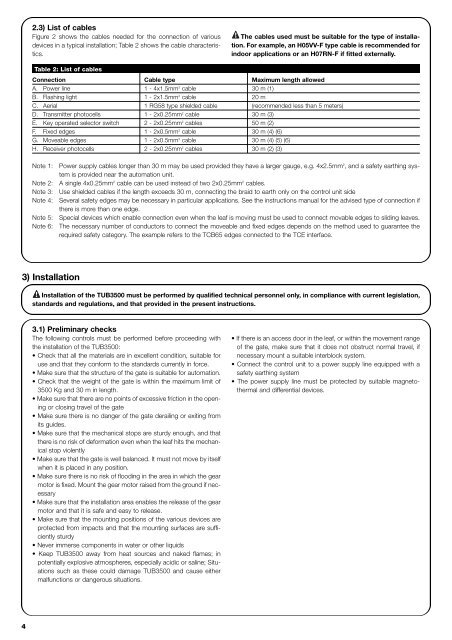
2.3) List of cables<br />
Figure 2 shows the cables needed for the connection of various<br />
devices in a typical installation; Table 2 shows the cable characteristics.<br />
! The cables used must be suitable for the type of installation.<br />
For example, an H05VV-F type cable is re<strong>com</strong>mended for<br />
indoor applications or an H07RN-F if fitted externally.<br />
Table 2: List of cables<br />
Connection Cable type Maximum length allowed<br />
A. Power line 1 - 4x1.5mm 2 cable 30 m (1)<br />
B. Flashing light 1 - 2x1.5mm 2 cable 20 m<br />
C. Aerial 1 RG58 type shielded cable (re<strong>com</strong>mended less than 5 meters)<br />
D. Transmitter photocells 1 - 2x0.25mm 2 cable 30 m (3)<br />
E. Key operated selector switch 2 - 2x0.25mm 2 cables 50 m (2)<br />
F. Fixed edges 1 - 2x0.5mm 2 cable 30 m (4) (6)<br />
G. Moveable edges 1 - 2x0.5mm 2 cable 30 m (4) (5) (6)<br />
H. Receiver photocells 2 - 2x0.25mm 2 cables 30 m (2) (3)<br />
Note 1:<br />
Note 2:<br />
Note 3:<br />
Note 4:<br />
Note 5:<br />
Note 6:<br />
Power supply cables longer than 30 m may be used provided they have a larger gauge, e.g. 4x2.5mm 2 , and a safety earthing system<br />
is provided near the automation unit.<br />
A single 4x0.25mm 2 cable can be used instead of two 2x0.25mm 2 cables.<br />
Use shielded cables if the length exceeds 30 m, connecting the braid to earth only on the control unit side<br />
Several safety edges may be necessary in particular applications. See the instructions manual for the advised type of connection if<br />
there is more than one edge.<br />
Special devices which enable connection even when the leaf is moving must be used to connect movable edges to sliding leaves.<br />
The necessary number of conductors to connect the moveable and fixed edges depends on the method used to guarantee the<br />
required safety category. The example refers to the TCB65 edges connected to the TCE interface.<br />
3) Installation<br />
! Installation of the TUB3500 must be performed by qualified technical personnel only, in <strong>com</strong>pliance with current legislation,<br />
standards and regulations, and that provided in the present instructions.<br />
3.1) Preliminary checks<br />
The following controls must be performed before proceeding with<br />
the installation of the TUB3500:<br />
• Check that all the materials are in excellent condition, suitable for<br />
use and that they conform to the standards currently in force.<br />
• Make sure that the structure of the gate is suitable for automation.<br />
• Check that the weight of the gate is within the maximum limit of<br />
3500 Kg and 30 m in length.<br />
• Make sure that there are no points of excessive friction in the opening<br />
or closing travel of the gate<br />
• Make sure there is no danger of the gate derailing or exiting from<br />
its guides.<br />
• Make sure that the mechanical stops are sturdy enough, and that<br />
there is no risk of deformation even when the leaf hits the mechanical<br />
stop violently<br />
• Make sure that the gate is well balanced. It must not move by itself<br />
when it is placed in any position.<br />
• Make sure there is no risk of flooding in the area in which the gear<br />
motor is fixed. Mount the gear motor raised from the ground if necessary<br />
• Make sure that the installation area enables the release of the gear<br />
motor and that it is safe and easy to release.<br />
• Make sure that the mounting positions of the various devices are<br />
protected from impacts and that the mounting surfaces are sufficiently<br />
sturdy<br />
• Never immerse <strong>com</strong>ponents in water or other liquids<br />
• Keep TUB3500 away from heat sources and naked flames; in<br />
potentially explosive atmospheres, especially acidic or saline; Situations<br />
such as these could damage TUB3500 and cause either<br />
malfunctions or dangerous situations.<br />
• If there is an access door in the leaf, or within the movement range<br />
of the gate, make sure that it does not obstruct normal travel, if<br />
necessary mount a suitable interblock system.<br />
• Connect the control unit to a power supply line equipped with a<br />
safety earthing system<br />
• The power supply line must be protected by suitable magnetothermal<br />
and differential devices.<br />
4


