GB - Nice-service.com
GB - Nice-service.com
GB - Nice-service.com

Create successful ePaper yourself
Turn your PDF publications into a flip-book with our unique Google optimized e-Paper software.
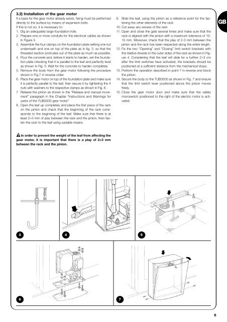
3.2) Installation of the gear motor<br />
If a base for the gear motor already exists, fixing must be performed<br />
directly to the surface by means of expansion bolts.<br />
If this is not so, it is necessary to:<br />
1. Dig an adequately large foundation hole.<br />
2. Prepare one or more conduits for the electrical cables as shown<br />
in Figure 5<br />
3. Assemble the four clamps on the foundation plate setting one nut<br />
underneath and one on top of the plate as in fig. 3. so that the<br />
threaded section protrudes out of the plate as much as possible.<br />
4. Pour the concrete and, before it starts to harden, set the foundation<br />
plate checking that it is parallel to the leaf and perfectly level<br />
as shown in Fig. 5. Wait for the concrete to harden <strong>com</strong>pletely<br />
5. Remove the body from the gear motor following the procedure<br />
shown in Fig.7 in reverse order.<br />
6. Place the gear motor on top of the foundation plate and make sure<br />
it is perfectly parallel to the leaf, then secure it by tightening the 4<br />
nuts with washers to the respective clamps as shown in Fig. 6.<br />
7. Release the pinion as shown in the “Release and manual movement”<br />
paragraph in the Chapter “Instructions and Warnings for<br />
users of the TUB3500 gear motor”<br />
8. Open the leaf up <strong>com</strong>pletely and place the first piece of the rack<br />
on the pinion and check that the beginning of the rack corresponds<br />
to the beginning of the leaf. Make sure that there is at<br />
least 2÷3 mm of play between the rack and the pinion, then fasten<br />
the rack to the leaf using suitable means.<br />
9. Slide the leaf, using the pinion as a reference point for the fastening<br />
the other elements of the rack<br />
10. Cut away any excess of the rack<br />
11. Open and close the gate several times and make sure that the<br />
rack is aligned with the pinion with a maximum tolerance of 10-<br />
15 mm. Moreover, check that the play of 2-3 mm between the<br />
pinion and the rack has been respected along the entire length.<br />
12. Fix the two “Opening” and “Closing” limit switch brackets with<br />
the relative dowels to the outer sides of the rack as shown in Figure<br />
4. Considering that the leaf will slide for a further 2÷3 cm<br />
after the limit switches have activated, the brackets should be<br />
positioned at a sufficient distance from the mechanical stops.<br />
13. Perform the operation described in point 7 in reverse and block<br />
the pinion.<br />
14. Secure the body to the TUB3500 as shown in Fig. 7 and ensure<br />
that the limit switch lever positioned above the pinion moves<br />
freely.<br />
15. Close the gear motor door and make sure that the safety<br />
microswitch positioned to the right of the electric motor is activated.<br />
<strong>GB</strong><br />
! In order to prevent the weight of the leaf from affecting the<br />
gear motor, it is important that there is a play of 2÷3 mm<br />
between the rack and the pinion.<br />
3<br />
4 5<br />
6 7<br />
5