RVM Betriebsanleitung
RVM Betriebsanleitung
RVM Betriebsanleitung

Create successful ePaper yourself
Turn your PDF publications into a flip-book with our unique Google optimized e-Paper software.
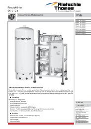
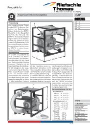
1.2 Description<br />
The <strong>RVM</strong> vacuum stations comprise two vacuum pumps (VCE<br />
or VCEH type), a horizontal tank and a programmable control<br />
panel. They can also include a bacteriological filter with bypass.<br />
Each pump is equipped with a non-return valve so that<br />
once the pump is stopped air cannot enter the evacuated system<br />
or oil accumulate in the pressure chamber that would give<br />
rise to jerky starting. A manual valve is mounted on every device<br />
in order to isolate the pump for maintenance. The inlet of<br />
each pump can also be fitted with a control valve for constant<br />
vacuum regulation.<br />
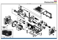
1.2.1 Vacuum pumps<br />
The vacuum pumps are of the oil lubricated rotary vane type<br />
and have built-in oil mist separator. Each pump is equipped<br />
with an inlet screen filter of stainless steel material.<br />
1.2.2 Tank<br />
Capacity: Horizontal, 500, 1000 or 1500 litres with external<br />
paint finish. Material steel ST37-2 a galvanised version or<br />
vertical tanks can be manufactured upon request.<br />
Every tank is equipped with a valve of purge and must<br />
be used only for vacuum.<br />
1.2.3 Control Panel<br />
It controls the whole vacuum station through a programmable<br />
controller. Every panel features a display keyboard with<br />
a switch case comprising the electromechanical operating<br />
material.<br />
The control panel corresponds to the latest European standards<br />
(see operating manual control panel)<br />
1.2.4 Bacteriological filtration (optional accessories)<br />
Every station can be delivered with single or double bacteriological<br />
filter with by-pass to prevent bacteria passing<br />
through the equipment. It is fitted with a drain valve and a<br />
filter with bacteriological cartridge (for double filtration, a<br />
second filter is put in the by-pass).<br />
1.3 Application<br />
Vacuum stations are suction systems intended for<br />
medical use.<br />
They are designed to work in a pressure range of 150 mbar<br />
(abs.) to 350 mbar (abs.). Limitations of the operating pressure<br />
range are specified in the vacuum pump manual.<br />
The air must be free of water and other liquids. Aggressive<br />
or flammable gases and vapours cannot be<br />
drawn.<br />
The ambient and inlet temperatures must range from 5 to<br />
40°C. For other temperatures please contact us.<br />
The vacuum and function alarms must always be connected<br />
and all the safety standards met in order to<br />
prevent exposing the persons to danger.<br />
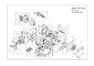
1.4 Handling and setting up<br />
A normally operated station can present pump surface<br />
temperatures for the elements (Q) above 70°C.<br />
Any contact with these parts must be avoided.<br />
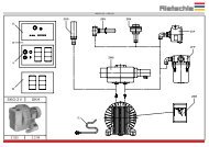
The following parts must be easily accessible; filter casing (D),<br />
oil filler opening (H), oil sight glass (I), oil drain (K), gas ballast<br />
(U) and oil separator housing (T). The cooling air inlets (E) and<br />
outlets (F) must be separated from the surrounding walls by<br />
min. 20 cm. For easier maintenance a space of 0,4 m is recommended<br />
in front of the filter casing and the oil separator housing.<br />
RMV stations can only be correctly used in a horizontal<br />
position.<br />
The control panel must only be opened and checked<br />
when switched off and by a skilled worker, in accordance<br />
with the EN 60204 standard.<br />
The panel and electromechanical sub-system must remain free<br />
for display, programming and repairing.<br />
The bacteriological filtration and the collection pot<br />
must remain accessible for maintenance purposes.<br />
Should the station be installed higher than 1000 m over<br />
the sea level, a decrease in performance will take place. In<br />
this case, please contact us.<br />
The vacuum station must be installed in a ventilated plant<br />
room where the temperature should not exceed 40°C.<br />
Appropriate ventilation has to be provided. The room must<br />
be easily accessible.<br />
Compliance with the Directive concerning protection<br />
of labour must be observed as far as station installation<br />
and operating are concerned.<br />
1. Vacuum connection is found at the left end of the tank.<br />
The station performance will be affected if the inlet<br />
pipework is undersized and/or too lang. Discharge<br />
has to be directed outside in accordance with the current<br />
standards. It must not be closed or occluded. A<br />
discharge pot must be installed.<br />
2. You have to check whether oil condensate is present in<br />
the vacuum pumps (upper warning light (I) and add if necessary).<br />
3. Connect the control panel to the main supply via a circuit<br />
breaker. Check that the supply is compatible (current, voltage,<br />
frequency).<br />
The electrical connections and installation can only<br />
be performed by a skilled worker according to the<br />
EN 60204 standard. The main switch (circuit breaker) of<br />
the room has to be provided by the user.<br />
1.5 Setting<br />
The starting should be realized by Rietschle or a partner<br />
of Rietschle.<br />
The panel screws must be checked and screwed up if necessary<br />
before setting.<br />
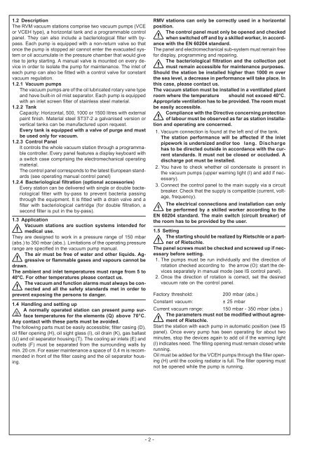
1. The pumps must be run individually and the direction of<br />
rotation checked according to the arrow (O): start the devices<br />
separately in manual mode (see IS control panel).<br />
2. Once the direction of rotation is correct, set the desired<br />
vacuum rate on the control panel.<br />
Factory threshold:<br />
200 mbar (abs.)<br />
Constant vacuum:<br />
± 25 mbar<br />
Current vacuum range: 150 mbar - 350 mbar (abs.)<br />
The parameters must not be modified without agreement<br />
of Rietschle.<br />
Start the station with each pump in automatic position (see IS<br />
panel). Once every pump has been operating for about two<br />
minutes, stop the devices again to add oil if the warning light<br />
(I) indicates need. The filling opening must remain closed while<br />
running.<br />
Oil must be added for the VCEH pumps through the filler opening<br />
(H) until the cooling radiator is full. The filler opening must<br />
not be opened while the pump is running.<br />
- 2 -