RVM Betriebsanleitung
RVM Betriebsanleitung
RVM Betriebsanleitung

You also want an ePaper? Increase the reach of your titles
YUMPU automatically turns print PDFs into web optimized ePapers that Google loves.
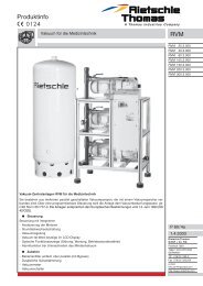
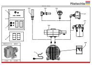
2.4 Handling and Setting up<br />
Filter housing (D), oil filler ports (H, H 1 ), oil sight glass (I), oil drain<br />
plugs (K, K 1 ), gas ballast (U) and oil separator housing (T) must<br />
all be easily accessible. The cooling air entries (E) and the<br />
cooling air exits (F) must have a minimum distance of 20 cm from<br />
any obstruction. The discharged cooling air must not be recirculated.<br />
For maintenance purposes we recommend a space<br />
of 0.5 m in front of the filter housing and oil separator.<br />
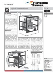
The VCE and VCEH pumps can only be operated<br />
reliably if they are installed horizontally.<br />
When installed on a solid base, the pumps may be installed<br />
without fixing down. If the pumps are installed on a base plate<br />
we would recommend fitting anti vibration mounts. This range<br />
of vacuum pumps are almost vibration free in operation.<br />
2.5 Potential risks for operating personnel<br />
1.Noise Emission: The worst noise levels considering direction<br />
and intensity measured according to DIN 45635 part 3 (as per<br />
3. GSGV) are shown in the table at the back. When working<br />
permanently in the vicinity of an operating pump we recommend<br />
wearing ear protection to avoid any damage to hearing.<br />
2.Oil mist in the Exhaust Stream: Even with the high efficiency<br />
oil mist eliminator the exhausted air could still contain extremely<br />
low amounts of oil mist which can occasionally be<br />
detected by smell. Permanent inhalation of these mists may<br />
result in health problems, therefore it is extremely important to<br />
make sure that the installation area is well ventilated.<br />
VCE<br />
D<br />
VCEH<br />
f 1<br />
Q<br />
s 1<br />
T<br />
Q<br />
M<br />
K<br />
H<br />
I<br />
Q<br />
2.6 Maintenance and Servicing<br />
When maintaining these units and having such situations<br />
where personnel could be hurt by moving parts D<br />
or by live electrical parts the pump must be isolated by<br />
totally disconnecting the electrical supply. It is imperative<br />
that the unit cannot be re-started during the maintenance<br />
operation.<br />
Do not work on a pump that is at its normal operating<br />
temperature as there is a danger from hot parts or hot<br />
lubricant.<br />
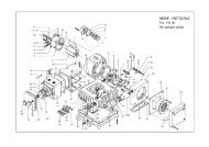
2.6.1 Air filtration<br />
<br />
The capacity of the pump can become reduced if the<br />
air inlet filters are not maintained correctly.<br />
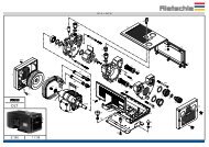
Filters on the suction side: Mesh filter (f 1 ) must be cleaned regularly depending upon the<br />
amount of contamination. Cleaning can be carried out by washing out or by blowing out with<br />
compressed air. Replace filters if contaminated completely.<br />
The mesh filter (f 1 ) can be dismantled by removing screws (s 1 ) on the filter housing (D)<br />
(picture ).<br />
Filter for Gas ballast: All pumps are equipped with a gas ballast valve (U).<br />
VCE 15-100 / VCEH 100: The built in disc (f 3 ) and mesh discs (f 4 ) must be cleaned regularly<br />
depending upon the amount of contamination by blowing out with compressed air. By<br />
removing the screw (g 1 ) and plastic cap (h 1 ) the filter elements can be removed for cleaning.<br />
Re-assemble in reverse order (picture ).<br />
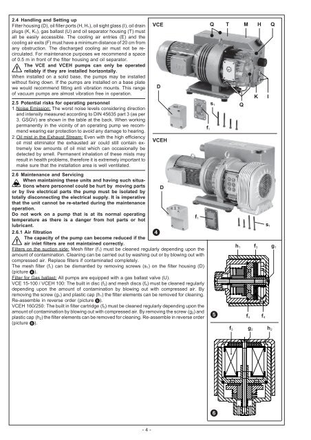
VCEH 160/250: The built in filter cartridge (f 5 ) must be cleaned regularly depending upon the<br />
amount of contamination by blowing out with compressed air. By removing the screw (g 2 ) and<br />
plastic cap (h 2 ) the filter elements can be removed for cleaning. Re-assemble in reverse order<br />
(picture ).<br />
<br />
h 1<br />
f 4 f 4<br />
s 1<br />
f 3 g 1<br />
f 1<br />
f 5 g 2 h 2<br />
<br />
- 4 -