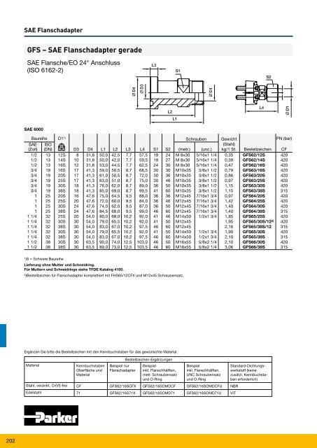
202 SAE Flanschadapter GFS – SAE Flanschadapter gerade SAE Flansche/EO 24° Anschluss (ISO 6162-2) SAE 6000 Baureihe D11) Schrauben Gewicht PN (bar) SAE ISO (Stahl) (Zoll) (DN) D3 D4 L1 L2 L3 L4 S1 S2 (metr.) (unc.) kg/1 St. Bestellzeichen CF 1/2 13 12S 8 31,8 50,0 42,5 7,7 57,5 19 24 M 8x30 5/16x1 1/4 0,35 GFS62/12S 420 1/2 13 14S 10 31,8 50,0 42,0 7,7 59,5 19 27 M 8x30 5/16x1 1/4 0,39 GFS62/14S 420 1/2 13 16S 12 31,8 53,0 44,5 7,7 62,5 24 30 M 8x30 5/16x1 1/4 0,47 GFS62/16S 420 3/4 19 16S 17 41,3 59,0 50,5 8,7 68,5 30 30 M10x35 3/8x1 1/2 0,79 GFS63/16S 420 3/4 19 20S 17 41,3 61,0 50,5 8,7 72,0 30 36 M10x35 3/8x1 1/2 0,86 GFS63/20S 420 3/4 19 25S 17 41,3 63,0 51,0 8,7 75,0 30 46 M10x35 3/8x1 1/2 0,97 GFS63/25S 420 3/4 19 30S 18 41,3 76,0 62,0 8,7 89,0 36 50 M10x35 3/8x1 1/2 1,15 GFS63/30S 420 3/4 19 38S 18 41,3 85,0 69,0 8,7 99,5 41 60 M10x35 3/8x1 1/2 1,15 GFS63/38S 315 1 25 20S 16 47,6 75,0 64,5 9,5 88,0 36 36 M12x45 7/16x1 3/4 0,97 GFS64/20S 420 1 25 25S 20 47,6 72,0 60,0 9,5 84,0 36 46 M12x45 7/16x1 3/4 1,42 GFS64/25S 420 1 25 30S 24 47,6 74,0 62,0 9,5 87,0 36 50 M12x45 7/16x1 3/4 1,40 GFS64/30S 420 1 25 38S 24 47,6 84,5 68,0 9,5 99,0 46 60 M12x45 7/16x1 3/4 1,40 GFS64/38S 315 1 1/4 32 25S 20 54,0 80,0 68,0 10,2 92,0 41 46 M14x50 1/2x1 3/4 1,85 GFS65/25S 420 1 1/4 32 30S 30 54,0 79,0 65,5 10,2 92,0 41 50 M12x45 1,95 GFS65/30S/122) 420 1 1/4 32 38S 30 54,0 83,0 67,0 10,2 97,5 46 60 M12x45 2,16 GFS65/38S/12 315 1 1/4 32 30S 30 54,0 79,0 65,5 10,2 92,0 41 50 M14x50 1/2x1 3/4 1,90 GFS65/30S 420 1 1/4 32 38S 30 54,0 83,0 67,0 10,2 97,5 46 60 M14x50 1/2x1 3/4 2,10 GFS65/38S 315 1 1/2 38 30S 30 63,5 90,0 74,0 12,5 103,0 46 50 M16x55 5/8x2 1/4 2,10 GFS66/30S 420 1 1/2 38 38S 30 63,5 89,0 73,0 12,5 103,5 46 60 M16x55 5/8x2 1/4 3,06 GFS66/38S 315 1 )S = Schwere Baureihe Lieferung ohne Mutter <strong>und</strong> Schneidring. Für Muttern <strong>und</strong> Schneidringe siehe TFDE Katalog 4100. 2 )Bestellzeichen für Flanschadapter komplettiert mit FHS65/12CFX <strong>und</strong> M12x45 Schraubensatz. Ergänzen Sie bitte die Bestellzeichen mit den Kennbuchstaben für das gewünschte Material. Material Kennbuchstaben Oberfläche <strong>und</strong> Material Beispiel nur Flanschadapter Bestellzeichen-Ergänzungen Beispiel inkl. Flanschhälften, metr. Schraubensatz <strong>und</strong> O-Ring Beispiel inkl. Flanschhälften, UNC Schraubensatz <strong>und</strong> O-Ring Stahl, verzinkt, Cr(VI)-frei CF GFS62/16SCFX GFS62/16SOMDCF GFS62/16SOMDCFU NBR Edelstahl 71 GFS62/16S71X GFS62/16SOMD71 GFS62/16SOMD71U VIT Standard-Dichtungswerkstoff (keine zusätzl. Kennbuchstaben erforderlich)
WFS – SAE 90° Winkel Flanschadapter SAE Flansche/EO 24° Anschluss (ISO 6162-1) SAE Flanschadapter SAE 3000 Baureihe D11 ) Schrauben Gewicht SAE ISO (Stahl) (Zoll) (DN) D3 D4 L1 L2 L3 L4 L5 S1 S2 (metr.) (unc.) kg/1 St. Bestellzeichen PN (bar) 1/2 13 12S 12 30,2 50 42,5 6,7 44 58,5 22 24 M 8×25 5/16×1 1/4 0,38 WFS32/12S 210 1/2 13 15L 12 30,2 36 29,0 6,7 36 44,0 24 27 M 8×25 5/16×1 1/4 0,40 WFS32/15L 315 1/2 13 16S 12 30,2 38 29,5 6,7 36 48,0 24 30 M 8×25 5/16×1 1/4 0,43 WFS32/16S 350 1/2 13 18L 12 30,2 50 42,5 6,7 44 59,0 22 32 M 8×25 5/16×1 1/4 0,44 WFS32/18L 315 3/4 19 16S 19 38,1 64 55,5 6,7 53 73,5 27 30 M10×30 3/8×1 1/4 0,60 WFS33/16S 350 3/4 19 18L 19 38,1 39 31,5 6,7 42 48,0 30 32 M10×30 3/8×1 1/4 0,66 WFS33/18L 315 3/4 19 22L 19 38,1 41 33,5 6,7 42 50,0 30 36 M10×30 3/8×1 1/4 0,66 WFS33/22L 160 3/4 19 20S 17 38,1 43 32,5 6,7 42 54,0 30 36 M10×30 3/8×1 1/4 0,76 WFS33/20S 350 3/4 19 25S 17 38,1 45 33,0 6,7 42 57,0 30 46 M10×30 3/8×1 1/4 0,89 WFS33/25S 350 1 25 20S 20 44,5 65 54,5 8,0 60 77,0 34 36 M10×30 3/8×1 1/4 0,78 WFS34/20S 350 1 25 22L 18 44,5 65 57,5 8,0 60 74,0 34 36 M10×30 3/8×1 1/4 0,81 WFS34/22L 160 1 25 28L 25 44,5 44 36,5 8,0 45 53,0 36 41 M10×30 3/8×1 1/4 0,85 WFS34/28L 160 1 25 25S 20 44,5 48 36,5 8,0 45 57,0 36 46 M10×30 3/8×1 1/4 0,95 WFS34/25S 350 1 25 30S 24 44,5 50 36,5 8,0 45 63,0 36 50 M10×30 3/8×1 1/4 1,06 WFS34/30S 250 1 1/4 32 35L 32 50,8 57 46,5 8,0 50 68,0 41 50 M10×35 3/8×1 1/4 1,15 WFS35/35L/102 ) 160 1 1/4 32 25S 27 50,8 55 43,0 8,0 60 67,0 41 46 M10×35 3/8×1 1/4 1,35 WFS35/25S/10 200 1 1/4 32 30S 28 50,8 57 43,5 8,0 50 70,0 41 50 M10×35 3/8×1 1/4 1,40 WFS35/30S/10 200 1 1/4 32 38S 28 50,8 59 43,0 8,0 50 74,0 46 60 M10×35 3/8×1 1/4 1,53 WFS35/38S/10 200 1 1/4 32 35L 32 50,8 57 46,5 8,0 50 68,0 41 50 M12×40 7/16×1 1/2 1,15 WFS35/35L 160 1 1/4 32 25S 27 50,8 55 43,0 8,0 50 67,0 41 46 M12×40 7/16×1 1/2 1,35 WFS35/25S 200 1 1/4 32 30S 28 50,8 57 43,5 8,0 50 70,0 41 50 M12×40 7/16×1 1/2 1,40 WFS35/30S 200 1 1/4 32 38S 28 50,8 59 43,0 8,0 50 74,0 41 60 M12×40 7/16×1 1/2 1,53 WFS35/38S 200 1 1/2 38 35L 30 60,3 78 67,5 8,0 66 83,0 50 50 M12×35 1/2×1 1/2 1,55 WFS36/35L 160 1 1/2 38 42L 36 60,3 58 47,0 8,0 55 70,0 50 60 M12×35 1/2×1 1/2 1,60 WFS36/42L 160 1 1/2 38 38S 36 60,3 64 48,0 8,0 55 79,0 50 60 M12×35 1/2×1 1/2 1,95 WFS36/38S 200 1 )L = Leichte Baureihe; S = Schwere Baureihe Lieferung ohne Mutter <strong>und</strong> Schneidring. Für Muttern <strong>und</strong> Schneidringe siehe TFDE Katalog 4100. 2) Bestellzeichen für Winkelflanschadapter komplettiert mit FHS35/10CFX <strong>und</strong> M10x35 Schraubensatz. Ergänzen Sie bitte die Bestellzeichen mit den Kennbuchstaben für das gewünschte Material. Material Kennbuchstaben Oberfläche <strong>und</strong> Material Beispiel nur Flanschadapter Bestellzeichen-Ergänzungen Beispiel inkl. Flanschhälften, metr. Schraubensatz <strong>und</strong> O-Ring Beispiel inkl. Flanschhälften, UNC Schraubensatz <strong>und</strong> O-Ring Stahl, verzinkt, Cr(VI)-frei CF WFS32/16SCFX WFS32/16SOMDCF WFS32/16SOMDCFU NBR Edelstahl 71 WFS32/16S71X WFS32/16SOMD71 WFS32/16SOMD71U VIT Standard-Dichtungswerkstoff (keine zusätzl. Kennbuchstaben erforderlich) 203
- Seite 1 und 2:
Parker weltweit Europa, Naher Osten
- Seite 3 und 4:
Inhalt Parflange ® F37 für Rohr-u
- Seite 5 und 6:
Einleitung 5
- Seite 7 und 8:
Allgemeine Informationen 7
- Seite 9 und 10:
Parflange ® F37 Technologie Börde
- Seite 11 und 12:
Parflange ® F37 Technologie Grunds
- Seite 13 und 14:
Verbindungsverfahren F37 - gebörde
- Seite 15 und 16:
Notizen 15
- Seite 17 und 18:
Technische Daten 17
- Seite 19 und 20:
Toleranzen und Standards Gewinde Au
- Seite 21 und 22:
Installation F37 Flanschsystem Aktu
- Seite 23 und 24:
Maschinen, Werkzeuge und Zubehör 2
- Seite 25 und 26:
Eine.hervorragende.Dichtfläche.wir
- Seite 27 und 28:
Montagemaschinen EO-KARRYMAT EOMAT
- Seite 29 und 30:
Montagemaschinen EO2-FORM PRO22 Kar
- Seite 31 und 32:
Montagemaschinen Parflange ® 1025
- Seite 33 und 34:
Montagemaschinen LUBSS Handwerkzeug
- Seite 35 und 36:
Montagemaschinen Maschinen, Werkzeu
- Seite 37 und 38:
Montagemaschinen DB 650ST DB 642 CN
- Seite 39 und 40:
Montagemaschinen Rohrlagersystem Nu
- Seite 41 und 42:
TFV - Bördelflanschverbindung Rohr
- Seite 43 und 44:
Parflange ® Haltering Bestellschl
- Seite 45 und 46:
SAE 1000 System 50 - 70 bar 45
- Seite 47 und 48:
F37 - Bördelflansch | SAE 1000/ISO
- Seite 49 und 50:
TFV - Bördelflansch Verbindung Roh
- Seite 51 und 52:
TT - Bördelflansch Verbindung Rohr
- Seite 53 und 54:
MTF-R - Adapter mit Außengewinde,
- Seite 55 und 56:
WA - Schweißadapter Verbindung, we
- Seite 57 und 58:
BF - Schottflansch, weichdichtend S
- Seite 59 und 60:
RF - Reduzierflansch, weichdichtend
- Seite 61 und 62:
LF - Winkelflansch SAE 1000/ISO 616
- Seite 63 und 64:
TF/TF-R - T-Flansch, weichdichtend
- Seite 65 und 66:
BFV - Verschlussflansch F37 Dichtun
- Seite 67 und 68:
Schrauben und Muttern für Flansche
- Seite 69 und 70:
SAE 3000 System 210 - 350 bar 69
- Seite 71 und 72:
Programmübersicht SAE 3000/ISO 616
- Seite 73 und 74:
Teilekombination Bördel SAE 3000 F
- Seite 75 und 76:
PSC - Rohr Dichtringträger | SAE 3
- Seite 77 und 78:
TFV - Bördelflanschverbindung Rohr
- Seite 79 und 80:
TF - Bördelflanschverbindung Rohr
- Seite 81 und 82:
R - Haltering SAE 3000/ISO 6162-1 B
- Seite 83 und 84:
MTF-N - Adapter mit Außengewinde,
- Seite 85 und 86:
Haltering Schlauchadapter SAE 3000/
- Seite 87 und 88:
WA - Schweißadapter Verbindung For
- Seite 89 und 90:
VB - Vibrationsschottflansch SAE 30
- Seite 91 und 92:
FB90 - 90° Flanschbogen SAE 3000/I
- Seite 93 und 94:
LF - Winkelflansch SAE 3000/ISO 616
- Seite 95 und 96:
LB - Flansch L-Block SAE 3000/ISO 6
- Seite 97 und 98:
TB - Flansch T-Block SAE 3000/ISO 6
- Seite 99 und 100:
BFV - Verschlussflansch SAE 3000/IS
- Seite 101 und 102:
AO - Adapter Verbunddichtung zu F37
- Seite 103 und 104:
AP - SAE Flansch Abdichtplatte SAE
- Seite 105 und 106:
KH - Kugelhahn 400 bar Innengewinde
- Seite 107 und 108:
KH-R - Kugelhahn mit SAE 3000 Flans
- Seite 109 und 110:
SAE 6000 System 420 bar 109
- Seite 111 und 112:
Programmübersicht SAE 6000/ISO 616
- Seite 113 und 114:
Teilekombination Bördel SAE 6000 F
- Seite 115 und 116:
PSC - Rohr Dichtringträger | SAE 6
- Seite 117 und 118:
TFV - Bördelflanschverbindung Rohr
- Seite 119 und 120:
TF - Bördelflanschverbindung Rohr
- Seite 121 und 122:
R - Haltering SAE 6000/ISO 6162-2 B
- Seite 123 und 124:
MTF-N - Adapter mit Außengewinde,
- Seite 125 und 126:
Haltering Schlauchadapter SAE 6000/
- Seite 127 und 128:
WA - Schweißadapter Verbindung For
- Seite 129 und 130:
VB - Vibrationsschottflansch SAE 60
- Seite 131 und 132:
FB90 - 90° Flanschbogen SAE 6000/I
- Seite 133 und 134:
LF - Winkelflansch SAE 6000/ISO 616
- Seite 135 und 136:
LB - Flansch L-Block SAE 6000/ISO 6
- Seite 137 und 138:
TB - Flansch T-Block SAE 6000/ISO 6
- Seite 139 und 140:
BFV - Verschlussflansch SAE 6000/IS
- Seite 141 und 142:
AO - Adapter Verbunddichtung zu F37
- Seite 143 und 144:
AP - SAE Flansch Abdichtplatte SAE
- Seite 145 und 146:
KH - Kugelhahn 400 Außengewinde BS
- Seite 147 und 148:
KH-R - Kugelhahn mit SAE 6000 Flans
- Seite 149 und 150:
ISO 6164 System 250 - 400 bar 149
- Seite 151 und 152: Programmübersicht ISO 6164 Bohrbil
- Seite 153 und 154: Teilekombination Bördel ISO 6164 F
- Seite 155 und 156: PSC - Rohr Dichtringträger | ISO 6
- Seite 157 und 158: TFV - Bördelflanschverbindung Rohr
- Seite 159 und 160: TF - Bördelflanschverbindung Rohr
- Seite 161 und 162: R - Haltering ISO 6164 Baureihe Zol
- Seite 163 und 164: MTF-N - Adapter mit Außengewinde,
- Seite 165 und 166: Haltering Schlauchadapter ISO 6164
- Seite 167 und 168: BF - Schottflansch ISO 6164 Ergänz
- Seite 169 und 170: RF - Reduzierflansch ISO 6164 Ergä
- Seite 171 und 172: FB45 - 45° Flanschbogen ISO 6164 E
- Seite 173 und 174: TF - T-Flansch ISO 6164 Parflange
- Seite 175 und 176: TB - Flansch-T-Block ISO 6164 Parfl
- Seite 177 und 178: BFV - Verschlussflansch ISO 6164 Ge
- Seite 179 und 180: AO - Adapter Verbunddichtung zu F37
- Seite 181 und 182: Schrauben und Muttern für Flansche
- Seite 183 und 184: KH - Kugelhahn Bohrung und Gewinde
- Seite 185 und 186: RHD-R - Rückschlagventile ISO 6164
- Seite 187 und 188: Flanschventile 187
- Seite 189 und 190: Kenndaten Serie C5V Direktbetätigt
- Seite 191 und 192: Kenndaten Serie C5V C5V06 C5V08 C5V
- Seite 193 und 194: Notizen 193
- Seite 195 und 196: SAE Flanschadapter 195
- Seite 197 und 198: Bestellzeichen Schrauben und O-Ring
- Seite 199 und 200: FHS - SAE Flanschhälften SAE 3000/
- Seite 201: GFS - SAE Flanschadapter gerade SAE
- Seite 205 und 206: L(O)HQ - SAE Flanschadapter gerade
- Seite 207 und 208: XHQ - SAE Flanschadapter gerade SAE
- Seite 209 und 210: PFF-G - SAE Vollflansche mit BSPP G
- Seite 211 und 212: PEFF-G - SAE 90° Vollflansche mit
- Seite 213 und 214: AP - SAE Flansch-Abschlussplatte IS
- Seite 215 und 216: Rohrschellen 215
- Seite 217 und 218: Rohrschellen DIN 3015 Programm: Roh
- Seite 219 und 220: Rohrschellen Montagehinweise DIN 30
- Seite 221 und 222: Rohrschellen Serie A (Leichtbaureih
- Seite 223 und 224: Rohrschellen Serie A (Leichtbaureih
- Seite 225 und 226: Rohrschellen Serie A (Leichtbaureih
- Seite 227 und 228: Rohrschellen Serie A (Leichtbaureih
- Seite 229 und 230: Rohrschellen Serie A - Komplett-Pro
- Seite 231 und 232: Rohrschellen Serie B (Zweirohrschel
- Seite 233 und 234: Rohrschellen Serie B - Komplett-Pro
- Seite 235 und 236: Rohrschellen Serie C (Schwere Baure
- Seite 237 und 238: Rohrschellen Serie C (Schwere Baure
- Seite 239 und 240: Rohrschellen Serie C (Schwere Baure
- Seite 241 und 242: Rohrschellen Serie C - Komplett-Pro
- Seite 243 und 244: Rohrschellen Serie C - Komplett-Pro
- Seite 245 und 246: Rohrschellen Serie C - Komplett-Pro
- Seite 247 und 248: Rohrschellen Serie C mit geräuschd
- Seite 249 und 250: Rohre und Leitungen 249
- Seite 251 und 252: Strömungsdurchmesser von Rohrleitu
- Seite 253 und 254:
Ölfluss und Druckverlust Alle Kalk
- Seite 255 und 256:
Rohrkalkulation für Landbasierte-
- Seite 257 und 258:
Rohre - Landbasierte- und Industrie
- Seite 259 und 260:
Rohre - Landbasierte- und Industrie
- Seite 261 und 262:
Rohre - Landbasierte- und Industrie