USER'S MANUAL Ampere hour meter BETRIEBSANLEITUNG ...
USER'S MANUAL Ampere hour meter BETRIEBSANLEITUNG ...
USER'S MANUAL Ampere hour meter BETRIEBSANLEITUNG ...

Erfolgreiche ePaper selbst erstellen
Machen Sie aus Ihren PDF Publikationen ein blätterbares Flipbook mit unserer einzigartigen Google optimierten e-Paper Software.
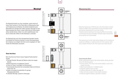
Der Messkopf besteht aus einer Leiterplatte, welche direkt auf<br />
einem Shunt montiert ist. Der Shunt dient zur Messung des Lade-<br />
und Entladestromes der Batterie. Die direkte Kontaktierung der<br />
Messelektronik verhindert den Einfluss äusserer Störungen auf das<br />
Spannungssignal des Shunts, sodass selbst kleinste Ströme genau<br />
erfasst werden können. Daher ist es nicht empfehlenswert, den<br />
Shunt indirekt über Drähte mit dem Messkopf zu verbinden.<br />
Der Messkopf kann auch ohne Anzeigeeinheit betrieben werden.<br />
Zum Beispiel als Präzisions-Interface zu einem Fahrzeugcomputer.<br />
Der Computer muss lediglich die Pulse an den Ausgängen am 10pol<br />
Stecker des Messkopfes auswerden.<br />
Shunt-Anschluss<br />
Beim Anschluss des Shunts müssen folgende Punkte beachtet<br />
werden:<br />
• Richtige Polarität: Minuspol der Batterie neben der orangen<br />
Klemme<br />
• Berührungsschutz im eingebauten Zustand<br />
• Schutz vor Staub, Feuchtigkeit und Spritzwasser<br />
• Ausreichender Querschnitt der verwendeten Kabel und Schienen<br />
(Siehe Seite 18)<br />
• blanke und saubere Kontaktstellen für geringe<br />
Übergangswiderstände<br />
• rüttelfeste Montage, speziell im Fahrzeugen<br />
17<br />
Messkopf Measuring Unit<br />
RJ45 Verbindung zur Anzeigeeinheit<br />
RJ45 Interconnection to display<br />
10-pol Verbindung zur Anzeigeeinheit<br />
10 pin interconnection to display unit<br />
U1<br />
U2<br />
T2<br />
T1<br />
10 9<br />
8 7<br />
6 5<br />
4 3<br />
2 1<br />
2 Lastkreis -<br />
Load<br />
1 Batterie -<br />
Battery<br />
2<br />
1<br />
Mounting measuring unit PCB directly on the shunt allows to avoid<br />
influence of EMI on the measurement accuracy and allows to perform<br />
precise measurements of very low currents.<br />
Therefore remote mounting of the measuring PCB and connecting<br />
it to the shunt with wires inevitably introduces large measurement<br />
errors and thus not recommended.<br />
The measuring unit can be used without display unit. For instance as<br />
a precision interface to a vehicle control unit. The computer needs<br />
only an digital interface to the 10 pin plug on the measuring unit.<br />
Connecting the Shunt<br />
While connecting the shunt to the traction battery, please pay attention<br />
to the following points:<br />
• Correct polarity: The minus of the traction battery is next to the<br />
orange 4 pin plug.<br />
• Shock hazard protection in installed system.<br />
• Protection against water and dust.<br />
• Sufficient dia<strong>meter</strong>s for cables (see page 18).<br />
• Clean and shiny contacts for low contact resistance.<br />
• Protection against vibration, especially in vehicles.<br />
Service<br />
Service