Einbauanleitung SCHRICK Schaltsaugrohr für VR6 Motoren Der ...
Einbauanleitung SCHRICK Schaltsaugrohr für VR6 Motoren Der ...
Einbauanleitung SCHRICK Schaltsaugrohr für VR6 Motoren Der ...
Erfolgreiche ePaper selbst erstellen
Machen Sie aus Ihren PDF Publikationen ein blätterbares Flipbook mit unserer einzigartigen Google optimierten e-Paper Software.
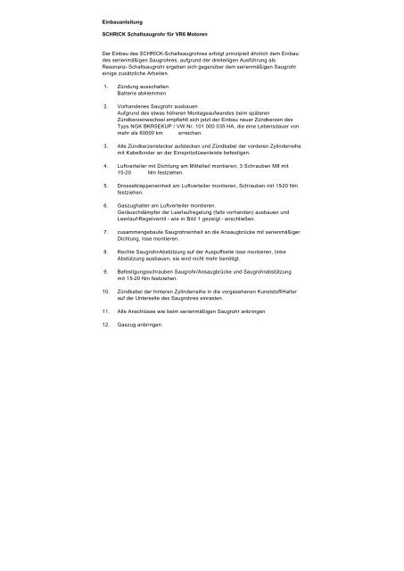
<strong>Einbauanleitung</strong><br />
<strong>SCHRICK</strong> <strong>Schaltsaugrohr</strong> <strong>für</strong> <strong>VR6</strong> <strong>Motoren</strong><br />
<strong>Der</strong> Einbau des <strong>SCHRICK</strong>-<strong>Schaltsaugrohr</strong>es erfolgt prinzipiell ähnlich dem Einbau<br />
des serienmäßigen Saugrohres, aufgrund der dreiteiligen Ausführung als<br />
Resonanz- <strong>Schaltsaugrohr</strong> ergeben sich gegenüber dem serienmäßigen Saugrohr<br />
einige zusätzliche Arbeiten.<br />
1. Zündung ausschalten<br />
Batterie abklemmen<br />
2. Vorhandenes Saugrohr ausbauen<br />
Aufgrund des etwas höheren Montageaufwandes beim späteren<br />
Zündkerzenwechsel empfiehlt sich jetzt der Einbau neuer Zündkerzen des<br />
Typs NGK BKR5EKUP / VW Nr. 101 000 035 HA, die eine Lebensdauer von<br />
mehr als 60000 km erreichen.<br />
3. Alle Zündkerzenstecker aufstecken und Zündkabel der vorderen Zylinderreihe<br />
mit Kabelbinder an der Einspritzdüsenleiste befestigen.<br />
4. Luftverteiler mit Dichtung am Mittelteil montieren, 3 Schrauben M8 mit<br />
15-20 Nm festziehen.<br />
5. Drosselklappeneinheit am Luftverteiler montieren, Schrauben mit 15-20 Nm<br />
festziehen.<br />
6. Gaszughalter am Luftverteiler montieren.<br />
Geräuschdämpfer der Leerlaufregelung (falls vorhanden) ausbauen und<br />
Leerlauf-Regelventil - wie in Bild 1 gezeigt - anschließen.<br />
7. zusammengebaute Saugrohreinheit an die Ansaugbrücke mit serienmäßiger<br />
Dichtung, lose montieren.<br />
8. Rechte Saugrohr-Abstützung auf der Auspuffseite lose montieren, linke<br />
Abstützung ausbauen, sie wird nicht mehr benötigt.<br />
9. Befestigungsschrauben Saugrohr/Ansaugbrücke und Saugrohrabstützung<br />
mit 15-20 Nm festziehen.<br />
10. Zündkabel der hinteren Zylinderreihe in die vorgesehenen Kunststoff-Halter<br />
auf der Unterseite des Saugrohres einrasten.<br />
11. Alle Anschlüsse wie beim serienmäßigen Saugrohr anbringen<br />
12. Gaszug anbringen
G:\268\EINBA<strong>VR6</strong>.DOC<br />
13. Unterdruckbehälter, Magnetventil und Saugrohr-Steuergerät an geeigneter<br />
Stelle befestigen. Aufgrund der Ausführung der o.g. Teile in Kunststoff sind<br />
diese an wärmegeschützten Orten anzubringen.<br />
14. Die Unterdruckschläuche - wie in Bild 2 gezeigt - anschließen und in<br />
geeigneter Weise verlegen. Das mit einem T-Stück versehene Schlauchende<br />
an der zum Bremskraftverstärker führenden Unterdruckleitung anschließen.<br />
15. Saugrohr-Steuergerät wie folgt anschließen:<br />
a) Stecker an Magnetventil<br />
b) rote Leitung an geschaltetes + (Klemme 15)<br />
c) schwarze Leitung an Masse<br />
d) blaue Leitung an Drehzahlmesser-Eingangssignal<br />
Das Drehzahlmesser-Signal kann an verschiedenen Fahrzeugtypen<br />
unterschiedliche Pole/Leitungen belegen, so daß Sie <strong>für</strong> jeden Fahrzeugtyp<br />
den richtigen Anschluß selbst ermitteln müssen.<br />
16. <strong>Der</strong> Schaltpunkt des Steuergerätes ist auf die Drehzahl 4.000 U/min.<br />
programmiert, d.h. bei steigender Drehzahl öffnet die Resonanzklappe bei<br />
4000 U/min.<br />
Die Hysterese ist auf 50 U/min. eingestellt, d.h. daß bei sinkender Drehzahl<br />
die Resonanzklappe bei 3950 U/min schließt. Zur Einstellung einer anderen<br />
Schaltdrehzahl muß das Saugrohr-Steuergerät geöffnet werden und die<br />
unter einer abgedichteten Klebefolie befindlichen Schalter, nach der<br />
beiliegenden Tabelle, auf die gewünschte Drehzahl eingestellt werden.<br />
Zum Schutz vor Feuchtigkeit müssen die Schalter anschließend wieder<br />
sorgfältig abgedichtet werden.<br />
17. Die Batterie sollte erst angeklemmt werden, wenn alle elektrischen Bauteile<br />
wieder angeschlossen sind, da sonst Fehlermeldungen in der Motorelektronik<br />
gespeichert werden, die anschließend von einer Fachwerkstatt gelöscht<br />
werden müssen.<br />
18. Bitte beachten Sie, daß durch den Einbau des <strong>Schaltsaugrohr</strong>es die<br />
Leistungscharakteristik des Motors verändert wird, wodurch die allgemeine<br />
Betriebserlaubnis erlischt. Zur Wiedererlangung der Betriebserlaubnis ist<br />
eine technische Untersuchung durch zuständige Stellen und die Eintragung<br />
der vorgenommenen Änderungen in die Fahrzeugpapiere notwendig.
G:\268\EINBA<strong>VR6</strong>.DOC
Einstellungen der Schaltdrehzahl<br />
Klappe öffnet bei:<br />
n<br />
Drehzahlhysterese,<br />
klappe schließt bei:<br />
n - Hyst.<br />
Schalter: 1 2 3 4 5 6 Schalter: 7 8<br />
n [1/min] Hyst. [1/min]<br />
Test off off off off off off 0 off off<br />
2000 off off on off on off 50 on off<br />
2100 on off on off on off 100 off on<br />
2200 off on on off on off 200 on on<br />
2300 on on on off on off<br />
2400 off off off on on off<br />
2500 on off off on on off<br />
2600 off on off on on off<br />
2700 on on off on on off<br />
2800 off off on on on off<br />
2900 on off on on on off<br />
3000 off on on on on off<br />
3100 on on on on on off<br />
3200 off off off off off on<br />
3300 on off off off off on<br />
3400 off on off off off on<br />
3500 on on off off off on<br />
3600 off off on off off on<br />
3700 on off on off off on<br />
3800 off on on off off on<br />
3900 on on on off off on<br />
4000 off off off on off on<br />
4100 on off off on off on<br />
4200 off on off on off on<br />
4300 on on off on off on<br />
4400 off off on on off on<br />
4500 on off on on off on<br />
4600 off on on on off on<br />
4700 on on on on off on<br />
4800 off off off off on on<br />
4900 on off off off on on<br />
5000 off on off off on on<br />
5100 on on off off on on<br />
5200 off off on off on on<br />
5300 on off on off on on<br />
5400 off on on off on on<br />
5500 on on on off on on<br />
5600 off off off on on on<br />
5700 on off off on on on<br />
5800 off on off on on on<br />
5900 on on off on on on<br />
6000 off off on on on on<br />
6100 on off on on on on<br />
6200 off on on on on on<br />
6300 on on on on on on<br />
G:\268\EINBA<strong>VR6</strong>.DOC
G:\268\EINBA<strong>VR6</strong>.DOC<br />
Bild 1<br />
Bild 2
Installation Instructions<br />
<strong>SCHRICK</strong> variable geometry intake manifold for <strong>VR6</strong> engines<br />
The installation of the <strong>SCHRICK</strong> variable intake manifold is principly similar to that<br />
of the standard manifold. Some additional work need to be done, compared to the<br />
standard intake manifold, due to the 3-part-design of the variable resonance<br />
system.<br />
1. Switch off ignition<br />
Disconnect battery<br />
2. Remove existing intake manifold.<br />
At this point it is recommended to install new spark plugs NGK BKR5EKUP<br />
VW No. 101 000 035 HA, which will last more than 60000 km.<br />
3. Fit all spark plug connectors and tie the high tension ignition leads of the<br />
front cylinder bank with cable ties to the injector rail.<br />
4. Assemble the air distributor with gasket to the manifold. Torque the 3 M8<br />
bolts<br />
to 15-20 Nm<br />
5. Assemble the throttle body to the air distributor. Torque the bolts<br />
to 15-20 Nm.<br />
6. Mount the accelerator cable bracket to the air distributor.<br />
Detach the noise damper of the idle control valve (wher present) and<br />
connect the idle control valve directly to the air distributor (see illus. 1)<br />
7. Loosely mount the assembled intake manifold unit with standard gasket to<br />
the engine.<br />
8. Loosely mount the right hand manifold support on the exhaust side. Detach<br />
the left hand manifold support, it is no longer required.<br />
9. Torque the fastening bolts of the manifold and manifold-support to 15-20<br />
Nm.<br />
10. Fasten the high tension ignition leads of the rear cylinder bank to the plastic<br />
brackets on the underside of the intake manifold.
11. Connection of all outstanding components are similar to the standard intake<br />
manifold.<br />
12. Attach the accelerator cable<br />
G:\268\EINBA<strong>VR6</strong>.DOC<br />
13. Secure the vacuum tank, solenoid valve and electronic control unit to<br />
appropriate areas. Because of the plastic content of the parts it should only<br />
be fitted to heat-protected areas.<br />
14. Connect the vacuum hoses and rout it in an appropriate way. Connect the<br />
open end to the vacuum hose of of the brake-servo. (see illus. 2)<br />
15. Connect the electronic control unit as follows:<br />
a) connect Plug to solenoid valve<br />
b) red cable to switched + (15)<br />
c) black cable to earth (chassis)<br />
d) blue cable to rev-counter input signal<br />
The rev-counter input signal can be allocated to different terminals / leads<br />
for different vehicle types. You will have to determine which is the correct<br />
terminal / lead for your vehicle.<br />
16. The switching point of this control device is programmed for an engine<br />
speed of 4000 r.p.m, at which point the rising engine speed causes the<br />
plenum valve flap to open. The hysteresis is programmed for 50 r.p.m. so,<br />
that with falling engine speed the plenum flap valve closes at 3950 r.p.m. To set<br />
another switching point, the control unit has to be opened. The chosen<br />
switching point can be set by adjusting the switches (protected by a<br />
waterproof film) according to the attached chart. After completion the<br />
switches must be sealed against water.<br />
17. The battery may be connected after all electrical elements are properly<br />
connected, otherwise faults will be stored in the engine electronics, which<br />
must be subsequently deleted by an authorised workshop.<br />
18. Please note; Installation of the variable intake manifold will change the<br />
performance characteristics of the engine and may therefore invalidate the
vehicle registration documentation. A technical assessment at the<br />
responsible institution is required.<br />
G:\268\EINBA<strong>VR6</strong>.DOC
Switch positions<br />
flap-valve opens at:<br />
n<br />
hysteresis,<br />
flap-valve closes at:<br />
n - Hyst.<br />
switch: 1 2 3 4 5 6 switch: 7 8<br />
n [1/min] Hyst. [1/min]<br />
Test off off off off off off 0 off off<br />
2000 off off on off on off 50 on off<br />
2100 on off on off on off 100 off on<br />
2200 off on on off on off 200 on on<br />
2300 on on on off on off<br />
2400 off off off on on off<br />
2500 on off off on on off<br />
2600 off on off on on off<br />
2700 on on off on on off<br />
2800 off off on on on off<br />
2900 on off on on on off<br />
3000 off on on on on off<br />
3100 on on on on on off<br />
3200 off off off off off on<br />
3300 on off off off off on<br />
3400 off on off off off on<br />
3500 on on off off off on<br />
3600 off off on off off on<br />
3700 on off on off off on<br />
3800 off on on off off on<br />
3900 on on on off off on<br />
4000 off off off on off on<br />
4100 on off off on off on<br />
4200 off on off on off on<br />
4300 on on off on off on<br />
4400 off off on on off on<br />
4500 on off on on off on<br />
4600 off on on on off on<br />
4700 on on on on off on<br />
4800 off off off off on on<br />
4900 on off off off on on<br />
5000 off on off off on on<br />
5100 on on off off on on<br />
5200 off off on off on on<br />
5300 on off on off on on<br />
5400 off on on off on on<br />
5500 on on on off on on<br />
5600 off off off on on on<br />
5700 on off off on on on<br />
5800 off on off on on on<br />
5900 on on off on on on<br />
6000 off off on on on on<br />
6100 on off on on on on<br />
6200 off on on on on on<br />
6300 on on on on on on<br />
G:\268\EINBA<strong>VR6</strong>.DOC
G:\268\EINBA<strong>VR6</strong>.DOC<br />
Illus. 1<br />
Illus. 2


