

Sicherheits- und Montagehinweise - Dynacord
Sicherheits- und Montagehinweise - Dynacord
Sicherheits- und Montagehinweise - Dynacord

Sie wollen auch ein ePaper? Erhöhen Sie die Reichweite Ihrer Titel.
YUMPU macht aus Druck-PDFs automatisch weboptimierte ePaper, die Google liebt.
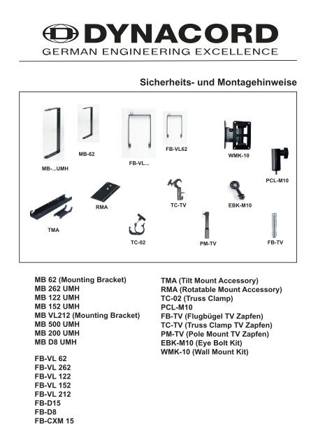
MB-...UMH<br />
TMA<br />
MB 62 (Mounting Bracket)<br />
MB 262 UMH<br />
MB 122 UMH<br />
MB 152 UMH<br />
MB VL212 (Mounting Bracket)<br />
MB 500 UMH<br />
MB 200 UMH<br />
MB D8 UMH<br />
FB-VL 62<br />
FB-VL 262<br />
FB-VL 122<br />
FB-VL 152<br />
FB-VL 212<br />
FB-D15<br />
FB-D8<br />
FB-CXM 15<br />
MB-62<br />
RMA<br />
<strong>Sicherheits</strong>- <strong>und</strong> <strong>Montagehinweise</strong><br />
FB-VL...<br />
TC-02<br />
FB-VL62<br />
TC-TV<br />
PM-TV<br />
WMK-10<br />
EBK-M10<br />
PCL-M10<br />
FB-TV<br />
TMA (Tilt Mount Accessory)<br />
RMA (Rotatable Mount Accessory)<br />
TC-02 (Truss Clamp)<br />
PCL-M10<br />
FB-TV (Flugbügel TV Zapfen)<br />
TC-TV (Truss Clamp TV Zapfen)<br />
PM-TV (Pole Mount TV Zapfen)<br />
EBK-M10 (Eye Bolt Kit)<br />
WMK-10 (Wall Mount Kit)
Allgemeine <strong>Sicherheits</strong>hinweise<br />
Montagezubehör von <strong>Dynacord</strong> Lautsprechersystemen darf ausschließlich unter Beachtung der Montageanleitung <strong>und</strong> gemäß den<br />
BGV C1-Vorschriften eingesetzt werden.<br />
Um <strong>Sicherheits</strong>kriterien einzuhalten wird ausdrücklich darauf hingewiesen, dass bei nicht Einhaltung der Montageanleitung,<br />
Veränderungen jeglicher Art des Zubehörs sowie das Montieren des Zubehörs an Systeme anderer Hersteller eine Überbelastung<br />
hervorgerufen werden kann.<br />
Alle Komponenten dürfen nur in der vorgeschriebenen Weise verb<strong>und</strong>en <strong>und</strong> so verwendet werden.<br />
Allgemeine <strong>Montagehinweise</strong><br />
Zur Befestigung an Traversen, Decken, Wänden etc. sind Befestigungsmittel mit ausreichender Dimensionierung zu verwenden<br />
(DIN 18800)<br />
Solche Montagen sind von einer sachk<strong>und</strong>igen Person auszuführen. Für alle Verschraubungen sind die vorgegebenen<br />
Maximalwerte für die Anzugsmomente einzuhalten (DIN 898).<br />
Sicherungsmaßnahmen<br />
Boxensysteme sind laut GUV 6.15 (BGV C1) im Bereich einer Bühne oder Studios gegen Um- <strong>und</strong> Herabfallen zu sichern.<br />
Dies muss unter Zuhilfenahme von Stahlseilen „(Safeties)“ bzw. Ketten, die für diese Last dimensioniert sind, geschehen.<br />
Eine Verwendung von kunststoffummantelten Drahtseilen ist ausdrücklich nicht zulässig. Die in den Vorschriften festgelegten<br />
Sicherungen sowie die maximale Fallhöhe von 20cm sind einzuhalten.<br />
Gefl ogene Lautsprecher müssen immer gegen Herabfallen bzw. Umfallen mit einem zusätzlichen, unabhängigen Punkt gesichert<br />
werden. Dies geschieht z.B. mit einem ausreichend dimensionierten Stahlseil „(Safety)“.<br />
<strong>Sicherheits</strong>faktoren<br />
Zubehör zur Befestigung von Lautsprecherboxen <strong>und</strong> Beschallungssystemen sind sicherheitsrelevante Teile, die bei Versagen<br />
Leben <strong>und</strong> Ges<strong>und</strong>heit von Menschen gefährden können. Deshalb wurden folgende Richtlinien verfasst, deren <strong>Sicherheits</strong>faktoren<br />
einzuhalten sind. Diese sind aufgr<strong>und</strong> von Verschleiß, Dauerbelastung etc. so hoch angelegt, dass auch nach jahrelangem Betrieb<br />
noch eine sichere Handhabung gewährleistet werden kann. Leider lassen sich viele Vorschriften im Bezug auf <strong>Sicherheits</strong>faktoren<br />
nicht immer eindeutig zuordnen <strong>und</strong> teilweise werden sie länderspezifi sch gehandhabt.<br />
Diverse Normen legen die <strong>Sicherheits</strong>faktoren fest:<br />
Tabelle laut der BGV C1: <strong>Sicherheits</strong>faktor<br />
Ketten, Seile, Schäkel, Ringösen,<br />
Gurte, Haken Faktor 12<br />
Zubehör <strong>und</strong> deren<br />
Verbindungselemente im mobilen<br />
Einsatz<br />
Zubehör <strong>und</strong> deren<br />
Verbindungselemente für<br />
Festinstallation<br />
Faktor 10<br />
Faktor 5<br />
Die Belastbarkeitsangaben von Herstellern handelsüblicher Trag- <strong>und</strong> Anschlagmittel beinhalten üblicherweise einen anderen<br />
<strong>Sicherheits</strong>faktor als der in den Bühnen <strong>und</strong> Studiobereichen geforderten.<br />
Tabelle laut DIN 292-2:<br />
Anschlagmittel <strong>Sicherheits</strong>faktor<br />
Drahtseile Faktor 5<br />
Ketten aus verschweißten Gliedern Faktor 4<br />
Textilfasergurte Faktor 7<br />
Metallteile Faktor 4<br />
Prüfung <strong>und</strong> Wartung<br />
Aus sicherheitstechnischen Gründen ist eine regelmäßige Überprüfung der Zubehörteile unumgänglich.<br />
Vor jedem Betrieb sollte eine Sichtprüfung vorgenommen werden. Dabei ist auf Verschleiß, Verformung, Kerben, Risse <strong>und</strong><br />
Korrosion zu achten. Bei Auftreten von Schäden am Zubehör muss dieses umgehend ausgetauscht werden.<br />
In vielen Staaten ist die regelmäßige Überprüfung von Befestigungs- <strong>und</strong> Zubehörteilen vorgeschrieben. Es empfi ehlt sich daher<br />
eine jährliche Überprüfung laut BGV C1 durch sachk<strong>und</strong>iges Fachpersonal <strong>und</strong> zusätzlich alle 4 Jahre von einem beglaubigten<br />
Sachverständigen durchführen zu lassen. Wichtig in diesem Zusammenhang ist das Führen eines Prüfbuches. In diesem werden<br />
alle Zubehörteile mit ihren Daten <strong>und</strong> der wiederkehrenden Prüfung eingetragen <strong>und</strong> sind somit jederzeit für evtl. Kontrollen<br />
einzusehen.<br />
2<br />
User Supplied<br />
Safety Cable
CABINET DUST - EYEBOLT WALL - U- MOUNT UMH- MOUNT TILT - ROTOR BRACKET FB > fix TRUSS FB > fix STAND FB > variable<br />
FB > FB ><br />
FB-TV<br />
Order-# COVER KIT 3pcs. MOUNT BRACKET BRACKET ANGLE PLATE > TRUSS TRUSS CLAMP STAND ADAPTER TRUSS/STAND TRUSS STAND<br />
PM-TV<br />
D112942<br />
TC-TV<br />
D112941<br />
FB-TV<br />
D113142<br />
FB-VL62<br />
D113140<br />
PCL M10<br />
D113116<br />
FB-VL62<br />
D113140<br />
TC-02<br />
D112808<br />
FB-VL62<br />
D113140<br />
TC-02<br />
D112808<br />
----- ----- -----<br />
MB 62<br />
D113138<br />
WMK-10<br />
D113137<br />
EBK M10<br />
D113155<br />
SH-VL62<br />
D113145<br />
VL 62<br />
D113127<br />
PM-TV<br />
D112942<br />
TC-TV<br />
D112941<br />
FB-TV<br />
D113142<br />
FB-VL262<br />
D113110<br />
PCL M10<br />
D113116<br />
FB-VL62<br />
D113140<br />
TC-02<br />
D112808<br />
FB-VL262<br />
D113110<br />
TC-02<br />
D112808<br />
RMA<br />
D112807<br />
TMA<br />
D112815<br />
MB 262 UMH<br />
D113113<br />
-----<br />
WMK-10<br />
D113137<br />
EBK M10<br />
D113155<br />
SH-VL262<br />
D113117<br />
VL 262<br />
D113101<br />
PM-TV<br />
D112942<br />
TC-TV<br />
D112941<br />
FB-TV<br />
D113142<br />
FB-VL122<br />
D113111<br />
PCL M10<br />
D113116<br />
FB-VL122<br />
D113111<br />
TC-02<br />
D112808<br />
FB-VL122<br />
D113111<br />
TC-02<br />
D112808<br />
RMA<br />
D112807<br />
TMA<br />
D112815<br />
MB 122 UMH<br />
D113114<br />
----- -----<br />
EBK M10<br />
D113155<br />
SH-VL122<br />
D113118<br />
VL 122<br />
D113103<br />
PM-TV<br />
D112942<br />
TC-TV<br />
D112941<br />
FB-TV<br />
D113142<br />
FB-VL152<br />
D113112<br />
PCL M10<br />
D113116<br />
FB-VL152<br />
D113112<br />
TC-02<br />
D112808<br />
FB-VL152<br />
D113112<br />
TC-02<br />
D112808<br />
RMA<br />
D112807<br />
TMA<br />
D112815<br />
MB 152 UMH<br />
D113115<br />
----- -----<br />
EBK M10<br />
D113155<br />
SH-VL152<br />
D113119<br />
VL 152<br />
D113104<br />
PM-TV<br />
D112942<br />
TC-TV<br />
D112941<br />
FB-TV<br />
D113142<br />
FB-VL212<br />
D113152<br />
PCL M10<br />
D113116<br />
FB-VL212<br />
D113152<br />
TC-02<br />
D112808<br />
FB-VL212<br />
D113152<br />
TC-02<br />
D112808<br />
----- ----- -----<br />
MB-VL212<br />
D113153<br />
-----<br />
EBK M10<br />
D113155<br />
SH-VL212<br />
D113147<br />
VL 212<br />
D113133<br />
PM-TV<br />
D112942<br />
TC-TV<br />
D112941<br />
FB-TV<br />
D113142<br />
FB-D8<br />
D113136<br />
PCL M10<br />
D113116<br />
FB-D8<br />
D113136<br />
TC-02<br />
D112808<br />
FB-D8<br />
D113136<br />
TC-02<br />
D112808<br />
RMA<br />
D112807<br />
TMA<br />
D112815<br />
MB D8 UMH<br />
D113135<br />
-----<br />
WMK-10<br />
D113137<br />
-----<br />
SH-D8<br />
D113143<br />
D 8<br />
D113126<br />
3<br />
----- ----- ----- ----- ----- ----- ----- -----<br />
TC-02<br />
D112808<br />
RMA<br />
D112807<br />
TMA<br />
D112815<br />
MB 200 UMH<br />
D170183<br />
----- ----- -----<br />
SH-D12<br />
D113046<br />
D 12<br />
D113030<br />
----- ----- ----- ----- ----- ----- ----- -----<br />
TC-02<br />
D112808<br />
RMA<br />
D112807<br />
TMA<br />
D112815<br />
MB 200 UMH<br />
D170183<br />
----- ----- -----<br />
SH-D12<br />
D113046<br />
D 12A<br />
D113164<br />
----- ----- ----- ----- ----- ----- ----- -----<br />
TC-02<br />
D112808<br />
RMA<br />
D112807<br />
TMA<br />
D112815<br />
MB 200 UMH<br />
D170183<br />
----- ----- -----<br />
SH-D12<br />
D113046<br />
D 12R<br />
D121941<br />
----- ----- ----- ----- ----- ----- ----- -----<br />
TC-02<br />
D112808<br />
RMA<br />
D112807<br />
TMA<br />
D112815<br />
MB 200 UMH<br />
D170183<br />
----- ----- -----<br />
SH-D12<br />
D113046<br />
D 12T<br />
D121939<br />
----- ----- ----- ----- ----- ----- ----- -----<br />
TC-02<br />
D112808<br />
RMA<br />
D112807<br />
TMA<br />
D112815<br />
MB 200 UMH<br />
D170183<br />
----- ----- -----<br />
SH-D12<br />
D113046<br />
D 12-3<br />
D113083<br />
----- ----- ----- ----- ----- ----- ----- -----<br />
TC-02<br />
D112808<br />
RMA<br />
D112807<br />
TMA<br />
D112815<br />
MB 200 UMH<br />
D170183<br />
----- ----- -----<br />
SH-D12<br />
D113046<br />
D 12-3A<br />
D113165<br />
PM-TV<br />
D112942<br />
TC-TV<br />
D112941<br />
FB-TV<br />
D113142<br />
FB-D15<br />
D113100<br />
PCL M10<br />
D113116<br />
FB-D15<br />
D113100<br />
TC-02<br />
D112808<br />
FB-D15<br />
D113100<br />
TC-02<br />
D112808<br />
RMA<br />
D112807<br />
TMA<br />
D112815<br />
MB 500 UMH<br />
D113099<br />
----- -----<br />
EBK M10<br />
D113155<br />
SH-D15<br />
D113097<br />
D 15-3<br />
D113084<br />
PM-TV<br />
D112942<br />
TC-TV<br />
D112941<br />
FB-TV<br />
D113142<br />
FB-CXM 15<br />
D113299<br />
PCL M10<br />
D113116<br />
FB-CXM 15<br />
D113299<br />
TC-02<br />
D112808<br />
FB-CXM 15<br />
D113299<br />
----- ----- ----- ----- ----- ----- ----- -----<br />
CXM 15<br />
F.01U.123.934
MB 62 (Mounting Bracket)<br />
Einfacher Wand- <strong>und</strong> Deckenmontagebügel für VL 62, ohne<br />
Neigeeinrichtung.<br />
Nicht mit TMA <strong>und</strong> RMA kombinierbar.<br />
Falls geneigter Einbau benötigt wird muss hierzu der WMK-<br />
10 verwendet werden.<br />
Montageanleitung:<br />
Die einschlägigen Montagevorschriften an Decken, Wänden<br />
oder Trägern sind unbedingt zu beachten.<br />
1. MB 62 mit geeignetem Befestigungsmaterial an<br />
Wand- oder Decke montieren.<br />
2. Die Plastikabdeckungen der benötigten M10<br />
Gewindeeinsätze an der Box entfernen.<br />
3. Die Schaftschrauben aus den Gewindeeinsätzen<br />
herausschrauben.<br />
4. Beiliegende Gummischeibe zwischen Bügel <strong>und</strong><br />
Box einlegen. Montagebügel mit Schraube M10 <strong>und</strong><br />
Scheibe an der Box verschrauben.<br />
Schrauben mit Schraubensicherungslack sichern.<br />
Schrauben festziehen.<br />
MB 262 UMH<br />
Wandmontagebügel für VL262.<br />
Zusammen mit dem TMA können Neigungswinkel zwischen<br />
5° <strong>und</strong> 45° in 5° Schritten fest eingestellt werden. Eine<br />
Ausrichtung auf die Zuhörer bei Einwärtsdrehung zur Wand<br />
wird zusätzlich mit dem RMA realisiert.<br />
Montageanleitung:<br />
Die einschlägigen Montagevorschriften an Decken, Wänden<br />
oder Trägern sind unbedingt zu beachten.<br />
1. MB 262 UMH mit geeignetem Befestigungsmaterial<br />
an Wand- oder Decke montieren.<br />
2. Die Plastikabdeckungen der benötigten M10<br />
Gewindeeinsätze an der Box entfernen.<br />
3. Die Schaftschrauben aus den Gewindeeinsätzen<br />
herausschrauben.<br />
4. Beiliegende Gummischeibe zwischen Bügel <strong>und</strong><br />
Box einlegen. Montagebügel mit Schraube M10 <strong>und</strong><br />
Scheibe an der Box verschrauben.<br />
Schrauben mit Schraubensicherungslack sichern.<br />
Schrauben festziehen.<br />
4<br />
MB 62 (Mounting Bracket)<br />
D113138<br />
MB 262 UMH<br />
D113113
MB 122 UMH<br />
Wandmontagebügel für VL 122<br />
Zusammen mit dem TMA können Neigungswinkel zwischen<br />
5° <strong>und</strong> 45° in 5° Schritten fest eingestellt werden. Eine<br />
Ausrichtung auf die Zuhörer bei Einwärtsdrehung zur Wand<br />
wird zusätzlich mit dem RMA realisiert.<br />
Montageanleitung:<br />
Die einschlägigen Montagevorschriften an Decken, Wänden<br />
oder Trägern sind unbedingt zu beachten.<br />
1. MB 122 UMH mit geeignetem Befestigungsmaterial<br />
an Wand- oder Decke montieren.<br />
2. Die Plastikabdeckungen der benötigten M10<br />
Gewindeeinsätze an der Box entfernen.<br />
3. Die Schaftschrauben aus den Gewindeeinsätzen<br />
herausschrauben.<br />
4. Beiliegende Gummischeibe zwischen Bügel <strong>und</strong><br />
Box einlegen. Montagebügel mit Schraube M10 <strong>und</strong><br />
Scheibe an der Box verschrauben.<br />
Schrauben mit Schraubensicherungslack sichern.<br />
Schrauben festziehen.<br />
MB 152 UMH<br />
Wandmontagebügel für VL 152<br />
Zusammen mit dem TMA können Neigungswinkel zwischen<br />
5° <strong>und</strong> 45° in 5° Schritten fest eingestellt werden. Eine<br />
Ausrichtung auf die Zuhörer bei Einwärtsdrehung zur Wand<br />
wird zusätzlich mit dem RMA realisiert.<br />
Montageanleitung:<br />
Die einschlägigen Montagevorschriften an Decken, Wänden<br />
oder Trägern sind unbedingt zu beachten.<br />
1. MB 152 UMH mit geeignetem Befestigungsmaterial<br />
an Wand- oder Decke montieren.<br />
2. Die Plastikabdeckungen der benötigten M10<br />
Gewindeeinsätze an der Box entfernen.<br />
3. Die Schaftschrauben aus den Gewindeeinsätzen<br />
herausschrauben.<br />
4. Beiliegende Gummischeibe zwischen Bügel <strong>und</strong><br />
Box einlegen. Montagebügel mit Schraube M10 <strong>und</strong><br />
Scheibe an der Box verschrauben.<br />
Schrauben mit Schraubensicherungslack sichern.<br />
Schrauben festziehen.<br />
5<br />
MB 122 UMH<br />
D113114<br />
MB 152 UMH<br />
D113115
MB VL212 (Mounting Bracket)<br />
Wandmontagebügel für VL 212<br />
Nicht mit TMA <strong>und</strong> RMA kombinierbar.<br />
Montageanleitung:<br />
Die einschlägigen Montagevorschriften an Decken, Wänden<br />
oder Trägern sind unbedingt zu beachten.<br />
1. MB VL212 mit geeignetem Befestigungsmaterial<br />
an Wand- oder Decke montieren.<br />
2. Die Plastikabdeckungen der benötigten M10<br />
Gewindeeinsätze an der Box entfernen.<br />
3. Die Schaftschrauben aus den Gewindeeinsätzen<br />
herausschrauben.<br />
4. Beiliegende Gummischeibe zwischen Bügel <strong>und</strong><br />
Box einlegen. Montagebügel mit Schraube M10 <strong>und</strong><br />
Scheibe an der Box verschrauben.<br />
Schrauben mit Schraubensicherungslack sichern.<br />
Schrauben festziehen.<br />
6<br />
MB VL212<br />
D113153
Wandmontagebügel für D 8<br />
MB D8 UMH<br />
Zusammen mit dem TMA können Neigungswinkel zwischen<br />
5° <strong>und</strong> 45° in 5° Schritten fest eingestellt werden. Eine<br />
Ausrichtung auf die Zuhörer bei Einwärtsdrehung zur Wand<br />
wird zusätzlich mit dem RMA realisiert.<br />
Montageanleitung:<br />
Die einschlägigen Montagevorschriften an Decken, Wänden<br />
oder Trägern sind unbedingt zu beachten.<br />
1. MB D8 UMH mit geeignetem Befestigungsmaterial<br />
an Wand- oder Decke montieren.<br />
2. Die Plastikabdeckungen der benötigten M8<br />
Gewindeeinsätze an der Box entfernen.<br />
3. Beiliegende Gummischeibe zwischen Bügel <strong>und</strong><br />
Box einlegen. Montagebügel mit Schraube M8 <strong>und</strong><br />
Scheibe an der Box verschrauben.<br />
Schrauben mit Schraubensicherungslack sichern.<br />
Schrauben festziehen.<br />
MB 200 UMH<br />
Wandmontagebügel für alle D12 Boxen<br />
Zusammen mit dem TMA können Neigungswinkel zwischen<br />
5° <strong>und</strong> 45° in 5° Schritten fest eingestellt werden. Eine<br />
Ausrichtung auf die Zuhörer bei Einwärtsdrehung zur Wand<br />
wird zusätzlich mit dem RMA realisiert.<br />
Montageanleitung:<br />
Die einschlägigen Montagevorschriften an Decken, Wänden<br />
oder Trägern sind unbedingt zu beachten.<br />
1. MB 200 UMH mit geeignetem Befestigungsmaterial<br />
an Wand- oder Decke montieren.<br />
2. Füsse der D12 Box abschrauben, Schrauben<br />
nach Abnahme der Füsse wieder einschrauben.<br />
3. Die Plastikabdeckungen der benötigten M8<br />
Gewindeeinsätze an der Box entfernen.<br />
4. Beiliegende Gummischeibe zwischen Bügel <strong>und</strong><br />
Box einlegen. Montagebügel mit Schraube M8 <strong>und</strong><br />
Scheibe an der Box verschrauben.<br />
Schrauben mit Schraubensicherungslack sichern.<br />
Schrauben festziehen.<br />
7<br />
MB D8 UMH<br />
D113135<br />
MB 200 UMH<br />
D170183
Wandmontagebügel für D15-3<br />
MB 500 UMH<br />
Zusammen mit dem TMA können Neigungswinkel zwischen<br />
5° <strong>und</strong> 45° in 5° Schritten fest eingestellt werden. Eine<br />
Ausrichtung auf die Zuhörer bei Einwärtsdrehung zur Wand<br />
wird zusätzlich mit dem RMA realisiert.<br />
Montageanleitung:<br />
Die einschlägigen Montagevorschriften an Decken, Wänden<br />
oder Trägern sind unbedingt zu beachten.<br />
1. MB 500 UMH mit geeignetem Befestigungsmaterial<br />
an Wand- oder Decke montieren.<br />
2. Füsse der D15-3 Box abschrauben, Schrauben<br />
nach Abnahme der Füsse wieder einschrauben.<br />
3. Die Plastikabdeckungen der benötigten M10<br />
Gewindeeinsätze an der Box entfernen.<br />
4. Beiliegende Gummischeibe zwischen Bügel <strong>und</strong><br />
Box einlegen. Montagebügel mit Schraube M10 <strong>und</strong><br />
Scheibe an der Box verschrauben.<br />
Schrauben mit Schraubensicherungslack sichern.<br />
Schrauben festziehen.<br />
Bohrungen für geeignetes Befestigungsmaterial<br />
Achtung:<br />
Nur die Bohrungen<br />
oben <strong>und</strong> unten wie<br />
im Bild dargestellt<br />
verwenden<br />
8<br />
MB 500 UMH<br />
D113099<br />
Zur Befestigung an Traversen, Decken, Wänden<br />
etc. sind Befestigungsmittel mit ausreichender<br />
Dimensionierung zu verwenden (DIN 18800)<br />
Solche Montagen sind von einer sachk<strong>und</strong>igen<br />
Person auszuführen. Für alle Verschraubungen<br />
sind die vorgegebenen Maximalwerte für die<br />
Anzugsmomente einzuhalten (DIN 898).
Flugbügel für VL62.<br />
FB-VL62<br />
Der FB-VL62 kann für unterschiedliche<br />
Montageanforderungen jeweils mit PCL-M10, TC-02 oder<br />
FB-TV ausgerüstet werden.<br />
Montageanleitung:<br />
1. Seitliche Kunststoffkappen an der Box entfernen<br />
<strong>und</strong> aufheben. Schaftschrauben herausdrehen.<br />
2. Riffelplatten mit den mitgelieferten Schrauben<br />
auf die Box schrauben, die vorher entfernten<br />
Kappen können dabei als Zentrierhilfe verwendet<br />
werden<br />
3. Flugbügel von hinten auf die Box schieben <strong>und</strong><br />
mit den Kegelgriffen an die Box anschrauben.<br />
4. Im Einsatz immer darauf achten, dass der Flugbügel<br />
gegen Herunterfallen zusätzlich gesichert sein<br />
muss. Hierzu sollte die am Flugbügel vorhandene<br />
Ringöse benutzt werden.<br />
Flugbügel für VL262.<br />
FB-VL262<br />
Der FB-VL262 kann für unterschiedliche<br />
Montageanforderungen jeweils mit PCL-M10, TC-02 oder<br />
FB-TV ausgerüstet werden.<br />
Montageanleitung:<br />
1. Seitliche Kunststoffkappen an der Box entfernen<br />
<strong>und</strong> aufheben. Schaftschrauben herausdrehen.<br />
2. Riffelplatten mit den mitgelieferten Schrauben auf<br />
die Box schrauben, die vorher entfernten Kappen<br />
können dabei als Zentrierhilfe verwendet werden<br />
3. Flugbügel von hinten auf die Box schieben <strong>und</strong> mit<br />
den Kegelgriffen an die Box anschrauben.<br />
4. Im Einsatz immer darauf achten, dass der Flugbügel<br />
gegen Herunterfallen zusätzlich gesichert sein<br />
muss. Hierzu sollte die am Flugbügel vorhandene<br />
Ringöse benutzt werden.<br />
9<br />
FB-VL62<br />
D113140<br />
FB-VL262<br />
D113110
Flugbügel für VL122.<br />
FB-VL122<br />
Der FB-VL122 kann für unterschiedliche<br />
Montageanforderungen jeweils mit PCL-M10, TC-02 oder<br />
FB-TV ausgerüstet werden.<br />
Montageanleitung:<br />
1. Seitliche Kunststoffkappen an der Box entfernen<br />
<strong>und</strong> aufheben. Schaftschrauben herausdrehen.<br />
2. Riffelplatten mit den mitgelieferten Schrauben auf<br />
die Box schrauben, die vorher entfernten Kappen<br />
können dabei als Zentrierhilfe verwendet werden<br />
3. Flugbügel von hinten auf die Box schieben <strong>und</strong> mit<br />
den Kegelgriffen an die Box anschrauben.<br />
4. Im Einsatz immer darauf achten, dass der Flugbügel<br />
gegen Herunterfallen zusätzlich gesichert sein<br />
muss. Hierzu sollte die am Flugbügel vorhandene<br />
Ringöse benutzt werden.<br />
Flugbügel für VL152.<br />
FB-VL152<br />
Der FB-VL152 kann für unterschiedliche<br />
Montageanforderungen jeweils mit PCL-M10, TC-02 oder<br />
FB-TV ausgerüstet werden.<br />
Montageanleitung:<br />
1. Seitliche Kunststoffkappen an der Box entfernen<br />
<strong>und</strong> aufheben. Schaftschrauben herausdrehen.<br />
2. Riffelplatten mit den mitgelieferten Schrauben auf<br />
die Box schrauben, die vorher entfernten Kappen<br />
können dabei als Zentrierhilfe verwendet werden<br />
3. Flugbügel von hinten auf die Box schieben <strong>und</strong> mit<br />
den Kegelgriffen an die Box anschrauben.<br />
4. Im Einsatz immer darauf achten, dass der Flugbügel<br />
gegen Herunterfallen zusätzlich gesichert sein<br />
muss. Hierzu sollte die am Flugbügel vorhandene<br />
Ringöse benutzt werden.<br />
10<br />
FB-VL122<br />
D113111<br />
FB-VL152<br />
D113112
Flugbügel für VL212.<br />
FB-VL212<br />
Der FB-VL212 kann für unterschiedliche<br />
Montageanforderungen jeweils mit PCL-M10, TC-02 oder<br />
FB-TV ausgerüstet werden.<br />
Montageanleitung:<br />
1. Seitliche Kunststoffkappen an der Box entfernen<br />
<strong>und</strong> aufheben. Schaftschrauben herausdrehen.<br />
2. Riffelplatten mit den mitgelieferten Schrauben auf<br />
die Box schrauben, die vorher entfernten Kappen<br />
können dabei als Zentrierhilfe verwendet werden<br />
3. Flugbügel von hinten auf die Box schieben <strong>und</strong> mit<br />
den Kegelgriffen an die Box anschrauben.<br />
4. Im Einsatz immer darauf achten, dass der Flugbügel<br />
gegen Herunterfallen zusätzlich gesichert sein<br />
muss. Hierzu sollte die am Flugbügel vorhandene<br />
Ringöse benutzt werden.<br />
Flugbügel für CXM 15.<br />
FB-CXM 15<br />
Der FB-CXM 15 kann für unterschiedliche<br />
Montageanforderungen jeweils mit PCL-M10, TC-02 oder<br />
FB-TV ausgerüstet werden.<br />
Montageanleitung:<br />
1. Seitliche Abdeckschrauben, (siehe Abb.) an der<br />
Box entfernen <strong>und</strong> aufheben.<br />
2. Flugbügel auf die Box schieben <strong>und</strong> mit den<br />
Kegelgriffen an die Box anschrauben.<br />
3. Im Einsatz immer darauf achten, dass der Flugbügel<br />
gegen Herunterfallen zusätzlich gesichert sein<br />
muss. Hierzu sollte die am Flugbügel vorhandene<br />
Ringöse benutzt werden.<br />
11<br />
FB-VL212<br />
D113152<br />
FB-CXM 15<br />
D113299
Flugbügel für D8<br />
Flugbügel für D15-3<br />
FB-D15<br />
Der FB-D15 kann für unterschiedliche<br />
Montageanforderungen jeweils mit PCL-M10, TC-02 oder<br />
FB-TV ausgerüstet werden.<br />
Montageanleitung:<br />
FB-D8<br />
Der FB-D8 kann für unterschiedliche Montageanforderungen<br />
jeweils mit PCL-M10, TC-02 oder FB-TV ausgerüstet<br />
werden.<br />
Montageanleitung:<br />
1. Seitliche Kunststoffkappen an der Box entfernen<br />
<strong>und</strong> aufheben.<br />
2. Flugbügel von hinten auf die Box schieben <strong>und</strong> mit<br />
den Kegelgriffen an die Box anschrauben.<br />
3. Im Einsatz immer darauf achten, dass der Flugbügel<br />
gegen Herunterfallen zusätzlich gesichert sein<br />
muss. Hierzu sollte die am Flugbügel vorhandene<br />
Ringöse benutzt werden.<br />
12<br />
FB-D8<br />
D113136<br />
FB-D15<br />
D113100
TMA (Tilt Mount Accessory)<br />
Wandhalterung für die Wandmontagebügel MB….UMH. Die<br />
Neigung kann zwischen 5° <strong>und</strong> 45° in 5° Schritten fest eingestellt<br />
werden.<br />
Eine Ausrichtung auf die Zuhörer bei Einwärtsdrehung zur Wand<br />
wird zusätzlich mit dem RMA realisiert.<br />
Montageanleitung:<br />
Die einschlägigen Montagevorschriften an Decken, Wänden oder<br />
Trägern sind unbedingt zu beachten.<br />
1. Wandhalterung mit geeigneten Schrauben <strong>und</strong> Dübeln<br />
(10mm Durchmesser) an der Wand befestigen.<br />
2. Schrägsteller montieren<br />
3. Wandmontagebügel an Box montieren.<br />
4. Box mit Wandmontagebügel in den TMA unten<br />
einhängen.<br />
5. Sicherungsschraube einführen <strong>und</strong> sofort verschrauben.<br />
6. Neigungswinkel einstellen, anschliessend Schrauben fest<br />
anziehen.<br />
RMA (Rotatable Mount<br />
Accessory)<br />
Rotorplatte zum TMA <strong>und</strong> den Wandmontagebügeln MB…UMH<br />
zur Ausrichtung einwärts gedrehter Boxen auf die Zuhörer.<br />
Vertikaler Drehwinkel 45°, verstellbar in 5° Schritten.<br />
Montageanleitung:<br />
Die einschlägigen Montagevorschriften an Decken, Wänden oder<br />
Trägern sind unbedingt zu beachten.<br />
1. RMA mit 6 Schrauben <strong>und</strong> Dübeln (10mm<br />
Durchmesser) an der Wand befestigen.<br />
2. TMA auf RMA aufsetzen <strong>und</strong> mit beiliegender<br />
selbstsichender Mutter anschrauben.<br />
3. Gewünschten Drehwinkel einstellen <strong>und</strong> mit<br />
Arretierschraube fi xieren. Schrauben festziehen.<br />
4. Wandmontagebügel an Box montieren..<br />
5. Wandmontagebügel in den TMA einsetzen <strong>und</strong> sofort die<br />
Sicherungsschraube einführen.<br />
6. Box ausrichten.<br />
7. Alle Schrauben festziehen.<br />
13<br />
TMA (Tilt Mount Accessory)<br />
D112815<br />
RMA (Rotatable Mount Accessory)<br />
D112807
TC-02 (Truss Clamp)<br />
Klammer zur direkten Befestigung der Flugbügel FB-<strong>und</strong> MB an<br />
Rohrgerüsten (Truss).<br />
Montageanleitung:<br />
1. TC-02 mit zugehöriger M10 Schraube, Sicherungsblech,<br />
Mutter <strong>und</strong> Unterlegscheibe am Flugbügel montieren.<br />
Das Sicherungsblech muss zwischen M10 Schraube <strong>und</strong><br />
Trussklemme angebracht werden.<br />
Die Unterlegscheibe muss zwischen Mutter <strong>und</strong> Bügel<br />
angebracht werden.<br />
2. Schraube <strong>und</strong> Mutter festziehen.<br />
PCL M10<br />
Adapter mit M10 Gewindebolzen zur Verwendung mit<br />
den FB… Flugbügeln auf Boxenhochständern mit 35mm<br />
Flanschdurchmesser. Der PCL M10 kann auch für Boxen mit M10<br />
Gewindeeinsätzen als Hochständerhülse eingesetzt werden.<br />
Montageanleitung:<br />
1. PCL M10 mit M10 Mutter <strong>und</strong> Sicherungsscheibe am<br />
Flugbügel befestigen.<br />
2. Die Sicherungsscheibe muss zwischen Mutter <strong>und</strong><br />
Flugbügel angebracht werden.<br />
3. Mutter festziehen.<br />
14<br />
TC-02 (Truss Clamp)<br />
D112808<br />
PCL M10<br />
D113116
FB-TV (Flugbügel TV Zapfen)<br />
TV Zapfen für die FB-… Flugbügel zur Verwendung mit<br />
geeigneten Leuchtenstativen oder mit PM-TV auf geeigneten<br />
Lautsprecherstativ. Mit Trussklammern (TC-TV) die für die<br />
Aufnahme von TV Zapfen vorbereitet sind.<br />
Montageanleitung:<br />
1. FB-TV mit M10 Schraube <strong>und</strong> Sicherungsscheibe am<br />
Flugbügel befestigen.<br />
2. Die Sicherungsscheibe muss zwischen Schraube <strong>und</strong><br />
Flugbügel angebracht werden.<br />
3. Schraube festziehen.<br />
TC-TV (Truss Clamp TV Zapfen)<br />
Klammer für Rohrgerüste (Truss) mit Aufnahme für TV Zapfen<br />
(FB-TV).<br />
Montageanleitung:<br />
1. TC-TV Klammer auf den TV Zapfen (FB-TV) aufsetzen.<br />
2. Sicherungsstift durch das Sicherungsloch führen <strong>und</strong><br />
durch Abknicken des Sicherunsstiftes sichern.<br />
3. Die Feststellschraube des TC-TV festziehen.<br />
15<br />
FB-TV (Flugbügel TV Zapfen)<br />
D113142<br />
TC-TV (Truss clamp TV Zapfen)<br />
D112941
PM-TV (Pole Mount TV Zapfen)<br />
Adapter für die Verwendung von Flugbügeln mit TV Zapfen<br />
auf Stativen wie K&M 213 (König&Meyer) oder Modellen<br />
mit gleicher M10 Gewindeaufnahme <strong>und</strong> gleichem 35mm<br />
Flanschdurchmesser. Innenliegender M10 Schraubbolzen.<br />
Montageanleitung:<br />
1. PM-TV auf den Hochständerfl ansch des Hochständers<br />
aufsetzen <strong>und</strong> durch Drehen verschrauben.<br />
2. TV Zapfen FB-TV in den PM-TV Adapter einführen <strong>und</strong><br />
mit dem Feststellknebel sichern.<br />
EBK M10 (Eye Bolt Kit M10)<br />
Ringösensatz zur Boxenmontage mit Ketten oder Seilen.<br />
Montageanleitung:<br />
Aus <strong>Sicherheits</strong>gründen muss die Aufhängung an mindestens<br />
3 Gewindeeinsätzen in der Box erfolgen. Die einschlägigen<br />
Montagevorschriften an Decken, Wänden oder Trägern sind<br />
unbedingt zu beachten.<br />
1. Die Plastikabdeckungen der benötigten M10<br />
Gewindeeinsätze an der Box entfernen.<br />
2. Die Schaftschrauben aus den Gewindeeinsätzen<br />
herausschrauben.<br />
3. Ringösen mit Schraubensicherungslack einschrauben<br />
<strong>und</strong> von aussen mit den Kontermuttern gegen Verdrehen<br />
sichern.<br />
16<br />
PM-TV (Pole Mount TV Zapfen)<br />
D112942<br />
EBK M10 (Eye Bolt Kit M10)<br />
D113155
WMK 10 (Wall Mount Kit)<br />
Wandhalterung für VL62 <strong>und</strong> VL262 <strong>und</strong> andere Kleinboxen bis<br />
zu 15kg. Universaladapterplatte für Standard 4-Punkt Montage.<br />
In Richtung <strong>und</strong> Neigung verstellbar. Bis zu 30° vertikaler<br />
Neigungswinkel.<br />
Montageanleitung:<br />
Die einschlägigen Montagevorschriften an Decken, Wänden oder<br />
Trägern sind unbedingt zu beachten.<br />
1. Neigebügel mit Adapterplatte vom Schwenkbügel der<br />
Wandhalterung abmontieren.<br />
2. Wandhalterung mit geeignetem Befestigungsmaterial an<br />
der Wand montieren.<br />
3. Box mit den 4 beiliegenden Schrauben an der<br />
Adapterplatte befestigen.<br />
4. Adapterplatte mit Neigebügel in den Schwenkbügel der<br />
Wandhalterung einhängen.<br />
5. Eingehängten Neigebügel sofort mit Schlossschraube,<br />
Unterlegscheibe <strong>und</strong> Sicherungsmutter mit dem<br />
Schwenkbügel verschrauben.<br />
6. Gewünschten Neigungswinkel durch Fixierung der<br />
oberen Verschraubung am Neigebügel einstellen.<br />
17<br />
WMK-10 (Wall Mount Kit)<br />
D113137
MB-...UMH<br />
TMA<br />
MB 62 (Mounting Bracket)<br />
MB 262 UMH<br />
MB 122 UMH<br />
MB 152 UMH<br />
MB 212 (Mounting Bracket)<br />
MB 500 UMH<br />
MB 200 UMH<br />
MB D8 UMH<br />
FB-VL 62<br />
FB-VL 262<br />
FB-VL 122<br />
FB-VL 152<br />
FB-VL 212<br />
FB-D15<br />
FB-D8<br />
FB-CXM 15<br />
MB 62<br />
RMA<br />
Safety and assembling instructions<br />
FB-VL...<br />
TC-02<br />
FB-VL62<br />
TC-TV<br />
PM-TV<br />
WMK-10<br />
EBK-M10<br />
PCL-M10<br />
FB-TV<br />
TMA (Tilt Mount Accessory)<br />
RMA (Rotatable Mount Accessory)<br />
TC-02 (Truss Clamp)<br />
PCL-M10<br />
FB-TV (Flight Bracket TV stud)<br />
TC-TV (Truss Clamp TV stud)<br />
PM-TV (Pole Mount TV stud)<br />
EBK-M10 (Eye Bolt Kit)<br />
WMK-10 (Wall Mount Kit)
General Safety References<br />
Assembly accessories of <strong>Dynacord</strong> loudspeaker systems may be used exclusively considering the assembly instruction and in<br />
accordance with the BGV C1 regulations.<br />
In order to keep the safety criteria it will be expressly pointed out that an overload can be caused in the event of non-observance<br />
of the assembly instruction, changes of any kind of the accessories as well as installing the accessories to systems of other<br />
manufacturers.<br />
All components may be connected only in the prescribed way and used in such a way.<br />
General Assembling Instructions<br />
For attachment at trusses, ceilings, walls etc. fi xing material with suffi cient ratings is to be used (DIN 18800)<br />
All such mountings are to be done by an experienced person. For all screw connections the given maximum ratings for the<br />
torques are to be kept (DIN 898).<br />
Safeguards<br />
Loudspeaker systems are to be secured within the range of a stage or studios against tilting or falling down according to GUV<br />
6.15 (BGV C1).<br />
This must happen with help of steel cables “(Safeties)” and/or chains, which are dimensioned for this working-load. A use of<br />
plastic-encased wire ropes is not permissible expressly. The safety devices specifi ed in the regulations as well as the maximum<br />
head of 20cm are to be kept.<br />
Flown loudspeakers must be secured always against falling down by an additional, independent suspension point. This happens<br />
e.g. with a suffi ciently dimensioned steel cable “(Safety)”.<br />
Safety Factors<br />
Accessories for the attachment of loudspeaker enclosures and PA systems are safety-relevant parts, which can endanger lives<br />
and health of humans during failure. Therefore the following guidelines were written, whose safety factors are to be kept. These<br />
are very highly put on due to wear, continuous stress etc. that also after use for many years still further safe handling can be<br />
ensured. Unfortunately many regulations in the reference to safety factors cannot be assigned always clearly and are often<br />
handled country-specifi cally.<br />
Various standards specify the safety factors:<br />
Table according to BGV C1: Safety factor<br />
Chains, ropes, shackles, eye bolts,<br />
belts, hooks Factor 12<br />
Accessories and their connection<br />
elements in mobile use Factor 10<br />
Accessories and their connection<br />
elements for fi xed installation Factor 5<br />
The maximum working load of manufacturers of commercial lifting and rigging hardware show usually other safety factors than<br />
demanded in thestage and studio areas.<br />
Table according to DIN 292-2:<br />
Lifting accessories Safety factor<br />
Wire ropes Factor 5<br />
Chains from welded links Factor 4<br />
Textile fi ber belts Factor 7<br />
Metal parts Factor 4<br />
Inspection and Maintenance<br />
For safety-relevant reasons a regular inspection of the accessories is inevitable.<br />
Prior to each use inspect the loudspeaker enclosures for any wear, deformation, notches, cracks and corrosion. Replace any<br />
damaged accessories immediately.<br />
In many states the regular inspection of attachment and accessories is prescribed. It is advisable to accomplish an annual<br />
inspection according to BGV C1 every 4 years by experienced technical personnel and additionally of a certifi ed expert. In this<br />
connection<br />
leading of a test book is important, in which all accessories with their data and the recurring inspection are registered and are<br />
thus available at any time for potential controls.<br />
20<br />
User Supplied<br />
Safety Cable
CABINET DUST - EYEBOLT WALL - U- MOUNT UMH- MOUNT TILT - ROTOR BRACKET FB > fix TRUSS FB > fix STAND FB > variable<br />
FB > FB ><br />
FB-TV<br />
Order-# COVER KIT 3pcs. MOUNT BRACKET BRACKET ANGLE PLATE > TRUSS TRUSS CLAMP STAND ADAPTER TRUSS/STAND TRUSS STAND<br />
PM-TV<br />
D112942<br />
TC-TV<br />
D112941<br />
FB-TV<br />
D113142<br />
FB-VL62<br />
D113140<br />
PCL M10<br />
D113116<br />
FB-VL62<br />
D113140<br />
TC-02<br />
D112808<br />
FB-VL62<br />
D113140<br />
TC-02<br />
D112808<br />
----- ----- -----<br />
MB 62<br />
D113138<br />
WMK-10<br />
D113137<br />
EBK M10<br />
D113155<br />
SH-VL62<br />
D113145<br />
VL 62<br />
D113127<br />
PM-TV<br />
D112942<br />
TC-TV<br />
D112941<br />
FB-TV<br />
D113142<br />
FB-VL262<br />
D113110<br />
PCL M10<br />
D113116<br />
FB-VL62<br />
D113140<br />
TC-02<br />
D112808<br />
FB-VL262<br />
D113110<br />
TC-02<br />
D112808<br />
RMA<br />
D112807<br />
TMA<br />
D112815<br />
MB 262 UMH<br />
D113113<br />
-----<br />
WMK-10<br />
D113137<br />
EBK M10<br />
D113155<br />
SH-VL262<br />
D113117<br />
VL 262<br />
D113101<br />
PM-TV<br />
D112942<br />
TC-TV<br />
D112941<br />
FB-TV<br />
D113142<br />
FB-VL122<br />
D113111<br />
PCL M10<br />
D113116<br />
FB-VL122<br />
D113111<br />
TC-02<br />
D112808<br />
FB-VL122<br />
D113111<br />
TC-02<br />
D112808<br />
RMA<br />
D112807<br />
TMA<br />
D112815<br />
MB 122 UMH<br />
D113114<br />
----- -----<br />
EBK M10<br />
D113155<br />
SH-VL122<br />
D113118<br />
VL 122<br />
D113103<br />
PM-TV<br />
D112942<br />
TC-TV<br />
D112941<br />
FB-TV<br />
D113142<br />
FB-VL152<br />
D113112<br />
PCL M10<br />
D113116<br />
FB-VL152<br />
D113112<br />
TC-02<br />
D112808<br />
FB-VL152<br />
D113112<br />
TC-02<br />
D112808<br />
RMA<br />
D112807<br />
TMA<br />
D112815<br />
MB 152 UMH<br />
D113115<br />
----- -----<br />
EBK M10<br />
D113155<br />
SH-VL152<br />
D113119<br />
VL 152<br />
D113104<br />
PM-TV<br />
D112942<br />
TC-TV<br />
D112941<br />
FB-TV<br />
D113142<br />
FB-VL212<br />
D113152<br />
PCL M10<br />
D113116<br />
FB-VL212<br />
D113152<br />
TC-02<br />
D112808<br />
FB-VL212<br />
D113152<br />
TC-02<br />
D112808<br />
----- ----- -----<br />
MB-VL212<br />
D113153<br />
-----<br />
EBK M10<br />
D113155<br />
SH-VL212<br />
D113147<br />
VL 212<br />
D113133<br />
PM-TV<br />
D112942<br />
TC-TV<br />
D112941<br />
FB-TV<br />
D113142<br />
FB-D8<br />
D113136<br />
PCL M10<br />
D113116<br />
FB-D8<br />
D113136<br />
TC-02<br />
D112808<br />
FB-D8<br />
D113136<br />
TC-02<br />
D112808<br />
RMA<br />
D112807<br />
TMA<br />
D112815<br />
MB D8 UMH<br />
D113135<br />
-----<br />
WMK-10<br />
D113137<br />
-----<br />
SH-D8<br />
D113143<br />
D 8<br />
D113126<br />
21<br />
----- ----- ----- ----- ----- ----- ----- -----<br />
TC-02<br />
D112808<br />
RMA<br />
D112807<br />
TMA<br />
D112815<br />
MB 200 UMH<br />
D170183<br />
----- ----- -----<br />
SH-D12<br />
D113046<br />
D 12<br />
D113030<br />
----- ----- ----- ----- ----- ----- ----- -----<br />
TC-02<br />
D112808<br />
RMA<br />
D112807<br />
TMA<br />
D112815<br />
MB 200 UMH<br />
D170183<br />
----- ----- -----<br />
SH-D12<br />
D113046<br />
D 12A<br />
D113164<br />
----- ----- ----- ----- ----- ----- ----- -----<br />
TC-02<br />
D112808<br />
RMA<br />
D112807<br />
TMA<br />
D112815<br />
MB 200 UMH<br />
D170183<br />
----- ----- -----<br />
SH-D12<br />
D113046<br />
D 12R<br />
D121941<br />
----- ----- ----- ----- ----- ----- ----- -----<br />
TC-02<br />
D112808<br />
RMA<br />
D112807<br />
TMA<br />
D112815<br />
MB 200 UMH<br />
D170183<br />
----- ----- -----<br />
SH-D12<br />
D113046<br />
D 12T<br />
D121939<br />
----- ----- ----- ----- ----- ----- ----- -----<br />
TC-02<br />
D112808<br />
RMA<br />
D112807<br />
TMA<br />
D112815<br />
MB 200 UMH<br />
D170183<br />
----- ----- -----<br />
SH-D12<br />
D113046<br />
D 12-3<br />
D113083<br />
----- ----- ----- ----- ----- ----- ----- -----<br />
TC-02<br />
D112808<br />
RMA<br />
D112807<br />
TMA<br />
D112815<br />
MB 200 UMH<br />
D170183<br />
----- ----- -----<br />
SH-D12<br />
D113046<br />
D 12-3A<br />
D113165<br />
PM-TV<br />
D112942<br />
TC-TV<br />
D112941<br />
FB-TV<br />
D113142<br />
FB-D15<br />
D113100<br />
PCL M10<br />
D113116<br />
FB-D15<br />
D113100<br />
TC-02<br />
D112808<br />
FB-D15<br />
D113100<br />
TC-02<br />
D112808<br />
RMA<br />
D112807<br />
TMA<br />
D112815<br />
MB 500 UMH<br />
D113099<br />
----- -----<br />
EBK M10<br />
D113155<br />
SH-D15<br />
D113097<br />
D 15-3<br />
D113084<br />
PM-TV<br />
D112942<br />
TC-TV<br />
D112941<br />
FB-TV<br />
D113142<br />
FB-CXM 15<br />
D113299<br />
PCL M10<br />
D113116<br />
FB-CXM 15<br />
D113299<br />
TC-02<br />
D112808<br />
FB-CXM 15<br />
D113299<br />
----- ----- ----- ----- ----- ----- ----- -----<br />
CXM 15<br />
F.01U.123.934
MB 62 (Mounting Bracket)<br />
Simple wall and ceiling mounting bracket for VL 62, without<br />
slope mechanism.<br />
Not combinable with TMA and RMA.<br />
If bent installation is needed the WMK 10 must be used.<br />
Assembly instruction:<br />
The relevant assembly instructions at ceilings, walls or<br />
trusses are to be considered absolutely.<br />
1. Install MB 62 at the wall or ceiling with suitable<br />
mounting material.<br />
2. Remove the plastic covers of the necessary M10<br />
threaded inserts at the enclosure.<br />
3. Unscrew the shaft screws from the threaded inserts.<br />
4. Insert enclosed rubber washer between bracket<br />
and enclosure. Bolt mounting bracket together with<br />
screw M10 and disk at the enclosure. Secure<br />
screws with thread locking compo<strong>und</strong>.<br />
Tighten screws.<br />
MB 262 UMH<br />
Wall mounting bracket for VL 262.<br />
Together with the TMA inclination angles between 5° and 45°<br />
can be adjusted in 5° steps. An adjustment to the listeners<br />
direction with turn-in to the wall is realized additionally with<br />
the RMA.<br />
Assembly instruction:<br />
The relevant assembly instructions at ceilings, walls or<br />
trusses are to be considered absolutely.<br />
1. Install MB 262 UMH at the wall or ceiling with<br />
suitable mounting material.<br />
2. Remove the plastic covers of the necessary M10<br />
threaded inserts at the enclosure.<br />
3. Unscrew the shaft screws from the threaded inserts.<br />
4. Insert enclosed rubber washer between bracket<br />
and enclosure. Bolt mounting bracket together with<br />
screw M10 and disk at the enclosure. Secure<br />
screws with thread locking compo<strong>und</strong>.<br />
Tighten screws.<br />
22<br />
MB 62 (Mounting Bracket)<br />
D113138<br />
MB 262 UMH<br />
D113113
MB 122 UMH<br />
Wall mounting bracket for VL 122<br />
Together with the TMA inclination angles between 5°<br />
and 45° can be adjusted in 5° steps. An adjustment to<br />
the listeners direction with turn-in to the wall is realized<br />
additionally with the RMA.<br />
Assembly instruction:<br />
The relevant assembly instructions at ceilings, walls or<br />
booms are to be considered absolutely.<br />
1. Install MB 122 UMH at the wall or ceiling with<br />
suitable mounting material<br />
2. Remove the plastic covers of the necessary M10<br />
threaded inserts at the enclosure.<br />
3. Unscrew the shaft screws from the threaded inserts.<br />
4. Insert enclosed rubber washer between bracket<br />
and enclosure. Bolt mounting bracket together with<br />
screw M10 and disk at the enclosure. Secure<br />
screws with thread locking compo<strong>und</strong>.<br />
Tighten screws.<br />
MB 152 UMH<br />
Wall mounting bracket for VL 152<br />
Together with the TMA inclination angles between 5°<br />
and 45° can be adjusted in 5° steps. An adjustment to<br />
the listeners direction with turn-in to the wall is realized<br />
additionally with the RMA.<br />
Assembly instruction:<br />
The relevant assembly instructions at ceilings, walls or<br />
trusses are to be considered absolutely.<br />
1. Install MB 152 UMH at the wall or ceiling with<br />
suitable mounting material.<br />
2. Remove the plastic covers of the necessary M10<br />
threaded inserts at the enclosure.<br />
3. Unscrew the shaft screws from the threaded inserts.<br />
4. Insert enclosed rubber washer between bracket<br />
and enclosure. Bolt mounting bracket together with<br />
screw M10 and disk at the enclosure. Secure<br />
screws with thread locking compo<strong>und</strong>.<br />
Tighten screws.<br />
23<br />
MB 122 UMH<br />
D113114<br />
MB 152 UMH<br />
D113115
MB VL212<br />
Wall mounting bracket for VL 212<br />
Not combinable with TMA and RMA.<br />
Assembly instruction:<br />
The relevant assembly instructions at ceilings, walls or<br />
trusses are to be considered absolutely.<br />
1. Install MB VL212 at the wall or ceiling with<br />
suitable mounting material.<br />
2. Remove the plastic covers of the necessary M10<br />
threaded inserts at the enclosure.<br />
3. Unscrew the shaft screws from the threaded inserts.<br />
4. Insert enclosed rubber washer between bracket<br />
and enclosure. Bolt mounting bracket together with<br />
screw M10 and disk at the enclosure. Secure<br />
screws with thread locking compo<strong>und</strong>.<br />
Tighten screws.<br />
24<br />
MB VL212<br />
D113153
Wall mounting bracket for D8<br />
MB 200 UMH<br />
Wall mounting bracket for all D12 cabinet<br />
Together with the TMA inclination angles between 5°<br />
and 45° can be adjusted in 5° steps. An adjustment to<br />
the listeners direction with turn-in to the wall is realized<br />
additionally with the RMA.<br />
Assembly instruction:<br />
MB D8 UMH<br />
Together with the TMA inclination angles between 5°<br />
and 45° can be adjusted in 5° steps. An adjustment to<br />
the listeners direction with turn-in to the wall is realized<br />
additionally with the RMA.<br />
Assembly instruction:<br />
The relevant assembly instructions at ceilings, walls or<br />
trusses are to be considered absolutely.<br />
1. Install MB D8 UMH at the wall or ceiling with<br />
suitable mounting material.<br />
2. Remove the plastic covers of the necessary M8<br />
threaded inserts at the enclosure.<br />
3. Insert enclosed rubber washer between bracket<br />
and enclosure. Bolt mounting bracket together with<br />
screw M8 and disk at the enclosure. Secure<br />
screws with thread locking compo<strong>und</strong>.<br />
Tighten screws.<br />
The relevant assembly instructions at ceilings, walls or<br />
trusses are to be considered absolutely.<br />
1. Install MB 200 UMH at the wall or ceiling with<br />
suitable mounting material.<br />
2. Remove the feet of the D12 enclosure and insert<br />
the screws after removing the feet again.<br />
3. Remove the plastic covers of the necessary M8<br />
threaded inserts at the enclosure.<br />
4. Insert enclosed rubber washer between bracket<br />
and enclosure. Bolt mounting bracket together with<br />
screw M8 and disk at the enclosure. Secure<br />
screws with thread locking compo<strong>und</strong>.<br />
Tighten screws.<br />
25<br />
MB D8 UMH<br />
D113135<br />
MB 200 UMH<br />
D170183
MB 500 UMH<br />
Wall mounting bracket for D15-3<br />
Together with the TMA inclination angles between 5°<br />
and 45° can be adjusted in 5° steps. An adjustment to<br />
the listeners direction with turn-in to the wall is realized<br />
additionally with the RMA.<br />
Assembly instruction:<br />
The relevant assembly instructions at ceilings, walls or<br />
trusses are to be considered absolutely.<br />
1. Install MB 500 UMH at the wall or ceiling with<br />
suitable mounting material.<br />
2. Remove the feet of the D15-3 enclosure and insert<br />
the screws after removing the feet again.<br />
3. Remove the plastic covers of the necessary M10<br />
threaded inserts at the enclosure.<br />
4. Insert enclosed rubber washer between bracket<br />
and enclosure. Bolt mounting bracket together with<br />
screw M10 and disk at the enclosure. Secure<br />
screws with thread locking compo<strong>und</strong>.<br />
Tighten screws.<br />
Drillings for suitable mounting mateials<br />
CAUTION:<br />
Use upper and lower<br />
drillings only.<br />
(refer to the illustration)<br />
26<br />
MB 500 UMH<br />
D113099<br />
Use adequately dimensioned rigging<br />
equipment (DIN 18800) when connecting<br />
to crossbeams, ceiling, walls, etc.<br />
Leave all mounting and rigging to<br />
experienced personnel. Carefully abide<br />
default maximum clamping torque values<br />
for all screw joints (DIN 898).
Flight bracket for VL 62.<br />
FB-VL 62<br />
The FB-VL 62 can be equipped for different assembly<br />
requirements in each case with PCL-M10, TC-02 or FB-TV.<br />
Assembly instruction:<br />
1. Remove lateral plastic caps at the enclosure and<br />
keep it for further use. Unscrew shaft screws.<br />
2. Mount the wrinkle plates with the provided screws<br />
on the enclosure; the caps removed before can be<br />
used as a centering assistance.<br />
3. Push fl ight bracket from the rear onto the enclosure<br />
and screw it with the cone handles onto the<br />
enclosure.<br />
4. Make sure that the fl ight bracket is additionally<br />
secured against falling down during operation.<br />
For this the eye bolt mounted at the fl ight bracket<br />
should be used.<br />
Flight bracket for VL 262.<br />
FB-VL 262<br />
The FB-VL 62 can be equipped for different assembly<br />
requirements in each case with PCL-M10, TC-02 or FB-TV.<br />
Assembly instruction:<br />
1. Remove lateral plastic caps at the enclosure and<br />
keep it for further use. Unscrew shaft screws.<br />
2. Mount the wrinkle plates with the provided screws<br />
on the enclosure; the caps removed before can be<br />
used as a centering assistance.<br />
3. Push fl ight bracket from the rear onto the enclosure<br />
and screw it with the cone handles onto the<br />
enclosure.<br />
4. Make sure that the fl ight bracket is additionally<br />
secured against falling down during operation.<br />
For this the eye bolt mounted at the fl ight bracket<br />
should be used.<br />
27<br />
FB-VL62<br />
D113140<br />
FB-VL262<br />
D113110
Flight bracket for VL 122.<br />
FB-VL 122<br />
The FB-VL 122 can be equipped for different assembly<br />
requirements in each case with PCL-M10, TC-02 or FB-TV.<br />
Assembly instruction:<br />
1. Remove lateral plastic caps at the enclosure and<br />
keep it for further use. Unscrew shaft screws.<br />
2. Mount the wrinkle plates with the provided screws<br />
on the enclosure; the caps removed before can be<br />
used as a centering assistance.<br />
3. Push fl ight bracket from the rear onto the enclosure<br />
and screw it with the cone handles onto the<br />
enclosure.<br />
4. Make sure that the fl ight bracket is additionally<br />
secured against falling down during operation.<br />
For this the eye bolt mounted at the fl ight bracket<br />
should be used.<br />
Flight bracket for VL 152.<br />
FB-VL 152<br />
The FB-VL 152 can be equipped for different assembly<br />
requirements in each case with PCL-M10, TC-02 or FB-TV.<br />
Assembly instruction:<br />
1. Remove lateral plastic caps at the enclosure and<br />
keep it for further use. Unscrew shaft screws.<br />
2. Mount the wrinkle plates with the provided screws<br />
on the enclosure; the caps removed before can be<br />
used as a centering assistance.<br />
3. Push fl ight bracket from the rear onto the enclosure<br />
and screw it with the cone handles onto the<br />
enclosure.<br />
4. Make sure that the fl ight bracket is additionally<br />
secured against falling down during operation.<br />
For this the eye bolt mounted at the fl ight bracket<br />
should be used.<br />
28<br />
FB-VL122<br />
D113111<br />
FB-VL152<br />
D113112
Flight bracket for VL 212.<br />
FB-VL 212<br />
The FB-VL 212 can be equipped for different assembly<br />
requirements in each case with PCL-M10, TC-02 or FB-TV.<br />
Assembly instruction:<br />
1. Remove lateral plastic caps at the enclosure and<br />
keep it for further use. Unscrew shaft screws.<br />
2. Mount the wrinkle plates with the provided screws<br />
on the enclosure; the caps removed before can be<br />
used as a centering assistance.<br />
3. Push fl ight bracket from the rear onto the enclosure<br />
and screw it with the cone handles onto the<br />
enclosure.<br />
4. Make sure that the fl ight bracket is additionally<br />
secured against falling down during operation.<br />
For this the eye bolt mounted at the fl ight bracket<br />
should be used.<br />
Flight bracket for CXM 15..<br />
FB-CXM 15<br />
The FB-CXM 15 can be equipped for different assembly<br />
requirements in each case with PCL-M10, TC-02 or FB-TV.<br />
Assembly instruction:<br />
1. Remove lateral screws (see fi g.) at the enclosure<br />
and keep it for further use.<br />
2. Push fl ight bracket onto the enclosure and screw<br />
it with the cone handles onto the enclosure.<br />
3. Make sure that the fl ight bracket is additionally<br />
secured against falling down during operation.<br />
For this the eye bolt mounted at the fl ight bracket<br />
should be used.<br />
29<br />
FB-VL212<br />
D113152<br />
FB-CXM 15<br />
D113299
Flight bracket for D8.<br />
Flight bracket for D15-3.<br />
FB-D15<br />
The FB-D15 can be equipped for different assembly<br />
requirements in each case with PCL-M10, TC-02 or FB-TV.<br />
Assembly instruction:<br />
FB-D8<br />
The FB-D8 can be equipped for different assembly<br />
requirements in each case with PCL-M10, TC-02 or FB-TV.<br />
Assembly instruction:<br />
1. Remove lateral plastic caps at the enclosure and<br />
keep it for further use.<br />
2. Push fl ight bracket from the rear onto the enclosure<br />
and screw it with the cone handles onto the<br />
enclosure.<br />
3. Make sure that the fl ight bracket is additionally<br />
secured against falling down during operation. For<br />
this the eye bolt mounted at the fl ight bracket<br />
should be used.<br />
30<br />
FB-D8<br />
D113136<br />
FB-D15<br />
D113100
TMA (Tilt Mount Accessory)<br />
Wall mount for the wall mounting brackets MB...UMH. The<br />
inclination can be adjusted between 5° and 45° in 5° steps.<br />
An adjustment to the listeners direction with turn-in to the wall is<br />
realized additionally with the RMA.<br />
Assembly instruction:<br />
The relevant assembly instructions at ceilings, walls or trusses<br />
are to be considered absolutely.<br />
1. Fasten wall mount with suitable screws and pegs<br />
(10mm diameter) to the wall.<br />
2. Mount incliner.<br />
3. Install wall mounting bracket at the enclosure.<br />
4. Hang on enclosure with wall mounting bracket into the<br />
TMA on the bottom.<br />
5. Insert safety screw and fasten immediately.<br />
6. Adjust inclination angle and tight afterwards all screws<br />
fi rmly.<br />
RMA (Rotatable Mount<br />
Accessory)<br />
Rotor plate for the TMA and the wall mounting brackets MB...UMH<br />
for adjustment of inward turned boxes onto the listeners.<br />
Vertical rotation angle 45°, adjustable in 5° steps.<br />
Assembly instruction:<br />
The relevant assembly instructions at ceilings, walls or trusses<br />
are to be considered absolutely.<br />
1. Fasten RMA with 6 screws and pegs (10mm diameter)<br />
to the wall.<br />
2. Put on TMA onto the RMA and fasten with self-locking nut<br />
3. Adjust desired angle of rotation and fi x it with stop screw.<br />
Tighten screws.<br />
4. Install wall mounting bracket at the enclosure.<br />
5. Set wall mounting bracket into the TMA and insert the<br />
safety screw immediately.<br />
6. Align enclosure.<br />
7. Tighten all screws<br />
31<br />
TMA (Tilt Mount Accessory)<br />
D112815<br />
RMA (Rotatable Mount Accessory)<br />
D112807
TC-02 (Truss Clamp)<br />
Clamp for the direct mounting of Flying Brackets (FB) and<br />
Mounting Brackets (MB) on trusses.<br />
Assembly instruction:<br />
1. Mount the TC-02 on the FB using the associated M10<br />
screw, lock washer, nut and fl at washer. The lock washer<br />
needs to be placed between M10 screw and Truss<br />
Clamp.<br />
The fl at washer has to be installed between nut and<br />
bracket.<br />
2. Tighten screw and nut.<br />
PCL-M10<br />
Adapter with M10 threaded bolt for use with the FB... Flight<br />
brackets on speaker stands with 35mm fl ange diameter. The<br />
PCL-M10 can be used also for enclosures with M10 threaded<br />
inserts as speaker stand sleeve.<br />
Assembly instruction:<br />
1. Fasten PCL-M10 with M10 nut and lock washer to the<br />
fl ight bracket.<br />
2. The lock washer must be attached between nut and fl ight<br />
bracket.<br />
3. Tighten nut.<br />
32<br />
TC-02 (Truss Clamp)<br />
D112808<br />
PCL-M10<br />
D113116
FB-TV (Flight Bracket TV stud)<br />
TV stud for the FB -... fl ight brackets for use with suitable light<br />
tripods or with PM-TV on suitable speaker stand. With truss<br />
clamps (TC-TV) prepared for the insertion of TV studs.<br />
Assembly instruction:<br />
1. Fasten FB-TV with M10 screw and lock washer to the<br />
fl ight bracket.<br />
2. The lock washer must be attached between screw and<br />
fl ight bracket.<br />
3. Tighten screw.<br />
TC-TV (Truss Clamp TV stud)<br />
Clamp for trusses with insertion for TV studs (FB-TV).<br />
Assembly instruction:<br />
1. Put TC-TV clamp onto the TV stud (FB-TV).<br />
2. Lead safety pin through the lockhole and secure it by<br />
bending the safety pin.<br />
3. Tighten the lock screw of the TC-TV.<br />
33<br />
FB-TV (Flight Bracket TV stud)<br />
D113142<br />
TC-TV (Truss clamp TV stud)<br />
D112941
PM-TV (Pole Mount TV stud)<br />
Adapter for the use of fl ight brackets with TV stud on stands such<br />
as K&M 213 (Koenig&Meyer) or models with same M10 threaded<br />
nut and same 35mm fl ange diameter (inside M10 threaded bolt).<br />
Assembly instruction:<br />
1. Set PM-TV onto the high stand fl ange of the tripod and<br />
tighten it by turning.<br />
2. Insert TV stud FB-TV to the PM-TV adapter and secure<br />
with the locking bolt.<br />
EBK-M10 (Eye Bolt Kit M10)<br />
Eye bolt kit for fl ying the enclosure with chains or ropes.<br />
Assembly instruction:<br />
For safety reasons the suspension must be carried out at least<br />
at 3 threaded inserts in the enclosure. The relevant assembly<br />
instructions at ceilings, walls or trusses are to be considered<br />
absolutely.<br />
1. Remove the plastic covers of the necessary M10<br />
threaded inserts at the enclosure.<br />
2. Unscrew the shaft screws from the threaded inserts.<br />
3. Screw in the eye bolts with thread locking compo<strong>und</strong> and<br />
secure it from the outside with lock nuts against rotating.<br />
34<br />
PM-TV (Pole Mount TV stud)<br />
D112942<br />
EBK-M10 (Eye Bolt Kit M10)<br />
D113155
WMK-10 (Wall Mount Kit)<br />
Wall mount for VL 62 and VL262 and other small enclosures up<br />
to 15kg. Universal adapter plate for standard 4-point mounting.<br />
Adjustable in direction and inclination. Possible vertical inclination<br />
angles up to 30°.<br />
Assembly instruction:<br />
The relevant assembly instructions at ceilings, walls or trusses<br />
are to be considered absolutely.<br />
1. Dismount tilt bracket with adapter from the swiveling<br />
bracket of the wall mount.<br />
2. Install wall mont with suitable mounting hardware at the<br />
wall.<br />
3. Fasten enclosure with the 4 attached screws to the<br />
adapter.<br />
4. Hang up adapter plate with tilt bracket into the swiveling<br />
bracket of the wall mount.<br />
5. Bolt the hanged up tilt bracket immediately with lock<br />
screw, lock washer and locknut with the swiveling<br />
bracket.<br />
6. Adjust desired inclination angle by fi xing the upper screw<br />
connection at the tilt bracket.<br />
35<br />
WMK-10 (Wall Mount Kit)<br />
D113137
Bosch Communications Systems<br />
Americas–Headquarters AmericasBosch<br />
Security Systems, Inc.<br />
12000 Portland Ave South,<br />
Burnsville, MN 55337, USA<br />
USA–Ph: 1-800-392-3497<br />
Fax: 1-800-955-6831<br />
Canada–Ph: 1-866-505-5551<br />
Fax: 1-866-336-8467<br />
Latin America–Ph: 1-952-887-5532<br />
Fax: 1-952-736-4212<br />
Europe, Middle-East & Africa<br />
Headquarters EMEA<br />
Bosch <strong>Sicherheits</strong>systeme GmbH<br />
Robert-Koch-Strasse 100<br />
85521 Ottobrunn<br />
EVI Audio GmbH<br />
Sachsenring 60<br />
94315 Straubing, Germany<br />
Phone +49 9421 706-0<br />
Fax: +49 9421 706-265<br />
France: EVI Audio France S.A.S<br />
Phone: +33 1-6480-0090<br />
Fax: +33 1-6006-5103<br />
UK: Shuttleso<strong>und</strong> Ltd.<br />
Phone: +44 208 646 7114<br />
Fax: +44 208 254 5666<br />
Middle East: Robert Bosch Middle East FZE<br />
Tel. +97 14 2123300<br />
Fax. +97 14 2123388<br />
Asia & Pacifi c<br />
Headquarters APR<br />
Robert Bosch (SEA) Pte Ltd<br />
38 C Jalan Pemimpin<br />
Singapore 577180<br />
Singapore/ ASEAN: Robert Bosch (SEA) Pte Ltd<br />
Tel: +65 6319 0616<br />
Fax: +65 6319 0620<br />
Australia: Bosch Security Systems Pty Ltd<br />
Tel: +61 2 9683 4752<br />
Fax: +61 2 9890 5928<br />
China: Telex EVI Audio (Shanghai) Co., Ltd.<br />
Tel: +86 21 6317 2155<br />
Fax: +86 21 6317 3025<br />
India: Bosch Limited<br />
Tel: +91 80 4176 8378<br />
Fax: +91 80 4176 8263<br />
Japan: EVI Audio Japan<br />
Tel: +81 3 5316 5020<br />
Fax: +81 3 5316 5030<br />
Thailand: Robert Bosch Limited<br />
Tel: +662 639 3111<br />
Fax: +662 631 2030<br />
EVI AUDIO GmbH Subject to change without prior notice. Printed in Germany Vs 03 01 /09 /2009 / D366824<br />
www.eviaudio.com F01U134618