Betriebsanleitung Operating Instructions Varioset S & B VEIT 4440 ...
Betriebsanleitung Operating Instructions Varioset S & B VEIT 4440 ...
Betriebsanleitung Operating Instructions Varioset S & B VEIT 4440 ...

Erfolgreiche ePaper selbst erstellen
Machen Sie aus Ihren PDF Publikationen ein blätterbares Flipbook mit unserer einzigartigen Google optimierten e-Paper Software.
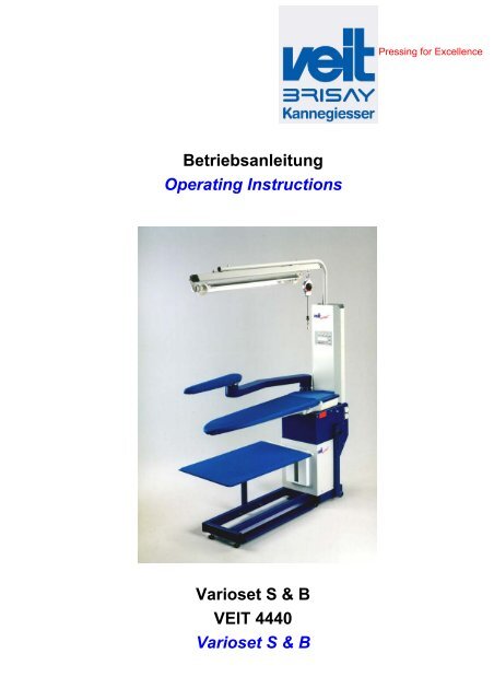
<strong>Betriebsanleitung</strong><br />
<strong>Operating</strong> <strong>Instructions</strong><br />
<strong>Varioset</strong> S & B<br />
<strong>VEIT</strong> <strong>4440</strong><br />
<strong>Varioset</strong> S & B<br />
Pressing for Excellence
Service Hotline<br />
<strong>VEIT</strong> GmbH<br />
Justus-von-Liebig-Str. 15<br />
D - 86899 Landsberg am Lech<br />
Germany<br />
Phone +49 (81 91) 479 0<br />
Fax +49 (81 91) 479 149<br />
www.veit-group.com<br />
Germany: +49 (81 91) 479 133<br />
Europe: +49 (81 91) 479 252<br />
America: +1 (770) 868 8060<br />
Asia: +852 2111 9795<br />
Ersatzteile/Spare parts<br />
Vertrieb/Sales +49 (8191) 479 176<br />
Vertrieb Textilpflege/ +49 (8191) 479 129<br />
Sales Textile care
Inhaltsverzeichnis / Table of Contents:<br />
<strong>Varioset</strong> S & B<br />
<strong>VEIT</strong> <strong>4440</strong><br />
1 Übersichtsdarstellung / Survey Drawing 4<br />
2 Warnhinweise / Warnings 5<br />
3 Technische Daten CR2 / Technical Data CR2 6<br />
4 Technische Daten CR3 / Technical Data CR3 8<br />
5 Technische Daten CR4 / Technical Data CR4 10<br />
6 Allgemeine Informationen / General Information 12<br />
6.1 Gerät aufbauen / Assembly 12<br />
6.2 Elektrischer Anschluss / Power Supply 12<br />
6.3 Einschalten / Ausschalten / On / Off 12<br />
6.4 Transport / Transportation 12<br />
6.5 Höhenverstellung / Height Adjustment 12<br />
7 Betrieb / Operation 13<br />
7.1 Programmieranleitung / Programming <strong>Instructions</strong> 13<br />
7.1.1 Bedienungsfeld / <strong>Operating</strong> Panel 13<br />
7.2 Technische Beschreibung / Technical Specification 22<br />
8 Wartung und Pflege / Maintenance and Service 23<br />
9 Störungen und ihre Beseitigung / Malfunctions and<br />
Troubleshooting 24<br />
10 Aufbauanleitung / Assembly <strong>Instructions</strong> 27<br />
10.1 DOB-Bügelplatz Spitze links / Dress Board Ironing Tables Point Left 28<br />
10.2 Universal – Bügelplatz Spitze rechts / Universal Ironing Tables Point Right 29<br />
10.3 Universal – Bügelplätze / Universal Ironing Tables 30<br />
10.4 Flächen – Bügelplätze / Flat Top Ironing Tables 30<br />
10.5 Spezial – Bügelplätze / Special Ironing Tables 31<br />
10.6 Abwindkamin und Gitteraufsatz / Air-Vent-Chimney and Air-Vent-Grill 31<br />
10.7 Schutz für Kamin und Schwenkarm / Protection for Chimney and Swivel Arm 32<br />
10.8 Stützlager / Swivelarm Bracket 32<br />
11 Ersatzteile / Spare Parts 35<br />
11.1 Zeichnung / Drawing 35<br />
11.2 Ersatzteilliste / Spare Parts List 36<br />
12 Schaltpläne / Circuit Diagrams 38<br />
12.1 Schützplatine / Contactor – Board 380-415V, 50/60Hz 38<br />
12.2 Schützplatine / Contactor – Board 3x200-220V, 50/60Hz 39<br />
12.3 Schützplatine / Contactor – Board 1x200-220V, 50/60Hz 40<br />
12.4 Steuerungsplatine / Controlling PC-Board 3x200-220V, 380-415V, 50/60Hz 41<br />
12.5 Konfiguration der Steuerungsplatine / Voltage Adjustment of the Controlling<br />
PC-Board 42<br />
12.6 Veitronic Platine / Veitronic PC-Board 3x200-220V, 380-415V, 50/60Hz 43<br />
12.7 Hochdruckbügler / High Pressure Iron 3x200-220V, 380-415V, 50/60Hz 44<br />
13 Merkblatt <strong>4440</strong>-004 / Information Leaflet <strong>4440</strong>-004 45<br />
14 Merkblatt <strong>4440</strong>-005 / Information Leaflet <strong>4440</strong>-005 45<br />
15 EG-Konformitätserklärung / EC Declaration of<br />
Conformity 49<br />
11.07.2005 3
1 Übersichtsdarstellung / Survey Drawing<br />
Standfuss mit Fußschaltleiste<br />
- horizontale Fußschaltleiste für Saugen<br />
- vertikale Fußschaltleiste für Blasen<br />
Gummifuß verstellbar<br />
Adjustable rubber foot<br />
Fangtuchrahmen<br />
Spilltray frame with cloth<br />
Bügelfläche DOB<br />
Ironing surface dress board<br />
Schwenkarmanlage bestehend aus:<br />
- Schwenkarm<br />
- Bügelform<br />
- Stützlager mit Mikroschalter<br />
swivel arm, including:<br />
- swivel arm<br />
- ironing form<br />
- swivel arm bracket with microswitch<br />
Büglerschwebe mit:<br />
- Laufschiene<br />
- Rollen mit Balancer für Bügler<br />
- Arbeitsplatzbeleuchtung<br />
Iron gantry, including:<br />
- guide rail<br />
- balancer for iron<br />
- workplace lighting<br />
Zentralsteuerung mit Display<br />
Control unit with display<br />
Abwindkamin<br />
Air vent chimney<br />
<strong>Varioset</strong> S & B<br />
<strong>VEIT</strong> <strong>4440</strong><br />
Elektro-Box mit:<br />
electronic box, including:<br />
- Gerätehauptschalter<br />
- main switch<br />
- Steuerungsplatine<br />
- PC-board<br />
- Veitronic 2000 Büglerplatine - Veitronic 2000 board<br />
- Schützplatine für Gebläsemotor - contactor board for fan motor<br />
- Sicherungen<br />
- fuses<br />
- Steckdosen und Anschlußkabel - sockets and power cable<br />
Höhenverstellung mit:<br />
- Kreuzgriffschrauben (beidseitig)<br />
- gas pressure spring<br />
height adjustment, including:<br />
- both side star grip<br />
- gas pressure spring<br />
Transportrollen<br />
Transportation wheels<br />
Support Stand with kickerplate<br />
- horizontal kickerplate for suction<br />
- vertical kickerplate for blowing<br />
11.07.2005 4
2 Warnhinweise / Warnings<br />
1. Bügeltisch nur in vollständig montiertem Zustand in<br />
Betrieb nehmen!<br />
(Standfuß, Bügelfläche, je nach Ausstattung<br />
Abwindkamin, Gitteraufsatz)<br />
2. Das Gerät darf nur mit der Spannung und Stromart<br />
betrieben werden, die auf dem Typenschild angegeben<br />
sind.<br />
3. Störungen an der elektrischen Einrichtung dürfen nur<br />
durch zugelassene Fachkräfte behoben werden.<br />
4. Vor Öffnen des Gerätes Netzstecker ziehen und<br />
Verbindungskabel zum Dampferzeuger oder Kondensor<br />
trennen.<br />
5. Der Netzanschluss muss bauseitig abgesichert sein!<br />
6. Das Gerät ist mit Stecker ausgestattet. Der Stecker muss<br />
frei zugänglich sein und darf nicht verbaut werden. Ein<br />
Direktanschluss ohne Stecker ist nicht zulässig.<br />
7. Vorschriften örtlicher Elektrizitätsgesellschaften sind zu<br />
beachten.<br />
8. Es dürfen nur von Veit zugelassene Ersatz- und<br />
Zubehörteile verwendet werden.<br />
9. Der Bügeltisch dient ausschließlich dem Bügeln mit und<br />
ohne Dampf. Insbesondere ist die Fleckentfernung mit<br />
Lösungsmitteln oder anderen brennbaren oder<br />
explosiven Stoffen nicht zulässig.<br />
10. Beim Verschieben des Tisches oder bei<br />
Höhenverstellung darauf achten, dass das<br />
Anschlusskabel nicht eingeklemmt oder beschädigt<br />
wird.<br />
<strong>Varioset</strong> S & B<br />
<strong>VEIT</strong> <strong>4440</strong><br />
1. The ironing table should only be operated when it is<br />
completely assembled<br />
(support stand, ironing surface depending on<br />
equipment, air-vent-chimney, air-vent-grill, sound<br />
damper).<br />
2. Only use the voltage and type of current shown on the<br />
machine plate.<br />
3. Electrical faults must only be repaired by authorized<br />
personnel.<br />
4. Disconnect the power supply and the connection cable<br />
to the steam generator or condenser before opening the<br />
machine.<br />
5. The mains supply must be secured by the customer.<br />
6. The unit is supplied with a plug. Do not connect without<br />
a plug.<br />
7. Take note of the regulations of the local electric<br />
suppliers.<br />
8. Use only Veit spare parts and accessories.<br />
9. Do not use the ironing table for chemical spot removing.<br />
10. Take care not to damage the connection cable when<br />
moving the table or adjusting the height.<br />
11.07.2005 5
3 Technische Daten CR2 / Technical Data CR2<br />
<strong>Varioset</strong> S & B<br />
<strong>VEIT</strong> <strong>4440</strong><br />
11.07.2005 6
Elektrischer Anschluss:<br />
V 400<br />
Hz 50<br />
kW 0,55<br />
A 1,8<br />
Netzseitige Absicherung 16 A<br />
Anschlusskabel Länge: 4 m mit CEE-Stecker<br />
Luftmenge max. 1000 m3/h<br />
Gewicht 115 kg<br />
Bügelfläche 500 x 1388 mm<br />
Schalldruckpegel (1,6 m Höhe; 0,5 m Abstand von<br />
DOB CR 2: Saugen = 75 dB (A), Blasen = 75 dB (A)<br />
Vorderkante)<br />
DOB schmal: Saugen = 69 dB (A), Blasen = 73 dB (A)<br />
<strong>Varioset</strong> S & B<br />
<strong>VEIT</strong> <strong>4440</strong><br />
Electrical connection<br />
V 400<br />
Hz 50<br />
kW 0,55<br />
A 1,8<br />
Fuse protection 16 A<br />
Connection cable Length: 4 m with CEE plug<br />
Exhaust air volume max. 1000 m3/h<br />
weight 115 kg<br />
Ironing buck 500 x 1388 mm<br />
Sound pressure level (height 1.6 m; distance 0.5 m from the DOB CR2: Suction = 75 dB (A), Blowing = 75 dB (A)<br />
front of the unit)<br />
DOB narrow: Suction = 69 dB (A), Blowing = 73 dB (A)<br />
11.07.2005 7
4 Technische Daten CR3 / Technical Data CR3<br />
<strong>Varioset</strong> S & B<br />
<strong>VEIT</strong> <strong>4440</strong><br />
11.07.2005 8
Elektrischer Anschluss:<br />
V 400<br />
Hz 50<br />
kW 0,55<br />
A 1,8<br />
Netzseitige Absicherung 16 A<br />
Anschlusskabel Länge: 4 m mit CEE-Stecker<br />
Luftmenge max. 1000 m3/h<br />
Gewicht 115 kg<br />
Bügelfläche 1300 x 650 mm<br />
Schalldruckpegel (1,6 m Höhe; 0,5 m Abstand von<br />
DOB CR 2: Saugen = 75 dB (A), Blasen = 75 dB (A)<br />
Vorderkante)<br />
DOB schmal: Saugen = 69 dB (A), Blasen = 73 dB (A)<br />
<strong>Varioset</strong> S & B<br />
<strong>VEIT</strong> <strong>4440</strong><br />
Electrical connection<br />
V 400<br />
Hz 50<br />
A 1,8<br />
kW 0,55<br />
Fuse protection 16 A<br />
Connection cable Length: 4 m with CEE plug<br />
Exhaust air volume max. 1000 m3/h<br />
weight 115 kg<br />
Ironing buck 1300 x 650 mm<br />
Sound pressure level (height 1.6 m; distance 0.5 m from the DOB CR2: Suction = 75 dB (A), Blowing = 75 dB (A)<br />
front of the unit)<br />
DOB narrow: Suction = 69 dB (A), Blowing = 73 dB (A)<br />
11.07.2005 9
5 Technische Daten CR4 / Technical Data CR4<br />
<strong>Varioset</strong> S & B<br />
<strong>VEIT</strong> <strong>4440</strong><br />
11.07.2005 10
Elektrischer Anschluss<br />
V 400<br />
Hz 50<br />
kW 0,55<br />
A 1,8<br />
Netzseitige Absicherung 16 A<br />
Anschlusskabel Länge: 4 m mit CEE-Stecker<br />
Luftmenge max. 1000 m3/h<br />
Gewicht 115 kg<br />
Schalldruckpegel (1,6 m Höhe; 0,5 m Abstand von<br />
DOB CR 2: Saugen = 75 dB (A), Blasen = 75 dB (A)<br />
Vorderkante)<br />
DOB schmal: Saugen = 69 dB (A), Blasen = 73 dB (A)<br />
<strong>Varioset</strong> S & B<br />
<strong>VEIT</strong> <strong>4440</strong><br />
Electrical connection<br />
V 400<br />
Hz 50<br />
kW 0,55<br />
A 1,8<br />
Fuse protection 16 A<br />
Connection cable Length: 4 m with CEE plug<br />
Exhaust air volume max. 1000 m3/h<br />
weight 115 kg<br />
Sound pressure level (height 1.6 m; distance 0.5 m from the DOB CR2: Suction = 75 dB (A), Blowing = 75 dB (A)<br />
front of the unit)<br />
DOB narrow: Suction = 69 dB (A), Blowing = 73 dB (A)<br />
11.07.2005 11
6 Allgemeine Informationen / General Information<br />
6.1 Gerät aufbauen / Assembly<br />
Für den Aufbau der verschiedenen Geräte und<br />
Zusatzeinrichtungen stehen je nach Bedarf entsprechende<br />
Aufbau-Anleitungen zur Verfügung. (Entnehmen Sie diese bitte<br />
den Einzel-Aufbauanleitungen in Abschnitt 8).<br />
6.2 Elektrischer Anschluss / Power Supply<br />
Das Gerät ist mit einem entsprechenden Stecker ausgestattet;<br />
Kabellänge 4 m. In diesem Bereich ist eine Anschlussmöglichkeit<br />
zu schaffen.<br />
Direktanschluss ohne Stecker ist nicht zulässig!<br />
Achtung!<br />
Der Motor ist polumschaltbar. Sollte der Motor entgegen der<br />
Drehrichtung laufen, sind die Phasen L1 und L3 zu vertauschen.<br />
6.3 Einschalten / Ausschalten / On / Off<br />
<strong>Varioset</strong> S & B<br />
<strong>VEIT</strong> <strong>4440</strong><br />
Please see special assembly instructions for base modules and<br />
additional units (section 8).<br />
The device is fitted with a suitable plug; length of cable 4 m.<br />
Direct supply without plug is not admitted!<br />
Caution!<br />
The motor is pole changing. If the motor is running in reverse,<br />
phase L1 and L3 have to be reversed.<br />
Mit dem Geräteschalter (Hauptschalter) hinten am Grundgerät. Main switch at the rear of the base unit.<br />
6.4 Transport / Transportation<br />
Das Gerät kann nach Ankippen auf die hinteren Transportrollen<br />
leicht bewegt werden. Für Flächen- und Universal-Bügelplätze<br />
kann der Transportwagen E 29 eingesetzt werden.<br />
6.5 Höhenverstellung / Height Adjustment<br />
Durch Lösen der beiden seitlichen Sterngriffe lässt sich das<br />
Gerät auf die gewünschte Höhe einstellen. Dabei darauf achten,<br />
dass das Anschlusskabel nicht gequetscht wird.<br />
Base module can easily be moved by transportation wheels.<br />
Transporting unit E 29 is used for flat top and touch-up ironing<br />
tables.<br />
Release the two star-grip bolts to adjust height. Take care that<br />
the connection cable could not be damaged.<br />
11.07.2005 12
7 Betrieb / Operation<br />
7.1 Programmieranleitung / Programming <strong>Instructions</strong><br />
7.1.1 Bedienungsfeld / <strong>Operating</strong> Panel<br />
Funktionstasten , , <br />
Function keys , , <br />
Der Text auf dem Display ist so aufgeteilt, dass jeder<br />
Funktionstaste , , das Schriftfeld zugeordnet ist,<br />
das unter der Funktionstaste liegt.<br />
Mit den Funktionstasten , , kann eine der<br />
Funktionen, die auf dem Display in der ersten Zeile angezeigt<br />
werden, angewählt und verändert werden.<br />
Mit der oder -Taste können angewählte Werte<br />
vergrößert oder verkleinert werden.<br />
Die Bedienoberfläche des <strong>Varioset</strong> S + B ist beim Standardmenü<br />
in 2 Bedienebenen aufgeteilt (im Auslieferungszustand).<br />
Durch Drücken der Menütaste kann von einer Ebene zur<br />
nächsten Ebene gesprungen werden.<br />
Das "Erweiterte Menü" teilt sich in 5 Bedienebenen auf.<br />
Mit folgenden Tasten können zwei Menüarten gewählt werden:<br />
Taste beim Einschalten drücken: Erweitertes Menü aktiv<br />
< -> Taste beim Einschalten drücken: Standard Menü aktiv<br />
Die Einstellung bleibt auch nach dem Ausschalten des<br />
Bügeltisches gespeichert.<br />
Grundbetriebsarten<br />
ACHTUNG!<br />
Bei einem Austausch der Steuerungsplatine muss eine<br />
Erstinitialisierung durchgeführt werden, siehe dazu<br />
Abschnitt 7.<br />
Menütaste <br />
Menu key <br />
Tasten , <br />
Keys , <br />
Zweizeiliges Display<br />
Two line display<br />
<strong>Varioset</strong> S & B<br />
<strong>VEIT</strong> <strong>4440</strong><br />
The text fields on the display are arranged so as to have the<br />
appropriate text appear beneath the appropriate function key, i.e.<br />
, , or .<br />
Using the , , function keys, one of the functions<br />
appearing in the first line of the corresponding display can be<br />
selected and modified.<br />
Using the or key, any parameter so selected can be<br />
increased or decreased.<br />
To branch from one menu level to the text one, actuate the <br />
key.<br />
The extended menu of your <strong>Varioset</strong> S+B features 5 levels.<br />
Using the following keys, two menus can be selected:<br />
Press key when switching on: Extended menu active<br />
Press key when switching on: Standard menu active<br />
The adjustment remains stored after the ironing table is switched<br />
off.<br />
Basic <strong>Operating</strong> Ways<br />
ATTENTION!<br />
When replacing the control pc-board, a first-initialization<br />
must be carried out, see section 7.<br />
11.07.2005 13
Der Bügeltisch kann mit verschiedenen Bügeleisen (Erkennung<br />
erfolgt automatisch vom Bügeltisch) betrieben werden:<br />
- <strong>VEIT</strong>-Bügeleisen HD 2002 - angeschlossen an E-Box<br />
von Bügeltisch<br />
- <strong>VEIT</strong>-Bügeleisen HD 2000 - angeschlossen an<br />
Veitronic<br />
- Bügeleisen eines anderen Herstellers<br />
Das <strong>VEIT</strong>-Bügeleisen HD 2002 wird über sein Adapterkabel an<br />
den Bügeltisch angeschlossen und vom Bügeltisch automatisch<br />
erkannt.<br />
Ist ein <strong>VEIT</strong>-Bügeleisen HD 2002 (Standard für diesen Tisch)<br />
nicht angeschlossen, werden am Display folgende Funktionen<br />
nicht mehr angezeigt:<br />
- Temperaturistwert des Büglers<br />
- Temperatursollwert des Büglers<br />
<strong>Varioset</strong> S & B<br />
<strong>VEIT</strong> <strong>4440</strong><br />
The ironing table can be operated with different irons (automatic<br />
recognition):<br />
- <strong>VEIT</strong> HD 2002 iron – connected to E-box of the ironing<br />
table<br />
- <strong>VEIT</strong> HD 2000 iron – connected to the Veitronic<br />
- Iron of another supplier<br />
The <strong>VEIT</strong> HD 2002 iron is connected via the adapter cable to the<br />
ironing table and is recognized automatically by the ironing table.<br />
If a <strong>VEIT</strong> HD 2002 iron (standard iron for this table) is not<br />
connected, the following functions are no longer displayed:<br />
- actual temperature of the iron<br />
- set point temperature value of the iron<br />
Für Ausnahmefälle: For exceptions:<br />
Abschalten der automatischen Erkennung: Switch off the automatic recognition:<br />
- und die Taste beim Einschalten gleichzeitig drücken. Press simultaneously the key and the key when<br />
Die Temperaturregelung und -anzeige durch den Bügeltisch ist switching on. The temperature control and indication by the<br />
abgeschaltet<br />
ironing table is switched off.<br />
Einschalten der automatischen Erkennung: Switch on the automatic recognition:<br />
- und die Taste beim Einschalten gleichzeitig drücken. Press simultaneously the key and key when switching<br />
on.<br />
Einstellungen<br />
Nach dem Einschalten des Bügeltisches erscheint auf dem<br />
Display die Wartungsintervallanzeige. Nach 5 Sekunden<br />
erfolgt automatisch die Umschaltung in die Betriebsebene<br />
(1) und der Bügeltisch ist betriebsbereit.<br />
Je nach gewähltem Menü (Standard bzw. Erweitertes Menü)<br />
bewegt man sich in 2 oder 5 Ebenen. Hier wird das<br />
"Erweiterte Menü" beschrieben.<br />
<strong>Operating</strong><br />
After switching on the ironing table the maintenance interval<br />
display appears on the display. After five seconds the<br />
branch to the operating level (1) is effected automatically<br />
and the ironing table is ready for operation.<br />
Depending on the menu selected (standard or extended<br />
menu) 2 or 5 levels are concerned. Here the „extended<br />
menu“ is described.<br />
Wartungsintervallanzeige<br />
Die zunehmende Anzahl der schwarzen Kästchen vor dem<br />
Wort „Service“ zeigen an, wie viel Zeit des eingestellten<br />
Wartungsintervalls seit dem letzten Reinigen der<br />
Gebläsespirale abgelaufen ist.<br />
Zur Einstellung des Wartungsintervalls siehe<br />
Zeiten/Sprachebene (5).<br />
Nach dem Ablauf des Wartungsintervalls erscheint an der<br />
Stelle der Wartungsintervallanzeige die<br />
Wartungsaufforderung.<br />
11.07.2005 14
Betriebsebene (1)<br />
<strong>Operating</strong> level (1)<br />
<strong>Varioset</strong> S & B<br />
<strong>VEIT</strong> <strong>4440</strong><br />
Maintenance interval display<br />
The amount of black boxes in front of the word „service“<br />
shows the time since the last cleaning of the fan spiral. For<br />
setting the maintenance interval refer to timer and<br />
language level (5).<br />
The next level will appear whenever the maintenance<br />
interval is over.<br />
Wartungsaufforderung<br />
Reinigen Sie die Gebläsespirale entsprechend den<br />
Anweisungen in Abschnitt 5 und bestätigen Sie die<br />
durchgeführte Wartung durch Drücken der - Taste.<br />
Die abgelaufene Wartungsintervallzeit wird auf 0 gesetzt<br />
und beim Einschalten erscheint wieder die<br />
Wartungsintervallanzeige.<br />
Wird die - Taste nicht gedrückt, dann erscheint bei<br />
jedem erneuten Einschalten des Bügeltisches die<br />
Wartungsaufforderung.<br />
Request for maintenance<br />
Clean the fan spiral according to instructions in chapter 6<br />
and confirm this by actuating . This assumes that the<br />
fan spiral was cleaned; the screen will be branched to the<br />
level mentioned above.<br />
If is not actuated, the request for maintenance<br />
appears at any switching on of the ironing table.<br />
In der Betriebsebene erfolgt die Einstellung der<br />
Betriebsparameter:<br />
1. Luftmenge für Saugen<br />
2. Luftmenge für Blasen<br />
3. Bügeleisentemperatur<br />
In the operating level the operating parameters are<br />
adjusted:<br />
1. air volume for suction<br />
2. air volume for blowing<br />
3. iron-temperature<br />
11.07.2005 15
Durch Drücken der Taste wechseln Sie in die nächste Ebene.<br />
Actuate : -> branch to next level<br />
Timerebene (2)<br />
Timer level (2)<br />
<strong>Varioset</strong> S & B<br />
<strong>VEIT</strong> <strong>4440</strong><br />
1. Einstellung des Luftmengen - Sollwerts für Saugen in %:<br />
drücken -> Anzeige ‘SAUG’ blinkt:<br />
mit der und Taste kann die Luftmenge zwischen<br />
0% und 100 % in Schritten von 10 % eingestellt werden.<br />
2. Einstellung des Luftmengen Sollwerts für Blasen in %:<br />
drücken -> Anzeige ‘BLAS’ blinkt:<br />
mit der und Taste kann die Luftmenge zwischen<br />
0% und 100 % in Schritten von 10 % eingestellt werden.<br />
3. Einstellung des Temperatur-Sollwerts an der Bügeleisensohle<br />
in °C:<br />
drücken -> Anzeige ‘TS’ blinkt:<br />
mit der und Taste kann der Temperatur - Sollwert<br />
zwischen 90°C und 230 °C in Schritten von 5°C eingestellt<br />
werden.<br />
Die Anzeige zeigt den Temperatur - Istwert an der<br />
Bügeleisensohle an. (gemessen in frei konvektierender Luft<br />
bei 20 °C)<br />
1. Air-volume suction set point (in %)<br />
Actuate : -> "SUCT" flashing:<br />
Using the and keys, air volumes can be readjusted<br />
in steps of 10% each between 0% and 100%.<br />
2. Air-volume blowing set point (in %)<br />
Actuate : -> "BLOW" flashing<br />
Using the and keys, air volumes can be readjusted<br />
in steps of 10% each between 0% and 100%.<br />
3. Iron-temperature set point value (in °C)<br />
Actuate : -> "TN" flashing:<br />
Using the and keys, the set point for the iron<br />
temperature can be adjusted, in steps of 5°C each, within a<br />
range from 90°C to 230°C.<br />
"TA": Actual iron temperature (in °C)<br />
Measured at the soleplate given freely circulating air (at<br />
20°C)<br />
Im Timer - Betrieb wird das Gebläse in Abhängigkeit des<br />
Dämpftasters am Bügeleisen eingeschaltet. Es können 4<br />
Betriebsarten eingestellt werden.<br />
In the timer level the fan is switched on depending on the<br />
steaming key of the iron. Four operating ways can be<br />
adjusted.<br />
1. TIMER AUS:<br />
Drücken Sie die Taste so lange mehrmals<br />
hintereinander bis das nebenstehende Display erscheint.<br />
Es wird kein Timerprogramm aktiviert, d.h. manueller<br />
Betrieb mit Fußschaltleiste.<br />
Durch Drücken der Taste wechseln Sie in die nächste<br />
Betriebsart<br />
11.07.2005 16
1. Timer off:<br />
Actuate as long as the display beside appears.<br />
<strong>Varioset</strong> S & B<br />
<strong>VEIT</strong> <strong>4440</strong><br />
No timer is activated, that means manual operating with<br />
kicker plate.<br />
Actuate : -> branch to next<br />
timer level<br />
2. PROG 1:<br />
Das Gebläse schaltet sich nach einer einstellbaren<br />
Verzögerungszeit nach dem Betätigen des Dämpftasters<br />
ein. Nach dem Loslassen des Dämpftasters läuft das<br />
Gebläse weiter bis die eingestellte Nachsaugzeit<br />
abgelaufen ist.<br />
Einstellen der Verzögerungszeit:<br />
F2> drücken -> Anzeige ‘VERZ’ blinkt:<br />
mit der und Taste kann die Verzögerungszeit<br />
zwischen 0 s und 20 s in Schritten von 1 s eingestellt<br />
werden.<br />
Einstellen der Nachsaugzeit:<br />
F3> drücken -> Anzeige ‘SAUG’ blinkt:<br />
mit der und Taste kann die Nachsaugzeit zwischen<br />
0 s und 20 s in Schritten von 1 s eingestellt werden.<br />
Durch Drücken der Taste wechseln Sie in die nächste<br />
Betriebsart<br />
2. PROG 1:<br />
As soon as the steaming key on the iron is pushed, the<br />
delay time will be started. Once it is over, the fan will be<br />
switched on. After the steaming key has been released, the<br />
fan will keep running until the additional suction time is over.<br />
Delay time set point:<br />
Actuate : -> "DELAY" flashing:<br />
Using the and keys, times can be set in steps of 1<br />
s each, within a range from 0 s to 20 s.<br />
Suction time set point:<br />
Actuate : -> "SUCT" flashing:<br />
Using the and keys, times can be set in steps of 1<br />
s each, within a range from 0 s to 20 s.<br />
Actuate : -> branch to next timer level.<br />
11.07.2005 17
<strong>Varioset</strong> S & B<br />
<strong>VEIT</strong> <strong>4440</strong><br />
3. PROG 2:<br />
Nachdem der Dämpftaster am Bügeleisen gedrückt und<br />
wieder losgelassen wurde wird nach der einstellbaren<br />
Pausenzeit das Gebläse eingeschaltet und läuft für die<br />
Dauer der eingestellten Nachsaugzeit.<br />
Einstellen der Pausenzeit:<br />
F2> drücken -> Anzeige ‘PAUSE’ blinkt:<br />
mit der und Taste kann die Pausenzeit zwischen 0<br />
s und 20 s in Schritten von 1 s eingestellt werden.<br />
Einstellen der Nachsaugzeit:<br />
F3> drücken -> Anzeige ‘SAUG’ blinkt:<br />
mit der und Taste kann die Nachsaugzeit zwischen<br />
0 s und 20 s in Schritten von 1 s eingestellt werden.<br />
Durch Drücken der Taste wechseln Sie in die<br />
nächste Betriebsart<br />
3. PROG 2:<br />
As soon as the steaming key on the iron is pushed and<br />
released again, the "INTER" time will be started. Once this<br />
interval time has lapsed, the fan will be switched on. The<br />
fan will keep running as per the additional suction time<br />
preset<br />
Interval time set point:<br />
Actuate : -> "INTER" flashing:<br />
Using the and keys, times can be set in steps of 1<br />
s each, within a range from 0 s to 20 s.<br />
Suction time set point:<br />
Actuate : -> "SUCT" flashing:<br />
Using the and keys, times can be set in steps of 1<br />
s each, within a range from 0 s to 20 s.<br />
Actuate : -> branch to next timer level<br />
4. TEACH:<br />
Diese Timerprogramm ermöglicht die Abarbeitung eines<br />
individuellen Bügelprogramms auf der Basis eines<br />
Beispielbügelvorgangs.<br />
Zur Aufnahme der individuellen Zeiten wechseln Sie durch<br />
Drücken der Taste in die Aufnahmeebene T - PRG.<br />
Arbeiten Sie einen kompletten Bügelvorgang mit Drücken<br />
des Dampftasters und der Fußschaltleiste ab. Die<br />
entsprechende Verzögerungs- oder Pausenzeit und die<br />
Nachsaugzeit werden erfasst und im Programm TEACH<br />
abgelegt. Der Rücksprung in diese Programmebene erfolgt<br />
automatisch. Sie können die abgespeicherten Zeiten<br />
jedoch auch verändern. Gehen Sie hierbei vor wie unter<br />
PROG 1 und PROG 2 beschrieben.<br />
11.07.2005 18
Durch drücken der Taste wechseln Sie in die nächste Ebene.<br />
Actuate : -> branch to next level<br />
Stückzahlebene (3)<br />
Piece number level (3)<br />
<strong>Varioset</strong> S & B<br />
<strong>VEIT</strong> <strong>4440</strong><br />
4. TEACH:<br />
Depending upon whether ironing was performed on T-Prog<br />
level, a program comprising a "DELAY" time or an "INTER"<br />
time will be stored under TEACH for processing whenever<br />
ironing is to be performed.<br />
To store an individual program branch to the T-Prog level<br />
by actuating . Now perform a complete ironing<br />
process including pushing the steaming key and the kicker<br />
plate.<br />
The corresponding "DELAY" or "INTER" and "SUCT“ time<br />
settings will be stored in program „TEACH“ and are<br />
available by choosing this program level (4).<br />
For changing the time settings proceed like it is referred<br />
under PROG1 or PROG2.<br />
In dieser Ebene können Stückzahlen von 3 verschiedenen<br />
Bügelwaren gezählt werden. T_1, T_2 und T_3 stehen für<br />
Stückzahlen.<br />
Durch Drücken einer der Funktionstasten , oder<br />
wird die zugehörige Stückzahl um 1 erhöht.<br />
Wenn vor der entsprechenden Funktionstaste die <br />
Taste gedrückt wird, erniedrigt sich die zugehörige<br />
Stückzahl um 1.<br />
Um einen Stückzahlwert auf Null zu setzen drücken Sie die<br />
zugehörige Funktionstaste , oder länger<br />
als 2sek.<br />
On this level, the number of pieces to be ironed can be<br />
input for three different products. P-1, P-2 and P-3<br />
correspond to piece numbers.<br />
By actuating one of the , or function keys,<br />
the corresponding piece number will be increased by 1. If a<br />
piece number is to be decreased by 1, the will have to<br />
be pushed before the corresponding function key is<br />
actuated. If any piece number is to be reset to zero, keep<br />
pushing the corresponding function key , or<br />
for more than 2 s.<br />
Durch Drücken der Taste wechseln Sie in die nächste Ebene.<br />
Actuate : -> branch to next level<br />
Saug/Blas - Optionsebene (4)<br />
In dieser Ebene können einige Grundeinstellungen<br />
vorgenommen werden.<br />
Suction/blowing – option level (4)<br />
In this level some basic adjustments can be made.<br />
11.07.2005 19
1. FUSS<br />
Legt die Startstellung der Klappen fest<br />
S / B: Die Klappen befinden sich ohne Betätigung der<br />
Fußschaltleiste in Saugposition<br />
• waagerechter Fußschalter: Saugen<br />
• senkrechter Fußschalter : Blasen<br />
B / S: Die Klappen befinden sich ohne Betätigung der<br />
Fußschaltleiste in Blasposition<br />
• waagerechter Fußschalter: Blasen<br />
<strong>Varioset</strong> S & B<br />
<strong>VEIT</strong> <strong>4440</strong><br />
• senkrechter Fußschalter: Saugen<br />
Die Umschaltung erfolgt durch Drücken der Taste <br />
2. A - S / B<br />
Automatisches Saugen oder Blasen<br />
Es darf kein Timerprogramm aktiviert und unter A - S / B<br />
muss ‘ja’ eingestellt sein. Wird beim Loslassen des<br />
Dämpftasters die Fußschaltleiste betätigt, so läuft das<br />
Gebläse 2 Sek. lang nach. (Die Fußschaltleiste kann<br />
losgelassen werden.)<br />
Durch Drücken von der Taste wird diese Betriebsart<br />
abgeschlossen.<br />
3. S - S / B<br />
Beschleunigung der Blasbereitschaft des Bügeltisches<br />
Bei der Einstellung ‘JA’ fährt die Saug / Blas - Klappe bei<br />
Betätigung des Blas - Fußschalters sofort in die Blas -<br />
Position. Die Blas - Luftmenge wird erst danach geregelt.<br />
Die Umschaltung erfolgt durch Drücken der Taste <br />
1. Foot<br />
S/B: horizontal kicker plate: suction<br />
vertical kicker plate: blowing<br />
B/S: horizontal kicker plate: blowing<br />
vertical kicker plate: suction<br />
Actuate : -> switching from S/B to B/S or vice-versa<br />
2. A- S/B<br />
Automatic suction/blowing<br />
No timer program may be activated and „Yes“ must be set<br />
under A - S/B. If the kicker plate is actuated while the steam<br />
button is released, the fan is still running for 2 sec. (The kicker<br />
plate may be released).<br />
If the key is pressed, this mode of operation is finished.<br />
3. F- S / B<br />
Increasing the speed of change between suction and blowing.<br />
If „YES“ has been selected, the suction/ blowing flap<br />
immediately moves to blowing position after pressing the<br />
blowing kicker plate. The air volume will be set afterwards.<br />
Actuate : -> switching F-S/B from YES to NO and vice<br />
versa<br />
Durch Drücken der Taste wechseln Sie in die nächste Ebene.<br />
Actuate : -> branch next level.<br />
Zeiten und Sprachebene (5)<br />
In dieser Ebene können das Wartungsintervall und die<br />
Sprache der Bedienoberfläche eingestellt werden.<br />
Timer and language level (5)<br />
In this level maintenance interval and language of the<br />
operating panel can be adjusted.<br />
11.07.2005 20
Wenn in der Saug / Blas - Optionsebene oder in der Zeiten<br />
/ Sprach - Optionsebene 5 s lang keine Taste gedrückt<br />
wird, schaltet die Anzeige automatisch in die<br />
Betriebsebene (1) um. Durch Drücken der Taste<br />
erfolgt ebenfalls die Umschaltung in die Betriebsebene (1)<br />
<strong>Varioset</strong> S & B<br />
<strong>VEIT</strong> <strong>4440</strong><br />
1. B . St .<br />
Betriebsstundenanzeige für die Laufzeit des Gebläsemotors<br />
2. V I n t<br />
Einstellung der Gebläselaufzeit in Stunden, nach der eine<br />
Aufforderung zum Reinigen des Lüfterrades angezeigt wird.<br />
(Wartungsintervallanzeige beim Einschalten)<br />
F2> drücken -> Anzeige ‘V I n t’ blinkt:<br />
mit der und Taste kann die Gebläselaufzeit zwischen<br />
10 h und 250 h in Schritten von 5 h eingestellt werden.<br />
3. LANGU<br />
Einstellung der Sprache der Bedienoberfläche. Es stehen<br />
derzeit 5 Sprachen zur Verfügung.<br />
Die Umschaltung erfolgt durch Drücken der Taste <br />
1. Op. Hr<br />
Hours of operation for fan motor.<br />
2. SINT<br />
Hours between maintenance requests.<br />
Actuate : -> ‘SINT’ flashing<br />
Using the and keys, time can be set in steps of 5 h<br />
each between 10 h and 250 h.<br />
3. LANGU<br />
Adjustment of language in the operating panel. 5 languages<br />
are available<br />
Actuate : -> change language<br />
If no key is actuated for 5 s, the unit will branch back to<br />
the operation level 1. Actuate : -> branch operation<br />
level 1.<br />
11.07.2005 21
7.2 Technische Beschreibung / Technical Specification<br />
Steckverbindungen / Plug-in Connections<br />
1 Diodenstecker Fußschaltleiste an Elektrik-Box 1 diode plug kicker plate to electric box<br />
2 Steuerkabel/Abwindkamin an Elektrik-Box 2 control cable / air-vent chimney to electric box<br />
3 Stecker 4-pol./Elektrik-Box an Dampfgeber 3 4-core plug / electric box to steam supply<br />
4 Dampfschlauch/Bügler an Dampfgeber 4 steam hose / iron to steam supply<br />
5 Kabeldose 6-pol. /Elektrik-Box an Bügler 5 cable socket 6-core / electric box to iron<br />
6 Netzanschluss 6 mains supply<br />
<strong>Varioset</strong> S & B<br />
<strong>VEIT</strong> <strong>4440</strong><br />
11.07.2005 22
8 Wartung und Pflege / Maintenance and Service<br />
ca. alle 40 Betriebsstunden<br />
oder nach 4 Wochen<br />
ca. alle 40 Betriebsstunden<br />
oder nach 4 Wochen<br />
Bei Aufforderung in der<br />
Wartungsintervallanzeige oder<br />
ca. 1 x jährlich<br />
After approx. 40 working hours<br />
or after 4 weeks<br />
After approx. 40 working hours<br />
or after 4 weeks<br />
If shown on the maintenance<br />
interval display or approx.<br />
once a year<br />
Schaumstoff und Kunstfaserbezug waschen bei 30° in der Waschmaschine oder<br />
Handwäsche<br />
Prefittbezug und Silikonauflage überprüfen und<br />
gegebenenfalls reinigen<br />
<strong>Varioset</strong> S & B<br />
<strong>VEIT</strong> <strong>4440</strong><br />
mit einer harten Bürste abbürsten und mit<br />
Pressluft ausblasen<br />
Gebläselüfterrad reinigen je nach Verschmutzung, Lamellen mit<br />
Pinsel oder Pressluft reinigen. Zum<br />
Lüfterrad-Ausbau siehe<br />
Ersatzteilzeichnung<br />
Clean the foam layer and the synthetic cover In the washing machine at 30°C or with<br />
warm water by hand<br />
Check the Prefitt cover and the silicon-layer.<br />
Clean them, if necessary<br />
Use a hard brush and compressed air<br />
Clean the impeller Clean the blades with a brush or<br />
compressed air depending on soiling. For<br />
removing the impeller, please see spare<br />
part drawing<br />
Wartungsanweisung<br />
Gebläselüfterrad reinigen<br />
Achtung !<br />
Netzstecker ziehen<br />
Seitliche Blechschrauben lösen und Elektrik -<br />
Box nach unten ausschwenken.<br />
Lüfterrad mit Pinsel, Pressluft oder<br />
Staubsauger reinigen.<br />
Maintenance instructions<br />
Cleaning of the impeller<br />
Caution!<br />
Disconnect power supply<br />
Remove screws at the side and swing down<br />
the E-Box.<br />
Clean the blades with a brush, compressed air<br />
or a vacuum cleaner.<br />
11.07.2005 23
9 Störungen und ihre Beseitigung / Malfunctions and Troubleshooting<br />
Versuchen Sie nach dem Auftreten einer Störfallanzeige<br />
zuerst, durch Betätigen der -Taste das Steuerprogramm<br />
erneut zu starten. Erscheint die gleiche Fehlermeldung<br />
erneut, so handelt es sich um einen Defekt der von<br />
fachkundigem Personal behoben werden muss!<br />
7.1 Schlechte Absaugung bzw.<br />
Blaswirkung<br />
<strong>Varioset</strong> S & B<br />
<strong>VEIT</strong> <strong>4440</strong><br />
In case of a trouble indication (error message on display)<br />
first try to confirm the message by pressing . The<br />
program should start up again. If the error still displayed, a<br />
serious defect has occurred and should be eliminated by<br />
authorized specialists.<br />
Störung Ursache Abhilfe<br />
Gebläse läuft in falscher<br />
Richtung<br />
Gerätestecker (Pos. 06) öffnen, Phasen L1 und<br />
L3 vertauschen<br />
7.2 Keine Absaugung bzw. Blaswirkung Gebläsemotor läuft nicht 1. Thermoschutz im Motor hat durch Überlastung<br />
(Überhitzung) ausgeschaltet; nach Abkühlung (ca.<br />
15 Minuten) wieder betriebsbereit<br />
2. Fußschalter überprüfen (Pos. 36)<br />
3. Elektrik-Box lösen, Schütz auf Platine prüfen<br />
(Pos. 02)<br />
7.3 Gebläsemotor läuft nicht Lüfterrad verschmutzt und<br />
daher Unwucht<br />
7.4 Beim Einschwenken des<br />
Schwenkarmes bleibt die Absaugung<br />
bzw. Blaswirkung auf die Bügelfläche<br />
bestehen<br />
7.5 Beim Wegschwenken setzt Absaugung<br />
bzw. Blaswirkung auf Fläche nicht ein<br />
7.6 Keine Absaugung auf Bügelfläche bzw.<br />
Schwenkarm<br />
7.7<br />
Anzeige am Display verschwindet nicht<br />
Lüfterrad reinigen (Pos. 08)<br />
(Zum Austausch siehe Kapitel 6 Wartung und<br />
Pflege)<br />
Klappe schließt nicht 1. Stellring am Schwenkarm ist nicht in richtiger<br />
Position<br />
Mikroschalter (Pos. 17) muss in Arbeitsstellung<br />
des Schwenkarmes gedrückt sein<br />
Klappe öffnet nicht 1. Stellring am Schwenkarm ist nicht in richtiger<br />
Position<br />
Mikroschalter (Pos. 17) muss in Arbeitsstellung<br />
des Schwenkarmes gedrückt sein<br />
Keine Klappenumstellung<br />
durch Stellmotor<br />
Kurzschluss Stellmotor 12 V<br />
oder Motorkabel<br />
Fußschaltleiste hat<br />
Masseschluss<br />
Steuerungsplatine ist defekt<br />
1. Sicherungen prüfen<br />
2. Schalter an der Fuß-Schaltleiste prüfen<br />
(Pos. 36)<br />
1. Stellmotor 12 V (Pos. 12) und Motorkabel (Pos.<br />
25) überprüfen<br />
2. Diodenstecker und Kabel zur Fußschaltleiste<br />
auf Masseschluss überprüfen (Pos. 1<br />
Diodenstecker einstecken, wie in Kapitel 5.2<br />
Technische Beschreibung)<br />
3. Steuerungsplatine austauschen (Pos. 05)<br />
7.8 Störmeldung am Display Siehe Kapitel 7 Störungen und ihre Abhilfe bei Fehlernummern, linke Spalte<br />
7.8.1<br />
7.8.2<br />
7.8.3<br />
Fehler 1<br />
Bestätigen <br />
Vorher:<br />
“Überlast1!!!”<br />
Fehler 2<br />
Bestätigen <br />
Vorher:<br />
“Überlast2!!!”<br />
Fehler 3<br />
Bestätigen <br />
Vorher:<br />
“Motorkabel 1?”<br />
Kurzschluss Stellmotor 24 V<br />
oder im Motorkabel<br />
Platine ist defekt<br />
Kurzschluss Stellmotor 12 V<br />
oder im Motorkabel<br />
Spannung zu gering<br />
Platine ist defekt<br />
Stellmotor 24 V bekommt<br />
keinen Strom oder Hallsensor<br />
liefert kein Signal<br />
Feindosierungsklappe<br />
schwergängig oder verhakt<br />
Platine ist defekt<br />
1. Stellmotor 24 V (Pos. 11) und Motorkabel (Pos.<br />
25) überprüfen<br />
2. Steuerungsplatine (Pos. 05) austauschen<br />
1. Stellmotor 12 V (Pos. 12) und Motorkabel (Pos.<br />
25) überprüfen<br />
2. Spannungsversorgung überprüfen<br />
3. Steuerungsplatine (Pos. 05) austauschen<br />
1. Stellmotor 24 V (Pos. 11), Motorkabel, Stecker<br />
und Klemme (Pos. 25) überprüfen<br />
2. Position der Klappe (Pos. 14) überprüfen und<br />
falls notwendig lösen<br />
3. Steuerungsplatine austauschen (Pos. 05)<br />
11.07.2005 24
7.8.4<br />
7.8.5<br />
7.8.6<br />
Fehler 4<br />
Bestätigen <br />
Vorher:<br />
“Motorkabel 2?”<br />
Fehler 5<br />
Bestätigen <br />
Vorher:<br />
“Motor 1 blockiert”<br />
Fehler 6<br />
Bestätigen <br />
Oder die tatsächliche Bügler-<br />
Temperatur ändert sich nicht oder bleibt<br />
bei einem bestimmten Wert stehen,<br />
obwohl die Temperatureinstellung<br />
geändert wird<br />
Vorher:<br />
“Bügler aus: Fühler Fehler”<br />
MALFUNCTIONS<br />
Stellmotor 12 V bekommt<br />
keinen Strom oder ist defekt<br />
Platine ist defekt<br />
Feindosierungsklappe ist<br />
blockiert, Hallsensor liefert<br />
kein Signal<br />
Kurzschluss Stellmotor 24 V<br />
oder im Motorkabel<br />
Platine ist defekt<br />
Temperaturfühler oder<br />
Anschlusskabel oder<br />
Veitronic-Platine oder<br />
Steuerungsplatine defekt<br />
7.1 Insufficient suction or blowing Impeller rotates the wrong<br />
way round<br />
<strong>Varioset</strong> S & B<br />
<strong>VEIT</strong> <strong>4440</strong><br />
1. Stellmotor 12 V (Pos. 12), Motorkabel, Stecker<br />
und Klemme (Pos. 25) überprüfen<br />
2. Steuerungsplatine austauschen (Pos. 05)<br />
1. Feindosierungsklappe (Pos. 14) im<br />
Klappenkasten auf Leichtgängigkeit überprüfen<br />
2. Stellmotor 24 V (Pos. 11) oder Motorkabel<br />
(Pos. 25) überprüfen<br />
3. Steuerungsplatine (Pos. 05) austauschen<br />
1. Temperaturfühler (im Bügeleisen) austauschen<br />
2. Anschlusskabel im Kabelbaum (Pos. 04)<br />
überprüfen<br />
3. Anschluss zwischen Veitronic und Platine (Pos.<br />
03) überprüfen<br />
4. Steuerungsplatine (Pos. 05) austauschen<br />
CAUSE TROUBLESHOOTING<br />
Open the unit plug (Pos. 06); invert phases L1<br />
and L3<br />
7.2 No suction or blowing Impeller motor does not run 1. Temperature protection in the motor switched<br />
off because of overheating; ready for operation<br />
after cooling down (approx. 15 min.)<br />
2. Test foot switch (Pos. 36)<br />
3. Remove electric box. Test contactor on the PCboard<br />
(Pos. 02)<br />
7.3 Fan motor does not work Impeller dirty and therefore<br />
out-of-balance<br />
7.4 Suction or blowing continues on the<br />
ironing surface, when swivelarm is<br />
turned in<br />
7.5 Suction or blowing on the ironing<br />
surface does not start, when the<br />
swivelarm is turned out<br />
7.6 No suction on ironing surface or on<br />
swivelarm<br />
Clean impeller (Pos. 08)<br />
(for replacing see chapter 6. Maintenance and<br />
Service)<br />
Flap does not close 1. The set collar at the swivelarm is not in correct<br />
position.<br />
2. Micro switch (Pos. 17) must be pushed, while<br />
swivel arm is in working position.<br />
Flap does not open 1. The set collar at the swivelarm is not in correct<br />
position.<br />
2. Micro switch (Pos. 17) must be pushed, while<br />
swivel arm is in working position.<br />
No flap reversing by<br />
servomotor<br />
1. Test fuse<br />
2. Test switch at the kicker plate (Pos. 36)<br />
11.07.2005 25
7.7<br />
Display doesn’t want disappear.<br />
Short circuit servomotor 12 V<br />
or its cables<br />
Kicker plate has earth contact<br />
PC Board defective<br />
<strong>Varioset</strong> S & B<br />
<strong>VEIT</strong> <strong>4440</strong><br />
1. Check servomotor 12 V (Pos. 12) and its<br />
cables (Pos. 25)<br />
2. Check diode plug and cable of kicker plate<br />
(Plug-in diode plug pos. 1, see chapter 5.2<br />
Technical Specification) have earth contact<br />
3. Replace PC Board control (Pos. 05)<br />
7.8 Error messages at the display See the cause and troubleshooting as per error number below<br />
7.8.1<br />
7.8.2<br />
7.8.3<br />
7.8.4<br />
7.8.5<br />
7.8.6<br />
Previous:<br />
“Overload1!!!”<br />
Previous:<br />
“Overload2!!!”<br />
Previous:<br />
“Motor cable 1?”<br />
Previous:<br />
“Motor cable 2?”<br />
Previous:<br />
“Motor 1 blocked”<br />
Or the actual iron temperature doesn’t<br />
change or fix at certain value while the<br />
temperature setting changed<br />
Previous:<br />
“Iron off: Sensor fault”<br />
Short circuit servomotor 24 V<br />
or its cables<br />
PC Board defective<br />
Short circuit servomotor 12 V<br />
or its cables<br />
Voltage too low<br />
PC Board defective<br />
Servomotor 24 V does not get<br />
any current or its hall sensor<br />
fails to provide signal<br />
Fine dosage flap does not<br />
move smoothly or it gets<br />
stuck<br />
PC Board defective<br />
Servomotor 12 V does not get<br />
any current or it is defective<br />
PC Board defective<br />
The flap is blocked. Hall<br />
sensor fails to provide signal<br />
Short circuit servomotor 24 V<br />
or its cables<br />
PC Board defective<br />
Temperature sensor or<br />
connection cable or<br />
Veitronic board or<br />
PC Board defective<br />
Wir empfehlen generell, vor dem Austausch von Platinen,<br />
alle Stecker und Stromversorgungen auf guten Kontakt zu<br />
überprüfen.<br />
1. Check servomotor 24 V (Pos. 11) and its<br />
cables (Pos. 25)<br />
2. Replace PC-board control (Pos. 05)<br />
1. Check servomotor 12 V (Pos. 12) and its<br />
cables (Pos. 25)<br />
2. Check Power supply<br />
3. Replace PC-board control (Pos. 05)<br />
1. Check servomotor 24 V (Pos. 11), cables,<br />
plugs and clamp (Pos. 25)<br />
2. Check the flap (Pos. 14), if necessary release<br />
the flap<br />
3. Replace PC-board control (Pos. 05)<br />
1. Check servomotor 12 V (Pos. 12) cables, plugs<br />
and clamp (Pos. 25)<br />
2. Replace PC-board control (Pos. 05)<br />
1. Check fine dosage flap (Pos. 14) within the<br />
register system for proper motion<br />
2. Check servomotor 24 V (Pos. 11) or its cables<br />
(Pos. 25)<br />
3. Replace PC-board control (Pos. 05)<br />
1. Replace temperature sensor (in the iron)<br />
2. Check connection cable in the wiring harness<br />
(Pos. 04)<br />
3. Check connection between Veitronic board and<br />
pc-board (Pos. 03)<br />
4. Replace PC-board control (Pos. 05)<br />
Generally, we recommend to check if all plugs and power<br />
supplies have good contact before exchanging the printed<br />
circuit boards.<br />
11.07.2005 26
ACHTUNG!<br />
Bei einem Austausch der Steuerungsplatine muss eine<br />
Erstinitialisierung wie folgt durchgeführt werden:<br />
Gerät ausschalten. Tasten und gleichzeitig<br />
drücken und dann Gerät einschalten.<br />
Eine ausführliche Anleitung zur Fehlerbehebung finden Sie auf<br />
unserer <strong>VEIT</strong> Service-CD, oder wenden Sie sich an Ihre<br />
zuständige Vertretung, bzw. unsere Service-Hotline.<br />
Die Service-Nummern lauten wie folgt:<br />
+ 49 (8191) 479 133 deutschsprachig<br />
+ 49 (8191) 479 252 englischsprachig<br />
10 Aufbauanleitung / Assembly <strong>Instructions</strong><br />
Bitte beachten Sie auch die mit den Ziffern<br />
gekennzeichneten Positionen in den folgenden<br />
Übersichtsdarstellungen.<br />
1 Grundgerät aufstellen. 1 Mount the base module.<br />
2 Stabilisierungsprofil aus dem Rechteckrohr des<br />
Grundrahmens ziehen. Kunststoffkappe auf der<br />
entsprechenden Seite des Standfußes abnehmen und mit<br />
dem Stabilisierungsprofil Grundrahmen und Standfuß<br />
verschrauben. Danach Standfuß mit Schrauben M 8x60<br />
am Grundgerät befestigen.<br />
<strong>Varioset</strong> S & B<br />
<strong>VEIT</strong> <strong>4440</strong><br />
ATTENTION!<br />
When replacing the control PC-board, a first initialization<br />
must be carried out as follows:<br />
Switch off the unit. Press the key and the key<br />
simultaneously and switch on the unit.<br />
On our <strong>VEIT</strong> Service-CD you can find a detailed instruction of<br />
how to get rid of defects or you can turn to your relevant<br />
representative respectively call our Service-Hotline.<br />
These are the Service Numbers:<br />
+ 49 (8191) – 479133 German Language<br />
+ 49 (8191) – 479252 English Language<br />
Please also note the positions marked with the numbers in<br />
the following figures.<br />
2 Pull the stabilizing profile out of the rectangular tube of the<br />
base frame. Remove the plastic cap on the corresponding<br />
side of the support stand and screw the base frame and<br />
the support stand on with the stabilizing profile. Then<br />
fasten the support stand by screws M 8x60 at the base<br />
module.<br />
3 Trägerplatte oben auf dem Grundgerät abschrauben. 3 Unscrew the supporting plate at the top of the base<br />
module.<br />
4 Mikroschalterkabel durch Langloch am Stützlager ziehen<br />
und dann das Stützlager am Grundgerät anschrauben<br />
(siehe auch 8.8).<br />
4 Pull the micro switch cable through the long hole at the<br />
swivel arm bracket and then fasten the swivel arm bracket<br />
at the base module with screws. (See 8.8).<br />
5 Mikroschalterkabel im Grundgerät anstecken. 5 Connect the micro switch cable to the base module.<br />
6 Kamin auf das Grundgerät montieren und Kabel der<br />
Display - Anzeige an den Stecker an der Unterseite der E<br />
- Box anschließen.<br />
6 Mount the chimney on the base module and connect the<br />
cable of the display to the plug at the bottom of the<br />
electronic box.<br />
7 Schwenkarmrohr montieren. 7 Assemble the swivelarm tube.<br />
8 Arbeitsplatzbeleuchtung montieren. 8 Mount the workplace illumination.<br />
9 Bügelfläche mit der Trägerplatte verschrauben, auf das 9 Fasten the ironing surface on the supporting plate with<br />
Grundgerät aufsetzen und Trägerplatte anschrauben.<br />
screws, put it on the base module and fasten the<br />
supporting plate with screws.<br />
10 Stützfuß am Standfuß anschrauben, Fangtuchrahmen 10 Screw the leg support on the support stand, put the<br />
und Fangtuch auflegen und mit den Flügelschrauben<br />
spilltray frame and the spilltray cloth on and clamp them by<br />
festklemmen.<br />
the wing screws.<br />
11 Bügeleisenabsteller montieren (nur bei Spitze rechts). 11 Mount the iron rest (at point right only).<br />
12 Fußschaltleiste in passende Position am Standfuß 12 Push the kicker plate in the suitable position at the support<br />
einstecken und das Kabel mit den selbstklebenden Clips stand and fix the cable by the self-adhesive clips. Connect<br />
befestigen. Kabelstecker an der Unterseite der E - Box<br />
the cable of the display to the plug at the bottom of the<br />
anschließen.<br />
electronic box.<br />
13 Bezug auf der Bügelfläche befestigen. 13 Fix the cover on the ironing surface.<br />
14 Bügelplatz am endgültigen Standort mit Hilfe der<br />
14 Adjust the ironing table at the final workplace to any<br />
höhenverstellbaren Gummifüße an Bodenunebenheiten unevenness of the floor by means of the height-adjustable<br />
anpassen und die Kontermuttern der Fußverstellung<br />
rubber feet and fasten the counter nuts of the foot<br />
anziehen.<br />
adjustment.<br />
15 Zur Höhenverstellung beide Sterngriffe am Grundgerät 15 Unscrew the two star grips at the base module to adjust<br />
lösen.<br />
the height.<br />
16 Schwenkarm mit Bügelform montieren. 16 Assemble the swivelarm with ironing buck.<br />
11.07.2005 27
10.1 DOB-Bügelplatz Spitze links / Dress Board Ironing Tables Point Left<br />
<strong>Varioset</strong> S & B<br />
<strong>VEIT</strong> <strong>4440</strong><br />
11.07.2005 28
10.2 Universal – Bügelplatz Spitze rechts / Universal Ironing Tables Point Right<br />
<strong>Varioset</strong> S & B<br />
<strong>VEIT</strong> <strong>4440</strong><br />
11.07.2005 29
10.3 Universal – Bügelplätze / Universal Ironing Tables<br />
10.4 Flächen – Bügelplätze / Flat Top Ironing Tables<br />
<strong>Varioset</strong> S & B<br />
<strong>VEIT</strong> <strong>4440</strong><br />
11.07.2005 30
10.5 Spezial – Bügelplätze / Special Ironing Tables<br />
10.6 Abwindkamin und Gitteraufsatz / Air-Vent-Chimney and Air-Vent-Grill<br />
Abwindkamin 900mm<br />
Gitteraufsatz 300mm<br />
Achtung!<br />
Sehr wichtig!<br />
Erdungsstecker des Abwindkamins<br />
an der Elektrobox am PE-Blindniet<br />
gegenüber dem Aufkleber<br />
„Schutzleiter“ anstecken!<br />
Air-vent-chimney 900 mm<br />
Air-vent-grill300 mm<br />
Caution!<br />
Very important!<br />
Connect the earth lead, which is<br />
at the air-vent-chimney, to the<br />
PE-blind rivet on the electric box<br />
of the base unit. (Connect this<br />
lead opposite to the PE-label.)<br />
<strong>Varioset</strong> S & B<br />
<strong>VEIT</strong> <strong>4440</strong><br />
11.07.2005 31
10.7 Schutz für Kamin und Schwenkarm / Protection for Chimney and Swivel Arm<br />
10.8 Stützlager / Swivelarm Bracket<br />
Stützlager mit<br />
<strong>Varioset</strong> S & B<br />
<strong>VEIT</strong> <strong>4440</strong><br />
Schutz für Kamin und<br />
Schwenkarm zum Aufkleben<br />
Artikel-Nummer: 249 770 075 0<br />
Schutzmaterial Kamin:<br />
340x200mm<br />
Schutzmaterial Schwenkarm:<br />
300x50x1mm<br />
Protection air-vent-chimney and swivelarm to<br />
stick on.<br />
Article-number: 249 770 075 0<br />
Protective covering air-vent-chimney:<br />
340x200 mm<br />
Protective covering swivelarm:<br />
300x50x1 mm<br />
Mikroschalter für <strong>Varioset</strong> S+B<br />
Swivelarm Bracket with<br />
micro switch for <strong>Varioset</strong> S+B<br />
Schwenkarme für <strong>Varioset</strong> S+B<br />
Swivelarms for <strong>Varioset</strong> S+B<br />
Schwenkarm in Arbeitsposition in Stützlager einsetzen.<br />
Federring für Luftklappensteuerung einstecken.<br />
Connect swivel arm to swivel arm bracket in working<br />
position.<br />
Insert spring washers for air flap control.<br />
11.07.2005 32
<strong>Varioset</strong> S & B<br />
<strong>VEIT</strong> <strong>4440</strong><br />
Schwenkarm links:<br />
Die Schließbereiche für die Luftklappe im Schwenkarm<br />
sind nach nebenstehender Übersicht auszuwählen<br />
Bereich 1 = Loch 1<br />
Bereich 2 = Loch 2<br />
Bereich 3 = Loch 3<br />
Bereich 4 = Loch 4<br />
I = Luftklappe ganz offen<br />
O = Luftklappe ganz geschlossen<br />
Swivel arm left hand:<br />
swivel arm left hand<br />
Selection of closing areas for air flap within swivelarm:<br />
Area 1 = hole 1<br />
Area 2 = hole 2<br />
Area 3 = hole 3<br />
Area 4 = hole 4<br />
I = air flap completely open<br />
0 = air flap completely closed<br />
Schwenkarm rechts:<br />
Die Schließbereiche für die Luftklappe im Schwenkarm<br />
sind nach nebenstehender Übersicht auszuwählen:<br />
Bereich 1 = Loch 1<br />
Bereich 2 = Loch 2<br />
Bereich 3 = Loch 3<br />
Bereich 4 = Loch 4<br />
I = Luftklappe ganz offen<br />
0 = Luftklappe ganz geschlossen<br />
Swivel arm right hand:<br />
Selection of closing areas for air flap within swivel arm:<br />
Area 1 = hole 1<br />
Area 2 = hole 2<br />
Area 3 = hole 3<br />
Area 4 = hole 4<br />
I = air flap completely open<br />
0 = air flap completely closed<br />
11.07.2005 33
Schrauben am Schaltring lösen und Schwenkarm in<br />
Arbeitsposition bringen.<br />
Mikroschalter einstellen und Schrauben festziehen.<br />
Wenn Schwenkarm eingeschwenkt ist, muss der<br />
Mikroschalter betätigt sein.<br />
<strong>Varioset</strong> S & B<br />
<strong>VEIT</strong> <strong>4440</strong><br />
Release screws at trigger ring and direct swivel arm into<br />
working position.<br />
Set trigger ring to micro-switch and fasten screws.<br />
When the swivel arm is in working position, the micro<br />
switch must be turned on.<br />
Kabel wie abgebildet anschließen.<br />
Obere Darstellung:<br />
für ein Stützlager<br />
Untere Darstellung:<br />
für zwei Stützlager<br />
Connections of cable<br />
Upper drawing:<br />
for one bracket<br />
Lower drawing:<br />
for two brackets<br />
11.07.2005 34
11 Ersatzteile / Spare Parts<br />
11.1 Zeichnung / Drawing<br />
<strong>Varioset</strong> S & B<br />
<strong>VEIT</strong> <strong>4440</strong><br />
11.07.2005 35
11.2 Ersatzteilliste / Spare Parts List<br />
Pos. Artikel-Nummer<br />
Article Number<br />
Benennung Designation<br />
01 479 145 009 0 Geräteschalter mit Spritzschutz Main switch with splash guard<br />
02 444 404 008 0 Hauptplatine (Schützplatine)<br />
konfigurierbar für alle Spannungsvarianten<br />
<strong>Varioset</strong> S & B<br />
<strong>VEIT</strong> <strong>4440</strong><br />
Main PC-board (contactor PC-board) for<br />
3x220V/50+60Hz; 3x200V/50Hz+60Hz;<br />
380V/50Hz, 400V/50Hz; 415V/50Hz<br />
2a 443 025 013 0 Sicherung 10 A MTR 5x20 (10 Stück) Fuse 10 A semi-time-lag 5x20 (10 pieces)<br />
2b 929 055 034 0 Sicherung 1,4 A MTR 5x20 (10 Stück) Fuse 1.4 A semi-time-lag 5x20 (10 pieces)<br />
03 444 404 007 0 Platine / Veitronic PC-board iron for 3x 220V/50 + 60 Hz; 3x<br />
200V/50 Hz + 60 Hz; 380V/50 Hz, 400V/50 Hz;<br />
415V/50 Hz<br />
-- 929 055 014 0 Sicherung 6,3 A FL 5x20 (10 Stück) Fine wire fuse 6.3 A 5x20 (10 pieces)<br />
04 444 402 017 0 Kabelbaum / Schaltung - Bügler Wire harness / circuit – iron<br />
05 444 404 003 0 Platine Steuerung PC-board control - only for S+ B - units for 3x<br />
220V/50 + 60 Hz; 3x 200V/50 Hz + 60 Hz;<br />
380V/50 Hz, 400V/50 Hz; 415V/50 Hz<br />
06 444 701 556 0 Anschlusskabel mit Eurostecker (CEKON) Connection cable with Euro-plug (CECON)<br />
-- 444 402 020 0 Kleinteilesatz / Schaltung bestehend aus:<br />
Abstandsbolzen, Distanzhülse 7,5 + 13,5 lang,<br />
Mutter M3, Federring A3, und Zugentlastung<br />
07 444 704 001 0 3 ~ Motor 0,55 kW, 180V-254V, 310V-440V / 50<br />
Hz<br />
Set of small parts / circuit, consisting of: distance<br />
bolt, distance bushing 7,5 + 13,5 long, nut M3,<br />
spring washer A3 and strain relief<br />
3 ~ motor 0.55 kW, 180V-254V, 310V-440V / 50<br />
Hz<br />
-- 444 704 005 0 3 ~ Motor 1 kW 200 - 277 V / 346 - 480 V / 60 Hz 3 ~ motor 1 kW, 200 - 277 V, 346V-480V / 60 Hz<br />
-- 929 095 043 0 1 ~ Motor 0,55 kW, 220V-240V / 50 Hz 1 ~ motor 0.55 kW, 220V-240V / 50 Hz<br />
-- 444 704 008 0 1 ~ Motor 1 kW, 220V-240V / 60 Hz 1 ~ motor 1 kW, 220V-240V / 60 Hz<br />
-- 444 703 001 0 Motordichtung Motor gasket<br />
08 444 133 002 0 Gebläserad 180x92 linksdrehend Impeller 180x92 turning counter-clockwise<br />
-- 444 703 003 0 Gebläserad 180x74 linksdrehend Impeller 180x74 turning counter-clockwise<br />
-- 444 401 079 L Distanzrohr / Gebläserad 180x74 / VS 2 Distance tube impeller 180x74 VS 2<br />
-- 444 402 027 L Ring / Gebläserad 185 x 40 / VS 2 Ring for impeller 185x40 VS 2<br />
09 444 401 043 0 Frontverkleidung aus Kunststoff Plastic front cover<br />
10 444 402 004 0 Klappenkasten S + B Feindosierung Flap box S + B fine-dosage<br />
11 444 404 005 0 Stellmotor 24V mit Hallsensor Servomotor 24 V with hall sensor<br />
12 929 055 031 0 Stellmotor 12V Servomotor 12 V<br />
13 444 401 021 0 Saug- und Blasklappe vorne Suction and blowing flap (front)<br />
14 444 402 039 0 Klappe oben Flap (top)<br />
15 444 402 006 0 Saug- und Blasklappe hinten Suction and blowing flap rear<br />
-- 444 402 021 0 Kleinteileset für Klappenkasten bestehend aus:<br />
Schnellbefestiger, Lagerbuchse DI 8,<br />
Lagerbuchse DI 6, Gummitülle und Bundbuchse<br />
DI 4<br />
16 249 950 001 0 Schaltring Schwenkarm Trigger ring swivel arm<br />
Set of small parts for flap box, consisting of:<br />
quick-fixing device, bearing bush diameter inside<br />
8, bearing bush diameter inside 6, rubber bush<br />
and flange sleeve diameter inside 4<br />
17 444 702 002 0 Mikroschalter + Kabel + Stecker (2 Stück) Micro switch + cable + plug (2 pieces)<br />
18 444 701 527 L Gehäusedeckel / Mantel blau Fixing plate blue<br />
20 244 402 005 0 Abwindkamin kpl. mit Display Air-vent chimney cpl. with display<br />
21 444 404 006 0 Platine / Display PC-board / display<br />
22 544 401 009 0 Dämmplatte 610x460x25 mm Insulating board 610x460x25 mm<br />
11.07.2005 36
<strong>Varioset</strong> S & B<br />
<strong>VEIT</strong> <strong>4440</strong><br />
23 549 770 010 0 Dämmplatte 200x760x15 mm / Abwindkamin Insulating board 200x760x15 mm / air-ventchimney<br />
24 444 402 016 0 Steuerkabel für Platine mit Display Control cable for PC-board with display<br />
-- 444 402 022 0 Kleinteile-Set / Abwindkamin mit Display<br />
bestehend aus: Aufkleber Bedientableau,<br />
Distanzhülsen, Mutter, Federring,<br />
Blechschrauben<br />
25 444 402 015 0 Kabelbaum / Klappenkasten Wire harness / flap box<br />
Set of small parts / air-vent chimney, consisting<br />
of: label, control indicator board, distance<br />
bushings, nut, spring washer, sheet metal screws<br />
26 444 701 002 0 Dämmplatte rechts 355x120x10 mm Insulating board right 355x120x10 mm<br />
27 440 000 139 0 Schuko-Einbaudose mit Klappe Shock-proof socket with flap<br />
28 444 701 003 0 Dämmplatte links 355x120x10 mm Insulating board left 355x120x10 mm<br />
29 916 021 014 0 Gasdruckfeder 90kg Gas pressure spring 90 kg<br />
30/31 444 402 023 0 Klemmeinheit für Höhenverstellung bestehend<br />
aus: Kreuzgriffschraube (2x) und Scheibe (2x)<br />
Clamping unit for height-adjustment, consisting<br />
of: star handle screw (2x) and washer (2x)<br />
32 444 701 045 0 Laufrad 50x20 mit Gleitlager Wheel 50x20 with ball bearing<br />
33 444 132 510 0 Gummifuß kpl. Rubber foot cpl.<br />
-- 540 202 003 0 Fußschaltleiste doppelt kpl. S+B Double kicker plate cpl. S+B<br />
34 540 202 505 L Schaltleiste Saugen Kicker plate suction<br />
35 540 201 514 L Schaltleiste Blasen Kicker plate blowing<br />
-- 540 201 516 0 Kabel mit Diodenstecker Cable with diode plug<br />
36 444 705 004 0 Schalter (2 Stück) / Fußschaltleiste S+B (mit<br />
Schraube M2,5x20, Mutter M2,5 und Federring)<br />
-- 444 702 003 0 Feder (5 Stück) - Schaltleiste S / Fußschaltleiste<br />
+B<br />
Switch (2 pieces) / kicker plate S+B (with screw<br />
M2.5x20, nut M2.5 and spring washer)<br />
Spring (5 pieces) - kicker plate S / kicker plate<br />
S+B<br />
544 901 017 0 Druckfeder (5 Stück) Schaltleiste Blasen Pressure spring (5 pieces) kicker plate blowing<br />
-- 540 202 004 0 Fußschaltleiste geteilt kpl. Divided kicker plate cpl.<br />
-- 540 202 503 L Fußschaltleiste geteilt einzeln Divided kicker plate single<br />
-- 444 402 032 0 Adapterkabel Veitronic alt / VS 2 Adapter cable Veitronic old /VS2<br />
11.07.2005 37
12 Schaltpläne / Circuit Diagrams<br />
12.1 Schützplatine / Contactor – Board 380-415V, 50/60Hz<br />
A1 = contactor pc-board<br />
F1 = fuse 10 AM<br />
F2 = fuse 10 AM<br />
F3 = fuse 1.4 AM<br />
M1 = motor<br />
S1 = mains switch<br />
Zur Hauptplatine<br />
To the microcontroller board<br />
W1 = mains supply cable<br />
W2 = cable for motor<br />
X10 = mains plug<br />
X11 = Schuko plug 1<br />
X12 = Schuko plug 2<br />
X13 = GND connector<br />
Schutzerdung des E-Box-Deckels<br />
GND connection of the E-box cover<br />
<strong>Varioset</strong> S & B<br />
<strong>VEIT</strong> <strong>4440</strong><br />
11.07.2005 38
12.2 Schützplatine / Contactor – Board 3x200-220V, 50/60Hz<br />
To the microcontroller board<br />
A1 = contactor pc-board<br />
F1 = fuse 10 AM<br />
F2 = fuse 10 AM<br />
F3 = fuse 1.4 AM<br />
M1 = motor<br />
S1 = mains switch<br />
W1 = mains supply cable<br />
W2 = cable for motor<br />
X10 = mains plug<br />
X11 = Schuko plug 1<br />
X12 = Schuko plug 2<br />
X13 = GND connector<br />
GND connection<br />
of the E-box cover<br />
<strong>Varioset</strong> S & B<br />
<strong>VEIT</strong> <strong>4440</strong><br />
11.07.2005 39
12.3 Schützplatine / Contactor – Board 1x200-220V, 50/60Hz<br />
To the microcontroller board<br />
A1 = contactor pc-board<br />
F1 = fuse 10 AM<br />
F2 = fuse 10 AM<br />
F3 = fuse 1.4 AM<br />
M1 = motor<br />
S1 = mains switch<br />
W1 = mains supply cable<br />
W2 = cable for motor<br />
X10 = mains plug<br />
X11 = Schuko plug 1<br />
X12 = Schuko plug 2<br />
X13 = GND connector<br />
C1 = condenser<br />
GND connection<br />
of the E-box cover<br />
<strong>Varioset</strong> S & B<br />
<strong>VEIT</strong> <strong>4440</strong><br />
11.07.2005 40
12.4 Steuerungsplatine / Controlling PC-Board 3x200-220V, 380-415V, 50/60Hz<br />
<strong>Varioset</strong> S & B<br />
<strong>VEIT</strong> <strong>4440</strong><br />
11.07.2005 41
<strong>Varioset</strong> S & B<br />
<strong>VEIT</strong> <strong>4440</strong><br />
12.5 Konfiguration der Steuerungsplatine / Voltage Adjustment of the Controlling PC-Board<br />
Stellen Sie bitte die Spannungsversorgung der Platine über<br />
die Spannungswahlbrücke entsprechend den<br />
nachfolgenden Abbildungen ein.<br />
a.) 3 x 200 V 50 / 60 Hz<br />
b.) 3 x 220 V 50 / 60 Hz 400 V 50 / 60 Hz<br />
c.) 415 V 50 / 60 Hz<br />
Please adjust the supply voltage for the controlling PCboard<br />
with the jumper in the positions shown in the<br />
following drawing.<br />
11.07.2005 42
12.6 Veitronic Platine / Veitronic PC-Board 3x200-220V, 380-415V, 50/60Hz<br />
control<br />
To the mains pc-board<br />
<strong>Varioset</strong> S & B<br />
<strong>VEIT</strong> <strong>4440</strong><br />
11.07.2005 43<br />
To the steam generator<br />
Legend<br />
A3 VS-Veitronic<br />
W6 mains connection cable<br />
W7 iron cable at the plug-in adapter<br />
W8 flat cable<br />
X8.1 connector to the pc-board<br />
X8.2 connector to the VS-Veitronic<br />
X20 mains plug to the steam generator<br />
X21 connector of the plug-in adapter<br />
X22 cable box of the plug-in adapter
12.7 Hochdruckbügler / High Pressure Iron 3x200-220V, 380-415V, 50/60Hz<br />
<strong>Varioset</strong> S & B<br />
<strong>VEIT</strong> <strong>4440</strong><br />
11.07.2005 44<br />
Legende:<br />
FT1 Temperatursicherung (Minimelt)<br />
Rh Heizung<br />
RT1 Temperatursensor<br />
S6 Mikroschalter<br />
W9 Büglerkabel<br />
X30 Büglerstecker<br />
X31 Klemme
13 Merkblatt <strong>4440</strong>-004 / Information Leaflet <strong>4440</strong>-004<br />
Art. Nr.: 540 201 001 0<br />
Änderung ab Juni 1997<br />
Die kleine Druckfeder ∅6 mm wurde durch die größere<br />
Druckfeder ∅12,5 mm ersetzt. Wenn zuvor die kleine<br />
Druckfeder eingebaut war, muss unbedingt auch der Haltewinkel<br />
ausgetauscht werden.<br />
Dazu den alten Winkel abschrauben, den Mikroschalter<br />
entfernen und an den neuen Winkel anbringen (Schrauben hier<br />
nur leicht anziehen).<br />
Dann den neuen Winkel wieder an den ursprünglichen<br />
Bohrungen befestigen.<br />
Art. No.: 540 201 001 0<br />
Modification from June 1997 on<br />
14 Merkblatt <strong>4440</strong>-005 / Information Leaflet <strong>4440</strong>-005<br />
Achtung: Wichtiger Hinweis für den Austausch der<br />
Steuerplatine bzw. des Eproms<br />
Das Eprom auf der Steuerplatine trägt die Versionsnummer 19<br />
oder höher.<br />
Dieses Eprom ersetzt alle früheren Versionen und hat folgende<br />
Eigenschaften:<br />
1. Sie können zwischen 2 Menüs wählen:<br />
Standardmenü<br />
(werksseitig eingestellt)<br />
Erweitertes Menü<br />
Die Umschaltung geschieht, indem Sie beim Einschalten<br />
die Taste<br />
< + > (für erweitertes Menü)<br />
oder<br />
< - > (für Standardmenü) drücken.<br />
Die Beschreibung der Menüs finden Sie auf der beigefügten<br />
Kurzanleitung<br />
2. Die Erkennung des angeschlossenen Büglertyps erfolgt<br />
weitgehend automatisch.<br />
Sie können den Bügeltisch aber auch manuell initialisieren.<br />
Wenn Sie beim Einschalten die<br />
• < F3 > und die < - > Taste gleichzeitig drücken, wird<br />
das Bügeleisen nicht mehr vom Bügeltisch gesteuert.<br />
• < F3 > und die < + > Taste gleichzeitig drücken, wird<br />
das Bügeleisen wie bisher vom Bügeltisch gesteuert<br />
(werksseitig eingestellt).<br />
3. Zur erstmaligen Initialisierung der Steuerplatine müssen<br />
beim Einschalten die Tasten < F2 > und < - > gleichzeitig<br />
gedrückt werden.<br />
Diese Initialisierung wird werksseitig vorgenommen und<br />
dient Ihnen nur als zusätzliche Information.<br />
<strong>Varioset</strong> S & B<br />
<strong>VEIT</strong> <strong>4440</strong><br />
The small pressure spring ∅6mm was replaced by the bigger<br />
pressure spring ∅12.5mm. If the small pressure spring was<br />
assembled before, the holding angle also must be replaced.<br />
To do this, screw off the old angle, remove the micro switch and<br />
screw it onto the new angle (drive in the screws only slightly).<br />
Attach the new angle to the original borings again.<br />
Attention: Important information for replacement of Control<br />
PC-board or of the Eprom<br />
The version of the eprom on the control pc-board is "19" or<br />
higher. This eprom replaces all former versions and has the<br />
following features:<br />
1. You can select 2 menus:<br />
Standard menu<br />
(set by manufacturer)<br />
Enlarged menu<br />
To change the menu, press the key<br />
< + > (for enlarged menu)<br />
or<br />
< - > (for standard menu)<br />
and switch on the machine.<br />
Please find in the attached short-instruction the description<br />
of the menus.<br />
2. The program automatically detects the type of the iron.<br />
To initialize manually the ironing table:<br />
• Press the < F3 > and < - > keys and switch on the<br />
table. In this case the iron is not controlled by the<br />
table. (For irons other than Veit 2002).<br />
• Press the < F3 > and < + > keys and switch on the<br />
table. In this case the iron is controlled by the table.<br />
(for Veit 2002 irons). This is set by the manufacturer.<br />
3. To initialize the pc-board for the first time press < F2 > and<br />
< - > and switch on the machine. This first-initialization is<br />
set by the manufacturer. This is for your information only.<br />
11.07.2005 45
<strong>Varioset</strong> S & B<br />
Kurzanleitung<br />
Standard Menü: Taste beim Einschalten des Gerätes drücken<br />
Anmerkung<br />
<strong>Varioset</strong> S & B<br />
<strong>VEIT</strong> <strong>4440</strong><br />
1 Betriebsebene Saugen Blasen Temperatur Ändern: <br />
2<br />
Optionsebene<br />
Fußleiste<br />
S/B ⇔ B/S<br />
A-S/B<br />
Erweitertes Menü: Taste beim Einschalten des Gerätes drücken<br />
Sprache<br />
Funktion der<br />
Fußschaltleiste<br />
vertauschen:<br />
Automatisches<br />
Nachsaugen / Blasen:<br />
Sprache verändern:<br />
Anmerkung<br />
1 Betriebsebene Saugen Blasen Temperatur Ändern: <br />
2 Timerebene Timer aus<br />
-<br />
-<br />
Programm 1 Verzögerung Saugen Wahl der<br />
Timerebene:<br />
<br />
Programm 2<br />
Pause<br />
Saugen Zeitänderung:<br />
<br />
Teach<br />
Pause<br />
Saugen<br />
3 Stückzahlebene Artikel 1 Artikel 2 Artikel 3 Erhöhen um eins:<br />
<br />
Erniedrigen um eins:<br />
<br />
Nullstellen:<br />
länger drücken<br />
<br />
4 Optionsebene Fußleiste A-S/B SSB Funktion der<br />
S/B ⇔ B/S<br />
Fußschaltleiste<br />
vertauschen:<br />
Automatisches<br />
<br />
Nachsaugen / blasen:<br />
Schnelle Saug-Blas-<br />
<br />
Umschaltung:<br />
<br />
5 Wartungsebene B.St.<br />
VInt<br />
Sprache<br />
BetriebsWartungs- Einstellen von Vlnt:<br />
<br />
stunden<br />
Gebläse<br />
intervall<br />
Sprache verändern:<br />
<br />
11.07.2005 46<br />
<br />
<br />
Standard menu: press button and switch on<br />
<strong>Varioset</strong> S & B<br />
Short-Instruction<br />
<strong>Varioset</strong> S & B<br />
<strong>VEIT</strong> <strong>4440</strong><br />
note<br />
1 <strong>Operating</strong> level suction blowing temperature change: <br />
2 Option level kicker plate<br />
A-S/B<br />
language change of kicker <br />
S/B ⇔ B/S<br />
plate:<br />
automatic<br />
suction/blowing:<br />
<br />
adjustment of<br />
language:<br />
<br />
Enlarged menu: press button and switch on<br />
note<br />
1 <strong>Operating</strong> level suction blowing temperature change: <br />
2 Timer level Timer off<br />
---<br />
---<br />
Program 1<br />
delay<br />
suction adjustment of timer<br />
Program 2<br />
break<br />
suction level:<br />
<br />
Teach<br />
break<br />
suction time change<br />
<br />
3 Counter level Article 1<br />
Article 2<br />
Article 3 increase by 1: <br />
T_1<br />
T_2<br />
T_3 degrade by 1: <br />
reset to zero: <br />
press longer<br />
4 Option level kicker plate S/B ⇔ A-S/B<br />
F-S/B change of kicker <br />
B/S<br />
plate:<br />
automatic<br />
suction/blowing:<br />
<br />
fast suction/blowing<br />
change:<br />
<br />
5 Maintenance level Op.Hr<br />
Slnt<br />
language<br />
operation of fan maintenance<br />
adjustment of SInt: <br />
motor<br />
request<br />
adjustment of<br />
language:<br />
<br />
11.07.2005 47
<strong>Varioset</strong> S & B<br />
<strong>VEIT</strong> <strong>4440</strong><br />
11.07.2005 48
15 EG-Konformitätserklärung / EC Declaration of Conformity<br />
<strong>Varioset</strong> S & B<br />
<strong>VEIT</strong> <strong>4440</strong><br />
11.07.2005 49
<strong>Varioset</strong> S & B<br />
<strong>VEIT</strong> <strong>4440</strong><br />
11.07.2005 50
An:<br />
Fa. <strong>VEIT</strong> - Service -<br />
Justus-von-Liebig Str. 15<br />
D- 86899 Landsberg / Lech<br />
Germany<br />
Fax: +49 (8191) 479 - 230<br />
E-Mail: service@veit.de<br />
<strong>Varioset</strong> S & B<br />
<strong>VEIT</strong> <strong>4440</strong><br />
<strong>VEIT</strong> ist ständig bemüht, die Produkte zu verbessern. Dazu sind wir auf Ihre Mithilfe angewiesen. Durch die Registrierung<br />
können Ihnen technische Verbesserungen direkt mitgeteilt werden.<br />
1.) Wie wurden Sie auf das Produkt aufmerksam?<br />
<strong>VEIT</strong> Mitarbeiter / Händler Internet<br />
Messe __________________ Sonstiges ____________<br />
Zeitschrift ________________<br />
2.) Wie beurteilen Sie folgende Themen:<br />
gut mangelhaft<br />
Unterstützung bei der Verkaufsentscheidung <br />
Installation <br />
Einweisung <br />
Handbuch <br />
Bedienung des Gerätes <br />
Arbeitsergebnis <br />
Qualität der Maschine <br />
3.) Verbesserungsvorschläge:<br />
Adresse:<br />
_________________________________________________________<br />
_________________________________________________________<br />
_________________________________________________________<br />
Name: ___________________________________<br />
Straße: ___________________________________<br />
Ort/Land: ___________________________________<br />
Tel: ___________________________________<br />
Fax: ___________________________________<br />
Vielen Dank für Ihre Mithilfe!<br />
Registrierung<br />
11.07.2005 51
To:<br />
<strong>VEIT</strong> - Service -<br />
Justus-von-Liebig Str. 15<br />
D- 86899 Landsberg / Lech<br />
Germany<br />
Fax: +49 (8191) 479 - 230<br />
E-Mail: service@veit.de<br />
<strong>Varioset</strong> S & B<br />
<strong>VEIT</strong> <strong>4440</strong><br />
<strong>VEIT</strong> always tries to improve its products. To do this, we need to be supported by you. We will register your answers,<br />
which will enable us to inform you directly about any technical improvements.<br />
1.) How did you become aware of the product?<br />
<strong>VEIT</strong> employee / dealer Internet<br />
Exhibition __________________ Other ____________<br />
Magazine ________________<br />
2.) What is your opinion about the following points:<br />
good bad<br />
Support at the sales decision <br />
Installation <br />
Instruction <br />
Manual <br />
Operation of the unit <br />
Result of the operation <br />
Quality of the machine <br />
3.) Suggestions for improvement:<br />
Address:<br />
Thank you for your help!<br />
_________________________________________________________<br />
_________________________________________________________<br />
_________________________________________________________<br />
Name: ___________________________________<br />
Street: ___________________________________<br />
Place/Country: ___________________________________<br />
Phone: ___________________________________<br />
Fax: ___________________________________<br />
Registration<br />
11.07.2005 52