Drehfutter
Drehfutter
Drehfutter

Erfolgreiche ePaper selbst erstellen
Machen Sie aus Ihren PDF Publikationen ein blätterbares Flipbook mit unserer einzigartigen Google optimierten e-Paper Software.
Maschinen-Spindelköpfe<br />
Machine spindle noses<br />
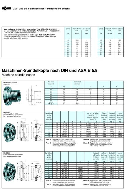
Max. zulässige Drehzahl für Planscheiben Type UGE-UGU, USE-USU<br />
Die angegebenen Werte sind nur zulässig für Werkstücke, die eine spezifische<br />
Unwucht von 25 gmm/kg nicht überschreiten.<br />
Max. permissible speeds for face plates type UGE-UGU, USE-USU<br />
The specified values are only applicable for work-pieces not exceeding a<br />
specific unbalance of 25 gmm/kg.<br />
DIN 800, mit Gewinde<br />
with thread<br />
3054<br />
Guß- und Stahlplanscheiben – Independent chucks<br />
DIN 55021<br />
ab Kegelgröße 4 mit Mitnehmer<br />
from taper size 4 with driver<br />
DIN 55026<br />
ab Kegelgröße 4 mit Mitnehmer<br />
from taper size 4 with driver<br />
Form A: Gewinde und Durchgangslöcher<br />
im Flansch (ohne inneren Lochkreis)<br />
Form B: Gewindelöcher und Durchgangslöcher<br />
im Flansch (äußerer Lochkreis) und<br />
Gewindelöcher im inneren Lochkreis<br />
Form A: Gewindelöcher im Flansch (äußerer<br />
Lochkreis) ohne inneren Lochkreis<br />
Form B: Gewindelöcher im Flansch (äußerer<br />
Lochkreis) und im inneren Lochkreis<br />
Größe Drehzahl min -1 / speed rpm<br />
Guß Stahl<br />
size cast iron steel<br />
150 1910 –<br />
200 1430 3000<br />
260 1150 2350<br />
310 960 1970<br />
350 820 1750<br />
400 720 1530<br />
450 640 1360<br />
500 570 1220<br />
560 520 1090<br />
Maschinen-Spindelköpfe nach DIN und ASA B 5.9<br />
Machine spindle noses<br />
Tol. mittel Kleinstmaß<br />
mean tol. minimum<br />
Größe Drehzahl min -1 / speed rpm<br />
Guß Stahl<br />
size cast iron steel<br />
600 470 1020<br />
630 430 970<br />
710 400 860<br />
800 350 765<br />
900 310 680<br />
1000 280 610<br />
1100 260 555<br />
1200 230 510<br />
A Bg5 C D E F<br />
M20 21 30 6,3 10 20<br />
M24 25 36 8 12 24<br />
M33 34 50 9 14 30<br />
M39 40 56 10 16 35<br />
M45 46 67 11 18 40<br />
M52 55 80 12 20 45<br />
M60 62 90 14 22 50<br />
M76x6 78 112 16 30 63<br />
M105x6 106 150 20 40 80<br />
Spindelkopf- Lochzahl auf äußer. Äußerer Lochzahl Innerer<br />
größe Lochkreis (F1) Lochkreis inn. Lochkr. Lochkreis<br />
spindle holes on outer bolt outer bolt Holes on Inner bolt<br />
nose size circle (F1) circle inn. bolt c. circle<br />
A B C D E1 G F1 (F2) E2 F2<br />
3 102 53,985 11 16 3xM10 3x10,5 75 – –<br />
4 112 63,525 11 20 3xM10 3x10,5 85 – –<br />
5 135 82,575 13 22 7xM10 4x10,5 104,8 8xM10 61,9<br />
6 170 106,390 14 25 7xM12 4x13 133,4 8xM12 82,6<br />
8 220 139,735 16 28 7xM16 4x17 171,4 8xM16 111,1<br />
11 290 196,885 18 35 12xM20 6x21 235 11xM20 165,1<br />
15 380 285,800 20 42 12xM24 6x25 330,2 11xM24 247,6<br />
20 520 412,800 21 48 12xM24 6x25 463,6 11xM24 368,3<br />
Shape A: Tapped holes and through-holes in<br />
flange (without inner bolt circle)<br />
Shape B: Tapped holes and through-holes in<br />
flange (outer bolt circle) and tapped<br />
holes in inner bolt circle<br />
Spindelkopf- Lochzahl äußerer Lochzahl Innerer<br />
größe äuß. Lochkr. Lochkreis inn. Lochkr. Lochkreis<br />
spindle Holes on outer bolt Holes on Inner bolt<br />
nose size out. bolt c. circle inn. bolt c. circle<br />
A B C C 1 D E1 F1 (F2) E2 F2<br />
3 92 53,983 11 – 16 3xM10 70,6 – –<br />
4 108 63,521 11 – 20 11xM10 82,6 – –<br />
5 133 82,573 13 14,288 22 11xM10 104,8 8xM10 61,9<br />
6 165 106,385 14 15,875 25 11xM12 133,4 8xM12 82,6<br />
8 210 139,731 16 17,462 28 11xM16 171,4 8xM16 111,1<br />
11 280 196,883 18 19,05 35 11xM20 235 8xM20 165,1<br />
15 380 285,791 19 20,638 42 12xM24 330,2 11xM24 247,6<br />
20 520 412,795 21 22,225 48 12xM24 463,6 11xM24 368,3<br />
Shape A: Tapped holes in flange (outer boltcircle)<br />
without inner bolt circle<br />
Shape B: Tapped holes in flange (outer bolt<br />
circle) and in inner bolt circle