Create successful ePaper yourself
Turn your PDF publications into a flip-book with our unique Google optimized e-Paper software.
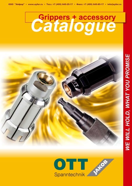
Grippers + accessory<br />
Catalogue<br />
WE WILL HOLD, WHAT YOU PROMISE
Clamping Technology<br />
Introduction<br />
2<br />
The name OTT has been standing<br />
for high technology for more than<br />
135 years. Meeting the customer´s<br />
requirements is our daily work. We<br />
are the right contact partner for you<br />
in the clamping sector. OTT stands<br />
for the state-of-the-art products. Our<br />
product´s flexibility and adaptability<br />
are the basis for satisfied customers<br />
throughout world.<br />
OTT-JAKOB´s products are exported<br />
worldwide. The implementation of<br />
our drawbars provides the evidence<br />
of good quality.<br />
Contents<br />
Tool Standard SK / Medium Transfer SK 3<br />
SK 30 4+5<br />
SK 40 6+7<br />
SK 50 8+9<br />
SK 50 (reinforced version) 10<br />
SK 60 11<br />
Measuring Device SK-Spindle-Edge 12<br />
HSK 13<br />
HSK standard (type K) 14+15<br />
HSK black (type B) 16+<strong>17</strong><br />
HSK 2S (type C) 18<br />
Repair-clamping-units 19<br />
Maintenance 20<br />
HSK spindle inside <strong>contour</strong> adapter 21<br />
Power Check 22+23
1<br />
2<br />
Tool Standard A<br />
DIN 69871 / 69872 ISO 7388 / 1 / 2 Typ A<br />
G H<br />
I<br />
+/- 0,<strong>25</strong> +/- 0,<strong>25</strong><br />
SK 30 31,75 71,65 66,65<br />
SK 40 44,45 94,<strong>25</strong> 88,<strong>25</strong><br />
SK 50 69,85 135,60 126,60<br />
SK 60 107,95 201,65 191,65<br />
C<br />
Tool Standard F Tool Standard E<br />
MAS 403-1982 BT/PT 1 (45°) MAS 403-1982 BT/PT 2 (30°)<br />
G L<br />
+/- 0,<strong>25</strong><br />
M<br />
+/- 0,<strong>25</strong><br />
SK 30 31,75 71,35 66,35<br />
SK 40 44,45 100,35 93,35<br />
SK 50 69,85 146,75 136,75<br />
Without medium transfer<br />
Axial medium transfer<br />
Tool Standard SK<br />
Tool Standard C<br />
ANSI B5.50-78 ISO 7388 / 1 / 2 Typ B<br />
G J<br />
+/- 0,30<br />
K<br />
+/- 0,30<br />
SK 30 31,75 59,30 55,65<br />
SK 40 44,45 84,50 79,<strong>25</strong><br />
SK 50 69,85 127,00 119,40<br />
SK 60 107,95 199,95 189,45<br />
Medium Transfer SK<br />
3<br />
4<br />
A<br />
F E<br />
Radial medium transfer<br />
Radial coolant transfer axial air transfer<br />
(transfer collar)<br />
Subject to modification due to technical advance! 3
SK 30<br />
4<br />
(only medium transfer 3)<br />
case-hardened<br />
edge rounded<br />
Tool Standard A C E F<br />
Form I<br />
Medium Transfer 1 / 2 / 3<br />
Pull force F E max. (N) 6000<br />
Stroke min. (mm) 5,5<br />
Ejection path (mm) 0,95 1,6 0,95 0,95<br />
Gauge dimension E.M. (mm) 70,7 57,7 70,4 70,4<br />
x 3,8 2,9 3,1 3,05<br />
L 1 57,1 69,8 57,8 57,8<br />
Order number<br />
Gripper with holder 95.101.452.3.2 95.101.450.3.2 95.101.453.3.2 95.101.451.3.2<br />
Mounting tool 95.101.280.9.2
ejection path<br />
E.M<br />
Gauge dimension to be<br />
adjusted only in unclamped<br />
position of the gripper.<br />
x<br />
L1<br />
(only medium transfer 3)<br />
F E max.<br />
Subject to modification due to technical advance!<br />
5
SK 40<br />
6<br />
X<br />
Y<br />
(only medium transfer 3/4)<br />
Tool Standard A A A A A A C<br />
Form I I I I II III I<br />
Medium Transfer 1 2 3 4 1/2 1/2 1<br />
Pull force F E max. (N)<br />
Stroke min. (mm)<br />
Ejection path (mm) 0,65<br />
Gauge dimension E.M. (mm) 93,6<br />
x 4 4 4 4 4 4 2,65<br />
L1 67,1 66,4 67,4 67,4 41,4 56,4 77,9<br />
Order number<br />
case-hardened<br />
Gripper with holder 95.101.288.3.2 95.101.216.3.2 95.101.202.3.2 95.101.223.3.2 95.101.684.3.2 95.101.570.3.2 95.101.287.3.2<br />
Lock screw 95.101.372.5.1 95.101.372.5.1 95.101.372.5.1 95.101.372.5.1 95.101.372.5.1<br />
Mounting tool 95.101.281.9.2 95.101.281.9.2 95.101.281.9.2 95.101.281.9.2 95.100.975.4.2 95.100.975.4.2 95.101.281.9.2<br />
Z<br />
edge rounded
X<br />
C C C C C E E F F<br />
I I I II III I II I II<br />
2 3 4 1/2 1/2 1/2 1/2 1/2 1/2<br />
15000<br />
5,5<br />
x<br />
x<br />
x<br />
E.M<br />
Gauge dimension to be adjusted only in<br />
unclamped position of the gripper.<br />
1,6 0,65<br />
82,9 99,7<br />
2,65 2,65 2,65 2,65 2,65 3,85 3,85 3,85 3,85<br />
77,5 77,9 78,2 51,6 67,3 60,3 35,3 60,3 35,3<br />
95.101.233.3.2 95.101.290.3.2 95.101.295.3.2 95.101.685.3.2 95.101.569.3.2 95.101.485.3.2 95.101.687.3.2 95.101.486.3.2 95.101.686.3.2<br />
95.101.372.5.1 95.101.372.5.1 95.101.372.5.1 95.101.372.5.1 95.101.372.5.1<br />
95.101.281.9.2 95.101.281.9.2 95.101.281.9.2 95.100.975.4.2 95.100.975.4.2 95.101.281.9.2 95.100.975.4.2 95.101.281.9.2 95.100.975.4.2<br />
ejection path<br />
E.M<br />
Gauge dimension to be adjusted only in<br />
unclamped position of the gripper.<br />
ejection path<br />
E.M<br />
Gauge dimension to be adjusted only in<br />
unclamped position of the gripper.<br />
ejection path<br />
Subject to modification due to technical advance!<br />
L1<br />
L1<br />
L1<br />
Holder to be adjusted only in<br />
unclamped position (by shim)<br />
7
SK 50<br />
8<br />
X<br />
case-hardened<br />
Tool Standard A A A A<br />
Form I I I II<br />
Medium Transfer 1/2 3 4 1/2<br />
Pull force F E max. (N)<br />
Stroke min. (mm)<br />
Ejection path (mm)<br />
Gauge dimension E.M. (mm) 134,6<br />
x 3,6 3,6 3,6 3,7<br />
L1 79,7 79,7 79,7 46,2<br />
Order number<br />
(only medium transfer 3/4)<br />
Y<br />
Gripper with holder 95.101.297.3.2 95.101.298.3.2 95.101.356.3.2 95.101.540.3.2<br />
Lock screw 95.103.636.5.1 95.103.636.5.1 95.103.636.5.1 95.103.636.5.1<br />
Mounting tool 95.101.337.9.2 95.101.337.9.2 95.101.337.9.2 95.101.337.9.2<br />
Z<br />
5<br />
edge rounded
ejection path<br />
E.M<br />
Gauge dimension to be adjusted only<br />
in unclamped position of the gripper.<br />
A C C C C E F<br />
III I I II III I I<br />
1/2 1/2 4 1/2 1/2 1/2 1/2<br />
<strong>25</strong>000<br />
6<br />
1<br />
126 145,75<br />
3,6 3,65 3,65 3,65 3,65 3,55 3,55<br />
66,8 87,9 87,9 55 75,9 68,8 68,8<br />
95.101.386.3.2 95.101.306.3.2 95.101.522.3.2 95.101.668.3.2 95.101.385.3.2 95.101.476.3.2 95.101.506.3.2<br />
95.103.636.5.1 95.103.636.5.1 95.103.636.5.1 95.103.636.5.1 95.103.636.5.1<br />
95.100.421.4.2 95.101.337.9.2 95.101.337.9.2 95.101.337.9.2 95.100.421.4.2 95.101.337.9.2 95.101.337.9.2<br />
E.M<br />
Gauge dimension to be adjusted only<br />
in unclamped position of the gripper.<br />
ejection path<br />
E.M<br />
Gauge dimension to be adjusted only<br />
in unclamped position of the gripper.<br />
ejection path<br />
Subject to modification due to technical advance!<br />
9
SK 50 (reinforced version)<br />
10<br />
Tool Standard A C<br />
Form I I<br />
Medium Transfer 1/2/3 1/2/3<br />
Pull force F E max. (N) 35000<br />
Stroke min. (mm) 9<br />
Ejection path (mm) 1<br />
Gauge dimension E.M. (mm) 134,6 126<br />
x 4,<strong>25</strong> 3,95<br />
L1 95 103,6<br />
Order number<br />
x<br />
(only for radial coolant transfer)<br />
Gripper with holder 95.101.781.3.2 95.101.782.3.2<br />
Lock screw 95.101.273.4.1 95.101.273.4.1<br />
Mounting tool 95.101.336.9.2 95.101.336.9.2<br />
Gauge dimension to be adjusted only in<br />
unclamped position of the gripper.<br />
ejection path<br />
edge rounded<br />
L1<br />
5<br />
case-hardened<br />
edge rounded
X<br />
Y Z<br />
Tool Standard A C<br />
Form I I<br />
Medium Transfer 1/2 1/2<br />
Pull force F E max. (N) 80000<br />
Stroke min. (mm) 8,5<br />
Ejection path (mm) 1,15 0,95<br />
Gauge dimension E.M. (mm) 200,5 199<br />
x 5,75 5,6<br />
L1 130,5 132,2<br />
Order number<br />
SK 60<br />
ejection path<br />
Gripper with holder 95.101.308.3.2 95.101.307.3.2<br />
Lock screw 95.101.092.4.1 95.101.092.4.1<br />
Mounting tool 95.101.284.9.2 95.101.284.9.2<br />
Gauge dimension to be adjusted only in<br />
unclamped position of the gripper.<br />
Subject to modification due to technical advance!<br />
L1<br />
case-hardened<br />
11
Measuring Device<br />
SK-Spindle-Edge<br />
12<br />
Use the measuring device for measuring:<br />
• the position of the diameter d<br />
• the measure l<br />
Size l Ø d Ød4 Tool Standard Order number<br />
SK30<br />
universal<strong>contour</strong><br />
SK40<br />
universal<strong>contour</strong><br />
SK50<br />
universal<strong>contour</strong><br />
SK60<br />
universal<strong>contour</strong><br />
59 31,75 22,5<br />
79,5 44,45 34<br />
116,5 69,85 49<br />
181,3 0 65<br />
DIN 69871 / 69872 //<br />
ISO 7388 / 1 / 2 type A<br />
ANSI B 5.50 – 1978 //<br />
ISO 7388 / 1 / 2 type B<br />
MAS 403-1982 BT/PT 30° / 45°<br />
DIN 69871 / 69872 //<br />
ISO 7388 / 1 / 2 type A<br />
DIN 2080 OTT-Rille<br />
ANSI B 5.50 – 1978 //<br />
ISO 7388 / 1 / 2 type B<br />
MAS 403-1982 BT/PT 30° / 45°<br />
DIN 69871 / 69872 // ISO 7388<br />
/ 1 / 2 type A<br />
DIN 2080 OTT-Rille<br />
ANSI B 5.50 – 1978 // ISO<br />
7388 / 1 / 2 type B<br />
MAS 403-1982 BT/PT 30° / 45°<br />
DIN 69871 / 69872 //<br />
ISO 7388 / 1 / 2 type A<br />
ANSI B 5.50 – 1978 //<br />
ISO 7388 / 1 / 2 type B<br />
max. allowable<br />
deviation of gage<br />
dimension measured<br />
from the spindle face:<br />
±0,1 mm<br />
95.102.575.3.2<br />
95.100.120.3.2<br />
95.101.270.3.2<br />
95.101.274.2.2
HSK<br />
HSK CLAMPING SYSTEM FOR AUTOMATICTOOL CHANGE<br />
(DIN 69893)<br />
Studies at the RWTH-Aachen and customer<br />
applications have shown significant advantages<br />
in precision and stiffness of the HSK-interface<br />
compared to the steep taper interface.<br />
- Higher position accuracy of the tool due to<br />
axial face and taper position.<br />
- Ideal for high speed machining.<br />
- Easy tool handling due to low weight and<br />
dimensions of the short taper.<br />
- Heavy duty chip removal can be achieved<br />
through total stiffness of the Interface,high pull<br />
forces and the resulting transmittable torque.<br />
The automatic interfaces HSK <strong>25</strong> - HSK 160 are<br />
available in 4 forms:<br />
- Form A<br />
Is the most common tool standard with internal<br />
drive keys.<br />
- Form B:<br />
Has external drive keys, a larger flange dia-<br />
meter, and is used mainly for heavy duty chip<br />
removal.<br />
- Form E:<br />
Without drive key, is used for high speed<br />
operation.<br />
- Form F:<br />
Has no sealing against coolant and is used<br />
mainly in the wood working and plastic<br />
industry.<br />
All automatic tool clamping systems<br />
(Form A / B / E / F) are equipped<br />
with the patented OTT-JAKOB<br />
gripper geometry. This <strong>contour</strong><br />
allows to triple the transmittance of<br />
the pull force. The forces therefore,<br />
occur mainly in the interface area<br />
of the spindle.<br />
Subject to modification due to technical advance!<br />
13
HSK standard (type K)<br />
14<br />
d 1<br />
1<br />
SW<br />
A<br />
H0 H1 Hmax. E.M. = Gauge Einstellmaß ejection path to be adjusted only<br />
in unclamped position of the gripper<br />
A = Ausstoß ejection path<br />
a 1<br />
Features<br />
• Parallel moving gripper segments<br />
• High static and dynamic stiffness<br />
l 7<br />
6<br />
d<br />
Limit Zugstangenhub the stroke begrenzen of drawbar auf shaft Hmax.! to H ! max.
Type E<strong>25</strong><br />
A32<br />
B40<br />
E32<br />
A40<br />
B50<br />
E40<br />
F50<br />
A50<br />
B63<br />
E50<br />
F63<br />
A63<br />
B80<br />
E63<br />
F80<br />
A80<br />
B100<br />
A100<br />
B1<strong>25</strong><br />
A1<strong>25</strong><br />
B160 A160<br />
Clamping force F max. (N)* 2800 5000 6800 11000 18000 28000 45000 70000 115000<br />
Stroke max. (mm) 7,0 7,5 8,0 9,0 10,0 11,0 12,5 15,8 24,5<br />
E.M. +/- 0,1 (mm) 6,5 8,5 8,5 10,5 10,5 13,0 13,0 16,5 <strong>17</strong>,0<br />
Ejection (mm) 0,5 0,5 0,5 0,5 0,5 0,5 0,5 0,5 1,0<br />
FSpring (N) 980 <strong>17</strong>50 2400 3850 6000 9200 15000 24500 40000<br />
Stroke with tool 4,6 5,1 5,6 6,4 7,4 8,3 9,15 10,8 <strong>17</strong>,5<br />
Lock screw SW 3 SW 3 SW 4 SW 4 SW 5 SW 6 SW 6 SW 14 SW 16<br />
sw1 SW 10 SW 12 SW 15 SW 18 SW 22 SW 27 SW 36 SW 46 SW 55<br />
a1 5,5 19,5 27 26,5 31,5 31,5 34,5 40,5 56<br />
d1 min.<br />
A / E<br />
B / F<br />
<strong>25</strong> 32<br />
40<br />
40<br />
50<br />
50<br />
63<br />
63<br />
80<br />
80<br />
100<br />
100<br />
1<strong>25</strong><br />
1<strong>25</strong><br />
160<br />
160<br />
d6 14 <strong>17</strong> 21 26 34 42 53 67 85<br />
l7 40 62,5 78 84 94 98 124 149 188<br />
Order number<br />
Clamping unit 95.600.011.3.6 95.600.008.3.6 95.600.007.3.6 95.600.004.3.6 95.600.001.3.6 95.600.002.3.6 95.600.003.3.6 95.600.009.3.6 95.600.010.3.6<br />
F50 =<br />
95.600.016.3.6<br />
F63 =<br />
95.600.083.3.2<br />
F80 =<br />
95.600.015.3.6<br />
Lock screw 95.600.271.4.1 95.600.121.4.1 95.600.122.4.1 95.101.597.5.1 95.101.372.5.1 95.103.636.5.1 95.103.636.5.1 95.600.101.4.1 95.600.372.4.1<br />
Mounting tool 95.601.561.3.2 95.601.111.3.1 95.601.112.3.1 95.601.113.3.1 95.601.114.3.1 95.601.115.2.1 95.601.116.2.1 95.601.1<strong>17</strong>.2.1 95.601.118.2.1<br />
* The clamping forces in this table are the standard forces.<br />
Our HSK clamping units can realize much higher clamping forces.<br />
Please contact us for further information.<br />
Änderungen im Subject Sinne des to modification technischen due Fortschrittes to technical vorbehalten! advance! 15
HSK black (type B)<br />
16<br />
A shorter tool changing time represents a constant challenge, which even increased with HSCmanufacturing.<br />
Fast working automatic clamping systems are necessary which have to be more<br />
accurate, rigid and universal than conventional systems. OTT-JAKOB met these requirements by<br />
developing a complete new HSC-clamping unit.<br />
Bronze bushing<br />
to conserve the coolant pipe.<br />
Advanced coating technology<br />
for lifetime function under difficult circumstances.<br />
Performed an extensive test<br />
over 9 million cycles with a cycle time<br />
of only 0,13 seconds.<br />
The locking geometry<br />
guarantees trouble free clamping and unclamping.<br />
Features<br />
• Parallel moving gripper segments<br />
• High static and dynamic stiffness<br />
• Locking geometry<br />
• High life expectancy<br />
In our company in Lengenwang several clamping units were clamped and unclamped up to 9 million<br />
times with a speed of 0.13 seconds. The wear was minimal and the clamping force reduction<br />
insignificant.<br />
The OTT-JAKOB HSK clamping unit type B has a controlled movement of the fingers and guarantees<br />
safe clamping and unclamping of the tool. Fastest clamping is thus only a topic of the control<br />
and the process optimization in the machine software.
Type E<strong>25</strong><br />
A32<br />
B40<br />
E32<br />
A40<br />
B50<br />
E40<br />
F50<br />
* The clamping forces in this table are the standard forces.<br />
Our HSK clamping units can realize much higher clamping forces.<br />
Please contact us for further information.<br />
A50<br />
B63<br />
E50<br />
F63<br />
A63<br />
B80<br />
E63<br />
F80<br />
A80<br />
B100<br />
A100<br />
B1<strong>25</strong><br />
Clamping force F max. N)* 2800 5000 6800 11000 18000 28000 45000<br />
Stroke max. (mm) 7,0 7,5 8,0 9,0 10,0 11,0 12,5<br />
E.M. +/- 0,1 (mm) 6,5 8,5 8,5 10,5 10,5 13,0 13,0<br />
Ejection (mm) 0,5 0,5 0,5 0,5 0,5 0,5 0,5<br />
FSpring (N) 980 <strong>17</strong>50 2400 3850 6000 9200 15000<br />
Stroke with tool 4,6 5,1 5,6 6,4 7,4 8,3 9,15<br />
Lock screw SW 3 SW 3 SW 4 SW 4 SW 5 SW 6 SW 6<br />
sw1 SW 10 SW 12 SW 15 SW 18 SW 22 SW 27 SW 36<br />
a1 5,5 19,5 27 26,5 31,5 31,5 34,5<br />
d1 min.<br />
A / E<br />
B / F<br />
<strong>25</strong> 32<br />
40<br />
40<br />
50<br />
50<br />
63<br />
63<br />
80<br />
80<br />
100<br />
100<br />
1<strong>25</strong><br />
d6 14 <strong>17</strong> 21 26 34 42 53<br />
l7 40 62,5 78 84 94 98 124<br />
Order number<br />
Clamping unit 95.600.038.3.6 95.600.113.3.6 95.600.034.3.6 95.600.035.3.6 95.600.033.2.6 95.600.036.2.6 95.600.037.2.6<br />
Lock screw 95.600.271.4.1 95.600.121.4.1 95.600.122.4.1 95.101.597.5.1 95.101.372.5.1 95.103.636.5.1 95.103.636.5.1<br />
Subject to modification due to technical advance! <strong>17</strong>
HSK 2S (type C)<br />
18<br />
The HSK clamping unit 2S (2 Step) is the next<br />
generation of OTT-JAKOB clamping units. This<br />
clamping unit features a holding function for the<br />
tool. When the clamping unit is positioned for<br />
tool change, the tools are held by a specified<br />
force in the tool changeposition. With automatic<br />
tool changing, the tool changer must be rigidly<br />
designed to withstand the tool pull forces.<br />
All types of clamping units of the same size will<br />
fit in the same spindle <strong>contour</strong>.<br />
Features<br />
• Parallel moving gripper segments<br />
• High static and dynamic stiffness<br />
• Locking geometry<br />
• High life expectancy<br />
• Tool holding function
If fashioning necessary (fashioning receiver),<br />
we have repair-clamping-units.<br />
Nominal size<br />
at<br />
Clamping unit<br />
HSK B<br />
Repair-clamping-units<br />
Repair-clamping-units<br />
HSK B-E 0,3<br />
Repair-clamping-units<br />
HSK B-E 0,6<br />
complete l 9 complete l 9 complete l 9<br />
E<strong>25</strong> 95.600.038.3.6 18,5 95.600.071.9.6 18,2 95.600.087.9.6 <strong>17</strong>,9<br />
A32 / B40 / E32 95.600.113.3.6 30,0 95.600.072.9.6 29,7 95.600.088.9.6 29,4<br />
A40 / B50 / E40 95.600.034.3.6 44,0 95.600.073.9.6 43,7 95.600.090.9.6 43,4<br />
A50 / B63 / E50 95.600.035.3.6 45,0 95.600.074.9.6 44,7 95.600.091.9.6 44,4<br />
A63 / B80 / E63 95.600.033.2.6 52,0 95.600.075.9.6 51,7 95.600.095.9.6 51,4<br />
A80 / B100 95.600.036.2.6 56,0 95.600.076.9.6 55,7 95.600.096.9.6 55,4<br />
A100 / B1<strong>25</strong> 95.600.037.2.6 70,0 95.600.077.9.6 96,7 95.600.097.9.6 69,4<br />
Subject to modification due to technical advance!<br />
19
Maintenance HSK<br />
20<br />
Preventive maintenance schedule<br />
To guarantee the function of the power drawbar the following preventive maitenance<br />
schedule must be adhered to.<br />
Every week<br />
- Check the packing ring in the clamping unit (visual check)<br />
- Check the gripper, is it damaged or dirty, is it sufficient greased (visual check)<br />
Pay attention to:<br />
The regrease cycle depends on the loss of lubrication of the clamping unit.<br />
Cause for the loss of lubricationg:<br />
• Seal in the clamping cone is defective<br />
• Type of medium used can desolve grease<br />
• Cleaning spray from outside directly on the clamping unit etc.<br />
- Note: METAFLUX Moly-Spray No.70-82 is recommended for a quick regreasing<br />
of the clamping unit without gripper-disassembly.<br />
Every six month or after 200.000 tool changes at the latest<br />
- In unclamped position: Check dimension gauge E.M.<br />
- counter through a clamped tool again<br />
- Test Pull-in-force (we recommend:use Power-Check):<br />
If the pull-in-force is smaller than 70% of the nominal value, following procedures<br />
have to be performed in the following sequence:<br />
• regrease and test pull-in force again<br />
• exchange gripper and test again<br />
• exchange drawbar completely<br />
Every year or after 500.000 tool changes at the latest<br />
- Exchange the packing ring<br />
Grease for HSK-calmping unit<br />
Name Quantity Order number<br />
METAFLUX-grease-paste Nr. 70-8508* 4 g 0.929100.012<br />
METAFLUX-moly-spray Nr. 70-82 400 ml 06.21001.010<br />
KLÜBER-grease-paste ME 31-52 10 g 06.21001.014<br />
KLÜBER-spray ALTEMP Q NB 50 400 ml 06.21001.015<br />
Aid for regreasing with paste in mounted state (clamped without tool):<br />
Name HSK-size Order number<br />
brush A50 - A100 06.16001.001<br />
* original lubrication and first equipment<br />
Note: take only grease of one company; do<br />
not mix the grease!
Nominal size „reference length“ Order number<br />
l 9 js8<br />
(at d 3 )<br />
E <strong>25</strong> 18,5 ±0,0165 (14) 95.601.342.3.2<br />
A 32 / B 40 / E 32 30 ±0,0165 (<strong>17</strong>) 95.601.340.3.2<br />
A 40 / B 50 / E 40 44 ±0,0195 (21) 95.601.332.3.2<br />
A 50 / B 63 / E 50 / F 63 45 ±0,0195 (26) 95.601.322.3.2<br />
A 63 / B 80 / E 63 / F 80 52 ±0,023 (34) 95.600.760.3.2<br />
A 80 / B 100 56 ±0,023 (42) 95.601.358.3.2<br />
A 100 / B 1<strong>25</strong> 70 ±0,023 (53) 95.601.361.3.2<br />
A 1<strong>25</strong> / B 160 86 ±0,027 (67) 95.601.361.3.2<br />
A 160 113 ±0,027 (85) 95.601.363.3.2<br />
A 50 short / B 63 short /<br />
E 50 short / F 63 short<br />
31,5 ±0,0195 (26) 95.601.329.3.2<br />
A 63 short 40 ±0,0195 (34) 95.600.898.3.2<br />
A 63 short - 38 38 ±0,0195 (34) 95.601.204.3.2<br />
Procedure for setting gage Inner <strong>contour</strong> measuring<br />
actual value<br />
Measuring Device<br />
HSK-Spindle-Edge<br />
at<br />
Subject to modification due to technical advance!<br />
21
Power Check<br />
22<br />
The power check is a measuring device used<br />
check the force with which the tool is being pulled<br />
into the spindle taper. The specified pull force is<br />
very important for the quality of machining.<br />
If the pull force falls below a specified value<br />
which will eventually occur due to mechanical<br />
fatigue (e.g. spring wear, breakage, etc.). Then<br />
one or more of the following will result<br />
• tool wear will significantly increase<br />
• the tool vibrates and leaves a bad surface<br />
finish<br />
• fretting occurs in the spindle taper and tool<br />
holders<br />
• unexpected tool breakage<br />
• reduced tool life<br />
• safety of the machine operator is at risk<br />
Including the power check into your preventive<br />
maintenance schedule will allow you to notice a<br />
reduction of the pull force and prevent the above<br />
mentioned problems before they occur. Early<br />
preventive actions can be taken to:<br />
• avoid unnecessary machine shut down<br />
• avoid a number of blurry problems, which can<br />
not be defined (e.g. excessive tool wear, loss of<br />
tool life, and tool breakage)<br />
Advantage<br />
• Suitable for all types of clamping systems<br />
regardless of manufactures<br />
• can be used for all tapered standards and sizes<br />
(SK, ANSI, BT, MAS, HSK, and special stan-<br />
dards) simply by exchanging out the adapters<br />
• the system is light, compact, and very easy to<br />
use. It is used like a tool<br />
• the pull force is easily read on the LCD display<br />
in kN and klb<br />
• the standard 9 volt DC battery<br />
• the machining tolerance of the spindle<br />
taper and tool taper can be compensated<br />
by the power check. The tolerance<br />
range can be adjusted according<br />
to the standard + or -<br />
(1mm increments)<br />
• two versions are available:<br />
- pull force from 2 to 15 kN<br />
- pull force from 10 to 75 kN
Base unit<br />
Measuring range Order number<br />
10 - 75 kN 95.101.600.2.2<br />
2 - 15 kN 95.101.712.2.2<br />
Adapter Norm Order number<br />
SK 30<br />
SK 40<br />
SK 45<br />
SK 50<br />
SK 60<br />
HSK<br />
Capto<br />
ISO DIN 69871/872 95.101.582.9.2<br />
ANSI B 5.50 95.101.583.9.2<br />
MAS 403/45 BT/PT 1 95.101.584.9.2<br />
MAS 403/30 BT/PT 2 95.101.585.9.2<br />
DIN 2080 95.101.6<strong>25</strong>.9.2<br />
ISO DIN 69871/872 95.101.586.9.2<br />
ANSI B 5.50 95.101.587.9.2<br />
MAS 403/45 BT/PT 1 95.101.588.9.2<br />
MAS 403/30 BT/PT 2 95.101.589.9.2<br />
MAS 403/0 95.101.694.9.2<br />
DIN 2080 95.101.626.9.2<br />
ISO DIN 69871/872 95.101.590.9.2<br />
ANSI B 5.50 95.101.591.9.2<br />
MAS 403/45 BT/PT 1 95.101.592.9.2<br />
MAS 403/30 BT/PT 2 95.101.593.9.2<br />
DIN 2080 95.101.627.9.2<br />
ISO DIN 69871/872 95.101.594.9.2<br />
ANSI B 5.50 95.101.595.9.2<br />
MAS 403/45 BT/PT 1 95.101.596.9.2<br />
MAS 403/30 BT/PT 2 95.101.597.9.2<br />
MAS 403/0 95.101.662.9.2<br />
DIN 2080 95.101.628.9.2<br />
ISO DIN 69871/872 95.101.598.9.2<br />
ANSI B 5.50 95.101.599.9.2<br />
MAS 403/45 BT/PT 1 95.101.601.9.2<br />
MAS 403/30 BT/PT 2 95.101.602.9.2<br />
E <strong>25</strong> / F 32 95.600.069.9.2<br />
A 32 / B 40 / E 32 / F 40 95.600.070.9.2<br />
A 40 / B 50 / E 40 / F 50 95.600.071.9.2<br />
A 50 / B 63 / E 50 / F 63 95.600.072.9.2<br />
A 63 / B 80 / E 63 / F 80 95.600.073.9.2<br />
A 80 / B 100 95.600.074.9.2<br />
A 100 / B 1<strong>25</strong> 95.600.075.9.2<br />
A 1<strong>25</strong> / B 160 95.600.076.9.2<br />
C4 ISO 95.601.481.9.2<br />
C5 ISO 95.601.482.9.2<br />
C6 ISO 95.601.266.9.2<br />
C8 ISO 95.601.483.9.2<br />
Subject to modification due to technical advance! 23
95.102.005.P.E 06/2009<br />
Complete<br />
Systems<br />
Standardization requires meeting the needs of the user. The Ott universal<br />
inside spindle <strong>contour</strong> is an important step towards modular tooling.<br />
It offers the manufacturer of machines and /or spindle units the ability to<br />
clamp different steep taper tools (taper/retention knob standard) simply<br />
by exchanging the gripper unit.<br />
Several variations of power drawbars with or without coolant, with<br />
hydraulic or pneumatic unclamp units can be built into the same spindles.<br />
Our rotary unions and unclamp units together with our clamping systems<br />
and the original OTT-JAKOB HSK-clamping units form a unbeatable<br />
team.<br />
OTT-JAKOB HSK clamping units:<br />
Trust the original in all it’s variations<br />
OTT-JAKOB rotary unions:<br />
1 and 2 channel rotary unions. We offer the right rotary union for your<br />
case of application.<br />
OTT-JAKOB unclamp units:<br />
Hydraulic or pneumatic unclamping.<br />
OTT-JAKOB Power Check:<br />
A measuring device used check the force with which the tool is being<br />
pulled into the spindle taper.<br />
OTT-JAKOB Position Controller:<br />
The position-controller is a module of the OTT-JAKOB position monitoring<br />
system.<br />
OTT-JAKOB<br />
Spanntechnik GmbH<br />
Industriestraße 3 - 7<br />
D - 87663 Lengenwang<br />
+49 (0) 83 64 / 98 21- 0<br />
+49 (0) 83 64 / 98 21- 10<br />
info@ott-jakob.de<br />
http://www.ott-jakob.de<br />
WE WILL HOLD, WHAT YOU PROMISE


