CONCENTO PLUS Technisches Handbuch - Tunstall GmbH
CONCENTO PLUS Technisches Handbuch - Tunstall GmbH
CONCENTO PLUS Technisches Handbuch - Tunstall GmbH

Sie wollen auch ein ePaper? Erhöhen Sie die Reichweite Ihrer Titel.
YUMPU macht aus Druck-PDFs automatisch weboptimierte ePaper, die Google liebt.
<strong>Tunstall</strong> <strong>GmbH</strong>, Orkotten 66, D-48291 Telgte, www.tunstall.de<br />
Installationsanleitung D Installation Instructions GB<br />
Zimmerleuchte Universal, 3-teilig, mit Türschild, Best.‐Nr. 77 0181 10<br />
zur optischen Anzeige von allen Rufarten, Personalanwesenheit 1 und zusätzlich WC‐Ruf.<br />
Türschild als Beschriftungsfeld für die Raumbezeichnung. Wandmontage.<br />
Zimmerleuchte Universal, 4-teilig, mit Türschild, Best.‐Nr. 77 0181 00<br />
wie 77 0181 10, jedoch zusätzlich mit Personalanwesenheit 2.<br />
Achtung! Die LED‐Module sind mit elektrostatisch gefährdeten Bauteilen bestückt.<br />
Vermeiden Sie deshalb eine direkte Berührung.<br />
Anschlüsse Connections<br />
System EccoLine L200, NewLine L200: System CCS:<br />
Terminal L200<br />
00 8802 55, 12/11 (Rev. 1.1)<br />
0V<br />
RL<br />
AWL<br />
WCL<br />
COM<br />
L1<br />
L2<br />
L3<br />
L4<br />
LB1<br />
LB2<br />
ComTerminal<br />
*nur bei 77 0181 00<br />
*only for 77 0181 00<br />
Room lamp universal, 3 sections, with doorplate, order no. 77 0181 10<br />
for optical signalling of all call types, staff presence 1 and additional display for WC call.<br />
Doorplate as label field for room designation. Wall mounting.<br />
Room lamp universal, 4 sections, with doorplate, order no. 77 0181 00<br />
as 77 0181 10, but additionally with staff presence 2.<br />
0V<br />
C<br />
S<br />
HS*<br />
WL<br />
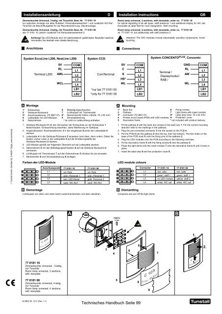
Montage Mounting<br />
1* Einbaudose<br />
2 Gehäuse‐Rückwand<br />
3* Anschlussklemme (70 0807 07)<br />
4 Leiterplatte mit LED‐Modulen<br />
5 Dekorrahmen<br />
6 Befestigungsschrauben<br />
7 Lichtkuppel mit Trenneinsatz<br />
8* Namensschild (Höhe x Breite: 70 x 92 mm)<br />
9 Schutzabdeckung<br />
* ist nicht im Lieferumfang enthalten.<br />
1. Gehäuse‐Rückwand 2 mit den Schrauben der Einbaudose an der Einbaudose 1<br />
festschrauben. Einbaurichtung beachten, siehe Markierung im Gehäuse.<br />
2. Angeschlossene Anschlussklemme 3 in die eingebaute Buchse der Leiterplatte 4<br />
stecken.<br />
3. Leiterplatte 4 in die Gehäuse‐Rückwand 2 einsetzen (erst oben, dann unten). Dabei die<br />
beiden Löcher unten in der Leiterplatte 4 auf die Arretierungsstifte der<br />
Gehäuse‐Rückwand 2 stecken.<br />
4. LED‐Module gemäß der folgenden Übersicht auf die Leiterplatte stecken.<br />
5. Dekorrahmen 5 mit den Befestigungsschrauben 6 auf die Gehäuse‐Rückwand 2<br />
schrauben.<br />
6. Lichtkuppel mit Trenneinsatz 7 auf den Dekorrahmen 5 drücken bis sie einrastet.<br />
7. Namenschild 8 und Schutzabdeckung 9 einlegen.<br />
Attention! The LED modules include electrostatic sensitive components. Avoid<br />
touching.<br />
COM<br />
L1<br />
L2<br />
L3<br />
L4<br />
LB1<br />
LB2<br />
Farben der LED‐Module LED module colours<br />
Anschlusspunkt<br />
L1<br />
L2<br />
L3<br />
L4<br />
77 0181 10 77 0181 00<br />
rot: Rufe<br />
rot: Rufe<br />
grün: Personal 1 grün: Personal 1<br />
kein LED‐Modul gelb: Personal 2<br />
weiß: WC‐Ruf weiß: WC‐Ruf<br />
Demontage Dismantling<br />
System <strong>CONCENTO</strong> <strong>PLUS</strong> , Concento:<br />
Terminal /<br />
Displaymodul /<br />
RAB /<br />
GND<br />
RL<br />
AW<br />
WL<br />
COM<br />
L1<br />
L2<br />
L3<br />
L4<br />
LB1<br />
LB2<br />
1* Back box<br />
6 Fixing screws<br />
2 Pattress<br />
7 Light dome with insert module<br />
3* Connector (70 0807 07)<br />
8* Label strip (hxw: 70 x 92 mm)<br />
4 Printed circuit board (PCB) with LED modules 9 Protection cover<br />
5 Decorative frame<br />
* not included with product delivery.<br />
1. Fit the pattress 2 with the back box screws to the back box 1. For the correct mounting<br />
direction refer to the markings in the pattress.<br />
2. Plug the pre-connected connector 3 into the socket on the PCB 4.<br />
3. Put the PCB 4 into the pattress 2 (first the top, then the bottom). The two holes on the<br />
base of the PCB must fit onto the fixing pins of the pattress 2.<br />
4. Plug the LED modules onto the PCB according to the following overview.<br />
5. Fit the decorative frame 5 with the fixing screws 6 onto the pattress 2.<br />
6. Press the light dome with the insert module 7 onto the decorative frame 5 until it locks in<br />
place.<br />
7. Insert the label strip 8 and the protection cover 9.<br />
Connector<br />
L1<br />
L2<br />
L3<br />
L4<br />
Lichtkuppel von oben und unten leicht zusammendrücken und dann abziehen. Compress and pull off the light dome.<br />
77 0181 10<br />
Zimmerleuchte Universal , 3‐teilig,<br />
mit Türschild<br />
Room lamp universal, 3 sections,<br />
with doorplate<br />
77 0181 00<br />
Zimmerleuchte Universal, 4‐teilig,<br />
mit Türschild<br />
Room lamp universal, 4 sections,<br />
with doorplate<br />
1<br />
2<br />
3<br />
OBEN<br />
TOP<br />
<strong>Technisches</strong> <strong>Handbuch</strong> Seite 99<br />
4<br />
5<br />
6<br />
6<br />
8<br />
9<br />
77 0181 10 77 0181 00<br />
red: calls red: calls<br />
green: staff 1 green: staff 1<br />
no LED module yellow: staff 2<br />
white: WC call white: WC call<br />
7<br />
1.<br />
1.<br />
2.