RADEMACHER RolloPort S1 650N-2 Garagentorantrieb (46026571)
RADEMACHER RolloPort S1 650N-2 Garagentorantrieb (46026571)
RADEMACHER RolloPort S1 650N-2 Garagentorantrieb (46026571)

Erfolgreiche ePaper selbst erstellen
Machen Sie aus Ihren PDF Publikationen ein blätterbares Flipbook mit unserer einzigartigen Google optimierten e-Paper Software.
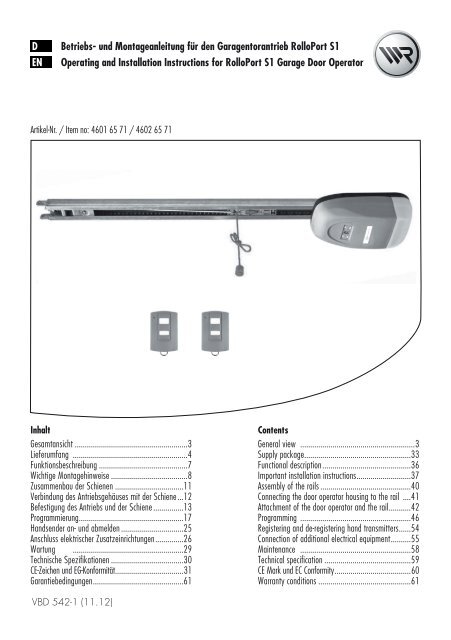
D Betriebs- und Montageanleitung für den <strong>Garagentorantrieb</strong> <strong>RolloPort</strong> <strong>S1</strong><br />
EN Operating and Installation Instructions for <strong>RolloPort</strong> <strong>S1</strong> Garage Door Operator<br />
Artikel-Nr. / Item no: 4601 65 71 / 4602 65 71<br />
Inhalt<br />
Gesamtansicht ........................................................3<br />
Lieferumfang .........................................................4<br />
Funktionsbeschreibung ............................................7<br />
Wichtige Montagehinweise ......................................8<br />
Zusammenbau der Schienen ..................................11<br />
Verbindung des Antriebsgehäuses mit der Schiene ...12<br />
Befestigung des Antriebs und der Schiene ...............13<br />
Programmierung ....................................................17<br />
Handsender an- und abmelden ...............................25<br />
Anschluss elektrischer Zusatzeinrichtungen ..............26<br />
Wartung .......................................................29<br />
Technische Spezifikationen ....................................30<br />
CE-Zeichen und EG-Konformität..................................31<br />
Garantiebedingungen .............................................61<br />
VBD 542-1 (11.12)<br />
Contents<br />
General view .........................................................3<br />
Supply package.....................................................33<br />
Functional description ............................................36<br />
Important installation instructions ...........................37<br />
Assembly of the rails .............................................40<br />
Connecting the door operator housing to the rail ....41<br />
Attachment of the door operator and the rail ...........42<br />
Programming .......................................................46<br />
Registering and de-registering hand transmitters ......54<br />
Connection of additional electrical equipment ..........55<br />
Maintenance .......................................................58<br />
Technical specification ...........................................59<br />
CE Mark und EC Conformity ......................................60<br />
Warranty conditions ..............................................61
2<br />
i<br />
Sehr geehrte Kunden...<br />
...mit dem Kauf dieses <strong>Garagentorantrieb</strong>s haben<br />
Sie sich für ein Qualitätsprodukt aus dem Hause<br />
<strong>RADEMACHER</strong> entschieden. Wir danken Ihnen für Ihr<br />
Vertrauen.<br />
i Diese Anleitung...<br />
i Zeichenerklärung<br />
...beschreibt Ihnen die Montage,<br />
den elektrischen Anschluss und die<br />
Bedienung des <strong>RolloPort</strong> <strong>S1</strong>.<br />
Bitte lesen Sie diese Anleitung vollständig durch und<br />
beachten Sie alle Sicherheitshinweise, bevor Sie mit<br />
den Arbeiten beginnen.<br />
Bitte bewahren Sie diese Anleitung auf und übergeben<br />
Sie die Anleitung bei einem Besitzerwechsel auch dem<br />
Nachbesitzer.<br />
Bei Schäden, die durch Nichtbeachtung dieser Anleitung<br />
und der Sicherheitshinweise entstehen, erlischt die<br />
Garantie. Für Folgeschäden, die daraus resultieren,<br />
übernehmen wir keine Haftung.<br />
STOP<br />
Der <strong>RADEMACHER</strong> <strong>Garagentorantrieb</strong><br />
ist unter<br />
Aspekten des größten<br />
Komforts entstanden. Mit<br />
einem kompromisslosen<br />
Qualitätsanspruch und nach<br />
langen Versuchsreihen sind<br />
wir stolz, Ihnen dieses<br />
innovative Produkt zu präsentieren.<br />
Dahinter stehen alle hochqualifiziertenMitarbeiterinnen<br />
und Mitarbeiter aus<br />
dem Hause <strong>RADEMACHER</strong>.<br />
Lebensgefahr durch Stromschlag<br />
Dieses Zeichen weist Sie auf Gefahren bei Arbeiten an<br />
elektrischen Anschlüssen, Bauteilen etc. hin. Es fordert<br />
Sicherheitsmaßnahmen zum Schutz von Gesundheit und<br />
Leben der betroffenen Person.<br />
Hier geht es um Ihre Sicherheit.<br />
Beachten und befolgen Sie bitte alle so gekennzeichneten<br />
Hinweise.<br />
So warnen wir vor Fehlverhalten, das zu<br />
Personen- oder Sachschäden führen kann.<br />
HINWEIS/WICHtIG/ACHtuNG<br />
Auf diese Weise machen wir Sie auf weitere, für die<br />
einwandfreie Funktion, wichtige Inhalte aufmerksam.<br />
D
3<br />
i<br />
Gesamtansicht / General View<br />
3<br />
6 7 8<br />
10 9<br />
4<br />
5<br />
2<br />
1<br />
D<br />
EN<br />
Legende<br />
1 = Antrieb, inkl. Beleuchtung<br />
2 = Handsender<br />
3 = LED<br />
4 = 1. Taste des Handsenders<br />
5 = 2. Taste des Handsenders<br />
6 = Set-Taste (S)<br />
7 = Anzeige<br />
8 = Einstellungstaste (+)<br />
9 = Einstellungstaste (-)<br />
10 = Programmiertaste (P)<br />
Key<br />
1 = Operator, including lighting<br />
2 = Hand transmitter<br />
3 = LED<br />
4 = 1st hand transmitter button<br />
5 = 2nd hand transmitter button<br />
6 = Set button (S)<br />
7 = Display<br />
8 = Button for adjustment (+)<br />
9 = Button for adjustment (-)<br />
10 = Programming button (P)<br />
D<br />
EN
1.<br />
2.<br />
3.<br />
4.<br />
5.<br />
6.<br />
7.<br />
8.<br />
9.<br />
4<br />
i<br />
Lieferumfang<br />
D Betriebs- und Montageanleitung für den <strong>Garagentorantrieb</strong> <strong>RolloPort</strong> <strong>S1</strong><br />
EN Operating and Installation Instructions for <strong>RolloPort</strong> <strong>S1</strong> Garage Door Operator<br />
Artikel-Nr. / Item no: 4601 65 71 / 4602 65 71<br />
Contents<br />
General view .........................................................3<br />
Supply package.....................................................33<br />
Functional description ............................................36<br />
Important installation instructions ...........................37<br />
Assembly of the rails .............................................40<br />
Connecting the door operator housing to the rail ....41<br />
Attachment of the door operator and the rail ...........42<br />
Programming .......................................................46<br />
Registering and de-registering hand transmitters ......54<br />
Connection of additional electrical equipment ..........55<br />
Maintenance .......................................................58<br />
Technical specification ...........................................59<br />
CE Mark und EC Conformity ......................................60<br />
Warranty conditions ..............................................61<br />
Inhalt<br />
Gesamtansicht ........................................................3<br />
Lieferumfang .........................................................4<br />
Funktionsbeschreibung ............................................7<br />
Wichtige Montagehinweise ......................................8<br />
Zusammenbau der Schienen ..................................11<br />
Verbindung des Antriebsgehäuses mit der Schiene ...12<br />
Befestigung des Antriebs und der Schiene ...............13<br />
Programmierung ....................................................17<br />
Handsender an- und abmelden ...............................25<br />
Anschluss elektrischer Zusatzeinrichtungen ..............26<br />
Wartung .......................................................29<br />
Technische Spezifikationen ....................................30<br />
CE-Zeichen und EG-Konformität..................................31<br />
Garantiebedingungen .............................................61<br />
VBD 542-1 (11.12)<br />
10.<br />
11.<br />
12.<br />
13.<br />
14.<br />
15.<br />
16.<br />
17.<br />
18.<br />
19.<br />
1.<br />
2.<br />
3.<br />
4.<br />
5.<br />
6.<br />
7.<br />
8.<br />
9.<br />
10.<br />
11.<br />
12.<br />
13.<br />
14.<br />
15.<br />
16.<br />
17.<br />
18.<br />
19.<br />
Vegleichen Sie nach dem Auspacken den<br />
Packungsinhalt mit den Angaben zum<br />
Lieferumfang:<br />
1 x Antrieb<br />
1 x Bedienungsanleitung<br />
2 x Handsender FR1<br />
1 x Toranbinder, gebogen<br />
2 x Mittenabhängung<br />
3 x Haltewinkel<br />
1 x Sturzwinkel<br />
1 x Torwinkel<br />
1 x Vielzahnverbinder<br />
8 x Sechskant-Blechschraube (6 x 15 mm)<br />
1 x Schraube (6 x 80 mm) mit Sechskantmutter<br />
1 x Bolzen (8 x 20 mm)<br />
1 x Sicherungssplint (2 x 20 mm)<br />
4 x Schraube (8 x 20 mm ) mit Sechskantmutter<br />
und Unterlegescheibe<br />
6 x Dübel (10 mm)<br />
6 x Sechskantschraube (8 x 60 mm)<br />
1 x Schlagdorn<br />
2 x Montagelochband<br />
3 x Schienen + 2 x Verbinder<br />
D
i<br />
i<br />
i<br />
i<br />
Richtige Verwendung<br />
Verwenden Sie den <strong>Garagentorantrieb</strong> ausschließlich:<br />
◆ zum Öffnen und Schließen von Garagentoren<br />
◆ im privaten Bereich<br />
◆ gemäß den Angaben und Sicherheitsbestimmungen<br />
in dieser Anleitung<br />
Eine andere Verwendung gilt als nicht bestimmungsgemäß.<br />
Einsatzbedingungen<br />
◆ Betreiben Sie den <strong>Garagentorantrieb</strong> nur in trockenen<br />
Räumen.<br />
◆ Das Garagentor muss sich leicht von Hand öffnen und<br />
schließen lassen, es darf nicht klemmen.<br />
Falsche Verwendung<br />
Durch unsachgemäße bauliche Veränderungen<br />
besteht Verletzungsgefahr.<br />
Nehmen Sie keine baulichen Veränderungen am<br />
Antrieb, dem Garagentor oder eventuell vorhandenen<br />
Sicherheitseinrichtungen vor, die von den in dieser<br />
Anleitung beschriebenen Maßnahmen abweichen.<br />
Solche Veränderungen gefährden die Betriebssicherheit.<br />
Der <strong>Garagentorantrieb</strong> darf nicht<br />
eingesetzt werden:<br />
◆ in gewerblichen Betrieben<br />
◆ zum Antrieb anderer Gegenstände<br />
◆ im Dauerbetrieb<br />
Zulässige Garagentorarten<br />
◆ ausschwingende Standard-Schwingtore<br />
◆ Sektionaltore<br />
Die Tore müssen leichtgängig sein und den Anforderungen<br />
folgender Normen entsprechen: EN 12453 und EN 12604<br />
Richtige Verwendung des Handsenders<br />
Die Fernsteuerung per Handsender ist nur für Geräte<br />
und Anlagen zulässig, bei denen eine Funkstörung im<br />
Sender oder Empfänger keine Gefahr für Menschen,<br />
Tiere oder Gegenstände ergibt oder das Risiko durch<br />
andere Sicherheitseinrichtungen abgedeckt wird.<br />
Halten Sie alle Wartungsintervalle ein<br />
Zur richtigen Verwendung gehört auch die regelmäßige<br />
Kontrolle des Tores und seiner Sicherheitseinrichtungen.<br />
◆ Achten Sie darauf dass die Deckenlaufschienen immer<br />
fett- und schmutzfrei sind. Verschmutzte Decken-<br />
laufschienen behindern den einwandfreien Betrieb.<br />
◆ Am Einbauort muss eine 220 - 240 V/50 - 60 Hz Steck-<br />
dose vorhanden sein.<br />
Durch eine falsche Montage besteht Verletzungsgefahr<br />
Bewegliche Teile des Garagentores dürfen nie<br />
in öffentliche Fuß- oder Radwege hineinragen.<br />
Für Schäden die durch eine falsche bzw. nicht bestimmungsgemäße<br />
Verwendung entstehen, haftet der<br />
Hersteller nicht (s. Garantiebestimmungen).<br />
D<br />
Schwingtore Deckensektionaltore<br />
5
6<br />
i unzulässige Garagentorarten<br />
i<br />
tore, die Kipp- und Drehbewegungen erfordern,<br />
dürfen nicht mit dem <strong>Garagentorantrieb</strong><br />
<strong>S1</strong> betrieben werden.<br />
Allgemeine Sicherheitshinweise<br />
Wichtige Sicherheitsanweisungen<br />
ACHtuNG<br />
Für die Sicherheit von Personen ist es Lebenswichtig,<br />
alle Anweisungen zu befolgen.<br />
Diese Anweisungen aufbewahren.<br />
Bei Arbeiten an elektrischen Anlagen besteht<br />
Lebensgefahr durch Stromschlag.<br />
◆ Lassen Sie alle Arbeiten an elektrischen Anlagen und<br />
am Antrieb nur von einer zugelassenen Elektrofachkraft<br />
durchführen.<br />
◆ Vor allen Arbeiten am Tor oder Torantrieb immer den<br />
Netzstecker aus der Steckdose ziehen.<br />
Der Einsatz defekter Geräte kann zur Gefährdung<br />
von Personen und zu Sachschäden<br />
führen.<br />
◆ Verwenden Sie niemals defekte oder beschädigte<br />
Geräte.<br />
◆ Prüfen Sie Antrieb und das Netzkabel auf Unversehrtheit.<br />
◆ Wenden Sie sich bitte an unseren Kundendienst<br />
(s. Seite 62), falls Sie Schäden am Gerät feststellen.<br />
Defekte tore können zu Verletzungen führen<br />
◆ Der Lauf des Tores darf nicht durch schlecht eingestellte<br />
Federn oder durch schlecht funktionierende Toraufhängungen<br />
bzw. Torkonstruktionen beeinträchtigt werden.<br />
◆ Es besteht Verletzungsgefahr durch die sehr stark<br />
gespannten Torfedern. Tauschen Sie niemals selbst<br />
die Torfedern aus.<br />
◆ Lassen Sie alle Arbeiten an der Tormechanik und<br />
den Federn von einer Fachkraft durchführen.<br />
Bei kraftbetätigten toren besteht Quetschund<br />
Schergefahr an den Schließkanten.<br />
◆ Achten Sie darauf, dass sich während des Betriebes<br />
keine Personen im Schwenkbereich des Garagentores<br />
aufhalten.<br />
Nicht ausschwingendes<br />
Kipptor<br />
Durch unsachgemäßen Gebrauch besteht<br />
erhöhte Verletzungsgefahr.<br />
◆ Greifen Sie nie in das fahrende Tor oder in bewegte<br />
Teile.<br />
◆ Unterweisen Sie alle Personen, die das Garagentor<br />
bedienen, im sicheren Gebrauch.<br />
◆ Erlauben Sie niemandem, unter dem sich bewegenden<br />
Tor durchzulaufen.<br />
◆ Halten Sie Kinder vom sich bewegenden Tor fern.<br />
◆ Verbieten Sie Kindern, mit dem Tor oder dem Handsender<br />
zu spielen.<br />
◆ Bewahren Sie den Handsender so auf, dass ein ungewollter<br />
Betrieb z. B. durch spielende Kinder ausgeschlossen<br />
ist.<br />
◆ Fahren Sie nur in bzw. aus der Garage, wenn das<br />
Tor vollständig geöffnet ist und still steht.<br />
◆ Diese Anlage ist nicht für Personen (einschließlich<br />
Kindern) mit eingeschränkten physischen, sensorischen<br />
oder geistigen Fähigkeiten und mit mangelnder Erfahrung<br />
geeignet, außer wenn sie von einer für ihre<br />
Sicherheit verantwortlichen Person angeleitet und<br />
überwacht werden.<br />
Bei fehlerhaften oder nicht funktionierenden<br />
Sicherheitseinrichtungen besteht<br />
Verletzungsgefahr oder Sachbeschädigungen<br />
können die Folge sein.<br />
◆ Überprüfen Sie vor der ersten Inbetriebnahme und<br />
einmal monatlich die korrekte Funktion der Sicherheitseinrichtungen<br />
(z.B. der Kraftbegrenzung).<br />
◆ Setzen Sie niemals die Sicherheitseinrichtungen<br />
außer Kraft.<br />
◆ Halten Sie den Toranschlag am Boden von Eis,<br />
Schnee, Schmutz und Steinen frei.<br />
D
i Funktionsbeschreibung<br />
i<br />
Intelligenter Mikrocomputer<br />
Intelligente, computergesteuerte, exakte Hubpositionierung,<br />
zeitnahe Kraftermittlung, Rücklauf beim Auftreffen<br />
auf Hindernisse.<br />
Antrieb<br />
Geringer Lärm, Softstart und Softstop schützen den Antrieb<br />
und gewährleisten eine lange Lebensdauer.<br />
Selbstdiagnose<br />
Betriebsmodus und digitales Menü werden im Display<br />
angezeigt, Selbstdiagnose (L-Normal, F-Unterbrochen,<br />
H-Lesefehler, A-Infrarotstrahl unterbrochen).<br />
Cryptoguard<br />
Rollierende Code-Technologie bietet Milliarden von Code-<br />
Kombinationen und macht jeden Handsender einzigartig,<br />
um vor unbefugtem Zugang zu schützen.<br />
Alarmeinheit<br />
Der Alarm ertönt, wenn das Tor länger als 10 Minuten<br />
offen gelassen wird. Der Alarm endet, wenn das Tor wieder<br />
geschlossen wird (siehe Seite 22 „Alarmeinstellung“).<br />
Funktionsbeschreibung/Hinderniserkennung<br />
Der Antrieb besitzt eine automatische Hinderniserkennung<br />
(durch interne Kraftüberwachung).<br />
Stößt das Tor bei Schließen oder Öffnen gegen ein<br />
Hindernis, stoppt der Antrieb automatisch und fährt in<br />
die Gegenrichtung bis zum jeweiligen Endpunkt.<br />
Nach der Beseitigung des Hindernisses können Sie den<br />
<strong>Garagentorantrieb</strong> wieder normal bedienen.<br />
Notentriegelung<br />
Das Tor kann im Falle eines Stromausfalls durch Ziehen<br />
am Seil der Notentriegelung von Hand betrieben werden.<br />
Automatische Schließfunktion<br />
Die automatische Schließzeit des Tores kann von 30 bis<br />
240 Sekunden eingestellt werden (siehe Seite 22/23).<br />
2000-Zyklen-Alarm<br />
Wenn der Antrieb 2000 Zyklen durchlaufen hat, ertönt<br />
ein Signalton, um den Anwender daran zu erinnern, das<br />
mechanische System zu warten (siehe Seite 19).<br />
Beleuchtung<br />
Der <strong>Garagentorantrieb</strong> <strong>S1</strong> verfügt über eine interne Beleuchtung<br />
die nach jedem Schaltimpuls eingeschaltet wird und<br />
automatisch nach 3 Minuten wieder ausgeht.<br />
Zusätzliche Anschlussmöglichkeiten für<br />
externes Zubehör und Sicherheitseinheit<br />
Zusätzlich können Sie einen externen Schalter, sowie eine<br />
Infrarot-Lichtschranke anschließen (s. Seite 26).<br />
D<br />
7
8<br />
i Funktionsbeschreibung/Notentriegelung<br />
Das Tor kann im Falle eines Stromausfalls durch Ziehen<br />
am Seil der Notentriegelung von Hand bedient werden.<br />
Es besteht Verletzungsgefahr. Das tor kann<br />
beim Entriegeln unkontrolliert herunterfallen<br />
(z. B. wenn Federn schwach oder gebrochen<br />
sind oder wenn das tor nicht im Gleichgewicht<br />
ist).<br />
◆ Schließen oder öffnen Sie nach jeder Entriegelung<br />
das Tor immer vollständig.<br />
◆ Die Notentriegelung ist nicht für den “täglichen<br />
Gebrauch” bestimmt.<br />
Wichtige Montagehinweise<br />
ACHtuNG<br />
Wichtige Anweisungen für eine sichere Montage.<br />
Alle Montageanweisungen befolgen.<br />
Eine falsche Montage kann zu ernsthaften<br />
Verletzungen führen.<br />
Prüfen Sie vor der Montage ...:<br />
◆ ...ob Ihr Antrieb für den Garagentortyp und die<br />
Garagentorhöhe geeignet ist.<br />
◆ ...das Tor auf seinen einwandfreien mechanischen<br />
Zustand. Das Tor muss leichtgängig sein und sich<br />
im Gleichgewicht befinden. Überprüfen Sie, ob es<br />
sich ordnungsgemäß öffnet und schließt;<br />
Öffnen Sie das Tor ca. 1 m und lassen Sie es dann<br />
los, ein ausgewogenes Tor sollte jetzt in dieser Stellung<br />
stehen bleiben. Wenn nicht lassen Sie Ihr Tor<br />
durch einen Fachbetrieb einstellen.<br />
◆ Der Lauf des Tores darf nicht durch schlecht eingestellte<br />
Federn oder durch schlecht funktionierende<br />
Toraufhängungen bzw. Torkonstruktionen beeinträchtigt<br />
werden.<br />
Entfernen Sie vor der Montage des Antriebs...<br />
◆ ...alle unnötigen Seile oder Ketten und schalten Sie alle<br />
Geräte, etwa Verriegelungen aus, die für den kraftbe-<br />
tätigten Betrieb nicht benötigt werden.<br />
STOP<br />
Während der Montage besteht Verletzungsgefahr<br />
durch Herabstürzen des ungesicherten<br />
tores.<br />
◆ Achten Sie bei der Montage darauf, dass sich keine<br />
Personen im Schwenkbereich des Garagentores aufhalten.<br />
Falsche Montage kann zu schweren unfällen<br />
und zu Verletzungen führen.<br />
◆ Installieren Sie die Betätigung für die Notentriegelung<br />
in einer Höhe von weniger als 1,8 m.<br />
◆ Verwenden Sie ausschließlich das beigefügte Montagematerial<br />
sowie nur Original-Ersatzteile und Original-Zubehör.<br />
◆ Bauseitig vorhandene Torverriegelungen können den<br />
korrekten Lauf des Tores behindern und müssen deshalb<br />
demontiert werden.<br />
◆ Mangelnde Beleuchtung behindert die Montage und<br />
kann zu Verletzungen führen. Sorgen Sie für ausreichende<br />
Beleuchtung während der Montage.<br />
◆ Es kann vorkommen, dass Sie während der Montage<br />
das Tor für eine Weile nicht mehr öffnen können.<br />
◆ Dieser <strong>Garagentorantrieb</strong> darf nicht für Garagentore<br />
genutzt werden, die Öffnungen von mehr als 10 mm<br />
Durchmesser haben, oder Ecken und vorstehende Teile,<br />
von denen Personen erfasst werden können, beziehungsweise<br />
auf denen Personen stehen können.<br />
D
1.<br />
Notwendige Werkzeuge<br />
Sie benötigen folgende Werkzeuge<br />
Entfernen der torverriegelungen<br />
Demontieren Sie alle senkrechten und waagerechten<br />
torverriegelungen.<br />
WICHtIG!<br />
Heben Sie die „alten“ torverriegelungen<br />
gut auf.<br />
Falls Sie den <strong>Garagentorantrieb</strong> einmal demontieren,<br />
müssen Sie diese wieder montieren um den Originalzustand<br />
des Tores wieder herzustellen.<br />
D<br />
9
1.<br />
2.<br />
3.<br />
10<br />
Maß nehmen<br />
tormitte ausmessen und markieren<br />
Markieren Sie die Tormitte wie gezeigt an der Toroberkante,<br />
am Torsturz und an der Garagendecke.<br />
Abstand zwischen toroberkante und Decke<br />
ermitteln<br />
Schließen Sie das Tor langsam und messen Sie den<br />
Abstand zwischen Toroberkante und Decke.<br />
HINWEIS<br />
Der Mindestabstand sollte 6 cm betragen.<br />
Montagehinweis zum Einbau an<br />
Sektionaltoren<br />
Wird der <strong>Garagentorantrieb</strong> für ein Sektionaltor verwendet,<br />
so muss bei geschlossenem Tor die Führungsrolle des obersten<br />
Torsegments im Bogen der Führungsschiene stehen.<br />
Schwingtor<br />
Sektionaltor<br />
min. 6 cm<br />
✗<br />
min. 6 cm<br />
Richtig Falsch<br />
D
1.<br />
2.<br />
3.<br />
4.<br />
5.<br />
1.<br />
2.<br />
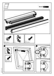
Zusammenbau der Schienen<br />
HINWEIS<br />
Der <strong>RolloPort</strong> <strong>S1</strong> wird mit drei Schienen geliefert:<br />
◆ zwei Endstücke, inkl. vormontierter Kette<br />
◆ ein Mittelteil (ohne Kette) mit zwei Verbindern<br />
Legen Sie die beiden Endstücke mit der<br />
vormontierten Kette so auf den Boden, dass<br />
die Kette möglichst gerade zwischen Ihnen<br />
verläuft.<br />
Schieben Sie die beiden beiliegenden Verbinder<br />
über das Mittelteil und legen Sie anschließend<br />
das Mittelteil in die Lücke zwischen den beiden<br />
Endstücken<br />
Führen Sie die Kette in das Mittelteil ein.<br />
Schieben Sie jeden der Verbinder über die<br />
Schnittstelle zwischen Mittelteil und dem<br />
entsprechenden Endstück.<br />
Achten Sie darauf, dass die Verbinder jeweils mittig zwischen<br />
den Fixierungsblechen der Schienenunterseite liegen.<br />
Biegen Sie zum Schluss die Fixierungsbleche<br />
mit einem kleinen Schraubendreher nach außen.<br />
Dadurch lassen sich die Verbinder nicht mehr verschieben.<br />
Antriebskette spannen<br />
Schrauben Sie die Spannmutter mit einem<br />
geeigneten Steckschlüssel (∅ 10 mm) fest.<br />
Justieren Sie die Kettenspannung, wie im<br />
Bild dargestellt.<br />
ACHtuNG: Aufgrund von Fertigungstoleranzen<br />
kann der gezeigte Einstellungsbereich von ca.<br />
37-41 mm variieren.<br />
Stellen Sie daher sicher, dass die Kette über die<br />
gesamte Schienenlänge hinweg leicht durchhängt,<br />
und somit nicht zu stramm gespannt<br />
ist. Eine zu stramm gespannte Kette kann zu<br />
Leistungsverlusten des Antriebs führen.<br />
1.<br />
2.<br />
Verbinder 1<br />
Fixierungsbleche<br />
Verbinder 2<br />
D<br />
1<br />
2<br />
3<br />
11
1.<br />
2.<br />
3.<br />
12<br />
Verbindung des Antriebsgehäuses mit der Schiene<br />
Setzen Sie zuerst den Vielzahnverbinder<br />
(5) ein.<br />
Setzen Sie die Schiene (4) mit dem innenliegenden<br />
Kettenritzel (ab Werk in der Schiene<br />
vormontiert) über den Verbinder (5).<br />
Stecken Sie zwei Haltewinkel (2) auf die<br />
Schiene (4) und schrauben Sie diese mit den<br />
beiliegenden Sechskant-Blechschrauben (6 x<br />
15 mm) am Antriebsgehäuse fest.<br />
1<br />
2<br />
3<br />
Legende<br />
1 = Sechskant Blechschrauben (6 x 15 mm)<br />
2 = Haltewinkel<br />
3 = Mikroschalter<br />
4 = Schiene<br />
5 = Vielzahnverbinder<br />
WICHtIG<br />
Achten Sie darauf, das der Mikroschalter (3) bei der<br />
Montage der Schiene nicht beschädigt wird.<br />
4<br />
5<br />
D
Befestigung des Antriebs und der Schiene<br />
(A)<br />
(C)<br />
A / B / C / D, siehe folgende Seiten<br />
Sturzmontage<br />
Die Montage sollte vorzugsweise am Sturz erfolgen, da<br />
so die auftretenden Kräfte optimal aufgenommen werden<br />
können.<br />
Deckenmontage<br />
Für die Deckenmontage sollten Sie den Sturzwinkel um<br />
90 Grad drehen und weiter innen an der Garagendecke<br />
befestigen. Dadurch kann der gesamte Schienenweg<br />
genutzt werden.<br />
HINWEIS<br />
Der Abstand zum Torblatt darf bei einer Deckenmontage<br />
max. 25 cm betragen.<br />
WICHtIG<br />
Verwenden Sie bei Garagenwänden bzw. Garagendecken<br />
aus Stein (Beton), die beiliegenden Sechskantschrauben<br />
(8 x 60) und Dübel ∅ 10 mm.<br />
(D)<br />
Sturz-<br />
montage<br />
Decken-<br />
montage<br />
(B)<br />
min. 1,5 cm<br />
max. 25 cm<br />
D<br />
13
1.<br />
2.<br />
3.<br />
1.<br />
2.<br />
3.<br />
4.<br />
14<br />
(A) Montage des Sturzwinkels (1)<br />
HINWEIS<br />
Der Sturzwinkel (1) muss mittig zum Tor montiert werden.<br />
Zeichnen Sie die Position des Sturzwinkels (1)<br />
an und bohren Sie die Montagelöcher (z.B. mit<br />
einem 10 mm Steinbohrer).<br />
Schrauben Sie den Sturzwinkel (1) mit den<br />
beiliegenden Sechskantschrauben (8 x 60<br />
mm) fest.<br />
Befestigen Sie danach die Schiene (4) mit der<br />
beiliegenden Sechskantschraube (6 x 80 mm)<br />
am Sturzwinkel (1).<br />
(B) Montage des Haltewinkels (5) am Antriebskopf (7)<br />
Schieben Sie den Haltewinkel (5) möglichst<br />
nah vor den Antriebskopf (7) auf die Schiene<br />
(4).<br />
Markieren Sie die Montagelöcher für den<br />
Haltewinkel (5).<br />
Dazu sollten Sie die gesamte Konstruktion hochheben und<br />
gegen die Decke drücken.<br />
HINWEIS<br />
Achten Sie darauf dass die Schiene (4) in Flucht zur<br />
Tormitte liegt.<br />
Bohren Sie die Montagelöcher (z.B. mit<br />
einem 10 mm Steinbohrer).<br />
Schrauben Sie zum Schluss den Haltewinkel<br />
(5) mit den beiliegenden Sechskantschrauben<br />
(8 x 60 mm) an der Garagendecke<br />
fest.<br />
4<br />
6<br />
2<br />
1<br />
3 4<br />
Legende<br />
1 = Sturzwinkel<br />
2 = Schraube (6 x 80 mm) mit<br />
Sechskantmutter<br />
3 = Sechskantschraube (8 x 60 mm)<br />
4 = Schiene<br />
7<br />
5<br />
Legende<br />
4 = Schiene<br />
5 = Haltewinkel<br />
6 = Sechskantschraube (8 x 60 mm)<br />
7 = Antriebskopf<br />
D
1.<br />
2.<br />
(C) Montage des torwinkels (8)<br />
HINWEIS<br />
Wir empfehlen Ihnen den Torwinkel (8) vorzugsweise<br />
am Torrahmen zu befestigen.<br />
Für Kunststoff- oder dünnwandige Holztore sind zusätzliche<br />
Verstrebungen nötig, um eine Beschädigung des Tores<br />
zu vermeiden. Sprechen Sie in diesem Fall mit Ihrem<br />
Torlieferanten.<br />
Verwenden Sie zur Montage des Torwinkels (8) schon<br />
vorhandene Bohrlöcher, falls möglich.<br />
Legen Sie den torwinkel (8) auf die Oberkante<br />
des Garagentores und richten Sie ihn zur tormitte<br />
(in Flucht zum Profilschlitten) aus. Zeichnen<br />
Sie anschließend die vier Befestigungslöcher<br />
auf dem torrahmen an.<br />
Schlagen Sie die Befestigungslöcher mit<br />
Hilfe des beiliegenden Schlagdorns in den<br />
torrahmen.<br />
HINWEIS<br />
Blechschrauben benötigen ausreichend Halt im<br />
Mate-rial. Prüfen Sie die Materialstärke Ihres Torrahmens.<br />
Bei ausreichender Materialstärke können Sie die<br />
Befestigungslöcher auch mit einem 4 mm Metallbohrer<br />
vorbohren, falls Sie die Löcher nicht mit dem Schlagdorn<br />
einschlagen können.<br />
8<br />
9<br />
10<br />
11<br />
12<br />
Legende<br />
8 = Torwinkel<br />
9 = Bolzen (8 x 20 mm)<br />
10 = Sechskant-Blechschraube (6 x 15 mm)<br />
11 = Sicherungssplint (2 x 20 mm)<br />
12 = Toranbinder, gekrümmt<br />
RICHtIG<br />
Befestigungsloch<br />
durch Schlagdorn<br />
Die Schraube hat<br />
ausreichend Halt<br />
FALSCH<br />
Befestigungsloch<br />
durch Bohrung<br />
Die Schraube hat<br />
keinen Halt<br />
D<br />
15
3.<br />
4.<br />
5.<br />
1.<br />
16<br />
(C) Montage des torwinkels (8)<br />
Schrauben Sie den torwinkel (8) mit den<br />
beiliegenden Sechskant-Blechschrauben<br />
(8 x 15 mm) am Rahmen fest.<br />
Befestigen Sie zum Schluss den toranbinder<br />
(12) mit dem beiliegenden Bolzen (9) am<br />
torwinkel (8).<br />
HINWEIS<br />
Ab Werk ist schon ein gerader Toranbinder vormontiert,<br />
dieser ist fest mit der Schiene verbunden.<br />
Falls Sie (je nach örtlichen Gegebenheiten) den beiliegenden,<br />
gebogenen Toranbinder verwenden wollen,<br />
müssen Sie diesen mit zwei Sechskantschrauben<br />
(8 x 20 mm) am geraden Toranbinder (12) befestigen.<br />
Sichern Sie zum Schluss den Bolzen (9) durch<br />
Aufstecken des Sicherungssplints (11) gegen<br />
Herausrutschen.<br />
(D) Montage der Mittenabhängung (13)<br />
Die Mittenabhängung (13) an geeigneter<br />
Stelle, möglichst mittig zwischen tor und<br />
Antriebskopf, montieren.<br />
Legende<br />
13 = Mittenabhängung<br />
14 = Sechskantschrauben (8 x 60 mm)<br />
13<br />
14<br />
12<br />
9<br />
D<br />
8
1.<br />
2.<br />
3.<br />
Wichtige Hinweise nach der Montage<br />
◆ Stellen Sie sicher, das die Anlage nach der Montage ord-<br />
nungsgemäß eingestellt ist, und dass der Antrieb<br />
reversiert (zurückfährt), falls das Tor einen 50 mm<br />
hohen, auf dem Boden befindlichen Gegenstand berührt<br />
(für Antriebe, die über ein Einklemmschutzsystem<br />
verfügen, dass bei Kontakt mit der Torunterkante<br />
anspricht), s. Seite 29.<br />
Hinweisschilder mit Warnhinweisen anbringen<br />
Durch unsachgemäßen Gebrauch besteht<br />
erhöhte Verletzungsgefahr.<br />
◆ Befestigen Sie die Warnaufkleber bezüglich Einklemmgefahren<br />
dauerhaft an einem gut sichtbaren Ort oder<br />
in der Nähe aller installierten Steuerungen.<br />
◆ Befestigen Sie das Etikett für manuelle Entriegelung<br />
dauerhaft neben dem Bedienungselement.<br />
◆ Bringen Sie alle Warnaufkleber, Schilder so an, dass<br />
Sie gut lesbar sind.<br />
Betriebsbereitschaft des tores herstellen<br />
Bewegen Sie das tor vorsichtig, um den<br />
Schlitten einzurasten.<br />
Stecken Sie den Netzstecker in die Steckdose<br />
und schalten Sie den Strom ein.<br />
Das Licht geht an und die Einheit gibt einen<br />
einmaligen Signalton von sich und das Display<br />
zeigt zyklisch ‘0’ an.<br />
Programmierung<br />
Damit die folgenden Einstellungen korrekt<br />
gespeichert und ausgeführt werden, müssen<br />
Sie eine abschließende Programmierung gemäß<br />
Seite 24 durchführen.<br />
◆ Stellen Sie sicher, dass der Antrieb nach der Montage<br />
die Öffnungsbewegung des Tores verhindert oder stoppt,<br />
wenn das Tor mit einer Masse von 20 kg beladen ist,<br />
die zentral an der Torunterkante befestigt ist. Dies<br />
gilt insbesondere für Antriebe, die mit einem Tor<br />
eingesetzt werden können, das Öffnungen im Torflügel<br />
mit einem Durchmesser größer 50 mm hat.<br />
D<br />
17
18<br />
Endpunkte einstellen / Oberen Endpunkt einstellen<br />
Die falsche Reihenfolge bei der Einstellung<br />
der Endpunkte führt zu Fehlfunktionen.<br />
Halten Sie unbedingt die vorgegebene Einstellreihenfolge<br />
ein.<br />
1. Drücken Sie „P“ für<br />
ca. 5 Sekunden<br />
4. Drücken Sie „+“ oder<br />
drücken Sie „-“<br />
unteren Endpunkt einstellen<br />
1. Drücken Sie „+“, in der<br />
Anzeige erscheint „2“<br />
4. Das tor fährt auf oder<br />
zu.<br />
2. Der Antrieb erzeugt<br />
einen Signalton und<br />
zeigt „1“<br />
5. Das tor fährt auf oder<br />
zu.<br />
2. Drücken Sie „P“,<br />
„2“ blinkt<br />
Korrekte Einstellreihenfolge:<br />
1. oberen Endpunkt einstellen<br />
2. unteren Endpunkt einstellen<br />
5. Ist das tor bis zur gewünschten Position<br />
heruntergefahren, drücken Sie „P“, um<br />
den unteren Endpunkt zu speichern.<br />
3. Drücken Sie „P“,<br />
„1“ blinkt<br />
6. Ist das tor bis zur gewün-<br />
schten Position hochgefah-<br />
ren, drücken Sie „P“, um<br />
den oberen Endpunkt zu<br />
speichern.<br />
3. Drücken Sie „+“ oder<br />
drücken Sie „-“<br />
D
Referenzfahrt zur Kraftmessung durchführen<br />
Während der Referenzfahrt besteht Verletzungsgefahr,<br />
da der Antrieb sehr große Kräfte<br />
entwickelt.<br />
1. Drücken Sie „+“, in der<br />
Anzeige erscheint „3“<br />
4. Drücken Sie nach dem<br />
Stopp 2 x auf „P“.<br />
7. Programmierung<br />
abschließen<br />
(s. Seite 24, Methode 1)<br />
2. Drücken Sie „P“,<br />
„3“ blinkt<br />
3. Das tor hebt sich auto-<br />
matisch.<br />
5. Das tor senkt sich. 6. Drücken Sie nach dem Stopp<br />
„P“, um die Information zu<br />
speichern.<br />
WICHtIG<br />
Mit der Einstellung der beiden Endpunkte und mit der Referenzfahrt zur Kraftmessung<br />
haben Sie die erforderlichen Grundeinstellungen zum sicheren Betrieb erfüllt.<br />
Falls Sie keinen Bedarf an weiteren Einstellungen haben, müssen Sie die Programmierung<br />
gemäß Methode 1 auf der Seite 24 abschließen um die vorangegangenen<br />
Grundeinstellungen zu übernehmen.<br />
Die folgenden individuellen Einstellungen können Sie danach jeweils einzeln oder nach<br />
allen Einstellungen mit der Methode 2 auf Seite 24 abschließen.<br />
D<br />
19
20<br />
Kraftbegrenzung bei Bedarf anpassen<br />
HINWEIS<br />
Der Antrieb ist ab Werk auf Stufe 3 eingestellt. Bei<br />
Bedarf (z.B. bei zu niedrigem Kraftniveau) können Sie<br />
die Kraftbegrenzung nachträglich anpassen.<br />
1. Drücken Sie auf „+“<br />
(evtl. mehrfach drücken)<br />
bis die „4“ angezeigt wird<br />
2. Drücken Sie „P“, in der<br />
Anzeige erscheint „7 “<br />
(Stufe 3)<br />
Ein zu niedriges Kraftniveau beeinträchtigt die<br />
torbewegung, besonders wenn die mechanische<br />
Struktur des tores nicht gut ausbalanciert ist.<br />
3. Drücken Sie „+“ oder<br />
drücken Sie „-“, um die<br />
Stufe auszuwählen.<br />
Kraftniveau<br />
niedrig hoch<br />
4. Drücken Sie „P“, um die<br />
Einstellung zu speichern<br />
Werkseinstellung<br />
5. WICHtIG<br />
Referenzfahrt zur Kraft-<br />
messung wiederholen.<br />
(s. Seite 19)<br />
6. Programmierung<br />
abschließen<br />
(s. Seite 24, Methode 1)<br />
Nach einer Neueinstellung des Kraftniveaus müssen Sie zwingend die Referenzfahrt zur Kraftmessung<br />
wiederholen und erneut die Programmierung abschließen.<br />
Während der Referenzfahrt besteht Verletzungsgefahr, da der Antrieb sehr große Kräfte entwickelt.<br />
D
Bedientaste des Handsenders einstellen<br />
HINWEIS<br />
Die Steuerung des Tores ist ab Werk auf die zweite Taste<br />
des Handsenders eingestellt.<br />
1. Drücken Sie auf „+“<br />
(evtl. mehrfach drücken)<br />
bis die „5“ angezeigt wird<br />
4. Drücken Sie taste „P“<br />
um die Einstellung zu<br />
speichern.<br />
2. Drücken Sie „P“,<br />
„2“ blinkt<br />
(2 = Werkseinstellung )<br />
5. Programmierung<br />
abschließen<br />
(s. Seite 24, Methode 2)<br />
oder weiter mit nächster<br />
Einstellung.<br />
D<br />
3. Drücken Sie „+“ oder „-“,<br />
um den gewünschten Kanal<br />
auszuwählen.<br />
1 = Taste 1<br />
2 = Taste 2<br />
21
22<br />
Alarmeinstellung<br />
Wenn der Alarm eingeschaltet ist erzeugt der<br />
Antrieb einen Signalton, wenn das tor länger als<br />
10 Minuten geöffnet ist. Der Signalton ertönt<br />
alle 10 Minuten für 30 Sekunden.<br />
1. Drücken Sie auf „+“<br />
(evtl. mehrfach drücken)<br />
bis die „6“ angezeigt wird<br />
4. Drücken Sie „P“ um die<br />
Alarmeinstellung zu<br />
speichern<br />
Automatische Schließzeiteinstellung<br />
HINWEIS<br />
Bevor sich das Tor automatisch schließt, erzeugt der<br />
Antrieb für 20 Sekunden einen Signalton. Gleichzeitig<br />
blinkt das Licht.<br />
1. Drücken Sie auf „+“<br />
(evtl. mehrfach drücken)<br />
bis die „7“ angezeigt wird<br />
2. Drücken Sie „P“, die<br />
Anzeige ist „0“<br />
(0 = Aus = Werkseinstellung)<br />
5. Programmierung<br />
abschließen<br />
(s. Seite 24, Methode 2)<br />
oder weiter mit nächster<br />
Einstellung.<br />
2. Drücken Sie „P“, die<br />
Anzeige ist „0“<br />
(0 = Aus = Werkseinstellung)<br />
Beenden des Alarmtons:<br />
Drücken Sie die Torsteuerungstaste, um das Tor vollständig<br />
zu schließen.<br />
D<br />
3. Drücken Sie „+“, die<br />
Anzeige ist „1“<br />
(1 = Ein = Die Alarmeinstellung ist<br />
eingeschaltet)<br />
Sobald sich das Tor schließt, bleibt das Licht dauerhaft<br />
eingeschaltet und der Signalton ertönt weiter.<br />
Nachdem das Tor geschlossen ist beendet der Antrieb<br />
den Signalton und das Licht bleibt für weitere 3 Minuten an.<br />
3. Drücken Sie „+“, die<br />
Anzeige ist „1“<br />
(1 = Ein = Automatische Schließzeit<br />
= 30 Sekunden)
Automatische Schließzeiteinstellung<br />
4. Drücken Sie „+“ und<br />
wählen Sie die gewünschte<br />
Schließzeit: 5 = 150 s<br />
1 = 30 s 6 = 180 s<br />
2 = 60 s 7 = 210 s<br />
3 = 90 s 8 = 240 s<br />
4 = 120 s (Maximum)<br />
2000-Zyklen-Alarmeinstellung<br />
Überprüfen Sie nach einiger Zeit des Betriebes<br />
regelmäßig, ob das tor beim Öffnen/<br />
Schließen horizontal ist und ob die Feder<br />
genügend Kraft hat, um das tor zu heben.<br />
Fügen Sie zu allen beweglichen teilen regelmäßig<br />
eine geeignete Menge Schmiermittel hinzu.<br />
1. Drücken Sie auf „+“<br />
(evtl. mehrfach drücken)<br />
bis die „8“ angezeigt wird<br />
4. Drücken Sie „P“, um die<br />
Einstellung zu speichern<br />
5. Drücken Sie „P“ um die<br />
Einstellung zu speichern<br />
2. Drücken Sie „P“, die<br />
Anzeige ist „0“<br />
(0 = Aus = Werkseinstellung)<br />
6. Programmierung<br />
abschließen<br />
(s. Seite 24, Methode 2)<br />
oder weiter mit nächster<br />
Einstellung.<br />
HINWEIS<br />
Ist diese Funktion aktiviert, wird der Antrieb nach 2000<br />
Zyklen in gewissen Abständen durch einen kurzen Pfeifton<br />
signalisieren, dass das Tor gewartet werden muss.<br />
Alarmton beenden<br />
Schalten Sie den Strom aus und wieder ein, oder<br />
drücken Sie die Taste „P“ für 5 Sekunden.<br />
3. Drücken Sie „+“, die<br />
Anzeige ist „1“<br />
(1 = Ein)<br />
5. Programmierung abschließen (s. Seite 24, Methode 2)<br />
oder weiter mit nächster Einstellung.<br />
D<br />
23
24<br />
Programmierung abschließen<br />
WICHtIG<br />
Bitte beachten, dieser abschließende Schritt muss<br />
ausgeführt werden, da die gespeicherten Informationen<br />
ansonsten verloren gehen.<br />
1. Drücken Sie nach der<br />
Referenzfahrt auf „-“<br />
(evtl. mehrfach drücken)<br />
bis „1“ angezeigt wird.<br />
HINWEIS<br />
Sie können die Programmierung wie folgt auf 2 Arten<br />
abschließen:<br />
Methode 1: Diese Methode unbedingt nach der Referenzfahrt durchführen<br />
2. Halten Sie „P“<br />
5 Sekunden lang<br />
gedrückt<br />
Methode 2: Nach allen anderen Einstellungen<br />
1. Halten Sie nach Abschluss<br />
einer beliebigen Einstellung<br />
„P“ 5 Sekunden lang<br />
gedrückt.<br />
2. „0“ wird zyklisch ange-<br />
zeigt, um die Programmie-<br />
rung abzuschließen und den<br />
Antrieb in den Ruhezustand<br />
zu versetzen.<br />
D<br />
3. „0“ wird zyklisch angezeigt,<br />
um die Programmierung ab-<br />
zuschließen und den Antrieb<br />
in den Ruhezustand zu ver-<br />
setzen.
Handsender an- und abmelden<br />
Handsender anmelden:<br />
1. Drücken Sie „S“ für<br />
1 Sekunde und lassen<br />
Sie los.<br />
2. Zur Quittierung erscheint<br />
kurz ein grüner Punkt<br />
rechts unten in der<br />
Anzeige<br />
3. Drücken Sie dreimal auf<br />
die zuvor eingestellte<br />
taste des Handsenders.<br />
HINWEIS<br />
Nach erfolgreicher Anmeldung können Sie Ihren <strong>Garagentorantrieb</strong> mit dem Handsender bedienen. Danach können Sie weitere<br />
Handsender anmelden.<br />
Handsender abmelden: Aus Sicherheitsgründen muss ein Handsender<br />
bei Verlust abgemeldet werden, damit das<br />
Garagentor nicht durch unbefugte bedient<br />
werden kann.<br />
1. „S“ drücken und<br />
gedrückt halten<br />
2. Zur Quittierung erscheint<br />
ein grüner Punkt rechts<br />
unten in der Anzeige<br />
D<br />
3. Halten Sie „S“ solange<br />
gedrückt, bis der grüne<br />
Punkt unten rechts in der<br />
Anzeige erlischt.<br />
Alle Handsender sind abgemeldet.<br />
Sie können einen neuen Handsender<br />
anmelden.<br />
25
26<br />
Anschluss elektrischer Zusatzeinrichtungen<br />
Bei allen Arbeiten an elektrischen Anlagen<br />
besteht Lebensgefahr durch Stromschlag.<br />
◆ Der Anschluss von elektrischen Zusatzeinrichtungen<br />
darf nur durch eine zugelassene Elektrofachkraft erfolgen.<br />
◆ Ziehen Sie vor dem Öffnen der Abdeckhaube immer<br />
den Netzstecker und prüfen Sie die Anlage auf Spannungsfreiheit.<br />
Herstellerfremdes Zubehör kann zu Fehlfunktionen<br />
oder zu Sachbeschädigungen führen.<br />
◆ Verwenden Sie ausschließlich Original-Zubehör.<br />
Fremdspannung an den Schraubklemmen für den<br />
externen Taster führt zum Kurzschluss und zur<br />
Zerstörung der Antriebselektronik.<br />
◆ Keine Fremdspannung an die Klemme für den externen<br />
Taster anschließen die Klemmen sind potentialfreie<br />
Kontakte.<br />
GND<br />
+ 12V<br />
2<br />
GND<br />
+ 12V<br />
COM<br />
OUT<br />
GND IR + 12V<br />
Legende<br />
1 = Hauptplatine<br />
2 = Infrarot-Lichtschranke (optional)<br />
3 = externer Schalter (optional)<br />
3<br />
Die unsachgemäße Montage von externen<br />
tastern kann die Betriebssicherheit gefährden.<br />
Montieren Sie Innentaster, Codierschalter etc. immer:<br />
◆ außerhalb der Reichweite von sich bewegenden<br />
Teilen.<br />
◆ in Sichtweite des Tores<br />
◆ mindestens in 1,5 m Höhe<br />
Ext. Schalter (Typ: NO)<br />
1<br />
GND<br />
Schlupftürkontakt<br />
ACHtuNG: Bei Anschluss Schlupftürkontakt, Brücke entfernen.<br />
Anschlussbedingungen zum Anschluss einer<br />
Infrarot-Lichtschranke:<br />
Spannung: = + 12 V<br />
Strom: = max 150 mA<br />
Typ: = NC<br />
D
1.<br />
Manueller Betrieb des tores<br />
Im Falle eines Stromausfalls:<br />
Wollen Sie das tor bei Stromausfall manuell<br />
bedienen, müssen Sie am Seil der Notentriegelung<br />
ziehen, damit diese das tor vom<br />
Antrieb entriegelt.<br />
Danach können Sie das Tor frei bewegen.<br />
Es besteht Verletzungsgefahr. Das tor kann<br />
beim Entriegeln unkontrolliert herunterfallen<br />
(z. B. wenn das tor sich nicht im Gleichgewicht<br />
befindet)<br />
◆ Schließen oder öffnen Sie nach jeder Entriegelung<br />
das Tor immer vollständig.<br />
◆ Die Notentriegelung ist nicht für den “täglichen<br />
Gebrauch” bestimmt.<br />
1.<br />
Wenn der Strom wieder da ist:<br />
Bedienen Sie den Handsender oder den<br />
HINWEIS<br />
Wandschalter.<br />
Das Einkuppeln erfolgt automatisch.<br />
D<br />
27
28<br />
Anleitung für den Anwender<br />
Hinweise für den Einsatz<br />
◆ Überprüfen Sie das Antriebssystem um festzustellen,<br />
ob es sich beim ersten Einsatz des <strong>Garagentorantrieb</strong>s<br />
leicht bewegt.<br />
◆ Überprüfen Sie nach einiger Zeit im Gebrauch regelmäßig,<br />
ob das Tor beim Öffnen/Schließen horizontal bleibt<br />
und ob die Feder genügend Kraft hat, um das Tor zu<br />
heben. Fügen Sie zu allen beweglichen Teilen regelmäßig<br />
eine geeignete Menge Schmiermittel hinzu.<br />
◆ Im Falle eines Stromausfalls können Sie die Notentriegelung<br />
ziehen und das Tor von Hand frei bewegen.<br />
Wenn der Strom wieder zur Verfügung steht, können<br />
Sie den Handsender oder die Wandkonsole bedienen,<br />
die Notentriegelung rastet auto matisch ein.<br />
Das Tor kann danach wieder mit dem Handsender oder<br />
der Wandkonsole bedient werden.<br />
1. Im Falle eines Strom-<br />
ausfalls stoppt das tor<br />
seine Bewegung.<br />
Normalbetrieb<br />
◆ Fernbedienung<br />
Durch das Drücken der zuvor eingestellten Taste des<br />
Handsenders kann das Tor geöffnet, geschlossen oder<br />
angehalten werden.<br />
◆ Handbedienung<br />
Im Falle eines Stromausfalls kann das Öffnen oder<br />
Schließen des Tors von Hand erfolgen, sobald der<br />
Antrieb entkoppelt wurde (s. Seite 27).<br />
2. Drücken Sie sobald der<br />
Strom wieder zur Ver-<br />
fügung steht, die zuvor<br />
eingestellte taste (s.<br />
Seite 21) des Hand-<br />
senders, das tor öffnet<br />
sich.<br />
3. Entsprechend dem Pro-<br />
grammspeicher hebt sich<br />
das tor bis zum oberen<br />
Endpunkt und bleibt dann<br />
stehen.<br />
D
1.<br />
2.<br />
3.<br />
4.<br />
5.<br />
6.<br />
Wartung<br />
Durch defekte toranlagen bzw. Sicherheitseinrichtungen<br />
besteht Verletzungsgefahr.<br />
Zu Ihrer Sicherheit sollten Sie die empfohlenen<br />
Wartungsintervalle für Ihre toranlage<br />
inkl. aller Sicherheitseinrichtungen einhalten.<br />
Wartungsintervall:<br />
Lassen Sie die toranlage vor der ersten Inbetriebnahme,<br />
je nach Bedarf jedoch mindestens<br />
einmal jährlich von einem Fachbetrieb<br />
prüfen.<br />
Regelmäßige Prüfungen der Verschleißteile<br />
Es besteht Verletzungsgefahr durch defekte<br />
bzw. verschlissene Bauteile.<br />
Prüfen Sie daher die Anlage regelmäßig auf Anzeichen<br />
von Verschleiß, Beschädigung oder auf mangelhafte<br />
Balance des Tores.<br />
Benutzen Sie das Tor auf keinen Fall, wenn Reparaturoder<br />
Einstellarbeiten durchgeführt werden müssen, da ein<br />
Fehler in der Anlage oder ein falsch ausbalanciertes Tor<br />
Verletzungen verursachen kann.<br />
Monatliche Prüfung der Hinderniserkennung (Kraftbegrenzung)<br />
Fahren Sie das tor in die Endstellung auf.<br />
Legen Sie einen 50 mm hohen Gegenstand,<br />
z. B. einen Holzklotz, in die Laufrichtung<br />
des tores.<br />
Schließen Sie das tor durch Betätigen des<br />
Handsenders.<br />
Stößt das tor bei Schließen oder Öffnen<br />
gegen ein Hindernis, stoppt der Antrieb automatisch<br />
und öffnet das Garagentor vollständig.<br />
Entfernen Sie anschließend das Hindernis.<br />
Nach der Beseitigung des Hindernisses<br />
können Sie den <strong>Garagentorantrieb</strong> wieder<br />
normal bedienen.<br />
Prüfen Sie:<br />
◆ Alle Schraubenverbindungen auf festen Sitz<br />
◆ Kabel auf Beschädigung<br />
◆ Federn und Befestigungsteile<br />
Es besteht Verletzungsgefahr durch die<br />
sehr stark gespannten torfedern.<br />
◆ Tauschen Sie niemals selbst die Torfedern aus.<br />
◆ Lassen Sie alle Arbeiten an der Tormechanik und<br />
den Federn von einem Fachmann durchführen.<br />
Einen ca. 50 mm Holzklotz in die Laufrichtung des<br />
Tores legen.<br />
Die Justierung falls notwendig korrigieren<br />
und erneut überprüfen, da eine unkorrekte<br />
Justierung eine Gefährdung darstellen kann.<br />
D<br />
29
i<br />
30<br />
technische Spezifikationen<br />
Modell und empfohlene Verwendung<br />
Artikel-Nr. Spannung (V) torgröße (m2 ) Zulässige umgebungstemperatur (°C)<br />
4601 65 71<br />
4602 65 71<br />
220 – 240 ≤ 10 –20...+40<br />
Führungsschiene und verfügbare Größen<br />
Artikel-Nr. Gesamtlänge Bewegungshub Hubhöhe<br />
4601 65 71 3020 mm 2560 mm < 2240 mm<br />
4602 65 71 3620 mm 3160 mm < 2840 mm<br />
technische Daten<br />
Leistung: 100 W<br />
Standby-Modus: < 1 W<br />
Zugkraft: 650 N<br />
Versorgungsspannung: 230 V / 50 Hz<br />
Motor: 24 V (DC) Gleichstrom<br />
Licht : Power LED mit Zeitbegrenzung<br />
Torlaufgeschwindigkeit:<br />
Sicherungsmodell:<br />
11 cm/Sekunde<br />
- Antriebssicherung 1: 2,5 A<br />
- Lichtsicherung 2: 2,5 A<br />
Sendefrequenz und -reichweite: 433 MHz/offenes Gelände 50 m<br />
Antrieb: Kette<br />
Schutzmethode: Nur in trockenen Räumen verwenden<br />
Zulässige Garagentormaße<br />
Zulässige Torblattfläche: 10,5 m 2 (für leichtgängige Schwing- und Sektionaltore)<br />
Max. Füllungsgewicht<br />
für Schwingtore: 7 kg/m 2<br />
D
i<br />
i<br />
Fehlerbehebung<br />
Fehler<br />
Der Antrieb funktioniert nicht.<br />
Der Handsender kann den Antrieb<br />
nicht bedienen.<br />
Die Reichweite des Handsenders ist<br />
zu gering.<br />
Die Kette bewegt sich, aber das Tor nicht.<br />
Im Betrieb ist ein reibendes Geräusch<br />
zu hören.<br />
Die Kette hängt durch und ist laut.<br />
CE-Zeichen und EG-Konformität<br />
ursachen<br />
1. Der Stecker ist nicht sicher eingesteckt.<br />
2. Die Sicherung hat ausgelöst.<br />
1. Der Handsender wurde eventuell<br />
falsch oder gar nicht angemeldet<br />
2. Die Batterie ist leer.<br />
Die Batterie ist möglicherweise leer.<br />
Die Notentriegelung ist möglicherweise<br />
ausgelöst.<br />
Mangel an Schmiermittel zwischen<br />
Schiene und Kettenschlitten nach langer<br />
Bedienzeit.<br />
Die Kette ist lose aufgrund langen<br />
Gebrauchs ohne Schmiermittel zwischen<br />
der Schiene und dem Kettenschlitten.<br />
D<br />
Lösung<br />
1. Netzstecker in Steckdose stecken.<br />
2. Ursache von einem Techniker prüfen<br />
lassen, danach die Sicherung<br />
wieder einschalten.<br />
1. Melden Sie den Handsender neu<br />
an, siehe Seite 25.<br />
2. Setzen Sie eine neue Batterie ein.<br />
Ersetzen Sie sie durch eine Neue vom<br />
gleichen Modell.<br />
Bedienen Sie den Antrieb, bis die<br />
Notentriegelung automatisch wieder<br />
einrastet.<br />
Fügen Sie an der Position zwischen Schiene<br />
und Kettenschlitten ein geeignetes<br />
Schmiermittel ein.<br />
Spannen Sie die Kette wie auf Seite 11<br />
beschrieben und tragen Sie ein geeignetes<br />
Schmiermittel auf die Kette auf.<br />
Die <strong>Garagentorantrieb</strong>e der Serie <strong>RolloPort</strong> <strong>S1</strong> (Artikel-Nr. 4601 65 71 / 4602 65 71) inklusive Handsender, erfüllen die<br />
Anforderungen der geltenden europäischen und nationalen Richtlinien.<br />
2006/95/EG Niederspannungsrichtlinie<br />
2006/42/EG Maschinenrichtlinie<br />
2004/108/EG EMV Richtlinie<br />
1999/5/EG R&ttE Richtlinie<br />
Die Konformität wurde nachgewiesen. Die entsprechenden Erklärungen und Unterlagen sind beim Hersteller hinterlegt.<br />
<strong>RADEMACHER</strong> Geräte-Elektronik GmbH & Co. KG<br />
Buschkamp 7<br />
46414 Rhede<br />
Deutschland<br />
31
i<br />
32<br />
Dear Customers...<br />
...with your purchase of this garage door operator,<br />
you have decided for a quality product manufactured<br />
by <strong>RADEMACHER</strong>. We would like to thank you for your<br />
confidence.<br />
i these instructions...<br />
i Key to Symbols<br />
…describe how to install, connect<br />
and operate the <strong>RolloPort</strong> <strong>S1</strong>.<br />
Before you begin work, please read these instructions all the<br />
way through and follow all of the safety instructions.<br />
Please save these instructions and give them to any future<br />
owners.<br />
For damage resulting from noncompliance with these<br />
instructions and safety instructions, the guarantee is void.<br />
We assume no liability for any consequent damage.<br />
STOP<br />
The new <strong>RADEMACHER</strong><br />
garage door operator<br />
has been designed in an<br />
effort to the greatest possible<br />
ease of operation. With<br />
uncompromising quality requirements,<br />
after extensive<br />
test series, we are proud<br />
to present this innovative<br />
product to you.<br />
All of our highly qualified<br />
staff at <strong>RADEMACHER</strong><br />
stand behind this product.<br />
EN<br />
Danger of fatal electric shock<br />
This sign warns of danger when working on electrical<br />
connections, components etc. It requires that safety<br />
precautions be taken to protect the health and life of<br />
the person concerned.<br />
this concerns your safety<br />
Please pay particular attention to and carefully follow<br />
all instructions with this symbol.<br />
this symbol advises of malpractices that can<br />
cause damage to people and property.<br />
NOtE/IMPORtANt/CAutION<br />
This is to draw your attention to information which<br />
works is important to ensure trouble-free operation.
1.<br />
2.<br />
3.<br />
4.<br />
5.<br />
6.<br />
7.<br />
8.<br />
9.<br />
i Supply package<br />
D Betriebs- und Montageanleitung für den <strong>Garagentorantrieb</strong> <strong>RolloPort</strong> <strong>S1</strong><br />
EN Operating and Installation Instructions for <strong>RolloPort</strong> <strong>S1</strong> Garage Door Operator<br />
Artikel-Nr. / Item no: 4601 65 71 / 4602 65 71<br />
Contents<br />
General view .........................................................3<br />
Supply package.....................................................33<br />
Functional description ............................................36<br />
Important installation instructions ...........................37<br />
Assembly of the rails .............................................40<br />
Connecting the door operator housing to the rail ....41<br />
Attachment of the door operator and the rail ...........42<br />
Programming .......................................................46<br />
Registering and de-registering hand transmitters ......54<br />
Connection of additional electrical equipment ..........55<br />
Maintenance .......................................................58<br />
Technical specification ...........................................59<br />
CE Mark und EC Conformity ......................................60<br />
Warranty conditions ..............................................61<br />
Inhalt<br />
Gesamtansicht ........................................................3<br />
Lieferumfang .........................................................4<br />
Funktionsbeschreibung ............................................7<br />
Wichtige Montagehinweise ......................................8<br />
Zusammenbau der Schienen ..................................11<br />
Verbindung des Antriebsgehäuses mit der Schiene ...12<br />
Befestigung des Antriebs und der Schiene ...............13<br />
Programmierung ....................................................17<br />
Handsender an- und abmelden ...............................25<br />
Anschluss elektrischer Zusatzeinrichtungen ..............26<br />
Wartung .......................................................29<br />
Technische Spezifikationen ....................................30<br />
CE-Zeichen und EG-Konformität..................................31<br />
Garantiebedingungen .............................................61<br />
VBD 542-1 (11.12)<br />
10.<br />
11.<br />
12.<br />
13.<br />
14.<br />
15.<br />
16.<br />
17.<br />
18.<br />
19.<br />
1.<br />
2.<br />
3.<br />
4.<br />
5.<br />
6.<br />
7.<br />
8.<br />
9.<br />
10.<br />
11.<br />
12.<br />
13.<br />
14.<br />
15.<br />
16.<br />
17.<br />
18.<br />
19.<br />
EN<br />
Please compare the contents of the package<br />
with the content description on the<br />
packaging:<br />
1 x Drive<br />
1 x Operating instructions<br />
2 x Hand transmitter FR1<br />
1 x Door connector, bent<br />
2 x Middle support clip<br />
3 x Fixing bracket<br />
1 x Header bracket<br />
1 x Door bracket<br />
1 x Connector<br />
8 x Self-tapping hexagon screw (6 x 15 mm)<br />
1 x Screw (6 x 80 mm) with hexagon nut<br />
1 x Bolt (8 x 20 mm)<br />
1 x Securing bolt (2 x 20 mm)<br />
4 x Screw (8 x 20 mm) with hexagon nut<br />
and plain washer<br />
6 x Wall plug (10 mm)<br />
6 x Hexagon head screw (8 x 60 mm)<br />
1 x Spike<br />
2 x Mounting strap<br />
3 x Rails + 2 x Connectors<br />
33
i<br />
i<br />
i<br />
i<br />
34<br />
Correct use<br />
use the garage door operator only:<br />
◆ to open and close garage doors<br />
◆ for private use<br />
◆ according to the instructions and safety<br />
regulations in this manual<br />
Any other use shall be regarded as non-compliant<br />
with the intended use.<br />
Operating conditions<br />
◆ Only operate the garage door operator in dry rooms.<br />
◆ The garage door must be able to be opened and<br />
closed easily by hand and must not jam.<br />
Improper use<br />
Incorrectly performed structural alterations<br />
result in the risk of injury.<br />
Do not carry out any structural alterations to the door<br />
operator, the garage door or any existing safety equipment<br />
which deviate from the measures described in this<br />
manual. Such alterations endanger the operating safety.<br />
the garage door operator must not be used:<br />
◆ in commercial establishments<br />
◆ to operate other objects<br />
◆ in continuous operation<br />
Admissible garage door types<br />
◆ swing out standard up-and-over doors<br />
◆ sectional doors<br />
The doors must move smoothly and comply with the regulations<br />
of the following standards: EN 12453 and EN 12604.<br />
EN<br />
Correct use of the hand transmitter<br />
The remote control via hand transmitter is only admissible<br />
for appliances and equipment in which radio<br />
interference in the transmitter or receiver does not<br />
present a hazard for persons, animals or property or<br />
for which the risk is covered by other safety equipment.<br />
Comply with all maintenance intervals<br />
Proper use also includes the regular inspection of the<br />
door and its safety equipment.<br />
◆ Ensure that the overhead ceiling tracks are always<br />
free of grease and dirt. Dirty overhead ceiling tracks<br />
hinder proper operation.<br />
◆ A 220 - 240 V/50 - 60 Hz power supply must be<br />
available at the place of installation.<br />
Incorrect installation results in the risk of<br />
injury.<br />
Movable parts of the garage door must not extend into<br />
public footpaths or cycle paths.<br />
The manufacturer is not liable for damage which occurs<br />
due to incorrect or non-compliant use (see warranty<br />
conditions).<br />
up-and-over doors Ceiling sectional doors
i Inadmissible types of garage door<br />
i<br />
Doors which require tilting and rotating<br />
movements may not be operated with the<br />
type <strong>S1</strong> garage door operator.<br />
General safety instructions<br />
Important safety instructions<br />
CAutION<br />
For your safety and the safety of others, it is<br />
essential that you follow these instructions<br />
carefully.<br />
Keep these instructions on file.<br />
All work performed on electrical equipment<br />
is associated with a risk of electric shock<br />
and electrocution.<br />
◆ Have all work on electrical equipment and on the<br />
door operator carried out by a qualified electrician.<br />
◆ Before commencing any work on the door or the<br />
door operator, unplug the mains cable from the<br />
electrical socket.<br />
the use of defective devices can put people<br />
and property at risk.<br />
◆ Never use faulty or damaged devices.<br />
◆ Please make sure that the door operator and mains<br />
cable are free from damage.<br />
◆ Please notify our customer service department (see<br />
page 62) of any faults or damage to the device.<br />
Faulty doors can result in injuries.<br />
◆ The operation of the door must not be hindered by<br />
badly adjusted springs or poorly functioning door<br />
installation or door constructions.<br />
◆ There is a risk of injury due to the tightly stretched<br />
door springs. Never replace the door springs yourself.<br />
◆ Have all work on the door mechanics and the springs<br />
carried out by a qualified person.<br />
Power-driven doors entail the risk of crushing<br />
and shearing at the closing edge.<br />
◆ Ensure that during operation there are no persons<br />
in the swivelling range of the garage door.<br />
Non swinging out<br />
retractable up-andover<br />
door<br />
EN<br />
Improper use increases the risk of injury.<br />
◆ Never reach into the moving door or into moving<br />
parts.<br />
◆ Instruct all persons who operate the garage door in<br />
the safe use of the equipment.<br />
◆ Do not allow anyone to go through under the moving<br />
door.<br />
◆ Keep children away when the door is moving.<br />
◆ Do not allow children to play with the door or with<br />
the hand transmitter.<br />
◆ Please store the hand transmitter in such a way that<br />
it cannot unintentionally be operated by, e.g. playing<br />
children.<br />
◆ Drive in and out of the garage only when the door<br />
is fully open and stationary.<br />
◆ This appliance is not intended for use by persons (including<br />
children) with reduced physical, sensory or mental<br />
capabilities, or lack of experience and knowledge,<br />
unless they have been given supervision or instruction<br />
concerning use of the appliance by a person responsible<br />
for their safety.<br />
In the case of defective or inoperable safety<br />
equipment there is a danger of injury or<br />
damage to property.<br />
◆ Before first operation and thereafter one a month<br />
inspect the correct functioning of the safety equipment<br />
(e.g. the power limiter).<br />
◆ Never switch off the safety equipment.<br />
◆ Keep the door limit stop on the ground free of ice,<br />
snow, dirt and stones.<br />
35
i<br />
i<br />
36<br />
Functional description<br />
Intelligent microcomputer<br />
Intelligent, computerized, exact positioning of travel,<br />
prompt power determination, reverses if obstructions<br />
are met.<br />
Door operator<br />
Low noise, soft start and soft stop protect the motor<br />
and ensure a long service life.<br />
Self diagnosis<br />
Operational mode and digital menu shown on the<br />
display, self diagnosis.(L-Normal, F-Interrupted, H-Fail<br />
In Reading, A-Infrared Ray Interrupted)<br />
Cryptoguard<br />
Rolling code technology provides billions of code combinations<br />
and makes every remote control a unique one<br />
that protects against unauthorized access.<br />
Alarm unit<br />
The alarm sounds when the door is left open for longer<br />
than 10 minutes. The alarm stops when the door is<br />
closed again (refer to „Alarm setting“ on page 51).<br />
Functional description / Recognition of obstructions<br />
The door operator has an automatic obstacle-recognition<br />
system (through internal monitoring of power).<br />
If the door encounters an obstruction when closing or<br />
opening, the door operator stops the door automatically<br />
and moves it in the opposite direction until it reaches<br />
the corresponding limit.<br />
After removing the obstruction you can operate the<br />
garage door operator normally again.<br />
EN<br />
Emergency release device<br />
The door can be manually operated by pulling down<br />
on the emergency release cable in the case of power<br />
failure.<br />
Automatic closing function<br />
The automatic closing time of the door can be set from<br />
30 to 240 seconds (refer to page 51/52).<br />
2000 cycle alarm<br />
When the operator has run 2000 cycles, it will beep<br />
to remind the user to service the mechanical system<br />
(refer to page 52).<br />
Lighting<br />
The <strong>S1</strong> garage door operator has internal lighting which<br />
is switched on after each switching impulse and goes<br />
off again automatically after 3 minutes.<br />
Additional connecting options for external<br />
accessories and safety unit<br />
In addition you can connect an external switch and an<br />
infrared photoelectric barrier (refer to page 55).
i Functional description/emergency release<br />
In the event of a power cut, the door can be operated<br />
manually by pulling the emergency release cable.<br />
there is a risk of injury. the door can fall uncontrollably<br />
when it is released (e.g. if springs<br />
are weak or broken, or if the door is not properly<br />
balanced).<br />
◆ Always close or open the door fully after each release.<br />
◆ The emergency release is not intended for<br />
„everyday use“.<br />
Important installation instructions<br />
CAutION<br />
Important instructions for a safe installation.<br />
Follow all installation instructions carefully.<br />
An incorrect installation can lead to serious<br />
injuries.<br />
Before installation check...:<br />
◆ ...whether your door operator is suitable for the type<br />
of garage door and the garage door height.<br />
◆ ...that the door is in a perfect mechanical state. The<br />
door must be smooth running and be balanced.<br />
Check whether it opens and closes properly;<br />
Open the door approx. 1 metre and let go. A<br />
balanced door should now remain in this position.<br />
If not, have your door adjusted by a specialist<br />
company.<br />
◆ The door operation must not be hindered by incorrectly<br />
adjusted springs or by incorrectly functioning<br />
door suspensions or door constructions.<br />
Before installing the drive...,<br />
◆ ....remove all unnecessary ropes or chains and disable<br />
any equipment, such as locks, not needed for powered<br />
operation.<br />
STOP<br />
EN<br />
During installation there is a danger of injury<br />
due to the unsecured door falling suddenly.<br />
◆ During the installation work, ensure that there are<br />
no persons in the swivelling area of the garage door.<br />
Faulty installation can result in serious accidents<br />
and injuries.<br />
◆ Fit the actuator for the emergency release at a height<br />
of less than 1.8 metres.<br />
◆ Use only the enclosed mounting materials and only<br />
original spare parts and original accessories.<br />
◆ Any existing door locking devices already fitted to<br />
the door may hinder the correct functioning of the<br />
door and must therefore be removed.<br />
◆ Poor lighting hinders the installation work and can<br />
result in injuries. Ensure that there is adequate<br />
lighting during installation work.<br />
◆ It is possible that during the installation work, you<br />
may not be able to open the door for a short period<br />
of time.<br />
◆ Drive is not to be used with doors having openings exceeding<br />
10 mm in diameter or having edges or protruding<br />
parts a person could grip or stand on.<br />
37
1.<br />
38<br />
Required tools<br />
You require the following tools<br />
Remove the door locks<br />
Remove all vertical and horizontal door locks<br />
and catches.<br />
IMPORtANt!<br />
Keep the „old“ door locks in a<br />
safe place.<br />
In the event that you should remove the garage door<br />
operator, you will have to fit these again in order to<br />
restore the original state of the door.<br />
EN
1.<br />
2.<br />
3.<br />
take measurements<br />
Measure up and mark the centre of the door<br />
Mark the centre of the door, as shown, on the upper<br />
edge of the door, on the door lintel and on the garage<br />
ceiling.<br />
Determine the distance between the top edge<br />
of the door and the ceiling<br />
Close the door slowly and measure the distance between<br />
the top edge of the door and the ceiling.<br />
NOtE<br />
the minimum distance should be 6 cm.<br />
Installation advice for fitting to sectional<br />
doors<br />
If the garage door operator is used for a sectional door,<br />
then the guide roller of the upper door segment must be<br />
in the bend of the guide rail when the door is closed.<br />
up-and-down<br />
door<br />
sectional<br />
door<br />
min. 6 cm<br />
✗<br />
min. 6 cm<br />
Right Wrong<br />
EN<br />
39
1.<br />
2.<br />
3.<br />
4.<br />
5.<br />
1.<br />
2.<br />
40<br />
Assembly of the rails<br />
NOtE<br />
The <strong>RolloPort</strong> <strong>S1</strong> is supplied with three rails:<br />
◆ two end pieces, including a pre-assembled chain<br />
◆ a middle piece (without a chain) with two connectors<br />
Lay the two end pieces with the preassembled<br />
chain on the ground, with the<br />
chain lying as straight as possible be-tween<br />
the two end pieces.<br />
Push the two enclosed connectors onto the<br />
middle piece and then lay the middle piece in<br />
the gap between the two end pieces.<br />
Insert the chain into the middle piece.<br />
Push each of the connectors onto the join<br />
between the middle piece and each of the<br />
end pieces.<br />
Please ensure that each of the connectors lies in the<br />
centre between the fixing plates of the rail underside.<br />
Finally, bend the fixing plates outwards with<br />
a small screwdriver.<br />
As a result, the connectors can no longer be moved.<br />
tension the drive chain<br />
Screw the clamping nut tight with a suitable<br />
socket key (∅ 10 mm).<br />
Adjust the tension of the chain as shown in<br />
the picture.<br />
AttENtION: Due to manufactoring tolerances,<br />
the shown range of approx. 37-41 mm can<br />
vary. Make shure that the chain sags a little<br />
on the full length of the rail, so that it is not<br />
streched too tight. Otherwise it can result in a<br />
loss of power the drive.<br />
1.<br />
2.<br />
Connector 1<br />
Fixing plates<br />
Connector 2<br />
EN<br />
1<br />
2<br />
3
1.<br />
2.<br />
3.<br />
Connect the door operator housing to the rail<br />
First of all insert the connector (5).<br />
Place the rail (4) with the inboard chain<br />
sprocket (supplied pre-assembled in the rail)<br />
over the connector (5).<br />
Place the two fixing brackets (2) over the<br />
rail (4) and screw these firmly onto the<br />
door operator housing with the enclosed<br />
self-tapping hexagon screws (6 x 15 mm).<br />
1<br />
2<br />
3<br />
Key<br />
1 = Self-tapping hexagon screw (6 x 15 mm)<br />
2 = Fixing brackets<br />
3 = Microswitch<br />
4 = Rail<br />
5 = Connector<br />
4<br />
5<br />
EN<br />
IMPORtANt<br />
Ensure that the microswitch (3) is not damaged when<br />
mounting the rail.<br />
41
42<br />
Attachment of the door operator and the rail<br />
(A)<br />
(C)<br />
A / B / C / D refer to the following pages<br />
Installation on the lintel<br />
The installation should preferably be on the lintel, as<br />
this means that the forces encountered can best be<br />
absorbed.<br />
Installation on the ceiling<br />
For installation on the ceiling, you should rotate the<br />
header bracket by 90 degrees and fix it to the ceiling<br />
further inward. The full rail length can then be used<br />
as a result.<br />
NOtE<br />
When fitted to the ceiling, the distance to the door leaf<br />
must be a maximum of 25 cm.<br />
IMPORtANt<br />
In the case of garage walls or garage ceilings made<br />
of stone (concrete), use the enclosed hexagon screws<br />
(8 x 60) and wall plugs ∅ 10 mm.<br />
(D)<br />
Installation<br />
on the<br />
lintel<br />
Installation<br />
on the<br />
ceiling<br />
(B)<br />
min. 1,5 cm<br />
max. 25 cm<br />
EN
1.<br />
2.<br />
3.<br />
1.<br />
2.<br />
3.<br />
4.<br />
(A) Installation of the header bracket (1)<br />
NOtE<br />
The header bracket (1) must be aligned with the midpoint<br />
of the door.<br />
Mark out the position of the header bracket<br />
(1) and drill the mounting holes (e.g. with a<br />
10 mm masonry drill bit).<br />
Screw the header bracket (1) tight with the<br />
enclosed hexagon screws (8 x 60 mm).<br />
then fix the rail (4) with the enclosed<br />
hexagon screw (6 x 80 mm) to the header<br />
bracket (1).<br />
(B) Installation of the fixing bracket (5) at the door operator head (7)<br />
Push the fixing bracket (5) onto the rail (4), as<br />
close to the door operator head (7) as possible.<br />
Mark the mounting holes for the fixing<br />
bracket (5).<br />
In order to do so, lift the entire construction and push<br />
it against the ceiling.<br />
NOtE<br />
Ensure that the rail (4) is aligned with the centre of<br />
the door.<br />
Drill the mounting holes (e.g. with a 10 mm<br />
masonry drill bit).<br />
Finally screw the fixing bracket (5) to the garage<br />
ceiling with the enclosed hexagon screws<br />
(8 x 60 mm).<br />
4<br />
6<br />
2<br />
1<br />
3 4<br />
Key<br />
1 = Header bracket<br />
2 = Screw (6 x 80 mm) with hexagon nut<br />
3 = Hexagon screw (8 x 60 mm)<br />
4 = Rail<br />
7<br />
5<br />
Key<br />
4 = Rail<br />
5 = Fixing bracket<br />
6 = Hexagon screw (8 x 60 mm)<br />
7 = Door operator head<br />
EN<br />
43
1.<br />
2.<br />
44<br />
(C) Installation of the door bracket (8)<br />
NOtE<br />
We recommend fixing the door bracket (8) to the door<br />
frame if possible.<br />
For plastic or thin-walled wooden doors, additional crossbeams<br />
are necessary in order to avoid damaging the door.<br />
In this case, consult your door supplier.<br />
Use existing drillholes, if possible, to mount the door<br />
bracket (8).<br />
Place the door bracket (8) on the top edge<br />
of the garage door and align it with the centre<br />
of the door (in a line with the profile slide).<br />
Next, mark out the four fixing holes on the<br />
door frame.<br />
Punch in the fixing holes in the door frame<br />
with the aid of the enclosed spike<br />
NOtE<br />
Self-tapping screws need sufficient hold in the material.<br />
Check the thickness of your door frame. If it is<br />
sufficiently thick you can also pre-drill the fixing holes<br />
with a 4 mm metal drill bit if you are not able to punch<br />
in the holes with the spike.<br />
8<br />
9<br />
10<br />
RIGHt<br />
Fixing hole made<br />
using spike<br />
the screw has<br />
sufficient hold<br />
11<br />
WRONG<br />
12<br />
Fixing hole made<br />
by drilling<br />
the screw does not<br />
have sufficient hold<br />
EN<br />
Key<br />
8 = Door bracket<br />
9 = Bolt (8 x 20 mm)<br />
10 = Self-tapping hexagon screw (6 x 15 mm)<br />
11 = Securing bolt (2 x 20 mm)<br />
12 = Door connector, bent
3.<br />
4.<br />
5.<br />
1.<br />
(C) Installation of the door bracket (8)<br />
Screw the door bracket (8) tight with<br />
the enclosed self-tapping hexagon screws<br />
(8 x 15 mm).<br />
Finally, fix the door connector (12) to the<br />
door bracket (8) with the enclosed bolt (9).<br />
NOtE<br />
A straight door connector is supplied pre-assembled,<br />
and this is permanently fixed to the rail.<br />
If you wish to use the bent door connector enclosed<br />
(depending upon your door particular configuration), you<br />
must attach this with two hexagon screws (8 x 20) to the<br />
straight door connector (12).<br />
Finally, secure the bolt (9) by attaching the securing<br />
bolt (11) to prevent it from slipping out.<br />
(B) Installation of the middle support clip (13)<br />
Fit the middle support (13) clip at a suitable<br />
place, as near as possible to the middle point<br />
between the door and the door operator head.<br />
Key<br />
13 = Middle support clip<br />
14 = Hexagon screws (8 x 60 mm)<br />
13<br />
14<br />
12<br />
9<br />
EN<br />
8<br />
45
1.<br />
2.<br />
3.<br />
46<br />
Important notes after installation<br />
◆ After installation, ensure that the mechanism is properly<br />
adjusted and that the drive reverses when the door<br />
contacts a 50 mm high object placed on the floor<br />
(for drives incorporating an entrapment protection<br />
system depending on contact with the bottom edge of<br />
the door), s. page 58.<br />
Attach safety notices with warning messages<br />
Improper use results in an increased risk of<br />
injury.<br />
◆ Permanently fix the labels warning against entrapment<br />
in a prominent place or near any fixed controls.<br />
◆ Permanently fix the label concerning the manual release<br />
adjacent to its actuating member.<br />
◆ Attach all labels so that they are clearly legible.<br />
Establish operational readiness of the door<br />
Move the door carefully, in order to engage<br />
the profile slide.<br />
Plug the mains plug into the socket and<br />
switch on the electricity.<br />
the light goes on and the unit gives a single<br />
beep and the display shows ‘0’ at regular<br />
intervals.<br />
Programming<br />
In order that the following settings are correctly<br />
stored and executed, you must carry<br />
out a final programming procedure according<br />
to page 53.<br />
EN<br />
◆ After installation, ensure that the drive prevents or stops<br />
the opening movement when the door is loaded with<br />
a mass of 20 kg, fixed centrally on the bottom edge<br />
of the door. This applies especially to drives which can<br />
be used with a door that has openings in the door leaf<br />
larger than 50 mm in diameter.
Setting limits / setting the upper limit<br />
Carrying out the instructions in the wrong<br />
order when setting the limits will result in<br />
malfunctions. Be sure to keep to the setting<br />
order specified.<br />
1. Press „P“ for<br />
approx. 5 seconds<br />
4. Press „+“ or press „-“<br />
Setting the lower limit<br />
1. Press „+“, the<br />
display shows „2“<br />
4. the door opens<br />
or closes.<br />
2. the door operator<br />
beeps and shows „1“<br />
5. the door opens<br />
or closes.<br />
2. Press „P“,<br />
„2“ flashes<br />
Correct setting order:<br />
1. Set upper limit<br />
2. Set lower limit<br />
5. If the door has moved downwards<br />
to the required position, press „P“<br />
to store the lower limit.<br />
3. Press „P“,<br />
„1“ flashes<br />
EN<br />
6. If the door has moved up-<br />
wards to the required po-<br />
sition, press „P“ to store<br />
the upper limit.<br />
3. Press „+“ or press „-“<br />
47
48<br />
Carry out reference run for power measurement<br />
During the reference run there is a risk<br />
of injury, as the door operator develops<br />
extremely strong forces.<br />
1. Press „+“, the<br />
display shows „3“<br />
4. After it has stopped,<br />
press the „P“ button<br />
twice.<br />
7. Conclude the pro-<br />
gramming (refer to<br />
page 53, method 1)<br />
2. Press „P“,<br />
„3“ flashes<br />
3. the door goes up<br />
automatically.<br />
5. the door goes down. 6. After it has stopped, press<br />
„P“, to store the informa-<br />
tion.<br />
EN<br />
IMPORtANt<br />
Once you have set the two limits and the reference run for power measurement,<br />
you have fulfilled the basic settings required for safe operation.<br />
If you do not require any further settings, you must conclude programming as<br />
specified in method 1 on page 53, in order to adopt the basic settings you have<br />
just programmed. -<br />
After this, you can conclude the following individual settings, either singly or after<br />
all the settings have been programmed, using method 2 on page 53.
Adjust power limiting as required<br />
NOtE<br />
The door operator is preset to stage 3 by the supplier.<br />
If required (e.g. if the power level is too low) you can<br />
subsequently adjust the power limiting setting.<br />
1. Press „+“ (if necessary<br />
press several times) until<br />
„4“ is displayed.<br />
2. Press „P“, the display<br />
shows „7“ (stage 3)<br />
EN<br />
If the power level is too low, the door<br />
movement will be impaired, particularly if<br />
the mechanical structure of the door is not<br />
well balanced.<br />
3. Press „+“ or press „-“<br />
to select the stage.<br />
Power level<br />
Low High<br />
4. Press „P“, in order<br />
to store the setting<br />
Factory setting<br />
5. IMPORtANt<br />
Repeat reference run<br />
for power limiting<br />
(refer to page 48)<br />
6. Conclude programming<br />
(refer to page 53,<br />
method 1)<br />
After a resetting of the power level, it is absolutely necessary to repeat the reference run for power<br />
limiting and to conclude the programming again.<br />
During the reference run there is a risk of injury as the door operator develops extremely strong forces.<br />
49
50<br />
Set control button of hand transmitter<br />
NOtE<br />
The actuation of the door is preset by the supplier to<br />
correspond to the second button of the hand transmitter.<br />
1. Press „+“ (if necessary<br />
press several times) until<br />
„5“ is displayed<br />
4. Press button „P“ in<br />
order to store the<br />
setting.<br />
2. Press „P“,<br />
„2“ flashes<br />
(2 = factory setting)<br />
5. Conclude programming<br />
(refer to page 53, method 2)<br />
or<br />
proceed to next setting.<br />
EN<br />
3. Press „+“ or „-“ to select<br />
the required channel.<br />
1 = button 1<br />
2 = button 2
Alarm setting<br />
If the alarm is switched on, the door operator<br />
beeps if the door is open for longer than<br />
10 minutes. the door operator beeps for 30<br />
seconds every 10 minutes.<br />
1. Press „+“ (press several<br />
times if necessary) until<br />
„6“ is displayed<br />
4. Press „P“ in order to<br />
store the alarm setting<br />
Automatic closing time setting<br />
NOtE<br />
Before the door closes automatically, the door operator<br />
beeps for 20 seconds. At the same time the light flashes.<br />
1. Press „+“ (press several<br />
times if necessary) until<br />
„7“ is displayed<br />
2. Press „P“,<br />
the display is „0“<br />
(0 = off = factory setting)<br />
5. Conclude programming<br />
(refer to page 53, method 2)<br />
or<br />
proceed with next setting.<br />
2. Press „P“,<br />
the display is „0“<br />
(0 = off = factory setting)<br />
EN<br />
to end the beeping:<br />
Press the door control button to fully close the door.<br />
3. Press „+“,<br />
the display is „1“<br />
(1 = on = the alarm setting is<br />
switched on)<br />
When the door starts closing, the light shines durably and<br />
it beeps permanently.<br />
After the door has closed, the door operator ends the<br />
beeping and the light remains on for a further 3 minutes.<br />
3. Press „+“,<br />
the display is „1“<br />
(1 = on = automatic closing<br />
time = 30 seconds)<br />
51
52<br />
Automatic closing time setting<br />
4. Press „+“ and select<br />
the required closing time:<br />
1 = 30 sec. 5 = 150 sec.<br />
2 = 60 sec. 6 = 180 sec.<br />
3 = 90 sec. 7 = 210 sec.<br />
4 = 120 sec. 8 = 240 sec.<br />
(maximum)<br />
2000 cycle alarm setting<br />
After a period of time in use, regularly<br />
check to see whether the door is level when<br />
opening/closing, and whether the spring has<br />
enough force to raise the door.<br />
Add a suitable amount of lubricant to all<br />
moving parts regularly.<br />
1. Press „+“ (press several<br />
times if necessary) until<br />
„8“ is displayed<br />
4. Press „P“ in order<br />
to store the setting<br />
5. Press „P“ in order<br />
to store the setting<br />
2. Press „P“,<br />
the display is „0“<br />
(0 = off = factory setting)<br />
6. Conclude programming<br />
(refer to page 53,<br />
method 2)<br />
or<br />
proceed with the next<br />
setting.<br />
3. Press „+“,<br />
the display is „1“<br />
(1 = on)<br />
EN<br />
NOtE<br />
If this function is activated, after 2000 cycles the door<br />
operator will indicate with a short whistling tone at regular<br />
intervals that door maintenance must be carried out.<br />
to end the alarm tone<br />
Switch the power supply off and then on again, or press<br />
the „P“ button for the door for 5 seconds.<br />
5. Conclude programming (refer to page 53, method 2) or<br />
proceed with next setting.
Conclude programming<br />
IMPORtANt<br />
Please note: this concluding step must be carried out,<br />
otherwise the information stored will be lost.<br />
NOtE<br />
You can conclude the programming in two ways:<br />
Method 1: Carry out this method without fail after the reference run.<br />
1. After the reference run,<br />
press „-“ (press several<br />
times if necessary) until<br />
„1“ is displayed.<br />
Method 2: After all other settings<br />
1. After completing any<br />
setting, press „P“<br />
for 5 seconds.<br />
2. Keep „P“ pressed<br />
for 5 seconds<br />
2. „0“ will be displayed at<br />
regular intervals in order<br />
to conclude the program-<br />
ming and set the door ope-<br />
rator into an idle state.<br />
EN<br />
3. „0“ will be displayed at<br />
regular intervals in order to<br />
conclude the programming<br />
and set the door operator<br />
into an idle state.<br />
53
54<br />
Registering and de-registering hand transmitters<br />
Registering hand transmitters:<br />
1. Press „S“ for 1<br />
second and then<br />
let go.<br />
2. As acknowledgement, a<br />
green point will appear<br />
for a short time at the<br />
bottom right of the<br />
display.<br />
3. Press the previously set<br />
button on the hand<br />
transmitter three times.<br />
NOtE<br />
After successfully registering you can operate your garage door operator with the hand transmitter. After that you can also<br />
register further hand transmitters.<br />
De-registering hand transmitters: For security reasons, a hand transmitter<br />
must be de-registered in the event of loss, to<br />
prevent the garage door from being operated<br />
by unauthorised persons.<br />
1. Press „S“ and<br />
keep pressed<br />
2. As acknowledgement, a<br />
green point will appear<br />
for a short time on the<br />
bottom right of the<br />
display.<br />
EN<br />
3. Keep „S“ pressed until the<br />
green point at the bottom<br />
right of the display disappears.<br />
All hand transmitters are de-registered.<br />
You can register a new hand transmitter.
i Connecting additional electrical equipment<br />
When working on electrical systems there is<br />
a risk of danger to life due to electrocution.<br />
◆ The connection of additional electrical equipment<br />
must only be carried out by a qualified electrician.<br />
◆ Before opening the protective cover always disconnect<br />
the equipment from the mains power supply<br />
and check that the system is free of voltage.<br />
Accessories from other manufacturers may<br />
result in malfunctions or damage to property.<br />
◆ Use only original accessories. A separate source<br />
voltage at the screw-type terminal for the external<br />
switch will result in a short circuit and will destroy<br />
the door operator’s electronics.<br />
◆ Do not connect any separate source voltages to the<br />
terminal for the external switch. The terminals are<br />
potential-free contacts.<br />
GND<br />
+ 12V<br />
2<br />
GND<br />
+ 12V<br />
COM<br />
OUT<br />
GND IR + 12V<br />
Key<br />
1 = Motherboard<br />
2 = Infrared-photocell barrier (optional)<br />
3 = External switch (optional)<br />
3<br />
Ext. switch (type: NO)<br />
1<br />
GND<br />
Pass Door contact<br />
NOtE: If pass door contact assembled, remove jumper<br />
Connecting conditions for connecting an<br />
infrared photocell barrier:<br />
Voltage: = + 12 V<br />
Curent: = max. 150 mA<br />
Type: = NC<br />
EN<br />
If the external buttons are not connected<br />
properly, the operational safety of the<br />
equipment is at risk.<br />
Always mount the internal button, programming<br />
button, etc.:<br />
◆ outside the reach of movable parts<br />
◆ within visibility of the door<br />
◆ at a height of at least 1.5 metres<br />
55
1.<br />
i<br />
56<br />
Manual door operation<br />
In the case of power failure:<br />
If you wish to manually operate the door in<br />
the event of a power cut, you must pull the<br />
emergency release cable so that this releases<br />
the door from the door operator.<br />
After that you can move the door freely.<br />
1.<br />
If power recovers:<br />
Operate the hand transmitter or the wall<br />
NOtE<br />
switch.<br />
Engagement happens automatically.<br />
EN<br />
there is a risk of injury. the door can fall<br />
down uncontrollably when released (e.g. if<br />
the door is not balanced)<br />
◆ Close or open the door fully after each release.<br />
◆ The emergency release is not intended for<br />
„everyday use“.
i<br />
Instructions for the user<br />
Notes for use<br />
◆ Check the operator system to determine whether it<br />
moves smoothly the first time the garage door operator<br />
is used.<br />
◆ After some time in use, check regularly to see whether<br />
the door remains horizontal when opening and closing<br />
and whether the spring has enough power to lift the<br />
door. Lubricate all movable parts regularly with a suitable<br />
lubricant.<br />
◆ In the event of a power cut, you can pull the emergency<br />
release and freely move the door manually.<br />
When the power is back, you can operate the hand<br />
transmitter or the wall panel, and the emergency release<br />
will engage automatically.<br />
The door can then be operated again with the hand<br />
transmitter or the wall panel.<br />
1. In the event of a power<br />
cut, the door stops<br />
moving.<br />
Normal operation<br />
◆ Remote control<br />
By pressing the previously set button on the hand<br />
transmitter, the door can be opened, closed or stopped.<br />
◆ Manual operation<br />
In the event of a power cut, the door can be opened or<br />
closed manually as soon as the door operator has been<br />
disengaged (refer to page 56).<br />
2. Once the power is back on,<br />
press the previously set<br />
button (refer to page 50)<br />
on the hand transmitter,<br />
and the door will open.<br />
EN<br />
3. According to the program<br />
memory, the door will open<br />
as far as the upper limit<br />
and then stop.<br />
57
1.<br />
2.<br />
3.<br />
4.<br />
5.<br />
6.<br />
58<br />
Maintenance<br />
Defective door systems and safety equipment<br />
result in the risk of injury.<br />
For your safety, you should comply with the<br />
recommended maintenance intervals for your<br />
door system, including all safety equipment.<br />
Maintenance interval:<br />
Have the door system inspected by a specialist<br />
company before initial operation and then<br />
as required, but at least once a year.<br />
Regular checks of wearing parts:<br />
there is a risk of injury due to defective<br />
or worn components.<br />
Check the system therefore regularly for signs<br />
of wear, damage or lack of balance of the door.<br />
Do not use the door under any circumstances if repairs<br />
or adjustments need to be made.<br />
Do not use the door under any circumstances if repairs or<br />
adjustments need to be made, as a faulty or imbalanced<br />
door can lead to injuries.<br />
Monthly checks on the obstacle recognition (power limiting)<br />
Run the door into the final open position.<br />
Place a 50 mm high object, e.g. a wooden<br />
block, in the direction of travel of the door.<br />
Close the door by actuating the hand transmitter.<br />
If the door hits an obstruction when closing<br />
or opening, the door operator automatically<br />
stops and opens the garage door fully.<br />
After this, remove the obstruction.<br />
After removing the obstruction, you can operate<br />
the garage door operator nor-mally again.<br />
Check:<br />
◆ All screw connections to ensure they are tight<br />
◆ Cables for damage<br />
◆ Springs and fixing parts<br />
EN<br />
there is a risk of injury due to the extremely<br />
taut door springs.<br />
◆ Never replace the door springs yourself.<br />
◆ Have all work on the mechanical system and springs<br />
carried out by a qualified person.<br />
Placing an approx. 50 mm wooden block in the direction<br />
of travel of the door.<br />
If necessary, correct and check the alignment<br />
once again, as an incorrect alignment cause pose<br />
a threat.
i<br />
technical Specification<br />
Model and recommended use<br />
Item no. Voltage (V) Door size (m2 ) Admissible ambient temperature (°C)<br />
4601 65 71<br />
4602 65 71<br />
220 – 240 ≤ 10 –20...+40<br />
Guide rail and available sizes<br />
Item no. total lenght Height of travel Lifting height<br />
4601 65 71 3020 mm 2560 mm < 2240 mm<br />
4602 65 71 3620 mm 3160 mm < 2840 mm<br />
technical Data<br />
Output: 100 W<br />
Standby mode: < 1 W<br />
Tractive force: 650 N<br />
Supply voltage: 230 V / 50 Hz<br />
Motor: 24 V (DC) direct current<br />
Light: Power LED with timeout<br />
Door operating speed:<br />
Fuse model:<br />
11 cm/second<br />
- Motor fuse 1: 2.5 A<br />
- Light fuse 2: 2.5 A<br />
Transmission frequency and range: 433 MHz/open terrain 50 m<br />
Drive: chain<br />
Method of protection: Use only in dry rooms<br />
Permitted garage door dimensions<br />
Permitted door leaf surface: 10.5 m 2 (for easy to move up-and-over doors and sectional doors)<br />
Maximum infill weight for<br />
up-and-over doors: 7 kg/m 2<br />
EN<br />
59
i<br />
i<br />
60<br />
trouble shooting<br />
Error<br />
The door operator does not work.<br />
The hand transmitter cannot actuate<br />
the door operator.<br />
The operating range of the hand<br />
transmitter is too restricted.<br />
The chain moves, but the door does<br />
not.<br />
When operating, a grating sound can<br />
be heard.<br />
The chain has some sag and is noisy.<br />
CE Mark and EC Comformity<br />
Causes<br />
1. The plug is not inserted properly.<br />
2. The fuse has been tripped.<br />
1. The hand transmitter may have<br />
been wrongly registered or has not<br />
been registered at all.<br />
2. The battery is out of power.<br />
The battery may be empty.<br />
The emergency release may have<br />
been triggered.<br />
There is not sufficient lubricant between<br />
the rail and the chain slide<br />
after long use.<br />
The chain is loose due to long use<br />
without lubricant between the rail and<br />
the chain slide.<br />
EN<br />
Solution<br />
1. Plug the mains plug into the mains<br />
outlet.<br />
2. Have the cause checked by a qualified<br />
person, then switch the fuse<br />
back on again.<br />
1. Register the hand transmitter<br />
again, refer to page 54.<br />
2. Replace the battery<br />
Replace with a new one of the same<br />
model.<br />
Operate the door operator until the<br />
emergency release engages again<br />
automatically.<br />
Insert a suitable lubricant in the<br />
po-sition between the rail and the<br />
chain slide.<br />
Tension the chain as described on<br />
page 40 and apply a suitable lubricant<br />
to the chain.<br />
Garage door openers of series <strong>RolloPort</strong> <strong>S1</strong> (Item no.: 4601 65 71 / 4602 65 71) inclusive Hand transmitters, complies with<br />
the requirements of the current European and national directives.<br />
2006/95/EC Low-voltage directive<br />
2006/42/EC Machinery directive<br />
2004/108/EC EMC directive<br />
1999/5/EC R&ttE directive<br />
Conformity has been verified. The corresponding declarations and documentation are available on file at the manufacturer’s<br />
premises.<br />
<strong>RADEMACHER</strong> Geräte-Elektronik GmbH & Co. KG<br />
Buschkamp 7<br />
46414 Rhede<br />
Germany
i<br />
Garantiebedingungen / Warantee conditions<br />
<strong>RADEMACHER</strong> Geräte-Elektronik GmbH gibt eine<br />
36-monatige Garantie für Neugeräte, die entsprechend<br />
der Einbauanleitung montiert wurden. Von<br />
der Garantie abgedeckt sind alle Konstruktionsfehler,<br />
Materialfehler und Fabrikationsfehler.<br />
Ausgenommen von der Garantie sind:<br />
◆ Fehlerhafter Einbau oder Installation<br />
◆ Nichtbeachtung der Einbau- und Bedienungsanleitung<br />
◆ Unsachgemäße Bedienung oder Beanspruchung<br />
◆ Äußere Einwirkungen wie Stöße, Schläge oder<br />
Witterung<br />
◆ Reparaturen und Abänderungen von dritten,<br />
nicht autorisierten Stellen<br />
◆ Verwendung ungeeigneter Zubehörteile<br />
◆ Schäden durch unzulässige Überspannungen<br />
( z.B. Blitzeinschlag )<br />
◆ Funktionsstörungen durch Funkfrequenzüberlagerungen<br />
und sonstige Funkstörungen<br />
Innerhalb der Garantiezeit auftretende Mängel<br />
beseitigt <strong>RADEMACHER</strong> kostenlos entweder durch<br />
Reparatur oder durch Ersatz der betreffenden Teile<br />
oder durch Lieferung eines gleichwertigen oder neuen<br />
Ersatzgerätes. Durch Ersatzlieferung oder Reparatur<br />
aus Garantiegründen tritt keine generelle Verlängerung<br />
der ursprünglichen Garantiezeit ein.<br />
D EN<br />
D<br />
EN<br />
<strong>RADEMACHER</strong> Geräte-Elektronik GmbH & Co. KG warrants<br />
all new devices for 36 months, that have been installed in<br />
accordance with the installation manual. The guarantee covers<br />
all design faults, material faults and fabrication faults.<br />
the guarantee does not cover:<br />
◆ Incorrect mounting or installation<br />
◆ Non-observance of the installation and operation<br />
manual<br />
◆ Improper operation or utilisation.<br />
◆ External influences such as knocks, blows or<br />
weather<br />
◆ Repairs and modifications made by unauthorised<br />
third parties<br />
◆ Use of unsuitable accessory parts<br />
◆ Damage due to inadmissible voltage surges<br />
(e.g. caused by lightning)<br />
◆ Dysfunction due to superimposed radio frequencies<br />
and other radio disturbances.<br />
Any defects occurring within the period of guarantee will<br />
be rectified by <strong>RADEMACHER</strong> at no cost either by repairing<br />
or replacing the parts concerned or by delivery of a device<br />
of the same value or a new replacement. Generally the<br />
original guarantee period will not be extended because<br />
of replacement delivery or repair resulting from the<br />
guarantee.<br />
61
<strong>RADEMACHER</strong><br />
Geräte-Elektronik GmbH & Co. KG<br />
Buschkamp 7<br />
46414 Rhede (Germany)<br />
info@rademacher.de<br />
www.rademacher.de<br />
Vertrieben durch:<br />
Zechstraße 1-7<br />
82069 Hohenschäftlarn (Germany)<br />
info@schoenberger-group.com<br />
www.schoenberger-group.com<br />
Service:<br />
Hotline +49 8178 932-99330<br />
Telefax +49 8178 932-97113<br />
info@schoenberger-group.com<br />
Technische Änderungen, Druckfehler und Irrtümer vorbehalten. Abbildungen unverbindlich.<br />
Subject to technical changes, printing errors and mistakes. Illustrations not binding.