Montage-Anschluss-Anleitung
Montage-Anschluss-Anleitung
Montage-Anschluss-Anleitung

Sie wollen auch ein ePaper? Erhöhen Sie die Reichweite Ihrer Titel.
YUMPU macht aus Druck-PDFs automatisch weboptimierte ePaper, die Google liebt.
<strong>Montage</strong>-<strong>Anschluss</strong>-<strong>Anleitung</strong><br />
Viewguard DUAL AM BUS-2/BUS-1<br />
Art.-Nr. 033442.20<br />
mit Abdecküberwachung<br />
VdS Klasse C<br />
konform zu EN 50131-1<br />
und EN 50131-2-4, Grad 3<br />
Viewguard DUAL<br />
BUS-2/BUS-1<br />
Art.-Nr. 033443.20<br />
VdS Klasse B<br />
konform zu EN 50131-1<br />
und EN 50131-2-4, Grad 2<br />
1. Allgemeines<br />
Die Viewguard DUAL Bewegungsmelder bestehen aus zwei unabhängig<br />
voneinander arbeitenden Systemen:<br />
- Passiv-Infrarot-Melder plus Mikrowellenmelder<br />
Das Funktionsprinzip der Melder beruht auf einer intelligenten Verknüpfung<br />
von Passiv-Infrarot-Sensor und Mikrowelle.<br />
Durch diese Verknüpfung sind die Melder besonders unempfindlich<br />
gegenüber Luft- und Wärmeturbulenzen.<br />
Wichtiger Hinweis:<br />
Bei extremen Bedingungen wie lang anhaltender Hitzeperiode kann es<br />
aus physikalischen Gründen vorübergehend zu einer Einschränkung<br />
der PIR-Funktion kommen.<br />
2. Eigenschaften<br />
- Betrieb am BUS-2 oder alternativ am BUS-1<br />
- Abdecküberwachung ( Anti-Mask) mit einer Reichweite von ca. 30 cm<br />
(nur AM-Melder)<br />
- EMK-Funktion: Der als erster ausgelöste Melder kann mit Hilfe der<br />
LED-Anzeige identifiziert werden<br />
- Ein ausgelöster Alarm wird im Melder gespeichert bis zum Löschen<br />
- Konventionelle Meldergruppe zur Integration von Kontakten oder<br />
potentialfreien Meldern in das BUS-System (Meldergruppe nicht<br />
löschbar).<br />
- Reichweite in 4 Stufen einstellbar<br />
- PIR-Empfindlichkeit in 2 Stufen einstellbar<br />
- MW-Empfindlichkeit in 2 Stufen einstellbar<br />
- Störung / Abdeckung speichern oder nicht speichern<br />
- Zyklischer Selbsttest (nur AM-Melder)<br />
- Betriebsspannungsüberwachung<br />
- Temperaturalarm bei unzulässig hoher/niedriger Umgebungstemperatur,<br />
Alarmschwellen programmierbar (von -10 °C bis +55 °C)<br />
- Mikrowelle kann im Zustand "unscharf" deaktiviert werden<br />
- Geringe Stromaufnahme<br />
- Deckelkontakt und Abreißsicherung (nur AM-Melder)<br />
Gemeinsamer Schalter für Deckelkontakt und Abreißsicherung.<br />
Der Deckelkontakt ist grundsätzlich in Funktion, die Abreißsicherung<br />
kann bei Bedarf verwendet werden (siehe 6.4).<br />
Die Abreißsicherung muss verwendet werden, wenn gemäß EN<br />
50131-2-4 Grad 3 installiert wird.<br />
Hinweis:<br />
033442.20 033443.20<br />
Je nach Betriebsart stehen nicht alle Funktionen zur Verfügung<br />
(siehe Kap. 3).<br />
P01718-10-002-03<br />
2009-11-02<br />
Anerkennung<br />
033442.20: G108039<br />
033443.20: G108512<br />
3. Betriebsarten - Übersicht<br />
3.1 Betrieb am BUS-2 im Viewguard-Modus<br />
Voller Funktionsumfang.<br />
Der Melder wird bei der Aufnahme der BUS-2-Teilnehmer als Viewguard-Melder<br />
erkannt.<br />
Voraussetzungen dafür:<br />
Zentralensoftware ab V07.xx (HB/MB24, HB/MB48, MB100)<br />
(HB48 und MB100 mit Index .10)<br />
WINFEM Advanced ab V04.xx<br />
Bei früheren Softwareversionen wird der Melder als SCM 3000 erkannt<br />
und als solcher programmiert (Funktionsumfang siehe 3.2).<br />
3.2 Betrieb am BUS-2 im SCM 3000-Modus<br />
(Wenn der Viewguard-Modus gemäß 3.1 nicht möglich ist)<br />
Betrieb als Logikmelder.<br />
- Abdecküberwachung inaktiv im Zustand "scharf"<br />
- Mikrowelle inaktiv im Zustand "unscharf"<br />
Nicht unterstützte Funktionen:<br />
- Deckelkontakt und Abreißsicherung<br />
Die Sabotagemeldung erfolgt beim Öffnen des Gehäuses. Die Busverbindung<br />
reißt ab, dies löst eine Sabotagemeldung aus.<br />
- Meldergruppe<br />
- Mikrowelle programmieren<br />
- Temperaturalarm<br />
- Anzeige "Erstalarm"<br />
- Gehtest direkt ein- und ausschalten<br />
3.3 Betrieb am BUS-1<br />
Betrieb als Logikmelder.<br />
- Abdecküberwachung inaktiv im Zustand "scharf"<br />
- Mikrowelle inaktiv im Zustand "unscharf"<br />
- Störungsmeldung (Störung oder erkannte Abdeckung):<br />
Die Störungsmeldung ist mit der Alarmmeldung " ODER"<br />
verknüpft<br />
- Deckelkontakt und Abreißsicherung<br />
Die Sabotagemeldung erfolgt beim Öffnen des Gehäuses. Die Busverbindung<br />
reißt ab, dies löst eine Sabotagemeldung aus.<br />
Nicht unterstützte Funktionen:<br />
- Mikrowelle programmieren<br />
- Temperaturalarm<br />
- Anzeige "Erstalarm"<br />
- Gehtest direkt ein- und ausschalten<br />
- Störung speichern nur bei AM-Meldern möglich<br />
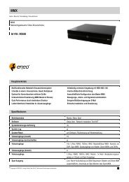
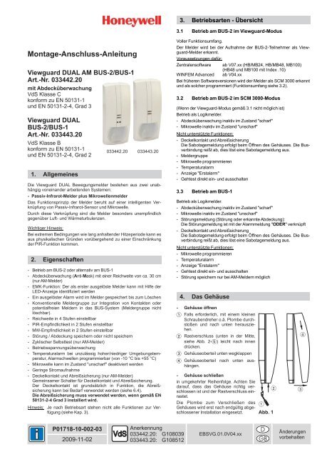
4. Das Gehäuse<br />
- Gehäuse öffnen<br />
Falls erforderlich, mit einem kleinen<br />
Schraubendreher o.ä. Plombe durchstoßen<br />
und nach unten herausziehen.<br />
Rastverschluss (unten in der Mitte,<br />
siehe Abb. 2- )<br />
leicht nach innen<br />
drücken.<br />
Gehäuseoberteil unten wegklappen<br />
Gehäuseoberteil<br />
hängen.<br />
nach unten aus-<br />
- Gehäuse schließen<br />
in umgekehrter Reihenfolge. Achten Sie<br />
darauf, dass das Gehäuse richtig verschlossen<br />
ist und der Rastverschluss einrastet.<br />
<br />
Die Plombe zum Verschließen des<br />
Gehäuses wird erst nach endgültig abge-<br />
<br />
schlossener Installation eingesetzt. Abb. 1<br />
EBSVG.01.0V04.xx<br />
D<br />
GB<br />
<br />
Änderungen<br />
vorbehalten
2 <strong>Montage</strong>-<strong>Anschluss</strong>-<strong>Anleitung</strong> Viewguard DUAL / AM BUS-2/BUS-1<br />
1 LED gelb<br />
2 LED rot<br />
3 Abdecküberwachung<br />
(nur AM-Melder)<br />
4<br />
5<br />
6<br />
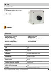
5. Aufbau des Melders<br />
Abdeckfolie für Spiegeloptik<br />
Rastverschluss<br />
Plombe<br />
Abb. 2<br />
1 Mikrowellen-Modul<br />
2 Steckkontakte für <strong>Anschluss</strong>leiste<br />
3 DIP-Schalter S1<br />
BUS-1 Programmierung<br />
(5-stellig bei AM-Melder)<br />
4 DIP-Schalter S2<br />
BUS-Adresse<br />
5 Spiegeloptik<br />
6 Schalter für Deckelkontakt<br />
und Abreißsicherung<br />
(nur AM-Melder) <br />
7 PIR-/BUS-Modul<br />
Abb. 3<br />
6. <strong>Montage</strong><br />
6.1 <strong>Montage</strong>ort<br />
<br />
Die Empfindlichkeit ist quer zu den horizontalen Erfassungszonen<br />
des PIR-Sensors am größten. Deshalb ist der <strong>Montage</strong>ort so zu wählen,<br />
dass die zu erwartende Bewegungsrichtung quer dazu verläuft<br />
( siehe Abb. 6).<br />
Mindestabstand zur Decke: 2 cm<br />
Vermeiden Sie:<br />
* <strong>Montage</strong> über Heizkörpern<br />
* <strong>Montage</strong> in der Nähe von Luftaustrittsöffnungen (z.B. Klimaanlagen)<br />
* Direkte Sonneneinstrahlung<br />
* Leuchtstofflampen in geringem Abstand<br />
* Glühlampen in geringem Abstand<br />
<br />
<br />
<br />
<br />
<br />
<br />
<br />
<br />
<br />
<br />
<br />
6.2 <strong>Montage</strong>möglichkeiten (Abb. 4 und Abb. 5)<br />
0° vertikal geneigt (Abb. 4/1)<br />
Die Befestigung erfolgt mit 2 Schrauben (Abb. 5- ).<br />
3° vertikal nach unten geneigt (Abb. 4/2)<br />
Durch diese Einstellung wird die Reichweite etwas verringert. Zu<br />
empfehlen ist dies besonders in kleinen Räumen.<br />
Befestigung mit 2 Schrauben: im unteren Bereich durch 2 Löcher<br />
auf gleicher Höhe (Abb. 5- ).<br />
45° horizontal nach links oder rechts (Abb. 4/3)<br />
Befestigung durch 2 seitliche Löcher übereinander (Abb. 5- ).<br />
Eckmontage (Abb. 4/4)<br />
Befestigung durch 2 seitliche Löcher übereinander (Abb. 5- ).<br />
Beim Festschrauben des Unterteils mit 4 Schrauben besteht die<br />
Gefahr, dass dieses sich verspannt und somit das Oberteil nicht<br />
mehr passt. Um dies zu verhindern, sollte das Unterteil nur auf einer<br />
Seite mit 2 Schrauben befestigt werden.<br />
Wenn diese Möglichkeiten nicht ausreichen, können Sie den Melder<br />
auf das Verstellgelenk (033390) oder Kugelgelenk (033588) montieren<br />
(siehe Zubehör).<br />
ACHTUNG! Melder auf Verstellgelenk gemäß VdS und EN Grad 2.<br />
Melder auf Kugelgelenk nicht gemäß VdS und EN.<br />
6.3 Kabeleinführung, Zugentlastung (siehe Abb. 5)<br />
A<br />
B C<br />
C<br />
D<br />
45°<br />
+/-0°<br />
b)<br />
45°<br />
4/1 4/2 4/3 4/4<br />
Abb. 4<br />
<br />
B<br />
C<br />
<br />
für aP Verkabelung<br />
für up Verkabelung<br />
für Verwendung mit Verstellgelenk<br />
für Zugentlastung mit Kabelbinder<br />
<br />
Abreißsicherung hier nicht möglich<br />
<br />
<br />
<br />
Abb. 5 Abb. 5a<br />
6.4 Abreißsicherung (sieheAbb. 5a)<br />
(nurAM-Melder)<br />
A<br />
B<br />
D D<br />
b<br />
a<br />
C<br />
<br />
Zwingend erforderlich bei Installation gemäß EN 50131-2-4 Grad 3<br />
Um die die Abreißsicherung zu aktivieren, entfernen Sie den Stift am<br />
Stößel a , sieheAbbildung oben.<br />
b<br />
a)<br />
c)<br />
Stößel für Abreißsicherung<br />
a<br />
mit Stift<br />
nur Deckelkontakt<br />
ohne<br />
Stift<br />
Deckelkontakt<br />
und Abreißsicherung<br />
Schutzwandung für Abreißsicherung<br />
(Rückseite)<br />
entfernen, wenn gemäß<br />
Abb. 4/3a oder 4/4 montiert<br />
wird
<strong>Montage</strong>-<strong>Anschluss</strong>-<strong>Anleitung</strong> Viewguard DUAL / AM BUS-2/BUS-1 3<br />
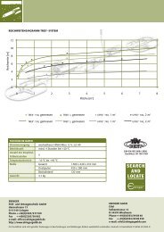
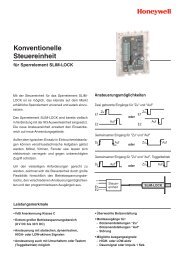
7. Strahlengang-Charakteristik<br />
Flächenoptik mit Unterkriechschutz:<br />
Optik-Aufteilung 22 Zonen auf 5 Ebenen<br />
Öffnungswinkel 80° hor., 64° vert.<br />
Reichweite PIR und MW 8 / 11 / 13 / 15 m<br />
PIR und MW arbeiten automatisch mit der gleichen Reichweite.<br />
Empfohlene <strong>Montage</strong>höhe 2,5 m für optimaleAnsprechempfindlichkeit.<br />
Soll der Melder höher als 2,5 m montiert werden, sollte er mit mindestens<br />
3° vertikal nach unten geneigt montiert werden. Eventuell ist<br />
das Verstellgelenk erforderlich.<br />
Führen Sie grundsätzlich einen Gehtest durch! (siehe 11.3)<br />
Typisches Erfassungsdiagramm bei Reichweiteneinstellung 15 m:<br />
<strong>Montage</strong> 0° Neigung<br />
2,5m<br />
9m<br />
0m<br />
9m<br />
0m<br />
MW<br />
5m 10m 15m<br />
PIR<br />
zu erwartende<br />
Bewegungsrichtung<br />
Abb. 6 0m<br />
5m 10m 15m<br />
Der Dual-Melder verfügt durch die zusätzliche Mikrowelle auch bei<br />
Diagonalbewegungen über eine hohe Detektionsfähigkeit.<br />
8. Überwachungsfunktionen<br />
8.1 Abdecküberwachung (nur AM-Melder)<br />
Der Melder erkennt ein Abdecken des Sichtfensters im Nahbereich bis<br />
ca. 30 cm. Ein Abkleben oder Besprühen der IR-Folie des Melders wird<br />
ebenfalls erkannt.<br />
Am BUS-1 und am BUS-2/SCM 3000-Modus ist die Abdecküberwachung<br />
automatisch aktiv nur im Zustand " unscharf"<br />
(Tagbetrieb und<br />
Gehtest).<br />
Am BUS-2 im Viewguard-Modus ist die Abdecküberwachung programmierbar:<br />
aktiv nur im Zustand "unscharf" / immer aktiv / immer inaktiv.<br />
Ansprechzeit: ca. 20 Sek., ca. 5 Sek. im Gehtestbetrieb.<br />
Der Referenzwert wird intern nachgeführt, so dass Änderungen durch<br />
Verschmutzung o.ä. ausgeglichen werden können und die optimale<br />
Ansprechschwelle erhalten bleibt.<br />
8.2 Selbsttest (nurAM-Melder)<br />
Im Zustand "unscharf" wird zyklisch die korrekte PIR-Funktion des<br />
Melders überwacht.<br />
Wird dabei eine Fehlfunktion festgestellt, erfolgt eine entsprechende<br />
Meldung an die Zentrale.<br />
8.3 Betriebsspannungsüberwachung<br />
Die Betriebsspannung des Melders wird auf Einhaltung des spezifizierten<br />
Minimalwertes überwacht.<br />
Wird der Minimalwert unterschritten, erfolgt eine entsprechende<br />
Meldung an die Zentrale.<br />
40°<br />
40°<br />
30°<br />
30°<br />
20°<br />
20°<br />
10°<br />
0°<br />
10°<br />
9. Programmierung<br />
9.1 VdS Hinweise<br />
Bei VdS gemäßer Installation sind folgende Punkte zu beachten:<br />
Reichweite/Empfindlichkeit:<br />
Bei einer Reichweite von 15 m ist die Empfindlichkeit "hoch"<br />
nicht zulässig.<br />
Abdecküberwachung:<br />
Die Abdecküberwachung bei AM-Meldern muss auf<br />
speichern programmiert sein.<br />
Eine gespeicherte Abdeckung verhindert das Scharfschalten.<br />
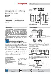
9.2 DIP-Schalter Funktion<br />
Abb. 7<br />
9.3 BUS-Teilnehmeradresse<br />
Der DIP-Schalter S2 (siehe Abb. 7) dient der Codierung der BUS-Teilnehmeradresse.<br />
Die Einstellung der Adresse ist unabhängig davon, ob der Melder am<br />
BUS-2 oder BUS-1 betrieben wird.<br />
9.4 Betrieb am BUS-2<br />
- DIP-Schalter S1/1 in Stellung "ON" stellen.<br />
(Sonst sind keine weiteren DIP-Schalter Einstellungen erforderlich.)<br />
Von der Zentrale aus lassen sich über das BUS-2-System folgende<br />
Parameter programmieren:<br />
- Reichweite 8 / 11 / 13 / 15 m (PIR und MW gemeinsam)<br />
- Empfindlichkeit PIR normal / hoch<br />
- Störung/Abdeckung - Nicht speichern:<br />
Störungsmeldung wird nach Beseitigung der<br />
Störung/Abdeckung automatisch gelöscht.<br />
- Speichern:<br />
Störungsmeldung bleibt auch nach Beseitigung<br />
der Störung/Abdeckung im Melder gespeichert<br />
bis zum Löschen (siehe 12.2).<br />
Folgende Funktionen werden nur im Viewguard-Modus unterstützt:<br />
- Abdecküberwachung aktiv nur im Zustand "unscharf" / immer aktiv /<br />
immer inaktiv<br />
- Mikrowelle - aktiv nur im Zustand "scharf" / immer aktiv /<br />
immer inaktiv<br />
- Empfindlichkeit normal / hoch<br />
- DK/Abreißsicherung aktiv oder inaktiv<br />
- Temperaturalarm Temperaturschwelle, Toleranz ±2 °C<br />
zulässiger Bereich: -10 °C bis +55 °C<br />
9.5 Betrieb am BUS-1<br />
- DIP-Schalter S1/1 in Stellung "OFF" stellen.<br />
- Parameter einstellen:<br />
S1/2 S1/3 Reichweite<br />
OFF OFF 8 m<br />
ON OFF 11 m<br />
OFF ON 13 m<br />
ON ON 15 m<br />
S1/4 Empfindlichkeit<br />
ON Normal<br />
OFF Hoch<br />
S1<br />
BUS-1/BUS-2<br />
Reichweite<br />
Empfindlichkeit<br />
ON<br />
Störung/AM nicht speichern<br />
S2<br />
1<br />
2<br />
Wertigkeit<br />
4<br />
8<br />
16<br />
32<br />
ON<br />
Beispiel: Adresse 5<br />
S1/5 nur bei AM-Meldern<br />
S1/5 Störung/Abdeck.<br />
(nur-AM Melder)<br />
ON nicht speichern<br />
OFF speichern<br />
Nicht speichern:<br />
Störungsmeldung wird nach Beseitigung<br />
der Störung/Abdeckung automatisch<br />
gelöscht.<br />
Speichern:<br />
Störungsmeldung bleibt auch nach<br />
Beseitigung der Störung/Abdeckung<br />
im Melder gespeichert bis zum<br />
Löschen (siehe 12.2).<br />
1<br />
2 3 4 5<br />
1<br />
2 3 4 5 6<br />
ON<br />
ON
4<br />
10. Installation<br />
Die Zuleitung ist als abgeschirmte, paarweise verseilte Leitung<br />
auszuführen. Die erforderlichen Querschnitte entnehmen Sie bitte der<br />
Installationsanleitung (Kapitel "Leitungen") der betreffenden Zentrale.<br />
Die <strong>Anschluss</strong>klemme arbeitet nach dem Lift-Prinzip und hat einen<br />
Untersteckschutz für die <strong>Anschluss</strong>drähte. Es kann ein Querschnitt bis<br />
2,5 mm² geklemmt werden.<br />
Die <strong>Anschluss</strong>drähte sind auf eine Länge von 7 mm ±1 mm abzuisolieren.<br />
Sind mehrere Adern pro Klemme erforderlich, ist darauf zu achten,<br />
dass deren Durchmesser gleich groß sind, um eine sichere Klemmung<br />
zu gewährleisten (evt. verdrillen).<br />
Die Schirmanschlüsse müssen so kurz wie möglich ausgeführt werden,<br />
um die Gefahr von unbeabsichtigten Kurzschlüssen zu vermeiden.<br />
Prinzip der BUS-Verdrahtung:<br />
0 V<br />
Daten<br />
+U_b<br />
Abb. 8<br />
Zentrale BUS-2/BUS-1<br />
Melder<br />
Hinweis:Am BUS darf keinAbschlusswiderstand angebracht werden.<br />
11. Inbetriebnahme<br />
11.1 Überprüfen der Installation<br />
Voraussetzung für eine sichere Funktion ist die einwandfreie Installation<br />
aller Anlagenteile. Messen Sie alle Leitungen durch, um eventuelle<br />
Leitungsunterbrechungen oder Kurzschlüsse zu erkennen.<br />
Achten Sie darauf, dass kein Erdschluss besteht.<br />
11.2 Betriebsspannung anlegen<br />
Nach dem Anlegen der Betriebsspannung führt der Melder eine<br />
Initialisierung durch. Die beiden LEDs blinken (siehe 12.1.4).<br />
Während der Initialisierung darf sich niemand im Erfassungsbereich der<br />
Abdecküberwachung des Melders aufhalten.<br />
Nach spätestens 60 Sekunden ist der Melder betriebsbereit.<br />
Danach darf in der unmittelbaren Umgebung (bis 50 cm) nichts mehr<br />
verändert werden, was die reflektierte Lichtmenge beeinflussen könnte.<br />
11.3 Gehtest<br />
Führen Sie grundsätzlich bei jedem Melder einen Gehtest durch.<br />
Hinweis: Im Viewguard-Modus lässt sich der Gehtest über die Zentrale<br />
direkt ein- und ausschalten. ("Meldergruppe löschen" und "scharfschalten"<br />
nur im SCM 3000-Modus und am BUS-1 erforderlich.)<br />
Überprüfen Sie den Überwachungsbereich des Melders.<br />
Speziell bei einer <strong>Montage</strong>höhe über 2,5 m kann es erforderlich sein,<br />
die Reichweite und die Empfindlichkeit des Melders zu erhöhen oder<br />
den <strong>Montage</strong>winkel zu verändern.<br />
Wichtig: Die Falschalarmsicherheit wird dadurch nur unwesentlich<br />
beeinträchtigt.<br />
11.4 Plombe einsetzen (sieheAbb. 2- ).<br />
Stellen Sie sicher, dass das Gehäuse richtig verschlossen ist.<br />
Setzen Sie nun die Plombe ein. Das Gehäuse ist jetzt verriegelt und<br />
lässt sich nur durch Entfernen der Plombe wieder öffnen.<br />
0 V<br />
Daten<br />
+U_b<br />
<strong>Montage</strong>-<strong>Anschluss</strong>-<strong>Anleitung</strong> Viewguard DUAL / AM BUS-2/BUS-1<br />
12. Betrieb<br />
12.1 LED-Anzeige<br />
12.1.1 Nach dem Unscharfschalten<br />
Hinweis: Ein ausgelöster Alarm bleibt im Melder gespeichert<br />
bis zum Löschen.<br />
Betrieb am BUS-2 im Viewguard Modus:<br />
(Zentralensoftware ab V07.05)<br />
Die rote LED blinkt:<br />
Es steht ein Erstalarm an.<br />
Dieser Melder hat als erster ausgelöst<br />
Die rote LED leuchtet:<br />
Es steht ein Folgealarm an.<br />
Alle nachfolgend ausgelösten Melder<br />
Betrieb am BUS-2 im SCM 3000-Modus oder am BUS-1:<br />
Die rote LED leuchtet:<br />
Es steht ein Alarm an.<br />
12.1.2 Betriebszustand "Gehtest"<br />
Die rote LED leuchtet:<br />
Bewegung erkannt<br />
Die gelbe LED blinkt:<br />
Es liegt eine Störung vor. Eine Störung wird durch eine der<br />
Überwachungsfunktionen ausgelöst (siehe Kap. 8).<br />
Die gelbe LED leuchtet:<br />
Abdeckung erkannt (nur AM-Melder)<br />
12.1.3 Betriebszustand "scharf" und "unscharf"<br />
Die LED-Anzeige ist dunkelgesteuert<br />
12.1.4 Sonderfall bei Inbetriebnahme<br />
Die gelbe und rote LEDs blinken:<br />
- Nach dem Anlegen der Betriebsspannung.<br />
- Die rote LED erlischt, sobald die Buskommunikation aufgebaut<br />
ist.<br />
- Die gelbe LED erlischt, wenn die Initialisierung abgeschlossen<br />
ist (nach ca. 30 Sekunden).<br />
- Bei fehlender oder gestörter BUS-Verbindung.<br />
12.2 Gespeicherte Abdeckung<br />
Eine gespeicherte Abdeckung verhindert das Scharfschalten der Anlage.<br />
Gespeicherte Abdeckung löschen:<br />
1. Ursache entfernen<br />
2. Gehtest aktivieren<br />
3. Melder auslösen, die gespeicherte Abdeckung wird dabei<br />
gelöscht.<br />
Der Melder ist wieder betriebsbereit.
<strong>Montage</strong>-<strong>Anschluss</strong>-<strong>Anleitung</strong> Viewguard DUAL / AM BUS-2/BUS-1<br />
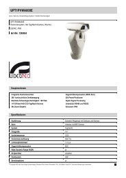
13. <strong>Anschluss</strong>plan<br />
13.1 <strong>Anschluss</strong> BUS-2 oder BUS-1<br />
Bei der Version 1 (Abb. 9) ist bei abgezogenem Melder die Spannungsversorgung und die Datenleitung für die darauf folgenden BUS-Teilnehmer<br />
unterbrochen. Falls dies nicht gewünscht wird, ist Version 2 (Abb. 10) anzuwenden.<br />
Version 1<br />
BUS-2<br />
BUS-1<br />
Abb. 9<br />
0 V<br />
Daten<br />
+12 V DC<br />
Schirm<br />
15. Zubehör<br />
ZONE<br />
0 V<br />
Daten<br />
+12 V DC<br />
Melder 1 Melder n (max. 63)<br />
033390 Verstellgelenk<br />
Schwenkbereich: Horizontal ±20°, Vertikal +4° bis -8°<br />
gemäß VdS und EN Grad 2<br />
033588 Kugelgelenk-Set für Wand- und Eckmontage<br />
Schwenkbereich: Horizontal ±45°, Vertikal ±20°<br />
nicht gemäß VdS und EN<br />
033391 Plombe (VPE = 20 Stück)<br />
0 V<br />
Daten<br />
13.2 <strong>Anschluss</strong> Meldergruppe (ZONE)<br />
+12 V DC<br />
Schirm<br />
ZONE<br />
0 V<br />
Daten<br />
+12 V DC<br />
Dieser <strong>Anschluss</strong> bietet die Möglichkeit, Kontakte in das BUS-System<br />
zu integrieren. (Nicht möglich im SCM 3000-Modus, siehe 3.2)<br />
Betrieb am BUS-2:<br />
Wird die Meldergruppe nicht verwendet, ist sie auf Meldergruppe<br />
"Null" zu programmieren!<br />
Betrieb am BUS-1:<br />
Die Meldergruppe ist mit dem Melder-Alarm ODER verknüpft. Wird<br />
die Meldergruppe nicht verwendet,<br />
ist sie mit 12k1 abzuschließen.<br />
Abb. 11<br />
0 V<br />
Daten<br />
+12 V DC<br />
Schirm<br />
BUS-2<br />
BUS-1<br />
ZONE<br />
Melder<br />
0 V<br />
Daten<br />
+12 V DC<br />
BUS-2<br />
BUS-1<br />
Kontakt(e)<br />
potentialfreie Melder<br />
ohne Speicherfunktion<br />
12k1<br />
Version 2<br />
BUS-2<br />
BUS-1<br />
Abb. 10<br />
0 V<br />
Daten<br />
+12 V DC<br />
Schirm<br />
ZONE<br />
0 V<br />
Daten<br />
+12 V DC<br />
0 V<br />
Daten<br />
+12 V DC<br />
Schirm<br />
ZONE<br />
0 V<br />
Daten<br />
+12 V DC<br />
Melder 1 Melder n (max. 63)<br />
14. Technische Daten<br />
Betriebsnennspannung U_b 12 V DC<br />
Betriebsspannungsbereich<br />
Stromaufnahme bei U_b=12 V DC:<br />
8,0 V bis 15 V DC<br />
- PIR 0,6 mA (BUS-2)<br />
3,0 mA (BUS-1)<br />
- Mikrowelle 6 mA<br />
- LED 4 mA<br />
Reichweite (programmierbar) 8 / 11 / 13 / 15 m<br />
PIR und MW gemeinsam<br />
PIR-Sensorik temperaturkompensiert<br />
PIR-Empfindlichkeit (programmierbar) normal / hoch<br />
MW-Empfindlichkeit (programmierbar) normal / hoch<br />
Abdecküberwachung (nur AM-Melder) bis 30 cm<br />
Frequenz Mikrowelle 9,35 GHz (X-Band)<br />
Einbaulage senkrecht, Optik unten<br />
Schutzart nach DIN 40 050 IP 30<br />
Umweltklasse gemäß VdS II<br />
Betriebstemperaturbereich -10 °C bis +55 °C<br />
Lagerungstemperaturbereich -25 °C bis +70 °C<br />
Abmessungen B x H x T 64 x 158 x 48 mm<br />
Farbe weiß (ähnlich RAL 9010)<br />
VSÖ-Zulassung 033442.20 VSÖ.E:W081006/28E<br />
033443.20 VSÖ.E:GS-N081006/29E<br />
Die Melder Viewguard DUAL AM BUS-2/BUS-1, Art.-Nr.<br />
033442.20 und Viewguard DUAL BUS-2/BUS-1, Art.-Nr.<br />
033443.20 entsprechen bei bestimmungsgemäßer<br />
Anwendung den grundlegenden Anforderungen gemäß<br />
Artikel 3 der R&TTE-Richtlinie 1999/5/EG.<br />
Die EU-Konformitätserklärung steht unter<br />
"www.honeywell.com/security/de"<br />
im Service-/ Downloadbereich zum Download bereit.<br />
Die Geräte dürfen nur in folgenden Ländern in den Verkehr gebracht<br />
und betrieben werden:<br />
Deutschland, Österreich, Schweiz, Liechtenstein, Polen, Slowakei,<br />
Tschechien, Luxemburg, Türkei, Griechenland, Litauen, Ungarn,<br />
Belgien, Niederlande, Bulgarien und Rumänien.<br />
5
Honeywell Security Group<br />
Novar GmbH<br />
Johannes-Mauthe-Straße 14<br />
D-72458 Albstadt<br />
www.honeywell.com/security/de<br />
P01718-10-002-03<br />
2009-11-02<br />
© 2009 Novar GmbH
Mounting and Connection Instructions<br />
Viewguard DUAL AM BUS-2/BUS-1<br />
Item no. 033442.20<br />
with Anti-Mask function<br />
VdS Class C<br />
As per EN 50131-1<br />
and EN 50131-2-4, grade 3<br />
Viewguard DUAL<br />
BUS-2/BUS-1<br />
Item no. 033443.20<br />
VdS Class B<br />
As per EN 50131-1<br />
and EN 50131-2-4, grade 2<br />
1. General<br />
The Viewguard DUAL motion detector comprises two systems that<br />
operate fully independently:<br />
- Passive infrared detector<br />
- Microwave detector<br />
The functioning principle of the detector is based on the intelligent<br />
linkage of a passive infrared sensor and microwave.<br />
This type of linking renders the detectors particularly insensitive to air<br />
and thermal turbulences.<br />
Note:<br />
Under extreme (weather) conditions, such as a long and persistent<br />
heat wave, the PIR function may be impaired for physical reasons.<br />
2. Features<br />
- Operation on BUS-2 or alternatively on BUS-1<br />
- Anti-Mask function (monitoring against covering) with a range of<br />
approx. 30 cm (only AM detector)<br />
- FAI function: The detector that is triggered first, can be identified<br />
with the aid of the LED indication.<br />
- A detected alarm remains stored in the detector until it is cleared<br />
- Detector zone for the integration of contacts or potential-free detectors<br />
in the BUS system (zone not erasable).<br />
- Range settable in 4 stages<br />
- PIR sensitivity programmable in 2 stages<br />
- MW sensitivity programmable in 2 stages<br />
- Fault/cover save or do not save<br />
- Cyclical self-test (only AM detector)<br />
- Monitoring of operating voltage<br />
- Temperature alarm for abnormally high/low ambient temperature,<br />
alarm thresholds can be programmed (from -10 ºC to +55 ºC)<br />
- Low current consumption<br />
- Microwave can be deactivated in the "disarmed" state<br />
- Tamper and backtamper (only AM detector)<br />
Common switch for tamper and backtamper.<br />
The tamper is always active, the backtamper can be used when<br />
necessary (see 6.4).<br />
The backtamper is required, if installed in compliance with EN<br />
50131-2-4, grade 3.<br />
Note:<br />
The functions that are available depend on the operating<br />
mode (see Chapter 3).<br />
P01718-10-002-03<br />
2009-11-02<br />
033442.20 033443.20<br />
approval<br />
033442.20: G108039<br />
033443.20: G108512<br />
3. Operating modes - overview<br />
3.1 Operation on BUS-2 in Viewguard mode<br />
Full range of functions.<br />
When establishing the connected BUS-2 user, a Viewguard detector is<br />
identified.<br />
Required software:<br />
Control panel from V07.xx (HB/MB24, HB/MB48, MB100)<br />
(HB48 and MB100 with index .10)<br />
WINFEM Advanced from V04.xx upward<br />
With earlier software versions, the detector is identified as an SCM<br />
3000 and should be programmed accordingly (functions see 3.2).<br />
3.2 Operation on BUS-2 in SCM 3000 mode<br />
(If Viewguard mode in accordance with 3.1 is not possible)<br />
Operation as a logic detector.<br />
- Anti-mask function inactive when “armed”<br />
- Microwave inactive when “disarmed”<br />
Functions that are not supported:<br />
- Cover contact and backtamper<br />
The tamper message is transmitted when the housing is opened.<br />
The bus connection breaks, which triggers a tamper alarm.<br />
- Detector zone<br />
- Programming microwave<br />
- Temperature alarm<br />
- “First alarm” indication<br />
- Switch “walk test” on and off directly<br />
3.3 Operation on BUS-1<br />
Operation as a logic detector.<br />
- Anti-mask function inactive when “armed”<br />
- Microwave inactive when “disarmed”<br />
- Fault message (fault or detected covering):<br />
The fault message is connected in an “OR” function with the alarm<br />
message<br />
- Cover contact and backtamper<br />
The tamper message is transmitted when the housing is opened.<br />
The bus connection breaks, which triggers a tamper alarm.<br />
Functions that are not supported:<br />
- Programming microwave<br />
- Temperature alarm<br />
- “First alarm” indication<br />
- Switch “walk test” on and off directly<br />
- It is only possible to save the fault with AM detectors<br />
4. Housing<br />
- Open housing<br />
If necessary, break the seal with a<br />
small screwdriver or similar object<br />
and pull downward.<br />
Press the notch (at the bottom in the<br />
middle, see Fig. 2- )<br />
slightly inward.<br />
Press off the front of the housing.<br />
Lift off the housing front.<br />
- Close housing<br />
in reverse order. Ensure that the<br />
housing is closed correctly and locked<br />
into position.<br />
Do not insert the seal to lock the<br />
housing until installation is completed.<br />
EBSVG.01.0V04.xx<br />
<br />
Fig. 1<br />
D<br />
GB<br />
<br />
<br />
Subject to change<br />
without notice
8 Mounting and Connection Instructions Viewguard DUAL / AM BUS-2/BUS-1<br />
5. Detector setup<br />
1 LED yellow<br />
2 LED red<br />
3 Anti-Mask sensor<br />
(only AM detector)<br />
4 Foil for mirror optics<br />
5 Notch<br />
6 Seal<br />
Fig. 2<br />
1 Microwave module<br />
2 Plug connectors for terminal<br />
strip<br />
3 DIP switch S1<br />
for BUS-1 programming<br />
( DIP 5-digit switch with AM<br />
detector)<br />
4 DIP switch S2<br />
for BUS address<br />
5 Mirror optics<br />
6 Tamper / backtamper<br />
(only AM detector)<br />
7 PIR-/BUS module<br />
Fig. 3<br />
6. Mounting<br />
6.1 Mounting site<br />
<br />
<br />
Maximum sensitivity is achieved when mounted crosswise to the horizontal<br />
detection zones of the PIR sensors. Therefore, select a mounting<br />
site that runs crosswise to the expected direction of motion. (See<br />
Fig. 6).<br />
Minimum distance to ceiling: 2 cm<br />
Avoid:<br />
* Mounting above radiators<br />
* Mounting near air discharge openings (e.g. air conditioning<br />
systems)<br />
* Direct sunlight<br />
* Mounting near to fluorescent lamps<br />
* Mounting near to light bulbs<br />
<br />
<br />
<br />
<br />
<br />
<br />
<br />
<br />
<br />
<br />
<br />
6.2 Mounting options (Fig. 4 and Fig. 5)<br />
0° Vertical (Fig. 4/1)<br />
Fix with 2 screws (Fig. 5- ).<br />
Vertical at a 3° downward angle (Fig. 4/2)<br />
This position slightly reduces the range. We recommend this<br />
position for small rooms.<br />
Fix with 2 screws: At the bottom by 2 holes at the same height<br />
(Fig.5- ).<br />
Horizontal at a 45° angle to the left or right (Fig. 4/3)<br />
Fix through 2 holes above one another at the side (Fig. 5- ).<br />
Corner mounting (Fig. 4/4)<br />
Fix through 2 holes above one another at the side (Fig. 5- ).<br />
When screwing down the back with 4 screws, it may become<br />
taught and the front of the housing may no longer fit. To avoid this,<br />
only fix the back on one side with 2 screws.<br />
Should these mounting possibilities not suffice, the detector can be<br />
mounted on the "Adjustable joint" (033390) or "Ball-and-socket set"<br />
(033588), see "Accessories.<br />
Attention! Detector on Adjustable joint as per VdS and EN grade 2.<br />
Detector on Ball-and-socket set not as per VdS und EN.<br />
6.3 Cable entry, strain relief (see Fig. 5)<br />
A<br />
B C<br />
C<br />
D<br />
Fig. 4<br />
45°<br />
+/-0°<br />
b)<br />
45°<br />
4/1 4/2 4/3 4/4<br />
<br />
B<br />
C<br />
<br />
Fig. 5<br />
For s.m. wiring<br />
For f.m. wiring<br />
For use with Adjustable joint<br />
For strain relief with cable strap<br />
<br />
6.4 Backtamper (see Fig. 5a)<br />
(only AM detector)<br />
a)<br />
c)<br />
Backtamper is not possible<br />
Tappet for backtamper<br />
a<br />
with pin<br />
Only tamper<br />
b Protective cover for backtamper<br />
(on<br />
the rear)<br />
Remove, when mounting as<br />
per Fig. 4/3a) or 4/4<br />
Required for installation according to EN 50131-2-4, grade 3.<br />
A<br />
<br />
B<br />
D D<br />
b<br />
a<br />
<br />
C<br />
<br />
<br />
Fig. 5a<br />
without<br />
pin<br />
Tamper and<br />
backtamper<br />
Remove the pin at the tappet a , if the backtamper is being used (see<br />
illustration).
Mounting and Connection Instructions Viewguard DUAL / AM BUS-2/BUS-1<br />
7. Detection coverage<br />
Area optics with sneak-by guard:<br />
Lens splitting 22 zones at 5 levels<br />
Opening angle 80° hor., 64° vert.<br />
PIR and MW range 8 / 11 / 13 / 15 m<br />
(PIR and MW operate automatically with the same range.)<br />
Recommended mounting height 2.5 m for optimal operating sensitivity.<br />
If the detector is to be mounted higher than 2.5 m, then it should be<br />
mounted with at least 3° vertical tilt down. The adjustable joint may be<br />
necessary.<br />
Carry out a walk test for each detector in all cases. (see 11.3)<br />
Typical detection coverage with range setting 15 m:<br />
Mounting 0 inclination<br />
2,5m<br />
9m<br />
0m<br />
9m<br />
0m<br />
MW<br />
8. Monitoring functions<br />
5m 10m 15m<br />
Expected<br />
direction<br />
of motion<br />
PIR<br />
Fig. 6 0m<br />
5m 10m 15m<br />
Due to the additional microwave, the dual detector has a very high<br />
detection capacity even with diagonal movement.<br />
8.1 Anti-Mask function (only AM detector)<br />
The detector identifies when the foil is covered at a distance of up to<br />
approx. 30 cm. It also identifies if the IR foil of the detector has been<br />
taped or sprayed.<br />
Operating with BUS-1 and BUS-2/SCM 3000 mode the Anti-Mask<br />
function is active only in the "disarmed" state.<br />
Operating with BUS-2/Viewguard mode the Anti-Mask function is<br />
programmable: Active only in the “disarmed” state / always active /<br />
always inactive.<br />
Reaction time: approx. 20 sec., approx. 5 sec. in walk test mode.<br />
The reference value is updated internally so that changes due to<br />
contamination, etc. can be compensated for and the optimum response<br />
threshold is maintained.<br />
8.2 Self test (onlyAM detector)<br />
In a "disarmed” state, the correct PIR-functioning of the detector is<br />
monitored in cycles.<br />
If a malfunction is detected, a corresponding message is transmitted to<br />
the control panel.<br />
8.3 Monitoring of operating voltage<br />
The detector is monitored to ensure that the specified minimum value is<br />
observed.<br />
If the minimum value is not reached, a corresponding message is<br />
transmitted to the control panel.<br />
40°<br />
40°<br />
30°<br />
30°<br />
20°<br />
20°<br />
10°<br />
0°<br />
10°<br />
9. Programming<br />
9.1 VdS notes<br />
For installation in accordance with VdS standards, the following<br />
points must be observed:<br />
Sensitiviy/range:<br />
"High" at 15 m not as per VdS<br />
Anit-Mask:<br />
The Anti-Mask function must be programmed at save.<br />
If the covered state is saved, this prevents arming.<br />
1<br />
9.2 DIP switch function<br />
S1<br />
BUS-1/BUS-2<br />
Range<br />
Sensitivity<br />
Fault/AM do not save<br />
ON<br />
S2<br />
1<br />
2<br />
Valence<br />
4<br />
8<br />
16<br />
32<br />
Fig. 7<br />
ON<br />
Example: Address 5<br />
S1/5 only AM detectors<br />
9.3 BUS user address (Fig. 7)<br />
The DIP switch S2 (see Fig. 7) is for setting the BUS user address.<br />
The address setting depends whether the detector is operated on BUS-2<br />
or BUS-1.<br />
9.4 Operation on BUS-2<br />
- Set DIP switch S1/1 in "ON" position.<br />
(No more DIP switch settings are required)<br />
The following parameters can be programmed from the control panel<br />
via the BUS-2 system:<br />
- Range 8 / 11 / 13 / 15 m<br />
- Sensitivity normal / high<br />
- Fault/AM Do not save:<br />
- Fault/cover signal is automatically cleared after<br />
elimination of the fault/cover.<br />
Save:<br />
- Fault/cover signal remains saved in the<br />
detector until it is cleared (see 12.2).<br />
The following functions are supported only in the Viewguard mode:<br />
- Anti-Mask active only in the "disarmed" state / always active /<br />
always inactive.<br />
- Microwave - active only in the "armed" state / always active /<br />
always inactive.<br />
- sensitivity normal / high<br />
- Tamper/backtamper aktive or inaktive<br />
- Temp. alarm threshold, tolerance +/-2 °C<br />
permissible range: -10 °C to +55 °C<br />
9.5 Operation on BUS-1<br />
- Set DIP switch S1/1 in "OFF" position.<br />
- Set parameters:<br />
S1/2 S1/3 Range<br />
OFF OFF 8 m<br />
ON OFF 11 m<br />
OFF ON 13 m<br />
ON ON 15 m<br />
S1/4 Sensitivity<br />
ON Normal<br />
OFF High<br />
S1/5 Fault/AM<br />
(only AM detectors)<br />
ON do not save<br />
OFF save<br />
Do not save:<br />
Fault/cover signal is automatically<br />
cleared after elimination of the fault/<br />
cover.<br />
Save:<br />
Fault/cover signal remains saved in<br />
the detector until it is cleared (see<br />
12.2).<br />
2 3 4 5<br />
1<br />
2 3 4 5 6<br />
ON<br />
ON<br />
9
10 Mounting and Connection Instructions Viewguard DUAL / AM BUS-2/BUS-1<br />
10. Installation<br />
The feed line is a shielded cable twisted in pairs. Refer to the installation<br />
instructions (Chapter “Lines”) for the required cross sections of the<br />
corresponding control panel.<br />
The connection terminal operates according to the lift principle and has<br />
protection against misplacing for the connecting wires. A cross section<br />
of up to 2.5 mm² can be fixed.<br />
The leads must be stripped to a length of 7 mm ±1 mm. If several cores<br />
are required per terminal, ensure that their diameter is of the same size<br />
to ensure secure clamping (if necessary, twisted).<br />
The shield connections must be as short as possible to avoid the risk of<br />
an unintentional short circuit.<br />
Principle of the BUS wiring:<br />
0 V<br />
Data<br />
+U_b<br />
Fig. 8<br />
Control panel BUS-2/BUS-1<br />
Detector<br />
Note: BUS terminal technology requires no end of line resistor.<br />
11. Start-up<br />
11.1 Check installation<br />
To ensure reliable functioning, all system parts must be installed<br />
correctly. Measure all the lines to detect possible interruptions or short<br />
circuits.<br />
Ensure that there is no ground fault.<br />
11.2 Apply operating voltage<br />
After applying the operating voltage, the detector automatically<br />
performs an initialisation. Both LEDs flash (see 12.1.4). Do not enter the<br />
Anti-Mask range during initialisation.<br />
After max. 60 seconds the detector is ready for operation.<br />
After this period, do not change anything in the close vicinity (up to 50<br />
cm) that may influence the reflected light.<br />
11.3 Walk test<br />
Perform a walk test for every detector (see installation instructions of<br />
the control panel).<br />
Note: In the Viewguard mode the walk test can be switched on and off<br />
directly via the contol panel. ("Clear detector group" and "arming" only<br />
required in SCM 3000 mode and BUS-1).<br />
Check the surveillance area of the detector.<br />
Especially when mounting higher than 2.5 m, it could be necessary to<br />
increase the range and the sensitivity of the detector or change the<br />
mounting angle.<br />
Important: safety from false alarms is only impaired insignificantly by<br />
this.<br />
11.4 Insert seal (see Fig. 2- ).<br />
Ensure that the housing is closed correctly.<br />
Insert the seal. The housing is now locked and can only be opened by<br />
removing the seal.<br />
0 V<br />
Data<br />
+U_b<br />
12. Operation<br />
12.1 LED indication<br />
12.1.1 After disarming<br />
Note: A detected alarm remains stored in the detector until it is<br />
cleared.<br />
BUS-2, Viewguard mode<br />
(C ontrol panel software from V07.05 upward)<br />
The red LED flashes:<br />
First alarm<br />
this detector was the first to trigger an alarm<br />
The red LED lights up:<br />
Subsequent alarm<br />
all subsequent detectors<br />
BUS-2, SCM 3000 mode or BUS-1<br />
The red LED lights up:<br />
Alarm detected.<br />
12.1.2 Operating state "Walk test"<br />
The red LED lights up:<br />
Movement detected<br />
The yellow LED flashes:<br />
This signifies that a fault has occurred. A fault is triggered by<br />
one of the monitoring functions (see Chapter 8).<br />
The yellow LED lights up:<br />
Covering detected (only AM detectors)<br />
12.1.3 Operating state "armed" and "disarmed"<br />
The LED indication is blanked<br />
12.1.4 Special case (Start-up)<br />
-<br />
-<br />
The red and yellow LEDs flash<br />
After applying the operating voltage.<br />
- As soon as the BUS communication is correct, the red<br />
LED is switched off.<br />
- As soon as the initialisation is finished, the yellow LED is<br />
switched off (after aprox. 30 sec.).<br />
If data traffic at the BUS is incorrect.<br />
12.2 Saved covered state<br />
If the covered state is saved, the system cannot be armed.<br />
Clear saved covered state:<br />
1. Remove the cause<br />
2. Activate walk test<br />
3. Trigger detector, the saved covered state is then cleared<br />
The detector is ready to operate again
Mounting and Connection Instructions Viewguard DUAL / AM BUS-2/BUS-1<br />
13. Connection diagram<br />
13.1 Connection BUS-2 or BUS-1<br />
With Version 1 (fig. 9) in the case of a removed detector the voltage supply is interrupted for the rest of the BUS users. If this is not requested then<br />
Version 2 (fig. 10) is applicable.<br />
Version 1<br />
BUS-2<br />
BUS-1<br />
Fig. 9<br />
15. Accessories<br />
033390 Adjustable joint<br />
Swivel range: Horizontal ±20°, Vertical +4° up to -8°<br />
as per VdS and EN grade 2<br />
033588<br />
0 V<br />
Data<br />
+12 V DC<br />
Shield<br />
ZONE<br />
0 V<br />
Data<br />
+12 V DC<br />
Detector 1 Detector n (max. 63)<br />
Ball-and-socket set for wall and corner mounting<br />
Swivel range: Horizontal ±45°, Vertical ±20°<br />
not as per VdS and EN<br />
033391 Seal (packaging unit = 20)<br />
0 V<br />
Data<br />
13.2 Detector group connection (ZONE)<br />
+12 V DC<br />
Shield<br />
0 V<br />
Data<br />
+12 V DC<br />
This connection enables the integration of contacts in the BUS<br />
system. (Not possible in SCM 3000 mode, see 3.2)<br />
Operation on BUS-2:<br />
If the detector zone is not used, it should be programmed to detector<br />
zone “zero”!<br />
Operation on BUS-1:<br />
The detector zone is connected in an “OR" function with the detector<br />
alarm. If the detector zone is not used, it must be terminated with<br />
12k1.<br />
Fig. 11<br />
0 V<br />
Data<br />
+12 V DC<br />
Shield<br />
BUS-2<br />
BUS-1<br />
ZONE<br />
Detector<br />
0 V<br />
Data<br />
+12 V DC<br />
BUS-2<br />
BUS-1<br />
ZONE<br />
Contact(s)<br />
potential-free detectors<br />
without memory function<br />
12k1<br />
Version 2<br />
BUS-2<br />
BUS-1<br />
Fig. 10<br />
0 V<br />
Data<br />
+12 V DC<br />
Shield<br />
ZONE<br />
0 V<br />
Data<br />
+12 V DC<br />
14. Technical data<br />
0 V<br />
Data<br />
+12 V DC<br />
Shield<br />
ZONE<br />
0 V<br />
Data<br />
+12 V DC<br />
Detector 1 Detector n (max. 63)<br />
Operating voltage U_b 12 V DC<br />
Operating voltge range 8.0 V to 15 V DC<br />
Current consumption at U_b=12 V DC:<br />
PIR 0.6 mA (BUS-2)<br />
3.0 mA (BUS-1)<br />
Microwave 6 mA<br />
LED 4 mA<br />
Range (programmable)<br />
PIR and MW together 8 / 11 / 13 / 15 m<br />
PIR sensor temperature compensated<br />
PIR sensitivity (programmable) normal / high<br />
Anti-Mask function (only AM detector) up to 30 cm<br />
Frequency microwave 9.35 GHz (X band)<br />
Installation position vertical, optics at bottom<br />
Protection class as per DIN 40 050 IP 30<br />
Environmental class as per VdS II<br />
Operating temperature range -10 °C to +55 °C<br />
Storage temperature range -25 °C to +70 °C<br />
Dimensions W x H x D 64 x 158 x 48 mm<br />
Colour White<br />
(similar to RAL 9010)<br />
VSÖ approval 033442.20 VSÖ.E:W081006/28E<br />
033443.20 VSÖ.E:GS-N081006/29E<br />
The detectors Viewguard DUAL AM BUS-2/BUS-1, Item<br />
no. 033442.20 and Viewguard DUAL BUS-2/BUS-1, Item<br />
no. 033443.20 when used as intended, comply with the<br />
basic requirements of Article 3 of the R&TTE Guideline1999/5/EU.<br />
The EU conformity declaration can be downloaded at<br />
"www.honeywell.com/security/de"<br />
under Service-/ Download<br />
The devices may only be sold and operated in the following countries:<br />
Germany, Austria, Switzerland, Liechtenstein, Poland, Slovakia, Czech<br />
Republic, Luxembourg, Turkey, Greece, Lithuania, Hungary, Belgium,<br />
Netherlands, Bulgaria and Romania.<br />
11
Honeywell Security Group<br />
Novar GmbH<br />
Johannes-Mauthe-Straße 14<br />
D-72458 Albstadt<br />
www.honeywell.com/security/de<br />
P01718-10-002-03<br />
2009-11-02<br />
© 2009 Novar GmbH