Montage-Anschluss-Anleitung
Montage-Anschluss-Anleitung
Montage-Anschluss-Anleitung

Sie wollen auch ein ePaper? Erhöhen Sie die Reichweite Ihrer Titel.
YUMPU macht aus Druck-PDFs automatisch weboptimierte ePaper, die Google liebt.
<strong>Montage</strong>-<strong>Anschluss</strong>-<strong>Anleitung</strong><br />
IDENT-KEY-Blockschloss<br />
Art.-Nr. 022220<br />
P00619-10-002-03<br />
2008-10-01<br />
Anerkennung<br />
G 196098<br />
Inhaltsverzeichnis<br />
Seite<br />
1. Sicherheitshinweise . . . . . . . . . . . . . . . . . . . . . . 2<br />
2. Allgemeines. . . . . . . . . . . . . . . . . . . . . . . . . . . . 2<br />
3. Abmessungen IDENT-KEY Blockschloss . . . . . . 3<br />
4. Blockschloss-Einbau . . . . . . . . . . . . . . . . . . . . . 4<br />
5. <strong>Anschluss</strong>hinweise. . . . . . . . . . . . . . . . . . . . . . . 9<br />
6. Technische Daten . . . . . . . . . . . . . . . . . . . . . . 10<br />
7. <strong>Anschluss</strong>plan . . . . . . . . . . . . . . . . . . . . . . . . . 10<br />
8. Das Programm . . . . . . . . . . . . . . . . . . . . . . . . 11<br />
D<br />
GB<br />
Seite 1 bis 12<br />
Page 13 to 24<br />
Änderungen<br />
vorbehalten
2<br />
1. Sicherheitshinweise<br />
Lesen Sie die <strong>Anleitung</strong> sorgfältig und vollständig durch, bevor Sie das Gerät installieren und in<br />
Betrieb nehmen.<br />
Das Gerät ist nach dem neuesten Stand der Technik gebaut.<br />
Benutzen Sie das Gerät nur:<br />
- bestimmungsgemäß und<br />
- in technisch einwandfreiem und ordnungsgemäß eingebautem Zustand<br />
- gemäß den technischen Daten.<br />
Der Hersteller haftet nicht für Schäden, die durch einen bestimmungswidrigen Gebrauch verursacht<br />
werden.<br />
Installation, Programmierung sowie Wartungs- und Reparaturarbeiten dürfen nur durch autorisiertes<br />
Fachpersonal durchgeführt werden.<br />
Löt- und <strong>Anschluss</strong>arbeiten innerhalb der gesamten Anlage sind nur im spannungslosen Zustand<br />
vorzunehmen.<br />
Lötarbeiten dürfen nur mit einem temperaturgeregeltem, vom Netz galvanisch getrennten Lötkolben<br />
vorgenommen werden.<br />
VDE-Sicherheitsvorschriften sowie die Vorschriften des örtlichen EVU sind zu beachten.<br />
Das Gerät darf nicht in explosionsgefährdeter Umgebung oder in Räumen mit<br />
metall- oder kunststoffzersetzenden Dämpfen eingesetzt werden.<br />
2. Allgemeines<br />
<strong>Montage</strong>-<strong>Anschluss</strong>-<strong>Anleitung</strong> IK2-Blockschloss<br />
Das IDENT-KEY Blockschloss dient als Schaltorgan zur Scharf-/ Unscharf-Schaltung von<br />
Einbruchmeldeanlagen in Verbindung mit den IDENT-KEY Rosetten (022167 / 022169).<br />
Der <strong>Anschluss</strong> kann an die Auswerteeinheiten 022160.10 / 022160.20 / 022164 / 022200 oder<br />
022200.10 erfolgen.<br />
Das IDENT-KEY Blockschloss empfängt über die Rosette den Code des verwendeten Schlüssels.<br />
Durch die internen Sensoren wird die Stellung des Schließbartes bzw. des Blockschlossriegels<br />
laufend überwacht.<br />
Die dabei gesammelten Informationen werden im integrierten Elektronikmodul in serielle Daten<br />
umgewandelt und an die Auswerteeinheit weitergeleitet. Ein Schließvorgang ist erst möglich, wenn<br />
ein Freigabesignal im Blockschloss vorliegt.<br />
Das Blockschloss lässt sich ohne Umbauarbeiten für DIN links- oder DIN rechts-Türen verwenden.<br />
Mit Umrüstsätzen lässt sich das Blockschloss von Dornmaß 25 mm bis auf Dornmaß 100 mm<br />
erweitern. (siehe 4.4)
<strong>Montage</strong>-<strong>Anschluss</strong>-<strong>Anleitung</strong> IK2-Blockschloss 3<br />
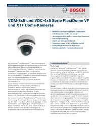
3. Abmessungen IK-Blockschloss mit Standardstulp<br />
(in mm)<br />
21<br />
241<br />
8<br />
8<br />
20<br />
3<br />
25 18<br />
40<br />
43<br />
125<br />
16<br />
151<br />
210<br />
249<br />
222,5<br />
124,2<br />
55,8<br />
28,5<br />
8<br />
10<br />
20<br />
10,5<br />
11<br />
10<br />
10,5<br />
10<br />
5,5 4,5<br />
5,5<br />
40,1<br />
10,4<br />
8,6 10,4<br />
4,5<br />
8,6<br />
5,5<br />
10,4<br />
257
4 <strong>Montage</strong>-<strong>Anschluss</strong>-<strong>Anleitung</strong> IK2-Blockschloss<br />
4. Blockschloss-Einbau<br />
4.1 Vorgehensweise<br />
1. Zylinderöffnungen im Blockschloss vor <strong>Montage</strong>beginn mit Klebeband abdecken. Dadurch wird<br />
das Eindringen von Fremdkörpern verhindert.<br />
2. Entsprechende Aussparungen für Blockschloss und Profilhalbzylinder herstellen<br />
(Bohrschablone verwenden).<br />
Dabei muss darauf geachtet werden, dass an der Unterseite der Öffnung für den<br />
Profilhalbzylinder zur Verlegung des Flachbandkabels der Rosette ausreichend Platz vorhanden<br />
ist.<br />
Ebenso dürfen die Bohrungen für die IDENT-KEY Rosette nicht vergessen werden.<br />
3. Blockschloss-<strong>Anschluss</strong>kabel im Türblatt verlegen.<br />
* Es ist zu beachten, dass sich hinter dem Blockschloss ein ausreichender<br />
Kabelvorrat der Blockschlosszuleitung befindet.<br />
Dadurch wird ermöglicht, dass bei eventuellen Störungen das Blockschloss aus<br />
der Tasche herausgenommen werden kann.<br />
* Beachten Sie beim Verlegen der Blockschlossleitung, dass im oberen Türbereich<br />
genügend Platz zum Einbau eines Reedkontaktes vorhanden ist.<br />
* Bevor das Blockschloss in die Blockschlosstasche geschoben wird, muss die<br />
Rosette am Blockschloss angeschlossen werden. Dabei muss das Flachbandkabel<br />
mit Stecker durch die Zylinderaussparung in die Blockschlosstasche<br />
und von dort nach außen geführt werden. Der Flachstecker muss dann in der an<br />
der Blockschlossrückseite vorgesehenen Buchse eingesteckt werden.<br />
Zum Höhenausgleich zwischen<br />
Rosette und Schließzylinder können<br />
ein- oder mehrere Distanzstücke<br />
(022180 / 022182) zwischen Türblatt<br />
und Rosette angebracht werden.<br />
Die Noppen am letzten Distanzstück<br />
(zur Rosette hin) müssen mit einem<br />
Messer entfernt werden.<br />
4. Blockschloss in die Blockschlosstasche einschieben und befestigen.<br />
Einsteckrichtung<br />
des Flachsteckers<br />
beachten<br />
* Beim Befestigen des Blockschlosses in der Tür ist darauf zu achten, dass die<br />
Befestigungsschrauben das <strong>Anschluss</strong>kabel nicht beschädigen.
<strong>Montage</strong>-<strong>Anschluss</strong>-<strong>Anleitung</strong> IK2-Blockschloss<br />
Bohrungen für<br />
Rosettenbestigung<br />
(Verwendung der<br />
Bohrschablone)<br />
IDENT-KEY-<br />
Rosette<br />
<strong>Anschluss</strong>kabel<br />
Achtung!<br />
An dieser Stelle<br />
ausreichend Platz<br />
für Rosetten-<br />
<strong>Anschluss</strong>kabel<br />
vorsehen!<br />
Ausschnitt<br />
Türblatt<br />
IDENT-KEY-<br />
Blockschloss<br />
5. Rosette sowie Innenschild aufsetzen und Gewindehülsen leicht anziehen.<br />
Dann wird der Zylinder durch die Rosette in die Zylinderöffnung des Blockschlosses geschoben<br />
( Schließnase in Richtung zum Stulp, 90° rechts oder links) und mit der beigefügten Schraube<br />
befestigt.<br />
Beim Einsetzen des Zylinders muss darauf geachtet werden, dass das Flachbandkabel<br />
der Rosette nicht beschädigt wird.<br />
Anschließend Gewindehülsen (Rosettenbefestigung) endgültig anziehen.<br />
6. Kabelübergang montieren.<br />
a) Darauf achten, dass die Schlauchbuchsen an den Enden des Metallschutzschlauches aufgesteckt<br />
sind. Dadurch wird eine Beschädigung des Blockschlosskabels vermieden.<br />
b) Befestigungskappen festschrauben und darauf achten, dass das Blockschlosskabel durch<br />
die Befestigungsschrauben nicht beschädigt wird.<br />
7. Schließblech anpassen und montieren.<br />
5
6 <strong>Montage</strong>-<strong>Anschluss</strong>-<strong>Anleitung</strong> IK2-Blockschloss<br />
4.2 Einbauhinweise<br />
Damit der Blockschlossriegel während der <strong>Montage</strong> ein - und ausgefahren werden kann, wird die<br />
braune Ader an +12 V und die weiße Ader an Masse angeschlossen.<br />
Die grüne und die gelbe Ader bleiben unbeschaltet. So wird das Schließen des Blockschlossriegels<br />
ohne <strong>Anschluss</strong> an die Auswerteeinheit ermöglicht. Die Anpassung des Schließbleches an den<br />
Blockschlossriegel, z. B. durch einen Schreiner oder Schlosser, ist dadurch problemlos möglich.<br />
Jetzt kann das Blockschloss über einen Profilhalbzylinder problemlos auf - und zugeschlossen<br />
werden.<br />
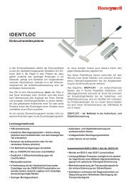
4.3 Projektierung einer Blockschlosstür<br />
Kabel vom<br />
Blockschloss<br />
zur Auswerteeinheit<br />
Riegelschaltkontakt<br />
(RSK zur Verschlussüberwachung)<br />
Türzarge<br />
Magnetkontakt<br />
Türblatt<br />
Kabelvorrat<br />
konventionelle <strong>Anschluss</strong>technik<br />
oder BUS-2 Technologie<br />
IK-Auswerteeinheit<br />
mit Summer<br />
Kabelübergang<br />
IK-Blockschloss mit<br />
Dornmaßverlängerung<br />
Schloss<br />
zur Zentrale
<strong>Montage</strong>-<strong>Anschluss</strong>-<strong>Anleitung</strong> IK2-Blockschloss<br />
4.4 Blockschlossumbau<br />
Dornmaßverlängerung<br />
Das IK-Blockschloss kann mit dem jeweiligen<br />
Umrüstsatz von Dornmaß 25 mm auf die<br />
Dornmaße 35 mm, 50 mm, 55 mm, 65 mm, 80 mm<br />
und 100 mm erweitert werden.<br />
Dornmaß 35 Art.-Nr. 022114.01<br />
Dornmaß 50 Art.-Nr. 022112<br />
Dornmaß 55 Art.-Nr. 022114.02<br />
Dornmaß 65 Art.-Nr. 022113<br />
Dornmaß 80 Art.-Nr. 022114.03<br />
Dornmaß 100 Art.-Nr. 022114.04<br />
Den werkseitig mit Standardschrauben befestigten<br />
Stulp entfernen.<br />
Umrüstsatz, bestehend aus<br />
Stulpabstandshalter,<br />
Riegelverlängerung,<br />
Riegelverschlussstopfen<br />
und Sicherungsschrauben<br />
entsprechend Zeichnung montieren.<br />
Dornmaß Schraube A Schraube B Schraube C<br />
50 M4 x 33 M4 x 30 M5 x 65<br />
65 M4 x 48 M4 x 45 M5 x 80<br />
35 M4 x 8 M4 x 14 M5 x 50<br />
55 M4 x 8 M4 x 33 M5 x 70<br />
80 M4 x 8 M4 x 48 M5 x 95<br />
100 M4 x 8 M4 x 48 M5 x 115<br />
Sonderstulp montieren<br />
Werkseitig eingesetzte Stulp- Befestigungsschrauben<br />
lösen. Stulp austauschen und mit Einweg-<br />
Sicherungsschrauben befestigen. Die Riegelabdeckplatte<br />
ebenfalls mit Einweg-Sicherungsschrauben<br />
montieren.<br />
ACHTUNG!<br />
Eine durchgeführte <strong>Montage</strong> mit den<br />
Einweg-Sicherungsschrauben lässt sich<br />
nicht mehr rückgängig machen!<br />
Stulp-<br />
Befestigungsschraube<br />
Riegelabdeckplatte<br />
Riegelverlängerung<br />
Riegelverschlussstopfen<br />
B<br />
C<br />
A<br />
Einweg-<br />
Sicherungsschrauben<br />
A<br />
7<br />
Stulpabstandshalter
8 <strong>Montage</strong>-<strong>Anschluss</strong>-<strong>Anleitung</strong> IK2-Blockschloss<br />
4.5 Blockschlossmontage hinter einer Mehrfachverriegelung<br />
(bei Holztüren)<br />
In Verbindung mit dem Sonderstulp 16 mm (Art.Nr. 022121 ) kann ein IK-Blockschloss problemlos in<br />
einer Tür mit Mehrfachverriegelung eingesetzt werden.<br />
Siehe hierzu auch Broschüre "Elektrische Installation von gefahrenmeldetechnischen Anlagen"<br />
(P03061-15-000-XX).<br />
20 mm<br />
vorhandenes<br />
Türschloss<br />
Verriegelungsgestänge<br />
geöffnet<br />
bewegliche<br />
Schubstange<br />
Blockschloss<br />
Blockierschraube<br />
Blockschloss<br />
vorhandenes<br />
Türschloss<br />
Verriegelungsgestänge<br />
geschlossen<br />
Die Blockschloss -Aussparung muss so beschaffen sein, dass bei eingesetztem<br />
Blockschloss ein Abstand von 20 mm zwischen Blockschloss-Stulp<br />
und der beweglichen Schubstange der Mehrfachverriegelung bestehen bleibt.
<strong>Montage</strong>-<strong>Anschluss</strong>-<strong>Anleitung</strong> IK2-Blockschloss<br />
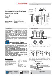
5. <strong>Anschluss</strong>hinweise / Erdung<br />
Erdung:<br />
Bitte beachten:<br />
Unter der Voraussetzung, dass der Betriebsspannungsverlust von 0,5 V DC (siehe<br />
Zeichnung) nicht überschritten wird, kann das IDENT-KEY Blockschloss bis zu 5 m von<br />
der Auswerteeinheit entfernt montiert werden.<br />
Einbruchmelderzentrale<br />
Auswerteeinheit<br />
IDENT-KEY<br />
Blockschloss<br />
+UB +UB +UB +UB<br />
0V 0V 0V 0V<br />
max. Beriebsspannungsverlust = 0,5 V<br />
max. 5 m<br />
Für die fehlerfreie Funktion einer Anlage ist die korrekte Schirmung bzw. Erdung von großer<br />
Bedeutung.<br />
Beim Einbau eines IK -Blockschlosses in eine Holztür mit Holzrahmen ist der Kabelschirm<br />
durchgehend von der Zentrale bis zum Blockschloss durchzuverbinden.<br />
Beim Einbau des Blockschlosses in eine Metalltür oder Holztür mit Metallrahmen wird der Schirm in<br />
der Auswerteeinheit unterbrochen, um eine Erdschleife zu vermeiden.<br />
Bei einer Metalltür oder Holztür mit MetaIIrahmen ist auf eine korrekte Erdung zu achten.<br />
Wenn Sie nicht sicher sind, ob der Rahmen ordnungsgemäß geerdet ist, messen Sie<br />
den Widerstand zwischen Rahmen und dem nächstgelegenen geerdeten Gegenstand<br />
(z.B. Zentralengehäuse, Heizung, Wasserleitung o.ä.).<br />
Bei richtiger Erdung messen Sie einen Widerstand
10 <strong>Montage</strong>-<strong>Anschluss</strong>-<strong>Anleitung</strong> IK2-Blockschloss<br />
6. Technische Daten<br />
Betriebsnennspannung 12 V DC<br />
Betriebsspannungsbereich 10,0 V bis 15 V DC<br />
Stromaufnahme bei Nennspannung 6 mA<br />
zusätzliche Stromaufnahme der Blockspule 120 mA<br />
Lagerungstemperaturbereich -30 °C bis +60 °C<br />
Betriebstemperaturbereich -25 °C bis +60 °C<br />
Einbaulage beliebig<br />
Schutzklasse nach DIN 40 050 IP 30<br />
Umweltklasse gemäß VdS III<br />
Abmessungen (B xH x T)<br />
Gehäusetasche 16 x 210 x 40 mm<br />
Stulp 20 x 257 x 3 mm<br />
Riegel 11 x 40 mm<br />
Riegelausschluss 15 mm<br />
Schließblech 130 x 25 x 3 mm<br />
Schließbartstellung Profilhalbzylinder<br />
(je nach Türanschlag) 90° rechts bzw. 90° links<br />
Das IK-Blockschloss 022220 entspricht bei bestimmungsgemäßer Anwendung den grundlegendenAnforderungen<br />
gemäßArtikel 3 der R&TTE-Richtlinie 1999/5/EG.<br />
Die EG-Konformitätserklärung steht auf unserer Homepage im Service/Downloadbereich<br />
zum Download bereit.<br />
7. <strong>Anschluss</strong>plan<br />
braun<br />
weiß<br />
gelb<br />
grün<br />
br<br />
ws<br />
ge<br />
gn<br />
U_b +12V DC<br />
U_b 0V<br />
Data<br />
Freigabe
<strong>Montage</strong>-<strong>Anschluss</strong>-<strong>Anleitung</strong> IK2-Blockschloss<br />
8. Das Programm<br />
Art.-Nr. 022220 IDENT-KEY-Blockschloss IK2<br />
Art.-Nr. 022167 IDENT-KEY-Rosette<br />
Farbe: schwarz<br />
Art.-Nr. 022169 IDENT-KEY-Rosette<br />
Farbe: grauweiß (ähnlich RAL 9002)<br />
Art.-Nr. 022180 Distanzstück 2,5 mm (zwischen Türblatt und Rosette)<br />
Farbe: schwarz<br />
Art.-Nr. 022182 Distanzstück 2,5 mm (zwischen Türblatt und Rosette)<br />
Farbe: grauweiß (ähnlich RAL 9002)<br />
11
Honeywell Security & Data Collection<br />
Novar GmbH<br />
Johannes-Mauthe-Straße 14<br />
P00619-10-002-03<br />
D-72458 Albstadt<br />
2008-10-01<br />
www.honeywell.com/security/de © 2008 Novar GmbH
Mounting and Connection Instructions<br />
IDENT-KEY block lock<br />
Item-No. 022220<br />
P00619-10-002-03<br />
2008-10-01<br />
Approval<br />
G 196098<br />
Contents<br />
Page<br />
1. Safety instructions .............................................14<br />
2. General information ...........................................14<br />
3. Connection diagram IDENT-KEY block lock......15<br />
4. Installation of the block lock...............................16<br />
5. Connection instructions .....................................21<br />
6. Technical data....................................................22<br />
7. Connection diagram ..........................................22<br />
8. The program ......................................................23<br />
D<br />
GB<br />
Seite 1 bis 12<br />
Page 13 to 24<br />
Subject to change<br />
without notice
14<br />
1. Safety instructions<br />
Please read these instructions carefully and completely, before installing and starting to work with<br />
this unit.<br />
The unit has been built in accordance with state-of-the-art standards.<br />
Only use the unit:<br />
- according to the designated use and<br />
- in technically perfect and correctly installed condition<br />
- according to the technical data.<br />
The manufacturer cannot be held liable for damage resulting from use contrary to the designated<br />
purpose.<br />
Installation, programming, maintenance and repair works must be carried out only by authorized<br />
trained persons.<br />
Soldering and connecting works on the entire system may only be carried out when disconnected<br />
from mains.<br />
Soldering works must only be performed with a temperature-regulated soldering iron galvanicaly<br />
separated from the mains.<br />
The safety regulations by VDE and the prescriptions of the local power utility have to be observed.<br />
The unit must no be used in explosion endangered environment or in rooms<br />
with metal- or plastic-decomposing vapours.<br />
2. General information<br />
Mounting and Connection Instructions IK2 block lock<br />
The IDENT-KEY block lock serves as switching element for arming/disarming of intrusion detection<br />
systems in combination with the IDENT-KEY rosettes (022167 / 022169). The block lock can be<br />
connected to the evaluation units 022160.10 / 022160.20 / 022164 / 022200 or 022200.10.<br />
The IDENT-KEY block lock receives the code of the corresponding key via the rosette. Internal<br />
sensors continuously monitor the position of the the block lock bar or the block lock bolt.<br />
The information collected during monitoring is converted into serial data in the integrated electronic<br />
module and transferred to the evaluation unit. The locking process is only possible when a release<br />
signal is active at the block lock.<br />
No conversion work is required when the block lock shall be used as DIN left-handed or DIN righthanded<br />
doors. The block lock can be extended from bolt length 25 mm to bolt length 100 mm with a<br />
conversion kit. (see 4.4).
Mounting and Connection Instructions IK2 block lock 15<br />
3. Dimensions IK-block lock with standard face plate<br />
(in mm)<br />
21<br />
241<br />
8<br />
8<br />
20<br />
3<br />
25 18<br />
40<br />
43<br />
125<br />
16<br />
151<br />
210<br />
249<br />
222.5<br />
124.2<br />
55.8<br />
28.5<br />
8<br />
10<br />
20<br />
10.5<br />
11<br />
10<br />
10.5<br />
10<br />
5.5 4.5<br />
5.5<br />
40.1<br />
10.4<br />
8.6 10.4<br />
4.5<br />
8.6<br />
5.5<br />
10.4<br />
257
16<br />
4. Installation of the block lock<br />
4.1 Procedure<br />
1. Cover the cylinder openings of the block lock with adhesive tape before starting the installation.<br />
This prevents the penetration of foreign objects.<br />
2. Drill corresponding recesses for block lock and profile semi-cylinder (use drilling pattern).<br />
Make sure that there is enough space at the bottom side of the opening for the profile semicylinder<br />
for laying the flat-band cable of the rosette.<br />
Do not forget to drill the holes for the IDENT-KEY rosette.<br />
3. Lay out block lock connecting cable in the door leaf.<br />
* In this case it must be observed that there is enough cable length of the block<br />
lock feed line behind the block lock.<br />
This allows to take the block lock out of the sleeve in case of a fault.<br />
* Ensure that there is enough space for the installation of a reed contact in the<br />
upper door area when laying the block lock cable.<br />
* Before the block lock is slid into the block lock sleeve the rosette has to be<br />
connected to the block lock. The flat-band cable with plug must be passed<br />
through the cylinder recess of the block lock sleeve towards the outside. Then<br />
the flat plug must be plugged into the socket provided on the rear side of the<br />
block lock.<br />
To compensate for differences in<br />
height between the rosette and the<br />
locking cylinder it is possible to<br />
mount one or several distance pieces<br />
(022180 / 022182) between door leaf<br />
and rosette.<br />
Remove the nubs of the last distance<br />
piece (towards the rosette) with a<br />
knife.<br />
4. Slide the block lock into the sleeve and fasten it.<br />
Mounting and Connection Instructions IK2 block lock<br />
Observe the plug<br />
direction of the<br />
flat plug.<br />
* When fixing the block lock in the door make sure that the fixing screws do not<br />
damage the connecting cable.
Mounting and Connection Instructions IK2 block lock 17<br />
Drill holes for<br />
rosette fixture<br />
(use the drilling pattern)<br />
IDENT-KEY<br />
rosette<br />
Connecting cable<br />
Attention!<br />
Make sure that<br />
there is sufficient<br />
space at this point<br />
for the rosette<br />
connecting cable!<br />
Door leaf<br />
section<br />
IDENT-KEY<br />
block lock<br />
5. Put on rosette and inner plate and tighten the threaded sleeves slightly.<br />
Then the cylinder is slid through the rosette into the cylinder opening of the block lock ( lock<br />
catch in direction of the face plate, 90° towards the right or the left)<br />
and then fix it with the enclosed<br />
screw.<br />
When inserting the cylinder make sure that the flat-band cable of the rosette is<br />
not damaged.<br />
Then tighten the threaded sleeves (rosette fixture) completely.<br />
6. Install the cable passage.<br />
a) Take care that the hose sockets are plugged at the ends of the protective flexible metal hose.<br />
Thus, damage of the block lock cable is avoided.<br />
b) Tighten the fixing caps and make sure that the block lock cable is not damaged by the fixing<br />
screws.<br />
7. Adjust and mount the face plate.
18<br />
4.2 Installation instructions<br />
To allow the block lock bolt to be moved in and out during the installation the brown wire has to be<br />
connected to the +12 V and the white wire to ground.<br />
The green and the yellow wire remain unconnected. Therefore, it is possible to shut the block lock<br />
bolt without connection to the evaluation unit. Thus the face plate can be adjusted easily to the block<br />
lock bolt (e.g. by a carpenter or a locksmith).<br />
Now the block lock can be locked and unlocked easily by means of the profile semi-cylinder.<br />
4.3 Project planning of a block lock door<br />
Cable from<br />
block lock to<br />
evaluation unit<br />
Bolt switching contact<br />
(BSC for lock monitoring)<br />
Door frame<br />
Magnetic contact<br />
Mounting and Connection Instructions IK2 block lock<br />
Door leaf<br />
Extra cable<br />
Conventional connecting technology<br />
or BUS-2 technology<br />
IK-evaluation unit<br />
with buzzer<br />
Door loop<br />
IK block lock with<br />
bolt extension<br />
Lock<br />
To central unit
Mounting and Connection Instructions IK2 block lock 19<br />
4.4 Conversion of the block lock<br />
Bolt length extension<br />
The IK-block lock bolt can be extended with the<br />
corresponding kit from 25 mm to bolt lengths of 35 mm,<br />
50 mm, 55 mm, 65 mm, 80 mm and 100 mm.<br />
Bolt length 35 Item-No. 022114.01<br />
Bolt length 50 Item-No. 022112<br />
Bolt length 55 Item-No. 022114.02<br />
Bolt length 65 Item-No. 022113<br />
Bolt length 80 Item-No. 022114.03<br />
Bolt length 100 Item-No. 022114.04<br />
Remove the face plate mounted at the factory with<br />
standard screws.<br />
Conversion kit, consisting of:<br />
face plate spacer,<br />
bolt extension,<br />
bolt lock plug<br />
and securing screws,<br />
mount all according to the drawing.<br />
Bolt length screw A screw B screw C<br />
50 M4 x 33 M4 x 30 M5 x 65<br />
65 M4 x 48 M4 x 45 M5 x 80<br />
35 M4 x 8 M4 x 14 M5 x 50<br />
55 M4 x 8 M4 x 33 M5 x 70<br />
80 M4 x 8 M4 x 48 M5 x 95<br />
100 M4 x 8 M4 x 48 M5 x 115<br />
Mount special face plate<br />
ATTENTION!<br />
Face plate<br />
fixing screw<br />
Bolt extension<br />
Bolt lock<br />
plug<br />
Remove the fastening screws of the face plate<br />
mounted at the factory. Replace face plate and<br />
fasten with one-way securing screws. Mount the bolt<br />
plate with one-way securing screws.<br />
The mounting with one-way securing<br />
screws cannot be undone!<br />
Bolt cover plate<br />
B<br />
C<br />
One-way<br />
securing screw<br />
A<br />
A<br />
Face plate spacer
20<br />
4.5 Block lock mounting behind a multiple locking device<br />
(wooden doors)<br />
In combination with the special face plate 16 mm (Item-No. 022121 ) an IK-block lock can be<br />
mounted easily on a door with multiple locking. Also see the folder "Electrical installation of hazard<br />
detection systems" (P03061-15-000-XX)<br />
Locking rods<br />
open<br />
20 mm<br />
Block lock<br />
Moving<br />
push rods<br />
Locking screw<br />
Existing door lock<br />
Mounting and Connection Instructions IK2 block lock<br />
Locking rods<br />
shut<br />
Block lock<br />
Existing door lock<br />
The block lock recess must be laid out so that there is a distance of 20 mm between<br />
block lock face plate and moving connecting rod of the multiple locking device when the<br />
block lock is inserted.
Mounting and Connection Instructions IK2 block lock 21<br />
5. Connection instructions / grounding<br />
Please note:<br />
Provided that the operating voltage drop does not exceed 0.5 V DC (see drawing) the<br />
IDENT-KEY block lock can be mounted at a maximum distance of 5 m to the evaluation<br />
unit.<br />
Intrusion detection<br />
control unit<br />
Evaluation unit<br />
IDENT-KEY<br />
block lock<br />
+UB +UB +UB +UB<br />
0V 0V 0V 0V<br />
Grounding:<br />
max. operating voltage drop = 0.5 V<br />
max. 5 m<br />
It is very important that the shielding, or the grounding, is realized correctly to ensure for reliable<br />
function of a system.<br />
When mounting an IK-block lock into a wooden door with wooden frame the cable shielding must<br />
lead from the central unit to the block lock without interruption.<br />
When mounting the block lock into a metal door or a wooden door with metal frame the shielding is<br />
interrupted in the evaluation unit in order to avoid grounding loop.<br />
The correct grounding has to be observed for metal doors or wooden doors with metal<br />
frame. If you are not sure whether the frame is connected to ground correctly measure the<br />
resistance between the frame and the next-possible ground-connected object (e.g.<br />
central unit housing, heating, water pipe or similar object).<br />
When the grounding is correct you can measure a resistance of
22<br />
6. Technical data<br />
Rated operating voltage 12 V DC<br />
Operating voltage range 10.0 V to 15 V DC<br />
Current consumption at rated voltage 6 mA<br />
Additional current consumption of the block coil 120 mA<br />
7. Connection diagram<br />
Mounting and Connection Instructions IK2 block lock<br />
Storage temperature range -30 °C to +60 °C<br />
Operating temperature range -25 °C to +60 °C<br />
Mounting position any<br />
International protection acc. DIN 40 050 IP 30<br />
Environmental class acc. VdS III<br />
Dimensions (W x H x D)<br />
Housing sleeve 16 x 210 x 40 mm<br />
Face plate 20 x 257 x 3 mm<br />
Bolt 11 x 40 mm<br />
Bolt throw 15 mm<br />
Face plate 130 x 25 x 3 mm<br />
Keybit position profile semi-cylinder<br />
(Depending on door stop) 90° right or 90° left<br />
The IK block lock 022220 complies with the essential requirements of the R&TTE 1999/5/EC Directive,<br />
if used for its intended use.<br />
The EC-Declaration of Conformity can be downloaded from our homepage (Service / Download).<br />
brown<br />
white<br />
yellow<br />
green<br />
brown<br />
white<br />
yellow<br />
green<br />
U_b +12V DC<br />
U_b 0V<br />
data<br />
enable
Mounting and Connection Instructions IK2 block lock 23<br />
8. The program<br />
Item-No. 022220 IDENT-KEY block lock IK2<br />
Item-No. 022167 IDENT-KEY rosette<br />
Color: black<br />
Item-No. 022169 IDENT-KEY rosette<br />
Color: greywhite (similar to RAL 9002)<br />
Item-No. 022180 Distance piece 2.5 mm (between door leaf and rosette)<br />
Color: black<br />
Item-No. 022182 Distance piece 2.5 mm (between door leaf and rosette)<br />
Color: greywhite (similar to RAL 9002)
Honeywell Security & Data Collection<br />
Novar GmbH<br />
Johannes-Mauthe-Straße 14<br />
P00619-10-002-03<br />
D-72458 Albstadt<br />
2008-10-01<br />
www.honeywell.com/security/de © 2008 Novar GmbH