Hand Surgery HBS
Hand Surgery HBS
Hand Surgery HBS

Erfolgreiche ePaper selbst erstellen
Machen Sie aus Ihren PDF Publikationen ein blätterbares Flipbook mit unserer einzigartigen Google optimierten e-Paper Software.
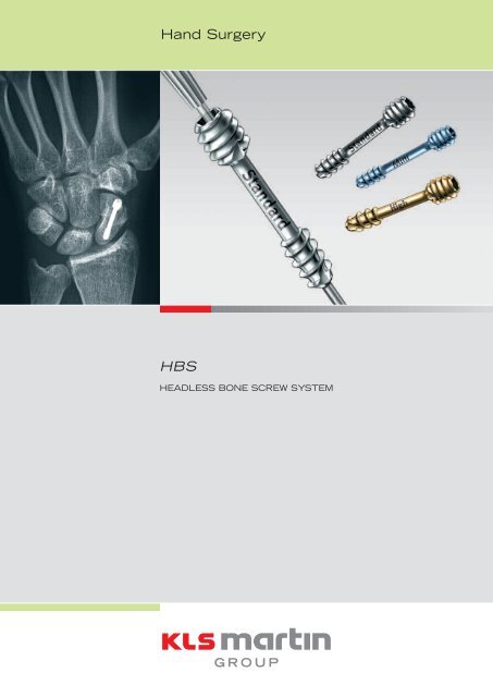
<strong>Hand</strong> <strong>Surgery</strong><br />
<strong>HBS</strong><br />
HEADLESS BONE SCREW SYSTEM
<strong>HBS</strong> – Headless Bone Screw<br />
Von allen Karpalknochen erfährt das Skaphoid, vor allem bei jungen und sportlich aktiven<br />
Menschen, die meisten Frakturen.<br />
Amongst all carpal bones the scaphoid is the most common one to sustain a fracture,<br />
especially as far as young and active people are concerned.<br />
Einleitung<br />
Die Immobilisierung durch Gipsverband über mehrere Monate<br />
blieb für die Mehrzahl der Skaphoidfrakturen lange Zeit die<br />
gängigste Behandlungsmethode, die jedoch für die überwiegend<br />
jungen und sportlich aktiven Patienten eine erhebliche Einschränkung<br />
und gleichzeitig lange Arbeitsunfähigkeit bedeutet.<br />
Die gestiegene Anspruchshaltung der betroffenen Patienten<br />
erfordert eine bessere Versorgung mit der Möglichkeit der Frühmobilisierung<br />
und des schnellen Wiedererlangens einer normalen<br />
Funktion. Das erfolgreich bewährte <strong>HBS</strong>-System von Gebrüder<br />
Martin bietet mit seiner komplett im Knochen versenkbaren<br />
kanülierten Schraube eine exzellente Primärstabilität bei Versorgung<br />
der intraartikulären oder gelenknahen Frakturen.<br />
Dem Chirurg bietet das System zwei Schraubentypen, die unterschiedliche<br />
Kompressionskräfte entwickeln (Standard- oder hohe<br />
Kompression). Die exakte Positionierung der <strong>HBS</strong>-Schraube im<br />
Knochen wird durch die Verwendung eines 1 mm starken Führungsdrahtes<br />
erleichtert, der die Verwendung eines Zielgeräts<br />
überflüssig macht. Durch die Ergänzung des Systems mit speziellem<br />
Instrumentarium für den minimal-invasiven Zugang eröffnet<br />
das <strong>HBS</strong>-System die Möglichkeit, die Vorteile der internen Fixation<br />
zu nutzen, ohne die Nachteile der großen offenen Chirurgie<br />
in Kauf nehmen zu müssen.<br />
Der T-Drive-Schraubendreher ermöglicht ein sicheres und genaues<br />
Einbringen der selbsthaltenden Schrauben. Die 1-mm-<br />
Abstufung der Implantate in den Längen von 10-30 mm bietet<br />
eine hohe Präzision bei der Osteosynthese und deckt gleichzeitig<br />
ein umfassendes Indikationsgebiet im Bereich der <strong>Hand</strong>chirurgie<br />
ab, wie die hier aufgeführten Indikationsbeispiele zeigen:<br />
Indikationen<br />
•<br />
•<br />
•<br />
•<br />
•<br />
•<br />
•<br />
•<br />
•<br />
•<br />
•<br />
•<br />
•<br />
•<br />
•<br />
•<br />
•<br />
•<br />
Kahnbeinfrakturen<br />
Karpalfrakturen und Pseudarthrosen<br />
Mittelhandfrakturen<br />
Distale Radiusfrakturen (artikuläre Fragmente)<br />
Griffelfortsatzfrakturen der Ulna<br />
Proximale Radiuskopffrakturen<br />
Kapitellumfrakturen<br />
Humeruskopffrakturen<br />
Frakturen der Cavitas glenoidalis<br />
Interkarpale Fusionen<br />
Interphalangeale Fusionen<br />
Mittelfußosteotomien<br />
Tarsalfusionen<br />
Knöchelfrakturen<br />
Patellafrakturen<br />
Osteochondrale Frakturen<br />
Densfrakturen<br />
Unterkieferfrakturen<br />
Vorteile<br />
•<br />
•<br />
•<br />
•<br />
•<br />
•<br />
•<br />
•<br />
•<br />
Kanülierte Schraube für 1-mm-Führungsdraht<br />
Schraube im Knochen versenkbar<br />
Zwei verschiedene Kompressionsstufen<br />
Selbsthaltende T-Drive-Aufnahme<br />
Beide Gewinde selbstschneidend<br />
1-mm-Abstufung der Schrauben<br />
Rotationsstabilität<br />
Optimierte Instrumente für Freihand-Technik<br />
Frühbeübbarkeit
Introduction<br />
For the majority of scaphoid fractures immobilisation in plaster<br />
has been the most common method of treatment for a long<br />
time. This approach however means a substantial restriction as<br />
well as long periods of inability to work for predominantly young<br />
and active people. Increasing expectations of the patients<br />
require better treatment that enables early mobilisation and<br />
fast regaining of normal function. With its non-protrusive<br />
canulated screw from the successfully approved <strong>HBS</strong>-system<br />
Gebrueder Martin offers excellent primary stability for the treatment<br />
of intra-articular fractures or those adjacent to a joint.<br />
The System offers the surgeon two screw types, which develop<br />
different compression forces (standard or high compression).<br />
Accurate positioning of the <strong>HBS</strong> screw is facilitated by the use<br />
of a 1 mm guide wire eliminating the need for a jig. The introduction<br />
of special supplementary instruments to our system<br />
enables osteosyntheses with minimal invasive approach.<br />
Therefore the <strong>HBS</strong>-system offers all the advantages of internal<br />
fixation whilst avoiding the disadvantages of open surgery.<br />
The T-Drive-screwdriver enables a safe and exact insertion of<br />
the self retaining screws. The implants range from 10-30 mm<br />
in 1 mm steps offering high precision of the osteosynthesis<br />
and also covering an extensive indication area within the field<br />
of hand surgery, as examples listed below demonstrate:<br />
N 200<br />
165<br />
150<br />
N<br />
100<br />
50<br />
0<br />
T<br />
Standardkompression<br />
Standard compression<br />
Schraubengewinde bündig mit Knochenoberfläche<br />
Screw thread is levelled with surface<br />
0,5 1 1,5 2 2,5 3 3,5 3,5 4 4,5 5<br />
Drehungen des Schraubendrehers<br />
Turns of the screwdriver<br />
Indications<br />
•<br />
•<br />
•<br />
•<br />
•<br />
•<br />
•<br />
•<br />
•<br />
•<br />
•<br />
•<br />
•<br />
•<br />
•<br />
•<br />
•<br />
•<br />
Scaphoid fractures<br />
Carpal fractures and nonunions<br />
Metacarpal fractures<br />
Distal radial fractures (articular fragments)<br />
Ulnar styloid fractures<br />
Radial head fractures<br />
Capitellum fractures<br />
Humeral head fractures<br />
Glenoid fractures<br />
Inter-carpal fusions<br />
Inter-phalangeal fusions<br />
Metatarsal osteotomies<br />
Tarsal fusions<br />
Malleolar fractures<br />
Patellar fractures<br />
Osteochondral fractures<br />
Odontoid fractures<br />
Mandibular fractures<br />
Advantages<br />
•<br />
•<br />
•<br />
•<br />
•<br />
•<br />
•<br />
•<br />
•<br />
1<br />
N 250<br />
223<br />
200<br />
150<br />
100<br />
50<br />
0<br />
Hohe Kompression<br />
High compression<br />
Schraubengewinde bündig mit Knochenoberfläche<br />
Screw thread is levelled with surface<br />
0,5 1 1,5 2 2,5 3 3,5 4 4,5 5<br />
Drehungen des Schraubendrehers<br />
Turns of the screwdriver<br />
Cannulated screw for 1-mm guide wire<br />
Recessed screw (flush with bone surface)<br />
Two compression stages<br />
Self-retaining T-Drive<br />
Both threads are self-tapping<br />
Screw length in 1-mm increments<br />
Rotation stability<br />
Optional instruments for the free-hand-method<br />
Early mobilisation<br />
3
Operationstechnik<br />
Surgical Technique<br />
26-350-03<br />
26-350-05<br />
26-350-01<br />
26-350-07<br />
26-350-05<br />
Abb. 1: Die Bohrhülse wird mit dem <strong>Hand</strong>griff<br />
zusammenmontiert (26-350-03 in<br />
26-350-01) und anschließend sorgsam auf<br />
dem zu fixierenden Knochen positioniert.<br />
ACHTUNG:<br />
Alles Weichgewebe, welches den Knochen<br />
bedeckt, muss sorgfältig entfernt werden,<br />
so dass die Spitzen der Bohrhülse fest im<br />
Knochen verankert werden können. Nur so<br />
lassen sich ungewollte Verschiebungen der<br />
Bohrhülse vermeiden und eine spätere<br />
exakte Längenkalibrierung sicherstellen.<br />
Es empfiehlt sich, die korrekte Position<br />
und Ausrichtung der Bohrhülse – wovon<br />
Einführpunkt und Richtung des Führungsdrahtes<br />
abhängen – mittels eines Bildwandlers<br />
zu kontrollieren.<br />
Abb. 2: Nach optimaler Positionierung<br />
der Bohrhülse wird die Reduzierhülse<br />
(26-350-05) in diese eingeführt, um<br />
den Führungsdraht (26-351-00 oder<br />
26-350-00) exakt zu platzieren. Dieser<br />
Führungsdraht wird nun unter Bildwandlerkontrolle<br />
langsam eingebracht und<br />
optimal – d. h. senkrecht zur Fraktur/<br />
Fusion und zentrisch in beiden Ebenen<br />
des Knochens – positioniert.<br />
Die Spitze des Führungsdrahts sollte in<br />
die gegenüberliegende Knochenkortikalis<br />
ein-, diese aber nicht durchdringen.<br />
Optional kann hierfür auch der Führungsdraht<br />
mit Gewindespitze (26-350-00)<br />
verwendet werden, der durch seinen größeren<br />
Halt im Knochen bei den nachfolgenden<br />
Operationsschritten nicht so schnell<br />
herausgezogen werden kann.<br />
Abb. 3: Nun wird ein 1 mm starker Fixationsdraht<br />
(26-351-00) durch eines der<br />
sechs Löcher im Haltering des <strong>Hand</strong>griffs<br />
eingeführt. Er kann unter Bildwandlerkontrolle<br />
durch den Fraktur- bzw. Fusionssitus<br />
hindurchgeführt werden, damit bei Einführung<br />
der Schraube eine gute Reduktion<br />
gegeben ist. Nachdem der Draht optimal<br />
positioniert ist, kann das überstehende<br />
Ende entweder umgebogen oder abgeschnitten<br />
werden, damit es den Zugang<br />
zur Bohrhülse nicht behindert. Nach<br />
Abschluss des Operationsverfahrens wird<br />
der Draht entweder wieder entfernt oder<br />
bündig mit der Knochenoberfläche abgeschnitten<br />
und als 2-Punkt-Fixation in<br />
Position gelassen.<br />
Abb. 4: Nach korrekter Positionierung<br />
des Fixationsdrahtes wird die Messhülse<br />
(26-350-07) über das vorstehende Ende<br />
des Führungsdrahtes geschoben, um die<br />
genaue Länge der benötigten Schraube<br />
zu ermitteln.<br />
ACHTUNG:<br />
Für eine exakte Längenmessung müssen<br />
die Spitzen der Bohrhülse fest in der<br />
Knochenoberfläche verankert sein.<br />
Außerdem muss die Messhülse beim<br />
Messvorgang auf der Reduzierhülse<br />
aufliegen.<br />
CD-ROM mit OP-Technik<br />
CD-ROM surgical technique<br />
(90-139-39-04)<br />
Fig. 1: The drill guide is assembled<br />
(26-350-03 into 26-350-01) and is<br />
then carefully positioned on the bone<br />
to be fixed.<br />
ATTENTION:<br />
It is important to carefully remove any soft<br />
tissue overlying the bone, since the points<br />
on the tip of the guide must be engaged in<br />
bone, both to prevent ‘wandering’ and to<br />
ensure accurate length calibration.<br />
The position and alignment of the guide<br />
may be checked on an image intensifier,<br />
as these will determine the insertion point<br />
and direction of the guide wire.<br />
Fig. 2: Once the drill guide is in optimum<br />
position, the reduction sleeve (26-350-05)<br />
is introduced into the drill guide in order to<br />
control accurately the position of the guide<br />
wire (26-351-00 or 26-350-00). The guide<br />
wire is advanced slowly, under x-ray control,<br />
to ensure that it is optimally positioned<br />
perpendicular to the fracture/fusion, in the<br />
mid-axis of the bone. Its tip should enter,<br />
but not penetrate the opposite cortex of the<br />
bone. The optional tip-threaded guide wire<br />
(26-350-00) may be used to reduce the risk<br />
of the wire backing out during subsequent<br />
stages of the procedure.<br />
Fig. 3: A 1 mm fixation wire (26-351-00)<br />
is now passed through one of the six peripheral<br />
holes of the collar of the guiding<br />
handle (26-350-01); this pin may be<br />
advanced accross the fracture/fusion site<br />
under x-ray control, in order to maintain a<br />
good reduction during insertion of the screw.<br />
When its position is judged satisfactory,<br />
the protruding end of the fixation wire<br />
should be bent or cut short, so that it does<br />
not obstruct access to the guide. At the end<br />
of the procedure it is either removed, or<br />
else cut flush to the bone surface and left<br />
in position to provide two-point fixation.<br />
Fig. 4: Once the fixation wire is in the<br />
correct position, the measuring sleeve<br />
(26-350-07) is passed over the protruding<br />
end of the guide wire to determine the<br />
required drilling depth.<br />
ATTENTION:<br />
To ensure accurate length measurement,<br />
the tip of the drill guide must remain firmly<br />
applied to the surface of the bone, and the<br />
measuring sleeve must be pushed over the<br />
guide wire as far as possible.<br />
Alu-Schild mit OP-Technik, sterilisierbar<br />
(90-833-01)<br />
Aluminium plate with surgical technique,<br />
sterilizable (90-833-02)
26-350-09<br />
26-350-11<br />
26-350-17<br />
3,9 mm<br />
2,0 mm<br />
3,0 mm<br />
Abb. 5: Die Reduzierhülse wird nun aus dem<br />
Einsatz herausgezogen und der kanülierte<br />
Bohrer (26-350-09) über den Führungsdraht<br />
geschoben, nachdem zuvor die mit der Messhülse<br />
ermittelte Bohrtiefe korrekt eingestellt,<br />
d. h. mit der unteren Rändelschraube fixiert<br />
wurde. Der Bohrer wird nun entlang des Führungsdrahts<br />
vorsichtig und unter Bildwandlerkontrolle<br />
so weit eingebracht, bis die Rändelschraube<br />
auf der Bohrhülse aufsetzt.<br />
HINWEIS:<br />
Es empfiehlt sich, den Bohrer während des<br />
Bohrvorgangs je nach Bedarf ein- oder mehrmals<br />
herauszuziehen und zu säubern, damit<br />
der Führungsdraht nicht durch das Bohrmehl<br />
im Bohrer verklemmt wird. Andernfalls nämlich<br />
wird der Führungsdraht beim Entnehmen<br />
des Bohrers mit herausgezogen und muss<br />
anschließend erneut korrekt platziert werden<br />
(ggf. unter Zuhilfenahme der Reduzierhülse),<br />
bevor mit Schritt 6 fortgefahren werden kann.<br />
Zur Einbringung des Führungsdrahtes und des<br />
kanülierten Bohrers verwendet man am besten<br />
eine kleine Bohrmaschine mit niedriger Drehgeschwindigkeit.<br />
Alternativ kann der kanülierte<br />
Bohrer mit Hilfe des im Set verfügbaren Bohrhandgriffs<br />
(26-350-11) natürlich auch manuell<br />
eingebracht werden.<br />
Abb. 6: Mit dem Schraubendreher<br />
(26-350-17) wird nun eine Schraube<br />
passender Länge (26-300-xx oder<br />
26-310-xx ) aus dem Rack entnommen<br />
und über den Führungsdraht implantiert,<br />
bis beim Eindringen des größeren Gewindes<br />
in den Knochen zunehmend Widerstand<br />
spürbar wird.<br />
HINWEIS:<br />
Sollte für eine optimale Fixation erhöhte<br />
Kompression erforderlich sein (z. B. im<br />
Falle einer Pseudarthrose), kann statt<br />
der Standard-Kompressionsschraube<br />
(26-300-xx) die hohe Kompressionsschraube<br />
(26-310-xx) verwendet werden.<br />
Wegen der interfragmentären Kompression<br />
empfehlen wir, eine Schraubenlänge zu<br />
wählen, die 2 mm kürzer ist als die<br />
eingestellte Bohrtiefe.<br />
Abb. 7: Der Führungsdraht sollte nun entfernt<br />
und anschließend die Schraube mit<br />
dem Schraubendreher komplett eingebracht<br />
werden. Dabei sollte darauf geachtet werden,<br />
dass, sobald der Schraubendreher an<br />
der Bohrhülse anschlägt, nicht mehr weitergedreht<br />
wird.<br />
ACHTUNG:<br />
Der Führungsdraht sollte stets entnommen<br />
werden, bevor die Schraube fest angezogen<br />
wird. Andernfalls kann es passieren, dass<br />
die Drahtspitze umgebogen wird und der<br />
Führungsdraht sich anschließend nicht<br />
mehr herausziehen lässt.<br />
Abb. 8: Der <strong>Hand</strong>griff mit Bohrhülse wird<br />
nun entfernt und die Schraube noch ein bis<br />
zwei Umdrehungen eingedreht, damit das<br />
größere Gewinde bis leicht unterhalb der<br />
Knochenoberfläche versenkt ist.<br />
Sollte es beim Neuansetzen des Schraubendrehers<br />
Probleme geben, kann der<br />
Führungsdraht noch einmal lose positioniert<br />
werden, um die Schraubendreherspitze<br />
gut in der Schraube zu zentrieren.<br />
Fig. 5: The reduction sleeve is now removed<br />
from the drill guide and the cannulated drill<br />
(26-350-09) is passed over the guide wire,<br />
the drill stop having been set at the depth<br />
indicated by the measuring sleeve.<br />
The drill is carefully advanced along the<br />
guide wire under x-ray control, until the<br />
drill stop reaches the end of the drill guide,<br />
indicating that the drill has reached its<br />
full depth.<br />
ATTENTION:<br />
It is recommended that the drill is withdrawn<br />
and cleaned one or more times during<br />
insertion, to prevent it from ‘binding’ to the<br />
guide wire; should this occur, the guide wire<br />
is likely to be withdrawn with the drill, in<br />
which case it should be repositioned (using<br />
the reduction sleeve if necessary) before<br />
moving to the next stage (Step 6).<br />
Insertion of the guide wire and of the<br />
cannulated drill is best done using a suitable,<br />
slow-speed, small power instrument.<br />
If not available, then insertion of the cannulated<br />
drill may be done by hand, using<br />
the drill handle (26-350-11) contained<br />
in the set.<br />
Fig. 6: The screwdriver (26-350-17) is used<br />
to lift a screw (26-300-xx or 26-310-xx ) of<br />
correct length from the rack in the tray.<br />
The screw is passed over the guide wire and<br />
is inserted until increased resistance is felt<br />
as the trailing thread enters the bone<br />
.<br />
ATTENTION:<br />
Should increased compression be required<br />
in order to produce optimum fixation (for<br />
example in the case of a nonunion) then<br />
the high compression screw (26-310-xx)<br />
may be selected in preference to the<br />
standard screw (26-300-xx).<br />
Due to interfragmentary compression we<br />
recommend to select a screw length which is<br />
2 mm shorter than the adjusted drill depth.<br />
Fig. 7: At this stage the guide wire should<br />
be removed, the screwdriver re-inserted and<br />
the screw advanced until the screwdriver<br />
abuts on the end of the drill guide.<br />
ATTENTION:<br />
The guide wire should always be removed<br />
before the screw is fully tightened; otherwise,<br />
its tip may become bent, making it<br />
impossible to remove.<br />
Fig. 8: The drill guide is now removed,<br />
and the screw is advanced a further one<br />
or two turns, in order to ensure that the<br />
trailing thread is well buried beneath the<br />
surface of the bone. If there is any difficulty<br />
in re-engaging the screwdriver, this may be<br />
facilitated by loosely repositioning the guide<br />
wire and using it to centre the end of the<br />
screwdriver in the socket of the screw.<br />
5
Literatur<br />
Reference List<br />
•<br />
•<br />
•<br />
•<br />
•<br />
•<br />
•<br />
•<br />
•<br />
•<br />
•<br />
•<br />
Filan S L, Herbert T J:<br />
Herbert Screw Fixation of Scaphoid Fractures,<br />
J. Bone Joint Surg., 78-B 519-529, 1996<br />
Gelbermann R H, Wollock B S, Siegel D B:<br />
Current Concepts Review: Fractures and Nonunions of the Carpal Scaphoid,<br />
J. Bone Joint Surg., 71-A, 1560-1565, 1989<br />
Herbert T J:<br />
The Fractured Scaphoid, St. Louis,<br />
Quality medical Publishing, 1990<br />
Herbert T J, Carter P:<br />
Surgical Techniques for Fixation of Scaphoid and other Small Bones,<br />
Zimmer Inc., Warsaw, Indiana, 1993<br />
Hung L-K, Pang K-W:<br />
Percutaneous Screw Fixation of Acute Scaphoid Fractures,<br />
J.<strong>Hand</strong> Surg., 19-B Supplement 1.26, 1994<br />
Inoue G, Shionoya K:<br />
Herbert Screw Fixation by Limited Access for Acute Fractures of the Scaphoid,<br />
J. Bone Joint Surg., 79-B, 418-421, 1997<br />
Kozin S H:<br />
Internal Fixation of Scaphoid Fractures,<br />
<strong>Hand</strong> Clinics 13 (4), 573-586, 1997<br />
Krimmer H, Kremling E, Schoonhoven J, Pommersberger K-J, Hahn P:<br />
Proximale Kahnbeinpseudarthrose-Rekonstruktion durch dorsale Verschraubung<br />
und Spongiosa-Transplantation,<br />
<strong>Hand</strong>chir. Mikrochir. Plast. Chir. 3, 174-177, 1999<br />
Ledoux P, Chahidi N, Moermans J P, Kinnen L:<br />
Osteosynthèse Percutanée du Scaphoide par Vis de Herbert,<br />
Acta Orthopaedica Belgica, 61-1, 43-46, 1995<br />
Pommersberger K-J, Krimmer H, Lanz U:<br />
Aktuelle Therapie der Scaphoidpseudarthrose,<br />
Akt. Traumatol. 26, 173-178, 1996<br />
Rettig A C, Kollias S C:<br />
Internal Fixation of Acute Stable Scaphoid Fractures in the Athlete,<br />
Am. J. Sports Med. 24 (2), 182-186, 1996<br />
Werber K D., Hirgstetter C:<br />
The Early Treatment of Scaphoid Fracture with a Scaphoid Screw,<br />
J. <strong>Hand</strong> Surg., 19-B Supplement 1. P26, 1994<br />
11
<strong>HBS</strong> Mini<br />
Die miniaturisierte Version der Headless Bone Screw (<strong>HBS</strong> Mini) hat einen Schaftdurchmesser von nur<br />
1,5 mm und übernimmt die Vorteile des einzigartigen Schraubendesigns mit dem doppelten Gewinde zur<br />
Fixierung von sehr kleinen Knochenfragmenten.<br />
The minituarised version of the Headless Bone Screw (<strong>HBS</strong> Mini) has a shaft diameter of only 1.5 mm,<br />
thus extending the advantages of the unique, double-threaded screw design to the fixation of extremely<br />
small bone fragments.<br />
Zu Beginn wurde die Mini <strong>HBS</strong> für die Fixierung von<br />
kleinen, proximalen Polfrakturen des Skaphoids entwickelt.<br />
Sie hat sich bereits in einer Reihe von Behandlungsmöglichkeiten<br />
bewährt, wie:<br />
•<br />
•<br />
•<br />
•<br />
•<br />
•<br />
•<br />
•<br />
•<br />
•<br />
•<br />
•<br />
Proximale Polfrakturen des Kahnbeins<br />
Distale und Frakturen in der Taille des Kahnbeins<br />
Bei kleinen Patienten<br />
Lunatumfrakturen<br />
Capitellumfrakturen<br />
Trapeziumfrakturen<br />
Mittelhand- und Mittelfuß-Frakturen<br />
Kondylenfrakturen der Finger<br />
Proximale Radiuskopffrakturen<br />
Griffelfortsatzfrakturen der Ulna<br />
Osteochondrale Frakturen<br />
Kleine Gelenksfusionen<br />
Die klinische Erfahrung hat gezeigt, dass dies das<br />
optimale Implantat für die Versorgung von proximalen<br />
Polfrakturen des Kahnbeins ist. Durch das Implantat<br />
ist das <strong>Hand</strong>gelenk ausreichend gesichert, um es aktiv<br />
zu beanspruchen. Somit werden auch die Probleme<br />
vermieden, die durch eine lange Bewegungseinschränkung<br />
eines Unterarmgipses entstehen.<br />
Die <strong>HBS</strong> Mini-Schraube nimmt 50 % weniger Platz im<br />
Knochen ein als das Standardimplantat. Dies optimiert<br />
die Bedingungen für eine Wiederherstellung der Durchblutung<br />
und einer verbesserten Heilung.<br />
Die Einbringung der <strong>HBS</strong> Mini-Schraube ist schnell<br />
und einfach. Nur ein einziges Bohrloch ist notwendig,<br />
da beide Gewinde selbstschneidend sind.<br />
Die Messskala am Bohrer erleichtert eine akkurate<br />
Längenausrichtung des Bohrers, welcher von <strong>Hand</strong><br />
oder mit einem Motor eingebracht werden kann.<br />
Die Einteilung der Messskala erfolgt in 1-mm-Schritten.<br />
Dies gewährleistet die Einbringung der korrekten<br />
Schraubenlänge.<br />
Vorteile<br />
•<br />
•<br />
•<br />
•<br />
•<br />
•<br />
Schraube im Knochen versenkbar<br />
Selbsthaltende T-Drive-Aufnahme<br />
Beide Gewinde selbstschneidend<br />
1-mm-Abstufung der Schrauben<br />
Rotationsstabilität<br />
Frühbeübbarkeit
Originally developed for the fixation of small, proximal<br />
pole fractures of the scaphoid, the Mini <strong>HBS</strong> has<br />
proved useful in a range of applications including:<br />
•<br />
•<br />
•<br />
•<br />
•<br />
•<br />
•<br />
•<br />
•<br />
•<br />
•<br />
•<br />
Scaphoid fractures – proximal pole<br />
Scaphoid fractures – waist and distal<br />
In small patients<br />
Lunate fractures<br />
Capitate fractures<br />
Trapezial fractures<br />
Metacarpal and metatarsal fractures<br />
Phalangeal fractures (condylar)<br />
Radial head fractures<br />
Ulnar styloid fractures<br />
Osteo-chondral fractures<br />
Small joint fusions<br />
Clinical experience has shown that this is the implant<br />
of choice for proximal pole fractures of the scaphoid:<br />
fixation is sufficiently secure to allow for active use of<br />
the wrist, thus avoiding the problems associated with<br />
prolonged immobilisation in plaster. Furthermore, the<br />
conditions for revascularisation and healing are optimised,<br />
due to the fact that the Mini <strong>HBS</strong> takes up 50 %<br />
less space within the bone than a standard implant.<br />
Insertion of the <strong>HBS</strong> Mini is quick and simple:<br />
only a single drill hole is required, since both<br />
threads of the screw are self-tapping. The specially<br />
designed drill-guide facilitates accurate alignment<br />
of the drill, which may be power- or hand-driven.<br />
The drill is calibrated in 1 mm increments, thus<br />
ensuring that an implant of exactly the right length<br />
is inserted.<br />
Advantages<br />
•<br />
•<br />
•<br />
•<br />
•<br />
•<br />
Standard Mini High Compression<br />
scale 1:1<br />
Recessed screw (flush with bone surface)<br />
Self-retaining T-Drive<br />
Both threads are self-tapping<br />
Screw length in 1-mm increments<br />
Rotation stability<br />
Early mobilisation<br />
13
Operationstechnik<br />
Surgical Technique<br />
26-370-03 26-350-01<br />
26-370-09<br />
Schritt 1: Bohrhülse<br />
Die Bohrhülse wird mit dem <strong>Hand</strong>griff zusammenmontiert<br />
(26-370-03 in 26-350-01)<br />
und anschließend sorgsam auf dem zu<br />
fixierenden Knochen positioniert.<br />
Die zwei Einkerbungen auf der Bohrhülse<br />
ermöglichen eine nahe oder weiter entfernte<br />
Positionierung des <strong>Hand</strong>griffs zum proximalen<br />
Fragment.<br />
Achtung:<br />
Alles Weichteilgewebe, welches den Knochen<br />
bedeckt, muss sorgfältig entfernt werden,<br />
so dass die Spitzen der Bohrhülse fest im<br />
Knochen verankert werden können. Nur so<br />
lassen sich ungewollte Verschiebungen der<br />
Bohrhülse vermeiden und eine spätere<br />
exakte Längenkalibrierung sicherstellen.<br />
Schritt 2: Vorübergehende Drahtfixierung<br />
(optional)<br />
Nun wird ein 1 mm starker Fixationsdraht<br />
(26-351-00) durch eines der sechs Löcher<br />
im Haltering des <strong>Hand</strong>griffs eingeführt. Er<br />
kann unter Bildwandlerkontrolle durch den<br />
Fraktur- bzw. Fusionssitus hindurchgeführt<br />
werden, damit bei Einführung der Schraube<br />
eine gute Reduktion gegeben ist. Nachdem<br />
der Draht optimal positioniert ist, kann das<br />
überstehende Ende entweder umgebogen<br />
oder abgeschnitten werden, damit es den<br />
Zugang zur Bohrhülse nicht behindert.<br />
Nach Abschluss des Operationsverfahrens<br />
wird der Draht entweder wieder entfernt<br />
oder bündig mit der Knochenoberfläche<br />
abgeschnitten und als 2-Punkt-Fixation in<br />
Position gelassen.<br />
Schritt 3: Bohren<br />
Sobald die Fraktur entsprechend reponiert ist<br />
und die Bohrhülse sich in der korrekten Position<br />
befindet, wird der Bohrer (26-370-09)<br />
eingebracht. Dies kann manuell mit dem<br />
Bohrhandgriff (26-350-11) oder maschinell<br />
geschehen.<br />
Die Einbringung des Bohrers unter Bildwandlerkontrolle<br />
gewährleistet eine exakte<br />
Positionierung. Sobald der Bohrer die erforderliche<br />
Tiefe erreicht hat, kann man an der<br />
Messskala die korrekte Schraubenlänge<br />
ablesen.<br />
Step 1: Drill guide<br />
The drill guide is assembled (26-370-03<br />
into 26-350-01) and is then carefully positioned<br />
on the bone to be fixed. The two<br />
notches on the drill guide enable either a<br />
closer or more distant positioning of the<br />
handle on the proximal fragment.<br />
ATTENTION:<br />
It is important to carefully remove any soft<br />
tissue overlying the bone, since the points<br />
on the tip of the guide should be engaged<br />
in bone to ensure accurate length calibration.<br />
Step 2: Temporary fixation wire<br />
(optional)<br />
A 1-mm fixation wire (26-351-00) may be<br />
passed through one of the six peripheral<br />
holes of the collar of the guiding handle<br />
(26-350-01); this pin is advanced accross<br />
the fracture/fusion site under x-ray control,<br />
in order to maintain a good reduction<br />
during insertion of the screw. When its<br />
position is judged satisfactory, the protruding<br />
end of the fixation wire should be bent<br />
or cut short, so that it does not obstruct<br />
access to the guide. At the end<br />
of the procedure it is either removed, or<br />
else cut flush to the bone surface and<br />
left in position to provide 2-point fixation.<br />
Step 3: Drilling<br />
Once the fracture is accurately repositioned<br />
and the drill guide is in correct position,<br />
the drill (26-370-09) is inserted, either by<br />
hand or preferably, using a suitable power<br />
driver.<br />
Insertion of the drill under x-ray control<br />
(image intensifier) ensures precise<br />
positioning. Once the drill has reached<br />
the required depth, the calibration is read,<br />
in order to determine the correct lenght<br />
of the implant.
26-370-17<br />
3,2 mm<br />
1,5 mm<br />
2,5 mm<br />
Schritt 4: Einbringung der Schraube<br />
Mit dem Schraubendreher (26-370-17)<br />
wird nun eine Schraube in der passenden<br />
Länge (26-320-xx) aus dem Rack entnommen.<br />
Die Schraube wird eingebracht, bis der<br />
Schraubendreher am Ende der Bohrhülse<br />
anstößt.<br />
Schritt 5: Optimale Kompression<br />
Der <strong>Hand</strong>griff mit Bohrhülse wird nun<br />
entfernt und die Schraube noch ein bis<br />
zwei Umdrehungen eingedreht, damit das<br />
größere Gewinde bis leicht unterhalb der<br />
Knochenoberfläche versenkt ist, währenddessen<br />
die optimale Kompression erreicht<br />
wird.<br />
Step 4: Insertion of the screw<br />
The screwdriver (26-370-17) is used to lift<br />
a screw (26-320-xx) of correct length from<br />
the rack in the tray.<br />
The screw is inserted until the screwdriver<br />
abuts on the end of the drill guide.<br />
Step 5: Optimum compression<br />
The drill guide is now removed, and the<br />
screw is advanced a further one or two<br />
turns, in order to ensure that the trailing<br />
thread is well buried beneath the surface of<br />
the bone, whilst at the same time achieving<br />
optimum compression.<br />
15
Literatur<br />
Reference List<br />
•<br />
•<br />
•<br />
•<br />
•<br />
Herbert T J, Carter P:<br />
Surgical Techniques for Fixation of Scaphoid and other Small Bones,<br />
Zimmer Inc., Warsaw, Indiana, 1993<br />
Herbert T J, Filan S L:<br />
Proximal Scaphoid Nonunion-osteosynthesis<br />
<strong>Hand</strong>chir. Mikrochir. Plast. Chir. 3, 169-173, 1999<br />
Krimmer H, Kremling E, Schoonhoven J, Pommersberger K-J, Hahn P:<br />
Proximale Kahnbeinpseudarthrose-Rekonstruktion durch dorsale Verschraubung<br />
und Spongiosa-Transplantation<br />
<strong>Hand</strong>chir. Mikrochir. Plast. Chir. 3, 174-177, 1999<br />
Krimmer H, Schmitt R, Herbert T J:<br />
Kahnbeinfrakturen – Diagnostik, Klassifikation und Therapie,<br />
Der Unfallchirurg 10, 812 - 819, 2000<br />
Krimmer H:<br />
Management of acute Fractures and nonunions of the proximal pole of the scaphoid<br />
J <strong>Hand</strong> Surg (Br), 27:245-, 2002<br />
19
Gebrüder Martin GmbH & Co. KG<br />
A company of the KLS Martin Group<br />
Ludwigstaler Str. 132 · D-78532 Tuttlingen<br />
Postfach 60 · D-78501 Tuttlingen<br />
Tel. +49 7461 706-0 · Fax +49 7461 706-193<br />
info@klsmartin.com · www.klsmartin.com<br />
06.06 . 90-814-16-04 . Printed in Germany · Copyright by Gebrüder Martin GmbH & Co. KG · Alle Rechte vorbehalten · Technische Änderungen vorbehalten<br />
We reserve the right to make alterations · Cambios técnicos reservados · Sous réserve de modifications techniques · Ci riserviamo il diritto di modifiche tecniche