7KE6000-8H... Sync-Box Sync-Box - Siemens Power Solutions
7KE6000-8H... Sync-Box Sync-Box - Siemens Power Solutions
7KE6000-8H... Sync-Box Sync-Box - Siemens Power Solutions

Sie wollen auch ein ePaper? Erhöhen Sie die Reichweite Ihrer Titel.
YUMPU macht aus Druck-PDFs automatisch weboptimierte ePaper, die Google liebt.
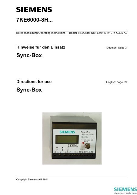
<strong>7KE6000</strong>-<strong>8H</strong>...<br />
Betriebsanleitung/Operating Instructions Bestell-Nr./Order No.: E50417-K1074-C305-A2<br />
Hinweise für den Einsatz Deutsch: Seite 3<br />
<strong>Sync</strong>-<strong>Box</strong><br />
Directions for use English: page 39<br />
<strong>Sync</strong>-<strong>Box</strong><br />
Copyright <strong>Siemens</strong> AG 2011
Haftungsausschluss<br />
Wir haben den Inhalt der Druckschrift auf Übereinstimmung mit der<br />
beschriebenen Hard- und Software geprüft. Dennoch können Abweichungen<br />
nicht ausgeschlossen werden, sodass wir für die vollständige<br />
Übereinstimmung keine Gewähr übernehmen.<br />
Die Angaben in dieser Betriebsanleitung werden regelmäßig überprüft,<br />
und notwendige Korrekturen sind in den nachfolgenden Auflagen<br />
enthalten. Für Verbesserungsvorschläge sind wir dankbar.<br />
Technische Änderungen bleiben, auch ohne Ankündigung, vorbehalten.<br />
Ausgabe: 1.00.05<br />
Liability Statement<br />
Although we have carefully checked the contents of this publication<br />
for conformity with the hardware and software described, we cannot<br />
guarantee complete conformity since errors cannot be excluded.<br />
The information provided in these operating instructions is checked<br />
at regular intervals and any corrections that might become necessary<br />
are included in the next releases. Any suggestions for improvement<br />
are welcome.<br />
Subject to change without prior notice. Release: 1.00.05<br />
Copyright<br />
Copyright © <strong>Siemens</strong> AG 2011 All Rights Reserved<br />
Weitergabe und Vervielfältigung dieser Unterlage, Verwertung und<br />
Mitteilung ihres Inhalts ist nicht gestattet, soweit nicht ausdrücklich<br />
zugestanden. Zuwiderhandlungen verpflichten zu Schadenersatz.<br />
Alle Rechte vorbehalten, insbesondere für den Fall der Patenterteilung<br />
oder GM-Eintragung.<br />
Eingetragene Marken<br />
SIPROTEC ® , SIMEAS R ® , SIMATIC ® und OSCOP P ® sind eingetragene<br />
Marken der SIEMENS AG. Die übrigen Bezeichnungen in<br />
dieser Betriebsanleitung können Marken sein, deren Benutzung<br />
durch Dritte für deren Zwecke die Rechte der Inhaber verletzen<br />
können.<br />
Copyright<br />
Copyright © <strong>Siemens</strong> AG 2011 All Rights Reserved<br />
The reproduction, transmission or use of this document or its contents<br />
is not permitted without express written authority. Offenders<br />
will be liable for damages. All rights, including rights created by<br />
patent grant or registration of a utility model or design, are reserved.<br />
Registered Trademarks<br />
SIPROTEC ® , SIMEAS R ® , SIMATIC ® and OSCOP P ® are registered<br />
trademarks of SIEMENS AG. All other product and brand<br />
names in these operating instructions might be trademarks, the use<br />
of which by third persons for their purposes might infringe the rights<br />
of their respective owners.<br />
<strong>Sync</strong>-<strong>Box</strong><br />
2 E50417-K1074-C305-A2
<strong>Sync</strong>-<strong>Box</strong> Deutsch<br />
Inhalt<br />
Angaben zur Konformität ................................................................................................... 4<br />
Hinweise zu Ihrer Sicherheit .............................................................................................. 5<br />
Allgemeine Hinweise .......................................................................................................... 9<br />
Aus- und Einpacken des Gerätes .................................................................................... 10<br />
Lagerung und Transport ................................................................................................... 10<br />
Verwendung ..................................................................................................................... 11<br />
Merkmale ......................................................................................................................... 11<br />
Funktion ........................................................................................................................... 12<br />
Anschlüsse ....................................................................................................................... 13<br />
Bedienung ........................................................................................................................ 14<br />
Parametrierung ................................................................................................................ 15<br />
Anschlusshinweise ........................................................................................................... 15<br />
Montage ........................................................................................................................... 17<br />
Inbetriebsetzung ............................................................................................................... 18<br />
Technische Daten ............................................................................................................ 19<br />
Maßbilder ......................................................................................................................... 23<br />
Bestellhinweise ................................................................................................................ 24<br />
Wartung, Instandsetzung und Reinigung ......................................................................... 25<br />
Anhang ............................................................................................................................. 26<br />
DCF77-Antenne mit Empfänger <strong>7KE6000</strong>-8AQ ............................................................... 33<br />
Kontaktadresse ................................................................................................................ 76<br />
E50417-K1074-C305-A2 3
Deutsch <strong>Sync</strong>-<strong>Box</strong><br />
Angaben zur Konformität<br />
Das Produkt entspricht den Bestimmungen der Richtlinie des Rates der Europäischen<br />
Gemeinschaften zur Angleichung der Rechtsvorschriften der Mitgliedsstaaten über die<br />
elektromagnetische Verträglichkeit (EMV-Richtlinie 89/336/EWG) und betreffend elektrische<br />
Betriebsmittel zur Verwendung innerhalb bestimmter Spannungsgrenzen<br />
(Niederspannunsrichtlinie 73/23/EWG).<br />
Diese Konformität ist das Ergebnis einer Prüfung, die durch die <strong>Siemens</strong> AG gemäß<br />
Artikel 10 der Richtlinie in Übereinstimmung mit den Fachgrundnormen EN 61000-6-4 und<br />
EN 61000-6-2 für die EMV-Richtlinie und der Norm EN 61010-1 für die Niederspannungsrichtlinie<br />
durchgeführt worden ist.<br />
Das Gerät ist für den Einsatz im Industriebereich gemäß der Norm EN 61000-6-4 entwickelt<br />
und hergestellt.<br />
4 E50417-K1074-C305-A2
<strong>Sync</strong>-<strong>Box</strong> Deutsch<br />
Hinweise zu Ihrer Sicherheit<br />
Dieses Handbuch stellt kein vollständiges Verzeichnis aller für einen Betrieb des Betriebsmittels<br />
(Baugruppe, Gerät) erforderlichen Sicherheitsmaßnahmen dar, weil besondere<br />
Betriebsbedingungen weitere Maßnahmen erforderlich machen können. Es enthält jedoch<br />
Hinweise, die Sie zu Ihrer persönlichen Sicherheit sowie zur Vermeidung von Sachschäden<br />
beachten müssen. Die Hinweise sind durch ein Warndreieck hervorgehoben und je nach<br />
Gefährdungsgrad wie folgt dargestellt:<br />
GEFAHR<br />
GEFAHR bedeutet, dass Tod oder schwere Verletzungen eintreten<br />
werden, wenn die angegebenen Maßnahmen nicht getroffen werden.<br />
Beachten Sie alle Hinweise, um Tod oder schwere Verletzungen zu<br />
vermeiden.<br />
WARNUNG<br />
WARNUNG bedeutet, dass Tod oder schwere Ververletzungen eintreten<br />
können, wenn die angegebenen Maßnahmen nicht getroffen<br />
werden.<br />
Beachten Sie alle Hinweise, um Tod oder schwere Verletzungen zu<br />
vermeiden.<br />
VORSICHT<br />
VORSICHT bedeutet, dass mittelschwere oder leichte Ververletzungen<br />
eintreten können, wenn die angegebenen Maßnahmen nicht getroffen<br />
werden.<br />
Beachten Sie alle Hinweise, um mittelschwere oder leichte Verletzungen<br />
zu vermeiden.<br />
ACHTUNG<br />
ACHTUNG bedeutet, dass Sachschäden entstehen können, wenn die<br />
angegebenen Maßnahmen nicht getroffen werden.<br />
Beachten Sie alle Hinweise, um Sachschäden zu vermeiden.<br />
Hinweis<br />
ist eine wichtige Information über das Produkt, die Handhabung des<br />
Produktes oder den jeweiligen Teil der Dokumentation, auf den besonders<br />
aufmerksam gemacht werden soll.<br />
E50417-K1074-C305-A2 5
Deutsch <strong>Sync</strong>-<strong>Box</strong><br />
VORSICHT<br />
Vorsicht vor spannungsführenden Teilen.<br />
Bei Nichtbeachtung der Sicherheitsvorschriften können leichte<br />
oder mittelschwere Verletzungen eintreten.<br />
Die Geräte <strong>7KE6000</strong> sind Einbaugeräte und somit in einem<br />
Schaltschrank oder Verteilerkasten einzubauen. Nach dem Einbau<br />
muss der gesamte Klemmenbereich abgedeckt sein. Nur so ist das<br />
Gerät ausreichend gegen unzulässiges Berühren spannungsführender<br />
Teile geschützt.<br />
WARNUNG<br />
Warnung beim Betrieb elektrischer Geräte stehen zwangsläufig bestimmte<br />
Teile dieser Geräte unter gefährlicher Spannung.<br />
Die Nichtbeachtung der Sicherheitsvorschriften können Tod oder<br />
schwere Verletzungen zur Folge haben.<br />
Nur entsprechend qualifiziertes Personal soll an diesem Gerät oder<br />
in dessen Nähe arbeiten. Dieses Personal muss gründlich mit allen<br />
Warnungen und Instandhaltungsmaßnahmen gemäß dieser Betriebsanleitung<br />
sowie mit den Sicherheitsvorschriften vertraut sein.<br />
Der einwandfreie und sichere Betrieb des Gerätes setzt sachgemäßen<br />
Transport, fachgerechte Lagerung, Aufstellung und Montage,<br />
sowie sorgfältige Bedienung und Instandhaltung unter Beachtung<br />
der Warnungen und Hinweise dieser Betriebsanleitung voraus.<br />
Insbesondere sind die Allgemeinen Errichtungs- und Sicherheitsvorschriften<br />
für das Arbeiten an Starkstromanlagen (z.B. DIN, VDE, EN,<br />
IEC oder andere nationale und internationale Vorschriften) zu<br />
beachten.<br />
6 E50417-K1074-C305-A2
<strong>Sync</strong>-<strong>Box</strong> Deutsch<br />
Qualifiziertes Personal<br />
Inbetriebsetzung und Betrieb eines in diesem Handbuch beschriebenen<br />
Betriebsmittels (Baugruppe, Gerät) dürfen nur von qualifiziertem Personal<br />
vorgenommen werden. Qualifiziertes Personal im Sinne der<br />
sicherheitstechnischen Hinweise dieses Handbuches sind Personen,<br />
die die Berechtigung haben, Geräte, Systeme und Stromkreise gemäß<br />
den Standards der Sicherheitstechnik in Betrieb zu nehmen, freizuschalten,<br />
zu erden und zu kennzeichnen.<br />
Bestimmungsgemäßer Gebrauch<br />
Das Betriebsmittel (Gerät, Baugruppe) darf nur für die im Katalog und<br />
der technischen Beschreibung vorgesehenen Einsatzfälle und nur in<br />
Verbindung mit von <strong>Siemens</strong> empfohlenen bzw. zugelassenen Fremdgeräten<br />
und -komponenten verwendet werden.<br />
Der einwandfreie und sichere Betrieb des Produktes setzt sachgemäßen<br />
Transport, sachgemäße Lagerung, Aufstellung und Montage<br />
sowie Bedienung und Instandhaltung voraus.<br />
Beim Betrieb elektrischer Betriebsmittel stehen zwangsläufig bestimmte<br />
Teile dieser Betriebsmittel unter gefährlicher Spannung. Es können<br />
deshalb schwere Körperverletzung oder Sachschäden auftreten, wenn<br />
nicht fachgerecht gehandelt wird:<br />
Vor Anschluss irgendwelcher Verbindungen ist das Betriebsmittel<br />
am Schutzleiteranschluss zu erden.<br />
Gefährliche Spannungen können in allen mit der Spannungsversorgung<br />
verbundenen Schaltungsteilen anstehen.<br />
Auch nach Abtrennen der Versorgungsspannung können gefährliche<br />
Spannungen im Betriebsmittel vorhanden sein (Kondensatorspeicher).<br />
Betriebsmittel mit Stromwandlerkreisen dürfen nicht offen betrieben<br />
werden.<br />
Die im Handbuch bzw. in der Betriebsanleitung genannten Grenzwerte<br />
dürfen nicht überschritten werden; dies ist auch bei der Prüfung<br />
und der Inbetriebnahme zu beachten.<br />
E50417-K1074-C305-A2 7
Deutsch <strong>Sync</strong>-<strong>Box</strong><br />
VORSICHT<br />
Vorsicht bei der Batterie-Entsorgung.<br />
Bei Nichtbeachtung der Sicherheitsvorschriften können leichte<br />
oder mittelschwere Verletzungen eintreten.<br />
Die im Gerät befindliche Batterie darf nur durch Fachpersonal ausgetauscht<br />
werden.<br />
Bei unsachgemäßem Austausch besteht Explosionsgefahr.<br />
Batterien dürfen nur durch den gleichen oder vom Hersteller empfohlenen<br />
Typ ersetzt werden.<br />
Bei der Entsorgung der Batterien sind die örtlichen nationalen/internationalen<br />
Bestimmungen zu beachten.<br />
8 E50417-K1074-C305-A2
<strong>Sync</strong>-<strong>Box</strong> Deutsch<br />
Allgemeine Hinweise<br />
Diese Betriebsanleitung ist fester Bestandteil des Lieferumfangs. Sie enthält aus Gründen<br />
der Übersichtlichkeit nicht sämtliche Details zu allen Ausführungen des beschriebenen<br />
Produkts und kann auch nicht jeden denkbaren Fall der Aufstellung, des Betriebes oder der<br />
Instandhaltung berücksichtigen. Sollten Sie weitere Informationen wünschen, oder sollten<br />
besondere Probleme auftreten, die in dieser Unterlage nicht ausführlich genug behandelt<br />
werden, dann fordern Sie bitte die benötigte Auskunft von Ihrer örtlichen <strong>Siemens</strong>-Niederlassung<br />
an, oder wenden Sie sich direkt an unsere Kontaktadresse (siehe Seite 76).<br />
Außerdem weisen wir darauf hin, dass der Inhalt dieser Produktdokumentation nicht Teil<br />
einer früheren oder bestehenden Vereinbarung, Zusage oder eines Rechtsverhältnisses ist<br />
oder dieses abändern soll. Sämtliche Verpflichtungen von <strong>Siemens</strong> ergeben sich aus dem<br />
jeweiligen Kaufvertrag, der auch die vollständige und allein gültige Gewährleistungsregelung<br />
enthält. Diese vertraglichen Gewährleistungsbestimmungen werden auch durch die<br />
Ausführungen in dieser Unterlage weder erweitert noch beschränkt.<br />
E50417-K1074-C305-A2 9
Deutsch <strong>Sync</strong>-<strong>Box</strong><br />
Aus- und Einpacken des Gerätes<br />
Die Geräte werden im Werk so verpackt, dass sie die Anforderungen nach IEC 60255-21<br />
erfüllen.<br />
Das Aus- und Einpacken ist mit der üblichen Sorgfalt ohne Gewaltanwendung und nur unter<br />
Verwendung von geeignetem Werkzeug vorzunehmen. Die Geräte sind durch Sichtkontrolle<br />
auf einwandfreien mechanischen Zustand zu überprüfen.<br />
Bitte beachten Sie evtl. weitere beigelegte Hinweise.<br />
Die Transportverpackung kann bei Weiterversand in gleicher Weise wiederverwendet werden.<br />
Die Lagerverpackung der Einzelgeräte ist nicht für Transport ausreichend. Bei Verwendung<br />
anderer Verpackungen muss das Einhalten der Transportanforderungen entsprechend<br />
IEC 60255-21-1 Klasse 2 und IEC 60255-21-2 Klasse 1 sichergestellt werden.<br />
Bevor das Gerät erstmalig an Spannung gelegt wird, muss es mindestens 2 Stunden im<br />
Betriebsraum gelegen haben, um einen Temperaturausgleich zu schaffen und Feuchtigkeit<br />
und Betauung zu vermeiden.<br />
Lagerung und Transport<br />
SIMEAS-Geräte und deren Zubehör sollen in trockenen und sauberen Räumen gelagert<br />
werden. Für die Lagerung des Gerätes oder zugehöriger Ersatzbaugruppen gilt der Temperaturbereich<br />
von -25 °C bis +55 °C.<br />
Die relative Feuchte darf weder zur Kondenswasser- noch zur Eisbildung führen.<br />
Es wird empfohlen, bei der Lagerung einen eingeschränkten Temperaturbereich zwischen<br />
+10 °C und +35 °C einzuhalten, um einer vorzeitigen Alterung der in der Stromversorgung<br />
eingesetzten Elektrolytkondensatoren vorzubeugen.<br />
Außerdem empfiehlt es sich bei langer Lagerungszeit, das Gerät etwa alle 2 Jahre für 1 bis<br />
2 Tage an Hilfsspannung zu legen, um die in der Stromversorgung eingesetzten Elektrolytkondensatoren<br />
zu formieren. Ebenso sollte vor einem geplanten Einsatz des Gerätes<br />
verfahren werden.<br />
Hinweis<br />
Die Lithium Batterien der Geräte erfüllen die internationalen Voraussetzungen<br />
der Gefahrgutvorschriften für die verschiedenen Verkehrsträger<br />
(Sonderbestimmung 188 aus den UN Empfehlungen für den<br />
Transport gefährlicher Güter, Sonderbestimmung A45 der IATA Gefahrgutvorschrift<br />
und den technischen Anleitungen der ICAO). Dies gilt nur<br />
für die Originalbatterie oder Original-Ersatzbatterien.<br />
10 E50417-K1074-C305-A2
<strong>Sync</strong>-<strong>Box</strong> Deutsch<br />
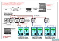
Verwendung<br />
Es gibt mehrere Normalzeitsysteme auf der Welt, die Zeit und Datum aussenden. Dazu eine<br />
große Anzahl von Empfängersystemen, die meist ein unterschiedliches Ausgabeformat<br />
haben.<br />
Da es aufwändig und nicht vertretbar ist, alle nötigen Umsetzfunktionen im DAKON oder im<br />
SIMEAS R zu implementieren und bei Bedarf zu ergänzen, ist dafür ein externes Gerät<br />
vorgesehen. Dieses externe Gerät, die <strong>Sync</strong>-<strong>Box</strong>, kann einfach an die unterschiedlichen<br />
Systeme angepasst werden und gibt zur Zeitsynchronisierung des SIMEAS R ein immer<br />
gleiches Impulstelegramm ab.<br />
Das Telegrammformat ist ein geringfügig modifizierter DCF77-Code. Über eine serielle<br />
Schnittstelle kann zusätzlich ein DAKON synchronisiert werden.<br />
Merkmale<br />
Die <strong>Sync</strong>hronisiereinheit (<strong>Sync</strong>-<strong>Box</strong>) ist eine festverdrahtete und geprüfte Funktionseinheit.<br />
Sie besitzt eine Schnappbefestigung für eine Hutschiene 35 mm nach DIN EN 50022. An<br />
den Schraubklemmen lässt sich die Hilfsenergie sicher anschließen.<br />
Für den Eingang der Zeitinformation wird je nach Ausführung entweder:<br />
die BNC-Buchse auf der Gerätefront oder<br />
die serielle Schnittstelle 1 (Klemme 11/12/13) benutzt.<br />
Der Anschluss an den SIMEAS R erfolgt über dessen Steuereingang 1 der CPU (<strong>Sync</strong>hronisation,<br />
Anschlussklemmen 7B1(+) und 7B2(-)) und über die Klemmen 9 und 10 an der<br />
<strong>Sync</strong>-<strong>Box</strong>.<br />
Hinweis<br />
Der Steuereingang 1 muss als 24-V-Eingang am SIMEAS R ausgeführt<br />
sein!<br />
Die zweite serielle Schnittstelle (Klemme 14/15/16) stellt ein Zeittelegramm zur <strong>Sync</strong>hronisierung<br />
eines DAKON-PC zur Verfügung.<br />
An den Klemmen 5, 6 und 7 stellt die <strong>Sync</strong>-<strong>Box</strong> an einem potentialfreien elektronischen<br />
Kontakt einen Minutenimpuls zur <strong>Sync</strong>hronisierung anderer Geräte zur Verfügung.<br />
Die <strong>Sync</strong>-<strong>Box</strong> zeigt die aktuelle Zeit sowie den Empfangsstatus des Zeitzeichensignals im<br />
Display an.<br />
Hinweis<br />
Erläuterungen zu den einzelnen unterstützten Zeitzeichensignalen finden<br />
Sie im Anhang, Seite 26.<br />
E50417-K1074-C305-A2 11
Deutsch <strong>Sync</strong>-<strong>Box</strong><br />
Funktion<br />
Bild 1 Blockschaltbild der <strong>Sync</strong>-<strong>Box</strong><br />
Abbildung 1 skizziert die Funktionalität der <strong>Sync</strong>-<strong>Box</strong>. Die <strong>Sync</strong>-<strong>Box</strong> besitzt drei Ausgänge,<br />
mit denen aus einem Zeitzeichensignal die unterschiedlichsten Geräte synchronisiert werden<br />
können.<br />
Eigenschaften<br />
Variable Zeitzeicheneingänge<br />
Modifizierter DCF77 Zeitzeichenausgang (SIMEAS R)<br />
Minutenimpulsausgang<br />
Serielles Zeittelegramm zum <strong>Sync</strong>hronisieren von DAKONs<br />
Anzeige der aktuellen Uhrzeit im Display<br />
Setzen der Uhrzeit durch Taster<br />
12 E50417-K1074-C305-A2
<strong>Sync</strong>-<strong>Box</strong> Deutsch<br />
Anschlüsse<br />
Bild 2 Belegung der Anschlussklemmen<br />
Versorgungsspannung<br />
+L Hilfsenergie gemäß Bestellvariante (siehe Seite 24)<br />
-L<br />
Minutenimpuls (<strong>Sync</strong>-Output B)<br />
5 +/~ Ausgang<br />
6 - Ausgang<br />
7 ~ Ausgang<br />
SIMEAS R - <strong>Sync</strong> Out (<strong>Sync</strong>-Output A)<br />
9 Gnd Out (SIMEAS R Zeiteingang 24V [-] Klemme 7B2)<br />
10 + 24 V Out (SIMEAS R Zeiteingang 24V [+] Klemme 7B1)<br />
Zeitzeicheneingang 1 (HF-Eingang)<br />
SYNC-IN BNC - Buchse<br />
Zeitzeicheneingang 2 (serielle Schnittstelle 1, RS232)<br />
11 RxD<br />
12 TxD<br />
13 GND<br />
E50417-K1074-C305-A2 13
Deutsch <strong>Sync</strong>-<strong>Box</strong><br />
Zeitzeichenausgang DAKON (serielle Schnittstelle 2, RS232, <strong>Sync</strong>-Output C)<br />
14 RxD<br />
15 TxD<br />
16 GND<br />
Bedienung<br />
Nach Inbetriebnahme wird immer Stunde und Minute mit einem Doppelpunkt getrennt,<br />
welcher im Sekundenrhythmus blinkt, angezeigt. Bei ordnungsgemäßem Empfang von<br />
DCF77 oder einer anderen Zeitbasis wird nach ca. 3 Minuten die empfangene Zeitinformation<br />
übernommen. Dies erkennt man, indem anstelle des Doppelpunktes drei Punkte im<br />
Sekundentakt blinken. Hinter drei Bohrungen in der Frontplatte sind Mikroschalter so<br />
angebracht, dass sie mit der Spitze eines Kugelschreibers oder ähnlichem betätigt werden<br />
können. Diese sind mit folgenden Symbolen gekennzeichnet:<br />
S Mit den beiden Pfeiltasten kann die Anzeige auf<br />
Stunde : Minute 18:23<br />
Minute : Sekunde 23:58<br />
Jahr 19 97<br />
Tag : Monat 12.06<br />
vor und zurückgeschaltet werden. Wird die Taste "S" gedrückt, zeigt die Anzeige das Jahr<br />
an und blinkt. In dieser Betriebsart können in folgender Reihenfolge Jahr, Monat, Tag,<br />
Stunde, Minute und Sekunde mit den beiden Pfeiltasten verstellt werden. Das Umschalten<br />
zwischen den einzelnen Eingabefeldern erfolgt immer durch weiteres Drücken der "S"<br />
Taste. Durch kurzes Drücken auf eine Pfeiltaste wird der zugehörige Wert um eine Einheit<br />
höher oder zurück gestellt. Wird länger als eine Sekunde ununterbrochen gedrückt, dann<br />
erfolgt das Hochzählen mit einem Takt von 5 Schritten pro Sekunde.<br />
Befindet sich die <strong>Sync</strong>hronisiereinheit im Eingabemodus, der durch das Blinken der Anzeige<br />
erkennbar ist, müssen immer alle Eingabefelder eingegeben bzw. weitergeschaltet werden.<br />
Im Gerät ist ein batteriegepufferter Uhrenschaltkreis enthalten, welcher Datum und Zeit auch<br />
bei Spannungsausfall mit geringer Abweichung weiterführt. Diese Uhr wird vom Prozessor<br />
millisekundengenau mit dem empfangenen Zeitsignal synchronisiert.<br />
Solange die Hilfsspannung ansteht, läuft der Prozessor und setzt die Zeitinformation der Uhr<br />
in die zugehörige DCF77-Impulsfolge um. Diese wird als Signal mit 24 Volt abgegeben. Bei<br />
ordnungsgemäßem Empfang des Zeitsignals wird die Uhr im Minutentakt synchronisiert. Bei<br />
<strong>Sync</strong>hronität ist das abgegebene Impulsbild für Zeit und Datum fast identisch mit dem<br />
empfangenen. Diese Impulsfolge wird auch dann erzeugt, wenn ein anderes Zeitnormal als<br />
DCF77 benutzt wird.<br />
Solange ordnungsgemäßer Empfang der Normalzeit nicht möglich ist, gleichgültig um<br />
welches System es sich handelt, wird in dem Impulstelegramm ein Störungsbit gesetzt, das<br />
diesen Zustand kennzeichnet. Dazu dient das Bit 15, welches im Originaltelegramm den<br />
Betrieb der Hilfsantenne markiert.<br />
14 E50417-K1074-C305-A2
<strong>Sync</strong>-<strong>Box</strong> Deutsch<br />
Parametrierung<br />
Der Auslieferungszustand der <strong>Sync</strong>-<strong>Box</strong> ist gemäß der bestellten Variante (MLFB). Eine<br />
weitere Parametrierung der <strong>Sync</strong>-<strong>Box</strong> ist nicht notwendig.<br />
Sollten dennoch Modifikationen benötigt werden, kontaktieren Sie bitte unseren Customer<br />
Support Service (siehe Kontaktadresse, Seite 76).<br />
Anschlusshinweise<br />
Hilfsenergieanschluss und Signalleitungen<br />
Direktanschluss: Massivleiter oder Litzenleiter mit Aderendhülse für Leitungsquerschnitte<br />
von 0,5 mm 2 bis 2,5 mm 2 (entsprechend AWG 22 bis 12).<br />
Die Spannungsfestigkeit aller Anschlussleitungen (Hilfsenergieanschluss und Signaleinund<br />
-ausgänge) muss min. 300 V AC betragen. Drehmoment: min 0,5 Nm.<br />
Der maximale Nennstrom des Gerätes beträgt 0,5 A. Um eine ausreichende Selektivität in<br />
der Sicherungskette zu gewährleisten, sollte der vorgeschaltete Leitungsschutzschalter<br />
mindestens 2 A betragen. Der Maximalwert ist in Abhängigkeit der Schrankverdrahtung zu<br />
wählen. Der Leitungsschutzschalter muss nahe des Gerätes montiert und entsprechend<br />
beschriftet sein.<br />
Für die serielle Schnittstelle 1 (Klemmen11/12/13) und die serielle Schnittstelle 2 (Klemmen<br />
14/15/16) sind geschirmte Leitungen zu verwenden.<br />
Sollten die Leitungen an <strong>Sync</strong>-Output A (Klemmen 9/10) oder <strong>Sync</strong>-Output B (Klemmen<br />
5/6/7) den Einbauschrank verlassen, sind hier ebenfalls geschirmte Leitungen zu verwenden.<br />
E50417-K1074-C305-A2 15
Deutsch <strong>Sync</strong>-<strong>Box</strong><br />
Anschlussbeispiel (DCF-Antenne)<br />
Bild 3 Anschlussbeispiel (DCF-Antenne)<br />
16 E50417-K1074-C305-A2
<strong>Sync</strong>-<strong>Box</strong> Deutsch<br />
Montage<br />
Einbau<br />
WARNUNG<br />
Warnung vor gefährlicher Spannung.<br />
Die Nichtbeachtung der Sicherheitsvorschriften können Tod oder<br />
schwere Verletzungen zur Folge haben.<br />
Beim Betrieb elektrischer Geräte stehen zwangsläufig bestimmte<br />
Teile dieser Geräte unter gefährlicher Spannung.<br />
Montage und elektrischer Anschluss des Geräts dürfen nur durch<br />
entsprechend qualifiziertes Personal vorgenommen werden.<br />
Insbesondere müssen alle Warnhinweise unbedingt beachtet werden.<br />
Die Einbaustelle soll möglichst erschütterungsfrei sein.<br />
Die zulässige Umgebungstemperatur (Arbeits- bzw. Funktionstemperatur) muss eingehalten<br />
werden (siehe Technische Daten).<br />
Der Betrieb außerhalb des Funktionstemperaturbereichs kann zu Funktionsstörungen<br />
und zum Ausfall der <strong>Sync</strong>-<strong>Box</strong> führen.<br />
Die <strong>Sync</strong>-<strong>Box</strong> lässt sich auf eine 35 mm Hutschiene (nach DIN EN 50022) aufschnappen.<br />
Anschluss<br />
Bei der elektrischen Installation sind die Vorschriften über das Errichten von Starkstromanlagen<br />
zu beachten.<br />
E50417-K1074-C305-A2 17
Deutsch <strong>Sync</strong>-<strong>Box</strong><br />
Inbetriebsetzung<br />
Prüfen Sie, ob die Betriebsdaten mit den Werten auf dem Typenschild übereinstimmen.<br />
Nehmen Sie an der <strong>Sync</strong>-<strong>Box</strong> keine Veränderungen vor.<br />
Schnappen Sie die <strong>Sync</strong>-<strong>Box</strong> mittels der Gehäuseschnappbefestigung auf eine Hutschiene<br />
auf.<br />
Schließen Sie die gewünschten Signalein- und -ausgänge an.<br />
Schließen Sie die Hilfsenergie an Klemme +L und -L an.<br />
Schalten Sie die Hilfsenergieversorgung der <strong>Sync</strong>-<strong>Box</strong> erst nach Anschluss des <strong>Sync</strong>-<br />
Signals und der gewünschten Signalausgänge zu.<br />
Nach Zuschalten der Hilfsenergie ist die <strong>Sync</strong>-<strong>Box</strong> betriebsbereit.<br />
Bei ordnungsgemäßem Empfang des entsprechenden Zeitzeichensignals ist die<br />
<strong>Sync</strong>-<strong>Box</strong> nach ca. 3 Minuten synchronisiert.<br />
18 E50417-K1074-C305-A2
<strong>Sync</strong>-<strong>Box</strong> Deutsch<br />
Technische Daten<br />
Hilfsenergie U H<br />
Nennhilfsspannung U HN<br />
- Niedervoltvariante (siehe Bestellhinweis)<br />
Gleichspannung DC 24 V bis 60 V<br />
- Hochvoltvariante (siehe Bestellhinweis)<br />
Gleichspannung DC 110 V bis 250 V<br />
Wechselspannung AC 115 V bis 230 V; 45 Hz bis 65 Hz<br />
Eingangsbereich<br />
Gleichspannung ±20 %<br />
Wechselspannung ±20 %<br />
Leistungsaufnahme<br />
Gleichspannung 1 W<br />
Wechselspannung 4 VA<br />
vorzuschaltende Sicherung T 2 A/250 V AC und 250 V DC<br />
nach IEC 60127<br />
Signaleingänge<br />
- HF-Eingang<br />
(siehe Bestellhinweis)<br />
BNC-Buchse SYNC.-IN<br />
Anzahl der Anschlüsse<br />
- Serielle Schnittstelle 1<br />
1<br />
Klemmen 11/12/13<br />
Anzahl der Anschlüsse<br />
Signalausgänge<br />
- SIMEAS R - <strong>Sync</strong> Out<br />
3 (RS232-Signal)<br />
Klemmen 9/10<br />
Anzahl der Anschlüsse 2 (PWM-Signal 24 V)<br />
- Minutenimpulsausgang (photoMOS-relay)<br />
Klemmen 5/6/7<br />
Anzahl der Anschlüsse 3 (potentialfrei)<br />
max. 250 V, max. 100 mA<br />
RDSON - Serielle Schnittstelle 2<br />
max. 35 Ω<br />
Klemmen 14/15/16<br />
Anzahl der Anschlüsse 3 (RS232-Signal)<br />
E50417-K1074-C305-A2 19
Deutsch <strong>Sync</strong>-<strong>Box</strong><br />
Sicherheit<br />
nach IEC/EN 61010, Teil 1<br />
(VDE 0411 Teil 1)<br />
Überspannungskategorie III<br />
Verschmutzungsgrad 2<br />
Brandbeständigkeitsklasse des Gehäuses V0 nach UL94<br />
Spannungsprüfungen (Typprüfung)<br />
Klemmen 5 bis 16 und BNC-Buchse<br />
gegen Hilfsspannung U = 5,2 kV DC / 1 min<br />
Klemmen 5/6/7<br />
gegen 8 bis 16 und BNC-Buchse U = 5,2 kV DC / 1 min<br />
Stoßspannung nach IEC 60255-5 (Typprüfung) 5 kV<br />
Spannungsprüfung (Stückprüfung)<br />
Klemmen 5 bis 16 und BNC-Buchse<br />
gegen Hilfsspannung U = 3,1 kV DC / 2 s<br />
Klemmen 5/6/7<br />
gegen 8 bis 16 und BNC-Buchse U = 3,1 kV DC / 2 s<br />
Schutzart<br />
für das Betriebsmittel IP 40<br />
für den Personenschutz IP 2x<br />
WARNUNG<br />
Warnung vor spannungführenden Teilen.<br />
Die Nichtbeachtung der Sicherheitsvorschriften können Tod oder<br />
schwere Verletzungen zur Folge haben.<br />
Die Geräte <strong>7KE6000</strong> sind Einbaugeräte und somit in einem<br />
Schaltschrank oder Verteilerkasten einzubauen. Nach dem Einbau<br />
muss der gesamte Klemmenbereich abgedeckt sein. Nur so ist das<br />
Gerät ausreichend gegen unzulässiges Berühren spannungsführender<br />
Teile geschützt.<br />
Isolation der Ein- und Ausgänge<br />
Stromversorgung gegen Ein- und Ausgänge doppelte bzw. verstärkte Isolation<br />
Klemmen 5/6/7 gegen<br />
Klemme 8 bis 16 und BNC-Buchse doppelte bzw. verstärkte Isolation<br />
20 E50417-K1074-C305-A2
<strong>Sync</strong>-<strong>Box</strong> Deutsch<br />
Elektromagnetische Verträglichkeit<br />
Störaussendung nach IEC/EN 61000-6-4<br />
Funkstörfeldstärke nach EN55011/CISPR11 Klasse A<br />
Funkstörspannung nach EN55011/CISPR11 Klasse A<br />
Störfestigkeit nach IEC/EN 61000-6-2<br />
Störfestigkeit gegen elektromagnetische<br />
Felder nach IEC/EN 61000-4-3 10 V/m<br />
Entladung statischer Elektrizität ESD<br />
nach IEC/EN 61000-4-2 8 kV<br />
Schnelle Transienten/Burst<br />
nach IEC/EN 61000-4-4 2 kV<br />
HF-Bestromung nach IEC/EN 61000-4-6 10 V<br />
Stoßspannung/Surge nach IEC/EN 61000-4-5 1/2 kV<br />
Mechanische Prüfungen<br />
Schwing- und Schockbeanspruchung IEC 60255-21 und IEC 60068<br />
bei stationärem Einsatz<br />
- Schwingung IEC 60255-21-1, Klasse 2,<br />
IEC 60068-2-6<br />
- Schock IEC 60255-21-2, Klasse 1,<br />
IEC 60068-2-27<br />
- Schwingung bei Erdbeben IEC 60255-21-3, Klasse 1,<br />
IEC 60068-3-3<br />
Schwing- und Schockbeanspruchung IEC 60255-21 und IEC 60068<br />
beim Transport<br />
- Schwingung IEC 60255-21-1, Klasse 2,<br />
IEC 60068-2-6<br />
- Schock IEC 60255-21-2, Klasse 1,<br />
IEC 60068-2-27<br />
- Dauerschock IEC 60255-21-2, Klasse 1,<br />
IEC 60068-2-29<br />
Temperaturen IEC 60688<br />
- empfohlene Temperatur bei Betrieb -5 °C bis +55 °C<br />
- Grenztemperaturen bei Lagerung -25 °C bis +55 °C<br />
- Grenztemperaturen bei Transport -25 °C bis +70 °C<br />
Lagerung und Transport mit werksmäßiger Verpackung!<br />
E50417-K1074-C305-A2 21
Deutsch <strong>Sync</strong>-<strong>Box</strong><br />
Feuchte<br />
Maximale relative Luftfeuchte 80 % bei Temperaturen bis zu 31 °C,<br />
linear abnehmend bis zu 50 % bei 40 °C<br />
Einsatzhöhe<br />
Maximale Höhe über dem 2000 m<br />
Meeresspiegel<br />
Die Geräte sind so anzuordnen, dass sie keiner direkten Sonneneinstrahlung und keinem<br />
starken Temperaturwechsel, bei dem Betauung auftreten kann, ausgesetzt sind.<br />
22 E50417-K1074-C305-A2
<strong>Sync</strong>-<strong>Box</strong> Deutsch<br />
Maßbilder<br />
Bild 4 Maßbilder der <strong>Sync</strong>-<strong>Box</strong> (Alle Maße in mm)<br />
E50417-K1074-C305-A2 23
Deutsch <strong>Sync</strong>-<strong>Box</strong><br />
Bestellhinweise<br />
Beschreibung Bestellnummer<br />
Zeitsynchronisiereinheit *) <strong>7KE6000</strong>-<strong>8H</strong>A<br />
im Gehäuse mit Schnappbefestigung | |<br />
für Hutschiene 35 mm nach DIN EN 500 022 | |<br />
mit Anschlusskabel für SIMEAS R und DAKON PC | |<br />
| |<br />
Empfänger-/Dekoderbaugruppe für Zeitsynchronisierung | |<br />
| |<br />
Anschluss über BNC-Stecker: | |<br />
| |<br />
• DCF77-Empfänger für den Einsatz mit der Antenne <strong>7KE6000</strong>-8AQ 1 |<br />
Antenne <strong>7KE6000</strong>-8AQ ist getrennt zu bestellen | |<br />
Diese Lösung ist nur dann möglich wenn das DCF 77 Signal direkt | |<br />
empfangen werden kann | |<br />
| |<br />
• Dekoder für DCF 77-Signal 2 |<br />
Zum Beispiel zum Anschluss an einen HOPF 6870 GPS Empfänger | |<br />
(Diese Konfiguration wird empfohlen!) | |<br />
| |<br />
• Dekoder für Patek-Philippe-Signal 4 |<br />
• Dekoder für IRIG B-Signal (z.B. von GPS-Empfänger)1) 5 |<br />
• Dekoder für Telenorma-Signal 6 |<br />
• Dekoder für demoduliertes IRIG B-Signal, TTL-Pegel 7 |<br />
• Dekoder für demoduliertes DCF77 Signal, Ankopplung über Open-Collector 8 |<br />
| |<br />
Anschluss über die Serielle Schnittstelle 1 | |<br />
(Anschluss über die Klemmen 11, 12, 13) | |<br />
• Dekoder für Meinberg- oder ZERA-Signal 3 |<br />
|<br />
Hilfsenergie |<br />
• DC 24 - 60 V 1<br />
• DC 110 - 250 V oder AC 110 - 230 V 50/60 Hz 2<br />
1) Das IRIG B-Signal hat folgende wesentliche Nachteile:<br />
• im Datum fehlt das Jahr<br />
• es gibt keine Sommer- Winterzeitumschaltung<br />
• es gibt keine Relativzeit (nicht an Zeitzonen orientiert)<br />
*) Beim Anschluss einer <strong>Sync</strong>hronisiereinheit <strong>7KE6000</strong>-<strong>8H</strong>A<br />
muss der Steuereingang 1 der CPU des SIMEAS R für 24V DC<br />
ausgelegt sein.<br />
24 E50417-K1074-C305-A2
<strong>Sync</strong>-<strong>Box</strong> Deutsch<br />
Wartung, Instandsetzung und Reinigung<br />
Die Geräte <strong>7KE6000</strong> bedürfen keiner besonderen Wartung. Sie können bei Bedarf in einem<br />
Labor geprüft werden.<br />
Von einer Instandsetzung defekter Geräte vor Ort wird dringend abgeraten, da spezielle<br />
elektronische Bauelemente eingesetzt sind, die nach den Richtlinien für elektrostatisch<br />
gefährdete Bauelemente (EGB) zu behandeln sind.<br />
Sollte also ein Defekt vermutet werden, empfiehlt es sich, das komplette Gerät ins Herstellerwerk<br />
einzusenden. Hierzu ist möglichst die Original-Transportverpackung oder eine gleichwertige<br />
Verpackung zu verwenden.<br />
Wenn es sich nicht umgehen lässt, dass einzelne Baugruppen vor Ort ausgetauscht werden<br />
müssen, so sind unbedingt die EGB-Vorschriften zu beachten.<br />
Hinweis<br />
Bei Durchführung der Änderungsmaßnahmen vor Ort sind unbedingt<br />
die Handhabungshinweise für den Umgang mit elektrostatisch gefährdeten<br />
Baugruppen und Bauelementen zu beachten (EGB).<br />
Das Gerät sollte in einer trockenen, schmutzfreien Umgebung installiert werden. Nach der<br />
Installation muss das Gerät nicht gereinigt werden. Für ein einwandfreies Funktionieren<br />
müssen die Umgebungsbedingungen eingehalten werden (siehe Technische Daten,<br />
Seite 19).<br />
Schalten Sie gegebenenfalls das Gerät ab und wischen Sie es mit einem sauberen,<br />
trockenen und weichen Tuch ab. Benutzen Sie keine Lösungsmittel.<br />
E50417-K1074-C305-A2 25
Deutsch <strong>Sync</strong>-<strong>Box</strong><br />
Anhang<br />
DCF77 HF-Empfang<br />
Für direkten Empfang des Hochfrequenzsignals DCF77 wird über ein BNC-Kabel eine<br />
externe Antenne angeschlossen. Im Falle einer aktiven Antenne erfolgt die Speisung<br />
ebenfalls über dieses Kabel.<br />
Decodiertes DCF77 Signal<br />
In diesem Fall wird anstelle einer externen Antenne ein externes Gerät benutzt, welches<br />
Antenne und Empfänger enthält (z.B. <strong>7KE6000</strong>-8AQ). Der Anschluss erfolgt über ein BNC-<br />
Kabel, das die Speisung des Empfängers mit 5 V Gleichspannung ermöglicht. Die demodulierten<br />
Impulse sind im Laststrom abgebildet und werden mittels einer Transistorschaltung<br />
diskriminiert und dem Prozessor zugeführt.<br />
Die beim DCF77 enthaltene Umschaltung MEZ/MESZ wird ignoriert. Das Gerät zeigt immer<br />
MEZ an und gibt auch den entsprechenden Code ab. Sendet der DCF77-Sender Sommerzeit,<br />
dann sind in seinem Telegramm die Bits 17 und 18 invertiert. Der Decoder muss<br />
dann eine Stunde addieren, um den MEZ-Code abzugeben. Er markiert das in seinem<br />
Telegramm aber dadurch, dass Bit 14 eine Eins enthält, was im originalen DCF77-Telegramm<br />
des Senders Mainflingen nicht vorgesehen ist (beim Sender TDF ist das die<br />
Markierung für einen staatlichen Feiertag).<br />
Bei MEZ ist der Inhalt der Bits 17 und 18 des empfangenen Telegramms Null und Eins, bei<br />
MESZ Eins und Null. Das abgegebene Impulstelegramm enthält an diesen Stellen Null und<br />
Eins bei MEZ und Eins in Bit 14 bei empfangenem MESZ aber abgegebenem MEZ.<br />
Serielle Zeitinformation DCF77 über Draht<br />
Wird die decodierte Zeitinformation als Telegramm (ASCII oder binär) über Draht empfangen,<br />
dann wird bei der Übergabe an die Uhr die Verzögerung korrigiert, die sich aus der<br />
Dauer des vollständigen Telegramms ergibt. Sie ergibt sich aus Anzahl der Zeichen, Schritte<br />
je Zeichen und der Übertragungsgeschwindigkeit. Alle bisher bei SIMEAS R bereits implementierten<br />
Protokolle (Meinberg, ZERA, Patek-Philippe, Telenorma) sind bereits berücksichtigt<br />
und nachfolgend beschrieben.<br />
26 E50417-K1074-C305-A2
<strong>Sync</strong>-<strong>Box</strong> Deutsch<br />
System Meinberg<br />
Schnittstellenformat<br />
Bit/s Standard 9600, (Option 600, 1200, 2400, 4800, 9600, 19200)<br />
Parität gerade<br />
Datenbits 7<br />
Stoppbits 2<br />
Die Daten werden jede Sekunde in Form eines Telegramms mit 32 Zeichen übertragen.<br />
Protokoll des Telegramms<br />
STX 'D' : 15 . 10 . 92 ; T : 4 ; U : 14 . 15 . 41 ; # * S ! ETX<br />
Erläuterung:<br />
STX Startzeichen, 0x02H<br />
ETX Endezeichen, 0x03H<br />
D: Ankündigung Datum Tag, Monat, Jahr, hier 15.10.92<br />
; Ende eines Datenabschnitts<br />
. Trenner zwischen zwei Zahlen<br />
T: nachfolgend Wochentag, hier Donnerstag<br />
U: nachfolgend Zeit, hier 14 Uhr 15 Minuten 41 Sekunden<br />
# keine <strong>Sync</strong>hronisation seit letztem Rücksetzen 1)<br />
* Freilauf, quarzgesteuert<br />
S Sommerzeit<br />
! Ankündigung Zeitumschaltung<br />
1) Dieses Signal wird vom Decoder nicht ausgewertet.<br />
E50417-K1074-C305-A2 27
Deutsch <strong>Sync</strong>-<strong>Box</strong><br />
System ZERA<br />
Schnittstellenformat<br />
Bit/s Standard 9600, (Option 2400, 4800, 9600, 19200)<br />
Parität gerade<br />
Datenbits 8<br />
Stoppbits 1<br />
Protokoll des Telegramms<br />
Zu jeder Sekunde wird ein Datenblock von 13 Bytes übertragen. In den unteren vier Bits wird<br />
im BCD-Code die Zeit übertragen, die oberen vier Bits enthalten im gleichen Code die<br />
Adresse der in den unteren Bits übertragenen Ziffer. Für den Wochentag werden nur drei Bit<br />
benötigt, das höchstwertige wird benutzt um eine Zeitumstellung anzukündigen. Dieses Bit<br />
wird hier ignoriert.<br />
Tabelle 1 Aufbau Telegramm ZERA<br />
Zeichen Adresse Datum Bemerkung<br />
1 0 Sekunde Einer<br />
2 1 Sekunde Zehner<br />
3 2 Minute Einer<br />
4 3 Minute Zehner<br />
5 4 Stunde Einer<br />
6 5 Stunde Zehner<br />
7 6 Tag Einer<br />
8 7 Tag Zehner<br />
9 8 Wochentag 1...7 = Montag...Sonntag<br />
+ Bit für Ankündigung<br />
10 9 Monat Einer<br />
11 A Monat Zehner<br />
12 B Jahr Einer<br />
13 C Jahr Zehner<br />
28 E50417-K1074-C305-A2
<strong>Sync</strong>-<strong>Box</strong> Deutsch<br />
System Patek-Philippe<br />
Schnittstellenformat<br />
Bit/s Standard 9600, (Option 300, 1200, 1800, 4800, 9600)<br />
Parität keine<br />
Datenbits 8<br />
Stoppbits 1<br />
Die Daten werden in Form eines Telegramms mit 24 Zeichen ASCII übertragen.<br />
Protokoll des Telegramms<br />
T : 9 9 : 1 2 : 3 1 : 0 7 : 2 3 : 5 9 : 5 9 CR LF<br />
Tabelle 2 Aufbau Telegramm Patek-Philippe<br />
Zeichen Inhalt Datum<br />
1 ‘T’ Startzeichen<br />
2 : Trennzeichen<br />
3 0 … 9 Jahr Zehner<br />
4 0 … 9 Jahr Einer<br />
5 : Trennzeichen<br />
6 0 … 1 Monat Zehner<br />
7 0 … 9 Monat Einer<br />
8 : Trennzeichen<br />
9 0 … 3 Tag Zehner<br />
10 0 … 9 Tag Einer<br />
11 : Trennzeichen<br />
12 0 Wochentag Zehner<br />
13 1 … 7 Wochentag Einer<br />
14 : Trennzeichen<br />
15 0 … 2 Stunde Zehner<br />
16 0 … 9 Stunde Einer<br />
17 : Trennzeichen<br />
18 0 … 5 Minute Zehner<br />
19 0 … 9 Minute Einer<br />
20 : Trennzeichen<br />
E50417-K1074-C305-A2 29
Deutsch <strong>Sync</strong>-<strong>Box</strong><br />
Tabelle 2 Aufbau Telegramm Patek-Philippe<br />
Zeichen Inhalt Datum<br />
21 0 … 5 Sekunde Zehner<br />
22 0 … 9 Sekunde Einer<br />
23 CR<br />
24 LF<br />
zusammen mit LF die<br />
Endemarkierung<br />
T ist der Start der periodisch gesendeten Information. Diese wird, je nach Parametrierung<br />
der Uhr, zu jeder Sekunde oder Minute gesendet. Die Abfragefunktion (ein zur Zentraluhr<br />
gesendetes ‘T’) wird hier nicht benutzt.<br />
30 E50417-K1074-C305-A2
<strong>Sync</strong>-<strong>Box</strong> Deutsch<br />
System Telenorma<br />
Schnittstellenformat<br />
Bit/s Standard 1200, (Option 300, 600, 1200, 2400, 4800, 19200)<br />
Parität gerade Parität<br />
Datenbits 7<br />
Stoppbits 1<br />
Die Daten werden in Form eines Telegramms mit 24 Zeichen ASCII übertragen.<br />
Protokoll des Telegramms<br />
STX LNG OP JJ MM TT W hh mm ss BCC ETX<br />
Tabelle 3 Aufbau Telegramm Telenorma<br />
Zeichen Inhalt Byte Datum<br />
STX 02H 1 Startzeichen<br />
LNG 14 2 Telegrammlänge<br />
OP ´T´<br />
´t´<br />
´S´<br />
´s´<br />
1 MEZ normaler Empfang<br />
MEZ gestörter Empfang<br />
MESZ normaler Empfang<br />
MESZ gestörter Empfang<br />
JJ 97 2 Jahr<br />
MM 06 2 Monat<br />
TT 12 2 Tag<br />
W 1 1 Wochentag<br />
hh 08 2 Stunde<br />
mm 59 2 Minute<br />
ss 44 2 Sekunde<br />
BCC 6CH 1 Blockcheck über OP und Daten<br />
ETX 03H 1 Telegrammende<br />
Die Rechnerschnittstelle der Telenorma Hauptuhr überträgt Datum und Uhrzeit periodisch<br />
wahlweise zwischen 1 Sekunde und 1 Stunde und kann vom Anwender auf der Hauptuhr<br />
eingestellt werden. Die Standardeinstellung ist 1 Minute. Eine Empfangsstörung, sowie<br />
Sommer- und Winterzeitumschaltung, wird angezeigt.<br />
E50417-K1074-C305-A2 31
Deutsch <strong>Sync</strong>-<strong>Box</strong><br />
IRIG-B<br />
Der IRIG-B Code kann entweder über TTL-Impulse oder über einen modulierten Träger von<br />
1000 Hz über Drahtleitung eintreffen. Letzterer enthält die Information als Amplitudenmodulation.<br />
Der Impulspegel ist dreimal so hoch wie der Pausenpegel.<br />
Durch Umschaltung im Gerät kann die eine oder die andere Betriebsart gewählt werden.<br />
Das Signal enthält weder Jahr noch Monat, die Tage werden, beginnend am ersten Januar<br />
mit 1, bis 365 oder 366 hochgezählt.<br />
Der Decoder ermittelt aus der in der gepufferten Uhr gespeicherten Jahreszahl Monat und<br />
Monatstag, führt die Feinsynchronisierung der Uhr aus, wobei Verzögerungen, die durch die<br />
Bearbeitungszeit entstehen, korrigiert werden. Aus den vollständigen Daten wird dann das<br />
DCF77-Impulstelegramm erstellt und kontinuierlich abgegeben.<br />
Der IRIG-B Code hat eine Länge von genau einer Sekunde und enthält 100 Impulse<br />
unterschiedlicher Dauer. Sie beginnen alle in einem Raster von 10 Millisekunden ab dem<br />
Sekundenwechsel. Impuls und nachfolgende Pause haben zusammen immer eine Dauer<br />
von 10 Millisekunden.<br />
Die Impulse können drei unterschiedliche Längen haben, wie in nachfolgender Tabelle<br />
angegeben ist.<br />
Tabelle 4 Impulslängen bei IRIG-B<br />
Impuls ms Pause ms Bedeutung<br />
8 2 Indeximpuls<br />
5 5 logische Eins<br />
2 8 logische Null<br />
Jedes Telegramm beginnt und endet mit einem langen Impuls von 8 ms Dauer und 2 ms<br />
Pause. Es enthält zehn Abschnitte mit je zehn Bit, wobei immer der letzte Impuls ein langer<br />
ist.<br />
Es gilt grundsätzlich: Folgen zwei Langimpulse aufeinander, dann markiert die steigende<br />
Flanke des zweiten den Beginn einer neuen Sekunde.<br />
32 E50417-K1074-C305-A2
<strong>Sync</strong>-<strong>Box</strong> Deutsch<br />
DCF77-Antenne mit Empfänger <strong>7KE6000</strong>-8AQ<br />
Anwendung<br />
Das Gerät wird eingesetzt, um die Zeitinformation des Senders DCF77 der Physikalisch<br />
Technischen Bundesanstalt zu empfangen, zu demodulieren und an einen Decoder in der<br />
<strong>Sync</strong>hronisiereinheit weiter zu geben. Die DCF77-Antenne mit Empfänger ist für die Installation<br />
in Innenräumen und im Freien gleichermaßen geeignet.<br />
Aufbau und Arbeitsweise<br />
In einem Gehäuse aus Makrolon, das für Wandmontage eingerichtet ist, befindet sich eine<br />
Ferritantenne und der eigentliche Empfänger. Ein BNC-Stecker (X1) dient zum Anschluss<br />
eines Koaxialkabels, welches sowohl zur Speisung des Empfängers als auch zur Übertragung<br />
der empfangenen Impulse zum Decoder dient. Ein weitere Stecker (X2) ist vorgesehen,<br />
um bei Bedarf einen Heizwiderstand zu speisen. Der kann benutzt werden um die<br />
Funktion aufrecht zu erhalten, wenn die DCF77-Antenne mit Empfänger im Freien eingesetzt<br />
wird, wo die Temperatur weit unter 0 °C sinken kann.<br />
Der Sender DCF77 sendet mit einer Trägerfrequenz von sehr genau 77,500 kHz. Zu jeder<br />
Sekunde, ausgenommen die letzte jeder Minute, wird der Träger für 100 ms oder 200 ms<br />
Dauer abgesenkt. In der unterschiedlichen Länge der 59 möglichen Impulse ist Datum, Zeit,<br />
sowie einige Zusatzinformationen enthalten. Das von der Ferritantenne (L1) empfangene<br />
Signal wird vom Empfängerbaustein (D1) verstärkt und demoduliert. Die Impulse lassen<br />
eine, von außen sichtbare Leuchtdiode (V1) aufblinken. Gleichzeitig wird der Strom in der<br />
Anschlussleitung von weniger als 1 mA auf mehr als 3 mA erhöht. Dadurch kann die<br />
Information von einem Decoder, über welchen der Empfänger gespeist wird, erkannt werden.<br />
Im Inneren des Gehäuses befindet sich eine zweite Leuchtdiode, die zusammen mit<br />
dem Widerstand (R1) dazu dient, die Versorgungsspannung von etwa 5 V auf den für den<br />
Empfängerbaustein zulässigen Wert von etwa 3 V abzusenken.<br />
Ein Kaltleiter (R4) ist vorgesehen um das Gerät zu heizen, wenn die Temperatur unter 0 °C<br />
sinkt. Durch seine Temperaturabhängigkeit sorgt der Widerstand für eine einfache und<br />
zuverlässige Regelung.<br />
Tabelle 5 Antenne - Anschlussstecker für Heizung<br />
Pin Bedeutung<br />
1 Hilfsspannung für Heizung, L oder + (20 V bis 30 V)<br />
2 Hilfsspannung für Heizung, N oder - (20 V bis 30 V)<br />
E50417-K1074-C305-A2 33
Deutsch <strong>Sync</strong>-<strong>Box</strong><br />
Montage und Ausrichtung der Antenne <strong>7KE6000</strong>-8AQ<br />
Ist die <strong>Sync</strong>hronisiereinheit mit einer Dekoderbaugruppe zum Empfang des decodierten<br />
DCF77-Signals bestückt, dann ist die Antenne <strong>7KE6000</strong>-8AQ (Gerät enthält Antenne und<br />
Empfänger) dazu entsprechend einzustellen.<br />
Brauchbarer Empfang der Zeitzeicheninformation setzt voraus, dass der Pegel des Signals<br />
am Empfangsort hoch genug und der Störpegel gleichzeitig niedrig ist. Grundsätzlich kann<br />
bis zu einer Entfernung von mindestens 1000 km von Frankfurt am Main mit brauchbarem<br />
Empfang gerechnet werden. Allerdings können Störungen von benachbarten elektrischen<br />
Geräten so hoch sein, dass schon bei viel kürzerer Entfernung der Empfang unmöglich wird.<br />
Ob die Bedingungen grundsätzlich genügen, kann einfach ermittelt werden. Nachdem der<br />
Decoder im vorgesehenen Anwendungsgerät installiert ist, wird dieses eingeschaltet und<br />
der Empfänger mittels des Verbindungskabels angeschlossen. Am vorgesehenen Ort wird<br />
er dann provisorisch angebracht und zwar so, dass die Stecker nach unten weisen. Genaue<br />
Ausrichtung auf den Sender ist meist nicht erforderlich, aber es kann die Empfangsleistung<br />
verbessern, wenn er so ausgerichtet wird, dass das Lot auf den Gehäusedeckel annähernd<br />
in Richtung Frankfurt oder annähernd in die entgegengesetzte Richtung weist. Pfeile auf<br />
dem Typenschild geben die Richtung an, in welcher der Sender sein sollte. Nach wenigen<br />
Sekunden muss die Leuchtdiode regelmäßig im Sekundentakt aufleuchten. Blinkt sie zwischendurch<br />
auf oder flackert sie unruhig, dann ist der Platz nicht geeignet und es muss nach<br />
einem anderen gesucht werden, der weniger störbeeinflusst ist. Ungeeignet sind meistens<br />
Innenräume in Gebäuden aus Stahlbeton oder Metall und die nähere Umgebung von<br />
elektrischen Störern. Wenn trotz scheinbar regelmäßiger Impulse kein ordnungsgemäßer<br />
Empfang zu erreichen ist, kann das an Störungen liegen, welche zu kurz sind, als dass sie<br />
durch Beobachtung der Leuchtdiode erkannt werden können. Besser ist es dann, am<br />
Decoder ein Oszilloskop anzuschließen.<br />
Falls die Antenne im Freien oder im Bereich hoher Störfelder installiert wird, muss der<br />
Schirm des Verbindungskabels zum Decoder in unmittelbarer Nähe des Empfängers mit<br />
Erde verbunden werden. Zusammen mit der Erdung dieses Kabels am Decoder, die<br />
grundsätzlich immer erforderlich ist, ist damit bestmögliche Sicherheit gegen Störbeeinflussung<br />
gegeben.<br />
Bei Anbringung im Freien ist ferner zu beachten, dass bei Temperaturen unter 0 °C der<br />
Empfänger und damit die <strong>Sync</strong>hronisierung zeitweilig aussetzen kann. Das kann verhindert<br />
werden, wenn die interne Heizung des Empfängers benutzt wird. Dazu muss eine Spannung<br />
von 20 V bis 30 V (AC oder DC) angeschlossen werden.<br />
34 E50417-K1074-C305-A2
<strong>Sync</strong>-<strong>Box</strong> Deutsch<br />
Technische Daten der Antenne <strong>7KE6000</strong>-8AQ<br />
Abmessungen in mm 80 x 75 x 55<br />
Hilfsspannung Empfänger +5 V +/- 10 %,
Deutsch <strong>Sync</strong>-<strong>Box</strong><br />
Satellitensender<br />
Die von Satelliten empfangenen Zeitinformationen werden bei den bisher bekannten Anwendungen<br />
in IRIG-B oder DCF77-Code umgesetzt und als Impulstelegramm, als serielles<br />
Telegramm oder im DCF77-Hochfrequenzformat übermittelt.<br />
Code des empfangenen DCF77-Telegramms<br />
Zu Beginn jeder Sekunde, ausgenommen in der 59. der Minute, wird ein Impuls abgegeben.<br />
Die Länge ist 100 ms für eine Null und 200 ms für eine Eins. Aufgrund von Variationen der<br />
Filter in den verschiedenen Empfängern und auch bedingt durch Pegelschwankungen<br />
können Verzerrungen auftreten. Für Null werden deshalb Impulse von 75 ms bis 125 ms<br />
Dauer gewertet, für Eins solche von 150 ms bis 250 ms. Die Daten sind BCD-codiert, wie<br />
nachfolgend erläutert.<br />
Tabelle 7 Codierschema DCF77<br />
Impulse Bedeutung<br />
0 Minutenbeginn, immer 0<br />
1-14 reserviert<br />
15 0=Normalantenne, 1=Hilfsantenne<br />
16 1=Umschaltung MEZ/MESZ oder zurück steht bevor<br />
17, 18 Zeitzone: 0,1 = MEZ; 1,0 = MESZ<br />
19 Schaltsekunde wird eingefügt (1 Stunde)<br />
20 Startbit für Zeitcode, immer 1<br />
21-27 1, 2, 4, 8, 10, 20, 40 Minuten (21=1)<br />
28 P1, gerade Parität für 21-28<br />
29-34 1, 2, 4, 8, 10, 20 Stunden (29=1)<br />
35 P2, gerade Parität für 29-35<br />
36-41 1, 2, 4, 8, 10, 20 Monatstag<br />
42-44 1, 2, 4 Wochentag<br />
45-49 1, 2, 4, 8, 10 Monat<br />
50-57 1, 2, 4, 8, 10, 20, 40, 80 Jahr<br />
58 P3, gerade Parität für 36-58<br />
36 E50417-K1074-C305-A2
<strong>Sync</strong>-<strong>Box</strong> Deutsch<br />
Code des gesendeten DCF77-Telegramms<br />
Zu Beginn jeder Sekunde, ausgenommen in der 59. der Minute, wird ein Impuls abgegeben.<br />
Die Länge ist 100 ms ± 2 ms für eine Null und 200 ms ± 2 ms für eine Eins. Die Daten sind<br />
BCD-codiert, wie nachfolgend erläutert. Die erste Flanke jedes Impulses ist zeitsynchron.<br />
Tabelle 8 Codierschema des <strong>Sync</strong>hronisiergerätes<br />
<br />
Impulse Bedeutung<br />
0 Minutenbeginn, immer 0<br />
1-13 immer Null<br />
14 1 wenn Zeitzone = MESZ, aber Zeit in MEZ dargestellt ist<br />
15 0=synchronisiert durch Normalzeitsender, 1=freilaufend<br />
16 Null<br />
17, 18 Zeitzone: 0,1 = MEZ; 1,0 = MESZ<br />
19 Null<br />
20 Startbit für Zeitcode, immer 1<br />
21-27 1, 2, 4, 8, 10, 20, 40 Minuten (21=1)<br />
28 P1, gerade Parität für 21-28<br />
29-34 1, 2, 4, 8, 10, 20 Stunden (29=1)<br />
35 P2, gerade Parität für 29-35<br />
36-41 1, 2, 4, 8, 10, 20 Monatstag<br />
42-44 1, 2, 4 Wochentag<br />
45-49 1, 2, 4, 8, 10 Monat<br />
50-57 1, 2, 4, 8, 10, 20, 40, 80 Jahr<br />
58 P3, gerade Parität für 36-5<br />
E50417-K1074-C305-A2 37
Deutsch <strong>Sync</strong>-<strong>Box</strong><br />
38 E50417-K1074-C305-A2
<strong>Sync</strong>-<strong>Box</strong> English<br />
Contents<br />
Statement of Conformity .................................................................................................. 40<br />
Hints and Warnings .......................................................................................................... 41<br />
General Remarks ............................................................................................................. 46<br />
Unpacking and Repacking ............................................................................................... 47<br />
Storage and Transport ..................................................................................................... 47<br />
Range of Application ........................................................................................................ 48<br />
Characteristics ................................................................................................................. 48<br />
Function ........................................................................................................................... 49<br />
Connections ..................................................................................................................... 50<br />
Operation ......................................................................................................................... 51<br />
Parameter Setting ............................................................................................................ 52<br />
Connection Hints .............................................................................................................. 52<br />
Mounting .......................................................................................................................... 54<br />
Commissioning ................................................................................................................. 55<br />
Technical Data ................................................................................................................. 56<br />
Dimensions ...................................................................................................................... 59<br />
Ordering Information ........................................................................................................ 60<br />
Maintenance, Repair and Cleaning .................................................................................. 61<br />
Annex ............................................................................................................................... 62<br />
DCF77 Antenna with Receiver <strong>7KE6000</strong>-8AQ ................................................................. 69<br />
Contact Address ............................................................................................................... 76<br />
E50417-K1074-C305-A2 39
English <strong>Sync</strong>-<strong>Box</strong><br />
Statement of Conformity<br />
This product complies with the directive of the Council of the European Communities on the<br />
approximation of the laws of the Member States relating to electromagnetic compatibility<br />
(EMC Council Directive 89/336/EEC) and concerning electrical equipment for use within<br />
specified voltage limits (Low-voltage directive 73/23 EEC).<br />
This conformity is proved by tests conducted by <strong>Siemens</strong> AG in accordance with Article 10<br />
of the Council Directive in agreement with the generic standards EN 61000-6-4 and<br />
EN 61000-6-2 for EMC directive, and with the standard EN 61010-1 for the low-voltage<br />
directive.<br />
The device is designed and manufactured for application in industrial environment as<br />
defined in the standard EN 61000-6-4.<br />
40 E50417-K1074-C305-A2
<strong>Sync</strong>-<strong>Box</strong> English<br />
Hints and Warnings<br />
This manual does not constitute a complete catalog of all safety measures required for<br />
operating the respective equipment (module, device), since special operating conditions<br />
may require additional measures. However, it does contain notes which must be adhered to<br />
for your own personal safety and for avoiding property damage. These notes are highlighted<br />
with a warning triangle and different keywords indicating different degrees<br />
of danger:<br />
DANGER<br />
DANGER means that death or severe injury will result if the measures<br />
specified are not taken.<br />
Comply with all instructions, in order to avoid death or severe<br />
injuries.<br />
WARNING<br />
WARNING means that death or severe injury may result if the measures<br />
specified are not taken.<br />
Comply with all instructions, in order to avoid death or severe<br />
injuries.<br />
CAUTION<br />
CAUTION means that minor or moderate injury can occur if the measures<br />
specified are not taken.<br />
Comply with all instructions, in order to avoid moderate or minor<br />
injuries.<br />
ATTENTION<br />
ATTENTION means that property damage can result if the measures<br />
specified are not taken.<br />
Comply with all instructions, in order to avoid material damage.<br />
Note<br />
Important information about the product, product handling or a certain<br />
section of the documentation, which must be given particular attention.<br />
E50417-K1074-C305-A2 41
English <strong>Sync</strong>-<strong>Box</strong><br />
WARNING<br />
Warning about energized parts.<br />
Nonobservance of the safety instructions means that death,<br />
heavy injuries or considerable material damages can occur.<br />
The <strong>Sync</strong>-<strong>Box</strong> is a build-in device and must therefore be installed in<br />
a distribution box or in a control cabinet. After installation, it is<br />
important that all terminals are properly covered to prevent accidental<br />
contact with energized parts.<br />
42 E50417-K1074-C305-A2
<strong>Sync</strong>-<strong>Box</strong> English<br />
WARNING<br />
Warning about dangerous voltages.<br />
Nonobservance of the safety instructions means that death,<br />
heavy injuries or considerable material damages can occur.<br />
During operation of electrical equipment, certain parts of this device<br />
are subject to dangerous voltages.<br />
Only qualified personnel should work on this equipment or in the<br />
vicinity of this equipment. These personnel must be familiar with all<br />
warnings and service procedures described in these operating instructions,<br />
as well as with safety regulations.<br />
Prerequisites to proper and safe operation of this product are proper<br />
transport, proper storage, setup, installation, operation, and maintenance<br />
of the product, as well as careful operation and servicing of<br />
the device within the scope of the warnings and instructions of these<br />
operating instructions.<br />
In particular, the general facility and safety regulations for work with<br />
high-voltage equipment (e.g. ANSI, IEC, EN, or other national or<br />
international regulations) must be observed.<br />
E50417-K1074-C305-A2 43
English <strong>Sync</strong>-<strong>Box</strong><br />
Qualified Personnel<br />
Commissioning and operation of the equipment (module, device)<br />
described in this manual must be performed by qualified personnel only.<br />
In the sense of the safety notes contained in this manual, qualified personnel<br />
are those persons who are authorized to commission, release,<br />
ground and tag devices, systems and electrical circuits in accordance<br />
with safety standards.<br />
Use as Prescribed<br />
The equipment (device, module) must not be used for any other purposes<br />
than those described in the Catalog and the technical description.<br />
If it is used together with third-party devices and components, these<br />
must be recommended or approved by <strong>Siemens</strong>.<br />
Correct and safe operation of the product requires adequate transportation,<br />
storage, installation and mounting as well as appropriate use and<br />
maintenance.<br />
During operation of electrical equipment, it is unavoidable that certain<br />
parts of this equipment are carrying dangerous current. Severe injury or<br />
property damage may occur if the appropriate measures are omitted:<br />
Before making any connections at all, ground the equipment at the<br />
PE terminal.<br />
Hazardous voltages may be present on all switching components<br />
connected to the power supply.<br />
Even after the supply voltage has been disconnected, hazardous<br />
voltages may still be present in the equipment (capacitor storage).<br />
Equipment with current transformer circuits may not be operated<br />
while open.<br />
The limit values indicated in the manual or the operating instructions<br />
must not be exceeded; this also applies to testing and commissioning.<br />
44 E50417-K1074-C305-A2
<strong>Sync</strong>-<strong>Box</strong> English<br />
CAUTION<br />
Caution of battery disposal.<br />
Nonobservance of the safety instructions means that minor or<br />
moderate injury can occur.<br />
The battery of the device must only be replaced by qualified personnel.<br />
Improper replacement involves explosion hazard.<br />
The batteries must only be replaced with the same type or a another<br />
type recommended by the manufacturer.<br />
For disposing the batteries, it is necessary to observe the local<br />
national/international directives.<br />
E50417-K1074-C305-A2 45
English <strong>Sync</strong>-<strong>Box</strong><br />
General Remarks<br />
While these operating instructions are included with the product, it is important to note that<br />
not every aspect of the product, nor every possible installation, operation and maintenance<br />
scenario, can be thoroughly discussed. If more information is required, or if specific problems<br />
arise which are not discussed in this document, additional information can be requested from<br />
your local <strong>Siemens</strong> subsidiary or from our contact address (refer to page 76).<br />
Furthermore, the contents of this operating instructions are not part of an earlier or existing<br />
agreement, consent, or a legal regulation and do not represent a modification of any of<br />
these. All commitments of <strong>Siemens</strong> are specified in the specific purchase contract, which<br />
also includes the entire and unique warranty regulations. The contractual warranty regulations<br />
are neither extended nor restricted by the information in this document.<br />
46 E50417-K1074-C305-A2
<strong>Sync</strong>-<strong>Box</strong> English<br />
Unpacking and Repacking<br />
When dispatched from the factory, the equipment is packed in accordance with the guidelines<br />
laid down in IEC 60255-21.<br />
Unpack and pack them with appropriate care and without using force, using only suitable<br />
tools. Inspect the devices and verify that they are in proper mechanical condition.<br />
Note any further instructions which may be enclosed.<br />
The transport packing may be used in the same way for any further transport. The storage<br />
packing of the individual devices alone is not suitable for transport. If alternative packing is<br />
used, this must also meet the same requirements for transportation as laid down in IEC<br />
60255-21-1 class 2 and IEC 60255-21-2 class 1.<br />
Before you apply voltage to the device for the first time, keep it in its operational room at least<br />
for 2 hours to ensure temperature balance and avoid humidity and condensation.<br />
Storage and Transport<br />
SIMEAS devices and their accessories must be stored in dry and clean rooms. Store the<br />
device and its accessories at temperatures between –25 °C and +55 °C.<br />
The relative humidity must neither cause condensation water nor ice formation.<br />
It is recommended to maintain a restricted temperature range between +10 °C and +35 °C<br />
for storage to prevent premature aging of the electrolytic capacitors used for power supply.<br />
In addition it is advisable for extended storage periods to apply an auxiliary voltage to the<br />
device for 1 to 2 days about every 2 years to form the electrolytic capacitors used for power<br />
supply. The same procedure should be used before the device is to be used.<br />
Note<br />
The Lithium-batteries in the equipment are subject to Special Provision<br />
188 of the UN Recommendations on the Transport of Dangerous Goods<br />
Model Regulations and Special Provision A45 of the IATA Dangerous<br />
Goods Regulation and the ICAO Technical Instructions. This is only<br />
valid for the original battery or original spare batteries.<br />
E50417-K1074-C305-A2 47
English <strong>Sync</strong>-<strong>Box</strong><br />
Range of Application<br />
There is a variety of standard time systems worldwide transmitting time and date signals<br />
which are, in turn, received by a large number of receiver systems with mostly different<br />
output formats.<br />
To realize all functions required for this information transfer within the SIMEAS R system<br />
would create demands beyond justified scopes. Therefore, an external device, the <strong>Sync</strong>-<br />
<strong>Box</strong>, is used that can be easily adapted to the different systems and which sends a steady<br />
pulse telegram for time synchronization to the SIMEAS R system.<br />
The format of the time telegram is a slightly modified DCF77 code. In addition, a DAKON unit<br />
can also be synchronized via a serial interface.<br />
Characteristics<br />
The <strong>Sync</strong>-<strong>Box</strong> is a hard-wired and tested functional unit. It is provided with a snap-on<br />
mounting device for a 35 mm DIN EN 50022 rail and screw-type terminals for safe connection<br />
of the auxiliary voltage.<br />
For the reception of the time signals<br />
a BNC-socket on the device front or<br />
the serial interface 1 (terminals 11/12/13) is used.<br />
This device is connected to the SIMEAS R system at control input 1 of the CPU (synchronization,<br />
terminals 7B1(+) and 7B2(-)) and via the terminals 9 and 10 of the <strong>Sync</strong>-<strong>Box</strong>.<br />
Note<br />
For this purpose, the SIMEAS R must provide a 24-V-input at the control<br />
input 1.<br />
In addition, a DAKON PC can also be synchronized via the second serial interface (terminal<br />
14/15/16).<br />
Via the terminals 5, 6, and 7, the <strong>Sync</strong>-<strong>Box</strong> provides a potential-free electronic minute pulse<br />
to synchronize other devices.<br />
The <strong>Sync</strong>-<strong>Box</strong> displays the current time and the status of the received time signal.<br />
Note<br />
You will find notes on the possible time signals in the Annex, page 62.<br />
48 E50417-K1074-C305-A2
<strong>Sync</strong>-<strong>Box</strong> English<br />
Function<br />
Figure 1 Block diagram of the <strong>Sync</strong>-<strong>Box</strong><br />
Figure 1 shows the block diagram of the <strong>Sync</strong>-<strong>Box</strong>. The <strong>Sync</strong>-<strong>Box</strong> provides three outputs to<br />
synchronize different devices with one time signal.<br />
Properties<br />
Variable time signal inputs<br />
Modified DCF77 time signal output (SIMEAS R)<br />
Minute pulse output<br />
Serial time telegram to synchronize DAKONs<br />
Display of the current time<br />
Setting the time with buttons<br />
E50417-K1074-C305-A2 49
English <strong>Sync</strong>-<strong>Box</strong><br />
Connections<br />
Figure 2 Connection terminals<br />
<strong>Power</strong> supply<br />
+L<br />
-L<br />
Minute pulse (<strong>Sync</strong> output B)<br />
5 +/~ output<br />
6 - output<br />
7 ~ output<br />
SIMEAS R - <strong>Sync</strong> Out (<strong>Sync</strong> output A)<br />
Auxiliary voltage according to the ordering data (refer to page 60)<br />
9 Gnd Out (SIMEAS R time input 24V [-] terminal 7B2)<br />
10 + 24 V Out (SIMEAS R time input 24V [+] terminal 7B1)<br />
Time signal input 1 (HF input)<br />
SYNC-IN BNC socket<br />
Time signal input 2 (serial interface 1, RS232)<br />
11 RxD<br />
12 TxD<br />
13 GND<br />
50 E50417-K1074-C305-A2
<strong>Sync</strong>-<strong>Box</strong> English<br />
Time signal output DAKON (serial interface 2, RS232, <strong>Sync</strong>-Output C)<br />
14 RxD<br />
15 TxD<br />
16 GND<br />
Operation<br />
After the system has been put into service, hour and minute are indicated separated by a<br />
colon that blinks at a 1 second interval. If the DCF77 signals or other time signals are<br />
received properly the received time information will be accepted after approx. 3 minutes.<br />
Then the colon will be replaced by a column of 3 dots, also blinking at a 1 second interval.<br />
The front panel is provided with three holes with microswitches that can be operated with the<br />
tip of a biro or a similar instrument. These microswitches are marked by the following<br />
symbols:<br />
S Using the two arrow keys the display can be set as follows:<br />
hour : minute 18:23<br />
minute : second 23:58<br />
year 19 97<br />
day : month 12.06<br />
When pressing the “S” key the year display starts blinking. In this operating mode the year,<br />
month, day, hour, minute and second can be edited (in exactly this order) with the arrow<br />
keys. When pressing the “S” key repeatedly the cursor will change from one input field to the<br />
next. The corresponding values can be increased or reduced step by step by shortly<br />
pressing an arrow key. When pressing these keys for more than one second the value will<br />
increase in 5 steps per minute.<br />
If the synchronization unit is in the input mode (indicated by the flashing display), all input<br />
fields are to be edited or passed over. The device is equipped with a battery-backed clock<br />
circuit which enables the continues display of date and time even in case of a power failure.<br />
This clock is synchronized with the received time signal by the processor and the displayed<br />
time is accurate to one millisecond.<br />
The processor remains active as long as auxiliary voltage is applied and converts the time<br />
information from the clock to the corresponding DCF77 pulse sequence. This pulse sequence<br />
is then transmitted as a 24 V signal. If the signals from the DCF77 sender are<br />
received properly, the clock will be synchronized each minute. In synchronous state the<br />
shape of the transmitted pulse for time and date is almost identical with the received one.<br />
This pulse sequence will also be generated, if another time standard than DCF77 is used.<br />
As long as no standard time can be received properly – no matter what type of system is<br />
used – the pulse telegram will contain a fault bit marking this status. This is effected by bit<br />
15 which is otherwise used to mark the operation of the auxiliary antenna in the original time<br />
telegram.<br />
E50417-K1074-C305-A2 51
English <strong>Sync</strong>-<strong>Box</strong><br />
Parameter Setting<br />
When dispatched from the factory, the <strong>Sync</strong>-<strong>Box</strong> corresponds to the ordered variant (ordering<br />
number). No parameterization is required.<br />
If modifications are required, please contact our Customer Support Service (see Contact<br />
Address, page 76).<br />
Connection Hints<br />
Auxiliary Voltage and Signal Cables<br />
Direct Cable Connection: Solid or stranded conductor with connector sleeve for conductor<br />
cross-sections from 0.5 mm 2 to 2.5 mm 2 , corresponding to AWG 22 to AWG 12.<br />
The rated voltage of all connecting cables (auxiliary voltage, signal inputs and signal outputs)<br />
must be at least 300 V AC. Tightening Torque: min 0.5 Nm<br />
The maximum rated current of the device is 0.5 A. To ensure proper selectivity in the fusing<br />
sequence, the power supply line is to be equipped with a minimum 2 A circuit breaker (the<br />
maximum value depends on the wiring of the cabinet). The circuit breaker must be installed<br />
close to the device. The circuit breaker must be marked as a switch for the device.<br />
For the serial interface 1 (terminals 11/12/13) and the serial interface 2 (terminals 14/15/16)<br />
you have to use shielded cables.<br />
If the cables connected to <strong>Sync</strong>-Output A (terminals 9/10) or <strong>Sync</strong>-Output B (terminals<br />
5/6/7) should leave the cabinet you also have to use shielded cables.<br />
52 E50417-K1074-C305-A2
<strong>Sync</strong>-<strong>Box</strong> English<br />
Connection Example (DCF Antenna)<br />
Figure 3 Connection example (DCF antenna)<br />
E50417-K1074-C305-A2 53
English <strong>Sync</strong>-<strong>Box</strong><br />
Mounting<br />
Mounting<br />
WARNING<br />
Warning about dangerous voltages.<br />
Nonobservance of the safety instructions means that death,<br />
heavy injuries or considerable material damages can occur.<br />
When operating electrical devices, certain parts of these devices are<br />
subject to dangerous voltages.<br />
Only adequately qualified personnel may mount and connect the<br />
device.<br />
In particular, all warnings must be strictly observed.<br />
The <strong>Sync</strong>-<strong>Box</strong> should be mounted at a location that is free of vibrations.<br />
The admissible ambient temperature (recommended or permissible operating temperature)<br />
may not be exceeded (see Technical Data).<br />
Operation of the <strong>Sync</strong>-<strong>Box</strong> outside the permissible operating temperature range may lead<br />
to malfunctions and failure of the unit.<br />
The <strong>Sync</strong>-<strong>Box</strong> can be snapped onto a 35 mm DIN EN 50022 rail.<br />
Connection<br />
In particular the general installation and safety regulations for working in power current<br />
installation (e.g. ANSI, IEC, DIN or other national and international regulations) must be<br />
observed.<br />
54 E50417-K1074-C305-A2
<strong>Sync</strong>-<strong>Box</strong> English<br />
Commissioning<br />
Check if the operating data correspond to the values stated on the rating plate. Do not modify<br />
the <strong>Sync</strong>-<strong>Box</strong> in any way.<br />
Snap the mounting device of the <strong>Sync</strong>-<strong>Box</strong> onto a DIN rail.<br />
Connect the signal inputs and outputs.<br />
Connect the auxiliary voltage to the terminals +L and -L.<br />
Do not energize the auxiliary voltage of the transceiver until the <strong>Sync</strong> signal and the<br />
desired signal outputs are connected.<br />
The <strong>Sync</strong>-<strong>Box</strong> is ready to operate as soon as the auxiliary voltage is energized.<br />
If the <strong>Sync</strong>-<strong>Box</strong> receives the time signal properly, the <strong>Sync</strong>-<strong>Box</strong> will be synchronized after<br />
approx. 3 minutes.<br />
E50417-K1074-C305-A2 55
English <strong>Sync</strong>-<strong>Box</strong><br />
Technical Data<br />
Auxiliary voltage VH Rated auxiliary voltage VHN - Low voltage variant (see Ordering Information)<br />
DC voltage 24 V to 60 V DC<br />
- High voltage variant (see Ordering Information)<br />
DC voltage 110 V to 250 V DC<br />
AC voltage<br />
Input range<br />
115 V to 230 V AC; 45 Hz to 65 Hz<br />
DC voltage ±20 %<br />
AC voltage<br />
<strong>Power</strong> consumption<br />
±20 %<br />
DC voltage 1 W<br />
AC voltage 4 VA<br />
Fuse Type: T 2A/250 V AC and 250 V DC<br />
according to IEC 60127<br />
Signal inputs<br />
- HF input<br />
(see Ordering Information)<br />
BNC connector SYNC.-IN<br />
Number of connections<br />
- Serial interface 1<br />
1<br />
Terminals 11/12/13<br />
Number of connections<br />
Signal outputs<br />
- SIMEAS R- <strong>Sync</strong> Out<br />
3 (RS232 signal)<br />
Terminals 9/10<br />
Number of connections 2 (PWM signal 24 V)<br />
- Minute pulse output (photoMOS-relay)<br />
Terminals 5/6/7<br />
Number of connections 3 (potential-free)<br />
max. 250 V, max. 100 mA<br />
RDSON - Serial interface 2<br />
max. 35 Ω<br />
Terminals 14/15/16<br />
Number of connections 3 (RS232 signal)<br />
56 E50417-K1074-C305-A2
<strong>Sync</strong>-<strong>Box</strong> English<br />
Safety<br />
according IEC/EN 61010, part 1<br />
(VDE 0411 part 1)<br />
Overvoltage category III<br />
Pollution degree 2<br />
Fire resistance class of housing V0<br />
Dielectric test (type test)<br />
Terminals 5 to 16 and BNC socket<br />
vs. power supply U = 5.2 kV DC / 1 min<br />
Terminals 5/6/7<br />
vs. 8 to16 and BNC socket U = 5.2 kV DC / 1 min<br />
Impulse voltage according<br />
to IEC 60255-5 (type test) 5 kV<br />
Dielectric test (routine test)<br />
Terminals 5 to 16 and BNC socket<br />
vs. power supply U = 3.1 kV DC / 2 s<br />
Terminals 5/6/7<br />
vs. 8 to16 and BNC socket U = 3.1 kV DC / 2 s<br />
Protection class<br />
for the device IP 40<br />
for personal protection IP 2x<br />
WARNING<br />
Warning about energized parts.<br />
Nonobservance of the safety instructions means that death,<br />
heavy injuries or considerable material damages can occur.<br />
The <strong>Sync</strong>-<strong>Box</strong> is a build-in device and must therefore be installed in<br />
a distribution box or in a control cabinet. After installation, it is<br />
important that all terminals are properly covered to prevent accidental<br />
contact with energized parts.<br />
Isolation of inputs and outputs<br />
<strong>Power</strong> supply vs. inputs and outputs double or reinforced<br />
Terminals 5/6/7<br />
vs. 8 to16 and BNC socket double or reinforced<br />
E50417-K1074-C305-A2 57
English <strong>Sync</strong>-<strong>Box</strong><br />
Electromagnetic compatibility<br />
Emitted interference according to IEC/EN 61000-6-4<br />
Interference field strength according to EN 55011/CISPR11 Class A<br />
Radio interference voltage according to EN 55011/CISPR11 Class A<br />
Immunity to interference according to IEC/EN 61000-6-2<br />
Interference immunity to electromagnetic fields<br />
according to IEC/EN 61000-4-3 10 V/m<br />
Static electricity discharge<br />
according to IEC/EN 61000-4-2 8 kV<br />
Fast transients/burst<br />
according to IEC/EN 61000-4-4 2 kV<br />
Line conducted HF according to IEC/EN 61000-4-6 10 V<br />
Impulse voltage/surge according to IEC/EN 61000-4-5 1/2 kV<br />
Mechanical Tests<br />
Vibration and shock test IEC 60255-21 and IEC 60068<br />
During operation<br />
- Vibration IEC 60255-21-1, class 2,<br />
IEC 60068-2-6<br />
- Shock IEC 60255-21-2, class 1,<br />
IEC 60068-2-27<br />
- Seismic vibration IEC 60255-21-3, class 1,<br />
IEC 60068-3-3<br />
Vibration and shock test IEC 60255-21 and IEC 60068<br />
During transport<br />
- Vibration IEC 60255-21-1, class 2,<br />
IEC 60068-2-6<br />
- Shock IEC 60255-21-2, class 1,<br />
IEC 60068-2-27<br />
- Continuous shock IEC 60255-21-2, class 1,<br />
IEC 60068-2-29<br />
Temperatures IEC 60688<br />
- Recommended permanent operating<br />
temperature -5 °C to +55 °C<br />
- Limiting temperature during storage -25 °C to +55 °C<br />
- Limiting temperature during transport -25 °C to +70 °C<br />
Storage and transport of the device with factory packaging!<br />
Humidity<br />
Max. rel. humidity 80 % for temperatures up to 31 °C,<br />
decreasing linearly to 50 % at 40 °C<br />
58 E50417-K1074-C305-A2
<strong>Sync</strong>-<strong>Box</strong> English<br />
Maximum altitude<br />
Maximum altitude above sea level 2000 m<br />
All devices shall be installed such that they are not exposed to direct sunlight, nor subject to<br />
large fluctuations in temperature that may cause condensation to occur.<br />
Dimensions<br />
Figure 4 Dimension drawings of the <strong>Sync</strong>-<strong>Box</strong> (all dimensions in mm)<br />
E50417-K1074-C305-A2 59
English <strong>Sync</strong>-<strong>Box</strong><br />
Ordering Information<br />
Description Order No.<br />
Time <strong>Sync</strong>hronization Unit *) <strong>7KE6000</strong>-<strong>8H</strong>A<br />
In a housing with snap-on attachment | |<br />
for 35 mm top-hat rail according to DIN EN 500 022 | |<br />
with connection cable for SIMEAS R and DAKON PC | |<br />
| |<br />
Receiver / Decoder module for Time <strong>Sync</strong>hronization | |<br />
| |<br />
Connection via BNC plug | |<br />
| |<br />
• DCF77 receiver to use with the antenna <strong>7KE6000</strong>-8AQ 1 |<br />
(Please order the antenna <strong>7KE6000</strong>-8AQ separately) | |<br />
This application is only possible if the DCF 77 signal can be received directly! | |<br />
| |<br />
• Decoder for DCF 77 signal 2 |<br />
For example to connect to a HOPF 6870 GPS Receiver. | |<br />
This configuration is recommended! | |<br />
| |<br />
• Decoder for Patek-Philippe signal 4 |<br />
• Decoder for IRIG B signal (e.g. of GPS receiver) 1) 5 |<br />
• Decoder for telenorma signal 6 |<br />
• Decoder for demodulated IRIG B signal, TTL level 7 |<br />
• Decoder for demodulated DCF77 signal, Open Collector Connection 8 |<br />
| |<br />
Connection via serial port 1 | |<br />
(Connection via terminals 11, 12, 13) | |<br />
• Decoder for Meinberg or ZERA signal 3 |<br />
|<br />
Auxiliary power |<br />
• 24 - 60 V DC 1<br />
• 110 - 250 V DC or 115 to 230 V AC 50/60 Hz 2<br />
1) The IRIG B signal has the following disadvantages:<br />
• the year is not indicated<br />
• there is no switchover from summer to winter time<br />
• there is no relative time (not orientated towards time zones)<br />
*) The control input 1 of CPU of SIMEAS R has to be<br />
dimensioned for 24 V DC to connect a time synchronization<br />
unit <strong>7KE6000</strong>-<strong>8H</strong>A.<br />
60 E50417-K1074-C305-A2
<strong>Sync</strong>-<strong>Box</strong> English<br />
Maintenance, Repair and Cleaning<br />
The devices <strong>7KE6000</strong> do not require special maintenance. If necessary, they can be<br />
checked in a laboratory.<br />
Repair of defective modules is never recommended because specially selected electronic<br />
components are used which must be handled in accordance with the procedures required<br />
by Electrostatically Endangered Components (EEC).<br />
Therefore, if a device defect is suspected, it is recommended that the complete device be<br />
returned to the manufacturer. Use the original transport packaging or an appropriate<br />
packaging for return.<br />
If it is unavoidable to replace individual modules, it is imperative that the standards related<br />
to the handling of Electrostatically Endangered Components are observed.<br />
Note<br />
When carrying out changes on site, the instructions for handling electrostatically<br />
endangered components must be observed (EEC).<br />
The meter should be mounted in a dry, dirt free location. Once installed, it is not necessary<br />
to clean the device. To operate properly and effectively, environmental conditions should fall<br />
within the guidelines listed in the Technical Data, page 56.<br />
If necessary, the device can be switched off and wiped with a clean, dry and soft cloth. Do<br />
not use solvents.<br />
E50417-K1074-C305-A2 61
English <strong>Sync</strong>-<strong>Box</strong><br />
Annex<br />
DCF77 RF Reception<br />
Direct reception of the high-frequency DCF77 signal is realized with an external antenna<br />
connected by means of a BNC cable. The same cable can also be used to supply an active<br />
antenna.<br />
Decoded DCF77 Signal<br />
In this case, the external antenna is replaced by an external device which combines an<br />
antenna and a receiver in one unit (e.g. <strong>7KE6000</strong>-8AQ). It is connected with a BNC cable<br />
which enables supply of the receiver with 5 V DC. The demodulated pulses are transmitted<br />
via the load current, discriminated by means of a transistor circuit and then transferred to the<br />
processor.<br />
The changeover between CET/CEST included in the DCF77 signal will be ignored. The<br />
device will always show CET (Central European Standard Time) and send the corresponding<br />
code. If the DCF77 sender transmits a CEST signal (Central European Daylight Saving<br />
Time), bits 17 and 18 will be inverted. The decoder must then add one hour before<br />
transmitting the CET code. This is marked in the telegram by a “1” for bit 14, which is not<br />
included in the original DCF77 time information from the Mainflingen transmitter (with the<br />
TDF transmitter this bit is used to mark a national holiday).<br />
With CET, bits 17 and 18 of the received telegram contains zero and one, with CEST one<br />
and zero. At these positions, the released pulse telegram contains zero and one for CET and<br />
one on bit 14 for the received CEST and the transmitted CET signals.<br />
DCF77 Serial Time Information via Line Communication<br />
If the decoded time information is received in the form of a telegram (ASCII or binary) via line<br />
communication, the delay caused by the time required for receiving the complete message<br />
will be corrected during transmission to the clock. This period is calculated from the number<br />
of characters, steps per character and the transmission rate. All protocols implemented with<br />
SIMEAS R up to now (Meinberg, ZERA, Patek-Philippe, Telenorma) have been considered<br />
and are described on the following pages.<br />
62 E50417-K1074-C305-A2
<strong>Sync</strong>-<strong>Box</strong> English<br />
System Meinberg<br />
Interface format<br />
Bit/s Standard 9600 (option 600, 1200, 2400, 4800, 9600, 19200)<br />
Parity even<br />
Data bits 7<br />
Stop bits 2<br />
The data are transmitted in the form of time telegrams with 32 characters at intervals of one<br />
second.<br />
Telegram protocol<br />
STX 'D' : 15 . 10 . 92 ; T : 4 ; U : 14 . 15 . 41 ; # * S ! ETX<br />
Explanation:<br />
STX start character, 0x02H<br />
ETX end character, 0x03H<br />
D: announcer for date: day, month, year, here 15.10.92<br />
; end of data section<br />
. separator between two numerals<br />
T: succeeded by weekday, here: Thursday<br />
U: succeeded by time, here: 2.15:41 pm<br />
# no synchronization since last reset 1)<br />
* free run, quartz-controlled<br />
S daylight saving time (CEST)<br />
! announcer for time change<br />
1)<br />
This signal is not evaluated by the decoder.<br />
E50417-K1074-C305-A2 63
English <strong>Sync</strong>-<strong>Box</strong><br />
System ZERA<br />
Interface format<br />
Bit/s Standard 9600 (option 2400, 4800, 9600, 19200)<br />
Parity even<br />
Data bits 8<br />
Stop bits 1<br />
Telegram protocol<br />
A data block of 13 bytes is transmitted at one-second intervals. The lower four bits include<br />
the time information in BCD code. In the same code, the upper four bits contain the<br />
addresses of the numeral transmitted by the lower four bits. Only three bits are required for<br />
the weekday, the most significant is used to indicate a changeover of the time. This bit is<br />
ignored here.<br />
Table 1 Structure of a ZERA telegram<br />
Character Address Date Remarks<br />
1 0 Second Units digit<br />
2 1 Second Tens digit<br />
3 2 Minute Units digit<br />
4 3 Minute Tens digit<br />
5 4 Hour Units digit<br />
6 5 Hour Tens digit<br />
7 6 Day Units digit<br />
8 7 Day Tens digit<br />
9 8 Weekday 1...7 = Monday...Sunday<br />
+ Bit bit for announcer<br />
10 9 Month Units digit<br />
11 A Month Tens digit<br />
12 B Year Units digit<br />
13 C Year Tens digit<br />
64 E50417-K1074-C305-A2
<strong>Sync</strong>-<strong>Box</strong> English<br />
System Patek-Philippe<br />
Interface format<br />
Bit/s Standard 9600 (option 300, 1200, 1800, 4800, 9600)<br />
Parity none<br />
Data bits 8<br />
Stop bits 1<br />
The data are transmitted in the form of a telegram with 24 ASCII characters.<br />
Telegram protocol<br />
T : 9 9 : 1 2 : 3 1 : 0 7 : 2 3 : 5 9 : 5 9 CR LF<br />
Table 2 Structure of a Patek-Philippe telegram<br />
Character Content Date<br />
1 ‘T’ Start character<br />
2 : Separator<br />
3 0 … 9 Year, tens digit<br />
4 0 … 9 Year, units digit<br />
5 : Separator<br />
6 0 … 1 Month, tens digit<br />
7 0 … 9 Month, units digit<br />
8 : Separator<br />
9 0 … 3 Day, tens digit<br />
10 0 … 9 Day, units digit<br />
11 : Separator<br />
12 0 Weekday, tens digit<br />
13 1 … 7 Weekday, units digit<br />
14 : Separator<br />
15 0 … 2 Hour, tens digit<br />
16 0 … 9 Hour, units digit<br />
17 : Separator<br />
18 0 … 5 Minute, tens digit<br />
19 0 … 9 Minute, units digit<br />
20 : Separator<br />
E50417-K1074-C305-A2 65
English <strong>Sync</strong>-<strong>Box</strong><br />
Table 2 Structure of a Patek-Philippe telegram<br />
Character Content Date<br />
21 0 … 5 Second, tens digit<br />
22 0 … 9 Second, units digit<br />
23 CR<br />
24 LF<br />
Combined with LF<br />
the end label<br />
T indicates the start of the periodically transmitted information. Depending on the specific<br />
clock configuration, this information is sent at one-second or one-minute intervals. The poll<br />
function (’T’ sent to the master clock) is not used here.<br />
66 E50417-K1074-C305-A2
<strong>Sync</strong>-<strong>Box</strong> English<br />
System Telenorma<br />
Interface format<br />
Bit/s Standard 1200, (option 300, 600, 1200, 2400, 4800, 19200)<br />
Parity even<br />
Data bits 7<br />
Stop bits 1<br />
The data are transmitted in the form of a telegram with 24 ASCII characters.<br />
Telegram protocol<br />
STX LNG OP YY MM DD W hh mm ss BCC ETX<br />
Table 3 Structure of a Telenorma telegram<br />
Character Content Number of bytes Date<br />
STX 02H 1 Start character<br />
LNG 14 2 Telegram length<br />
OP ´T´<br />
´t´<br />
´S´<br />
´s´<br />
YY 97 2 Year<br />
MM 06 2 Month<br />
DD 12 2 Day<br />
1 GMT, normal reception<br />
GMT reception with interference<br />
daylight saving time, normal reception<br />
daylight saving time, reception with<br />
interference<br />
W 1 1 Weekday<br />
hh 08 2 Hour<br />
mm 59 2 Minute<br />
ss 44 2 Second<br />
BCC 6CH 1 Block check via OP and data<br />
ETX 03H 1 End of message<br />
The system interface of the Telenorma master clock transmits date and time at regular<br />
intervals between 1 second and 1 hour and can be adjusted to the master clock by the user.<br />
The default setting is 1 minute. Interference in reception, as well as the changeover between<br />
daylight saving and standard time will be indicated.<br />
E50417-K1074-C305-A2 67
English <strong>Sync</strong>-<strong>Box</strong><br />
IRIG-B<br />
The IRIG-B code can be transmitted either via TTL pulses or via a modulated carrier at<br />
1000 Hz via cable. The latter contains the information in the form of an amplitude modulation.<br />
The pulse level is three times as high as the interpulse level.<br />
The operating modes are selected by switchover in the device. The signal contains no year<br />
or month information; instead, the days are counted from January 1 onwards up to 365 or<br />
366.<br />
From the year information saved in the clock buffer, the decoder determines the month and<br />
day of month, and performs the fine tuning for clock synchronization. Delays caused by the<br />
time required for processing will be corrected. The DCF77 pulse telegram is generated from<br />
the complete set of data and is transmitted continuously.<br />
The IRIG-B code has a length of exactly one second and contains 100 pulses of different<br />
duration. They all start within an interval of 10 milliseconds as a new second starts. The total<br />
duration of this pulse and the following interpulse is always 10 milliseconds.<br />
The pulses can have three different lengths, as shown in the table below.<br />
Table 4 IRIG-B pulse lengths<br />
Pulse in ms Interpulse in ms Meaning<br />
8 2 Index pulse<br />
5 5 Logical one<br />
2 8 Logical zero<br />
Each message starts and ends with a long pulse of 8 ms and an interpulse of 2 ms. It<br />
contains ten sections of ten bits each, whereby the last pulse is always a long one.<br />
The rule is: In case of two successive long pulses, the rising pulse edge of the second pulse<br />
marks the beginning of a new second.<br />
68 E50417-K1074-C305-A2
<strong>Sync</strong>-<strong>Box</strong> English<br />
DCF77 Antenna with Receiver <strong>7KE6000</strong>-8AQ<br />
Application<br />
This device is used for the reception of the time information from the DCF77 sender of the<br />
German Federal Physics and Technical Institute (PTB). These signals are then demodulated<br />
and transferred to a decoder integrated in the synchronization unit. The DCF77 antenna with<br />
receiver is suitable for both indoor and outdoor installation.<br />
Design and Function Principle<br />
The ferrite antenna with the actual receiver is accommodated in a Makrolon-type housing<br />
suitable for wall mounting. It is provided with a BNC connector (X1) for connection of a<br />
coaxial cable which is used for the supply of the receiver, as well as for the transmission of<br />
the received pulses to the decoder. A further connector (X2) is used to supply a heater<br />
resistor, when required. This second connector can also be used to maintain proper function<br />
even at temperatures far below 0 °C, if the DCF77 antenna with the integrated receiver is<br />
installed outdoors.<br />
The DCF77 sender uses a carrier frequency of exactly 77500 kHz. Each second, except the<br />
last second of a minute, the carrier value is reduced for a period of 100 ms or 200 ms. The<br />
different lengths of the 59 possible pulses enable the transmission of date, time and some<br />
additional information. The signal received by the ferrite antenna (L1) is amplified and<br />
demodulated with the help of a receiver module (D1). The signals initiate flashing of an LED<br />
(V1) which is visible from the outside. At the same time, the current of less than 1 mA in the<br />
connecting lead is increased to more than 3 mA. This enables recognition of this information<br />
by the decoder used for the supply of the receiver. A second LED is located inside the<br />
housing. This LED and a resistor (R1) are used to reduce the supply voltage from 5 V to<br />
approx. 3 V – the admissible value for the receiver module.<br />
The device is equipped with a PTC thermistor (R4) for heating, when the temperature falls<br />
below 0 °C. Due to its independence from the temperature, the resistor ensures easy and<br />
reliable control.<br />
Table 5 Antenna – heater connector<br />
Pin Meaning<br />
1 Auxiliary voltage for heater, L or + (20 V to 30 V)<br />
2 Auxiliary voltage for heater, N or - (20 V to 30 V)<br />
E50417-K1074-C305-A2 69
English <strong>Sync</strong>-<strong>Box</strong><br />
Installation and Adjustment of Antenna <strong>7KE6000</strong>-8AQ<br />
If the device is equipped with a decoder unit for the reception of decoded DCF77 signals, the<br />
antenna type <strong>7KE6000</strong>-8AQ needs to be aligned accordingly (the device contains both an<br />
antenna and a receiver).<br />
The time information can be received properly only, if the level of the<br />
signal at the receiving location is high enough and if the interference<br />
level is quite low. In general, reception is quite good up to a distance of about 1000 km from<br />
Frankfurt/Main. However, interference caused by adjacent electrical devices may affect<br />
trouble-free reception even at shorter distances. Whether the conditions are basically in<br />
order can be found out quite easily. After installation of the decoder in the specific device,<br />
switch on the device and connect it to the receiver with a cable. Then place the device<br />
temporarily at the desired location in such a way that the connector points to the bottom.<br />
Exact alignment to the sender may improve reception but is normally not necessary.<br />
Alignment is best, if the alignment element on the housing cover roughly points in the<br />
direction of Frankfurt or in the directly opposite direction. The arrows on the rating plate<br />
should point in the direction of the sender. The LED should light up after a few seconds and<br />
then at regular intervals of 1 second. If the LED blinks only occasionally or flickers, the<br />
location is unsuitable for reception and the device should be positioned at a better place<br />
which is less exposed to interference. In general, rooms in buildings made of reinforced<br />
concrete or metal and areas in the vicinity of electrical interference sources are unsuitable<br />
for reception. Improper reception, even if the pulses seem to be regular, may be caused by<br />
interference that is too short to be detected by the LED. In this case, the decoder should be<br />
connected to an oscilloscope.<br />
If the device is installed outdoors or in the vicinity of strong interference fields, the shield of<br />
the connecting cable to the decoder should be connected to ground directly next to the<br />
receiver. Combined with the obligatory grounding of the cable at the decoder, this provides<br />
best protection against interfering influences.<br />
In case of outdoor installation it must be considered, that temperatures below 0 °C may affect<br />
reception and result in a temporary disturbance of the synchronizing function. This can be<br />
prevented by providing the device with an internal heater. The heater must then be connected<br />
to a 20 V to 30 V voltage supply.<br />
70 E50417-K1074-C305-A2
<strong>Sync</strong>-<strong>Box</strong> English<br />
Technical Data of the Antenna <strong>7KE6000</strong>-8AQ<br />
Dimensions in mm 80 x 75 x 55<br />
Auxiliary voltage, receiver +5 V ±10 %,
English <strong>Sync</strong>-<strong>Box</strong><br />
Satellite transmitters<br />
The time information received via satellites is transferred to the applications (known up-to<br />
now) in IRIG-B or DCF77 code and is then transmitted as a serial telegram or in a DCF77<br />
high-frequency format.<br />
Code of the Received DCF77 Telegram<br />
One pulse is transmitted at the beginning of each second, except in the 59th minute. It has<br />
a length of 100 ms for “zero” and a length of 200 ms for “one”. Resulting from filter variations<br />
in the different receivers and also from level variations, the pulse may be slightly distorted.<br />
Therefore, pulses of a length between 75 ms and 125 ms are interpreted as zero, and pulses<br />
between 150 ms and 250 ms as one. The data are BCD coded as follows.<br />
Table 7 DCF77 coding scheme<br />
Pulse Meaning<br />
0 Start of minute, always 0<br />
1-14 reserved<br />
15 0 = standard antenna, 1 = auxiliary antenna<br />
16 1 = changeover from standard time (CET) to daylight saving time (CEST)<br />
or vice versa will follow<br />
17, 18 Time zone: 0,1 = CET; 1,0 =CEST<br />
19 Switching second is inserted (1hour)<br />
20 Start bit for time code, always 1<br />
21-27 1, 2, 4, 8, 10, 20, 40 minutes (21=1)<br />
28 P1, even parity for 21-28<br />
29-34 1, 2, 4, 8, 10, 20 hours (29=1)<br />
35 P2,even parity for 29-35<br />
36-41 1, 2, 4, 8, 10, 20 day of month<br />
42-44 1, 2, 4 weekday<br />
45-49 1, 2, 4, 8, 10 month<br />
50-57 1, 2, 4, 8, 10, 20, 40, 80 year<br />
58 P3, even parity for 36-58<br />
72 E50417-K1074-C305-A2
<strong>Sync</strong>-<strong>Box</strong> English<br />
Code of the Transmitted DCF77 Telegram<br />
A pulse is transmitted at the beginning of each second, except in the 59th minute. It has a<br />
length of 100 ms ±2 ms for “zero” and of 200 ms ±2 ms for “one”. The data are BCD-encoded<br />
as explained in the table below. The first edge of each pulse is synchronous in time.<br />
Table 8 Coding scheme of the synchronization unit<br />
<br />
Pulse Meaning<br />
0 Start of minute, always 0<br />
1-13 Always zero<br />
14 1 if time zone = CEST, but time is represented as CET<br />
15 0 = synchronized by standard time sender, 1 = free running<br />
16 Zero<br />
17, 18 Time zone: 0, 1 = CET; 1, 0 = CEST<br />
19 Zero<br />
20 Start bit for time code, always 1<br />
21-27 1, 2, 4, 8, 10, 20, 40 minutes (21 = 1)<br />
28 P1, even parity for 21-28<br />
29-34 1, 2, 4, 8, 10, 20 hours (29 = 1)<br />
35 P2, even parity for 29-35<br />
36-41 1, 2, 4, 8, 10, 20 day of month<br />
42-44 1, 2, 4 weekday<br />
45-49 1, 2, 4, 8, 10 month<br />
50-57 1, 2, 4, 8, 10, 20, 40, 80 year<br />
58 P3, even parity for 36-5<br />
E50417-K1074-C305-A2 73
English <strong>Sync</strong>-<strong>Box</strong><br />
74 E50417-K1074-C305-A2
<strong>Sync</strong>-<strong>Box</strong><br />
E50417-K1074-C305-A2 75
Kontaktadresse<br />
Contact Address<br />
SIEMENS AG<br />
<strong>Power</strong> Transmission and Distribution<br />
<strong>Power</strong> Automation<br />
Postfach 4806<br />
D-90026 Nürnberg<br />
Germany<br />
Hotline: Tel.: +49 180 524 7000<br />
Fax: +49 180 524 2471<br />
eMail: support@ptd.siemens.de<br />
Internet: http://www.powerquality.de<br />
Änderungen vorbehalten<br />
Subject to technical alteration<br />
Weitergabe sowie Vervielfältigung dieser Unterlage, Verwertung<br />
und Mitteilung ihres Inhalts nicht gestattet, soweit<br />
nicht ausdrücklich zugestanden. Zuwiderhandlungen verpflichten<br />
zu Schadenersatz. Alle Rechte für den Fall der<br />
Patenterteilung oder GM-Eintragung vorbehalten.<br />
Copying this document and giving it to others and the use<br />
or communication of the contents thereof, are forbidden<br />
without express authority. Offenders are liable to the payment<br />
of damages. All Rights are reserved in the event of<br />
the grant of a patent or registration of a utility model or<br />
design.<br />
SIEMENS AKTIENGESELLSCHAFT Bestell-Nr./Order-No.: E50417-K1074-C305-A2<br />
Printed in Germany/Imprimé en Allemagne