450 kB - Wago
450 kB - Wago
450 kB - Wago

Erfolgreiche ePaper selbst erstellen
Machen Sie aus Ihren PDF Publikationen ein blätterbares Flipbook mit unserer einzigartigen Google optimierten e-Paper Software.
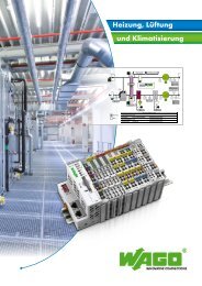
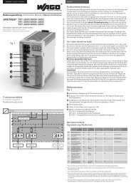
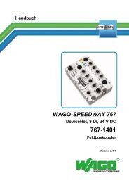
Anzeigen und Parametrisieren über das Display<br />
Setting the parameters using the display<br />
Allgemeine Funktionen<br />
Allgemein: Nur wenn die Tasten-Symbole AB im LC-<br />
Display aufleuchten, ist die jeweilige Taste auch aktiv.<br />
Standardanzeige: Betätigt man für 30 Sekunden<br />
keine Taste, schaltet das Modul automatisch zur<br />
Standard-Anzeige zurück.<br />
Reset: Betätigt man für 5 Sekunden beide Tasten<br />
gleichzeitig, erfolgt ein Reset aller parametrisierbaren<br />
Parameter auf die Werkseinstellung. Dabei werden<br />
alle gespeicherten Min/Max-Werte sowie der<br />
letzte Fehler zurückgesetzt.<br />
Zeitlimit: Wenn zwischen den Eingaben (auch<br />
während des Parametrisierens) länger als 30<br />
Sekunden keine Taste betätigt wird, werden alle<br />
gemachten Eingaben zurückgesetzt und es erfolgt ein<br />
automatischer Wechsel zur Standardanzeige.<br />
Update: Falls Parameter über den PC verändert<br />
werden, entsprechen diese neuen Parameter<br />
automatisch der Reset-Konfiguration. Die<br />
Werkseinstellung wird überschrieben.<br />
1 Standardanzeige<br />
Zeigt die aktuelle Eingangsspannung, die Ausgangsspannung<br />
und den Ausgangsstrom an. Zusätzlich<br />
wird in der 2. Zeile von oben der aktuelle Ladezustand<br />
(im Normalbetrieb) bzw. die Restlaufzeit (im<br />
Pufferbetrieb) angezeigt.<br />
2 Ladespannung und -strom<br />
Zeigt die aktuelle Ladespannung und den Ladestrom<br />
an.<br />
3 Minimal- und Maximalwerte<br />
Die minimal gemessene Eingangsspannung und<br />
der maximal gemessene Ausgangsstrom werden<br />
angezeigt.<br />
4 Temperaturgeführtes Akkumanagement<br />
In Abhängigkeit der Temperatur im Akkumodul<br />
werden die optimalen Ladeparameter automatisch<br />
eingestellt. Es ist ebenfalls möglich, eine konstante<br />
Ladeerhaltungsspannung zu konfigurieren ( Phase 3<br />
gemäß Ladekennlinie)<br />
B = zum Deaktivieren des temperaturabhängigen<br />
Akkumanagements<br />
A = temperaturabhängiges Akkumanagement (de)<br />
aktivieren (ON/OFF)<br />
B = konstante Ladeerhaltungsspannung einstellen<br />
(26 bis 29,5 Vdc)<br />
B = Änderung speichern<br />
5 Pufferzeit<br />
Die Pufferzeit kann eingestellt werden.<br />
B = zum Ändern der Pufferzeit<br />
A = Pufferzeit ändern<br />
(10 Sek. bis 10 Min. / dauerhaft)<br />
B = Pufferzeit speichern<br />
6 Erkennung der Akkumodule<br />
Akkumodule mit „Battery Control“ werden automatisch<br />
erkannt und der Kapazitätswert wird angezeigt.<br />
Wird anstelle des Kapazitätswertes für das<br />
verwendete Akkumodul „---“ angezeigt, so konnte<br />
kein Akkumodul erkannt werden. In diesem Fall wird<br />
der maximale Ladestrom zur Verfügung gestellt<br />
und die Ladung erfolgt mit konstanter Ladeerhaltungsspannung<br />
( Phase 3 gemäß Ladekennlinie)<br />
B = zum Deaktivieren der automatischen Erkennung<br />
von verwendeten Akkumodulen<br />
A = Erkennung (de)aktivieren (ON/OFF)<br />
B = Änderung speichern<br />
7 Betriebsstunden des<br />
Akkumoduls<br />
Die Betriebsstunden des verwendeten Akkumoduls<br />
können abgelesen werden und auf Null zurückgesetzt<br />
werden.<br />
B = zum Zurücksetzen der Betriebsstunden<br />
8 Fehlermanager<br />
Anhand des Fehlercodes (siehe auch Aufkleber am<br />
Gehäuse) kann anhand der blinkenden Segmente<br />
eine Fehleranalyse vorgenommen werden.<br />
Der letzte Fehler wird fest gespeichert, so dass<br />
auch noch nach einem Neustart des Moduls eine<br />
Fehlerursache detektiert werden kann.<br />
B = letzten Fehler anzeigen<br />
A = mit diesem Befehl (linke Taste) kommen Sie zum nächsten Menüpunkt<br />
A = pressing the left button means move to next menu point<br />
General functions<br />
General: The buttons AB are only active when<br />
the appropriate symbol in the display is alight.<br />
Standard display: If no button is operated for 30<br />
seconds the unit will return to the standard display<br />
mode.<br />
Reset: If both buttons are pressed simultaneously<br />
for 5 seconds then all parameters settings will return<br />
to the factory set condition. This means all saved<br />
min/max. values and the last fault condition will<br />
be reset.<br />
Time limit: If between the input programming (also<br />
parameter settings) a time interval of over 30<br />
seconds has lapsed without pressing any button, then<br />
all entries will be reset, and the display will return to<br />
the standard display mode.<br />
Update: If the parameters have been changed using a<br />
PC then these settings will automatically be the reset<br />
parameters. The factory settings will be lost.<br />
1 Standard display<br />
Shows the actual input voltage, output voltage and<br />
output current.<br />
Additional information on 2. row: Charge status<br />
(normal operation) and remaining time of the<br />
batteries (buffer operation).<br />
2 Charging voltage and current<br />
Shows the actual charging voltage and current.<br />
3 Minimum and maximum values<br />
The min. input voltage and the max. output current<br />
are displayed.<br />
4 Temperature tracked battery<br />
management<br />
The device regulates the optimal charge-voltage for<br />
the battery module automatically. It is also possible<br />
to adjust a fixed charge-voltage. (Only phase 3 will<br />
be used for charging)<br />
B = to change the temperature tracked battery<br />
management<br />
A = to (de)activate temperature tracked battery<br />
management (ON/OFF)<br />
B = to adjust a fixed charge-voltage<br />
(26 to 29.5Vdc)<br />
B = save changes<br />
5 Puffer time setting<br />
The time for puffer operation can be adjusted.<br />
B = to adjust time for puffer operation<br />
A = adjust puffer time setting<br />
(10 seconds to 10 minutes / constant)<br />
B = save puffer operation<br />
6 Detection of battery module<br />
Battery modules with „Battery Control“ will detect<br />
automatically. The rated capacity will showed.<br />
When displayed „---“instead of the capacity value,<br />
no battery module was detected.<br />
At this setting the maximal load current will be<br />
supplied. The battery will be charged with a constant<br />
charging voltage (Phase 3 according to the<br />
loading chart)<br />
B = to change the automatic detection<br />
A = to (de)activate the detection (ON/OFF)<br />
B = save changes<br />
7 Operational hours of the battery<br />
module<br />
The operational hours for the accumulators inside<br />
of the battery module can be displayed and reset.<br />
B = to reset the operational hours and set it to „0“<br />
8 Fault manager<br />
A fault analysis can be made according to the<br />
blinking segments of the display (see ratings plate<br />
on housing).<br />
The last fault symptom will be automatically saved,<br />
so that even after a new start of the module a fault<br />
analysis can be made.<br />
B = show last fault condition.<br />
1<br />
Ui [V]<br />
25,4<br />
!!<br />
24,6<br />
8,03Io<br />
Uo [V]<br />
I<br />
[A]<br />
3<br />
Ui [V]<br />
23,1<br />
U.Lo<br />
I.Hi<br />
10,4Io<br />
[A]<br />
4<br />
TEP<br />
0n<br />
TEP<br />
OFF<br />
U.AC<br />
SET<br />
26.6<br />
STO<br />
6<br />
AUT<br />
BAT<br />
On<br />
3.2<br />
AUT<br />
BAT<br />
Off<br />
SET<br />
STO<br />
8<br />
!!!<br />
Err<br />
$!!<br />
Err<br />
2<br />
BAT<br />
Uo [V]<br />
25,7<br />
0,43Io<br />
[A]<br />
5<br />
120<br />
bu.T<br />
999<br />
bu.T<br />
SET<br />
STO<br />
7<br />
OP.T<br />
BAT<br />
001<br />
203<br />
OP.T<br />
BAT<br />
SET<br />
000<br />
STO<br />
1<br />
2<br />
3<br />
4<br />
5<br />
6<br />
7<br />
8<br />
LED: Die grüne LED (a) leuchtet, wenn kein Fehler<br />
vorliegt. Die gelbe LED (b) zeigt Warnungen<br />
an. Die gelbe LED (b) blinkt bei Pufferbetrieb<br />
im 0,4 Sek.-Takt. Die gelbe LED (b) blinkt bei<br />
geringer Akkuspannung im Pufferbetrieb im 0,2<br />
Sek.-Takt. Die rote LED (c) zeigt Fehler an.<br />
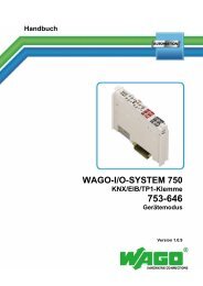
Display der Kontrolleinheit: Das Parametrisieren<br />
über das Display wird rückseitig erklärt.<br />
Tasten: Linke Taste = vorwärts im Menü, rechte<br />
Taste = Parametrisieren.<br />
ACC: Akku-Anschluss<br />
Signale: siehe Anschlussplan rückseitig<br />
Eingang: IN<br />
Ausgang: OUT<br />
Montage: Setzen Sie das Modul mit der Tragschienenführung<br />
an die Oberkante der Tragschiene<br />
an und rasten Sie es nach unten ein.<br />
Demontage: Ziehen Sie den Schnappriegel<br />
mit Hilfe eines Schraubendrehers auf und<br />
hängen Sie das Modul an der Unterkante der<br />
Tragschiene aus.<br />
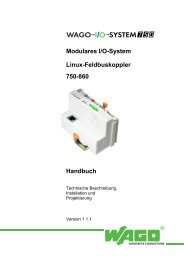
Schnittstelle und Signalausgänge: Die<br />
Schutzkappe ist zur Vermeidung statischer<br />
Entladungen nur unter Anwendung von ESD-<br />
Schutzmaßnahmen abzunehmen. 1 Inaktiv bei<br />
Pufferbetrieb, 2 Inaktiv, wenn kein Akkubetrieb<br />
möglich oder Akkutausch empfohlen,<br />
3 inaktiv bei Abschaltung durch Überstrom,<br />
12 Frei belegbare Ausgänge, konfigurierbar<br />
per PC mit Software, 1 Verknüpfung mit<br />
potenzialfreiem Wechselkontakt, 568 Kommunikationsein-<br />
und Ausgänge,<br />
7 Eingangsspannung des Moduls.<br />
Die Schnittstelle ist nicht galvanisch getrennt.<br />
Ein geeignetes Adapterkabel (787-890) können<br />
Sie optional über WAGO beziehen. Die optionale<br />
Konfigurations- und Visualisierungssoftware<br />
(759-870) können Sie kostenlos unter<br />
www.wago.com/epsitron herunterladen. Bei<br />
Anschluss eines Relais an einen Signalausgang<br />
muss zwingend eine Freilaufdiode vorhanden<br />
sein.<br />
1<br />
2<br />
3<br />
4<br />
5<br />
7<br />
8<br />
9<br />
LED: The green LED (a) lights for normal operation.<br />
The yellow LED (b) shows a warning. The<br />
yellow LED (b) blinks in 0,4 sec. cycle, indicating<br />
puffer operation. The yellow LED (b) blinks when<br />
the battery voltage is low in puffer operation at<br />
0,2 sec. cycle. The red LED (c) indicates a fault<br />
condition.<br />
The control unit display: The parameter<br />
adjustments are described on the back of this<br />
leaflet.<br />
Buttons: Left button = forwards in the menu,<br />
right button = to alter parameter settings.<br />
ACC: accumulator terminals<br />
Signals: see connection plan on the reverse<br />
side<br />
Input: IN<br />
Output: OUT<br />
Mounting: Place the module with the DIN rail<br />
guide on the upper edge of the DIN rail, and snap<br />
it in with a<br />
downward motion.<br />
Removing: Pull the snap lever open with the aid<br />
of a screwdriver and slide the module out at the<br />
lower edge of the DIN rail.<br />
Interface and signal ports: The protective<br />
cap is to reduce the risk of static discharge and<br />
should only be removed with the use of ESD<br />
protective measures 1 Inactive during puffer<br />
operation, 2 inactive, if buffer mode not possible<br />
or accu change recommended, 3 Inactive<br />
if overload protection has operated, 12 free<br />
output connections that can be configured per<br />
PC with software, 1 link to a potential free<br />
switch, 568 communication in and output,<br />
7 output voltage.<br />
The interface has no galvanic separation and<br />
should be only connected with a suitable adapter<br />
cable (787-890) that are optionally available<br />
from WAGO. The optionally software required<br />
for configuration and visualization (759-870)<br />
can be downloaded free of charge from<br />
www.wago.com/epsitron. If a relay is to be connected<br />
to a signal output then it is imperative<br />
that a free running diode be used.<br />
optionales<br />
Zubehör<br />
optional<br />
accessory<br />
Uin<br />
S1 S2 S3<br />
DIN 35 mm<br />
rail<br />
RxPC TxPC<br />
9<br />
Uin<br />
12345678<br />
T<br />
Anschluss<br />
Connection<br />
T<br />
T<br />
Um Verwechslungen mit anderen<br />
Anschlüssen zu vermeiden, verwenden Sie<br />
ausschließlich die mitgelieferten Stecker.<br />
To reduce the risk of mistaking the<br />
terminals, the supplied terminals must<br />
be used.<br />
1<br />
2<br />
3<br />
9<br />
Pin 2 = RxPC<br />
Pin 3 = TxPC<br />
Pin 5 = GND<br />
S1: offen, wenn Modul im Pufferbetrieb<br />
S2: offen, wenn kein Pufferbetrieb möglich oder Akkutausch empfohlen<br />
S3: offen, wenn Ausgang aufgrund von Überstrom abgeschaltet hat<br />
S1: open, if the module is in buffer mode<br />
S2: open, if buffer mode not possible or accu change is recommended<br />
S3: open, if the output has been switched off due to over-current<br />
c<br />
b<br />
a<br />
7<br />
5<br />
OUT<br />
4<br />
ACC<br />
6<br />
IN