Vakuum-Belüftungsventile Nr. 1140 Vacuum relief valves - Krombach
Vakuum-Belüftungsventile Nr. 1140 Vacuum relief valves - Krombach
Vakuum-Belüftungsventile Nr. 1140 Vacuum relief valves - Krombach

Erfolgreiche ePaper selbst erstellen
Machen Sie aus Ihren PDF Publikationen ein blätterbares Flipbook mit unserer einzigartigen Google optimierten e-Paper Software.
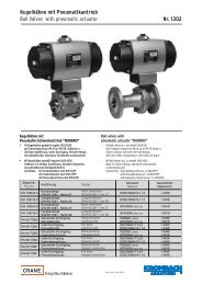
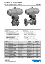
<strong>Vakuum</strong>-Belüftungsventile<br />
<strong>Vacuum</strong> <strong>relief</strong> <strong>valves</strong><br />
<strong>Nr</strong>. <strong>1140</strong><br />
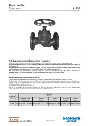
Selbsttätige <strong>Vakuum</strong>-Belüftungsventile<br />
mit Gewindeanschluss ISO 228/1 oder mit Flanschanschluss<br />
Federrohr aus Messing CuZn 39 Pb 3 (W.-<strong>Nr</strong>. 2.0401) mit Einstellskala und Zugfeder<br />
Einstellbereich 1 -0,05 bar entsprechend 0-95 % <strong>Vakuum</strong><br />
Self-operated vacuum <strong>relief</strong> <strong>valves</strong><br />
with threaded connection acc. to ISO 228/1 or with flanged connection<br />
spring tube of brass CuZn39Pb3 (Material No. 2.0401); with adjustable scale and tension spring<br />
Setting range 1-0.05 bar equivalent to 0-95% vacuum<br />
Bestell-<strong>Nr</strong>.<br />
Order No.<br />
VBV 1141<br />
VBV 1142<br />
VBV 1143<br />
VBV 1144<br />
VBV 1145<br />
VBV 1146<br />
VBV 1147<br />
VBV 1148<br />
PN<br />
10<br />
16<br />
10<br />
16<br />
10<br />
16<br />
10<br />
16<br />
DN<br />
G ¾ - G 2<br />
G ¾ - G 2<br />
20-100<br />
20-100<br />
G ¾ - G 2<br />
G ¾ - G 2<br />
20-100<br />
20-100<br />
Ausführung<br />
Design<br />
Gewindeanschluss, Weichdichtung<br />
Threaded connection, soft sealing<br />
Gewindeanschluss, Metalldichtung<br />
Threaded connection, metal sealing<br />
Flanschanschluss, Weichdichtung<br />
Flanged connection, soft sealing<br />
Flanschanschluss, Metalldichtung<br />
Flanged connection, metal sealing<br />
Werkstoffe / Werkstoff-<strong>Nr</strong>.<br />
Gehäuse, Kegel und Spindel<br />
Materials / Material No.<br />
Body, disc and stem<br />
X20Cr13<br />
X20Cr13<br />
X20Cr13<br />
X20Cr13<br />
X6CrNiMoTi17-12-2<br />
X6CrNiMoTi17-12-2<br />
X6CrNiMoTi17-12-2<br />
X6CrNiMoTi17-12-2<br />
1.4021<br />
1.4021<br />
1.4021<br />
1.4021<br />
1.4571<br />
1.4571<br />
1.4571<br />
1.4571
<strong>Vakuum</strong>-Belüftungsventile<br />
<strong>Vacuum</strong> <strong>relief</strong> <strong>valves</strong><br />
<strong>Nr</strong>. <strong>1140</strong><br />
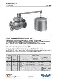
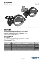
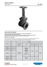
Ventil mit Gewindeanschluss<br />
Valve with threaded end<br />
Ventil mit Flanschanschluss<br />
Valve with flanged end<br />
<strong>Vakuum</strong>-Belüftungsventile<br />
Die Belüftungsventile arbeiten mit Federbelastung und sind als <strong>Vakuum</strong>brecher und Begrenzungsventil verwendbar. Die Ventile sind begrenzt<br />
regelfähig, da sie, bedingt durch die Federspannungszunahme, langsam öffnen. Ein Einsatz als Regelventil ist jedoch nicht möglich, da der Kegel<br />
keine Regelcharakteristik besitzt. Damit die Ventile mit einer genügenden Empfindlichkeit öffnen, ist die Feder für eine <strong>Vakuum</strong>-Zunahme von 0,05<br />
bar ausgelegt, bezogen auf die wirksame Kegelfläche zwischen dem Beginn des Öffnens und der vollen Ventilöffnung. Das bedeutet, dass in dem<br />
ganzen Einstellbereich von 1 bis 0,05 bar die Ventile bei beliebig eingestelltem <strong>Vakuum</strong>, z. B. bei 0,4 bar zu öffnen beginnen und bei 0,35 bar voll<br />
geöffnet sind.<br />
Unter normalen Betriebsbedingungen arbeiten die Ventile wartungsfrei, sofern nicht durch Staubanfall oder durch Fremdkörper an der<br />
Ventilspindel die Leichtgängigkeit beeinträchtigt wird.<br />
Beachtung:<br />
Aus Konstruktionsgründen ist der Flanschanschluss mit einer größeren Nennweite als der Ventil-0 vorgesehen.<br />
<strong>Vacuum</strong> <strong>relief</strong> <strong>valves</strong><br />
<strong>Vacuum</strong> <strong>relief</strong> <strong>valves</strong> are spring loaded and can be used as vacuum breakers and limiting <strong>valves</strong>. The <strong>valves</strong> can be regulated within certain limits since they open<br />
slowly due to the increase in spring tension. The usage as control valve is not possible since the disc has no control characteristic. The spring has been designed<br />
for a vacuum increase of 0.05 bar (based on the effective disc area between the beginning of opening process and the full valve opening) so that the valve may<br />
open with sufficient sensitivity. Consequently, in the full setting range from 1 bar to 0.05 bar the <strong>valves</strong> may begin to open at any preset vacuum, e.g. at 0.4 bar, and<br />
be fully open at 0.35 bar.<br />
The <strong>valves</strong> are maintenance free under normal operation conditions, provided the valve stem is protected against dust and impurities which could impair easy<br />
operation.<br />
Note:<br />
For design reasons, the flange connection has a nominal size that is larger than the valve diameter.
<strong>Vakuum</strong>-Belüftungsventile<br />
<strong>Vacuum</strong> <strong>relief</strong> <strong>valves</strong><br />
<strong>Nr</strong>. <strong>1140</strong><br />
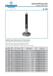
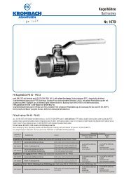
Baumaße und Gewichte<br />
Dimensions and weights<br />
Nennweite<br />
Anschluss ISO 228/1<br />
Ventil-Ø<br />
Einschraubtiefe<br />
Bauhöhe<br />
Bauhöhe<br />
Nominal size<br />
Connection acc. to ISO 228/1<br />
Valve-Ø<br />
Screw-in depth<br />
Height<br />
Height<br />
DN<br />
G<br />
a<br />
n<br />
H<br />
H 1<br />
20<br />
G¾<br />
10<br />
16<br />
235<br />
260<br />
25<br />
G1<br />
15<br />
16<br />
310<br />
335<br />
32<br />
G1¼<br />
20<br />
16<br />
365<br />
390<br />
40<br />
G1½<br />
25<br />
19<br />
365<br />
390<br />
50<br />
G2<br />
32<br />
23<br />
405<br />
435<br />
65<br />
-<br />
40<br />
-<br />
-<br />
615<br />
80<br />
-<br />
50<br />
-<br />
-<br />
685<br />
100<br />
-<br />
65<br />
-<br />
-<br />
775<br />
Gewicht in ca. [kg]<br />
Weight in ca. [kg]<br />
Gewinde<br />
Threaded end<br />
Flansch<br />
Flanged end<br />
1<br />
2<br />
1,5<br />
2,5<br />
2,5<br />
4,5<br />
3<br />
5<br />
3,5<br />
6<br />
-<br />
12<br />
-<br />
13<br />
-<br />
19<br />
Flanschanschlussmaße nach DIN 2501 PN 16 und PN 25<br />
Flange dimensions acc. to DIN 2501, PN 16 and PN 25<br />
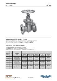
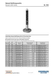
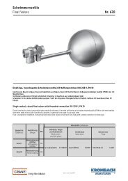
Leistungsdiagramm<br />
Performance diagram<br />
p<br />
i<br />
= Druck im <strong>Vakuum</strong>raum<br />
p a = Atmosphärendruck<br />
1)<br />
100 mbar = 0.01 MPa<br />
p=<br />
i<br />
Pressure in vacuum chamber<br />
p a = Atmospheric pressure<br />
1)<br />
100 mbar = 0.01 MPa<br />
Lieferbare Sonderausführungen:<br />
• Flanschanschluss in anderen Druckstufen oder nach<br />
anderen Normen (ANSI, BS, u.s.w.)<br />
• <strong>Vakuum</strong>-Belüftungsventile komplett in<br />
seewasserbeständiger Bronze, Sphäroguss und<br />
Sonderwerkstoffe wie Monel, Inconel und Hastelloy<br />
• Buntmetallfreie Ausführung<br />
• Dichtscheibe in öl- und benzinbeständigen Qualitäten<br />
• Armatur geeignet für Lebensmitteleinsatz<br />
• <strong>Vakuum</strong>-Belüftungsventil in geschlossener Bauform<br />
mit seitlichem Ansaugstutzen<br />
Special designs:<br />
• Flanged connections for other pressure ratings or made acc. to<br />
other standards (ANSI, BS etc.)<br />
• <strong>Vacuum</strong> <strong>relief</strong> <strong>valves</strong>, completely, in seawater-resistant<br />
bronze,<br />
ductile cast iron or special materials like Monel, Inconel and<br />
Hastelloy,<br />
• Free of nonferrous metals<br />
• Sealing ring of oil and petrol-resistant material grades<br />
• Valve approved for use in the food industry<br />
• <strong>Vacuum</strong> <strong>relief</strong> valve of closed design with lateral suction nozzle
<strong>Vakuum</strong>-Belüftungsventile<br />
<strong>Vacuum</strong> <strong>relief</strong> <strong>valves</strong><br />
<strong>Nr</strong>. <strong>1140</strong><br />
Die beschriebenen Armaturen entsprechen in Ihrer Konstruktion, ihren Abmessungen, Gewichten und Werkstoffen dem derzeitigen Stand der Technik. Änderungen im Zuge der<br />
Weiterentwicklung, sowie die Verwendung gleich- oder höherwertiger Werkstoffe bleiben vorbehalten. Für eventuelle Schreib- oder Übersetzungsfehler übernehmen wir keine Haftung.<br />
The construction, the measurements and the weights of the described <strong>valves</strong> represent the current technical standards. We reserve the right to change the technical details and to use<br />
materials of equivalent and higher quality. We cannot be held responsible for any printing or translation errors that might be found in this catalogue.<br />
02/07<br />
Friedrich <strong>Krombach</strong> GmbH & Co. KG • Armaturenwerke • D-57202 Kreuztal • Postfach 1130<br />
Telefon (0 27 32) 520-00 • Telefax (0 27 32) 520 100 • http//www.krombach.com • e Mail: info@krombach.com