Spindel-Lineareinheiten Linear units with spindle drive
Spindel-Lineareinheiten Linear units with spindle drive
Spindel-Lineareinheiten Linear units with spindle drive

Erfolgreiche ePaper selbst erstellen
Machen Sie aus Ihren PDF Publikationen ein blätterbares Flipbook mit unserer einzigartigen Google optimierten e-Paper Software.
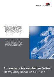
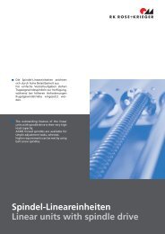
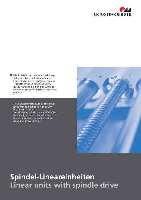
Die <strong>Spindel</strong>-<strong><strong>Linear</strong>einheiten</strong> zeichnen<br />
sich durch hohe Belastbarkeit aus.<br />
Für einfache Verstellaufgaben stehen<br />
Trapezgewindespindeln zur Verfügung,<br />
während bei höheren Anforderungen<br />
Kugelgewindetriebe eingesetzt<br />
werden.<br />
The outstanding feature of the linear<br />
<strong>units</strong> <strong>with</strong> <strong>spindle</strong> <strong>drive</strong> is their very<br />
high load capacity.<br />
ACME thread <strong>spindle</strong>s are available for<br />
simple adjustment tasks, whereas<br />
higher requirements can be met by<br />
using ball screw <strong>spindle</strong>s.<br />
<strong>Spindel</strong>-<strong><strong>Linear</strong>einheiten</strong><br />
<strong>Linear</strong> <strong>units</strong> <strong>with</strong> <strong>spindle</strong> <strong>drive</strong><br />
II - 1
<strong>Spindel</strong>-<strong><strong>Linear</strong>einheiten</strong><br />
<strong>Linear</strong> <strong>units</strong> <strong>with</strong> <strong>spindle</strong> <strong>drive</strong><br />
RK LightUnit<br />
RK LightUnit<br />
Seite 4-23<br />
• “Leichte” <strong>Linear</strong>einheit für<br />
eine Verstellung von Bauteilen<br />
mit geringem Gewicht<br />
• Aluminium-Antriebsspindel<br />
• <strong>Spindel</strong>abdeckung durch<br />
elastische Dichtlippe<br />
• Führungsschlitten u. Befestigungselemente<br />
aus Kunststoff<br />
in vielen Varianten<br />
Page 4-23<br />
• "light" linear unit for the<br />
movement of elements <strong>with</strong><br />
reduced load<br />
• aluminium <strong>drive</strong> <strong>spindle</strong><br />
• elastic plastic non-leaking<br />
lips covering the <strong>spindle</strong><br />
• plastic guide and fixation<br />
elements in several versions.<br />
Rohrsystem <strong>Linear</strong>einheit E, AE<br />
Tubular linear unit E, AE<br />
Seite 24-59<br />
• Einfacher und robuster Aufbau<br />
• Große Variantenvielfalt an<br />
Führungsschlitten und Befestigungselementen<br />
• Kostengünstig<br />
Page 24-59<br />
• simple and stable structure<br />
• wide range of guide and<br />
fixation elements<br />
• cost-efficient<br />
Rohrsystem <strong>Linear</strong>einheit EP<br />
Tubular linear unit EP<br />
Seite 60-89<br />
• Einfacher und robuster Aufbau<br />
• Für mittleren bis schweren<br />
Belastungsfall<br />
• Kostengünstig<br />
Page 60-89<br />
• simple and stable structure<br />
• suited for medium to high<br />
loads<br />
• cost-efficient<br />
Rohrsystem <strong>Linear</strong>einheit EPX<br />
Tubular linear unit EPX<br />
Seite 72-89<br />
• Grundsystem entspricht<br />
EP-Baureihe<br />
• Führungsschlitten aus zwei<br />
Elementen, die durch eine<br />
Aufspannplatte verbunden<br />
sind<br />
• Aufnahme großer Momente<br />
Page 72-89<br />
• same basic structure as the<br />
EP product range<br />
• guide tables consist of two<br />
elements connected by a<br />
connecting plate<br />
• suited for high loads<br />
COPAS <strong>Linear</strong>einheit<br />
COPAS linear unit<br />
Seite 90-117<br />
• Hohe Tragzahlen<br />
• Präziser Lauf durch Kugelbuchsenführung<br />
• Führungswelle aus Vergütungsstahl,<br />
induktiv gehärtet,<br />
geschliffen und poliert<br />
• Ausführungen auch mit Kugelgewindespindel<br />
lieferbar<br />
Page 90-117<br />
• high load capacity<br />
• precise running through ball<br />
bushing <strong>drive</strong><br />
• guide shafts made of<br />
heat-treated steel,<br />
inductively hardened,<br />
ground and polished<br />
• also available <strong>with</strong> ball screw<br />
<strong>spindle</strong><br />
II - 2<br />
RK Rose+Krieger GmbH & Co. KG Postfach 15 64 D-32375 Minden
I<br />
Profil <strong>Linear</strong>einheit PLM-II<br />
Profile linear unit PLM-II<br />
Seite 118-137<br />
• kleine Baureihe zur Justierung<br />
und Posionierung leichter<br />
bis mittelschwerer<br />
Gegenstände<br />
• Drehgriff mit Nonius<br />
• 20er Nutgeometrie<br />
Page 118-137<br />
• range of small-size linear<br />
<strong>units</strong> suited for adjustment<br />
and positioning of light to<br />
medium weight devices<br />
• control knob <strong>with</strong> vernier<br />
• slot geometry 20<br />
II<br />
RK Compact<br />
RK Compact<br />
Seite 138-153<br />
• Einheiten durch Standardzubehör<br />
auf einfache Weise zu<br />
Mehrachssystemen kombinierbar<br />
• Sehr gutes Preis-/Leistungsverhältnis<br />
• Drehgriff mit Nonius<br />
Page 138-153<br />
• these linear <strong>units</strong> can be easily<br />
transformed into multi-axis<br />
systems by means of<br />
standard accessories<br />
• very good cost effectiveness<br />
• control knob <strong>with</strong> vernier<br />
III<br />
IV<br />
quad ® <strong>Linear</strong>einheit EV, AV<br />
quad ® linear unit EV, AV<br />
Seite 154-187<br />
• Führungsprofil aus stranggepressten<br />
Aluminium<br />
• Abgedeckte <strong>Spindel</strong>,<br />
dadurch weitgehend vor<br />
Verschmutzung geschützt<br />
• Große Variantenvielfalt an<br />
Führungsschlitten und Befestigungselementen<br />
Page 154-187<br />
• guide profile made of extruded<br />
aluminium<br />
• a cover band keeps the<br />
<strong>spindle</strong> free from dust<br />
• wide range of connecting<br />
elements and fixation elements<br />
V<br />
Profil <strong>Linear</strong>einheit PLS-II<br />
Profile linear unit PLS-II<br />
Seite 188-209<br />
• Führungsprofil und Schlitten<br />
aus stranggepresstem Aluminium<br />
• Schlittenführung mittels<br />
Laufrollen<br />
• Externe Schmierung<br />
• Ausführungen auch mit Kugelgewindespindel<br />
lieferbar<br />
Page 188-209<br />
• guide profile and guide table<br />
made of extruded aluminium<br />
• guide table running on<br />
rollers<br />
• external lubrication<br />
• versions <strong>with</strong> ball screw<br />
<strong>spindle</strong> also available<br />
VI<br />
VII<br />
RK DuoLine S<br />
RK DuoLine S<br />
Seite 210-228<br />
• Wahlweise Kugelschienenoder<br />
Laufrollenführung<br />
• Gekapseltes Führungskonzept<br />
• Zentrale Wartungsöffnung<br />
• Ausführung mit Trapezspindel<br />
oder Kugelgewindetrieb<br />
Page 210-228<br />
• optional roller guide or ball<br />
rail system<br />
• enclosed guide system<br />
• central maintenance<br />
opening<br />
• ACME thread or ball screw<br />
<strong>spindle</strong> versions<br />
VIII<br />
D-LE 03/2003<br />
II - 3<br />
IX
RK LightUnit<br />
RK LightUnit<br />
Bei der Entwicklung der neuen “leichten” <strong>Linear</strong>einheit<br />
RK LightUnit war man speziell auf den Einsatz von<br />
Materialien zur Gewichtsreduzierung bedacht. Hierbei<br />
überträgt eine gleitgelagerte Aluminiumspindel<br />
die Antriebsbewegung auf einen verdrehgesicherten<br />
Kunststoff-Führungsschlitten.DieserSchlittenistwahlweise,<br />
je nach Einsatzfall, in unterschiedlichen Ausführungen<br />
lieferbar. Die <strong>Spindel</strong> ist durch ein spezielles<br />
Dichtlippensystem vor Verschmutzungen geschützt<br />
und erhöht somit die Lebensdauer und entsprechende<br />
Wartungsintervalle.<br />
Weight reduction based on the use of material was one<br />
of the main aims as the new linear unit “RK LightUnit”<br />
was developed. A sliding bearing aluminium <strong>spindle</strong><br />
transmits the <strong>drive</strong> movement to a torsion-free guide<br />
table. This guide table can be ordered in different versions<br />
according to the application requirements. The<br />
<strong>spindle</strong> is protected against dust by a special non-leaking<br />
lip system. This offers a longer lifetime and increases<br />
the maintenance intervals.<br />
Merkmale:<br />
• Antriebsspindel aus Aluminium<br />
• Verdrehgesicherter Kunststoff-Führungsschlitten<br />
wahlweise in verschiedenen Ausführungen<br />
• <strong>Spindel</strong>abdeckung durch elastische Kunststoff-Dichtlippe<br />
• Kunststoff-Endelemente mit Gleitlagerung<br />
• Führungsrohr wahlweise hell oder schwarz eloxiert<br />
• Kunststoff-Befestigungselemente in unterschiedlichen<br />
Varianten lieferbar<br />
Features:<br />
• Aluminium <strong>drive</strong> <strong>spindle</strong><br />
• Torsion-free plastic guide table, available in different<br />
versions<br />
• Elastic plastic non-leaking lips covering the <strong>spindle</strong><br />
• Plastic end element <strong>with</strong> sliding bearing<br />
• Guiding tube natural or anodized black, optional<br />
• Plastic fixation element available in different versions<br />
II - 4<br />
RK Rose+Krieger GmbH & Co. KG Postfach 15 64 D-32375 Minden
I<br />
Inhaltsverzeichnis<br />
Contents<br />
Technische Beschreibung<br />
Technical description<br />
II<br />
Auslegung<br />
Specifications<br />
Seite 6 - 9<br />
Page 6-9<br />
III<br />
RK LightUnit<br />
RK LightUnit<br />
• Rechts- oder Linksgewinde<br />
• Rechts- und Linksgewinde<br />
• right or lefthand thread<br />
• right and lefthand thread<br />
IV<br />
Seite 10 - 13<br />
Page 10 - 13<br />
V<br />
Führungsschlitten<br />
Befestigungselemente<br />
Seite 14 - 19<br />
Guide table<br />
Fixation element<br />
Page 14 - 19<br />
VI<br />
Zubehör<br />
Accessories<br />
VII<br />
Seite 20<br />
Page 20<br />
VIII<br />
D-LE 03/2003<br />
II - 5<br />
IX
RK LightUnit<br />
RK LightUnit<br />
Technische Beschreibung<br />
Technical description<br />
Eine im Führungsrohr (8)<br />
gelagerte Gewindespindel<br />
(6) mit zugeordneter<br />
Leitmutter (4) überträgt<br />
die rotatorische Bewegung<br />
auf den Führungsschlitten<br />
(5). Dieser wird<br />
durch die spezielle Geo-<br />
metriederLeitmutterver-<br />
drehgesichert.<br />
(vergl. Skizze Seite 7)<br />
A threaded <strong>spindle</strong> (6)<br />
<strong>with</strong> corresponding<br />
guide nut (4), supported<br />
in the guide tube (8)<br />
transmits a rotating<br />
movement into a linear<br />
movement of the guide<br />
element (5). This is<br />
prevented from twisting<br />
by a special guide nut<br />
geometry. (see drawing<br />
on page 7)<br />
Trapezgewindespindel<br />
ACME thread <strong>spindle</strong><br />
<strong>Spindel</strong>: AlCuMgPb, gerollte<br />
Ausführung<br />
Leitmutter: POM<br />
Ausführungen:<br />
• Rechtsgewinde<br />
• Linksgewinde<br />
• Rechts-/Linksgewinde<br />
Bemerkung:<br />
niedriger bis mittlerer<br />
Drehzahlbereich, selbsthemmend,<br />
gleitgelagert<br />
Spindle: AlCuMgPb,<br />
rolled version<br />
Guide nut: POM<br />
Versions:<br />
• righthand thread<br />
• lefthand thread<br />
• right / lefthand thread<br />
Remarks:<br />
lower to medium speed<br />
range,<br />
self-locking,<br />
slide bearing<br />
Führungsrohr<br />
Guide tube<br />
Stranggepresstes Aluminiumprofil<br />
nach DIN<br />
17615<br />
Bemerkung:<br />
wahlweise hell oder<br />
schwarz eloxiert<br />
Extruded aluminium<br />
profile according to<br />
DIN 17615<br />
Remark:<br />
clear or black anodized,<br />
optional<br />
Lagerung<br />
Bearing<br />
<strong>Spindel</strong>lagerung:<br />
Endelement als Gleitlager<br />
ausgeführt<br />
Spindle bearing:<br />
The end element is used<br />
as slide bearing<br />
Befestigung der<br />
<strong>Linear</strong>einheit<br />
Fixation of the linear<br />
unit<br />
Je nach Einbaulage und<br />
Anwendung kann die <strong>Linear</strong>einheit<br />
mittels Befestigungselementen<br />
an<br />
Maschinen oder Gestellen<br />
montiert werden.<br />
Fixation elements enable<br />
to attach the linear unit<br />
ontoamachineoraframe<br />
according to installation<br />
and application.<br />
II - 6<br />
RK Rose+Krieger GmbH & Co. KG Postfach 15 64 D-32375 Minden
I<br />
Der Führungsschlitten ist nicht im Lieferumfang der<br />
<strong>Linear</strong>einheit enthalten und muss separat bestellt<br />
werden. Siehe Seite 14.<br />
The guide table has to be ordered separately on<br />
page 14. It is not included in the delivery set.<br />
II<br />
5<br />
10<br />
III<br />
9<br />
4<br />
IV<br />
V<br />
8<br />
VI<br />
7<br />
6<br />
3<br />
VII<br />
2<br />
1<br />
1 - Nutmutter 6 - Gewindespindel<br />
2 - Endelement 7 - Kunststoff-Dichtlippe<br />
3 - Passfeder 8 - Führungsrohr<br />
4 - Leitmutter 9 - Endelement<br />
5 - Führungsschlitten 10 - Nutmutter<br />
1 - Slotted round nut 6 - Threaded <strong>spindle</strong><br />
2 - End element 7 - Plastic non-leaking lips<br />
3 - Feather key 8 - Guide tube<br />
4 - Guide nut 9 - End element<br />
5 - Guide table 10 - Slotted round nut<br />
VIII<br />
D-LE 03/2003<br />
II - 7<br />
IX
RK LightUnit<br />
RK LightUnit<br />
Positioniergenauigkeit<br />
Positioning accuracy<br />
Antriebsart<br />
type of <strong>drive</strong><br />
Trapezgewindespindel<br />
ACME thread <strong>spindle</strong><br />
Positioniergenauigkeit<br />
positioning accuracy<br />
Selbsthemmung<br />
self-locking<br />
±0,3 mm/300 mm Hub travel ja yes<br />
II - 8<br />
RK Rose+Krieger GmbH & Co. KG Postfach 15 64 D-32375 Minden
I<br />
Belastungsdaten*<br />
Loads*<br />
F Kraft [N]<br />
M Moment [Nm]<br />
I Flächenträgheitsmoment [cm 4 ]<br />
F force [N]<br />
M moment [Nm]<br />
I geom. moment of inertia [cm 4 ]<br />
Gesamtlänge total length<br />
II<br />
III<br />
Gesamtlänge [mm]<br />
total length<br />
Durchbiegung [mm]<br />
Deflection<br />
F x F y F z M x M y M z I y I z<br />
300 500 800 1000 300 500 800 1000<br />
1,0 2,5 4,0 5,0 1,0 2,5 4,0 5,0<br />
IV<br />
Kraft force 300 700 550 270 140 1390 1210 600 450 2,5 5,5 5,5 1,90 1,88<br />
*bezogen auf Führungsschlitten (statisch, Endelemente aufliegend)<br />
*referring to the guide table (static, end elements supported)<br />
V<br />
VI<br />
Leerlaufmoment<br />
No-load torque<br />
VII<br />
Type<br />
RK LightUnit 30<br />
Leerlaufmoment<br />
no-load torque<br />
35 Ncm<br />
VIII<br />
D-LE 04/2005<br />
II - 9<br />
IX
RK LightUnit<br />
RK LightUnit<br />
Ausführung<br />
Version<br />
• Rechts- oder Linksgewinde<br />
• Right or lefthand thread<br />
Funktionsprinzip:<br />
Eine Rotationsbewegung der<br />
Gewindespindel wird in eine lineare<br />
Ausgangsbewegung des Führungsschlittens<br />
umgewandelt.<br />
Function:<br />
The rotating movement of the<br />
threaded <strong>spindle</strong> is converted into a<br />
linear movement of the guide table.<br />
Die RK Light Unit ist auch als<br />
Standardlänge lieferbar !<br />
Nutzen Sie den Vorteil einer kurzen Lieferzeit<br />
(ab Lager) und einen günstigeren Bezugspreis.<br />
The RK Light Unit is also available in standard<br />
length !<br />
Take advantage of the short delivery period<br />
(ex warehouse) and the favourable purchase<br />
price!<br />
Standardlängen*<br />
Standard lengths*<br />
Führungsschlitten wahlweise –<br />
dieser muss separat bestellt werden.<br />
Siehe Seite 14-.<br />
[mm]<br />
Code No.<br />
Type<br />
<strong>Spindel</strong><br />
<strong>spindle</strong><br />
Hub<br />
travel<br />
Gesamtlänge<br />
total length<br />
Masse [kg]<br />
weight [kg]<br />
TFA 3000 T_ 0300 30 Tr.14x3 220 300 0,31<br />
TFA 3000 T_ 0500 30 Tr.14x3 420 500 0,51<br />
TFA 3000 T_ 0800 30 Tr.14x3 720 800 0,81<br />
TFA 3000 T_ 1000 30 Tr.14x3 920 1000 1,01<br />
Führungsrohr guide tube:<br />
A = hell eloxiert clear anodized<br />
C = schwarz eloxiert black anodized<br />
*Gesamtlänge 300, 500, 800 und 1000 mm<br />
Führungsrohr hell oder schwarz eloxiert<br />
Rechtsgewinde, 1 Zapfen<br />
*total length 300, 500, 800 and 1000 mm<br />
guide tube clear or black anodized<br />
right hand thread, 1 pin<br />
II - 10<br />
RK Rose+Krieger GmbH Postfach 15 64 D-32375 Minden
I<br />
II<br />
III<br />
IV<br />
Gesamtlänge= Grundlänge + Hub<br />
Total length = basic length + travel<br />
V<br />
Variable Längen<br />
Variable lengths<br />
[mm]<br />
Code No.<br />
RK LightUnit<br />
Type<br />
<strong>Spindel</strong><br />
<strong>spindle</strong><br />
Grundlänge**<br />
basic length**<br />
max. Hub<br />
max. travel<br />
Grundlänge<br />
basic length<br />
Masse [kg]<br />
weight [kg]<br />
pro 100 mm Hub<br />
per 100 mm trav.<br />
TF_ 3000 _ _ _ _ _ _ 30 Tr 14x3 80 920 0,097 0,099<br />
VI<br />
Gesamtlänge Total length<br />
Führungsrohr guide tube:<br />
A = hell eloxiert clear anodized<br />
C = schwarz eloxiert black anodized<br />
T = 1 Zapfen <strong>drive</strong> pin<br />
U = 2 Zapfen <strong>drive</strong> pins<br />
A = Rechtsgewinde righthand thread<br />
H = Linksgewinde lefthand thread<br />
**Die Grundlänge entspricht<br />
der Einheitenlänge ohne Hub.<br />
**The basic length is the length<br />
of the unit <strong>with</strong>out travel.<br />
VII<br />
Bestellbeispiel<br />
RK LightUnit 30<br />
Rechtsgewinde, 2 Zapfen<br />
Führungsrohr hell eloxiert<br />
Hub 500 mm<br />
Order example:<br />
RK LightUnit 30<br />
righthand thread, 2 <strong>drive</strong> pins<br />
guide tube, clear anodized<br />
travel 500 mm<br />
VIII<br />
Code No. + Länge (Grundlänge+Hub)<br />
TFA 3000 UA 0580<br />
Code No. + length (basic length+travel)<br />
TFA 3000 UA 0580<br />
TFA3000UA 0580<br />
D-LE 04/2005<br />
TFA3000UA 0580<br />
II - 11<br />
IX
RK LightUnit<br />
RK LightUnit<br />
Ausführung<br />
Version<br />
• Rechts- und Linksgewinde<br />
• Right and lefthand thread<br />
Funktionsprinzip:<br />
Wie auf Seite 10, jedoch werden 2<br />
Führungsschlitten zusammen bzw.<br />
auseinander gefahren.<br />
Wichtig: Bei der Bestellung wird der<br />
Gesamthub angegeben.<br />
Function:<br />
As described on page 10, but in this<br />
case two guide tables will be moved<br />
together or apart.<br />
Attention: Please indicate the total<br />
travel when ordering.<br />
Führungsschlitten wahlweise –<br />
dieser muss separat bestellt werden.<br />
Siehe Seite 14-.<br />
The optional guide table is to be<br />
ordered separately on page 14-. It is<br />
not included in the delivery set.<br />
Rechtsgewinde<br />
righthand thread<br />
Linksgewinde<br />
(Zapfenseite)<br />
lefthand thread<br />
(pin side)<br />
Code No.<br />
RK LightUnit<br />
Type<br />
<strong>Spindel</strong><br />
<strong>spindle</strong><br />
Grundlänge*<br />
basic length<br />
max. Hub<br />
max. travel<br />
Grundlänge<br />
basic length<br />
Masse [kg]<br />
weight [kg]<br />
pro 100 mm Hub<br />
per 100 mm travel<br />
TFC 3000 _ _ _ _ _ _ 30 Tr 14x3 130 870 0,113 0,099<br />
Gesamtlänge Total length<br />
Führungsrohr guide tube:<br />
A = hell eloxiert clear anodized<br />
C = schwarz eloxiert black anodized<br />
[mm]<br />
S = 1 Zapfen an Linksgewindeseite<br />
1 <strong>drive</strong> pin on the lefthand thread side<br />
T = 1 Zapfen an Rechtsgewindeseite<br />
1 <strong>drive</strong> pin on the righthand thread side<br />
U = 2 Zapfen<br />
2 <strong>drive</strong> pins<br />
* Die Grundlänge entspricht<br />
der Einheitenlänge ohne Hub.<br />
* The basic length is the length<br />
of the unit <strong>with</strong>out travel.<br />
II - 12<br />
RK Rose+Krieger GmbH Postfach 15 64 D-32375 Minden
I<br />
II<br />
III<br />
IV<br />
Gesamtlänge= Grundlänge + Hub<br />
Total length = basic length + travel<br />
V<br />
VI<br />
VII<br />
Bestellbeispiel<br />
RK LightUnit 30<br />
Rechts-/Linksgewinde,<br />
1 Zapfen auf Linksgewindeseite<br />
Führungsrohr schwarz eloxiert<br />
Hub 500 mm<br />
Code No. + Länge (Grundlänge+Hub)<br />
TFC 3000 SC 0630<br />
Order example:<br />
RK LightUnit 30<br />
Right / lefthand thread,<br />
1 <strong>drive</strong> pin on the lefthand thread side<br />
guide table, black anodized<br />
Travel 500 mm<br />
Code No. + length (basic length+travel)<br />
TFC 3000 SC 0630<br />
VIII<br />
TFC3000SC 0630<br />
D-LE 04/2005<br />
TFC3000SC 0630<br />
II - 13<br />
IX
Führungsschlitten RK LightUnit<br />
Guide tables RK LightUnit<br />
Ergänzend zur Bestellnummer der gewählten <strong>Linear</strong>einheit<br />
RK LightUnit wird die Angabe des Führungsschlittens<br />
benötigt.<br />
Entsprechend dem Einsatz der RK LightUnit kann zwischen<br />
unterschiedlichen Ausführungen gewählt werden.<br />
Standardmäßig ist der Führungsschlitten mit<br />
Schrauben bestückt. Diese können bei Bedarf durch<br />
Klemmhebel (siehe Zubehörprogramm auf Seite 20)<br />
ausgetauscht werden.<br />
Material: verstärktes Polyamid, schwarz<br />
Befestigungsmaterial: verzinkt oder Edelstahl<br />
It is necessary to indicate the guide table in addition to<br />
the selected linear unit RK LightUnit.<br />
According to application, the RK LightUnit can be ordered<br />
in different versions. The guide table is fitted <strong>with</strong><br />
stainless steel screws as standard. They can be exchanged<br />
<strong>with</strong> clamping levers if necessary (see accessories<br />
programme on page 20).<br />
Material: reinforced polyamide, black<br />
Fixation element: zinc-plated or stainless steel<br />
Bestellbeispiel<br />
Order example<br />
• Führungsschlitten für RK Lightunit 30<br />
• Befestigung Rohr Ø 25 quer zur<br />
<strong>Linear</strong>einheit<br />
K-KU 30<br />
Code No.<br />
13 00 12 00 C R25<br />
• Guide table for RK Lightunit 30<br />
• Fixation tube Ø 25 transverse to the linear<br />
unit<br />
K-KU 30<br />
Code No.<br />
13 00 12 00 C R25<br />
K-KU<br />
Code No.<br />
Type<br />
Klemmung A<br />
clamping A<br />
13 00 12 00 C _ _ _ _ K-KU 30<br />
Ø20, 25, 30<br />
20<br />
Klemmung A<br />
clamping A<br />
R20 = Ø20<br />
V20 = 20<br />
R25 = Ø25<br />
Schrauben:<br />
S = Stahl, verzinkt (Standard)<br />
E = Edelstahl<br />
screws:<br />
S = zinc-plated (standard)<br />
E = stainless steel<br />
FK-KU<br />
Code No.<br />
Type<br />
13 00 92 00 C _ FK-KU 30<br />
Schrauben:<br />
S = Stahl, verzinkt (Standard)<br />
E = Edelstahl<br />
screws:<br />
S = zinc-plated (standard)<br />
E = stainless steel<br />
II - 14<br />
RK Rose+Krieger GmbH Postfach 15 64 D-32375 Minden
I<br />
W-KU<br />
Code No.<br />
Type<br />
13 00 72 00 C _ _ _ _ W-KU 30<br />
Klemmung A<br />
clamping A<br />
R20 = Ø20<br />
V20 = 20<br />
R25 = Ø25<br />
Klemmung A<br />
clamping A<br />
Ø20, 25, 30<br />
20<br />
II<br />
III<br />
Schrauben:<br />
S = Stahl, verzinkt (Standard)<br />
E = Edelstahl<br />
screws:<br />
S = zinc-plated (standard)<br />
E = stainless steel<br />
IV<br />
FS-KU<br />
Code No.<br />
Type<br />
13 01 12 00 C _ FS-KU 30<br />
Schrauben:<br />
S = Stahl, verzinkt (Standard)<br />
E = Edelstahl<br />
screws:<br />
S = zinc-plated (standard)<br />
E = stainless steel<br />
V<br />
VI<br />
LW-KU<br />
Code No.<br />
Type<br />
13 01 42 00 C _ LW-KU 30<br />
VII<br />
Schrauben:<br />
S = Stahl, verzinkt (Standard)<br />
E = Edelstahl<br />
screws:<br />
S = zinc-plated (standard)<br />
E = stainless steel<br />
VIII<br />
D-LE 04/2005<br />
II - 15<br />
IX
Führungsschlitten RK LightUnit<br />
Guide table RK LightUnit<br />
GW-KU<br />
Code No.<br />
Type<br />
13 01 62 00 C _ _ _ _ GW-KU 30<br />
Klemmung A<br />
clamping A<br />
Ø20, 25, 30<br />
20<br />
Klemmung A<br />
clamping A<br />
R20 = Ø20<br />
V20 = 20<br />
R25 = Ø25<br />
Schrauben:<br />
S = Stahl, verzinkt (Standard)<br />
E = Edelstahl<br />
screws:<br />
S = zinc-plated (standard)<br />
E = stainless steel<br />
II - 16<br />
RK Rose+Krieger GmbH Postfach 15 64 D-32375 Minden
I<br />
II<br />
III<br />
IV<br />
V<br />
VI<br />
VII<br />
VIII<br />
D-LE 04/2005<br />
II - 17<br />
IX
Befestigungselement RK LightUnit<br />
Fixation element RK LightUnit<br />
Mit den Befestigungselementen können die <strong><strong>Linear</strong>einheiten</strong><br />
problemlos in bestehende Konstruktionen eingebunden<br />
werden. Je nach Einsatzfall stehen unterschiedliche<br />
Ausführungen zur Auswahl.<br />
Ein spezielles Reduzierhülsensystem ermöglicht die<br />
Anbindung an verschiedene Rohrdurchmesser.<br />
Material: erstärkter Polyamid, schwarz<br />
Befestigungsmaterial: verzinkt oder Edelstahl<br />
Due to the fixation element, it is possible to attach the<br />
linear <strong>units</strong> to an existing installation. According to<br />
application, different versions are available.<br />
A special reducing bush system permits a fixation to<br />
different tube diameters.<br />
Material: reinforced polyamide, black<br />
Fixation material: zinc-plated or stainless steel<br />
Bestellbeispiel<br />
Order example<br />
• Befestigungselement für RK Lightunit 30<br />
• Befestigung RohrØ 25 rechtwinklig zur <strong>Linear</strong>einheit<br />
W-KU 30<br />
Code No.<br />
RK100 30 AC<br />
R30 R25<br />
• Fixation element for RK Lightunit 30<br />
• Fixation tube Ø 25 perpendicular to the linear<br />
unit<br />
W-KU 30<br />
Code No.<br />
RK100 30 AC<br />
R30 R25<br />
K-KU<br />
Code No. Type<br />
K0 00 30 AC _ R30 _ _ _ K-KU 30<br />
K0 00 30 BC _ R30 _ _ _ K-KU 30<br />
Verpackungseinh.<br />
Packaging<br />
1 Stk. pcs.<br />
5 Stk. pcs.<br />
Klemmung A<br />
clamping A<br />
Ø20, 25, 30<br />
20<br />
Ø20, 25, 30<br />
20<br />
Klemmung A<br />
clamping A<br />
Schrauben:<br />
S = Stahl, verzinkt (Standard)<br />
E = Edelstahl<br />
screws:<br />
S = zinc-plated (standard)<br />
E = stainless steel<br />
R20 = Ø20 mm<br />
R25 = Ø25 mm<br />
R30 = Ø30 mm<br />
V20 = 20 mm<br />
FK-KU<br />
Code No.<br />
Type<br />
Verpackungseinheit<br />
packaging<br />
K2 00 30 AC _ R30 FK-KU 30 1 Stk. pcs.<br />
K2 00 30 BC _ R30 FK-KU 30 5 Stk. pcs.<br />
Schrauben:<br />
S = Stahl, verzinkt (Standard)<br />
E = Edelstahl<br />
screws:<br />
S = zinc-plated (standard)<br />
E = stainless steel<br />
II - 18<br />
RK Rose+Krieger GmbH Postfach 15 64 D-32375 Minden
I<br />
W-KU<br />
Code No.<br />
Type<br />
Verpackungseinh.<br />
packaging<br />
Klemmung A<br />
clamping A<br />
II<br />
K1 00 30 AC _ R30 _ _ _ W-KU 30<br />
1 Stk. pcs.<br />
Ø20, 25, 30<br />
20<br />
K1 00 30 BC _ R30 _ _ _ W-KU 30<br />
5 Stk. pcs.<br />
Ø20, 25, 30<br />
20<br />
Klemmung A<br />
clamping A<br />
R20 = Ø20 mm<br />
R25 = Ø25 mm<br />
R30 = Ø30 mm<br />
V20 = 20 mm<br />
III<br />
FS-KU<br />
Code No.<br />
Schrauben:<br />
S = Stahl, verzinkt (Standard)<br />
E = Edelstahl<br />
screws:<br />
S = zinc-plated (standard)<br />
E = stainless steel<br />
Type<br />
Verpackungseinheit<br />
packaging<br />
K3 00 30 AC _ R30 FS-KU 30 1 Stk. pcs.<br />
K3 00 30 BC _ R30 FS-KU 30 5 Stk. pcs.<br />
IV<br />
V<br />
Schrauben:<br />
S = Stahl, verzinkt (Standard)<br />
E = Edelstahl<br />
screws:<br />
S = zinc-plated (standard)<br />
E = stainless steel<br />
VI<br />
GF-KU<br />
Code No.<br />
Type<br />
Verpackungseinheit<br />
packaging<br />
K8 02 30 AC _ R30 GF-KU 30 1 Stk. pcs.<br />
K8 02 30 BC _ R30 GF-KU 30 5 Stk. pcs.<br />
Schrauben:<br />
S = Stahl, verzinkt (standard)<br />
E = Edelstahl<br />
screws:<br />
S = zinc-plated (standard)<br />
E = stainless steel<br />
VII<br />
VIII<br />
D-LE 04/2005<br />
II - 19<br />
IX
Zubehör RK LightUnit<br />
Accessories RK LightUnit<br />
Klemmhebel<br />
Clamping lever<br />
• Zur Bestückung von Befestigungselementen<br />
und Führungsschlitten<br />
Material: Griff aus PA, schwarz<br />
Schraubeneinsatz aus VA<br />
• Fixation elements and guide<br />
table can be fitted <strong>with</strong> a<br />
clamping lever.<br />
Material: Handle made of<br />
polyamide,black<br />
Screw made of stainless steel<br />
Code No. Type A B C D E G H K L M<br />
9.02321 30 65 48,5 36,5 M8 14 20° 20 13 52,5 18<br />
[mm]<br />
Handrad<br />
Handwheel<br />
• Modernes Design<br />
• Sehr guter Rundlauf<br />
• Drehbarer Zylindergriff<br />
Material: verstärkter<br />
Thermoplast, schwarz<br />
Nabenbuchse Stahl, brüniert<br />
• Modern design<br />
• Very good rotation<br />
• Revolving handle<br />
Material: hardened thermoplastic,<br />
black<br />
Hub bush: burnished steel<br />
Code No.<br />
Type<br />
9.0973 Handrad handwheel Ø80<br />
II - 20<br />
RK Rose+Krieger GmbH Postfach 15 64 D-32375 Minden
I<br />
Reduzierhülsen<br />
Reducing bushes<br />
• Eine Veränderung des Rohrdurchmessers<br />
ist durch einfaches<br />
Wechseln der Reduzierhülsen<br />
möglich<br />
• Bei den Befestigungselementen<br />
können die Hülsen bereits<br />
mit der Bestellnummer<br />
ausgewählt werden und sind<br />
im Lieferumfang enthalten<br />
• It is possible to modify the<br />
tube diameter by a simple<br />
exchange of the reducing<br />
bush<br />
• The reducing bushes can be<br />
selected when ordering the<br />
fixation element. It is<br />
therefore not necessary to<br />
order them seperatly<br />
II<br />
Material: PA6.6 GF30<br />
Material: PA6.6 GF30<br />
III<br />
Axial- u. Verdrehsicherung<br />
Prevention from axial deviation and twisting<br />
IV<br />
Angabe des Rohrdurchmessers<br />
Tube diameter indication<br />
V<br />
Ausführung “R”<br />
Version “R”<br />
Ausführung “V”<br />
Version “V”<br />
VI<br />
[mm]<br />
VII<br />
Code No.<br />
Type<br />
Ausführung<br />
version<br />
Verpackungseinheit<br />
packaging<br />
A+0,1 B C D E L<br />
9.6204 AC 30 R20 1 Stk. pcs. 20,25 30 3,5 18,9 3,4 45<br />
9.6204 BC 30 R20 5 Stk. pcs. 20,25 30 3,5 18,9 3,4 45<br />
9.6206 AC 30 R25 1 Stk. pcs. 25,25 30 3,5 18,9 3,4 45<br />
9.6206 BC 30 R25 5 Stk. pcs. 25,25 30 3,5 18,9 3,4 45<br />
9.6208 AC 30 V20 1 Stk. pcs. 20,25 30 3,5 18,9 3,4 45<br />
9.6208 BC 30 V20 5 Stk. pcs. 20,25 30 3,5 18,9 3,4 45<br />
VIII<br />
D-LE 03/2003<br />
II - 21<br />
IX
Zubehör RK LightUnit<br />
Accessories RK LightUnit<br />
II - 22<br />
RK Rose+Krieger GmbH & Co. KG Postfach 15 64 D-32375 Minden
I<br />
II<br />
III<br />
IV<br />
V<br />
VI<br />
VII<br />
VIII<br />
D-LE 03/2003<br />
II - 23<br />
IX
Rohrsystem <strong>Linear</strong>einheit E / AE<br />
Tubular linear unit E / AE<br />
Aus der Serienkomponente Rohr-Verbindungssystem<br />
entstand das Rohrsystem <strong><strong>Linear</strong>einheiten</strong>-Programm.<br />
Die Rohrsystem <strong><strong>Linear</strong>einheiten</strong> sind rationell, kostengünstig<br />
und universell einsetzbar.<br />
Gute Steifigkeit, geringe Durchbiegung, hohe Belastung,<br />
einfache Handhabung sind ideal in den <strong><strong>Linear</strong>einheiten</strong><br />
vereinigt.<br />
Für die unterschiedlichen Einsatzfälle und Belastungen<br />
stehen je vier bzw. fünf Baugrößen zur Auswahl. Führungsrohrdurchmesser<br />
18-80 mm. Lieferbar sind mehr<br />
als 50 Grundtypen in 160 Varianten.<br />
The product range tubular linear <strong>units</strong> has been developed<br />
from the standard components of the tubular<br />
connection system.<br />
The tubular linear <strong>units</strong> are economical, cost-effective<br />
and universally usable.<br />
High rigidity, low deflection, high loads, easy handling<br />
are ideally combined in this linear unit.<br />
Four and in some instances five different sizes of linear<br />
<strong>units</strong> are available for different applications and loads.<br />
Guide tubes ranging from 18-80 mm. More than 50<br />
basic versions in 160 variations can be delivered.<br />
Merkmale<br />
• Serienmäßige Verfahrwege bis über 2.000 mm<br />
möglich<br />
• Positioniergenauigkeit bis zu ±0,2 mm auf 300 mm<br />
erreichbar<br />
• Verfahrgeschwindigkeit bis 1,5 m/min<br />
• Antrieb über Trapezgewindespindel<br />
• Einbaulage beliebig<br />
Features<br />
• travel of more than 2000 mm possible<br />
• positioning accuracy up to ±0,2 mm / 300 mm<br />
• travelling speed up to 1,5 m/min<br />
• <strong>drive</strong>n by ACME thread <strong>spindle</strong><br />
• installation as desired<br />
II - 24<br />
RK Rose+Krieger GmbH & Co. KG Postfach 15 64 D-32375 Minden
I<br />
Inhaltsverzeichnis<br />
Contents<br />
Technische Beschreibung<br />
Technical description<br />
II<br />
Auslegung<br />
Specifications<br />
Seite 26 - 29<br />
Page 26 - 29<br />
III<br />
Baureihe E<br />
Type E<br />
• Rechts- oder Linksgewinde<br />
• right or lefthand thread<br />
• Rechts- und Linksgewinde<br />
• right and lefthand thread<br />
• Geteilte Gewindespindel<br />
Seite 30 - 35<br />
• split <strong>spindle</strong><br />
Page 30 - 35<br />
IV<br />
Baureihe AE<br />
Type AE<br />
V<br />
Seite 36<br />
Page 36<br />
Führungsschlitten<br />
Guide elements<br />
VI<br />
Befestigungselemente<br />
Fixation elements<br />
Seite 38 - 51<br />
Page 38 - 51<br />
VII<br />
Zubehör<br />
Accessories<br />
Seite 52 - 59<br />
Page 52 - 59<br />
VIII<br />
D-LE 02/2004<br />
II - 25<br />
IX
Rohrsystem <strong>Linear</strong>einheit E / AE<br />
Tubular linear unit E / AE<br />
Technsiche Beschreibung<br />
Technical description<br />
Eine im Führungsrohr (9)<br />
gelagerte Gewindespindel<br />
(6) mit zugeordneter<br />
Leitmutter (8) überträgt<br />
die rotatorische Bewegung<br />
auf den Führungs-<br />
schlitten (10). Dieser<br />
wird durch den Mitnehmerkeil<br />
(7) verdrehgesichert.<br />
(vergl. Skizze Seite 27)<br />
A threaded <strong>spindle</strong> (6)<br />
<strong>with</strong> corresponding<br />
guide nut (8) which is<br />
supported in the guide<br />
tube (9) converts a<br />
rotating(7) movement<br />
into a linear movement<br />
of the guide element<br />
(10). This is protected<br />
against twisting by a <strong>drive</strong><br />
key (7). (see drawing<br />
on page 27)<br />
Trapezgewindespindel<br />
ACME <strong>spindle</strong><br />
<strong>Spindel</strong>: Stahl, optional<br />
Edelstahl,18-60 gestrehlte,<br />
80 gewirbelte Ausführung<br />
Leitmutter: RG 7<br />
Ausführungen:<br />
• Rechtsgewinde<br />
• Linksgewinde<br />
• Rechts-/Linksgewinde<br />
• Geteilte <strong>Spindel</strong><br />
Bemerkung:<br />
mittlerer Drehzahlbereich,<br />
selbsthemmend,<br />
wahlweise wälz- oder<br />
gleitgelagert<br />
<strong>spindle</strong>: steel, stainless<br />
steel optional, 18-60<br />
chased, 80 whirled version<br />
guide nut: RG7<br />
versions:<br />
• righthand<br />
• lefthand<br />
remarks:<br />
medium speed range,<br />
self-locking,<br />
antifriction or slide<br />
bearing, as an option<br />
Führungsrohr<br />
Guide tube<br />
Präzisionsstahlrohr nach<br />
DIN EN 10305<br />
Edelstahlrohr nach<br />
DIN 17458<br />
Führungsschlitz:<br />
Winkelabweichung<br />
0,1mm / 300 mm<br />
Bemerkung:<br />
Rohre werden zusätzlich<br />
geschliffen.<br />
Rauhtiefe R a = 1,6 µm<br />
precision steel tube<br />
complying <strong>with</strong><br />
DIN EN 10305<br />
stainless steel tube complying<br />
<strong>with</strong> DIN 17458<br />
guiding slot:<br />
angular deviation 0,1mm<br />
per 300mm<br />
remarks:<br />
tubes are additionally<br />
polished.<br />
Peak-to-valley height<br />
R a = 1,6 µm<br />
Lagerung<br />
Bearing<br />
<strong>Spindel</strong>lagerung:<br />
Type 18 Flanschlager<br />
30-80 Rillenkugellager<br />
(abgedichtet)<br />
wahlweise<br />
Gleitlager<br />
Schlittenlagerung:<br />
Wahlweise mit oder<br />
ohne Gleitbuchse<br />
<strong>spindle</strong> bearing:<br />
Type 18 flange bearing<br />
30-80 deep<br />
groove ball<br />
bearing (sealed)<br />
or slide bearing<br />
as an option<br />
guide elements bearing:<br />
as an option: <strong>with</strong> or<br />
<strong>with</strong>out slide bushing<br />
Befestigung der <strong>Linear</strong>einheit<br />
Je nach Einbaulage und<br />
Anwendung kann die <strong>Linear</strong>einheit<br />
mittels Befestigungselementen<br />
fixiert werden. Hierzu<br />
stehen neben den Befestigungselementen<br />
auf<br />
den Seiten 46 bis 51 die<br />
Klemmstücke aus dem<br />
Katalog “Verbindungssysteme<br />
zur Verfügung.<br />
Fixation of the linear unit<br />
According to the<br />
installation and<br />
application, the linear<br />
unit can be<br />
fixed <strong>with</strong> clamping<br />
elements.<br />
The fixation elements<br />
mentioned in this<br />
catalogue on pages II 46<br />
to 51as well as the<br />
clamping elements<br />
from the catalogue<br />
"Connection Systems"<br />
can be used for this<br />
purpose.<br />
II - 26<br />
RK Rose+Krieger GmbH Postfach 15 64 D-32375 Minden
I<br />
Der Führungsschlitten<br />
ist nicht im Lieferumfang<br />
der <strong>Linear</strong>einheit<br />
enthalten und muss separat<br />
bestellt werden.<br />
Siehe Seite 38-45<br />
The guide element is<br />
not included in the delivery<br />
set. It has to be<br />
ordered separately.<br />
See page 38-45<br />
13<br />
14<br />
II<br />
III<br />
12<br />
11<br />
9<br />
10<br />
IV<br />
Zusätzliches Passelement<br />
nur bei E 80<br />
Additional fitting<br />
element only <strong>with</strong> E 80<br />
7<br />
8<br />
V<br />
6<br />
5<br />
Abbildung zeigt E 40<br />
Illustration shows E 40<br />
VI<br />
4<br />
2<br />
3<br />
VII<br />
1<br />
1 - Nutmutter 8 - Leitmutter<br />
2 - Gleitlager (wahlweise) 9 - Führungsrohr<br />
3 - Rillenkugellager 10 - Führungsschlitten<br />
4 - Lagerhülse 11 - Lagerhülse<br />
5 - Passfeder 12 - Rillenkugellager<br />
6 - Gewindespindel 13 - Gleitlager (wahlweise)<br />
7 - Mitnehmerkeil 14 - Nutmutter<br />
D-LE 02/2004<br />
1 - slotted round nut 8 - guide nut<br />
2 - slide bearing (as an option) 9 - guide tube<br />
3 - deep groove ball bearing 10 - guide element<br />
4 - bearing sleeve 11 - bearing sleeve<br />
5 - feather key 12 - deep groove ball bearing<br />
6 - <strong>spindle</strong> 13 - slide bearing (as an option)<br />
7 - <strong>drive</strong> key 14 - slotted round nut<br />
II - 27<br />
VIII<br />
IX
Rohrsystem <strong>Linear</strong>einheit E / AE<br />
Tubular linear unit E / AE<br />
Positioniergenauigkeit<br />
Positioning accuracy<br />
Antriebsart<br />
type of <strong>drive</strong><br />
Positioniergenauigkeit<br />
positioning accuracy<br />
Selbsthemmung<br />
self -locking<br />
Trapezgewindespindel<br />
ACME thread <strong>spindle</strong><br />
± 0,2 mm / 300 mm Hub travel ja yes<br />
Geschwindigkeit<br />
Speed<br />
Type<br />
E 18<br />
E 30 / AE 30<br />
E 40 / AE 40<br />
E 50<br />
E 60<br />
E 80<br />
<strong>Spindel</strong>steigung<br />
pitch<br />
2 mm<br />
3 mm<br />
4 mm<br />
4 mm<br />
5 mm<br />
6 mm<br />
Erforderliche <strong>Spindel</strong>drehzahl* n [min -1 ]=<br />
Geschwindigkeit [m/min] x 1000<br />
<strong>Spindel</strong>steigung [mm]<br />
* max. <strong>Spindel</strong>drehzahl mit Gleitlager 80 min -1<br />
mit Kugellager 250 min -1<br />
speed [m/min] x 1000<br />
required <strong>spindle</strong> rpm* =<br />
pitch [mm]<br />
* max. <strong>spindle</strong> rpm <strong>with</strong> slide bearing 80 min -1<br />
<strong>with</strong> ball bearing 250 min -1<br />
II - 28<br />
RK Rose+Krieger GmbH Postfach 15 64 D-32375 Minden
I<br />
Belastungsdaten*<br />
Load data*<br />
F Kraft [N]<br />
M Moment [Nm]<br />
I Flächenträgheitsmoment [cm 4 ]<br />
F force [N]<br />
M moment [Nm]<br />
I geom. moment of inertia [cm 4 ]<br />
Gesamtlänge total length<br />
II<br />
III<br />
IV<br />
F x F y F z M x M y M z I y I z<br />
Gesamtlänge [mm]<br />
total length<br />
500 500 1000 1500 500 1000 1500<br />
Type<br />
E 18 400 90 10 – 60 8 – 1,5 4 4 0,22 0,27<br />
E30 800 500 60 10 500 50 9 6 15 15 1,48 1,73<br />
E40 1000 2100 250 60 1900 140 50 14 40 40 6,31 7,40<br />
V<br />
E 50 1700 3000 600 140 3000 600 140 30 65 65 13,62 15,39<br />
E 60 2500 4500 1500 380 4500 1300 320 45 120 120 28,93 32,90<br />
E 80 4500 5500 2300 550 5650 2500 650 70 170 170 98,72 118,53<br />
AE 30 500 – – – – – – 0,5 – 16 1,48 1,73<br />
AE 40 1500 – – – – – – 0,6 – 35 6,31 7,40<br />
VI<br />
* bezogen auf Führungsschlitten (Durchbiegung d. Führungskörpers f= 0,5 mm,<br />
statisch, Endelemente aufliegend)<br />
* referring to the guide table (guide element deflection f= 0,5 mm,<br />
static, end elements supported)<br />
Leerlaufmomente<br />
No-load torques<br />
VII<br />
Type<br />
<strong>Spindel</strong> mit Gleitlager<br />
<strong>spindle</strong> <strong>with</strong> slide bearing<br />
<strong>Spindel</strong> m. Kugellager<br />
<strong>spindle</strong> w. ball bearing<br />
E 18 – 20 Ncm<br />
E 30 45 Ncm 35 Ncm<br />
E 40 60 Ncm 50 Ncm<br />
VIII<br />
E 50 120 Ncm 90 Ncm<br />
E 60 – 110 Ncm<br />
E 80 – 90 Ncm<br />
D-LE 02/2004<br />
II - 29<br />
IX
Rohrsystem <strong>Linear</strong>einheit E<br />
Tubular linear unit E<br />
Ausführung<br />
Version<br />
• Rechts- oder Linksgewinde<br />
• right or lefthand thread<br />
Funktionsprinzip:<br />
Eine Rotationsbewegung der Gewindespindel<br />
wird in eine lineare Ausgangsbewegung<br />
des Führungsschlittens<br />
umgewandelt.<br />
Function:<br />
a rotating movement of the <strong>spindle</strong> is<br />
converted into a linear movement of<br />
the guide element.<br />
Standardlängen<br />
(Rechtsgewinde,1 Zapfen) ab Lager lieferbar<br />
Standard length (righthand thread,1 pin)<br />
delivery ex-stock<br />
E 30: 300/500/800/1000 mm<br />
E 40-50: 300/500/800/1000 mm<br />
E 60: 500/1000 mm (mit Kugellagerung / <strong>with</strong> ball bearing)<br />
Führungsschlitten wahlweise –<br />
dieser muss separat bestellt werden.<br />
Siehe Seite 38-45<br />
guide element as an option –<br />
has to be ordered separately.<br />
see page 38-45<br />
Code No.<br />
Type<br />
<strong>Spindel</strong><br />
<strong>spindle</strong><br />
Grundlänge 1)<br />
basic length 1) B D 1 D 2 J<br />
Rohrsystem <strong>Linear</strong>einheit E<br />
Tubular linear unit E<br />
70 _ 181 1 18 Tr 10x2 155 18 6 – 24<br />
70 _ 183 1 18 Tr 10x2 155 18 6 6 24<br />
70 _ 301 _ 30 Tr 14x3 200 30 8 – 38<br />
70 _ 303 _ 30 Tr 14x3 200 30 8 8 38<br />
70 _ 401 _ 40 Tr 20x4 230 40 12 – 60<br />
70 _ 403 _ 40 Tr 20x4 230 40 12 12 60<br />
70 _ 501 _ 50 Tr 20x4 235 50 12 – 63<br />
70 _ 503 _ 50 Tr 20x4 235 50 12 12 63<br />
* 70 _ 601 _ 60 Tr 24x5 280 60 14 – 78<br />
* 70 _ 603 _ 60 Tr 24x5 280 60 14 14 78<br />
* 70 _ 801 _ 80 Tr 32x6 360 80 20 – 100<br />
* 70 _ 803 _ 80 Tr 32x6 360 80 20 20 100<br />
Standard-Einheit (verzinkt)<br />
standard-unit (zinc-plated)<br />
Edelstahl-Einheit<br />
stainless steel unit<br />
<strong>Spindel</strong> m. Gleitlager<br />
<strong>spindle</strong> w. slide<br />
bearing<br />
<strong>Spindel</strong> m. Kugellager<br />
<strong>spindle</strong> w. ball<br />
bearing<br />
<strong>Spindel</strong> (Edelstahl)<br />
m. Gleitlager<br />
<strong>spindle</strong><br />
(stainless steel)<br />
w. slide bearing<br />
<strong>Spindel</strong> (Edelstahl)<br />
mit Kugellager<br />
(Stahl)<br />
<strong>spindle</strong> (stainless steel)<br />
w. ball bearing<br />
(steel)<br />
<strong>Spindel</strong> u. Kugellager<br />
(Edelstahl)<br />
<strong>spindle</strong> a. ball bearing<br />
(stainless steel)<br />
1 = Rechtsgewinde righthand thread<br />
2 = Linksgewinde lefthand thread<br />
* Baugrößen 18, 60 und 80 nicht mit Gleitlager erhältlich<br />
* sizes 18, 60 and 80 not available <strong>with</strong> slide bearing<br />
II - 30<br />
RK Rose+Krieger GmbH Postfach 15 64 D-32375 Minden
I<br />
Baugrößen 30 - 60 auch in Edelstahlausführung 1) erhältlich, Baugröße 80 auf Anfrage<br />
sizes 30 - 60 also available in stainless steel 1) (size 80 on request)<br />
1) Rohr und <strong>Spindel</strong> in Edelstahl,<br />
Nutmutter verchromt, Lagerstücke und Leitmutter in Rotguss<br />
1) tube and <strong>spindle</strong> in stainless steel,<br />
galvanised slotted nut, red bronze bearing and leadnut<br />
II<br />
III<br />
1) Die Grundlänge entspricht der<br />
Einheitenlänge ohne Hub<br />
1) The basic length is the length<br />
of the unit <strong>with</strong>out travel<br />
2) beinhaltet nicht den<br />
Führungsschlitten<br />
2) guide element not<br />
included<br />
Gesamtlänge= Grundlänge+Hub<br />
total length= basic length+travel<br />
L 1 L 2 M P 1 P 2 R 3) V<br />
max Hub<br />
max. travel<br />
Gesamtlänge<br />
total length<br />
Grundlänge 2)<br />
basic length 2)<br />
Nur bei E18<br />
Only for E18<br />
Masse [kg]<br />
weight<br />
pro 100 mm Hub<br />
per 100 mm travel<br />
17 – 18 2x2x12 – 55 M 3x5 350 0,225 0,097<br />
17 17 18 2x2x12 2x2x12 55 M 3x5 330 0,229 0,097<br />
26 – 28 2x2x20 – 80 M 4x8 1250 0,717 0,205<br />
26 26 28 2x2x20 2x2x20 80 M 4x8 1220 0,727 0,205<br />
38 – 44 4x4x32 – 85 M 6x12 2700 1,707 0,540<br />
38 38 44 4x4x32 4x4x32 85 M 6x12 2660 1,742 0,540<br />
38 – 44 4x4x32 – 85 M 6x10 2700 2,672 0,640<br />
38 38 44 4x4x32 4x4x32 85 M 6x10 2660 2,707 0,640<br />
38 – 50 5x5x32 – 100 M 8x12 2650 4,786 0,950<br />
38 38 50 5x5x32 5x5x32 100 M 8x12 2610 4,832 0,950<br />
31,5 – 70 6x6x22 – 130 M8x25 2600 10,00 1,940<br />
31,5 31,5 70 6x6x22 6x6x22 130 M8x25 2565 10,10 1,940<br />
[mm]<br />
IV<br />
V<br />
VI<br />
VII<br />
Bestellbeispiel<br />
E40, Rechtsgewinde,<br />
<strong>Spindel</strong> mit Kugellagerung,<br />
2 Antriebszapfen, Hub 500 mm<br />
Order example<br />
E40, righthand thread,<br />
<strong>spindle</strong> <strong>with</strong> ball bearing,<br />
2 <strong>drive</strong> pins, travel 500 mm<br />
3)<br />
Abweichung bei kleineren Längen<br />
Type Gesamtlänge total length R<br />
E 18 < 300 mm 25<br />
VIII<br />
Code No. + Länge (Grundlänge+Hub)<br />
Code n° + length (basic length+travel)<br />
E 30 < 500 mm 40<br />
701 403 1 0730<br />
701 403 1 0730<br />
E 40 < 500 mm 60<br />
701 403 1 0730<br />
D-LE 02/2004<br />
701 403 1 0730<br />
E 50 < 500 mm 65<br />
E 60 < 500 mm 80<br />
II - 31<br />
IX
Rohrsystem <strong>Linear</strong>einheit E<br />
Tubular linear unit E<br />
Ausführung<br />
Version<br />
• Rechts- und Linksgewinde<br />
• right and lefthand thread<br />
Funktionsprinzip:<br />
Wie auf Seite 30, jedoch werden 2<br />
Führungsschlitten zusammen bzw.<br />
auseinander gefahren.<br />
Wichtig: Bei der Bestellung wird der<br />
Gesamthub angegeben.<br />
Function:<br />
as described on page 10, but in this<br />
case two guide elements will be<br />
moved together to the middle or<br />
apart.<br />
Attention: when ordering, please indicate<br />
the total travel.<br />
Führungsschlitten wahlweise –<br />
siehe Seite 38-45<br />
guide element as an option –<br />
see page 38-45<br />
Rechtsgewinde<br />
righthand thread<br />
Linksgewinde<br />
(Zapfenseite L1)<br />
lefthand thread<br />
(L1 <strong>drive</strong> side)<br />
Code No.<br />
Type<br />
<strong>Spindel</strong><br />
<strong>spindle</strong><br />
Grundlänge 1)<br />
1) B D1 D2 J<br />
basic length<br />
Rohrsystem <strong>Linear</strong>einheit E<br />
Tubular linear unit E<br />
7 03 18 _ 1 18 10x2 195 18 6 6 24<br />
7 03 30 _ _ 30 14x3 265 30 8 8 38<br />
7 03 40 _ _ 40 20x4 315 40 12 12 60<br />
7 03 50 _ _ 50 20x4 325 50 12 12 63<br />
* 7 03 60 _ _ 60 24x5 385 60 14 14 78<br />
* 7 03 80 _ _ 80 32x6 460 80 20 20 100<br />
Standard-Einheit (verzinkt)<br />
standard-unit (zinc-plated)<br />
Edelstahl-Einheit<br />
stainless steel unit<br />
<strong>Spindel</strong> m. Gleitlager<br />
<strong>spindle</strong> w. slide<br />
bearing<br />
<strong>Spindel</strong> m. Kugellager<br />
<strong>spindle</strong> w. ball<br />
bearing<br />
1 = 1 Antriebszapfen auf Linksgewindeseite<br />
2 = 1 Antriebszapfen auf Rechtsgewindeseite<br />
3 = 2 Antriebszapfen<br />
1 = 1 <strong>drive</strong> pin on the lefthand thread side<br />
2 = 1 <strong>drive</strong> pin on the righthand thread side<br />
3 = 2 <strong>drive</strong> pins<br />
<strong>Spindel</strong> (Edelstahl)<br />
m. Gleitlager<br />
<strong>spindle</strong><br />
(stainless steel)<br />
w. slide bearing<br />
<strong>Spindel</strong> (Edelstahl)<br />
mit Kugellager<br />
(Stahl)<br />
<strong>spindle</strong> (stainless steel)<br />
w. ball bearing<br />
(steel)<br />
<strong>Spindel</strong> u. Kugellager<br />
(Edelstahl)<br />
<strong>spindle</strong> a. ball bearing<br />
(stainless steel)<br />
* Baugrößen 18, 60 und 80 nicht mit Gleitlager erhältlich<br />
* sizes 18, 60 and 80 not available <strong>with</strong> slide bearing<br />
II - 32<br />
RK Rose+Krieger GmbH Postfach 15 64 D-32375 Minden
I<br />
Baugrößen 30 - 60 auch in Edelstahlausführung 1) erhältlich, Baugröße 80 auf Anfrage<br />
sizes 30 - 60 also available in stainless steel 1) (size 80 on request)<br />
1) Rohr und <strong>Spindel</strong> in Edelstahl,<br />
Nutmutter verchromt, Lagerstücke und Leitmutter in Rotguss<br />
1) tube and <strong>spindle</strong> in stainless steel,<br />
galvanised slotted nut, red bronze bearing and leadnut<br />
II<br />
III<br />
1) Die Grundlänge entspricht der<br />
Einheitenlänge ohne Hub<br />
1) The basic length is the length<br />
of the unit <strong>with</strong>out travel<br />
Gesamtlänge= Grundlänge+Hub<br />
total length= basic lentgth+travel<br />
Gesamtlänge<br />
total length<br />
Nur bei E18<br />
Only for E18<br />
IV<br />
2) beinhaltet nicht den<br />
Führungsschlitten<br />
2) guide element not<br />
included<br />
3) ab 1000mm Gesamtlänge<br />
3) ex 1000mm total length<br />
V<br />
[mm]<br />
L 1 L 2 L 3 3) M P 1 P 2 R 4) V<br />
max Gesamthub<br />
max. total travel<br />
Grundlänge 2)<br />
basic length 2)<br />
Masse [kg]<br />
weight [kg]<br />
pro 100mm Hub<br />
per 100mm travel<br />
17 17 37 18 2x2x12 2x2x12 55 M 3x5 280 0,330 0,097<br />
26 26 29 28 2x2x20 2x2x20 80 M 4x8 1170 0,595 0,205<br />
38 38 25 44 4x4x32 4x4x32 85 M 6x12 2560 2,515 0,540<br />
38 38 29 44 4x4x32 4x4x32 85 M 6x10 2560 4,156 0,640<br />
38 38 29 50 5x5x32 5x5x32 100 M 8x12 2460 7,390 0,950<br />
31,5 31,5 50 70 6x6x22 6x6x22 130 M 8x25 2500 13,290 1,940<br />
VI<br />
VII<br />
Bestellbeispiel<br />
E40, Rechts- u. Linksgewinde,<br />
<strong>Spindel</strong> mit Kugellagerung,<br />
1 Antriebszapfen auf Rechtsgewindeseite,<br />
Hub 650 mm<br />
Code No. + Länge(Grundlänge+Hub)<br />
703 402 1 0965<br />
Order example<br />
E40, right and lefthand thread,<br />
<strong>spindle</strong> <strong>with</strong> ball bearing,<br />
1 <strong>drive</strong> pin on the righthand thread side,<br />
travel 650 mm<br />
Code n° + length(basic length+travel)<br />
703 402 1 0965<br />
4)<br />
4)<br />
Abweichung bei kleineren Längen<br />
modification for smaller length<br />
Type Gesamtlänge total length R<br />
E 18 < 300 mm 25<br />
E 30 < 500 mm 40<br />
E 40 < 500 mm 60<br />
VIII<br />
E 50 < 500 mm 65<br />
703 402 1 0965<br />
D-LE 02/2004<br />
703 402 1 0965<br />
E 60 < 500 mm 80<br />
II - 33<br />
IX
Rohrsystem <strong>Linear</strong>einheit E<br />
Tubular linear unit E<br />
Ausführung<br />
Version<br />
• Geteilte Gewindespindel<br />
• Split <strong>spindle</strong><br />
Funktionsprinzip:<br />
Wie auf Seite 30, jedoch werden 2<br />
Führungsschlitten unabhängig<br />
voneinander verfahren.<br />
Wichtig: Bei der Bestellung wird der<br />
Gesamthub angegeben.<br />
Function:<br />
as described on page 10, but in this<br />
case two guide elements will be moved<br />
separately.<br />
Attention: when ordering, please<br />
indicate the total travel.<br />
Führungsschlitten wahlweise –<br />
siehe Seite 38-45<br />
guide element as an option –<br />
see page 38-45<br />
Rechtsgewinde<br />
righthand thread<br />
Rechtsgewinde<br />
righthand thread<br />
Code No.<br />
Type<br />
<strong>Spindel</strong><br />
<strong>spindle</strong><br />
Grundlänge*<br />
basic length*<br />
B D1 D2 J<br />
Rohrsystem <strong>Linear</strong>einheit E<br />
Tubular linear unit E<br />
7 04 303 1 30 14x3 280 30 8 8 38<br />
7 04 403 1 40 20x4 340 40 12 12 60<br />
7 04 503 1 50 20x4 340 50 12 12 63<br />
7 04 603 1 60 24x5 400 60 14 14 78<br />
7 04 803 1 80 32x6 560 80 20 20 100<br />
* Die Grundlänge entspricht der<br />
Einheitenlänge ohne Hub<br />
* The basic length is the length<br />
of the unit <strong>with</strong>out travel<br />
**beinhaltet nicht den<br />
Führungsschlitten<br />
**guide element not<br />
included<br />
II - 34<br />
RK Rose+Krieger GmbH Postfach 15 64 D-32375 Minden
RK ROSE<br />
+<br />
KRIEGER<br />
I<br />
Edelstahlausführung 1) auf Anfrage erhältlich<br />
stainless steel 1) available on request<br />
1) Rohr und <strong>Spindel</strong> in Edelstahl,<br />
Nutmutter verchromt, Lagerstücke und Leitmutter in Rotguss<br />
1) tube and <strong>spindle</strong> in stainless steel,<br />
galvanised slotted nut, red bronze bearing and leadnut<br />
II<br />
III<br />
IV<br />
Gesamtlänge= Grundlänge+Hub<br />
total length= basic length+travel<br />
V<br />
L 1 L 2 L 3 M P 1 P 2 R*** V<br />
max Hub<br />
max. travel<br />
Grundlänge**<br />
basic length**<br />
Masse [kg]<br />
weight [kg]<br />
pro 100 mm Hub<br />
per 100 mm travel<br />
26 26 44 28 2x2x20 2x2x20 80 M 4x8 1330 0,595 0,205<br />
38 38 50 44 4x4x32 4x4x32 85 M 6x12 2000 2,515 0,540<br />
38 38 44 44 4x4x32 4x4x32 85 M 6x10 2000 4,156 0,640<br />
38 38 44 50 5x5x32 5x5x32 100 M 8x12 2000 7,390 0,950<br />
31,5 31,5 50 70 6x6x22 6x6x22 130 M 8x25 1180 15,970 1,940<br />
[mm]<br />
VI<br />
VII<br />
Bestellbeispiel<br />
E40, geteilte <strong>Spindel</strong>,<br />
<strong>Spindel</strong> mit Kugellagerung (Standard),<br />
Hub je Führungsschlitten 400 mm<br />
Code No. + Länge(Grundlänge+Hub)<br />
704 403 0 1140<br />
Order example<br />
E40, split <strong>spindle</strong>,<br />
<strong>spindle</strong> <strong>with</strong> ball bearing (standard),<br />
travel of each guide element 400 mm<br />
Code n° + length (basic length+travel)<br />
704 403 0 1140<br />
*** Abweichung bei kleineren Längen<br />
*** modification for smaller length<br />
Type Gesamtlänge total length R<br />
E 18 < 300 mm 25<br />
E 30 < 500 mm 40<br />
E 40 < 500 mm 60<br />
VIII<br />
E 50 < 500 mm 65<br />
704 403 0 1140<br />
D-LE 04/2005<br />
704 403 0 1140<br />
E 60 < 500 mm 80<br />
II - 35<br />
IX
Rohrsystem <strong>Linear</strong>einheit AE<br />
Tubular linear unit AE<br />
Funktionsprinzip:<br />
Die Grundeinheit besteht aus einem<br />
Standrohr mit klemmbar zugeordnetem<br />
Führungsrohr.<br />
Die Ausfahrbewegung wird durch<br />
eine Gewindespindel erreicht.<br />
Der Antriebszapfen befindet sich auf<br />
der Standrohrseite.<br />
Function:<br />
the basic linear unit consists of a<br />
stand tube, which is clamped<br />
together <strong>with</strong> the corresponding<br />
guide tube.<br />
A linear movement is achieved by a<br />
<strong>spindle</strong>. The <strong>drive</strong> pin is at the stand<br />
tube end.<br />
Passende Befestigungselemente<br />
können auf den Seiten 46-51<br />
separat ausgewählt werden.<br />
The fitting fixation elements can<br />
be chosen separately on page<br />
46-51.<br />
Code No. Type <strong>Spindel</strong><br />
<strong>spindle</strong><br />
Rohrsystem <strong>Linear</strong>einheit AE<br />
Tubular linear unit AE<br />
Grundl.<br />
basic l.<br />
A B C D1 D2 D3 L P V<br />
max Hub<br />
max. travel<br />
Grundl.<br />
basic l.<br />
Masse [kg]<br />
weight [kg]<br />
[mm]<br />
pro 100 mm Hub<br />
per 100mm travel<br />
71 _ 301 1 30 Tr 14x3 183<br />
71 _ 401 1 40 Tr 20x4 231<br />
Gesamtl.=<br />
Grundl. +<br />
2x Hub<br />
tot. length=<br />
basic length<br />
+ 2x travel<br />
80 80 30 25 8 26 2x2x20 M 8x35 650 0,704 0,315<br />
120 85 40 32 12 38 4x4x32 M10x50 1300 1,800 0,750<br />
1 = Rechtsgewinde righthand thread<br />
2 = Linksgewinde lefthand thread<br />
Bestellbeispiel<br />
AE 40, Rechtsgewinde,<br />
<strong>Spindel</strong> mit Kugellagerung<br />
Gesamthub 625 mm<br />
Code No.+Länge (=Grundlänge+Hub)<br />
71 14 011 0856<br />
Order example<br />
AE 50, righthand thread,<br />
<strong>spindle</strong> <strong>with</strong> ball bearing<br />
total travel 625 mm<br />
Code n°+length (=basic length+travel)<br />
71 14 011 0856<br />
71 14 011 0856<br />
71 14 011 0856<br />
II - 36<br />
RK Rose+Krieger GmbH Postfach 15 64 D-32375 Minden
RK ROSE<br />
+<br />
KRIEGER<br />
I<br />
II<br />
III<br />
IV<br />
V<br />
VI<br />
VII<br />
VIII<br />
D-LE 04/2005<br />
II - 37<br />
IX
Führungsschlitten E-Einheiten<br />
E <strong>units</strong> guide elements<br />
Ergänzend zur Bestellnummer<br />
der gewählten<br />
Rohrsystem <strong>Linear</strong>einheit<br />
E wird die Angabe des<br />
Führungsschlittens benötigt.<br />
Dieser kann entsprechend<br />
Ihrem Anwendungsfall<br />
auf den folgen-<br />
Material: Gk Al Si 12,<br />
schwarz pulverbeschichtet<br />
den Seiten ausgewählt<br />
werden. Die abgestimmten<br />
Baugrößen bilden<br />
eine sehr gute Kombinationsmöglichkeit<br />
zur<br />
übrigen RK Rose+Krieger<br />
Programmpalette.<br />
Schlittenklemmung<br />
element clamping<br />
For the E linear unit, it is<br />
necessary to indicate the<br />
guide table in addition ti<br />
the code n°.<br />
This can be chosen in the<br />
following pages according<br />
to your application.<br />
The sizes are compatible<br />
<strong>with</strong>theotherpartsofthe<br />
RK Rose+Krieger product<br />
range and offer good<br />
combinationpossibilities.<br />
Material: Gk Al Si 12,<br />
black powder coated<br />
Mitnehmerkeile zur Verdrehsicherung<br />
für “lose<br />
mitlaufende” Führungsschlitten<br />
siehe Seite 45.<br />
Bestellbeispiel<br />
Klemmung Maß “A”<br />
clamping measure “A”<br />
order example<br />
Drive keys to avoid<br />
twisting of "loose" guide<br />
elements see page 45.<br />
• Führungsschlitten für E 40<br />
• Befestigung Rohr Ø20 quer zur <strong>Linear</strong>einheit<br />
• mit Gleitbuchse<br />
• Schlittenklemmung mit Schraube<br />
• Klemmung Rohr Ø20 mit Hebel<br />
KD 40-20<br />
Code No.<br />
14 003 1 0 1<br />
• guide element for E 40<br />
• fixation for tube Ø20 crosswise to the linear unit<br />
• <strong>with</strong> slide bushing<br />
• element clamping <strong>with</strong> screw<br />
• clamping to the tube Ø20 by means of a lever<br />
KD 40-20<br />
Code n°<br />
14 00310 1<br />
Verlängerter Gleitsitz<br />
und farbige Pulverbeschichtung<br />
auf Anfrage.<br />
Weitere Maßangaben<br />
siehe Katalog Verbindungssysteme.<br />
Longer slide and coloured<br />
powder-coating upon<br />
request.<br />
For further dimensions<br />
please see catalogue<br />
Connection Systems.<br />
K*<br />
New<br />
New<br />
New<br />
New<br />
New<br />
New<br />
New<br />
New<br />
[mm]<br />
Code No. Type A B C M V<br />
11801_ _ _ 18 18 66 25,5 20 M6x16<br />
13093_ _ _ 30 20 99 40 33 M8x25<br />
12501_ _ _ 30 25 99 40 33 M8x25<br />
13001_ _ _ 30 30 99 40 33 M8x25<br />
14001_ _ _ 40 40 137 60 45 M10x35<br />
15003_ _ _ 50 40 143 65 53 M10x60<br />
15001_ _ _ 50 50 154 70 53 M10x35<br />
16001_ _ _ 60 60 190 80 65 M12x45<br />
18001_ _ _ 80 80 255 120 90 M16x65<br />
Industrie-Design<br />
Type 18-40, 50-80 sind bereits auf das<br />
neue Industrie-Design umgestellt.<br />
Types 18-40 and 50-80 are already<br />
available in the new „industrial<br />
design“.<br />
*) Gleicher Außendurchmesser der Befestigungslaschen und evtl.<br />
unterschiedlicher Innendurchmesser der Befestigungsbohrung.<br />
(siehe auch Baureihe KD)<br />
*) same external diameter of the fixation sleeves but different<br />
internal diameter of the fixation bores (see also KD series).<br />
Klemmung A<br />
clamping A<br />
Schlittenklemmung (V)<br />
element clamping (V)<br />
0 = ohne Gleitbuchse<br />
1 = mit Gleitbuchse<br />
0 = <strong>with</strong>out slide bushing<br />
1 = <strong>with</strong> slide bushing<br />
Bestückung:<br />
0 = Schrauben<br />
1 = 1 Hebel<br />
Equipment:<br />
0 = screws<br />
1 = 1 lever<br />
II - 38<br />
RK Rose+Krieger GmbH Postfach 15 64 D-32375 Minden
RK ROSE<br />
+<br />
KRIEGER<br />
I<br />
KD*<br />
New<br />
New<br />
[mm]<br />
Code No. Type A B C M V1 V2<br />
11803_ _ _ 18 30 84 33 27 M6x16 M8x25<br />
13003_ _ _ 30 14 84 33 27 M8x25 M6x16<br />
II<br />
13004_ _ _ 30 40 126 65 45 M10x45 M10x60<br />
14003_ _ _ 40 20 98 40 36 M8x45 M8x30<br />
New<br />
14004_ _ _ 40 30 126 65 45 M10x45 M10x60<br />
15004_ _ _ 50 30 126 65 45 M10x60 M10x45<br />
16004_ _ _ 60 50 157 80 60 M12x45 M12x40<br />
III<br />
Industrie-Design<br />
Type 18-30, 60 sind bereits auf das<br />
neue Industrie-Design umgestellt.<br />
Types 18-30 and 60 are already<br />
available in the new „industrial<br />
design“.<br />
*) unterschiedlicher Außendurchmesser der Befestigungslaschen<br />
und unterschiedlicher Innendurchmesser der Befestigungsbohrung.<br />
Siehe auch Baureihe K.<br />
*) different external diameter of the fixation sleeves and different<br />
internal diameter of the fixation bores. See also K series.<br />
IV<br />
KR<br />
V<br />
[mm]<br />
Code No. Type A B C M V W<br />
13005_ _ _ 30 30 86 45 33 M 8x35 M8x35<br />
14005_ _ _ 40 40 117 60 47 M10x50 M8x45<br />
25005_ _ _ 50 50 126 86 53 M 8x50 M8x50<br />
VI<br />
Klemmung A<br />
clamping A<br />
Schlittenklemmung (V)<br />
element clamping (V)<br />
0 = ohne Gleitbuchse<br />
1 = mit Gleitbuchse<br />
0 = <strong>with</strong>out slide bushing<br />
1 = <strong>with</strong> slide bushing<br />
Bestückung:<br />
0 = Schrauben<br />
1 = 1 Hebel<br />
2 = 2 Hebel<br />
Equipment:<br />
0 = screws<br />
1 = 1 lever<br />
2 = 2 levers<br />
VII<br />
VIII<br />
D-LE 09/2005<br />
II - 39<br />
IX
Führungsschlitten E-Einheiten<br />
E <strong>units</strong> guide elements<br />
KVR<br />
[mm]<br />
Code No. Type A B C M V W<br />
13006_ _ _ 30 30 86 45 33 M 8x35 M8x35<br />
14006_ _ _ 40 40 117 60 47 M10x50 M8x45<br />
25006_ _ _ 50 50 126 86 53 M 8x50 M8x50<br />
W<br />
Industrie-Design<br />
Type 18-80 sind bereits auf das neue<br />
Industrie-Design umgestellt.<br />
Types 18-80 are already available in the<br />
new „industrial design“.<br />
[mm]<br />
New<br />
New<br />
New<br />
New<br />
New<br />
New<br />
Code No. Type A B C M V<br />
11807_ _ _ 18 18 67,5 30 43 M6x16<br />
13007_ _ _ 30 30 93 40 60 M8x25<br />
14007_ _ _ 40 40 134 60 88 M10x30<br />
15007_ _ _ 50 50 149 65 98 M10x35<br />
16007_ _ _ 60 60 183 80 120 M12x45<br />
18007_ _ _ 80 80 259 121,7 176,7 M16x65<br />
Klemmung A<br />
clamping A<br />
Schlittenklemmung (V)<br />
element clamping (V)<br />
Bestückung: Equipment:<br />
0 = Schrauben 0 = screws<br />
1 = 1 Hebel 1 = 1 lever<br />
2 = 2 Hebel 2 = 2 levers<br />
0 = ohne Gleitbuchse<br />
1 = mit Gleitbuchse<br />
0 = <strong>with</strong>out slide bushing<br />
1 = <strong>with</strong> slide bushing<br />
II - 40<br />
RK Rose+Krieger GmbH Postfach 15 64 D-32375 Minden
RK ROSE<br />
+<br />
KRIEGER<br />
I<br />
FK<br />
Industrie-Design<br />
Type 18-80 sind bereits auf das neue Industrie-Design<br />
umgestellt.<br />
Types 18-80 are already available in the new „industrial<br />
design“.<br />
II<br />
[mm]<br />
New<br />
New<br />
New<br />
New<br />
New<br />
New<br />
New<br />
Code No. Type A B C D M1 M2* M3* V<br />
11809 _ _ 18 37 42,5 50 5,5 18 –** 40 M6x16<br />
13009 _ _ 30 55 63 78 6,5 30 –** 53-60 M8x25<br />
13023 _ _ 30-4 55 63 78 6,5 30 35-40 53,60 M8x25<br />
14009 _ _ 40 80 87 105 8,5 42 52-60 80-82 M10x30<br />
15009 _ _ 50 90 98 128 10,5 50 60-62 98-100 M10x35<br />
16009 _ _ 60 110 123 150 10,5 60 74-80 100-118 M12x45<br />
18009 _ _ 80 164,7 162,4 180 17,5 80 120 140 M16x65<br />
Distanzplatte distance plate<br />
96713 30<br />
96714 40<br />
5 mm Plattenstärke, schwarz pulverbeschichtet<br />
thickness 5 mm, black powder coated<br />
96716 60<br />
III<br />
IV<br />
Distanzplatte bei Verwendung von FK-Elementen als<br />
Führungsschlitten und Befestigungselementen.<br />
Distance plate for use of FK clamps as guide table and<br />
fixation elements.<br />
*Type 30-60 mit Langloch<br />
*Typ 30-60 <strong>with</strong> slotted hole<br />
**Type 18-30 2 Bohrungen mittig<br />
**Typ 18-30 2 centric holes<br />
V<br />
FS<br />
Industrie-Design<br />
Type 18-80 sind bereits auf das neue Industrie-Design<br />
umgestellt.<br />
Types 18-80 are already available in the new „industrial<br />
design“.<br />
VI<br />
[mm]<br />
New<br />
New<br />
New<br />
New<br />
New<br />
New<br />
Code No. Type B C D L M1* M2* V<br />
11811 _ _ 18 42 42 5,5 37 30 30 M6x16<br />
13011 _ _ 30 60 60 6,5 50 40-42 42-45 M8x25<br />
14011 _ _ 40 90 90 8,5 70 60-64 60-64 M10x30<br />
15011 _ _ 50 105 105 10,5 85 74-80 74-80 M10x35<br />
16011 _ _ 60 120 120 10,5 100 80-89 80-89 M12x45<br />
18011 _ _ 80 170 174,5 17,5 141,4 120 120 M16x65<br />
*Type 30-60 mit Langloch<br />
*Typ 30-60 <strong>with</strong> slotted hole<br />
VII<br />
Schlittenklemmung (V)<br />
element.clamping (V)<br />
0 = ohne Gleitbuchse<br />
1 = mit Gleitbuchse<br />
0 = <strong>with</strong>out slide bushing<br />
1 = <strong>with</strong> slide bushing<br />
Bestückung:<br />
0 = Schrauben<br />
1 = 1 Hebel<br />
2 = 2 Hebel<br />
Equipment:<br />
0 = screws<br />
1 = 1 lever<br />
2 = 2 levers<br />
VIII<br />
D-LE 02/2006<br />
II - 41<br />
IX
Führungsschlitten E-Einheiten<br />
E <strong>units</strong> guide elements<br />
PB<br />
Industrie-Design<br />
Type 18 und 40 sind bereits auf das neue Industrie-Design<br />
umgestellt.<br />
Types 18 and 40 are already available in the new<br />
„industrial design“.<br />
[<br />
mm]<br />
New<br />
New<br />
Code No. Type A B C D M1 M2 M3 L V<br />
11813 _ _ _ 18 18 82 28 M 5 40 18 14,5 28,5 M5x20<br />
23013 _ _ _ 30 30 130 52 M 6 70 42 27 50 M6x45<br />
14013 _ _ _ 40 40 180 62 M 8 90 62 32 61 M8x45<br />
25013 _ _ _ 50 50 206 72 M 8 100 62 37 72 M8x60<br />
26013 _ _ _ 60 60 240 86,5 M10 130 74 44 80 M8x75<br />
LW<br />
[mm]<br />
Code No. Type B D L M V<br />
11814 _ _ 18 59 M 6 25 27 M6x25<br />
13014 _ _ 30 93,5 M 8 40 43 M8x35<br />
14014 _ _ 40 127 M10 56 60 M10x50<br />
15014 _ _ 50 148 M10 66 70 M10x60<br />
Klemmung A<br />
clamping A<br />
Schlittenklemmung (V)<br />
element clamping (V)<br />
Bestückung: Equipment:<br />
0 = Schrauben 0 = screws<br />
1 = 1 Hebel 1 = 1 lever<br />
2 = 2 Hebel 2 = 2 levers<br />
0 = ohne Gleitbuchse<br />
1 = mit Gleitbuchse<br />
0 = <strong>with</strong>out slide bushing<br />
1 = <strong>with</strong> slide bushing<br />
II - 42<br />
RK Rose+Krieger GmbH Postfach 15 64 D-32375 Minden
RK ROSE<br />
+<br />
KRIEGER<br />
I<br />
LQ<br />
[mm]<br />
II<br />
Code No. Type B D L M V<br />
13015 _ _ 30 93,5 M 8 45 43 M8x35<br />
14015 _ _ 40 128 M10 60 60 M10x50<br />
15015 _ _ 50 148 M10 70 70 M10x60<br />
III<br />
GW<br />
IV<br />
Code No. Type A B E L M1 M2 V1 V2<br />
[mm]<br />
11816 _ _ _ 18 18 90,5 25 25 27 44 M6x30 M6x25<br />
13016 _ _ _ 30 30 146,5 45 40 43 73 M8x35 M8x35<br />
14016 _ _ _ 40 40 200 60 56 60 100 M10x50 M10x50<br />
V<br />
15016 _ _ _ 50 50 230 70 66 70 115 M10x60 M10x60<br />
S<br />
Industrie-Design<br />
Type 18 und 50-60 ist bereits auf das neue<br />
Industrie-Design umgestellt.<br />
Type 18 and 50-60 are already available in the new<br />
„industrial design“.<br />
VI<br />
New<br />
New<br />
New<br />
New<br />
[mm]<br />
Code No. Type A B E L M V<br />
11818 _ _ 18 18 72,5 33 32 48 M6x16<br />
13018 _ _ 30 30 100 42 45 67 M8x25<br />
14018 _ _ 40 40 129 57 60 88 M10x50<br />
15018 _ _ 50 50 148 67 70 103 M10x60<br />
16018 _ _ 60 60 188 82 85 125 M12x45<br />
VII<br />
Klemmung A<br />
clamping A<br />
Schlittenklemmung (V)<br />
element clamping (V)<br />
Bestückung:<br />
0 = Schrauben<br />
1 = 1 Hebel<br />
Equipment:<br />
0 = screws<br />
1 = 1 lever<br />
VIII<br />
0 = ohne Gleitbuchse<br />
1 = mit Gleitbuchse<br />
0 = <strong>with</strong>out slide bushing<br />
1 = <strong>with</strong> slide bushing<br />
D-LE 02/2006<br />
II - 43<br />
IX
Führungsschlitten E-Einheiten<br />
E <strong>units</strong> guide elements<br />
EK<br />
Industrie-Design<br />
Type 18-30, 40 und 60-80 sind bereits auf das neue<br />
Industrie-Design umgestellt.<br />
Types 18-30, 40 and 60-80 are already available in the<br />
new „industrial design“.<br />
[mm]<br />
New<br />
New<br />
New<br />
New<br />
New<br />
New<br />
New<br />
Code No. Type A B L1 L2 M V1 V2<br />
11819 _ _ _ 18 18 66 25,5 25,5 20 M 6x16 M 6x16<br />
13020 _ _ _ 30 18 84 40 30 27 M 8x25 M 6x16<br />
13019 _ _ _ 30 30 99 40 40 33 M 8x25 M 8x25<br />
14020 _ _ _ 40 30 127 65 65 45 M10x45 M10x60<br />
14019 _ _ _ 40 40 137 60 60 45 M10x30 M10x30<br />
15020 _ _ _ 50 40 145 65 65 53 M10x60 M10x60<br />
15019 _ _ _ 50 50 145 65 65 53 M10x60 M10x60<br />
16020 _ _ _ 60 50 180 80 50 60 M12x45 M12x40<br />
16019 _ _ _ 60 60 190 80 80 65 M12x45 M12x45<br />
18019 _ _ _ 80 80 255 120 120 90 M16x65 M16x65<br />
EKS<br />
Industrie-Design<br />
Type 60/50 und 60/60 sind bereits auf das neue<br />
Industrie-Design umgestellt.<br />
Types 60/50 and 60/60 are already available in the new<br />
„industrial design“.<br />
[mm]<br />
Baureihe “K”<br />
type series “K”<br />
Baureihe “S”<br />
type series “S”<br />
New<br />
New<br />
Code No. Type A B L M<br />
13022 _ _ _ 30 18 65 25 29<br />
13021 _ _ _ 30 30 94 45 43<br />
14022 _ _ _ 40 30 119 45 56<br />
14021 _ _ _ 40 40 132 60 61<br />
15022 _ _ _ 50 40 137 60 64<br />
15021 _ _ _ 50 50 146 70 69<br />
16022 _ _ _ 60 50 151 70 76<br />
16021 _ _ _ 60 60 186 85 65<br />
Klemmung A<br />
clamping A<br />
Schlittenklemmung (V)<br />
element clamping (V)<br />
Bestückung:<br />
0 = Schrauben<br />
1 = 1 Hebel<br />
Equipment:<br />
0 = screws<br />
1 = 1 lever<br />
0 = ohne Gleitbuchse<br />
1 = mit Gleitbuchse<br />
0 = <strong>with</strong>out slide bushing<br />
1 = <strong>with</strong> slide bushing<br />
II - 44<br />
RK Rose+Krieger GmbH Postfach 15 64 D-32375 Minden
RK ROSE<br />
+<br />
KRIEGER<br />
I<br />
Mitnehmerkeil für Führungsschlitten<br />
Drive key for guide elements<br />
• Verdrehsicherung für lose mitlaufende Schlitten<br />
• Protection against twisting for loose guide elements<br />
II<br />
[mm]<br />
Code No. Type A B C D E<br />
9.5990 18 24 4 4 18 M3x5 DIN84<br />
9.5991 30 38 6 7,5 28 M4x8 DIN7984<br />
9.5992 40 60 8 9,5 44 M6x12 DIN 7984<br />
9.5995 40x20* 60 8 9,5 44 M5x8 DIN 7984<br />
9.5993 50 63 8 12 44 M6x12 DIN 7984<br />
9.5994 60 78 10 14 50 M8x12 DIN 7984<br />
9.5996 80 100 12 26 70 M8x25 DIN 7984<br />
* für Führungsschlitten KD 40x20<br />
* for guide element KD 40x20<br />
III<br />
IV<br />
V<br />
VI<br />
VII<br />
VIII<br />
D-LE 12/2005<br />
II - 45<br />
IX
Befestigungselemente E-Einheiten<br />
E <strong>units</strong> fixation elements<br />
Die Rohrsystem <strong>Linear</strong>einheit<br />
E zeichnet sich<br />
durch die Vielzahl von Befestigungsvarianten<br />
aus.<br />
Neben den folgend aufgeführten<br />
Befestigungs-<br />
elementen steht Ihnen<br />
zusätzlich ein großes Sortiment<br />
in dem Katalog<br />
Verbindungssysteme zur<br />
Auswahl.<br />
The tubular linear unit E<br />
distinguishes itself by offering<br />
many different fixation<br />
possibilities. In addition<br />
to the mentioned<br />
fixation elements, we<br />
offer a wide range of<br />
fixation elements in the<br />
Connection Systems catalogue.<br />
Material: Gk Al Si 12,<br />
gleitgeschliffen<br />
Material: Gk Al Si 12,<br />
natural finish<br />
Bestellbeispiel<br />
• Befestigungselement für E 40<br />
• Befestigung Rohr Ø40 quer zur <strong>Linear</strong>einheit<br />
• “Halbschalen”-Klemmstück<br />
KRR 40<br />
Code No.<br />
2040 0003 0266<br />
Order example<br />
• fixation element for E 40<br />
• fixation of a tube Ø40 crosswise to linear unit<br />
• “split”- elements<br />
KRR 40<br />
Code n°<br />
2040 0003 0266<br />
Farbige Pulverbeschichtung<br />
auf Anfrage.<br />
Weitere Maßangaben<br />
siehe Katalog Verbindungssysteme.<br />
Coloured powder coating<br />
upon request.<br />
For further dimensions<br />
see Connection Systems<br />
catalogue.<br />
FK<br />
Industrie-Design<br />
Type 18-80 sind bereits auf das neue Industrie-Design<br />
umgestellt.<br />
Types 18-80 are already available in the new „industrial<br />
design“.<br />
[mm]<br />
*Type 30-60 mit Langloch<br />
*Type 30-60 <strong>with</strong> slotted hole<br />
**Type 18-30 2 Bohrungen mittig<br />
**Type 18-30 2 centric holes<br />
New<br />
New<br />
New<br />
New<br />
New<br />
New<br />
New<br />
Code No. Type B C G H* M N O* V<br />
12 18 000 0020 18 5,5 18 37 40 50 5 –** M6x16<br />
12 30 000 0020 30 6,5 30 55 53-60 78 7 –** M8x25<br />
12 30 010 0020 30-4 6,5 30 55 53-60 78 7 35-40 M8x25<br />
12 40 000 0020 40 8,5 42 80 80-82 105 10 52-60 M10x30<br />
12 50 000 0020 50 10,5 50 90 98-100 128 14 60-62 M10x35<br />
12 60 000 0020 60 10,5 60 110 100-118 150 15 74-80 M12x45<br />
12 80 000 0020 80 17,5 80 164,7 140 180 20 120 M16x65<br />
Distanzplatte distance plate<br />
Distanzplatte bei Verwendung von FK-Elementen als<br />
Führungsschlitten und Befestigungselementen.<br />
Distance plate for use of FK clamps as guide table and<br />
fixation elements.<br />
96713 30<br />
96714 40<br />
96716 60<br />
5 mm Plattenstärke, gleitgeschliffen<br />
thickness 5 mm, natural finish<br />
II - 46<br />
RK Rose+Krieger GmbH Postfach 15 64 D-32375 Minden
RK ROSE<br />
+<br />
KRIEGER<br />
I<br />
II<br />
III<br />
FKR<br />
IV<br />
[mm]<br />
V<br />
Code No. Type A B C D M1 M2 V<br />
22 30 000 3026 30 100 60 30 6,5 82 42 M6x45<br />
22 40 000 3026 40 110 70 40 6,5 92 52 M6x60<br />
22 50 000 3026 50 125 125 50 8,5 98 98 M8x80<br />
22 60 000 3026 60 144 100 60 8,5 122 78 M8x90<br />
VI<br />
K<br />
Industrie-Design<br />
Type 18-80 sind bereits auf das neue Industrie-Design<br />
umgestellt.<br />
Types 18-80 are already available in the new „industrial<br />
design“.<br />
VII<br />
[mm]<br />
New<br />
New<br />
New<br />
New<br />
New<br />
New<br />
Code No. Type A C E L V<br />
10 18 0000 0200 18 18 20 25,5 65 M6x16<br />
10 30 0000 0200 30 30 33 40 93 M8x25<br />
10 40 0000 0200 40 40 45 60 137 M10x30<br />
10 50 0000 0200 50 50 53 70 154 M10x35<br />
10 60 0000 0200 60 60 65 80 190 M12x45<br />
10 80 0000 0200 80 80 90 120 255 M16x65<br />
VIII<br />
D-LE 12/2005<br />
II - 47<br />
IX
Befestigungselemente E-Einheiten<br />
E <strong>units</strong> fixation elements<br />
KRR<br />
[mm]<br />
Code No. Type A B C E M1 M2 V<br />
20 30 000 30 266 30 30 82,5 45 63 37,5 44 M6x35<br />
20 40 000 30 266 40 40 110 60 75 50 53 M6x45<br />
20 50 000 30 266 50 50 149 86 86 70 65 M8x60<br />
20 60 000 30 266 60 60 170 100 100 80 78 M8x60<br />
II - 48<br />
RK Rose+Krieger GmbH Postfach 15 64 D-32375 Minden
RK ROSE<br />
+<br />
KRIEGER<br />
I<br />
FS<br />
Industrie-Design<br />
Type 18-80 sind bereits auf das neue Industrie-Design<br />
umgestellt.<br />
Types 18-80 are already available in the new „industrial<br />
design“.<br />
II<br />
[mm]<br />
Code No. Type B H* L M V<br />
New<br />
New<br />
New<br />
13 18 000 00 20 18 5,8 30 37 42 M6x16<br />
13 30 000 00 20 30 6,5 40-42 50 60 M8x25<br />
13 40 000 00 20 40 8,5 60-64 70 90 M10x30<br />
III<br />
New<br />
13 50 000 00 20 50 10,5 74-80 85 105 M10x35<br />
*Type 30-50 mit Langloch<br />
*Type 30-50 <strong>with</strong> slotted hole<br />
New<br />
New<br />
13 60 000 00 20 60 10,5 80 80 120 M12x45<br />
13 80 000 00 20 80 17,5 120 141,4 174,5 M16x65<br />
Industrie-Design<br />
Type 18-40 und 60-80 sind bereits auf das neue<br />
Industrie-Design umgestellt.<br />
Types 18-40 and 60-80 are already available in the new<br />
„industrial design“.<br />
IV<br />
W<br />
New<br />
New<br />
New<br />
New<br />
New<br />
[mm]<br />
Code No. Type A C E L M V<br />
11 18 000 00 200 18 18 30 32 67,5 43 M6x16<br />
11 30 000 00 200 30 30 40 45 93 60 M8x25<br />
11 40 000 00 200 40 40 60 60 134 88 M10x30<br />
11 50 000 00 200 50 50 65 70 148 103 M10x60<br />
11 60 000 00 200 60 60 80 80 183 120 M12x45<br />
11 80 000 00 200 80 80 121,7 123 259 176,8 M16x65<br />
V<br />
VI<br />
VII<br />
VIII<br />
D-LE 12/2005<br />
II - 49<br />
IX
Befestigungselemente E-Einheiten<br />
E <strong>units</strong> fixation elements<br />
WR<br />
[mm]<br />
Code No. Type A B C E F H V<br />
21 40 000 302 66 40 40 140 62 105 70 70 M8x60<br />
21 50 000 302 66 50 50 161 79 118 85 86 M8x70<br />
21 60 000 302 66 60 60 190 90 140 100 100 M8x80<br />
GF<br />
[mm]<br />
Code No. Type A B C D E F M V1 V2<br />
181 800 020 200 18 18 35x50 20 5,3 25 44 38 M8x60 M6x25<br />
182 500 020 200 25 25 75 32,5 6,5 45 73 57 M8x35 M8x35<br />
183 000 020 200 30 30 75 32,5 6,5 45 73 57 M8x35 M8x35<br />
183 200 020 200 32 32 100 44 8,5 60 100 76 M10x50 M10x50<br />
184 000 020 200 40 40 100 44 8,5 60 100 76 M10x50 M10x50<br />
185 000 020 200 50 50 125 52 8,5 70 115 98 M10x60 M10x60<br />
II - 50<br />
RK Rose+Krieger GmbH Postfach 15 64 D-32375 Minden
RK ROSE<br />
+<br />
KRIEGER<br />
I<br />
FHR*<br />
II<br />
Code No.* Type A B C E V<br />
[mm]<br />
233 000 200 2 _ _ 30 350 350 120 30 M6x40<br />
234 000 200 2 _ _ 40 400 400 140 40 M6x55<br />
235 000 200 2 _ _ 50 500 500 161 50 M8x70<br />
236 000 200 2 _ _ 60 600 600 190 60 M8x80<br />
III<br />
FHNR*<br />
IV<br />
[mm]<br />
V<br />
Code No.* Type A B C E V<br />
233 000 220 2 _ _ 30 350 350 90 40 M6x35<br />
234 000 220 2 _ _ 40 400 400 110 40 M8x45<br />
235 000 220 2 _ _ 50 500 500 145 60 M8x55<br />
236 000 220 2 _ _ 60 600 600 190 60 M8x70<br />
VI<br />
FPF*<br />
VII<br />
[mm]<br />
Code No.* Type A B C V<br />
133 200 110 2 _ _ 32 500 500 150 M8x10<br />
134 000 110 2 _ _ 40 500 500 150 M8x10<br />
135 000 110 2 _ _ 50 500 500 165 M10x12<br />
136 000 110 2 _ _ 60 500 500 180 M10x12<br />
VIII<br />
* Ausführungen siehe auch Katalog Verbindungssysteme<br />
* see also Connection Systems catalogue<br />
D-LE 04/2005<br />
II - 51<br />
IX
Zubehör E-Einheiten<br />
E <strong>units</strong> accessories<br />
Handrad<br />
Handwheel<br />
• Drehbarer Zylindergriff<br />
• Radkranz allseitig gedreht<br />
• Nabe bearbeitet<br />
Material: Alu-Kokillenguss<br />
Radkörper kompl.<br />
kunststoffbeschichtet<br />
• revolving handle<br />
• wheel rim turned all sides<br />
• hub machined<br />
Material: die-cast aluminium<br />
wheel body plastic-coated<br />
[mm]<br />
Code No. Type A B C D E G P I<br />
9.0901 18 60 6 18 13 16 22 2x2 28<br />
9.0913 30 100 8 28 14 17 30 2x2 52<br />
9.0915 40-50 100 12 28 14 17 30 4x4 52<br />
9.0905 40-50 140 12 36 16,5 19,5 36 4x4 66<br />
9.0906 60 140 14 36 16,5 19,5 36 5x5 66<br />
9.0918 60 160 14 36 18 20 39 5x5 80<br />
9.0919 80 200 20 42 20,5 24 45 6x6 80<br />
Maßteilung<br />
Scale<br />
• Selbstklebend<br />
• Schrifthöhe 4 mm<br />
• self-adhesive<br />
• figure height 4 mm<br />
Material: steel band, plastic coated<br />
Abbildung zeigt Maßteilung an 0° montiert,<br />
von links nach rechts ablesbar.<br />
Standardmontage an 270° (90° technisch nicht<br />
möglich)<br />
The illustration shows a scale mounted at 0°,<br />
where figures are to be read from the left to<br />
the right. Standard assembly at 270° (90° is<br />
technically impossible).<br />
Maßteilung<br />
Scale<br />
* bei der Type 18 kann auf<br />
Anfrage eine Maßteilung in<br />
das Führungsrohr eingraviert<br />
werden. Evtl. die Position auf<br />
dem Rohr angeben. Type 80<br />
auf Anfrage.<br />
* for the linear unit of type 18,<br />
it is possible to engrave the<br />
scale into the guide tube upon<br />
request. If necessary, indicate<br />
the position on the guide tube.<br />
Type 80 on request.<br />
Code No.<br />
Type<br />
ablesbar von<br />
readable from<br />
Länge<br />
length<br />
B<br />
Ausführung<br />
version<br />
9.2040 30* links nach rechts left to right 0-1000 8 montiert assembled<br />
9.2041<br />
rechts nach links right to left 0-1000 10 montiert assembled<br />
Material: Stahlband, kunststoffbeschichtet<br />
9.2042<br />
40-<br />
links nach rechts left to right 0-1000 10 montiert assembled<br />
9.2045 60*<br />
links nach rechts left to right 0-2000 10 montiert assembled<br />
9.2046 rechts nach links right to left 0-2000 10 montiert assembled<br />
[mm]<br />
II - 52<br />
RK Rose+Krieger GmbH Postfach 15 64 D-32375 Minden
RK ROSE<br />
+<br />
KRIEGER<br />
I<br />
Positionsanzeiger<br />
Positioning indicator<br />
• Zul. Umgebungstemperatur +80°C<br />
• Ziffernhöhe 6 mm<br />
• Ablesegenauigkeit ±0,1 mm<br />
• Einfache Montage<br />
• Beim Einsatz von Posianzeigern<br />
werden die <strong><strong>Linear</strong>einheiten</strong> ausschließlich<br />
mit Kugellager geliefert<br />
• adm. ambient temperature +80°C<br />
• figure height 6 mm<br />
• reading accuracy ±0,1 mm<br />
• easy assembly<br />
• linear <strong>units</strong> are always supplied<br />
<strong>with</strong> ball bearings when Positioning<br />
indicators are used<br />
II<br />
Material: Gehäuse Polyamid 6<br />
Orange RAL 2004<br />
Stahlteile galv. verzinkt<br />
Lieferumfang: Positionsanzeiger,<br />
Klemmring, Zapfenverlängerung<br />
und Befestigungsmaterial<br />
Material: housing polyamide 6<br />
orange RAL 2004<br />
steel parts galvanized<br />
Delivery set: positioning indicator,<br />
adaptor plate, pin extension and<br />
fixation elements<br />
III<br />
[mm]<br />
Code No.<br />
Type<br />
Ausführung<br />
version<br />
Einbaulage<br />
installation<br />
A B C D E F<br />
9.1001 18 2mm steig. rising horizont. 48 29 17 6 60 67<br />
9.1011 18 2mm fall. horizont. 48 29 17 6 60 67<br />
9.1021 18 2mm steig. rising vert. 48 29 17 6 60 67<br />
IV<br />
Einbaulage horizontal<br />
horizontal installation<br />
Einbaulage vertikal<br />
vertical installation<br />
9.1031 18 2mm fall. vert. 48 29 17 6 60 67<br />
9.1043 30 3mm steig. rising horizont. 48 25 26 8 59 67<br />
9.1053 30 3mm fall. horizont. 48 25 26 8 59 67<br />
9.1063 30 3mm steig. rising vert. 48 25 26 8 59 67<br />
9.1073 30 3mm fall. vert. 48 25 26 8 59 67<br />
9.1004 40 4mm steig. rising horizont. 48 25 38 12 59 67<br />
9.1014 40 4mm fall. horizont. 48 25 38 12 59 67<br />
9.1024 40 4mm steig. rising vert. 48 25 38 12 59 67<br />
9.1034 40 4mm fall. vert. 48 25 38 12 59 67<br />
9.1045 50 4mm steig. rising horizont. 48 25 38 12 59 75<br />
9.1055 50 4mm fall. horizont. 48 25 38 12 59 75<br />
9.1065 50 4mm steig. rising vert. 48 25 38 12 59 75<br />
9.1075 50 4mm fall. vert. 48 25 38 12 59 75<br />
9.1006 60 5mm steig. rising horizont. 48 25 38 14 60 81<br />
9.1016 60 5mm fall. horizont. 48 25 38 14 60 81<br />
9.1026 60 5mm steig. rising vert. 48 25 38 14 60 81<br />
9.1036 60 5mm fall. vert. 48 25 38 14 60 81<br />
9.1101 80 6mm steig. rising horizont. 64 29 31 20 60 94<br />
9.1102 80 6mm fall. horizont. 64 29 31 20 60 94<br />
9.1103 80 6mm steig. rising vert. 64 29 31 20 60 94<br />
9.1104 80 6mm fall. vert. 64 29 31 20 60 94<br />
V<br />
VI<br />
VII<br />
*Ausführungen “steigend” und “fallend” beziehen<br />
sich auf eine Rechtsdrehung am Antriebszapfen.<br />
*“rising” and “falling“ version refers to clockwise<br />
rotation of the <strong>drive</strong> pin.<br />
VIII<br />
D-LE 04/2005<br />
II - 53<br />
IX
Zubehör E-Einheiten<br />
E <strong>units</strong> accessories<br />
Kettenrad<br />
Chain wheel<br />
• Andere Größen auf Anfrage<br />
Material: St. min. 500 N/mm²<br />
• other sizes upon request<br />
Material: steel min. 500 N/mm²<br />
[mm]<br />
Code No. Type A B C D E G<br />
Zähnezahl<br />
n° of teeth<br />
Größe<br />
size<br />
9.1703 30 8 M6 18 41,1 4,5 2x2 10 1/2 x 3/16”<br />
9.1704 40 12 M6 20 53 4,5 4x4 13 1/2 x 3/16”<br />
9.1705 50 12 M6 20 61 4,5 4x4 15 1/2 x 3/16”<br />
9.1706 60 14 M6 25 85 4,5 5x5 21 1/2 x 3/16”<br />
9.1708 80 20 M6 25 85 4,5 6x6 21 1/2 x 3/16”<br />
Zahnriemenscheibe HTD<br />
Timing belt wheel HTD<br />
• Geeignet für wartungsfreien<br />
Dauerbetrieb<br />
• Große Genauigkeit mit Spielfreiheit<br />
bei Richtungswechsel<br />
• Klemmbar auf Paßfeder<br />
Material: Stahl<br />
• suitable for continuous<br />
operation<br />
• change of direction<br />
free-from-play, high precision<br />
• fixation by feather key<br />
Material: steel<br />
[mm]<br />
Code No. Type A B C D E G<br />
Zugkraft<br />
tensile force<br />
Teilung<br />
pitch<br />
9.2103 30 8 23 20 19,09 14,5 2x2 220 N 5<br />
9.2104 40 10 28 20 23,87 14,5 3x3 220 N 5<br />
9.2105 50 12 32 26 28,65 20,5 4x4 330 N 5<br />
9.2106 60 14 32 26 28,65 20,5 5x5 330 N 5<br />
9.2108 80 auf Anfrage on request<br />
Zahnriemen (endlos)<br />
Timing belt (continuous)<br />
• HTD-Zahnriemen mit Stahleinlage<br />
Zugkraft siehe Zahnscheibe.<br />
Andere Längen auf Anfrage.<br />
• HTD timing belt <strong>with</strong> steel<br />
insert<br />
For tensile force see timing<br />
belt wheel. Other lengths upon<br />
request.<br />
[mm]<br />
Code No. Type A B C D Zahnriemenlänge standard lengths<br />
9.2204 _ _ _ _ 30 3,81 1,75 5 9 305 550 750 1000<br />
9.2204 _ _ _ _ 40 3,81 1,75 5 9 305 550 750 1000<br />
9.2205 _ _ _ _ 50/60 3,81 1,75 5 15 305 565 800 900<br />
Zahnriemenlänge<br />
timing belt length<br />
II - 54<br />
RK Rose+Krieger GmbH Postfach 15 64 D-32375 Minden
RK ROSE<br />
+<br />
KRIEGER<br />
I<br />
Winkeltrieb<br />
Angular <strong>drive</strong><br />
Leistungsübertragung d. Kegelräder<br />
power transmission of the bevel gears<br />
• Beim Einsatz von Winkeltrieben<br />
werden die <strong><strong>Linear</strong>einheiten</strong><br />
ausschließlich mit<br />
Kugellager geliefert<br />
• Lieferumfang enthält: Gehäuse,<br />
Kegelradsatz und<br />
Übertragungseinheit<br />
• linear <strong>units</strong> are always supplied<br />
<strong>with</strong> ball bearings when<br />
angular <strong>drive</strong>s are used<br />
• delivery set includes: housing,<br />
bevel gear set and<br />
transmission unit<br />
II<br />
Material: Winkelgehäuse<br />
Aluminium-Kokillenguss,<br />
Stahlteile galv. verzinkt<br />
Material: housing die-casting<br />
aluminium, steel parts<br />
galvanized<br />
[mm]<br />
III<br />
Code No. Type i<br />
Modul<br />
module<br />
Zähnez.<br />
teeth<br />
Ø B C E X<br />
9.1523 30 1:1 1,5 16 8 96 42 75 43<br />
9.1504 40 1:1 2 16 12 128 54 100 55<br />
9.1555 50 1:1 2,5 16 12 148 65 115 68<br />
9.1506 60 1:1 2,5 16 14 170 80 130 80<br />
IV<br />
Winkeltriebgehäuse<br />
Housing for angular <strong>drive</strong><br />
• Für die steckbare Winkeltriebverbindung<br />
von 2 kegelradbestückten<br />
<strong><strong>Linear</strong>einheiten</strong><br />
E.<br />
Material: Winkelgehäuse<br />
Aluminium-Kokillenguss,<br />
Stahlteile galv. verzinkt<br />
• for the plug-in angular <strong>drive</strong><br />
connection of two linear<br />
<strong>units</strong> E assembled <strong>with</strong> a bevel<br />
gear.<br />
Material: housing die-casting,<br />
steel parts galvanized<br />
V<br />
[mm]<br />
Code No. Type B C E X<br />
21 30 000 902 66 30 96 42 75 43<br />
21 40 000 902 66 40 128 54 100 55<br />
21 50 000 902 66 50 148 65 115 68<br />
21 60 000 902 66 60 170 80 130 80<br />
VI<br />
Übertragungseinheit<br />
Transmission unit<br />
• Zur Übertragung von Drehmomenten<br />
bei parallel angeordneten<br />
<strong><strong>Linear</strong>einheiten</strong><br />
Material: Rohr und Lagerstücke<br />
Stahl, galvanisch verzinkt<br />
Welle blank<br />
• For torque transmission in<br />
case of parallel linear <strong>units</strong><br />
Material: tube and bearing :<br />
steel, galvanized,<br />
shaft: natural<br />
VII<br />
[mm]<br />
Code No.<br />
Type<br />
A (Grundlänge)<br />
A (basic length)<br />
B C D P<br />
9.2523_ _ _ _ 30 53 30 26 8 2x2x20<br />
9.2544_ _ _ _ 40 65 40 38 12 4x4x32<br />
9.2555_ _ _ _ 50 78 50 38 12 4x4x32<br />
9.2506_ _ _ _ 60 90 60 38 14 5x5x32<br />
VIII<br />
D-LE 04/2005<br />
Länge<br />
Length<br />
II - 55<br />
IX
Zubehör E-Einheiten<br />
E <strong>units</strong> accessories<br />
Kegelradsatz<br />
Bevel gear set<br />
• Geradverzahnt<br />
• Eingriffswinkel 20°<br />
• Achsenwinkel 90°<br />
• Balligtragende Zahnflanken<br />
• straight<br />
• contact angle 20°<br />
• axial angle 90°<br />
• crowned tooth faces<br />
Code No. Type A B C D E G<br />
Zähnezahl<br />
teeth<br />
[mm]<br />
Modul<br />
module<br />
9.1603 Satz set 30 8 15 24 24 20 26,11 16 1,5<br />
9.1623 Einzelteil piece 30 8 15 24 24 20 26,11 16 1,5<br />
9.1604 Satz set 40 12 19 31 32 26 35 16 2<br />
9.1664 Einzelteil piece 40 12 19 31 32 26 35 16 2<br />
9.1605 Satz set 50 12 22 37 40 32 44 16 2,5<br />
9.1625 Einzelteil piece 50 12 22 37 40 32 44 16 2,5<br />
9.1606 Satz set 60 14 22 37 40 32 44 16 2,5<br />
9.1666 Einzelteil piece 60 14 22 37 40 32 44 16 2,5<br />
Motoradapter E<br />
Motor adaptor E<br />
• Klemmbarer Adapter<br />
• Flanschfläche bearbeitet<br />
Material: Aluminium Kokillenguss<br />
• clampable adaptor<br />
• flange surface machined<br />
Material: die-casted aluminium<br />
[mm]<br />
Code No. Type A B C D E<br />
9.2601 18 25 M 4 52 65 90<br />
9.14400 30 50 M 5 65 80 102,5<br />
9.14401 40 50 M 5 60 80 129<br />
9.14402 50 50 M 5 60 80 129<br />
9.49606 60 80 M 6 100 120 136<br />
9.50001 80 auf Anfrage on request<br />
II - 56<br />
RK Rose+Krieger GmbH Postfach 15 64 D-32375 Minden
I<br />
Kupplung<br />
Coupling<br />
• Kleine Baumaße<br />
• Spielfreie Wellenverbindung<br />
• Wartungsfrei<br />
• Einfache Steckmontage<br />
• small dimensions<br />
• shaft connection <strong>with</strong>out<br />
backlash<br />
• maintenance-free<br />
• easy plug-in assembly<br />
II<br />
Material: Nabe - Aluminium<br />
Zahnkranz - Polyurethan<br />
Material: hub - aluminium<br />
gear ring - polyurethane<br />
Für eine einwandfreie Funktion<br />
der Kupplung ist es erforderlich<br />
einen Freilauf von D+3 mm<br />
Code No. Type A B C D E P<br />
For correct working of the<br />
coupling it is necessary to<br />
provide a clearance of D+3 mm<br />
Übertragungsmoment transmission moment [Nm]<br />
mit Passfeder<br />
feather key<br />
[mm]<br />
ohne Passfeder<br />
<strong>with</strong>out feather key<br />
III<br />
9.10920 0608 18 6 8 10 20 30 2x2/2x2 5 3<br />
9.10920 0810 30 8 10 10 20 30 2x2/3x3 5 3<br />
9.11430 1012 40 10 12 11 30 35 3x3/4x4 12,5 6<br />
9.11430 1012 50 10 12 11 30 35 3x3/4x4 12,5 6<br />
9.11940 1414 60 14 14 25 40 65 5x5/5x5 17 10<br />
9.11940 1420 80 14 20 25 40 65 5x5/6x6 17 10<br />
IV<br />
V<br />
VI<br />
VII<br />
VIII<br />
D-LE 03/2003<br />
II - 57<br />
IX
Zubehör E-Einheiten<br />
Accessories E <strong>units</strong><br />
Endschalter<br />
Limit switch<br />
• Grenztaster in Achshebelausführung<br />
• Geringer Platzbedarf<br />
Material:<br />
Thermoplast, voll isoliert<br />
• caliper <strong>with</strong> angle leverage<br />
• small space needed<br />
Material:<br />
thermoplastics, isolated<br />
Type 18-60 80<br />
Max. Spannung max. voltage 250 V AC 230 V AC<br />
Max. Schaltstrom max. constant current 6 A 4 A<br />
Max. Einschaltstrom max. starting current 16 A –<br />
Schaltfrequenz operating frequency max. 6000/h max. 5000/h<br />
Lebensdauer lifetime 10 Mio. Schaltzyklen switching cycles 20 Mio. Schaltzyklen switching cycles<br />
Achshebelverstellung axial leverage adjustment<br />
einrastend um 10°-Schritte locking by 10°-steps<br />
Schutzart protection mode IP 65 IP 67<br />
Umgebungstemperatur ambient temperature -30°C bis +80°C -30° to +80°C -30°C bis +80°C -30° to +80°C<br />
[mm]<br />
Code No. Type Schaltfunktion switching function A B C D<br />
9.1905 18-60 Öffner / Schließer NC/NO 26,5 45 45,5 21<br />
9.1908 80 Öffner / Schließer NC/NO 30 58,5 46 20<br />
Näherungsschalter<br />
Proximity switch<br />
• Induktiver Näherungsschalter<br />
• Wartungsfrei<br />
Material:<br />
Gehäuse Messing verchromt<br />
• inductive proximity switch<br />
• maintenance-free<br />
Material:<br />
housing brass, chrome plated<br />
Type 18-60 80<br />
Spannung voltage 10 - 30 V DC 10 - 30 V DC<br />
max. Schaltstrom max. constant current 200 mA 200 mA<br />
max. Einschaltstrom max. starting current 2 A für ca. 2ms 2 A for approx. 2ms –<br />
Schaltfrequenz operating frequency 700 Hz nach acc.to DIN EN 50010 1000 Hz nach acc. to DIN EN 50010<br />
Lebensdauer lifetime von Schalthäufigkeit unabhängig independant of switching cycles<br />
Schaltabstand switch gap<br />
2mm für Stahl /1,2mm für Aluminium<br />
2mm for steel /1,2mm for aluminium<br />
2mm für Stahl<br />
2mm for steel<br />
Schutzart protection mode IP 67 IP67<br />
Umgebungstemperatur ambient temperature -25°C bis + 80°C -25°C to + 80°C -25°C bis + 80°C -25°C to + 80°C<br />
Code No. Type Schaltfunktion switch function L M SW<br />
9.2805 18-60 Öffner NC 35 12x1 18<br />
9.2815 18-60 Schließer NO 35 12x1 18<br />
9.2816 80 Öffner NC 32 8x1 13<br />
9.2817 80 Schließer NO 32 8x1 13<br />
II - 58<br />
RK Rose+Krieger GmbH & Co. KG Postfach 15 64 D-32375 Minden
I<br />
Endschalter-Halter E<br />
Limit switch connector E<br />
• Endschalter axial verschiebund<br />
fixierbar<br />
• Lieferumfang m. Endschalter<br />
Material: AlMgSi<br />
• the limit switch can be slid<br />
and fixed in the desired<br />
position<br />
• delivery incl. limit switch<br />
Material: AlMgSi<br />
II<br />
[mm]<br />
Code No. Type A B C D E F G H<br />
9.2764 30 60 16 28 M4 3 30 60 40<br />
9.2766 40 75 20 37 M4 3 30 60 40<br />
9.2768 50 85 20 42,5 M4 3 30 60 40<br />
9.2769 60 100 22 48 M4 3 30 60 40<br />
9.27101 80 130 30 71 M4 10 70 70 70<br />
III<br />
IV<br />
Klemmhebel<br />
Clamping lever<br />
• Zur Bestückung von Befestigungselementen<br />
und Führungsschlitten<br />
Material: Griff aus Zinkdruckguss,<br />
Stahlteile verzinkt<br />
• Fixation elements and guide<br />
table can be fitted <strong>with</strong> a<br />
clamping lever.<br />
Material: zinc die casted grip,<br />
steel part galvanized<br />
V<br />
VI<br />
für Schlittenklemmung<br />
for guide table clamping<br />
für Bauteilklemmung<br />
for add-on components<br />
[mm]<br />
Code No. Type A B C D E G H K L M<br />
9.0212 18 40 33,5 27 M6 6,5 20° 25 10 37,5 13,5<br />
9.0213 30 40 33,4 27 M6 6,5 20° 35 10 37,5 13,5<br />
9.0224 30 65 45 31 M8 8,5 20° 35 13 49 18<br />
9.0242 30 80 55 37,5 M10 10 20° 45 16 59 26<br />
9.0244 30 95 64 42,5 M10 10 20° 60 16 68 26<br />
9.0224 40 65 45 31 M8 8,5 20° 35 13 49 18<br />
9.0243 40 80 55 37,5 M10 10 20° 50 16 59 26<br />
9.0244 40 95 64 42,5 M10 10 20° 60 16 68 26<br />
9.0244 50 95 64 42,5 M10 10 20° 60 16 68 26<br />
9.0244 60 95 64 42,5 M10 10 20° 60 16 68 26<br />
9.0245 60 92 62 42,5 M10 10 20° 70 16 66 26<br />
9.0271 80 108 76 57,5 M16 19 20° 65 23 81 30<br />
D-LE 03/2003<br />
II - 59<br />
VII<br />
VIII<br />
IX
Rohrsystem <strong>Linear</strong>einheit EP(X)<br />
Tubular linear unit EP(X)<br />
Eine weitere Ableitung aus dem Rohr-Verbindungssystem-Programm<br />
stellt die Baureihe EP und EPX dar.<br />
Im Gegensatz zur Einrohr-<strong>Linear</strong>einheit “E”, wird der<br />
Schlitten von zwei parallel angeordneten Rohren geführt.<br />
Hierdurch können auch hohe auftretende Biegemomente<br />
durch die <strong>Linear</strong>einheit kompensiert werden.<br />
Bei der Baureihe EPX findet ein zweiter Führungsschlitten,<br />
der durch eine Aufspannplatte mit dem<br />
ersten verbunden ist, Anwendung.<br />
Rundum bieten diese <strong><strong>Linear</strong>einheiten</strong> eine kostengünstige<br />
Lösung für mittlere bis hohe Belastungen.<br />
EinentsprechendbreitgefächertesZubehörprogramm<br />
runden dieses Programm ab.<br />
EP and EPX products complement the tubular<br />
connection system.<br />
On the contrary to the one tube unit "E", the guide<br />
table runs on two parallel tubes. This enables the linear<br />
unit to support and compensate high moments of inertia.TheEPXversionhastwoguidetablesconnectedbya<br />
connecting plate.<br />
These linear <strong>units</strong> are a cost-effective solution for<br />
medium to high loads.<br />
A wide range of accessories corresponds to this<br />
programme.<br />
Merkmale<br />
• Aufnahme hoher Momente<br />
• Positioniergenauigkeit bis zu ±0,2 mm auf 300 mm<br />
erreichbar<br />
• Verfahrgeschwindigkeit bis 1,5 m/min<br />
• Antrieb über Trapezgewindespindel<br />
• Einbaulage beliebig<br />
Features<br />
• supports high moments<br />
• positioning accuracy up to ±0,2 mm / 300 mm<br />
• travelling speed up to 1,5 m/min<br />
• <strong>drive</strong>n by ACME <strong>spindle</strong><br />
• installation as desired<br />
II - 60<br />
RK Rose+Krieger GmbH & Co. KG Postfach 15 64 D-32375 Minden
I<br />
Inhaltsverzeichnis<br />
Contents<br />
Technische Beschreibung<br />
Technical description<br />
II<br />
Auslegung<br />
Specifications<br />
Seite 62 - 65<br />
Page 62 - 65<br />
III<br />
Baureihe EP<br />
Type EP<br />
• Rechts- oder Linksgewinde<br />
• Rechts- und Linksgewinde<br />
• Geteilte Gewindespindel<br />
• right or lefthand thread<br />
• right and lefthand thread<br />
• split <strong>spindle</strong><br />
IV<br />
Seite 66 - 71<br />
Page 66 - 71<br />
V<br />
Baureihe EPX<br />
Type EPX<br />
• Rechts- oder Linksgewinde<br />
• Rechts- und Linksgewinde<br />
• Geteilte Gewindespindel<br />
• right or lefthand thread<br />
• right and lefthand thread<br />
• split <strong>spindle</strong><br />
VI<br />
Seite 72 - 77<br />
Page 72 - 77<br />
VII<br />
Zubehör<br />
Accessories<br />
Seite 78 - 88<br />
Page 78 - 88<br />
VIII<br />
D-LE 02/2004<br />
II - 61<br />
IX
Rohrsystem <strong>Linear</strong>einheit EP(X)<br />
Tubular linear unit EP(X)<br />
Technsiche Beschreibung<br />
Technical description<br />
Eine zwischen den Führungsrohren<br />
(9) gelagerte<br />
Gewindespindel (5) mit<br />
zugeordneter Leitmutter<br />
(6) überträgt die rotatorische<br />
Bewegung auf den<br />
Führungsschlitten (7). Bei<br />
der Baureihe EPX wirdder<br />
Führungsschlitten aus<br />
zwei Elementen, die<br />
durch eine Aufspannplatte<br />
(8) verbunden sind, gebildet.<br />
A threaded <strong>spindle</strong> (5)<br />
<strong>with</strong> corresponding<br />
guide nut (6) which is<br />
supported between the<br />
guide tubes (9) transmits<br />
a rotating movement<br />
onto theguidetable(7).<br />
The guide table of the<br />
linear unit EPX is<br />
composed of two guide<br />
tables connected by a<br />
connecting plate (8).<br />
Trapezgewindespindel<br />
ACME <strong>spindle</strong><br />
<strong>Spindel</strong>: Stahl, optional<br />
Edelstahl,18-60 gestrehlte,<br />
80 gewirbelte Ausführung<br />
Leitmutter: RG 7<br />
Bemerkung:<br />
mittlerer Drehzahlbereich,<br />
selbsthemmend,<br />
wahlweise wälz- oder<br />
gleitgelagert<br />
Spindle: steel, stainless<br />
steel optional, 18-60 hased,<br />
80 whirled version<br />
Guide nut: RG 7<br />
Remarks:<br />
medium speed range ,<br />
selft-locking,<br />
as an option antifriction<br />
or slide bearing<br />
Ausführungen:<br />
• Rechtsgewinde<br />
• Linksgewinde<br />
• Rechts-/Linksgewinde<br />
• Geteilte <strong>Spindel</strong><br />
Versions:<br />
• righthand thread<br />
• lefthand thread<br />
• right/lefthand thread<br />
• split <strong>spindle</strong><br />
Führungsrohr<br />
Guide tube<br />
Präzisionsstahlrohr nach<br />
DIN EN 10305<br />
Edelstahlrohr nach<br />
DIN 17458<br />
Werkstoff: Stahl galvanisch<br />
verzinkt<br />
Bemerkung:<br />
Rohre werden zusätzlich<br />
geschliffen.<br />
Rauhtiefe R a = 1,6 µm<br />
Precision steel tube complying<br />
<strong>with</strong> DIN EN 10305<br />
stainless steel tube complying<br />
<strong>with</strong> DIN 17458<br />
Material: steel galvanized<br />
Remarks:<br />
tubes are additionally<br />
polished.<br />
Peak-to-valley height<br />
R a = 1,6 µm<br />
Lagerung<br />
Bearing<br />
<strong>Spindel</strong>lagerung:<br />
Type 18 Flanschlager<br />
30-80 Rillenkugellager<br />
(abgedichtet)<br />
wahlweise<br />
Gleitlager<br />
Schlittenlagerung:<br />
Gleitbuchse<br />
Spindle bearing:<br />
Type 18 flange bearing<br />
30-80 inclined ball<br />
bearing (sealed)<br />
slide bearing as an<br />
option<br />
Guide table bearing:<br />
slide bushing<br />
Befestigung der <strong>Linear</strong>einheit<br />
Fixation of the linear unit<br />
Je nach Einbaulage kann<br />
die <strong>Linear</strong>einheit ohne<br />
Bearbeitung am Endelement<br />
befestigt werden.<br />
According to installation<br />
the linear unit can be<br />
fixed using the end<br />
element <strong>with</strong>out further<br />
machining.<br />
II - 62<br />
RK Rose+Krieger GmbH Postfach 15 64 D-32375 Minden
I<br />
II<br />
12<br />
13<br />
14<br />
III<br />
11<br />
10<br />
IV<br />
9<br />
8<br />
7<br />
V<br />
6<br />
3<br />
4<br />
5<br />
Abbildung zeigt EPX 50<br />
Illustration shows EPX 50<br />
VI<br />
1<br />
2<br />
VII<br />
1 - Endelement 8 - Aufspannplatte (nur EPX)<br />
2 - Schrägkugellager 9 - Führungsrohr<br />
3 - Gleitlager (wahlweise) 10 - Endelement<br />
4 - Rundrohrstopfen 11 - Schrägkugellager<br />
5 - Gewindespindel 12 - Gleitlager (wahlweise)<br />
6 - Leitmutter 13 - Dichtscheibe<br />
7 - Führungsschlitten 14 - Nutmutter<br />
1 - end element 8 - connecting plate (EPX only)<br />
2 - angular ball bearing 9 - guide tube<br />
3 - slide bearing (as an option) 10 - end element<br />
4 - end cap 11 - angular ball bearing<br />
5 - <strong>spindle</strong> 12 - slide bearing (as an option)<br />
6 - guide nut 13 - seal<br />
7 - guide table 14 - slotted round nut<br />
VII I<br />
D-LE 02/2004<br />
II - 63<br />
IX
Rohrsystem <strong>Linear</strong>einheit EP(X)<br />
Tubular linear unit EP(X)<br />
Positioniergenauigkeit<br />
Positioning accuracy<br />
Antriebsart<br />
type of <strong>drive</strong><br />
Positioniergenauigkeit<br />
positioning accuracy<br />
Selbsthemmung<br />
self-locking<br />
Trapezgewindespindel<br />
ACME <strong>spindle</strong><br />
± 0,2 mm / 300 mm Hub travel ja yes<br />
Geschwindigkeit<br />
Speed<br />
Type<br />
EP / EPX 18<br />
EP / EPX 30<br />
EP / EPX 40<br />
EP / EPX 50<br />
EP / EPX 60<br />
EP / EPX 80<br />
<strong>Spindel</strong>steigung<br />
pitch<br />
2 mm<br />
3 mm<br />
4 mm<br />
4 mm<br />
5 mm<br />
6 mm<br />
Erforderliche <strong>Spindel</strong>drehzahl* n [min -1 ]=<br />
Geschwindigkeit [m/min] x 1000<br />
<strong>Spindel</strong>steigung [mm]<br />
* max. <strong>Spindel</strong>drehzahl mit Gleitlager 80 min -1<br />
mit Kugellager 250 min -1<br />
necessary <strong>spindle</strong> rpm* =<br />
speed [m/min] x 1000<br />
pitch [mm]<br />
* max. <strong>spindle</strong> revolution <strong>with</strong> slide bearing 80 min -1<br />
<strong>with</strong> ball bearing 250 min -1<br />
II - 64<br />
RK Rose+Krieger GmbH Postfach 15 64 D-32375 Minden
I<br />
Belastungsdaten*<br />
Load data*<br />
F Kraft [N]<br />
M Moment [Nm]<br />
I Flächenträgheitsmoment [cm 4 ]<br />
F force [N]<br />
M moment [Nm]<br />
I geom. moment of inertia [cm 4 ]<br />
Gesamtlänge total length<br />
II<br />
III<br />
Fx Fy Fz Mx My Mz Iy Iz<br />
IV<br />
Gesamtlänge [mm]<br />
total length<br />
500 500 1000 1500 500 1000 1500<br />
Type<br />
EP 18 400 200 100 – 100 70 – 20 30 35 1,03 21,39<br />
EP 30 800 1000 800 500 550 300 100 60 60 75 3,47 46,57<br />
EP 40 1000 3500 2600 1300 2000 580 120 120 130 150 14,84 198,06<br />
EP 50 1700 3800 2300 2050 3000 670 170 160 200 260 30,81 319,84<br />
V<br />
EP 60 2500 6600 5400 4900 6000 2600 330 300 340 480 65,88 795,90<br />
EP 80 4500 11000 9000 7500 8000 4800 700 400 530 620 237,41 3168,98<br />
EPX 18 400 270 170 - 130 100 - 40 45 70 1,03 21,39<br />
EPX 30 800 1400 1200 700 650 450 200 80 110 140 3,47 46,57<br />
EPX 40 1000 6000 3100 1800 2200 680 220 160 190 240 14,84 198,06<br />
EPX 50 1700 7700 5000 2500 3300 830 310 240 345 510 30,81 319,84<br />
VI<br />
EPX 60 2500 11000 9000 7800 7000 2900 580 520 610 910 65,88 795,90<br />
EPX 80 4500 14000 11700 10100 9100 3700 750 650 780 1100 237,41 3168,98<br />
* bezogen auf Führungsschlitten (Durchbiegung d. Führungskörpers f= 0,5 mm,<br />
statisch, Endelemente aufliegend)<br />
* referring to the guide table (guide element deflection f= 0,5 mm,<br />
static, end elements supported)<br />
VII<br />
Leerlaufmomente<br />
No-load torques<br />
Type<br />
mit Kugellager<br />
<strong>with</strong> ball bearing<br />
mit Gleitlager<br />
<strong>with</strong> slide bearing<br />
EP 18 30 Ncm 30 Ncm<br />
EP 30 60 Ncm 75 Ncm<br />
EP 40 70 Ncm 85 Ncm<br />
EP 50 110 Ncm 125 Ncm<br />
EP 60 140 Ncm 160 Ncm<br />
Type<br />
mit Kugellager<br />
<strong>with</strong> ball bearing<br />
mit Gleitlager<br />
<strong>with</strong> slide bearing<br />
EPX 18 40 Ncm 45 Ncm<br />
EPX 30 70 Ncm 75 Ncm<br />
EPX 40 80 Ncm 85 Ncm<br />
EPX 50 120 Ncm 125 Ncm<br />
EPX 60 150 Ncm 160 Ncm<br />
VIII<br />
D-LE 02/2004<br />
EP 80 100 Ncm –<br />
EPX 80 140 Ncm –<br />
II - 65<br />
IX
Rohrsystem <strong>Linear</strong>einheit EP<br />
Tubular linear unit EP<br />
Ausführung<br />
Version<br />
• Rechts- oder Linksgewinde<br />
• right or lefthand thread<br />
Funktionsprinzip:<br />
Eine Rotationsbewegung der Gewindespindel<br />
wird in eine lineare Ausgangsbewegung<br />
des Führungsschlittens<br />
umgewandelt.<br />
Function:<br />
a rotating movement of the threaded<br />
<strong>spindle</strong> is converted into a linear<br />
movement of the guide table.<br />
Type EP18, 40 Abb. ähnlich<br />
Types EP18, 40 similar ill.<br />
Type EP80<br />
Types EP80<br />
Code No.<br />
Type<br />
<strong>Spindel</strong><br />
<strong>spindle</strong><br />
Grundl.*<br />
basic l.<br />
B C D 1 D 2 D 3 F G 1** G 2 H J L 1 L 2 M 1 M 2<br />
Rohrsystem <strong>Linear</strong>einheit EP<br />
Tubular linear unit EP<br />
72 _ 18 1 _ 18 Tr 10x2 104 85 29 6 – 16 H7 1 – M5 / 5 tief deep 14,5 28 17 – – 68<br />
72 _ 18 3 _ 18 Tr 10x2 104 85 29 6 6 16 H7 1 – M5 / 5 tief deep 14,5 28 17 17 – 68<br />
72 _ 30 1 _ 30 Tr 14x3 150 130 54 8 – 30 H8 2 M6 / 12 tief deep M6 / 9 tief deep 27 50 26 – 40x30 114<br />
72 _ 30 3 _ 30 Tr 14x3 150 130 54 8 8 30 H8 2 M6 / 12 tief deep M6 / 9 tief deep 27 50 26 26 40x30 114<br />
72 _ 40 1 _ 40 Tr 20x4 180 180 63 12 – 40 H8 3 M8 / 20 tief deep M8 / 8 tief deep 31,5 60 38 – 46 160<br />
72 _ 40 3 _ 40 Tr 20x4 180 180 63 12 12 40 H8 3 M8 / 20 tief deep M8 / 8 tief deep 31,5 60 38 38 46 160<br />
72 _ 50 1 _ 50 Tr 20x4 216 206 74 12 – 40 H8 2 M8 / 30 tief deep M8 / 8 tief deep 36,5 72 38 – 46 184<br />
72 _ 50 3 _ 50 Tr 20x4 216 206 74 12 12 40 H8 2 M8 / 30 tief deep M8 / 8 tief deep 36,5 72 38 38 46 184<br />
72 _ 60 1 _ 60 Tr 24x5 240 240 88 14 – 50 H8 2 M8 / 20 tief deep M10/10 tief deep 44 80 38 – 55 216<br />
72 _ 60 3 _ 60 Tr 24x5 240 240 88 14 14 50 H8 2 M8 / 20 tief deep M10/10 tief deep 44 80 38 38 55 216<br />
72 _ 80 1 _ 80 Tr 32x6 360 302 143 20 – 70 H7 4,5 M8 / 20 tief deep M10 / 20 tief deep 71,5 120 31,5 – 64 –<br />
72 _ 80 3 _ 80 Tr 32x6 360 302 143 20 20 70 H7 4,5 M8 / 20 tief deep M10 / 20 tief deep 71,5 120 31,5 31,5 64 –<br />
<strong>Spindel</strong> mit Gleitlager***<br />
Führungsschlitten ohne<br />
Gleitbuchse<br />
<strong>spindle</strong> <strong>with</strong> slide bearing***<br />
guide table <strong>with</strong>out slide<br />
bushing<br />
<strong>Spindel</strong> mit Kugellager<br />
Führungsschlitten ohne<br />
Gleitbuchse<br />
<strong>spindle</strong> <strong>with</strong> ball bearing<br />
guide table <strong>with</strong>out slide<br />
bushing<br />
<strong>Spindel</strong> mit Gleitlager***<br />
Führungsschlitten mit<br />
Gleitbuchse<br />
<strong>spindle</strong> <strong>with</strong> slide bearing***<br />
guide table <strong>with</strong> slide bushing<br />
<strong>Spindel</strong> mit Kugellager<br />
Führungsschlitten mit<br />
Gleitbuchse<br />
<strong>spindle</strong> <strong>with</strong> ball bearing<br />
guide table <strong>with</strong> slide<br />
bushing<br />
II - 66<br />
1 = Rechtsgewinde righthand thread<br />
2 = Linksgewinde lefthand thread<br />
Type 18, 60 und 80 <strong>Spindel</strong> nur<br />
mit Kugellagerung lieferbar<br />
<strong>spindle</strong> of type 18, 60 and 80<br />
are only available <strong>with</strong> ball<br />
bearing
Edelstahlausführung 1)<br />
stainless steel version 1) available on request<br />
auf Anfrage erhältlich<br />
1) Rohr und <strong>Spindel</strong> in Edelstahl,<br />
Nutmutter verchromt, Leitmutter in Rotguss<br />
1) tube and <strong>spindle</strong> in stainless steel,<br />
galvanised slotted nut, red bronze leadnut<br />
RK ROSE<br />
+<br />
KRIEGER<br />
I<br />
Gesamtlänge= Grundlänge+Hub<br />
total length= basic lentgth+travel<br />
II<br />
Gesamtlänge-R<br />
total length-R<br />
Nur bei EP18<br />
only for EP18<br />
III<br />
Gesamtlänge<br />
total length<br />
IV<br />
[mm]<br />
V<br />
M 3 M 4 M 5 M 6 O P 1 P 2 Q R W 1 W 2 W 3 W 4<br />
max. Hub<br />
max. travel<br />
Masse [kg]<br />
weight<br />
Grundlänge<br />
basic length<br />
pro 100 mm Hub<br />
per 100 mm travel<br />
40 18 – – 18 2x2x12 – 28 28 5,5 SW 8 / 6,5 tief deep – – 380 0,775 0,447<br />
40 18 – – 18 2x2x12 2x2x12 28 28 5,5 SW 8 / 6,5 tief deep – – 360 0,779 0,447<br />
70 42 35 92 30 2x2x20 – 52 50 6,5 SW 10 / 26,5 tief deep – – 1350 2,065 0,330<br />
70 42 35 92 30 2x2x20 2x2x20 52 50 6,5 SW 10 / 26,5 tief deep – – 1290 2,075 0,330<br />
VI<br />
90 62 38 132 40 4x4x32 – 60 60 8,5 SW 13 / 32 tief deep 6,5 11 / 7 tief deep 2760 4,925 0,900<br />
90 62 38 132 40 4x4x32 4x4x32 60 60 8,5 SW 13 / 32 tief deep 6,5 11 / 7 tief deep 2700 4,960 0,900<br />
100 62 50 150 50 4x4x32 – 72 72 8,5 SW 13 / 37,5 tief deep 8,5 SW 13 / 8,5 tief deep 2750 7,438 1,100<br />
100 62 50 150 50 4x4x32 4x4x32 72 72 8,5 SW 13 / 37,5 tief deep 8,5 SW 13 / 8,5 tief deep 2700 7,473 1,100<br />
130 74 60 185 60 5x5x32 – 86 80 10,5 SW 17 / 44,5 tief deep 8,5 SW 13 / 8,5 tief deep 2690 13,420 1,630<br />
130 74 60 185 60 5x5x32 5x5x32 86 80 10,5 SW 17 / 44,5 tief deep 8,5 SW 13 / 8,5 tief deep 2650 13,466 1,630<br />
180 180 – – 80 6x6x22 – 138,5 – – – – – 2600 35,920 3,470<br />
VII<br />
180 180 – – 80 6x6x22 6x6x22 138,5 – – – – – 2600 36,010 3,470<br />
Bestellbeispiel<br />
EP40, Rechtsgewinde,<br />
<strong>Spindel</strong> mit Gleitlager,<br />
2 Antriebszapfen, Hub 250 mm<br />
Führungsschlitten m. Gleitbuchse<br />
Code No. + Länge(Grundlänge+Hub)<br />
721 403 2 0430<br />
721 403 1 0430<br />
D-LE 01/2006<br />
Order example<br />
EP40, righthand thread,<br />
<strong>spindle</strong> <strong>with</strong> slide bearing,<br />
2 <strong>drive</strong> pins, 250 mm travel,<br />
guide table w. slide bushing<br />
Code n° + length (basic length+travel)<br />
721 403 2 0430<br />
721 403 1 0430<br />
* Die Grundlänge entspricht der<br />
Einheitenlänge ohne Hub.<br />
** Gewinde G1 nur bei <strong>Spindel</strong><br />
mit Kugellagerausführung.<br />
***Type 18,60 und 80 <strong>Spindel</strong> nur<br />
mit Kugellagerung lieferbar.<br />
* the basic length is the length of<br />
the unit <strong>with</strong>out travel.<br />
** thread G1 only for <strong>spindle</strong><br />
<strong>with</strong> ball bearing.<br />
***<strong>spindle</strong> of type 18,60 and 80 are<br />
only available <strong>with</strong> ball<br />
bearing<br />
II - 67<br />
VIII<br />
IX
Rohrsystem <strong>Linear</strong>einheit EP<br />
Tubular linear unit EP<br />
Ausführung<br />
Version<br />
• Rechts- und Linksgewinde<br />
• right and lefthand thread<br />
Funktionsprinzip:<br />
Wie auf Seite 66, jedoch werden 2<br />
Führungsschlitten zusammen bzw.<br />
auseinander gefahren.<br />
Wichtig: Bei der Bestellung wird der<br />
Gesamthub angegeben.<br />
Function:<br />
as described on page 66, but in this<br />
case 2 guide tables will be moved together<br />
to the middle or apart.<br />
Attention: when ordering please indicate<br />
the total travel of each guide<br />
table.<br />
Type EP18, 40 Abb. ähnlich<br />
Types EP18, 40 similar ill.<br />
Rechtsgewinde<br />
righthand thread<br />
Type EP80<br />
Types EP80<br />
Linksgewinde<br />
(Zapfenseite L1)<br />
lefthand thread<br />
(side of <strong>drive</strong> L1)<br />
Code No.<br />
Type<br />
<strong>Spindel</strong><br />
<strong>spindle</strong><br />
Grundl.*<br />
basic l.*<br />
B C D 1 D 2 D 3 F G 1** G 2 H J L 1 L 2 M 1 M 2<br />
Rohrsystem <strong>Linear</strong>einheit EP<br />
Tubular linear unit EP<br />
72318_ _ 18 Tr 10x2 132 85 29 6 6 16 H7 1 – M5 / 5 tief deep 14,5 28 17 17 – 68<br />
72330_ _ 30 Tr 14x3 200 130 54 8 8 30 H8 2 M6 / 12 tief deep M6 / 9 tief deep 27 50 26 26 40x30 114<br />
72340_ _ 40 Tr 20x4 240 180 63 12 12 40 H8 3 M8 / 20 tief deep M8 / 8 tief deep 31,5 60 38 38 46 160<br />
72350_ _ 50 Tr 20x4 288 206 74 12 12 40 H8 2 M8 / 30 tief deep M8 / 8 tief deep 36,5 72 38 38 46 184<br />
72360_ _ 60 Tr 24x5 320 240 88 14 14 50 H8 2 M8 / 20 tief deep M10/20 tief deep 44 80 38 38 55 216<br />
72380_ _ 80 Tr 32x6 480 302 143 20 20 70 H7 4,5 M8 / 20 tief deep M10/20 tief deep 71,5 120 31,5 31,5 64 –<br />
<strong>Spindel</strong> mit Gleitlager***<br />
Führungsschlitten ohne<br />
Gleitbuchse<br />
<strong>spindle</strong> <strong>with</strong> slide bearing***<br />
guide table <strong>with</strong>out slide<br />
bushing<br />
<strong>Spindel</strong> mit Kugellager<br />
Führungsschlitten ohne<br />
Gleitbuchse<br />
<strong>spindle</strong> <strong>with</strong> ball bearing<br />
guide table <strong>with</strong>out slide<br />
bushing<br />
<strong>Spindel</strong> mit Gleitlager***<br />
Führungsschlitten mit<br />
Gleitbuchse<br />
<strong>spindle</strong> <strong>with</strong> slide bearing***<br />
guide table <strong>with</strong> slide bushing<br />
<strong>Spindel</strong> mit Kugellager<br />
Führungsschlitten mit<br />
Gleitbuchse<br />
<strong>spindle</strong> <strong>with</strong> ball bearing<br />
guide table <strong>with</strong> slide<br />
bushing<br />
II - 68<br />
1 = 1 Antriebszapfen auf Linksgewindeseite 1 <strong>drive</strong> pin on lefthand thread side<br />
2 = 1 Antriebszapfen auf Rechtsgewindeseite 1 <strong>drive</strong> pin on the righthand thread side<br />
3 = 2 Antriebszapfen 2 <strong>drive</strong> pins<br />
Type 18, 60 und 80 <strong>Spindel</strong> nur<br />
mit Kugellagerung lieferbar<br />
<strong>spindle</strong> of type 18, 60 and 80<br />
are only available <strong>with</strong> ball<br />
bearing<br />
RK Rose+Krieger GmbH Postfach 15 64 D-32375 Minden
Edelstahlausführung 1)<br />
stainless steel version 1) available on request<br />
auf Anfrage erhältlich<br />
1) Rohr und <strong>Spindel</strong> in Edelstahl,<br />
Nutmutter verchromt, Leitmutter in Rotguss<br />
1) tube and <strong>spindle</strong> in stainless steel,<br />
galvanised slotted nut, red bronze leadnut<br />
Gesamtlänge= Grundlänge+Hub<br />
total length= basic lentgth+travel<br />
RK ROSE<br />
+<br />
KRIEGER<br />
I<br />
II<br />
III<br />
Gesamtlänge-R<br />
total length-R<br />
Nur bei EP18<br />
only for EP18<br />
IV<br />
Gesamtlänge<br />
total length<br />
V<br />
[mm]<br />
M 3 M 4 M 5 M 6 O P 1 P 2 Q R W 1 W 2 W 3 W 4<br />
max Hub<br />
max. travel<br />
Grundlänge<br />
basic length<br />
Masse [kg]<br />
weight [kg]<br />
pro 100 mm Hub<br />
per 100 mm travel<br />
40 18 – – 18 2x2x12 2x2x12 28 28 5,5 SW 8 / 6,5 tief deep – – 350 1,014 0,447<br />
VI<br />
70 42 35 92 30 2x2x20 2x2x20 52 50 6,5 SW 10 / 26,5 tief deep – – 1270 2,440 0,330<br />
90 62 38 132 40 4x4x32 4x4x32 60 60 8,5 SW 13 / 32 tief deep 6,5 11 / 7 tief deep 2720 5,585 0,900<br />
100 62 50 150 50 4x4x32 4x4x32 72 72 8,5 SW 13 / 37,5 tief deep 8,5 SW 13 / 8,5 tief deep 2670 8,633 1,100<br />
130 74 60 185 60 5x5x32 5x5x32 86 80 10,5 SW 17 / 44,5 tief deep 8,5 SW 13 / 8,5 tief deep 2640 18,182 1,630<br />
180 180 – – 80 6x6x22 6x6x22 138,5 120 – – – – 2450 48,480 3,470<br />
VII<br />
Bestellbeispiel<br />
EP60, Rechts- und Linksgewinde,<br />
<strong>Spindel</strong> mit Kugellager,<br />
2 Antriebszapfen, Hub 360 mm<br />
Führungsschlitten m. Gleitbuchse<br />
Code No. + Länge(Grundlänge+Hub)<br />
723 603 2 0680<br />
723 603 2 0680<br />
D-LE 01/2006<br />
Order example<br />
EP60, right and lefthand thread,<br />
<strong>spindle</strong> <strong>with</strong> ball bearing,<br />
2 <strong>drive</strong> pins, travel 360 mm,<br />
guide table w. slide bushing<br />
Code n° + length (basic length+travel)<br />
723 603 2 0680<br />
723 603 2 0680<br />
* Die Grundlänge entspricht der<br />
Einheitenlänge ohne Hub.<br />
** Gewinde G1 nur bei <strong>Spindel</strong><br />
mit Kugellagerausführung.<br />
***Type 18,60 und 80 <strong>Spindel</strong> nur<br />
mit Kugellagerung lieferbar.<br />
* The basic length is the length<br />
of the unit <strong>with</strong>out travel.<br />
** Thread G1 only for <strong>spindle</strong><br />
<strong>with</strong> ball bearing.<br />
***<strong>spindle</strong> of type 18,60 and 80 are<br />
only available <strong>with</strong> ball<br />
bearing<br />
II - 69<br />
VIII<br />
IX
Rohrsystem <strong>Linear</strong>einheit EP<br />
Tubular linear unit EP<br />
Ausführung<br />
Version<br />
• Geteilte Gewindespindel<br />
• split <strong>spindle</strong><br />
Funktionsprinzip:<br />
Wie auf Seite 66, jedoch werden 2<br />
Führungsschlitten unabhängig<br />
voneinander verfahren.<br />
Wichtig: Bei der Bestellung wird der<br />
Gesamthub angegeben.<br />
Function:<br />
as described on page 48, but in this<br />
case 2 guide tables are being moved<br />
separately.<br />
Attention: when ordering, please indicate<br />
the total travel.<br />
Type EP18, 40 Abb. ähnlich<br />
Types EP18, 40 similar ill.<br />
Rechtsgewinde<br />
righthand thread<br />
Type EP80<br />
Types EP80<br />
Rechtsgewinde<br />
righthand thread<br />
Code No.<br />
Type<br />
<strong>Spindel</strong><br />
<strong>spindle</strong><br />
Grundl.*<br />
basic l.*<br />
B C D 1 D 2 D 3 F G 1** G 2 H J L 1 L 2 M 1 M 2<br />
Rohrsystem <strong>Linear</strong>einheit EP<br />
Tubular linear unit EP<br />
7 24 183 _ 18 Tr 10x2 160 85 29 6 6 16 H7 1 – M5 / 5 tief deep 14,5 28 17 17 – 68<br />
7 24 303 _ 30 Tr 14x3 250 130 54 8 8 30 H8 2 M6 / 12 tief deep M6 / 9 tief deep 27 50 26 26 40x30 114<br />
7 24 403 _ 40 Tr 20x4 300 180 63 12 12 40 H8 3 M8 / 20 tief deep M8 / 8 tief deep 31,5 60 38 38 46 160<br />
7 24 503 _ 50 Tr 20x4 360 206 74 12 12 40 H8 2 M8 / 30 tief deep M8 / 8 tief deep 36,5 72 38 38 46 184<br />
7 24 603 _ 60 Tr 24x5 400 240 88 14 14 50 H8 2 M8 / 20 tief deep M10 / 10 tief deep 44 80 38 38 55 216<br />
7 24 803 _ 80 Tr 32x6 600 302 143 20 20 70 H7 4,5 M8 / 20 tief deep M10 / 20 tief deep 71,5 120 31,5 31,5 64 –<br />
<strong>Spindel</strong> mit Kugellager<br />
Führungsschlitten ohne<br />
Gleitbuchse<br />
<strong>spindle</strong> <strong>with</strong> ball bearing<br />
guide table <strong>with</strong>out slide<br />
bushing<br />
<strong>Spindel</strong> mit Kugellager<br />
Führungsschlitten mit<br />
Gleitbuchse<br />
<strong>spindle</strong> <strong>with</strong> ball bearing<br />
guide table <strong>with</strong> slide bushing<br />
II - 70<br />
RK Rose+Krieger GmbH Postfach 15 64 D-32375 Minden
Edelstahlausführung 1)<br />
stainless steel version 1) available on request<br />
auf Anfrage erhältlich<br />
1) Rohr und <strong>Spindel</strong> in Edelstahl,<br />
Nutmutter verchromt, Leitmutter in Rotguss<br />
1) tube and <strong>spindle</strong> in stainless steel,<br />
galvanised slotted nut, red bronze leadnut<br />
Gesamtlänge= Grundlänge+Hub<br />
total length= basic length+travel<br />
RK ROSE<br />
+<br />
KRIEGER<br />
I<br />
II<br />
III<br />
Gesamtlänge-R<br />
total length-R<br />
Nur bei EP18<br />
only for EP18<br />
IV<br />
Gesamtlänge<br />
total length<br />
V<br />
M 3 M 4 M 5 M 6 O P 1 P 2 Q R W 1 W 2 W 3 W 4<br />
max. Hub/Seite<br />
max. trav./side<br />
Masse [kg]<br />
weight [kg]<br />
[mm]<br />
VI<br />
Grundlänge<br />
basic length<br />
pro 100 mm Hub<br />
per 100 mm travel<br />
40 18 – – 18 2x2x12 2x2x12 28 28 5,5 SW 8 / 6,5 tief deep – – 400 1,240 0,447<br />
70 42 35 92 30 2x2x20 2x2x20 52 50 6,5 SW 10 / 26,5 tief deep – – 1340 2,645 0,330<br />
90 62 38 132 40 4x4x32 4x4x32 60 60 8,5 SW 13 / 32 tief deep 6,5 11 / 7 tief deep 2000 8,020 0,900<br />
100 62 50 150 50 4x4x32 4x4x32 72 72 8,5 SW 13 / 37,5 tief deep 8,5 SW 13 / 8,5 tief deep 2000 12,760 1,100<br />
130 74 60 185 60 5x5x32 5x5x32 86 80 10,5 SW 17 / 44,5 tief deep 8,5 SW 13 / 8,5 tief deep 2000 22,532 1,630<br />
180 180 – – 80 6x6x20 6x6x20 138,5 120 – – – – 1700 60,110 3,470<br />
VII<br />
Bestellbeispiel<br />
EP50, geteilte Gewindespindel,<br />
<strong>Spindel</strong> mit Kugellager,<br />
Hub je Führungsschlitten 340 mm<br />
Führungsschlitten m. Gleitbuchse<br />
Code No. + Länge(Grundlänge+Hub)<br />
724 503 3 1040<br />
Order example<br />
EP50, split <strong>spindle</strong>,<br />
<strong>spindle</strong> <strong>with</strong> ball bearing,<br />
travel of each guide table 340 mm<br />
guide table <strong>with</strong> slide bushing<br />
Code n° + length (basic length+travel)<br />
724 503 3 1040<br />
* Die Grundlänge entspricht der<br />
Einheitenlänge ohne Hub.<br />
* The basic length is the length<br />
of the unit <strong>with</strong>out travel.<br />
VIII<br />
724 503 3 1040<br />
724 503 3 1040<br />
D-LE 01/2006<br />
II - 71<br />
IX
Rohrsystem <strong>Linear</strong>einheit EPX<br />
Tubular linear unit EPX<br />
Ausführung<br />
Version<br />
• Rechts- oder Linksgewinde<br />
• right or lefthand thread<br />
Funktionsprinzip:<br />
Eine Rotationsbewegung der Gewindespindel<br />
wird in eine lineare Ausgangsbewegung<br />
des Führungsschlittens<br />
umgewandelt.<br />
Im Gegensatz zur Type EP werden<br />
zwei Führungselemente, die mit einer<br />
Aufspannplatte verbunden sind, verfahren.<br />
Type EPX18, 40 Abb. ähnlich<br />
Types EPX18, 40 similar ill.<br />
Function:<br />
a rotating movement of the <strong>spindle</strong><br />
is converted into a linear movement<br />
of the guide table. In contrast to the<br />
EP, two guide tables are <strong>drive</strong>n,<br />
connected by a connecting<br />
plate.<br />
Type EPX80<br />
Types EPX80<br />
Code No.<br />
Type<br />
<strong>Spindel</strong><br />
<strong>spindle</strong><br />
Grundl.*<br />
basic l.*<br />
B C D 1 D 2 D 3 F G 1** G 2 G 3 H 1 H 2 J L 1 L 2 M 1 M 2<br />
Rohrsystem <strong>Linear</strong>einheit EPX<br />
Tubular linear unit EPX<br />
72 _ 181 _ 18 Tr 10x2 156 85 37 6 – 16 H7 1 – M 6 M5 / 5 tief deep 14,5 8 80 17 – – 68<br />
72 _ 183 _ 18 Tr 10x2 156 85 37 6 6 16 H7 1 – M 6 M5 / 5 tief deep 14,5 8 80 17 17 – 68<br />
72 _ 301 _ 30 Tr 14x3 230 130 64 8 – 30 H8 2 M6/12 tief deep M 6 M6 / 9 tief deep 27 10 130 26 – 40x30 114<br />
72 _ 303 _ 30 Tr 14x3 230 130 64 8 8 30 H8 2 M6/12 tief deep M 6 M6 / 9 tief deep 27 10 130 26 26 40x30 114<br />
72 _ 401 _ 40 Tr 20x4 300 180 75 12 – 40 H8 3 M8/20 tief deep M 8 M8 / 8 tief deep 31,5 12 180 38 – 46 160<br />
72 _ 403 _ 40 Tr 20x4 300 180 75 12 12 40 H8 3 M8/20 tief deep M 8 M8 / 8 tief deep 31,5 12 180 38 38 46 160<br />
72 _ 501 _ 50 Tr 20x4 350 206 89 12 – 40 H8 2 M8/30 tief deep M 8 M8 / 8 tief deep 36,5 15 206 38 – 46 184<br />
72 _ 503 _ 50 Tr 20x4 350 206 89 12 12 40 H8 2 M8/30 tief deep M 8 M8 / 8 tief deep 36,5 15 206 38 38 46 184<br />
72 _ 601 _ 60 Tr 24x5 400 240 103 14 – 50 H8 2 M8/20 tief deep M 10 M10/10 tief deep 44 15 240 38 – 55 216<br />
72 _ 603 _ 60 Tr 24x5 400 240 103 14 14 50 H8 2 M8/20 tief deep M 10 M10/10 tief deep 44 15 240 38 38 55 216<br />
72 _ 801 _ 80 Tr 32x6 550 302 162 20 – 70 H7 4,5 M8/20 tief deep M 10 M10/20 tief deep 71,5 19 310 31,5 – 64 –<br />
72 _ 803 _ 80 Tr 32x6 550 302 162 20 20 70 H7 4,5 M8/20 tief deep M 10 M10/20 tief deep 71,5 19 310 31,5 31,5 64 –<br />
II - 72<br />
<strong>Spindel</strong> mit Gleitlager***<br />
Führungsschlitten ohne<br />
Gleitbuchse<br />
<strong>spindle</strong> <strong>with</strong> slide bearing***<br />
guide table <strong>with</strong>out slide<br />
bushing<br />
5 = Rechtsgewinde righthand thread<br />
6 = Linksgewinde lefthand thread<br />
<strong>Spindel</strong> mit Kugellager<br />
Führungsschlitten ohne<br />
Gleitbuchse<br />
<strong>spindle</strong> <strong>with</strong> ball bearing<br />
guide table <strong>with</strong>out slide<br />
bushing<br />
<strong>Spindel</strong> mit Gleitlager***<br />
Führungsschlitten mit<br />
Gleitbuchse<br />
<strong>spindle</strong> <strong>with</strong> slide bearing***<br />
guide table <strong>with</strong> slide bushing<br />
<strong>Spindel</strong> mit Kugellager<br />
Führungsschlitten mit<br />
Gleitbuchse<br />
<strong>spindle</strong> <strong>with</strong> ball bearing<br />
guide table <strong>with</strong> slide<br />
bushing<br />
Type 18, 60 und 80 <strong>Spindel</strong> nur<br />
mit Kugellagerung lieferbar<br />
<strong>spindle</strong> of type 18,60 and 80<br />
are only available <strong>with</strong> ball<br />
bearing
Edelstahlausführung 1)<br />
stainless steel version 1) available on request<br />
auf Anfrage erhältlich<br />
1) Rohr und <strong>Spindel</strong> in Edelstahl,<br />
Nutmutter verchromt, Leitmutter in Rotguss<br />
1) tube and <strong>spindle</strong> in stainless steel,<br />
galvanised slotted nut, red bronze leadnut<br />
Gesamtlänge= Grundlänge+Hub<br />
total length= basic length+travel<br />
RK ROSE<br />
+<br />
KRIEGER<br />
I<br />
II<br />
Gesamtlänge-R<br />
total length-R<br />
Nur bei EPX18<br />
only for EPX18<br />
III<br />
Gesamtlänge<br />
total length<br />
IV<br />
[mm]<br />
V<br />
M 3 M 4 M 5 M 6 M7 M 8 O P 1 P 2 Q R W 1 W 2 W 3 W 4<br />
max. Hub<br />
max. travel<br />
Grundlänge<br />
basic length<br />
Masse [kg]<br />
weight [kg]<br />
pro 100 mm Hub<br />
per 100 mm travel<br />
40 18 –- – 56 28 18 2x2x12 – 28 28 5,5 SW 8 / 6,5 tief deep – – 320 1,261 0,447<br />
40 18 – – 56 28 18 2x2x12 2x2x12 28 28 5,5 SW 8 / 6,5 tief deep – – 310 1,265 0,447<br />
70 42 35 92 80 114 30 2x2x20 – 52 50 6,5 SW 10 / 26,5 tief deep – – 1240 3,519 0,330<br />
70 42 35 92 80 114 30 2x2x20 2x2x20 52 50 6,5 SW 10 / 26,5 tief deep – – 1210 3,529 0,330<br />
VI<br />
90 62 38 132 120 160 40 4x4x32 – 60 60 8,5 SW 13 / 32 tief deep 6,5 11 / 7 tief deep 2660 8,105 0,900<br />
90 62 38 132 120 160 40 4x4x32 4x4x32 60 60 8,5 SW 13 / 32 tief deep 6,5 11 / 7 tief deep 2620 8,140 0,900<br />
100 62 50 150 134 184 50 4x4x32 – 72 72 8,5 SW 13 / 37,5 tief deep 8,5 SW 13 / 8,5 tief deep 2610 12,525 1,100<br />
100 62 50 150 134 184 50 4x4x32 4x4x32 72 72 8,5 SW 13 / 37,5 tief deep 8,5 SW 13 / 8,5 tief deep 2570 12,560 1,100<br />
130 74 60 185 160 216 60 5x5x32 – 86 80 10,5 SW 17 / 44,5 tief deep 8,5 SW 13 / 8,5 tief deep 2560 21,426 1,630<br />
130 74 60 185 160 216 60 5x5x32 5x5x32 86 80 10,5 SW 17 / 44,5 tief deep 8,5 SW 13 / 8,5 tief deep 2520 21,472 1,630<br />
180 180 – – 250 270 80 6x6x20 – 138,5 120 – – – – 2340 54,760 3,470<br />
VII<br />
180 180 – – 250 270 80 6x6x20 6x6x20 138,5 120 – – – – 2340 54,860 3,470<br />
Bestellbeispiel<br />
EPX60, Rechtsgewinde,<br />
<strong>Spindel</strong> mit Kugellager,<br />
2 Antriebszapfen, Hub 650 mm<br />
Führungsschlitten m. Gleitbuchse<br />
Code No. + Länge(Grundlänge+Hub)<br />
725 603 3 1050<br />
725 603 3 1050<br />
D-LE 01/2006<br />
Order example<br />
EPX60, righthand thread,<br />
<strong>spindle</strong> <strong>with</strong> ball bearing ,<br />
2 <strong>drive</strong> pins, travel 650 mm<br />
guide table w. slide bushing<br />
Code n° + length (basic length+travel)<br />
725 603 3 1050<br />
725 603 3 1050<br />
* Die Grundlänge entspricht der<br />
Einheitenlänge ohne Hub.<br />
** Gewinde G1 nur bei <strong>Spindel</strong><br />
mit Kugellagerausführung.<br />
***Type 18, 60 und 80 <strong>Spindel</strong> nur<br />
mit Kugellagerung lieferbar.<br />
* The basic length is the length<br />
of the unit <strong>with</strong>out travel.<br />
** Thread G1 only for <strong>spindle</strong><br />
<strong>with</strong> ball bearing.<br />
***<strong>spindle</strong> of type 18 ,60 and 80<br />
are only available <strong>with</strong> ball<br />
bearing<br />
II - 73<br />
VIII<br />
IX
Rohrsystem <strong>Linear</strong>einheit EPX<br />
Tubular linear unit EPX<br />
Ausführung<br />
Version<br />
• Rechts- und Linksgewinde<br />
• right and lefthand thread<br />
Funktionsprinzip:<br />
Wie auf Seite 72, jedoch werden 2<br />
Führungsschlitten zusammen bzw.<br />
auseinander gefahren.<br />
Wichtig: Bei der Bestellung wird der<br />
Gesamthub angegeben.<br />
Function:<br />
as described on page 72, but in this<br />
case two guide tables are moved<br />
together to the middle or apart.<br />
Attention: when ordering, please<br />
indicate the total travel.<br />
Type EPX18, 40 Abb. ähnlich<br />
Types EPX18, 40 similar ill.<br />
Type EPX80<br />
Types EPX80<br />
Linksgewinde<br />
(Zapfenseite L1)<br />
lefthand thread<br />
(side of <strong>drive</strong> L1)<br />
Rechtsgewinde<br />
righthand thread<br />
Code No.<br />
Type<br />
<strong>Spindel</strong><br />
<strong>spindle</strong><br />
Grunl.*<br />
basic l.*<br />
B C D 1 D 2 D 3 F G 1** G 2 G 3 H 1 H 2 J L 1 L 2 M 1 M 2<br />
Rohrsystem <strong>Linear</strong>einheit EPX<br />
Tubular linear unit EPX<br />
727 18_ _ 18 Tr 10x2 236 85 37 6 6 16 H7 1 – M 6 M5 / 5 tief deep 14,5 8 80 17 17 – 68<br />
727 30_ _ 30 Tr 14x3 360 130 64 8 8 30 H8 2 M6/12 tief deep M 6 M6 / 9 tief deep 27 10 130 26 26 40x30 114<br />
727 40_ _ 40 Tr 20x4 480 180 75 12 12 40 H8 3 M8/20 tief deep M 8 M8 / 8 tief deep 31,5 12 180 38 38 46 160<br />
727 50_ _ 50 Tr 20x4 556 206 89 12 12 40 H8 2 M8/30 tief deep M 8 M8 / 8 tief deep 36,5 15 206 38 38 46 184<br />
727 60_ _ 60 Tr 24x5 640 240 103 14 14 50 H8 2 M8/20 tief deep M 10 M10/10 tief deep 44 15 240 38 38 55 216<br />
727 80_ _ 80 Tr 32x6 860 302 162 20 20 70 H7 4,5 M8/20 tief deep M 10 M10/20 tief deep 71,5 19 310 31,5 31,5 64 –<br />
<strong>Spindel</strong> mit Gleitlager***<br />
Führungsschlitten ohne<br />
Gleitbuchse<br />
<strong>spindle</strong> <strong>with</strong> slide bearing***<br />
guide table <strong>with</strong>out slide<br />
bushing<br />
<strong>Spindel</strong> mit Kugellager<br />
Führungsschlitten ohne<br />
Gleitbuchse<br />
<strong>spindle</strong> <strong>with</strong> ball bearing<br />
guide table <strong>with</strong>out slide<br />
bushing<br />
<strong>Spindel</strong> mit Gleitlager***<br />
Führungsschlitten mit<br />
Gleitbuchse<br />
<strong>spindle</strong> <strong>with</strong> slide bearing***<br />
guide table <strong>with</strong> slide<br />
bushing<br />
<strong>Spindel</strong> mit Kugellager<br />
Führungsschlitten mit<br />
Gleitbuchse<br />
<strong>spindle</strong> <strong>with</strong> ball bearing<br />
guide table <strong>with</strong> slide<br />
bushing<br />
1 = 1 Antriebszapfen auf Linksgewindeseite 1 <strong>drive</strong> pin on the lefthand thread side<br />
2 = 1 Antriebszapfen auf Rechtsgewindeseite 1 <strong>drive</strong> pin on the righthand thread side<br />
3 = 2 Antriebszapfen 2 <strong>drive</strong> pins<br />
Type 18,60 und 80 <strong>Spindel</strong> nur<br />
mit Kugellagerung lieferbar<br />
<strong>spindle</strong> of type 18,60 and 80<br />
are only available <strong>with</strong> ball<br />
bearing<br />
II - 74<br />
RK Rose+Krieger GmbH Postfach 15 64 D-32375 Minden
Edelstahlausführung 1)<br />
stainless steel version 1) available on request<br />
auf Anfrage erhältlich<br />
1) Rohr und <strong>Spindel</strong> in Edelstahl,<br />
Nutmutter verchromt, Leitmutter in Rotguss<br />
1) tube and <strong>spindle</strong> in stainless steel,<br />
galvanised slotted nut, red bronze leadnut<br />
Gesamtlänge= Grundlänge+Hub<br />
total length= basic length+travel<br />
RK ROSE<br />
+<br />
KRIEGER<br />
I<br />
II<br />
III<br />
Gesamtlänge-R<br />
total length-R<br />
Nur bei EPX18<br />
only for EPX18<br />
Gesamtlänge<br />
total length<br />
IV<br />
V<br />
[mm]<br />
M 3 M 4 M 5 M 6 M 7 M 8 O P 1 P 2 Q R W 1 W 2 W 3 W 4<br />
max. Hub<br />
max. travel<br />
Masse [kg]<br />
weight [kg]<br />
Grundlänge<br />
basic length<br />
pro 100 mm Hub<br />
per 100 mm travel<br />
40 18 – – 56 28 18 2x2x12 2x2x12 28 28 5,5 SW 8 / 6,5 tief deep – – 230 1,983 0,447<br />
70 42 35 92 80 114 30 2x2x20 2x2x20 52 50 6,5 SW 10 / 26,5 tief deep – – 1080 5,588 0,330<br />
VI<br />
90 62 38 132 120 160 40 4x4x32 4x4x32 60 60 6,5 SW 13 / 32 tief deep 6,5 11 / 7 tief deep 2440 13,030 0,900<br />
100 62 50 150 134 184 50 4x4x32 4x4x32 72 72 8,5 SW 13 / 37,5 tief deep 8,5 SW 13 / 8,5 tief deep 2360 20,166 1,100<br />
130 74 60 185 160 216 60 5x5x32 5x5x32 86 80 10,5 SW 17 / 44,5 tief deep 8,5 SW 13 / 8,5 tief deep 2280 34,244 1,630<br />
180 180 – – 250 270 80 6x6x20 6x6x20 138,5 120 – – – – 2070 86,070 3,470<br />
VII<br />
Bestellbeispiel<br />
EPX60, Rechts- und Linksgewinde,<br />
<strong>Spindel</strong> mit Kugellager,<br />
2 Antriebszapfen, Hub 360 mm<br />
Führungsschlitten m. Gleitbuchse<br />
Code No. + Länge(Grundlänge+Hub)<br />
727 603 3 1000<br />
727 603 3 1000<br />
D-LE 01/2006<br />
Order example<br />
EPX60, right and lefthand thread,<br />
<strong>spindle</strong> <strong>with</strong> ball bearing,<br />
2 <strong>drive</strong> pins, travel 360 mm<br />
guide table <strong>with</strong> slide bushing<br />
Code n° + length(basic length+travel)<br />
727 603 3 1000<br />
727 603 3 1000<br />
* Die Grundlänge entspricht der<br />
Einheitenlänge ohne Hub.<br />
** Gewinde G1 nur bei <strong>Spindel</strong><br />
mit Kugellagerausführung.<br />
***Type 18,60 und 80 <strong>Spindel</strong> nur<br />
mit Kugellagerung lieferbar.<br />
* The basic length is the length<br />
of the unit <strong>with</strong>out travel .<br />
** Thread G1 only for <strong>spindle</strong><br />
<strong>with</strong> ball bearing.<br />
***<strong>spindle</strong> of type 18,60 and 80 are<br />
only available <strong>with</strong> ball<br />
bearing<br />
II - 75<br />
VIII<br />
IX
Rohrsystem <strong>Linear</strong>einheit EPX<br />
Tubular linear uni EPX<br />
Ausführung<br />
Version<br />
• Geteilte Gewindespindel<br />
• split <strong>spindle</strong><br />
Funktionsprinzip:<br />
Wie auf Seite 72, jedoch werden 2<br />
Führungsschlitten unabhängig<br />
voneinander verfahren.<br />
Wichtig: Bei der Bestellung wird der<br />
Gesamthub angegeben.<br />
Function:<br />
as described on page 72, but in this<br />
case two guide table are moved<br />
separately.<br />
Attention: when ordering, please<br />
indicate the total travel<br />
Type EPX18, 40 Abb. ähnlich<br />
Types EPX18, 40 similar ill.<br />
Rechtsgewinde<br />
righthand thread<br />
Type EPX80<br />
Types EPX80<br />
Rechtsgewinde<br />
righthand thread<br />
Code No.<br />
Type<br />
<strong>Spindel</strong><br />
<strong>spindle</strong><br />
Grundl.*<br />
basic l.*<br />
B C D 1 D 2 D 3 F G 1** G 2 G 3 H 1 H 2 J L 1 L 2 M 1 M 2<br />
Rohrsystem <strong>Linear</strong>einheit EPX<br />
Tubular linear unit EPX<br />
7 28 183 _ 18 Tr 10x2 264 85 37 6 6 16 H7 1 – M 6 M5 / 5 tief deep 14,5 8 80 17 17 – 68<br />
7 28 303 _ 30 Tr 14x3 410 130 64 8 8 30 H8 2 M6/12 tief deep M 6 M6 / 9 tief deep 27 10 130 26 26 40x30 114<br />
7 28 403 _ 40 Tr 20x4 540 180 75 12 12 40 H8 3 M8/20 tief deep M 8 M8 / 8 tief deep 31,5 12 180 38 38 46 160<br />
7 28 503 _ 50 Tr 20x4 628 206 89 12 12 40 H8 2 M8/30 tief deep M 8 M8 / 8 tief deep 36,5 15 206 38 38 46 184<br />
7 28 603 _ 60 Tr 24x5 720 240 103 14 14 50 H8 2 M8/20 tief deep M 10 M10/10 tief deep 44 15 240 38 38 55 216<br />
7 28 803_ 80 Tr 32x6 980 302 162 20 20 70 H7 4,5 M8/20 tief deep M 10 M10/20 tief deep 71,5 19 310 31,5 31,5 64 –<br />
<strong>Spindel</strong> mit Kugellager<br />
Führungsschlitten ohne<br />
Gleitbuchse<br />
<strong>spindle</strong> <strong>with</strong> ball bearing<br />
guide table <strong>with</strong>out slide<br />
bushing<br />
<strong>Spindel</strong> mit Kugellager<br />
Führungsschlitten mit<br />
Gleitbuchse<br />
<strong>spindle</strong> <strong>with</strong> ball bearing<br />
guide table <strong>with</strong> slide bushing<br />
II - 76<br />
RK Rose+Krieger GmbH Postfach 15 64 D-32375 Minden
Edelstahlausführung 1)<br />
stainless steel version 1) available on request<br />
auf Anfrage erhältlich<br />
1) Rohr und <strong>Spindel</strong> in Edelstahl,<br />
Nutmutter verchromt, Leitmutter in Rotguss<br />
1) tube and <strong>spindle</strong> in stainless steel,<br />
galvanised slotted nut, red bronze leadnut<br />
Gesamtlänge= Grundlänge+Hub<br />
total length= basic length+travel<br />
RK ROSE<br />
+<br />
KRIEGER<br />
I<br />
II<br />
III<br />
Gesamtlänge-R<br />
total length-R<br />
Nur bei EPX18<br />
only for EPX18<br />
Gesamtlänge<br />
total length<br />
IV<br />
V<br />
[mm]<br />
VI<br />
M 3 M 4 M 5 M 6 M7 M 8 O P 1 P 2 Q R W 1 W 2 W 3 W 4<br />
max. Hub/Seite<br />
max. trav./side<br />
Grundlänge<br />
basic length<br />
Masse [kg]<br />
weight [kg]<br />
pro 100 mm Hub<br />
per 100 mm travel<br />
40 18 – – 56 28 18 2x2x12 2x2x12 28 28 5,5 SW 8 / 6,5 tief deep – – 360 2,208 0,447<br />
70 42 35 92 80 114 30 2x2x20 2x2x20 52 50 6,5 SW 10 / 26,5 tief deep – – 1260 6,247 0,330<br />
90 62 38 132 120 160 40 4x4x32 4x4x32 60 60 8,5 SW 13 / 32 tief deep 6,5 11 / 7 tief deep 2000 14,620 0,900<br />
100 62 50 150 134 184 50 4x4x32 4x4x32 72 72 8,5 SW 13 / 37,5 tief deep 8,5 SW 13 / 8,5 tief deep 2000 22,608 1,100<br />
130 74 60 185 160 216 60 5x5x32 5x5x32 86 80 10,5 SW 17 / 44,5 tief deep 8,5 SW 13 / 8,5 tief deep 2000 38,548 1,630<br />
VII<br />
180 180 – – 250 270 80 6x6x20 6x6x20 138,5 120 – – – – 1510 97,700 3,470<br />
Bestellbeispiel<br />
EPX50, geteilte Gewindespindel,<br />
<strong>Spindel</strong> mit Kugellager,<br />
Hub je Führungsschlitten 340 mm<br />
Führungsschlitten m. Gleitbuchse<br />
Code No. + Länge(Grundlänge+Hub)<br />
728 503 3 1308<br />
728 503 3 1308<br />
D-LE 01/2006<br />
Order example<br />
EPX50, split <strong>spindle</strong>,<br />
<strong>spindle</strong> <strong>with</strong> ball bearing,<br />
travel of each guide table 340 mm,<br />
guide table <strong>with</strong> slide bushing<br />
Code n° + length (basic length+travel)<br />
728 503 3 1308<br />
728 503 3 1308<br />
* Die Grundlänge entspricht der<br />
Einheitenlänge ohne Hub.<br />
* The basic length is the length<br />
of the unit <strong>with</strong>out travel.<br />
II - 77<br />
VIII<br />
IX
Zubehör EP(X)-Einheiten<br />
Accessories EP(X) <strong>units</strong><br />
Handrad<br />
Handwheel<br />
• Drehbarer Zylindergriff<br />
• Radkranz allseitig gedreht<br />
• Nabe bearbeitet<br />
Material: Alu-Kokillenguss<br />
Radkörper kompl.<br />
kunststoffbeschichtet<br />
• revolving handle<br />
• wheel rim turned all sides<br />
• hub machined<br />
Material: die-cast aluminium<br />
wheel body plastic coated<br />
[mm]<br />
Code No. Type A B C D E G P I<br />
9.0901 18 60 6 18 13 16 22 2x2 28<br />
9.0913 30 100 8 28 14 17 30 2x2 52<br />
9.0915 40-50 100 12 28 14 17 30 4x4 52<br />
9.0905 40-50 140 12 36 16,5 19,5 36 4x4 66<br />
9.0906 60 140 14 36 16,5 19,5 36 5x5 66<br />
9.0918 60 160 14 36 18 20 39 5x5 80<br />
9.0919 80 200 20 42 20,5 24 45 6x6 80<br />
Maßteilung<br />
Scale<br />
• Selbstklebend<br />
• Schrifthöhe 4 mm<br />
• self-adhesive<br />
• figure height 4 mm<br />
Material: steel band,<br />
plastic coated<br />
Maßteilung<br />
Scale<br />
Abbildung zeigt Maßteilung von links nach<br />
rechts ablesbar. Standardmontage an 0°<br />
(180° Montage linkes Führungsrohr, von rechts<br />
nach links ablesbar)<br />
The illustration shows a scale, where figures<br />
are to be read from the left to the right.<br />
Standard assembly at 0° (180° on the lefthand<br />
side tube, figures are to be read from right to<br />
the left).<br />
* bei der Type 18 kann auf<br />
Anfrage eine Maßteilung in<br />
das Führungsrohr eingraviert<br />
werden. Evtl. die Position auf<br />
dem Rohr angeben. Type 80<br />
auf Anfrage.<br />
* for the linear unit of type 18,<br />
it is possible to engrave the<br />
scale into the guide tube upon<br />
request. If necessary, indicate<br />
the position on the guide tube.<br />
Type 80 on request.<br />
Code No.<br />
Type<br />
ablesbar von<br />
readable from<br />
Länge<br />
length<br />
B<br />
Ausführung<br />
version<br />
9.2040 30* links nach rechts left to right 0-1000 8 montiert assembled<br />
9.2041<br />
rechts nach links right to left 0-1000 10 montiert assembled<br />
Material: Stahlband, kunststoffbeschichtet<br />
9.2042<br />
40-<br />
links nach rechts left to right 0-1000 10 montiert assembled<br />
9.2045 60*<br />
links nach rechts left to right 0-2000 10 montiert assembled<br />
9.2046 rechts nach links right to left 0-2000 10 montiert assembled<br />
[mm]<br />
II - 78<br />
RK Rose+Krieger GmbH Postfach 15 64 D-32375 Minden
RK ROSE<br />
+<br />
KRIEGER<br />
I<br />
Positionsanzeiger<br />
Positioning indicator<br />
• Zul. Umgebungstemperatur +80°C<br />
• Ziffernhöhe 6 mm<br />
• Ablesegenauigkeit ±0,1 mm<br />
• Einfache Montage<br />
• Beim Einsatz von Posianzeigern<br />
werden die <strong><strong>Linear</strong>einheiten</strong> ausschließlich<br />
mit Kugellager geliefert<br />
• adm. ambient temperature +80°C<br />
• figure height 6 mm<br />
• reading accuracy ±0,1 mm<br />
• easy assembly<br />
• linear <strong>units</strong> are always supplied<br />
<strong>with</strong> ball bearings when Positioning<br />
indicators are used<br />
II<br />
Material: Gehäuse Polyamid 6<br />
Orange RAL 2004<br />
Stahlteile galv. verzinkt<br />
Lieferumfang: Positionsanzeiger,<br />
Klemmring, Zapfenverlängerung<br />
und Befestigungsmaterial<br />
Material: housing polyamide 6<br />
orange RAL 2004<br />
steel parts galvanized<br />
Delivery set: positioning indicator,<br />
adaptor plate, pin extension and<br />
fixation elements<br />
III<br />
[mm]<br />
Code No.<br />
Type<br />
Ausführung<br />
version<br />
Einbaulage<br />
installation<br />
A B C D E F<br />
9.1061 18 2mm steig. rising horizont. 48 29 17 6 60 67<br />
9.1071 18 2mm fall. horizont. 48 29 17 6 60 67<br />
IV<br />
Einbaulage horizontal<br />
horizontal installation<br />
Einbaulage vertikal<br />
vertical installation<br />
9.1081 18 2mm steig. rising vert. 48 29 17 6 60 67<br />
9.1091 18 2mm fall. vert. 48 29 17 6 60 67<br />
9.1043 30 3mm steig. rising horizont. 48 25 26 8 59 67<br />
9.1053 30 3mm fall. horizont. 48 25 26 8 59 67<br />
9.1063 30 3mm steig. rising vert. 48 25 26 8 59 67<br />
9.1073 30 3mm fall. vert. 48 25 26 8 59 67<br />
9.1004 40 4mm steig. rising horizont. 48 25 38 12 59 67<br />
9.1014 40 4mm fall. horizont. 48 25 38 12 59 67<br />
9.1024 40 4mm steig. rising vert. 48 25 38 12 59 67<br />
9.1034 40 4mm fall. vert. 48 25 38 12 59 67<br />
9.1045 50 4mm steig. rising horizont. 48 25 38 12 59 75<br />
9.1055 50 4mm fall. horizont. 48 25 38 12 59 75<br />
9.1065 50 4mm steig. rising vert. 48 25 38 12 59 75<br />
9.1075 50 4mm fall. vert. 48 25 38 12 59 75<br />
9.10120 60 5mm steig. rising horizont. 48 25 38 14 60 81<br />
9.10121 60 5mm fall. horizont. 48 25 38 14 60 81<br />
9.10122 60 5mm steig. rising vert. 48 25 38 14 60 81<br />
9.10123 60 5mm fall. vert. 48 25 38 14 60 81<br />
9.1110 80 6mm steig. rising horizont. 64 29 31 20 61 94<br />
9.1111 80 6mm fall. horizont. 64 29 31 20 61 94<br />
9.1112 80 6mm steig. rising vert. 64 29 31 20 61 94<br />
9.1113 80 6mm fall. vert. 64 29 31 20 61 94<br />
V<br />
VI<br />
VII<br />
*Ausführungen “steigend” und “fallend” beziehen<br />
sich auf eine Rechtsdrehung am Antriebszapfen.<br />
*“rising” and “falling“ version refers to clockwise<br />
rotation of the <strong>drive</strong> pin.<br />
VIII<br />
D-LE 04/2005<br />
II - 79<br />
IX
Zubehör EP(X)-Einheiten<br />
Accessories EP(X) <strong>units</strong><br />
Kettenrad<br />
Chain wheel<br />
• Andere Größen auf Anfrage<br />
Material: St. min. 500 N/mm²<br />
• other sizes upon request<br />
Material: steel min. 500 N/mm²<br />
[mm]<br />
Code No. Type A B C D E G<br />
Zähnezahl<br />
n° of teeth<br />
Größe<br />
size<br />
9.1703 30 8 M6 18 41,1 4,5 2x2 10 1/2 x 3/16”<br />
9.1704 40 12 M6 20 53 4,5 4x4 13 1/2 x 3/16”<br />
9.1705 50 12 M6 20 61 4,5 4x4 15 1/2 x 3/16”<br />
9.1706 60 14 M6 25 85 4,5 5x5 21 1/2 x 3/16”<br />
9.1708 80 20 M6 25 85 4,5 6x6 21 1/2 x 3/16”<br />
Zahnriemenscheibe HTD<br />
Timing belt wheel HTD<br />
• Geeignet für wartungsfreien<br />
Dauerbetrieb<br />
• Große Genauigkeit mit Spielfreiheit<br />
bei Richtungswechsel<br />
• Klemmbar auf Paßfeder<br />
• suitable for continuous<br />
operation<br />
• change of direction<br />
free-from-play, high precision<br />
• fixation <strong>with</strong> feather key<br />
Material: Stahl<br />
Material: steel<br />
[mm]<br />
Code No. Type A B C D E G<br />
Zugkraft<br />
tensile force<br />
Teilung<br />
pitch<br />
9.2103 30 8 23 20 19,09 14,5 2x2 220 N 5<br />
9.2104 40 10 28 20 23,87 14,5 3x3 220 N 5<br />
9.2105 50 12 32 26 31,83 20,5 4x4 330 N 5<br />
9.2106 60 14 32 26 31,83 20,5 5x5 330 N 5<br />
9.2108 80 auf Anfrage on request<br />
Zahnriemen (endlos)<br />
Timing belt (continuous)<br />
• HTD-Zahnriemen mit Stahleinlage<br />
Zugkraft siehe Zahnscheibe.<br />
Andere Längen auf Anfrage.<br />
HTD timing belt <strong>with</strong> steel<br />
insert<br />
For tensile force see timing<br />
belt wheel. Other lengths upon<br />
request.<br />
[mm]<br />
Code No. Type A B C D Zahnriemenlänge standard lengths<br />
9.2204 _ _ _ _ 30 3,81 1,75 5 9 305 550 750 1000<br />
9.2204 _ _ _ _ 40 3,81 1,75 5 9 305 550 750 1000<br />
9.2205 _ _ _ _ 50/60 3,81 1,75 5 15 305 565 800 900<br />
Zahnriemenlänge<br />
length of timing belt<br />
II - 80<br />
RK Rose+Krieger GmbH Postfach 15 64 D-32375 Minden
RK ROSE<br />
+<br />
KRIEGER<br />
I<br />
Winkeltrieb<br />
Angular <strong>drive</strong><br />
Leistungsübertragung d. Kegelräder<br />
power transmission of the bevel gears<br />
• Beim Einsatz von Winkeltrieben<br />
werden die <strong><strong>Linear</strong>einheiten</strong><br />
ausschließlich mit<br />
Kugellager geliefert<br />
• <strong>Spindel</strong> mit Sonderzapfen<br />
erforderlich<br />
• Lieferumfang enthält: Gehäuse,<br />
Kegelradsatz und<br />
Übertragungseinheit<br />
• linear <strong>units</strong> are always<br />
supplied <strong>with</strong> ball bearings<br />
when angular <strong>drive</strong>s are<br />
used<br />
• <strong>spindle</strong> <strong>with</strong> special <strong>drive</strong> pin<br />
is necessary<br />
• delivery set includes: housing,<br />
bevel gear set and<br />
transmission unit<br />
II<br />
Code No. Type i<br />
Material: Winkelgehäuse<br />
Aluminium-Kokillenguss,<br />
Stahlteile galv. verzinkt<br />
Modul<br />
module<br />
Zähnez.<br />
teeth<br />
Material: housing die-casting<br />
aluminium, steel parts<br />
galvanized<br />
Ø B C E X<br />
9.1523 30 1:1 1,5 16 8 96 42 75 43<br />
9.1504 40 1:1 2 16 12 128 54 100 55<br />
9.1555 50 1:1 2,5 16 12 148 65 115 68<br />
9.1506 60 1:1 2,5 16 14 170 80 130 80<br />
[mm]<br />
III<br />
IV<br />
Winkeltriebgehäuse<br />
Housing for angular <strong>drive</strong><br />
• Für die steckbare Winkeltriebverbindung<br />
von 2 kegelradbestückten<br />
<strong><strong>Linear</strong>einheiten</strong><br />
E.<br />
Material: Winkelgehäuse<br />
Aluminium-Kokillenguss,<br />
Stahlteile galv. verzinkt<br />
• for the plug-in angular <strong>drive</strong><br />
connection of two E linear<br />
<strong>units</strong> assembled <strong>with</strong> a bevel<br />
gear.<br />
Material: housing die-casting,<br />
steel parts galvanized<br />
V<br />
[mm]<br />
Code No. Type B C E X<br />
21 30 000 902 66 30 96 42 75 43<br />
21 40 000 902 66 40 128 54 100 55<br />
21 50 000 902 66 50 148 65 115 68<br />
21 60 000 902 66 60 170 80 130 80<br />
VI<br />
Adapter für Winkeltrieb EP(X)<br />
Adaptor for angular <strong>drive</strong> EP(X)<br />
Material: AlMgSi, schwarz<br />
eloxiert<br />
Material: AlMgSi, black<br />
anodized<br />
• Anschlussadapter für den Anbau<br />
von Winkeltrieben an<br />
EP-Einheiten<br />
• <strong>Spindel</strong> mit Sonderzapfen erforderlich<br />
• Beim Einsatz von Winkeltrieben<br />
werden die <strong><strong>Linear</strong>einheiten</strong><br />
ausschließlich mit Kugellager<br />
geliefert<br />
• connecting adaptor for the<br />
installation of angular <strong>drive</strong>s<br />
to EP linear <strong>units</strong><br />
• <strong>spindle</strong> <strong>with</strong> special <strong>drive</strong> pin<br />
is necessary<br />
• linear <strong>units</strong> are always supplied<br />
<strong>with</strong> ball bearings when<br />
angular <strong>drive</strong>s are used<br />
VII<br />
D-LE 06/2005<br />
[mm]<br />
Code No. Type A B C D E F G H I K<br />
9.1533 30 30 40 50 50 22 30 30 5 55 6,6<br />
9.1514 40 46 46 60 60 32 40 40 6 83 9<br />
9.1525 50 46 46 60 60 32 40 50 6 93 9<br />
9.1516 60 55 55 70 70 42 50 60 8 93 9<br />
II - 81<br />
VIII<br />
IX
Zubehör EP(X)-Einheiten<br />
Accessories EP(X) <strong>units</strong><br />
Kegelradsatz<br />
Bevel gear set<br />
• Geradverzahnt<br />
• Eingriffswinkel 20°<br />
• Achsenwinkel 90°<br />
• Balligtragende Zahnflanken<br />
• straight<br />
• contact angle 20°<br />
• axial angle 90°<br />
• crowned tooth faces<br />
Code No. Type A B C D E G<br />
Zähnezahl<br />
teeth<br />
[mm]<br />
Modul<br />
module<br />
9.1603 Satz set 30 8 15 24 24 20 26,11 1 1,5<br />
9.1623 Einzelteil single piece 30 8 15 24 24 20 26,11 16 1,5<br />
9.1604 Satz set 40 12 19 31 32 26 35 16 2<br />
9.1664 Einzelteil single piece 40 12 19 31 32 26 35 16 2<br />
9.1605 Satz set 50 12 22 37 40 32 44 16 2,5<br />
9.1625 Einzelteil single piece 50 12 22 37 40 32 44 16 2,5<br />
9.1606 Satz set 60 14 22 37 40 32 44 16 2,5<br />
9.1666 Einzelteil single piece 60 14 22 37 40 32 44 16 2,5<br />
II - 82<br />
RK Rose+Krieger GmbH Postfach 15 64 D-32375 Minden
I<br />
II<br />
III<br />
IV<br />
V<br />
VI<br />
VII<br />
VIII<br />
D-LE 03/2003<br />
II - 83<br />
IX
Zubehör EP(X)-Einheiten<br />
Accessories EP(X) <strong>units</strong><br />
Auswahltabelle Motoradapter/Kupplung EP(X)<br />
Summary table for motor adaptor/coupling EP(X)<br />
Type<br />
EP(X)<br />
18<br />
EP(X)<br />
30<br />
EP(X)<br />
40<br />
EP(X)<br />
50<br />
EP(X)<br />
60<br />
EP(X)<br />
80<br />
RK-AC118<br />
RK-AC118 m.<br />
Getriebe gear<br />
Servomotor<br />
RK-AC240<br />
Servo motors<br />
RK-AC240 m.<br />
Getriebe gear<br />
RK-AC210/<br />
470<br />
RK-AC210/470 m.<br />
Getriebe gear<br />
Schrittmotor<br />
Stepping motors<br />
RK-SM<br />
200/400/600 RK-SM200/400/600<br />
m. Getriebe gear<br />
Drehstrommotor<br />
A.C. motors<br />
90/120W 180/250 W<br />
– – – – – – – – 9.2611 –<br />
– – – – – – – – 910920 0612 –<br />
9.49200 9.49275 – – – – 9.49247 – 9.49623 –<br />
911430 0811 911430 0816 – – – – 910920 08_ _ – 910920 0812 –<br />
9.49201 9.49276 9.49221 9.49296 – – 9.49248 9.49265 9.49614 9.4914<br />
911430 1112 911430 1216 911430 1214 911940 1220 – – 911430 _ _12 911940 1220 911430 1212 911430 1214<br />
9.49202 9.49277 9.49222 9.49297 – – 9.49249 9.49266 9.49614 9.49414<br />
911430 1112 911430 1216 911430 1214 911940 1220 – – 911430 _ _12 911940 1220 911430 1212 911430 1214<br />
9.49203 9.49278 9.49223 9.49298 9.49239 9.49313 9.14250 9.14267 – 9.49616<br />
911430 1114 911940 1416 911940 1414 911940 1420 911940 1419 912855 1425 911430 _ _14 911940 1420 – 911940 1414<br />
9.49901 9.49902 9.49903 9.49904 9.49905 9.49906 9.49907 9.49908 – 9.49909<br />
911940 1120 911940 1620 9111940 1420 911940 2020 911940 1920 912855 2025 911940 _ _20 911940 2020 – 9119401420<br />
9.49902<br />
Code No. Motoradapter<br />
Code no. motor adaptor<br />
Motoradapter<br />
Motor adaptor<br />
911940 1620<br />
• Einfache Montage<br />
• Genauer Sitz durch Zentrieransätze<br />
Material: Aluminium, schwarz<br />
• easy assembly<br />
• exact positioning due to<br />
centering spigots<br />
Material: Aluminium, black<br />
Code No. Kupplung<br />
mit Angabe des Zapfendurchmessers<br />
1. Seite=16 mm 2.Seite=20 mm<br />
Code no. coupling<br />
<strong>with</strong> indication of pin diameter<br />
1. side=16 mm 2.side=20 mm<br />
Code No. Type A B C D E F G<br />
9.2611 18 68 28 32 50 52 80 M5<br />
9.49200 30 64 53,5 53,5 60 53 70 M5<br />
9.49247 30 66 53,5 53,5 73 70 90 M6<br />
9.49275 30 71 53,5 53,5 60 53 70 M5<br />
9.49623 30 64 53,5 53,5 50 65 80 M5<br />
9.49201 40 74 60 60 60 53 70 M5<br />
9.49276 40 83 60 60 60 53 70 M5<br />
9.49221 40 83 60 60 80 70,7 90 M6<br />
9.49296 40 100 60 60 80 70,7 90 M6<br />
9.49248 40 83 60 60 73 70 90 M6<br />
9.49265 40 100 60 60 55 63,6 90 Ø9<br />
9.49614 40 83 60 60 50 46 80 M5<br />
9.4914 40 83 60 60 80 100 Ø120 Ø6,6<br />
9.49202 50 74 60 60 60 53 70 M5<br />
9.49277 50 83 60 60 60 53 70 M5<br />
9.49222 50 83 60 60 80 70,7 90 M6<br />
9.49297 50 100 60 60 80 70,7 90 M6<br />
9.49249 50 83 60 60 73 70 90 M6<br />
9.49266 50 100 60 60 55 63,6 90 Ø9<br />
9.49614 50 83 60 60 50 46 80 M5<br />
9.49414 50 83 60 60 80 100 Ø120 Ø6,6<br />
9.49203 60 74 80 80 60 53 70 M5<br />
9.49278 60 86 80 80 60 53 70 M5<br />
[mm]<br />
II - 84<br />
RK Rose+Krieger GmbH & Co. KG Postfach 15 64 D-32375 Minden
RK ROSE<br />
+<br />
KRIEGER<br />
I<br />
Kupplung<br />
Coupling<br />
• Kleine Baumaße<br />
• Spielfreie Wellenverbindung<br />
• Wartungsfrei<br />
• Einfache Steckmontage<br />
Material: Nabe - Aluminium<br />
Zahnkranz - Polyurethan<br />
Für eine einwandfreie Funktion<br />
der Kupplung ist es erforderlich<br />
einen Freilauf von D+3 mm<br />
vorzusehen<br />
• small dimensions<br />
• shaft connection <strong>with</strong>out<br />
backlash<br />
• maintenance-free<br />
• easy plug-in assembly<br />
Material: hub - aluminium<br />
gear ring - polyurethane<br />
For correct working of the<br />
coupling it is necessary to<br />
provide a clearance of D+3 mm<br />
D-LE 04/2005<br />
Code No. Type A B C D E F G<br />
9.49223 60 86 80 80 80 70,7 90 M6<br />
9.49298 60 102 80 80 80 70,7 90 M6<br />
9.49239 60 96 80 80 95 81,3 115 M8<br />
9.49313 60 112,5 80 80 110 91,9 115 M8<br />
9.49250 60 81 80 80 73 70 90 M6<br />
9.49267 60 99 80 80 55 63,6 90 Ø9<br />
9.49616 60 86 80 80 80 100 Ø120 Ø6,6<br />
9.49901 80 74 80 80 60 53 70 M5<br />
9.49902 80 81 80 80 60 53 70 M5<br />
9.49903 80 79 80 80 80 70,7 90 M6<br />
9.49904 80 96 80 80 80 70,7 90 M6<br />
9.49905 80 86 80 80 80 81,3 115 M8<br />
9.49906 80 112,5 80 80 110 91,9 115 M8<br />
9.49907 80 79 80 80 73 70 90 M6<br />
9.49908 80 96 80 80 55 63,6 90 Ø9<br />
9.49909 80 81 80 80 80 100 Ø120 Ø6,6<br />
Code No. A B C D E P<br />
Übertragungsmoment<br />
transmission moment [Nm]<br />
mit Passfeder<br />
feather key<br />
ohne Passfeder<br />
<strong>with</strong>out feather key<br />
9.10920 0612 6 12 10 22 30 2x2 / 4x4 5 3<br />
9.10920 0895 8 9,5 10 20 30 2x2 / – 5 3<br />
9.10920 0812 8 12 10 22 30 2x2 / 4x4 5 3<br />
9.11430 0811 8 11 11 30 35 2x2 / 4x4 12 6<br />
9.11430 0816 8 16 11 30 35 2x2 / 5x5 12 6<br />
9.11430 9512 9,5 12 11 30 35 – / 4x4 12 6<br />
9.11430 9514 9,5 14 11 30 35 – / 5x5 12 6<br />
9.11430 1112 11 12 11 30 35 4x4 / 4x4 12 6<br />
9.11430 1114 11 14 11 30 35 4x4 / 5x5 12 6<br />
9.11430 1212 12 12 11 30 35 4x4 / 4x4 12 6<br />
9.11430 1214 12 14 11 30 35 4x4 / 5x5 12 6<br />
9.11430 1216 12 16 11 30 35 4x4 / 5x5 12 6<br />
9.11940 1220 12 20 25 40 65 4x4 / 6x6 17 10<br />
9.11940 1414 14 14 25 40 65 5x5 / 5x5 17 10<br />
9.11940 1416 14 16 25 40 65 5x5 / 6x6 17 10<br />
9.11940 1419 14 19 25 40 65 5x5 / 6x6 17 10<br />
9.11940 1420 14 20 25 40 65 5x5 / 6x6 17 10<br />
9.11940 1620 16 20 25 40 65 6x6 / 6x6 17 10<br />
9.11940 1920 19 20 25 40 65 6x6 / 6x6 17 10<br />
9.11940 2020 20 20 25 40 65 6x6 / 6x6 17 10<br />
9.12855 1425 14 25 30 55 78 5x5 / 8x7 60 35<br />
9.12855 2025 20 25 30 55 78 6x6 / 8x7 60 35<br />
[mm]<br />
[mm]<br />
II - 85<br />
II<br />
III<br />
IV<br />
V<br />
VI<br />
VII<br />
VIII<br />
IX
Zubehör EP(X)-Einheiten<br />
Accessories EP(X) <strong>units</strong><br />
Endschalter-Halter<br />
Connecting element for limit switch<br />
• Endschalter axial verschiebund<br />
fixierbar<br />
• The limit switch can be slid<br />
and fixed in the desired<br />
position<br />
Type 18-60 80<br />
Max. Spannung max. voltage 250 V AC 230 V AC<br />
Max. Schaltstrom max. constant current 6 A 4 A<br />
Max. Einschaltstrom max. starting current 16 A –<br />
Schaltfrequenz operating frequency max. 6000/h max. 5000/h<br />
Lebensdauer lifetime 10 Mio. Schaltzyklen switching cycles 20 Mio. Schaltzyklen switching cycles<br />
Achshebelverstellung axial leverage adjustment<br />
einrastend um 10°-Schritte locking by 10°-steps<br />
Schutzart protection mode IP 65 IP 67<br />
Umgebungstemperatur ambient temperature -30°C bis +80°C -30° to +80°C -30°C bis +80°C -30° to +80°C<br />
Type 18-60<br />
Vierkantstab 10 mm<br />
square bar 10 mm<br />
Type 80<br />
BLOCAN-Profil S-30x30<br />
Klemmelement verschiebbar<br />
clamping element can be slid in<br />
the desired position<br />
[mm]<br />
Code No. Type Ausführung Version<br />
9.2961_ _ _ _ 18-60 mit Schalter <strong>with</strong> limit switch<br />
9.2962_ _ _ _ 18-60 ohne Schalter <strong>with</strong>out limit switch<br />
9.2933_ _ _ _ 80 mit Schalter <strong>with</strong> limit switch<br />
9.2934_ _ _ _ 80 ohne Schalter <strong>with</strong>out limit switch<br />
Gesamtlänge d. <strong>Linear</strong>einheit<br />
linear unit total length<br />
[mm]<br />
Code No. Type Schaltfunktion switching function A B C D<br />
9.1905 18-60 Öffner / Schließer NC/NO 26,5 45 45,5 21<br />
9.1908 80 Öffner / Schließer NC/NO 30 58,5 46 20<br />
9.1907 Klemmelement 18-60 für Endschalter clamping element 18-60 for limit switch<br />
9.1904 Klemmelement 80 für Endschalter clamping element 80 for limit switch<br />
II - 86<br />
RK Rose+Krieger GmbH & Co. KG Postfach 15 64 D-32375 Minden
I<br />
Näherungsschalter-Halter<br />
Connecting element for proximity switch<br />
• Näherungsschalter axial verschieb-<br />
und fixierbar<br />
Type 18-60 80<br />
• the proximity switch can be<br />
slid and fixed in the desired<br />
position<br />
II<br />
Spannung voltage 10 - 30 V DC 10 - 30 V DC<br />
max. Schaltstrom max. constant current 200 mA 200 mA<br />
max. Einschaltstrom max. starting current 2 A für ca. 2ms 2 A for approx. 2ms –<br />
Schaltfrequenz operating frequency 700 Hz nach acc.to DIN EN 50010 1000 Hz nach acc. to DIN EN 50010<br />
Lebensdauer lifetime von Schalthäufigkeit unabhängig independant of switching cycles<br />
Schaltabstand switch gap<br />
2mm für Stahl /1,2mm für Aluminium<br />
2mm for steel /1,2mm for aluminium<br />
2mm für Stahl<br />
2mm for steel<br />
III<br />
Schutzart protection mode IP 67 IP67<br />
Umgebungstemperatur ambient temperature -25°C bis + 80°C -25°C to + 80°C -25°C bis + 80°C -25°C to + 80°C<br />
Type 18-60<br />
IV<br />
Vierkantstab 10 mm<br />
square bar 10 mm<br />
Klemmelement verschiebbar<br />
clamping element can be slid in<br />
the desired position<br />
Type 80<br />
V<br />
BLOCAN-Profil S-30x30<br />
Code No. Type Ausführung version<br />
9.2963_ _ _ _ 18-60 mit Öffner <strong>with</strong> N C contact<br />
9.2964_ _ _ _ 18-60 mit Schließer <strong>with</strong> NO contact<br />
9.2965_ _ _ _ 18-60 ohne Schalter <strong>with</strong>out prox. switch<br />
9.2930_ _ _ _ 80 mit Öffner <strong>with</strong> NC contact<br />
9.2931_ _ _ _ 80 mit Schließer <strong>with</strong> NO contact<br />
9.2932_ _ _ _ 80 ohne Schalter <strong>with</strong>out prox. switch<br />
Gesamtlänge d. <strong>Linear</strong>einheit<br />
linear unit total length<br />
[mm]<br />
VI<br />
VII<br />
Code No. Type Schaltfunktion switch function L M SW<br />
9.2805 18-60 Öffner NC 35 12x1 18<br />
9.2815 18-60 Schließer NO 35 12x1 18<br />
9.2816 80 Öffner NC 32 8x1 13<br />
9.2817 80 Schließer NO 32 8x1 13<br />
VIII<br />
9.2802 Klemmelement 18-60 für Näherungssch. clamping element 18-60 for proximity switch<br />
D-LE 03/2003<br />
9.2804 Klemmelement 80 für Näherungssch. clamping element 80 for proximity switch<br />
II - 87<br />
IX
Zubehör EP(X)-Einheiten<br />
Accessories EP(X) <strong>units</strong><br />
Faltenbalg<br />
Bellow<br />
Bei Verwendung des Faltenbalges<br />
verlängert sich die<br />
<strong><strong>Linear</strong>einheiten</strong>länge um den<br />
Faktor von ca. 1,5 bei gleichbleibendem<br />
Hub.<br />
Berechnungsblatt auf Anfrage.<br />
Material: innen Hart-PVC-Folie,<br />
außen Gewebe mit Polyurethanbeschichtung<br />
Faltenbalg für EP / EPX 18 auf<br />
Anfrage<br />
When using bellows, the total<br />
length of the unit has to be<br />
multiplied by approx.1,5 to<br />
maintain travel.<br />
Exact calculation upon request.<br />
Material: inside hardened PVC<br />
foil, outside texture<br />
polyurethane coated<br />
Bellows for EP / EPX 18 upon<br />
request<br />
[mm]<br />
Code No. Type A B C D E G F min F max<br />
9.3203 EP (X) 30 40 51 120 128 3 4,5 1,5 8<br />
9.3204 EP (X) 40 36 59 160 170 3 4,5 2,0 8<br />
9.3205 EP (X) 50 60 71 180 190 3 4,5 2,5 10,5<br />
9.3206 EP (X) 60 64 85 224 235 3 5,5 2,5 12,5<br />
9.3211 EP (X) 80 auf Anfrage on request<br />
Bestellhinweis: Bei der Bestellung wird die Länge im<br />
ausgefahrenen Zustand eines Faltenbalges in mm<br />
angegeben.<br />
Beispiel: Type 30, Länge 200 mm –> 9.3203 0200<br />
Order instruction: please indicate the bellow length<br />
in extended position in mm.<br />
Example: Type 30, length 200 mm –> 9.3203 0200<br />
Führungsschlitten EP(X)<br />
lose mitlaufend<br />
Guide table EP(X)<br />
free-sliding<br />
• Lose mitlaufendes Element ergänzend<br />
zum Standard- Führungsschlitten<br />
Material: Gk Al Si 12 (Cu)<br />
schwarz pulverbeschichtet<br />
Stahlteile galv. verzinkt<br />
• free-sliding element as<br />
supplement to the standard<br />
guide table<br />
Material: Gk Al Si 12 (Cu)<br />
black powder-coated<br />
steel parts galvanized<br />
Code No. Type Ausführung version<br />
9.4415 EP (X) 18 ohne Gleitbuchse <strong>with</strong>out slide bushing<br />
9.4416 EP (X) 18 mit Gleitbuchse <strong>with</strong> slide bushing<br />
9.4418 EP (X) 30 ohne Gleitbuchse <strong>with</strong>out slide bushing<br />
9.4419 EP (X) 30 mit Gleitbuchse <strong>with</strong> slide bushing<br />
9.4421 EP (X) 40 ohne Gleitbuchse <strong>with</strong>out slide bushing<br />
9.4422 EP (X) 40 mit Gleitbuchse <strong>with</strong> slide bushing<br />
9.4425 EP (X) 50 ohne Gleitbuchse <strong>with</strong>out slide bushing<br />
9.4426 EP (X) 50 mit Gleitbuchse <strong>with</strong> slide bushing<br />
9.4428 EP (X) 60 ohne Gleitbuchse <strong>with</strong>out slide bushing<br />
9.4429 EP (X) 60 mit Gleitbuchse <strong>with</strong> slide bushing<br />
9.4430 EP (X) 80 ohne Gleitbuchse <strong>with</strong>out slide bushing<br />
9.4431 EP (X) 80 mit Gleitbuchse <strong>with</strong> slide bushing<br />
II - 88<br />
RK Rose+Krieger GmbH & Co. KG Postfach 15 64 D-32375 Minden
I<br />
II<br />
III<br />
IV<br />
V<br />
VI<br />
VII<br />
VIII<br />
D-LE 03/2003<br />
II - 89<br />
IX
COPAS <strong>Linear</strong>einheit<br />
COPAS <strong>Linear</strong> unit<br />
Aus den Komponenten des quad ® -Verbindungssystems<br />
entstand die COPAS-<strong><strong>Linear</strong>einheiten</strong> Baureihe.<br />
Eine Kugelbuchsenführung garantiert einen präzisen<br />
und besonders ruhigen Lauf des Führungsschlittens.<br />
Aufgrund Ihres Aufbaus ermöglicht die COPAS eine<br />
Aufnahme hoher Momente und ist zudem in der<br />
Lage eine Positioniergenauigkeit bis zu ±0,05 mm /<br />
300 mm Hub zu erreichen.<br />
Neben den hervorragenden technischen Eigenschaften,<br />
macht die COPAS <strong>Linear</strong>einheit durch den Einsatz<br />
hochwertiger Materialien auch optisch einen<br />
sehr guten Gesamteindruck.<br />
The COPAS linear <strong>units</strong> were developed <strong>with</strong><br />
components from the quad connection system<br />
product range.<br />
A ball bearing guide guarantees precise and<br />
low-noise running of the guide table. Due to its<br />
construction, the COPAS permits the support of<br />
higher loads but offers however a positioning<br />
accuracy up to ±0,05 mm/ 300 mm travel.<br />
Next to the exceptional technical characteristics, the<br />
COPAS linear unit aestetics are also very satisfactory<br />
due to the high quality material.<br />
Merkmale<br />
• Serienmäßige Verfahrwege bis über 2.000 mm<br />
möglich<br />
• Positioniergenauigkeit bis zu ±0,05 mm auf<br />
300 mm Hub erreichbar<br />
• Verfahrgeschwindigkeiten bis 6 m/min<br />
• Belastungen bis 5.200 N<br />
• Antrieb über Kugelgewinde- oder Trapezgewindespindel<br />
• präziser und besonders ruhiger Lauf durch Kugelbuchsenführung<br />
• schnelle Lieferbereitschaft durch vormontierte<br />
Bausätze<br />
Features<br />
• serial travel up to more than 2.000 mm<br />
• positioning accuracy up to ±0,05 mm for<br />
300 mm travel<br />
• speed up to 6 m/min<br />
• loads up to 5.200 N<br />
• ball screw or ACME thread <strong>spindle</strong><br />
• precise and smooth running<br />
• quick delivery due to pre-assembled kits<br />
II - 90<br />
RK Rose+Krieger GmbH & Co. KG Postfach 15 64 D-32375 Minden
I<br />
Inhaltsverzeichnis<br />
Contents<br />
Technische Beschreibung<br />
Technical description<br />
II<br />
Auslegung<br />
Specifications<br />
Seite 92-95<br />
Page 92-95<br />
III<br />
COPAS<br />
–Horizontal–<br />
COPAS<br />
–horizontal–<br />
• Rechts- oder Linksgewinde<br />
• right or lefthand thread<br />
• Rechts- und Linksgewinde<br />
• right and lefthand thread<br />
• Geteilte Gewindespindel<br />
• split <strong>spindle</strong><br />
Seite 96-101<br />
Page 96-101<br />
IV<br />
COPAS<br />
–Vertikal–<br />
COPAS<br />
–vertical–<br />
• Rechts- oder Linksgewinde<br />
• right or lefthand thread<br />
• Rechts- und Linksgewinde<br />
Seite 102-105<br />
• right and lefthand thread<br />
Page 102-105<br />
V<br />
VI<br />
COPAS<br />
–Kreuzend–<br />
COPAS<br />
–crossing version–<br />
• Rechts- oder Linksgewinde<br />
• right or lefthand thread<br />
Seite 106-107<br />
Page 106-107<br />
VII<br />
Zubehör<br />
Accessories<br />
Seite 108-116<br />
Page 108-116<br />
VIII<br />
D-LE 03/2003<br />
II - 91<br />
IX
COPAS <strong>Linear</strong>einheit<br />
COPAS <strong>Linear</strong> unit<br />
Technsiche Beschreibung<br />
Technical description<br />
Zwei parallel zueinander<br />
angeordnete Führungswellen<br />
(8) – welche durch<br />
zwei Endelemente (2)<br />
starr miteinander verbunden<br />
sind- bilden den<br />
Grundkörper der COPAS-<br />
<strong>Linear</strong>einheit. Der auf<br />
den Führungswellen gelagerte<br />
Schlitten (7) wird<br />
mittels Trapez- oder Kugelgewindespindel<br />
(5)<br />
angetrieben (vergl. Skizze<br />
Seite 93).<br />
Two parallel guide shafts<br />
(8) - connected to each<br />
other by two end<br />
elements (2) - form the<br />
body of the linear unit<br />
COPAS. The guide table<br />
(7), guided on shafts, is<br />
<strong>drive</strong>nbyanACMEthread<br />
or ball screw <strong>spindle</strong> (5)<br />
(see page 93).<br />
COPAS Kugelgewindetrieb<br />
COPAS ball screw <strong>spindle</strong><br />
<strong>Spindel</strong>: Stahl, gerollte<br />
Ausführung (Standard)<br />
Stahl, geschliffene Ausführung<br />
(auf Anfrage)<br />
Flanschmutter: Stahl, mit<br />
Kugelumlauf und<br />
Schmiernippel<br />
Ausführungen:<br />
• Rechtsgewinde<br />
• Linksgewinde<br />
• Rechts-/Linksgewinde<br />
• Geteilte <strong>Spindel</strong><br />
Bemerkung:<br />
hoher Drehzahlbereich,<br />
nicht selbsthemmend,<br />
wälzgelagerte <strong>Spindel</strong>n<br />
<strong>spindle</strong>: steel, rolled<br />
version (standard)<br />
steel, ground version<br />
(upon request)<br />
guide nut: steel, <strong>with</strong><br />
recirculation ball race<br />
and grease nipple<br />
verions:<br />
• righthand thread<br />
• lefthand thread<br />
• right/lefthand thread<br />
• split <strong>spindle</strong><br />
Remarks:<br />
high range speed, not<br />
self-locking, antifriction<br />
bearing <strong>spindle</strong><br />
COPAS Trapezgewindespindel<br />
COPAS ACME thread <strong>spindle</strong><br />
<strong>Spindel</strong>: Stahl, gewirbelte<br />
Ausführung<br />
Flanschmutter: RG 7<br />
Ausführungen:<br />
• Rechtsgewinde<br />
• Linksgewinde<br />
• Rechts-/Linksgewinde<br />
• Geteilte <strong>Spindel</strong><br />
<strong>spindle</strong>: steel, turned<br />
version<br />
guide nut: RG 7<br />
versions:<br />
• righthand thread<br />
• lefthand thread<br />
• right/lefthand thread<br />
• split <strong>spindle</strong><br />
Bemerkung:<br />
mittlerer Drehzahlbereich,<br />
selbsthemmend,<br />
wälzgelagerte <strong>Spindel</strong>n<br />
remark:<br />
middle range speed,<br />
self-locking, antifriction<br />
bearing <strong>spindle</strong>s<br />
Befestigungselemente<br />
Fixation elements<br />
Befestigungselemente:<br />
Eine Entwicklung aus<br />
dem quad ® Verbindungssystem<br />
Material:<br />
AlMgSi 0,5 F25 EQ<br />
strangepreßtes Aluminum,<br />
Oberfläche gestrahlt,<br />
hell eloxiert<br />
fixation elements: a<br />
development from the<br />
quad ® connection system<br />
Material:<br />
AlMgSi 0,5 F25 EQ<br />
extruded aluminum,<br />
surface abrasive blasting<br />
clear anodized<br />
Führungsschlitten<br />
Guide tables<br />
Führungsschlitten:<br />
Aus Vollmaterial allseitig<br />
bearbeitet<br />
Material:<br />
AlMgSi 0,5 F25 EQ<br />
strangepreßtes Aluminum,<br />
Oberfläche gestrahlt,<br />
hell eloxiert<br />
guide tables:<br />
solid material, all sides<br />
machined<br />
Material:<br />
AlMgSi 0,5 F25 EQ<br />
extruded aluminum,<br />
surface abrasive blasting<br />
clear anodized<br />
Führungwellen<br />
Guide shafts<br />
Vergütungsstahl, induktiv<br />
gehärtet, geschliffen<br />
und poliert<br />
Oberfläche hartverchromt<br />
HRC63<br />
heat treated steel,<br />
inductively hardened,<br />
dragged and polished<br />
surface hard-chrome<br />
plated HRC63<br />
II - 92<br />
RK Rose+Krieger GmbH & Co. KG Postfach 15 64 D-32375 Minden
RK ROSE<br />
+<br />
KRIEGER<br />
I<br />
Lagerung<br />
Bearing<br />
<strong>Spindel</strong>lagerung:<br />
Festlager: abgedichtetes<br />
2-reihiges Schrägkugellager<br />
in Kombination<br />
mit Axialrillenkugellagern<br />
Loslager: abgedichtetes<br />
1-reihiges Rillenkugellager<br />
<strong>spindle</strong> bearing:<br />
fixation bearing (pin<br />
side): double-row, sealed<br />
angular contact bearing<br />
combined <strong>with</strong> axial<br />
grooved ball bearing<br />
fixation bearing (loose):<br />
single-row, sealed<br />
grooved ball bearing<br />
II<br />
Führungsschlitten:<br />
4 Segment-Kugelbuchsen<br />
mit eingepreßten Dichtungsringen<br />
Guide table:<br />
4 sections ball bushing<br />
<strong>with</strong> pressed seals<br />
III<br />
Befestigung der <strong>Linear</strong>einheit<br />
In den Endelementen befinden<br />
sich Durchgangsbohrungen,<br />
die ein Verschrauben<br />
mit dem Untergrund<br />
ermöglichen<br />
Fixation of the linear unit<br />
It is possible to fix the<br />
linear unit to the floor<br />
due to bore holes in the<br />
end elements.<br />
IV<br />
V<br />
1 - Befestigung Führungswelle<br />
2 - Endelement<br />
3 - Abdeckkappe<br />
4 - <strong>Spindel</strong>lagerung (Loslager)<br />
5 - <strong>Spindel</strong><br />
6 - Flanschmutter<br />
7 - Führungsschlitten<br />
8 - Führungswelle<br />
9 - Kugelbuchse<br />
10 - Dichtring<br />
11 - <strong>Spindel</strong>lagerung (Festlager)<br />
7<br />
8<br />
9<br />
10<br />
11<br />
VI<br />
VII<br />
1 - fixation screw for the guide shaft<br />
2 - end element<br />
3 - cover<br />
4 - fixation bearing of<br />
the <strong>spindle</strong> (loose)<br />
5 - <strong>spindle</strong><br />
6 - guide nut<br />
7 - guide table<br />
8 - guide shaft<br />
9 - ball bushing<br />
10 - seals<br />
11 - fixation bearing of the<br />
<strong>spindle</strong> (pin end)<br />
D-LE 02/2006<br />
1<br />
2<br />
3<br />
4<br />
5<br />
6<br />
II - 93<br />
VIII<br />
IX
COPAS <strong>Linear</strong>einheit<br />
COPAS <strong>Linear</strong> unit<br />
Positioniergenauigkeit<br />
Positioning accuracy<br />
Antriebsart<br />
type of <strong>drive</strong><br />
Positioniergenauigkeit<br />
positioning accuracy<br />
Selbsthemmung<br />
self-locking<br />
Bemerkung<br />
remarks<br />
Trapezgewindespindel ACME <strong>spindle</strong> ±0,15 mm / 300mm Hub travel ja yes Standard<br />
Kugelgewindetrieb ball screw <strong>spindle</strong> ±0,1 mm / 300mm Hub travel nein no Standard<br />
Kugelgewindetrieb ball screw <strong>spindle</strong> ±0,05 mm / 300mm Hub travel nein no auf Anfrage upon request<br />
Geschwindigkeit<br />
Speed<br />
Trapezgewindespindel ACME thread <strong>spindle</strong><br />
Type <strong>Spindel</strong>steigung pitch<br />
COPAS 20<br />
3 mm<br />
COPAS 30<br />
4 mm<br />
COPAS 40<br />
4 mm<br />
Kugelgewindetrieb ball screw <strong>spindle</strong><br />
Type <strong>Spindel</strong>steigung pitch<br />
COPAS 20<br />
5 mm<br />
COPAS 30<br />
5 mm<br />
COPAS 40<br />
5 mm<br />
Erforderliche <strong>Spindel</strong>drehzahl n [min -1 ]=<br />
Geschwindigkeit [m/min] x 1000<br />
<strong>Spindel</strong>steigung [mm]<br />
necessary <strong>spindle</strong> n [min -1 ]=<br />
speed [m/min] x 1000<br />
pitch [mm]<br />
Kontrolle der <strong>Spindel</strong>drehzahl (Kritische Drehzahl)<br />
Control of the <strong>spindle</strong> revolution (critical revolution)<br />
Trapezgewinde<br />
ACME thread<br />
Kugelgewindetrieb<br />
ball screw<br />
<strong>Spindel</strong>drehzahl [min -1 ]<br />
<strong>spindle</strong> [rpm]<br />
<strong>Spindel</strong>drehzahl [min -1 ]<br />
<strong>spindle</strong> [rpm]<br />
Hub travel [m]<br />
Hub travel [m]<br />
II - 94<br />
RK Rose+Krieger GmbH Postfach 15 64 D-32375 Minden
I<br />
Belastungsdaten*<br />
Loads*<br />
F Kraft [N]<br />
M Moment [Nm]<br />
I Flächenträgheitsmoment [cm 4 ]<br />
F force [N]<br />
M moment [Nm]<br />
I geom. moment of inertia [cm 4 ]<br />
Gesamtlänge total length<br />
II<br />
III<br />
F x F x F y F z M x M y M z I y I z<br />
Trapezgewinde<br />
ACME thread<br />
Kugelgewinde<br />
ball screw<br />
IV<br />
Gesamtlänge [mm]<br />
total length [mm]<br />
500 500 500 1000 500 1000<br />
Type<br />
COPAS 20 800 1000 700 400 1000 600 30 22 32 1,6 202<br />
COPAS 30 1000 1000 2000 1000 3000 2000 112 99 132 8,0 710<br />
V<br />
COPAS 40 1000 1600 3500 2400 5200 3200 234 218 294 25,1 1820<br />
* bezogen auf Führungsschlitten (Durchbiegung d. Führungskörpers f= 0,5 mm,<br />
statisch, Endelemente aufliegend)<br />
* referring to the guide table (guide element deflection f= 0,5 mm,<br />
static, end elements supported)<br />
VI<br />
Leerlaufmomente<br />
No-load torque<br />
Type<br />
Trapezgewinde<br />
ACME thread<br />
Kugelgewinde<br />
ball screw<br />
20 30 Ncm 20 Ncm<br />
30 40 Ncm 30 Ncm<br />
VII<br />
40 50 Ncm 40 Ncm<br />
VIII<br />
D-LE 03/2003<br />
II - 95<br />
IX
COPAS <strong>Linear</strong>einheit<br />
COPAS <strong>Linear</strong> unit<br />
Ausführung<br />
Version<br />
• Horizontal, Rechts- oder Linksgewinde<br />
• Horizontal, right or lefthand thread<br />
Funktionsprinzip:<br />
Eine Rotationsbewegung der Gewindespindel<br />
wird in eine lineare Ausgangsbewegung<br />
des Führungsschlittens<br />
umgewandelt.<br />
Function:<br />
a rotating movement of the thread<br />
<strong>spindle</strong> is converted into a linear<br />
movement of the guide table.<br />
Code No.<br />
Type<br />
COPAS mit Trapezgewindespindel<br />
COPAS <strong>with</strong> ACME thread <strong>spindle</strong><br />
Spinde<br />
<strong>spindle</strong><br />
Grundlänge*<br />
basic length* A B C ØD ØD1 E F G H I J1 J2 K1 K2 L<br />
74_20_4 TR-HO 20 Tr 14x3 202 90 136 50 7 30 120 70 136 56 110 30 37 40 60 216<br />
74_30_4 TR-HO 30 Tr 20x4 241 100 168 60 7 40 150 85 168 70 140 46 48 46 77 255<br />
74_40_4 TR-HO 40 Tr 20x4 305 125 204 100 9 40 170 110 204 90 170 46 55 46 87 325<br />
<strong>Spindel</strong><br />
Code No. Type <strong>spindle</strong><br />
COPAS mit Kugelgewindetrieb<br />
COPAS <strong>with</strong> ball screw <strong>spindle</strong><br />
Grundlänge*<br />
basic length* A B C ØD ØD1 E F G H I J1 J2 K1 K2 L<br />
75_20_4 KG-HO 20 KG 16x5 202 90 136 50 7 30 120 70 136 56 110 30 37 40 60 216<br />
75_30_4 KG-HO 30 KG 16x5 241 100 168 60 7 40 150 85 168 70 140 46 48 46 77 255<br />
75_40_4 KG-HO 40 KG 20x5 305 125 204 100 9 40 170 110 204 90 170 46 55 46 87 325<br />
1 = 1 Antriebszapfen <strong>drive</strong> pin<br />
3 = 2 Antriebszapfen <strong>drive</strong> pins<br />
0 = Rechtsgewinde righthand thread<br />
1 = Linksgewinde lefthand thread * Die Grundlänge entspricht der<br />
Einheitenlänge ohne Hub.<br />
* The basic length is the length of<br />
the unit <strong>with</strong>out travel.<br />
II - 96<br />
RK Rose+Krieger GmbH & Co. KG Postfach 15 64 D-32375 Minden
I<br />
Gesamtlänge= Grundlänge + Hub<br />
Total length = basic length + travel<br />
II<br />
III<br />
IV<br />
Hub + L<br />
travel + L<br />
[mm]<br />
V<br />
M1 M2 M3 N ØO P Q R S ØT U V W X<br />
max. Hub<br />
max. travel<br />
Masse [kg]<br />
weight [kg]<br />
Grundlänge<br />
basic length<br />
pro100mm Hub<br />
per 100mm travel<br />
M6-16 tief deep M6-12 tief deep M4-10 tief deep 80 20 2x2x20 58 60 30 8 26 14 2 42 1300 4,5 0,59<br />
M8-16 tief deep M8-12 tief deep M5-12 tief deep 100 30 3x3x20 74 80 40 10 38 14,5 10 56 2300 8,5 1,30<br />
M8-16 tief deep M8-15 tief deep M6-14 tief deep 120 40 4x4x25 92 100 50 12 38 20 12 70 2250 16,8 2,16<br />
VI<br />
M1 M2 M3 N ØO P Q R S ØT U V W X<br />
max. Hub<br />
max. travel<br />
Masse [kg]<br />
weight [kg]<br />
Grundlänge<br />
basic length<br />
pro100mm Hub<br />
per 100mm travel<br />
M6-16 tief deep M6-12 tief deep M4-10 tief deep 80 20 2x2x20 58 60 30 8 26 14 2 42 1800 4,6 0,62<br />
M8-16 tief deep M8-12 tief deep M5-12 tief deep 100 30 3x3x20 74 80 40 10 38 14,5 10 56 1800 8,5 1,23<br />
VII<br />
M8-16 tief deep M8-15 tief deep M6-14 tief deep 120 40 4x4x25 92 100 50 12 38 20 12 70 2250 16,9 2,17<br />
Bestellbeispiel<br />
COPAS 20, Horizontale Einbaulage,<br />
Gesamtlänge 500 mm,<br />
Trapezgewindespindel,<br />
Rechtsgewinde,1 Zapfen<br />
Code No. + Länge (Grundlänge+Hub)<br />
74 0 20 1 4 0500<br />
Order example<br />
COPAS 20, horizontal installation,<br />
Total length 500 mm,<br />
ACME thread <strong>spindle</strong>,<br />
righthand thread,1 pin<br />
Code No. + length (basic length+travel)<br />
74 0 20 1 4 0500<br />
VIII<br />
7402014 0500<br />
D-LE 03/2003<br />
7402014 0500<br />
II - 97<br />
IX
COPAS <strong>Linear</strong>einheit<br />
COPAS <strong>Linear</strong> unit<br />
Ausführung<br />
Version<br />
• Horizontal, Rechts- und Linksgewinde<br />
• Horizontal, right and lefthand thread<br />
Funktionsprinzip:<br />
Wie auf Seite 96, jedoch werden 2<br />
Führungsschlitten zusammen bzw.<br />
auseinander gefahren.<br />
Wichtig: Bei der Bestellung wird der<br />
Gesamthub angegeben.<br />
Function:<br />
As on page 96, but in this case 2 guide<br />
tables will be moved together to<br />
the middle or apart.<br />
Attention: When ordering, please indicate<br />
the total length of travel<br />
required.<br />
Rechtsgewinde<br />
righthand thread<br />
Linksgewinde (Zapfenseite)<br />
lefthand thread (side of the <strong>drive</strong>)<br />
Code No.<br />
Type<br />
<strong>Spindel</strong><br />
<strong>spindle</strong><br />
Grundlänge*<br />
basic length* A B C ØD ØD1 E F G H I J1 J2 K1 K2 L<br />
COPAS mit Trapezgewindespindel<br />
COPAS <strong>with</strong> ACME thread <strong>spindle</strong><br />
74220_4 TR-HU 20 Tr 14x3 292 90 136 50 7 30 120 70 136 56 110 30 37 40 60 306<br />
74230_4 TR-HU 30 Tr 20x4 341 100 168 60 7 40 150 85 168 70 140 46 48 46 77 355<br />
74240_4 TR-HU 40 Tr 20x4 430 125 204 100 9 40 170 110 204 90 170 46 55 46 87 450<br />
Code No.<br />
Type<br />
<strong>Spindel</strong><br />
<strong>spindle</strong><br />
Grundlänge*<br />
basic length* A B C ØD ØD1 E F G H I J1 J2 K1 K2 L<br />
COPAS mit Kugelgewindetrieb<br />
COPAS <strong>with</strong> ball screw <strong>spindle</strong><br />
75220_4 KG-HU 20 KG 16x5 292 90 136 50 7 30 120 70 136 56 110 30 37 40 60 306<br />
75230_4 KG-HU 30 KG 16x5 341 100 168 60 7 40 150 85 168 70 140 46 48 46 77 355<br />
75240_4 KG-HU 40 KG 20x5 430 125 204 100 9 40 170 110 204 90 170 46 55 46 87 450<br />
1 = 1 Antriebszapfen rechtsgewindeseitig 1 <strong>drive</strong> pin, righthand thread side<br />
2 = 1 Antriebszapfen linksgewindeseitig 1 <strong>drive</strong> pin, lefthand thread side<br />
3 = 2 Antriebszapfen 2 <strong>drive</strong> pins<br />
* Die Grundlänge entspricht<br />
der Einheitenlänge ohne<br />
Hub.<br />
* The basic length is the length<br />
of the unit <strong>with</strong>out travel.<br />
II - 98<br />
RK Rose+Krieger GmbH & Co. KG Postfach 15 64 D-32375 Minden
I<br />
II<br />
Gesamtlänge= Grundlänge + Hub<br />
Total length = basic length + travel<br />
III<br />
IV<br />
Hub + L<br />
travel + L<br />
M1 M2 M3 N ØO P Q R S ØT U V W X max. Gesamthub<br />
max total travel<br />
Grundlänge<br />
basic length<br />
Masse [kg]<br />
weight [kg]<br />
pro100mm Hub<br />
per 100 mm travel<br />
M6-16 tief deep M6-12 tief deep M4-10 tief deep 80 20 2x2x20 58 60 30 8 26 14 2 42 1200 6,7 0,59<br />
M8-16 tief deep M8-12 tief deep M5-12 tief deep 100 30 3x3x20 74 80 40 10 38 14,5 10 56 2200 12,3 1,30<br />
M8-16 tief deep M8-15 tief deep M6-14 tief deep 120 40 4x4x25 92 100 50 12 38 20 12 70 2100 24,2 2,16<br />
[mm]<br />
V<br />
VI<br />
M1 M2 M3 N ØO P Q R S ØT U V W X max. Gesamthub<br />
max total travel<br />
Grundlänge<br />
basic length<br />
Masse [kg]<br />
weight<br />
pro100mm Hub<br />
per 100 mm trave<br />
M6-16 tief deep M6-12 tief deep M4-10 tief deep 80 20 2x2x20 58 60 30 8 26 14 2 42 1200 7,0 0,62<br />
M8-16 tief deep M8-12 tief deep M5-12 tief deep 100 30 3x3x20 74 80 40 10 38 14,5 10 56 2200 12,3 1,23<br />
VII<br />
M8-16 tief deep M8-15 tief deep M6-14 tief deep 120 40 4x4x25 92 100 50 12 38 20 12 70 2100 24,5 2,17<br />
Bestellbeispiel<br />
COPAS 20, Horizontale Einbaulage,<br />
Gesamtlänge 500 mm,<br />
Trapezgewindespindel,<br />
Rechts- und Linksgewinde,2 Zapfen<br />
Order example<br />
COPAS 20, horizontal installation,<br />
Total length 500 mm,<br />
ACME thread <strong>spindle</strong>,<br />
right and lefthand thread,1 pin<br />
VIII<br />
Code No. + Länge (Grundlänge+Gesamthub)<br />
74 2 20 3 4 0500<br />
Code No. + length (basic length+total travel)<br />
74 2 20 3 4 0500<br />
7422034 0500<br />
D-LE 03/2003<br />
7422034 0500<br />
II - 99<br />
IX
COPAS <strong>Linear</strong>einheit<br />
COPAS <strong>Linear</strong> unit<br />
Ausführung<br />
Version<br />
• Horizontal, geteilte Gewindespindel<br />
• horizontal, split <strong>spindle</strong><br />
Funktionsprinzip:<br />
Wie auf Seite 96, jedoch werden 2<br />
Führungsschlitten unabhängig voneinander<br />
verfahren. Die Gewindespindel<br />
wird an der Trennstelle<br />
wälzgelagert.<br />
Wichtig: Bei der Bestellung wird der<br />
Gesamthub angegeben.<br />
Function:<br />
As on page 96, but in this case 2 guide<br />
tables will be moved separately.<br />
The <strong>spindle</strong> is placed on antifriction<br />
bearings at the split point.<br />
Attention: when ordering, please indicate<br />
the total travel .<br />
Rechtsgewinde<br />
righthand thread<br />
Rechtsgewinde<br />
righthand thread<br />
Code No.<br />
Type<br />
<strong>Spindel</strong><br />
<strong>spindle</strong><br />
Grundlänge*<br />
basic length* A B C ØD ØD1 E F G H I J1 J2 K1 K2 L<br />
COPAS mit Trapezgewindespindel<br />
COPAS <strong>with</strong> ACME thread <strong>spindle</strong><br />
7432034 TR-HG 20 Tr 14x3 362 90 136 50 7 30 120 70 136 56 110 30 37 40 60 376<br />
7433034 TR-HG 30 Tr 20x4 426 100 168 60 7 40 150 85 168 70 140 46 48 46 77 440<br />
7434034 TR-HG 40 Tr 20x4 540 125 204 100 9 40 170 110 204 90 170 46 55 46 87 560<br />
Code No.<br />
Type<br />
<strong>Spindel</strong><br />
<strong>spindle</strong><br />
Grundlänge*<br />
basic length* A B C ØD ØD1 E F G H I J1 J2 K1 K2 L<br />
COPAS mit Kugelgewindetrieb<br />
COPAS <strong>with</strong> ball screw <strong>spindle</strong><br />
7532034 KG-HG 20 KG 16x5 362 90 136 50 7 30 120 70 136 56 110 30 37 40 60 376<br />
7533034 KG-HG 30 KG 16x5 426 100 168 60 7 40 150 85 168 70 140 46 48 46 77 440<br />
7534034 KG-HG 40 KG 20x5 540 125 204 100 9 40 170 110 204 90 170 46 55 46 87 560<br />
* Die Grundlänge entspricht der<br />
Einheitenlänge ohne Hub.<br />
* The basic length is the length of<br />
the unit <strong>with</strong>out travel.<br />
II - 100<br />
RK Rose+Krieger GmbH & Co. KG Postfach 15 64 D-32375 Minden
I<br />
Gesamtlänge= Grundlänge + Hub<br />
Total length = basic length + travel<br />
II<br />
III<br />
Hub + L<br />
travel + L<br />
IV<br />
M1 M2 M3 N ØO P Q R S ØT U V W X<br />
max. Hub/Seite<br />
max travel/side<br />
Grundlänge<br />
basic length<br />
Masse [kg]<br />
weight [kg]<br />
pro100mm Hub<br />
per 100 mm travel<br />
M6-16 tief deep M6-12 tief deep M4-10 tief deep 80 20 2x2x20 58 60 30 8 26 14 2 42 575 8,2 0,59<br />
M8-16 tief deep M8-12 tief deep M5-12 tief deep 100 30 3x3x20 74 80 40 10 38 14,5 10 56 1075 15,2 1,30<br />
M8-16 tief deep M8-15 tief deep M6-14 tief deep 120 40 4x4x25 92 100 50 12 38 20 12 70 1025 30,0 2,16<br />
[mm]<br />
V<br />
VI<br />
M1 M2 M3 N ØO P Q R S ØT U V W X<br />
max. Hub/Seite<br />
max travel/side<br />
Grundlänge<br />
basic length<br />
Masse [kg]<br />
weight [kg]<br />
pro100mm Hub<br />
per 100 mm travel<br />
M6-16 tief deep M6-12 tief deep M4-10 tief deep 80 20 2x2x20 58 60 30 8 26 14 2 42 825 8,4 0,62<br />
M8-16 tief deep M8-12 tiefdeep M5-12 tief deep 100 30 3x3x20 74 80 40 10 38 14,5 10 56 825 15,1 1,23<br />
VII<br />
M8-16 tief deep M8-15 tief deep M6-14 tief deep 120 40 4x4x25 92 100 50 12 38 20 12 70 1025 30,0 2,17<br />
Bestellbeispiel<br />
COPAS 20, Horizontale Einbaulage,<br />
Gesamtlänge 1200 mm,<br />
Trapezgewindespindel,<br />
Rechtsgewinde geteilt, 2 Zapfen<br />
Order example<br />
COPAS 20, horizontal installation,<br />
Total length 1200 mm,<br />
ACME thread <strong>spindle</strong>,<br />
split righthand thread ,2 pins<br />
VIII<br />
Code No. + Länge (Grundlänge+Hub Schlitten 1<br />
+Hub Schlitten 2)<br />
74 3 20 3 4 1200<br />
Code No. + length (basic length+travel table 1<br />
+travel table 2)<br />
74 3 20 3 4 1200<br />
7432034 1200<br />
D-LE 03/2003<br />
7432034 1200<br />
II - 101<br />
IX
COPAS <strong>Linear</strong>einheit<br />
COPAS <strong>Linear</strong> unit<br />
Ausführung<br />
Version<br />
• Vertikal, Rechts- oder Linksgewinde<br />
• Vertical, right or lefthand thread<br />
Funktionsprinzip:<br />
Eine Rotationsbewegung der Gewindespindel<br />
wird in eine lineare Ausgangsbewegung<br />
des Führungsschlittens<br />
umgewandelt.<br />
Function:<br />
a rotating movement of the threaded<br />
<strong>spindle</strong> is converted into a linear<br />
movement of the guide table.<br />
Code No.<br />
Type<br />
<strong>Spindel</strong><br />
<strong>spindle</strong><br />
Grundlänge*<br />
basic length* A B C ØD ØD1 E F G H I J1 J2 K1 K2<br />
COPAS mit Trapezgewindespindel<br />
COPAS <strong>with</strong> ACME thread <strong>spindle</strong><br />
74_2014 TR-VO 20 Tr 14x3 190 90 136 50 7 30 120 70 136 56 110 30 37 40 60<br />
74_3014 TR-VO 30 Tr 20x4 230 100 168 60 7 40 150 85 168 70 140 46 48 46 77<br />
74_4014 TR-VO 40 Tr 20x4 287 125 204 100 9 40 170 110 204 90 170 46 55 46 87<br />
Code No.<br />
Type<br />
<strong>Spindel</strong><br />
<strong>spindle</strong><br />
Grundlänge*<br />
basic length* A B C ØD ØD1 E F G H I J1 J2 K1 K2<br />
COPAS mit Kugelgewindetrieb<br />
COPAS <strong>with</strong> ball screw <strong>spindle</strong><br />
75_2014 KG-VO 20 KG 16x5 190 90 136 50 7 30 120 70 136 56 110 30 37 40 60<br />
75_3014 KG-VO 30 KG 16x5 230 100 168 60 7 40 150 85 168 70 140 46 48 46 77<br />
75_4014 KG-VO 40 KG 20x5 287 125 204 100 9 40 170 110 204 90 170 46 55 46 87<br />
5 = Rechtsgewinde righthand thread<br />
6 = Linksgewinde lefthand thread * Die Grundlänge entspricht der<br />
Einheitenlänge ohne Hub.<br />
* The basic length is the length of<br />
the unit <strong>with</strong>out travel.<br />
II - 102<br />
RK Rose+Krieger GmbH & Co. KG Postfach 15 64 D-32375 Minden
I<br />
Gesamtlänge= Grundlänge + Hub<br />
Total length = basic length + travel<br />
II<br />
III<br />
IV<br />
V<br />
M1 M2 M3 N ØO P Q R S ØT U<br />
max. Hub<br />
max. travel<br />
Grundlänge<br />
basic length<br />
Masse [kg]<br />
weight [kg]<br />
pro100mm Hub<br />
per 100 mm travel<br />
M6-16 tief deep M6-12 tief deep M4-10 tief deep 80 20 2x2x20 58 30 42 8 26 1300 4,2 0,59<br />
[mm]<br />
VI<br />
M8-16 tief deep M8-12 tief deep M5-12 tief deep 100 30 3x3x20 74 40 56 10 38 2250 8,2 1,30<br />
M8-16 tief deep M8-15 tief deep M6-14 tief deep 120 40 4x4x25 92 50 70 12 38 2200 16,2 2,16<br />
M1 M2 M3 N ØO P Q R S ØT U<br />
max. Hub<br />
max. travel<br />
Masse [kg]<br />
weight [kg]<br />
VII<br />
Grundlänge<br />
basic length<br />
pro100mm Hub<br />
per 100 mm travel<br />
M6-16 tief deep M6-12 tief deep M4-10 tief deep 80 20 2x2x20 58 30 42 8 26 1800 4,3 0,62<br />
M8-16 tief deep M8-12 tief deep M5-12 tief deep 100 30 3x3x20 74 40 56 10 38 1750 8,2 1,23<br />
M8-16 tief deep M8-15 tief deep M6-14 tief deep 120 40 4x4x25 92 50 70 12 38 2200 16,3 2,17<br />
Bestellbeispiel<br />
COPAS 20, vertikale Einbaulage,<br />
Gesamtlänge 500 mm,<br />
Trapezgewindespindel,<br />
Rechtsgewinde, 1 Zapfen<br />
Order example<br />
COPAS 20, vertical installation,<br />
Total length 500 mm,<br />
ACME thread <strong>spindle</strong>,<br />
righthand thread,1 pin<br />
VIII<br />
Code No. + Länge (Grundlänge+Hub)<br />
74 5 20 1 4 0500<br />
7452014 0500<br />
D-LE 03/2003<br />
Code No. + length (basic length+total travel)<br />
74 5 20 1 4 0500<br />
7452014 0500<br />
II - 103<br />
IX
COPAS <strong>Linear</strong>einheit<br />
COPAS <strong>Linear</strong> unit<br />
Ausführung<br />
Version<br />
• Vertikal, Rechts- und Linksgewinde<br />
• vertical, right and lefthand thread<br />
Funktionsprinzip:<br />
Wie auf Seite 102, jedoch werden 2<br />
Führungsschlitten zusammen bzw.<br />
auseinander gefahren.<br />
Wichtig: Bei der Bestellung wird der<br />
Gesamthub angegeben.<br />
Function:<br />
As on page 102, but in this case 2<br />
guide tables will be moved together<br />
to the middle or apart.<br />
Attention: when ordering, please<br />
indicate the total travel.<br />
Linksgewinde (Zapfenseite)<br />
lefthand thread (side of the <strong>drive</strong>)<br />
Rechtsgewinde<br />
righthand thread<br />
Code No.<br />
Type<br />
COPAS mit Trapezgewindespindel<br />
COPAS <strong>with</strong> ACME thread <strong>spindle</strong><br />
<strong>Spindel</strong><br />
<strong>spindle</strong><br />
Grundlänge*<br />
basic length* A B C ØD ØD1 E F G H I J1 J2 K1 K2<br />
74720_4 TR-VU 20 Tr 14x3 280 90 136 50 7 30 120 70 136 56 110 30 37 40 60<br />
74730_4 TR-VU 30 Tr 20x4 330 100 168 60 7 40 150 85 168 70 140 46 48 46 77<br />
74740_4 TR-VU 40 Tr 20x4 412 125 204 100 9 40 170 110 204 90 170 46 55 46 87<br />
<strong>Spindel</strong><br />
Code No. Type <strong>spindle</strong><br />
COPAS mit Kugelgewindetrieb<br />
COPAS <strong>with</strong> ball screw <strong>spindle</strong><br />
Grundlänge*<br />
basic length* A B C ØD ØD1 E F G H I J1 J2 K1 K2<br />
75720_4 KG-VU 20 KG 16x5 280 90 136 50 7 30 120 70 136 56 110 30 37 40 60<br />
75730_4 KG-VU 30 KG 16x5 330 100 168 60 7 40 150 85 168 70 140 46 48 46 77<br />
75740_4 KG-VU 40 KG 20x5 412 125 204 100 9 40 170 110 204 90 170 46 55 46 87<br />
1 = 1 Antriebszapfen rechtsgewindeseitig 1 <strong>drive</strong> pin, on the righthand thread side<br />
2 = 1 Antriebszapfen linksgewindeseitig 1 <strong>drive</strong> pin, on the lefthand thread side<br />
* Die Grundlänge entspricht der<br />
Einheitenlänge ohne Hub.<br />
* The basic length is the length of<br />
the unit <strong>with</strong>out travel.<br />
II - 104<br />
RK Rose+Krieger GmbH & Co. KG Postfach 15 64 D-32375 Minden
I<br />
Gesamtlänge= Grundlänge + Hub<br />
Total length = basic length + travel<br />
II<br />
III<br />
IV<br />
V<br />
M1 M2 M3 N ØO P Q R S ØT U max. Gesamthub<br />
max. total travel<br />
Grundlänge<br />
basic length<br />
Masse [kg]<br />
weight<br />
pro100mm Hub<br />
per 100 mm travel<br />
M6-16 tief deep M6-12 tief deep M4-10 tief deep 80 20 2x2x20 58 30 42 8 26 1200 5,9 0,59<br />
[mm]<br />
VI<br />
M8-16 tief deep M8-12 tief deep M5-12 tief deep 100 30 3x3x20 74 40 56 10 38 2150 10,5 1,30<br />
M8-16 tief deep M8-15 tief deep M6-14 tief deep 120 40 4x4x25 92 50 70 12 38 2100 17,2 2,16<br />
M1 M2 M3 N ØO P Q R S ØT U max. Gesamthub<br />
max. total travel<br />
Grundlänge<br />
basic length<br />
Masse [kg]<br />
weight [kg]<br />
pro100mm Hub<br />
per 100 mm travel<br />
M6-16 tief deep M6-12 tief deep M4-10 tief deep 80 20 2x2x20 58 30 42 8 26 1200 6,2 0,62<br />
M8-16 tief deep M8-12 tief deep M5-12 tief deep 100 30 3x3x20 74 40 56 10 38 2150 10,5 1,23<br />
M8-16 tief deep M8-15 tief deep M6-14 tief deep 120 40 4x4x25 92 50 70 12 38 2100 17,5 2,17<br />
Bestellbeispiel<br />
COPAS 20, vertikale Einbaulage,<br />
Gesamtlänge 500 mm,<br />
Trapezgewindespindel,<br />
1 Zapfen rechtsgewindeseitig<br />
Order example<br />
COPAS 20, vertical installation,<br />
Total length 500 mm,<br />
ACME thread <strong>spindle</strong>,<br />
1 pin on the righthand thread side<br />
VII<br />
VIII<br />
Code No. + Länge (Grundlänge+Gesamthub)<br />
74 7 20 1 4 0500<br />
7472014 0500<br />
D-LE 03/2003<br />
Code No. + length (basic length+total travel)<br />
74 7 20 1 4 0500<br />
7472014 0500<br />
II - 105<br />
IX
COPAS <strong>Linear</strong>einheit<br />
COPAS <strong>Linear</strong> unit<br />
Ausführung<br />
Version<br />
• Horizontal, Rechts- oder Linksgewinde kreuzend<br />
• Horizontal, right or lefthand thread crossing version<br />
Funktionsprinzip:<br />
Die Y-Achse ist eine Auslegerachse<br />
(der Führungsschlitten ruht, die Achse<br />
verfährt!).<br />
Wichtig: Es ist eine Überprüfung der<br />
Momente M y für die Y-Achse und M x<br />
für die X-Achse erforderlich (vergl.<br />
Seite 95).<br />
Y-Achse<br />
Y-axis<br />
Function:<br />
The Y-axis is the moving axis (the<br />
guide table is fixed and the axis is<br />
driving !).<br />
It is necessary to check the moments<br />
M y for Y-axis an M x for X-axis (comp.<br />
page 95).<br />
X-Achse<br />
X- axis<br />
* Die Grundlänge entspricht der<br />
Einheitenlänge ohne Hub.<br />
* The basic length is the length of<br />
the unit <strong>with</strong>out travel.<br />
Code No.<br />
Type<br />
COPAS mit Trapezgewindespindel<br />
COPAS <strong>with</strong> ACME thread <strong>spindle</strong><br />
<strong>Spindel</strong><br />
<strong>spindle</strong><br />
Grundlänge*<br />
basic length* A B C ØD ØD1 E F G H I J1 J2 K1 K2<br />
76_20_40_ _ _ _ TR-K 20 Tr 14x3 248 136 136 120 7 30 120 70 136 56 110 30 37 40 60<br />
76_30_40_ _ _ _ TR-K 30 Tr 20x4 309 168 168 150 7 40 150 85 168 70 140 46 48 46 77<br />
76_40_40_ _ _ _ TR-K 40 Tr 20x4 384 204 204 180 9 40 170 110 204 90 170 46 55 46 87<br />
Code No.<br />
Type<br />
<strong>Spindel</strong><br />
<strong>spindle</strong><br />
Grundlänge*<br />
basic length* A B C ØD ØD1 E F G H I J1 J2 K1 K2<br />
COPAS mit Kugelgewindetrieb<br />
COPAS <strong>with</strong> ball screw <strong>spindle</strong><br />
77_20_40_ _ _ _ KG-K 20 KG 16x5 248 136 136 120 7 30 120 70 136 56 110 30 37 40 60<br />
77_30_40_ _ _ _ KG-K 30 KG 16x5 309 168 168 150 7 40 150 85 168 70 140 46 48 46 77<br />
77_40_40_ _ _ _ KG-K 40 KG 20x5 384 204 204 180 9 40 170 110 204 90 170 46 55 46 87<br />
= _ _ _ _ Gesamtlänge X-Achse total length X-axis<br />
= _ _ _ _ Gesamtlänge Y-Achse total length Y-axis<br />
1 = 1 Antriebszapfen <strong>drive</strong> pin<br />
3 = 2 Antriebszapfen <strong>drive</strong> pins<br />
Hinweis: Bitte geben Sie bei der Bestellung jeweils<br />
die Gesamtlänge der X- und Y-Achse an.<br />
Attention: please give the total length of the X- and<br />
Y-axis when ordering.<br />
0 = Rechtsgewinde righthand thread<br />
1 = Linksgewinde lefthand thread<br />
II - 106<br />
RK Rose+Krieger GmbH & Co. KG Postfach 15 64 D-32375 Minden
Gesamtlänge= Grundlänge + Hub (Y-Achse)<br />
Total length = basic length + travel<br />
RK ROSE<br />
+<br />
Berechnung der<br />
Gesamthöhe S1:<br />
S (X-Achse)<br />
+ W (X-Achse)<br />
+ S (Y-Achse)<br />
= Gesamthöhe S1<br />
Calculation of the<br />
total height S1:<br />
S (X-axis)<br />
+ W (X-axis)<br />
+ S (Y-axis)<br />
= total height S1<br />
KRIEGER<br />
I<br />
II<br />
III<br />
Hub + L (X-Achse)<br />
travel + L (X-axis)<br />
Gesamtlänge= Grundlänge + Hub (X-Achse)<br />
total length = basic length + travel (X-axis)<br />
IV<br />
V<br />
Hub + L (Y-Achse)<br />
travel + L (Y-axis)<br />
L M1 M2 M3 N ØO P Q R1 R2 S ØT U V W<br />
L M1 M2 M3 N ØO P Q R1 R2 S ØT U V W<br />
Masse [kg]<br />
weight [kg]<br />
Grundlänge f. kreuzend<br />
basic length f. cross. vers.<br />
pro100mm Hub<br />
per 100 mm travel<br />
262 M6-16 tief deep M6-12 tief deep M4-10 tief deep 80 20 2x2x20 58 28 28 30 8 26 14 45 10,0 kg f. 20/20 0,62<br />
323 M8-16 tief deep M8-12 tief deep M5-12 tief deep 100 30 3x3x20 74 32 32 40 10 38 14,5 50 18,3 kg f. 30/30 1,23<br />
404 M8-16 tief deep M8-15 tief deep M6-14 tief deep 120 40 4x4x25 92 35 38 50 12 38 20 65 34,4 kg f. 40/40 2,17<br />
Bestellbeispiel<br />
COPAS 20, kreuzend<br />
Gesamtlänge X-Achse 500 mm, Y-Achse 400 mm<br />
Trapezgewindespindel, Rechtsgewinde, 1 Zapfen<br />
Masse [kg]<br />
weight [kg]<br />
Grundlänge f. kreuzend<br />
basic length f. cross. vers.<br />
pro100mm Hub<br />
per 100 mm travel<br />
262 M6-16 tief deep M6-12 tief deep M4-10 tief deep 80 20 2x2x20 58 28 28 30 8 26 14 45 10,0 kg f. 20/20 0,59<br />
323 M8-16 tief deep M8-12 tief deep M5-12 tief deep 100 30 3x3x20 74 32 32 40 10 38 14,5 50 18,3 kg f. 30/30 1,30<br />
404 M8-16 tief deep M8-15 tief deep M6-14 tief deep 120 40 4x4x25 92 35 38 50 12 38 20 65 34,4 kg f. 40/40 2,16<br />
Order example<br />
COPAS 20, crossing version<br />
Total length X-axis 500 mm, Y-axis 400 mm<br />
ACME thread <strong>spindle</strong>, righthand thread, 1 pin<br />
[mm]<br />
VI<br />
VII<br />
VIII<br />
Code No. + Länge X-Achse (=Grundlänge + Hub)<br />
76020140 0500<br />
Länge Y-Achse (=Grundlänge + Hub)<br />
0400<br />
76020140 0500 X-Achse<br />
0400 Y-Achse<br />
D-LE 04/2005<br />
Code No. + length X-axis (=basic length + travel)<br />
76020140 0500<br />
Code No. + lengthY-axis (=basic length + travel)<br />
0400<br />
76020140 0400 X-axis<br />
0500 Y-axis<br />
II - 107<br />
IX
Zubehör COPAS-Einheiten<br />
COPAS <strong>units</strong> accessories<br />
Handrad<br />
Handwheel<br />
• Drehbarer Zylindergriff<br />
• Radkranz allseitig gedreht<br />
• Nabe bearbeitet<br />
Material: Alu-Kokillenguss<br />
Radkörper komplett<br />
kunststoffbeschichtet<br />
• revolving handle<br />
• wheel rim turned all sides<br />
• hub machined<br />
Material: die-cast aluminium,<br />
wheel body plastic-coated<br />
[mm]<br />
Code No. Type A B C D E G P I<br />
9.0903 20 80 8 23 11 17 35 2x2 52<br />
9.0913 20 100 8 28 14 17 30 2x2 52<br />
9.0904 30 100 10 28 14 17 30 3x3 52<br />
9.0915 40 100 12 28 14 17 30 4x4 52<br />
9.0905 40 140 12 36 16,5 19 36 4x4 52<br />
II - 108<br />
RK Rose+Krieger GmbH & Co. KG Postfach 15 64 D-32375 Minden
RK ROSE<br />
+<br />
KRIEGER<br />
I<br />
Positionsanzeiger<br />
Positioning indicator<br />
• Zul. Umgebungstemperatur+80°C<br />
• Ziffernhöhe 6 mm<br />
• Ablesegenauigkeit ±0,1 mm<br />
• Einfache Montage<br />
Material: Gehäuse aus Polyamid 6<br />
Orange RAL 2004<br />
Stahlteile galv. verzinkt<br />
• adm. ambient temperature +80°<br />
• figure height 6 mm<br />
• reading accuracy ±0,1 mm<br />
• easy assembly<br />
Material: casing in polyamid 6<br />
orange RAL 2004<br />
Steel parts, galvanized<br />
II<br />
Lieferumfang: Positionsanzeiger,<br />
Klemmring, Zapfenverlängerung<br />
und Befestigungsmaterial<br />
Delivery set: positioning indicator,<br />
adaptor plate, pin extension and<br />
fixation elements<br />
III<br />
IV<br />
[mm]<br />
Einbaulage horizontal<br />
Horizontal installation<br />
Einbaulage vertikal<br />
Vertical installation<br />
Code No.<br />
Type<br />
Ausführung<br />
Version<br />
Einbaulage<br />
Installation<br />
*Ausführungen “steigend” und “fallend” beziehen<br />
sich auf eine Rechtsdrehung am Antriebszapfen.<br />
*"rising" and "falling" version refers to cloclwise<br />
rotation of the <strong>drive</strong> pin.<br />
A B C D E F<br />
9.1022 20 3mm steig. rising horizont. 33 16,5 26 8 39 45<br />
9.1032 20 3mm fall. horizont. 33 16,5 26 8 39 45<br />
9.1042 20 3mm steig. rising vert. 33 16,5 26 8 39 45<br />
9.1052 20 3mm fall. vert. 33 16,5 26 8 39 45<br />
9.1007 30 4mm steig. rising horizont. 48 25 28 10 59 67<br />
9.1017 30 4mm fall. horizont. 48 25 28 10 59 67<br />
9.1027 30 4mm steig. rising vert. 48 25 28 10 59 67<br />
9.1037 30 4mm fall. vert. 48 25 28 10 59 67<br />
9.1004 40 4mm steig. rising horizont. 48 25 38 12 59 67<br />
9.1014 40 4mm fall. horizont. 48 25 38 12 59 67<br />
9.1024 40 4mm steig. rising vert. 48 25 38 12 59 67<br />
9.1034 40 4mm fall. vert. 48 25 38 12 59 67<br />
V<br />
VI<br />
VII<br />
VIII<br />
D-LE 04/2005<br />
II - 109<br />
IX
Deckelhöhe F<br />
height of the top F<br />
Zubehör COPAS-Einheiten<br />
COPAS <strong>units</strong> accessories<br />
Winkeltrieb<br />
Angular <strong>drive</strong><br />
• Wahlweise schräg- oder gerade verzahnte<br />
Kegelräder<br />
• Ausführungen als Voll- oder Hohlwelle<br />
lieferbar<br />
• Gute Befestigungsmöglichkeiten durch<br />
Gewinde im Kombiwürfel<br />
• Hohe Lebensdauer* durch Ölschmierung<br />
• max Drehzahl** 2500 min -1<br />
• An- und Abtriebswellen wälzgelagert<br />
• Gehäuse AlMgSi, schwarz eloxiert<br />
• Betriebstemperatur von -18°C bis +80°C<br />
• optional helical or straight bevel gears<br />
• optional solid or hollow shafts<br />
• good fixation possibilities due to threads in<br />
the angular <strong>drive</strong><br />
• high lifetime* due to oil lubrication<br />
• max speed** 2500 min -1<br />
• <strong>drive</strong> and transmission shaft <strong>with</strong><br />
antifriction ball bearing<br />
• housing AlMgSi, black anodized<br />
• operating temperature -18°C to +80°C<br />
Einbaumaß E<br />
dim. of installation<br />
L=Einstecktiefe bei Hohlwelle<br />
L=depth of insert of hollow<br />
shaft<br />
Adapterplatte ist im<br />
Lieferumfang enthalten<br />
The adaptor plate is<br />
included in the delivery<br />
set.<br />
[mm]<br />
Hinweis:<br />
Anschlussmaße der Winkeltriebe<br />
und der Endelemente der <strong><strong>Linear</strong>einheiten</strong><br />
sind ggf. unterschiedlich.<br />
Zubehör zur Anbindung an den<br />
Winkeltrieb auf Anfrage erhältlich.<br />
Note:<br />
The bevel gear and the end part<br />
of the linear unit to be connected<br />
may have different measures.<br />
Accessories for the connection<br />
to the bevel gear are available<br />
upon request.<br />
Maß<br />
COPAS<br />
20 30 40<br />
A 50 64 74<br />
B 36 40 40<br />
C 25 32 37<br />
D 8 10 12<br />
e 61 72 77<br />
F 4 4 4<br />
G M4-10 tief deep M5-12 tief deep M6-15 tief deep<br />
H 47 64 74<br />
J 20 30 30<br />
K M5-5,5 tief deep M5-7,5 tief deep M6-10 tief deep<br />
L 26 28 30<br />
M 70 93 106<br />
N 6 10 10<br />
P 2x2x20 3x3x20 4x4x20<br />
max. Anlaufmoment<br />
max. starting torque<br />
max. Antriebsmoment**<br />
max. driving torque**<br />
3,6 Nm 6,4 Nm 10 Nm<br />
1 Nm 3 Nm 4,5 Nm<br />
* Lebensdauer ~10.000 h bei 1.000 min -1<br />
* lifetime ~10.000 h for 1.000 min<br />
** bei einer Übersetzung ins Schnelle von<br />
-1<br />
i=1:1,5 max. Eingangsdrehzahl 1.600 min -1 ** in case of a faster transmission<br />
i=1:1,5 max. entering torque 1.600 min -1<br />
II - 110<br />
RK Rose+Krieger GmbH Postfach 15 64 D-32375 Minden
RK ROSE<br />
+<br />
KRIEGER<br />
I<br />
Anwendungsbeispiele:<br />
Example of application:<br />
Antrieb<br />
<strong>drive</strong><br />
II<br />
Antrieb<br />
<strong>drive</strong><br />
Variante K<br />
Variant K<br />
Variante E<br />
Variant E<br />
Variante K und E sowie<br />
andere Wellenausführungen<br />
auf Anfrage erhältlich.<br />
III<br />
Variant K and E as well as<br />
other shaft option possibilities<br />
upon request<br />
Antrieb<br />
<strong>drive</strong><br />
IV<br />
Code No.<br />
Ausführung Version<br />
Variante L<br />
Variant L<br />
Variante L<br />
Variant L<br />
9.159 _ 2300 _<br />
9.159 _ 1300 _<br />
Vollwelle lang / Hohlwelle kurz<br />
Ein- / Ausgangsdrehrichtung ist gleich<br />
<strong>drive</strong> pin, long / hollow pin, short<br />
in- and output directions are indentical<br />
Vollwelle kurz / Hohlwelle kurz<br />
Ein- / Ausgangsdrehrichtung ist ungleich<br />
<strong>drive</strong> pin short / hollow pin, short<br />
in- and output directions are not indentical<br />
V<br />
Variante L<br />
Variant L<br />
Variante L<br />
Variant L<br />
9.159 _ 3300 _<br />
9.159 _ 3400 _<br />
Hohlwelle kurz / Hohlwelle kurz<br />
Ein- / Ausgangsdrehrichtung ist ungleich<br />
hollow pin, short / hollow pin, short<br />
in- and output directions are not indentical<br />
Hohlwelle lang / Hohlwelle kurz<br />
Ein- / Ausgangsdrehrichtung ist gleich<br />
hollow pin, long / hollow pin, short<br />
in- and output directions are indentical<br />
VI<br />
Variante T<br />
Variant T<br />
Variante T<br />
Variant T<br />
9.159 _ 3330 _<br />
9.159 _ 1340 _<br />
Hohlwelle kurz / Hohlwelle kurz<br />
Ein- / Ausgangsdrehrichtung ist ungleich<br />
hollow pin, short / hollow pin, short<br />
in- and output directions are not indentical<br />
Vollwelle kurz / Hohlwelle kurz u. lang<br />
Ein- / Ausgangsdrehrichtung ist gleich<br />
<strong>drive</strong> pin, short / hollow pin, short and long<br />
in- and output directions are indentical<br />
VII<br />
Kegelradsatz bevel gear set:<br />
A = gerade verzahnt, i= 1:1,5<br />
straight toothed, i= 1:1,5<br />
Nachrüstbar an<br />
COPAS-<strong><strong>Linear</strong>einheiten</strong><br />
ab Bj.12/95<br />
Assembly kits for linear <strong>units</strong><br />
COPAS built after 12/95<br />
D-LE 04/2005<br />
Baugröße size:<br />
2 = 20<br />
3 = 30<br />
4 = 40<br />
B = schrägverzahnt, i= 1:1<br />
helical toothed, i= 1:1<br />
C = gerade verzahnt, i= 1:1<br />
straight toothed, i= 1:1<br />
D = gerade verzahnt, i= 1:1,5<br />
straight toothed, i= 1:1,5<br />
E = gerade verzahnt, i= 1:1,5<br />
straight toothed, i= 1:1,5<br />
bzw.<br />
or<br />
II - 111<br />
VIII<br />
IX
Zubehör COPAS-Einheiten<br />
COPAS <strong>units</strong> accessories<br />
Auswahltabelle Motoradapter/Kupplung COPAS<br />
Summary table for motor adaptor/coupling COPAS<br />
Type<br />
RK-AC118<br />
RK-AC118<br />
m. Getriebe gear<br />
Servomotor<br />
Servo motors<br />
RK-AC240<br />
RK-AC240<br />
m. Getriebe gear<br />
RK-AC210/470<br />
Schrittmotor<br />
Stepping motors<br />
RK-SM<br />
200/400/600<br />
RK-SM200/400/60<br />
0<br />
m. Getriebe gear<br />
Drehstrommotor<br />
A.C. motors<br />
90/120W 180/250 W<br />
COPAS<br />
20<br />
COPAS<br />
30<br />
COPAS<br />
40<br />
9.49218 9.49293 9.49328 – 9.49327 9.49262 – 9.49623 –<br />
911430 0811 911430 0816 911940 0814 – 911940 0819 910920 08_ _ – 910920 0812 –<br />
9.49220 9.49294 9.49238 949324 9.49084 9.49264 9.49273 9.49614 9.49048<br />
911430 1011 911430 1016 911430 1014 911940 1020 911430 1019 911430 _ _10 911940 1020 911430 1012 911430 1014<br />
9.49220 9.49294 9.49238 9.49324 9.49051 9.49264 9.49273 9.49614 9.49048<br />
911430 1112 911430 1216 911430 1214 911940 1220 911940 1920 911430 _ _12 911940 1220 911430 1212 911430 1214<br />
9.49294<br />
911430 1216<br />
Code No. Motoradapter<br />
Code No. Kupplung<br />
mit Angabe des Zapfendurchmessers<br />
1. Seite=12 mm 2.Seite=16 mm<br />
Code no. motor adaptor<br />
Code no. coupling<br />
<strong>with</strong> indication of pin diameter<br />
1. side=12 mm 2.side=16 mm<br />
Motoradapter<br />
Motor adaptor<br />
• Einfache Montage an <strong>Linear</strong>einheit<br />
und Motor<br />
• Genauer Sitz durch Zentrieransätze<br />
Material: Aluminium<br />
schwarz eloxiert<br />
• easy assembly to linear unit<br />
and motor<br />
• exact positioning due to<br />
enterings<br />
Material: aluminium<br />
black anodized<br />
[mm]<br />
Code No. Type A B C D E F G<br />
9.49218 20 64 53,5 53,5 60 53 70 M5<br />
9.49293 20 71 53,5 53,5 60 53 70 M5<br />
9.49328 20 81 53,5 53,5 80 70,7 90 M6<br />
9.49327 20 91 53,5 53,5 95 81,3 115 M8<br />
9.49262 20 66 53,5 53,5 73 70 90 M6<br />
9.49623 20 64 53,5 53,5 50 65 80 M5<br />
9.49220 30 74 60 60 60 53 70 M5<br />
9.49294 30 83 60 60 60 53 70 M5<br />
9.49238 30 83 60 60 80 70,7 90 M6<br />
9.49084 30 91 60 60 95 81,3 115 M8<br />
9.49324 30 100 60 60 80 70,7 90 M6<br />
9.49264 30 83 60 60 73 70 90 M6<br />
9.49273 30 100 60 60 55 63,6 90 Ø9<br />
9.49614 30 83 60 60 50 46 80 M5<br />
9.49048 30 83 60 60 80 100 Ø120 Ø6,6<br />
9.49220 40 74 60 60 60 53 70 M5<br />
9.49294 40 83 60 60 60 53 70 M5<br />
9.49238 40 83 60 60 80 70,7 90 M6<br />
9.49324 40 100 60 60 80 70,7 90 M6<br />
9.49051 40 94 60 60 95 81,3 115 M8<br />
9.49264 40 83 60 60 73 70 90 M6<br />
9.49273 40 100 60 60 55 63,6 90 Ø9<br />
9.49614 40 83 60 60 50 46 80 M5<br />
9.49048 40 83 60 60 80 100 Ø120 Ø6,6<br />
II - 112<br />
RK Rose+Krieger GmbH Postfach 15 64 D-32375 Minden
RK ROSE<br />
+<br />
KRIEGER<br />
I<br />
Kupplung<br />
Coupling<br />
II<br />
Code No. ØA ØB C ØD E P<br />
Übertragungsmoment<br />
transmission moment [Nm]<br />
mit Passfeder<br />
feather key<br />
ohne Passfeder<br />
<strong>with</strong>out feather key<br />
9.10920 0895 8 9,5 10 20 30 2x2 / – 5 3<br />
9.10920 0812 8 12 10 22 30 2x2 / 4x4 5 3<br />
9.11430 0811 8 11 11 30 35 2x2 / 4x4 12 6<br />
9.11430 0816 8 16 11 30 35 2x2 / 5x5 12 6<br />
9.11430 9510 9,5 10 11 30 35 – / 3x3 12 6<br />
9.11430 9512 9,5 12 11 30 35 – / 4x4 12 6<br />
9.11430 1011 10 11 11 30 35 3x3 / 4x4 12 6<br />
9.11430 1012 10 12 11 30 35 3x3 / 4x4 12 6<br />
9.11430 1014 10 14 11 30 35 3x3 / 5x5 12 6<br />
9.11430 1016 10 16 11 30 35 3x3 / 5x5 12 6<br />
9.11430 1019 10 19 11 30 35 3x3 / 6x6 12 6<br />
9.11430 1020 10 20 11 30 35 3x3 / 6x6 12 6<br />
9.11430 1112 11 12 11 30 35 4x4 / 4x4 12 6<br />
9.11430 1212 12 12 11 30 35 4x4 / 4x4 12 6<br />
9.11430 1214 12 14 11 30 35 4x4 / 5x5 12 6<br />
9.11430 1216 12 16 11 30 35 4x4 / 5x5 12 6<br />
9.11940 0814 8 14 25 40 65 2x2 / 5x5 17 10<br />
9.11940 0819 8 19 25 40 65 2x2 / 6x6 17 10<br />
9.11940 1020 10 20 25 40 65 3x3 / 6x6 17 10<br />
9.11940 1220 12 20 25 40 65 4x4 / 6x6 17 10<br />
9.11940 1920 19 20 25 40 65 6x6 / 6x6 17 10<br />
[mm]<br />
III<br />
IV<br />
V<br />
VI<br />
VII<br />
VIII<br />
D-LE 03/2003<br />
II - 113<br />
IX
Zubehör COPAS-Einheiten<br />
COPAS <strong>units</strong> accessories<br />
Endschalter-Halter<br />
Connecting element for limit switch<br />
• Anschlusselemente lassen<br />
sich in beliebiger Position<br />
verschieben und an der gewünschten<br />
Stelle über<br />
Klemmschrauben fixieren.<br />
Material: Befestigungselemente<br />
aus Gk Al Si 12<br />
10 mm Vierkantstab aus<br />
Al Mg Si 0,5 eloxiert<br />
• Connecting elements can be<br />
slid into the desired position<br />
and fixed <strong>with</strong> clamping<br />
screws.<br />
Material: fixation elements<br />
made of Gk Al Si 12<br />
10 mm square bar made of<br />
anodized Al Mg Si 0,5<br />
Klemmelement verschiebbar<br />
clamping element can be slid in<br />
the desired position<br />
Code No.<br />
9.2901_ _ _ _<br />
9.2902_ _ _ _<br />
Type<br />
alle<br />
all<br />
alle<br />
all<br />
Ausführung<br />
version<br />
A* B C D E F G H<br />
2x Endschalter<br />
2x limit switch 93 32 31 41 21 36 11,5 23<br />
ohne Schalter<br />
<strong>with</strong>out switch 93 32 31 41 21 36 11,5 23<br />
[mm]<br />
Gesamtlänge d. <strong>Linear</strong>einheit<br />
linear unit total length<br />
Endschalter<br />
Limit switch<br />
• Grenztaster in Achshebelausführung<br />
• Geringer Platzbedarf<br />
Material: Thermoplast,<br />
vollisoliert<br />
• caliper <strong>with</strong> angle leverage<br />
• small space needed<br />
Material: thermoplast,<br />
completely isolated.<br />
Max. Spannung max. voltage<br />
Max. Schaltstrom<br />
max. constant current<br />
Max. Einschaltstrom<br />
max. staring current<br />
Schalthäufigkeit<br />
operating cycles<br />
Lebensdauer mech. lifetime<br />
Achshebelverstellung<br />
axle leverage adjustment<br />
Schutzart protection mode<br />
Umgebungstemperatur<br />
ambient temperature<br />
250 V AC<br />
6 A<br />
16 A<br />
max. 6.000/h<br />
1 x 10 7 Schaltzyklen switching cycles<br />
einrastend um 360°<br />
locking by 360°<br />
IP65<br />
-30°C - +80°C<br />
Code No. Type Schaltfunktion switching fuction<br />
9.1905 20 / 30 / 40 Öffner / Schließer NC/NO<br />
9.1907<br />
Klemmelement f.Endschalter<br />
clamping element for limit switch<br />
II - 114<br />
RK Rose+Krieger GmbH & Co. KG Postfach 15 64 D-32375 Minden
I<br />
Näherungsschalter-Halter<br />
Connecting element for proximity switch<br />
• Anschlusselemente lassen<br />
sich in beliebiger Position<br />
verschieben und an der gewünschten<br />
Stelle über<br />
Klemmschrauben fixieren.<br />
• connecting elements can be<br />
slid into the desired position<br />
and fixed <strong>with</strong> clamping<br />
screws.<br />
II<br />
Material: Befestigungselemente<br />
aus Gk Al Si 12<br />
10 mm Vierkantstab aus<br />
Al Mg Si 0,5 eloxiert<br />
Material: fixation elements<br />
made of Gk Al Si 12<br />
10 mm square bar made of<br />
Al Mg Si 0,5 anodized<br />
III<br />
Klemmelement verschiebbar<br />
clamping element can be slid in<br />
the desired position<br />
Code No.<br />
Type<br />
Ausführung<br />
A* B C D E F G H<br />
[mm]<br />
IV<br />
9.2911_ _ _ _ alle all 2x Öffner NC 93 32 31 41 21 36 23 46<br />
9.2912_ _ _ _ alle all 2x Schließer NO 93 32 31 41 21 36 23 46<br />
9.2914_ _ _ _ alle all<br />
ohne Schalter<br />
<strong>with</strong>out switch 93 32 31 41 21 36 23 46<br />
Gesamtlänge d. <strong>Linear</strong>einheit<br />
linear unit total length<br />
V<br />
Näherungsschalter<br />
Proximity switch<br />
• Induktiver Näherungsschalter<br />
• Funktionsanzeige (LED)<br />
• Wartungsfrei<br />
• inductive connecting element<br />
• indication (LED)<br />
• maintenance-free<br />
Material: Gehäuse Messing<br />
verchromt<br />
Spannung voltage<br />
Max. Schaltstrom<br />
max. constant current<br />
Max. Einschaltstrom<br />
max. starting current<br />
Schaltfrequenz<br />
operating frequency<br />
Lebensdauer<br />
mech. lifetime<br />
Schaltabstand switch gap<br />
10 - 30 V DC<br />
200 mA<br />
Material: housing, brass<br />
chrome-plated<br />
2 A für ca. 2 ms 2 A for app.. 2 ms<br />
700 Hz acc. to DIN EN 50010<br />
von Schalthäufigkeit unabängig<br />
independant from switching cycles<br />
2 mm f. Stahl steel/ 1,2 mm f. Alu alu.<br />
VI<br />
VII<br />
D-LE 03/2003<br />
Schutzart protection mode<br />
Code No.<br />
Type<br />
IP67<br />
Schaltfunktion<br />
switch function<br />
L M SW<br />
9.2805 alle all Öffner NC 35 M12x1 17<br />
9.2815 alle all Schließer NO 35 M12x1 17<br />
9.2802<br />
Klemmelement für Näherungsschalter<br />
clamping element for proximity switch<br />
II - 115<br />
VIII<br />
IX
Zubehör COPAS-Einheiten<br />
COPAS <strong>units</strong> accessories<br />
Anschlussplatte für Kreuztisch<br />
Connecting plate for crossing axes<br />
Y-Achse<br />
Y-axis<br />
• Verbindungsplatte zweier<br />
kreuzender Achsen<br />
• Die Y-Achse ist eine feste<br />
Achse (die Achse ruht, der<br />
Schlitten verfährt)<br />
Material: Aluminium<br />
Oberfläche feinstgefräst<br />
• connecting plate for two<br />
crossing axes<br />
• the Y-axis is the fixed axis<br />
(only the guide table moves)<br />
Material: Aluminium<br />
surface fine milled<br />
[mm]<br />
Code No. Type B H V<br />
9.4302 20 auf 20 136 15 14<br />
Länge (max. 1.000 mm)<br />
length (max. 1.000 mm)<br />
9.4303 30 auf 30 168 15 14,5<br />
9.4304 40 auf 40 204 15 20<br />
9.4312 20 auf 30 136 15 14<br />
9.4322 20 auf 40 136 15 14<br />
9.4313 30 auf 40 168 15 14,5<br />
Bestellbeispiel:<br />
COPAS 20 Horizontal<br />
500 mm Hub<br />
Code No. + Länge (Grundlänge Y-Achse + Hub + 2x Maß V)<br />
9.4302 + 0730 (202 mm + 500 mm + 2x 14 mm)<br />
Order example:<br />
COPAS 20 horizontal<br />
500 mm travel<br />
Code No. + length (basic length Y-axis + travel + 2x dimension V)<br />
9.4302 + 0730 (202 mm + 500 mm + 2x 14 mm)<br />
9.43020730<br />
9.43020730<br />
Faltenbalg<br />
Bellow<br />
Anschlussseite Führungsschlitten<br />
guide table connection side<br />
Bei der Verwendung des Faltenbalges<br />
verlängert sich <strong><strong>Linear</strong>einheiten</strong>länge<br />
um den Faktor von<br />
ca. 1,5 bei gleichbleibenden<br />
Hub.<br />
Berechnungsblatt auf Anfrage<br />
erhältlich.<br />
Material: innen Hart-PVC-Folie,<br />
außen Gewebe mit Polyurethanbeschichtung<br />
When using a bellow, the linear<br />
unit length has to be multiplied<br />
by app. 1.5 to maintain travel.<br />
Calculation available upon<br />
request.<br />
Material: inside hardened<br />
PVC-foil<br />
outside texture polyurethane<br />
coated.<br />
[mm]<br />
Code No. Type A B1 B2 C D E G F min F max<br />
9.3202 20 32 42 58 124 134 3 4,5 2 10<br />
9.3213 30 46 56 56 156 168 3 4,5 2 10<br />
9.3214 40 60 70 70 194 204 3 4,5 2 12,5<br />
Bestellhinweis: Bei der Bestellung wird die Länge im<br />
ausgefahrenen Zustand eines Faltenbalges in mm angegeben.<br />
Beispiel: Type 30, Länge 200 mm –> 9.3213 0200<br />
Order instruction: please indicate the bellow length in extended<br />
position in mm.<br />
Example: Type 30, length 200 mm –> 9.3213 0200<br />
II - 116<br />
RK Rose+Krieger GmbH & Co. KG Postfach 15 64 D-32375 Minden
I<br />
II<br />
III<br />
IV<br />
V<br />
VI<br />
VII<br />
VIII<br />
D-LE 03/2003<br />
II - 117<br />
IX
Profil <strong>Linear</strong>einheit PLM-II<br />
Profile linear unit PLM-II<br />
Die Hauptanwendungsbereiche der Profil <strong>Linear</strong>einheit<br />
PLM-II findet man überwiegend dort, wo Sensoren,<br />
Lichtschranken, Führungsbahnen für Verpackungsmittel,<br />
justiert oder eingestellt werden müssen.<br />
Diese “kleine” Produktreihe mit seinen Abmessungen<br />
20x20 und 40x20 mm sowie einer integrierten und abgedeckten<br />
<strong>Spindel</strong> bietet in seiner Vielfältigkeit enorme<br />
Möglichkeiten.<br />
Eine Vielfalt an Zubehör rundet das Programm ab.<br />
The PLM-II linear <strong>units</strong> are used predominantly where<br />
sensors, light-barriers and guideways for packaging<br />
material need to be adjusted or set.<br />
This small size product, measuring 20x20 and 40x20<br />
mm and fitted <strong>with</strong> an integrated and covered <strong>spindle</strong><br />
providesenormous potentialbecauseofitsversality.<br />
A wide range of accessories is available as well.<br />
Merkmale<br />
• Baugröße 20x20 und 40x20 mit Mäuse-BLOCAN ®<br />
Nutgeometrie<br />
• Integrierte und abgedeckte <strong>Spindel</strong><br />
• Drehknopf mit Nonius<br />
• Baugrößen mittels Standardzubehör untereinander<br />
kombinierbar<br />
Features<br />
• size 20x20 and 40x20 <strong>with</strong> M-BLOCAN ® slot geometry<br />
• integrated and covered <strong>spindle</strong><br />
• control knob<br />
• possibility of combining different sizes by means of<br />
standard accessories<br />
II - 118<br />
RK Rose+Krieger GmbH & Co. KG Postfach 15 64 D-32375 Minden
I<br />
Inhaltsverzeichnis<br />
Contents<br />
Technische Beschreibung<br />
Technical description<br />
II<br />
Auslegung<br />
Specifications<br />
Seite 120 - 123<br />
Page 120 - 123<br />
III<br />
PLM-II<br />
PLM-II<br />
• Rechts- oder Linksgewinde<br />
• Rechts- und Linksgewinde<br />
• Geteilte Gewindespindel<br />
• right or lefthand thread<br />
• right and lefthand thread<br />
• split <strong>spindle</strong><br />
IV<br />
Seite 124 - 129<br />
Page 124 - 129<br />
V<br />
Zubehör<br />
Seite 130 - 137<br />
Accessories<br />
Page 130 - 137<br />
VI<br />
VII<br />
VIII<br />
D-LE 03/2003<br />
II - 119<br />
IX
Profil <strong>Linear</strong>einheit PLM-II<br />
Profile linear unit PLM-II<br />
Technische Beschreibung<br />
Technical description<br />
Über eine Gewindespindel<br />
(4) mit zugeordneter<br />
Leitmutter (9) wird eine<br />
Rotationsbewegung in<br />
eine lineare Ausgangsbewegung<br />
des Führungsschlittens<br />
(10) umgewandelt.<br />
Das Führungsprofil<br />
(5) besteht aus einem<br />
Strangpressprofilmitseitlichen<br />
Prismenführungen<br />
auf dem sich der Führungsschlitten<br />
(10) mit einem<br />
spielfrei einstellbaren<br />
Gleitstück (8) bewegt.<br />
Die<strong>Spindel</strong>wirddurchein<br />
Abdeckband (6) staubfrei<br />
abgedeckt. (vergl. Skizze<br />
Seite 121)<br />
The rotating movement<br />
of the ACME thread<br />
<strong>spindle</strong> (4) <strong>with</strong> the corresponding<br />
guide nut (9) is<br />
converted into a linear<br />
movement of the guide<br />
table (10). The guide<br />
profile (5) consists of an<br />
extruded square profile<br />
<strong>with</strong> lateral prismatic<br />
guides, on which the guide<br />
table (10) runs due to a<br />
freely adjustable slide<br />
piece (8). The axial slot in<br />
the guide body is closed<br />
and kept free of dust <strong>with</strong><br />
a cover band (6) (comp.<br />
drawing page 121).<br />
Gewindespindel<br />
Spindle<br />
<strong>Spindel</strong>: Stahl, gerollt<br />
Flanschmutter: RG 7<br />
Ausführungen:<br />
• Rechtsgewinde<br />
• Linksgewinde<br />
• Rechts-/Linksgewinde<br />
• Geteilte <strong>Spindel</strong><br />
Bemerkung:<br />
kleiner bis mittlerer<br />
Drehzahlbereich, <strong>Spindel</strong>lagerung<br />
am Festlager<br />
wälzgelagert, am<br />
Loslager gleitgelagert<br />
<strong>spindle</strong>: steel,<br />
guide nut: RG 7<br />
versions:<br />
• righthand thread<br />
• lefthand thread<br />
• right / lefthand thread<br />
• split <strong>spindle</strong><br />
remarks:<br />
low to medium speed<br />
range, fixed anti-friction<br />
bearing, loose slide bearing<br />
Drehgriff<br />
Control knob<br />
PA, schwarz<br />
PA, black<br />
Nonius 0,05 mm<br />
0,05 mm increments<br />
Endelemente<br />
End elements<br />
PA, schwarz<br />
PA, black<br />
Führungsschlitten<br />
Guide table<br />
AlMgSi, stranggepresst<br />
hell eloxiert<br />
Mäuse-BLOCAN ® Nutgeometrie<br />
AlMgSi, extruded<br />
clear anodized<br />
M-BLOCAN ® slot geometry<br />
Befestigung der <strong>Linear</strong>einheit<br />
Mittels Befestigungsplatte<br />
bzw. mit Hilfe der Nutensteine<br />
PLM (siehe<br />
Seite 132).<br />
Fixation of the linear unit<br />
by means of a fixation<br />
plate or <strong>with</strong> the PLM<br />
slot stones (see page<br />
132).<br />
II - 120<br />
RK Rose+Krieger GmbH & Co. KG Postfach 15 64 D-32375 Minden
I<br />
II<br />
Abbildung zeigt PLM-II 40x20<br />
Illustration shows a PLM-II 40x20<br />
12<br />
III<br />
11<br />
IV<br />
10<br />
9<br />
7<br />
8<br />
V<br />
6<br />
5<br />
VI<br />
4<br />
3<br />
1<br />
2<br />
VII<br />
1 - Drehgriff<br />
7 - Abdeckkappe<br />
1 - knurled knob<br />
7 - end cap<br />
2 - Endelement (Festlager)<br />
3 - Befestigungsschraube<br />
für Abdeckband<br />
4 - Gewindespindel<br />
5 - Führungsprofil<br />
6 - Abdeckband<br />
8 - Gleitstück<br />
9 - Leitmutter<br />
10 - Führungsschlitten<br />
11 - Einstellschrauben<br />
Gleitführung<br />
12 - Endelement (Loslager)<br />
2 - end element (fixed)<br />
3 - fixation screw for cover band<br />
4 - <strong>spindle</strong><br />
5 - guide profile<br />
6 - cover band<br />
8 - sliding piece<br />
9 - guide nut<br />
10 - guide table<br />
11 - adjustment screw for<br />
sliding guide<br />
12 - end element (loose)<br />
VIII<br />
D-LE 04/2005<br />
II - 121<br />
IX
Profil <strong>Linear</strong>einheit PLM-II<br />
Profile linear unit PLM-II<br />
Positioniergenauigkeit<br />
Positioning accuracy<br />
Antriebsart<br />
<strong>drive</strong><br />
Positioniergenauigkeit<br />
positioning accuracy<br />
Selbsthemmung<br />
self-locking<br />
Gewindespindel Metric <strong>spindle</strong> 8x1 ±0,1 mm / 300mm Hub travel ja yes<br />
Geschwindigkeit<br />
Speed<br />
Gewindespindel Metric <strong>spindle</strong><br />
Type <strong>Spindel</strong>steigung pitch<br />
PLM-II 20x20<br />
1 mm<br />
PLM-II 40x20<br />
1 mm<br />
Erforderliche <strong>Spindel</strong>drehzahl n [min -1 ]=<br />
Geschwindigkeit [m/min] x 1000<br />
<strong>Spindel</strong>steigung [mm]<br />
necessary <strong>spindle</strong> rpm =<br />
speed [m/min] x 1000<br />
pitch [mm]<br />
Kontrolle der <strong>Spindel</strong>drehzahl (Kritische Drehzahl)<br />
Control of the <strong>spindle</strong> revolution (critical revolution)<br />
<strong>Spindel</strong>drehzahl [min -1 ]<br />
<strong>spindle</strong> rpm<br />
Hub travel [m]<br />
II - 122<br />
RK Rose+Krieger GmbH Postfach 15 64 D-32375 Minden
I<br />
Belastungsdaten*<br />
Load data*<br />
F Kraft [N]<br />
M Moment [Nm]<br />
I Flächenträgheitsmoment [cm 4 ]<br />
F force [N]<br />
M moment [Nm]<br />
I geom. moment of inertia [cm 4 ]<br />
Gesamtlänge total length<br />
II<br />
III<br />
Type<br />
F x F y +F z -F z M x M y M z I y I z<br />
IV<br />
PLM-II 20x20 125 160 90 180 3 10 10 0,64 0,74<br />
PLM-II 40x20 125 200 110 220 4 14 14 1,32 5,01<br />
* bezogen auf Führungsschlitten (Werte statisch, Führungskörper vollflächig aufliegend)<br />
* referring to the guide table (values static, linear unit is completely supported)<br />
V<br />
Leerlaufmoment<br />
No-load torque<br />
VI<br />
Type<br />
PLM-II<br />
Leerlaufmoment<br />
No-load torque<br />
20 Ncm<br />
VII<br />
VIII<br />
D-LE 04/2005<br />
II - 123<br />
IX
Profil <strong>Linear</strong>einheit PLM-II<br />
Profile linear unit PLM-II<br />
Ausführung<br />
Version<br />
• Rechts- oder Linksgewinde<br />
• right or lefthand thread<br />
Funktionsprinzip:<br />
EineRotationsbewegungderGewindespindel<br />
wird in eine lineare Ausgangsbewegung<br />
des Führungsschlittens umgewandelt.<br />
Function:<br />
a rotating movement of the <strong>spindle</strong> is<br />
converted into a linear movement of<br />
the guide table.<br />
Code No.<br />
Type<br />
<strong>Spindel</strong><br />
<strong>spindle</strong><br />
Grundlänge*<br />
basic length*<br />
B D1 D2 J K L1 L2 N<br />
Profil <strong>Linear</strong>einheit PLM-II<br />
Profile linear unit PLM-II<br />
FP _ 2020 _ A 20x20 8x1 121 40 5 5 61 20 21 21 0<br />
FP _ 4020 _ A 40x20 8x1 141 60 5 5 81 40 21 21 20<br />
T = 1 Antriebszapfen <strong>drive</strong> pin<br />
U = 2 Antriebszapfen <strong>drive</strong> pins<br />
A = Rechtsgewinde righthand thread<br />
H = Linksgewinde lefthand thread<br />
* Die Grundlänge entspricht der<br />
Einheitenlänge ohne Hub.<br />
* the basic length is the length of<br />
the unit <strong>with</strong>out travel.<br />
II - 124<br />
RK Rose+Krieger GmbH Postfach 15 64 D-32375 Minden
I<br />
II<br />
Gesamtlänge= Grundlänge + Hub<br />
total length= basic length + travel<br />
III<br />
Ø2,7 (f. M3)<br />
6 tief deep<br />
M3-5,5 tief deep<br />
IV<br />
passend f. Nutenstein PLM/B (S. 132)<br />
fitting for slote stone PLM/B (p. 132)<br />
V<br />
max. Hub<br />
max. travel<br />
Grundlänge<br />
basic length<br />
Masse [kg]<br />
weight [kg]<br />
pro 100 mm Hub<br />
per 100 mm travel<br />
855 0,15 0,06<br />
855 0,27 0,10<br />
[mm]<br />
VI<br />
VII<br />
Bestellbeispiel<br />
PLM-II 20<br />
Gesamtlänge 500 mm,<br />
Rechtsgewinde 8x1, 2 Zapfen<br />
Order example<br />
PLM-II 20<br />
total length 500 mm,<br />
righthand thread 8x1, 2 <strong>drive</strong> pins<br />
VIII<br />
Code No. + Länge (Grundlänge+Hub)<br />
FPA 2020 UA 0500<br />
code n° + length (basic length+travel)<br />
FPA 2020 UA 0500<br />
FPA2020UA 0500<br />
D-LE 04/2005<br />
FPA2020UA 0500<br />
II - 125<br />
IX
Profil <strong>Linear</strong>einheit PLM-II<br />
Profile linear unit PLM-II<br />
Ausführung<br />
Version<br />
• Rechts- und Linksgewinde<br />
• right and lefthand thread<br />
Funktionsprinzip:<br />
Wie auf Seite 124, jedoch werden 2<br />
Führungsschlitten zugleich zusammen<br />
bzw. auseinander gefahren.<br />
Wichtig: Bei der Bestellung wird der<br />
Gesamthub angegeben.<br />
Function:<br />
as described on page 124, but in this<br />
case two guide tables will be moved<br />
together to the middle or apart.<br />
Attention: when ordering please indicate<br />
the total travel required.<br />
Rechtsgewinde<br />
righthand thread<br />
Linksgewinde<br />
(Zapfenseite)<br />
lefthand thread<br />
(pin side)<br />
Code No.<br />
Type<br />
<strong>Spindel</strong><br />
<strong>spindle</strong><br />
Grundlänge*<br />
basic length*<br />
B D1 D2 J K L1 L2 N<br />
Profil <strong>Linear</strong>einheit PLM-II<br />
Profile linear unit PLM-II<br />
FPC 2020 _ A 20x20 8x1 182 40 5 5 61 20 21 21 0<br />
FPC 4020 _ A 40x20 8x1 222 60 5 6 81 40 21 21 20<br />
S = 1 Antriebszapfen auf Linksgewindeseite<br />
T = 1 Antriebszapfen auf Rechtsgewindeseite<br />
U = 2 Antriebszapfen<br />
S = 1 <strong>drive</strong> pin on the lefthand thread side<br />
T = 1 <strong>drive</strong> pin on the righthand thread side<br />
U = 2 <strong>drive</strong> pins<br />
* Die Grundlänge entspricht der<br />
Einheitenlänge ohne Hub.<br />
* the basic length is the length of<br />
the unit <strong>with</strong>out travel.<br />
II - 126<br />
RK Rose+Krieger GmbH Postfach 15 64 D-32375 Minden
I<br />
II<br />
Gesamtlänge= Grundlänge + Hub<br />
total length= basic length + travel<br />
III<br />
Ø2,7 (f. M3)<br />
6 tief deep<br />
M3-5,5 tief deep<br />
IV<br />
passend f. Nutenstein PLM/B (S. 132)<br />
fitting for slot stone PLM/B (p. 132)<br />
V<br />
max. Hub<br />
max. travel<br />
Grundlänge<br />
basic length<br />
Masse [kg]<br />
weight [kg]<br />
pro 100 mm Hub<br />
per 100 mm travel<br />
795 0,32 0,05<br />
755 0,41 0,09<br />
[mm]<br />
VI<br />
VII<br />
Bestellbeispiel<br />
PLM-II 20<br />
Gesamtlänge 500 mm,<br />
Rechts- und Linksgewinde, 2 Zapfen<br />
Order example<br />
PLM-II 20<br />
total length 500 mm,<br />
right and lefthand thread, 2 <strong>drive</strong> pins<br />
VIII<br />
Code No. + Länge (Grundlänge+Hub)<br />
FPC 2020 UA 0500<br />
code n° + length (basic length+travel)<br />
FPC 2020 UA 0500<br />
FPC2020UA 0500<br />
D-LE 03/2003<br />
FPC2020UA 0500<br />
II - 127<br />
IX
Profil <strong>Linear</strong>einheit PLM-II<br />
Profile linear unit PLM-II<br />
Ausführung<br />
Version<br />
• Geteilte Gewindespindel<br />
• split <strong>spindle</strong><br />
Funktionsprinzip:<br />
Wie auf Seite 124, jedoch werden 2<br />
Führungsschlitten unabhängig voneinander<br />
verfahren.<br />
Wichtig: Bei der Bestellung wird der<br />
Gesamthub angegeben.<br />
Function:<br />
as described on page 124, but in this<br />
case two guide tables will be moved<br />
separately from each other.<br />
Attention: when ordering please indicate<br />
the total travel required.<br />
Rechtsgewinde<br />
righthand thread<br />
Rechtsgewinde<br />
righthand thread<br />
Code No.<br />
Type<br />
<strong>Spindel</strong><br />
<strong>spindle</strong><br />
Grundlänge*<br />
basic length*<br />
B D1 D2 J K L1 L2 N<br />
Profil <strong>Linear</strong>einheit PLM-II<br />
Profile linear unit PLM-II<br />
FPD 2020 U A 20x20 8x1 182 40 5 5 61 20 21 21 0<br />
FPD 4020 U A 40x20 8x1 222 60 5 6 81 40 21 21 20<br />
* Die Grundlänge entspricht der<br />
Einheitenlänge ohne Hub.<br />
* the basic length is the length of<br />
the unit <strong>with</strong>out travel<br />
II - 128<br />
RK Rose+Krieger GmbH & Co. KG Postfach 15 64 D-32375 Minden
I<br />
II<br />
Gesamtlänge= Grundlänge + Hub<br />
total length= basic length + travel<br />
III<br />
Ø2,7 (f. M3)<br />
6 tief deep<br />
M3-5,5 tief deep<br />
IV<br />
passend f. Nutenstein PLM/B (S. 132)<br />
fitting for slot stone PLM/B (p. 132)<br />
V<br />
max. Hub<br />
max. travel<br />
Grundlänge<br />
basic length<br />
Masse [kg]<br />
weight [kg]<br />
pro 100 mm Hub<br />
per 100 mm travel<br />
795 0,32 0,05<br />
755 0,41 0,09<br />
[mm]<br />
VI<br />
VII<br />
Bestellbeispiel<br />
PLM-II 40x20<br />
Gesamtlänge 800 mm,<br />
Geteilte <strong>Spindel</strong>, 2 Zapfen<br />
Order example<br />
PLM-II 40x20<br />
total length 800 mm,<br />
split <strong>spindle</strong>, 2 <strong>drive</strong> pins<br />
VIII<br />
Code No. + Länge (Grundlänge+Hub)<br />
FPD 4020 UA 0500<br />
code n° + length (basic length+travel)<br />
FPD 4020 UA 0500<br />
FPD4020UA 0800<br />
D-LE 03/2003<br />
FPD4020UA 0800<br />
II - 129<br />
IX
Zubehör PLM-II<br />
Accessories PLM-II<br />
Handrad<br />
Handwheel<br />
• Drehbarer Zylindergriff<br />
• Radkranz allseitig gedreht<br />
• Nabe bearbeitet<br />
Material: Alu-Kokillenguss<br />
Radkörper komplett<br />
kunststoffbeschichtet<br />
• revolving handle<br />
• wheel rim turned all sides<br />
• hub machined<br />
Material: die-cast aluminium<br />
wheel body plastic coated<br />
[mm]<br />
Code No.<br />
Type<br />
9.09200 PLM-II 20 / 40x20<br />
II - 130<br />
RK Rose+Krieger GmbH & Co. KG Postfach 15 64 D-32375 Minden
I<br />
Positionsanzeiger<br />
Positioning indicator<br />
• Zul. Umgebungstemperatur+80°C<br />
• Ziffernhöhe 6 mm<br />
• Ablesegenauigkeit ±0,1 mm<br />
• Einfache Montage<br />
Material: Gehäuse aus Polyamid 6<br />
Orange RAL 2004<br />
Stahlteile galv. verzinkt<br />
• adm. ambient temperature +80°C<br />
• height of lettering 6 mm<br />
• reading accuracy ±0,1 mm<br />
• easy assembly<br />
Material: housing polyamide 6<br />
orange RAL 2004<br />
steel parts galvanized<br />
II<br />
Lieferumfang: Positionsanzeiger,<br />
Klemmring, Zapfenverlängerung und<br />
Befestigungsamterial<br />
Delivery set: positioning indicator,<br />
adaptor plate, pin extension and<br />
fixation elements<br />
III<br />
IV<br />
Einbaulage horizontal<br />
horizontal installation<br />
Code No.<br />
9.101000<br />
Type<br />
Ausführung<br />
version<br />
Einbaulage<br />
installation<br />
1 mm steigend rising horizontal<br />
9.101010 PLM-II 1 mm fallend falling horizontal<br />
20x20 /<br />
9.101020 40x20 1 mm steigend rising vertikal vertical<br />
9.101030 1 mm fallend falling vertikal vertical<br />
[mm]<br />
V<br />
9.10104<br />
4 mm steigend rising horizontal<br />
9.10105<br />
9.10106<br />
PLM-II<br />
20x20 /<br />
40x20<br />
4 mm fallend falling<br />
4 mm steigend rising<br />
horizontal<br />
vertikal vertical<br />
9.10107 4 mm fallend falling vertikal vertical<br />
VI<br />
Einbaulage vertikal<br />
vertical installation<br />
*Ausführungen “steigend” und “fallend” beziehen<br />
sich auf eine Rechtsdrehung am Antriebszapfen.<br />
*“Rising” and “falling” version refers to clockwise<br />
rotation of the <strong>drive</strong> pin.<br />
VII<br />
VIII<br />
D-LE 04/2005<br />
II - 131<br />
IX
Zubehör PLM-II<br />
Accessories PLM-II<br />
Befestigungsplatte<br />
Connecting plate<br />
• incl. Befestigungsmaterial<br />
• Freilauf für Endschalterhalter<br />
Material: AlMgSi, schwarz elox.<br />
• incl. fixation kit<br />
• free running for limit switch<br />
connecting element<br />
Material: AlMgSi,<br />
black anodized.<br />
[mm]<br />
Code No. Type A B C<br />
9.4320 PLM-II 20x20 – 30 40<br />
9.4321 PLM-II 40x20 20 50 60<br />
Nutensteine<br />
Slot stones<br />
-PLM-<br />
• Passend für Nutgeometrie im<br />
Führungsschlitten und Führungsprofil<br />
• Der Nutenstein PLM wird seitlich<br />
in die Nut eingeschoben<br />
Material: C 45 k, galv. verzinkt<br />
-PLM-<br />
• for fixation to the slot geometry<br />
of the guide table and<br />
the guide profile<br />
• PLM slot stones are introduced<br />
through the slot end<br />
Material: C 45 k, galvanized<br />
-B-<br />
• Der Nutenstein -B- kann an<br />
beliebiger Position in die<br />
Profilnut eingelegt werden<br />
• Durch das festziehen der<br />
Schraube dreht sich der<br />
Nutenstein in die richtige<br />
Spannposition<br />
Material: GD ZnAl4Cu1<br />
-B-<br />
• Insertion of slot stone B wherever<br />
required into the<br />
profile slot.<br />
• Adjustment of the slot stone<br />
position by fastening the<br />
screw.<br />
Material: GD ZnAl4Cu1<br />
Tipo -PLM-<br />
Tipo -B-<br />
Code No. Type A Anzahl Quantity<br />
9.4319 -PLM- M 3 1 Stück piece<br />
9.4318 -PLM- M 4 1 Stück piece<br />
9.4317 -PLM- M 5 1 Stück piece<br />
E 000 17 CEH -B- M 3 10 Stück pieces<br />
E 000 58 CEH -B- M 4 10 Stück pieces<br />
II - 132<br />
RK Rose+Krieger GmbH Postfach 15 64 D-32375 Minden
I<br />
Verbindungsplatten<br />
Multi-axis connecting plates<br />
• Einfache Verbindung von<br />
2-Achssystemen<br />
• incl. Befestigungsmaterial<br />
• Stärke der Verbindungsplatten<br />
4 mm<br />
• easy connection for a 2-axis<br />
linear system<br />
• incl. fixation kit<br />
• thickness of the connecting<br />
plates 4 mm<br />
II<br />
Material: AlMgSi, schwarz elox.<br />
Stahlteile galv. verzinkt<br />
Material: AlMgSi,<br />
black anodized<br />
steel parts galvanized<br />
Code No. Ausführung Version Type 1 Type 2<br />
9.4331<br />
PLM-II 20x20<br />
PLM-II 20x20<br />
Lagerstück an<br />
Führungsschlitten<br />
9.4330 PLM-II 40x20 PLM-II 20x20<br />
bearing piece to guide<br />
table<br />
9.4334 PLM-II 40x20 PLM-II 40x20<br />
III<br />
IV<br />
9.4333<br />
PLM-II 20x20<br />
PLM-II 20x20<br />
Lagerstück an<br />
Führungsprofil<br />
9.4332 PLM-II 40x20 PLM-II 20x20<br />
bearing piece to guide<br />
profile<br />
9.4335 PLM-II 40x20 PLM-II 40x20<br />
V<br />
9.4340<br />
PLM-II 20x20<br />
PLM-II 20x20<br />
Führungsschlitten an<br />
Führungsschlitten<br />
9.4344 PLM-II 40x20 PLM-II 20x20<br />
guide table to guide<br />
table<br />
VI<br />
9.4342 PLM-II 40x20 PLM-II 40x20<br />
9.4341<br />
PLM-II 20x20<br />
PLM-II 20x20<br />
Führungsschlitten an<br />
9.4345<br />
Führungsprofil<br />
guide table to guide<br />
PLM-II 40x20 PLM-II 20x20<br />
profile<br />
VII<br />
9.4343 PLM-II 40x20 PLM-II 40x20<br />
9.4350<br />
PLM-II 20x20<br />
F-20x20<br />
Lagerstück an<br />
F-Profil<br />
9.4351 PLM-II 20x20 F-40x20<br />
bearing piece to<br />
F profile<br />
VIII<br />
9.4352 PLM-II 40x20 F-40x20<br />
D-LE 03/2003<br />
II - 133<br />
IX
Zubehör PLM-II<br />
Accessories PLM-II<br />
Flügelschraube<br />
Wing screw<br />
• Schlittenklemmung für<br />
PLM-II 20x20 und 40x20<br />
Material: Polyamid<br />
Gewinde galv. verzinkt<br />
• clamping of the guide table<br />
for PLM-II 20x20 and 40x20<br />
Material: polyamide<br />
thread galvanized<br />
Code No.<br />
Type<br />
9.0291 PLM-II 20x20 / 40x20<br />
Befestigungselement<br />
Base fixation element<br />
• Element zum vertikalen Aufbau<br />
der PLM-II<br />
• Befestigungsmaterial zur<br />
Montage am Führungsschlitten<br />
im Lieferumfang enthalten<br />
Material: Gk-AlSi 12 (Cu)<br />
schwarz pulverbeschichtet<br />
• element for the vertical<br />
fixation of the PLM-II<br />
• fixation material for the<br />
assembly to the guide table<br />
is included in the delivery set<br />
Material: Gk-AlSi 12 (Cu)<br />
black powder coated<br />
Schnitt A-A<br />
cut A-A<br />
[mm]<br />
Code No. Type A B C<br />
9.5520 PLM-II 20x20 40 61 70<br />
9.5542 PLM-II 40x20 60 81 90<br />
II - 134<br />
RK Rose+Krieger GmbH & Co. KG Postfach 15 64 D-32375 Minden
I<br />
Endschalter<br />
Limit switch<br />
• Einpoliger Wechsler<br />
• Geringer Platzbedarf<br />
Material: Gehäuse<br />
Thermoplast<br />
• single pole changer<br />
• small space needed<br />
Material: housing<br />
thermoplastics<br />
axle lever made of feathersteel<br />
- inox<br />
II<br />
Max. Spannung<br />
max. voltage<br />
24 V (12 V)<br />
Max. Schaltstrom<br />
max. constant current<br />
Schaltfrequenz<br />
operating frequency<br />
2 A (4 A)<br />
max. 8.000/h<br />
III<br />
zul.Endstellung adm. end pos.<br />
Schaltpunkt switching point<br />
Ruhestellung off-position<br />
Lebensdauer<br />
mech. lifetime<br />
Schutzart<br />
protection mode<br />
Umgebungstemperatur<br />
ambient temperature<br />
Anschlusslitzen<br />
cords<br />
1x10 5 Schaltzyklen<br />
switching cycles<br />
IP 67<br />
-30°C bis +85°C<br />
-30°C to +85°C<br />
0,5 mm 2 , im Schalter eingegossen<br />
0,5 mm, 2 welded in the switch<br />
IV<br />
Abb.: Ausführung rechts<br />
Ill.: version right<br />
Code No.<br />
Ausführung Version<br />
9.1920 rechts right<br />
9.1921 links left<br />
V<br />
Endschalter-Halter<br />
Connecting element for limit switch<br />
• Halter auf Führungsprofil<br />
axial verschieb- und fixierbar<br />
• The connecting element can<br />
be moved axially and fixed<br />
onto the guide profile as<br />
desired<br />
Material: AlMgSi, schwarz elox.<br />
Stahlteile galv. verzinkt<br />
Die Bestell-Nr. enthält keine<br />
Endschalter!<br />
Material: AlMgSi, black<br />
anodized<br />
steel parts galvanized<br />
The limit switches are not<br />
included in this code n°!<br />
VI<br />
Abb.: Ausführung rechts<br />
Ill.: version right<br />
VII<br />
Code No. Type Ausführung Version A<br />
9.2930 PLM-II 20x20 rechts right 30<br />
9.2931 PLM-II 20x20 links left 30<br />
9.2729 PLM-II 40x20 rechts right 50<br />
9.2933 PLM-II 40x20 links left 50<br />
D-LE 04/2005<br />
[mm]<br />
II - 135<br />
VIII<br />
IX
Zubehör PLM-II<br />
Accessories PLM-II<br />
Näherungsschalter<br />
Proximity switch<br />
• Der Halter lässt sich am Führungsprofil<br />
verschieben und<br />
befestigen<br />
Material:<br />
Halter und Schaltblech aus<br />
Aluminium, schwarz eloxiert<br />
Befestigungsmaterial galv.<br />
verzinkt<br />
Lieferumfang:<br />
1 Näherungsschalter mit<br />
kompletter Halterung,<br />
Schaltfahne und<br />
Befestigungsmaterial<br />
• the connecting element will<br />
be slid onto the guide profile<br />
and then fixed<br />
Material:<br />
connecting element and<br />
contact plate made of<br />
aluminium, black anodized<br />
fixation material galvanized<br />
Delivery set:<br />
1 proximity switch complete<br />
<strong>with</strong> connecting element,<br />
contact plate and fixation<br />
material<br />
Schaltfahne<br />
contact plate<br />
Schaltabstand:<br />
Spannungsbereich:<br />
Stromaufnahme:<br />
max. Schaltfrequenz:<br />
Ausgang:<br />
Umgebungstemperatur:<br />
switch gap:<br />
voltage:<br />
current consumption:<br />
max. operating frequency:<br />
output:<br />
ambient temperature:<br />
2 mm<br />
10-30 V DC<br />
I<br />
Motoradapter / Kupplung<br />
Motor adaptor / Coupling<br />
• Motoradapter passend für<br />
Schrittmotor PD 42/56 (siehe<br />
Kapitel Steuerungen u. Motoren)<br />
Material:<br />
Aluminium, schwarz eloxiert<br />
Befestigungsmaterial galv.<br />
verzinkt<br />
• motor adapter suited for<br />
stepping motor PD 42/56<br />
(see motors and control systems<br />
chapter)<br />
Material:<br />
aluminium, black anodized<br />
fixation material galvanized<br />
II<br />
III<br />
Code No.<br />
9.10 714 0505<br />
9.10 714 0506<br />
Type<br />
Kupplung für Motor PD42, Ø5/Ø5<br />
coupling for motor PD42, Ø5/Ø5<br />
Kupplung für Motor PD56, Ø5/Ø6,3<br />
coupling for motor PD56, Ø5/Ø6,3<br />
IV<br />
Code No. Type/Motor A B C D E F H K L M N P R S<br />
[mm]<br />
9.1462 PLM-II / PD42 41 55,5 22 3,5 3,5 / 6 6 30 17 22 H7 /3 tief deep 31 14 10 12 14<br />
9.1472 PLM-II / PD56 56 52 22 5,2 3,5 / 6 6 30 17 38,1/3 tief deep 47 14 10 12 14<br />
V<br />
VI<br />
VII<br />
VIII<br />
D-LE 03/2003<br />
II - 137<br />
IX
RK Compact<br />
RK Compact<br />
Bei den RK Compact <strong><strong>Linear</strong>einheiten</strong> stimmen Technik,<br />
Leistung, Design und Preis.<br />
Eine optimale Abstimmung der einzelnen Elemente ermöglicht<br />
minimale Montagezeiten Ihrer individuellen<br />
Anwendung.<br />
Die Kompatibilität der einzelnen <strong><strong>Linear</strong>einheiten</strong> mitund<br />
untereinander gewährleistet reproduzierbare Genauigkeit.<br />
RK Compact linear <strong>units</strong> combine technology,<br />
performance, design and price.<br />
Optimal adaptability of the different components<br />
makes itpossibletominimizetheassemblytimeofyour<br />
individual application.<br />
Compatibility of the individual linear <strong>units</strong> guarantees<br />
consistent precision.<br />
Merkmale<br />
• Baugrößen 30, 50, 80, 120<br />
• Standard-Hublängen 25, 50, 75, 100 mm ab Lager<br />
• Variable Hublängen auf Wunsch<br />
• Führungsschlitten und -profil aus Aluminium<br />
• Hohe Führungsgenauigkeit<br />
• Feineinstellung über Drehgriff, Nonius 0,05 mm<br />
• Auch ohne <strong>Spindel</strong> als Gleitführung lieferbar<br />
Features<br />
• sizes 30, 50, 80, 120<br />
• standard travel lengths of 25, 50, 75, 100 mm<br />
ex stock<br />
• varying travel lengths available upon request<br />
• guide table and profile made of aluminum<br />
• high precision<br />
• fine adjustment by means of knurled knob,<br />
0.05 mm increments<br />
• also in sliding unit version, <strong>with</strong>out <strong>spindle</strong><br />
II - 138<br />
RK Rose+Krieger GmbH & Co. KG Postfach 15 64 D-32375 Minden
I<br />
Inhaltsverzeichnis<br />
Contents<br />
Technische Beschreibung<br />
Technical description<br />
II<br />
Auslegung<br />
Specifications<br />
Seite 140 - 143<br />
Page 140 - 143<br />
III<br />
<strong>Linear</strong>einheit<br />
RK Compact<br />
RK Compact<br />
linear unit<br />
• Rechts- oder Linksgewinde<br />
Seite 144 - 145<br />
• right or lefthand thread<br />
Page 144 - 145<br />
IV<br />
V<br />
<strong>Linear</strong>einheit<br />
RK Compact<br />
RK Compact<br />
linear unit<br />
• Rechts- und Linksgewinde<br />
• right and lefthand thread<br />
Seite 146 - 147<br />
Page 146 - 147<br />
VI<br />
Zubehör<br />
Accessories<br />
VII<br />
Seite 148 - 153<br />
Page 148 - 153<br />
VIII<br />
D-LE 03/2003<br />
II - 139<br />
IX
RK Compact<br />
RK Compact<br />
Technische Beschreibung<br />
Technical description<br />
Zwei parallel zueinander<br />
angeordnete Führungswellen<br />
(4) bilden zusammen<br />
mit einem speziellen<br />
Führungsprofil (7) den<br />
GrundkörperderRKCompact-<strong>Linear</strong>einheit.<br />
Über<br />
eine <strong>Spindel</strong> (3) mit zugeordneter<br />
Leitmutter (6)<br />
wirdeineRotationsbewegung<br />
in eine lineare Ausgangsbewegung<br />
des Führungsschlittens<br />
(9) umgewandelt.<br />
Bei der RK Compact 30<br />
wird die Antriebsspindel<br />
durch eine Abdeckung<br />
vor Verschmutzung geschützt.<br />
(Vergl. Seite 141)<br />
Two parallel guide shafts<br />
(4) together<strong>with</strong>aspecial<br />
guide profile (7), form the<br />
body of the RK Compact<br />
linear unit.<br />
The rotating movement<br />
of the <strong>spindle</strong> (3) <strong>with</strong> the<br />
corresponding guide nut<br />
(6) is converted into<br />
a linear movement of the<br />
guide table (9).<br />
The <strong>spindle</strong> of the RK<br />
Compact 30 is protected<br />
from dust by a surrounding<br />
PUR cover.<br />
(see drawing on page<br />
141)<br />
RK Compact Kugelgewindetrieb<br />
RK Compact <strong>with</strong> ball screw <strong>spindle</strong><br />
<strong>Spindel</strong>: Stahl geschliffene<br />
Ausführung<br />
Ausführungen (80,120):<br />
• Rechtsgewinde<br />
Spindle: steel,<br />
ground version<br />
Version (size 80,120):<br />
• righthand thread<br />
Leitmutter: Stahl, mit<br />
Kugelumlauf<br />
Guide nut: steel, <strong>with</strong> recirculating<br />
ball bearings<br />
RK Compact Gewindespindel<br />
RK Compact <strong>with</strong> metric <strong>spindle</strong><br />
<strong>Spindel</strong>: Stahl<br />
Baugr. 30 geschnitten<br />
Baugr. 50,80,120 gerollt<br />
Leitmutter:<br />
Baugröße 30 POM<br />
Baugröße 50,80,120 RG7<br />
Ausführungen:<br />
• Rechtsgewinde<br />
• Linksgewinde<br />
• Rechts-/Linksgewinde<br />
Spindle: steel,<br />
Size 30 cut version<br />
Size 50,80,120 rolled vers.<br />
Guide nut:<br />
Size 30 POM<br />
Size 50,80,120 RG7<br />
Versions:<br />
• righthand thread<br />
• lefthand thread<br />
• right/lefthand thread<br />
Endelemente<br />
End elements<br />
Baugröße 30:<br />
Kunststoff, schwarz<br />
Baugröße 50, 80, 120:<br />
Aluminium, schwarz elox.<br />
Size 30:<br />
synthetic material, black<br />
Size 50, 80, 120:<br />
aluminium,<br />
black anodized.<br />
Führungswellen<br />
Guide shafts<br />
Baugröße 30: Ø 5 mm<br />
Baugröße 50, 80: Ø 6 mm<br />
Baugröße 120: Ø 10 mm<br />
Vergütungsstahl, induktiv<br />
gehärtet, Oberfläche<br />
hartverchromt<br />
Size 30: Ø 5 mm<br />
Size 50, 80: Ø 6 mm<br />
Size 120: Ø 10 mm<br />
tempered steel,<br />
inductively hardened,<br />
chrome-plated<br />
Drehgriff<br />
Knurled knob<br />
Kunststoff (Baugr.50,80,120),schwarz<br />
Aluminium (Baugr. 30), schwarz elox.<br />
Nonius 0,05 mm<br />
black plastic material (size 50,80,120),<br />
black anodized aluminium (size 30),<br />
0.05 mm increments<br />
Befestigung der <strong>Linear</strong>einheit<br />
Mittels Klemmleisten<br />
(siehe Zubehör)<br />
Fixation of the linear unit<br />
by means of clamping strips<br />
(see accessories)<br />
II - 140<br />
RK Rose+Krieger GmbH & Co. KG Postfach 15 64 D-32375 Minden
I<br />
II<br />
9<br />
III<br />
8*<br />
IV<br />
7<br />
5<br />
6<br />
V<br />
4<br />
3<br />
*Klemmhebel als Zubehör erhältlich<br />
siehe Seite 153<br />
VI<br />
2<br />
*clamping lever available in the<br />
accessories, see page 153<br />
1<br />
VII<br />
1 - Drehgriff 6 - Leitmutter<br />
2 - Endelement 7 - Führungsprofil<br />
3 - <strong>Spindel</strong> 8 - Klemmhebel<br />
4 - Führungswelle 9 - Führungsschlitten<br />
5 - Abdeckkappe<br />
1 - knurled knob 6 - guide nut<br />
2 - end element 7 - guide profile<br />
3 - <strong>spindle</strong> 8 - locking hand lever<br />
4 - guide shaft 9 - guide table<br />
5 - end cap<br />
VIII<br />
D-LE 03/2003<br />
II - 141<br />
IX
RK Compact<br />
RK Compact<br />
Positioniergenauigkeit<br />
Positioning accuracy<br />
Antriebsart<br />
<strong>drive</strong><br />
Positioniergenauigkeit<br />
positioning accuracy<br />
Selbsthemmung<br />
self-locking<br />
Gewindespindel <strong>spindle</strong> ±0,1 mm / 300 mm Hub travel ja yes<br />
Kugelgewindetrieb ball screw <strong>spindle</strong> ±0,05 mm / 300 mm Hub travel nein no<br />
Geschwindigkeit<br />
Speed<br />
Gewindespindel <strong>spindle</strong><br />
Type <strong>Spindel</strong>steigung pitch<br />
RK Compact 30<br />
0,5 mm<br />
RK Compact 50-120<br />
1 mm<br />
Kugelgewindetrieb ball screw <strong>spindle</strong><br />
Type <strong>Spindel</strong>steigung pitch<br />
RK Compact 80,120<br />
1 mm<br />
Erforderliche <strong>Spindel</strong>drehzahl* n [min -1 ]=<br />
Geschwindigkeit [m/min] x 1000<br />
<strong>Spindel</strong>steigung [mm]<br />
* max. <strong>Spindel</strong>drehzahl mit Gewindespindel 500 min -1<br />
mit Kugelgewindetrieb 1.000 min -1<br />
necessary <strong>spindle</strong> rpm* [min -1 ]=<br />
speed [m/min] x 1000<br />
pitch [mm]<br />
* max. <strong>spindle</strong> rpm <strong>with</strong> metric thread <strong>spindle</strong> 500 min -1<br />
<strong>with</strong> ball screw <strong>spindle</strong> 1.000 min -1<br />
II - 142<br />
RK Rose+Krieger GmbH & Co. KG Postfach 15 64 D-32375 Minden
I<br />
Belastungsdaten*<br />
Load data*<br />
F Kraft [N]<br />
M Moment [Nm]<br />
I Flächenträgheitsmoment [cm 4 ]<br />
F force [N]<br />
M moment [Nm]<br />
I geom. moment of inertia [cm 4 ]<br />
Gesamtlänge total length<br />
II<br />
III<br />
IV<br />
F x F y F z M x M y M z I y I z<br />
Type<br />
RK Compact 30 50 160 160 3 3 3 0,09 0,90<br />
RK Compact 50 125 350 350 6 7,5 7,5 0,46 7,44<br />
V<br />
RK Compact 80 215 600 600 12 18 18 3,68 47,14<br />
RK Compact 120 215 1150 1150 32 59 59 9,85 214,84<br />
* bezogen auf Führungsschlitten (Werte statisch, Führungskörper vollflächig aufliegend)<br />
* referring to the guide table (values static, linear unit is completely supported)<br />
VI<br />
Leerlaufmoment<br />
No-load torque<br />
Type<br />
RK Compact<br />
Leerlaufmoment<br />
No-load torque<br />
20 Ncm<br />
VII<br />
VIII<br />
D-LE 03/2003<br />
II - 143<br />
IX
RK Compact<br />
RK Compact<br />
Ausführung<br />
Version<br />
• Rechts- oder Linksgewinde<br />
• right or lefthand thread<br />
Funktionsprinzip:<br />
EineRotationsbewegungderGewindespindel<br />
wird in eine lineare Ausgangsbewegung<br />
des Führungsschlittens umgewandelt.<br />
Function:<br />
a rotating movement of the <strong>spindle</strong> is<br />
converted into a linear movement of<br />
the guide table.<br />
Standardhübe ab Lager lieferbar<br />
(Rechts-Gewindespindel, Standard)<br />
Standard travel ex stock<br />
(right hand thread, standard)<br />
Type 30: 10, 20, 30, 50 mm<br />
Type 50-120: 25, 50, 75, 100 mm<br />
Code No.<br />
Type<br />
<strong>Spindel</strong><br />
<strong>spindle</strong><br />
Grundlänge*<br />
basic length*<br />
Standardhub<br />
stand. travel<br />
B1 B2 C D F G H1 H2<br />
RK Compact mit Gewindespindel<br />
RK Compact <strong>with</strong> metric <strong>spindle</strong><br />
FN_ 3017 TA 30 M5x0,5 59 10,20,30,50 30 16 17 13,5 4,8 M3 8 3,5<br />
FN_ 5023 T_ 50 8x1 95 25 50 30,3 23 19 8 M4 13 5<br />
FN_ 8036 T_ 80 8x1 144<br />
50<br />
75<br />
80 50,4 36 27 11 M5 20,5 10<br />
FN_ 1246 T_ 120 8x1 204 100 120 80,4 46 35 15 M6 26,5 12<br />
Code No.<br />
Type<br />
<strong>Spindel</strong><br />
<strong>spindle</strong><br />
Grundlänge*<br />
basic length*<br />
Standardhub<br />
stand. travel<br />
B1 B2 C D F G H1 H2<br />
RK Compact mit Kugelgewindetrieb<br />
RK Compact <strong>with</strong> ball screw <strong>spindle</strong><br />
FO_ 8036 T_ 80 8x1 144 – 80 50,4 36 27 11 M5 20,5 10<br />
FO_ 1246 T_ 120 8x1 204 – 120 80,4 46 35 15 M6 26,5 12<br />
A = Standard<br />
J = Führungsschlitten m. 1 Klemmhebel<br />
guide table <strong>with</strong> 1 clamping lever<br />
A = Rechtsgewinde righthand thread<br />
H = Linksgewinde lefthand thread<br />
* Die Grundlänge entspricht der<br />
Einheitenlänge ohne Hub.<br />
* The basic length is the length of<br />
the unit <strong>with</strong>out travel<br />
II - 144<br />
RK Rose+Krieger GmbH & Co. KG Postfach 15 64 D-32375 Minden
I<br />
Gesamtlänge= Grundlänge+Hub<br />
total length= basic length+travel<br />
II<br />
III<br />
IV<br />
V<br />
[mm]<br />
J L1 L2 L3 M1 M2 M3 Q R<br />
max.Hub<br />
max. travel<br />
Grundlänge<br />
basic length<br />
Masse<br />
weight [kg]<br />
pro 100mm Hub<br />
per 100 mm travel<br />
45 5 15,8 21 11,6 5,8 17,1 16 7 130 0,08 0,07<br />
75 7,5 29,5 22,5 22 10 26,5 21,5 10 350 0,29 0,18<br />
120 11 50 30,5 40 16 40 34 12 350 0,99 0,33<br />
180 15 75 35,5 61 23 60 44 12 400 2,76 0,67<br />
J L1 L2 L3 M1 M2 M3 Q R<br />
max.Hub<br />
max. travel<br />
Grundlänge<br />
basic length<br />
Masse<br />
weight [kg]<br />
pro 100mm Hub<br />
per 100 mm travel<br />
120 11 50 30,5 40 16 40 34 12 199 0,99 0,33<br />
180 15 75 35,5 61 23 60 44 12 199 2,76 0,67<br />
Bestellbeispiel<br />
RK Compact 50<br />
Rechtsgewinde, ohne Schlittenklemmung<br />
Gesamtlänge 250 mm<br />
Order example<br />
RK Compact 50<br />
Righthand thread, <strong>with</strong>out table clamping<br />
Total length 250 mm<br />
VI<br />
VII<br />
VIII<br />
Code No. + Länge (Grundlänge+Hub)<br />
FNA 5023 TA 0250<br />
Code No. + length (basic length+travel)<br />
FNA 5023 TA 0250<br />
FNA5023TA 0250<br />
D-LE 04/2005<br />
FNA5023TA 0250<br />
II - 145<br />
IX
RK Compact<br />
RK Compact<br />
Ausführung<br />
Version<br />
• Rechts- und Linksgewinde<br />
• right and lefthand thread<br />
Funktionsprinzip:<br />
Wie auf Seite 144, jedoch werden 2 Führungsschlitten<br />
zugleich zusammen bzw.<br />
auseinander gefahren.<br />
Wichtig: Bei der Bestellung wird der Gesamthub<br />
angegeben.<br />
Function:<br />
as described on page 144, but in this case<br />
twoguidetableswillbemovedtogether<br />
to the middle or apart.<br />
Attention: when ordering, please indicatethetotallengthoftravel<br />
required.<br />
Rechtsgewinde<br />
righthand thread<br />
Linksgewinde<br />
(Zapfenseite)<br />
lefthand thread<br />
(pin side)<br />
Code No.<br />
Type<br />
<strong>Spindel</strong><br />
<strong>spindle</strong><br />
Grundlänge*<br />
basic length*<br />
B1 B2 C D F G H1 H2<br />
RK Compact mit Gewindespindel<br />
RK Compact <strong>with</strong> metric <strong>spindle</strong><br />
FNC 3017 TA 30 M5x0,5 104 30 16 17 13,5 4,8 M3 8 3,5<br />
FNC 5023 T_ 50 8x1 170 50 30,3 23 19 8 M4 13 5<br />
FNC 8036 T_ 80 8x1 264 80 50,4 36 27 11 M5 20,5 10<br />
FNC 1246 T_ 120 8x1 384 120 80,4 46 35 15 M6 26,5 12<br />
A = Standard<br />
J = Führungsschlitten m. 1 Klemmhebel<br />
guide table <strong>with</strong> 1 clamping lever<br />
* Die Grundlänge entspricht der<br />
Einheitenlänge ohne Hub.<br />
* The basic length is the length of<br />
the unit <strong>with</strong>out travel.<br />
II - 146<br />
RK Rose+Krieger GmbH Postfach 15 64 D-32375 Minden
I<br />
II<br />
Gesamtlänge= Grundlänge+Hub<br />
total length= basic length+travel<br />
III<br />
IV<br />
V<br />
J L1 L2 L3 M1 M2 M3 Q R<br />
max.Hub<br />
max. travel<br />
Grundlänge<br />
basic length<br />
Masse<br />
weight [kg]<br />
pro 100mm Hub<br />
per 100 mm travel<br />
45 5 15,8 21 11,6 5,8 17,1 16 7 85 0,13 0,08<br />
75 7,5 29,5 25,5 22,5 10 26,5 21,5 10 275 0,29 0,18<br />
120 11 50 30,5 40 16 40 34 12 230 0,99 0,33<br />
180 15 75 35,5 61 23 60 44 12 220 2,76 0,67<br />
[mm]<br />
VI<br />
VII<br />
Bestellbeispiel<br />
RK Compact 50, R/L<br />
ohne Schlittenklemmung<br />
Gesamtlänge 250 mm<br />
Order example<br />
RK Compact 50 R/L<br />
<strong>with</strong>out table clamping<br />
total length 250 mm<br />
VIII<br />
Code No. + Länge (Grundlänge+Hub)<br />
FNC 5023 TA 0250<br />
Code No. + length (total length+travel)<br />
FNC 5023 TA 0250<br />
FNC5023TA 0250<br />
D-LE 03/2003<br />
FNC5023TA 0250<br />
II - 147<br />
IX
RK Compact - Zubehör<br />
RK Compact accessories<br />
RK Compact - Zubehör<br />
RK Compact - accessories<br />
2-Achssystem:<br />
Unterschiedliche Baugrößen kombiniert<br />
2-axis system:<br />
combination of different sizes<br />
3-Achssystem:<br />
Kombination mit BLOCAN ® -Profilen<br />
3-axis system:<br />
combination <strong>with</strong> BLOCAN ® profiles<br />
II - 148<br />
RK Rose+Krieger GmbH & Co. KG Postfach 15 64 D-32375 Minden
I<br />
Klemmleisten<br />
Clamping strips<br />
• Komplettsatz zur Kreuztischmontage<br />
• Befestigung der <strong>Linear</strong>einheit<br />
an einer vorhandenen<br />
Konstruktion<br />
• Aufspannen von Hilfsmitteln<br />
und Werkzeugen auf dem<br />
Führungsschlitten<br />
• complete fixation set for<br />
assembly of crossing tables<br />
• fixation of the linear unit<br />
on an already existing<br />
construction<br />
• fixation of devices and tools<br />
to the guide table<br />
II<br />
Material:<br />
Aluminium, hell eloxiert<br />
Befestigungsmaterial galv.<br />
verzinkt.<br />
Lieferumfang:<br />
1 Satz enthält 2 Klemmleisten,<br />
Ausführung mit Senkung<br />
enthält Befestigungsschrauben<br />
Material:<br />
aluminium, natural anodized<br />
fixation material galvanized.<br />
Delivery set:<br />
1 set consists of 2 clamping<br />
strips, the version <strong>with</strong><br />
counterbores includes fixation<br />
screws<br />
III<br />
IV<br />
Abb.1<br />
Ausführung kreuzend komplett<br />
ill. 1<br />
crossing version, complete<br />
N<br />
Ausführung mit Senkung<br />
version <strong>with</strong> counterbores<br />
Code No. Type Ausführung version A B C D E F G H K L M N<br />
M<br />
9.1879 30 mit Senkung <strong>with</strong> counterbores 6,6 4,2 3 5 2,9 1 0,9 2,9 2,9 41,2 M2,5x6 35,4<br />
L<br />
Ausführung mit Gewinde<br />
tapped version<br />
[mm]<br />
V<br />
VI<br />
9.1880 30 mit Gewinde tapped 6,6 4,2 3 – M2,5 1 0,9 – 2,9 41,2 M2,5x6 35,4<br />
9.1881 30 kreuzend komplett, gemäß Abb.1 crossing, complete according to ill. 1<br />
9.1882 30/50 kreuzend komplett, gemäß Abb.1 crossing, complete according to ill. 1<br />
9.1845 50 mit Senkung <strong>with</strong> counterbores 10 7 4,5 6 3,4 1,5 2 4 4,5 67 M3x10 58<br />
9.1846 50 mit Gewinde tapped 10 7 4,5 – M3 1,5 2 – 4,5 67 – 58<br />
VII<br />
9.1847 50 kreuzend komplett, gemäß Abb.1 crossing, complete according to ill.1<br />
9.1857 50/80 kreuzend komplett, gemäß Abb.1 crossing, complete according to ill.1<br />
9.1848 80 mit Senkung <strong>with</strong> counterbores 14,5 10 8 8 4,5 2 2,5 5 6,5 105 M4x14 92<br />
9.1849 80 mit Gewinde tapped 14,5 10 8 – M4 2 2,5 – 6,5 105 – 92<br />
9.1850 80 kreuzend komplett, gemäß Abb.1 crossing, complete according to ill.1<br />
9.1858 80/120 kreuzend komplett, gemäß Abb.1 crossing, complete according to ill.1<br />
VIII<br />
9.1851 120 mit Senkung <strong>with</strong> counterbores 14,5 10 8 10 5,5 2 2,5 5,7 6,5 145 M5x14 132<br />
9.1852 120 mit Gewinde tapped 14,5 10 8 – M5 2 2,5 – 6,5 145 – 132<br />
9.1853 120 kreuzend komplett, gemäß Abb.1 crossing, complete according to ill.1<br />
D-LE 03/2003<br />
II - 149<br />
IX
RK Compact - Zubehör<br />
RK Compact accessories<br />
Kombiwinkel<br />
Combination angle<br />
• Kombiwinkel zur Erstellung<br />
von 2-Achs-Kombinationen<br />
unter 45° und 90°<br />
• einfache Montage und Zentrierung<br />
durch Prismengeometrie<br />
Material:<br />
Aluminium, hell eloxiert<br />
Gewindestifte VA<br />
Lieferumfang:<br />
2 Winkelhälften (1x mit Gewinde,<br />
1x ohne Gewinde)<br />
3 Gewindestifte<br />
• combination angle for a<br />
45/90° assembly of twin-axis<br />
systems<br />
• easy assembly and centring<br />
due to prismatic geometry<br />
Material:<br />
aluminium, natural anodized,<br />
set screw stainless steel<br />
Delivery set:<br />
2 angle parts (one tapped, one<br />
not)<br />
3 set screws<br />
H<br />
[mm]<br />
Code No. Type A B C D E F G H<br />
9.1883 30 7 21 25 M4 9,3 1 4 17,2<br />
9.1854 50 11 40 50 M5 13 1,5 8 31,7<br />
9.1855 80 15 65 80 M6 16 2 10 52,3<br />
9.1856 120 18 100 120 M8 16 2 12 82,3<br />
Kombiplatte<br />
Combination plate<br />
• Die Kombiplatte ermöglicht<br />
das Einbringen von Bohrbildern<br />
zur Befestigung von<br />
Aufbauten<br />
• In Verbindung mit dem Kombiwinkel<br />
wird eine Baugrößenkombination<br />
und die<br />
Versetzung der Achsen um<br />
90° ermöglicht<br />
Material:<br />
Aluminium, hell eloxiert<br />
Befestigungsmaterial galv. verz.<br />
Lieferumfang<br />
1 Kombiplatte<br />
1 Satz Klemmleisten (Gewinde)<br />
Befestigungsmaterial<br />
• holes can be drilled into the<br />
combination plate in order to<br />
fix the construction<br />
• together <strong>with</strong> the<br />
combination angle it is<br />
possible to combine different<br />
sizes and to turn the axis by<br />
90°<br />
Material:<br />
aluminium, natural anodized<br />
fixation material galvanized<br />
Delivery set<br />
1 combination plate<br />
1 set clamping strips (tapped)<br />
fixation material<br />
II - 150<br />
RK Rose+Krieger GmbH & Co. KG Postfach 15 64 D-32375 Minden
I<br />
II<br />
[mm]<br />
Code No. Type A B C D E F G H K L<br />
9.4365 30 41,2 35,4 5 2,9 5 (90°) 16 – – 1 –<br />
9.4362 50 67 58 8 3,4 6 30 – 2,5 1,5 –<br />
9.4363 80 105 92 12 4,5 8 30 50 4 2 3,5<br />
9.4364 120 145 132 15 5,5 10 50 80 4,5 2 4<br />
III<br />
Aufspannplatte für BLOCAN ® -Profile<br />
Connecting plate for BLOCAN ® profiles<br />
• Zur Verbindung der <strong>Linear</strong>einheit<br />
mit einer Konstruktion<br />
aus BLOCAN ® -Profilen<br />
• Zentrierstifte erleichtern das<br />
Montieren und Ausrichten<br />
der Profile<br />
• to connect the linear unit to<br />
a construction made of BLO-<br />
CAN ® profiles<br />
• centring pins enable easy<br />
assembly and centring of the<br />
profiles<br />
IV<br />
Material:<br />
Aluminium, hell eloxiert<br />
Zentrierstifte, Polyamid<br />
Befestigungsmaterial galv.<br />
verzinkt<br />
Lieferumfang:<br />
1 Aufspannplatte<br />
2 Zentrierstifte<br />
1 Satz Klemmleisten mit<br />
Klemmung<br />
2 bzw. 3 Nutensteine -F-<br />
Befestigungsmaterial<br />
Material:<br />
aluminium, natural anodized,<br />
centring pins, polyamide,<br />
fixation material galvanized<br />
Delivery set:<br />
1 connecting plate<br />
2 centring pins<br />
1 set of clamping strips <strong>with</strong><br />
counterbores<br />
2 / 3 slot stones -Ffixation<br />
material<br />
Nutenstein -Fslot<br />
stone -F-<br />
Zentrierstift<br />
centring pin<br />
V<br />
VI<br />
nur bei Type 120 vorhanden<br />
only for type 120<br />
VII<br />
[mm]<br />
Code No. Type Ausführung version A B C D E G H K<br />
9.4356 50 an S/F-30 to S/F-30 67 58 8 M3 34 3,9 4,5 8<br />
9.4357 50 ab S/F-40 from S/F-40 67 58 8 M3 34 3,9 4,5 8<br />
9.4358 80 an S/F-30 to S/F-30 105 92 10 M4 70 4,7 5,5 10<br />
9.4359 80 ab S/F-40 from S/F-40 105 92 10 M4 70 4,7 5,5 10<br />
9.4360 120 an S/F-30 to S/F-30 145 132 12 M5 110 4,9 6,6 11<br />
9.4361 120 ab S/F-40 from S/F-40 145 132 12 M5 110 4,9 6,6 11<br />
D-LE 04/2005<br />
II - 151<br />
VIII<br />
IX
RK Compact - Zubehör<br />
RK Compact accessories<br />
Motoradapter / Kupplung<br />
Motor adaptor / Coupling<br />
• Motoradapter passend für<br />
Schrittmotor PD 42/56 (siehe<br />
Kapitel Steuerungen u. Motoren<br />
Material:<br />
Aluminium, schwarz eloxiert<br />
Befestigungsmaterial galv.<br />
verzinkt<br />
• motor adapter suited for<br />
stepping motor PD 42/56 (see<br />
motors and control systems<br />
chapter)<br />
Material:<br />
aluminium, black anodized<br />
fixation material galvanized<br />
Code No.<br />
9.10 714 0505<br />
9.10 714 0506<br />
Type<br />
Kupplung für Motor PD42, Ø5/Ø5<br />
coupling for motor PD42, Ø5/Ø5<br />
Kupplung für Motor PD56, Ø5/Ø6,3<br />
coupling for motor PD56, Ø5/Ø6,3<br />
[mm]<br />
Code No. Type A B C D E F G H K L M N Q R S<br />
9.1301 RK Compact 80 / PD42 41 55,5 70 3,5 5,5 6 6 34 20 22 H7 /3tief deep 31 40 16 10 20,5<br />
9.1302 RK Compact 80 / PD56 56 52 70 5,2 5,5 6 6 34 20 38,1/3tief deep 47 40 16 10 20,5<br />
9.1303 RK Compact 120 / PD42 41 55,5 90 3,5 6,6 6 6 34 20 22 H7 /3tief deep 31 61 – 12 26,5<br />
9.1309 RK Compact 120 / PD56 56 52 90 5,2 6,6 6 6 34 20 38,1/3tief deep 47 61 23 12 26,5<br />
Näherungsschalter<br />
Proximity switch<br />
• Der Halter lässt sich am Führungsprofil<br />
verschieben und<br />
befestigen<br />
Material:<br />
Halter aus Aluminium, hell<br />
eloxiert<br />
Befestigungsmaterial galva.<br />
verzinkt<br />
Lieferumfang:<br />
1 Näherungsschalter mit<br />
kompletter Halterung und<br />
Befestigungsmaterial<br />
• the connecting element will<br />
be slid onto the guide profile<br />
and then fixed.<br />
Material:<br />
connecting element made of<br />
aluminium, natural anodized,<br />
fixation material galvanized<br />
Delivery set:<br />
1 proximity switch complete,<br />
<strong>with</strong> connecting element and<br />
fixation material<br />
Schaltabstand:<br />
Spannungsbereich:<br />
Stromaufnahme:<br />
max. Schaltfrequenz:<br />
Ausgang:<br />
Umgebungstemperatur:<br />
switch gap:<br />
voltage:<br />
current consumption:<br />
max. operating frequency:<br />
output:<br />
ambient temperature:<br />
2 mm<br />
10-30 V DC<br />
< 18 mA<br />
5 Khz<br />
PNP Öffner NC<br />
-25°C bis +75°C<br />
2 mm<br />
10-30 V DC<br />
< 18 mA<br />
5 Khz<br />
PNP opening NC<br />
-25°C - +75°C<br />
zusätzliches Distanzstück<br />
bei Type 120, Höhe 9,5 mm<br />
additional spacer block for<br />
the type 120, 9.5 mm height<br />
Code No.<br />
Type<br />
9.2818 RK Compact 80<br />
9.28112 RK Compact 120<br />
II - 152<br />
RK Rose+Krieger GmbH Postfach 15 64 D-32375 Minden
I<br />
Klemmhebel<br />
Clamping lever<br />
• Hebel für Führungsschlittenklemmung<br />
Material:<br />
Griffkörper Zink-Druckguß<br />
kunststoffbeschichtet<br />
• clamping lever for guide<br />
table<br />
Material:<br />
Handle made of zinc pressure<br />
casting, covered <strong>with</strong> plastic<br />
II<br />
Code No. Type A B C D E G H K L M<br />
9.0292 50 45 40 25 M4 7,5 25° 10 7 43 13<br />
9.0293 80 45 35 22 M5 4 25° 12 10 38 13<br />
9.0294 120 45 35 22 M6 4 25° 20 10 38 13<br />
Positionsanzeiger<br />
Positioning indicator<br />
• Zul. Umgebungstemperatur+80°C<br />
• Ziffernhöhe 6 mm<br />
• Ablesegenauigkeit ±0,1 mm<br />
• Einfache Montage<br />
• adm. ambient temperature +80°C<br />
• height of lettering 6 mm<br />
• reading accuracy ±0,1 mm<br />
• easy assembly<br />
[mm]<br />
III<br />
IV<br />
Material: Gehäuse aus Polyamid 6<br />
Orange RAL 2004<br />
Stahlteile galv. verzinkt<br />
Lieferumfang: Positionsanzeiger,<br />
Klemmring, Zapfenverlängerung und<br />
Befestigungsamterial<br />
Material: housing polyamide 6<br />
orange RAL 2004<br />
steel parts galvanized<br />
Delivery set: positioning indicator,<br />
adaptor plate, pin extension and<br />
fixation elements<br />
V<br />
Einbaulage horizontal<br />
horizontal installation<br />
VI<br />
[mm]<br />
Code No.<br />
Type<br />
Ausführung<br />
version<br />
Einbaulage<br />
installation<br />
9.10031<br />
1 mm steigend rising horizontal<br />
9.10032 1 mm fallend falling horizontal<br />
50<br />
9.10033 1 mm steigend rising vertikal vertical<br />
VII<br />
9.10034 1 mm fallend falling vertikal vertical<br />
9.10035<br />
1 mm steigend rising horizontal<br />
Einbaulage vertikal<br />
vertical installation<br />
*Ausführungen “steigend” und “fallend”<br />
beziehen sich auf eine Rechtsdrehung am<br />
Antriebszapfen.<br />
*“Rising” and “falling” version refers to<br />
clockwise rotation of the <strong>drive</strong> pin.<br />
D-LE 03/2003<br />
9.10036 1 mm fallend falling horizontal<br />
80<br />
9.10037 1 mm steigend rising vertikal vertical<br />
9.10038 1 mm fallend falling vertikal vertical<br />
9.10039<br />
1 mm steigend rising horizontal<br />
9.10040 1 mm fallend falling horizontal<br />
120<br />
9.10041 1 mm steigend rising vertikal vertical<br />
9.10042 1 mm fallend falling vertikal vertical<br />
II - 153<br />
VIII<br />
IX
quad ® <strong>Linear</strong>einheit EV / AV<br />
quad ® linear unit EV / AV<br />
Bei den quad ® -<strong><strong>Linear</strong>einheiten</strong> kommt wiederum das<br />
RK-Baukastenprinzip zum tragen. Auch diese Komponenten<br />
wurden aus dem quad ® -Verbindungsystem abgeleitet<br />
und sind entsprechend hierzu kompatibel und<br />
vielseitig. Je nach Einsatzfall kann der Kunde eine benötigte<br />
Variante von Befestigungselementen und Führungsschlitten<br />
auswählen. Durch diese Standardelemente<br />
entfallen Sonderbefestigungen und es können<br />
somit ohne großen Zeitaufwand einfache Längsführungen<br />
oder mehrachsige <strong>Linear</strong>systeme aufgebaut<br />
werden.<br />
Das Führungsprofil besteht aus einem speziellen Vierkantprofil<br />
mit seitlichen Prismenführungen, auf dem<br />
sich der Führungsschlitten mit einem spielfrei einstellbaren<br />
Gleitstück bewegt. Hierbei wird die <strong>Spindel</strong><br />
durch ein Stahlband abgedeckt.<br />
Thequad ® linear<strong>units</strong> distinguishthemselves totheRK<br />
modular system. Those components were developed<br />
from the quad ® connection system, which offers them a<br />
compatibility to each other.<br />
According to application, we offer you different kinds<br />
of fixation elements and guide tables. These standard<br />
elementsavoidspecialfixationelementsandsavestime<br />
when mounting long travel <strong>units</strong> or multiple axis linear<br />
<strong>units</strong>.<br />
The guide table, fitted <strong>with</strong> a free from play sliding<br />
element, runs along the special square guide profile<br />
<strong>with</strong> side prismatic guide.The <strong>spindle</strong> is covered by a<br />
steel cover band.<br />
Merkmale<br />
• Fünf Baugrößen zur Auswahl (30, 40, 50, 60, 80)<br />
• Formschön und optisch ansprechend<br />
• Positioniergenauigkeit ±0,1 mm / 300 mm Hub<br />
• Für Verstellbewegungen bis 2,5 m/min und mittlere<br />
Verstellzyklen<br />
• Vielfältiges Zubehörprogramm lagermäßig<br />
lieferbar<br />
Features<br />
• five sizes at choice (30, 40, 50, 60, 80)<br />
• aesthetic design<br />
• positioning accuracy ±0,1 mm / 300 mm travel<br />
• movement up to 2,5 m/min and medium<br />
movement cycles<br />
• large accessories programme, ex stock<br />
II - 154<br />
RK Rose+Krieger GmbH & Co. KG Postfach 15 64 D-32375 Minden
I<br />
Inhaltsverzeichnis<br />
Contents<br />
Technische Beschreibung<br />
Technical description<br />
II<br />
Auslegung<br />
Specifications<br />
Seite 156 - 159<br />
Page 156 - 159<br />
III<br />
Baureihe EV<br />
• Rechts- oder Linksgewinde<br />
Type EV<br />
• right or lefthand thread<br />
• Rechts- und Linksgewinde<br />
• right and lefthand thread<br />
• Geteilte Gewindespindel<br />
• split <strong>spindle</strong><br />
Seite 160 - 165<br />
Page 160 - 165<br />
IV<br />
Baureihe AV<br />
Seite 166 - 167<br />
Type AV<br />
Page 166 - 167<br />
V<br />
Führungsschlitten<br />
Guide table<br />
VI<br />
Befestigungselemente<br />
Fixation elements<br />
Seite 168 - 175<br />
Page 168 - 175<br />
VII<br />
Zubehör<br />
Accessories<br />
Seite 176 - 186<br />
Page 176 - 186<br />
VIII<br />
D-LE 03/2003<br />
II - 155<br />
IX
quad ® <strong>Linear</strong>einheit EV / AV<br />
quad ® linear unit EV / AV<br />
Technische Beschreibung<br />
Technical description<br />
Über eine Gewindespindel<br />
(3) mit zugeordneter<br />
Leitmutter (7) wird eine<br />
Rotationsbewegung in<br />
eine lineare Ausgangsbewegung<br />
umgewandelt.<br />
Das Führungsprofil (4) besteht<br />
aus einem Vierkantprofil<br />
mit seitlichen Prismenführungen<br />
auf dem<br />
sich der Führungsschlitten<br />
mit einem spielfrei (in<br />
Y-Achse) einstellbaren<br />
Gleitstück (6) bewegt. Die<br />
axial verlaufende Nut des<br />
Führungsprofils wird mit<br />
einem Stahlband abge<br />
deckt<br />
(vergl. Skizze Seite 157).<br />
A <strong>spindle</strong> (3) <strong>with</strong> corresponding<br />
guide nut (7)<br />
converts a rotating movement<br />
into a linear movement.<br />
A guide table<br />
(Y axis) <strong>with</strong> a slide piece<br />
(6), which can be adjusted<br />
free-from-play, moves<br />
alongtheguideprofile(4)<br />
which consists of a squareprofile<br />
<strong>with</strong> a prismatic<br />
guides along the sides.<br />
The axial slot of the guide<br />
profile is covered <strong>with</strong> a<br />
steel band (comp. drawing<br />
page 157).<br />
Trapezgewindespindel<br />
ACME <strong>spindle</strong><br />
<strong>Spindel</strong>: Stahl,<br />
EV 30-80 gerollte Ausführung<br />
Leitmutter:<br />
EV 30 PA 6.6MoS2<br />
EV 40-80 GZCuSn12<br />
Ausführungen:<br />
• Rechtsgewinde<br />
• Linksgewinde<br />
• Rechts-/Linksgewinde<br />
• geteilte <strong>Spindel</strong><br />
Bemerkung:<br />
mittlerer Drehzahlbereich,<br />
selbsthemmend,<br />
wälzgelagerte <strong>Spindel</strong><br />
Spindle: steel,<br />
EV 30-80 rolled version<br />
Guide nut:<br />
EV 30 PA 6.6MoS2<br />
EV 40-80 GZCuSn12<br />
Versions:<br />
• righthand thread<br />
• lefthand thread<br />
• right/lefthand thread<br />
• split <strong>spindle</strong><br />
Remarks:<br />
middle speed range,<br />
self-locking,<br />
antifriction bearing<br />
Führungsrohr<br />
Guide profile<br />
Speziell für diese <strong><strong>Linear</strong>einheiten</strong><br />
entwickeltes<br />
Strangpressprofil<br />
Werkstoff:<br />
AlMgSi 0,5 F25 EQ<br />
hell eloxiert<br />
extruded profile especially<br />
designed for these<br />
linear <strong>units</strong><br />
Material:<br />
AlMgSi 0,5 F25 EQ<br />
clear anodized<br />
Lager<br />
Bearing<br />
<strong>Spindel</strong>lagerung<br />
Festlager:<br />
EV 30/40 Schrägkugellager,<br />
2-reihig<br />
EV 50 Schräg- und<br />
Axialkugellager<br />
EV 60/80 Schrägkugellager<br />
Befestigung der <strong>Linear</strong>einheit<br />
<strong>Spindel</strong>lagerung<br />
Loslager:<br />
EV 30-80 Rillenkugellager<br />
Schlittenlagerung:<br />
Gleitstück aus PA<br />
Spindle bearing<br />
fixed bearing:<br />
EV 30/40 inclined ball<br />
bearing,<br />
double-row<br />
EV 50<br />
inclined and<br />
axial<br />
ball bearing<br />
EV 60/80 inclined ball<br />
bearing<br />
Fixation of the linear unit<br />
Spindle bearing<br />
loose bearing:<br />
EV 30-80 deep-grooved<br />
ball bearing<br />
Guide table bearing:<br />
slide piece made of PA<br />
Je nach Einbaulage und<br />
Anwendung kann die <strong>Linear</strong>einheit<br />
mittels Befestigungselementen<br />
fixiert<br />
werden. Hierzu stehen<br />
neben den Befestigungselementen<br />
auf den<br />
Seiten 172-175 die<br />
Klemmstücke in dem Katalog<br />
Verbindungssysteme<br />
zur Verfügung.<br />
According to installation<br />
and application, the<br />
linear unit can be fixed<br />
<strong>with</strong> fixation elements.<br />
The fixation elements can<br />
be found on page<br />
172-175.<br />
Additionally the clamping<br />
elements from the<br />
Connection Systems catalogue<br />
are available.<br />
II - 156<br />
RK Rose+Krieger GmbH & Co. KG Postfach 15 64 D-32375 Minden
RK ROSE<br />
+<br />
KRIEGER<br />
I<br />
Der Führungsschlitten<br />
ist nicht im Lieferumfang<br />
der <strong>Linear</strong>einheit<br />
enthalten und muss<br />
separat bestellt werden.<br />
Siehe Seite 168 - 175<br />
The guide element is<br />
not included in the<br />
delivery set and has to<br />
be ordered separately<br />
See page 168 - 175<br />
8<br />
II<br />
III<br />
7<br />
IV<br />
6<br />
5<br />
V<br />
4<br />
3<br />
VI<br />
1<br />
2<br />
Abbildung zeigt EV 50<br />
Illustration shows EV 50<br />
VII<br />
1 - Nutmutter 5 - Abdeckband<br />
2 - Endelement (Festlager) 6 - Gleitstück<br />
3 - Gewindespindel 7 - Leitmutter mit Aufnahme<br />
4 - Führungsprofil 8 - Endelement (Loslager)<br />
1 - slotted round nut 5 - cover band<br />
2 - end element (fixed bearing) 6 - slide piece<br />
3 - <strong>spindle</strong> 7 - guide nut <strong>with</strong> fixation<br />
4 - guide profile 8 - end element (loose bearing)<br />
VIII<br />
D-LE 02/2006<br />
II - 157<br />
IX
quad ® <strong>Linear</strong>einheit EV / AV<br />
quad ® linear unit EV / AV<br />
Positioniergenauigkeit<br />
Positioning accuracy<br />
Antriebsart<br />
type of <strong>drive</strong><br />
Trapezgewindespindel<br />
ACME <strong>spindle</strong><br />
Positioniergenauigkeit<br />
positioning accuracy<br />
Selbsthemmung<br />
self-locking<br />
±0,15 mm / 300 mm Hub travel ja yes<br />
Geschwindigkeit<br />
Speed<br />
Type<br />
EV/AV 30<br />
EV/AV 40<br />
EV/AV 50<br />
EV 60<br />
EV/AV 80<br />
<strong>Spindel</strong>steigung<br />
pitch<br />
3 mm<br />
4 mm<br />
4 mm<br />
4 mm<br />
5 mm<br />
Erforderliche <strong>Spindel</strong>drehzahl n [min -1 ]=<br />
Geschwindigkeit [m/min] x 1000<br />
<strong>Spindel</strong>steigung [mm]<br />
necessary <strong>spindle</strong> rpm =<br />
speed [m/min] x 1000<br />
pitch [mm]<br />
Kontrolle der <strong>Spindel</strong>drehzahl (kritische Drehzahl)<br />
Control of the <strong>spindle</strong> revolution (critical revolution)<br />
<strong>Spindel</strong>drehzahl [min-1]<br />
<strong>spindle</strong> rpm<br />
Hub travel [m]<br />
II - 158<br />
RK Rose+Krieger GmbH Postfach 15 64 D-32375 Minden
I<br />
Belastungsdaten*<br />
Load data*<br />
F Kraft [N]<br />
M Moment [Nm]<br />
I Flächenträgheitsmoment [cm 4 ]<br />
F force [N]<br />
M moment [Nm]<br />
I geom. moment of inertia [cm 4 ]<br />
Gesamtlänge total length<br />
II<br />
III<br />
F x F y F z M x M y M z I y Iz<br />
Gesamtlänge [mm]<br />
total length 500 500 1000 1500 500 1000 1500<br />
IV<br />
Type<br />
EV 30 800 600 70 – 600 70 – 6 11 8 4,13 4,71<br />
EV 40 1200 1500 110 35 1480 110 33 25 45 30 13,33 13,79<br />
EV 50 1800 2220 550 140 2300 550 135 55 74 50 33,72 34,31<br />
EV 60 2100 4070 1350 400 4090 1350 390 65 100 60 64,22 60,33<br />
EV 80 2500 6000 2300 720 6000 2300 715 80 140 85 200,00 192,72<br />
V<br />
AV 30 700 30 5 – 30 5 – 6 11 8 4,13 4,71<br />
AV 40 1200 200 20 10 200 20 10 25 45 30 13,33 13,79<br />
AV 50 1700 270 35 12 270 35 12 55 74 50 33,72 34,31<br />
AV 80 2200 550 180 50 550 180 50 80 140 85 200,00 192,72<br />
* bezogen auf “geschlossenen” Führungsschlitten (Durchbiegung d. Führungskörpers f= 0,5 mm,<br />
statisch, Endelemente aufliegend)<br />
* referring to the “closed” guide table (guide element deflection f= 0,5 mm,<br />
static, end elements supported)<br />
VI<br />
VII<br />
Leerlaufmomente<br />
No-load torque<br />
Type<br />
“offener” Führungsschlitten<br />
“open” guide table<br />
“geschlossener” Führungsschlitten<br />
“closed” guide table<br />
EV 30 30 Ncm 45 Ncm<br />
VIII<br />
EV 40 45 Ncm 55 Ncm<br />
EV 50 50 Ncm 60 Ncm<br />
EV 60 65 Ncm 75 Ncm<br />
EV 80 80 Ncm 90 Ncm<br />
D-LE 03/2003<br />
II - 159<br />
IX
quad ® <strong>Linear</strong>einheit EV<br />
quad ® linear unit EV<br />
Ausführung<br />
Version<br />
• Rechts- oder Linksgewinde<br />
• right or lefthand thread<br />
Funktionsprinzip:<br />
Eine Rotationsbewegung der Gewindespindel<br />
wird in eine lineare Ausgangsbewegung<br />
des Führungsschlittens<br />
umgewandelt.<br />
Function:<br />
The rotating movement of a <strong>spindle</strong> is<br />
converted into a linear movement of<br />
the guide table.<br />
Führungsschlitten wahlweise –<br />
siehe Seite 168 - 171.<br />
Dieser ist nicht im Lieferumfang<br />
der <strong>Linear</strong>einheit enthalten.<br />
guide table as an option – see<br />
page 168 - 171.<br />
The guide table is not included in<br />
the delivery set.<br />
Code No.<br />
Type<br />
quad ® <strong>Linear</strong>einheit EV<br />
quad ® linear unit EV<br />
<strong>Spindel</strong><br />
<strong>spindle</strong><br />
Grundlänge*<br />
basic length*<br />
B D 1 D 2 D 3 J<br />
30 _ 300 0 30 Tr 14x3 96 30 8 – 22 H7 60<br />
30 _ 300 2 30 Tr 14x3 96 30 8 8 22 H7 60<br />
30 _ 400 0 40 Tr 18x4 115 40 10 – 28 J6 71<br />
30 _ 400 2 40 Tr 18x4 115 40 10 10 28 J6 71<br />
30 _ 500 0 50 Tr 20x4 140 50 12 – 35 J6 90<br />
30 _ 500 2 50 Tr 20x4 140 50 12 12 35 J6 90<br />
30 _ 600 0 60 Tr 20x4 199 60 12 – 35 J6 115<br />
30 _ 600 2 60 Tr 20x4 199 60 12 12 35 J6 115<br />
30 _ 800 0 80 Tr 24x5 218 80 14 – 50 H7 136<br />
30 _ 800 2 80 Tr 24x5 218 80 14 14 50 H7 136<br />
1 = Rechtsgewinde righthand thread<br />
2 = Linksgewinde lefthand thread<br />
* Die Grundlänge entspricht<br />
der Einheitenlänge ohne Hub.<br />
* The basic length is the length<br />
of the unit <strong>with</strong>out travel.<br />
.<br />
II - 160<br />
RK Rose+Krieger GmbH & Co. KG Postfach 15 64 D-32375 Minden
I<br />
II<br />
Gesamtlänge= Grundlänge+Hub<br />
total length= basic length+travel<br />
III<br />
IV<br />
V<br />
[mm]<br />
L 1 L 2 M P 1 P 2 R V<br />
max Hub<br />
max. travel<br />
Grundlänge**<br />
basic length**<br />
Masse [kg]<br />
weight [kg]<br />
per 100 mm Hub<br />
per 100 mm travel<br />
25 – 21 2x2x20 – 18 M 4x25 1375 0,300 0,220<br />
25 25 21 2x2x20 2x2x20 18 M 4x25 1350 0,310 0,220<br />
28 – 29 3x3x20 – 22 M 5x30 2850 0,690 0,400<br />
28 28 29 3x3x20 3x3x20 22 M 5x30 2825 0,705 0,400<br />
30 - 38 4x4x25 – 25 M 6x30 2830 1,410 0,530<br />
30 30 38 4x4x25 4x4x25 25 M 6x30 2800 1,445 0,530<br />
30 – 43 4x4x25 – 42 M 6x55 2805 2,023 0,605<br />
30 30 43 4x4x25 4x4x25 42 M 6x55 2775 2,083 0,605<br />
38 – 64 5x5x32 – 41 M 8x60 2745 4,250 1,000<br />
38 38 64 5x5x32 5x5x32 41 M 8x60 2705 4,300 1,000<br />
VI<br />
VII<br />
Bestellbeispiel<br />
EV80, Rechtsgewinde,<br />
2 Antriebszapfen,<br />
Hub 500 mm<br />
Code No. + Länge(Grundlänge+Hub)<br />
3 018 002 0718<br />
Order example<br />
EV80, righthand thread,<br />
2 <strong>drive</strong> pins,<br />
travel 500 mm<br />
Code n° + length (basic length + travel)<br />
3 018 002 0718<br />
** Das Grundgewicht beinhaltet<br />
nicht den Führungsschlitten.<br />
** The basic weight does not<br />
include the guide table.<br />
VIII<br />
3 018 002 0718<br />
D-LE 03/2003<br />
3 018 002 0718<br />
II - 161<br />
IX
quad ® <strong>Linear</strong>einheit EV<br />
quad ® linear unit EV<br />
Ausführung<br />
Version<br />
• Rechts- und Linksgewinde<br />
• right and lefthand thread<br />
Funktionsprinzip:<br />
Wie auf Seite 160, jedoch werden 2<br />
Führungsschlitten zusammen bzw.<br />
auseinander gefahren.<br />
Wichtig: Bei der Bestellung wird der<br />
Gesamthub angegeben.<br />
Führungsschlitten wahlweise –<br />
siehe Seite 168 - 171.<br />
Dieser ist nicht im Lieferumfang<br />
der <strong>Linear</strong>einheit enthalten.<br />
Guide table as an option – see<br />
page 168 - 171.<br />
The guide table is not included in<br />
the delivery set.<br />
Function:<br />
As described on page 160, but in this<br />
case two guides tables are moved together<br />
to the middle or apart.<br />
Rechtsgewinde<br />
righthand thread<br />
Code No.<br />
Type<br />
quad ® <strong>Linear</strong>einheit EV<br />
quad ® linear unit EV<br />
<strong>Spindel</strong><br />
<strong>spindle</strong><br />
Linksgewinde<br />
(Zapfenseite L1)<br />
lefthand thread<br />
(side of <strong>drive</strong> L1)<br />
Grundlänge*<br />
basic length*<br />
B D 1 D 2 D 3 J<br />
30 33 000 30 Tr 14x3 156 30 8 – 22 H7 60<br />
30 33 001 30 Tr 14x3 156 30 – 8 22 H7 60<br />
30 33 002 30 Tr 14x3 156 30 8 8 22 H7 60<br />
30 34 000 40 Tr 18x4 186 40 10 – 28 J6 71<br />
30 34 001 40 Tr 18x4 186 40 – 10 28 J6 71<br />
30 34 002 40 Tr 18x4 186 40 10 10 28 J6 71<br />
30 35 000 50 Tr 20x4 230 50 12 – 35 J6 90<br />
30 35 001 50 Tr 20x4 230 50 – 12 35 J6 90<br />
30 35 002 50 Tr 20x4 230 50 12 12 35 J6 90<br />
30 36 000 60 Tr 20x4 314 60 12 – 35 J6 115<br />
30 36 001 60 Tr 20x4 314 60 – 12 35 J6 115<br />
30 36 002 60 Tr 20x4 314 60 12 12 35 J6 115<br />
30 38 000 80 Tr 24x5 354 80 14 – 50 H7 136<br />
30 38 001 80 Tr 24x5 354 80 – 14 50 H7 136<br />
30 38 002 80 Tr 24x5 354 80 14 14 50 H7 136<br />
* Die Grundlänge entspricht<br />
der Einheitenlänge ohne Hub.<br />
* The basic length corresponds<br />
to the unit length <strong>with</strong>out<br />
travel.<br />
II - 162<br />
RK Rose+Krieger GmbH & Co. KG Postfach 15 64 D-32375 Minden
I<br />
II<br />
Gesamtlänge= Grundlänge+Hub<br />
total length= basic length+travel<br />
III<br />
IV<br />
L 1 L 2 M P 1 P 2 R V<br />
Bestellbeispiel<br />
EV40, Rechts- und Linksgewinde,<br />
1 Antriebszapfen auf der<br />
Rechtsgewindeseite,<br />
Hub 380 mm<br />
max Gesamthub<br />
max. total travel<br />
Grundlänge**<br />
basic length**<br />
Masse [kg]<br />
weight [kg]<br />
per 100 mm Hub<br />
per 100 mm travel<br />
25 – 21 2x2x20 – 18 M 4x25 1320 0,330 0,220<br />
– 25 21 – 2x2x20 18 M 4x25 1320 0,330 0,220<br />
25 25 21 2x2x20 2x2x20 18 M 4x25 1295 0,330 0,220<br />
28 – 29 3x3x20 – 22 M 5x30 2730 0,740 0,400<br />
– 28 29 – 3x3x20 22 M 5x30 2730 0,740 0,400<br />
28 28 29 3x3x20 3x3x20 22 M 5x30 2760 0,755 0,400<br />
30 – 38 4x4x25 – 25 M 6x30 2740 1,460 0,530<br />
– 30 38 – 4x4x25 25 M 6x30 2740 1,460 0,530<br />
30 30 38 4x4x25 4x4x25 25 M 6x30 2710 1,495 0,530<br />
30 – 43 4x4x25 – 42 M 6x55 2805 2,856 0,605<br />
– 30 43 – 4x4x25 42 M 6x55 2805 2,856 0,605<br />
30 30 43 4x4x25 4x4x25 42 M 6x55 2775 2,916 0,605<br />
38 – 64 5x5x32 – 41 M 8x60 2610 4,320 1,000<br />
– 38 64 – 5x5x32 41 M 8x60 2610 4,320 1,000<br />
Order example<br />
EV40, right and lefthand thread,<br />
1 <strong>drive</strong> pin on the righthand thread<br />
side,<br />
travel 380 mm<br />
[mm]<br />
** Das Grundgewicht beinhaltet<br />
nicht den Führungsschlitten.<br />
V<br />
VI<br />
VII<br />
VIII<br />
Code No. + Länge(Grundlänge+Hub)<br />
3 034 001 0566<br />
Code n° + length (basic length + travel)<br />
3 034 001 0566<br />
** The basic weight does not<br />
include the guide table.<br />
3 034 001 0566<br />
D-LE 03/2003<br />
3 034 001 0566<br />
II - 163<br />
IX
quad ® <strong>Linear</strong>einheit EV<br />
quad ® linear unit EV<br />
Ausführung<br />
Version<br />
• Geteilte Gewindespindel<br />
• split <strong>spindle</strong><br />
Funktionsprinzip:<br />
Wie auf Seite 160, jedoch werden 2<br />
Führungsschlitten unabhängig<br />
voneinander verfahren.<br />
Wichtig: Bei der Bestellung wird der<br />
Gesamthub angegeben.<br />
Function:<br />
As described on page 160, but in this<br />
case two guide tables are moved<br />
independently .<br />
Attention: please indicate the total<br />
travel when ordering.<br />
Führungsschlitten wahlweise –<br />
siehe Seite 168 - 171.<br />
Dieser ist nicht im Lieferumfang<br />
der <strong>Linear</strong>einheit enthalten.<br />
Guide table as an option – see<br />
page 168 - 171.<br />
The guide table is not included in<br />
the delivery set.<br />
Rechtsgewinde<br />
righthand thread<br />
Rechtsgewinde<br />
righthand thread<br />
Code No.<br />
Type<br />
quad ® <strong>Linear</strong>einheit EV<br />
quad ® linear unit EV<br />
<strong>Spindel</strong><br />
<strong>spindle</strong><br />
Grundlänge*<br />
basic length*<br />
B D 1 D 2 D 3 J<br />
30 43 002 30 Tr 14x3 156 30 8 8 22 H7 60<br />
30 44 002 40 Tr 18x4 186 40 10 10 28 J6 71<br />
30 45 002 50 Tr 20x4 230 50 12 12 35 J6 90<br />
30 46 002 60 Tr 20x4 314 60 12 12 35 J6 115<br />
30 48 002 80 Tr 24x5 354 80 14 14 50 H7 136<br />
* Die Grundlänge entspricht<br />
der Einheitenlänge ohne Hub.<br />
* The basic length is the length<br />
of the unit <strong>with</strong>out travel.<br />
II - 164<br />
RK Rose+Krieger GmbH & Co. KG Postfach 15 64 D-32375 Minden
I<br />
II<br />
Gesamtlänge= Grundlänge+Hub<br />
total length= basic length+travel<br />
III<br />
IV<br />
V<br />
L 1 L 2 M P 1 P 2 R V<br />
max Hub je Seite<br />
max. travel / side<br />
Grundlänge**<br />
basic length**<br />
Masse [kg]<br />
weight [kg]<br />
pro 100 mm Hub<br />
per 100 mm travel<br />
25 25 21 2x2x20 2x2x20 18 M 4x25 1390 0,380 0,220<br />
28 28 29 3x3x20 3x3x20 22 M 5x30 2870 0,820 0,400<br />
30 30 38 4x4x25 4x4x25 25 M 6x30 2850 1,560 0,530<br />
30 30 43 4x4x25 4x4x25 42 M 6x55 2775 3,096 0,605<br />
38 38 64 5x5x32 5x5x32 41 M 8x60 2780 4,655 1,000<br />
[mm]<br />
VI<br />
VII<br />
Bestellbeispiel<br />
EV50, geteilte Gewindespindel,<br />
Hub je Führungsschlitten 340 mm<br />
Code No. + Länge(Grundlänge+Hub)<br />
3 045 002 0910<br />
3 045 002 0910<br />
Order example<br />
EV50, split <strong>spindle</strong>,<br />
travel of each guide table 340 mm<br />
Code n° + length (basic length+travel)<br />
3 045 002 0910<br />
3 045 002 0910<br />
** Das Grundgewicht beinhaltet<br />
nicht den Führungsschlitten.<br />
** The guide table is not<br />
included in the basic<br />
weight.<br />
VIII<br />
D-LE 03/2003<br />
II - 165<br />
IX
quad ® <strong>Linear</strong>einheit AV<br />
quad ® linear unit AV<br />
Funktionsprinzip:<br />
EineRotationsbewegungderGewindespindel<br />
wird in eine lineare Bewegung<br />
des Führungsprofils umgewandelt.<br />
Führungsprofil und Standrohr sind mit<br />
einem Klemmstück verbunden – es entsteht<br />
eine teleskopartige Verstellung.<br />
Function:<br />
A rotating movement of the <strong>spindle</strong> is<br />
converted into a linear movement of<br />
the guide profile. The guide profile and<br />
the stand tube are connected by means<br />
of a clamping element, producing a telescopic<br />
movement.<br />
Standrohr<br />
stand tube<br />
Klemmstück<br />
clamping element<br />
Führungsprofil<br />
guide profile<br />
Code No.<br />
Type<br />
quad ® <strong>Linear</strong>einheit AV<br />
quad ® linear unit AV<br />
<strong>Spindel</strong><br />
<strong>spindle</strong><br />
Grundlänge* basic length* B C D 1 D 2<br />
31 _ 30 00 30 Tr 14x3 110 56 44 8 22 H7<br />
31 _ 40 00 40 Tr 18x4 144 68 58 10 28 J6<br />
31 _ 50 00 50 Tr 20x4 167 85 70 12 35 J6<br />
31 _ 80 00 80 Tr 24x5 290 126 112 14 50 H7<br />
1 = Rechtsgewinde righthand thread<br />
2 = Linksgewinde lefthand thread<br />
* Die Grundlänge entspricht der Einheitenlänge<br />
ohne Hub (Führungsprofil<br />
im eingefahrenen Zustand)<br />
* The basic length corresponds to the<br />
linear unit total length <strong>with</strong>out<br />
travel (guide profile completely<br />
enclosed in the stand tube)<br />
II - 166<br />
RK Rose+Krieger GmbH & Co. KG Postfach 15 64 D-32375 Minden
I<br />
II<br />
Gesamtlänge= Grundlänge+Gesamthub<br />
total length= basic length+total travel<br />
III<br />
IV<br />
V<br />
[mm]<br />
J L M O P Q R<br />
max Hub<br />
max. travel<br />
90 25 21 30 2x2x20 35x2 18 1350<br />
120 28 29 40 3x3x20 50x4 22 2800<br />
140 30 38 50 4x4x25 60x4 25 2800<br />
245 38 64 80 5x5x32 90x4 41 2700<br />
VI<br />
Bestellbeispiel<br />
AV50, Rechtsgewinde,<br />
Hub 400 mm<br />
Code No. + Länge(Grundlänge+Gesamthub)<br />
31 15 000 0567<br />
Order example<br />
AV50, righthand thread,<br />
travel 400 mm<br />
Code N° + length (basic length+total travel)<br />
31 15 000 0567<br />
VII<br />
31 15 000 0567<br />
31 15 000 0567<br />
VIII<br />
D-LE 03/2003<br />
II - 167
Führungsschlitten EV-Einheiten<br />
Guide elements EV <strong>units</strong><br />
Ergänzend zur Code No.<br />
der gewählten <strong>Linear</strong>einheit<br />
EV wird die Angabe<br />
des Führungsschlittens<br />
benötigt. Dieser kann<br />
entsprechend Ihrem Anwendungsfall<br />
auf den folgenden<br />
Seiten ausgewählt<br />
werden. Die abge-<br />
stimmten Baugrößen<br />
bilden eine sehr gute<br />
Kombinationsmöglichkeit<br />
zur übrigen RK<br />
Rose+Krieger Programmpalette.<br />
In addition to the chosen<br />
EV linear unit it is necessary<br />
to indicate a guide element.<br />
This can be chosen ,<br />
accordingtoyourapplication,<br />
from the following<br />
pages. The various sizes<br />
offer good combination<br />
possibilities <strong>with</strong> the<br />
other RK Rose+Krieger<br />
ranges of products.<br />
Material: Al Mg Si 0,5 F25,<br />
schwarz eloxiert<br />
Material: Al Mg Si 0,5 F25,<br />
black anodized<br />
Schlittenklemmung (max. 2 Hebel)<br />
guide table clamping (max. 2 levers)<br />
Bestellbeispiel<br />
Order example<br />
• Führungsschlitten für EV 40<br />
• Befestigung Rohr Ø40 quer zur <strong>Linear</strong>einheit<br />
• geschlossene Ausführung<br />
• Schlittenklemmung mit 2 Hebeln<br />
• Klemmung Rohr Ø40 mit Schrauben<br />
KVR-G 40<br />
Code No.<br />
5408 2 0<br />
• guide element for EV 40<br />
• fixation tube Ø40 transverse to the linear unit<br />
• closed version<br />
• clamping of the guide table <strong>with</strong> 2 levers<br />
• clamping onto the tube Ø40 <strong>with</strong> a screw<br />
KVR-G 40<br />
Code N°<br />
5408 2 0<br />
Weitere Maßangaben<br />
siehe Katalog Verbindungssysteme.<br />
For further dimensions<br />
see connection systems<br />
catalogue.<br />
V-O<br />
V-G<br />
Code No.<br />
Ausf.<br />
version Type B C D E M V<br />
5301 _ 0 V-O 30 56 20 M 6 7 42 –<br />
5302 _ 0 V-G 30 56 44 M 6 7 42 M6x30<br />
5401 _ 0 V-O 40 68 26 M 6 8 54 –<br />
5402 _ 0 V-G 40 68 56 M 6 8 54 M6x35<br />
5501 _ 0 V-O 50 85 33 M 8 10 67 –<br />
5502 _ 0 V-G 50 85 70 M 8 10 67 M8x45<br />
5601 _ 0 V-O 60 105 45 M 8 17,3 85 –<br />
5602 _ 0 V-G 60 105 94,5 M 8 17,3 85 M8x60<br />
5801 _ 0 V-O 80 136 52 M10 16 105 –<br />
5802 _ 0 V-G 80 136 112 M10 16 105 M10x70<br />
[mm]<br />
Schlittenklemmung<br />
guide table clamping<br />
Bestückung: Fittings:<br />
0 = Schrauben 0 = screw<br />
1 = 1 Hebel 1 = 1 lever<br />
2 = 2 Hebel 2 = 2 levers<br />
II - 168<br />
RK Rose+Krieger GmbH & Co. KG Postfach 15 64 D-32375 Minden
I<br />
[mm]<br />
FKV-O<br />
FKV-G<br />
Code No.<br />
Ausf.<br />
vers.<br />
Type B C D E F G H K M1 M2 R S V<br />
5303 _ 0 FKV-O 30 56 84 7 29 16 20 6 10 40 70 4,5 9 –<br />
5304 _ 0 FKV-G 30 56 84 7 51 16 20 6 10 40 70 4,5 9 M6x30<br />
II<br />
5403 _ 0 FKV-O 40 68 97 7 38 20 28 10 15 54 83 6,5 13 –<br />
5404 _ 0 FKV-G 40 68 97 7 68 20 28 10 15 54 83 6,5 13 M6x35<br />
5503 _ 0 FKV-O 50 85 125 9 48 25 30 10 20 65 105 7 14 –<br />
5504 _ 0 FKV-G 50 85 125 9 85 25 30 10 20 65 105 7 14 M8x45<br />
mittlere Nut nur bei Type 60<br />
middle slot only for type 60<br />
5603 _ 0 FKV-O 60 105 145 9 59 31,3 65 10 20 80 120 7 14 –<br />
5604 _ 0 FKV-G 60 105 145 9 108,5 31,3 65 10 20 80 120 7 14 M8x60<br />
III<br />
Type 80 ohne Nuten<br />
Type 80 <strong>with</strong>out slot<br />
5803 _ 0 FKV-O 80 136 170 11 68 31 – – 19 100 148 8 20 –<br />
5804 _ 0 FKV-G 80 136 170 11 127 31 – – 19 100 148 8 20 M10x70<br />
KV-O<br />
KV-G<br />
Code No.<br />
Ausf.<br />
vers.<br />
Type A C E F M V<br />
[mm]<br />
IV<br />
5305 _ 0 KV-O 30 30,2 56 56 22 42 M6x30<br />
5306 _ 0 KV-G 30 30,2 56 78 22 42 M6x30<br />
5405 _ 0 KV-O 40 40,4 68 75 28 54 M6x35<br />
5406 _ 0 KV-G 40 40,4 68 104 28 54 M6x35<br />
5505 _ 0 KV-O 50 50,4 85 94 35 67 M8x45<br />
5506 _ 0 KV-G 50 50,4 85 130 35 67 M8x45<br />
V<br />
5605 _ 0 KV-O 60 60,4 105 117,5 48,3 85 M8x60<br />
5606 _ 0 KV-G 60 60,4 105 174 48,3 85 M8x60<br />
5805 _ 0 KV-O 80 80,4 136 165 72 100 M10x70<br />
5806 _ 0 KV-G 80 80,4 136 224 72 100 M10x70<br />
KVR-O<br />
KVR-G<br />
Code No.<br />
Ausf.<br />
vers.<br />
Type A C E F M V<br />
[mm]<br />
VI<br />
5307 _ 0 KVR-O 30 30,1 56 56 22 42 M6x30<br />
5308 _ 0 KVR-G 30 30,1 56 78 22 42 M6x30<br />
5407 _ 0 KVR-O 40 40,2 68 75 28 54 M6x35<br />
5408 _ 0 KVR-G 40 40,2 68 104 28 54 M6x35<br />
5507 _ 0 KVR-O 50 50,3 85 94 35 67 M8x45<br />
VII<br />
5508 _ 0 KVR-G 50 50,3 85 130 35 67 M8x45<br />
5607 _ 0 KVR-O 60 60,3 105 117,5 48,3 85 M8x60<br />
5608 _ 0 KVR-G 60 60,3 105 174 48,3 85 M8x60<br />
5807 _ 0 KVR-O 80 80,6 136 165 72 100 M10x70<br />
5808 _ 0 KVR-G 80 80,6 136 224 72 100 M10x70<br />
VIII<br />
Schlittenklemmung<br />
guide table clamping<br />
Bestückung: Fittings:<br />
0 = Schrauben 0 = screw<br />
1 = 1 Hebel 1 = 1 lever<br />
2 = 2 Hebel 2 = 2 levers<br />
D-LE 03/2003<br />
II - 169<br />
IX
Führungsschlitten EV-Einheiten<br />
Guide elements EV <strong>units</strong><br />
KRD-O<br />
KRD-G<br />
Code No.<br />
Ausf.<br />
vers.<br />
Type A1 A2 C E F M V<br />
5409 _ 0 KRD-O 40x30 40 30,1 68 74,4 28 54 M6x35<br />
5410 _ 0 KRD-G 40x30 40 30,1 68 104 28 54 M6x35<br />
5509 _ 0 KRD-O 50x30 50 30,1 85 93 35 67 M6x35<br />
5510 _ 0 KRD-G 50x30 50 30,1 85 130 35 67 M6x35<br />
5609 _ 0 KRD-O 60x30 60 30,1 105 118 42 85 M8x60<br />
5610 _ 0 KRD-G 60x30 60 30,1 105 196 42 85 M8x60<br />
[mm]<br />
WVR-G<br />
Code No.<br />
Ausf.<br />
vers.<br />
Type A B C E F V<br />
5311 _ 0 WVR-G 30 30,1 112 44 56 67 M6x25<br />
5411 _ 0 WVR-G 40 40,2 136 56 68 82 M6x35<br />
5511 _ 0 WVR-G 50 50,1 170 70 85 100 M8x45<br />
5611 _ 0 WVR-G 60 60,3 220 95,8 105 137,5 M8x60<br />
[mm]<br />
WV-G<br />
Code No.<br />
Ausf.<br />
vers.<br />
Type A B C E F V<br />
5312 _ 0 WV-G 30 30,2 112 44 56 67 M6x30<br />
5412 _ 0 WV-G 40 40,2 136 56 68 82 M6x35<br />
5512 _ 0 WV-G 50 50,4 170 70 85 100 M8x45<br />
5612 _ 0 WV-G 60 60,4 220 95,8 105 137,5 M8x60<br />
[mm]<br />
Schlittenklemmung<br />
guide table clamping<br />
Bestückung: Fittings:<br />
0 = Schrauben 0 = screw<br />
1 = 1 Hebel 1 = 1 lever<br />
2 = 2 Hebel 2 = 2 levers<br />
II - 170<br />
RK Rose+Krieger GmbH & Co. KG Postfach 15 64 D-32375 Minden
I<br />
FV-G<br />
II<br />
Code No.<br />
Ausf.<br />
vers.<br />
Type B C D E F G H M1 M2 V<br />
[mm]<br />
5313 00 FV-G 30 56 58 7 70 18 42 6 28 56 M4x40<br />
5413 00 FV-G 40 68 74 7 85 23 56 8 40 70 M6x35<br />
5513 00 FV-G 50 84 92 9 110 27 70 10 50 90 M8x45<br />
III<br />
5613 00 FV-G 60 105 112 9 135,5 37,8 95,5 11,5 80 120 M8x60<br />
5813 00 FV-G 80 126 142 11 156 73,8 112 16 80 135 M10x70<br />
EK-G<br />
IV<br />
[mm]<br />
EKD-G<br />
Code No.<br />
Ausf.<br />
vers.<br />
Type A C E F M V<br />
5314 _ 0 EK-G 30 30 81 56 22 42 M6x30<br />
5414 _ 0 EK-G 40 40 104 68 26,5 54 M6x40<br />
5514 _ 0 EK-G 50 50 130 85 35 67 M8x45<br />
5614 _ 0 EK-G 60 60 179 105 54,5 85 M8x60<br />
5814 _ 0 EK-G 80 80 224 136 72 105 M10x70<br />
V<br />
VI<br />
Code No.<br />
Ausf.<br />
vers.<br />
Type A C E F G M V<br />
5515 _ 0 EKD-G50/30 50 30 114 56 33 85 42 M6x25<br />
5815 _ 0 EKD-G80/40 80 40 168 68 84 136 54 M6x35<br />
Schlittenklemmung<br />
guide table clamping<br />
Bestückung: Fittings:<br />
0 = Schrauben 0 = screw<br />
1 = 1 Hebel 1 = 1 lever<br />
2 = 2 Hebel 2 = 2 levers<br />
[mm]<br />
VII<br />
VIII<br />
D-LE 03/2003<br />
II - 171<br />
IX
Befestigungselemente EV-Einheiten<br />
Fixation elements EV <strong>units</strong><br />
Mit Hilfe der Befestigungselemente<br />
können<br />
die <strong><strong>Linear</strong>einheiten</strong> an<br />
Maschinen und Gestellen<br />
auf einfachste Weise<br />
montiert werden. Die<br />
aufeinander abgestimmten<br />
Baugrößen bieten optimale<br />
Kombinationsmöglichkeiten<br />
mit dem<br />
übrigen RK Rose+Krieger<br />
Programm.<br />
Neben den auf den folgenden<br />
Seiten aufgeführten<br />
Elementen stehen<br />
Ihnen im Katalog<br />
“Verbindungssysteme”<br />
weitere Ausführungen<br />
zur Verfügung.<br />
The fixation elements<br />
enable easy fixation of<br />
the linear <strong>units</strong> onto<br />
machines and machine<br />
frames. The sizes are<br />
compatible and offer<br />
optimal combination<br />
possibilities <strong>with</strong> other<br />
parts of the RK Rose+<br />
Krieger programme. Besi-<br />
des the elements mentioned<br />
on the following<br />
pages, you have the<br />
possibility to choose<br />
further elements from<br />
the“connection systems”<br />
catalogue.<br />
Material: Al Mg Si 0,5 F25,<br />
hell eloxiert<br />
Material: Al Mg Si 0,5 F25,<br />
clear anodized<br />
Schrauben DIN 912<br />
screws DIN 912<br />
Bestellbeispiel<br />
Order example<br />
• Führungsschlitten für EV 30<br />
• Befestigung Rohr Ø40 quer zur <strong>Linear</strong>einheit<br />
KVR 30<br />
Code No.<br />
5 030 000 403<br />
• guide elements for EV 30<br />
• fixation tube Ø40 transverse to the linear unit<br />
KVR 30<br />
Code No.<br />
5 030 000 403<br />
Weitere Maßangaben<br />
siehe Katalog Verbindungssysteme.<br />
For further dimensions<br />
see connection systems<br />
catalogue.<br />
FKV<br />
mittlere Nut nur bei Type 60 und 80<br />
medium slot only <strong>with</strong> type 60 and 80<br />
[mm]<br />
Code No.<br />
Ausf.<br />
vers.<br />
Type A B C D E F G H M Q R T U W V<br />
52300005030 FKV 30 84 70 40 7 51 56 30 6 42 4,5 9 10 6 20 M6x25<br />
52400005030 FKV 40 97 83 54 7 68 68 40 8 54 6,5 13 15 10 28 M6x35<br />
52500005030 FKV 50 125 105 65 9 85 85 50 10 67 7 14 20 10 30 M8x45<br />
52600005030 FKV 60 145 120 80 9 111 105 62,5 12 80 7 14 20 10 65 M8x60<br />
52800005030 FKV 80 170 148 100 11 136 126 80 16 100 8 20 19 12 65 M10x70<br />
II - 172<br />
RK Rose+Krieger GmbH & Co. KG Postfach 15 64 D-32375 Minden
I<br />
FKVH<br />
mittlere Nut nur bei Type 60 und 80<br />
medium slot only <strong>with</strong> type 60 and 80<br />
II<br />
[mm]<br />
Code No.<br />
Ausf.<br />
vers.<br />
Type A B C D E F G H M Q R T U W V<br />
52300010030 FKVH 30 84 70 56 7 51 16 30 6 42 4,5 9 10 6 20 M6x25<br />
52400010030 FKVH 40 97 83 68 7 68 18 40 8 54 6,5 13 15 10 28 M6x35<br />
52500010030 FKVH 50 125 105 85 9 85 20 50 10 67 7 14 20 10 30 M8x45<br />
III<br />
52600010030 FKVH 60 145 120 105 9 111 22 62,5 12 80 7 14 20 10 65 M8x60<br />
52800010030 FKVH 80 170 148 126 11 136 24 80 16 100 8 20 19 12 65 M10x70<br />
KVR<br />
IV<br />
KV<br />
Code No.<br />
Ausf.<br />
vers.<br />
Type A B C E F M V<br />
503000040300 KVR 30 56 30,1 30,1 78 36 42 M6x25<br />
504000040300 KVR 40 68 40,2 40,2 104 48 54 M6x35<br />
505000040300 KVR 50 85 50,3 50,3 130 60 67 M8x45<br />
506000040300 KVR 60 105 60,4 60,3 169 72 85 M8x60<br />
[mm]<br />
V<br />
VI<br />
VII<br />
Code No.<br />
Ausf.<br />
vers.<br />
Type A B C E F M V<br />
503000050300 KV 30 56 30,2 30,2 78 36 42 M6x25<br />
504000050300 KV 40 68 40,4 40,4 104 48 54 M6x35<br />
505000050300 KV 50 85 50,4 50,4 130 60 67 M8x45<br />
506000050300 KV 60 105 60,4 60,4 169 72 85 M8x60<br />
[mm]<br />
VIII<br />
D-LE 03/2003<br />
II - 173<br />
IX
Befestigungselemente EV-Einheiten<br />
Fixation elements EV <strong>units</strong><br />
WVR<br />
Code No.<br />
Ausf.<br />
vers.<br />
Type A B C E F M V<br />
513000150300 WVR 30 112 69 30,2 42 56 42 M6x25<br />
514000150300 WVR 40 136 82 40,2 56 68 54 M6x35<br />
515000150300 WVR 50 170 102 50,4 70 85 67 M6x35<br />
516000150300 WVR 60 210 127 60,3 97 105 85 M8x60<br />
[[mm]<br />
WV<br />
Code No.<br />
Ausf.<br />
vers.<br />
Type A B C E F M V<br />
513000050300 WV 30 112 69 30,2 42 56 42 M6x25<br />
514000050300 WV 40 136 82 40,4 56 68 54 M6x35<br />
515000050300 WV 50 170 102 50,4 70 85 67 M8x45<br />
516000050300 WV 60 210 127 60,4 97 105 85 M8x60<br />
[mm]<br />
FV<br />
Code No.<br />
Ausf.<br />
vers.<br />
Type A B C D E F G M V<br />
[mm]<br />
53300005030 FV 30 56 28 58 7 70 56 6 42 M6x25<br />
53400005030 FV 40 68 40 74 7 85 70 8 54 M6x35<br />
53500005030 FV 50 84 50 92 9 110 90 10 64 M8x45<br />
53600005030 FV 60 105 80 112,5 9 137 120 12 85 M8x60<br />
53800005030 FV 80 126 80 142 11 156 135 16 100 M10x70<br />
II - 174<br />
RK Rose+Krieger GmbH & Co. KG Postfach 15 64 D-32375 Minden
I<br />
FHV<br />
II<br />
[mm]<br />
Code No.<br />
Ausf.<br />
vers.<br />
Type A B C E V<br />
53300008030 FHV 30 350 350 114 30 M6x25<br />
53400008030 FHV 40 400 400 137 40 M6x35<br />
53500008030 FHV 50 500 500 127 50 M8x45<br />
53600008030 FHV 60 600 600 220 60 M8x60<br />
III<br />
FRS<br />
IV<br />
[mm]<br />
Code No.<br />
Ausf.<br />
vers.<br />
Type B C D E F G M1 M2 V<br />
53300018030 FRS 30 110 84 9 92 70 10 90 50 M8x45<br />
53500018030 FRS 50 156 126 11 142 126 16 135 80 M10x70<br />
V<br />
VI<br />
VII<br />
VIII<br />
D-LE 03/2003<br />
II - 175<br />
IX
Zubehör quad ® -Einheiten<br />
Accessories quad ® <strong>units</strong><br />
Handrad<br />
Handwheel<br />
• Drehbarer Zylindergriff<br />
• Radkranz allseitig gedreht<br />
• Nabe bearbeitet<br />
Material: Alu-Kokillenguss<br />
Radkörper kompl.<br />
kunststoffbeschichtet<br />
• revolving handle<br />
• wheel rim turned all sides<br />
• hub machined<br />
Material: die-cast aluminium<br />
wheel body plastic-coated<br />
[mm]<br />
Code No.<br />
Type<br />
Ausführung<br />
version<br />
A B C D E G P I<br />
9.0903 30 Speichenrad spoke wheel 80 8 23 11 17 35 2x2 42<br />
9.0904 40 Speichenrad spoke wheel 100 10 28 14 17 30 3x3 52<br />
9.0915 50/60 Speichenrad spoke wheel 100 12 28 14 17 30 4x4 52<br />
9.0905 50/60 Speichenrad spoke wheel 140 12 36 16,5 19 36 4x4 66<br />
9.0906 80 Speichenrad spoke wheel 140 14 36 16,5 19 36 5x5 66<br />
9.0918 80 Speichenrad spoke wheel 160 14 36 18 20 39 5x5 80<br />
9.0928 80 Speichenrad spoke wheel 200 14 43 20 24 44 5x5 80<br />
Maßteilung<br />
Scale<br />
• Selbstklebend<br />
• Nachträgliche Montage möglich<br />
• Schrifthöhe 4 mm<br />
Material: Stahlband, kunststoffbeschichtet<br />
• self-adhesive<br />
• subsequent assembly possible<br />
• figure height 4 mm<br />
Material: steel band, plastic coated<br />
Abbildung zeigt Maßteilung von links<br />
nach rechts ablesbar. Standardmontage<br />
an 0° (90 und 270° technisch nicht möglich)<br />
The illustration shows a scale, where figures are to be<br />
read from the left to the right. Standard assembly at 0°<br />
(90 and 270° technically impossible)<br />
Maßteilung<br />
Scale<br />
[mm]<br />
Code No.<br />
Type<br />
ablesbar von<br />
readable from<br />
Länge B Ausführung<br />
9.2005<br />
links nach rechts left to right 0-1000 8 montiert assembled<br />
30<br />
9.2015 links nach rechts left to right 0-1000 8 unmontiert unassembled<br />
9.2001<br />
rechts nach links right to left 0-1000 10 montiert assembled<br />
9.2021 rechts nach links right to left 0-1000 10 unmontiert unassembled<br />
9.2011 links nach rechts left to right 0-1000 10 montiert assembled<br />
9.2031 links nach rechts left to right 0-1000 10 unmontiert unassembled<br />
40-80<br />
9.2003 links nach rechts left to right 0-2000 10 montiert assembled<br />
9.2013 links nach rechts left to right 0-2000 10 unmontiert unassembled<br />
9.2023 rechts nach links right to left 0-2000 10 montiert assembled<br />
9.2033 rechts nach links right to left 0-2000 10 unmontiert unassembled<br />
II - 176<br />
RK Rose+Krieger GmbH & Co. KG Postfach 15 64 D-32375 Minden
I<br />
Positionsanzeiger<br />
Positioning indicator<br />
• Zul. Umgebungstemperatur +80°C<br />
• Ziffernhöhe 6 mm<br />
• Ablesegenauigkeit ± 0,1 mm<br />
• Einfache Montage<br />
Material: Gehäuse Polyamid 6<br />
Orange RAL 2004<br />
Stahlteile galv. verzinkt<br />
• adm. ambient temperature +80°C<br />
• figure height 6 mm<br />
• reading accuracy ± 0,1 mm<br />
• easy assembly<br />
Material: housing polyamide 6<br />
orange RAL 2004<br />
steel parts galvanized<br />
II<br />
Lieferumfang: Positionsanzeiger,<br />
Klemmring, Zapfenverlängerung<br />
und Befestigungsmaterial<br />
Delivery set: positioning indicator,<br />
adaptor plate, pin extension and<br />
fixation elements<br />
III<br />
[mm]<br />
Code<br />
No.<br />
Type<br />
Ausführung version<br />
Einbaulage<br />
installation<br />
A B C D E F<br />
9.1003 30 3mm steigend rising horizontal 48 25 25 8 59 67<br />
9.1013 30 3mm fallend falling horizontal 48 25 25 8 59 67<br />
9.1023 30 3mm steigend rising vertikal vertical 48 25 25 8 59 67<br />
9.1033 30 3mm fallend falling vertikal vertical 48 25 25 8 59 67<br />
IV<br />
Einbaulage horizontal<br />
horizontal installation<br />
9.1054 40 4mm steigend rising horizontal 48 25 28 10 59 67<br />
9.1064 40 4mm fallend falling horizontal 48 25 28 10 59 67<br />
9.1044 40 4mm steigend rising vertikal vertical 48 25 28 10 59 67<br />
9.1074 40 4mm fallend falling vertikal vertical 48 25 28 10 59 67<br />
9.1005 50/60 4mm steigend rising horizontal 48 25 38 12 59 67<br />
9.1015 50/60 4mm fallend falling horizontal 48 25 38 12 59 67<br />
9.1025 50/60 4mm steigend rising vertikal vertical 48 25 38 12 59 67<br />
9.1035 50/60 4mm fallend falling vertikal vertical 48 25 38 12 59 67<br />
9.1008 80 5mm steigend rising horizontal 48 25 38 14 59 67<br />
9.1018 80 5mm fallend falling horizontal 48 25 38 14 59 67<br />
9.1028 80 5mm steigend rising vertikal vertical 48 25 38 14 59 67<br />
9.1038 80 5mm fallend falling vertikal vertical 48 25 38 14 59 67<br />
V<br />
VI<br />
Einbaulage vertikal<br />
vertical installation<br />
* Ausführungen “steigend” und “fallend” beziehen<br />
sich auf eine Rechtsdrehung am Antriebszapfen.<br />
VII<br />
* Versions “rising” and “falling” refer to clockwise<br />
rotation of the <strong>drive</strong> pin.<br />
VIII<br />
D-LE 02/2004<br />
II - 177<br />
IX
Zubehör quad ® -Einheiten<br />
Accessories quad ® <strong>units</strong><br />
Kegelradsatz<br />
Bevel gear set<br />
• Geradverzahnt<br />
• Eingriffswinkel 20°<br />
• Achsenwinkel 90°<br />
• Balligtragende Zahnflanken<br />
• Klemmbar auf Passfeder<br />
• straight<br />
• contact angle 20°<br />
• axial angle 90°<br />
• crowned tooth faces<br />
• clamping on feather key<br />
Material: Stahl C45<br />
Material: steel C45<br />
[mm]<br />
Code No. Type A B C D E G<br />
Übersetzung<br />
transmission<br />
Zähnezahl<br />
teeth<br />
Modul<br />
module<br />
9.1603 Satz set 30 8 15 24 24 20 26,11 1:1 16 1,5<br />
9.1613 Satz set 30 8 17 / 17,5 30 / 27 24 / 36 20 / 26 26,49 / 37,67 1:1,5 16 / 24 1,5<br />
9.1623 Einzelteil single piece 30 8 15 24 24 20 26,11 1:1 16 1,5<br />
9.1663 Einzelteil single piece 30 8 17 30 24 20 26,49 1:1,5 16 1,5<br />
9.1673 Einzelteil single piece 30 8 17,5 27 36 26 37,67 1:1,5 24 1,5<br />
9.1614 Satz set 40 10 16 27 28,5 24 30,62 1:1 19 1,5<br />
9.1624 Satz set 40 10 17 / 17,5 30 / 27 24 / 36 20 / 26 26,49 / 37,67 1:1,5 16 / 24 1,5<br />
9.1674 Einzelteil single piece 40 10 16 27 28,5 24 30,62 1:1 19 1,5<br />
9.1684 Einzelteil single piece 40 10 17 30 24 20 26,49 1:1,5 16 1,5<br />
9.1694 Einzelteil single piece 40 10 17,5 27 36 26 37,67 1:1,5 24 1,5<br />
9.1605 Satz set 50 12 22 37 40 32 43,5 1:1 16 2,5<br />
9.1615 Satz set 50 12 21 / 23 38 / 35 32 / 48 26 / 35 35,3 / 50,2 1:1,5 16 / 24 2<br />
9.1625 Einzelteil single piece 50 12 22 37 40 32 43,5 1:1 16 2,5<br />
9.1665 Einzelteil single piece 50 12 21 38 32 26 35,3 1:1,5 16 2<br />
9.1645 Einzelteil single piece 50 12 23 35 48 35 50,2 1:1,5 24 2<br />
9.1605 Satz set 60 12 22 37 40 32 43,5 1:1 16 2,5<br />
9.1615 Satz set 60 12 21 / 23 38 / 35 32 / 48 26 / 35 35,3 / 50,2 1:1,5 16 / 24 2<br />
9.1625 Einzelteil single piece 60 12 22 37 40 32 43,5 1:1 16 2,5<br />
9.1665 Einzelteil single piece 60 12 21 38 32 26 35,3 1:1,5 16 2<br />
9.1645 Einzelteil single piece 60 12 23 35 48 35 50,2 1:1,5 24 2<br />
9.1608 Satz set 80 14 28 48 55 40 58,53 1:1 22 2,5<br />
9.1618 Satz set 80 14 25 / 27 46 / 42 40 / 60 32 / 42 44,16 / 62,77 1:1,5 16 / 24 2,5<br />
9.1648 Einzelteil single piece 80 14 28 48 55 40 58,53 1:1 22 2,5<br />
9.1678 Einzelteil single piece 80 14 25 46 40 32 44,16 1:1,5 16 2,5<br />
9.1668 Einzelteil single piece 80 14 27 42 60 42 62,77 1:1,5 24 2,5<br />
Winkeltrieb<br />
Angular <strong>drive</strong><br />
• Einfache Montage<br />
• Selbstzentrierend<br />
• easy mounting<br />
• self-centering<br />
[mm]<br />
Übersetzung Modul Zähnezahl max. Drehmoment max. Drehzahl<br />
Code No. Type A B C D<br />
transmission module teeth max. torque<br />
max. rotation<br />
9.1503 30 50 60 25 8 1:1 1,5 19 5,5 Nm 560 min -1<br />
9.1513 30 50 60 25 8 1:1,5 1,5 16 / 24 5 Nm 373 / 560 min -1<br />
9.1534 40 60 80 28 10 1:1 1,5 19 5,5 Nm 560 min -1<br />
9.1524 40 60 80 28 10 1:1,5 1,5 16 / 24 5 Nm 373 / 560 min -1<br />
9.1505 50 78 80 30 12 1:1 2,5 16 16 Nm 560 min -1<br />
9.1515 50 78 80 30 12 1:1,5 2 16 / 24 10 Nm 373 / 560 min -1<br />
9.1507 60 88 125 30 12 1:1 2,5 16 16 Nm 560 min -1<br />
9.1517 60 88 125 30 12 1:1,5 2 16 / 24 10 Nm 373 / 560 min -1<br />
9.1508 80 108 140 38 14 1:1 2,5 22 28 Nm 560 min -1<br />
9.1518 80 108 140 38 14 1:1,5 2,5 16 / 24 23 Nm 373 / 560 min -1<br />
II - 178<br />
RK Rose+Krieger GmbH Postfach 15 64 D-32375 Minden
I<br />
Kombiflansch<br />
Combi flange<br />
• Einfache Montage mit <strong><strong>Linear</strong>einheiten</strong><br />
und Kombiwürfel<br />
• Genauer Sitz durch Zentrieransätze<br />
Material: AlMgSi, schwarz eloxiert<br />
• easy assembly to linear unit and<br />
combi cube<br />
• exact positioning due to spigots<br />
Material: AlMgSi, black anodized<br />
II<br />
[mm]<br />
Code No. Type A B C D E G H I<br />
9.2303 30 38 f7 4,3 36 50 21 6 22 f7 2<br />
9.2304 40 48 f7 5,3 45 60 29 7 28 f7 1,5<br />
9.2305 50 50 f7 6,6 58 78 38 8 35 f7 2<br />
9.2307 60 60 f7 6,4 68 88 43 8 35 f7 2<br />
9.2308 80 80 f7 9 88 108 46 9 50 f7 3<br />
III<br />
IV<br />
Kombiwürfel<br />
Combi cube<br />
• Verbindungs- oder Übertragungsmodul<br />
• Allseitig bearbeitet<br />
Material: AlMgSi, schwarz eloxiert<br />
• connecting or transmission<br />
module<br />
• all sides machined<br />
Material: AlMgSi, black anodized<br />
V<br />
[mm]<br />
Code No. Type A B C D<br />
9.2403 30 38 H7 M 4 36 50<br />
9.2404 40 48 H7 M 5 45 60<br />
9.2405 50 50 H7 M 6 58 78<br />
9.2407 60 60 H7 M6 68 88<br />
9.2408 80 80 H7 M 8 88 108<br />
VI<br />
VII<br />
Abdeckkappe für Kombiwürfel<br />
End cover for combi cube<br />
• Für anschlussfreie Montageflächen<br />
Material: PE, schwarz<br />
• for finishing of unused faces<br />
Material: PE, black<br />
D-LE 02/2004<br />
[mm]<br />
Code No. Type Stärke d. Kappe thickness of the cover<br />
9.2413 30 2<br />
9.2414 40 3<br />
9.2415 50 3<br />
9.2417 60 3<br />
9.2418 80 4<br />
II - 179<br />
VIII<br />
IX
Zubehör quad ® -Einheiten<br />
Accessories quad ® <strong>units</strong><br />
Verbindungs- und Übertragungseinheit<br />
Connection and transmission unit<br />
Übertragungseinheit<br />
Transmission unit<br />
Verbindungseinheit<br />
Connection unit<br />
• Zur Übertragung von Drehmomenten<br />
mit Welle oder als Verbindungseinheit<br />
ohne Welle bei<br />
parallel angeordneten <strong><strong>Linear</strong>einheiten</strong><br />
Material: Endelemente AlMgSi,<br />
schwarz eloxiert<br />
Profil AlMgSi, hell eloxiert<br />
• for the transmission of the <strong>drive</strong>s<br />
by a shaft or as a connection unit<br />
<strong>with</strong>out shaft in the case of parallel<br />
installed linear <strong>units</strong><br />
Material: end element AlMgSi, black<br />
anodized<br />
profile AlMgSi, clear anodized<br />
[mm]<br />
Code No.<br />
Type<br />
Ausführung<br />
version<br />
A(Grundlänge)<br />
A (basic length)<br />
B C D L P<br />
9.2503_ _ _ _ 30 mit Welle <strong>with</strong> shaft 60 30 30 8 25 2x2x20<br />
9.2513_ _ _ _ 30 ohne Welle <strong>with</strong>out shaft 60 30 30 – – –<br />
9.2504_ _ _ _ 40 mit Welle <strong>with</strong> shaft 80 40 40 10 28 3x3x20<br />
9.2514_ _ _ _ 40 ohne Welle <strong>with</strong>out shaft 80 40 40 – – –<br />
9.2505_ _ _ _ 50 mit Welle <strong>with</strong> shaft 80 50 50 12 30 4x4x25<br />
9.2515_ _ _ _ 50 ohne Welle <strong>with</strong>out shaft 80 50 50 – – –<br />
9.2507_ _ _ _ 60 mit Welle <strong>with</strong> shaft 125 60 60 12 30 4x4x25<br />
9.2517_ _ _ _ 60 ohne Welle <strong>with</strong>out shaft 125 60 60 – – –<br />
9.2508_ _ _ _ 80 mit Welle <strong>with</strong> shaft 140 80 80 14 38 5x5x32<br />
9.2518_ _ _ _ 80 ohne Welle <strong>with</strong>out shaft 140 80 80 – – –<br />
Länge length<br />
II - 180<br />
RK Rose+Krieger GmbH Postfach 15 64 D-32375 Minden
RK ROSE<br />
+<br />
KRIEGER<br />
I<br />
Kettenrad<br />
Chain wheel<br />
• Andere Größen auf Anfrage<br />
Material: St. min. 500 N/mm²<br />
• other sizes upon request<br />
Material: St. min. 500 N/mm²<br />
II<br />
Code<br />
No.<br />
Type A B C D E G<br />
Zähnezahl<br />
teeth<br />
Größe<br />
size<br />
9.1703 30 8 M6 18 41,1 4,5 2x2 10 1/2 x 3/16<br />
[mm]<br />
III<br />
9.1704 40 12 M6 20 53 4,5 4x4 13 1/2 x 3/16<br />
9.1705 50/60 12 M6 20 61 4,5 4x4 15 1/2 x 3/16<br />
9.1706 80 14 M6 25 85 4,5 5x5 21 1/2 x 3/16<br />
Zahnriemenscheibe HTD<br />
Timing belt wheel HTD<br />
• Geeignet für wartungsfreien Dauerbetrieb<br />
• Große Genauigkeit mit Spielfreiheit<br />
bei Richtungswechsel<br />
• Klemmbar auf Passfeder<br />
• suitable for continuous operation<br />
• change of direction<br />
free-from-play, high precision<br />
• fixation <strong>with</strong> feather key<br />
IV<br />
Material: Stahl<br />
Material: steel<br />
V<br />
[mm]<br />
Code No. Type A B C D E G<br />
Zugkraft<br />
tens. force<br />
Teilung<br />
pitch<br />
9.2103 30 8 23 20 19,09 14,5 2x2 228 N 5<br />
9.2104 40 10 28 20 23,87 14,5 3x3 228 N 5<br />
9.2105 50/60 12 32 26 28,65 20,5 4x4 380 N 5<br />
VI<br />
Zahnriemen (endlos)<br />
Timing belt (continuous)<br />
• HTD-Zahnriemen mit Stahleinlage<br />
Zugkraft siehe Zahnscheibe.<br />
Andere Längen auf Anfrage.<br />
• HTD timing belt <strong>with</strong> steel insert<br />
For tensile force see timing belt<br />
wheel.<br />
Other lengths upon request.<br />
VII<br />
Code No. Type A B C D<br />
Zahnriemenlänge<br />
standard lengths<br />
[mm]<br />
9.2204 _ _ _ _ 30/40 3,81 1,75 5 9 305 550 750 1000<br />
9.2205 _ _ _ _ 50/60 3,81 1,75 5 15 305 565 800 0900<br />
VIII<br />
Zahnriemenlänge<br />
length of timing belt<br />
D-LE 04/2005<br />
II - 181<br />
IX
Zubehör quad ® -Einheiten<br />
Accessories quad ® <strong>units</strong><br />
Auswahltabelle Motoradapter/Kupplung EV<br />
Summary table for motor adaptor/coupling EV<br />
Type<br />
Servomotor<br />
Servo motors<br />
Schrittmotor<br />
Stepping motors<br />
RK-AC 118 RK-AC 240 RK-AC 210/470 RK-SM 200/400/600<br />
m. Getriebe gear m. Getriebe gear m. Getriebe gear<br />
m. Getriebe<br />
gear<br />
Drehstrommotor<br />
A.C. motors<br />
90/120W 180/250 W<br />
EV 30<br />
EV 40<br />
EV 50<br />
EV 60<br />
EV 80<br />
9.49204 9.49279 – – – – 9.49402 – 9.49603<br />
911430 0811 911430 0816 – – – – 910920 08_ _ – 910920 0812<br />
9.49205 9.49224 9.49280 9.49299 – – 949403 – 9.4937 9.4916<br />
911430 1011 9114301016 911430 1014 911940 1020 – – 911430_ _10 – 911430 1012 911430 1014<br />
9.49206 9.49281 9.49225 9.49300 – – 9.49330 9.49321 9.49605 9.4935<br />
911430 1112 911430 1216 911430 1214 911940 1220 – – 911430_ _12 911430 1220 911940 1212 911430 1214<br />
9.49052 9.49086 9.49087 9.49081 9.49080 9.49079 9.49078 9.14805 9.4976 9.49077<br />
911430 1112 911430 1216 911940 1214 911940 1220 911940 1219 912855 1225 911430_ _12 9119401220 911940 1212 911430 1214<br />
9.49401 9.49331 9.49226 9.49301 9.49240 9.49314 9.49326 9.49322 9.4958 9.4940<br />
911430 1114 911940 1416 911940 1414 911940 1420 911940 1419 912855 1425 911940_ _14 911940 1220 911940 1214 911940 1414<br />
9.49226<br />
Code No. Motoradapter<br />
Code no. motor adaptor<br />
Motoradapter<br />
Motor adaptor<br />
• Einfache Montage<br />
• Genauer Sitz durch Zentrieransätze<br />
Material: AlMgSi, schwarz eloxiert<br />
• easy mounting<br />
• exact positioning due to spigots<br />
Material: AlMgSi, black anodized<br />
911940 1414<br />
Code No. Kupplung<br />
mit Angabe des Zapfendurchmessers<br />
1. Seite=14 mm 2.Seite=14 mm<br />
Code no. coupling<br />
<strong>with</strong> indication of pin diameter<br />
1. side=14 mm 2.side=14 mm<br />
Code No. Type A B C D E F G<br />
9.49204 30 63 40 40 60 53 70 M5<br />
9.49279 30 70 40 40 60 53 70 M5<br />
9.49402 30 65 40 40 73 70 90 M6<br />
9.49603 30 65 40 40 50 46 80 M5<br />
9.49205 40 65 50 50 60 53 70 M5<br />
9.49224 40 73 50 50 60 53 70 M5<br />
9.49280 40 73 50 50 80 70,7 90 M6<br />
9.49299 40 100 50 50 80 70,7 90 M6<br />
9.49403 40 73 50 50 73 70 90 M6<br />
9.4937 40 73 50 50 50 46 80 M5<br />
9.4916 40 73 50 50 80 100 Ø120 Ø6,6<br />
9.49206 50 66 52 52 60 53 70 M5<br />
9.49281 50 75 52 52 60 53 70 M5<br />
9.49225 50 73 52 52 80 70,7 90 M6<br />
9.49300 50 97 52 52 80 70,7 90 M6<br />
9.49330 50 73 52 52 73 70 90 M6<br />
9.49321 50 88 52 52 55 63,6 90 Ø9<br />
9.49605 50 73 52 52 50 65 80 M5<br />
9.4935 50 73 52 52 80 100 Ø120 Ø6,6<br />
9.49052 60 66 60 60 60 53 70 M5<br />
9.49086 60 75 60 60 60 53 70 M5<br />
9.49087 60 81 60 60 80 70,7 90 M6<br />
9.49081 60 97 60 60 80 70,7 90 M6<br />
[mm]<br />
II - 182<br />
RK Rose+Krieger GmbH Postfach 15 64 D-32375 Minden
Code No. Type A B C D E F G<br />
Kupplung<br />
Coupling<br />
[mm]<br />
9.49080 60 91 60 60 95 81,3 115 M8<br />
9.49079 60 120 60 60 110 91,9 115 M8<br />
9.49078 60 75 60 60 73 70 90 M6<br />
9.4976 60 75 60 60 50 65 80 M5<br />
9.49077 60 75 60 60 80 100 Ø120 Ø6,6<br />
9.49401 80 74 80 80 60 53 70 M5<br />
9.49331 80 86 80 80 60 53 70 M5<br />
9.49226 80 86 80 80 80 70,7 90 M6<br />
• Kleine Baumaße<br />
• Spielfreie Wellenverbindung<br />
• Wartungsfrei<br />
• Einfache Steckmontage<br />
RK ROSE<br />
+<br />
KRIEGER<br />
Code No. Type A B C D E F G<br />
[mm]<br />
9.49301 80 102 80 80 80 70,7 90 M6<br />
9.49240 80 96 80 80 95 81,3 115 M8<br />
9.49314 80 112,5 80 80 110 91,9 115 M8<br />
9.49326 80 86 80 80 73 70 90 M6<br />
9.49322 80 99 80 80 55 63,6 90 Ø9<br />
9.4958 80 86 80 80 50 46 80 M5<br />
9.4940 80 86 80 80 80 100 Ø120 Ø6,6<br />
• small dimensions<br />
• shaft connection <strong>with</strong>out backlash<br />
• maintenance-free<br />
• easy plug-in mounting<br />
I<br />
II<br />
III<br />
Material: Nabe - Aluminium<br />
Zahnkranz - Polyurethan<br />
Material: hub - aluminium<br />
gear ring - polyurethane<br />
[mm]<br />
IV<br />
Code No. A B C D E P<br />
Übertragungsmoment<br />
transmission moment [Nm]<br />
mit Passfeder<br />
feather key<br />
ohne Passfeder<br />
<strong>with</strong>out feather key<br />
9.10920 0808 8 8 10 20 30 2x2 / 2x2 5 3<br />
9.10920 0895 8 9,5 10 20 30 2x2 / – 5 3<br />
9.10920 0810 8 10 10 20 30 2x2 / 3x3 5 3<br />
9.10920 0812 8 12 10 22 30 2x2 / 4x4 5 3<br />
9.10920 0816 8 16 10 22 30 2x2 / 5x5 5 3<br />
9.11430 0811 8 11 11 30 35 2x2 / 4x4 12 6<br />
9.11430 0816 8 16 11 30 35 2x2 / 5x5 12 6<br />
9.11430 9510 9,5 10 11 30 35 – / 3x3 12 6<br />
9.11430 9512 9,5 12 11 30 35 – / 4x4 12 6<br />
9.11430 1010 10 10 11 30 35 3x3 / 3x3 12 6<br />
9.11430 1011 10 11 11 30 35 3x3 / 4x4 12 6<br />
9.11430 1012 10 12 11 30 35 3x3 / 4x4 12 6<br />
9.11430 1014 10 14 11 30 35 3x3 / 5x5 12 6<br />
9.11430 1016 10 16 11 30 35 3x3 / 5x5 12 6<br />
9.11430 1112 11 12 11 30 35 4x4/ 4x4 12 6<br />
9.11430 1114 11 14 11 30 35 4x4/ 5x5 12 6<br />
9.11430 1212 12 12 11 30 35 4x4 / 4x4 12 6<br />
9.11430 1214 12 14 11 30 35 4x4 / 5x5 12 6<br />
9.11430 1216 12 16 11 30 35 4x4 / 5x5 12 6<br />
9.11430 1219 12 19 11 30 35 4x4 / 6x6 12 6<br />
9.11430 1220 12 20 11 30 35 4x4 / 6x6 12 6<br />
9.11940 9514 9,5 14 25 40 65 – / 5x5 17 10<br />
9.11940 1020 10 20 25 40 65 3x3 / 6x6 17 10<br />
9.11940 1212 12 12 25 40 65 4x4 / 4x4 17 10<br />
9.11940 1214 12 14 25 40 65 4x4 / 5x5 17 10<br />
9.11940 1220 12 20 25 40 65 4x4 / 6x6 17 10<br />
9.11940 1414 14 14 25 40 65 5x5 / 5x5 17 10<br />
9.11940 1416 14 16 25 40 65 5x5 / 5x5 17 10<br />
9.11940 1419 14 19 25 40 65 5x5 / 6x6 17 10<br />
9.11940 1420 14 20 25 40 65 5x5 / 6x6 17 10<br />
9.12855 1225 12 25 30 55 78 4x4 / 8x7 60 35<br />
9.12855 1425 14 25 30 55 78 5x5 / 8x7 60 35<br />
D-LE 04/2005<br />
II - 183<br />
V<br />
VI<br />
VII<br />
VIII<br />
IX
Zubehör quad ® -Einheiten<br />
Accessories quad ® <strong>units</strong><br />
Endschalter<br />
Limit switch<br />
• Grenztaster in Achshebelausführung<br />
• Geringer Platzbedarf<br />
Material: Thermoplast, vollisoliert<br />
• caliper <strong>with</strong> angle leverage<br />
• small space needed<br />
Material: thermoplastics,<br />
completely isolated<br />
Max. Spannung max. voltage<br />
250 V AC<br />
Max. Schaltstrom max. constant current 6 A<br />
Max. Einschaltstrom max. starting current 16 A<br />
Schaltfrequenz operating frequency max. 6000/h<br />
Lebensdauer mech. lifetime<br />
1 x 10 7 Schaltzyklen switching cycles<br />
Achshebelverstellung axle leverage adjustment einrastend um 360° locking through 360°<br />
Schutzart protection mode IP 65<br />
Umgebungstemperatur ambient temperature -30°C bis +80°C -30°C to +80°C<br />
Code No. Type Schaltfunktion switching function<br />
9.1905 30-80 Öffner / Schließer NC/NO<br />
Näherungsschalter<br />
Proximity switch<br />
• Induktiver Näherungsschalter<br />
• Funktionsanzeige (LED)<br />
• Wartungsfrei<br />
Material: Gehäuse Messing<br />
verchromt<br />
• inductive proximity switch<br />
• indication (LED)<br />
• maintenance-free<br />
Material: housing brass,<br />
chrome plated<br />
Spannung voltage<br />
10 - 30 V<br />
Max. Schaltstrom max. constant current<br />
200 mA<br />
Max. Einschaltstrom max. starting current 200 mA<br />
Schaltfrequenz operating frequency 700 Hz nach acc. to DIN EN 50010<br />
Lebensdauer mech. lifetime<br />
von Schalthäufigkeit unabhängig<br />
independent from the switching cycles<br />
Schaltabstand switch gap M8x1 = 1,5 mm M12x1 = 2 mm<br />
Schutzart protection mode IP 67<br />
Umgebungstemperatur ambient temperature<br />
-25°C bis to +70°C<br />
[mm]<br />
Code No. Type Schaltfunktion switching function L M SW<br />
9.2803 30/40 Öffner NC 50 8x1 13<br />
9.2813 30/40 Schließer NO 50 8x1 13<br />
9.2805 50/80 Öffner NC 35 12x1 17<br />
9.2815 50/80 Schließer NO 35 12x1 17<br />
II - 184<br />
RK Rose+Krieger GmbH Postfach 15 64 D-32375 Minden
I<br />
Halter für Endschalter und<br />
Näherungsschalter<br />
Connecting element f. limit<br />
and proximity switch<br />
Endschalterkeil nur bei EV30 und 50 mit<br />
geschlossenen Führungsschlitten<br />
switch cam only for EV30 and 50 fitted <strong>with</strong><br />
closed guiding tables<br />
für Endschalter<br />
for limit switch<br />
für Näherungsschalter<br />
for proximity switch<br />
* mit Flanschplatte<br />
** Endschalterkeil im Lieferumfang<br />
enthalten<br />
* <strong>with</strong> flange plate<br />
** switch cam is included in<br />
the delivery set<br />
D-LE 03/2003<br />
• Läßt sich in den Prismennuten des<br />
Führungsprofils verschieben und<br />
durch einen Gewindestift fixieren<br />
• Bei Verwendung eines Endschalters<br />
verringert sich der Hub um 25<br />
mm (offene Elemente) bzw. 50<br />
mm (geschlossene Elemente)<br />
• Näherungsschalterhalter nicht in<br />
Verbindung mit geschlossenen<br />
Führungsschlitten verwendbar<br />
(siehe Seite 168). Diese Ausführung<br />
auf Anfrage.<br />
Material: AlMgSi, hell eloxiert<br />
Code No. Type A B C D E<br />
Halter für Endschalter connecting element for limit switch<br />
9.2703 30* 16 56 20 – 22<br />
9.2704 40* 16 76 26,5 – 22<br />
9.2705 50 20 85 33 – 22<br />
9.2736 60 26 105 40 M12x1 22<br />
9.2708 80 26 126 53 M12x1 22<br />
9.2713 30 Halter mit Endschalter connecting element <strong>with</strong> limit switch<br />
9.2793 30<br />
Halter mit Endschalter, geschlossener Führungsschlitten**<br />
connecting element <strong>with</strong> limit switch, closed version**<br />
9.2714 40 Halter mit Endschalter connecting element <strong>with</strong> limit switch<br />
9.2715 50 Halter mit Endschalter connecting element <strong>with</strong> limit switch<br />
9.2795 50<br />
Halter mit Endschalter, geschlossener Führungsschlitten**<br />
connecting element <strong>with</strong> limit switch, closed version**<br />
9.2746 60 Halter mit Endschalter connecting element <strong>with</strong> limit switch<br />
9.2718 80 Halter mit Endschalter connecting element <strong>with</strong> limit switch<br />
Halter für Näherungsschalter connecting element for proximity switch<br />
9.2903 30 16 56 20 M8x1 –<br />
9.2904 40 16 68 26,5 M8x1 –<br />
9.2905 50 20 85 33 M12x1 –<br />
9.2736 60 26 105 40 M12x1 22<br />
9.2908 80 26 126 53 M12x1 22<br />
9.2924 40<br />
9.2934 40<br />
9.2915 50<br />
9.2925 50<br />
9.2956 60<br />
9.2966 60<br />
9.2918 80<br />
9.2928 80<br />
• can be slid onto the guide profile<br />
to the desired position and fixed<br />
there by a set screw<br />
• when using a limit switch, the travel<br />
of the unit will be reduced by<br />
25 mm ("open"guide element) or<br />
50 mm ("closed" guide element)<br />
• proximity switches cannot be used<br />
in connection <strong>with</strong> closed guide<br />
tables (see page 168). This version<br />
upon request.<br />
Material: AlMgSi, clear anodized<br />
Halter mit Näherungsschalter Öffner<br />
connecting element <strong>with</strong> proximity switch, NC<br />
Halter mit Näherungsschalter Schließer<br />
connecting element <strong>with</strong> proximity switch, NO<br />
Halter mit Näherungsschalter Öffner<br />
connecting element <strong>with</strong> proximity switch, NC<br />
Halter mit Näherungsschalter Schließer<br />
connecting element <strong>with</strong> proximity switch, NO<br />
Halter mit Näherungsschalter Öffner<br />
connecting element <strong>with</strong> proximity switch, NC<br />
Halter mit Näherungsschalter Schließer<br />
connecting element <strong>with</strong> proximity switch, NO<br />
Halter mit Näherungsschalter Öffner<br />
connecting element <strong>with</strong> proximity switch, NC<br />
Halter mit Näherungsschalter Schließer<br />
connecting element <strong>with</strong> proximity switch, NO<br />
[mm]<br />
II - 185<br />
II<br />
III<br />
IV<br />
V<br />
VI<br />
VII<br />
VIII<br />
IX
Zubehör quad ® -Einheiten<br />
Accessories quad ® <strong>units</strong><br />
Klemmhebel<br />
Clamping lever<br />
• Zur Bestückung von Befestigungselementen<br />
und Führungsschlitten<br />
• for fixation element and guide<br />
table<br />
für Schlittenklemmung<br />
for guide table clamping<br />
für Bauteilklemmung<br />
for add-on components clamping<br />
Code No.<br />
verzinkt<br />
galvanized<br />
Code No. VA<br />
stainless<br />
steel<br />
für Schlittenklemmung for guide table clamping<br />
Type A B C D E G H K L M<br />
9.0248 9.3020 30 40 33,5 27 M5 5,5 20° 15 8,5 37,5 13,5<br />
9.0212 9.3001 40 / 50 40 33,5 27 M6 6,5 20° 25 10 37,5 13,5<br />
9.0249 9.3019 60 45 35 22 M6 4 25° 20 10 38 13<br />
9.0222 9.3012 80 65 45 31 M8 8,5 20° 25 13 48 18<br />
für Bauteilklemmung for add-on components clamping<br />
9.0247 9.3018 30 40 27 27 M6 6,5 20° 30 10 31 13,5<br />
9.0213 9.3014 40 40 33,4 27 M6 6,5 20° 35 10 37,5 13,5<br />
9.0225 9.3004 50 65 45 31 M8 8,5 20° 45 13 49 18<br />
9.0228 9.3011 60 65 45 31 M8 8,5 20° 60 13 49 18<br />
9.0245 9.3008 80 92 62 42 M10 10 20° 70 16 66 –<br />
[mm]<br />
II - 186<br />
RK Rose+Krieger GmbH & Co. KG Postfach 15 64 D-32375 Minden
I<br />
II<br />
III<br />
IV<br />
V<br />
VI<br />
VII<br />
VIII<br />
D-LE 03/2003<br />
II - 187<br />
IX
Profil <strong>Linear</strong>einheit PLS-II<br />
Profile linear unit PLS-II<br />
Die Baureihe PLS (Profil <strong>Linear</strong>einheit <strong>Spindel</strong>) verfügt<br />
über spielfrei einstellbare Laufrollen, die sich auf einer<br />
geschliffenen Führungswelle bewegen. Dadurch ergibt<br />
sich eine hervorragende Führungsqualität mit geringem<br />
Abrollwiderstand und ohne störende Slip-<br />
Stick-Effekte. Die erforderliche Antriebsleistung reduziert<br />
sich drastisch. Darüber hinaus wurde die<br />
T-Nutengeometrie der bekannten RK-Profilmontagesysteme<br />
in das Führungselement übernommen, so dass<br />
sich eine vollständige Kompatibilität dazu ergibt.<br />
The PLS series (profile linear unit <strong>with</strong> <strong>spindle</strong>) has<br />
free-from-play adjustable rollers , that move along a<br />
polished guide shaft. This produces outstanding guide<br />
quality <strong>with</strong> low roll-off resistance and <strong>with</strong>out<br />
annoying slip-stick effects. The necessary <strong>drive</strong> power is<br />
drasticallyreduced.Inaddition,theT-groovegeometry<br />
of the well-known RK Profile Assembly System has<br />
been incorporated into the guide element, thus<br />
providing complete compatibility.<br />
Merkmale<br />
• Baugrößen 30, 40, 50, 60 und 80 mm<br />
• Trapezgewindespindel und Kugelgewindetrieb<br />
lieferbar<br />
• Stahlband-<strong>Spindel</strong>abdeckung<br />
• Federnd gelagertes Abstreifersystem<br />
• Externe <strong>Spindel</strong>schmierung<br />
• Laufrollenabdeckung<br />
Features<br />
• sizes 30, 40, 50, 60 and 80 mm<br />
• ACME or ball screw <strong>spindle</strong> available<br />
• <strong>spindle</strong> covered <strong>with</strong> steel band<br />
• spring loaded wipers<br />
• external lubrication of <strong>spindle</strong><br />
• roller cover<br />
II - 188<br />
RK Rose+Krieger GmbH & Co. KG Postfach 15 64 D-32375 Minden
I<br />
Inhaltsverzeichnis<br />
Contents<br />
Technische Beschreibung<br />
Technical description<br />
II<br />
Auslegung<br />
Specifications<br />
Seite 190 - 193<br />
Page 190 - 193<br />
III<br />
PLS-II<br />
PLS-II<br />
• Rechts- oder Linksgewinde<br />
• Rechts- und Linksgewinde<br />
• Geteilte Gewindespindel<br />
• right or lefthand thread<br />
• right and lefthand thread<br />
• split <strong>spindle</strong><br />
IV<br />
Seite 194 - 199<br />
Page 194 - 199<br />
V<br />
Zubehör<br />
Seite 200 - 209<br />
Accessories<br />
Page 200 - 209<br />
VI<br />
VII<br />
VIII<br />
D-LE 03/2003<br />
II - 189<br />
IX
Profil <strong>Linear</strong>einheit PLS-II<br />
Profile linear unit PLS-II<br />
Technische Beschreibung<br />
Technical description<br />
Zwei parallel zueinander<br />
angeordnete Führungswellen<br />
(4) bilden zusammen<br />
mit einem speziellen<br />
Führungsprofil (5) den<br />
Grundkörper der Profil <strong>Linear</strong>einheit.<br />
Über eine<br />
Gewindespindel (3) wird<br />
eine Rotationsbewegung<br />
in eine lineare Positionierbewegung<br />
des Führungsschlittens<br />
(14) umgewandelt.<br />
(vergl. Seite 191)<br />
Two parallel guide shafts<br />
(4) form, together <strong>with</strong> a<br />
special guide profile (5),<br />
the body of the profile linear<br />
unit . A rotating movement<br />
is converted by<br />
the <strong>spindle</strong> into a linear<br />
movement of the guide<br />
table (14).<br />
(see page 191)<br />
PLS-II Trapezgewindespindel<br />
PLS-II ACME <strong>spindle</strong><br />
<strong>Spindel</strong>: Stahl,<br />
gerollte Ausführung<br />
Flanschmutter:<br />
Rotguss RG7<br />
Ausführungen:<br />
• Rechtsgewinde<br />
• Linksgewinde<br />
• Rechts-/Linksgewinde<br />
• Geteilte <strong>Spindel</strong><br />
Spindle: steel,<br />
rolled version<br />
Guide nut:<br />
red brass RG7<br />
Versions:<br />
• righthand thread<br />
• lefthand thread<br />
• right / lefthand thread<br />
• split <strong>spindle</strong><br />
Bemerkung:<br />
mittlerer Drehzahlbereich,<br />
selbsthemmend,<br />
wälzgelagerte <strong>Spindel</strong>n<br />
bei allen Ausführungen<br />
Remarks:<br />
middle speed range,<br />
self-locking, <strong>spindle</strong> <strong>with</strong><br />
antifriction bearing for<br />
all versions<br />
PLS-II Kugelgewindetrieb<br />
PLS-II ball screw <strong>spindle</strong><br />
<strong>Spindel</strong>: Stahl, gerollte<br />
Ausführung (Standard)<br />
Stahl, geschliffene Ausführung<br />
(auf Anfrage)<br />
Ausführungen:<br />
• Rechtsgewinde<br />
• Linksgewinde<br />
• Geteilte <strong>Spindel</strong><br />
Spindle: steel, rolled<br />
version (standard)<br />
steel, dragged version<br />
(upon request)<br />
Versions:<br />
• righthand thread<br />
• lefthand thread<br />
• split <strong>spindle</strong><br />
Flanschmutter: Stahl, mit<br />
Kugelumlauf<br />
Bemerkung:<br />
hoher Drehzahlbereich,<br />
nicht selbsthemmend,<br />
wälzgelagerte <strong>Spindel</strong>n<br />
bei allen Ausführungen<br />
Guide nut: steel, <strong>with</strong> recirculating<br />
ball race<br />
Remarks:<br />
high speed range, not<br />
self-locking, <strong>spindle</strong> <strong>with</strong><br />
antifriction bearing for<br />
all versions<br />
Führungsschlitten<br />
Endelemente<br />
Guide table<br />
End elements<br />
Stranggepresstes Aluminium,<br />
hell eloxiert<br />
Stranggepresstes Aluminium,<br />
schwarz eloxiert<br />
extruded aluminium,<br />
clear anodized<br />
extruded aluminium,<br />
black anodized<br />
Führungswellen<br />
Guide shafts<br />
Vergütungsstahl,<br />
induktiv gehärtet<br />
heat-treated steel,<br />
inductively hardened<br />
II - 190<br />
RK Rose+Krieger GmbH & Co. KG Postfach 15 64 D-32375 Minden
RK ROSE<br />
+<br />
KRIEGER<br />
I<br />
Lagerung<br />
Bearings<br />
<strong>Spindel</strong>lagerung:<br />
Festlager: abgedeckte<br />
1-reihige Schrägkugellager<br />
Führungsschlitten:<br />
4 abgedichtete Laufrollen<br />
(Aufbau entspricht<br />
2-reihigen Schrägkugellager)<br />
Loslager: abgedichtetes<br />
1-reihiges Rillenkugellager<br />
Spindle bearing:<br />
fixation bearing:<br />
(pin side) single-row, covered<br />
angular contact<br />
bearing<br />
Guide table bearing:<br />
4 sealed rollers (correspond<br />
to a two-row angular<br />
contact bearing)<br />
fixation bearing:<br />
single-row, sealed ball<br />
bearing<br />
II<br />
III<br />
Befestigung der<br />
<strong>Linear</strong>einheit<br />
Fixation of the linear<br />
unit<br />
Mittels Befestigungselement<br />
PLS, über Befestigunglaschen<br />
am Führungsprofil<br />
oder mit Nutensteinen<br />
an den Endelementen<br />
(nur PLS-II 60<br />
und 80).<br />
Siehe Seite 206 - 207.<br />
By means of either PLS<br />
fixation elements, fixing<br />
plates or slot stones (only<br />
for PLS-II 60 and 80 onend<br />
elements).<br />
see page 206 - 207<br />
IV<br />
V<br />
1 - Endelement (Festlager)<br />
2 - Klemmung Abdeckband<br />
3 - <strong>Spindel</strong><br />
4 - Führungswelle<br />
5 - Führungsprofil<br />
6 - Abdeckkappe<br />
7 - Abdeckband<br />
8 - Filzabstreifer<br />
9 - <strong>Spindel</strong>schmierung<br />
10 - Laufrollenabdeckung<br />
11 - Laufrolle<br />
12 - Führungswellenschmierung<br />
13 - Schmiernippel (Wellenschm.)<br />
14 - Führungsschlitten<br />
15 - Endelement (Loslager)<br />
1 - end element (fixed)<br />
2 - cover band fixation<br />
3 - <strong>spindle</strong><br />
4 - guide shaft<br />
5 - guide profile<br />
6 - cover<br />
7 - cover band<br />
8 - wiper<br />
9 - <strong>spindle</strong> lubrication<br />
10 - roller cover<br />
11 - roller<br />
12 - guide shaft lubrication<br />
13 - lubricating nipple<br />
(guide shaft lubrication)<br />
14 - guide table<br />
15 - end element (loose)<br />
D-LE 02/2006<br />
9<br />
8<br />
7<br />
1<br />
2<br />
3<br />
4<br />
5<br />
6<br />
10<br />
12<br />
11<br />
13<br />
14<br />
Abbildung zeigt PLS-II 60<br />
Illustration shows a PLS-II 60<br />
15<br />
II - 191<br />
VI<br />
VII<br />
VIII<br />
IX
Profil <strong>Linear</strong>einheit PLS-II<br />
Profile linear unit PLS-II<br />
Positioniergenauigkeit<br />
Positioning accuracy<br />
Antriebsart<br />
<strong>drive</strong><br />
Positioniergenauigkeit<br />
positioning accuracy<br />
Selbsthemmung<br />
self-locking<br />
Trapezgewindespindel ACME <strong>spindle</strong> ±0,15 mm / 300 mm Hub travel ja yes<br />
Kugelgewindetrieb ball screw <strong>spindle</strong> ±0,1 mm / 300 mm Hub travel nein no<br />
Geschwindigkeit<br />
Speed<br />
Trapezgewindespindel ACME <strong>spindle</strong><br />
Type<br />
<strong>Spindel</strong>steigung pitch<br />
PLS-II 30<br />
3 mm<br />
PLS-II 40<br />
4 mm<br />
PLS-II 50<br />
4 mm<br />
PLS-II 60<br />
4 mm<br />
PLS-II 80<br />
5 mm<br />
Kugelgewindetrieb ball screw <strong>spindle</strong><br />
Type<br />
<strong>Spindel</strong>steigung pitch<br />
PLS-II 30<br />
3 mm<br />
PLS-II 40<br />
4 mm<br />
PLS-II 50<br />
5 mm<br />
PLS-II 60<br />
5 mm<br />
PLS-II 60<br />
20 mm<br />
PLS-II 60<br />
50 mm<br />
PLS-II 80<br />
5 mm<br />
PLS-II 80<br />
10 mm<br />
Erforderliche <strong>Spindel</strong>drehzahl n [min -1 ]=<br />
Geschwindigkeit [m/min] x 1000<br />
<strong>Spindel</strong>steigung [mm]<br />
necessary <strong>spindle</strong> rpm =<br />
speed [m/min] x 1000<br />
pitch [mm]<br />
Kontrolle der <strong>Spindel</strong>drehzahl (Kritische Drehzahl)<br />
Control of the <strong>spindle</strong> revolution (critical revolution)<br />
Trapezgewinde<br />
ACME <strong>spindle</strong><br />
Kugelgewindetrieb<br />
ball screw <strong>spindle</strong><br />
<strong>Spindel</strong>drehzahl [min -1 ]<br />
<strong>spindle</strong> rpm<br />
<strong>Spindel</strong>drehzahl [min -1 ]<br />
<strong>spindle</strong> rpm<br />
Hub travel [m]<br />
Hub travel [m]<br />
II - 192<br />
RK Rose+Krieger GmbH Postfach 15 64 D-32375 Minden
I<br />
Belastungsdaten*<br />
Loads*<br />
F Kraft [N]<br />
M Moment [Nm]<br />
I Flächenträgheitsmoment [cm 4 ]<br />
F force [N]<br />
M moment [Nm]<br />
I geom. moment of inertia [cm 4 ]<br />
Gesamtlänge total length<br />
II<br />
III<br />
Type<br />
F x F y F z M x M y M z I y I z<br />
IV<br />
PLS-II 30 340 790 790 14 20 22 4,30 6,36<br />
PLS-II 40 1675 1020 1020 23 33 33 14,36 19,85<br />
PLS-II 50 1900 1020 1020 28 49 49 35,45 44,27<br />
PLS-II 60 2400 2550 2550 99 143 143 77,28 111,53<br />
PLS-II 80 3050 2550 2550 124 168 169 201,86 280,73<br />
* bezogen auf Führungsschlitten (Werte statisch, Führungskörper vollflächig aufliegend)<br />
* referring to the guide table (values static, linear unit is completely supported)<br />
V<br />
Leerlaufmomente<br />
No-load torque<br />
VI<br />
Type<br />
Trapezgewinde<br />
ACME <strong>spindle</strong><br />
Kugelgewinde<br />
ball screw <strong>spindle</strong><br />
PLS-II 30 10 Ncm 10 Ncm<br />
PLS-II 40 20 Ncm 15 Ncm<br />
VII<br />
PLS-II 50 25 Ncm 20 Ncm<br />
PLS-II 60 30 Ncm 25 Ncm<br />
PLS-II 80 40 Ncm 35 Ncm<br />
VIII<br />
D-LE 03/2003<br />
II - 193<br />
IX
Profil <strong>Linear</strong>einheit PLS-II<br />
Profile linear unit PLS-II<br />
Ausführung<br />
Version<br />
• Rechts- oder Linksgewinde<br />
• right or lefthand thread<br />
Funktionsprinzip:<br />
Eine Rotationsbewegung der Gewindespindel<br />
wird in eine lineare Ausgangsbewegung<br />
des Führungsschlittens<br />
umgewandelt.<br />
Function:<br />
a rotating movement of the <strong>spindle</strong><br />
is converted into a linear movement<br />
of the guide table.<br />
Code No.<br />
Type<br />
<strong>Spindel</strong><br />
<strong>spindle</strong><br />
PLS-II mit Trapezgewindespindel<br />
PLS-II <strong>with</strong> ACME <strong>spindle</strong><br />
Grundlänge*<br />
basic length*<br />
B C D1 D2 F G H J<br />
FX _ 3030 _ A PLS 30 12x3 162 90 50 22 J6 6 4,5 M5 15 102<br />
FX _ 4040 _ A PLS 40 16x4 204 120 65 30 J6 8 6,5 M5 20 132<br />
FX _ 5050 _ A PLS 50 20x4 238 150 78 35 J6 10 9 M5 25 162<br />
FX _ 6060 _ A PLS 60 20x4 276 180 98 35 J6 12 11,5 M5 30 192<br />
FX _ 8080 _ A PLS 80 24x5 308 200 118 50 H7 14 21,5 M5 40 212<br />
Code No.<br />
Type<br />
PLS-II mit Kugelgewindetrieb<br />
PLS-II <strong>with</strong> ball screw <strong>spindle</strong><br />
<strong>Spindel</strong><br />
<strong>spindle</strong><br />
Grundlänge*<br />
basic length*<br />
B C D1 D2 F G H J<br />
FY A 3030 _ A PLS 30 10x3 162 90 50 22 J6 6 4,5 M5 15 102<br />
FY A 4040 _ A PLS 40 12x4 204 120 65 30 J6 8 6,5 M5 20 132<br />
FY _ 5050 _ A PLS 50 16x5 238 150 78 35 J6 10 9 M5 25 162<br />
FY _ 6060 _ A PLS 60 20x5 276 180 98 35 J6 12 11,5 M5 30 192<br />
FY A 6060 _ G PLS 60 20x20 276 180 98 35 J7 12 11,5 M5 30 192<br />
FY A 6060 _ H PLS 60 20x50 276 180 98 35 J7 12 11,5 M5 30 192<br />
FY _ 8080 _ H PLS 80 25x5 308 200 118 50 H7 14 21,5 M5 40 212<br />
FY A 8080 _ A PLS 80 25x10 308 200 118 50 H7 14 21,5 M5 40 212<br />
A = Rechtsgewinde<br />
H = Linksgewinde<br />
T = 1 Antriebszapfen<br />
U = 2 Antriebszapfen<br />
righthand thread<br />
lefthand thread<br />
1 <strong>drive</strong> pin<br />
2 <strong>drive</strong> pins<br />
* Die Grundlänge entspricht<br />
der Einheitenlänge ohne Hub.<br />
* The basic length is the length<br />
of the unit <strong>with</strong>out travel<br />
II - 194<br />
RK Rose+Krieger GmbH & Co. KG Postfach 15 64 D-32375 Minden
I<br />
II<br />
Gesamtlänge= Grundlänge + Hub<br />
total length= basic length + travel<br />
III<br />
IV<br />
[mm]<br />
L1 L2 M1 M2 P Q R T1 T2 V W<br />
25 6 21<br />
L1 L2 M1 M2 P Q R T1 T2 V W max. Hub<br />
25 6 21<br />
Grundlänge<br />
basic length<br />
Masse [kg]<br />
weight [kg]<br />
pro 100 mm Hub<br />
per 100 mm travel<br />
2x2x20 30 30 8,5 4,5 M4 10,1 830 1,09 0,26<br />
28 6 29 – 2x2x20 40 36 11,5 7 M5 10,1 1840 2,12 0,40<br />
30 6 38 3x3x20 50 37 11,5 7 M6 10,1 1802 4,50 0,60<br />
30 6 43 0 4x4x25 60 42 11,5 7 M6 10,1 2664 6,18 0,90<br />
30 6 43 0 4x4x25 60 42 11,5 7 M6 10,1 2664 6,18 0,90<br />
30 6 43 0 4x4x25 60 42 11,5 7 M6 10,1 2664 6,18 0,90<br />
38 6 64 20 5x5x32 80 48 11,5 7 M6 10,1 3788 9,59 1,19<br />
38 6 64 20 5x5x32 80 48 11,5 7 M8 10,1 3788 9,59 1,19<br />
Bestellbeispiel<br />
PLS-II 50, Trapezgewindespindel<br />
Rechtsgewinde,1 Antriebszapfen,<br />
Hub 500 mm<br />
max. Hub<br />
max. travel<br />
Grundlänge<br />
basic length<br />
Masse [kg]<br />
weight [kg]<br />
pro 100 mm Hub<br />
per 100 mm travel<br />
2x2x20 30 30 8,5 4,5 M4 10,1 830 1,12 0,27<br />
28 6 29 – 2x2x20 40 36 11,5 7 M5 10,1 3000 2,20 0,44<br />
30 6 38 3x3x20 50 37 11,5 7 M6 10,1 3000 4,51 0,64<br />
30 6 43 0 4x4x25 60 42 11,5 7 M6 10,1 2964 6,34 0,95<br />
38 6 64 20 5x5x32 80 48 11,5 7 M6 10,1 2916 9,91 1,25<br />
Order example<br />
PLS-II 50, ACME thread <strong>spindle</strong><br />
righthand thread,1 <strong>drive</strong> pin,<br />
travel 500 mm<br />
V<br />
VI<br />
VII<br />
VIII<br />
Code No. + Länge (Grundlänge+Hub)<br />
FXA 5050 TA 0738<br />
FXA5050TA 0738<br />
D-LE 03/2003<br />
Code No. + length (basic length + travel)<br />
FXA 5050 basic length 0738<br />
FXA5050TA 0738<br />
II - 195<br />
IX
Profil <strong>Linear</strong>einheit PLS-II<br />
Profile linear unit PLS-II<br />
Ausführung<br />
Version<br />
• Rechts- und Linksgewinde<br />
• right and lefthand thread<br />
Funktionsprinzip:<br />
Wie auf Seite 194, jedoch werden 2<br />
Führungsschlitten zusammen bzw.<br />
auseinander gefahren.<br />
Wichtig: Bei der Bestellung wird der<br />
Gesamthub angegeben.<br />
Function:<br />
As described on page 194, but in this<br />
case two guide tables will be moved<br />
together to the middle or apart.<br />
Attention: when ordering, please indicate<br />
the total travel required.<br />
Linksgewinde<br />
(Zapfenseite)<br />
lefthand thread<br />
(pin side)<br />
Rechtsgewinde<br />
righthand thread<br />
Code No.<br />
Type<br />
<strong>Spindel</strong><br />
<strong>spindle</strong><br />
PLS-II mit Trapezgewindespindel<br />
PLS-II <strong>with</strong> ACME <strong>spindle</strong><br />
Grundlänge*<br />
basic length*<br />
B C D1 D2 F G H J<br />
FXC 3030 _ A PLS 30 12x3 264 90 50 22 J6 6 4,5 M5 15 102<br />
FXC 4040 _ A PLS 40 16x4 336 120 65 30 J6 8 6,5 M5 20 132<br />
FXC 5050 _ A PLS 50 20x4 400 150 78 35 J6 10 9 M5 25 162<br />
FXC 6060 _ A PLS 60 20x4 468 180 98 35 J6 12 11,5 M5 30 192<br />
FXC 8080 _ A PLS 80 24x5 520 200 118 50 H7 14 21,5 M5 40 212<br />
Code No.<br />
Type<br />
PLS-II mit Kugelgewindetrieb<br />
PLS-II <strong>with</strong> ball screw <strong>spindle</strong><br />
<strong>Spindel</strong><br />
<strong>spindle</strong><br />
Grundlänge*<br />
basic length*<br />
B C D1 D2 F G H J<br />
FYC 5050 _ A PLS 50 16x5 400 150 78 35 J6 10 9 M5 25 162<br />
FYC 6060 _ A PLS 60 20x5 468 180 98 35 J6 12 11,5 M5 30 192<br />
FYC 8080 _ A PLS 80 25x5 520 200 118 50 H7 14 21,5 M5 40 212<br />
S = 1 Antriebszapfen auf Linksgewindeseite<br />
T = 1 Antriebszapfen auf Rechtsgewindeseite<br />
U = 2 Antriebszapfen<br />
1 <strong>drive</strong> pin on the lefthand thread side<br />
1 <strong>drive</strong> pin on the righthand thread side<br />
2 <strong>drive</strong> pins<br />
* Die Grundlänge entspricht<br />
der Einheitenlänge ohne Hub.<br />
* The basic length is the length<br />
of the unit <strong>with</strong>out travel.<br />
II - 196<br />
RK Rose+Krieger GmbH & Co. KG Postfach 15 64 D-32375 Minden
I<br />
II<br />
Gesamtlänge= Grundlänge + Hub<br />
total length= basic length + travel<br />
III<br />
IV<br />
V<br />
[mm]<br />
L1 L2 M1 M2 P Q R T1 T2 V W<br />
25 6 21<br />
max. Gesamthub<br />
max. total travel<br />
Grundlänge<br />
basic length<br />
Masse [kg]<br />
weight [kg]<br />
pro 100 mm Hub<br />
per 100 mm travel<br />
2x2x20 30 30 8,5 4,5 M4 10,1 728 1,95 0,27<br />
28 6 29 – 2x2x20 40 36 11,5 7 M5 10,1 2868 4,08 0,44<br />
30 6 38 3x3x20 50 37 11,5 7 M6 10,1 2838 7,75 0,64<br />
30 6 43 0 4x4x25 60 42 11,5 7 M6 10,1 2772 10,99 0,95<br />
38 6 64 20 5x5x32 80 48 11,5 7 M6 10,1 2704 16,66 1,25<br />
L1 L2 M1 M2 P Q R T1 T2 V W<br />
Bestellbeispiel<br />
PLS-II 30, Trapezgewindespindel<br />
Rechts-/Linksgewinde,<br />
1 Antriebszapfen auf Rechtsgewindeseite<br />
Gesamthub 450 mm<br />
max. Gesamthub<br />
max. total travel<br />
Grundlänge<br />
basic length<br />
Order example<br />
PLS-II 30, ACME <strong>spindle</strong><br />
right / lefthand thread,<br />
1 <strong>drive</strong> pin on the righthand thread side<br />
total travel 450 mm<br />
Masse [kg]<br />
weight [kg]<br />
pro 100 mm Hub<br />
per 100 mm travel<br />
30 6 38 – 3x3x20 50 37 11,5 7 M6 10,1 2838 7,75 0,64<br />
30 6 43 0 4x4x25 60 42 11,5 7 M6 10,1 2772 10,99 0,95<br />
38 6 64 20 5x5x32 80 48 11,5 7 M6 10,1 2704 16,66 1,25<br />
VI<br />
VII<br />
VIII<br />
Code No. + Länge (Grundlänge+Gesamthub)<br />
FXC 3030 TA 0714<br />
code n° + length (basic length+total travel)<br />
FXC 3030 TA 0714<br />
FXC3030TA 0714<br />
D-LE 03/2003<br />
FXC3030TA 0714<br />
II - 197<br />
IX
Profil <strong>Linear</strong>einheit PLS-II<br />
Profile linear unit PLS-II<br />
Ausführung<br />
Version<br />
• Geteilte Gewindespindel<br />
• split <strong>spindle</strong><br />
Funktionsprinzip:<br />
Wie auf Seite 194, jedoch werden 2 Führungsschlitten<br />
unabhängig voneinander verfahren.<br />
Die Gewindespindeln sind an der Trennstelle<br />
wälzgelagert. Wichtig: Bei der Bestellung wird<br />
der Gesamthub angegeben.<br />
Function:<br />
as described on page 194, but in this case two<br />
guide tables will be moved separately. The<br />
<strong>spindle</strong>s are placed on antifriction bearings at<br />
the split point. Attention: when ordering, please<br />
indicate the total travel required<br />
Rechtsgewinde<br />
righthand thread<br />
Code No.<br />
Type<br />
<strong>Spindel</strong><br />
<strong>spindle</strong><br />
PLS-II mit Trapezgewindespindel<br />
PLS-II <strong>with</strong> ACME <strong>spindle</strong><br />
Grundlänge*<br />
basic length*<br />
Rechtsgewinde<br />
righthand thread<br />
B C D1 D2 F G H J<br />
FXD 3030 UA PLS 30 12x3 264 90 50 22 J6 6 4,5 M5 15 102<br />
FXD 4040 UA PLS 40 16x4 336 120 65 30 J6 8 6,5 M5 20 132<br />
FXD 5050 UA PLS 50 20x4 400 150 78 35 J6 10 9 M5 25 162<br />
FXD 6060 UA PLS 60 20x4 468 180 98 35 J6 12 11,5 M5 30 192<br />
FXD 8080 UA PLS 80 24x5 520 200 118 50 H7 14 21,5 M5 40 212<br />
Code No.<br />
Type<br />
PLS-II mit Kugelgewindetrieb<br />
PLS-II <strong>with</strong> ball screw <strong>spindle</strong><br />
<strong>Spindel</strong><br />
<strong>spindle</strong><br />
Grundlänge*<br />
basic length*<br />
B C D1 D2 F G H J<br />
FYD 3030 UA PLS 30 10x3 264 90 50 22 J6 6 4,5 M5 15 102<br />
FYD 4040 UA PLS 40 12x4 336 120 65 30 J6 8 6,5 M5 20 132<br />
FYD 5050 UA PLS 50 16x5 400 150 78 35 J6 10 9 M5 25 162<br />
FYD 6060 UA PLS 60 20x5 468 180 98 35 J6 12 11,5 M5 30 192<br />
FYD 6060 UG PLS 60 20x20 468 180 98 35 J7 12 11,5 M5 30 192<br />
FYD 6060 UH PLS 60 20x50 468 180 98 35J7 12 11,5 M5 30 192<br />
FYD 8080 UH PLS 80 25x5 520 200 118 50 H7 14 21,5 M5 40 212<br />
FYD 8080 UA PLS 80 25x10 520 200 118 50 H7 14 21,5 M5 40 212<br />
* Die Grundlänge entspricht<br />
der Einheitenlänge ohne Hub.<br />
* The basic length is the length<br />
of the unit <strong>with</strong>out travel<br />
II - 198<br />
RK Rose+Krieger GmbH & Co. KG Postfach 15 64 D-32375 Minden
I<br />
II<br />
Gesamtlänge= Grundlänge + Hub<br />
total length= basic length + travel<br />
III<br />
IV<br />
[mm]<br />
L1 L2 M1 M2 P Q R T1 T2 V W max. Hub<br />
je Seite<br />
max. travel<br />
each side<br />
25 6 21<br />
Grundlänge<br />
basic length<br />
Masse [kg]<br />
weight [kg]<br />
pro 100 mm Hub<br />
per 100 mm travel<br />
2x2x20 30 30 8,5 4,5 M4 10,1 880 1,95 0,27<br />
28 6 29 – 2x2x20 40 36 11,5 7 M5 10,1 1868 4,09 0,44<br />
30 6 38 3x3x20 50 37 11,5 7 M6 10,1 1838 7,81 0,64<br />
30 6 43 0 4x4x25 60 42 11,5 7 M6 10,1 1808 11,00 0,95<br />
38 6 64 20 5x5x32 80 48 11,5 7 M6 10,1 1788 16,66 1,25<br />
L1 L2 M1 M2 P Q R T1 T2 V W max. Hub<br />
je Seite<br />
max. travel<br />
each side<br />
Grundlänge<br />
basic length<br />
Masse [kg]<br />
weight [kg]<br />
pro 100 mm Hub<br />
per 100 mm travel<br />
25 6 21 2x2x20 30 30 8,5 4,5 M4 10,1 880 1,90 0,26<br />
28 6 29 – 2x2x20 40 36 11,5 7 M5 10,1 1868 3,90 0,40<br />
30 6 38 3x3x20 50 37 11,5 7 M6 10,1 1838 7,74 0,60<br />
30 6 43 0 4x4x25 60 42 11,5 7 M6 10,1 1808 10,8 0,90<br />
30 6 43 0 4x4x25 60 42 11,5 7 M6 10,1 1808 10,8 0,90<br />
30 6 43 0 4x4x25 60 42 11,5 7 M6 10,1 1808 10,8 0,90<br />
38 6 64 20 5x5x32 80 48 11,5 7 M6 10,1 1788 16,1 1,19<br />
38 6 64 20 5x5x32 80 48 11,5 7 M8 10,1 1788 16,1 1,19<br />
Bestellbeispiel<br />
PLS-II 40, Trapezgewindespindel,<br />
geteilte <strong>Spindel</strong>, Gesamthub 500 mm<br />
Code No. + Länge (Grundlänge+Hub Führungsschlitten 1<br />
+Hub Führungsschlitten 2)<br />
Order example<br />
PLS-II 40, ACME <strong>spindle</strong>,<br />
split <strong>spindle</strong>, total travel 500 mm<br />
code n° + length (basic length + travel guide table 1<br />
+ travel guide table 2)<br />
V<br />
VI<br />
VII<br />
VIII<br />
FXD 4040 UA 1836<br />
FXD4040UA 1836<br />
D-LE 03/2003<br />
FXD 4040 UA 1836<br />
FXD4040UA 1836<br />
II - 199<br />
IX
Zubehör PLS-II<br />
Accessories PLS-II<br />
Handrad<br />
Handwheel<br />
• Drehbarer Zylindergriff<br />
• Radkranz allseitig gedreht<br />
• Nabe bearbeitet<br />
Material: Alu-Kokillenguss<br />
Radkörper komplett<br />
kunststoffbeschichtet<br />
• revolving handle<br />
• wheel rim turned all sides<br />
• hub machined<br />
Material: die-cast aluminium<br />
wheel body plastic-covered<br />
[mm]<br />
Code No. Type A B C D E G P I<br />
9.0901 30 60 6 18 13 16 22 2x2 28<br />
9.0903 40 80 8 23 11 17 35 2x2 42<br />
9.0904 50 100 10 28 14 17 30 3x3 52<br />
9.0905 60 140 12 36 16,5 19 36 4x4 66<br />
9.0918 80 160 14 36 18 20 36 5x5 80<br />
9.0928 80 200 14 43 20 24 44 5x5 80<br />
II - 200<br />
RK Rose+Krieger GmbH & Co. KG Postfach 15 64 D-32375 Minden
I<br />
Positionsanzeiger<br />
Positioning indicator<br />
• Zul. Umgebungstemperatur +80°C<br />
• Ziffernhöhe 6 mm<br />
• Ablesegenauigkeit ±0,1 mm<br />
• Einfache Montage<br />
Material: Gehäuse Polyamid 6<br />
Orange RAL 2004<br />
Stahlteile galv. verzinkt<br />
• adm. ambient temperature +80°C<br />
• height of lettering 6 mm<br />
• reading accuracy ±0,1 mm<br />
• easy assembly<br />
Material: housing polyamide 6<br />
orange RAL 2004<br />
steel parts galvanized<br />
II<br />
Lieferumfang: Positionsanzeiger,<br />
Klemmring, Zapfenverlängerung und<br />
Befestigungsmaterial<br />
Delivery set: positioning indicator,<br />
adaptor plate, pin extension and<br />
fixation elements<br />
III<br />
[mm]<br />
Einbaulage horizontal<br />
horizontal installation<br />
Einbaulage vertikal<br />
vertical installation<br />
Code No.<br />
Type<br />
Ausführung*<br />
version*<br />
Einbaulage<br />
installation<br />
A B C D E F<br />
9.1090 30 3mm steigend rising horizontal 48 25 25 6 59 67<br />
9.1093 30 3mm fallend falling horizontal 48 25 25 6 59 67<br />
9.10110 30 3mm steigend rising vertikal vertical 48 25 25 6 59 67<br />
9.10111 30 3mm fallend falling vertikal vertical 48 25 25 6 59 67<br />
9.1094 40 4mm steigend rising horizontal 48 25 28 8 59 67<br />
9.1095 40 4mm fallend falling horizontal 48 25 28 8 59 67<br />
9.10112 40 4mm steigend rising vertikal vertical 48 25 28 8 59 67<br />
9.10113 40 4mm fallend falling vertikal vertical 48 25 28 8 59 67<br />
9.1096 50 4mm steigend rising horizontal 48 25 30 10 59 67<br />
9.1097 50 4mm fallend falling horizontal 48 25 30 10 59 67<br />
9.10114 50 4mm steigend rising vertikal vertical 48 25 30 10 59 67<br />
9.10115 50 4mm fallend falling vertikal vertical 48 25 30 10 59 67<br />
9.1098 60 4mm steigend rising horizontal 48 30 38 12 59 73<br />
9.1099 60 4mm fallend falling horizontal 48 30 38 12 59 73<br />
9.10116 60 4mm steigend rising vertikal vertical 48 30 38 12 59 73<br />
9.10117 60 4mm fallend falling vertikal vertical 48 30 38 12 59 73<br />
9.1008 80 5mm steigend rising horizontal 48 25 38 14 59 81<br />
9.1018 80 5mm fallend falling horizontal 48 25 38 14 59 81<br />
9.1028 80 5mm steigend rising vertikal vertical 48 25 38 14 59 81<br />
9.1038 80 5mm fallend falling vertikal vertical 48 25 38 14 59 81<br />
*Ausführung “steigend” und “fallend” beziehen<br />
sich auf eine Rechtsdrehung am Antriebszapfen.<br />
*“rising” and “falling” version refers to clockwise<br />
rotation of the <strong>drive</strong> pin.<br />
IV<br />
V<br />
VI<br />
VII<br />
VIII<br />
D-LE 03/2003<br />
II - 201<br />
IX
Deckelhöhe F<br />
height of top F<br />
Zubehör PLS-II<br />
Accessories PLS-II<br />
Winkeltrieb<br />
Angular <strong>drive</strong><br />
• Wahlweise schräg- oder gerade verzahnte<br />
Kegelräder<br />
• Ausführungen als Voll- oder Hohlwelle<br />
lieferbar<br />
• Gute Befestigungsmöglichkeiten durch<br />
Gewinde im Kombiwürfel<br />
• Hohe Lebensdauer* durch Ölschmierung<br />
• Max Drehzahl** 2500 min -1<br />
• An- und Abtriebswellen wälzgelagert<br />
• Gehäuse AlMgSi, schwarz eloxiert<br />
• Betriebstemperatur von -18°C bis +80°C<br />
• optional helical or straight bevel gears<br />
• optional solid or hollow shafts<br />
• good fixation possibilities due to tapped<br />
holes in the combi cube<br />
• high lifetime* due to oil lubrication<br />
• max. torque** 2500 min -1<br />
• <strong>drive</strong> and transmission shaft <strong>with</strong> roller<br />
bearing<br />
• housing AlMgSi, black anodized<br />
• operating temperature -18°C to +80°C<br />
Einbaumaß E<br />
dim. of installation E<br />
Hinweis:<br />
Anschlussmaße der Winkeltriebe<br />
und der Endelemente der <strong><strong>Linear</strong>einheiten</strong><br />
sind ggf. unterschiedlich.<br />
Zubehör zur Anbindung an den<br />
Winkeltrieb auf Anfrage erhältlich.<br />
L=Einstecktiefe bei Hohlwelle<br />
L=depth of insert of hollow pin<br />
Note:<br />
The bevel gear and the end part<br />
of the linear unit to be connected<br />
may have different measures.<br />
Accessories for the connection<br />
to the bevel gear are available<br />
upon request.<br />
Maß dim<br />
PLS<br />
30 40 50 60 80<br />
A 50 64 74 84 108<br />
B 36 40 40 50 67<br />
C 25 32 37 42 54<br />
D 8 10 12 14 16<br />
e 61 72 77 92 121<br />
F 4 4 4 5 6<br />
G M4-10 tief deep M5-12 tief deep M6-15tief deep M6-15 tief deep M8x16 tief deep<br />
H 21 29 38 43 64<br />
J 20 30 30 40 50<br />
K M5-5,5 tief deep M5-7,5 tief deep M6-10 tief deep M6-10 tief deep M8-12 tief deep<br />
L 25 28 30 30 38<br />
M M4x80 DIN 912 M5-85 DIN 912 M6x80 DIN 912 M6x110 DIN 912 M8x130 DIN 912<br />
P 2x2x20 3x3x20 4x4x20 5x5x25 5x5x32<br />
max. Anlaufmoment<br />
max. starting moment<br />
max. Antriebsmoment**<br />
max. torque**<br />
3,6 Nm 6,4 nm 10 Nm 15,4 Nm 25,4 Nm<br />
1 Nm 3 Nm 4,5 Nm 6,5 Nm 11 Nm<br />
* Lebensdauer ~10.000 h bei 1.000 min -1<br />
* mech. lifetime ~10.000 h <strong>with</strong> 1.000 min -1<br />
i=1:1,5 max, Eingangsdrehzahl 1.600 min -1 i=1:1,5 max, input rpm 1.600 min -1<br />
** bei einer Übersetzung ins Schnelle von<br />
** in case of a faster transmission<br />
[mm]<br />
II - 202<br />
RK Rose+Krieger GmbH & Co. KG Postfach 15 64 D-32375 Minden
I<br />
Anwendungsbeispiele:<br />
Examples of application:<br />
Antrieb<br />
<strong>drive</strong><br />
II<br />
Antrieb<br />
<strong>drive</strong><br />
Variante K<br />
variant K<br />
Variante E<br />
variant E<br />
Variante K und E sowie<br />
andere Wellenausführungen<br />
auf Anfrage erhältlich.<br />
III<br />
Antrieb<br />
<strong>drive</strong><br />
Variant K and E as well as<br />
other shaft variation<br />
possibilities upon request.<br />
.<br />
IV<br />
Code No.<br />
Ausführung version<br />
Variante L<br />
variant L<br />
Variante L<br />
variant L<br />
9.158 _ 2300 _<br />
9.158 _ 1300 _<br />
Vollwelle lang / Hohlwelle kurz<br />
Ein- / Ausgangsdrehrichtung ist gleich<br />
<strong>drive</strong> pin,long / hollow pin, short<br />
same in- and output direction<br />
Vollwelle kurz / Hohlwelle kurz<br />
Ein- / Ausgangsdrehrichtung ist ungleich<br />
<strong>drive</strong> pin, short / hollow pin, short<br />
different in- and output directions<br />
V<br />
Variante L<br />
variant L<br />
Variante L<br />
variant L<br />
9.158 _ 3300 _<br />
9.158 _ 3400 _<br />
Hohlwelle kurz / Hohlwelle kurz<br />
Ein- / Ausgangsdrehrichtung ist ungleich<br />
hollow pin, short / hollow pin, short<br />
different in- and output directions<br />
Hohlwelle lang / Hohlwelle kurz<br />
Ein- / Ausgangsdrehrichtung ist gleich<br />
hollow pin, long / hollow pin, short<br />
same in- and output direction<br />
VI<br />
Variante T<br />
variant T<br />
Variante T<br />
variant T<br />
9.158 _ 3330 _<br />
9.158 _ 1340 _<br />
Hohlwelle kurz / Hohlwelle kurz<br />
Ein- / Ausgangsdrehrichtung ist ungleich<br />
hollow pin, short / hollow pin, short<br />
different in- and output directions<br />
Vollwelle kurz / Hohlwelle kurz u. lang<br />
Ein- / Ausgangsdrehrichtung ist gleich<br />
<strong>drive</strong> pin, short / hollow pin, short and long<br />
same in- and output direction<br />
VII<br />
Kegelradsatz bevel gear set:<br />
A = gerade verzahnt, i= 1:1,5<br />
straight toothed, i= 1:1,5<br />
Baugröße size:<br />
3 = 30 6 = 60<br />
4 = 40 8 = 80<br />
5 = 50<br />
B = schrägverzahnt, i= 1:1<br />
helical toothed, i= 1:1<br />
C = gerade verzahnt, i= 1:1<br />
straight toothed, i= 1:1<br />
D = gerade verzahnt, i= 1:1,5<br />
straight toothed, i= 1:1,5<br />
bzw.<br />
or<br />
VIII<br />
D-LE 03/2003<br />
E = gerade verzahnt, i= 1:1,5<br />
straight toothed, i= 1:1,5<br />
II - 203<br />
IX
Zubehör PLS-II<br />
Accessories PLS-II<br />
Auswahltabelle Motoradapter/Kupplung PLS-II<br />
Summary table for motor adaptor/coupling PLS-II<br />
Type<br />
PLS<br />
30<br />
PLS<br />
40<br />
PLS<br />
50<br />
PLS<br />
60<br />
PLS<br />
80<br />
Servomotor<br />
Servo motors<br />
Schrittmotor<br />
Stepping motors<br />
RK-AC 118 RK-AC 240 RK-AC 210/470 RK-SM 200/400/600<br />
Drehstrommotor<br />
A.C. motors<br />
m. Getriebe gear m. Getriebe gear m. Getriebe gear m. Getriebe<br />
gear<br />
90/120W 180/250 W<br />
9.49207 9.49282 – – – – 9.49251 – 9.4981 –<br />
911430 0611 911430 0616 – – – – 910920 06_ _ – 910920 0612 –<br />
9.49208 9.49283 9.49227 9.49302 – – 9.49252 – 9.49100 9.49101<br />
911430 0811 911430 0816 911430 0814 911940 0820 – – 911430 08_ _ – 911430 0812 911430 0814<br />
9.49209 9.49284 9.49228 9.49303 – – 9.49253 9.49323 9.49605 9.4935<br />
911430 1011 911430 1016 911430 1014 911940 1020 – – 911430 _ _10 911940 1020 911430 1012 911430 1014<br />
9.49210 9.49285 9.49229 9.49304 9.49241 9.49315 9.49254 9.14268 9.49107 9.49108<br />
911430 1112 911430 1216 911940 1214 911940 1220 911940 1219 912855 1225 911430 _ _12 911940 1220 911430 1212 911430 1214<br />
9.49404 9.49332 9.49230 9.49305 9.49242 9.49316 9.49274 9.49334 9.4958 9.4940<br />
911430 1114 911940 1416 911940 1414 911940 1420 911940 1419 912855 1425 911940 _ _14 911940 1420 911940 1214 911940 1414<br />
9.49230<br />
911940 1414<br />
Code No. Motoradapter<br />
Code No. Kupplung<br />
mit Angabe des Zapfendurchmessers<br />
1. Seite=14 mm 2.Seite=14 mm<br />
Code no. motor adaptor<br />
Code no. coupling<br />
<strong>with</strong> indication of pin diameter<br />
1. side=14 mm 2.side=14 mm<br />
Motoradapter<br />
Motor adaptor<br />
• Einfache Montage an <strong>Linear</strong>einheit<br />
und Motor<br />
• Genauer Sitz durch Zentrieransätze<br />
Material: Aluminium<br />
schwarz eloxiert<br />
• easy assembly to linear unit<br />
and motor<br />
• exact positioning due to<br />
spigots<br />
Material: aluminium<br />
black anodized<br />
Tabellenfortsetzung siehe nächste Seite<br />
Table continues on the following page<br />
[mm]<br />
Code No. Type A B C D E F G<br />
9.49207 30 63 40 40 60 53 70 M5<br />
9.49282 30 70 40 40 60 53 70 M5<br />
9.49251 30 65 40 40 73 70 90 M6<br />
9.4981 30 65 40 40 50 46 80 M5<br />
9.49208 40 65 50 50 60 53 70 M5<br />
9.49283 40 73 50 50 60 53 70 M5<br />
9.49227 40 73 50 50 80 70,7 90 M6<br />
9.49302 40 100 50 50 80 70,7 90 M6<br />
9.49252 40 73 50 50 73 70 90 M6<br />
9.49100 40 73 50 50 50 46 80 M5<br />
9.49101 40 73 50 50 80 100 Ø120 Ø6,6<br />
9.49209 50 66 52 52 60 53 70 M5<br />
9.49284 50 75 52 52 60 53 70 M5<br />
9.49228 50 73 52 52 80 70,7 90 M6<br />
9.49303 50 97 52 52 80 70,7 90 M6<br />
9.49253 50 73 52 52 73 70 90 M6<br />
9.49323 50 97 52 52 55 63,6 90 Ø9<br />
9.49605 50 73 52 52 50 65 80 M5<br />
9.4935 50 73 52 52 80 100 Ø120 Ø6,6<br />
9.49210 60 66 60 60 60 53 70 M5<br />
9.49285 60 75 60 60 60 53 70 M5<br />
9.49229 60 81 60 60 80 70,7 90 M6<br />
II - 204<br />
RK Rose+Krieger GmbH & Co. KG Postfach 15 64 D-32375 Minden
RK ROSE<br />
+<br />
KRIEGER<br />
I<br />
[mm]<br />
Code No. Type A B C D E F G<br />
9.49304 60 97 60 60 80 70,7 90 M6<br />
9.49241 60 91 60 60 95 81,3 115 M8<br />
9.49315 60 120 60 60 110 91,9 115 M8<br />
9.49254 60 75 60 60 73 70 90 M6<br />
9.49107 60 75 60 60 50 65 80 M5<br />
9.49108 60 75 60 60 80 100 Ø120 Ø6,6<br />
9.49404 80 74 80 80 60 53 70 M5<br />
9.49332 80 86 80 80 60 53 70 M5<br />
[mm]<br />
Code No. Type A B C D E F G<br />
9.49230 80 86 80 80 80 70,7 90 M6<br />
9.49305 80 102 80 80 80 70,7 90 M6<br />
9.49242 80 96 80 80 95 81,3 115 M8<br />
9.49316 80 112,5 80 80 110 91,9 115 M8<br />
9.49274 80 86 80 80 73 70 90 M6<br />
9.49334 80 99 80 80 55 63,6 90 Ø9<br />
9.4958 80 86 80 80 50 46 80 M5<br />
9.4940 80 86 80 80 80 100 Ø120 Ø6,6<br />
II<br />
III<br />
Kupplung<br />
Coupling<br />
• Kleine Baumaße<br />
• Spielfreie Wellenverbindung<br />
• Wartungsfrei<br />
• Einfache Steckmontage<br />
• small sizes<br />
• shaft connection <strong>with</strong>out<br />
backlash<br />
• maintenance-free<br />
• easy plug-in mounting<br />
IV<br />
Material: Nabe, Aluminium<br />
Zahnkranz, Polyurethan<br />
Material: hub, aluminium<br />
gear ring, polyurethane<br />
Code No. A B C D E P<br />
Übertragungsmoment<br />
transmission moment [Nm]<br />
mit Passfeder<br />
feather key<br />
ohne Passfeder<br />
<strong>with</strong>out feather key<br />
9.10920 0695 6 9,5 10 20 30 2x2 / – 5 3<br />
9.10920 0612 6 12 10 22 30 2x2 / 3x3 5 3<br />
9.11430 0611 6 11 11 30 35 2x2 / 4x4 12 6<br />
9.11430 0616 6 16 11 30 35 2x2 / 5x5 12 6<br />
9.11430 0895 8 9,5 11 30 35 2x2 / – 12 6<br />
9.11430 0811 8 11 11 30 35 2x2 / 4x4 12 6<br />
9.11430 0812 8 12 11 30 35 2x2 / 4x4 12 6<br />
9.11430 0814 8 14 11 30 35 2x2 / 5x5 12 6<br />
9.11430 0816 8 16 11 30 35 2x2 / 5x5 12 6<br />
9.11430 9510 9,5 10 11 30 35 – / 3x3 12 6<br />
9.11430 9512 9,5 12 11 30 35 – / 4x4 12 6<br />
9.11430 1011 10 11 11 30 35 3x3 / 4x4 12 6<br />
9.11430 1012 10 12 11 30 35 3x3 / 4x4 12 6<br />
9.11430 1014 10 14 11 30 35 3x3 / 5x5 12 6<br />
9.11430 1016 10 16 11 30 35 3x3 / 5x5 12 6<br />
9.11430 1112 11 12 11 30 35 4x4 / 4x4 12 6<br />
9.11430 1114 11 14 11 30 35 4x4 / 5x5 12 6<br />
9.11430 1212 12 12 11 30 35 4x4 / 4x4 12 6<br />
9.11430 1214 12 14 11 30 35 4x4 / 5x5 12 6<br />
9.11430 1216 12 16 11 30 35 4x4 / 5x5 12 6<br />
[mm]<br />
V<br />
VI<br />
VII<br />
VIII<br />
Tabellenfortsetzung siehe nächste Seite<br />
Table continues on the following page<br />
D-LE 04/2005<br />
II - 205<br />
IX
Zubehör PLS-II<br />
Accessories PLS-II<br />
Kupplung<br />
Coupling<br />
Tabellenfortsetzung von Seite 205<br />
Second part of the table starting on page 205<br />
Code No. A B C D E P<br />
mit Passfeder<br />
feather key<br />
Übertragungsmoment<br />
torque [Nm]<br />
ohne Passfeder<br />
<strong>with</strong>out feather key<br />
9.11940 0820 8 20 25 40 65 2x2 / 6x6 17 10<br />
9.11940 9514 9,5 14 25 40 65 – / 5x5 17 10<br />
9.11940 1020 10 20 25 40 65 3x3 / 6x6 17 10<br />
9.11940 1214 12 14 25 40 65 4x4 / 5x5 17 10<br />
9.11940 1219 12 19 25 40 65 4x4 / 6x6 17 10<br />
9.11940 1220 12 20 25 40 65 4x4 / 6x6 17 10<br />
9.11940 1414 14 14 25 40 65 5x5 / 5x5 17 10<br />
9.11940 1416 14 16 25 40 65 5x5 / 5x5 17 10<br />
9.11940 1419 14 19 25 40 65 5x5 / 6x6 17 10<br />
9.11940 1420 14 20 25 40 65 5x5 / 6x6 17 10<br />
9.12855 1225 12 25 30 55 78 4x4 / 8x7 60 35<br />
9.12855 1425 14 25 30 55 78 5x5 / 8x7 60 35<br />
[mm]<br />
Befestigungslasche<br />
Fixing plate<br />
• Lasche zur Befestigung der<br />
<strong>Linear</strong>einheit an einer Unterkonstruktion<br />
• Die Befestigungslaschen<br />
können auch nachträglich<br />
montiert und axial verschoben<br />
werden<br />
Lieferumfang: 10er Packeinheit<br />
ohne Schrauben<br />
• for the fixation of the linear<br />
unit onto base constructions<br />
• fixing plates can be subsequently<br />
added and positioned<br />
along the profile<br />
Delivery set: pack of 10<br />
<strong>with</strong>out screws<br />
[mm]<br />
Code No. Type Ausführung version A B C D E F X<br />
9.5510<br />
PLS-II 30,<br />
40, 50<br />
9.5511 PLS-II 60, 80<br />
Senkung für Schraube M5, DIN7991<br />
conterbore for M5 screws, DIN7991<br />
Senkung für Schraube M6, DIN7984<br />
conterbore for M6 screws, DIN7984<br />
16,3 4 2,5 15 7 0,5 8<br />
23,8 7,5 3,5 22,5 12,5 1 10<br />
II - 206<br />
RK Rose+Krieger GmbH Postfach 15 64 D-32375 Minden
I<br />
Befestigungselement PLS-II<br />
Fixation element PLS-II<br />
• Element zur Klemmung auf<br />
dem Führungsprofil oder der<br />
Endelemente<br />
Material: AlMgSi, hell eloxiert<br />
Stahlteile galvanisch verzinkt<br />
• Element to be clamped onto<br />
the guide profile or onto the<br />
end elements<br />
Material: AlMgSi, clear<br />
anodized<br />
steel parts galvanized<br />
II<br />
III<br />
mittlere Nut nur bei Type 60 u. 80<br />
medium slot only for type 60 and 80<br />
[mm]<br />
IV<br />
Code No. Type A B C D E F G H I J K Q R T U W<br />
9.5503 PLS 30 30 56 30 7 51 84 16 6 47 70 M5x30 4,5 9 10 6 20<br />
9.5504 PLS 40 40 68 40 7 68 97 18 8 58 83 M5x40 6,5 13 15 10 28<br />
9.5505 PLS 50 50 85 50 7 85 125 20 10 69 105 M6x45 7 14 20 10 30<br />
9.5506 PLS 60 60 126 69,7 11 115,4 170 24 16 106 148 M10x60 8 20 19 12 65<br />
9.5508 PLS 80 80 126 80 11 136 170 24 16 113 148 M6x70 8 20 19 12 65<br />
V<br />
Nutenstein -N-<br />
Slot stone -N-<br />
• Nutenstein zum seitlichen<br />
einschieben in den Führungsschlitten<br />
• Weitere Nutenstein-Ausführungen<br />
siehe Katalog<br />
BLOCAN ® -Profilsysteme<br />
• slot stones to be swivelled<br />
into the guide table from<br />
the side<br />
• for other slot stones see catalogue<br />
BLOCAN ® Profile Assembly<br />
System<br />
VI<br />
Material: Stahl galvanisiert<br />
Material: steel galvanized<br />
*Hinweis: Zur Befestigung in<br />
den Endelementen (nur bei<br />
Baugröße 60 und 80 möglich)<br />
bitte die flachen Nutensteine<br />
30 verwenden.<br />
*Note: For the fixation to end<br />
elements (only sizes 60 and 80)<br />
please use flat slot stones 30.<br />
VII<br />
[mm]<br />
Code No. Type Ausführung version A B C D E M F [N]<br />
4.006201 PLS 30 M5 5 10 13 13 3 M5 4000<br />
4.006203 PLS 30 M6 5 10 13 13 3 M6 4000<br />
4.006202 PLS 30 M8 5 10 13 13 3 M8 4000<br />
4.026207 PLS 40-80* M5 8 10 13 15 4 M5 4000<br />
4.026203 PLS 40-80* M6 8 10 13 15 4 M6 9000<br />
4.026206 PLS 40-80* M8 8 10 13 15 4 M8 9000<br />
D-LE 02/2004<br />
II - 207<br />
VIII<br />
IX
Zubehör PLS-II<br />
Accessories PLS-II<br />
Endschalter-Halter<br />
Connecting element for limit switch<br />
• Klemmung mit Befestigungslaschen<br />
am Führungsprofil<br />
• Einfaches axiales Verschieben<br />
und Justieren des Halters<br />
möglich<br />
Material: AlMgSi, hell eloxiert<br />
Befestigungsmaterial<br />
galvanisch verzinkt<br />
• fixation onto the guide profile<br />
by means of fixation<br />
plates<br />
• can be moved axially and<br />
fixed as desired<br />
Material: AlMgSi, clear<br />
anodized<br />
fixation material galvanized<br />
[mm]<br />
Code No. Type Ausführung A<br />
9.2784 PLS 30<br />
110<br />
9.2785 PLS 40 Halter mit Befestigungsmaterial<br />
ohne Endschalter<br />
130<br />
9.2786 PLS 50 150<br />
9.2787 PLS 60<br />
connecting element <strong>with</strong> fixation<br />
material <strong>with</strong>out limit switch<br />
177<br />
9.2788 PLS 80 197<br />
Endschalter<br />
Limit switch<br />
• Grenztaster in Achshebelausführung<br />
• Geringer Platzbedarf<br />
Material: Thermoplast,<br />
vollisoliert<br />
• caliper <strong>with</strong> angle leverage<br />
• small space needed<br />
Material: thermoplastics,<br />
compl. isolated<br />
Max. Spannung max. voltage<br />
Max. Schaltstrom max. constant current<br />
Max. Einschaltstrom max. starting current<br />
Schalthäufigkeit operating frequency<br />
Lebensdauer mechanical lifetime<br />
Achshebelverstellung axle leverage<br />
adjustment<br />
Schutzart protection mode<br />
250 V AC<br />
6 A<br />
16 A<br />
max. 6.000/h<br />
1 x 10 7 Schaltzyklen switching cycles<br />
einrastend um locking through 360°<br />
IP65<br />
Umgebungstemperatur ambient temperature -30°C - +80°C<br />
Code No.<br />
Type<br />
9.1905 PLS 30-80<br />
Schaltfunktion<br />
switching function<br />
Öffner / Schließer<br />
opening / closing<br />
II - 208<br />
RK Rose+Krieger GmbH Postfach 15 64 D-32375 Minden
I<br />
Näherungsschalter-Halter<br />
Connecting element for proximity switch<br />
• Klemmung am Führungsprofil<br />
• Einfaches axiales Verschieben<br />
und Justieren des Halters<br />
möglich<br />
• Halter mit Befestigungsmaterial<br />
ohne Näherungsschalter<br />
• clamping onto the guide<br />
profile<br />
• easy axial adjustment and<br />
positioning<br />
• connecting element <strong>with</strong> fixation<br />
material ,<strong>with</strong>out<br />
proximity switch<br />
II<br />
Material:<br />
AlMgSi, hell eloxiert<br />
Befestigungsmaterial galvanisch<br />
verzinkt<br />
Material:<br />
AlMgSi ,clear anodized<br />
Fixation material: galvanized<br />
III<br />
[mm]<br />
Version 1<br />
Type 50-80<br />
Version 2<br />
Type 30-80<br />
Code No. Type Version A B C<br />
9.2990 PLS-II 30 2 64,5 46 74<br />
9.2991 PLS-II 40 2 80 56 90<br />
9.2992 PLS-II 50 2 96 66 106<br />
9.2993 PLS-II 60 2 80 80 123,5<br />
9.2994 PLS-II 80 2 133,5 100 143,5<br />
9.2986 PLS-II 50-80 1 – – –<br />
IV<br />
V<br />
Näherungsschalter<br />
Proximity switch<br />
• Induktiver Näherungsschalter<br />
• Funktionsanzeige (LED)<br />
• Wartungsfrei<br />
• inductive proximity switch<br />
• indication (LED)<br />
• maintenance-free<br />
Material: Gehäuse Edelstahl<br />
Material: housing stainless steel<br />
VI<br />
Spannung voltage<br />
Max. Schaltstrom max. constant current<br />
Max. Einschaltstrom max. starting current<br />
10 - 30 V DC<br />
200 mA<br />
200 mA<br />
Schaltfrequenz operating frequency 700 Hz nach acc. to DIN EN 50010<br />
Lebensdauer mech. lifetime<br />
Schaltabstand switch gap<br />
Schutzart protection mode<br />
Umgebungstemperatur<br />
ambient temperature<br />
Code No.<br />
Type<br />
von Schalthäufigkeit unabängig<br />
independent from the switching cycles<br />
1,5 mm f. Stahl steel / 0,75 mm f. Alu<br />
IP65<br />
-25°C - +70°C<br />
Schaltfunktion<br />
switching function<br />
9.2816 PLS 30-80 Öffner NC M8x1<br />
9.2817 PLS 30-80 Schließer NO M8x1<br />
M<br />
VII<br />
VIII<br />
D-LE 04/2005<br />
II - 209<br />
IX
RK DuoLine S<br />
RK DuoLine S<br />
Bei der Profil <strong>Linear</strong>einheit RK DuoLine S (<strong>Spindel</strong>) ist<br />
besonders das im Führungsprofil gekapselte Führungskonzept<br />
hervorzuheben. Hierbei stehen zwei Ausführungsvarianten<br />
zur Auswahl. Zunächst die kostengünstige<br />
Laufrollenführung (nur bei Type 120x80)und eine<br />
hoch belastbare Kugelschienenführung. Die RK DuoLine<br />
ist auch als Zahnriemeneinheit (Z) oder als nicht<br />
angetriebene Rollführung (R) lieferbar.<br />
The profile linear unit RK DuoLine S (<strong>spindle</strong> version) is<br />
characterized by the enclosure of the guiding concept<br />
inside the guide profile. Two possible versions are<br />
available: on the one hand the cost-effective roller guide<br />
(type 120x80), and on the other hand a ball rail<br />
system supporting high loads .<br />
The RK DuoLine is also available as a timing belt unit (Z)<br />
or as a non-motorized rolling guide (R).<br />
Merkmale:<br />
• Wahlweise innenliegende Kugelschienen- oder<br />
Laufrollenführung<br />
• Führungsschlitten und Führungsprofil aus<br />
Alu-Strangpressprofil<br />
• Abdeckung des Profilinnenbereichs<br />
• Zentrale Wartungsöffnung zur Laufrolleneinstellung<br />
und Schmierung<br />
• Kompakte und flache Bauweise<br />
• BLOCAN ® -Nutgeometrien zur Befestigung von<br />
Zubehör- und Anbauteilen<br />
Features:<br />
• Optional inside ball rail system or roller guide<br />
• Guide table and guide profile made of extruded<br />
aluminium profile<br />
• Covered inside area<br />
• Central opening for maintenance (roller guide adjustment<br />
and lubrication)<br />
• Small and flat construction<br />
• BLOCAN ® slot geometry for the fixation of accessories<br />
and add-on components<br />
,<br />
II - 210<br />
RK Rose+Krieger GmbH Postfach 15 64 D-32375 Minden
I<br />
Inhaltsverzeichnis<br />
Contents<br />
Technische Beschreibung<br />
Technincal description<br />
II<br />
Auslegung<br />
Specifications<br />
Seite 212 - 215<br />
Page 212 - 215<br />
III<br />
RK DuoLine S<br />
RK DuoLine S<br />
IV<br />
• Rechts- oder Linksgewinde<br />
• Right or lefthand thread<br />
• Rechts- und Linksgewinde<br />
• Right and lefthand thread<br />
• Geteilte Gewindespindel<br />
• Split <strong>spindle</strong><br />
Seite 216 - 221<br />
Page 216 - 221<br />
V<br />
Zubehör<br />
Seite 222 - 226<br />
Accessories<br />
Page 222 - 226<br />
VI<br />
VII<br />
VIII<br />
IX<br />
D-LE 04/2005<br />
II - 211
RK DuoLine S<br />
RK DuoLine S<br />
Technische Beschreibung<br />
Technical description<br />
Über eine Gewindespindel<br />
(7) wird eine Rotationsbewegung<br />
in eine lineare<br />
Positionierbewegung<br />
des Führungsschlittens<br />
(11) umgewandelt.<br />
Die obere Öffnung des<br />
Führungsprofils wird<br />
durch ein Abdeckband (9)<br />
abgedeckt, so dass die<br />
Führungseinheit vor Verschmutzung<br />
geschützt<br />
wird.<br />
Bei der RKDuoLine S stehen<br />
mit der Laufrollen-<br />
(bei Type 120x80) und Kugelschienenführung<br />
zwei<br />
Ausführungsvarianten<br />
zur Auswahl.<br />
The rotating movement<br />
of the ACME thread<br />
<strong>spindle</strong> (7) is converted<br />
into a linear positioning<br />
movement of the guide<br />
table (11). A cover strap<br />
(9) protects the upper<br />
opening of the guide<br />
profile from dust.<br />
The RK DuoLine S is as roller<br />
guide (only type<br />
120x80) and as ball rail<br />
system available.<br />
See page 213<br />
RK DuoLine S Trapezgewindespindel<br />
RK DuoLine S ACME thread <strong>spindle</strong><br />
<strong>Spindel</strong>: Stahl, gerollte<br />
Ausführung<br />
Leitmutter:<br />
Rotguss RG7<br />
Ausführungen:<br />
• Rechtsgewinde<br />
• Linksgewinde<br />
• Rechts-/Linksgewinde<br />
• Geteilte <strong>Spindel</strong><br />
<strong>spindle</strong>: steel,<br />
whirled version<br />
guide nut:<br />
red brass RG7<br />
versions:<br />
• rigthhand thread<br />
• lefthand thread<br />
• right / lefthand thread<br />
• split <strong>spindle</strong><br />
Bemerkung:<br />
mittlerer Drehzahlbereich,<br />
selbsthemmend,<br />
wälzgelagerte <strong>Spindel</strong>n<br />
bei allen Ausführungen<br />
remarks:<br />
medium range speed,<br />
self-locking, antifriction<br />
bearing <strong>spindle</strong> <strong>with</strong> all<br />
versions<br />
RK DuoLine S Kugelgewindetrieb<br />
RK DuoLine S ball screw <strong>spindle</strong><br />
<strong>Spindel</strong>: Stahl, gerollte<br />
Ausführung (Standard)<br />
Stahl, geschliffene Ausführung<br />
(auf Anfrage)<br />
Leitmutter: Stahl, mit<br />
Kugelumlauf<br />
Ausführungen:<br />
• Rechtsgewinde<br />
• Linksgewinde<br />
• Rechts-/Linksgewinde<br />
• Geteilte <strong>Spindel</strong><br />
Bemerkung:<br />
hoher Drehzahlbereich,<br />
nicht selbsthemmend,<br />
wälzgelagerte <strong>Spindel</strong>n<br />
bei allen Ausführungen<br />
<strong>spindle</strong>: steel, rolled version<br />
(standard)<br />
steel, ground version<br />
(on request)<br />
guide nut: steel, <strong>with</strong><br />
recirculation ball race<br />
verions:<br />
• rigthhand thread<br />
• lefthand thread<br />
• right / lefthand thread<br />
• split <strong>spindle</strong><br />
remarks:<br />
high range speed, not<br />
self-locking, antifriction<br />
bearing <strong>spindle</strong> <strong>with</strong> all<br />
versions<br />
Führungsschlitten<br />
Endelemente<br />
Guide table<br />
End elements<br />
Stranggepresstes Aluminium,<br />
hell eloxiert<br />
Aluminium, schwarz<br />
eloxiert<br />
extruded aluminium,<br />
clear anodized<br />
aluminium, black<br />
anodized<br />
Führungsschienen<br />
Guide shafts<br />
Stahl, oberflächengehärtet<br />
tempered steel,<br />
induction-hardened<br />
Führungswellen<br />
Guide shafts<br />
Vergütungsstahl,<br />
induktiv gehärtet<br />
tempered steel,<br />
induction-hardened<br />
II - 212<br />
RK Rose+Krieger GmbH Postfach 15 64 D-32375 Minden
RK ROSE<br />
+<br />
KRIEGER<br />
I<br />
Lagerung<br />
Bearing<br />
<strong>Spindel</strong>lagerung:<br />
Festlager: abgedeckte<br />
1-reihige Schrägkugellager<br />
Loslager: abgedichtetes<br />
1-reihiges Rillenkugellager<br />
<strong>spindle</strong> bearing:<br />
fixation bearing (pin<br />
side): single-row, sealed<br />
angular contact bearing<br />
fixation bearing (loose):<br />
single-row, sealed<br />
groove ball bearing<br />
II<br />
Führungsschlitten:<br />
4 abgedichtete Laufrollen<br />
(Aufbau entspricht<br />
2-reihigen Schrägkugellager)<br />
Befestigung der<br />
<strong>Linear</strong>einheit<br />
Durch Einschieben von<br />
Nutensteinen im Führungsprofil.<br />
Ansicht von unten<br />
lower side<br />
guide table:<br />
4 sealed rollers<br />
(assembly corresponds to<br />
double-row angular<br />
contact bearing)<br />
Öffnung zum nachträglichen<br />
Einbringen von Nutensteinen<br />
Opening for a subsequent<br />
insertion of slot stones.<br />
Fixation of the<br />
linear unit<br />
Fixation by means of slot<br />
stones in the guide<br />
profile.<br />
III<br />
IV<br />
Führungskonzept<br />
Guiding concepts<br />
Die RK DuoLine S verfügt ab der Baugröße 120x80<br />
wahlweise über zwei Kugelschienen.<br />
From size 120x80 onward RK DuoLine S is optionally<br />
provide <strong>with</strong> two ball rails<br />
1 - Nutmutter<br />
2 - Endelement (Festlager)<br />
3 - Führungsprofil<br />
4 - Wartungsöffnung<br />
5 - Kugelschienenführung<br />
6 - Endelement (Loslager)<br />
7 - Gewindespindel<br />
8 - Leitmutter<br />
9 - Abdeckband<br />
10 - Abdeckkappe<br />
11 - Führungsschlitten<br />
11<br />
10<br />
9<br />
8<br />
7<br />
Kugelschienenführung<br />
Ball rail system<br />
Laufrollenführung (nur bei<br />
Type 120x80)<br />
Roller guide (only <strong>with</strong> size<br />
120x80)<br />
Abbildung zeigt Ausführung<br />
RK DuoLine Z 120x80 II<br />
The illustration shows a<br />
RK DuoLine Z 120x80 II<br />
V<br />
VI<br />
VII<br />
1 - Slotted round nut<br />
2 - End element (fixed)<br />
3 - Guide profile<br />
4 - Maintenance opening<br />
5 - Ball rail system<br />
6 - End element (loose)<br />
7 - Threaded <strong>spindle</strong><br />
8 - Guide nut<br />
9 - Cover strap<br />
10 - Cover<br />
11 - Guide table<br />
4<br />
5<br />
6<br />
VIII<br />
D-LE 02/2006<br />
1<br />
2<br />
3<br />
II - 213<br />
IX
RK DuoLine S<br />
RK DuoLine S<br />
Positioniergenauigkeit<br />
Positioning accuracy<br />
Antriebsart<br />
type of <strong>drive</strong><br />
Positioniergenauigkeit<br />
positioning accuracy<br />
Selbsthemmung<br />
self-locking<br />
Trapezgewindespindel ACME thread ±0,15 mm/300 mm Hub travel ja yes<br />
Kugelgewindetrieb ball screw <strong>spindle</strong> ±0,05 mm/300 mm Hub travel nein no<br />
Geschwindigkeit<br />
Speed<br />
Trapezgewindespindel ACME <strong>spindle</strong><br />
Type<br />
<strong>Spindel</strong>steigung pitch<br />
50x50<br />
3 mm<br />
80x80, 120x80, 120x80 II 4 mm<br />
Kugelgewindetrieb ball screw <strong>spindle</strong><br />
Type<br />
<strong>Spindel</strong>steigung pitch<br />
50x50<br />
10 mm<br />
80x80, 120x80 II 20 mm<br />
120x80<br />
5 mm<br />
Erforderliche <strong>Spindel</strong>drehzahl n [min -1 ]=<br />
Geschwindigkeit [m/min] x 1000<br />
<strong>Spindel</strong>steigung [mm]<br />
necessary <strong>spindle</strong> rpm =<br />
speed [m/min] x 1000<br />
pitch [mm]<br />
Kontrolle der <strong>Spindel</strong>drehzahl (Kritische Drehzahl)<br />
Control of the <strong>spindle</strong> revolution (critical revolution)<br />
Trapezgewinde<br />
ACME <strong>spindle</strong><br />
Kugelgewindetrieb<br />
ball screw <strong>spindle</strong><br />
<strong>Spindel</strong>drehzahl [min -1 ]<br />
<strong>spindle</strong> rpm<br />
<strong>Spindel</strong>drehzahl [min -1 ]<br />
<strong>spindle</strong> rpm<br />
Hub travel [m]<br />
Hub travel [m]<br />
II - 214<br />
RK Rose+Krieger GmbH Postfach 15 64 D-32375 Minden
I<br />
Belastungsdaten*<br />
Loads*<br />
F Kraft [N]<br />
M Moment [Nm]<br />
I Flächenträgheitsmoment [cm 4 ]<br />
F force [N]<br />
M moment [Nm]<br />
I geom. moment of inertia [cm 4 ]<br />
Gesamtlänge total length<br />
II<br />
III<br />
RK DuoLine S 50x50,<br />
Kugelschienenführung ball rail system<br />
RK DuoLine S 80x80,<br />
Kugelschienenführung ball rail system<br />
RK DuoLine S 120x80<br />
Laufrollenführung roller guide<br />
RK DuoLine S 120x80,<br />
Kugelschienenführung ball rail system<br />
RK DuoLine S 120x80 II,<br />
Kugelschienenführung ball rail system<br />
Fx Fy Fz Mx My Mz Iy Iz<br />
1400 930 1100 45 65 56 17,39 23,04<br />
2400 2600 3100 152 220 190 127,79 170,58<br />
3400 2550 2550 118 150 150 189,96 595,83<br />
3400 5000 6000 210 430 370 189,96 595,83<br />
3400 5000 6000 380 430 370 185,94 554,68<br />
IV<br />
V<br />
* bezogen auf Führungsschlitten (Werte statisch, Führungskörper vollflächig aufliegend)<br />
* referring to the guide table (values static, linear unit is completely supported)<br />
Leerlaufmoment<br />
No-load torque<br />
VI<br />
Type<br />
Laufrollenführung<br />
roller guide<br />
Kugelschienenführung<br />
ball rail system<br />
RK Duoline S 50x50 – 25 Ncm<br />
RK Duoline S 80x80 – 45 Ncm<br />
RK Duoline S 120x80 40 Ncm 60 Ncm<br />
VII<br />
RK Duoline S 120x80 II – 70 Ncm<br />
VIII<br />
D-LE 04/2005<br />
II - 215<br />
IX
RK DuoLine S<br />
RK DuoLine S<br />
Ausführung<br />
Version<br />
• Rechts- oder Linksgewinde<br />
• right or lefthand thread<br />
Funktionsprinzip:<br />
Eine Rotationsbewegung der Gewindespindel<br />
wird in eine lineare Ausgangsbewegung<br />
des Führungsschlittens<br />
umgewandelt.<br />
Function:<br />
a rotating movement of the <strong>spindle</strong><br />
is converted into a linear movement<br />
of the guide table.<br />
Zentrale Wartungsöffnung zur Schmierung<br />
des Führungssystems und Einstellung der<br />
Laufrollen sowie der <strong>Spindel</strong>schmierung<br />
Central opening for lubrication of the<br />
guide system, for adjustment of the rollers<br />
as well as for <strong>spindle</strong> lubrication).<br />
Code No.<br />
Type<br />
<strong>Spindel</strong><br />
<strong>spindle</strong><br />
RK DuoLine S mit Trapezgewindespindel<br />
Grundlänge*<br />
basic length*<br />
RK DuoLine S <strong>with</strong> ACME <strong>spindle</strong><br />
B C D1 ØD2 E F<br />
TC _ 5050 _ I 50x50 12x3 208 50 59 30 8 49,2 48,5<br />
TC _ 8080 _ I 80x80 20x4 290 80 95 35 12 80 78,7<br />
TR _ 1280 _ I 120x80 II 20x4 354 120 100 42 12 80 79,5<br />
TC _ 1280 _ _ 120x80 20x4 354 120 100 42 12 80 79,5<br />
RK DuoLine S mit Kugelgewindetrieb RK DuoLine S <strong>with</strong> ball screw <strong>spindle</strong><br />
TDA 5050 _ I 50x50 12x10 208 50 59 30 8 49,2 48,5<br />
TDA 8080 _ I 80x80 20x20 290 80 95 35 12 80 78,7<br />
TSA 1280 _ I 120x80 II 20x20 354 120 100 42 12 80 79,5<br />
TDA 1280_ _ 120x80 20x5 354 120 100 42 12 80 79,5<br />
H = Laufrollenführung roller guide<br />
I = Kugelschienenführung ball rail system<br />
T = 1 Antriebszapfen 1 <strong>drive</strong> pin<br />
U = 2 Antriebszapfen 2 <strong>drive</strong> pins<br />
A = Rechtsgewinde<br />
H = Linksgewinde<br />
righthand thread<br />
lefthand thread<br />
* Die Grundlänge entspricht<br />
der Einheitenlänge ohne Hub.<br />
* The basic length is the<br />
length of the unit <strong>with</strong>out<br />
travel.<br />
II - 216<br />
RK Rose+Krieger GmbH Postfach 15 64 D-32375 Minden
Gesamtlänge= Grundlänge + Hub<br />
Total length = basic length + travel<br />
RK ROSE<br />
+<br />
KRIEGER<br />
I<br />
M6-22 tief deep<br />
II<br />
III<br />
Kugelschienenführung<br />
Ball rail system<br />
Type 50, 80, 120x80<br />
Type 120x80<br />
IV<br />
zwei Kugelschienenführungen<br />
two ball rail systems<br />
Type 120x80 II<br />
V<br />
Laufrollenführung<br />
Roller guide<br />
Type 120x80<br />
Type 50x50<br />
Type 80x80<br />
H J L1 L2 M P Q R<br />
max. Hub<br />
max. travel<br />
Grundlänge<br />
basic length<br />
Masse [kg]<br />
weight [kg]<br />
pro 100 mm Hub<br />
per 100 mm travel<br />
40,3 140 28,5 8 29 2x2x20 58 34 1368 2,87 0,41<br />
60 210 32 12 43 4x4x25 90 40 2984 5,41 0,98<br />
64,5 250 30 20 43 4x4x25 95,5 52 2924 11,00 1,24<br />
64,5 250 30 20 43 4x4x25 95,5 52 2924 9,64 / 10,8 1,24<br />
[mm]<br />
VI<br />
VII<br />
40,3 140 28,5 8 29 2x2x20 58 34 1368 2,87 0,41<br />
60 210 32 12 43 4x4x25 90 40 2684 5,41 0,98<br />
64,5 250 30 20 43 4x4x25 95,5 52 2624 11,00 1,24<br />
64,5 250 30 20 43 4x4x25 95,5 52 2624 9,64 / 10,8 1,24<br />
Bestellbeispiel<br />
RK DuoLine S 120x80 II<br />
Trapezspindel mit Linksgewinde<br />
1 Antriebszapfen<br />
Hub 1000 mm<br />
Order example<br />
RK DuoLine S 120x80 II<br />
ACME thread <strong>spindle</strong> <strong>with</strong> lefthand thread<br />
1 <strong>drive</strong> pin<br />
travel 1000 mm<br />
VIII<br />
Code No. + Länge (Grundlänge+Hub)<br />
TRH 1280 TI 1354<br />
TRH12080TI 1354<br />
D-LE 08/2005<br />
Code No. + length (basic length+travel)<br />
TRH 1280 TI 1354<br />
TRH12080TI 1354<br />
II - 217<br />
IX
RK DuoLine S<br />
RK DuoLine S<br />
Ausführung<br />
Version<br />
• Rechts- und Linksgewinde<br />
• right and lefthand thread<br />
Funktionsprinzip:<br />
Wie auf Seite 216, jedoch werden 2<br />
Führungsschlitten zusammen bzw.<br />
auseinander gefahren.<br />
Wichtig: Bei der Bestellung wird der<br />
Gesamthub angegeben.<br />
Function:<br />
As described on page 216, but in this<br />
case two guide tables will be moved<br />
together to the middle or apart.<br />
Attention: when ordering, please<br />
indicate the required travel total<br />
length.<br />
Rechtsgewinde<br />
righthand thread<br />
Linksgewinde<br />
(Zapfenseite)<br />
lefthand thread<br />
(pin side)<br />
Zentrale Wartungsöffnung zur Schmierung<br />
des Führungssystems und Einstellung der<br />
Laufrollen sowie der <strong>Spindel</strong>schmierung<br />
Central opening for lubrication of the<br />
guide system, for adjustment of the rollers<br />
as well as for <strong>spindle</strong> lubrication).<br />
Code No.<br />
Type<br />
<strong>Spindel</strong><br />
<strong>spindle</strong><br />
RK DuoLine S mit Trapezgewindespindel<br />
Grundlänge*<br />
basic length*<br />
RK DuoLine S <strong>with</strong> ACME <strong>spindle</strong><br />
B C D1 ØD2 E F<br />
TCC 5050 _ I 50x50 12x3 348 50 59 30 8 49,2 48,5<br />
TCC 8080 _ I 80x80 20x4 500 80 95 35 12 80 78,7<br />
TRC 1280 _ I 120x80 II 20x4 604 120 100 42 12 80 79,5<br />
TCC 1280 _ _ 120x80 20x4 604 120 100 42 12 80 79,5<br />
H = Laufrollenführung roller guide<br />
I = Kugelschienenführung ball rail system<br />
S = 1 Antriebszapfen auf Linksgewindeseite<br />
1 <strong>drive</strong> pin on lefthand thread side<br />
T = 1 Antriebszapfen auf Rechtsgewindeseite<br />
1 <strong>drive</strong> pin on righthand thread side<br />
U = 2 Antriebszapfen<br />
2 <strong>drive</strong> pins<br />
* Die Grundlänge entspricht<br />
der Einheitenlänge ohne Hub.<br />
* The basic length is the<br />
length of the unit <strong>with</strong>out<br />
travel.<br />
II - 218<br />
RK Rose+Krieger GmbH Postfach 15 64 D-32375 Minden
Gesamtlänge= Grundlänge + Hub<br />
Total length = basic length + travel<br />
RK ROSE<br />
+<br />
KRIEGER<br />
I<br />
M6-22 tief deep<br />
II<br />
III<br />
Kugelschienenführung<br />
Ball rail system<br />
Type 50, 80, 120x80<br />
Type 120x80<br />
IV<br />
zwei Kugelschienenführungen<br />
two ball rail systems<br />
Type 120x80 II<br />
Laufrollenführung<br />
Roller guide<br />
Type 120x80<br />
V<br />
Type 50x50<br />
Type 80x80<br />
[mm]<br />
VI<br />
H J L1 L2 M P Q R<br />
max. Hub<br />
max. travel<br />
Grundlänge<br />
basic length<br />
Masse [kg]<br />
weight [kg]<br />
pro 100 mm Hub<br />
per 100 mm travel<br />
40,3 140 28,5 8 29 2x2x20 58 34 2268 1,73 0,41<br />
60 210 32 12 43 4x4x25 90 40 2984 8,81 0,98<br />
64,5 250 30 20 43 4x4x25 95,5 52 2924 13,06 1,24<br />
64,5 250 30 20 43 4x4x25 95,5 52 2924 12,28 / 12,66 1,21 / 1,30<br />
VII<br />
Bestellbeispiel<br />
RK DuoLine S 120x80 II<br />
Trapezspindel mit Rechts-/Linksgewinde<br />
2 Antriebszapfen, Hub 1500 mm<br />
Order example<br />
RK DuoLine S 120x80 II<br />
ACME thread <strong>spindle</strong> <strong>with</strong> right/lefthand thread<br />
2 <strong>drive</strong> pins, travel 1500 mm<br />
VIII<br />
Code No. + Länge (Grundlänge+Hub)<br />
TRC 1280 UI 2104<br />
Code No. + length (basic length+travel)<br />
TRC 1280 UI 2104<br />
TRC1280UI 2104<br />
D-LE 08/2005<br />
TRC1280UI 2104<br />
II - 219<br />
IX
RK DuoLine S<br />
RK DuoLine S<br />
Ausführung<br />
Version<br />
• Geteilte Gewindespindel<br />
• split <strong>spindle</strong><br />
Funktionsprinzip:<br />
Wie auf Seite 216, jedoch werden 2 Führungsschlitten<br />
unabhängig voneinander verfahren.<br />
Die Gewindespindeln sind an der Trennstelle<br />
wälzgelagert. Wichtig: Bei der Bestellung wird<br />
der Gesamthub angegeben.<br />
Function:<br />
As described on page 216, but in this case two<br />
guide tables will be moved separately. The<br />
<strong>spindle</strong>s are placed on antifriction bearings at<br />
the split point. Attention: when ordering,<br />
please indicate the required travel total length<br />
Rechtsgewinde<br />
righthand thread<br />
Rechtsgewinde<br />
righthand thread<br />
Zentrale Wartungsöffnung zur Schmierung<br />
des Führungssystems und Einstellung der<br />
Laufrollen sowie der <strong>Spindel</strong>schmierung<br />
Central opening for lubrication of the<br />
guide system, for adjustment of the rollers<br />
as well as for <strong>spindle</strong> lubrication).<br />
Code No.<br />
Type<br />
<strong>Spindel</strong><br />
<strong>spindle</strong><br />
RK DuoLine S mit Trapezgewindespindel<br />
Grundlänge*<br />
basic length*<br />
RK DuoLine S <strong>with</strong> ACME <strong>spindle</strong><br />
B C D1 ØD2 E F<br />
TCD 5050 UI 50x50 12x3 348 50 59 30 8 49,2 48,5<br />
TCD 8080 UI 80x80 20x4 500 80 95 35 12 80 78,7<br />
TRD 1280 UI 120x80 II 20x4 604 120 100 42 12 80 79,5<br />
TCD 1280 U_ 120x80 20x4 604 120 100 42 12 80 79,5<br />
RK DuoLine S mit Kugelgewindetrieb RK DuoLine S <strong>with</strong> ball screw <strong>spindle</strong><br />
TDD 5050 UI 50x50 12x10 348 50 59 30 8 49,2 48,5<br />
TDD 8080 UI 80x80 20x20 500 80 95 35 12 80 78,7<br />
TSD 1280 UI 120x80 II 20x20 604 120 100 42 12 80 79,5<br />
TDD 1280 U_ 120x80 20x5 604 120 100 42 12 80 79,5<br />
H = Laufrollenführung Roller guide<br />
I = Kugelschienenführung Ball rail system<br />
* Die Grundlänge entspricht<br />
der Einheitenlänge ohne Hub.<br />
* The basic length is the<br />
length of the unit <strong>with</strong>out<br />
travel.<br />
II - 220<br />
RK Rose+Krieger GmbH Postfach 15 64 D-32375 Minden
Gesamtlänge= Grundlänge + Hub<br />
Total length = basic length + travel<br />
RK ROSE<br />
+<br />
KRIEGER<br />
I<br />
M6-22 tief deep<br />
II<br />
III<br />
Kugelschienenführung<br />
Ball rail system<br />
Type 50, 80, 120x80<br />
Type 120x80<br />
IV<br />
zwei Kugelschienenführungen<br />
two ball rail systems<br />
Type 120x80 II<br />
Type 50x50<br />
Type 80x80<br />
V<br />
Laufrollenführung<br />
Roller guide<br />
Type 120x80<br />
H J L1 L2 M P Q R max. Hub<br />
je Seite<br />
max. travel<br />
each side<br />
Grundlänge<br />
basic length<br />
Masse [kg]<br />
weight [kg]<br />
pro 100 mm Hub<br />
per 100 mm travel<br />
40,3 140 28,5 8 29 2x2x20 58 34 2268 2,92 0,41<br />
60 210 32 12 43 4x4x25 90 40 2984 8,92 0,98<br />
64,5 250 30 20 43 4x4x25 95,5 52 2924 13,06 1,24<br />
64,5 250 30 20 43 4x4x25 95,5 52 2924 12,51 / 14,56 1,21 / 1,30<br />
[mm]<br />
VI<br />
VII<br />
40,3 140 28,5 8 29 2x2x20 58 34 2268 2,92 0,41<br />
60 210 32 12 43 4x4x25 90 40 2684 8,92 0,98<br />
64,5 250 30 20 43 4x4x25 95,5 52 2624 13,06 1,24<br />
64,5 250 30 20 43 4x4x25 95,5 52 2624 12,51 / 14,56 1,21 / 1,30<br />
Bestellbeispiel<br />
RK DuoLine S 120x80 II<br />
geteilte Trapezspindel<br />
Hub 1200 mm<br />
Order example<br />
RK DuoLine S 120x80 II<br />
split <strong>spindle</strong><br />
travel 1200 mm<br />
VIII<br />
Code No. + Länge (Grundlänge+Hub)<br />
TRD 1280 UI 1804<br />
Code No. + length (basic length+travel)<br />
TRD 1280 UI 1804<br />
TRD1280UI 1804<br />
D-LE 08/2005<br />
TRD1280UI 1804<br />
II - 221<br />
IX
Zubehör RK DuoLine S<br />
Accessories RK DuoLine S<br />
Auswahltabelle Motoradapter/Kupplung RK DuoLine S<br />
Summary table for motor adaptor / coupling RK DuoLine S<br />
Type<br />
Servomotor<br />
Servo motors<br />
Schrittmotor<br />
Stepping motors<br />
RK-AC 118 RK-AC 240 RK-AC 210/470 RK-SM 200/400/600<br />
Drehstrommotor<br />
A.C. motors<br />
RK<br />
DuoLine<br />
50<br />
RK Duo<br />
Line S<br />
80x80<br />
RK Duo<br />
Line S<br />
120x80(II)<br />
m. Getriebe gear m. Getriebe gear m. Getriebe gear m. Getriebe gear 90/120W 180/250 W<br />
9.49976 9.49977 9.49978 9.49979 – – 9.49980 – 9.49981 9.49982<br />
911430 0811 911430 0816 911430 0814 911940 0820 – – 911430 0895 – 911430 0812 911430 0814<br />
9.49850 9.4951 9.4952 9.4953 9.49854 9.49855 9.49856 9.14805 9.49859 9.49858<br />
911430 1112 911430 1216 911940 1214 911940 1220 911940 1219 912855 1225 911430 _ _12 911940 1220 911940 1212 911430 1214<br />
9.49053 9.49054 9.49055 9.49056 9.49057 9.49058 9.49059 9.14805 9.49060 9.49061<br />
911430 1112 911430 1216 911940 1214 911940 1220 911940 1219 912855 1225 911430 _ _12 911940 1220 911940 1212 911430 1214<br />
9.49054<br />
911430 1216<br />
Code No. Motoradapter<br />
Code No. Kupplung<br />
mit Angabe des Zapfendurchmessers<br />
1. Seite=12 mm 2.Seite=16 mm<br />
Code no. motor adaptor<br />
Code no. coupling<br />
<strong>with</strong> indication of pin diameter<br />
1. side=12 mm 2.side=16 mm<br />
Motoradapter<br />
Motor adaptor<br />
• Einfache Montage<br />
• Genauer Sitz durch<br />
Zentrieransätze<br />
Material: AlMgSi, schwarz<br />
eloxiert<br />
Befestigungsmaterial galv.<br />
verzinkt<br />
• Easy assembly<br />
• Exact positioning due to spigots<br />
Material: AlMgSi, black<br />
anodized<br />
Fixation material: galvanized<br />
[mm]<br />
Code No. Type A B C D E F G<br />
9.49976<br />
65 50 50 60 53 70 M5<br />
9.49977 73 50 50 60 53 70 M5<br />
9.49978 73 50 50 80 70,7 90 M6<br />
9.49979 50 100 50 50 80 70,7 90 M6<br />
9.49980 73 50 50 73 70 90 M6<br />
9.49981 73 50 50 50 46 80 M5<br />
9.49982 73 50 50 80 100 Ø120 Ø6,6<br />
9.49053<br />
66 60 60 60 53 70 M5<br />
9.49054 75 60 60 60 53 70 M5<br />
9.49055 81 60 60 80 70,7 90 M6<br />
9.49056 97 60 60 80 70,7 90 M6<br />
9.49057<br />
80,<br />
120x80<br />
91 60 60 95 81,3 115 M8<br />
9.49058 120 60 60 110 91,9 115 M8<br />
9.49059 75 60 60 73 70 90 M6<br />
9.49060 75 60 60 50 65 80 M5<br />
9.49061 75 60 60 80 100 Ø120 Ø6,6<br />
II - 222<br />
RK Rose+Krieger GmbH Postfach 15 64 D-32375 Minden
I<br />
Kupplung<br />
Coupling<br />
• Kleine Baumaße<br />
• Spielfreie Wellenverbindung<br />
• Wartungsfrei<br />
• Einfache Steckmontage<br />
Material:<br />
Nabe, Aluminium<br />
Zahnkranz, Polyurethan<br />
• Small dimensions<br />
• Shaft connection <strong>with</strong>out<br />
backlash<br />
• Maintenance-free<br />
• Easy plug-in assembly<br />
Material: hub - aluminium<br />
gear ring, polyurethan<br />
II<br />
[mm]<br />
Code No. ØA ØB C D E P<br />
Übertragungsmoment<br />
transmission moment [Nm]<br />
mit Passfeder<br />
feather key<br />
ohne Passfeder<br />
<strong>with</strong>out feather key<br />
9.11430 0895 8 9,5 11 30 35 2x2 / – 12 6<br />
9.11430 0811 8 11 11 30 35 2x2 / 4x4 12 6<br />
9.11430 0812 8 12 11 30 35 2x2 / 4x4 12 6<br />
9.11430 0814 8 14 11 30 35 2x2 / 5x5 12 6<br />
9.11430 0816 8 16 11 30 35 2x2 / 5x5 12 6<br />
9.11430 1112 11 12 11 30 35 4x4 / 4x4 12 6<br />
9.11430 1216 12 16 11 30 35 4x4 / 5x5 12 6<br />
9.11940 0820 8 20 25 40 65 2x2 / 6x6 17 10<br />
9.11940 1212 12 12 25 40 65 4x4 / 4x4 17 10<br />
9.11940 1214 12 14 25 40 65 4x4 / 5x5 17 10<br />
9.11940 1219 12 19 25 40 65 4x4 / 6x6 17 10<br />
9.11940 1220 12 20 25 40 65 4x4 / 6x6 17 10<br />
9.12855 1225 12 25 30 55 78 4x4 / 8x7 60 35<br />
III<br />
IV<br />
V<br />
Winkeltrieb<br />
Angular <strong>drive</strong><br />
VI<br />
Winkeltriebe für RK DuoLine S<br />
sind auf Anfrage erhältlich.<br />
Angular <strong>drive</strong> for RK DuoLine S<br />
are available on request.<br />
VII<br />
VIII<br />
D-LE 04/2005<br />
II - 223<br />
IX
Zubehör RK DuoLine S<br />
Accessories RK DuoLine S<br />
Endschalter-Halter<br />
Connecting element for limit switch<br />
• Grenztaster in Achshebelausführung<br />
• Geringer Platzbedarf<br />
Material: Thermoplast,<br />
selbstverlöschend<br />
• Caliper wilth angle leverage<br />
• Small space needed<br />
Material: thermoplastics,<br />
self-extinguishing<br />
Type 50x50<br />
Type 80x120<br />
Max. Spannung<br />
Max. voltage<br />
Max. Schaltstrom<br />
Max. switching current<br />
Max. Einschaltstrom<br />
Max. starting current<br />
Schaltfrequenz<br />
Operating frequency<br />
Lebensdauer<br />
Mech. lifetime<br />
Achshebelverstellung<br />
Axle leverage adjustment<br />
Schutzart<br />
Protection mode<br />
Umgebungstemperatur<br />
Ambient temperature<br />
230 V AC<br />
4 A<br />
10 A<br />
max. 5000/h<br />
20x10 6 Schaltzyklen<br />
20x10 6 switching cycle<br />
einrastend um 360°<br />
locking by 360°<br />
IP67<br />
-30°C – +80°C<br />
Type 80x80<br />
Code No. Type Version<br />
9.2792 50x50<br />
9.2790 80x80<br />
9.2701 120x80<br />
Endsch. Öffner/Schließer mit Halter<br />
Limit switch NC/NO <strong>with</strong> connect element<br />
Näherungsschalter-Halter<br />
Connecting element for proximity switch<br />
• Induktiver Näherungsschalter<br />
• Wartungsfrei<br />
Material: Schaltergehäuse,<br />
Aluminium eloxiert<br />
Halter, Stahl verzinkt<br />
• Inductive proximity switch<br />
• Maintenance-free<br />
Material: switch housing<br />
anodized aluminium<br />
connecting element,<br />
galvanized steel<br />
Spannung<br />
Voltage<br />
Max. Schaltstrom<br />
Max. switching current<br />
Max. Einschaltstrom<br />
Max. starting current<br />
Schaltfrequenz<br />
Operating frequency<br />
Lebensdauer<br />
Mech. lifetime<br />
Schaltabstand<br />
Switch gap<br />
Schutzart<br />
Protection mode<br />
Umgebungstemperatur<br />
Ambient temperature<br />
10 - 30 V DC<br />
10 mA<br />
100 mA<br />
max. 5 kHz<br />
von Schalthäufigkeit<br />
unabhängig<br />
independant from<br />
switching cycles<br />
0,8 mm<br />
IP67<br />
-25°C – +75°C<br />
Type 80/120x80<br />
Code No. Type Version<br />
9.2830 50<br />
9.2929<br />
80,<br />
120x80<br />
Nutenstein<br />
slot stone -B- M6<br />
Type 50<br />
Näherungsschalter Öffner, mit Halter<br />
Proximity switch NC <strong>with</strong> connect. element<br />
Näherungsschalter Öffner, mit Halter<br />
Proximity switch NC <strong>with</strong> connect. element<br />
II - 224<br />
RK Rose+Krieger GmbH Postfach 15 64 D-32375 Minden
I<br />
Nutensteine<br />
Slot stones<br />
Mittels Nutensteinen, die in entsprechende Profilnuten<br />
geschoben werden, können Bauteile an der <strong>Linear</strong>einheit<br />
befestigt werden.<br />
Bitte beachten Sie, dass je nach Nutgeometrie verschiedene<br />
Nutensteine zum Einsatz kommen.<br />
Additional elements can be mounted onto the linear<br />
unit by means of slot stones inserted into the<br />
corresponding profile slots.<br />
Please notice that each slot geometry requires the<br />
corresponding slot stones.<br />
II<br />
III<br />
IV<br />
Type 50x50 Type 80x80 Type 1200x80<br />
V<br />
20er Nutgeometrie<br />
20 slot geometry<br />
30er Nutgeometrie<br />
30 slot geometry<br />
40er Nutgeometrie<br />
40 slot geometry<br />
Nutenstein -B-<br />
Slot stone -B-<br />
• Der Nutenstein -B- kann an<br />
beliebiger Position in die<br />
Profilnut eingelegt werden<br />
• Durch das festziehen der<br />
Schraube dreht sich der<br />
Nutenstein in die richtige<br />
Spannposition<br />
Material: GD ZnAl4Cu1<br />
• Insertion of slot stone B<br />
wherever required into the<br />
profile slot.<br />
• Adjustment of the slot stone<br />
position by fastening the<br />
screw.<br />
Material: GD ZnAl4Cu1<br />
VI<br />
VII<br />
Code No. Nutgeometrie slot geometry Type Anzahl Quantity<br />
E 000 17 CEH 20 M3 10 Stück pieces<br />
E 000 58 CEH 20 M4 10 Stück pieces<br />
VIII<br />
D-LE 04/2005<br />
II - 225<br />
IX
Zubehör RK DuoLine S<br />
Accessories RK DuoLine S<br />
Nutenstein -N-<br />
Slot stone -N-<br />
• Der Nutenstein -N- wird seitlich<br />
in die Profilnut<br />
eingeschoben<br />
• Weitere Nutenstein-Ausführungen<br />
siehe Katalog<br />
BLOCAN ® -Profilsysteme<br />
Material: Stahl galvanisiert<br />
• The slot stone N is inserted<br />
laterally into the profile<br />
slot.<br />
• For further slot stone<br />
versions, see catalogue<br />
Profile Systems .<br />
Material: steel, galvanized<br />
[mm]<br />
Code No.<br />
Ausführung<br />
version<br />
Nutgeometrie<br />
slot geometry<br />
A B C D E M F [N]<br />
4.006201 M5 30 5 10 13 13 3 M5 4000<br />
4.006203 M6 30 5 10 13 13 3 M6 4000<br />
4.006202 M8 30 5 10 13 13 3 M8 4000<br />
4.026207 M5 40 8 10 13 15 4 M5 4000<br />
4.026203 M6 40 8 10 13 15 4 M6 9000<br />
4.026206 M8 40 8 10 13 15 4 M8 9000<br />
Nutenstein -K-<br />
Slot stone -K-<br />
• Der Nutenstein -K- läßt sich<br />
in die Profilnut einschwenken<br />
oder einschieben und<br />
mit einer Feder an beliebiger<br />
Position fixieren<br />
• Weitere Nutenstein-Ausführungen<br />
siehe Katalog<br />
BLOCAN ® -Profilsysteme<br />
Material: Stahl galvanisiert<br />
• The slot stone K has to be<br />
inserted into the profile slot<br />
and can be fixed wherever<br />
required <strong>with</strong> a screw <strong>drive</strong>r.<br />
• For further slot stone<br />
versions, see catalogue<br />
Profile Systems.<br />
Material: steel, galvanized<br />
[mm]<br />
Code No.<br />
Ausführung<br />
version<br />
Nutgeometrie*<br />
slot geometry*<br />
A B C D M F [N]<br />
4.006211 M5 ab from 30 21 12 4 7 M5 5000<br />
4.006212 M6 ab from 30 21 12 4 7 M6 5000<br />
4.006213 M8 ab from 30 21 12 4 7 M8 5000<br />
4.016212 M6 40 21 14 4 7 M6 5000<br />
4.016213 M8 40 21 14 4 7 M8 8000<br />
II - 226<br />
RK Rose+Krieger GmbH Postfach 15 64 D-32375 Minden
I<br />
Gewindeleiste<br />
Threaded strip<br />
• Die Gewindeleiste wird seitlich<br />
in die Profilnut des Führungsschlittens<br />
eingeschoben<br />
• Fixierung im Schlitten durch<br />
einen Gewindestift<br />
• The threaded strip is inserted<br />
laterally into the profile<br />
slot of the guide table<br />
• It is fixed to the guide table<br />
by means of a grub screw<br />
II<br />
Material: Stahl galvanisiert<br />
Material: galvanised steel<br />
Gewindestift<br />
grub screw<br />
III<br />
Code No.<br />
Ausführung<br />
version<br />
Nutgeometrie<br />
slot geometry<br />
A B C D E F M<br />
4.096500 RK DuoLine 50 20 10 4,5 3 30 80 100 M4<br />
4.576500 RK DuoLine 80 30 10 13 5 40 120 160 M6<br />
4.816500 RK DuoLine 120x80 (II) 40 10 15 8 40 160 210 M8<br />
Die Profil <strong>Linear</strong>einheit RK DuoLine ist auch als Zahnriemeneinheit und als<br />
Rollführung lieferbar.<br />
The profile linear unit RK DuoLine is also as timing belt version and as<br />
rolling guide version available.<br />
[mm]<br />
IV<br />
V<br />
VI<br />
RK DuoLine Z<br />
siehe Kapitel III<br />
see chapter III<br />
VII<br />
RK DuoLine R<br />
siehe Kapitel V<br />
see chapter V<br />
VIII<br />
D-LE 04/2005<br />
II - 227<br />
IX
quad ® <strong>Linear</strong>einheit EVT-S<br />
quad ® linear unit EVT-S<br />
Prismenführung<br />
Prism guide<br />
Die neuen quad ® -<strong><strong>Linear</strong>einheiten</strong> EVT sind so konstruiert,<br />
dass sie schnelle und dennoch präzise Bewegungen<br />
auf einer oder mehreren Achsen ausführen können.<br />
Die Einheiten beruhen auf anodisierten Aluminiumprofilen<br />
mit einem integrierten Führungschlitten,<br />
bewegt durch einen gut geschützten Antriebsmechanismus,<br />
geeignet für harte Arbeitsumgebungen. Die<br />
innenliegende Prismenführung der EVT-Einheiten garantieren<br />
einen ruhigen und und wartungsarmen Betrieb.<br />
Schon bei der Entwicklungwurde auf den Einsatz hochwertiger<br />
Materialien geachtet. Chemische Widerstandsfähigkeit<br />
und der Schutz gegen Korrosion sind<br />
hier als besondere Eigenschaften der EVT zu nennen.<br />
Hierdurch ergeben sich nur sehr wenige Beschränkungen<br />
für den industriellen Einsatz.<br />
Lieferbar sind neben den spindelgetriebene Einheiten<br />
EVT-S (Kugelgewindetrieb) für starke Kräfte, riemengetriebene<br />
Einheiten EVT-Z (Zahnriementrieb) für<br />
hohe Geschwindigkeiten. (Siehe Kapitel III)<br />
The new quad ® linear <strong>units</strong> EVT have been conceived to<br />
ensure a fast, yet precise run in one or multiple axes system.<br />
These <strong>units</strong> consist of anodised aluminiumprofiles<br />
<strong>with</strong> integrated guide table <strong>drive</strong>n by a well-protected<br />
<strong>drive</strong> mechanism, thus making them suitable for tough<br />
working environments. The internal prism guide ensures<br />
a silent and maintenance-free run.<br />
Already at the design stage we focused much attention<br />
on the use of high quality materials. Chemical resistance<br />
and protection against corrosion have to be mentioned<br />
as special properties of the EVT, thus making these<br />
linear <strong>units</strong> universal applicable <strong>with</strong> just a few exceptions<br />
in the industrial field.<br />
In addition to the <strong>spindle</strong> <strong>drive</strong>n linear <strong>units</strong> EVT-S (ball<br />
screw) for higherforces,the belt <strong>drive</strong> linear<strong>units</strong>EVT-S<br />
(timing belt) are available for higher speeds.<br />
(see section III)<br />
Merkmale:<br />
• Einstellbares Spiel der Führungen<br />
• Resistent gegen Stöße und Vibrationen<br />
• Führungen lebenslang geschmiert<br />
• Verschmutzungsresistente Führung<br />
• Hohe Lebensdauer<br />
• Edelstahlabdeckung schützt innere Bauteile<br />
gegen Verschmutzung<br />
• Hohe Wiederholgenauigkeit<br />
Features:<br />
• adjustable guides<br />
• resistance to shock loads and vibrations<br />
• guides lubricated for life<br />
• pollution resistant guide<br />
• high durability<br />
• stainless steel cover band for dust and dirt protection<br />
of the internal parts<br />
• high repeatability<br />
II - 228<br />
RK Rose+Krieger GmbH Postfach 15 64 D-32375 Minden
I<br />
Inhaltsverzeichnis<br />
Contents<br />
Technische Beschreibung<br />
Technical description<br />
II<br />
Auslegung<br />
Specifications<br />
Seite 230 - 233<br />
Page 230 - 233<br />
III<br />
EVT-S<br />
EVT-S<br />
IV<br />
Seite 234 - 235<br />
Page 234 - 235<br />
V<br />
Zubehör<br />
Seite 236 - 237<br />
Accessories<br />
Page 236 - 237<br />
VI<br />
VII<br />
VIII<br />
D-LE 02/2004<br />
II - 229<br />
IX
quad ® <strong>Linear</strong>einheit EVT-S<br />
quad ® linear unit EVT-S<br />
Technische Beschreibung<br />
Technical description<br />
Über eine Kugelgewindespindel<br />
(6) wird eine Rotationsbewegung<br />
in eine lineare<br />
Positionierbewegung<br />
des Führungsschlittens<br />
(4) umgewandelt.<br />
Die obere Öffnung des<br />
Führungsprofils wird<br />
durch ein Abdeckband (2)<br />
abgedeckt, so dass die<br />
Führungseinheit vor Verschmutzung<br />
geschützt<br />
wird.<br />
Vergl. Seite 231<br />
The rotating movement<br />
of the ball screw <strong>spindle</strong><br />
(6) is converted into a<br />
linear positioning movement<br />
of the guide table<br />
(4). A cover strap (2) protects<br />
the upper opening<br />
of the guide profile from<br />
dust.<br />
See page 231<br />
Kugelgewindetrieb<br />
Ball screw <strong>spindle</strong><br />
<strong>Spindel</strong>: Stahl,gerollte<br />
Ausführung (Standard)<br />
Leitmutter: Stahl, mit<br />
Kugelumlauf<br />
Ausführungen:<br />
Rechtsgewinde<br />
EVT-S 55 Ø16, Steigung 10, 20 mm<br />
EVT-S 75 Ø20, Steigung 20 mm<br />
EVT-S100 Ø25, Steigung 5, 10, 25<br />
Führungen<br />
Einstellbare Prismenführungen<br />
mit Kunststoffgleitstücken.<br />
Resistent<br />
gegen Stöße und Vibrationen.<br />
Profile<br />
Bemerkung:<br />
Hoher Drehzahlbereich,<br />
nicht Selbsthemmend,<br />
wälzgelagerte <strong>Spindel</strong>.<br />
Bei großen Hublängen<br />
und/oder hohen Geschwindigkeiten<br />
kann<br />
die <strong>Spindel</strong> mit einer<br />
Einzel-/Doppelspindelunterstützung<br />
ausgestattet<br />
werden. <strong>Spindel</strong>vibrationen<br />
werden reduziert.<br />
<strong>spindle</strong>: steel, rolled version<br />
(standard)<br />
guide nut: steel, <strong>with</strong><br />
recirculation ball race<br />
versions:<br />
rigthhand thread<br />
EVT-S 55 Ø16, lead 10, 20 mm<br />
EVT-S 75 Ø20, lead 20 mm<br />
EVT-S100 Ø25, lead 5, 10, 25 mm<br />
Guides<br />
Adjustable self aligning<br />
sliding bushings in polymer<br />
composite material<br />
<strong>with</strong> high resistance to<br />
Profile<br />
remarks:<br />
High range speed, not<br />
self-locking, antifriction<br />
bearing <strong>spindle</strong> <strong>with</strong> all<br />
versions.<br />
For long strokes and/or<br />
high speed, the <strong>spindle</strong><br />
can be supplied <strong>with</strong><br />
single or double resistance<br />
to chock loads and<br />
vibrations.<br />
chock loads and vibrations.<br />
Stranggepresste Aluminiumprofile<br />
mit integrierter<br />
Prismenführung, Nuten<br />
für die Befestigung<br />
von Klemmleisten, Endund<br />
Näherungsschalterhalter<br />
.<br />
Material:<br />
AlMgSi 0,5, hell eloxiert<br />
Extruded aluminum profile<br />
<strong>with</strong> integrated<br />
prisms for guiding and<br />
slots for clamps and brackets<br />
for sensors and switches.<br />
Material:<br />
AlMgSi 0,5 anodized<br />
Abdeckband<br />
Covering tape<br />
Um den Antriebsmechanismus<br />
und die Führung<br />
zu schützen, ist das Führungsprofil<br />
mit einem<br />
Edelstahl-Abdeckband<br />
verschlossen.EinMagnetband<br />
gewährleistet die<br />
Befestigung des Abdeckbandes<br />
zum Profil.<br />
For protection of <strong>drive</strong><br />
mechanism and guidings,<br />
the profile is covered <strong>with</strong><br />
a coverband in stainless<br />
steel. Magnet bands ensure<br />
that the coverband is<br />
tight to the profile.<br />
II - 230<br />
RK Rose+Krieger GmbH Postfach 15 64 D-32375 Minden
I<br />
<strong>Spindel</strong>lagerung<br />
abgedeckte 2-reihige<br />
Schrägkugellager<br />
Bearing<br />
The <strong>spindle</strong> bearings are<br />
all double row angular<br />
contact ball bearings <strong>with</strong><br />
pressed steel shields.<br />
II<br />
Wartung<br />
Lebensdauer geschmierte<br />
Kugellager und Gleitführung.<br />
Das Kugelgewinde<br />
muss regelmäßig<br />
geschmiert werden.<br />
Maintenance<br />
Ball bearings and sliding<br />
bushings are greased for<br />
lifetime. The ball screw<br />
need to be greased regulary.<br />
III<br />
Befestigung der <strong>Linear</strong>einheit<br />
Die Einheiten können<br />
mittels Klemmleisten (siehe<br />
Seite 237) an Maschinen<br />
oder Gestellen befestigt<br />
werden.<br />
Befestigung der <strong>Linear</strong>einheit<br />
The linear <strong>units</strong> can be fixed<br />
to maschines or framesbymeansofclamping<br />
strips (see page 237).<br />
IV<br />
V<br />
4<br />
5<br />
VI<br />
2<br />
3<br />
3, 4<br />
1<br />
6<br />
7<br />
VII<br />
8<br />
1 - Endelement (Festlager) 5 - Endelement (Loslager)<br />
2 - Abdeckband (magnethaftend) 6 - Kugelgewindespindel<br />
3 - Abdeckkappe 7 - Prismenführung<br />
4 - Führungsschlitten 8 - Befestigungsnut<br />
D-LE 02/2004<br />
1 - end element (thrust bearing) 5 - end element (floating)<br />
2 - covering tape (magnetic) 6 - ball screw <strong>spindle</strong><br />
3 - cover 7 - prism guide<br />
4 - guide table 8 - fixation slot<br />
II - 231<br />
VIII<br />
IX
quad ® <strong>Linear</strong>einheit EVT-S<br />
quad ® linear unit EVT-S<br />
Technische Daten<br />
Technical data<br />
Type<br />
Wiederholgenauigkeit [±mm]<br />
repeatability [±mm]<br />
max. Geschwindigkeit [m/s]<br />
max. speed [m/s]<br />
max. Eingangsdrehzahl [min -1 ]<br />
max. input speed [min -1 ]<br />
EVT-S 55 0,05 1,0 3.000<br />
EVT-S 75 0,05 1,0 3.000<br />
EVT-S 100 0,05 1,25 3.000<br />
Geschwindigkeit<br />
Speed<br />
Type<br />
Kugelgewindetrieb<br />
ball screw <strong>spindle</strong><br />
<strong>Spindel</strong>steigung pitch<br />
5 mm<br />
10 mm<br />
20 mm<br />
25 mm<br />
Erforderliche <strong>Spindel</strong>drehzahl n [min -1 ]=<br />
Geschwindigkeit [m/min] x 1000<br />
<strong>Spindel</strong>steigung [mm]<br />
necessary <strong>spindle</strong> rpm =<br />
speed [m/min] x 1000<br />
pitch [mm]<br />
Kontrolle der <strong>Spindel</strong>drehzahl (Kritische Drehzahl)<br />
Control of the <strong>spindle</strong> revolution (critical revolution)<br />
-1<br />
Drehzahl [min ]<br />
-1<br />
Drehzahl [min ]<br />
3000<br />
EVT-S 55<br />
3000<br />
EVT-S 75<br />
2000<br />
2000<br />
1000<br />
1000<br />
0<br />
0 1000 2000 3000 4000<br />
5000 6000<br />
Länge [mm]<br />
0<br />
0 1000 2000 3000 4000 5000 6000<br />
Länge [mm]<br />
3000<br />
2000<br />
1000<br />
-1<br />
Drehzahl [min ]<br />
EVT-S 100<br />
Keine <strong>Spindel</strong>unterstützung erforderlich<br />
No screw support required<br />
Einzel-<strong>Spindel</strong>unterstützung erforderlich<br />
Single screw support required<br />
Doppel-<strong>Spindel</strong>unterstützung erforderlich<br />
Double screw support required<br />
0<br />
0 1000 2000 3000 4000 5000 6000<br />
Länge [mm]<br />
II - 232<br />
RK Rose+Krieger GmbH Postfach 15 64 D-32375 Minden
I<br />
Belastungsdaten<br />
Loads<br />
F Kraft [N]<br />
M Moment [Nm]<br />
I Flächenträgheitsmoment [cm 4 ]<br />
F force [N]<br />
M moment [Nm]<br />
I geom. moment of inertia [cm 4 ]<br />
II<br />
III<br />
ype Fx [N] Fy [N] Fz [N] Frd [N] Mx [Nm] My [Nm] Mz [Nm] Mta [Nm]<br />
EVT-S 55 1.000 400 400 200 9 23 23 12<br />
EVT-S 75 2.500 1.450 1.450 600 45 80 80 30<br />
EVT-S 100 5.000 3.000 3.000 1.000 120 275 275 45<br />
IV<br />
V<br />
Leerlaufmoment<br />
No-load torque<br />
VI<br />
Type<br />
EVT-S 55, KG 16x10<br />
EVT-S 55, KG 16x20<br />
EVT-S 75, KG 20x20<br />
EVT-S 100, KG 25x5<br />
EVT-S 100, KG 25x10<br />
EVT-S 100,3 KG 25x25<br />
Kugelgewinde<br />
ball screw <strong>spindle</strong><br />
14 Ncm<br />
28 Ncm<br />
37 Ncm<br />
15 Ncm<br />
25 Ncm<br />
55 Ncm<br />
VII<br />
VIII<br />
D-LE 02/2004<br />
II - 233<br />
IX
quad ® <strong>Linear</strong>einheit EVT-S<br />
quad ® linear unit EVT-S<br />
Ausführung<br />
Version<br />
• Rechtsgewinde<br />
• righthand thread<br />
Funktionsprinzip:<br />
Eine Rotationsbewegung der Gewindespindel<br />
wird in eine lineare Ausgangsbewegung<br />
des Führungsschlittens<br />
umgewandelt.<br />
Function:<br />
a rotating movement of the <strong>spindle</strong><br />
is converted into a linear movement<br />
of the guide table.<br />
Type<br />
Grundlänge* ohne<br />
<strong>Spindel</strong>unterstützung<br />
basic length<br />
no <strong>spindle</strong> support<br />
Grundlänge* mit<br />
Einzel-<strong>Spindel</strong>unterstützung<br />
basic length<br />
single <strong>spindle</strong> support<br />
Grundlänge* mit<br />
Doppel-<strong>Spindel</strong>unterstützung<br />
basic length<br />
double <strong>spindle</strong> support<br />
EVT-S 55 264 316 418<br />
EVT-S 75 306 416 548<br />
EVT-S100 396 456 566<br />
[mm]<br />
* Die Grundlänge entspricht der<br />
Einheitenlänge ohne Hub.<br />
* The basic length is the length of<br />
the unit <strong>with</strong>out travel.<br />
Code No.<br />
quad ® <strong>Linear</strong>einheit EVT-S<br />
quad ® <strong>Linear</strong> unit EVT-S<br />
Type<br />
<strong>Spindel</strong><br />
<strong>spindle</strong><br />
A min B1 B2 B3 C D1 D2 D3 G1 G2 G3<br />
TLA 0055 T_ _ _ _ _ EVT-S 55 KG 16x10 98 58 56 55 69 11 Ø32H8 43 M5(3x) M5(6x) M5(4x)<br />
TMA 0055 T_ _ _ _ _ EVT-S 55 KG 16x20 98 58 56 55 69 11 Ø32H8 43 M5(3x) M5(6x) M5(4x)<br />
TNA 0075 T_ _ _ _ _ EVT-S 75 KG 20x20 114 86 84 75 92,5 Ø16 Ø50H8 Ø63 M6(3x) M8(6x) M6(4x)<br />
THA 0100 T_ _ _ _ _ EVT-S 100 KG 25x5 154 108 103 100 118,5 16 Ø50H8 63 M8(3x) M10(6x) M6(4x)<br />
TIA 0100 T_ _ _ _ _ EVT-S 100 KG 25x10 154 108 103 100 118,5 16 Ø50H8 63 M8(3x) M10(6x) M6(4x)<br />
TKA 0100 T_ _ _ _ _ EVT-S 100 KG 25x25 154 108 103 100 118,5 16 Ø50H8 63 M8(3x) M10(6x) M6(4x)<br />
Gesamtlänge [mm]<br />
total length [mm]<br />
<strong>Spindel</strong>unterstüzung (vergl. Seite 232)<br />
<strong>spindle</strong> support (see page 232)<br />
A = keine <strong>Spindel</strong>unterstützung<br />
no <strong>spindle</strong> support<br />
E = Einzel-<strong>Spindel</strong>unterstützung<br />
single <strong>spindle</strong> support<br />
F = Doppel-<strong>Spindel</strong>unterstützung<br />
double <strong>spindle</strong> support<br />
II - 234<br />
RK Rose+Krieger GmbH Postfach 15 64 D-32375 Minden
I<br />
II<br />
III<br />
Gesamtlänge= Grundlänge+Hub<br />
total length= basic length+travel<br />
IV<br />
V<br />
H J L1 L2 M1 M2 M3 P Q R1 R2<br />
max. Hub<br />
max. travel<br />
Grundlänge<br />
basic length<br />
Masse [kg]<br />
weight [kg]<br />
pro 100 mm Hub<br />
per 100 mm travel<br />
32 184 25 5 43 38 41 4x4x20 62,5 38 31,5 3.000 3,06 0,44<br />
32 184 25 5 43 38 41 4x4x20 62,5 38 31,5 3.000 3,06 0,44<br />
47 218 32 5 Ø63 53 60 5x5x25 85 43 35 5.000 6,07 0,82<br />
64 306 32 5 63 71 60 5x5x25 109,5 47 41 6.000 12,87 1,42<br />
64 306 32 5 63 71 60 5x5x25 109,5 47 41 6.000 12,87 1,42<br />
64 306 32 5 63 71 60 5x5x25 109,5 47 41 6.000 12,87 1,42<br />
[mm]<br />
VI<br />
VII<br />
Bestellbeispiel<br />
quad <strong>Linear</strong>einheit EVT-S 100<br />
Kugelgewinde 25x10<br />
keine <strong>Spindel</strong>unterstützung<br />
Hub 1000 mm<br />
Code No. + Länge (Grundlänge+Hub)<br />
TIA 0100 TA 1396<br />
Order example<br />
quad linear unit EVT-S 100<br />
ball screw spindel 25x10<br />
no <strong>spindle</strong> support<br />
travel 1000 mm<br />
Code No. + length (basic length+travel)<br />
TIA 0100 TA 1396<br />
VIII<br />
TIA0100TA 1396<br />
TIA0100TA 1396<br />
D-LE 02/2004<br />
II - 235<br />
IX
Zubehör quad ® <strong>Linear</strong>einheit EVT<br />
Accessories quad ® linear unit EVT<br />
Motoren und Adapter<br />
Motors and adaptors<br />
Die Motoren werden entsprechend<br />
der Kundenanwendung genau<br />
ausgelegt. Passende Motoradapter<br />
sind auf Anfrage erhältlich.<br />
Customized motors and motor adaptors<br />
are available upon request.<br />
Motor<br />
<strong>Linear</strong>einheit<br />
<strong>Linear</strong> unit<br />
Endschalter-Halterung<br />
Limit switch brackets<br />
Ausführung Version 1<br />
Ausführung Version 2<br />
Code No. Type Ausführung Version<br />
9.270551 EVT 55 1<br />
9.270552 EVT 55 2<br />
9.270751 EVT 75 1<br />
9.270752 EVT 75 2<br />
9.271001 EVT 100 1<br />
9.271002 EVT 100 2<br />
9.1908<br />
Endschalter Öffner/Schließer<br />
Limit switch opening/closing<br />
Näherungsschalter-Halterung<br />
Connecting element for proximity switch<br />
Ausführung Version 1<br />
Ausführung Version 2<br />
Ø12<br />
Ø12<br />
Code No. Type Ausführung Version<br />
9.290551 EVT 55 1<br />
9.290552 EVT 55 2<br />
9.290751 EVT 75 1<br />
9.290752 EVT 75 2<br />
9.291001 EVT 100 1<br />
9.291002 EVT 100 2<br />
9.2805<br />
Näherungsschalter, Öffner<br />
Proximity switch, opening<br />
9.2815<br />
Näherungsschalter, Schließer<br />
Proximity switch, closing<br />
II - 236<br />
RK Rose+Krieger GmbH Postfach 15 64 D-32375 Minden
I<br />
Klemmleisten<br />
Clamping strips<br />
II<br />
III<br />
Ausführung 1 Version 1 Ausführung 2 Version 2<br />
[mm]<br />
Code No. Type Ausführung Version A B C D E M<br />
9.180551 EVT 55 1 96 11 25 5,5 12,5 76<br />
9.180552 EVT 55 2 96 11 56 5,5 41 76<br />
9.180751 EVT 75 1 128,6 15 30 8,5 15 106,5<br />
9.180752 EVT 75 2 128,6 15 75 8,5 60 106,5<br />
9.181001 EVT 100 1 182 22 45 10,5 22,5 142<br />
9.181002 EVT 100 2 182 22 92 10,5 60 142<br />
IV<br />
V<br />
Klemmleisten mit Fußplatte<br />
Clamping strips <strong>with</strong> foot plate<br />
VI<br />
VII<br />
[mm]<br />
Code No. Type A B C D M<br />
9.43055 EVT 55 100 15 70 Ø8,5 40x40<br />
9.43075 EVT 75 134 15 80 Ø8,5 40x40<br />
9.43100 EVT 100 190 20 100 Ø8,5 40x40<br />
VIII<br />
D-LE 02/2004<br />
II - 237<br />
IX
II - 238<br />
RK Rose+Krieger GmbH Postfach 15 64 D-32375 Minden