Mercedes CLS (type C219) - Rameder Anhängerkupplungen und ...
Mercedes CLS (type C219) - Rameder Anhängerkupplungen und ...
Mercedes CLS (type C219) - Rameder Anhängerkupplungen und ...

Erfolgreiche ePaper selbst erstellen
Machen Sie aus Ihren PDF Publikationen ein blätterbares Flipbook mit unserer einzigartigen Google optimierten e-Paper Software.
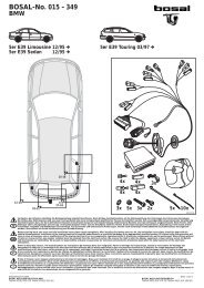
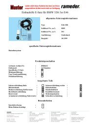
Trekhaken – Attelages – Anhängevorrichtungen – Towbars<br />
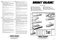
<strong>Mercedes</strong> <strong>CLS</strong> (<strong>type</strong> <strong>C219</strong>)<br />
10/2004 - ….<br />
GDW Ref. 1669T30<br />
EEC APPROVAL N°: E1 - 55R - 011867<br />
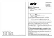
max ↓ kg<br />
X<br />
max ↓ kg<br />
D=<br />
max ↓ kg<br />
+<br />
max ↓ kg<br />
X 0.00981 < 10,70 KN<br />
S/ = 85 Kg<br />
Max. geremd / freiné / braked / gebremst = 2000 Kg<br />
Max. zonder remmen / sains freiné / without braked / ungebremst = 700 Kg<br />
GDW nv – Hoogmolenwegel 23 – B-8790 Waregem<br />
TEL. 32(0)56 60 42 12(L5) – FAX. 32(0)56 60 01 93<br />
E-Mail : gdw@gdwtowbars.com - Website : www.gdwtowbars.com
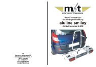
<strong>Mercedes</strong> <strong>CLS</strong> (<strong>type</strong> <strong>C219</strong>)<br />
10/2004 - ….<br />
Ref. 1669T30<br />
C C'<br />
D<br />
3<br />
B<br />
5<br />
1<br />
-p<br />
5<br />
6<br />
A<br />
B<br />
5<br />
A<br />
D<br />
6<br />
4<br />
C C'<br />
2<br />
5
<strong>Mercedes</strong> <strong>CLS</strong> (<strong>type</strong> <strong>C219</strong>)<br />
10/2004 - ….<br />
Ref. 1669T30<br />
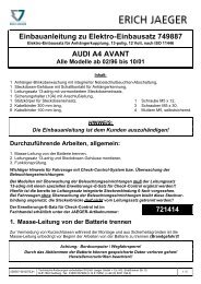
Samenstelling – Composition – Zusammenstellung<br />
4 x<br />
4 x<br />
8 x<br />
DIN 933-M12x40 -8.8<br />
DIN 933-M12x35 -8.8<br />
DIN 933-M10x35 -8.8<br />
C-C’<br />
A<br />
B<br />
GDW ref.<br />
1 x<br />
2 x<br />
8 x<br />
DIN 934-M12 -8.8<br />
DIN 934-M10 -8.8<br />
C’<br />
B<br />
GDW Ref.<br />
1 x<br />
8 x<br />
8 x<br />
DIN 128-A12-FSt<br />
DIN 128-A10-FSt<br />
A-C-C’<br />
B<br />
GDW Ref.<br />
1 x<br />
GDW ref.<br />
1 x<br />
GDW ref.<br />
4 x<br />
GDW ref.<br />
2 x<br />
1 x<br />
Verende aandrukbout<br />
M10<br />
GDW ref.<br />
(111178)<br />
2 x<br />
1 x DIN985 – M12-FSt<br />
2 x<br />
Nylon rondsel<br />
ø24x13x2,5mm<br />
GDW ref.<br />
1669<br />
1 x<br />
1 x DIN933 – M12x30<br />
Bouten – Boulons – bolts – Bolzen: Kwaliteit 8.8 DIN 912 – DIN 931 – DIN 933 – DIN 7991<br />
M6 ≡ 10,8Nm of 1,1kgm M8 ≡ 25,5Nm of 2,60kgm M10 ≡ 52,0Nm of 5,30kgm<br />
M12 ≡ 88,3Nm of 9,0kgm M14 ≡ 137Nm of 14,0kgm M16 ≡ 211,0Nm of 21,5kgm<br />
Bouten – Boulons – bolts – Bolzen: Kwaliteit 8.8 DIN 912 – DIN 931 – DIN 933 – DIN 7991<br />
M6 ≡ 13,7Nm of 1,4kgm M8 ≡ 35,3Nm of 3,6kgm M10 ≡ 70,6Nm of 7,20kgm<br />
M12 ≡ 122,6Nm of 12,5kgm M14 ≡ 194Nm of 19,8kgm M16 ≡ 299,2Nm of 30,5kgm<br />
Bouten – Boulons – bolts – Bolzen: Kwaliteit 12.9 DIN 912 – DIN 931 – DIN 933 – DIN 7991<br />
M6 ≡ 18Nm of 1,8kgm M8 ≡ 43Nm of 4,4kgm M10 ≡ 87Nm of 8,9kgm<br />
M12 ≡ 150Nm of 15,3kgm M14 ≡ 240Nm of 24,5kgm M16 ≡ 370Nm of 37,7kgm
Montagehandleiding<br />
<strong>Mercedes</strong> <strong>CLS</strong> (<strong>type</strong> <strong>C219</strong>)<br />
10/2004 - ….<br />
Ref. 1669T30<br />
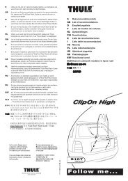
1. Demonteer de uitlaat en de bumper. Verwijder de binnenbekleding uit de kofferruimte, neem ook het<br />
kunststoffen bakje aan de linkerzijkant weg (waar de compressor in opgeborgen zit).<br />
2. Demonteer de stootbalk en verwijder definitief de stootbalksteunen.<br />
3. Verwijder in de koffer de rubbers uit de chassisbalken.<br />
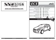
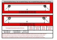
Schuif over de draagarmen (1) en (2), de kunststof dichtingen tot op de punten (B) (zie figuur<br />
onder).Schuif vervolgens de draagarmen (1) en (2) met de punten (A) in de vrijgekomen openingen<br />
achteraan de chassisbalken tot de punten (B) tegen de achterplaat komen van het voertuig, met de<br />
kunststof dichtingen tussen de draagarmen en de achterplaat. Breng bij (A) de stukjes (6) aan en bij<br />
(B) de stukjes (5), breng de nodige bouten, rondsels en moeren in en zet handvast.<br />
4. Plaats vervolgens de trekhaak tussen de draagarmen tot de punten (C) en (C’) van de trekhaak komen<br />
te passen met die van de draagarmen. Plaats aan de buitenzijde van de draagarmen de<br />
monteerstukken (3) en (4) bij. Breng de nodige bouten, rondsels en moeren in en zet handvast.<br />
Monteer de stootbalk op de positie (D) van de gemonteerde stukken (3) en (4) en breng de originele<br />
bouten terug in. Span nu alles goed aan.<br />
5. Plaats alles uit punt (1) terug op zijn oorspronkelijke plaats.<br />
Monteren van (*) en eveneens goed aanspannen.<br />
N.B.<br />
Voor de maximum toegestane massa welke uw voertuig mag trekken dient U uw dealer te raadplegen.<br />
Verwijder eventueel de bitumenlaag op de bevestigingsplaats van de trekhaak.<br />
Opgepast bij het boren dat men geen remleiding, elektriciteitsdraden of brandstofleidingen beschadigt.
<strong>Mercedes</strong> <strong>CLS</strong> (<strong>type</strong> <strong>C219</strong>)<br />
10/2004 - ….<br />
Ref. 1669T30<br />
Aanwijzingen van eigenaar van voertuig<br />
Goedkeuring van l' het span (E1 - 55R - 011867) omvat eveneens l' stijging van de gesleepte last van het<br />
voertuig op 2000kg.<br />
De nationale verordeningen van de gebruikersstaten voor de verandering van de<br />
registratiedocumenten moeten worden besproken.<br />
Element van goedkeuring van ECE - <strong>type</strong> toestemming No E1 - 55R – 011867 is de installatie van<br />
betrekking 1669T30 stijging van de gesleepte last die in verband met de procedure d' werd gecontroleerd;<br />
vergunning. Toegelaten gesleepte last (No O.1 2000kg en O.2 700kg) evenals het gewicht (85kg) (No 13)<br />
zijn als registreren.<br />
N.B.<br />
Voor de maximum toegestane massa welke uw voertuig mag trekken dient U uw dealer te raadplegen.<br />
Verwijder eventueel de bitumenlaag op de bevestigingsplaats van de trekhaak.<br />
Opgepast bij het boren dat men geen remleiding, elektriciteitsdraden of brandstofleidingen beschadigt.
<strong>Mercedes</strong> <strong>CLS</strong> (<strong>type</strong> <strong>C219</strong>)<br />
10/2004 - ….<br />
Ref. 1669T30<br />
Notice de montage<br />
1) Démonter l’échappement et le pare-chocs. Enlever la couverture intérieure du coffre, enlever aussi le<br />
baquet de plastique au côté gauche (où le compresseur est caché).<br />
2) Démonter le butoir en enlever définitivement les supports-butoir.<br />
3) Enlever les caoutchous des poutres de châssis dans le coffre.<br />
Glisser au-dessus des bras-porteur (1) et (2) les bouchons en matière plastique jusque sur les points<br />
(B)(. la figure voir en bas) Glisser les bras-porteur (1) et (2) avec les points (A) dans les trous libérés<br />
derrière les poutres de châssis jusque les points (B) s’adaptent à la plaque arrière de la voiture, avec<br />
les bouchons en matière plastique entre les bras-porteur et la plaque-arrière. Introduire en (A) les<br />
pièces de montage (6) en au point (B) les pièces de montage (5), introduire les boulons, rondelles et<br />
écrous nécessaires, mais ne les serrer pas encore.<br />
4) Placer l’attelage entre les bras-porteur jusque les points (C) et (C’) de l’attelage s’adaptent à ceux des<br />
pièces de montage. Placer à l’extérieur des bras-porteur les pièces de montage (3) et (4). Introduire<br />
les boulons, rondelles et écrous nécessaires, mais ne les serrer pas. Monter le butoir au point (D) des<br />
pièces montées (3) et (4) et introduire de nouveau les boulons originaux. Fixez bien le tout.<br />
5) Replacer les pièces de point (1) en place.<br />
Monter le (*) et bien serrer le tout.<br />
Remarque<br />
Pour le poids de traction maximum autorisé de votre voiture, consulter votre concessionaire.<br />
Enlever la couche de bitume ou d’anti-tremblement qui recouvre éventuellement les points de fixation.<br />
Veiller en percant à ne pas endommager les conduites de frein et de carburant
<strong>Mercedes</strong> <strong>CLS</strong> (<strong>type</strong> <strong>C219</strong>)<br />
10/2004 - ….<br />
Ref. 1669T30<br />
Indications de propriétaire de véhicule<br />
L'approbation de l'attelage (E1 - 55R - 011867) comprend aussi l'augmentation de la charge remorquée du<br />
véhicule sur 2000kg.<br />
Les dispositions nationales des États d'utilisateur à la modification des papiers du<br />
véhicule doivent être considérées.<br />
Élément de la ECE approbation de <strong>type</strong> No E1 - 55R – 011867 l'installation de relation 1669T30 est<br />
l'augmentation de la charge remorquée qui a été vérifiée dans le cadre de la procédure d'autorisation. La<br />
charge remorquée (No O.1 2000kg et O.2 700kg) ainsi que le poids admise (85kg) (No 13) sont si<br />
enregistrer.<br />
Remarque<br />
Pour le poids de traction maximum autorisé de votre voiture, consulter votre concessionaire.<br />
Enlever la couche de bitume ou d’anti-tremblement qui recouvre éventuellement les points de fixation.<br />
Veiller en percant à ne pas endommager les conduites de frein et de carburant
Fitting instructions<br />
<strong>Mercedes</strong> <strong>CLS</strong> (<strong>type</strong> <strong>C219</strong>)<br />
10/2004 - ….<br />
Ref. 1669T30<br />
1) Remove the exhaust and the bumper. Remove the coverings in the trunk, also remove the plastic cup<br />
(where the compressor is hidden).<br />
2) Remove the buffer beam and permanently remove the buffer beam supports.<br />
3) Remove the rubbers from the chassis beams in the trunk.<br />
Shove the plastic caps over the carrying arms (1) and (2) till on points (B)( figure see below).<br />
Slide the mounting pieces (1) and (2) with points (A) in the free holes at the back of the chassis<br />
beams till points (B) come against the backplate of the vehicle with the plastic caps between the<br />
carrying arms and the rear plate. Insert the mounting pieces (6) at point (A) and mounting pieces (5)<br />
at point (B), insert the necessary bolts, washers and nuts, but do not tighten them.<br />
4) Place the tow bar in between the mounting pieces till points (C) and (C’) of the tow bar fit those of<br />
the mounting pieces. Add the mounting pieces (3) and (4) to the outside of the mounting pieces.<br />
Insert the necessary bolts, washers and nuts but do not tighten them.<br />
Install the buffer beam on point (D) of the mounted pieces (3) and (4) and reinsert the original bolts.<br />
Tighten everything firmly.<br />
5) Put everything of point 1 back on its place.<br />
Install the (*) and also tighten firmly<br />
Note<br />
Please consult your cardealer or owners manual for the maximal permissable towing mass.<br />
Remove any bitumen coating on the fastening position for the tow bar.<br />
When drilling, be carefull not to damage any brake lines, electrical wiring or fuel lines.
<strong>Mercedes</strong> <strong>CLS</strong> (<strong>type</strong> <strong>C219</strong>)<br />
10/2004 - ….<br />
Ref. 1669T30<br />
Instructions for the vehicle owner<br />
The permission of the towbar (E1 - 55R - 011867) contains also the increase of the trailer weight of the<br />
vehicle on 2000kg.<br />
The national regulations of the user states for the change of the registration<br />
papers are to be considered.<br />
A component of the ECE – <strong>type</strong> permission No. E1 - 55R – 011867 the connecting mechanism 1669T30 is<br />
the increase of the trailer weight, which was checked in the context of the licensing procedure with. In<br />
addition must in the car license the trailer weight (No. O.1 2000kg and O.2 700kg) as well as the permissible<br />
trailer hitch tongue load (85kg) (No. 13) are to be registered if.<br />
Note<br />
Please consult your cardealer or owners manual for the maximal permissable towing mass.<br />
Remove any bitumen coating on the fastening position for the tow bar.<br />
When drilling, be carefull not to damage any brake lines, electrical wiring or fuel lines.
Anbauanleitung<br />
<strong>Mercedes</strong> <strong>CLS</strong> (<strong>type</strong> <strong>C219</strong>)<br />
10/2004 - ….<br />
Ref. 1669T30<br />
1. Den Auspuff <strong>und</strong> die Stoβstange abmontieren. Die Innenverkleidung aus dem Kofferraum entfernen,<br />
auch das Ablagefach an der linken Seite entfernen (wo der Kompressor versteckt ist).<br />
2. Die Stoβstange abmontieren <strong>und</strong> die Stoβbalkenstütze endgültig entfernen.<br />
3. In dem Kofferraum den Gummi aus aus den Rahmenbalken entfernen.<br />
Die Kunststoffabdichtungen bis auf Punkte (B), über die Tragarme (1) <strong>und</strong> (2) schieben.(Figur unten zu<br />
sehen)<br />
Die Tragarme (1) <strong>und</strong> (2) mit den Punkten (A) auf die freigewordenen Löcher hinten in den<br />
Rahmenbalken (Chassis) schieben, bis die Punkte (B) gegen das Karosserieheckblech vom Wagen<br />
kommen, mit den Kunststoffabdichtungen zwischen den Tragarmen <strong>und</strong> dem Karosserieheckblech. Die<br />
Contraplatten (6) bei den Punkten (A) anbringen <strong>und</strong> die Contraplatten (5) bei Punkt (B), Bolzen,<br />
Sicherungsscheiben <strong>und</strong> Muttern einbringen ohne festzuziehen.<br />
4. Die Anhängerkupplung zwischen die Tragarme setzen, bis die Punkte (C) <strong>und</strong> (C’) von der<br />
Anhängerkupplung mit den Punkten der Tragarme übereinstimmen. An der Auβenseite der Tragarme<br />
die Montierstücke (3) <strong>und</strong> (4) beisetzen. Bolzen, Sicherheitsscheiben <strong>und</strong> Muttern einbringen ohne<br />
festzuziehen.<br />
Den Stoβbalken auf Punkt (D) der Montierstücke (3) <strong>und</strong> (4) montieren <strong>und</strong> die originalen Bolzen<br />
wieder einbringen. Alles entsprechend der Drehmomentenvorgabe festziehen.<br />
5. Alles von Punkt (1) wieder Verbauen. (*) montieren <strong>und</strong> auch entsprechend der Drehmomentenvorgabe<br />
festziehen.<br />
Hinweise<br />
Die maximale Anhängelast ihres Fahrzeuges können Sie im Fahrzeugschein oder im Benutzerhandbuch nachlesen.<br />
Im Bereich der Anlageflächen muss der Unterbodenschutz <strong>und</strong> das Antidröhnmaterial entfernt werden.<br />
Vor dem Bohren prüfen, dass dort eventuell keine Leitungen beschädigt werden können
<strong>Mercedes</strong> <strong>CLS</strong> (<strong>type</strong> <strong>C219</strong>)<br />
10/2004 - ….<br />
Ref. 1669T30<br />
Die Berechnung des D-Wertes erfolgt folgendermaßen:<br />
D= T x R x 9,81 / (T + R) x 1000<br />
T= D x R x 1000 / (R x 9,81) – (1000 x D)<br />
R= T x D x 1000 / (T x 9,81) – (1000 x D)<br />
R – Gesamtmasse des Anhängers<br />
T – Gesamtmasse des Zugfahrzeuges in kg<br />
D – D-Wert in kN<br />
Hinweise für den Fahrzeughalter<br />
Die Genehmigung der Kupplung ( E1 - 55R – 011867) beinhaltet auch die Erhöhung der Anhängelast des<br />
Fahrzeuges auf 2000kg.<br />
Die nationalen Bestimmungen der Anwenderstaaten zur Änderung der<br />
Fahrzeugpapiere sind zu beachten.<br />
Bestandteil der ECE - Typgenehmigung Nr. E1 - 55R – 011867 der Verbindungseinrichtung 1669T30<br />
ist die Erhöhung der Anhängelast, welche im Rahmen des Genehmigungsverfahrens mit abgeprüft wurde.<br />
Die Anhängelast (Nr. O.1 2000kg <strong>und</strong> O.2 700kg) sowie die zulässige Stützlast (85kg) (Nr. 13) sind wenn<br />
einzutragen.<br />
Hinweise<br />
Die maximale Anhängelast ihres Fahrzeuges können Sie im Fahrzeugschein oder im Benutzerhandbuch nachlesen.<br />
Im Bereich der Anlageflächen muss der Unterbodenschutz <strong>und</strong> das Antidröhnmaterial entfernt werden.<br />
Vor dem Bohren prüfen, dass dort eventuell keine Leitungen beschädigt werden können
<strong>Mercedes</strong> <strong>CLS</strong> (<strong>type</strong> <strong>C219</strong>)<br />
10/2004 - ….<br />
Ref. 1669T30<br />
6x moren M6 in de koffer achter<br />
6x boulons M6 dans le coffre<br />
6x nuts M6 in the trunk<br />
6x Mutter M6 im Kofferraum<br />
2x bout SW 10mm<br />
2x écrous SW 10mm<br />
2x bolt SW 10mm<br />
2x Blechtreiber SW 10mm<br />
Hinweise<br />
Die maximale Anhängelast ihres Fahrzeuges können Sie im Fahrzeugschein oder im Benutzerhandbuch nachlesen.<br />
Im Bereich der Anlageflächen muss der Unterbodenschutz <strong>und</strong> das Antidröhnmaterial entfernt werden.<br />
Vor dem Bohren prüfen, dass dort eventuell keine Leitungen beschädigt werden können
<strong>Mercedes</strong> <strong>CLS</strong> (<strong>type</strong> <strong>C219</strong>)<br />
10/2004 - ….<br />
Ref. 1669T30<br />
2x bout SW 10mm<br />
2x écrous SW 10mm<br />
2x bolt SW 10mm<br />
2x Blechtreiber SW 10mm<br />
2x moren M6<br />
2x boulons M6<br />
2x nuts M6<br />
2x Mutter M6<br />
1x bout SW 10mm<br />
1x écrous SW 10mm<br />
1x bolt SW 10mm<br />
1x Blechtreiber SW 10mm<br />
1x plastiekplug<br />
1x rivet en plastique<br />
1x plastic rivet<br />
1x Clip<br />
Hinweise<br />
Die maximale Anhängelast ihres Fahrzeuges können Sie im Fahrzeugschein oder im Benutzerhandbuch nachlesen.<br />
Im Bereich der Anlageflächen muss der Unterbodenschutz <strong>und</strong> das Antidröhnmaterial entfernt werden.<br />
Vor dem Bohren prüfen, dass dort eventuell keine Leitungen beschädigt werden können
<strong>Mercedes</strong> <strong>CLS</strong> (<strong>type</strong> <strong>C219</strong>)<br />
10/2004 - ….<br />
Ref. 1669T30<br />
1x bout SW 10mm<br />
1x écrous SW 10mm<br />
1x bolt SW 10mm<br />
1x Blechtreiber SW 10mm<br />
1x more M6<br />
1x boulon M6<br />
1x nut M6<br />
1x Mutter M6<br />
2x plastiekplug<br />
2x rivet en plastique<br />
2x plastic rivet<br />
2x Clip<br />
2x moren M6, Torx T30<br />
2x boulons M6, Torx T30<br />
2x nuts M6, Torx T30<br />
2x Mutter M6, Torx T30<br />
Hinweise<br />
Die maximale Anhängelast ihres Fahrzeuges können Sie im Fahrzeugschein oder im Benutzerhandbuch nachlesen.<br />
Im Bereich der Anlageflächen muss der Unterbodenschutz <strong>und</strong> das Antidröhnmaterial entfernt werden.<br />
Vor dem Bohren prüfen, dass dort eventuell keine Leitungen beschädigt werden können
<strong>Mercedes</strong> <strong>CLS</strong> (<strong>type</strong> <strong>C219</strong>)<br />
10/2004 - ….<br />
Ref. 1669T30<br />
Geleverd met - Livré avec<br />
Delivered with - Geliefert mit<br />
T30<br />
1 afneembare kit T30<br />
1 kit escamotable T30<br />
1 kit escamotable T30<br />
1 abnehmbares Kit T30<br />
Hinweise<br />
Die maximale Anhängelast ihres Fahrzeuges können Sie im Fahrzeugschein oder im Benutzerhandbuch nachlesen.<br />
Im Bereich der Anlageflächen muss der Unterbodenschutz <strong>und</strong> das Antidröhnmaterial entfernt werden.<br />
Vor dem Bohren prüfen, dass dort eventuell keine Leitungen beschädigt werden können
<strong>Mercedes</strong> <strong>CLS</strong> (<strong>type</strong> <strong>C219</strong>)<br />
10/2004 - ….<br />
Ref. 1669T30<br />
Fig.1
<strong>Mercedes</strong> <strong>CLS</strong> (<strong>type</strong> <strong>C219</strong>)<br />
10/2004 - ….<br />
Ref. 1669T30<br />
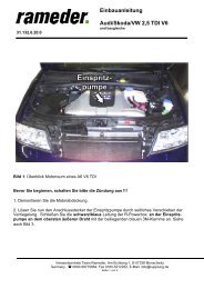
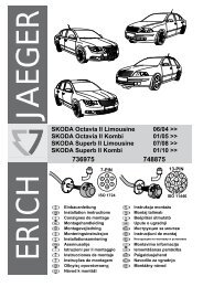
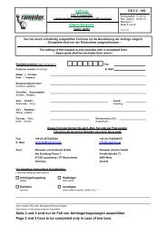
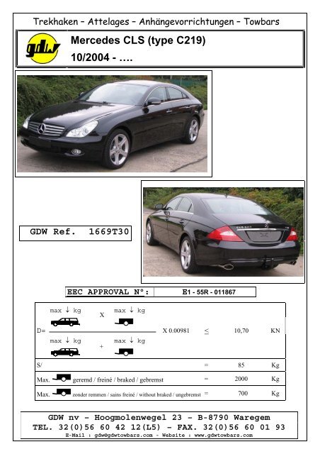
Monteren stekkerdooshouder<br />
1) Draai de verende aandrukbout M10 in de opgelaste moer van de priseplaat volgens figuur 1.<br />
Zorg ervoor dat enkel nog het kogeltje boven de priseplaat uitkomt.<br />
2) Monteer vervolgens de priseplaat met de bout M12x30, plaats een nylon rondsel tussen de<br />
priseplaat en het voetstuk, en één tussen de priseplaat en de borgmoer M12 (figuur 2). Draai<br />
de borgmoer op maar zorg ervoor dat de priseplaat nog kan verdraaien.<br />
3) Regel de verende aandrukbout tot de bout bijna tegen de bevestigingssteun komt.<br />
Figuur 3 en 4 tonen de priseplaat in de ‘verborgen’- en de ‘gebruiks’-stand<br />
Montage du porteur multiprise<br />
1) Visser le poussoir à ressort M10 dans l’écrou soudé de la plaque de prise selon figure 1, de<br />
sorte que seule le goujon dépasse de la plaque.<br />
2) Monter la plaque de prise avec le boulon M12x30, placer une rondelle de nylon entre la<br />
plaque de prise et le pied et une entre la plaque de prise et l’écrou de sûreté M12 (figure 2).<br />
Visser l’écrou de sécurité, mais de façon à ce que la plaque de prise puisse être déplacée.<br />
3) Régler le poussoir à ressort afin de la positionner contre le support de fixation.<br />
Les figures 3 et 4 montrent la plaque de prise en position ‘cachée’ et position ‘d’utilisation’.<br />
Remarque : le changement de position doit être effectué avec doigté
<strong>Mercedes</strong> <strong>CLS</strong> (<strong>type</strong> <strong>C219</strong>)<br />
10/2004 - ….<br />
Ref. 1669T30<br />
Assemblage of the socket plate holde<br />
1) Screw the spring press bolts M10 in the welded nut of the plug plate according to figure 1.<br />
Make sure that only the little ball comes over the plug plate.<br />
2) Mount the plug plate with bolt M12x30, place the nylon washer in between the plug plate and<br />
the fastening support of the tow bar (figure 2). Screw in the security nut but make sure that<br />
the plug plate can still move.<br />
3) Arrange the spring press bolts till the bolt almost comes against the fastening support.<br />
Figure 3 and 4 show the plug plate ‘switched on’ and ‘off’.<br />
Note : be careful when switching the positions on-off<br />
montieren von dem Steckdosenhalter<br />
1) Den Sprungfederbolzen M10 in die aufgeschweiβte Mutter von der Steckerplatte<br />
schrauben, wie in Figur 1 gezeichnet. Dafür sorgen, dass nur die kleine Kugel über die<br />
Steckerplatte kommt.<br />
2) Die Steckerplatte mit dem Bolzen M12x30 montieren, das Nylonritzel zwischen die<br />
Steckerplatte <strong>und</strong> die Befestigungsstütze an der Anhängerkupplung setzen (Figur 2).<br />
Das Sicherheitsritzel hineinschrauben, aber dafür sorgen, dass die Steckerplatte noch<br />
verdreht werden kann.<br />
3) Den Sprungfederbolzen regeln, bis der Bolzen fast gegen die Befestigungsstütze<br />
kommt.<br />
Figure 3 <strong>und</strong> 4 zeigt die Steckerplatte in beiden Gebrauchsweisen: ‘versteckt’ <strong>und</strong><br />
‘tätig’.<br />
Achtung: Vorsicht beim wechseln von den Gebrauchsweisen.
<strong>Mercedes</strong> <strong>CLS</strong> (<strong>type</strong> <strong>C219</strong>)<br />
10/2004 - ….<br />
Ref. 1669T30<br />
Figuur – figure – figur 1 Figuur – figure –figur 2<br />
Figuur – figure –figur 3 Figuur – figure –figur 4
<strong>Mercedes</strong> <strong>CLS</strong> (<strong>type</strong> <strong>C219</strong>)<br />
10/2004 - ….<br />
Ref. 1669T30<br />
BELANGRIJKE RAADGEVINGEN :<br />
IN HET VOERTUIG BEWAREN<br />
Montage :<br />
- Voor aanvang van de montage dient de trekhaak gecontroleerd te worden op transport schade.<br />
- Raadpleeg aandachtig de montagehandleiding. Alle instructies dienen gevolgd te worden.<br />
- Voor de montage moet de trekhaak eerst op het voertuig gepresenteerd worden.<br />
- Bij het boren van gaten, controleren dat aanwezige bekabelingen niet beschadigd kunnen worden.<br />
Verwijder antidreun of bitumenlaag. Geboorde gaten en carrosserie onderdelen met corrosiewerende verf<br />
behandelen.<br />
- Als het voertuig geen standaard bumpers heeft (speciale serie, sportuitvoeringen, Tuning parts …), dient<br />
de uitsparingsmal gecontroleerd te worden. Neem bij twijfel contact op met GDW.<br />
De geleverde trekhaak is enkel gemonteerd voor stockering, daarom moeten alle onderdelen<br />
worden gedemonteerd!!<br />
Garantie :<br />
- De aangegeven Max. trekmassa, “D” en “S” waarde mogen niet overschreden worden.<br />
- Na 1.000.km gebruik en ten minste 1 keer per jaar hoeft de trekhaak gecontroleerd te worden :<br />
o Alle boutverbindingen controleren en bij spannen als nodig.<br />
o Beschadiging aan de verf herstellen.<br />
o Als de trekhaak door een externe belasting geraakt wordt moet deze vervangen worden.<br />
o De interne delen van het afneembaar systeem moeten ingevet worden.<br />
Gebruik :<br />
- Indien trekhaak kogel de kentekenplaat of het mistlicht geheel of gedeeltelijk bedekt MOET deze<br />
bij niet gebruik verwijderd worden.<br />
Belangrijke informatie!<br />
We willen er nadrukkelijk op wijzen dat het inbouwen van deze trekhaak kan leiden tot het vervallen van de garantie of<br />
de vrijwaringsplicht van de autofabrikant. Verder willen wij nog benadrukken dat de inbouw van de trekhaak kan<br />
leiden tot een verhoogde belasting en daardoor meer slijtage aan het voertuig.<br />
Voor de levering van de trekhaak gelden de vrijwaringsvoorwaarden zoals vermeld in onze Algemene voorwaarden<br />
(zie alinea 7, Gebrek van de zaak en garantie). De aansprakelijkheid voor schade aan andere onderdelen en<br />
gevolgschade als gevolg van gebreken in de trekhaak wordt, in zoverre deze berust op lichte nalatigheid van <strong>Rameder</strong>,<br />
wordt uitdrukkelijk uitgesloten.<br />
De klant wordt geacht bij doorverkoop van het voertuig de koper nadrukkelijk te wijzen op de hierboven genoemde<br />
prestatiebeperkingen.
<strong>Mercedes</strong> <strong>CLS</strong> (<strong>type</strong> <strong>C219</strong>)<br />
10/2004 - ….<br />
Ref. 1669T30<br />
RECOMMANDATIONS IMPORTANTES :<br />
A CONSERVER DANS LE VEHICULE<br />
Fitting :<br />
- Make sure that the tow bar has not been damage during transport and it is the right reference for the<br />
vehicle.<br />
- Read the fitting instruction before starting and follow them very precisely during the fitting.<br />
- Present the tow bar <strong>und</strong>er the car first to check if all points are right.<br />
- If holes have to be drilled, check that no wires can be damaged, remove all so<strong>und</strong>proofing material,<br />
clean and protect the drilled holes with an anticorrosive product.<br />
- If the vehicle is equipped with special bumpers (sport or tuning parts…) first contact the technical<br />
service of GDW to be sure that the tow bar can be fitted.<br />
The towbar delivered is only for storage, the parts have to be disassembled!!<br />
Guarantee :<br />
- The indicated towing weight, “D” and “S” values may not be exceeded<br />
- The tow bar has to be checked after 1.000 km and every year :<br />
o All bolts should be checked and retightened if necessary<br />
o Repair any damage to the paint finish<br />
o Replace any damaged components<br />
o Parts of the detachable tow bars must be kept well greased.<br />
Use :<br />
- If the towing ball covers the number plate or the fog light, it must always be removed when no<br />
trailer is used.<br />
Information importante !<br />
Nous signalons expressément que le montage de ce dispositif de remorquage peut entraîner l’annulation de la garantie<br />
ou de l'obligation de garantie du constructeur automobile. De plus, nous indiquons que le montage du dispositif de<br />
remorquage peut entraîner une sollicitation plus élevée donc une usure plus importante du véhicule.<br />
Les conditions de garantie selon nos conditions générales de vente s’appliquent pour la livraison du dispositif de<br />
remorquage (voir Art. 7 Vices matériel et garantie). La responsabilité pour des dommages sur d’autres pièces et des<br />
dommages consécutifs à des défauts sur le dispositif de remorquage est expressément exclue, dans la mesure où elle est<br />
fondée sur la négligence légère de <strong>Rameder</strong>.<br />
En cas de revente du véhicule, le client doit informer expressément l’acheteur des limitations précédemment décrites.
<strong>Mercedes</strong> <strong>CLS</strong> (<strong>type</strong> <strong>C219</strong>)<br />
10/2004 - ….<br />
Ref. 1669T30<br />
GENERAL INSTRUCTIONS:<br />
MUST BE KEPT IN THE VEHICLE<br />
Fitting :<br />
- Make sure that the tow bar has not been damage during transport and it is the right reference<br />
for the vehicle.<br />
- Read the fitting instruction before starting and follow them very precisely during the fitting.<br />
- Present the tow bar <strong>und</strong>er the car first to check if all points are right.<br />
- If holes have to be drilled, check that no wires can be damaged, remove all so<strong>und</strong>proofing<br />
material, clean and protect the drilled holes with an anticorrosive product.<br />
- If the vehicle is equipped with special bumpers (sport or tuning parts…) first contact the<br />
technical service of GDW to be sure that the tow bar can be fitted.<br />
Guarantee :<br />
- The indicated towing weight, “D” and “S” values may not be exceeded<br />
- The tow bar has to be checked after 1.000 km and every year :<br />
o All bolts should be checked and retightened if necessary<br />
o Repair any damage to the paint finish<br />
o Replace any damaged components<br />
o Parts of the detachable tow bars must be kept well greased.<br />
Use :<br />
- If the towing ball covers the number plate or the fog light, it must always be removed<br />
when no trailer is used.<br />
Important Information!<br />
We wish to expressly draw to your attention that installing this trailer hitch can lead to loss of the guarantee or the<br />
vehicle producer’s warranty obligations. We also advise you that installing the trailer hitch can lead to greater stress<br />
and strain and hence to greater vehicle wear and tear.<br />
The general terms of warranty according to the General Term of Business apply for the delivery of the trailer hitch (see<br />
No. 7 Material Defects and Guarantee). Liability for damage to other parts and consequential damage due defects of<br />
the trailer hitch is expressly excluded as far as minor negligence on the part of <strong>Rameder</strong> is involved.<br />
The customer is also expressly advised to inform the purchaser of the vehicle of aforesaid limitations.
<strong>Mercedes</strong> <strong>CLS</strong> (<strong>type</strong> <strong>C219</strong>)<br />
10/2004 - ….<br />
Ref. 1669T30<br />
WICHTIGE RATSCHLÄGE :<br />
IM FAHRZEUG BEWAHREN<br />
Montage :<br />
- Vor Anfang der Montage muss die Anhängerkupplung auf Transportschäden kontrolliert<br />
werden.<br />
- Aufmerksam die Anbauanleitung zu Rate ziehen. Alle Anweisungen sollen beachtet werden<br />
- Erst die Anhängerkupplung <strong>und</strong> das Fahrzeug kontrollieren, danach montieren.<br />
- Vor dem Bohren der Löcher prüfen, ob vorhandene Kabel nicht beschädigt werden können.<br />
Dröhnschutz <strong>und</strong> Unterbodenschutz entfernen. Gebohrte Löcher <strong>und</strong> Karosserieunterteile mit<br />
einer korrosionsfesten Farbe behandeln.<br />
- Falls das Fahrzeug keine Standardstoßstangen hat (spezielle Serie, Sportausführungen, Tuning<br />
…), muss die Aussparung nachgeprüft werden. Im Zweifelsfall, GDW kontaktieren.<br />
Die gelieferte Anhängerkupplung ist für die Lagerung montiert, bitte die Unterteile<br />
abmontieren!!!<br />
Garantie :<br />
- Die angegeben max. Anhängelast, “D” <strong>und</strong> “S” Wert, darf nicht überschritten werden.<br />
- Nach 1.000 Km Gebrauch <strong>und</strong> wenigstens 1 mal pro Jahr muss die Anhängerkupplung<br />
nachgeprüft werden :<br />
o Alle Bolzenverbindungen nachprüfen <strong>und</strong> nachziehen falls nötig.<br />
o Beschädigungen an der Farbe ausbessern.<br />
o Falls die Anhängerkupplung durch eine extreme Belastung beschädigt wurde, muss diese<br />
ersetzt werden.<br />
o Das innere Teil vom abnehmbaren System einfetten.<br />
Gebrauch :<br />
- Falls die Kugel von der Anhängerkupplung das Kennzeichen oder den Nebelscheinwerfer ganz<br />
oder zum Teil verdeckt, muss diese bei Nichtgebrauch entfernt werden.<br />
Wichtige Information!<br />
Wir weisen ausdrücklich darauf hin, dass der Einbau dieser Anhängerzugvorrichtung zum Verlust der Garantie bzw.<br />
der Gewährleistungspflicht des Fahrzeugherstellers führen kann. Es wird ferner ausdrücklich darauf hingewiesen, dass<br />
der Einbau der Anhängerzugvorrichtung zu einer höheren Beanspruchung <strong>und</strong> Belastung <strong>und</strong> damit zu einem höheren<br />
Verschleiß am Fahrzeug führen kann.<br />
Für die Lieferung der Anhängerzugvorrichtung gelten die Gewährleistungsbedingungen gemäß unseren Allgemeinen<br />
Geschäftsbedingungen (siehe Ziff. 7 Sachmängel <strong>und</strong> Garantie). Die Haftung für Schäden an anderen Teilen <strong>und</strong><br />
Folgeschäden aufgr<strong>und</strong> von Mängeln an der Anhängerzugvorrichtung wird, soweit sie auf leichter Fahrlässigkeit von<br />
<strong>Rameder</strong> beruht, ausdrücklich ausgeschlossen.<br />
Der K<strong>und</strong>e wird bei einer Weiterveräußerung des Fahrzeugs den Käufer auf die vorstehend beschriebenen<br />
Einschränkungen ausdrücklich hinweisen.
<strong>Mercedes</strong> <strong>CLS</strong> (<strong>type</strong> <strong>C219</strong>)<br />
10/2004 - ….<br />
Ref. 1669T30<br />
De tussenruimte conform supplement 7, afbeelding 25a; 25b van<br />
de richtlijn ECE 55 moet in acht worden genomen.<br />
La zone de dégagement doit être garantie conformément à l’annexe<br />
7, illustration 25a; 25b de la directive ECE 55.<br />
The clearance specified in appendix 7, diagram 25a; 25b of<br />
guideline ECE 55 must be guaranteed.<br />
Der Freiraum nach Anhang 7, Abbildung 25a; 25b der Richtlinie<br />
ECE 55 ist zu gewährleisten.<br />
Bij toelaatbaar totaal gewicht van het voertuig<br />
Pour poids total en charge autorisé du véhicle<br />
At laden weight of the vehicle<br />
Bei zulässigem Gesamtgewicht des Fahrzeuges
Kraftfahrt-B<strong>und</strong>esamt<br />
DE-24932 Flensburg<br />
E 1<br />
MITTEILUNG<br />
ausgestellt von:<br />
Kraftfahrt-B<strong>und</strong>esamt<br />
über die Erweiterung der Genehmigung<br />
für einen Typ einer mechanischen Verbindungseinrichtung oder eines<br />
mechanischen Verbindungsbauteils nach der Regelung Nr. 55<br />
COMMUNICATION<br />
issued by:<br />
Kraftfahrt-B<strong>und</strong>esamt<br />
concerning approval extended<br />
of a <strong>type</strong> of mechanical coupling device or component pursuant to<br />
Regulation No. 55<br />
Nummer der Genehmigung: 011867 Erweiterung: 02<br />
Approval No.<br />
Extension No.<br />
1. Fabrik- oder Handelsmarke der Einrichtung oder des Bauteils:<br />
Trade name or mark of the device or component:<br />
G.D.W.<br />
2. Herstellerbezeichnung für den Typ der Einrichtung oder des Bauteils:<br />
Manufacturer’s name for the <strong>type</strong> of device or component:<br />
1669T30<br />
3. Name <strong>und</strong> Anschrift des Herstellers:<br />
Manufacturer's name and address:<br />
Konstruktiewerkhuizen Germain Deconinck n.v.<br />
BE-8790 Waregem<br />
4. Gegebenenfalls Name <strong>und</strong> Anschrift des Vertreters des Herstellers:<br />
If applicable, name and address of manufacturer's representative:<br />
rameder. Anhängerkupplungen<br />
<strong>und</strong> Autoteile GmbH & Co. KG<br />
DE-07338 Leutenberg / OT Munschwitz
Kraftfahrt-B<strong>und</strong>esamt<br />
DE-24932 Flensburg<br />
Nummer der Genehmigung: 011867, Erweiterung 02<br />
Approval No.:<br />
2<br />
5. Namen oder Handelsmarken anderer Lieferanten, mit denen die Einrichtung oder das<br />
Bauteil gekennzeichnet ist:<br />
Alternative supplier’s names or trade marks applied to the device or component:<br />
entfällt<br />
not applicable<br />
6. Name <strong>und</strong> Anschrift des Unternehmens oder der Gesellschaft, die für die<br />
Übereinstimmung der Produktion verantwortlich ist:<br />
Name and address of company or body taking responsibility for the conformity of<br />
production:<br />
Konstruktiewerkhuizen Germain Deconinck n.v.<br />
BE-8790 Waregem<br />
7. Zur Genehmigung vorgelegt am:<br />
Submitted for approval on:<br />
20.06.2012<br />
8. Technischer Dienst, der die Prüfungen für die Genehmigung durchführt:<br />
Technical service responsible for conducting approval tests:<br />
TÜV SÜD AUTOMOTIVE GmbH<br />
DE-80686 München<br />
9. Kurzbeschreibung:<br />
Brief description:<br />
9.1. Typ <strong>und</strong> Klasse der Einrichtung oder des Bauteils:<br />
Type and class of device or component:<br />
nicht genormte Kupplungskugel der Klasse A50-X<br />
non-standard coupling ball pursuant to class A50-X<br />
9.2. Kennwerte:<br />
Characteristic values:<br />
9.2.1. Hauptwerte:<br />
Primary values:<br />
D = 10,70 kN<br />
S = 85 kg<br />
Alternativwerte:<br />
Alternative values:<br />
entfällt<br />
not applicable
Kraftfahrt-B<strong>und</strong>esamt<br />
DE-24932 Flensburg<br />
Nummer der Genehmigung: 011867, Erweiterung 02<br />
Approval No.:<br />
3<br />
9.3. Bei mechanischen Verbindungseinrichtungen oder –bauteilen der Klasse A,<br />
einschließlich Kupplungshalterungen:<br />
For Class A mechanical coupling devices or components, including towing brackets:<br />
Höchstzulässige Fahrzeugmasse gemäß Fahrzeugherstellerangaben:<br />
Vehicle manufacturer’s maximum permissible vehicle mass:<br />
2370 kg<br />
Verteilung der höchstzulässigen Fahrzeugmasse auf die Achsen:<br />
Distribution of maximum permissible vehicle mass between axles:<br />
1165/1250 kg<br />
Höchstzulässige Anhängelast gemäß Fahrzeugherstellerangaben:<br />
Vehicle manufacturer’s maximum permissible towable trailer mass:<br />
keine Angabe<br />
no specification<br />
Bemerkung: durch den Technischen Dienst wurden folgende höchstzulässige<br />
Anhängelasten ermittelt:<br />
remark: the technical service has determined following maximum permissible<br />
towable trailer masses:<br />
2000 kg (gebremst/braked)<br />
700 kg (ungebremst/unbraked)<br />
Höchstzulässige statische Stützlast an der Kupplungskugel gemäß Fahrzeugherstellerangaben:<br />
Vehicle manufacturer’s maximum permissible static vertical load on coupling ball:<br />
keine Angabe<br />
no specification<br />
Bemerkung: durch den Technischen Dienst wurde folgende höchstzulässige<br />
statische Stützlast an der Kupplungskugel ermittelt:<br />
remark: the technical service has determined following maximum permissible<br />
static vertical load on coupling ball:<br />
85 kg<br />
Höchstmasse des betriebsbereiten Fahrzeugs mit Aufbau, einschließlich Kühlmittel,<br />
Ölen, Kraftstoff, Werkzeugen <strong>und</strong> Reserverad (falls vorhanden), aber ohne<br />
Fahrzeugführer:<br />
Maximum mass of the vehicle, with bodywork, in running order, including coolant, oils,<br />
fuel, tools and spare wheel (if supplied) but not including driver:<br />
1905 kg
Kraftfahrt-B<strong>und</strong>esamt<br />
DE-24932 Flensburg<br />
Nummer der Genehmigung: 011867, Erweiterung 02<br />
Approval No.:<br />
4<br />
Beladungszustand, bei dem bei Fahrzeugen der Klasse M1 die Höhe der Kupplungskugel<br />
einer mechanischen Verbindungseinrichtung über dem Boden zu messen ist –<br />
siehe Abschnitt 2 der Anlage 1 zum Anhang 7:<br />
Loding condition <strong>und</strong>er which the tow ball height of a mechanical coupling device fitted<br />
to category M1 vehicles is to be measured – see paragraph 2 of annex 7, appendix 1:<br />
Achslastverteilung gemäß zulässiger Gesamtmasse nach Herstellerangaben<br />
axle load distribution in accordance with permitted total mass acc. to<br />
manufacturer's data<br />
10. Anweisungen des Fahrzeugherstellers für den Anbau der Verbindungseinrichtung oder<br />
des Verbindungsbauteils an das Fahrzeug <strong>und</strong> Fotografien oder Zeichnungen der<br />
Befestigungspunkte:<br />
Instructions for the attachment of the coupling device or component <strong>type</strong> to the vehicle<br />
and photographs or drawings of the mounting points given by the vehicle manufacturer:<br />
siehe Montage- <strong>und</strong> Betriebsanleitung<br />
see installation and operating instructions<br />
11. Angaben über die Befestigung besonderer Verstärkungshalterungen oder –platten oder<br />
Abstandhalter, die für den Anbau der Verbindungseinrichtung oder des Verbindungsbauteils<br />
erforderlich sind:<br />
Information on the fitting of any special reinforcing brackets or plates or spacing<br />
components necessary for the attachment of the coupling device or component:<br />
siehe Montage- <strong>und</strong> Betriebsanleitung<br />
see installation and operating instructions<br />
12. Zusätzliche Angaben für den Fall, dass die Verwendung der Verbindungseinrichtung<br />
oder des Verbindungsbauteils auf bestimmte Fahrzeug<strong>type</strong>n eingeschränkt ist – siehe<br />
3.4. des Anhangs 5:<br />
Additional information where the use of the coupling device or component is restricted to<br />
special <strong>type</strong>s of vehicles – see annex 5, paragraph 3.4.<br />
<strong>Mercedes</strong> <strong>CLS</strong> <strong>C219</strong><br />
(ab Baujahr 10.2004/ model year from 10.2004)<br />
13. Bei Hakenkupplungen der Klasse K: genaue Angaben zu den Zugösen, die für die<br />
Verwendung mit dem jeweiligen Hakentyp geeignet sind:<br />
For Class K hook <strong>type</strong> couplings, details of the drawbar eyes suitable for use with the<br />
particular hook <strong>type</strong>:<br />
entfällt<br />
not applicable<br />
14. Datum des Gutachtens:<br />
Date of test report:<br />
18.06.2012
Kraftfahrt-B<strong>und</strong>esamt<br />
DE-24932 Flensburg<br />
Nummer der Genehmigung: 011867, Erweiterung 02<br />
Approval No.:<br />
15. Nummer des Gutachtens:<br />
Number of test report:<br />
08-00390-CX-GBM-01<br />
16. Stelle, an der das Genehmigungszeichen angebracht ist:<br />
Approval mark position:<br />
Fabrikschild seitlich geklebt<br />
manufacturer´s plate bonded lateral<br />
17. Gr<strong>und</strong> (Gründe) für die Erweiterung der Genehmigung:<br />
Reason(s) for extension of approval:<br />
technische Änderungen<br />
technical modifications<br />
18. Die Genehmigung wird erweitert<br />
Approval extended<br />
5<br />
19.<br />
Ort:<br />
Place:<br />
DE-24932 Flensburg<br />
20.<br />
Datum: 06.08.2012<br />
Date:<br />
21.<br />
Unterschrift:<br />
Signature:<br />
Im Auftrag
Kraftfahrt-B<strong>und</strong>esamt<br />
DE-24932 Flensburg<br />
Nummer der Genehmigung: 011867, Erweiterung 02<br />
Approval No.:<br />
6<br />
22. Die Liste der Unterlagen, die bei der Genehmigungsbehörde hinterlegt <strong>und</strong> auf Anfrage<br />
erhältlich sind, liegt dieser Mitteilung bei.<br />
The list of documents deposited with the Administration Service which has granted<br />
approval is annexed to this communication and may be obtained on request.<br />
Verzeichnis:<br />
List of documents:<br />
1. Inhaltsverzeichnis zu den Beschreibungsunterlagen<br />
Index to the information package<br />
2. Nebenbestimmungen <strong>und</strong> Rechtsbehelfsbelehrung<br />
Collateral clauses and instruction on right to appeal<br />
3. Technischer Bericht mit Anlagen<br />
Technical report with annex
Kraftfahrt-B<strong>und</strong>esamt<br />
DE-24932 Flensburg<br />
Inhaltsverzeichnis zu den Beschreibungsunterlagen<br />
Index to the information package<br />
Zum ECE-Genehmigungsbogen Nr.: 011867, Erweiterung 02<br />
To ECE approval certificate No.:<br />
Ausgabedatum: 06.11.2008 letztes Änderungsdatum: 06.08.2012<br />
Date of issue:<br />
last date of amendment:<br />
1. Nebenbestimmungen <strong>und</strong> Rechtsbehelfsbelehrung<br />
Collateral clauses and instruction on right to appeal<br />
2. Beschreibungsmappe Nr.: Datum:<br />
Information document No.:<br />
Date:<br />
LS-94/20-1573/06 02.05.2008<br />
letztes Änderungsdatum: 02.05.2008<br />
last date of amendment:<br />
3. Prüfbericht(e) Nr.:<br />
Test report(s) No.:<br />
08-00390-CX-GBM<br />
08-00390-CX-GBM-01<br />
Datum:<br />
Date:<br />
15.10.2008<br />
18.06.2012<br />
4. Beschreibung der Änderungen:<br />
Description of the modifications:<br />
siehe Prübericht, Liste der Änderungen<br />
see test teport, List of modifications
Kraftfahrt-B<strong>und</strong>esamt<br />
DE-24932 Flensburg<br />
Nr. der Genehmigung: 011867, Erweiterung 02<br />
Approval No.:<br />
- Anlage -<br />
Nebenbestimmungen <strong>und</strong> Rechtsbehelfsbelehrung<br />
Nebenbestimmungen<br />
Die Einzelerzeugnisse der reihenweisen Fertigung müssen mit den Genehmigungsunterlagen<br />
genau übereinstimmen. Die in der bisherigen Genehmigung enthaltenen Auflagen gelten<br />
auch für diese Erweiterung.<br />
Rechtsbehelfsbelehrung<br />
Gegen diese Genehmigung kann innerhalb eines Monats nach Bekanntgabe Widerspruch<br />
erhoben werden. Der Widerspruch ist beim Kraftfahrt-B<strong>und</strong>esamt, Fördestraße 16,<br />
DE-24944 Flensburg, schriftlich oder zur Niederschrift einzulegen.<br />
- Attachment -<br />
Collateral clauses and instruction on right to appeal<br />
Collateral clauses<br />
The individual production of serial fabrication must be in exact accordance with the approval<br />
documents. The requirements contained in the previous approval are also valid for this<br />
amendment.<br />
Instruction on right to appeal<br />
This approval can be appealed within one month after notification. The appeal is to be filed in<br />
writing or as a transcript at the Kraftfahrt-B<strong>und</strong>esamt, Fördestraße 16,<br />
DE-24944 Flensburg.