FOS 100w - Elcon Systemtechnik
FOS 100w - Elcon Systemtechnik
FOS 100w - Elcon Systemtechnik

Sie wollen auch ein ePaper? Erhöhen Sie die Reichweite Ihrer Titel.
YUMPU macht aus Druck-PDFs automatisch weboptimierte ePaper, die Google liebt.
fiber <strong>FOS</strong> <strong>100w</strong><br />
Faser-optisches System<br />
Fiber Optical System<br />
Kurzbedienungsanleitung<br />
Short Operating Instructions<br />
© ELCON <strong>Systemtechnik</strong> GmbH 2010 Art.-Nr. 102667
Sicherheitshinweise<br />
<strong>FOS</strong> <strong>100w</strong><br />
• Bitte lesen Sie die Warnhinweise, Sicherheitsbestimmungen sowie die Kurzbedienungsanleitung<br />
gewissenhaft durch, bevor Sie mit der Installation des <strong>FOS</strong> <strong>100w</strong> beginnen.<br />
Nur so können Sie das Gerät in seinem vollen Funktionsumfang nutzen und<br />
Schäden durch unsachgemäßen Gebrauch vermeiden (Feuer, Elektroschocks, Verletzungen<br />
usw.). Bewahren Sie die Kurzbedienungsanleitung sorgfältig auf.<br />
• Der <strong>FOS</strong> <strong>100w</strong> entspricht dem aktuellen Stand der Technik und den anerkannten<br />
sicherheitstechnischen Regeln.<br />
• Verwenden Sie beim Auspacken des Gerätes keine spitzen Gegenstände, um Beschädigungen<br />
an Gehäuse oder Kabeln zu vermeiden.<br />
• Betreiben Sie das Gerät und die mitgelieferten Teile (Kabel usw.) nur in einwandfreiem<br />
Zustand und unter strenger Beachtung der Kurzbedienungsanleitung.<br />
• Arbeiten am Gerät einschließlich Öffnen des Gerätes darf nur autorisiertes Fachpersonal<br />
durchführen. Dabei sind die ESD-Schutzmaßnahmen nach DIN 100 015 zu beachten.<br />
Außer den in diesem Handbuch beschriebenen Handlungen dürfen keine Änderungen<br />
am Gerät sowie an den mitgelieferten Teilen (Kabel usw.) vorgenommen werden.<br />
• Achtung: Gefährliche elektrische Spannungen! Vor Öffnen des Gerätes unbedingt<br />
Steckernetzteil ziehen und Anschlusskabel von den Schnittstellen entfernen!<br />
• Vermeiden Sie Arbeiten am Gerät und dessen Komponenten bei Gewittertätigkeit<br />
(Trennen und Herstellen von Kabelverbindungen).<br />
• Achten Sie beim Anschluss des Gerätes auf die richtige Netzspannung<br />
(→ Technische Daten)! Das Gerät darf nicht weiter als 1,5 Meter von der Steckdose<br />
entfernt montiert werden.<br />
• Das Gerät besitzt keine eigene Trennvorrichtung zur Unterbrechung der Spannungsversorgung,<br />
da es für Dauerbetrieb ausgelegt ist. Achten Sie daher darauf, dass das<br />
Steckernetzteil stets leicht zugänglich ist.<br />
• Verlegen Sie Netz- und Anschlusskabel so, dass eine Unfallgefahr durch Stolpern oder<br />
Hängen bleiben ausgeschlossen wird.<br />
• Betreiben Sie das Gerät nur im Temperaturbereich zwischen 0°C und +45°C!<br />
• Schützen Sie das Gerät vor direkter Sonneneinstrahlung und vor Feuchtigkeit.<br />
• Wenn Sie das Gerät aus einer kalten Umgebung in eine wärmere Umgebung bringen,<br />
dann kann dies zu einer Betauung des Gerätes führen. Betaute Geräte dürfen nicht in<br />
Betrieb genommen werden. Warten Sie mit der Inbetriebnahme, bis das Gerät trocken<br />
ist.<br />
• An den Schnittstellen des Modems dürfen nur Geräte angeschlossen werden, die die<br />
elektrischen Sicherheitsbestimmungen nach EN 60950 erfüllen und das CE-Zeichen<br />
tragen.<br />
• Alle angeschlossenen Geräte müssen passende Steckverbindungen besitzen, anderenfalls<br />
sind geeignete Adapter zu verwenden.<br />
• Alle angeschlossenen Geräte dürfen nur an den vorgesehenen Schnittstellen betrieben<br />
werden.<br />
• Beachten Sie die Installations- und Sicherheitshinweise und halten Sie diese ein.<br />
Version: 2010/08/13
<strong>FOS</strong> <strong>100w</strong><br />
• Warnung vor gefährlicher Laserstrahlung - Laser Klasse 1<br />
Die zugängliche Laserstrahlung ist unter vernünftigerweise vorhersehbaren Bedingungen<br />
ungefährlich, da die Laser bei bestimmungsgemäßem Gebrauch so eingekapselt<br />
sind, dass ein Austritt von Strahlung vollständig verhindert wird. Um irreparablen Augenschäden<br />
vorzubeugen, blicken Sie niemals direkt oder indirekt (z.B. über Spiegel)<br />
in den Laserstrahl, d.h. auf das Ende des Glasfaserkabels bzw. des entsprechenden<br />
Steckverbinders. Um ein unbeabsichtigtes Hineinsehen in den Laserstrahl zu vermeiden,<br />
sind offene Kabelenden bzw. Steckverbinder grundsätzlich mit einer Staubschutzkappe<br />
zu verschließen und im Laserbereich gut reflektierende Flächen abzudecken<br />
oder zu entfernen.<br />
Um die hervorragenden Übertragungseigenschaften von Glasfaserkabel zu erhalten,<br />
darf dieses nicht geknickt werden. Um ein Knicken des Glasfaserkabels zu vermeiden,<br />
ist es in die vorgesehene Aufwickelvorrichtung einzulegen. Es darf ein Umlenkradius<br />
von 60 mm bzw. der kleinste zulässige Biegeradius von 30 mm nicht unterschritten<br />
werden. Siehe hierzu auch die TS 0011/02.96 (Schaltkabel für Fernmeldelinien; Glasfaser-Schaltkabel<br />
der Ausführung SVH mit Einmodenfaser). Des Weiteren sind offene<br />
Kabelenden und Steckverbinder mit einer Staubschutzkappe zu versehen, um Verschmutzung<br />
und damit verbundene zusätzliche Dämpfung zu vermeiden. Aus diesem<br />
Grund ist auch das Berühren der Faserendflächen zu unterlassen. Die eventuell notwendige<br />
Reinigung der Glasfasersteckverbinder sollte mit speziell dafür bestimmten<br />
Reinigungspads und -materialien erfolgen. Verwenden Sie niemals Druck- oder Atemluft,<br />
um Verunreinigungen wegzublasen, damit diese nicht in die Augen oder in die<br />
Lunge gelangen.<br />
Sehr geehrte Kundin, sehr geehrter Kunde,<br />
mit dem ELCONnect fiber <strong>FOS</strong> <strong>100w</strong> haben Sie ein Gerät erhalten, welches nach dem neuesten<br />
Stand der Technik entwickelt und unter höchsten Anforderungen gefertigt wurde.<br />
Sollte einmal etwas nicht wie beschrieben funktionieren, nehmen Sie bitte mit Ihrem Anbieter<br />
oder Händler Kontakt auf, von dem Sie dieses Gerät erworben haben. Dieser verfügt über die<br />
notwendigen Fachkenntnisse und wird Ihnen gern weiterhelfen.<br />
Wir wünschen Ihnen viel Freude mit Ihrem <strong>FOS</strong> <strong>100w</strong>.<br />
Version: 2010/08/13 1
Safety precautions<br />
2<br />
<strong>FOS</strong> <strong>100w</strong><br />
• Please read carefully the warnings and safety precautions in this operating manual before<br />
you start installation of your <strong>FOS</strong> <strong>100w</strong>. These instructions enable you to use the<br />
full functionality of the device and to avoid damage which may result from improper<br />
use (fire, electric shock, injuries etc.). Keep this manual at a safe place.<br />
• The <strong>FOS</strong> <strong>100w</strong> has been manufactured according to state-of-the-art technology and<br />
complies with the generally accepted safety standards.<br />
• Do not use sharp-edged tools for unpacking the device: they could damage cables or<br />
the enclosure.<br />
• The device and its accessories (cable etc.) shall be operated only in faultless condition,<br />
while strictly observing these operating instructions.<br />
• Only authorized personnel are allowed to open the enclosure and to carry out interventions<br />
in the device. Please observe the protective measures with respect to electrostatic<br />
discharge as per DIN 100 015. Manipulations on the modem or attached parts (cables<br />
etc.) other than those described in this manual are not allowed.<br />
• Warning: Dangerous electric voltage! Before opening the modem, remove the plug-in<br />
power supply unit and disconnect the cables from the interfaces!<br />
• Refrain from interventions in the modem and its parts during thunderstorms (in particular,<br />
avoid plugging and unplugging of cables).<br />
• When connecting the modem, pay attention to comply with the required mains voltage.<br />
(→ Technical data)! The device shall not be installed farther than 1.5 m from the socket.<br />
• The device has no separate switch for interrupting the power supply, since it has been<br />
designed for continuous operation. So make sure the plug-in power supply unit is always<br />
easily accessible.<br />
• Lay the power supply and connection cables in a way to prevent accidents (such as<br />
tripping over the cables).<br />
• The device shall be operated only between 0°C and +45°C.<br />
• Protect the device from direct sun radiation and extreme humidity.<br />
• When the device is taken from a cold environment into a warmer one, it may be bedewed.<br />
In this case the equipment must not be put into operation. So please wait until<br />
the modem is dry again.<br />
• Connect to the modem interfaces only such terminal devices which meet the safety requirements<br />
acc. to EN 60950 and which are labelled with the CE symbol.<br />
• The terminal devices shall have appropriate connectors; otherwise adequate adapters<br />
have to be used.<br />
• Connected equipment shall only be operated at the corresponding interfaces that have<br />
been designed for them.<br />
• Pay attention to the instructions on installation and safety and comply with them.<br />
Version: 2010/08/13
<strong>FOS</strong> <strong>100w</strong><br />
• Warning of dangerous laser radiation – Class 1 laser<br />
Subject to the reasonably foreseeable conditions, the accessible laser radiation is nonhazardous,<br />
since the laser beams during normal use are fully encapsulated which prevents<br />
them from being radiated. In order to protect your eyes from irreparable damage,<br />
do never look directly or indirectly (e.g. via mirror) into the laser beam, i.e. at the edge<br />
of the fiber cable or the related connector. To avoid accidentally looking into the laser<br />
beam, open cable ends or connectors, respectively, shall be sealed with a dust cover,<br />
while reflecting surfaces within the laser range need to be removed or covered at least.<br />
To maintain the supreme transmission performance of fiber cable, it must not be<br />
kinked. Therefore the fiber cable shall be placed in the special wind-up unit. Hereby<br />
the winding radius must not be lesser than 60 mm, with a minimum admissible bending<br />
radius of 30 mm. For this, see also the provisions in the Technical Specification<br />
TS 0011/02.96 (switching cable for telecommunication lines; SVH-type fiber switching<br />
cable with single-mode fiber). Further, open cable ends shall be protected by a<br />
dust cover, to protect them from being polluted and prevent the extra attenuation<br />
caused by this. For the same reason, do not touch the fiber ends. For cleaning the fiber<br />
connectors (if needed), special cleansing pads and materials should be applied. Do<br />
never try to blow off dust particles by using pressure air or your breath: otherwise<br />
tiniest particles could get into your eyes or the lungs.<br />
Dear Customer,<br />
Your ELCONnect fiber <strong>FOS</strong> <strong>100w</strong> is a product that represents state-of-the-art technology and<br />
has been manufactured in compliance with highest quality standards.<br />
Should it happen that something is acting up other than described, please contact your provider<br />
or salesman who has offered you the device. He will have the necessary knowledge to<br />
offer you the required support.<br />
And now enjoy your <strong>FOS</strong> <strong>100w</strong>!<br />
Version: 2010/08/13 3
Inhalt / Contents<br />
4<br />
<strong>FOS</strong> <strong>100w</strong><br />
DEUTSCH .................................................................................................................................... 5<br />
1 Technische Beschreibung des <strong>FOS</strong> <strong>100w</strong> ....................................................................... 5<br />
1.1 Anwendungsbereich ................................................................................................... 5<br />
1.2 Allgemeine Merkmale ................................................................................................ 5<br />
2 Installation ........................................................................................................................ 6<br />
2.1 Hardware-Anforderungen / Systemvoraussetzungen zur Installation des <strong>FOS</strong> <strong>100w</strong> 6<br />
2.2 Lieferumfang .............................................................................................................. 6<br />
2.3 Wahl des Montageortes / Befestigung des Gerätes .................................................... 6<br />
2.4 Anschlüsse und LEDs ................................................................................................ 7<br />
2.5 Kabelanschluss ........................................................................................................... 9<br />
2.6 Inbetriebnahme ........................................................................................................... 9<br />
2.7 Neustart und Factory-Reset ...................................................................................... 10<br />
2.8 Aktivierung / Deaktivierung WLAN ........................................................................ 10<br />
2.9 Pflege und Wartung .................................................................................................. 10<br />
2.10 Abbau des <strong>FOS</strong> <strong>100w</strong> ............................................................................................... 11<br />
3 Technische Daten ............................................................................................................ 11<br />
4 Wichtige Hinweise .......................................................................................................... 13<br />
4.1 Herstellererklärung ................................................................................................... 13<br />
4.2 Gewährleistung ......................................................................................................... 13<br />
4.3 Rechte und Warenzeichen ........................................................................................ 13<br />
ENGLISH ................................................................................................................................... 14<br />
1 Technical description of the <strong>FOS</strong> <strong>100w</strong> ........................................................................ 14<br />
1.1 Scope of application ................................................................................................. 14<br />
1.2 General characteristics ............................................................................................. 14<br />
2 Installation ...................................................................................................................... 15<br />
2.1 Hardware requirements / Minimum system requirements for installation of the<br />
<strong>FOS</strong> <strong>100w</strong> ............................................................................................................................. 15<br />
2.2 Scope of delivery ...................................................................................................... 15<br />
2.3 Selecting the place of installation / Fixing the device .............................................. 15<br />
2.4 Interfaces and LEDs ................................................................................................. 16<br />
2.5 Cable connection ...................................................................................................... 18<br />
2.6 Putting into operation ............................................................................................... 18<br />
2.7 Restart and Factory Reset ......................................................................................... 19<br />
2.8 Activation / Deactivation of WLAN ........................................................................ 19<br />
2.9 Maintenance ............................................................................................................. 19<br />
2.10 Uninstallation of the <strong>FOS</strong> <strong>100w</strong> ............................................................................... 20<br />
3 Technical data ................................................................................................................. 20<br />
4 Important notes .............................................................................................................. 22<br />
4.1 Manufacturer´s declaration ...................................................................................... 22<br />
4.2 Warranty ................................................................................................................... 22<br />
4.3 Rights and trademarks .............................................................................................. 22<br />
Version: 2010/08/13
<strong>FOS</strong> <strong>100w</strong><br />
DEUTSCH<br />
1 Technische Beschreibung des <strong>FOS</strong> <strong>100w</strong><br />
1.1 Anwendungsbereich<br />
Durch den Einsatz von Lichtwellenleiter-Teilnehmeranschlusssystemen lässt sich der Übertragungsbereich<br />
bei einer kontinuierlich hohen Datenrate erweitern.<br />
Mit dem <strong>FOS</strong> <strong>100w</strong> als Bestandteil des Faser-Optischen Systems von ELCON <strong>Systemtechnik</strong><br />
GmbH können Netzbetreiber ihren Endkunden Glasfaseranschlüsse („Fiber To The Home“ -<br />
FTTH) zu erschwinglichen Kosten anbieten. Die Entscheidung zugunsten von Standard-<br />
Ethernet als Übertragungsstandard erlaubt die Verwendung allgemein bekannter Netzrouting-<br />
Elemente. Damit wird die sanfte Migration hin zu FTTH-Netzwerken vollzogen.<br />
Im Ergebnis dessen werden dem Teilnehmer Breitband-Verbindungen mit qualitativ hochwertigen<br />
Voice-over-IP-Leistungen und max. Datenraten bis zu 100 Mbit/s bereitgestellt. Dank<br />
der integrierten Anschlüsse für analoge Telefondienste und dem 4-Port-Ethernet-Router können<br />
die Endgeräte beim Kunden problemlos angebunden werden.<br />
Die hohe Bandbreite für den Internet-Zugang bietet Endkunden daneben Optionen für attraktive<br />
Zusatzleistungen wie zum Beispiel IP-TV und Video-On-Demand.<br />
IP<br />
PSTN<br />
Internet<br />
Gateway<br />
PSTN<br />
Gateway<br />
1.2 Allgemeine Merkmale<br />
Access Switch<br />
TV (IPTV)<br />
Bild 1: Anwendungsszenario allgemein<br />
2 x POTS<br />
Ethernet<br />
100Base-T<br />
ELCONnect fiber<br />
<strong>FOS</strong> <strong>100w</strong><br />
FTTH<br />
WLAN<br />
• Fiber-CPE für Triple-Play-Dienste<br />
• Große Reichweite (bis zu 15 km) bei hoher Bandbreite (aktuell bis 100 Mbit/s)<br />
• Ethernet über Glasfaser für FTTH-Projekte<br />
• Point-To-Point Ethernet<br />
• Einsatzmöglichkeit von Standard-Routern mit MediaConverter zum Aufbau von<br />
LongDistance-Ethernet-Punkt-zu-Punkt-Verbindungen<br />
• Integrierte VoIP-Schnittstelle<br />
• Integrierter WLAN-Access-Point<br />
• Internes Fiber-Management<br />
• Wahlweise 1- oder 2-Fasersystem (SMF)<br />
• Integration in bestehende Management-Systeme via SNMP<br />
• Autokonfiguration<br />
Version: 2010/08/13 5
2 Installation<br />
6<br />
Bild 2: Blockschaltbild<br />
2.1 Hardware-Anforderungen / Systemvoraussetzungen zur Installation des<br />
<strong>FOS</strong> <strong>100w</strong><br />
<strong>FOS</strong> <strong>100w</strong><br />
• Netzsteckdose mit Nennspannung 230 V / 50 Hz<br />
• Glasfaser vom betriebsbereiten Access Switch<br />
• Laptop oder PC mit Betriebssystem Windows ® 98 SE, ME, 2000, XP; MAC; Linux<br />
und vollduplexfähiger Netzwerkkarte (Schnittstelle: 10/100Base-T); CPU: ab Pentium<br />
II ® , 500 MHz<br />
• Werkzeug (Wasserwaage, Bleistift, Bohrmaschine, Bohrer Ø 6 mm, Schraubendreher,<br />
kleine Zange)<br />
2.2 Lieferumfang<br />
WLAN<br />
802.11 b/g<br />
WLAN<br />
Access Point<br />
Fiber<br />
Ethernet<br />
Router<br />
oder<br />
Bridge<br />
Ethernet<br />
LAN<br />
• 1 <strong>FOS</strong> <strong>100w</strong> mit externem Steckernetzteil 12 V �, 1,2 A<br />
• 1 Bohrschablone<br />
• 1 Beutel mit Montagezubehör (3 Dübel, 3 Schrauben)<br />
• 2 Kabelbinder<br />
• 1 Kurzbedienungsanleitung<br />
2.3 Wahl des Montageortes / Befestigung des Gerätes<br />
2 × POTS<br />
VoIP<br />
2 × POTS<br />
Der <strong>FOS</strong> <strong>100w</strong> ist für den Einsatz in geschlossenen Räumen geeignet und muss an der Wand<br />
befestigt werden. Installieren Sie den <strong>FOS</strong> <strong>100w</strong> in der Nähe der vom Access Switch kommenden<br />
Glasfaser. Ebenso muss sich in der Nähe des <strong>FOS</strong> <strong>100w</strong> eine 230 V-Steckdose befinden.<br />
Da der <strong>FOS</strong> <strong>100w</strong> für Dauerbetrieb ausgelegt ist, befindet sich kein Netzschalter am Gerät.<br />
Die Trennung vom Stromnetz erfolgt durch Abziehen des Steckernetzteils. Achten Sie<br />
darauf, dass das Steckernetzteil stets leicht zugänglich ist.<br />
Version: 2010/08/13
<strong>FOS</strong> <strong>100w</strong><br />
Stellen Sie sicher, dass bei Wandmontage an der vorgesehenen Montagestelle keine Leitungen<br />
(Strom, Wasser, Gas, Telefon, Koaxialkabel, Glasfaser) unter Putz verlegt sind. Während<br />
des Betriebs entwickelt der <strong>FOS</strong> <strong>100w</strong> eine fühlbare, aber völlig ungefährliche Betriebstemperatur.<br />
Um eine ungehinderte Wärmeableitung zu gewährleisten, darf der <strong>FOS</strong> <strong>100w</strong> nicht in<br />
Gehäuse ohne ausreichende Wärmeableitung eingebaut werden. Ebenfalls aus diesem Grund<br />
ist das Gerät auch vor intensiver Wärmeeinwirkung, z.B. durch Heizkörper oder Sonneneinstrahlung<br />
zu schützen. Halten Sie Feuchtigkeit vom <strong>FOS</strong> <strong>100w</strong> fern. Vermeiden Sie eine sehr<br />
staubhaltige Umgebung.<br />
Die Montagehinweise finden Sie direkt auf der Bohrschablone. Drehen Sie jedoch vorerst nur<br />
die beiden mittleren Schrauben ein. Für die Montage müssen Sie den <strong>FOS</strong> <strong>100w</strong> öffnen. Achten<br />
Sie unbedingt darauf, dass das Steckernetzteil abgezogen ist, da sonst die Gefahr besteht,<br />
dass Sie spannungsführende Teile berühren. Öffnen Sie das Gerät, indem Sie mit einem<br />
Schraubendreher in die Aussparung des Oberteil-Verschlusses fahren und den Rasthaken nach<br />
innen drücken. Ziehen Sie den Oberteil-Verschluss nach unten ab. Drücken Sie nun den Rasthaken<br />
des Oberteil-Covers, welcher sich in der Blende rechts neben den RJ45-Buchsen<br />
(LAN) befindet, nach unten, schieben Sie gleichzeitig das Oberteil-Cover ein Stück nach oben<br />
und nehmen es ab. Zum Anschließen der Glasfasern (s. Kapitel 2.5) ist es noch erforderlich,<br />
die zwei Schrauben, mit denen das Gehäuse-Oberteil befestigt ist zu lösen, das Gehäuse-<br />
Oberteil nach rechts zu schieben und es ebenfalls abzunehmen. Der Glasfaserträger bleibt in<br />
jedem Fall auf dem Gehäuse-Unterteil aufgesteckt. Fädeln Sie nun die beiden im Lieferumfang<br />
enthaltenen Kabelbinder durch zwei in einer Linie liegende Aussparungen im Gehäuse-<br />
Unterteil links unten neben der Leiterplatte. Hängen Sie das Unterteil an den beiden Schrauben<br />
auf. Links oben neben der Leiterplatte finden Sie im Gehäuse-Unterteil eine Aussparung<br />
(Langloch), durch die nun das dritte Bohrloch sichtbar ist. Stecken Sie die dritte Schraube<br />
durch die Aussparung und drehen diese fest. Setzen Sie abschließend (ggf. nach Montage der<br />
Glasfaser) das Gehäuse in umgekehrter Reihenfolge wieder zusammen. Ein Betreiben des<br />
<strong>FOS</strong> <strong>100w</strong> ohne Gehäuse-Oberteil, Oberteil-Cover und Oberteil-Verschluss ist nicht zulässig.<br />
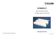
2.4 Anschlüsse und LEDs<br />
Ansicht<br />
Gehäusedurchbruch<br />
für Glasfaser<br />
WLAN-Antenne<br />
DC-Buchse<br />
RJ45-Buchsen<br />
(LAN)<br />
RJ11-Buchsen<br />
(Telefon)<br />
Oberteil-<br />
Verschluss<br />
Bild 3: Ansicht des <strong>FOS</strong> <strong>100w</strong><br />
WLAN-Antenne<br />
Oberteil-Cover<br />
Version: 2010/08/13 7<br />
Gehäuse-Oberteil<br />
LEDs<br />
WLAN-Taster<br />
Reset-Taster
Pinbelegung der RJ45-Buchse (LAN, Auto-MDI/MDIX)<br />
Pinbelegung der RJ11-Buchse ( )<br />
LED-Signalisierung<br />
8<br />
1 Tx+<br />
2 Tx-<br />
3 Rx+<br />
4 frei<br />
5 frei<br />
6 Rx-<br />
7 frei<br />
8 frei<br />
Bild 4: Pinbelegung der RJ45-Buchse<br />
<strong>FOS</strong> <strong>100w</strong><br />
1 frei<br />
2 frei<br />
3 La (Leitung a der a/b-Schnittstelle der Teilnehmeranschlussleitung)<br />
4 Lb (Leitung b der a/b-Schnittstelle der Teilnehmeranschlussleitung)<br />
5 frei<br />
6 frei<br />
Bild 5: Pinbelegung der RJ11-Buchse<br />
Das Modem verfügt über 5 LEDs, die über Stromversorgung und Aktivitäten der Datenübertragung<br />
Auskunft geben.<br />
LED „PWR“ (grün): Status Stromversorgung<br />
AN Speisespannung vorhanden<br />
AUS keine Speisespannung vorhanden<br />
LED „WLAN“ (grün): Status WLAN<br />
AN WLAN aktiviert<br />
AUS WLAN deaktiviert<br />
LED „LINK“ (grün): Status Zugangsnetz<br />
AN Verbindung zum Access Switch hergestellt<br />
BLINKT (unregelmäßig) Flackern im Takt der Datenübertragung<br />
BLINKT (1 Hz) Bootvorgang des Gerätes oder keine Verbindung<br />
zum Access Switch (Leitung unterbrochen, Dämpfung<br />
zu groß)<br />
LED „ 1“, „ 2“ (grün): Status der beiden analogen Schnittstellen<br />
AN SIP-Registrierung korrekt erfolgt, Hörer aufgelegt<br />
(onhook)<br />
BLINKT (4 Hz) keine SIP-Registrierung erfolgt<br />
BLINKT (1 Hz) Telefon bzw. anderes Endgerät klingelt<br />
AUS Hörer abgehoben (offhook); kein Nutzer vom Provider<br />
konfiguriert<br />
Version: 2010/08/13
<strong>FOS</strong> <strong>100w</strong><br />
2.5 Kabelanschluss<br />
1. Entfernen Sie Oberteil-Verschluss, Oberteil-Cover und Gehäuse-Oberteil wie im letzten<br />
Abschnitt des Kapitels 2.3 beschrieben. Das Steckernetzteil darf hierbei nicht angeschlossen<br />
sein, um eine Gefährdung durch spannungsführende Teile auszuschließen.<br />
2. Beachten Sie unbedingt die auf Seite 1 genannten Sicherheitshinweise zum Umgang<br />
mit Glasfasern und Laser Klasse 1. Verlegen Sie die Glasfasern so, dass diese nicht an<br />
Gehäusekanten eingeklemmt oder geknickt werden.<br />
Versehen Sie das Ende der vom Access Switch kommenden Glasfaser mit einem geeigneten<br />
Steckverbinder (Typ SC/PC). Führen Sie die Glasfaser durch den Freiraum<br />
links neben der Leiterplatte. Fädeln Sie die Glasfaser in mehreren ovalen Bögen auf<br />
dem Glasfaserträger ein. Stecken Sie den Glasfasersteckverbinder in die entsprechende<br />
Buchse, welche sich auf der Leiterplatte über der Telefonbuchse (RJ11) befindet. Die<br />
Glasfaser ist unmittelbar vor dem Steckverbinder mit dem Kabelhalter zu fixieren.<br />
Achten Sie darauf, dass eine sichere Zugentlastung der Glasfaser im Freiraum links<br />
neben der Leiterplatte mittels der beiden beigefügten Kabelbinder gewährleistet ist.<br />
Brechen Sie eine der Aussparungen des Oberteil-Verschlusses mit einer Zange vorsichtig<br />
aus, durch diesen Durchbruch wird die Glasfaser aus dem Gehäuse herausgeführt.<br />
3. Setzen Sie das Gehäuse wieder zusammen. Ein Betreiben des <strong>FOS</strong> <strong>100w</strong> ohne Gehäuse-Oberteil,<br />
Oberteil-Cover und Oberteil-Verschluss ist nicht zulässig.<br />
4. Verbinden Sie den <strong>FOS</strong> <strong>100w</strong> mit der Netzwerkkarte des PCs. Nutzen Sie dafür ein<br />
Ethernet-Kabel und schließen es an eine der mit „LAN“ gekennzeichneten RJ45-<br />
Buchsen des <strong>FOS</strong> <strong>100w</strong> und an die RJ45-Buchse der Netzwerkkarte an (siehe deren<br />
Anleitung).<br />
5. Ihre analogen Telefone, Faxgeräte, Anrufbeantworter, Gebührenzähler, ... schließen<br />
Sie an eine der RJ11-Buchsen an, an denen sich das Symbol „ “ befindet.<br />
6. Zuletzt verbinden Sie die Buchse „12V DC“ des <strong>FOS</strong> <strong>100w</strong> mithilfe des beiliegenden<br />
Steckernetzteils mit dem Stromnetz. Verwenden Sie ausschließlich das im Lieferumfang<br />
enthaltene Steckernetzteil. Die Verwendung anderer Netzteile führt zum Verlust<br />
der CE-Konformität und zum Ausschluss der Gewährleistung.<br />
2.6 Inbetriebnahme<br />
Mit Anliegen der Speisespannung und nach erfolgter Autokonfiguration ist der <strong>FOS</strong> <strong>100w</strong><br />
betriebsbereit. Die gesamte Verbindung zwischen Access Switch und <strong>FOS</strong> <strong>100w</strong> wird vom<br />
Netzbetreiber in Betrieb genommen und ist vorkonfiguriert bzw. konfiguriert sich durch Autokonfiguration<br />
selbst.<br />
Voraussetzung für die Inbetriebnahme der Datenverbindung über das <strong>FOS</strong> <strong>100w</strong> ist eine korrekte<br />
Installation der Netzwerkkarte Ihres PCs. Nähere Hinweise dafür entnehmen Sie bitte<br />
den Unterlagen des Herstellers der Netzwerkkarte. Für weitere Fragen bzgl. der Konfiguration<br />
Ihres PC wenden Sie sich bitte an Ihren Internetanbieter.<br />
Version: 2010/08/13 9
2.7 Neustart und Factory-Reset<br />
10<br />
<strong>FOS</strong> <strong>100w</strong><br />
Sollte sich das <strong>FOS</strong> <strong>100w</strong> in einem undefinierten Betriebszustand befinden (z.B. wenn keine<br />
Datenübertragung möglich ist), drücken Sie den Reset-Taster. Dieser befindet sich auf der<br />
rechten Gehäuseseite. Um einen Neustart auszuführen, betätigen Sie den Reset-Taster kurz<br />
mit einem spitzen Gegenstand. Führt dies nicht zum Erfolg, nehmen Sie bitte mit Ihrem Internetanbieter<br />
Kontakt auf. Ein langer Druck auf den Reset-Taster (> 10 s) verursacht ein Factory-Reset,<br />
d.h. alle lokal vorgenommenen Einstellungen werden auf die Werkseinstellungen<br />
zurückgesetzt. Ein Factory-Reset sollte nur von versierten Nutzern vorgenommen werden.<br />
Bestimmte Einstellungen (z.B. deaktivierte Firewall) können zur Funktionsunfähigkeit des<br />
<strong>FOS</strong> <strong>100w</strong> führen!<br />
2.8 Aktivierung / Deaktivierung WLAN<br />
Nach der ersten Inbetriebnahme des Gerätes ist das WLAN deaktiviert. Die WLAN-Status-<br />
LED leuchtet nicht. Sie können das WLAN durch Drücken des WLAN-Tasters aktivieren.<br />
Der Taster befindet sich auf der rechten Gehäuseseite unter dem Reset-Taster. Beachten Sie<br />
bitte, dass ein Verwechseln der Taster ein Neustart des <strong>FOS</strong> <strong>100w</strong> auslösen könnte.<br />
Die WLAN-Status-LED fängt an zu Blinken, nach erfolgreicher Aktivierung leuchtet die<br />
WLAN-Status-LED dauerhaft.<br />
Ein erneutes Drücken des WLAN-Tasters deaktiviert das WLAN wieder. Der jeweilige Zustand<br />
wird Ihnen durch die WLAN-Status-LED signalisiert.<br />
Im Auslieferzustand ist Ihr <strong>FOS</strong> <strong>100w</strong> als Access Point mit folgenden Werten voreingestellt:<br />
• Kanal: 6<br />
• SSID: siehe Etikett<br />
• Sicherheitseinstellung: WPA2/PSK<br />
• Schlüssel: siehe Etikett<br />
• Sendeleistung: 100 %<br />
Um über WLAN einen oder mehrere Computer mit dem Netzwerk zu verbinden, müssen Sie<br />
die oben aufgeführten Einstellungen an Ihrem WLAN-Adapter eintragen. Voraussetzung ist,<br />
dass Sie den WLAN-Adapter auf dem Computer ordnungsgemäß installiert haben. Die Installationsanweisungen<br />
dazu finden Sie in den Unterlagen Ihres WLAN-Adapters.<br />
Nach erfolgreicher Erstinbetriebnahme Ihres WLAN-Systems wird empfohlen, die Voreinstellungen<br />
an Ihre Bedürfnisse und Ihr eigenes Passwort anzupassen. Wechseln Sie zum Beispiel<br />
den Übertragungskanal, wenn der voreingestellte Kanal belegt ist, sichtbar am Netzwerkstatus<br />
Ihres WLAN-Adapters. Auch sollten Sie den Sicherheitsschlüssel sowie das Standard-Passwort<br />
und die gerätespezifische SSID nach der Inbetriebnahme ändern. Achten Sie<br />
bei der Eingabe des WLAN-Key auf die Groß- und Kleinschreibung. Im WLAN Access Point<br />
müssen diese Einstellungen natürlich auch übernommen werden.<br />
Wählen Sie als Sicherheitseinstellung WPA2 mit AES. Dies gewährleistet beste Sicherheit.<br />
Wenn Ihr WLAN-Adapter WPA2/WPA als Sicherheitsprotokoll nicht unterstützt, dann müssen<br />
Sie die Verschlüsselung im <strong>FOS</strong> <strong>100w</strong> auf WEP umstellen.<br />
Version: 2010/08/13
<strong>FOS</strong> <strong>100w</strong><br />
Änderungen an den WLAN-Einstellungen nehmen Sie wie folgt vor:<br />
• Verbinden Sie das <strong>FOS</strong> <strong>100w</strong> mit einem Computer über die lokale Netzwerkschnittstelle.<br />
• Öffnen Sie einen Internetbrowser.<br />
• Geben Sie als Adresse 192.168.1.1 in die Adresszeile ein.<br />
• Melden Sie sich auf der WEB-Oberfläche des <strong>FOS</strong> <strong>100w</strong> an (Benutzername: admin;<br />
Passwort: admin).<br />
• Wählen Sie das Menü WLAN aus und nehmen Sie die entsprechenden Einstellungen<br />
vor.<br />
• Klicken Sie auf Anwenden und abschließend auf Einstellung speichern.<br />
• Die WLAN-Status-LED am <strong>FOS</strong> <strong>100w</strong> blinkt und geht nach Übernahme der Änderungen<br />
statisch an bzw. aus, je nach eingestelltem Zustand.<br />
2.9 Pflege und Wartung<br />
Ihr <strong>FOS</strong> <strong>100w</strong> ist wartungsfrei. Die Reinigung erfolgt mit einem trockenen Tuch. Verwenden<br />
Sie niemals scheuernde oder ätzende Reinigungsmittel.<br />
Ziehen Sie das Steckernetzteil aus der Steckdose bzw. nehmen Sie das Gerät während<br />
der Reinigung außer Betrieb.<br />
2.10 Abbau des <strong>FOS</strong> <strong>100w</strong><br />
Zum Abbau des <strong>FOS</strong> <strong>100w</strong> lösen Sie zunächst sämtliche Kabel, beginnend mit dem<br />
Steckernetzteil. Zum Abziehen der Glasfaser und zum Abnehmen des <strong>FOS</strong> <strong>100w</strong> von der<br />
Wand muss das Gerät geöffnet werden (vergl. letzter Abschnitt des Kapitels 2.3). Nach Entfernen<br />
der Glasfaser und Lösen der Schraube kann das Gerät von der Wand abgenommen<br />
werden.<br />
3 Technische Daten<br />
Optische Schnittstelle (optischer Empfänger und Sender für Sprache und Daten)<br />
Glasfaseranschluss 1 × SC/PC<br />
Ethernet-WAN 100Base-BX /-LX /-FX<br />
Glasfaser-Typ Singlemode Fiber; TX: 1310 nm, RX: 1550 nm<br />
LAN-Schnittstelle (Ethernet-Router)<br />
Ethernet LAN 4 × RJ45; Auto MDI / MDIX; Transparent Bridging mode<br />
DHCP statische und dynamische Zuweisung der IP-Adresse<br />
WLAN-Schnittstelle<br />
Access-Point nach IEEE802.11b/g<br />
802.11g Datenrate 54, 48, 36, 24, 12, 9, 9 Mbit/s<br />
802.11b Datenrate 11, 5.5, 2, 1 Mbit/s<br />
Sicherheit 64- / 128-bit WEB; WPA-PSK, WPA2-PSK, WPA, WPA2<br />
Version: 2010/08/13 11
Telefondienste (analoge Telefonschnittstellen)<br />
Telefonbuchsen 2 × RJ11<br />
Signalisierung SIP<br />
Sprach-Codecs G.711<br />
Zusatzdienste 3PTY; CLIP; CLIR; HOLD; CW usw.<br />
12<br />
<strong>FOS</strong> <strong>100w</strong><br />
Dienstequalität & Sicherheit<br />
Dienstequalität Diffserv; Type of Service, Class of Service<br />
Firewall Network Address Translation (NAT); Port Forwarding<br />
Management<br />
Remote Management SNMP-Management; Dynamische Konfiguration mittels TFTP<br />
Firmware-Update Fern- und lokales Firmware-Update<br />
Stromversorgung Steckernetzteil<br />
Primärspannung (AC)<br />
Betriebsspannungsbereich 230 V ± 15%<br />
Frequenzbereich 50 Hz … 60 Hz<br />
Stromaufnahme < 150 mA<br />
Sekundärspannung (DC)<br />
Nennspannung 12 V<br />
Stromaufnahme < 1,2 A<br />
Gehäuse<br />
Ausführungsvariante Kunststoffgehäuse mit integrierten Anzeigeelementen und physikalischen<br />
Schnittstellen<br />
Anzeigeelemente 5 LEDs zur Statusanzeige<br />
Gehäuseabmessungen 240,4 × 160,4 × 48,2 mm 3 (B × T × H)<br />
Gehäusefarbe signalweiß (RAL 9003), tiefschwarz (RAL 9005)<br />
Gewicht ca. 0,5 kg<br />
Umgebungsbedingungen (gemäß ETS 300 019)<br />
Lagerung und Transport Lufttemperatur: -25°C ... +55°C<br />
Luftfeuchtigkeit: 5% ... 95%<br />
Betrieb Lufttemperatur: 0°C ... +45°C<br />
Luftfeuchtigkeit: 5% ... 95%<br />
Standards, Zertifikate<br />
EMV EN 55022<br />
Sicherheit EN 60950<br />
Version: 2010/08/13
<strong>FOS</strong> <strong>100w</strong><br />
4 Wichtige Hinweise<br />
4.1 Herstellererklärung<br />
Der Hersteller erklärt, dass das ELCONnect fiber <strong>FOS</strong> <strong>100w</strong> für die Übertragung von Informationsdaten<br />
vorgesehen ist und bei bestimmungsgemäßer Verwendung den geltenden Normen<br />
bezüglich Sicherheit und elektromagnetischer Verträglichkeit entspricht.<br />
Hinweis: Dies ist eine Einrichtung der Klasse B.<br />
4.2 Gewährleistung<br />
Die vorliegende Dokumentation von ELCON <strong>Systemtechnik</strong> GmbH basiert auf dem aktuellen<br />
Stand der Technik. Trotz aller Sorgfalt lassen sich Fehler und technische Ungenauigkeiten<br />
nicht immer vermeiden. Als Ergebnis des schnellen technischen Fortschrittes behält sich EL-<br />
CON das Recht vor, technische Änderungen und Entwicklungen ohne vorherige Anzeige<br />
durchzuführen.<br />
Aus diesem Grunde gibt ELCON keine Garantie für den Inhalt des vorliegenden Dokumentes.<br />
Außerdem ist ELCON nicht verantwortlich für den Verlust oder die inkorrekte Nutzung von<br />
Informationen und Daten, welche aus dem Gebrauch des Dokumentes resultieren können.<br />
Weiterhin ist ELCON nicht verantwortlich für Zerstörungen oder indirekte Zerstörung (dies<br />
beinhaltet auch finanzielle Verluste, verzögerte Geschäftstransaktionen oder Geschäftsabbruch<br />
sowie ähnliche Konsequenzen), welche durch falsche Benutzung der Geräte entstehen.<br />
Die vorliegende Dokumentation ist gestaltet, um die Funktionsweise des ELCONnect fiber<br />
<strong>FOS</strong> <strong>100w</strong> zu erläutern. Es erklärt die Installation und den Gebrauch des Gerätes sowie gegebenenfalls<br />
notwendiger Zusatzkomponenten, Treiber und Softwaretools. Zusätzliche Detailangaben,<br />
welche gezielt auf kundenspezifische Lösungen eingehen, sind dem jeweiligen Benutzerhandbuch<br />
zu entnehmen.<br />
Für weitere Informationen zum Betrieb peripherer Geräte und Anlagen, insbesondere zur Installation<br />
von Computerhardware sowie den netzseitig verfügbaren Zugangstechnologien informieren<br />
Sie sich bei Ihrem Telekommunikationsnetzbetreiber oder Internet Service Provider<br />
beziehungsweise in den jeweiligen Nutzerhandbüchern.<br />
Es ist möglich, dass in der Dokumentation beschriebene Leistungsmerkmale nicht im konkreten<br />
Anwendungsfall genutzt werden können.<br />
4.3 Rechte und Warenzeichen<br />
Mit Bezug auf die in der Dokumentation enthaltenen Daten garantiert ELCON nicht für die<br />
Nichtexistenz von industriellen Eigentumsrechten (Warenzeichen, Patente, Gebrauchsmuster,<br />
etc.). Warenzeichen, Markennamen, Firmen- und Produktnamen im generellen Gebrauch sind<br />
Subjekt zum jeweiligen Warenzeichen, Patent, Gebrauchsmuster und registrierten Designrechten.<br />
Die vorliegenden Informationen dürfen weder teilweise noch im Ganzen kopiert, übersetzt,<br />
nachgedruckt oder in irgendeiner anderen Weise transferiert werden.<br />
Der Bezug von Software und Geräten unterliegt den Allgemeinen Geschäftsbedingungen sowie<br />
den Lizenzbedingungen der ELCON <strong>Systemtechnik</strong> GmbH.<br />
Version: 2010/08/13 13
ENGLISH<br />
1 Technical description of the <strong>FOS</strong> <strong>100w</strong><br />
1.1 Scope of application<br />
14<br />
<strong>FOS</strong> <strong>100w</strong><br />
The application of fiber-optic subscriber communication systems provides for an expansion of<br />
the transmission range at continuously high data rates.<br />
With the <strong>FOS</strong> <strong>100w</strong> being integral part of the fiber optical systems made by ELCON <strong>Systemtechnik</strong><br />
GmbH, network operators may offer their end customers fiber connections („Fiber To<br />
The Home“ - FTTH) at affordable costs. The decision in favour of Ethernet as transport standard<br />
supports the use of widely known network routing elements, enabling a smooth migration<br />
towards FTTH-networks.<br />
The deployment of this high-end platform provides end users with broadband connections<br />
allowing for high-quality Voice-over-IP services at data rates up to 100 Mbps. End users´<br />
individual terminal equipment can be easily linked over the integrated POTS interfaces and<br />
the 4-port Ethernet router.<br />
In addition to that, end customers will profit from the high bandwidth for Internet access,<br />
which enables optional use of attractive add-on services, such as IP-TV and Video-On-<br />
Demand.<br />
IP<br />
PSTN<br />
Internet<br />
Gateway<br />
PSTN<br />
Gateway<br />
1.2 General characteristics<br />
Access Switch<br />
Figure 1: Basic application scenario<br />
TV (IPTV)<br />
2 x POTS<br />
Ethernet<br />
100Base-T<br />
ELCONnect fiber<br />
<strong>FOS</strong> <strong>100w</strong><br />
FTTH<br />
WLAN<br />
• Fiber CPE for Triple-Play services<br />
• Extended range (max. 15 km) at high bandwidth (currently up to 100 Mbps)<br />
• Ethernet over fiber for FTTH projects<br />
• Point-To-Point Ethernet<br />
• Potential use of standard routers with MediaConverter for setting up Long-Distance<br />
Ethernet Point-to-Point connections<br />
• Integrated VoIP-interface<br />
• Integrated WLAN Access Point<br />
• Internal Fiber Management<br />
• Optional single- or dual-fiber system (SMF)<br />
• Integration into existing management systems via SNMP<br />
• Autoconfiguration support<br />
Version: 2010/08/13
<strong>FOS</strong> <strong>100w</strong><br />
2 Installation<br />
Figure 2: Block diagram<br />
2.1 Hardware requirements / Minimum system requirements for installation of the<br />
<strong>FOS</strong> <strong>100w</strong><br />
• Power socket providing nominal voltage 230 V / 50 Hz<br />
• Deployed optical fiber cable from operational Access Switch<br />
• Laptop or PC running on OS Windows ® 98 SE, ME, 2000, XP; MAC; Linux and<br />
full-duplex network interface card (interface: 10/100Base-T); CPU: Pentium II ® ,<br />
500 MHz or higher<br />
• Diverse tools (water-level, pencil, drilling machine, drill Ø 6 mm, screwdriver, pliers)<br />
2.2 Scope of delivery<br />
WLAN<br />
802.11 b/g<br />
WLAN<br />
Access Point<br />
Fiber<br />
Ethernet<br />
Router<br />
or<br />
Bridge<br />
Ethernet<br />
LAN<br />
• 1 <strong>FOS</strong> <strong>100w</strong> with external plug-in power supply unit 12 V �, 1.2 A<br />
• 1 drilling template<br />
• 1 toolkit bag (3 dowels, 3 screws)<br />
• 2 cable straps<br />
• 1 short operating manual<br />
2.3 Selecting the place of installation / Fixing the device<br />
2 × POTS<br />
VoIP<br />
2 × POTS<br />
The <strong>FOS</strong> <strong>100w</strong> has been designed for in-house use in closed rooms as wall-mount unit. The<br />
<strong>FOS</strong> <strong>100w</strong> should be placed nearby the optical fiber running from the Access Switch and next<br />
to a 230 V power socket. Since the <strong>FOS</strong> <strong>100w</strong> is determined for continuous operation, it has<br />
no mains switch. For disconnection from the electricity grid, just remove the plug-in power<br />
supply unit. So the wall power supply should always be easily accessible.<br />
Version: 2010/08/13 15
<strong>FOS</strong> <strong>100w</strong><br />
Prior to wall mounting, make sure that there are no concealed supply lines (power, water, gas,<br />
telephone, coaxial or fiber cable) at the intended installation place. During operation, the<br />
<strong>FOS</strong> <strong>100w</strong> is markedly warming up, but this operating temperature is not dangerous at all.<br />
However, to provide for unimpeded heat dissipation, the <strong>FOS</strong> <strong>100w</strong> must not be installed into<br />
a fully closed casing, lacking of a sufficiently dimensioned breather hole. For the same reason<br />
the device shall also be protected from intensive heating, caused e.g. by heating appliances or<br />
direct sun radiation. Further, do not expose the modem to a very humid or dusty environment.<br />
The mounting instructions can be found on the drilling template. First insert only the two central<br />
screws. For mounting, the <strong>FOS</strong> <strong>100w</strong> has to be opened. Make sure to have the wall power<br />
supply disconnected, otherwise there is danger of touching live parts. Open the device by inserting<br />
a screwdriver into the nut of the upper part latch and press the snap-fit inwards. Pull<br />
off the upper part latch downwards. Now press downwards the snap-fit of the upper part<br />
cover, which is placed on the faceplate right to the RJ45 jacks (LAN), while at the same time<br />
carefully pushing the upper part cover upwards, so that it can be taken off. To connect the<br />
optical fibers (see chapter 2.5), it is further necessary to release the two screws that fix the<br />
upper casing part, to shift it to the right and remove it as well. The fiber carrier remains placed<br />
on the bottom casing part. Now thread the two cable straps that are included in delivery<br />
through two equally-lined openings in the bottom casing part left to the circuit board. Hang on<br />
the bottom part over the two screws. On the top left side next to the circuit board there is a<br />
long hole in the bottom casing part, through which now the third hole becomes visible. Insert<br />
the third screw into this opening and tighten it. At the end (after having installed the optical<br />
fiber) reassemble the casing in reverse sequence. Operation of the <strong>FOS</strong> <strong>100w</strong> without upper<br />
casing part, cover and latch is not permitted.<br />
2.4 Interfaces and LEDs<br />
Top and side view<br />
16<br />
Casing breakthrough<br />
for optical fiber<br />
WLAN antenna<br />
DC-socket<br />
RJ45-sockets<br />
(LAN)<br />
RJ11-sockets<br />
(Phone)<br />
Upper part latch<br />
WLAN antenna<br />
Upper cover<br />
Figure 3: Top and side view of the <strong>FOS</strong> <strong>100w</strong><br />
Upper casing part<br />
LEDs<br />
WLAN button<br />
Reset button<br />
Version: 2010/08/13
<strong>FOS</strong> <strong>100w</strong><br />
Pin assignment of the RJ45 socket (LAN, Auto-MDI/MDIX)<br />
1 Tx+<br />
2 Tx-<br />
3 Rx+<br />
4 free<br />
5 free<br />
6 Rx-<br />
7 free<br />
8 free<br />
Pin assignment of the RJ11 socket ( )<br />
LED signalling<br />
Figure 4: Pin assignment of the RJ45 socket<br />
1 free<br />
2 free<br />
3 La (Line a to the a/b-interface of the subscriber line)<br />
4 Lb (Line b to the a/b-interface of the subscriber line)<br />
5 free<br />
6 free<br />
Figure 5: Pin assignment of the RJ11 socket<br />
The modem has 5 LEDs which signal the power supply status and data transfer activities.<br />
LED „PWR“ (green): Power supply status<br />
ON Supply voltage applied<br />
OFF No supply voltage applied<br />
LED „WLAN“ (green): WLAN status<br />
ON WLAN activated<br />
OFF WLAN deactivated<br />
LED „LINK“ (green): Access network status<br />
ON Connection to Access Switch established<br />
FLASHES (discontinuously) in line with the bit clocking sequence<br />
FLASHES (at 1 Hz) Booting procedure or no link to the Access<br />
Switch (line interrupted, attenuation too high)<br />
LED „ 1“, „ 2“ (green): Status of the two analogue interfaces<br />
ON SIP-registration executed correctly, receiver hung<br />
up (on-hook<br />
FLASHES (at 4 Hz) SIP-registration is missing<br />
FLASHES (at 1 Hz) Telephone or other terminal unit is ringing<br />
OFF Receiver removed (off-hook)); no user configured<br />
by provider<br />
Version: 2010/08/13 17
2.5 Cable connection<br />
18<br />
<strong>FOS</strong> <strong>100w</strong><br />
1. Remove upper part latch, cover and upper casing part as described in the last section<br />
of chapter 2.3. Hereby the plug-in power supply module must not be connected, so<br />
that the danger of contacting voltage-carrying parts is excluded.<br />
2. Pay attention to the safety precautions for handling optical fibers and class 1 laser<br />
beams which are given on page 3 of this manual. Arrange the optical fibers in such a<br />
way that they would not be jammed or kinked by a casing edge.<br />
Put an appropriate connector (type SC/PC) on the end of the optical fiber coming from<br />
the Access Switch. Lead the fiber through the clearance left to the circuit board.<br />
Thread the optical fiber in several oval curves onto the fiber carrier. Insert the fiber<br />
connector into the related female connector, which is on the board above the telephone<br />
socket (RJ11). Fix the fiber right to the connector with help of the cable bearer. Make<br />
sure to provide for a reliable tension relief for the fiber in the clearance left to the circuit<br />
board with help of the two enclosed cable straps. Take a pliers and carefully break<br />
off one of the holes in the upper part latch – this will be the opening through which the<br />
fiber will be led out of the casing.<br />
3. Reassemble the casing. It is not allowed to operating the <strong>FOS</strong> <strong>100w</strong> with upper casing<br />
part, cover and latch removed.<br />
4. Link the <strong>FOS</strong> <strong>100w</strong> with the network interface card of the PC. For this, use an<br />
Ethernet cable and connect it to one of the „LAN“-marked RJ45-sockets on the<br />
<strong>FOS</strong> <strong>100w</strong> and to the RJ45-socket of the network interface card (see the related instructions).<br />
5. Your analogue telephones, fax equipment, answering machines, tariff metering appliances,<br />
etc. shall be connected to one of the RJ11 sockets that are marked with the<br />
symbol „ “.<br />
6. Finally use the enclosed plug-in power supply module to connect the socket „12V<br />
DC“ on the <strong>FOS</strong> <strong>100w</strong> to the electricity network. Do not use any other power supply<br />
module than the one included in delivery. The use of other power supply units will result<br />
in the loss of the CE conformance and exclude any warranty claims.<br />
2.6 Putting into operation<br />
After application of the supply voltage and performed self-configuration the <strong>FOS</strong> <strong>100w</strong> is<br />
ready for work. The complete line between Access Switch and <strong>FOS</strong> <strong>100w</strong> will be put into<br />
operation by the network provider. It has a preset configuration or makes the required settings<br />
automatically by self-configuration.<br />
Prerequisite for proper operation of your data link via the <strong>FOS</strong> <strong>100w</strong> is the correct installation<br />
of the network interface card to your PCs. Detailed information on this should be received in<br />
the documentation provided by the card manufacturer. Further questions about configuration<br />
of your PC should be addressed to your Internet Service Provider.<br />
Version: 2010/08/13
<strong>FOS</strong> <strong>100w</strong><br />
2.7 Restart and Factory Reset<br />
In case you find the <strong>FOS</strong> <strong>100w</strong> in an undefined operating state (e.g. when no data transfer is<br />
possible), just press the Reset button on the right side of the casing with a pointed tool for a<br />
short moment. If you do not succeed, please contact your Internet service provider. Pressing<br />
the reset button for more than 10 s will cause a factory reset of the device, whereby all locally<br />
performed settings will be reset to the default configuration. A Factory Reset should only be<br />
realized by experienced users. Some settings (e.g. disabled firewall) may result in complete<br />
non-functionality of the <strong>FOS</strong> <strong>100w</strong>!<br />
2.8 Activation / Deactivation of WLAN<br />
Upon initial start-up of the device the WLAN is automatically deactivated as well. The<br />
WLAN status LED does not shine. The WLAN can be activated by keying the WLAN button<br />
placed on the right side of the housing below the reset button. Make sure to not confuse the<br />
buttons with each other, as this could trigger a restart of the <strong>FOS</strong> <strong>100w</strong>.<br />
The WLAN Status LED starts flashing, upon successful activation this LED will then shine<br />
permanently.<br />
By pressing the WLAN button a second time, the WLAN module will be deactivated again.<br />
The current status is indicated through the WLAN status LED.<br />
In default state your <strong>FOS</strong> <strong>100w</strong> has been preset as Access Point with below parameters:<br />
• Channel: 6<br />
• SSID: see label<br />
• Security setting: WPA2/PSK<br />
• Code: see label<br />
• Transmit power: 100%<br />
To connect one or several computers via WLAN with the network, it is necessary to enter the<br />
aforementioned settings on your WLAN adapter. This requires that prior to this the WLAN<br />
adapter has been duly installed on your computer. The relevant installation instructions can be<br />
found in the documentation about your WLAN adapter.<br />
After the initial start-up of your WLAN system has been completed successfully, it is recommended<br />
to match your preconfiguration and your password to your individual requirements.<br />
For example, you may change the transmission channel, in case the preset channel has been<br />
occupied (which can be seen in the network status of your WLAN adapter). After first startup,<br />
you should change the security code and the standard passwords, as well as the devicespecific<br />
SSID. Upon entering the WLAN-Key, pay attention to case sensitivity. This settings<br />
have to be transferred to WLAN Access Point, too.<br />
To ensure the highest safety level, select the security setting WPA2 with AES. If your WLAN<br />
adapter does not support the safety protocol WPA2/WPA, then change the encryption mode in<br />
your <strong>FOS</strong> <strong>100w</strong> to WEP.<br />
Version: 2010/08/13 19
If you wish to change your WLAN settings, please proceed as follows:<br />
20<br />
<strong>FOS</strong> <strong>100w</strong><br />
• Connect the <strong>FOS</strong> <strong>100w</strong> with a computer via the local network interface.<br />
• Open an Internet browser.<br />
• Enter the address 192.168.1.1 into the address field.<br />
• Log-on to the WEB surface of the <strong>FOS</strong> <strong>100w</strong> (user name: admin; password: admin).<br />
• Select the menu WLAN and execute the respective settings.<br />
• Click upon „Anwenden“ („Apply“) and then on „Einstellung speichern“ („Save Settings“).<br />
• The WLAN Status LED on the <strong>FOS</strong> <strong>100w</strong> starts flashing and – after acceptance of the<br />
settings – shines or goes out permanently, according to the set status.<br />
2.9 Maintenance<br />
Your <strong>FOS</strong> <strong>100w</strong> is maintenance-free. For cleaning please use a dry cloth. Never use aggressive<br />
or caustic detergents.<br />
Before cleaning, remove the power supply unit out of the socket, or put the device<br />
out of operation.<br />
2.10 Uninstallation of the <strong>FOS</strong> <strong>100w</strong><br />
To uninstall the <strong>FOS</strong> <strong>100w</strong>, first disconnect all cables, starting with the power supply unit.<br />
The device has to be opened to remove the optical fiber and take the <strong>FOS</strong> <strong>100w</strong> from the wall<br />
(see last section of chapter 2.3). After having removed the fiber and released the fixing screw,<br />
the device can be taken from the wall.<br />
3 Technical data<br />
Optical interface (optical receiver and transmitter for voice and data)<br />
Optical fiber link 1 × SC/PC<br />
Ethernet-WAN 100Base-BX /-LX /-FX<br />
Fiber type Single-mode Fiber; TX: 1310 nm, RX: 1550 nm<br />
LAN interface (Ethernet Router)<br />
Ethernet LAN 4 × RJ45; Auto MDI / MDIX; Transparent Bridging mode<br />
DHCP static and dynamic IP address assignment<br />
WLAN interface<br />
Access Point acc. to IEEE802.11b/g<br />
802.11g Data rate 54, 48, 36, 24, 12, 9, 9 Mbps<br />
802.11b Data rate 11, 5.5, 2, 1 Mbps<br />
Safety 64- / 128-bit WEB; WPA-PSK, WPA2-PSK, WPA, WPA2<br />
Version: 2010/08/13
<strong>FOS</strong> <strong>100w</strong><br />
Telephone services (analogue telephone interfaces)<br />
Telephone sockets 2 × RJ11<br />
Signalling SIP<br />
Voice Codecs G.711<br />
Supplementary services 3PTY; CLIP; CLIR; HOLD; CW etc.<br />
Service quality & Security<br />
Quality of service Diffserv; Type of Service, Class of Service<br />
Firewall Network Address Translation (NAT); Port Forwarding<br />
Management<br />
Remote Management SNMP-Management; Dynamic configuration via TFTP<br />
Firmware Update Remote and local Firmware Update<br />
Powering through plug-in power supply module<br />
Primary voltage (AC)<br />
Operating voltage range 230 V ± 15%<br />
Frequency range 50 Hz … 60 Hz<br />
Current consumption < 150 mA<br />
Secondary voltage (DC)<br />
Nominal voltage 12 V<br />
Current consumption < 1.2 A<br />
Casing<br />
Design version Plastic casing with integrated display elements and physical<br />
interfaces<br />
Display elements 5 LEDs for status information<br />
Dimensions 240.4 mm × 160.4 mm × 48.2 mm (W × D × H)<br />
Colour signal white (RAL 9003) , jet black (RAL 9005)<br />
Weight ca. 0.5 kg<br />
Environmental conditions (according to ETS 300 019)<br />
Storage and transport Temperature: -25°C ... +55°C<br />
Humidity: 5% ... 95%<br />
Operation Temperature: 0°C ... +45°C<br />
Humidity: 5% ... 95%<br />
Standards, Certificates<br />
EMC EN 55022<br />
Safety EN 60950<br />
Version: 2010/08/13 21
4 Important notes<br />
4.1 Manufacturer´s declaration<br />
22<br />
<strong>FOS</strong> <strong>100w</strong><br />
The manufacturer confirms that the ELCONnect fiber <strong>FOS</strong> <strong>100w</strong> has been designed for the<br />
transfer of data information and, subject to its proper usage, complies with the relevant safety<br />
standards and the applicable EMC requirements<br />
Note: The device belongs to equipment of class B.<br />
4.2 Warranty<br />
This documentation compiled by ELCON <strong>Systemtechnik</strong> GmbH is based on best available<br />
technology. However, although applying due diligence, it is impossible to exclude all mistakes<br />
and technical inaccuracies. In view of the rapid technological progress, ELCON reserves<br />
the right to modifications and improvements without prior notification. For this reason<br />
ELCON assumes no liability for the content of this document.<br />
Further, ELCON shall not be responsible for any loss or incorrect use of information or data<br />
which may result from using this document. In addition, ELCON cannot be held liable for<br />
damages, whether direct or indirect (including, but not limited to, financial losses, delayed<br />
business transactions, disruption of business or similar consequences), incurred as a result of<br />
improper use of the equipment.<br />
This documentation has been made to explain the functionality of the <strong>FOS</strong> <strong>100w</strong>. It describes<br />
installation and application of the device and its supplementary equipment, drivers and software<br />
tools (if required). Detailed information, addressing client-specific solutions, can be<br />
taken from the relevant user manual.<br />
Further information on the operation of peripheral equipment and installations, in particular<br />
about the installation of cable TV networks, computer hardware and the available access<br />
technologies, can be received from your telecommunications network operator or Internet<br />
Service Provider, or the respective user manuals.<br />
Note: This documentation may describe performance features which cannot be used in the<br />
specific application case.<br />
4.3 Rights and trademarks<br />
With respect to the information contained in this documentation ELCON provides no warranties<br />
as for the non-existence of industrial property rights (trademarks, patents, utility models,<br />
etc.). Generally used trademarks, trade names, company and product names are subject to the<br />
respective trademark, patent, utility model or registered design rights.<br />
The information in this document must not be copied, neither in full nor in extracts, translated,<br />
reprinted or transferred in any other way.<br />
The purchase of software and equipment shall be governed by the General Terms and Conditions<br />
for the Sale and Supply of Products and Services and the License Conditions of ELCON<br />
<strong>Systemtechnik</strong> GmbH.<br />
Version: 2010/08/13
<strong>FOS</strong> <strong>100w</strong><br />
Version: 2010/08/13 23
24<br />
<strong>FOS</strong> <strong>100w</strong><br />
Version: 2010/08/13
<strong>FOS</strong> <strong>100w</strong><br />
Version: 2010/08/13 25
26<br />
Typenschild<br />
Aufkleber MAC-Adresse<br />
<strong>FOS</strong> <strong>100w</strong><br />
Version: 2010/08/13