Bremswiderstand/ Braking Resistor - DEIRING Gmbh
Bremswiderstand/ Braking Resistor - DEIRING Gmbh
Bremswiderstand/ Braking Resistor - DEIRING Gmbh

Erfolgreiche ePaper selbst erstellen
Machen Sie aus Ihren PDF Publikationen ein blätterbares Flipbook mit unserer einzigartigen Google optimierten e-Paper Software.
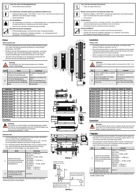
Einbau<br />
Bitte beachten Sie:<br />
Vom <strong>Bremswiderstand</strong> kann eine intensive Wärmestrahlung ausgehen.<br />
Halten Sie deshalb ausreichend Abstand zu benachbarten<br />
Baugruppen, siehe Bild 1.<br />
Montieren Sie den <strong>Bremswiderstand</strong> auf eine geerdete , am besten<br />
chromatierte oder verzinkte Montageplatte. Achten Sie auf einen<br />
möglichst großflächigen Kontakt des Gehäuses mit der Platte.<br />
Beachten Sie bei Montage an der Schaltschrankaußenseite die<br />
Schutzart des <strong>Bremswiderstand</strong>es (IP54/IP65).<br />
Anschluss<br />
Achtung:<br />
Die Oberfläche des <strong>Bremswiderstand</strong>es kann in Betrieb<br />
> 250 °C heiß werden.<br />
Schritt Aktion Anmerkung<br />
1<br />
2<br />
Wählen Sie einen geeigneten Platz für die<br />
Montage des <strong>Bremswiderstand</strong>es.<br />
Reißen Sie die Position der Gewindelöcher<br />
auf der Montageplatte an.<br />
Schneiden Sie für jede Befestigungsschraube<br />
ein Gewinde in die Montageplatte.<br />
Empfohlene Anbaulage siehe<br />
Bild 1.<br />
Maßbilder/Lochabstände siehe<br />
Bild 2.<br />
Über die Gewindefläche erreichen<br />
Sie einen guten flächigen<br />
Kontakt (EMV).<br />
Maße [mm] B (Breite) H (Höhe) T (Tiefe) Abb.<br />
BR-200.01, 540,UR 40 160 26 A1<br />
BR-200.02, 540,UR 80 300 28 A2<br />
BR-200.03, 540,UR 42 320 122 A3<br />
BR-090.01, 540,UR 40 160 26 A1<br />
BR-090.02, 540,UR 80 300 28 A2<br />
BR-090.03, 540,UR 42 320 122 A3<br />
BR-090.10, 650,UR 114 865 105 A4<br />
BR-026.01, 540,UR 40 160 26 A1<br />
BR-026.02, 540,UR 80 300 28 A2<br />
BR-026.03, 540,UR 42 320 122 A3<br />
BR-026.10, 650,UR 114 865 105 A4<br />
Beachten Sie:<br />
Achtung:<br />
Zum Schutz vor Stromschlägen oder Beschädigungen schalten<br />
Sie bitte die Versorgungsspannung Ihres Umrichters/Reglers aus,<br />
bevor Sie den <strong>Bremswiderstand</strong> anschließen.<br />
Kondensatorentladezeit > 10 Min.<br />
Anschlussleitungen müssen geschirmt verlegt werden. Der Schirm<br />
muss an beiden Enden aufgelegt werden.<br />
Die Anschlusslitzen des <strong>Bremswiderstand</strong>es Typ A1, A2 + A3 müssen<br />
mit geerdetem Metallschutzschlauch verlegt werden.<br />
Der Temperaturwächter (Bimetallschalter) muss so angeschlossen<br />
sein, dass bei Überhitzung des <strong>Bremswiderstand</strong>es der angeschlossene<br />
Umrichter/Regler vom Netz getrennt wird.<br />
Schritt Aktion Anmerkung<br />
1<br />
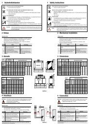
Lesen Sie zuerst die Montageanleitung!<br />
Sicherheitshinweise beachten!<br />
Von elektrischen Antrieben gehen grundsätzlich Gefahren aus:<br />
elektrische Spannungen > 230 V/460 V: Auch 10 min. nach Netz-Aus können noch<br />
gefährlich hohe Spannungen anliegen.<br />
heiße Oberflächen<br />
Ihre Qualifikation:<br />
Zur Vermeidung von Personen- und Sachschäden darf nur qualifiziertes Personal<br />
mit elektrotechnischer Ausbildung an dem Gerät arbeiten.<br />
Kenntnis der nationalen Unfallverhütungsvorschriften<br />
Beachten Sie bei der Installation:<br />
Anschlussbedingungen und technische Daten unbedingt einhalten.<br />
Normen zur elektrischen Installation beachten, z. B. Leitungsquerschnitt,<br />
Schutzleiter- und Erdungsanschluss.<br />
Schließen Sie die beiden<br />
Anschlusskabel des Bremswid.<br />
an die entspr. Klemmen des<br />
Antriebsgerätes an.<br />
SO84.xxx -> X12/RB und L+<br />
(BG1 bis BG4)<br />
SO84.XXX -> X12/ RB+ und RB-<br />
(BG5 bis BG6)<br />
CDE/CDB3000 -> X1/RB und L+<br />
(BG1 bis BG5)<br />
CDE/CDB3000 -> X21/RB+ und RB-<br />
(BG6 bis BG7)<br />
CDD3000 -> X1/RB und L+<br />
CDA3000 -> X1/RB und L+<br />
2<br />
Verbinden Sie den Bimetallschalter<br />
des Bremswid. mit dem<br />
Sicherheitsschaltkreis Ihres<br />
Antriebs.<br />
siehe Bild 3.<br />
Für die Inbetriebnahme lesen Sie bitte das entsprechende Kapitel der zugehörigen<br />
Betriebsanleitung des Umrichters/Reglers.<br />
80.0<br />
58<br />
40<br />
500<br />
1.5<br />
A1<br />
6<br />
32<br />
1000<br />
1000<br />
40<br />
5<br />
18.3<br />
1000<br />
1000 7.5<br />
6<br />
107.5 48<br />
6.2<br />
90<br />
6<br />
60<br />
BR<br />
160<br />
6<br />
A2<br />
865<br />
Regler/ controller<br />
Umrichter/ inverter<br />
A1<br />
45°<br />
300<br />
285<br />
320<br />
310<br />
767<br />
20.0<br />
738.5<br />
30.0<br />
A3<br />
Bild/Fig. 2<br />
UV<br />
6.0<br />
Bimetallschalter/Bimetal switch<br />
Schaltleistung 0,5 A/ 230 V<br />
Maximum load 0.5 A/ 230 V<br />
26<br />
6.2<br />
A2<br />
A4<br />
9<br />
Bild/Fig. 3<br />
A3<br />
9.0<br />
45°<br />
6<br />
34<br />
R6<br />
20.0<br />
5.5<br />
6<br />
11<br />
60<br />
6<br />
8<br />
41.5<br />
Ø 10<br />
6.2<br />
7<br />
115<br />
105<br />
90<br />
80<br />
41<br />
70<br />
18<br />
Not-Aus-Schutzeinrichtung<br />
emergency off protection<br />
First read the mounting instructions!<br />
Follow the safety instructions!<br />
Electric drives present a fundamental safety risk:<br />
Electrical voltages > 230 V/460 V: Dangerously high tension may still be present<br />
even 10 minutes after the power has been cut.<br />
ca. 28.0<br />
75<br />
Hot surfaces<br />
Qualifications:<br />
To avoid personal injury or damage to property, only qualified personnel with training in<br />
electrical engineering may be permitted to work on the device.<br />
Knowledge of national accident prevention regulations.<br />
During installation:<br />
Always observe connection conditions and technical specifications.<br />
A4<br />
Comply with electrical installation standards, e.g. conductor cross-section,<br />
PE conductor and grounding connections.<br />
110<br />
ca.114<br />
Installation<br />
Please note:<br />
• The braking resistor may emit heat intensively, so maintain a safe<br />
distance to adjacent assemblies, see Fig. 1.<br />
Mount the braking resistor on a grounded, preferably chrome-plated<br />
or galvanized backing plate. Make sure that the contact of the housing<br />
with the plate is as broad as possible.<br />
When mounting on the outside of the switch cabinet, observe the<br />
enclosure rating of the braking resistor (IP54/IP65).<br />
Connection<br />
Attention:<br />
The surface of the braking resistor may become hot (>250 °C) in<br />
operation.<br />
Step Action Comment<br />
1<br />
2<br />
Choose a suitable location to install the<br />
braking resistor.<br />
Mark out the positions of the tapped<br />
holes on the backing plate.<br />
Cut a thread in the backing plate for each<br />
fixing screw.<br />
Recommended mounting position<br />
see Fig. 1.<br />
Dimensional drawings/hole spacing<br />
see Fig. 2.<br />
The thread surface provides a<br />
good, wide-area contact (EMC).<br />
Dimensions [mm] W (width) H (height) D (depth) Diagram<br />
BR-200.01, 540,UR 40 160 26 A1<br />
BR-200.02, 540,UR 80 300 28 A2<br />
BR-200.03, 540,UR 42 320 122 A3<br />
BR-090.01, 540,UR 40 160 26 A1<br />
BR-090.02, 540,UR 80 300 28 A2<br />
BR-090.03, 540,UR 42 320 122 A3<br />
BR-090.10, 650,UR 114 865 105 A4<br />
BR-026.01, 540,UR 40 160 26 A1<br />
BR-026.02, 540,UR 80 300 28 A2<br />
BR-026.03, 540,UR 42 320 122 A3<br />
BR-026.10, 650,UR 114 865 105 A4<br />
Please Bild/Fig. note: 1<br />
Attention:<br />
To protect against electric shock or damage, please disconnect the<br />
power from your inverter/controller before connecting the braking<br />
resistor. Capacitor discharge time > 10 min.<br />
Connecting leads must be shielded. The shield must be applied at<br />
both ends. The connecting wires of the braking resistor type A1, A2<br />
+ A3 must be laid with a grounded metal sleeve.<br />
The temperature monitor (bimetal switch) must be connected such<br />
that the power is cut from the connected inverter/controller in the<br />
event of the braking resistor overheating.<br />
Step Action Comment<br />
1<br />
Connect the two connecting<br />
cables of the braking resistor<br />
to the corresponding terminals<br />
of the drive unit.<br />
SO84.xxx -> X12/RB and L+<br />
(BG1 to BG4)<br />
So84.xxx -> X12/RB+ and RB-<br />
(BG5 to BG6)<br />
CDE/CDB3000 -> X1/RB and L+<br />
(BG1 to BG5)<br />
CDE/CDB3000 -> X21/RB+ and RB-<br />
(BG6 to BG7)<br />
CDD3000 -> X1/RB and L+<br />
CDA3000 -> X1/RB and L+<br />
2<br />
Connect the bimetal switch of<br />
the braking resistor to the<br />
safety circuit of your drive.<br />
See Fig. 3.<br />
For commissioning please refer to the relevant section of the accompanying inverter/<br />
controller operation manual.
Für den Fall, dass Ihnen ein Sondermodell<br />
dieses Produktes vorliegt, wenden Sie sich<br />
bitte bzgl. techn. Daten an Ihren Projekteur.<br />
DE<br />
Sicherheitshinweise und Anschlussschema<br />
entnehmen Sie bitte der vorliegenden Montageanleitung.<br />
Technische Daten<br />
Montageanleitung<br />
Bremswiderstände<br />
Bauart<br />
Abbildung Abbildung Abbildung<br />
Technische Daten<br />
A1 A2 A3<br />
Oberflächentemperatur > 250 °C<br />
Berührschutz nein<br />
Spannung max. 970 V DC<br />
Hochspannungsfestigkeit 4000 V DC<br />
Achtung: Bei der Geräteausführung<br />
CXX3x.xxx*, Wx.x, BR und<br />
SO8x.xxx, BR<br />
ist der <strong>Bremswiderstand</strong> integriert. Es darf kein zusätzlicher<br />
<strong>Bremswiderstand</strong> von außen an die Klemmen angeschlossen<br />
werden, das Antriebsgerät würde dadurch beschädigt werden.<br />
*CXX = c-line Drives (CDA, CDD, CDE, CDB ...)<br />
LTi DRiVES GmbH<br />
Internet: www.lt-i.com<br />
E-Mail: info@lt-i.com<br />
Abbildung<br />
A4<br />
Temperaturüberwachung ja, mit Bimetallprotektor (Schaltleistung 0,5 A / 230 V)<br />
Abnahmen CE konform, UL-Recognition<br />
Anschluss 1 m lange PTFE - isolierte Litze<br />
<strong>Bremswiderstand</strong><br />
Bestellbez.<br />
Techn.Daten<br />
Dauerbremsleistung<br />
[W]<br />
Widerstand<br />
[Ω ±10 %]<br />
Spitzenbremsleistung<br />
[W]<br />
bei<br />
390 VDC<br />
bei<br />
750 VDC<br />
Anschlusskasten<br />
mit PG-Verschraubung<br />
Schutzart Abb.<br />
BR-200.01,540,UR 35 200 760 2800 IP54 A1<br />
BR-200.02,540,UR 150 200 760 2800 IP54 A2<br />
BR-200.03,540,UR 300 200 760 2800 IP54 A3<br />
BR-090.01,540,UR 35 90 1690 6250 IP54 A1<br />
BR-090.02,540,UR 150 90 1690 6250 IP54 A2<br />
BR-090.03,540,UR 300 90 1690 6250 IP54 A3<br />
BR-090.10,650,UR 1000 90 1690 6250 IP65 A4<br />
BR-026.01,540,UR 35 26 - 21600 IP54 A1<br />
BR-026.02,540,UR 150 26 - 21600 IP54 A2<br />
BR-026.03,540,UR 300 26 - 21600 IP54 A3<br />
BR-026.10,650,UR 1000 26 - 21600 IP65 A4<br />
Brake <strong>Resistor</strong><br />
Ω Wert<br />
Leistung in [W]<br />
01 = 100 W<br />
10 = 1 kW<br />
Schutzart<br />
Regarding technical data for products in<br />
special execution we kindly ask you to contact<br />
your project engineer.<br />
Bestellschlüssel<br />
BR - . ,<br />
1 = mit Berührschutz<br />
0 = ohne Berührschutz<br />
Brake <strong>Resistor</strong><br />
Ω value<br />
Power in [W]<br />
01 = 100 W<br />
10 = 1 kW<br />
Protection<br />
Type code<br />
BR - . ,<br />
1 = with touch protection<br />
0 = without touch protection<br />
EN<br />
Safety hints and connections are shown in<br />
the installation manual.<br />
Gewerbestraße 5-9 35633 Lahnau<br />
Tel. +49 64 41/9 66-0 Fax +49 64 41/9 66-137<br />
Heinrich-Hertz-Str. 18 59423 Unna<br />
Tel. +49 23 03/7 79-0 Fax +49 23 03/7 79-3 97<br />
Installation Manual<br />
<strong>Braking</strong> <strong>Resistor</strong><br />
Technical data<br />
Design<br />
according according according<br />
Technical data<br />
to A1 to A2 to A3<br />
Surface temperature > 250 °C<br />
Touch protection no<br />
Voltage max. 970 V DC<br />
High-voltage strength 4000 V DC<br />
Attention: In device version<br />
CXX3x.xxx*, Wx.x, BR and<br />
SO8x.xxx, BR<br />
the braking resistor is built-in. No additional braking resistor<br />
may be connected to terminals, otherwise the inverter /servo<br />
controller will be damaged.<br />
*CXX = c-line Drives (CDA, CDD, CDE, CDB ...)<br />
Id.-No.: 0923.00B.1-00 01/2008<br />
according<br />
to A4<br />
Temperature monitoring yes, with Bimetal switch (Maximum load 0,5 A / 230 V)<br />
Acceptance tests CE conpliant, UL-Recognition<br />
Connection 1 m long PTFE insulated litz wire<br />
<strong>Braking</strong> resistor<br />
Order ref.<br />
Tech.data<br />
Cont.<br />
braking<br />
power<br />
[W]<br />
Resistance<br />
[Ω ±10 %]<br />
Peak braking<br />
power [W]<br />
at<br />
390 VDC<br />
at<br />
750 VDC<br />
Connection cabinet<br />
with PG screw<br />
fitings<br />
Protection Diagram<br />
BR-200.01,540,UR 35 200 760 2800 IP54 A1<br />
BR-200.02,540,UR 150 200 760 2800 IP54 A2<br />
BR-200.03,540,UR 300 200 760 2800 IP54 A3<br />
BR-090.01,540,UR 35 90 1690 6250 IP54 A1<br />
BR-090.02,540,UR 150 90 1690 6250 IP54 A2<br />
BR-090.03,540,UR 300 90 1690 6250 IP54 A3<br />
BR-090.10,650,UR 1000 90 1690 6250 IP65 A4<br />
BR-026.01,540,UR 35 26 - 21600 IP54 A1<br />
BR-026.02,540,UR 150 26 - 21600 IP54 A2<br />
BR-026.03,540,UR 300 26 - 21600 IP54 A3<br />
BR-026.10,650,UR 1000 26 - 21600 IP65 A4<br />
Technische Änderungen vorbehalten.<br />
We reserve the right to make technical changes.