ACHTUNG! - Helios Ventilatoren GmbH + Co KG
ACHTUNG! - Helios Ventilatoren GmbH + Co KG
ACHTUNG! - Helios Ventilatoren GmbH + Co KG

Erfolgreiche ePaper selbst erstellen
Machen Sie aus Ihren PDF Publikationen ein blätterbares Flipbook mit unserer einzigartigen Google optimierten e-Paper Software.
Axial-flow Fans AVD.., AVD.. Ex<br />
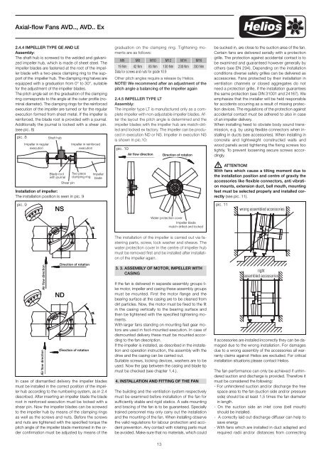
2.4.4 IMPELLER TYPE GE AND LE<br />
Assembly:<br />
The shaft hub is screwed to the welded and galvanized<br />
impeller hub, which is made of sheet steel. The<br />
impeller blades are fastened at the root of the impeller<br />
blade with a two-piece clamping ring to the support<br />
of the impeller hub. The clamping ring halves are<br />
equipped with a graduation from 0° to 30°, suitable<br />
for the adjustment of the impeller blades.<br />
The pitch angle set on the graduation of the clamping<br />
ring corresponds to the angle at the outer profile (nominal<br />
diameter). The clamping rings for the reinforced<br />
execution of the impeller are turned or for the regular<br />
execution formed from sheet metal. If the impeller is<br />
reinforced, the blade root is provided with a journal.<br />
Additionally the journal is locked with a shear pin.<br />
(see pic. 8)<br />
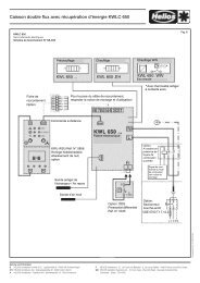
Installation of impeller:<br />
The installation position is seen in pic. 9<br />
.<br />
pic. 8<br />
pic. 9<br />
Impeller in regular<br />
execution<br />
Air flow direction<br />
Air flow direction<br />
Shaft hub<br />
Blade root<br />
with journal<br />
NS<br />
ND<br />
Shear pin<br />
Impeller in reinforced<br />
execution<br />
Two piece<br />
clamping ring<br />
Direction of rotation<br />
Direction of rotation<br />
Impeller<br />
blade<br />
In case of dismantled delivery the impeller blades<br />
must be installed in the correct position of the impeller<br />
hub according to the numbering system, as in 2.4<br />
described. After inserting an impeller blade the blade<br />
root in reinforced execution must be locked with a<br />
shear pin. Now the impeller blades can be screwed<br />
to the impeller hub by means of the clamping rings<br />
as well as the screws and nuts. Before the screws<br />
and nuts are tightened with the specified torque the<br />
pitch angle of the impeller blade mentioned in the order<br />
confirmation must be adjusted by means of the<br />
graduation on the clamping ring. Tightening moments<br />
are as follows:<br />
M6 M8 M10 M12 M14 M16<br />
19 Nm 42 Nm 85 Nm 130 Nm 230 Nm<br />
Data for screws and nuts for grade 10.9<br />
Other pitch angles require a release by <strong>Helios</strong>.<br />
NOTE! We recommend after an adjustment of the<br />
pitch angle a balancing of the impeller again<br />
2.4.5 IMPELLER TYPE LT<br />
Assembly:<br />
The impeller type LT is manufactured only as a complete<br />
impeller with non-adjustable impeller blades. After<br />
the layout the pitch angle is determined and the<br />
impeller blades with the impeller hub are match-drilled<br />
and locked ex factory. The impeller can be produced<br />
in execution ND or NS. Impeller in execution NS<br />
is shown in pic.10:<br />
pic. 10<br />
Air flow direction Direction of rotation<br />
The installation of the impeller is carried out via fastening<br />
parts, screw, lock washer and sheave. The<br />
water protection cover in the centre of impeller hub<br />
must be removed first and be installed after installation<br />
of the impeller again.<br />
3. 3. ASSEMBLY OF MOTOR, IMPELLER WITH<br />
CASING<br />
If the fan is delivered in separate assembly groups like<br />
motor, impeller and casing these assembly groups<br />
must be mounted. First the motor flange and the<br />
bearing surface at the casing are to be cleaned from<br />
dirt particles. Now, the motor must be fixed to the fit<br />
in the casing vertically to the bearing surface and<br />
then be tightened with the specified tightening moments.<br />
With larger fans standing on mounting feet gear motors<br />
are used in foot-mounted execution. In case of<br />
dismounted delivery these must be mounted according<br />
to the fan description.<br />
If the impeller is installed, as described in the installation<br />
and operation instruction, the assembly with the<br />
drive and the casing can be carried out.<br />
Suitable screws, locking devices, washers are to be<br />
used. Now the gap between the casing and blade tip<br />
must be checked (see chapter 1.4.).<br />
4. INSTALLATION AND FITTING OF THE FAN<br />
The building and the ventilation system respectively<br />
must be examined before installation of the fan for<br />
sufficiently stable and rigid statics. A safe mounting<br />
and bracing of the fan is to be guaranteed. Specially<br />
trained personnel may only carry out the installation<br />
and the mounting of the fan. When installing observe<br />
the valid regulations for labour protection and accident<br />
prevention. Any contact with rotating parts must<br />
be avoided. Make sure that no materials, which could<br />
13<br />
330 Nm<br />
Water protection cover<br />
Impeller blade<br />
match-drilled and locked<br />
be sucked in, are close to the suction area of the fan.<br />
Certain fans are delivered serially with a protection<br />
grille. The protection against accidental contact is to<br />
be examined and guaranteed however generally by<br />
others (see EN 294). Depending on the installation<br />
conditions diverse safety grilles can be delivered as<br />
accessories. Fans protected by their installation in<br />
ventilation channels or closed aggregates do not<br />
need a protection grille, if the installation guarantees<br />
the same protection (see DIN 31001 and 24167). We<br />
emphasize that the installer will be held responsible<br />
for accidents occurring as a result of missing protection<br />
devices. The regulations of the protection against<br />
accidental contact must be adhered to also in case<br />
of an impeller delivery.<br />
When installing heed to obviate body sound transmission,<br />
e.g. by using flexible connectors when installing<br />
in ducts (see accessories). When installing in<br />
concrete and lightweight constructed walls and<br />
wood panels avoid tightening the fixing screws too<br />
tightly. To prevent loosening secure screws accordingly.<br />
� ATTENTION!<br />
With fans which cause a tilting moment due to<br />
the installation position and centre of gravity the<br />
accessories like flexible connectors, anti vibration<br />
mounts, extension duct, bell mouth, mounting<br />
feet must be selected properly and installed correctly<br />
(see pic. 11).<br />
pic. 11<br />
wrong assembled accessories<br />
right<br />
assembled accessories<br />
If accessories are installed incorrectly they can be damaged<br />
due to the wrong installation. For damages<br />
due to a wrong assembly of the accessories all warranty<br />
claims against <strong>Helios</strong> are excluded. For critical<br />
installation situations please contact <strong>Helios</strong>.<br />
The fan performance can only be achieved if unhindered<br />
suction and discharge is provided. Therefore it<br />
must be considered the following:<br />
- For unhindered suction and/or discharge the free<br />
space area to the fan (suction side and/or pressure<br />
side) should be at least 1,5 times the fan diameter<br />
in length.<br />
- On the suction side an inlet cone (bell mouth)<br />
should be installed.<br />
- A correctly laid out discharge diffuser can help to<br />
save energy<br />
- With fans which are installed in duct adapted and<br />
required radii and/or distances from connecting