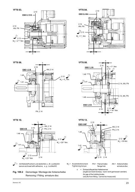
DEUTSCH ENGLISH 3.6.3 <strong>Demontage</strong>/<strong>Montage</strong> der Ankerscheibe 3.6.3 Removing/Fitting armature disc HINWEIS: Die Bremse besteht aus dem feststehenden Magnetkörper (2.10) und der rotierenden Ankerscheibe (AN) mit Flanschnabe (FN) (Baugruppe 2.14). NOTE: The brake consists of a fixed magnet body (2.10) and a rotating armature disc (AN) with flange hub (FN) (assembly 2.14). <strong>Demontage</strong> der Ankerscheibe 1FT6 06. / 1FT6 10. / 1FT613. - Flanschnabe (FN) nicht abziehen, sondern Ankerscheibe (AN) durch lösen der Schrauben (2.12) abschrauben; 1FT6 03. / 1FT6 04. / 1FT6 08. - Gewindestifte (2.13) losdrehen und die Flanschnabe (FN) mit Ankerscheibe (2.14-einteilig) auf ca. 180°C anwärmen und abziehen; Removing armature disc 1FT6 06. / 1FT6 10. / 1FT613. -Do not remove flange hub (FN). Replace armature disc (AN) by removing screws (2.12) 1FT6 03. / 1FT6 04. / 1FT6 08. - Unscrew grub screws (2.13), heat flange hub (FN) and armature disc (2.14, single-piece) to approx. 180°C and pull off <strong>Montage</strong> der Ankerscheibe 1FT6 06. / 1FT6 10. / 1FT613. - mit Schrauben (2.12) neue Ankerscheibe befestigen 1FT6 03. / 1FT6 04. / 1FT6 08. - Flanschnabe mit Ankerscheibe auf max. 160°C erwärmen und auf den Motorläufer aufschrumpfen, wobei die Flanschnabe an der Wellenschulter anliegen muß. Gewindestifte (2.13) mit Loctite 243 oder einem gleichwertigen Klebstoff bestreichen, einschrauben und mit dem angegebenen Drehmoment anziehen 1FT6 03. ... 1FT6 13. - zum Erreichen der vorgeschiebenen Prüfmomente (s. Fig. 109.1) ist die geschlossene Bremse durch langsames Drehen des Motorläufers einzuschleifen - Vor Wiederinbetriebnahme der Bremse sind die Öffnungs-, Wiedereinfall- und Einfallspannung (s. Fig. 109.1) zu prüfen; Fitting armature disc 1F6 06. / 1F6 10. / 1F6 13. - Fix new armature disc with screw (2.12) 1FT6 03. / 1FT6 04. / 1FT6 08. - flange hub with heat armature disc to max. 160°C, shrink-fit onto shaft so that flange hub butts against shoulder of shaft. Apply Loctite 243 or equivalent to grub screws, screw in and tighten to the specified torque 1FT6 03. ... 1FT6 13. - To attain the specified test torque (Fig. 109.1), the applied brake must be ground in by slowly rotating the motor. - Before putting the brake into operation again, check the release, reapplication and application voltages (Fig. 109.1). Typ Type Bremsenbezeichnung Brake designation Prüfmoment Test torque ≥ .. [ Nm ] Öffnungsspannung Releasing voltage ≤ .. [ V ] Wiedereinfallspannung Re-application voltage ≥ .. [ V ] Einfallspannung Application voltage ≥ .. [ V ] 1FT6 03. EBD 0,15 B 2,8 18 26,4 5 1FT6 04. EBD 0,4 B 7,2 20 26,4 8 1FT6 06. EBD 1,5 B 28 20 26,4 6,5 1FT6 081/082 EBD 1,2 B 17 20 26,4 7,5 1FT6 084/086 EBD 3,5 B 44 20 26,4 8,5 1FT6 10. EBD 4 M 118 21,6 26,4 6 1FT6 13. EBD 8 MF 225 21,6 26,4 6 gemessen bei Raumtemperatur von ca. 20 °C und sich ergebendem Einbauluftspalt measured at room temperature (about 20 °C) and with the resulting air gap Fig. 109.1 Prüfmomente der Bremse Brake test torques 22 Siemens AG
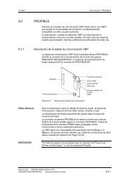
1FT6 03. EBD 0,15 B 2.10 1FT6 04. EBD 0,4 BA 2.10 2.14 AN, FN 2.14 AN, FN 2.13 M A = 7 -1 Nm 2.13 M A = 2 +0,5 Nm s s 1FT6 06. s 1FT6 08. s EBD 1,5 B 2.10 AN, 2.14 EBD 1,2 B 2.10 M A = 7 +1 Nm 2.13 1.48 2.12 1.48 M A = 5 -1 Nm 1.41 1.41 2.14, AN, FN 1.48 2.14, AN, FN EBD 3,5 B FN, 2.14 2.10 2.13 M A = 18 +2 Nm s 1FT6 10. 1.48 EBD 4 B 2.10 s AN, 2.14 FN, 2.14 1FT6 13. EBD 8 MF 1.48 2.10 s AN, 2.14 FN, 2.14 1.41 2.12 M A = 20 +2 Nm 1.41 2.12 M A = 35 Nm 2.13 M A = 23 +2 Nm 2.14 2.15 2.14 = mit Klebstoff sichern und abdichten, z .B. Loctite243 secure and seal with adhesive, e. g. Loctite243 M A = Anziehdrehmoment Tightening torque FN = Flanschnabe flange hub AN = Ankerscheibe armature disc Fig. 109.2 <strong>Demontage</strong> / <strong>Montage</strong> der Ankerscheibe Removing / Fitting armature disc s = Einbauluftspalt der Haltebremse (ergibt sich beim Einbau - kann nicht gemessen werden) Air gap of the holding brake (results from fitting - cannot be measured) Siemens AG 23