The LANL Edition BEAM ScoutWalker 2.2 Walking Robot© The ...
The LANL Edition BEAM ScoutWalker 2.2 Walking Robot© The ...
The LANL Edition BEAM ScoutWalker 2.2 Walking Robot© The ...

You also want an ePaper? Increase the reach of your titles
YUMPU automatically turns print PDFs into web optimized ePapers that Google loves.
S COUTW ALKER 2 .2 - P ARTS L IST1 - SW<strong>2.2</strong> Printed circuit board4 - Walker leg mounting pads2 - 47cm (18.5”) Heavy-gauge leg wire (cut each 25.5cm from one end to make 4 legs)6 - 74AC240 Octal buffer chips1 - 8cm (3.15”) Length of 1/4” Heat-Shrink Foot Sleeve (cut into four 2cm lengths)4 - Servos and servo accessory pack1 - 12” Length of servo wire4 - ‘AA' batteries2 - Dual ‘AA' battery holders1 - Power switch4 - Large zip ties8 - Small zip ties8 - Part ‘C1’ = Capacitor 0.1µF monolithic - Master Oscillator6 - Part ‘C2’ = Capacitor 22µF electrolytic - Power Decoupling2 - Part ‘C3’ = Capacitor 6.8µF electrolytic - Reverse Timer10 - Part ‘R1’ = Resistor 470 ohm (Yellow / Purple / Brown) - LED Current Limiters4 - Part ‘R2’ = Resistor 47k (Yellow / Purple / Orange) - Reverser Bypass & Enable Pull-downs2 - Part ‘R4’ = Resistor 1.0M (Brown / Black / Green) - Reverse Time2 - Part ‘R5’ = Resistor 3.6M (Orange / Blue / Green) - Master Oscillators2 - Part ‘R6’ = Resistor 1.3M (Brown / Orange / Green) - Slaves2 - Part ‘R7’ = Same as above (1.3M)1 - Part ‘R8’ = Resistor 1.0M (Brown / Black / Green) - ‘Corpus Callosum’ Link18 - Socket pins for Resistor Mounting8 - Yellow Miniature LEDs (Motor activation indicators)2 - Green Miniature LEDs (Tactile sensor indicators)12 - #2-1/4 sheet metal screws (Leg pad mounting screws)2 - Sets of tactile sensors (2-Pins, 1-Length 1/16” Heat Shrink, 2-Sensor Springs)Not included, but referred to on the Printed Circuit Board:3* - Part ‘D1’ . = Diode 1N914 signal - Head Kit interface2* - Part ‘R3’ = Resistor 1k (Brown / Black / Red) - Opt. Reverser Inputs2* - Part ‘R9’ = Resistor 1M (Brown / Black / Green) - Optional Tactile Sensor Delay2* - Part ‘R10’ = Resistor 100 Ohm (Brown / Black / Brown) - Head kit delay2* - Part ‘R11’ = Resistor 1k (Brown / Black / Red) - Head kit interface enable override2* - Part ‘R12’ = Resistor 240k (Red / Yellow / Orange) - Head limit gate back-offWe strongly suggest you inventory the parts in your kit to make sure you have all the parts listed. If anything is missing,contact Solarbotics Ltd. For replacement parts information.Disclaimer of LiabilitySolarbotics Ltd. Is not responsible for any special, incidental, or consequential damages resulting from any breach ofwarranty, or under any legal theory, including lost profits, downtime, good-will, damage to or replacement of equipmentor property, and any costs or recovering of any material or goods associated with the assembly or use of this product.Solarbotics Ltd reserves the right to make substitutions and changes to this product without prior notice.
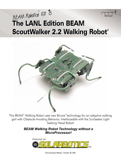
S COUTW ALKER 2 .2 - INTRODUCTION<strong>The</strong> <strong>ScoutWalker</strong> 2 is a new style of walking robot that utilizes a very non-digital approach; Bicoretechnology. Unlike traditional microprocessor or even <strong>BEAM</strong> “Nervous Net” technology, Bicore walkers usecontinuous phase differences between legs to achieve very interesting and unique walking behaviors.Another interesting property of this robot is the multi-purpose use of a logic buffer chip in ways it was neverdesigned to be used. <strong>The</strong> 74AC240 is designed to buffer data communications in two directions, but Mr.Mark Tilden (the inventor of <strong>BEAM</strong> Robotics) utilizes it so it acts as a motor driver; multiplexor (formodifying the walking gait); sensor input conditioner; and phasing oscillators. This lets the <strong>ScoutWalker</strong> 2achieve all its functions by using the same chip in 6 places.When finished, the <strong>ScoutWalker</strong> 2 will be able to walk forward, reverse, and turn on the spot in eitherdirection based on sensory inputs. It also has facility to be adapted to other controlling devices, allowing theinterface of the <strong>ScoutWalker</strong> 2 with microprocessor “brains” that tell it which way to go, or even to theSunSeeker Head Light-Seeker so that it can track sources of light. In its stock configuration, the <strong>ScoutWalker</strong>2 comes with a pair of tactile (touch) sensors and a “raw” multiconfigurable bicore section to interface othersystems with the <strong>ScoutWalker</strong> 2. <strong>The</strong>re are also the necessary accommodations made to interface theSunSeeker Head kit to the <strong>ScoutWalker</strong> so it has an active light-seeking head.<strong>The</strong> kit comes with all that is necessary to construct a fully functional walking robot, but we suggest you usethe included socket pins to play with the values of the resistors that set the phase variances. This will let youexplore what Bicore technology can do, and how robust it can be.<strong>The</strong> walking gait is set by the two front Bicores, which oscillate independently, but are loosely linked by a“Corpus Callosum” resistor that makes them gently influence each other. This establishes a left/rightcoordination. Each of these front “master” Bicores are linked to a “slave” Bicore that controls each of therear legs. By selecting appropriate resistor values to link the “masters” to the “slaves”, the phasing is set thatresults in a walking gait.Making the <strong>ScoutWalker</strong> 2 backup and turn is accompished by the “IMx” Bicore in the lower center of thePCB. This Bicore acts as a multiplexor, and when activated (by the touch sensors or additional circuitry),swaps around the phase resistor connections so the phase difference encourages a reverse walking gait ratherthan a forward one. A built-in timer governs when the reverse gait times out, and sets the phase angle backto the original configuration.Required Tools to complete this kit:Soldering IronX-Acto Knife or razor bladeSnipsPliersPhillips-head screwdriverLighter or Match(1)
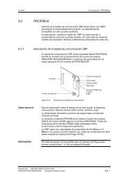
74AC240S COUTW ALKER 2 .2 - E LECTRONICS A SSEMBLY<strong>The</strong> <strong>ScoutWalker</strong> 2 is pretty straightforward to assemble. Follow the instructions step by step, checking off eachbox as you progress. This will guarantee that everything gets done in the order needed, and that you don’taccidently mount the multi-phasic shield generators in backwards. (And I’m sure we all know how embarrassingthat can be!)Snap off tabsLeg mounting Pads1Start by separating the leg mounting pads fromthe main printed circuit board (the ‘PCB’).Although not necessary, sand or file the little tabsoff each part after snapping them off.2Start with the most important (and fun) part to install -the 74AC240. Install it in the 6 positions labeled74AC240 as shown, with the notch at the top of thechip pointing upwards! Carefully solder them in place.(2)
S COUTW ALKER 2 .2 - E LECTRONICS A SSEMBLYStep 40.1µFCommon tothe 4 cornerchipsStep 322µFStep 56 x 22µF2 x 0.1µF2 x 470 ohmStep 32 x 470 Ohm3Install the 10 current limiting 470 ohm resistors for theindicator LEDs in positions labeled ‘R1’.4Install the 8 - 0.1µF (labeled ‘104’) monolithic oscillatorcapacitors on each of the 4 corner 74AC240 chips in thepositions labeled ‘C1’. <strong>The</strong>se parts are NOT polarity sensitive..Note that there are 3 holes in each area indicated for the cap.Two of the holes are joined by a trace to facilitate easierinstallation of the caps for different pin spacing. Make sure thecapacitor is only installed using one of these two joined holes.MAKE SURE THEY LAY FLAT against the PCB!5Install the 6 - 22µF decoupling (power-smoothing) capacitorsfor the 74AC240 chips in the positions labeled as little circleswith the ‘+’ sign. <strong>The</strong>se caps are polarity sensitive, so makesure they go in with the side with the strip away from the‘+’ sign. Install them with the leads bent over 90 degrees sothey lay flat against the PCB.6Install the 47k resistors (R2) in the positionslabeled ‘47k’. This turns on all the ‘240 chips bydefault7Install the 2 - 6.8µF capacitors in thepositions labeled ‘C3’. <strong>The</strong>se capacitorsARE polarity sensitive, so make sure theleg labeled with the little ‘+’ goes to theright pad! FOLD THE CAP FLATAGAINST THE PCB.Step 647kStep 72 x 6.8µF6.8µF(3)Step 64 x 47k
S COUTW ALKER 2 .2 - B ATTERY H OLDERS AND W IRING11Install the battery holders as shown, with the wires facingtoward the middle. Use the mounting screws from the servoaccessory pack to screw the holders in. Grind or snip off thepointy portion that sticks through the other side of the PCB.12Wire up each battery holder so the red and black wiresgo to one of the two battery connection terminals. Red is‘+’, black is ‘-’.(5)
S COUTW ALKER 2 .2 - S ERVO M ODIFICATIONS<strong>The</strong> servos are obviously the business end of the walker. Unfortunately for the servos, you'll be performing alittle "open-heart" surgery on them (insert maniacal laughter here). Why? Well, to be honest, we simplycannot find gearmotors near as strong and inexpensive as modified servos, but their internal electronicssimply aren't compatible with the Bicore controller. So fish out your Phillips head screwdriver, the length ofpaired wire, and the servos - we're going to go hacking!13Start by removing the bottom plate from the servo, andbe careful not to lose the screws (sorry to sound likeyour mom, but these are dang-near impossible toreplace).14Gently pry the servos electronic guts out with aelectronic-guts puller tool (if that's not handy, use ascrewdriver). <strong>The</strong> PCB is connected to the servomotor and feedback pot, so expect to see these as youpull the whole assembly out.Desolder here15Remove the motor from the PCB by desoldering it fromthe solder mounting pads indicated. As for the leftoverPCB and pot, you can feed it to your cat or dog, but notyour hampster - that would be silly...16Gently push the motor back into place. <strong>The</strong>n solder thefull length of the red/black wire onto the motor, with thered wire attached to the motor pole closest to the reddot. After you put the bottom plate back on, measure 2"from where the wire leaves the servo, and clip off theextra wire.Repeat the whole thing over again on the other threeservos.(6)
S COUTW ALKER 2 .2 - S ERVOS17<strong>The</strong> PCB is essentially finished at this point. No more electronics; mechanics instead! Grab the 4 modified servos and install them asshown, going between the large holes, and secure with the zipties. Use the small zipties to secure the servo to the PCB at the holesnear the edge, and the large one to secure the servo across the chip underneath. Pay special attention to how the large ziptiesare mounted across the rear (bottom) servos - this is very important for later use!Make sure the servos are oriented so the servo wires face forwards for the front servos; rearwards for rear servos.When you’re finished with the zipties, solder the red wire to the motor connection pad labeled ‘+’, and the black wire to the otherpad.BlackRedWrap the large ziptie so that it goes through theclasp on the other side of the board (where theLEDs are), with the extra exiting directly out theback.Note ziptie positioning.Do NOT clip the ends off!(7)
S COUTW ALKER 2 .2 - R ESISTOR INSTALLATION18Now it is time to install the biasing resistors that will make your <strong>ScoutWalker</strong> develop the rhythms that will makeit successfully walk. Install the resistors in the positions shown, and you will have a good baseline for your<strong>ScoutWalker</strong>. We encourage you to experiment with the phase relationships - that’s why you have the jumper pinsockets installed.R6&R7Slave Resistors R5 - ‘Master Bias Left’R8 - ‘CC Res’R5 - ‘Master Bias Right’R4 - Reverse Time<strong>The</strong> ‘CC’ resistor governs howstrong the left and right front motorsinfluence each other. Strong slaving (small R)reduces natural adaption, while weakslaving results in more chaotic walking gaits<strong>The</strong> signals propagate from thefront motor bicores to the rearmotor bicores through theseresistors. You can adjust howlong the rear motors delay fromthe front motors by changingthese resistor values.Now if you’re confident that everything is in place, plug in only 3 of the batteries. If you have an accidentalshort on the robot, you can burn up the batteries and/or damage the circuit board, so the fourth battery hasto be installed quickly and be ready to pull it out quickly if you feel the batteries getting warm, or see/smellsmoke! If nothing happens, flip the switch, and watch the motors move in sync to the blinky lights!(8)
Resistorclippings70 mm(2-7/8”)35 mm(1-3/8”)20 mm(3/4”)Resistorclippings42mm(1-5/8”)60mm(2-3/8”)Front RIGHT LegS COUTW ALKER 2 .2 - L EG S HAPES50mm(2”)Rear LEFT LegRear RIGHT Leg10 mm(3/8”)30mm(1-3/16”)Front LEFT Leg(9)19<strong>The</strong> Rear Legs - Fold one of the thick leg wires intothe shape in the diagram, being as accurate as youcan reasonably be.Where you see the triangular plate in relation to thewire, strip off the insulating coating and secure thewire to the mounting pad with resistor clippings.Solder the leg wire to the pad.Repeat the process for the other leg, but REVERSEthe fold direction of the 50mm length, and solder it tothe other side of the plate, so you have one rear leg,and a mirror image.Take the servo “X” horn off two servos, and screwthe leg assemblies to each horn with the #2-1/4”sheet-metal screws. Don’t re-attach the assembly tothe servos - they have to be aligned up to the servoon the frame (later).20<strong>The</strong> Front Legs - Fold one of the thick leg wiresinto the shape in the diagram, being as accurate asyou can reasonably be.Fold one as closely to the diagram as possible. Youwill note that we haven’t given you exact dimensionsfor the front part of the leg. Well, that’s because theydon’t matter. <strong>The</strong> only thing that does really matter iswhere the front “foot” is in relation to the pivot pointon the servo. So use whatever shape you want forthe front of the leg, but try to get the tip to touch theground as close as possible to the dimensions given.Where you see the triangular plate in relation to thewire, strip off the insulating coating and secure thewire to the mounting pad with resistor clippings.Solder the leg wire to the pad.Repeat the process for the other leg, but REVERSEthe fold direction of the 30mm length, and solder it tothe other side of the plate, so you have one leg, anda mirror image..Take the servo “X” horn off two servos, and screwthe leg assemblies to each horn with the #2-1/4”sheet-metal screws. Don’t re-attach the assembly tothe servos - like the front legs, they have to bealigned to the servos while on the main walker body.1cm 2 3 4 5 6 7 8 9 10 11 12 13 14 15 16 17 18 19 20 21 22 23 24 25 26
S COUTW ALKER 2 .2 - L EG INSTALLATION / S ENSORSForwardServo rotatedfully counterclockwiseServo rotatedfully clockwise21When putting the servo horn / leg assembly onto the servo, youmust rotate the servo until it hits the internal stop inside theservo. <strong>The</strong>n slide the servo horn onto the splined shaft so itlooks like the leg positions in the picture. Screw the servo hornretaining screw back in. If you want, clip off the 4th unusedservo arm, so it’s not poking down where it can catch on otherobstacles. It’s a good idea, but not absolutely necessary.Rear leg stopFront leg stop22When you rotate the servos the other direction, the leg shapesshould make them stop at the points shown. <strong>The</strong> front legs willhave their stop hit the top of the PCB, and the rear legs willhave their stop hit the bottom of the ziptie you used to securethe rear servos.When you finish mounting the legs, heat-shrink on the littleblack tube feet onto the end of each leg tip, using a flame. Don’tburn them - flames and smoke are bad! Tip: Try using differentmaterials for “booties” for better traction, like replacement eraser nubs for pencils.Now that your legs are installed, you can turn on your robot, and place it on a surface to see whatit will do. Don’t despair if it doesn’t walk super-fantastic the first time - the leg shapes most likelywill need tweaking before it’s fully optimized. Ideally, the <strong>ScoutWalker</strong> will lift a front leg off theground, then be pushed forward back onto the ground by the rear leg. You want the legs to eachbe lifted off the ground in their own turn so it can more easily step over obstacles. Leg designoptimization is going to be the hardest task you will face in the construction of this kit, but it is alsothe most fun!23 <strong>The</strong>re's not too much rocket (or robot....) science here. Simply put, we're building a sensor thatactivates each ½ reverse circuit when bumped from any direction. When the spring deflectsenough to contact the brass rod in the center of the spring, the circuit activates.Heat-Shrink TubingBrass RodBrass RodLeave 8mm (1/4”) out toattach to long sensor mounting padContact to be soldered toforward mounting padSensor SpringTo Reverse ProbeShrink a 1cm (3/8") length of tubing onto the end of the rod, leavingabout 8mm (1/4) free on the end Ummm.... That’s about it until weget to the next stage where we solder the assembly to the robotboard.(10)
S COUTW ALKER 2 .2 - INSTALLING T ACTILE S ENSORS26Assuming that your <strong>ScoutWalker</strong> 2 is functioning properly, now is thetime to add the sensors to your robot. Lay out your sensor as shown,soldering the brass pin the innermost pads, and the wire leg to theoutermostYou may find it easier to secure the brass pin to the board with aleftover resistor clipping, by tying it to the board before you solder. <strong>The</strong>close-up image shows what you can expect to see after you solder suchan installation into place.If you find that your sensor is a bit too sensitive, you can implement thesolution below - shrink some heat-shrink tubing to the outside of thesensor spring. This will dampen (or lessen) the vibrations that mayaccidently trigger them.(11)
S COUTW ALKER 2 .2 - W HERE TO G O FROM H ERE?Now you’re free to throw the switch and let your <strong>ScoutWalker</strong> <strong>2.2</strong> go bouncing around the room.We’ve had great fun with this. Assuming your tactile sensors are arranged so they protect the fullfront of the robot, it shouldn’t get held up by any desk/chair leg, box, bag, or dog that it happensacross.After you’re worn out a set of batteriesor two doing this, you may beready for more excitement. <strong>The</strong> firstobvious modification is to add aSolarbotics SunSeeker head to yourrobot. This conjoining of a lightseekingrobot ‘rider’ on a walkingrobot ‘horse’ makes for interestingwatching!<strong>The</strong> <strong>ScoutWalker</strong> II quite easilyhandles the extra load of theSunSeeker (shown without it’sSolarcell). In fact, we’ve witnessed anincrease in performance, as the legswere better loaded by the increasedweight of the SunSeeker.<strong>ScoutWalker</strong> II interfaced with the SunSeeker Head<strong>The</strong> SunSeeker isn’t the only modification available to you with the <strong>ScoutWalker</strong> II. As part of thecontrol circuitry for the head/body interface, there are 6 left-over unused gates on the front middle74AC240 which you may use in any way you wish. You will notice that the inputs to the unusedgate are connected by a very thin trace to Vcc ( always tie unused inputs high or low for lowerpower consumption). Simply scratch these traces off if you wish to use these inputs.Additional to these unused gates, there is a whole breadboarding area in the middle of the walker.Designed to accommodate a 20 pin DIP IC (ie: a 74AC240/245), you’ll find power and ground linesnear the appropriate points, and lots of extra pads available for custom electronics. Add your ownactive IR ranging; night-time “head-lights”; microcontroller (ie:PIC/Basic Stamp) interfaces; Solar charge-pumping nicadrechargers; electronic compass / GPS interface; RF dataInterface; or even just a blinky light for the heck of it!Have fun with your <strong>ScoutWalker</strong> II, and let us know whatyou’ve been able to do with it!Extra unused 74AC240 gatesSpare bread-boarding space(12)
S COUTW ALKER 2 .2 - F UNCTIONAL S CHEMATIC & C LOSING W ORDSOmitted from this schematic is the 74AC240 in the front middle of the circuit board. This chip is used for userdesignedexperiments and for interfacing the SunSeeker Head Robot to the <strong>ScoutWalker</strong> II.PowerMaster BicoreOscillators & FrontMotor DriversTactile-activatedMultiplexorIC1 - 74AC240Slave BicoreOscillators & RearMotor DriversVccIC1 - 74AC240VccIC1 - 74AC240R1C3R2R4R1R6C1R5C1MR2R7C1C1MR1R1R1R8IC1 - 74AC240R1C3VccR4R1R2C1R5C1MR2R7R6C1C1MR1R1R1We hope you have as much fun assembling and playing, ummm, experimenting with your <strong>ScoutWalker</strong> II as we did. We spentconsiderable time getting this design right, and we hope it shows in the performance of your robot. If you have any questionsregarding this kit, please contact us!Solarbotics Ltd.179 Harvest Glen Way N.E.Calgary, Alberta, Canada T3K 4J4Ph: (403) 818-3374 / (403) 226-3793 Fax: (403) 226-3741Website: http://www.solarbotics.comEmail: info@solarbotics.com© Copyright Solarbotics Ltd., 2000(13)