AU - Absauganlage stationär KEMPER Truck-/ Car extraction ...
AU - Absauganlage stationär KEMPER Truck-/ Car extraction ...
AU - Absauganlage stationär KEMPER Truck-/ Car extraction ...

Sie wollen auch ein ePaper? Erhöhen Sie die Reichweite Ihrer Titel.
YUMPU macht aus Druck-PDFs automatisch weboptimierte ePaper, die Google liebt.
Art.-Nr. 150 0087 Stand: 04/2011<br />
<strong>KEMPER</strong><br />
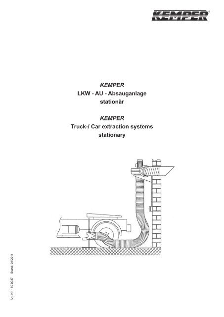
LKW - <strong>AU</strong> - <strong>Absauganlage</strong><br />
<strong>stationär</strong><br />
<strong>KEMPER</strong><br />
<strong>Truck</strong>-/ <strong>Car</strong> <strong>extraction</strong> systems<br />
stationary
Deutsch ........................................................................................................................... 2<br />
English ............................................................................................................................. 4<br />
1
Verwendung und Wirkungsweise<br />
Das <strong>KEMPER</strong> LKW – <strong>AU</strong> Absaugset wurde speziell für die Absaugung der Abgase bei der LKW - Abgasuntersuchung entwickelt.<br />
Hierfür ist es mit einem öl- und temperaturbeständigen Abgasschlauch und einem in Höhe und Neigung verstellbaren<br />
Abgasstandtrichter ausgerüstet. Der auf einer Wandkonsole schwingungsdämpfend montierte Silumingussventilator saugt die<br />
Abgase / Nebenluft an und fördert diese über das Abluftset in den Außenbereich.<br />
Sicherheitshinweise<br />
Achtung:<br />
Beim Gebrauch von Elektrogeräten sind zum Schutz gegen elektrischen Schlag, Verletzungs- und Brandgefahr folgende<br />
grundsätzliche Sicherheitsmaßnahmen zu beachten!<br />
Lesen und beachten Sie diese Hinweise, bevor Sie das Gerät benutzen:<br />
• Bewahren Sie diese Montage- und Betriebsanleitung gut zugänglich auf.<br />
• Setzen Sie das Gerät nicht zur Absaugung von leicht entzündlichen / explosiven bzw. aggressiven Medien ein.<br />
• Verwenden Sie nur Original – Ersatzteile.<br />
• Lassen Sie das Gerät nur von einem authorisierten Elektriker anschließen.<br />
• Schützen Sie das Gerät vor Nässe und Feuchtigkeit.<br />
• Schützen Sie das Kabel vor Hitze, Öl und scharfen Kanten.<br />
Montage<br />
• Befestigen Sie die Wandkonsole mit den beiliegenden Befestigungsteilen in einer Höhe von ca. 2 m an einer tragfähigen<br />
Wand.<br />
• Tauschen Sie nun die 4 der 8 M6-Schrauben, mit denen der saugseitige Ventilatordeckel auf dem Ventilatorgehäsuse befestigt<br />
ist, durch die beiliegenden Gummi-Metall-Elemente.<br />
• Legen Sie nun den Ventilator (siehe Abbildung) auf die Wandkonsole und befestigen ihn mit Fächerscheiben und M6 –Muttern.<br />
• Stecken Sie die Reduzierung Ø 250 mm/200 mm in den Ansaugstutzen des Ventilators und befestigen Sie sie mit den<br />
beiliegenden Schrauben.<br />
• Schieben Sie den Abgasschlauch mit der Schlauchschelle auf den Stutzen Ø 200 mm und befestigen Sie ihn.<br />
• Schrauben Sie das Übergangsstück aus Alu-Guss an den Ausblasstutzen des Ventilators.<br />
• Nun können Sie den Flanch und den Stutzen für den Anschluss der Abluftleitung montieren.<br />
• Befestigen Sie an diesem Stutzen die flexible Aluminium-Abluftleitung und den Ausblasstutzen mit Vogelschutzgitter jeweils<br />
mittels einer Schlauchschelle und führen Sie den Ausblasstutzen durch ein entsprechendes Loch in der Außenwand nach<br />
draußen.<br />
• Den Abgasstandtrichter und den Saugstutzen des Ventilators verbinden Sie ebenfalls mit dem Abgasschlauch mittels der<br />
beliegenden Schlauchschellen<br />
• Montieren Sie den Motorschutzschalterin der gewünschten Bedienhöhe an der Wand und lassen Sie ihn und den Ventilator<br />
von einem authorisierten Elektriker an Ihr Stromnetz anschließen. Beachten Sie hierbei die Angaben auf dem Typenschild und<br />
die Drehrichtung des Ventilators!<br />
2<br />
Deutsch
Explosionszeichnung<br />
Ersatzteil-Liste<br />
Pos. Bezeichnung Artikel-Nr.<br />
1 Abgasstandtrichter, komplett 96 160 200 03<br />
2 Abgasschlauch Ø 200 mm, 6 m 114 0152<br />
3 Wandkonsole, inkl. Schwingungsdämpfer 96 160 200 02<br />
4 Silumingussventilator 3.000 m³/h, 3 x 400 V / 50 Hz 92 215 103<br />
5 Motorschutzschalter, komplett mit Gehäuse 94 170 102<br />
6 Abluftset mit Ausblasstutzen 96 160 201<br />
3
Application and operation<br />
The <strong>KEMPER</strong> <strong>Truck</strong>-/ <strong>Car</strong> <strong>extraction</strong> set is used to extract exhaust gases during the truck emission test. The unit is equipped<br />
with an oil and temperature resistant exhaust hose as well as with an exhaust funnel, which is adjustable in height and inclination.<br />
The cast silumin fan, which is vibration isolated mounted on a wall bracket, extracts exhaust gases and secondary air and<br />
leads it outside by means of the extracted air set.<br />
Safety Instructions<br />
Caution:<br />
When using electrical devices, the following basic safety instructions must be followed in order to prevent shock, injury or fire!<br />
Read and follow these instructions before using the filter unit!<br />
• Keep this installation and operating manual near the filter unit.<br />
• Do not use the unit to extract easily flammable, explosive or aggressive substances.<br />
• Only use original spare parts.<br />
• Installation and start-up of components should only be carried out by an authorised electrician.<br />
• Protect the unit from dampness and wetness.<br />
• Protect the electrical cable from heat, oil and sharp edges.<br />
Installation<br />
• Connect the wall bracket with the provided connection material at a height of ca. 2 m to a stable wall.<br />
• Please exchange 4 of the 8 M6 bolts, which connect the fan lid on the <strong>extraction</strong> side to the fan housing, with the provided<br />
rubber metal elements.<br />
• Now please put the fan (see illustration) on top of the wall bracket and fasten it with the serrated washers and M6 nuts.<br />
• Push the reducer Ø 250 mm/ 200 mm into the blow out piece of the fan and fasten it with the provided bolts.<br />
• Push the exhaust hose with the hose clamp over the blow out piece Ø 200 mm and fasten it.<br />
• Screw the aluminium casted adaptor to the blow out piece of the fan.<br />
• Now you can mount the flange and the blow out piece for the connection of the exhaust pipe.<br />
• Connect to this blow out piece the flexible aluminium exhaust pipe and the blow out piece with bird protection grid by means of<br />
a hose clamp. Guide the blow out piece through a corresponding hole in the exterior wall outside.<br />
• Connect the exhaust funnel and the blow out piece of the fan to the exhaust hose by means of the provided hose clamps.<br />
• Connect the motor protection switch at a desired height to the wall and have it as well as the fan connected to the power<br />
supply by an authorised electrician. Please note the information on the type lable and the rotation direction of the fan!<br />
4<br />
English
Exploded drawing<br />
Spare parts list<br />
Pos. Description Part no.<br />
1 Exhaust funnel, complete 96 160 200 03<br />
2 Exhaust hose Ø 200, 6 m 114 0152<br />
3 Wall bracket, incl. vibration absorber 96 160 200 02<br />
4 Silumin fan 3.000 m³/h, 3 x 400 V / 50 Hz 92 215 103<br />
5 Motor protection switch, complete with housing 94 170 102<br />
6 Extraction set with blow out piece 96 160 201<br />
5
Deutschland<br />
<strong>KEMPER</strong> GmbH<br />
Von-Siemens-Str. 20<br />
D-48691 Vreden<br />
Tel. +49(0)2564/68-0<br />
Fax +49(0)2564/68-120<br />
mail@kemper.eu<br />
www.kemper.eu<br />
United Kingdom<br />
<strong>KEMPER</strong> (U.K.) Ltd.<br />
Venture Court<br />
2 Debdale Road<br />
Wellingborough Northamptonshire<br />
NN8 5AA<br />
Tel. +44(0)1327/872909<br />
Fax +44(0)1327/872181<br />
mail@kemper.co.uk<br />
www.kemper.co.uk<br />
España<br />
<strong>KEMPER</strong> IBÉRICA, S.L.<br />
Av. Riera Principal, 8<br />
E-08328 Allela/Barcelona<br />
Tel. +34 902 109 454<br />
Fax +34 902 109 456<br />
mail@kemper.es<br />
www.kemper.es<br />
China<br />
<strong>KEMPER</strong> Exhaust System<br />
(Shanghai) Co. Ltd.<br />
No. 14 Building, Xiao-Nan Road<br />
Jianghai Industry Area<br />
FengXian District<br />
Shanghai 201400<br />
P.R. of China<br />
Tel. +86(21)33658991<br />
Fax +86(21)37441682<br />
France<br />
<strong>KEMPER</strong> sàrl<br />
ZI du Ried<br />
3 Impasse Hutmatt<br />
F-67590 Schweighouse sur Moder<br />
Tel. +33(0)388072980<br />
Fax +33(0)388072010<br />
mail@kemper.fr<br />
www.kemper.fr<br />
Nederland<br />
<strong>KEMPER</strong> B.V.<br />
Postbus 83<br />
NL-7140 AB Groenlo<br />
Verkoopkantoor<br />
Tel. +49(0)2564/68-137<br />
Fax +49(0)2564/68-120<br />
mail@kemper-bv.nl<br />
www.kemper-bv.nl<br />
Česká Republika<br />
<strong>KEMPER</strong> spol. s r.o.<br />
Pyšelská 393<br />
CZ-257 21 Poříčí nad Sázavou<br />
Tel. +420/317 798 000<br />
Fax +420/317 798 888<br />
mail@kemper.cz<br />
www.kemper.cz<br />
United States<br />
<strong>KEMPER</strong> America, Inc.<br />
5910 Shiloh Road East<br />
Suite 110<br />
Alpharetta, GA 30005<br />
Tel. 770/4167070<br />
Fax 770/8280643<br />
mail@kemperamerica.com<br />
www.kemperamerica.com<br />
1-800-756-5367