NANOPERM® Cool BLUE®-Kerne - MAGNETEC GmbH
NANOPERM® Cool BLUE®-Kerne - MAGNETEC GmbH
NANOPERM® Cool BLUE®-Kerne - MAGNETEC GmbH

Sie wollen auch ein ePaper? Erhöhen Sie die Reichweite Ihrer Titel.
YUMPU macht aus Druck-PDFs automatisch weboptimierte ePaper, die Google liebt.
<strong>MAGNETEC</strong> �<br />
MAGNET-TECHNOLOGIE<br />
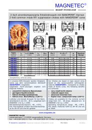
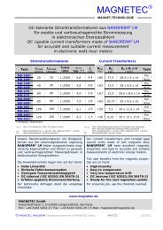
COOL BLUE � Ringbandkerne zur Reduzierung von Motorlagerströmen<br />
COOL BLUE � Tape wound cores to reduce motor-bearing currents<br />
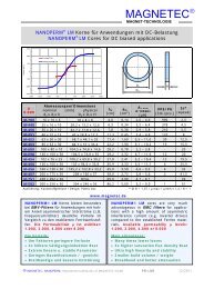
COOL BLUE� Ringbandkerne aus dem nanokristallinen<br />
Werkstoff NANOPERM� werden<br />
vermehrt zur Reduzierung von schädlichen<br />
Motorlagerspannungen/-strömen bei<br />
Umrichter-Antriebssystemen hoher Leistung<br />
und/oder hohen Taktfrequenzen eingesetzt.<br />
Durch die unerwünschten Lagerströme<br />
kommt es zur Mattierung und zur Riffelbildung<br />
der Motorlager, zum Durchschlag der<br />
Lagerschmierung und schließlich zum Ausfall<br />
des kompletten Motors.<br />
Durch gezielten Einsatz von COOL BLUE�<br />
Ringbandkernen werden - neben der Reduzierung<br />
der Überspannungen an den Motorklemmen<br />
- auch die durch parasitäre Ableitkapazitäten<br />
des Motorkabels und des Motors<br />
verursachten asymmetrischen Störströme<br />
signifikant unterdrückt. Dazu müssen lediglich<br />
die Verbindungsleitungen im DC-Zwischenkreis<br />
oder am Umrichter-Ausgang gemeinsam<br />
durch einen oder mehrere COOL<br />
BLUE� <strong>Kerne</strong> mit geeigneter Geometrie geführt<br />
werden. Die Wirkung entspricht der<br />
einer Gleichtakt-Drossel.<br />
Dadurch wird die Lebenslaufzeit der eingesetzten<br />
Motorlager wesentlich verlängert und<br />
Ausfallzeiten sowie hohe Kosten durch<br />
Anlagenstillstand bzw. Wartung vermieden.<br />
www.magnetec.de<br />
COOL BLUE� tape wound cores made from the<br />
nanocrystalline material NANOPERM� are<br />
being used increasingly to reduce damaging<br />
motor bearing currents in modern high power<br />
inverter systems operating at high switching<br />
frequencies.<br />
As a result of these unwanted currents, the<br />
bearings corrugate, leading to electrical breakdown<br />
in the lubrication and finally to a standstill<br />
of the entire motor.<br />
The use of COOL BLUE� cores not only significantly<br />
reduces the over voltage peaks at the<br />
motor terminals, but also suppresses the asymmetrical<br />
EMI currents which are generated by<br />
the parasitic capacities of the motor itself<br />
together with the motor cable. In order to<br />
achieve an efficient reduction in these destructive<br />
effects, one or more COOL BLUE� cores of<br />
suitable geometry have to be placed over the<br />
connector cables in the DC-link or at the<br />
inverter output. In this configuration, the cores<br />
operate as a common-mode choke.<br />
This method significantly increases the service<br />
life of the motor bearings and thus reduces<br />
maintenance costs and standstill periods.<br />
<strong>MAGNETEC</strong> <strong>GmbH</strong><br />
Industriestrasse 7, D-63505 Langenselbold, Germany<br />
Fon: +49 6184 9202 0 / Fax: +49 6184 9202 20 / E-Mail: magnetec@magnetec.de<br />
� <strong>MAGNETEC</strong>, NANOPERM; COOL BLUE: Registered trademarks of <strong>MAGNETEC</strong> <strong>GmbH</strong> PB-CB1 12/2011
<strong>MAGNETEC</strong> �<br />
MAGNET-TECHNOLOGIE<br />
COOL BLUE � Ringbandkerne zur Reduzierung von Motorlagerströmen<br />
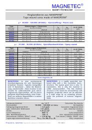
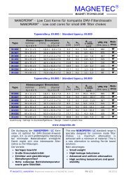
Type<br />
COOL BLUE � tape wound cores to reduce motor-bearing currents<br />
Abmessungen/Dimensions<br />
nominal [mm] physical<br />
da x di x h Da x Di x H<br />
lfe<br />
[cm]<br />
afe<br />
[cm 2 ]<br />
AL<br />
@ 10kHz<br />
[µH]<br />
IS<br />
Peak<br />
M-112 63 x 50 x 30 68 x 43 x 36 17,7 1,44 23,3 – 46,6 3<br />
M-649 63 x 50 x 30 OVAL 17,7 1,44 23,3 – 46,6 3 -<br />
M-378 75 x 50 x 30 80 x 43 x 36 19,4 2,78 37,3 – 74,6 3,5 -<br />
M-113 80 x 63 x 30 85 x 57 x 35,5 22,4 1,86 24,1 – 48,2 4<br />
M-283 80 x 63 x 30 OVAL 22,4 1,86 24,1 – 48,2 4<br />
M-114 100 x 80 x 30 105 x 75 x 35 28,2 2,25 22,5 – 45,0 5<br />
M-284 100 x 80 x 30 OVAL 28,2 2,25 22,5 – 45,0 5<br />
M-115 130 x 100 x 30 135 x 94 x 34 35,9 3,33 24,6 – 52,9 6,5<br />
M-116 160 x 130 x 30 165 x 123 x 34 45,4 3,24 20,9 – 45,0 8,5<br />
M-302 160 x 130 x 30 OVAL 44,7 3,30 20,9 – 45,0 8,5<br />
M-117 200 x 175 x 30 208 x 166 x 37 58,8 2,74 12,3 – 24,6 11<br />
M-111 236,5 x 201 x 30 OVAL 69,6 3,94 14,5 – 29,9 13<br />
M-205 300 x 254 x 30 304 x 246 x 36 87,1 5,20 15,8 – 31,5 16,5<br />
M-248 300 x 254 x 30 OVAL 87,1 5,20 15,8 – 31,5 16,5<br />
M-503 500 x 450 x 30 513 x 437 x 37 149,1 5,60 8,0 – 20,0 28<br />
Betriebstemperaturbereich: -40...+120°C,<br />
Temperaturklasse F, Isolierstoffklasse B (IEC<br />
85). Die <strong>Kerne</strong> sind in Kunststoffgehäusen<br />
fixiert, die mind. die Brennbarkeitsklasse UL-<br />
94 HB erfüllen.<br />
Dimensionierung:<br />
Je Antrieb werden etwa 4 <strong>Kerne</strong> benötigt,<br />
dabei sind die Kabel ohne Schirm durch die<br />
<strong>Kerne</strong> zu führen. Die Kernauswahl erfolgt in<br />
erster Linie über die Kabelgeometrie. Wenn<br />
möglich, sollte vor der Montage der <strong>Kerne</strong> der<br />
Peak-Gleichtaktstrom gemessen werden.<br />
Überschreitet der ermittelte Wert den in der<br />
Tabelle angegebenen IS, sollte zunächst die<br />
Kernanzahl erhöht werden. Ggf. muss eine<br />
größere Kerngeometrie verwendet werden.<br />
Ohne CB <strong>Kerne</strong> /<br />
Without CB cores<br />
Mit CB <strong>Kerne</strong>n /<br />
With CB cores<br />
� <strong>MAGNETEC</strong>, NANOPERM; COOL BLUE: Registered trademarks of <strong>MAGNETEC</strong> <strong>GmbH</strong> PB-CB2 12/2011<br />
[A]<br />
Webshop<br />
Operating temperature range: -40…+120°C,<br />
temperature class F, isolation class B (IEC 85).<br />
The cores are protected by plastic cases, the<br />
plastic material fulfills minimum UL-94 HB.<br />
Design:<br />
Per each motor drive roughly 4 cores are<br />
required. The conductors excl. shielding have<br />
to be put through the cores. The conductor<br />
size defines the inner core diameter. If<br />
possible the peak common-mode current<br />
should to be measured before assembling the<br />
cores. If the peak current exceeds the IS value<br />
shown in above table, the number of cores<br />
should be increased first. If necessary a bigger<br />
core size has to be be chosen.