Solar Inverter SI 3300 - ET SolarPower GmbH
Solar Inverter SI 3300 - ET SolarPower GmbH
Solar Inverter SI 3300 - ET SolarPower GmbH

Erfolgreiche ePaper selbst erstellen
Machen Sie aus Ihren PDF Publikationen ein blätterbares Flipbook mit unserer einzigartigen Google optimierten e-Paper Software.
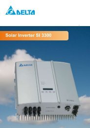
<strong>Solar</strong> <strong>Inverter</strong> <strong>SI</strong> <strong>3300</strong><br />
Operating and installation manual (1-32)<br />
Bedienungsanleitung (33-64)
Table of Contents<br />
1 Scope of delivery 2<br />
2 General / Notes on safety 2<br />
3 Introduction 3<br />
4 System 3<br />
4.1 Data evaluation and communication 4<br />
4.2 Technical structure of the solar inverter 4<br />
4.3 Equipment overview 5<br />
5 Installation 6<br />
6 Installation of equipment 6<br />
6.1 Installation location 6<br />
6.2 Minimum requirements 6<br />
6.3 Maintenance 7<br />
6.4 Installation 7<br />
6.5 Ambient temperature 8<br />
6.6 Network connection 8<br />
6.7 Connection of PV modules 9<br />
6.7.1 <strong>Solar</strong> inverter range 0<br />
6.7.2 Efficiency 1<br />
6.8 Interface connection RS485 (EIA485) 1<br />
6.9 Electrical connection and operational start-up 3<br />
6.10 LED operation and fault display 4<br />
7 Operating concept 5<br />
7.1 The display 5<br />
7.2 Navigation in the display 5<br />
7.3 Main menu 6<br />
7.3.1 Submenu N (Now) 7<br />
7.3.2 Submenu D (Day) 7<br />
7.3.3 Submenu W (Week) 8<br />
7.3.4 Submenu M (Month) 8<br />
7.3.5 Submenu Y (Year) 8<br />
7.3.6 Submenu T (Total) 9<br />
7.3.7 Submenu S (Setup) 9<br />
8 Diagnostics and data evaluation 20<br />
8.1 Malfunction rectification 20<br />
8.2 Display messages 20<br />
9 Technical Data 22<br />
10 Appendix 23<br />
10.1 Connection examples 23<br />
10.2 Overview of connection diagrams 24<br />
11 Glossary 26<br />
12 Certificates 28
1 Scope of delivery<br />
• <strong>Solar</strong> <strong>Inverter</strong><br />
• Mounting plate<br />
• Operating and installation manual<br />
• AC connector<br />
2 General / Notes on safety<br />
Dear Customer,<br />
Congratulations on the purchase of this technically high-quality solar inverter.<br />
These directions will help you become familiar with this product.<br />
Please consider the safety regulations (VDE, VDEW, BGFE, technical connection conditions for<br />
local utility company). Careful handling with your product will contribute to its service life durability<br />
and reliability. These are essential prerequisites for maximum yield.<br />
Please consider the following notes on safety:<br />
• During operation of electrical devices, certain parts are under dangerous voltage.<br />
• Inappropriate handling can lead to physical injury and material damage!<br />
• Adhere to the installation regulations.<br />
• Installation and operational start-up work may be implemented only through qualified electrical<br />
experts.<br />
• Repair work on the device may be carried out by the manufacturer only.<br />
• Please consider all points in the operating and installation manual!<br />
• Isolate the device from the mains and the PV modules before carrying out any work on it.<br />
• As a result of very high temperatures, the device surface area can become hot.<br />
• Sufficient cooling is necessary.<br />
• As the solar inverter is heavy (weight > 18 kg) it should be lifted by at least two persons.<br />
• Remember that the unit has a high leakage current. The PE conductor MUST be connected prior<br />
to commencing operation.<br />
Do not open the solar inverter. No user serviceable parts. Risk of electrical<br />
hazard and invalidated warranty.<br />
Dangerous voltage present for 5 minutes after disconnecting all sources of<br />
power.<br />
© Copyright – Delta Energy Systems (Germany) <strong>GmbH</strong> - All rights reserved.<br />
This manual accompanies our equipment for use by the end users.<br />
The technical instructions and illustrations contained in this manual are to be treated as confidential and no part may be reproduced<br />
without the prior written permission of Delta Energy Systems Service engineers and end users may not divulge the information<br />
contained herein or use this manual for purposes other than those strictly connected with correct use of the equipment.<br />
All information and specifications are subject to change without notice.
3 Introduction<br />
With this device you have acquired a solar inverter for the mains connection of photovoltaic systems.<br />
This solar inverter is characterized by its advanced housing design and state-of-the-art radio<br />
frequency technology, which enable the highest levels of efficiency.<br />
The solar inverter includes series monitoring units, such as ENS, display and RS485 (EIA485)<br />
interface.<br />
The inverter is usable indoors and outdoors. It fulfills the directives of the VDEW (Union of German<br />
Electrical Power Stations) for parallel operation of power generation plants on low-voltage network<br />
of regional electrical utility companies.<br />
The function of the ENS (automatic isolation point for in-plant generation systems) stipulates compliance<br />
with the specifications of DIN VDE 0126-1-1 and compliance with the low-voltage guideline.<br />
These are declared through the attached GS-Innova character and the CE mark (see page 28,<br />
section 12).<br />
In the following technical description, the precise functions are explained to the installer, as well<br />
as the user, which are required for the installation, operational start-up and handling of the solar<br />
inverter.<br />
4 System<br />
The content of renewable energy with respect to overall power consumption worldwide is increasing<br />
annually by approx. 25%. The reason for this rise can be primarily attributed to the constantly<br />
increasing demand for power, the increasing interest in environmentally friendly technologies, as<br />
well as the increasing costs of non-renewable energy.<br />
By the use of renewable energy sources, the earth’s atmosphere can be enormously relieved of<br />
increases in CO 2<br />
and other harmful gases which result from power generation.<br />
The solar inverter converts direct current from the solar cells into alternating current. This enables<br />
you to feed your self-produced solar energy into the public mains.<br />
Thanks to efficient MPP tracking, maximum capacity utilization of the solar energy plant is ensured<br />
even in case of a misty and clouded over sky.<br />
The string concept means that PV modules are always connected in series (in a string) and/or that<br />
strings with the same voltage are connected in parallel to the solar inverter with the aim of significantly<br />
reducing the photovoltaic system’s cabling requirements.<br />
The fact that the modules are connected in strings also means that the photovoltaic system can be<br />
perfectly matched to the solar inverter’s input voltage range.
4.1 Data evaluation and communication<br />
The integrated data display, processing and communication of the device enables easy operation<br />
of the solar inverter. Monitoring of the operational status and signaling of operational failures are<br />
capable of being called up over the device display. The data interfaces enable the downloading of<br />
data which can be evaluated with the aid of a PC system and thus guarantees continuous recording<br />
of operating data.<br />
The best way of accessing this functionality is via the available accessories (e.g. WEB´log);<br />
comprehensive and seamless solar inverter monitoring is ensured.<br />
The read-out of the data over the integrated interface and the display is possible only in solar operation.<br />
4.2 Technical structure of the solar inverter<br />
A potential isolation of the solar inverter from the mains network is achieved through a radio frequency<br />
converter with integrated transformer. The photovoltaic voltage is adjusted so that the maximum<br />
power output of the PV modules is also achieved with different solar irradiation levels and<br />
temperatures (MPP-Tracking).<br />
The MPP range of the solar inverter is between 150 V and 450 V. This facilitates the use of PV<br />
modules by a variety of manufacturers. Measures must be taken to ensure that the maximum noload<br />
voltage of 540 V is never exceeded. Please note that the maximum no-load voltage will occur<br />
at the lowest temperatures anticipated. You will find more detailed information about temperature<br />
dependency in the data sheet for the PV modules.<br />
The device’s power consumption is kept to a minimum.<br />
The high-quality aluminum casing corresponds to Protection Type IP65 (water-jet-proof and dustproof)<br />
and is protected against weathering processes by surface refinement. The cooling characteristic<br />
profile is designed so that operation of the inverter is possible with ambient temperatures<br />
from -25°C to +70°C.<br />
A cooling characteristic profile is used for the removal of the power dissipation caused through<br />
the voltage conversion. An internal temperature control protects the device against too high temperatures<br />
in the interior of the solar inverter. In case of high ambient temperatures, the maximum<br />
transferable power is limited (see diagram under 6.5).<br />
The solar inverter is controlled by microcontrollers, which also implement interface communication<br />
and the displays of values and messages on the display.<br />
Two independent and redundant microcontrollers control the monitoring of the network, which is<br />
consistent with the feed-in directives of VDEW and DIN 0126-1-1 (ENS). This enables an installation<br />
of the solar inverter in the in-house mains network.<br />
Operator protection requirements are met by electrically isolating the mains from the PV module.<br />
The electrical isolation between the mains and the PV module is equivalent to basic insulation.<br />
Maximum operator protection is ensured by reinforced isolation between the mains, PV modules<br />
and accessible interfaces (display, RS485 interface and fan port). Relevant standards concerning<br />
electromagnetic compatibility (EMC) and safety are fulfilled.<br />
The solar inverter is functional in network parallel operation exclusively. An automatically-acting<br />
isolation point, which was accepted by a certification agency, guarantees secure disconnection in<br />
case of circuit isolation or interruptions in power supply and avoids isolated operation.
The equipment provided for the disconnection is a so-called „automatic isolation for in-plant generation<br />
systems of nominal power ≤ 4.6 kVA, with single-phase parallel feed-in over solar inverter into<br />
the mains network of the public supply“.<br />
4.3 Equipment overview<br />
(5)<br />
(4)<br />
(1) (2)<br />
(3)<br />
(1) Connections for PV modules<br />
(2) Mains connection<br />
(3) Interface connection RS485 (EIA485)<br />
(4) Display for status display and keyboard for operation<br />
(5) 3 light-emitting diodes for operating status display
5 Installation<br />
Installation and commissioning must only be carried out by qualified electrical experts!<br />
The prescribed safety regulations, the technical interface conditions (TAB 2000), as well as the VDE<br />
specification, are to be complied with.<br />
In order to be able to carry out an energy measurement, a meter must be attached between the<br />
network feed-in point and the solar inverter (in accordance with the VDEW directive concerning „Inplant<br />
generation systems on the low-voltage mains network“).<br />
By means of the integrated ENS, the function of the prescribed section switch is fulfilled in accordance<br />
with the VDEW directive. In case of ENS not being present, precautions must be provided<br />
through a section switch for the disconnection from the network, in accordance with above directive.<br />
Caution: The secondary short-circuit current rating is increased at the transfer connection point to<br />
the public electricity supply system by the nominal current of the connected solar inverter.<br />
6 Installation of equipment<br />
6.1 Installation location<br />
• Install the device on a non-inflammable support base.<br />
• Avoid installation on resonating bodies (light construction walls etc.).<br />
• Installation is possible both indoors and protected outdoor area.<br />
• An increased ambient temperature can reduce the efficiency of the PV system.<br />
• Noise generation possible (avoid installation in the residential area).<br />
• Ensure legibility of the LEDs and the display (read-off angle / installation height).<br />
• Although the unit is fitted with UV resistant components, direct exposure to sunlight should be<br />
avoided.<br />
• Despite having an IP65 enclosure and being certified in accordance with soiling category III, the<br />
unit must not be allowed to become too heavily soiled.<br />
• Heavy soiling can impair the unit’s performance.<br />
6.2 Minimum requirements<br />
• Free convection around the solar inverter must not be impaired.<br />
• For air circulation allow a clearance of approx. 10 cm to the side and approx. 50 cm above and<br />
below the unit.<br />
• The network impedance at the supply terminal is to be considered (cable length, cable crosssection).<br />
• The prescribed installation position is to be adhered to (vertical).<br />
• Unused DC connectors (Tyco) and interfaces must be shut through sealing connectors.<br />
50 cm<br />
Wall<br />
Wall<br />
10 cm<br />
10 cm<br />
50 cm
6.3 Maintenance<br />
Make sure that the device remains uncovered during the complete operating time.<br />
To avoid that the casing of the solar inverter becomes too heavily soiled, it should be cleaned from<br />
time to time.<br />
User serviceable parts are not contained in the device. Under no circumstances the solar inverter<br />
should be opened!<br />
6.4 Installation<br />
You should employ the delivered mounting plate for problem-free installation of the solar inverter.<br />
The attachment on the wall should be implemented with adequate hexagonal bolts or socket bolts.<br />
Mount the wall bracket so that the solar inverter only has to be simply attached at a later time. After<br />
that, the device is to be bolted on securely.<br />
Assembly instructions<br />
1. Mount the mounting plate. Insert M10 screws (or larger) into at least four of the eight<br />
holes to fix the wall bracket in place. You can employ the mounting plate as a drill template<br />
for marking the positions for the boreholes.<br />
2. As the solar inverter weighs 21.5 kg, it should be lifted out of the transport crate by at<br />
least two persons.<br />
3. Place the solar inverter onto the mounting plate with at least two persons.<br />
4. Fasten the supplied mounting nuts and washers on the threaded bolt intended for securing<br />
the device.<br />
5. Check the solar inverter for secure seating.<br />
Mounting<br />
plate<br />
200<br />
320<br />
t=2,5<br />
6.5<br />
Ø 12.5<br />
90<br />
12<br />
38<br />
12<br />
Locking screw<br />
150<br />
319.5<br />
410 ± 0.5<br />
Locking screw
6.5 Ambient temperature<br />
The solar inverter can be operated in an ambient temperature between -25°C to +70°C.<br />
The following diagram illustrates how the power supplied by the solar inverter is reduced automatically<br />
in accordance with ambient temperature.<br />
The device should be installed in a well-ventilated, cool and dry location.<br />
3600<br />
<strong>3300</strong><br />
3000<br />
2700<br />
2400<br />
AC Power (W)<br />
2100<br />
1800<br />
1500<br />
1200<br />
900<br />
600<br />
300<br />
0<br />
30.0 40.0 50.0 60.0 70.0 80.0<br />
Ambient temperature (°C)<br />
PV Voltage 150V<br />
PV Voltage 270V<br />
PV Voltage 400V<br />
6.6 Network connection<br />
The network (AC output) is connected over a Wieland RST25i3S AC connector. You can find the<br />
correct allocation on the screw-type terminal connection of the connector. The solar inverter must<br />
be connected to the network over a three-core line (L, N, PE). The connected AC line must be<br />
switched potential-free before the disconnection or the insertion of the AC connector.<br />
The connection to the Wieland AC connector must be implemented with a flexible line and a conductor<br />
cross section of min. 2.5 mm² to max. 4.0 mm².<br />
An automatic circuit breaker is to be provided in the line L upstream of every device, with a nominal<br />
current of 25 A and tripping characteristic Type B. In addition, attention is to be paid to the selectivity<br />
of the fuse unit attached upstream of the automatic system.<br />
The solar inverter must be earthed via the AC connector’s PE conductor. To do this, connect the PE<br />
conductor to the designated terminal. If you wish to integrate more than one inverter into the installation,<br />
please proceed as illustrated in the drawings in the appendix.<br />
Please note the cable length and the cable cross-section, due to the risk of undesirable temperature<br />
rise and power losses.<br />
The AC connector is protected from unintentional disconnection by a clip mechanism which can be<br />
released with a screwdriver.
6.7 Connection of PV modules<br />
Before the photovoltaic system is connected, the polarity of the PV voltage at the Tyco connectors<br />
must be checked to ensure that it is correct. The connectors are colour-coded red (+) and blue (-).<br />
The connection of the PV module is implemented using a Tyco <strong>Solar</strong>lok connector, where the minus<br />
pole is located on the connector upper row and the positive pole on the connector lower row.<br />
The connectors are coded to prevent you from accidentally plugging them into the wrong terminal.<br />
Please ensure the following at all times:<br />
• that there is never any risk of anyone coming into contact with the solar inverter connection<br />
terminals, due to the risk of dangerous voltages across them.<br />
• that under no circumstances the PV modules are disconnected from the solar inverter under<br />
load. If a disconnection should be necessary, first switch the network off so that the solar inverter<br />
cannot absorb any further power. Next, open the upstream DC disconnect switch.<br />
The solar inverter is equipped with the connector connection system from the company Tyco. The<br />
maximum input voltage of the solar inverter is 540 V. The maximum current load of each individual<br />
Tyco connector is 25 A.<br />
The solar inverter has an insulation and grounding monitoring on the DC side. The options can be<br />
configured in the Setup menu “6. S -> <strong>Solar</strong> ISO / GND” (see page 19, section 7.3.7).<br />
The insulation monitoring has two modes:<br />
• ISO-ON-Error (the solar inverter is disconnected from the mains in the event of an insulation<br />
fault)<br />
• ISO-ON-Warning (the solar inverter indicates the fault but is not disconnected from the mains).<br />
Deltas solar inverters are factory-set to ISO-ON-Warning mode on delivery.<br />
The grounding monitoring has two modes:<br />
• PV+ grounding (grounding monitoring of the positive pole of the PV generator)<br />
• PV- grounding (grounding monitoring of the negative pole of the PV generator).<br />
In these modes the solar inverter remains in feed-in operation and will not be disconnected from<br />
the mains in case of a fault. The error message “PV+ grounding fault” or “PV- grounding fault” will<br />
appear on the display.<br />
If you need to connect the positive or negative pole of the PV system to meet requirements set<br />
out by the module manufacturer, you can do this. Earth continuity must be implemented close to<br />
the inverter. We suggest using Deltas grounding kit “Grounding Set A <strong>Solar</strong>” (EOE 99000115). The<br />
grounding connection is monitored and should be configured in the Setup menu (see above).<br />
Alternatively, it is possible to turn off the insulation- and grounding monitoring:<br />
• ISO / GND OFF.
Cable<br />
coupler<br />
polarity<br />
Wire size<br />
2.5 mm 2<br />
(AWG 14)<br />
Wire size<br />
4.0 mm 2<br />
(AWG 12)<br />
Wire size<br />
6.0 mm 2<br />
(AWG 10)<br />
Female cable<br />
coupler<br />
Plus coded<br />
Female cable<br />
coupler<br />
Minus coded<br />
Tyco<br />
Order<br />
number<br />
Plus<br />
coupler • •<br />
1394462-1<br />
Minus<br />
coupler • •<br />
1394462-2<br />
Plus<br />
coupler • •<br />
1394462-3<br />
Minus<br />
coupler • •<br />
1394462-4<br />
Plus<br />
coupler • •<br />
1394462-5<br />
Minus<br />
coupler • •<br />
1394462-6<br />
6.7.1 <strong>Solar</strong> inverter range<br />
Energrid <strong>3300</strong><br />
Please consider the following limit curve diagram of the solar inverter:<br />
Maximale Ausgangsleistung als Funktion der Eingangsspannung<br />
3500<br />
3400<br />
<strong>3300</strong><br />
3200<br />
Output Ausgangsleistung power (W) / W<br />
3100<br />
3000<br />
2900<br />
2800<br />
2700<br />
2600<br />
2500<br />
125 150 175 200 225 250 275 300 325 350 375 400 425 450<br />
Spannung der PV Module / V<br />
Voltage of PV Modules (V)<br />
10
6.7.2 Efficiency<br />
The best efficiency of the solar inverter is obtained at input voltages >250 V.<br />
98,0<br />
96,0<br />
94,0<br />
Efficiency (%)<br />
92,0<br />
90,0<br />
88,0<br />
86,0<br />
84,0<br />
82,0<br />
80,0<br />
0 500 1000 1500 2000 2500 3000 3500<br />
Output power (W)<br />
PV Voltage 150V<br />
PV Voltage 275V<br />
PV Voltage 400V<br />
6.8 Interface connection RS485 (EIA485)<br />
The interfaces not used must always be closed off. In case of utilization of an interface, only the<br />
counterpart fitting the interface connector is to be employed.<br />
Mating connector supplier HARTING Deutschland <strong>GmbH</strong> & Co. KG (P.O. 2451, D-32381 Minden;<br />
www.harting.com).<br />
Order designation: 09 45 145 1510, Cable Manager Blue IP67 Push-Pull Data Plug<br />
09 45 145 1500, Cable Manager White IP67 Push-Pull Data Plug<br />
-<br />
-<br />
-<br />
-<br />
~<br />
~<br />
~<br />
~<br />
RS485 (EIA485)<br />
terminating resistor<br />
230 V - House connection line<br />
RS485 (EIA485) - Connection<br />
Datalogger<br />
11
Connector pin assignment RS485 (EIA485)<br />
Pin<br />
Top View<br />
8 1<br />
1 Not used<br />
2 Not used<br />
3 Not used<br />
4 GND (RS485)<br />
5 TERM (RS485)<br />
6 RX_B (RS485)<br />
7 TX_A (RS485)<br />
8 Not used<br />
When several devices are connected in series and the total length of the data line measures 2 m or<br />
more, the following options are available for terminating the RS485 (EIA485) interface:<br />
+5V<br />
Not used<br />
0R<br />
0R<br />
TX_A<br />
RX_B<br />
Pin 7<br />
Pin 6<br />
100 ... 150<br />
Ohm, 0,25W<br />
Not used<br />
121R<br />
TERM<br />
GND<br />
+5V<br />
Not used<br />
0R<br />
TX_A<br />
RX_B<br />
0R<br />
Pin 6<br />
Not used<br />
121R<br />
TERM<br />
GND<br />
Pin 5<br />
12
BFS<br />
Power<br />
Controller<br />
ENS<br />
Communication<br />
Operating- and System Control<br />
DC<br />
String A<br />
String B<br />
String C<br />
DC<br />
DC<br />
MPP-<br />
Tracker<br />
-<br />
Booster<br />
-<br />
Isolation<br />
-<br />
-<br />
DC-Bus<br />
-<br />
~<br />
AC<br />
Public<br />
mains<br />
String D<br />
DC<br />
<strong>Solar</strong> <strong>Inverter</strong><br />
6.9 Electrical connection and operational start-up<br />
The solar inverter is delivered in an operable status.<br />
The electrical connection is implemented on this solar inverter using the connector contacts which<br />
are attached to the casing. In no case must the device be opened!<br />
13
In order to connect the device electrically, the following procedures must be followed:<br />
1. DC connection: First, connect the PV module strings to the DC disconnect switch (not included<br />
in the scope of delivery).<br />
2. Connect the DC disconnect switch to the solar inverter (ensure correct polarity).<br />
3. AC connection: Next, connect the AC connector to the solar inverter and then to the mains.<br />
4. Before switching on the power, check all feeders and connections one last time.<br />
5. Close DC disconnect.<br />
6. Close automatic cutouts on the input side.<br />
7. In case of sufficient PV voltage (UPV > 150 V), the device now goes into the start-up mode.<br />
8. In case of a new installation the time and date have to be set in sub-menu S (Setup) (see page<br />
19, section 7.3.7).<br />
All unoccupied connectors and interfaces must be shut off airtight using the delivered<br />
seals.<br />
6.10 LED operation and fault display<br />
Three light-emitting diodes (LEDs), which display the operational state of the solar inverter, are attached<br />
on the front:<br />
Operation (A)<br />
Earth Fault (B)<br />
Failure (C)<br />
• LED (A), green: „Operation“ displays the<br />
operational state.<br />
• LED (B), red: „Earth Fault“ displays an insulation<br />
resistance fault or PV grounding (GND)<br />
fault on the DC side.<br />
• LED (C), yellow: „Failure“ displays existing<br />
faults internally or externally and whether the<br />
network feed-in operation has been interrupted.<br />
LED Status Operational state Explanation<br />
green: <br />
red: <br />
yellow: <br />
green: <br />
red: <br />
yellow: <br />
green: <br />
red: <br />
yellow: <br />
Night disconnection.<br />
Initialization.<br />
Input- and grid<br />
monitoring.<br />
The input voltage (UPV) is lower than 100 V.<br />
The solar inverter is not feeding power to the grid.<br />
Input voltages:<br />
UPV: 100 V to 150 V<br />
(self test ongoing).<br />
Starting conditions are tested.<br />
14
LED-Status Operational state Explanation<br />
green: <br />
red: <br />
yellow: <br />
green: <br />
red: <br />
yellow: <br />
green: <br />
red: <br />
yellow: <br />
green: <br />
red: <br />
yellow: <br />
Feed-in operation.<br />
Equipment fault.<br />
General error<br />
condition.<br />
Warning message.<br />
Normal operational state:<br />
UPV: 150 V to 540 V.<br />
Internal or external fault<br />
(interrupted feed).<br />
See also display messages!<br />
<strong>Solar</strong> inverter is not connected to the grid.<br />
No power is delivered.<br />
See also display messages!<br />
You can carry on using the solar inverter.<br />
See also display messages!<br />
7 Operating concept<br />
7.1 The display<br />
The delivery of the solar inverter is implemented ready for operation. No presetting adjustments are<br />
therefore necessary for the user.<br />
The display on the device indicates different information. The enter keys are used for the adjustment<br />
of the device and for the call-up of information. The indicated measuring data can deviate with a<br />
tolerance of up to 5%.<br />
Key (A), ESC:<br />
To switch from the menu<br />
items to the main menu and<br />
to exit each sub-menu.<br />
(A) (B) (C) (D)<br />
ESC<br />
Key (B) and (C): For scrolling in the individual<br />
menu items and/or carrying<br />
out adjustments in the setup<br />
menu.<br />
Key (D), ENTER: ENTER key for changing into<br />
the menu levels and for input<br />
acknowledgement in the<br />
setup menu.<br />
7.2 Navigation in the display<br />
Lighting of the display<br />
Through pressing the ENTER key in automatic operation, the display lighting is implemented. If no<br />
key should be activated within 30 seconds, the display lighting automatically goes out. The setup<br />
menu enables selection between continuous or automatic lighting. Through pressing the ENTER<br />
key, the display lighting is switched on again.<br />
15
7.3 Main menu<br />
The main menu consists of 7 menu items which are subdivided into submenus:<br />
• Menu N (Now)<br />
• Menu D (Day)<br />
• Menu W (Week)<br />
• Menu M (Month)<br />
• Menu Y (Year)<br />
• Menu T (Total)<br />
• Menu S (Setup)<br />
Handling of the menu items:<br />
You can scroll the main menu by activating the selector keys .<br />
Press the ENTER key to select the submenus. In order to exit the menus again, activate the ESC<br />
key.<br />
ESC<br />
ENTER<br />
1. Menu - N<br />
Now (act. Data)<br />
Sub Menu<br />
2. Menu - D<br />
Day Statistic<br />
Sub Menu<br />
3. Menu - W<br />
Week Statistic<br />
Sub Menu<br />
4. Menu - M<br />
Month Statistic<br />
Sub Menu<br />
5. Menu - Y<br />
Year Statistic<br />
Sub Menu<br />
6. Menu - T<br />
Total Statistic<br />
Sub Menu<br />
7. Menu - S<br />
Setup <strong>Inverter</strong><br />
Sub Menu<br />
16
7.3.1 Submenu N (Now)<br />
This menu item displays the instantaneous values.<br />
ESC<br />
ENTER<br />
1. Menu - N<br />
Now (act. Data)<br />
1. N -> AC-Power<br />
xxxx W<br />
2. N -> AC-Voltage<br />
xxx V<br />
3. N -> AC-Current<br />
xx.x A<br />
4. N -> AC-Frequency<br />
xx.xx Hz<br />
5. N -> <strong>Solar</strong>-Voltage<br />
xxx V<br />
6. N -> <strong>Solar</strong>-Current<br />
xx.x A<br />
7. N -> Time<br />
HH:MM:SS<br />
8. N -> Date<br />
WD, DD.MM.YYYY<br />
Display of the<br />
active output power<br />
Display of the active<br />
output voltage<br />
Display of the active<br />
output current<br />
Display of the active<br />
mains frequency<br />
Display of the active<br />
solar cell voltage<br />
Display of the active<br />
solar cell current<br />
Display of the<br />
current time<br />
Display of current day<br />
of the week and date<br />
7.3.2 Submenu D (Day)<br />
This menu item displays the daily values for the mains feed.<br />
ESC<br />
ENTER<br />
1. Menu - D<br />
Day Statistic<br />
1. D -> Energy<br />
xxxx Wh<br />
Display of the daily<br />
energy gain<br />
2. D -> Revenue<br />
xxxxx.xx Euro<br />
3. D -> AC-Power-Max.<br />
xxxx W<br />
4. D -> AC-Volt.-Max.<br />
xxx V<br />
5. D -> AC-Volt.-Min.<br />
xxx V<br />
6. D -> AC-Curr-Max.<br />
xx.x A<br />
7. D -> AC-Freq.-Max.<br />
xx.xx Hz<br />
8. D -> AC-Freq.-Min.<br />
xx.xx Hz<br />
9. D -> Runtime<br />
xxx min.<br />
Display of the daily revenue<br />
Display of the daily<br />
maximum output power<br />
Display of the daily max.<br />
output voltage<br />
Display of the daily min.<br />
output voltage<br />
Display of the daily<br />
maximum output current<br />
Display of the daily<br />
maximum output frequency<br />
Display of the daily<br />
minimum output frequency<br />
Display of the daily operating<br />
time of the solar inverter<br />
17
7.3.3 Submenu W (Week)<br />
This menu item displays the average values of the current week.<br />
ESC<br />
ENTER<br />
1. Menu - W<br />
Week Statistic<br />
1. W -> Energy<br />
xxxx.x kWh<br />
Display of the weekly<br />
energy gain<br />
2. W -> Revenue<br />
xxxxx Euro<br />
Display of the weekly revenue<br />
3. W -> Runtime<br />
xxxx h<br />
Display of the weekly operating<br />
time of the solar inverter<br />
7.3.4 Submenu M (Month)<br />
This menu item displays the average values of the current month.<br />
ESC<br />
ENTER<br />
1. Menu - M<br />
Month Statistic<br />
1. M -> Energy<br />
xxxx.x kWh<br />
Display of the monthly<br />
energy gain<br />
2. M -> Revenue<br />
xxxxx Euro<br />
3. M -> Runtime<br />
xxxx h<br />
Display of the monthly revenue<br />
Display of the monthly operating<br />
time of the solar inverter<br />
7.3.5 Submenu Y (Year)<br />
This menu item displays the average values of the current year.<br />
ESC<br />
ENTER<br />
1. Menu - Y<br />
Year Statistic<br />
1. Y -> Energy<br />
xxxx.x kWh<br />
Display of the annual<br />
energy gain<br />
2. Y -> Revenue<br />
xxxxx Euro<br />
Display of the annual revenue<br />
3. Y -> Runtime<br />
xxxx h<br />
Display of the annual operating<br />
time of the solar inverter<br />
18
7.3.6 Submenu T (Total)<br />
This menu item shows cumulated and maximum/minimum values since first use.<br />
ESC<br />
ENTER<br />
1. Menu - T<br />
Total Statistic<br />
1. T -> Energy<br />
xxxx.x kWh<br />
2. T -> Revenue<br />
xxxxx Euro<br />
3. T -> Sol.-Vol.-Max.<br />
xxx V<br />
4. T -> Sol.-Cur.-Max.<br />
xx.x A<br />
5. T -> Sol.-Pow.-Max.<br />
xxxx W<br />
6. T -> Isolation-Max.<br />
xxxx kOhm<br />
7. T -> Isolation-Min.<br />
xxxx kOhm<br />
8. T -> Runtime<br />
xxxx h<br />
Display of the total<br />
energy gain<br />
Display of the total<br />
revenue<br />
Display of the max.<br />
solar cell voltage<br />
Display of the max.<br />
solar cell current<br />
Display of the max.<br />
solar cell power<br />
Display of the largest<br />
insulation resistance<br />
Display of the smallest<br />
insulation resistance<br />
Display of the total operating<br />
time of the solar inverter<br />
7.3.7 Submenu S (Setup)<br />
This menu item is used for changing the presettings of the solar inverter.<br />
ESC<br />
ENTER<br />
1. Menu - S<br />
Setup <strong>Inverter</strong><br />
1. S -> LCD-Contrast<br />
2. S -> LCD-Backlight<br />
0 ... 9<br />
Auto / On<br />
Adjustment of the brightness of<br />
the LCD display between 0 ... 9<br />
Adjustment of the LCD<br />
background lighting<br />
3. S -> Menu-Mode<br />
Now ... Setup<br />
Selection of the start menu<br />
on restart of the device<br />
4. S -> Cash per kWh<br />
xx.xx Euro<br />
Entry of feed-in remuneration in €/kWh<br />
5. S -> ID-Number<br />
001 ... 254<br />
Input of the ID number of the solar inverter<br />
6. S -> <strong>Solar</strong> ISO /<br />
GND<br />
ISO-ON-Warning<br />
ISO-ON-Error<br />
ISO / GND OFF<br />
PV+ grounded<br />
PV- grounded<br />
ISO / GND Setup Menu<br />
7. S -> Baudrate<br />
2400 ... 38400<br />
Adjustment of the baud rate<br />
between 2400 ... 38400 Baud<br />
8. S -> Time<br />
HH:MM:SS<br />
Adjustment of the internal clock<br />
9. S -> Date<br />
WD, DD.MM.YYYY<br />
Adjustment of current day of the week and date<br />
10. S -> Firmware xx<br />
AC-Control x.xx<br />
AC controller<br />
xx shows the<br />
country code<br />
DC-Control x.xx<br />
DC controller<br />
ENS Master x.xx<br />
ENS board (for ENS version only)<br />
ENS Slave x.xx<br />
ENS board (for ENS version only)<br />
Display x.xx<br />
x.xx shows the<br />
revision of the<br />
firmware<br />
Display<br />
19
8 Diagnostics and data evaluation<br />
8.1 Malfunction rectification<br />
The solar inverter is provided with an automatic diagnostics system which independently identifies<br />
certain faults and which can make them visible externally on the display.<br />
Troubleshooting in the field<br />
In principle, it is always worth attempting a reset by reinitialising the solar inverter whenever an error<br />
message appears on the display.<br />
To reset the device, proceed as follows:<br />
1. Isolate the solar inverter from the mains (open automatic cutouts).<br />
2. Switch off DC main switch.<br />
3. Wait time: approx. 1 minute.<br />
4. Switch DC main switch back on.<br />
5. Switch in mains (close automatic cutouts).<br />
(In the field, the first step is to scan for potential fault causes that could be picked up by the solar<br />
inverter and result in tripping.)<br />
Various key parameters can be scanned via the display, thereby enabling conclusions to be drawn<br />
about potential fault causes.<br />
Current values in the N menu<br />
AC Voltage -> Display of current output voltage -> Voltage limiting values<br />
AC Frequency -> Display of current mains frequency -> Frequency limiting values<br />
<strong>Solar</strong> Voltage -> Display of current solar cell voltage -> Switch-in threshold<br />
8.2 Display messages<br />
LED Status<br />
Display<br />
message<br />
Cause<br />
Elimination<br />
green: <br />
red: <br />
yellow: <br />
-<br />
Display communication<br />
faulty.<br />
- If the fault persists after the device has<br />
been reset, please inform your service<br />
technician.<br />
green: <br />
red: <br />
yellow: <br />
AC frequency<br />
failure<br />
Mains frequency overshooting<br />
or undershooting<br />
specified limit range.<br />
- Check the mains frequency via the<br />
display in the N menu.<br />
green: <br />
red: <br />
yellow: <br />
AC voltage<br />
failure<br />
Mains voltage overshooting<br />
or undershooting<br />
specified limit range.<br />
- Check the mains voltage via the display in<br />
the N menu.<br />
- If no voltage present, check mains automatic<br />
cutouts.<br />
green: <br />
red: <br />
yellow: <br />
AC relay<br />
failure<br />
One of the ENS output<br />
relays is faulty / defective.<br />
- The solar inverter is defective.<br />
- Return the device.<br />
green: <br />
red: <br />
yellow: <br />
Calibration<br />
ongoing<br />
Check of internal settings.<br />
Normal function before input mode.<br />
green: <br />
red: <br />
yellow: <br />
DC injection<br />
failure<br />
DC component of inputside<br />
alternating current is<br />
too high.<br />
- If the fault persists after the device has<br />
been reset, please inform your service<br />
technician.<br />
20
LED Status<br />
Display<br />
message<br />
Cause<br />
Elimination<br />
green: <br />
red: <br />
yellow: <br />
Error # 301<br />
Internal communication<br />
error or hardware fault.<br />
- If the fault persists after the device has<br />
been reset, please inform your service<br />
technician.<br />
green: <br />
red: <br />
yellow: <br />
Error # 302<br />
The device trips and reverts<br />
to mains input mode<br />
once the temperature has<br />
dropped.<br />
- Check the installation site (no direct<br />
sunlight, air circulation).<br />
green: <br />
red: <br />
yellow: <br />
Error # 506<br />
Error # 508<br />
Isolation resistance fault<br />
on the DC side during<br />
start-up phase (# 508) or<br />
running phase (# 506).<br />
- Check the isolation resistance on the DC<br />
side of the solar modules.<br />
green: <br />
red: <br />
yellow: <br />
Isolation startup<br />
warning<br />
Isolation running<br />
warning<br />
Isolation resistance fault<br />
on the DC side during<br />
start-up phase or running<br />
phase.<br />
- You must check the isolation resistance<br />
on the DC side of the solar modules.<br />
<strong>Solar</strong> inverter is still feeding!<br />
green: <br />
red: <br />
yellow: <br />
PV+ grounding<br />
fault<br />
PV- grounding<br />
fault<br />
Connection PV+ (PV-)<br />
to GND is interrupted or<br />
wrong pole is connected<br />
to GND.<br />
- Check that the GND connection has been<br />
made correctly and/or check the fuse in<br />
the grounding path. Change the fuse if<br />
necessary. The solar inverter remains in<br />
feed-in operation.<br />
green: <br />
red: <br />
yellow: <br />
Revision error<br />
Versions of hard- and software<br />
are not compatible.<br />
- If the fault persists after the device has<br />
been reset, please inform your service<br />
technician.<br />
green: <br />
red: <br />
yellow: <br />
Self test<br />
ongoing<br />
Initialisation of solar inverter<br />
on start-up.<br />
The first time the solar inverter is started<br />
up:<br />
- Normal function with a solar cell voltage<br />
of between 100 V and 150 V.<br />
green: <br />
red: <br />
yellow: <br />
<strong>Solar</strong> power<br />
too low<br />
Internal bulk voltage too<br />
low.<br />
- Insufficient insolation (dawn/twilight).<br />
- <strong>Solar</strong> cell voltage less than 150 V.<br />
- Check the solar cell voltage via the<br />
display in the N menu.<br />
green: <br />
red: <br />
yellow: <br />
<strong>Solar</strong> voltage<br />
too low<br />
PV generator voltage<br />
between 100 V and 150 V.<br />
- Insufficient insolation.<br />
- Check the solar cell voltage via the<br />
display in the N menu.<br />
green: <br />
red: <br />
yellow: <br />
Synchronize<br />
to AC<br />
Checks mains voltage and<br />
mains frequency for mains<br />
input mode.<br />
- Normal function before input mode.<br />
green: <br />
red: <br />
yellow: <br />
Varistor<br />
warning<br />
Internal varistor at the DC<br />
input is defective.<br />
- Although you can, in theory, carry on<br />
using the solar inverter, the varistors<br />
should be replaced at the earliest oppor<br />
tunity. This will involve returning the<br />
device.<br />
Please follow the instructions above before contacting your service technician!<br />
21
9 Technical Data<br />
Input (DC)<br />
Output (AC)<br />
Max. recommended PV power 4000 W Nominal power <strong>3300</strong> W<br />
Nominal power 3630 W Max. power 3485 W<br />
Voltage range 125 ... 540 V Nominal voltage 230 V<br />
(1), (2)<br />
MPP range 150 ... 450 V Voltage range 196 ... 253 V<br />
Full power MPP range 150 ... 450 V Nominal current 14.4 A<br />
Nominal current 13.0 A Max. current 17.0 A<br />
Max. current 24.0 A Nominal frequency 50 Hz<br />
Stand-by power < 0.2 W Frequency range<br />
General specification<br />
22<br />
Mechanical design<br />
47.5 ... 50.2 Hz (3) /<br />
49.0 ... 51.0 Hz (4)<br />
Efficiency max. 96.0 % Size W x L x D (mm)<br />
Efficiency EU / California 94.8 % 410 x 410 x 180<br />
Operating temperature range -25 ... +70°C Weight 21.5 kg<br />
Storage temperature range -25 ... +80°C Cooling Free convection<br />
Humidity 0 ... 98 % AC connector Wieland RST25i3S<br />
Certification<br />
DC connector<br />
Communication interfaces<br />
Norms<br />
4 Tyco <strong>Solar</strong>lok<br />
2 Harting RJ45 / RS485<br />
Protection class IP65 ENS VDE 0126-1-1 (3)<br />
Safety class 1 RD1663/2000 (4)<br />
Overload characteristic<br />
Current limiting;<br />
power limiting<br />
EMI / EMC<br />
EN55022 Class B<br />
Safety EN60950-1 EN61000-4-2<br />
Draft IEC 62109-1<br />
Draft IEC 62109-2<br />
IEC 62103<br />
EN 50178<br />
EN61000-4-3<br />
EN61000-4-4<br />
EN61000-4-5<br />
EN61000-4-6<br />
EN61000-4-8<br />
EN61000-3-2<br />
(1) Version EOE46010004<br />
196 V ... 253 V Full power <strong>3300</strong> W AC<br />
184 V ... 196 V Reduced power 3100 W AC<br />
253 V ... 264 V Possible for 10 minutes only (according to VDE 0126-1-1)<br />
(2) Version EOE46010005<br />
196 V ... 253 V Full power <strong>3300</strong> W AC<br />
--- Reduced power 3100 W AC<br />
--- Possible for 10 minutes only (according to VDE 0126-1-1)<br />
(3) Version EOE46010004, according to VDE 0126-1-1<br />
(4) Version EOE46010005, according to RD1663/2000
10 Appendix<br />
10.1 Connection examples<br />
Individual in-plant generation system in parallel operation without isolated<br />
operation possibility, single-phase feed with ENS.<br />
Low-voltage network ~ 400 / 230 V<br />
House connection line<br />
House connection box<br />
VNB<br />
Customer<br />
Z<br />
(1)<br />
Z<br />
(2)<br />
Owner boundary<br />
Measurement unit<br />
(1) Meter for power consumption<br />
(2) Meter for power feed-in<br />
with back stop in each case<br />
Remark: A meter can also be employed<br />
which registers both energy directions separately<br />
~ 400 / 230 V<br />
Consumer<br />
equipment of<br />
the customer<br />
Electric circuit distributor<br />
Switching equipment<br />
ENS with voltage and frequency monitoring,<br />
as well as network impedance measurement<br />
Photovoltaic<br />
generator with<br />
power inverter<br />
max. 4.6 kVA<br />
~<br />
=<br />
Short-circuit protection<br />
Overload protection<br />
Individual in-plant generation system in parallel operation without isolated<br />
operation possibility, single-phase feed with ENS, separate feed.<br />
Low-voltage network ~ 400 / 230 V<br />
House connection line<br />
House connection box<br />
VNB<br />
Customer<br />
Z<br />
(3)<br />
Z<br />
(1)<br />
Owner boundary<br />
Z<br />
(2)<br />
Measurement unit<br />
(1) Meter for power consumption<br />
(2) Meter for power feed-in<br />
with back stop in each case<br />
Remark: A meter can also be<br />
employed which registers both energy<br />
directions separately.<br />
~ 400 / 230 V<br />
(3) Meter for power take-off of the<br />
customer system<br />
Electric circuit distributor<br />
Consumer equipment<br />
of the customer<br />
Switching equipment<br />
ENS with voltage and frequency<br />
monitoring, as well as network impedance<br />
measurement<br />
Photovoltaic<br />
generator with<br />
power inverter<br />
max. 4.6 kVA<br />
~<br />
=<br />
Short-circuit protection<br />
Overload protection<br />
23
+ -<br />
10.2 Overview of connection diagrams<br />
PV Generator<br />
PV Generator<br />
+ -<br />
DC terminal strip<br />
<strong>SI</strong> <strong>3300</strong><br />
-<br />
+ -<br />
DC disconnect switch<br />
Meter for<br />
power<br />
consumption<br />
Z<br />
3<br />
Consumer<br />
equipment<br />
~<br />
Automatic<br />
circuit breaker<br />
Type B 25 A<br />
Meter for<br />
power feed-in<br />
Selective<br />
main line<br />
circuit breaker<br />
3<br />
House<br />
connection<br />
box<br />
3 3<br />
Z<br />
3<br />
3<br />
House<br />
connection<br />
line<br />
PV Generator<br />
PV Generator<br />
DC disconnect switch<br />
DC disconnect switch<br />
-<br />
~<br />
<strong>SI</strong> <strong>3300</strong><br />
-<br />
~<br />
<strong>SI</strong> <strong>3300</strong><br />
Customer<br />
Automatic circuit<br />
breaker<br />
Type B 25 A<br />
Automatic<br />
circuit breaker<br />
Type B 25 A<br />
Meter for<br />
power<br />
consumption<br />
kWh<br />
kWh<br />
Meter for<br />
power feed-in<br />
24
1 2 3<br />
...<br />
n<br />
PV Generator<br />
DC disconnect<br />
switch<br />
<strong>SI</strong> <strong>3300</strong><br />
-<br />
~<br />
-<br />
~<br />
-<br />
~<br />
L1 N PE L2 N PE L3 N PE<br />
Fuse<br />
L1<br />
L2<br />
L3<br />
N<br />
PE<br />
25
11 Glossary<br />
AC<br />
Abbreviation for „Alternating Current“.<br />
CE<br />
With the CE identification code, the manufacturer confirms the conformity of the product with the<br />
valid EC Guideline and compliance with the significant requirements stipulated therein.<br />
DC<br />
Abbreviation for „Direct Current“.<br />
EMC<br />
The Electro-Magnetic Compatibility (EMC) concerns the technical and legal basics of the mutual<br />
influencing of electrical devices through electromagnetic fields caused by them in electrical engineering.<br />
ENS<br />
This is a unit for network monitoring with assigned switching elements (ENS) and is an automatic<br />
isolation point for small power generation systems (to 30 kWp).<br />
Initialization<br />
Under initialization (cf. English to initialize) is understood the part of the loading process of a program,<br />
in which the storage space required for the execution (e.g. variable, code, buffers ...) for the<br />
program is reserved and is filled with initial values.<br />
LOCAL UTILITY COMPANY<br />
By local utility company is meant a company which generates electrical energy and distributes it<br />
over the public mains.<br />
MPP<br />
The Maximum Power Point is the point of the current-voltage diagram of a solar cell at which the<br />
largest power can be tapped off, i.e. the point at which the product of current and voltage has its<br />
maximum value.<br />
Nominal power<br />
Nominal power is the maximum permissible continuous power output indicated by the manufacturer<br />
for a device or a system. Usually the device is also optimized so that the efficiency is at its maximum<br />
in case of operation with nominal power.<br />
Nominal current<br />
Nominal current is the absorbed current in case of electrical devices if the device is supplied with<br />
the nominal voltage and yields its nominal power.<br />
PE<br />
In electric systems and cables a protective earth conductor is frequently employed. This is also called<br />
grounding wire, protective grounding device, soil, grounding or PE (English „protective earth“).<br />
Photovoltaics (abbr.: PV)<br />
The conversion of solar energy into electrical energy.<br />
The name is composed of the component parts: Photos - the Greek word for light - and Volta - after<br />
Alessandro Volta, a pioneer in electrical research.<br />
26
Potential isolation<br />
No conductive connection between two component parts.<br />
Power dissipation<br />
Power dissipation is designated as the difference between absorbed power and power of a device<br />
or process yielded. Power dissipation is released mainly as heat.<br />
PV generator<br />
System comprising a number of solar modules.<br />
<strong>Solar</strong> inverter<br />
is an electrical device which converts DC direct voltage into AC voltage and/or direct current into<br />
alternating current.<br />
RJ45<br />
Abbreviation for standardized eight-pole electrical connector connection. RJ stands for Registered<br />
Jack (standardized socket).<br />
RS485 (EIA485)<br />
Differential voltage interface on which the genuine signal is transmitted on one core and the negated<br />
(or negative) signal on the other core.<br />
Separate network system<br />
Energy supply equipment which is completely independent of an interconnected network.<br />
<strong>Solar</strong> cell<br />
<strong>Solar</strong> cells are large-surface photodiodes which convert light energy (generally sunlight) into electrical<br />
energy. This comes about by utilization of the photoelectric effect (photovoltaics).<br />
<strong>Solar</strong> module<br />
Part of a PV generator; converts solar energy into electrical energy.<br />
String<br />
Designates a group of electrical solar modules switched in series.<br />
String solar inverter (solar inverter concept)<br />
The PV generator is divided up into individual strings which feed into the network over their own<br />
string solar inverters in each case. In this way, the installation is considerably facilitated and the<br />
gain decrease, which can arise from the installation or from different shading conditions of the solar<br />
modules, is considerably reduced.<br />
TAB (2000)<br />
The TAB 2000 are the technical regulations governing connection to the low-voltage grid operated<br />
by distribution system operators in Germany. These Technischen Anschlussbestimmungen or TAB<br />
for short have been in force since the year 2000. They define the requirements imposed by DSOs<br />
on the electrical systems operated by the end customers of utility companies.<br />
VDE<br />
Verband der Elektrotechnik, Elektronik und Informationstechnik e. V.<br />
(Association of Electrical Engineering, Electronics and Information Technology).<br />
VDEW<br />
Union of German Electrical Power Stations.<br />
27
12 Certificates<br />
EC Declaration of Conformity<br />
Producer:<br />
Address:<br />
Delta Energy Systems (Germany) <strong>GmbH</strong><br />
Tscheulinstr. 2<br />
D - 7933 Teningen<br />
Germany<br />
Product<br />
description: <strong>SI</strong> <strong>3300</strong> <strong>Solar</strong> <strong>Inverter</strong> for Grid operation<br />
Model: EOE46010002, EOE46010004: German versions VDE0126<br />
EOE46010003, EOE46010005:<br />
Spanish versions RD1663/2000<br />
EOE46010011, EOE46010012, EOE46010013: Italian version DK5940<br />
EOE46010014:<br />
Greek version VDE0126<br />
The product described above in the form as delivered is in conformity with the provisions of the following<br />
European Directives:<br />
89/336/EWG<br />
Council Directive on the approximation of the laws of the Member States relating to electromagnetic compatibility<br />
(amended by 9/263/EEC, 92/3/EEC, 93/68/EEC and 93/97/EEC)<br />
73/23/EWG<br />
Council Directive on the approximation of the laws of the Member States related to electrical equipment designed for<br />
use within certain voltage limits (amended by 93/68/EEC)<br />
Conformity to the Directives is assured through the application of the following standards:<br />
Reference number Edition Reference number Edition<br />
Safety<br />
Immunity<br />
EN 60950- 2005 (2 nd Ed.); 2006 EN 6000-4-2 995; A2: 200<br />
Draft IEC 6209- 2003 EN 6000-4-3 2002<br />
Draft IEC 6209-2 2005 EN 6000-4-4 995; A2: 200<br />
IEC 6203 2003 EN 6000-4-5 995; A2: 200<br />
EN 5078 998 EN 6000-4-6 996; A2: 200<br />
EMC<br />
Harmonics / Flicker<br />
EN 55022 2004-09 (Class B) EN 6000-3-2 2000; A2: 2005<br />
EN 6000-6-3 200; A: 2004 EN 6000-3-3 995; A: 200<br />
EN 6000-6-4<br />
200<br />
German market version<br />
Spain market version<br />
DIN VDE V 026-- 2006-02 RD 663/2000 2000<br />
Italian market version<br />
Greek market version<br />
ENEL DK 5940 Ed. 2.2 2007-04 DIN VDE V 026-- 2006-02<br />
The <strong>Solar</strong> inverters <strong>SI</strong> <strong>3300</strong> does also comply with the VDEW Publication:<br />
“Richtlinie für Anschluss und Parallelbetrieb von Eigenerzeugungsanlagen am Niederspannungsnetz”<br />
Teningen, 9 July 2007<br />
Dietmar Walliser<br />
Dr. Mathias Emsermann<br />
R&D – EP2 .............................................................. General Manager ...................................................<br />
Name, Function Signature Name, Function Signature<br />
This declaration certifies the conformity to the specified directives but contains no assurance of properties. The safety<br />
documentation accompanying the product shall be considered in detail.<br />
28
Gewerbestr. 28<br />
87600 Kaufbeuren<br />
Deutschland<br />
+ 49 (0) 834 96660-0<br />
Info@innova-ps.de<br />
Certificate of compliance<br />
Applicant:<br />
Product:<br />
Delta Energy Systems (Germany) <strong>GmbH</strong><br />
Tscheulinstr. 2,<br />
7933 Teningen,<br />
Germany<br />
Automatic disconnection device between a<br />
generator and the public low-voltage grid<br />
Model: <strong>SI</strong> <strong>3300</strong><br />
Use in accordance with regulations:<br />
Automatic disconnection device with single-phase mains surveillance in accordance<br />
with DIN V VDE V 026--:2006-02 for photovoltaic systems with a single-phase<br />
parallel coupling via an inverter in the public mains supply. The automatic<br />
disconnection device is an integral part of the aforementioned inverter. This serves<br />
as a replacement for the disconnection device with isolating function which the<br />
distribution network provider can access at any time.<br />
Applied rules and standards:<br />
DIN EN 5078:998 and/or IEC 6203:2003, and/or Draft IEC 6209- as well Draft<br />
IEC 6209-2 and DIN V VDE V 026--:2006-02 and „Generator at the public lowvoltage<br />
grid, 4th edition 200, guideline for connection and parallel operation of<br />
generators in the public low-voltage grid” with VDN additions (2005) from the German<br />
Electricity Association (VDW) and Association of network operator (VDN).<br />
The safety concept of the aforementioned product, tested in the week 39/2006,<br />
corresponds to the time of issue of this certificate of valid safety specifications for the<br />
specified use in accordance with regulations.<br />
The conformance certificate will be invalidated no later than 2 th October 2009.<br />
Report number:<br />
06KFS054<br />
Certificate number: 07-006<br />
Issued: 12 th October 2006<br />
This certificate is valid for 3 years from the date of issue. The manufacturing location is subject to an<br />
annual manufacturing inspection by INNOVA.<br />
Volker Räbiger<br />
Gewerbestr. 28<br />
87600 Kaufbeuren<br />
Germany<br />
Gewerbestr. 28<br />
87600 Kaufbeuren<br />
Germany<br />
Konformitäts-Zertifikat<br />
Certificate of conformity<br />
Konformitäts-Zertifikat<br />
Certificate of conformity<br />
Zertifikatsinhaber:<br />
Holder of Certificate:<br />
Hersteller:<br />
Manufacturer:<br />
Delta Energy Systems (Germany) <strong>GmbH</strong><br />
Tscheulinstraße 21<br />
79331 Teningen<br />
Germany<br />
Delta Energy Systems (Slovakia) s.r.o.<br />
Trencianska 19<br />
SK – 01851 Nova Dubnica<br />
Slovakia<br />
Zertifikat Nr:<br />
Certificate No:<br />
Leistung:<br />
Ratings:<br />
06-135<br />
Input Voltage: 125-500Vdc<br />
Input current: max. 24,0A<br />
Output Voltage: 196-253Vac; 50Hz<br />
Output current: max. 17,0A<br />
Output power: <strong>3300</strong>W<br />
Produkt Typ:<br />
Product type:<br />
Modell:<br />
Model:<br />
Zulassungszeichen:<br />
Certification Mark:<br />
<strong>Solar</strong> <strong>Inverter</strong><br />
<strong>Solar</strong> <strong>Inverter</strong> <strong>SI</strong> <strong>3300</strong><br />
Datum:<br />
Issued:<br />
13. Oktober 2006<br />
Dieses Zertifikat hat eine Gültigkeit von 3 Jahren ab Ausstellungsdatum.<br />
Die Fertigungsstätte unterliegt der regelmäßigen Fertigungskontrolle (mind. 1/Jahr) durch INNOVA.<br />
Der Zertifikatsinhaber ist berechtigt, o. g. Produkt mit dem GS-Zeichen in der abgebildeten Form zu versehen.<br />
Grundlage für die Ausstellung des Zertifikates sind die im GS-Vertrag geregelten Verfahren, welche auch den<br />
Entzug von GS-Zertifikaten regeln.<br />
Repräsentative Testmuster des o. g. Modell-Reihe bestanden die Prüfung nach<br />
The representative Test Samples of above stated models passed the tests according to<br />
This Certificate is valid for 3 years from date of issue.<br />
The manufacturer is subject to regular production inspection (at least 1/year) through INNOVA. The holder of this<br />
Certificate is authorized to apply the GS-mark as shown on above stated product.<br />
Issuance of GS-Certificates is based on the regulations of the GS-Contract, which amongst others describe the rules<br />
of withdrawal of Certificates.<br />
Norm/Rechtsvorschrift:<br />
Standard/Law:<br />
IEC 60950-1:2005 (2nd Edition) and/or EN 60950-1:2006 and/or<br />
DIN/EN60950-1:2003 and/or IEC 62103:2003 and/or EN50178:1998<br />
and/or DRAFT IEC 62109-1:2003 and/or DRAFT IEC 62109-2:2005<br />
Zertifizierstelle / Certification department: Horst Haug<br />
und entsprechen den Anforderungen des Geräte- u. Produktesicherheitsgesetzes (GPSG)<br />
and are complying to the requirements of the Equipment- and Product Safety Law(GPSG)<br />
Bericht Nr:<br />
Report No.:<br />
Zertifikat Nr:<br />
Certificate No:<br />
06KFS054<br />
06-135<br />
1/2<br />
2/2<br />
29
Inhaltsverzeichnis<br />
1 Lieferumfang 34<br />
2 Allgemein / Sicherheitshinweise 34<br />
3 Einleitung 35<br />
4 System 35<br />
4.1 Datenauswertung und Kommunikation 36<br />
4.2 Technischer Aufbau des <strong>Solar</strong> <strong>Inverter</strong>s 36<br />
4.3 Geräteübersicht 37<br />
5 Installation 38<br />
6 Gerätemontage 38<br />
6.1 Installationsort 38<br />
6.2 Mindestanforderungen 38<br />
6.3 Wartung 39<br />
6.4 Montage 39<br />
6.5 Umgebungstemperatur 40<br />
6.6 Netzanschluss 40<br />
6.7 Anschluss der PV Module 41<br />
6.7.1 Arbeitsbereich des <strong>Solar</strong> <strong>Inverter</strong>s 42<br />
6.7.2 Wirkungsgrad 43<br />
6.8 Schnittstellenanschluss RS485 (EIA485) 43<br />
6.9 Elektrischer Anschluss und Inbetriebnahme 45<br />
6.10 LED Betriebs- und Störungsanzeige 46<br />
7 Bedienkonzept 47<br />
7.1 Das Display 47<br />
7.2 Navigation im Display 47<br />
7.3 Hauptmenü 48<br />
7.3.1 Untermenü N (Now) 49<br />
7.3.2 Untermenü D (Day) 49<br />
7.3.3 Untermenü W (Week) 50<br />
7.3.4 Untermenü M (Month) 50<br />
7.3.5 Untermenü Y (Year) 50<br />
7.3.6 Untermenü T (Total) 51<br />
7.3.7 Untermenü S (Setup) 51<br />
8 Diagnose und Datenauswertung 52<br />
8.1 Störungsbehebung 52<br />
8.2 Displaymeldungen 52<br />
9 Technische Daten 54<br />
10 Anhang 55<br />
10.1 Anschlussbeispiele 55<br />
10.2 Übersichtsschaltpläne 56<br />
11 Glossar 58<br />
12 Zertifikate 60<br />
33
1 Lieferumfang<br />
• <strong>Solar</strong> <strong>Inverter</strong><br />
• Wandhalterung<br />
• Bedienungsanleitung<br />
• AC Netzstecker<br />
2 Allgemein / Sicherheitshinweise<br />
Sehr geehrter Kunde,<br />
Herzlichen Glückwunsch zum Kauf dieses technisch hochwertigen <strong>Solar</strong> <strong>Inverter</strong>s.<br />
Die vorliegende Anleitung hilft Ihnen, sich mit diesem Produkt vertraut zu machen.<br />
Beachten Sie die Sicherheitsvorschriften (VDE, VDEW, BG Feinmechanik und Elektrotechnik, technische<br />
Anschlussbedingungen EVU). Sorgfältiger Umgang mit Ihrem Produkt unterstützt dessen<br />
langlebige Qualität und Zuverlässigkeit. Das sind wesentliche Voraussetzungen für hervorragende<br />
Ertragsergebnisse.<br />
Bitte beachten Sie folgende Sicherheitshinweise:<br />
• Während des Betriebes elektrischer Geräte stehen bestimmteTeile unter gefährlicher Spannung.<br />
• Unsachgemäßer Umgang kann zu Körperverletzung und Sachschäden führen!<br />
• Halten Sie die Installationsvorschriften ein.<br />
• Installations- und Inbetriebnahmearbeiten dürfen nur durch Elektrofachkräfte ausgeführt werden.<br />
• Reparaturarbeiten am Gerät dürfen nur vom Hersteller durchgeführt werden.<br />
• Bitte beachten sie alle Punkte in der Bedienungsanleitung!<br />
• Trennen Sie das Gerät vom Netz und von den PV Modulen, bevor Sie Arbeiten daran<br />
durchführen.<br />
• Bei hoher Leistung und hoher Umgebungstemperatur kann die Gehäuseoberfläche heiß werden.<br />
• Ausreichende Kühlung des Gerätes ist notwendig.<br />
• Aufgrund des hohen Gewichts von > 18 kg sollte der <strong>Solar</strong> <strong>Inverter</strong> nur mit mindestens 2 Personen<br />
gehoben werden.<br />
• Beachten Sie, dass das Gerät einen erhöhten Ableitstrom besitzt. Ein Betrieb mit angeschlossenem<br />
PE Leiter ist zwingend erforderlich.<br />
Bitte beachten Sie, dass das Gerät unter keinen Umständen geöffnet werden<br />
darf, da sonst die Garantie erlischt!<br />
Nachdem Sie das Gerät vom Netz und von den PV Modulen getrennt haben,<br />
sind innerhalb des Gerätes für mindestens 5 Minuten gefährliche Spannungen<br />
vorhanden!<br />
© Copyright – Delta Energy Systems (Germany) <strong>GmbH</strong> – Alle Rechte vorbehalten.<br />
Diese Anleitung liegt unseren Produkten bei und ist für den Gebrauch durch den Endanwender bestimmt.<br />
Die in dieser Anleitung enthaltenen technischen Anweisungen und Illustrationen sind vertraulich zu behandeln und dürfen ohne<br />
die vorherige schriftliche Genehmigung durch die Service-Ingenieure von Delta Energy Systems weder ganz noch auszugsweise<br />
vervielfältigt werden. Der Endanwender darf die hierin enthaltenen Informationen nicht an Dritte weitergeben oder diese Anleitung<br />
für andere Zwecke als die Gewährleistung einer ordnungsgemäßen Anwendung der Produkte verwenden.<br />
Alle Informationen und Spezifikationen unterliegen Änderungen ohne vorherige Ankündigung.<br />
34
3 Einleitung<br />
Mit diesem Gerät haben Sie einen hochwertigen <strong>Solar</strong> <strong>Inverter</strong> zum Netzanschluss von Photovoltaikanlagen<br />
erworben. Dieser <strong>Solar</strong> <strong>Inverter</strong> zeichnet sich durch fortschrittliches Gehäusedesign und<br />
modernste Hochfrequenztechnik aus, welche höchste Wirkungsgrade ermöglicht.<br />
Dieses Gerät enthält serienmäßig Überwachungseinheiten wie ENS, Display und RS485 (EIA485)<br />
Schnittstelle.<br />
Der <strong>Inverter</strong> ist im Innen- und Außenbereich einsatzfähig. Er erfüllt die Richtlinien der VDEW (Vereinigung<br />
Deutscher Elektrizitätswerke) für den Parallelbetrieb von Energieerzeugungsanlagen am<br />
Niederspannungsnetz des regionalen Elektrizitätsversorgungsunternehmens.<br />
Die Funktion der ENS (Selbsttätige Freischaltstelle für Eigenerzeugungsanlagen) legt die Befolgung<br />
der Vorschriften der DIN VDE 0126-1-1 und die Einhaltung der Niederspannungsrichtlinie<br />
fest. Diese werden durch das GS-Innova Zeichen und das CE-Zeichen erklärt (siehe Seite 60,<br />
Abschnitt 12).<br />
In der folgenden technischen Beschreibung werden dem Installateur sowie dem Anwender die genauen<br />
Funktionen erläutert, welche zur Installation, Inbetriebnahme und Handhabung des <strong>Solar</strong><br />
<strong>Inverter</strong>s notwendig sind.<br />
4 System<br />
Der Anteil erneuerbarer Energien am gesamten Energieverbrauch steigt weltweit jährlich um ca.<br />
25%. Der Grund für diesen Anstieg ist vor allem auf die stetig steigende Elektrizitätsnachfrage, das<br />
wachsende Interesse an umweltschonenden Technologien sowie den steigenden Kosten nicht-erneuerbarer<br />
Energien zurückzuführen.<br />
Durch den Gebrauch von erneuerbaren Energiequellen kann die Erdatmosphäre von CO 2<br />
und anderen<br />
schädlichen Gasen enorm entlastet werden, die bei der Energieerzeugung entstehen.<br />
Der <strong>Solar</strong> <strong>Inverter</strong> wandelt den von den <strong>Solar</strong>zellen gewonnenen Gleichstrom in Wechselstrom<br />
um. Dies ermöglicht es Ihnen, Ihre selbstproduzierte <strong>Solar</strong>energie in das öffentliche Stromnetz<br />
einzuspeisen.<br />
Dank eines effizienten MPP-Trackings ist selbst bei trübem und bewölktem Himmel eine maximale<br />
Leistung der <strong>Solar</strong>anlage gesichert.<br />
Durch das Stringkonzept wird immer eine Reihenschaltung von PV Modulen (String) bzw. eine<br />
Parallelschaltung von Strings mit gleicher Spannung an den <strong>Solar</strong> <strong>Inverter</strong> angeschlossen, sodass<br />
der Verkabelungsaufwand der Photovoltaikanlage wesentlich reduziert wird. Durch das Verschalten<br />
in Strings kann außerdem die Photovoltaikanlage optimal auf den Eingangsspannungsbereich des<br />
<strong>Solar</strong> <strong>Inverter</strong>s angepasst werden.<br />
35
4.1 Datenauswertung und Kommunikation<br />
Die integrierte Datenanzeige, -aufbereitung und -kommunikation des Gerätes ermöglicht eine einfache<br />
Bedienung des <strong>Solar</strong> <strong>Inverter</strong>s. Überwachung des Betriebszustandes und Meldung von Betriebsstörungen<br />
sind über das Display des Geräts abrufbar. Die Datenschnittstellen ermöglichen<br />
das Downloaden der Daten, die mit Hilfe eines PC-Systems ausgewertet werden können und somit<br />
eine kontinuierliche Erfassung der Betriebsdaten gewährleisten.<br />
Diese Funktionalität ist optimal durch das angebotene Zubehör (z.B. WEB`log) erreichbar und eine<br />
vollständige und lückenlose Überwachung des <strong>Solar</strong> <strong>Inverter</strong>s wird gewährleistet.<br />
Das Auslesen der Daten über die integrierte Schnittstelle und das Display ist nur im <strong>Solar</strong>betrieb<br />
möglich.<br />
4.2 Technischer Aufbau des <strong>Solar</strong> <strong>Inverter</strong>s<br />
Eine Potentialtrennung des <strong>Solar</strong> <strong>Inverter</strong>s vom Netz wird durch einen Hochfrequenz-Umrichter<br />
mit integriertem Transformator erreicht. Dabei wird die Photovoltaikspannung so eingestellt, dass<br />
die maximale Abgabeleistung der PV Module auch bei unterschiedlichen Einstrahlungsstärken und<br />
Temperaturen erreicht wird (MPP-Tracking).<br />
Der MPP Bereich des <strong>Solar</strong> <strong>Inverter</strong>s beträgt 150 V bis 450 V. Dies ermöglicht die Verwendung von<br />
PV Modulen verschiedener Hersteller. In jedem Fall ist zu berücksichtigen ist, dass die maximale<br />
Leerlaufspannung von 540 V auf keinen Fall überschritten wird. Bitte beachten Sie, dass die maximale<br />
Leerlaufspannung bei den tiefsten zu erwartenden Temperaturen auftritt. Nähere Angaben zur<br />
Temperaturabhängigkeit finden Sie im Datenblatt der PV Module.<br />
Der Eigenverbrauch des Gerätes ist auf ein Minimum begrenzt.<br />
Das hochwertige Aluminiumgehäuse entspricht der Schutzart IP65 (strahlwassergeschützt und<br />
staubdicht) und ist durch eine Oberflächenveredelung vor Witterungsprozessen geschützt. Das<br />
Kühlprofil ist so konzipiert, dass ein Betrieb des <strong>Solar</strong> <strong>Inverter</strong>s bei Umgebungstemperaturen von<br />
-25°C bis +70°C möglich ist.<br />
Zur Abfuhr der durch die Spannungsumwandlung verursachten Verlustleistung dient ein Kühlprofil.<br />
Eine interne Temperaturregelung schützt das Gerät vor zu hohen Temperaturen im Inneren. Bei hohen<br />
Umgebungstemperaturen wird die maximal übertragbare Leistung begrenzt (siehe Diagramm<br />
unter 6.5).<br />
Der <strong>Solar</strong> <strong>Inverter</strong> wird durch Mikrocontroller gesteuert, welche auch die Kommunikation der<br />
Schnittstellen und die Anzeigen von Werten und Meldungen im Display realisieren.<br />
Zwei unabhängige und redundante Mikrocontroller steuern die Überwachung des Netzes, welche<br />
konform ist mit den Einspeiserichtlinien des VDEW und der DIN 0126-1-1 (ENS). Dies ermöglicht<br />
eine Installation des <strong>Solar</strong> <strong>Inverter</strong>s im Hausnetz.<br />
Der Schutz von Personen wird durch die galvanische Trennung von Netz und PV Modul erfüllt.<br />
Die galvanische Trennung zwischen Netz und PV Modul entspricht einer Basisisolation. Zwischen<br />
Netz, PV Modulen und den berührbaren Schnittstellen (Display, RS485 Schnittstelle und Lüfteranschluss)<br />
ist eine verstärkte Isolation für maximalen Personenschutz realisiert. Einschlägige Normen<br />
bezüglich der elektromagnetischen Verträglichkeit (EMV) und der Sicherheit werden erfüllt.<br />
Der <strong>Solar</strong> <strong>Inverter</strong> ist ausschließlich im Netzparallelbetrieb funktionsfähig. Eine selbsttätig wirkende<br />
Freischaltstelle, welche von einer Zulassungsstelle abgenommen wurde, gewährleistet die sichere<br />
Abschaltung bei Netztrennung oder Netzstörungen und vermeidet einen Inselbetrieb.<br />
36
Es handelt sich dabei um eine sogenannte „Selbsttätige Freischaltung für Eigenerzeugungsanlagen<br />
einer Nennleistung ≤ 4,6 kVA mit einphasiger Paralleleinspeisung über <strong>Solar</strong> <strong>Inverter</strong> in das<br />
Netz der öffentlichen Versorgung“.<br />
4.3 Geräteübersicht<br />
(5)<br />
(4)<br />
(1) (2)<br />
(3)<br />
(1) Anschlüsse für PV Module<br />
(2) Netzanschluss<br />
(3) Schnittstellenanschluss RS485 (EIA485)<br />
(4) Display für Zustandsanzeige und Tastenfeld zur Bedienung<br />
(5) 3 Leuchtdioden zur Betriebszustandsanzeige<br />
37
5 Installation<br />
Die Installation des <strong>Solar</strong> <strong>Inverter</strong>s darf ausschließlich von Elektrofachkräften vorgenommen werden!<br />
Die vorgeschriebenen Sicherheitsvorschriften, die technischen Anschlussbedingungen (TAB 2000),<br />
sowie die VDE-Vorschriften sind einzuhalten.<br />
Um eine Energiemessung vornehmen zu können, muss zwischen dem Netzeinspeisepunkt und<br />
dem <strong>Solar</strong> <strong>Inverter</strong> ein Zähler angebracht werden (gemäß der VDEW Richtlinie zu „Eigenerzeugungsanlagen<br />
am Niederspannungsnetz“).<br />
Durch die integrierte ENS wird die Funktion des vorgeschriebenen Kuppelschalters gemäß der<br />
VDEW Richtlinie erfüllt. Im Falle einer nicht vorhandenen ENS, müssen Vorkehrungen gemäß<br />
obenstehender Richtlinie zur Trennung vom Netz durch eine Einrichtung zum Trennen vorgesehen<br />
werden.<br />
Achtung: Der Kurzschlussstrom erhöht sich im Übergabepunkt zum öffentlichen Stromversorgungsnetz<br />
um den Nennstrom der angeschlossenen <strong>Solar</strong> <strong>Inverter</strong>.<br />
6 Gerätemontage<br />
6.1 Installationsort<br />
• Das Gerät auf einem nicht brennbaren Untergrund installieren.<br />
• Montage auf Resonanzkörpern (Leichtbauwände etc.) vermeiden.<br />
• Eine Montage ist sowohl im Innen- als auch im geschützten Außenbereich möglich.<br />
• Eine erhöhte Umgebungstemperatur kann den Ertrag der PV Anlage mindern.<br />
• Leichte Geräuschentwicklung ist möglich (Installation im Wohnbereich vermeiden).<br />
• Auf Lesbarkeit der LEDs und des Displays achten (Ablesewinkel / Montagehöhe).<br />
• Das Gerät ist mit UV resistenten Komponenten ausgerüstet; direkte Sonneneinstrahlung sollte<br />
dennoch vermieden werden.<br />
• Trotz der Gehäuseschutzart IP65 und der Verschmutzungskategorie III muss darauf geachtet<br />
werden, dass das Gerät nicht zu stark verschmutzt wird.<br />
• Ein zu stark verschmutztes Gehäuse kann zu verminderten Erträgen fürhen.<br />
6.2 Mindestanforderungen<br />
• Die freie Konvektion um den <strong>Solar</strong> <strong>Inverter</strong> darf nicht beeinträchtigt sein.<br />
• Zur Luftzirkulierung einen Freiraum von ca. 10 cm seitlich und ca. 50 cm oben und unten vom<br />
Gerät belassen.<br />
• Die Netzimpedanz am Einspeisepunkt ist zu beachten (Leitungslänge, -querschnitt).<br />
• Die vorgeschriebene Einbaulage ist einzuhalten (senkrecht).<br />
• Die unbenutzten DC Stecker (Tyco) und Schnittstellenstecker müssen durch Dichtungsstopfen<br />
verschlossen werden.<br />
50 cm<br />
Wand<br />
Wand<br />
10 cm<br />
10 cm<br />
50 cm<br />
38
6.3 Wartung<br />
Achten Sie während der gesamten Betriebsdauer darauf, dass der <strong>Solar</strong> <strong>Inverter</strong> nicht abgedeckt<br />
wird. Außerdem muss in regelmäßigen Abständen das Gehäuse von Staub und Verschmutzungen<br />
befreit werden.<br />
Im Gerät befinden sich keine zu wartenden Komponenten und das Gehäuse darf unter keinen<br />
Umständen geöffnet werden.<br />
6.4 Montage<br />
Zur problemlosen Montage des <strong>Solar</strong> <strong>Inverter</strong>s sollten Sie die mitgelieferte Wandhalterung verwenden.<br />
Die Anbringung sollte mit Hilfe geeigneter Sechskant- oder Inbusschrauben erfolgen. Montieren<br />
Sie die Wandhalterung so, dass der <strong>Solar</strong> <strong>Inverter</strong> später nur noch eingehängt werden muss.<br />
Danach ist das Gerät fest zu schrauben.<br />
Montageanleitung<br />
1. Montieren Sie die Wandhalterung. Befestigen Sie die Wandhalterung an mindestens<br />
vier der acht Löcher mit mindestens M10 Schrauben. Zum Markieren der Positionen für<br />
die Bohrlöcher können Sie die Wandhalterung als Bohrschablone verwenden.<br />
2. Heben Sie den <strong>Solar</strong> <strong>Inverter</strong> aufgrund des Gewichts von 21,5 kg mit mindestens zwei<br />
Personen aus dem Transportkarton.<br />
3. Hängen Sie den <strong>Solar</strong> <strong>Inverter</strong> mit mindestens zwei Personen in die Wandhalterung ein.<br />
4. Schrauben Sie die mitgelieferten Befestigungsmuttern und Unterlagscheiben auf den<br />
Gewindebolzen zur Gerätesicherung fest.<br />
5. Prüfen Sie den <strong>Solar</strong> <strong>Inverter</strong> auf festen Sitz.<br />
Wandhalterung<br />
200<br />
320<br />
t=2,5<br />
6.5<br />
Ø 12.5<br />
90<br />
38<br />
12<br />
12<br />
Gewindebolzen zur<br />
Gerätesicherung<br />
150<br />
319.5<br />
410 ± 0.5<br />
Gewindebolzen zur<br />
Gerätesicherung<br />
39
6.5 Umgebungstemperatur<br />
Der <strong>Solar</strong> <strong>Inverter</strong> kann bei einer Umgebungstemperatur von -25°C bis +70°C betrieben werden.<br />
Das folgende Diagramm gibt die automatische Leistungsreduzierung der vom <strong>Solar</strong> <strong>Inverter</strong><br />
abgegebenen Leistung in Abhängigkeit von der Umgebungstemperatur wieder.<br />
Das Gerät sollte an einem gut belüfteten, kühlen und trockenen Montageort installiert werden.<br />
3600<br />
<strong>3300</strong><br />
3000<br />
Ausgangsleistung (W)<br />
2700<br />
2400<br />
2100<br />
1800<br />
1500<br />
1200<br />
900<br />
600<br />
300<br />
0<br />
30,0 40,0 50,0 60,0 70,0 80,0<br />
Umgebungstemperatur (°C)<br />
PV Spannung 150V<br />
PV Spannung 270V<br />
PV Spannung 400V<br />
6.6 Netzanschluss<br />
Über einen AC Stecker Wieland RST25i3S wird das Netz (AC Output) angeschlossen. Auf dem<br />
Schraubklemmen-Anschluss des Steckers finden Sie die richtige Belegung. Der <strong>Solar</strong> <strong>Inverter</strong><br />
muss über eine dreiadrige Leitung (L, N, PE) an das Netz angeschlossen werden. Die angeschlossene<br />
AC Leitung muss vor dem Lösen bzw. vor der Montage des AC Steckers spannungsfrei geschaltet<br />
werden.<br />
Der Anschluss an den AC Stecker Wieland muss mit einer flexiblen Leitung und Leiterquerschnitt<br />
von min. 2,5 mm² bis max. 4,0 mm² erfolgen.<br />
Vor jedem Gerät ist in der Leitung L ein Sicherungsautomat vorzusehen mit einem Nennstrom von<br />
25 A und einer Auslösekennlinie Typ B. Außerdem ist auf die Selektivität der vor dem Automaten<br />
geschalteten Sicherungselement zu achten.<br />
Die Erdung des <strong>Solar</strong> <strong>Inverter</strong>s muss über die PE Leitung des AC Steckers durchgeführt werden.<br />
Dazu ist der PE Leiter an die dafür vorgesehene Klemme anzuschließen. Wenn Sie in einer Installation<br />
mehrere Wechselrichter verbinden wollen, so entnehmen Sie die vorgehensweise bitte den<br />
Zeichnungen im Anhang.<br />
Bitte achten Sie auch auf die Leitungslänge und den Leitungsquerschnitt, da hierdurch ungewollte<br />
Temperaturerhöhung und Leitungsverluste auftreten können.<br />
Der AC Stecker hat eine Verriegelung gegen unbeabsichtigtes Lösen. Die Verriegelung kann am<br />
Stecker mit einem Schraubendreher gelöst werden.<br />
40
6.7 Anschluss der PV Module<br />
Vor dem Anschließen der Photovoltaikanlage muss die richtige Polarität der an den Tyco Steckern<br />
anliegenden PV Spannung überprüft werden. Die Stecker sind mit rot (+) und blau (-) gekennzeichnet<br />
und kodiert.<br />
Der Anschluss der PV Module erfolgt über Tyco <strong>Solar</strong>lok Stecker, wobei sich der Minuspol auf der<br />
oberen und der Pluspol auf der unteren Steckerreihe des Gerätes befindet. Die Stecker können<br />
aufgrund der Kodierung nicht falsch gesteckt werden.<br />
Bitte achten Sie zu jeder Zeit darauf,<br />
• dass die Pole des <strong>Solar</strong> <strong>Inverter</strong> Anschlusses in keinem Fall berührt werden dürfen, da zwischen<br />
den Polen lebensgefährliches Potential anstehen kann.<br />
• dass die PV Module unter keinen Umständen vom <strong>Solar</strong> <strong>Inverter</strong> unter Last getrennt werden.<br />
Falls eine Trennung notwendig sein sollte, schalten Sie zuerst das Netz ab, damit der <strong>Solar</strong><br />
<strong>Inverter</strong> keine Leistung mehr aufnehmen kann. Öffnen Sie danach den vorgelagerten DC Trennschalter.<br />
Der <strong>Solar</strong> <strong>Inverter</strong> ist mit dem Steckverbindungssystem der Firma Tyco ausgestattet. Die maximale<br />
Eingangsspannung des <strong>Solar</strong> <strong>Inverter</strong>s liegt bei 540 V. Die maximale Strombelastung jedes einzelnen<br />
Tyco Steckers beträgt 25 A.<br />
Das Gerät hat auf der DC Seite eine Isolations- und Erdschlussüberwachung. Die Optionen können<br />
im Setup Menü „6. S -> <strong>Solar</strong> ISO / GND“ (siehe Seite 51, Abschnitt 7.3.7) eingestellt werden.<br />
Die Isolationsüberwachung hat zwei Modi:<br />
• ISO-ON-Error (<strong>Solar</strong> <strong>Inverter</strong> wird bei Isolationsfehler vom Netz getrennt)<br />
• ISO-ON-Warning (<strong>Solar</strong> <strong>Inverter</strong> zeigt den Fehler an, wird jedoch nicht vom Netz getrennt).<br />
Die <strong>Solar</strong> <strong>Inverter</strong> werden ab Werk im ISO-ON-Warning-Mode ausgeliefert.<br />
Die Erdschlussüberwachung hat zwei Modi:<br />
• PV+ geerdet (Überwachung der plusseitigen Erdung des <strong>Solar</strong>generators)<br />
• PV- geerdet (Überwachung der minusseitigen Erdung des <strong>Solar</strong>generators).<br />
In diesen Modi wird der <strong>Solar</strong> <strong>Inverter</strong> im Fehlerfall nicht abgeschaltet und nicht vom Netz getrennt.<br />
Im Display erscheint dann die Fehlermeldung „PV+ grounding fault“ bzw. „PV- grounding fault“.<br />
Sie haben die Möglichkeit, sofern es vom Modulhersteller verlangt wird, den positiven oder negativen<br />
Pol der PV Anlage zu erden. Die Erdverbindung muss inverternah realisiert werden. Wir empfehlen<br />
Ihnen das Erdungskit von Delta „Grounding Set A <strong>Solar</strong>“ (EOE 99000115) zu verwenden. Die<br />
Erdschlussverbindung wird überwacht und sollte im Setup Menü (siehe oben) eingestellt werden.<br />
Alternativ kann die Isolations- und Erdschlussüberwachung abgeschaltet werden:<br />
• ISO / GND OFF.<br />
41
Gegenstecker<br />
Polarität<br />
Kabelquerschnitt<br />
2,5 mm 2<br />
(AWG 14)<br />
Kabelquerschnitt<br />
4,0 mm 2<br />
(AWG 12)<br />
Kabelquerschnitt<br />
6,0 mm 2<br />
(AWG 10)<br />
Gegenstecker<br />
Plus kodiert<br />
Gegenstecker<br />
Minus kodiert<br />
Tyco<br />
Bestell-<br />
Nummer<br />
Plus<br />
Stecker • •<br />
1394462-1<br />
Minus<br />
Stecker • •<br />
1394462-2<br />
Plus<br />
Stecker • •<br />
1394462-3<br />
Minus<br />
Stecker • •<br />
1394462-4<br />
Plus<br />
Stecker • •<br />
1394462-5<br />
Minus<br />
Stecker • •<br />
1394462-6<br />
6.7.1 Arbeitsbereich des <strong>Solar</strong> <strong>Inverter</strong>s<br />
Energrid <strong>3300</strong><br />
Bitte beachten Sie folgendes Maximale Ausgangsleistung Grenzkurvendiagramm als Funktion der des Eingangsspannung<br />
<strong>Solar</strong> <strong>Inverter</strong>s:<br />
3500<br />
3400<br />
<strong>3300</strong><br />
3200<br />
Ausgangsleistung (W)<br />
3100<br />
3000<br />
2900<br />
2800<br />
2700<br />
2600<br />
2500<br />
125 150 175 200 225 250 275 300 325 350 375 400 425 450<br />
Spannung der PV Module (V)<br />
42
6.7.2 Wirkungsgrad<br />
Den besten Wirkungsgrad des <strong>Solar</strong> <strong>Inverter</strong>s erhält man bei Eingangsspannungen >250 V.<br />
98,0<br />
96,0<br />
Wirkungsgrad (%)<br />
94,0<br />
92,0<br />
90,0<br />
88,0<br />
86,0<br />
84,0<br />
82,0<br />
80,0<br />
0 500 1000 1500 2000 2500 3000 3500<br />
Ausgangsleistung (W)<br />
PV Spannung 150V<br />
PV Spannung 275V<br />
PV Spannung 400V<br />
6.8 Schnittstellenanschluss RS485 (EIA485)<br />
Die nicht benutzten Schnittstellen müssen immer verschlossen sein. Bei Verwendung einer Schnittstelle<br />
ist nur das zu dem Schnittstellenstecker passende Gegenstück zu verwenden.<br />
Lieferant Gegenstecker Fa. HARTING Deutschland <strong>GmbH</strong> & Co. KG (PF 2451, D - 32381 Minden;<br />
www.harting.com)<br />
Bestellbezeichnung: 09 45 145 1510 Cable Manager Blue IP67 Push-Pull Data Plug<br />
09 45 145 1500 Cable Manager White IP67 Push-Pull Data Plug<br />
-<br />
-<br />
-<br />
-<br />
~<br />
~<br />
~<br />
~<br />
Abschlusswiderstand<br />
RS485 (EIA485)<br />
230 V - Hausverteilung<br />
RS485 (EIA485) - Verbindung<br />
Datenlogger<br />
43
Anschlussbelegung RS485 (EIA485)<br />
Pin<br />
Top View<br />
8 1<br />
1 Not used<br />
2 Not used<br />
3 Not used<br />
4 GND (RS485)<br />
5 TERM (RS485)<br />
6 RX_B (RS485)<br />
7 TX_A (RS485)<br />
8 Not used<br />
Bei Reihenschaltung mehrerer Geräte ab 2m Gesamtlänge der Datenleitung gibt es<br />
für den Abschluss der RS485 (EIA485) Schnittstelle folgende Möglichkeiten:<br />
+5V<br />
Not used<br />
0R<br />
0R<br />
TX_A<br />
RX_B<br />
Pin 7<br />
Pin 6<br />
100 ... 150<br />
Ohm, 0,25W<br />
Not used<br />
121R<br />
TERM<br />
GND<br />
+5V<br />
Not used<br />
0R<br />
TX_A<br />
RX_B<br />
0R<br />
Pin 6<br />
Not used<br />
121R<br />
TERM<br />
GND<br />
Pin 5<br />
44
BFS<br />
ENS<br />
Netzstromregler<br />
Kommunikation<br />
Betriebsführung und Systemsteuerung<br />
DC<br />
String A<br />
String B<br />
String C<br />
DC<br />
DC<br />
MPP-<br />
Regler<br />
-<br />
Booster<br />
-<br />
Isolation<br />
-<br />
-<br />
DC-Bus<br />
-<br />
~<br />
AC<br />
Öffentliches<br />
Netz<br />
String D<br />
DC<br />
<strong>Solar</strong> <strong>Inverter</strong><br />
6.9 Elektrischer Anschluss und Inbetriebnahme<br />
Bei der Anlieferung befindet sich der <strong>Solar</strong> <strong>Inverter</strong> in einem funktionsbereiten Zustand.<br />
Der elektrische Anschluss erfolgt bei diesem <strong>Solar</strong> <strong>Inverter</strong> über die Steckkontakte, die am Gehäuse<br />
angebracht sind. In keinem Fall darf das Gerät geöffnet werden!<br />
45
Um das Gerät elektrisch anzuschließen, müssen folgende Vorgehensweisen eingehalten<br />
werden:<br />
1. DC Anschluss: Zuerst die Strings der PV Module mit dem DC Trennschalter (nicht im Lieferumfang<br />
enthalten) verbinden.<br />
2. Den DC Trennschalter mit dem <strong>Solar</strong> <strong>Inverter</strong> verbinden (Polarität beachten).<br />
3. AC Anschluss: Danach den AC Stecker an den <strong>Solar</strong> <strong>Inverter</strong> und dann ans Stromnetz anschließen.<br />
4. Kontrollieren Sie vor dem Einschalten noch einmal alle Zuleitungen und Befestigungen.<br />
5. DC Trennschalter schließen.<br />
6. Netzseitigen Leitungschutzschalter schließen.<br />
7. Das Gerät geht nun bei ausreichender PV Spannnung (UPV > 150V) in den Start-up Modus.<br />
8. Bei Neuinstallation muss die Uhrzeit und das Datum im Untermenü S (Setup) eingestellt<br />
werden (siehe Seite 51, Abschnitt 7.3.7).<br />
Alle unbelegten Stecker und Anschlüsse müssen durch die mitgelieferten Dichtungen<br />
verschlossen werden.<br />
6.10 LED Betriebs- und Störungsanzeige<br />
Drei Leuchtdioden (LEDs), die den Betriebszustand des <strong>Solar</strong> <strong>Inverter</strong>s anzeigen, sind an der Vorderseite<br />
angebracht:<br />
• LED (A), grün: „Operation“ zeigt den Betriebszustand<br />
an.<br />
Operation<br />
(A)<br />
Earth Fault (B)<br />
• LED (B), rot: „Earth Fault“ zeigt einen Isolationswiderstandsfehler<br />
oder PV Erdungsfehler<br />
(GND) auf der DC Seite an.<br />
Failure<br />
(C)<br />
• LED (C), gelb: „Failure“ zeigt intern oder<br />
extern vorliegende Störungen an und ob der<br />
Netzeinspeisebetrieb unterbrochen ist.<br />
LED Zustand Betriebszustand Erläuterung<br />
grün: <br />
rot: <br />
gelb: <br />
grün: <br />
rot: <br />
gelb: <br />
grün: <br />
rot: <br />
gelb: <br />
Nachtabschaltung.<br />
Initialisierung.<br />
Eingangs- und Netzüberwachung.<br />
Die Eingangsspannung (UPV) ist kleiner als 100 V.<br />
Der <strong>Solar</strong> <strong>Inverter</strong> speist keine Leistung in das Netz<br />
ein.<br />
Eingangsspannungen:<br />
UPV: 100 V bis 150 V<br />
(Self test ongoing).<br />
Startbedingungen werden geprüft.<br />
46
LED-Zustand Betriebszustand Erläuterung<br />
grün: <br />
rot: <br />
gelb: <br />
Einspeisebetrieb.<br />
Normaler Betriebszustand:<br />
UPV: 150 V bis 540 V.<br />
grün: <br />
rot: <br />
gelb: <br />
Gerätestörung.<br />
Interne oder externe Störung<br />
(Einspeisung unterbrochen).<br />
Siehe Displaymeldungen!<br />
grün: <br />
rot: <br />
gelb: <br />
Allgemeiner Fehler-<br />
Zustand.<br />
<strong>Solar</strong> <strong>Inverter</strong> ist nicht am Netz angeschlossen.<br />
Das Gerät speist keine Leistung ins Netz ein.<br />
Siehe Displaymeldungen!<br />
grün: <br />
rot: <br />
gelb: <br />
Warnmeldung.<br />
<strong>Solar</strong> <strong>Inverter</strong> kann weiterhin betrieben werden.<br />
Siehe Displaymeldungen!<br />
7 Bedienkonzept<br />
7.1 Das Display<br />
Die Auslieferung des <strong>Solar</strong> <strong>Inverter</strong>s erfolgt in betriebsbereitem Zustand. Für den Anwender sind<br />
deshalb keine Voreinstellungen erforderlich.<br />
Das Display am Gerät zeigt verschiedene Informationen an. Die Eingabetasten dienen zur Einstellung<br />
des Geräts und zum Abruf von Informationen. Die angezeigten Messdaten können mit einer<br />
Toleranz von bis zu 5% abweichen.<br />
Taste (A), ESC:<br />
Zum Wechsel aus den<br />
Menüpunkten ins Hauptmenü<br />
und zum Ausstieg<br />
aus jedem Untermenü.<br />
(A) (B) (C) (D)<br />
ESC<br />
Taste (B) und (C): Zum Scrollen in den<br />
einzelnen Menüpunkten<br />
bzw. um Einstellungen im<br />
Setup-Menü vorzunehmen.<br />
Taste (D), ENTER: ENTER Taste zum Wechsel<br />
in die Menüebenen und zur<br />
Eingabebestätigung im<br />
Setup-Menü.<br />
7.2 Navigation im Display<br />
Beleuchtung des Displays<br />
Durch Drücken der ENTER Taste im Automatikbetrieb erfolgt die Displaybeleuchtung. Sollte innerhalb<br />
von 30 Sekunden keine Taste betätigt werden, erlischt die Displaybeleuchtung automatisch.<br />
Das Setup-Menü gestattet die Auswahl zwischen durchgängiger oder automatischer Beleuchtung.<br />
Durch Drücken der ENTER Taste wird die Displaybeleuchtung wieder eingeschaltet.<br />
47
7.3 Hauptmenü<br />
Das Hauptmenü besteht aus 7 Menüpunkten, die wiederum in Untermenüs unterteilt sind:<br />
• Menü N (Now)<br />
• Menü D (Day)<br />
• Menü W (Week)<br />
• Menü M (Month)<br />
• Menü Y (Year)<br />
• Menü T (Total)<br />
• Menü S (Setup)<br />
Handhabung der Menüpunkte:<br />
Das Hauptmenü können Sie durch Betätigen der Auswahltasten durchscrollen.<br />
Drücken Sie die ENTER Taste um die Untermenüs auszuwählen. Um die Menüs wieder zu verlassen,<br />
betätigen Sie die ESC Taste.<br />
ESC<br />
ENTER<br />
1. Menu - N<br />
Now (act. Data)<br />
Sub Menu<br />
2. Menu - D<br />
Day Statistic<br />
Sub Menu<br />
3. Menu - W<br />
Week Statistic<br />
Sub Menu<br />
4. Menu - M<br />
Month Statistic<br />
Sub Menu<br />
5. Menu - Y<br />
Year Statistic<br />
Sub Menu<br />
6. Menu - T<br />
Total Statistic<br />
Sub Menu<br />
7. Menu - S<br />
Setup <strong>Inverter</strong><br />
Sub Menu<br />
48
7.3.1 Untermenü N (Now)<br />
Dieser Menüpunkt zeigt die Momentanwerte an.<br />
ESC<br />
ENTER<br />
1. Menu - N<br />
Now (act. Data)<br />
1. N -> AC-Power<br />
xxxx W<br />
2. N -> AC-Voltage<br />
xxx V<br />
3. N -> AC-Current<br />
xx.x A<br />
4. N -> AC-Frequency<br />
xx.xx Hz<br />
5. N -> <strong>Solar</strong>-Voltage<br />
xxx V<br />
6. N -> <strong>Solar</strong>-Current<br />
xx.x A<br />
7. N -> Time<br />
HH:MM:SS<br />
8. N -> Date<br />
WD, DD.MM.YYYY<br />
Anzeige der aktuellen<br />
Ausgangsleistung<br />
Anzeige der aktuellen<br />
Ausgangsspannung<br />
Anzeige des aktuellen<br />
Ausgangsstroms<br />
Anzeige der aktuellen<br />
Netzfrequenz<br />
Anzeige der aktuellen<br />
<strong>Solar</strong>zellenspannung<br />
Anzeige des aktuellen<br />
<strong>Solar</strong>zellenstroms<br />
Anzeige der aktuellen<br />
Zeit<br />
Anzeige des aktuellen<br />
Wochentages und Datums<br />
7.3.2 Untermenü D (Day)<br />
Dieser Menüpunkt zeigt die tagesaktuellen Werte zur Netzeinspeisung an.<br />
ESC<br />
ENTER<br />
1. Menu - D<br />
Day Statistic<br />
1. D -> Energy<br />
xxxx Wh<br />
2. D -> Revenue<br />
xxxxx.xx Euro<br />
3. D -> AC-Power-Max.<br />
xxxx W<br />
4. D -> AC-Volt.-Max.<br />
xxx V<br />
5. D -> AC-Volt.-Min.<br />
xxx V<br />
6. D -> AC-Curr-Max.<br />
xx.x A<br />
7. D -> AC-Freq.-Max.<br />
xx.xx Hz<br />
8. D -> AC-Freq.-Min.<br />
xx.xx Hz<br />
9. D -> Runtime<br />
xxx min.<br />
Anzeige des täglichen<br />
Energieertrags<br />
Anzeige des täglichen<br />
Einspeiseertrags<br />
Anzeige der täglichen<br />
maximalen Ausgangsleistung<br />
Anzeige der täglichen max.<br />
Ausgangsspannung<br />
Anzeige der täglichen min.<br />
Ausgangsspannung<br />
Anzeige des täglichen<br />
maximalen Ausgangsstroms<br />
Anzeige der täglichen<br />
maximalen Netzfrequenz<br />
Anzeige der täglichen<br />
minimalen Netzfrequenz<br />
Anzeige der täglichen<br />
Betriebsdauer des <strong>Solar</strong> <strong>Inverter</strong>s<br />
49
7.3.3 Untermenü W (Week)<br />
Dieser Menüpunkt zeigt die Durchschnittswerte der laufenden Woche an.<br />
ESC<br />
ENTER<br />
1. Menu - W<br />
Week Statistic<br />
1. W -> Energy<br />
xxxx.x kWh<br />
Anzeige des wöchentlichen<br />
Energieertrags<br />
2. W -> Revenue<br />
xxxxx Euro<br />
3. W -> Runtime<br />
xxxx h<br />
Anzeige des wöchentlichen<br />
Einspeiseertrags<br />
Anzeige der wöchentlichen<br />
Betriebsdauer des <strong>Solar</strong> <strong>Inverter</strong>s<br />
7.3.4 Untermenü M (Month)<br />
Dieser Menüpunkt zeigt die Durchschnittswerte des laufenden Monats an.<br />
ESC<br />
ENTER<br />
1. Menu - M<br />
Month Statistic<br />
1. M -> Energy<br />
xxxx.x kWh<br />
2. M -> Revenue<br />
xxxxx Euro<br />
3. M -> Runtime<br />
xxxx h<br />
Anzeige des monatlichen<br />
Energieertrags<br />
Anzeige des monatlichen<br />
Einspeiseertrags<br />
Anzeige der monatlichen<br />
Betriebsdauer des <strong>Solar</strong> <strong>Inverter</strong>s<br />
7.3.5 Untermenü Y (Year)<br />
Dieser Menüpunkt zeigt die Durchschnittswerte des laufenden Jahres an.<br />
ESC<br />
ENTER<br />
1. Menu - Y<br />
Year Statistic<br />
1. Y -> Energy<br />
xxxx.x kWh<br />
Anzeige des jährlichen<br />
Energieertrags<br />
2. Y -> Revenue<br />
xxxxx Euro<br />
3. Y -> Runtime<br />
xxxx h<br />
Anzeige des jährlichen<br />
Einspeiseertrags<br />
Anzeige der jährlichen<br />
Betriebsdauer des <strong>Solar</strong> <strong>Inverter</strong>s<br />
50
7.3.6 Untermenü T (Total)<br />
Dieser Menüpunkt zeigt kumulierte und maximale- und minimale Werte seit Erstinbetriebnahme an.<br />
ESC<br />
ENTER<br />
1. Menu - T<br />
Total Statistic<br />
1. T -> Energy<br />
xxxx.x kWh<br />
Anzeige des gesamten<br />
Energieertrags<br />
2. T -> Revenue<br />
xxxxx Euro<br />
3. T -> Sol.-Vol.-Max.<br />
xxx V<br />
4. T -> Sol.-Cur.-Max.<br />
xx.x A<br />
5. T -> Sol.-Pow.-Max.<br />
xxxx W<br />
6. T -> Isolation-Max.<br />
xxxx kOhm<br />
7. T -> Isolation-Min.<br />
xxxx kOhm<br />
8. T -> Runtime<br />
xxxx h<br />
Anzeige des gesamten<br />
Einspeiseertrags<br />
Anzeige der max.<br />
<strong>Solar</strong>zellenspannung<br />
Anzeige des max.<br />
<strong>Solar</strong>zellenstroms<br />
Anzeige der max.<br />
<strong>Solar</strong>zellenleistung<br />
Anzeige des größten<br />
Isolationswiderstands<br />
Anzeige des kleinsten<br />
Isolationswiderstands<br />
Anzeige der gesamten<br />
Betriebsdauer des <strong>Solar</strong> <strong>Inverter</strong>s<br />
7.3.7 Untermenü S (Setup)<br />
Dieser Menüpunkt dient der Änderung der Voreinstellungen des <strong>Solar</strong> <strong>Inverter</strong>s.<br />
ESC<br />
ENTER<br />
1. Menu - S<br />
Setup <strong>Inverter</strong><br />
1. S -> LCD-Contrast<br />
2. S -> LCD-Backlight<br />
0 ... 9<br />
Auto / On<br />
Einstellung der Helligkeit des<br />
LCD Displays zwischen 0 ... 9<br />
Einstellung der LCD<br />
Hintergrundsbeleuchtung<br />
3. S -> Menu-Mode<br />
Now ... Setup<br />
Auswahl des Startmenüs beim<br />
Wiedereinschalten des Geräts<br />
4. S -> Cash per kWh<br />
xx.xx Euro<br />
Eingabe der Einspeisevergütung in €/kWh<br />
5. S -> ID-Number<br />
001 ... 254<br />
Eingabe der ID Nummer<br />
des <strong>Solar</strong> <strong>Inverter</strong>s<br />
6. S -> <strong>Solar</strong> ISO /<br />
GND<br />
ISO-ON-Warning<br />
ISO-ON-Error<br />
ISO / GND OFF<br />
PV+ geerdet<br />
PV- geerdet<br />
ISO / GND Setup Menü<br />
7. S -> Baudrate<br />
2400 ... 38400<br />
Einstellung der Baudrate<br />
zwischen 2400 ... 38400 Baud<br />
8. S -> Time<br />
HH:MM:SS<br />
Einstellung der internen Uhr<br />
9. S -> Date<br />
WD, DD.MM.YYYY<br />
Einstellung des Wochentages und Datums<br />
10. S -> Firmware xx<br />
AC-Control x.xx<br />
AC Controller<br />
xx zeigt den<br />
Ländercode an<br />
DC-Control x.xx<br />
DC Controller<br />
ENS Master x.xx<br />
ENS Karte (nur für ENS Version)<br />
ENS Slave x.xx<br />
ENS Karte (nur für ENS Version)<br />
Display x.xx<br />
Display<br />
x.xx zeigt die<br />
Firmware<br />
Revision an<br />
51
8 Diagnose und Datenauswertung<br />
8.1 Störungsbehebung<br />
Der <strong>Solar</strong> <strong>Inverter</strong> verfügt über eine Selbstdiagnose, die bestimmte Fehler selbständig erkennen<br />
und über das Display nach außen sichtbar machen kann.<br />
Fehlerbehebung im Feld<br />
Im Prinzip kann bei einer Fehlermeldung im Display immer zuerst versucht werden, durch<br />
Rücksetzen des <strong>Solar</strong> <strong>Inverter</strong>s einen Reset zu machen.<br />
Rücksetzen des Gerätes bedeutet:<br />
1. <strong>Solar</strong> <strong>Inverter</strong> vom Netz trennen (Leitungsschutzschalter ausschalten).<br />
2. DC Hauptschalter ausschalten.<br />
3. Wartezeit: ca. 1 Minute.<br />
4. DC Hauptschalter wieder einschalten.<br />
5. Netz zuschalten (Leitungsschutzschalter einschalten).<br />
(Im Feld müssen zunächst die möglichen Fehlerursachen abgefragt werden, die vom <strong>Solar</strong> <strong>Inverter</strong><br />
überprüft und gegebenenfalls zur Abschaltung führen können.)<br />
Über das Display können verschiedene wichtige Parameter abgefragt werden, bei denen<br />
Rückschlüsse auf die mögliche Fehlerursache gezogen werden können.<br />
Momentanwerte im Menü-N<br />
AC Voltage -> Anzeige der aktuellen Ausgangsspannung -> Spannungsgrenzwerte<br />
AC Frequency -> Anzeige der aktuellen Netzfrequenz -> Frequenzgrenzwerte<br />
<strong>Solar</strong> Voltage -> Anzeige der aktuellen <strong>Solar</strong>zellenspannung -> Zuschaltschwelle<br />
8.2 Displaymeldungen<br />
LED<br />
Zustand<br />
grün: <br />
rot: <br />
gelb: <br />
Display<br />
Beschreibung<br />
-<br />
Ursache Lösungsvorschlag<br />
Displaykommunikation<br />
fehlerhaft.<br />
- Wenn Fehler nach Rücksetzen des Gerätes<br />
noch immer besteht, informieren<br />
Sie Ihren Servicetechniker.<br />
grün: <br />
rot: <br />
gelb: <br />
AC frequency<br />
failure<br />
Die Netzfrequenz überoder<br />
unterschreitet den vorgegebenen<br />
Grenzbereich.<br />
- Prüfen Sie die Netzfrequenz über das<br />
Display im Menü N.<br />
grün: <br />
rot: <br />
gelb: <br />
AC voltage<br />
failure<br />
Die Netzspannung überoder<br />
unterschreitet den vorgegebenen<br />
Grenzbereich.<br />
- Prüfen Sie die Netzspannung über das<br />
Display im Menü N.<br />
- Wenn keine Spannung vorhanden, Netzleitungsschutzschalter<br />
kontrollieren.<br />
grün: <br />
rot: <br />
gelb: <br />
AC relay failure<br />
Ein ENS Ausgangsrelais ist<br />
fehlerhaft / defekt.<br />
- Der <strong>Solar</strong> <strong>Inverter</strong> ist defekt.<br />
- Rücksendung des Gerätes.<br />
grün: <br />
rot: <br />
gelb: <br />
Calibration<br />
ongoing<br />
Überprüfung interner Einstellungen.<br />
- Normalfunktion vor dem Einspeisebetrieb.<br />
grün: <br />
rot: <br />
gelb: <br />
DC injection<br />
failure<br />
DC Anteil des netzseitigen<br />
Wechselstromes ist zu<br />
groß.<br />
- Wenn Fehler nach Rücksetzen des Gerätes<br />
noch immer besteht, informieren<br />
Sie Ihren Servicetechniker.<br />
52
LED<br />
Zustand<br />
Display<br />
Beschreibung<br />
Ursache<br />
Lösungsvorschlag<br />
grün: <br />
rot: <br />
gelb: <br />
Error # 301<br />
Interner Kommunikationsfehler<br />
oder Hardwarefehler.<br />
- Wenn Fehler nach Rücksetzen des<br />
Gerätes noch immer besteht, informieren<br />
Sie Ihren Servicetechniker.<br />
grün: <br />
rot: <br />
gelb: <br />
Error # 302<br />
Das Gerät schaltet ab und<br />
geht wieder in den Netzeinspeisebetrieb,<br />
wenn die<br />
Temperatur gesunken ist.<br />
- Überprüfen Sie den Installationsstand<br />
ort (keine direkte Sonne, Luftzirkulation).<br />
grün: <br />
rot: <br />
gelb: <br />
Error # 506<br />
Error # 508<br />
Isolationswiderstandsfehler<br />
auf der DC Seite während<br />
der Start-up (# 508) bzw.<br />
der Betriebsphase (# 506).<br />
- Der Isolationswiderstand auf der DC<br />
Seite der <strong>Solar</strong>module muss überprüft<br />
werden.<br />
grün: <br />
rot: <br />
gelb: <br />
Isolation start-up<br />
warning<br />
Isolation running<br />
warning<br />
Isolationswiderstandsfehler<br />
auf der DC Seite während<br />
der Start-up bzw. der<br />
Betriebsphase.<br />
- Der Isolationswiderstand auf der DC<br />
Seite der <strong>Solar</strong>module muss überprüft<br />
werden. Der <strong>Solar</strong> <strong>Inverter</strong> bleibt im<br />
Einspeisebetrieb.<br />
grün: <br />
rot: <br />
gelb: <br />
PV+ grounding<br />
fault<br />
PV- grounding<br />
fault<br />
Verbindung PV+ (PV-) zu<br />
GND ist unterbrochen oder<br />
falscher Pol ist mit GND<br />
verbunden.<br />
- Überprüfen Sie die richtige GND-Verbindung<br />
bzw. die Sicherung im Erdungspfad.<br />
Bei Bedarf muss diese Sicherung<br />
ersetzt werden. Der <strong>Solar</strong> <strong>Inverter</strong> bleibt<br />
im Einspeisebetrieb.<br />
grün: <br />
rot: <br />
gelb: <br />
Revision error<br />
Hard- und Software<br />
Versionen sind nicht<br />
kompatibel.<br />
- Wenn Fehler nach Rücksetzen des Gerätes<br />
noch immer besteht, informieren<br />
Sie Ihren Servicetechniker.<br />
grün: <br />
rot: <br />
gelb: <br />
Self test ongoing<br />
Initialisierung des <strong>Solar</strong> <strong>Inverter</strong>s<br />
beim Startvorgang.<br />
Beim ersten Start des <strong>Solar</strong> <strong>Inverter</strong>s:<br />
- Normalfunktion zwischen 100 V und<br />
150 V <strong>Solar</strong>zellenspannung.<br />
grün: <br />
rot: <br />
gelb: <br />
<strong>Solar</strong> power too<br />
low<br />
Sonneneinstrahlung zu<br />
gering. Interne Bulkspannung<br />
zu klein.<br />
- Sonneneinstrahlung zu klein (Dämmerung).<br />
- <strong>Solar</strong>zellenspannung kleiner 150 V.<br />
- Prüfen Sie die <strong>Solar</strong>zellenspannung über<br />
das Display im Menü N .<br />
grün: <br />
rot: <br />
gelb: <br />
<strong>Solar</strong> voltage<br />
too low<br />
PV Generatorspannung<br />
liegt zwischen 100 V und<br />
150 V.<br />
- Sonneneinstrahlung zu gering.<br />
- Prüfen Sie die <strong>Solar</strong>zellenspannung über<br />
das Display im Menü N.<br />
grün: <br />
rot: <br />
gelb: <br />
Synchronize<br />
to AC<br />
Überprüft Netzspannung<br />
und Netzfrequenz für den<br />
Netzeinspeisebetrieb.<br />
- Normalfunktion vor dem Einspeisebetrieb.<br />
grün: <br />
rot: <br />
gelb: <br />
Varistor<br />
warning<br />
Der interne Varistor am DC<br />
Eingang ist defekt.<br />
- Der <strong>Solar</strong> <strong>Inverter</strong> kann weiterhin<br />
betrieben werden. Die Varistoren sollten<br />
dennoch aus Sicherheitsgründen sofort<br />
gewechselt werden. Dies erfordert eine<br />
Rücksendung des Gerätes.<br />
Bitte befolgen Sie immer zuerst die oben aufgeführten Hinweise.<br />
Falls erforderlich, kontaktieren Sie Ihren Servicetechniker.<br />
53
9 Technische Daten<br />
Eingang (DC)<br />
Ausgang (AC)<br />
Max. empfohlene PV Leistung 4000 W Nennleistung <strong>3300</strong> W<br />
Nennleistung 3630 W Max. Leistung 3485 W<br />
Spannungsbereich 125 ... 540 V Nennspannung 230 V<br />
(1), (2)<br />
MPP Arbeitsbereich 150 ... 450 V Spannungsbereich 196 ... 253 V<br />
Max. Leistungsbereich 150 ... 450 V Nennstrom 14,4 A<br />
Nennstrom 13,0 A Max. Strom 17,0 A<br />
Max. Strom 24,0 A Nennfrequenz 50 Hz<br />
Stand-by Verbrauch < 0,2 W Frequenzbereich<br />
Allgemeines<br />
Mechanik<br />
47,5 ... 50,2 Hz (3) /<br />
49,0 ... 51,0 Hz (4)<br />
Wirkungsgrad max. 96,0 % Abmessungen B x L x H (mm)<br />
Wirkungsgrad EU / California 94,8 % 410 x 410 x 180<br />
Arbeitstemperaturbereich -25 ... +70°C Gewicht 21,5 kg<br />
Lagertemperaturbereich -25 ... +80°C Kühlung Freie Konvektion<br />
Luftfeuchtigkeit 0 ... 98 % AC-Stecker Wieland RST25i3S<br />
Sicherheit<br />
DC-Stecker<br />
Kommunikation<br />
Normen<br />
4 Tyco <strong>Solar</strong>lok<br />
2 Harting RJ45 / RS485<br />
Schutzart IP65 ENS VDE 0126-1-1 (3)<br />
Schutzklasse 1 RD1663/2000 (4)<br />
Überlastverhalten<br />
Strombegrenzung;<br />
Leistungsbegrenzung<br />
EMV<br />
EN55022 Class B<br />
Sicherheit EN60950-1 EN61000-4-2<br />
Entwurf IEC 62109-1<br />
Entwurf IEC 62109-2<br />
IEC 62103<br />
EN 50178<br />
EN61000-4-3<br />
EN61000-4-4<br />
EN61000-4-5<br />
EN61000-4-6<br />
EN61000-4-8<br />
EN61000-3-2<br />
(1) Gerätevariante EOE46010004<br />
196V ... 253V Volle Leistung <strong>3300</strong>W AC<br />
184V ... 196V Reduzierte Leistung 3100W AC<br />
253V ... 264V Nur für 10 Minuten möglich (nach VDE 0126-1-1)<br />
(2) Gerätevariante EOE46010005<br />
196V ... 253V Volle Leistung <strong>3300</strong>W AC<br />
--- Reduzierte Leistung 3100W AC<br />
--- Nur für 10 Minuten möglich (nach VDE 0126-1-1)<br />
(3) Gerätevariante EOE46010004, Einstellung nach VDE 0126-1-1<br />
(4) Gerätevariante EOE46010005, Einstellung nach RD1663/2000<br />
54
10 Anhang<br />
10.1 Anschlussbeispiele<br />
Einzelne Eigenerzeugungsanlage im Parallelbetrieb ohne Inselbetriebsmöglichkeit,<br />
einphasige Einspeisung mit ENS.<br />
Niederspannungsnetz ~ 400 / 230 V<br />
Hausanschlussleitung<br />
Hausanschlusskasten<br />
VNB<br />
Kunde<br />
Eigentumsgrenze<br />
Z<br />
(1)<br />
Z<br />
(2)<br />
Messeinrichtung<br />
(1) Zähler für Bezug<br />
(2) Zähler für Lieferung<br />
jeweils mit Rücklaufsperre<br />
Anmerkung: Es kann auch ein Zähler,<br />
der beide Energierichtungen getrennt<br />
erfasst, eingesetzt werden.<br />
~ 400 / 230 V<br />
Stromkreisverteiler<br />
Verbrauchseinrichtungen<br />
des<br />
Kunden<br />
Schalteinrichtung<br />
ENS mit Spannungs- und Frequenzüberwachung<br />
sowie Netzimpedanzmessung<br />
Photovoltaik-<br />
Generator mit<br />
Wechselrichter<br />
max. 4,6 kVA<br />
~<br />
=<br />
Kurzschlussschutz<br />
Überlastschutz<br />
Einzelne Eigenerzeugungsanlage im Parallelbetrieb ohne Inselbetriebsmöglichkeit,<br />
einphasige Einspeisung mit ENS, separate Einspeisung.<br />
Niederspannungsnetz ~ 400 / 230 V<br />
Hausanschlussleitung<br />
Hausanschlusskasten<br />
VNB<br />
Kunde<br />
Z<br />
(3)<br />
Z<br />
(1)<br />
Eigentumsgrenze<br />
Z<br />
(2)<br />
Messeinrichtung<br />
(1) Zähler für Bezug<br />
(2) Zähler für Lieferung<br />
jeweils mit Rücklaufsperre<br />
Anmerkung: Es kann auch ein Zähler,<br />
der beide Energierichtungen getrennt<br />
erfasst, eingesetzt werden.<br />
(3) Zähler für Bezug der Kundenanlage<br />
~ 400 / 230 V<br />
Stromkreisverteiler<br />
Verbrauchseinrichtungen<br />
des Kunden<br />
Schalteinrichtung<br />
ENS mit Spannungs- und<br />
Frequenzüberwachung<br />
sowie Netzimpedanzmessung<br />
Photovoltaik-<br />
Generator mit<br />
Wechselrichter<br />
max. 4,6 kVA<br />
~<br />
=<br />
Kurzschlussschutz<br />
Überlastschutz<br />
55
+ -<br />
10.2 Übersichtsschaltpläne<br />
PV Generator<br />
PV Generator<br />
+ -<br />
DC Klemmleiste<br />
<strong>SI</strong> <strong>3300</strong><br />
-<br />
+ -<br />
~<br />
DC Trennschalter<br />
Zur Unterverteilung<br />
Sicherungsautomat<br />
Typ B<br />
25 A<br />
Zähler für<br />
Lieferung<br />
Selektiver<br />
Hauptleitungs<br />
Schutzschalter<br />
3<br />
Zähler für<br />
Bezug<br />
Z<br />
Hausanschlusskasten<br />
3<br />
3 3<br />
Z<br />
3<br />
3<br />
Hausanschlussleitung<br />
PV Generator<br />
PV Generator<br />
DC Trennschalter<br />
DC Trennschalter<br />
-<br />
~<br />
<strong>SI</strong> <strong>3300</strong><br />
-<br />
~<br />
<strong>SI</strong> <strong>3300</strong><br />
Kunde<br />
Sicherungsautomat<br />
Typ B<br />
25 A<br />
Sicherungsautomat<br />
Typ B<br />
25 A<br />
Zähler für<br />
Bezug<br />
kWh<br />
kWh<br />
Zähler für<br />
Lieferung<br />
56
1 2 3<br />
...<br />
n<br />
PV Generator<br />
DC Trennschalter<br />
<strong>SI</strong> <strong>3300</strong><br />
-<br />
~<br />
- -<br />
~<br />
~<br />
L1 N PE L2 N PE L3 N PE<br />
Sicherung<br />
L1<br />
L2<br />
L3<br />
N<br />
PE<br />
57
11 Glossar<br />
AC<br />
Abkürzung für „Alternating Current“ (Wechselstrom).<br />
CE<br />
Mit der CE-Kennzeichnung bestätigt der Hersteller die Konformität des Produktes mit den zutreffenden<br />
EG-Richtlinien und die Einhaltung der darin festgelegten „wesentlichen Anforderungen“.<br />
DC<br />
Abkürzung für „Direct Current“ (Gleichstrom).<br />
EMV<br />
Die Elektromagnetische Verträglichkeit (EMV), engl. electromagnetic compatibility (EMC), behandelt<br />
die technischen und rechtlichen Grundlagen der wechselseitigen Beeinflussung elektrischer<br />
Geräte durch die von ihnen hervorgerufenen elektromagnetischen Felder in der Elektrotechnik.<br />
ENS<br />
Eine Einrichtung zur Netzüberwachung mit zugeordneten Schaltorganen (ENS) ist eine automatische<br />
Freischaltstelle für kleine Stromerzeugungsanlagen (bis 30kWp).<br />
EVU<br />
Unter einem Energieversorgungsunternehmen (EVU) versteht man ein Unternehmen, welches<br />
elektrische Energie erzeugt und über das öffentliche Stromnetz verteilt.<br />
Initialisierung<br />
Unter Initialisierung (vgl. engl. to initialize) versteht man den Teil des Ladevorgangs eines Programms,<br />
in dem der zur Ausführung benötigte Speicherplatz (z. B. Variablen, Code, Buffer, ...) für<br />
das Programm reserviert und mit Startwerten gefüllt wird.<br />
Inselnetzanlage<br />
Energieversorgungseinrichtung, die völlig unabhängig von einem Netzverbund ist.<br />
MPP<br />
Der Maximum Power Point ist der Punkt des Strom-Spannungs-Diagramms einer <strong>Solar</strong>zelle, an<br />
dem die größte Leistung entnommen werden kann, d.h. der Punkt, an welchem das Produkt von<br />
Strom und Spannung sein Maximum hat.<br />
Nennleistung<br />
Nennleistung ist die vom Hersteller angegebene maximal zulässige Dauerabgabeleistung eines<br />
Gerätes oder einer Anlage. Üblicherweise ist das Gerät auch so optimiert, dass beim Betrieb mit<br />
Nennleistung der Wirkungsgrad maximal ist.<br />
Nennstrom<br />
Nennstrom ist bei elektrischen Geräten der aufgenommene Strom, wenn das Gerät mit der Nennspannung<br />
versorgt wird und seine Nennleistung abgibt.<br />
PE<br />
In elektrischen Anlagen und Kabelleitungen wird häufig ein Schutzleiter verwendet. Dieser wird<br />
auch Schutzleitung, Schutzerde, Erde, Erdung oder PE (von englisch protection earth) genannt.<br />
Photovoltaik (Abk.: PV)<br />
Die Umwandlung von Sonnenenergie in elektrische Energie.<br />
Der Name setzt sich aus den Bestandteilen Photos - das griechische Wort für Licht - und Volta -<br />
nach Alessandro Volta, einem Pionier der Elektrizität - zusammen.<br />
58
Potentialtrennung<br />
Keine leitende Verbindung zwischen zwei Bauteilen.<br />
RJ45<br />
Abkürzung für genormte achtpolige elektrische Steckverbindung. RJ steht für Registered Jack<br />
(genormte Buchse).<br />
RS485 (oder EIA485)<br />
Differentielle Spannungsschnittstelle bei der auf einer Ader das echte Signal und auf der anderen<br />
Ader das invertierte (negative) Signal übertragen wird.<br />
PV Generator<br />
Anlage aus mehreren <strong>Solar</strong>modulen.<br />
<strong>Solar</strong>modul<br />
Teil eines PV Generators; wandelt Strahlungsenergie in elektrische Energie um.<br />
<strong>Solar</strong>zelle<br />
<strong>Solar</strong>zellen sind großflächige Photodioden, die Lichtenergie (in der Regel Sonnenlicht) in elektrische<br />
Energie umwandeln. Dies geschieht unter Ausnutzung des photoelektrischen Effekts (Photovoltaik).<br />
String<br />
Englisch für „Strang“, bezeichnet eine elektrisch, in Reihe geschaltete Gruppe von <strong>Solar</strong>modulen.<br />
Stringwechselrichter (Wechselrichterkonzept)<br />
Der PV-Generator wird in einzelne Strings aufgeteilt, die über jeweils eigene Stringwechselrichter<br />
in das Netz einspeisen. Dadurch wird die Installation wesentlich erleichtert und die Ertragsminderung,<br />
die durch die Installation oder unterschiedliche Verschattung der <strong>Solar</strong>module entstehen<br />
können, erheblich verringert.<br />
TAB (2000)<br />
Die TAB 2000 sind die seit dem Jahr 2000 gültigen Versionen der Technischen Anschlussbestimmungen<br />
(TAB) für den Anschluss an das Niederspannungsnetz der Verteilungsnetzbetreiber in<br />
Deutschland. Sie legen deren Anforderungen an die elektrischen Anlagen der Endkunden von<br />
Elektrizitätsversorgungsunternehmen fest.<br />
VDE<br />
Verband der Elektrotechnik, Elektronik und Informationstechnik e.V.<br />
VDEW<br />
Vereinigung Deutscher Elektrizitätswerke.<br />
Verlustleistung<br />
Als Verlustleistung bezeichnet man die Differenz zwischen aufgenommener Leistung und abgegebener<br />
Leistung eines Gerätes oder Prozesses. Verlustleistung wird überwiegend als Wärme frei.<br />
Wechselrichter<br />
(auch <strong>Inverter</strong>) ist ein elektrisches Gerät, das Gleichspannung in Wechselspannung bzw. Gleichstrom<br />
in einen Wechselstrom umwandelt.<br />
59
12 Zertifikate<br />
EG-Konformitätserklärung<br />
Hersteller:<br />
Anschrift:<br />
Delta Energy Systems (Germany) <strong>GmbH</strong><br />
Tscheulinstr. 2<br />
D - 7933 Teningen<br />
Deutschland<br />
Produktbeschreibung: <strong>SI</strong><strong>3300</strong> <strong>Solar</strong>inverter für den Netzbetrieb<br />
Modell: EOE46010002, EOE46010004: Deutsche Versionen VDE0126<br />
EOE46010003, EOE46010005:<br />
Spanische Versionen RD1663/2000<br />
EOE46010011, EOE46010012, EOE46010013: Italienische Versionen DK5940<br />
EOE46010014:<br />
Griechische Version VDE0126<br />
Das oben beschriebene Produkt ist im gelieferten Zustand konform mit folgenden Richtlinien:<br />
89/336/EWG<br />
Richtlinie des Rates zur Angleichung der Rechtsvorschriften der Mitgliedstaaten über die<br />
elektromagnetische Verträglichkeit (geändert durch 9/263/EWG, 92/3/EWG, 93/68/EWG und<br />
93/97/EWG)<br />
73/23/EWG<br />
Richtlinie des Rates zur Angleichung der Rechtsvorschriften der Mitgliedstaaten betreffend<br />
elektrische Betriebsmittel zur Verwendung innerhalb bestimmter Spannungsgrenzen (geändert<br />
durch 93/68/EWG)<br />
Die Konformität mit den Richtlinien wird durch Anwendung folgender Normen sichergestellt:<br />
Nummer Ausgabe Nummer Ausgabe<br />
Sicherheit<br />
Störfestigkeit<br />
EN 60950- ..................... 2005 (2. Ausg.); 2006.... EN 6000-4-2 ................... 995; A2: 200 ..............<br />
Entwurf IEC 6209- ........ 2003 ............................. EN 6000-4-3 ................... 2002...............................<br />
Entwurf IEC 6209-2 ........ 2005 ............................. EN 6000-4-4 ................... 995; A2: 200 ..............<br />
IEC 6203 ........................ 2003 .............................. EN 6000-4-5 ................... 995; A2: 200 ..............<br />
EN 5078 ......................... 998 .............................. EN 6000-4-6 ................... 996; A2: 200 ..............<br />
EMV<br />
Oberschwingungsströme / Flicker<br />
EN 55022 ......................... 2004-09 (Klasse B)........ EN 6000-3-2 ................... 2000; A2: 2005 ..............<br />
EN 6000-6-3 ................... 200; A: 2004 ............ EN 6000-3-3 ................... 995; A: 200 ..............<br />
EN 6000-6-4 ................... 200 ..............................<br />
Ausführung für den deutschen Markt<br />
Ausführung für den spanischen Markt<br />
DIN VDE V 026-- ........ 2006-02 ......................... RD 663/2000................... 2000...............................<br />
Ausführung für den italienische Markt<br />
Ausführung für den griechischen Markt<br />
ENEL DK 5940 Ed. 2.2..... 2007-04 ......................... DIN VDE V 026-- ........ 2006-02..........................<br />
Der <strong>Solar</strong>inverter <strong>SI</strong><strong>3300</strong> entspricht zudem der VDEW-Publikation<br />
“Richtlinie für Anschluss und Parallelbetrieb von Eigenerzeugungsanlagen am Niederspannungsnetz”<br />
Teningen, 9. Juli 2007<br />
Dietmar Walliser<br />
Dr. Mathias Emsermann<br />
R&D – EP2 ................................. Geschäftsführer ......................................................<br />
Name, Funktion Unterschrift Name, Funktion Unterschrift<br />
Mit dieser Konformitätserklärung wird die Konformität des Produktes mit den angegebenen Richtlinien bescheinigt, jedoch<br />
werden keine Produkteigenschaften zugesichert. Die dem Produkt beiliegende Sicherheitsdokumentation ist sorgfältig zu<br />
lesen.<br />
60
Gewerbestr. 28<br />
87600 Kaufbeuren<br />
Deutschland<br />
Unbedenklichkeitsbescheinigung<br />
Antragsteller:<br />
Erzeugnis:<br />
Model:<br />
Delta Energy Systems (Germany) <strong>GmbH</strong><br />
Tscheulinstr. 21 – 79331 Teningen<br />
Deutschland<br />
Selbsttätige Schaltstelle zwischen einer netzparallelen<br />
Eigenerzeugungsanlage und dem öffentlichen<br />
Niederspannungsnetz<br />
<strong>SI</strong><strong>3300</strong><br />
Bestimmungsgemäße Verwendung:<br />
Selbsttätige Schaltstelle mit einphasiger Netzüberwachung gemäß DIN V VDE V<br />
026--:2006-02 für Photovoltaikanlagen mit einer einphasigen Paralleleinspeisung<br />
über Wechselrichter in das Netz der öffentlichen Versorgung. Die selbsttätige<br />
Schaltstelle ist integraler Bestandteil der oben angeführten Wechselrichter. Diese<br />
dient als Ersatz für eine jederzeit dem Verteilungsnetzbetreiber (VNB) zugängliche<br />
Schaltstelle mit Trennfunktion.<br />
Prüfgrundlagen:<br />
IEC 60950-:2005 (2 nd Edition) und/oder DIN EN 60950-:2006, EN 5078:998, IEC<br />
6203:2003, Entwurf IEC 6209- und -2, DIN V VDE V 026--:2006-02 und<br />
„Richtlinie für Anschluss und Parallelbetrieb von Eigenerzeugungsanlagen am<br />
Niederspannungsnetz“ vom „Verband der Elektrizitätswirtschaft“.<br />
Das in der Woche 39/2006 geprüfte Sicherheitskonzept des oben genannten<br />
Erzeugnisses entspricht den zum Zeitpunkt der Ausstellung dieser Bescheinigung<br />
geltenden sicherheitstechnischen Anforderungen für die aufgeführte<br />
bestimmungsgemäße Verwendung.<br />
Die Unbedenklichkeitsbescheinigung wird spätestens am 2-Oktober-2009 ungültig.<br />
Bericht Nummer:<br />
06KFS054<br />
Zertifikat Nummer: 06-036<br />
Datum:<br />
12-Oktober-2006<br />
Dieses Zertifikat hat eine Gültigkeit von 3 Jahren ab Ausstellungsdatum. Die Fertigungsstätte unterliegt der<br />
jährlichen Fertigungskontrolle durch INNOVA.<br />
Volker Räbiger<br />
Gewerbestr. 28<br />
87600 Kaufbeuren<br />
Germany<br />
Gewerbestr. 28<br />
87600 Kaufbeuren<br />
Germany<br />
Konformitäts-Zertifikat<br />
Certificate of conformity<br />
Konformitäts-Zertifikat<br />
Certificate of conformity<br />
Zertifikatsinhaber:<br />
Holder of Certificate:<br />
Hersteller:<br />
Manufacturer:<br />
Delta Energy Systems (Germany) <strong>GmbH</strong><br />
Tscheulinstraße 21<br />
79331 Teningen<br />
Germany<br />
Delta Energy Systems (Slovakia) s.r.o.<br />
Trencianska 19<br />
SK – 01851 Nova Dubnica<br />
Slovakia<br />
Zertifikat Nr:<br />
Certificate No:<br />
Leistung:<br />
Ratings:<br />
06-135<br />
Input Voltage: 125-500Vdc<br />
Input current: max. 24,0A<br />
Output Voltage: 196-253Vac; 50Hz<br />
Output current: max. 17,0A<br />
Output power: <strong>3300</strong>W<br />
Produkt Typ:<br />
Product type:<br />
Modell:<br />
Model:<br />
Zulassungszeichen:<br />
Certification Mark:<br />
<strong>Solar</strong> <strong>Inverter</strong><br />
<strong>Solar</strong> <strong>Inverter</strong> <strong>SI</strong> <strong>3300</strong><br />
Datum:<br />
Issued:<br />
13. Oktober 2006<br />
Dieses Zertifikat hat eine Gültigkeit von 3 Jahren ab Ausstellungsdatum.<br />
Die Fertigungsstätte unterliegt der regelmäßigen Fertigungskontrolle (mind. 1/Jahr) durch INNOVA.<br />
Der Zertifikatsinhaber ist berechtigt, o. g. Produkt mit dem GS-Zeichen in der abgebildeten Form zu versehen.<br />
Grundlage für die Ausstellung des Zertifikates sind die im GS-Vertrag geregelten Verfahren, welche auch den<br />
Entzug von GS-Zertifikaten regeln.<br />
Repräsentative Testmuster des o. g. Modell-Reihe bestanden die Prüfung nach<br />
The representative Test Samples of above stated models passed the tests according to<br />
This Certificate is valid for 3 years from date of issue.<br />
The manufacturer is subject to regular production inspection (at least 1/year) through INNOVA. The holder of this<br />
Certificate is authorized to apply the GS-mark as shown on above stated product.<br />
Issuance of GS-Certificates is based on the regulations of the GS-Contract, which amongst others describe the rules<br />
of withdrawal of Certificates.<br />
Norm/Rechtsvorschrift:<br />
Standard/Law:<br />
IEC 60950-1:2005 (2nd Edition) and/or EN 60950-1:2006 and/or<br />
DIN/EN60950-1:2003 and/or IEC 62103:2003 and/or EN50178:1998<br />
and/or DRAFT IEC 62109-1:2003 and/or DRAFT IEC 62109-2:2005<br />
Zertifizierstelle / Certification department: Horst Haug<br />
und entsprechen den Anforderungen des Geräte- u. Produktesicherheitsgesetzes (GPSG)<br />
and are complying to the requirements of the Equipment- and Product Safety Law(GPSG)<br />
Bericht Nr:<br />
Report No.:<br />
Zertifikat Nr:<br />
Certificate No:<br />
06KFS054<br />
06-135<br />
1/2<br />
2/2<br />
61
Notes / Notizen<br />
62
www.solar-inverter.com<br />
Delta Energy Systems<br />
(Germany) <strong>GmbH</strong><br />
Tscheulinstrasse 21<br />
D-79331 Teningen<br />
Germany<br />
Sales Email: sales@solar-inverter.com<br />
Support Email: support@solar-inverter.com<br />
Sales Hotline: 0180 10 SOLAR (76527)<br />
Support Hotline: 0180 16 SOLAR (76527)<br />
9:00 am - 5:00 pm (3.9 ct/min.)<br />
PN 5011220305 Rev. 05 24 Sept. 2008