Anleitung LGB Licht - AMW
Anleitung LGB Licht - AMW
Anleitung LGB Licht - AMW

Erfolgreiche ePaper selbst erstellen
Machen Sie aus Ihren PDF Publikationen ein blätterbares Flipbook mit unserer einzigartigen Google optimierten e-Paper Software.
Waggon <strong>Licht</strong><br />
Waggon <strong>Licht</strong><br />
Bestückungsvarianten<br />
Versions<br />
Platine<br />
PCB<br />
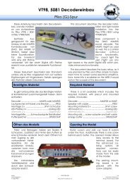
Anzahl der LEDs<br />
Die <strong>Licht</strong>platine kann auf Basis Ihres flexiblen<br />
Schaltungskonzepts mit unterschiedlichen LEDs<br />
bestückt werden. Die Helligkeit der einzelnen<br />
LEDs bleibt dabei unverändert.<br />
Für den Analogbetrieb kann man mit ein bis<br />
zwei gelben LEDs anfangen. Das erlaubt konstante<br />
Beleuchtung ab der geringsten Fahrgeschwindigkeit.<br />
Die Helligkeit bleibt konstant<br />
auch bei höherer Geschwindigkeit.<br />
Bei Digitalbahnen liegt üblicherweise über<br />
20V am Gleis an, hier kann man bis zu 5 weiße<br />
LEDs ohne Probleme bestücken. Für wenig <strong>Licht</strong><br />
kann man sich mit einer LED begnügen. Um die<br />
<strong>Licht</strong>farbe zu beeinflussen kann man LED Farben<br />
gemischt bestücken, die Schaltung beherrscht<br />
auch diese Betriebsform.<br />
Unbenutzte LED Positionen sind durch eine<br />
Drahtbrücke zu schließen.<br />
Pufferkondensator<br />
Auf der Platine sind 2 Positionen für Pufferkondensatoren<br />
vorgesehen. Üblicherweise reicht<br />
ein Kondensator bereits aus. Bei geringer Überscheitung<br />
der LED Spannung kann es notwendig<br />
werden eine höhere Kapazität vorzusehen,<br />
um flackern zu vermeiden.<br />
Number of LEDs<br />
The light boards offers various configuration<br />
possibilities, based on it’s flexible circuit. The<br />
brightness stays constant even with changing<br />
number of LEDs.<br />
For analog operation one or two LEDs allow<br />
constant light even at very slow speeds. It will<br />
stay the same even if the speed it increased.<br />
On digital layouts, track voltage is usually<br />
above 20V. This allows using up to 5 white LEDs<br />
without any problems. If less light is required just<br />
one LED may be used as well. To define the light<br />
color any mixture of yellow and white colored<br />
LEDs may be installed. There are no changes in<br />
the circuit required.<br />
Unused LED positions need to be bridged with<br />
a peace of wire.<br />
Buffer Capacitor<br />
There are 2 positions for capacitors on the<br />
board. On digital layouts one capacitor is good<br />
enough. If track voltage is close to the LED<br />
voltage, a second capacitor may help to<br />
bridge power shortages, i.e. flickering light.<br />
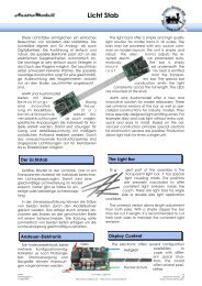
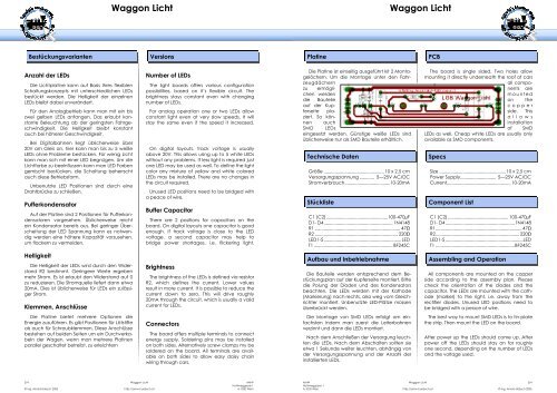
Die Platine ist einseitig ausgeführt kit 2 Montagelöchern.<br />
Um die Montage unter den Fahrzeugdächern<br />
zu ermöglichen<br />
werden<br />
die Bauteile<br />
auf der Kupferseite<br />
plaziert.<br />
So können<br />
auch<br />
SMD LEDs<br />
eingesetzt werden. Günstige weiße LEDs sind<br />
üblicherweise nur als SMD Bauteile erhältlich.<br />
Technische Daten<br />
Größe ................................................. 10 x 2,5 cm<br />
Versorgungsspannung ............ 5—25V AC/DC<br />
Stromverbrauch.....................................10-20mA<br />
Stückliste<br />
C1 (C2)..................................................100-470µF<br />
D1- D4........................................................ 1N4148<br />
R1 ..................................................................... 47Ω<br />
R2 ................................................................... 220Ω<br />
LED1-5...............................................................LED<br />
T1 ................................................................ BF245C<br />
The board is single sided. Two holes allow<br />
mounting it directly underneath the roof of cars<br />
all components<br />
are<br />
mounted<br />
on the<br />
copper<br />
side. This<br />
allows<br />
installation<br />
of SMD<br />
LEDs as well. Cheap white LEDs are usually only<br />
available as SMD components.<br />
Specs<br />
Size ......................................................10 x 2,5 cm<br />
Power Supply............................. 5—25V AC/DC<br />
Current.................................................... 10-20mA<br />
Component List<br />
C1 (C2) ................................................. 100-470µF<br />
D1- D4 ........................................................1N4148<br />
R1...................................................................... 47Ω<br />
R2.................................................................... 220Ω<br />
LED1-5 ...............................................................LED<br />
T1 ................................................................BF245C<br />
Helligkeit<br />
Die Helligkeit der LEDs wird durch den Widerstand<br />
R2 bestimmt. Geringere Werte ergeben<br />
mehr Strom. Es ist erlaubt den Widerstand auf 0<br />
zu reduzieren. Die Stromquelle liefert dann etwa<br />
20mA. Dies ist üblicherweise für LEDs ein zulässiger<br />
Strom.<br />
Klemmen, Anschlüsse<br />
Brightness<br />
The brightness of the LEDs is defined via resistor<br />
R2, which defines the current. Lower values<br />
result in more current. It is possible to reduce the<br />
current down to zero. This will drive roughly<br />
20mA through the circuit, which is usually a valid<br />
current for LEDs.<br />
Aufbau und Inbetriebnahme<br />
Die Bauteile werden entsprechend dem Bestückungsplan<br />
auf der Kupferseite montiert. Bitte<br />
die Polung der Dioden und des Kondensators<br />
beachten. Die LEDs werden mit der Kathode<br />
(Markierung) nach rechts, also weg vom Gleichrichter<br />
montiert. Unbenutzte LED-Plätze müssen<br />
überbrückt werden.<br />
Assembling and Operation<br />
All components are mounted on the copper<br />
side according to the assembly plan. Please<br />
check the orientation of the diodes and the<br />
capacitor. The LEDs are mounted with the cathode<br />
(marker) to the right, i.e. away from the<br />
rectifier diodes. Unused LED positions need to<br />
be bridged with a peace of wire.<br />
Die Platine bietet mehrere Optionen die<br />
Energie zuzuführen. Es gibt Positionen für Lötstifte<br />
als auch für Schraubklemmen. Diese Anschlüsse<br />
bestehen auf beiden Seiten um ein Durchverkabeln<br />
der Wagen, wenn man mehrere Platinen<br />
parallel geschaltet betreibt, zu erleichtern<br />
Connectors<br />
The board offers multiple terminals to connect<br />
energy supply. Soldering pins may be installed<br />
on both sides. Alternatively screw clamps my be<br />
soldered on the board. All terminals are available<br />
on both sides to allow easy daisy chain<br />
wiring through cars.<br />
Die Montage von SMD LEDs erfolgt am einfachsten<br />
indem man zuerst die Leiterbahnen<br />
verzinnt und dann die LEDs montiert.<br />
Nach dem Anschließen der Versorgung leuchten<br />
die LEDs. Nach dem Abschalten sollten sie<br />
etwa 1 Sekunde weiter leuchten, abhängig von<br />
der Versorgungsspannung und der Anzahl der<br />
installierten LEDs.<br />
The best way to mount SMD LEDs is to tin-plate<br />
the strip. Then mount the LED on the board.<br />
After power up the LEDs should come up. After<br />
power off the LEDs should stay on for roughly<br />
one second, depending on the number of LEDs<br />
and the voltage used.<br />
2/4 Waggon <strong>Licht</strong> <strong>AMW</strong><br />
Hohlweggasse 1<br />
© Ing. Arnold Hübsch 2005 http://amw.huebsch.at A-1030 Wien<br />
<strong>AMW</strong> Waggon <strong>Licht</strong> 3/4<br />
Hohlweggasse 1<br />
A-1030 Wien http://amw.huebsch.at © Ing. Arnold Hübsch 2005