
Erfolgreiche ePaper selbst erstellen
Machen Sie aus Ihren PDF Publikationen ein blätterbares Flipbook mit unserer einzigartigen Google optimierten e-Paper Software.
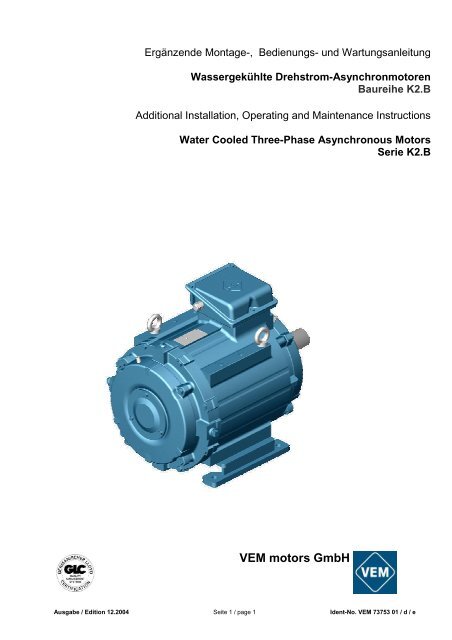
Ergänzende Montage-, Bedienungs- und Wartungsanleitung<br />
Wassergekühlte Drehstrom-Asynchronmotoren<br />
Baureihe K2.B<br />
Additional Installation, Operating and Maintenance Instructions<br />
Water Cooled Three-Phase Asynchronous Motors<br />
Serie K2.B<br />
<strong>VEM</strong> <strong>motors</strong> <strong>GmbH</strong><br />
Ausgabe / Edition 12.2004 Seite 1 / page 1 Ident-No. <strong>VEM</strong> 73753 01 / d / e
1. Konformitätserklärung<br />
Dezember 2004<br />
<strong>VEM</strong> <strong>motors</strong> <strong>GmbH</strong> Werknorm EW-N 1200<br />
Elektromotorenwerk<br />
EG-Konformitätserklärung<br />
Wernigerode Blatt 1 Seite 14<br />
Die elektrischen Betriebsmittel<br />
wassergekühlte asynchrone Drehstrommotoren mit Käfigläufer,<br />
der Reihen<br />
K21B / K23B 225 bis 315<br />
stimmen mit den Vorschriften folgender Europäischer Richtlinien überein:<br />
73/23/EWG<br />
Richtlinie des Rates zur Rechtsangleichung der Rechtsvorschriften der Mitgliedstaaten<br />
betreffend elektrische Betriebsmittel zur Verwendung innerhalb bestimmter Spannungsgrenzen,<br />
geändert durch RL 93/68 /EWG<br />
89/336/EWG<br />
Richtlinie des Rates zur Rechtsangleichung der Rechtsvorschriften der Mitgliedstaaten über<br />
die elektromagnetische Verträglichkeit,<br />
geändert durch RL 91/263/EWG, 92/31/EWG und 93/68/EWG<br />
Die Übereinstimmung mit den Vorschriften dieser Richtlinien wird durch die Einhaltung nachstehender<br />
Normen nachgewiesen:<br />
Europäische Norm / Deutsche Norm<br />
EN 61000-6-1, EN 61000-6-2, EN 61000-6-3, EN 61000-6-4<br />
EN 55014-1, EN 55014-2<br />
EN 61000-3-2, EN 61000-3-3<br />
EN 60034-1, DIN EN 60034-2, EN 60034-5, EN 60034-6, EN 60034-9,<br />
DIN IEC 60038<br />
EN 61800-3 + A11<br />
EN 60204-1<br />
Wernigerode, d. 10.12. 2004<br />
gez. Sander<br />
Geschäftsführer<br />
gez. Beutner<br />
Werkleiter<br />
Diese Erklärung bescheinigt die Übereinstimmung mit den genannten Richtlinien, ist jedoch keine<br />
Zusicherung von Eigenschaften im Sinne der Produkthaftung.<br />
2. Allgemeines<br />
Zur Vermeidung von Schäden an den Motoren und den anzutreibenden Ausrüstungen sind die Bestimmungen<br />
der Bedienungs- und Wartungsanleitung einzuhalten. Insbesondere müssen zur Vermeidung von Gefahren die<br />
Sicherheitshinweise, die gesondert beiliegen, streng beachtet werden. Da die Bedienungs- und Wartungsanleitung<br />
zur besseren Übersichtlichkeit keine einzelnen Informationen für alle denkbaren Sondereinsatzgebiete und<br />
Bereiche mit speziellen Anforderungen enthalten kann, sind bei der Montage durch den Betreiber entsprechende<br />
Schutzvorkehrungen zu treffen.<br />
Diese ergänzende Montage-, Bedienungs- und Wartungsanleitung gilt für wassergekühlte Motoren der Baureihe<br />
K21B / K23B. Neben diesen Hinweisen ist unbedingt die<br />
Montage-, Bedienungs- und Wartungsanleitung Drehstrom-Asynchronmotoren mit Käfigläufer<br />
und mit Schleifringläufer, Normalausführung, <strong>VEM</strong>-Id.-Nr. 68238 01<br />
zu befolgen. Für Sonderausführungen und/oder weitere spezielle Anwendungen werden gegebenenfalls zusätzliche<br />
Montage-, Bedienungs- und Watungshinweise benötigt.<br />
3. Konstruktive Ausführung<br />
Achshöhe Baureihe Werkstoffe für Fußbefestigung<br />
Gehäuse Lagerschilde Füße<br />
225 bis 280 Grauguß mit Stahl angeschraubt<br />
K21B / K23B eingegossenen Grauguß<br />
315<br />
Kühlrohren<br />
Grauguß angegossen<br />
Ausgabe / Edition 12.2004 Seite 2 / page 2 Ident-No. <strong>VEM</strong> 73753 01 / d / e
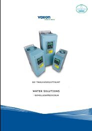
Das Motorgehäuse ist mit eingegossenen Kühlrohren ausgeführt. Die Kühlwasserführung erfolgt über einen<br />
Leitring, der werksseitig montiert ist und an dem die Befestigung des N-seitigen Lagerschildes erfolgt.<br />
Bild 1. Kühlrohranordnung bei Motoren<br />
der Baugrößen 225 bis 280<br />
Die Ausführung gestattet eine optimale Kühlwasserführung mit hohen Wassergeschwindigkeiten und gleichmäßiger<br />
Kühlung.<br />
Anschlusskästen, Lagerschilde, Isolation der Wicklung, Schutzart und Farbgebung entsprechen der Serienausführung.<br />
4. Wasserkühlung<br />
Bei Motoren der Baureihe K21B / K23B wird die im Motor entstehende Verlustwärme über das Kühlwasser abgeführt.<br />
Kühlwasserein- und -austritt befinden sich auf der Nichtantriebsseite (NS). Dem Kühlwasser ist immer<br />
ein Korrosionshemmer, bei Gefahr des Überschreitens der Frostgrenze zusätzlich ein Frostschutzmittel bzw. ein<br />
kombiniertes Mittel zuzufügen.<br />
Die Motoren sind für den Betrieb mit geschlossenen Kreisläufen vorgesehen.<br />
Ein Betrieb in offenen Kreisläufen ist ab Baugröße 315 als Sonderausführung möglich. Falls ein offenes System<br />
benutzt werden soll, ist in jedem Fall eine Rückfrage bei <strong>VEM</strong> <strong>motors</strong> <strong>GmbH</strong> erforderlich.<br />
5. Handhabung<br />
Wenn die Möglichkeit besteht, dass die Motoren bei Temperaturen unterhalb der Frostgrenze gelagert oder<br />
betrieben werden, muss ein Gefrieren des Kühlwassers im Motorinneren verhindert werden. Hierzu kann bei<br />
Lagerung das Kühlwasser entleert werden, bzw. für den Betrieb ist ein Frostschutzadditiv zu verwenden. Es<br />
sind folgende Möglichkeiten zu beachten:<br />
Variante 1 - dauerhaften Betrieb mit Kühlerschutzmittel<br />
Bei Betrieb mit einem Kühlerschutzmittel mit Korrosionsschutzzusatz z. B. HAERTOL Frostox PSF 12/DI oder<br />
ähnlichem ist ein dauerhafter Schutz gegen Korrosion und Frost gegeben.<br />
Variante 2 - Betrieb mit Wasser als Kühlmittel und unterbrochenem Betrieb<br />
Bei unterbrochenem Motorbetrieb wird ein Entfernen des Kühlwassers empfohlen. Vor dem Entleeren ist der<br />
Kühler durch Zugabe z. B. von HAERTOL Frostox PSF 12/DI oder gleichwertigen Produkten zum Kühlwasser<br />
zu schützen. Der Kühlmantel ist dann für ca. 3 Monate gegen Korrosion geschützt.<br />
Variante 3 - nach langandauerndem Stillstand (mit oder ohne Kühlmittel im Kühler)<br />
Nach langandauerndem Stillstand ist vor der Inbetriebnahme ein ungehinderter Kühlwasserlauf zu sichern. E-<br />
ventuelle rostige Stellen sind mit einer ca. 10%-tigen Oxalsäure wie folgt abzubeizen.<br />
• Kühler leeren, falls noch Wasser im Kühler<br />
• Kühler mit 10%-tiger Oxalsäure füllen (ca. 100g/Liter) und ca. 15 min einwirken lassen<br />
• Kühler leeren und mit Wasser spülen – bei Bedarf wiederholen<br />
Falls der Motor längere Zeit außer Betrieb und ohne Wasser war, ist sicher zu stellen, dass das Wasser bei<br />
Inbetriebnahme ungehindert zirkulieren kann, bevor der Motor wieder in Betrieb genommen wird.<br />
6. Wasserzufuhr zum Motor, Anforderungen an Kühlwasser<br />
Das Kühlwasser muss Trinkwasserqualität haben. Der maximale Wasserdruck beträgt 3,5 bar, und die höchstzulässige<br />
Kühlwassereingangstemperatur liegt bei 35 °C. Nachfolgende Mindestanforderungen an das Kühls ystem<br />
sind zu beachten<br />
Ausgabe / Edition 12.2004 Seite 3 / page 3 Ident-No. <strong>VEM</strong> 73753 01 / d / e
Motortyp<br />
K21B / K23B<br />
Kühlwasser-Durchflussmenge<br />
[l/min]<br />
Mindestwasserdruck<br />
[bar]<br />
225 10 0,5 6<br />
250 16 0,7 7<br />
280 18 1,0 9<br />
315 20 1,5 12<br />
Kühlwasser-Temperaturanstieg<br />
[°C]<br />
Auf der Nichtantriebsseite der Motoren (N-Seite) befinden sich rechts und links zwei Gewindebohrungen ¾’’<br />
(siehe Bild 2). Sie sind wahlweise als Zu- oder Ablauf nutzbar. Verbinden Sie die eine Seite mit dem Wasserzulauf<br />
und die gegenüberliegende mit dem Wasserablauf. An den Verbindungsstellen sind geeignete Dichtmittel<br />
zu verwenden.<br />
Die Wasserversorgung muss während des Betriebs des Motors ständig gewährleistet sein.<br />
Ein Betrieb ohne Kühlwasser ist unzulässig.<br />
Auf der N-Seite befinden sich weiterhin oben ein Entlüftungsstopfen 3/8’’ und an der tiefsten Stelle ein Wasserablaufstopfen<br />
3/8’’. Beim Befüllen des Kühlkreislaufs ist der Entlüftungsstutzen zu öffnen. Der Motor ist mit<br />
Kühlwasser zu befüllen, bis Wasser aus der Entlüftungsöffnung austritt. Dabei sorgfältig vorgehen, damit keine<br />
Luft im Kühlkreislauf verbleibt. Danach ist die Entlüftungsöffnung zu verschließen. Dabei ist wiederum ein geeignetes<br />
Dichtmittel zu verwenden. Dichtung der Verbindungen prüfen.<br />
Zum Entleeren des Motors sind Entlüftungs- und Wasserablaufstopfen zu entfernen. Nach dem Entleeren die<br />
Stopfen wieder einschrauben. Bei erneuter Befüllung Dichtheit der Stopfen prüfen.<br />
Bild 2: Be- und Entwässerungsöffnungen<br />
7. Schutzart<br />
Die Normalausführung der Motoren entspricht der Schutzart IP 55, die je nach Bestellung auf IP 56 erhöht werden<br />
kann. Schutzarten IP 65 und höher sind auf Anfrage möglich.<br />
Bei allen Motoren in Bauformen mit dem Wellenende nach oben (IM V3/IM V36) muss seitens des Anwenders<br />
das Eindringen von Wasser entlang der Welle verhindert werden<br />
Bei Flanschmotoren in Bauform IM V3 / IM V36 wird das Ansammeln von Flüssigkeit im Flanschteller durch ein<br />
serienmäßiges Abflussloch vermieden.<br />
Für eine Aufstellung im Freien sind im Normalfall keine besonderen zusätzlichen Schutzmaßnahmen gegen<br />
Witterungseinflüsse erforderlich. Wenn die Möglichkeit besteht, dass die Motoren bei Temperaturen unterhalb<br />
der Frostgrenze gelagert oder betrieben werden, muss ein Gefrieren des Kühlwassers im Motorinneren verhindert<br />
werden. Die Motoren müssen aber auch vor intensiver Sonneneinstrahlung, z.B. durch ein Schutzdach<br />
geschützt werden.<br />
8. Kondenswasserablauf<br />
Alle Motoren haben auf der Antriebs- und Nichtantriebsseite Kondenswasserablaufschrauben, die im Auslieferzustand<br />
verschlossen sind. Bei Inbetriebnahme der Motoren sind die Kondenswasserabläufe zu öffnen. Die<br />
Öffnungen müssen zwingend nach unten gerichtet sein, da es sonst zu gefährlichen Schwitzwasseransammlungen<br />
im Motor kommen kann.<br />
Ausgabe / Edition 12.2004 Seite 4 / page 4 Ident-No. <strong>VEM</strong> 73753 01 / d / e
1. Declaration of Conformity<br />
December 2004<br />
<strong>VEM</strong> <strong>motors</strong> <strong>GmbH</strong> Factory Standard EW-N 1200<br />
Elektromotorenwerk<br />
EC Declaration of Conformity<br />
Wernigerode Sheet 1 Page 14<br />
The electrical apparatus<br />
Water cooled three-phase asynchronous <strong>motors</strong> with squirrel-cage rotor,<br />
of series<br />
K21B / K23B 225 up to 315<br />
are in conformity with the instructions of the following EU Directives:<br />
73/23/EWG<br />
Low Voltage Directive<br />
amended by Directive 93/68 /EWG<br />
89/336/EWG<br />
Directive about Electromagnetic Compatibility<br />
amended by Directives 91/263/EWG, 92/31/EWG und 93/68/EWG<br />
The conformity with the instructions of these Directives is proved by the observations of following standards:<br />
European Standard / German Standard<br />
EN 61000-6-1, EN 61000-6-2, EN 61000-6-3, EN 61000-6-4<br />
EN 55014-1, EN 55014-2<br />
EN 61000-3-2, EN 61000-3-3<br />
EN 60034-1, DIN EN 60034-2, EN 60034-5, EN 60034-6, EN 60034-9,<br />
DIN IEC 60038<br />
EN 61800-3 + A11<br />
EN 60204-1<br />
Wernigerode, 10th of December 2004<br />
Sander<br />
Managing Director<br />
Beutner<br />
Factory Manager<br />
This certificate attests the conformity with the named Directives, however, it is not a promise of properties in<br />
the meaning of product liability.<br />
1. General<br />
To prevent damage to <strong>motors</strong> and the driven equipment the procedures laid down in the Operating and Maintenance<br />
Instructions must be followed. Especially to avoid risk of injury, the separately enclosed Safety Regulations<br />
must be adhered to strictly.<br />
Since for reasons of clarity the Operating and Maintenance Instructions cannot contain specific information with<br />
regard to all conceivable special applications and areas with special requirements, the user himself has to make<br />
appropriate protection arrangements during the installation process. This additional Installation, Operating and<br />
Maintenance Instructions is effective for water-cooled <strong>motors</strong> of series K21B / K23B. Besides this information,<br />
the<br />
Installation, Operation and Maintenance Instruction for Three-Phase Asynchronous Motors with<br />
Squirrel Cage and Slip Ring Rotor, Standard Version, <strong>VEM</strong> ID.-No. 68238 01<br />
must be followed. For special versions and / or other specific applications, additional instructions for installation,<br />
operation and maintenance could be needed.<br />
3. Design Features<br />
Shaft height Series Material for Foot fixing principle<br />
housing end shields feet<br />
225 up to 280 Grey cast iron with Steel Bolted-on<br />
315 K21B / K23B cast-in cooling tubes Grey cast iron Grey cast iron Cast-on<br />
Ausgabe / Edition 12.2004 Seite 5 / page 5 Ident-No. <strong>VEM</strong> 73753 01 / d / e
The motor housing has cast-in cooling tubes. The cooling water passes a guiding ring, that ring is fully assembled<br />
in the factory. On this guiding ring, the N-side end shield is mounted.<br />
Figure 1. Configuration of the cooling<br />
tubes for <strong>motors</strong> in sizes 225 up to<br />
280<br />
The design allows an optimised distribution of the cooling water, with high water velocities and uniform cooling.<br />
Terminal boxes, end shields, winding insulation, degree of protection and painting systems correspond to the<br />
standard version.<br />
3. Water cooling<br />
For <strong>motors</strong> of series K21B / K23B, the waste heat arising from the motor operation is dissipated by the cooling<br />
water. The inlet and outlet for the cooling water is implemented at the non-driving end (N-end). The cooling water<br />
must always contain a rust preventive agent, if the frost line could be crossed, also an anti-freeze or an combined<br />
agent must be added.<br />
The <strong>motors</strong> are intended for operation in closed cycle systems.<br />
Starting from size 315, the operation in open cycle systems is practicable as a special version. If an open cycle<br />
system should be used, special request at <strong>VEM</strong> <strong>motors</strong> <strong>GmbH</strong> is always required.<br />
4. Motor handling<br />
If there is a possibility that the <strong>motors</strong> are stored or operated below the frost line, the freezing of the cooling<br />
water inside the motor must be prevented. For that purpose, during storage, the cooling water can be drained<br />
off, or to the cooling water must be added an anti-freeze, respectively. The following different steps could be<br />
followed:<br />
Version 1 - continuous operation with anti-freeze<br />
If the motor is operated continuously with an anti-freeze and anti-corrosion protective medium, e.g. HAERTOL<br />
Frostox PSF 12/DI or a similar additive, then a continuous protection against corrosion and freezing is given.<br />
Version 2 – interrupted duty and water as an cooling medium<br />
For interrupted motor operation, it is recommended to drain the cooling water off. Before the cooling water is to<br />
be drained off, for protection of the cooling system, an anti-freeze, e.g. HAERTOL Frostox PSF 12/DI or similar<br />
products must be added. By this procedure, the cooling jacket is, for about three months, protected against corrosion.<br />
Version 3 – after long-term standstill (with or without anti-freeze in the cooling system)<br />
After long-term standstill and before putting into operation, it must be checked that there are no obstacles to the<br />
free flow of cooling water. Eventually existing tracks of rust must, by the following procedure, be pickled off by a<br />
10 % oxalic acid.<br />
• Empty the cooling system, if there are any remainders of water inside<br />
• Fill the cooling system by 10 % oxalic acid (about 100 g per litre) and leave it inside for about 15 minutes.<br />
• Empty the cooling system, rinse it by fresh water – repeat this, if necessary<br />
If the motor was in standstill for a long period, and if the water cooling system was empty during this time, before<br />
putting into operation again, it must be checked that the cooling water is able to circulate without any restrictions.<br />
Ausgabe / Edition 12.2004 Seite 6 / page 6 Ident-No. <strong>VEM</strong> 73753 01 / d / e
5. Water feeding, technical requirements for the cooling water<br />
The cooling water must have the quality of drinking water. The maximum water pressure is 3,5 bar, and the<br />
maximum temperature of the entering water must not exceed 35 °C. The following minimum requirements fo r<br />
the cooling system have to be observed.<br />
Motor type<br />
K21B / K23B<br />
Rate of water flow<br />
[l/min]<br />
Minimum water pressure<br />
[bar]<br />
Temperature rise of the cooling<br />
water<br />
[°C]<br />
225 10 0,5 6<br />
250 16 0,7 7<br />
280 18 1,0 9<br />
315 20 1,5 12<br />
At the N-end of the <strong>motors</strong> (NDE), there are at the right-hand and left-hand sides, two threaded holes with ¾’’<br />
diameter (see Figure 2). They can be used optionally as a water inlet or outlet. Connect one of the holes with<br />
the water inlet, and the opposite hole with the water outlet. Use appropriate sealing compounds at the joining<br />
fittings.<br />
During the operation of the motor, the continuous flow of water must be monitored.<br />
Operation without cooling water is not admissible.<br />
At the N-end of the motor, there is on top an air relief plug with 3/8 ” thread, and at the deepest point a water<br />
relief plug with 3/8 “ thread. When the cooling system is filled, the air relief plug must be opened. The motor has<br />
to be filled with cooling water, until the water exits from the air relief hole. The filling procedure must be done<br />
carefully to make sure that no air remains inside the cooling circuit. Then the air relief hole must be closed.<br />
Again an appropriate sealing compound is to be used. Check that the joints are water-proof.<br />
To empty the motor, take the plugs for air relief and water relief off. After the procedure of water relief, the plugs<br />
must be tightened again. If the cooling system is filled again, check that all plugs are tight.<br />
Figure 2: Openings for water<br />
inlet and outlet<br />
6. Degree of protection<br />
The standard version of the <strong>motors</strong> has an IP 55 degree of protection, according to the order, the degree of<br />
protection could be increased to IP 56. Degrees of protection IP 65 and higher are practicable on request.<br />
For all <strong>motors</strong> in types of mounting with shaft end upwards (IM V3 / IM V36), the user must prevent the ingress<br />
of water along the shaft.<br />
For <strong>motors</strong> with flange end-shields, in types of mounting IM V3 / IM V36, the collection of liquids in the flange<br />
recess is avoided by a standard relief hole.<br />
For applications in the open, normally no specific protection measures against weather influences are required.<br />
If it could not be excluded, that the <strong>motors</strong> are stored or operated below the frost line, freezing of the cooling<br />
water inside the motor must be prevented. Additionally, the <strong>motors</strong> must be protected against intensive sun<br />
radiation, e.g. by a protective roof.<br />
7. Drain holes<br />
All <strong>motors</strong> have drain holes (closed by screws) for draining the condensed water, both at the driving and the<br />
non-driving end. In the as-delivered state, the holes are closed. During putting into operation, the holes must be<br />
opened. The openings must always be located at the deepest point of the motor and must be directed to the<br />
bottom, otherwise dangerous collection of condensed water can be formed inside the motor.<br />
Ausgabe / Edition 12.2004 Seite 7 / page 7 Ident-No. <strong>VEM</strong> 73753 01 / d / e
8. Aufbau der Motoren / Construction of the <strong>motors</strong><br />
Kennzahl<br />
Bezeichnung<br />
Designation<br />
Code No.<br />
1.01 Lagerschild D-Seite End shield Drive-end<br />
1.02 Lagerdeckel, D-Seite, außen Bearing cover, Drive-end, external<br />
1.03 Lagerdeckel, D-Seite, innen Bearing cover, Drive-end, internal<br />
1.04<br />
Tellerfeder / Wellfeder, D-Seite,<br />
nicht bei Rollenlagern<br />
Disc spring / wave washer, Drive-end, not for roller bearings<br />
1.05 Wälzlager D-Seite Antifriction bearing, Drive-end<br />
1.06 V-Ring D-Seite V-type rotary seal, Drive-end<br />
1.07 Flanschlagerschild Flange end shield<br />
1.08 Filzring D-Seite Felt ring, Drive-end<br />
2.00 Flanschring Flange ring<br />
2.01 Lagerschild N-Seite End shield Non-drive end<br />
2.02 Lagerdeckel, N-Seite, außen Bearing cover, Non-drive end, external<br />
2.03 Lagerdeckel, N-Seite, innen Bearing cover, Non-drive end, internal<br />
2.04 Wälzlager N-Seite Antifriction bearing, Non-drive end<br />
2.05 V-Ring N-Seite V-type rotary seal, Non-drive end<br />
2.06 Wellfeder N-Seite (oder D-Seite) Wave washer, Non-drive end (or Drive-end)<br />
2.08 Filzring N-Seite Felt ring, Non-drive end<br />
2.09 Entlüftungsstopfen 3/8 “ Air relief plug 3/8 “<br />
2.10 Wasserablassstopfen 3/8 “ Water relief plug 3/8 “<br />
2.11 Verschlussstopfen ¾’’ Blind plug ¾ “<br />
2.12 Dichtringe 2 x Sealing rings 2 pcs.<br />
3.01 1 Paar Motorfüße 1 pair of motor feet<br />
3.06 Ringschraube Lifting eye bolt<br />
4.01 Klemmenkastendeckel Terminal box cover<br />
4.03 Dichtung Klemmenkastendeckel Terminal box cover gasket<br />
4.05 Klemmenkastenunterteil Terminal box base<br />
4.07 Dichtung Klemmenkastenunterteil Terminal box base gasket<br />
4.08 Klemmenplatte Terminal plate<br />
4.09 Kabeleinführung Cable gland<br />
4.10 Verschlussschraube Screw plug for gland opening<br />
4.11 Kabeleinführung für thermischen Wicklungsschutz<br />
Cable gland for thermal winding protection<br />
4.12 Anschluss für therm. Wicklungsschutz Terminal for thermal winding protection<br />
4.17 Normalienbeutel Standard parts bag<br />
5.01 Läufer, komplett Rotor, complete<br />
6.01 Schleuderscheibe, D-Seite Grease thrower ring, Drive-end<br />
6.02 Schleuderscheibe, N-Seite Grease thrower ring, Non-drive end<br />
6.03 Labyrinthbuchse, D- u. N-Seite Labyrinth gland, Drive- and Non-drive end<br />
6.04 Leitscheibe, D-Seite Guide disc, Drive-end<br />
6.05 Leitscheibe, N-Seite Guide disc, Non-drive end<br />
Ausgabe / Edition 12.2004 Seite 8 / page 8 Ident-No. <strong>VEM</strong> 73753 01 / d / e
Wassergekühlter Drehstrom-Asynchronmotor / Grundausführung K2.B<br />
(Beispiel, gelieferte Ausführung kann in Details abweichen)<br />
Water cooled three-phase asynchronous motor / basic version K2.B<br />
(example, delivered version may differ in details)<br />
Ausgabe / Edition 12.2004 Seite 9 / page 9 Ident-No. <strong>VEM</strong> 73753 01 / d / e