VW Polo 9N (2/2002 - 6/2009) SEAT Ibiza 6L ... - Anhängerkupplung
VW Polo 9N (2/2002 - 6/2009) SEAT Ibiza 6L ... - Anhängerkupplung
VW Polo 9N (2/2002 - 6/2009) SEAT Ibiza 6L ... - Anhängerkupplung

Erfolgreiche ePaper selbst erstellen
Machen Sie aus Ihren PDF Publikationen ein blätterbares Flipbook mit unserer einzigartigen Google optimierten e-Paper Software.
© 23.4.2010<br />
1<br />
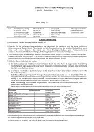
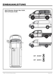
<strong>VW</strong> <strong>Polo</strong> 6R (5/<strong>2009</strong> �)<br />
<strong>VW</strong> <strong>Polo</strong> <strong>9N</strong> (2/<strong>2002</strong> - 6/<strong>2009</strong>)<br />
<strong>SEAT</strong> <strong>Ibiza</strong> <strong>6L</strong> (12/2001 - 2008)<br />
Návod k obsluze a montáţi<br />
Betriebs und Montageanleitung<br />
Owner’s and fitting Manual<br />
TMB PS 067<br />
SPOJOVACÍ - TAŢNÉ ZAŘÍZENÍ<br />
s odnímatelným taţným ramenem<br />
ANHÄNGERKUPPLUNG<br />
mit demontierbarem Zugarm<br />
TRAILER COUPLING<br />
Cars with Removable Towbar<br />
e8 * 94/20 * 0098
7<br />
TAŢNÉ ZAŘÍZENÍ C<br />
Tažné zařízení, typové označení TMB PS 067, je určeno pro připojení přívěsů o<br />
celkové hmotnosti do 1 400 kg za osobní automobily <strong>VW</strong> <strong>Polo</strong> 6R, <strong>VW</strong> <strong>Polo</strong> <strong>9N</strong> a<br />
<strong>SEAT</strong> <strong>Ibiza</strong> <strong>6L</strong>.<br />
Technické parametry<br />
Tažné zařízení je konstruováno pro připojení:<br />
brzděného přívěsu do maximální hmotnosti 1 400 kg<br />
(platí údaj v technickém průkazu vozu)<br />
nebrzděného přívěsu do max. hmotnosti 580 kg<br />
(platí údaj v technickém průkazu vozu)<br />
Konstrukce tažného zařízení odpovídá všem českým i mezinárodním předpisům.<br />
Zařízení prošlo pevnostními zkouškami dle evropské směrnice ES 94/20.<br />
Konstrukce upínacího mechanizmu tažného ramena je chráněna osvědčením o<br />
zápise užitného vzoru č. 15848.<br />
Taţné zařízení je vyrobeno podle schválené dokumentace a odpovídá<br />
homologaci e8* 94/20* 0098.<br />
Průměr kulového čepu 50 mm<br />
Max. svislé statické zatížení na kulový čep 75 kg<br />
Dc - Wert (vztažná síla) 7,53 kN<br />
D C<br />
T �C<br />
� g �<br />
T � C<br />
g - tíhové zrychlení (g = 9,81 ms-2)<br />
T - max. hmotnost tažného vozidla [t]<br />
C - max. hmotnost přívěsu [t]<br />
Celková hmotnost tažného zařízení 15,6 kg<br />
Rozměry 1005 x 584 x 247 mm
Montáţ taţného ramena<br />
Tažné rameno vyjměte z boxu na nářadí v zavazadlovém prostoru.<br />
8<br />
- 1 -<br />
- Vyjměte krytku (4) z otvoru upínacího pouzdra na nosníku tažného zařízení<br />
zatažením směrem dolů a současně k sobě -šipka- a uložte ji na vhodné místo.<br />
Před vloţením taţného ramena vţdy zajistěte, aby nebylo upínací pouzdro<br />
znečištěno. Nečistoty v upínacím pouzdru musí být před pouţitím<br />
bezpodmínečně odstraněny, protoţe brání bezpečnému zajištění taţného<br />
ramena! (Proto po vyjmutí tažného ramena vložte vždy ochrannou zátku zpět do<br />
upínacího pouzdra.)<br />
- 2 -<br />
- Zkontrolujte, je-li taţné rameno v pohotovostní poloze.<br />
- Tzn. zajišťovací kolík ovladací páčky je zasunutý (je viditelná pouze jeho vrchní<br />
červená část) a klíček je v odemknuté poloze (je viditelná jeho červená značka) -<br />
detail šipky-. Klíček nelze vytáhnout ze zámku. (Tažné rameno je tak připraveno<br />
k nasazení do upínacího pouzdra.)<br />
- 3 -<br />
- Není-li taţné rameno z nějakého důvodu v pohotovostní poloze postupujte<br />
následujícím způsobem:<br />
- odemkněte zámek ovladací páčky otočením klíčku o 180° doleva. Levou rukou<br />
uchopte tažné rameno pod kulovým čepem dle obrázku. Prsty pravé ruky<br />
zamáčkněte zajišťovací kolík až na doraz a zároveň pravou rukou stlačte dolů na<br />
doraz ovladací páčku. Ovladací páčka zůstane v této poloze zaaretována a tažné<br />
rameno je připraveno k použití.<br />
- 4 -<br />
- Nasuňte tažné rameno (2) do upínacího pouzdra nosníku tažného zařízení až do<br />
horní polohy upnutí.<br />
- Toto upnutí je provázeno zvukem (zaskočením upínacích kuliček do pouzdra),<br />
otočením ovladací páčky nahoru a vysunutím zajišťovacího kolíku (je viditelná<br />
jeho zelená část) -detail šipka-.<br />
- Sejměte krytku (5) z kulového čepu -šipka-.<br />
- 5 -<br />
- Otočením klíčku (3) o 180° vpravo uzamkněte zámek ovladací páčky (je<br />
viditelná jeho zelená značka) a klíček vyjměte.<br />
Zkontrolujte, je-li taţné rameno správně namontováno.<br />
Rukou (silným zacloumáním) vyzkoušejte jeho upevnění.
9<br />
- 6 -<br />
- Na zámek tažného ramena nasaďte krytku. Ujistěte se, ţe je krytka dobře<br />
nasazena.<br />
Upozornění<br />
- Pokud není taţné rameno v pohotovostní poloze, nelze jej upnout do<br />
upínacího pouzdra nosníku taţného zařízení.<br />
- Při upínání taţného ramena mějte ruce mimo dráhu ovladací páčky. Při<br />
zpětném pohybu páčky do upínací polohy můţe dojít ke zranění prstů!<br />
- V případě, ţe není taţné rameno správně upnuté v upínacím pouzdře (tzn.<br />
ovl. páčka není v upínací poloze a není tedy zcela vysunutý zajišťovací kolík,<br />
nebo nelze uzamknout zámek), nesnaţte se silou dotáhnout ovládací páčku do<br />
své upínací polohy! Opětovně vyjměte taţné rameno, překontrolujte čistotu<br />
klínových ploch (jak taţného ramena, tak upínacího pouzdra) a potom taţné<br />
rameno znovu upněte v upínacím pouzdře.<br />
- Po nasazení taţného ramena vţdy uzamkněte zámek a klíček vyjměte. Taţné<br />
rameno nesmí být v provozu s klíčkem v zámku.<br />
- V pohotovostní poloze nelze z bezpečnostních důvodů vyjmout klíček ze<br />
zámku ovládací páčky.<br />
- Při ztrátě klíčku se obraťte na nejbliţší autorizovaný servis nebo přímo na<br />
výrobce.<br />
Demontáţ taţného ramena<br />
Demontáž tažného ramena proveďte opačným postupem dle následujících pokynů.<br />
- 7 -<br />
- Sejměte ochrannou krytku zámku tažného ramena a otočením klíčku (3) o 180°<br />
vlevo odemkněte zámek ovladací páčky (je viditelná jeho červená značka).<br />
- 8 -<br />
- Nasaďte krytku (5) na kulový čep.<br />
- Tažné rameno uchopte zespodu levou rukou. Prsty pravé ruky zamáčkněte<br />
zajišťovací kolík až na doraz a zároveň pravou rukou stlačte dolů na doraz ovladací<br />
páčku.<br />
- V této poloze je tažné rameno uvolněno a volně vypadne do levé ruky dolů.<br />
Zároveň se zajistí v pohotovostní poloze a je tak připraveno k dalšímu nasazení do<br />
upínacího pouzdra.<br />
- Otřete tažné rameno od nečistot a uložte jej do zavazadlového prostoru.<br />
Pozor! Taţné rameno nenechte nikdy leţet volně v zavazadlovém prostoru. Při<br />
náhlém zabrzdění by mohlo ohrozit bezpečnost cestujících a způsobit<br />
poškození zavazadlového prostoru.<br />
Dbejte na to, aby při demontáţi taţného ramena nedošlo k poškození laku<br />
nárazníku.
- 9 -<br />
- Krytku (4) nasaďte do upínacího pouzdra nosníku tažného zařízení.<br />
Upozornění<br />
10<br />
- Taţné rameno ukládejte do zavazadlového prostoru v pohotovostní poloze,<br />
tzn se zasunutým klíčkem v zámku. Pozor, nikdy nepokládejte taţné rameno<br />
na stranu zasunutého klíčku v zámku - nebezpečí poškození (ohnutí popř.<br />
ulomení) klíčku.<br />
- Nezapomeňte nasadit ochrannou krytku do upínacího pouzdra.<br />
- Při manipulaci s taţným ramenem netlačte na ovladací páčku větší silou neţ<br />
600 N (60 kg)!<br />
Provozování a údrţba<br />
- Tažné zařízení vyžaduje minimální údržbu.<br />
- V případě vyjmutého tažného ramena chraňte dutinu upínacího pouzdra krytkou.<br />
- Pozornost věnujte dutině upínacího pouzdra taţného zařízení, kterou v<br />
případě vyjmutého taţného ramena vţdy chraňte plastovou krytkou. Dle<br />
potřeby vyčistěte a ošetřete klínové plochy upínacího pouzdra vhodným<br />
konzervačním přípravkem (např. WD 40).<br />
- Pozor! Horní část dutiny upínacího pouzdra je ošetřena mazacím tukem<br />
AUTOL TOP 2000, proto dbejte na to, aby tento tuk nebyl odstraněn. Upínací<br />
mechanismus taţného ramena je nutné udrţovat v čistotě.<br />
- Kulový čep tažného ramena občas namažte vhodným mazacím tukem.<br />
- Pokud tažné rameno nepoužíváte, demontujte jej a uložte na místo v<br />
zavazadlovém prostoru.<br />
- Při ukládání tažného ramena používejte vždy ochrannou krytku kulového čepu,<br />
zabráníte tím znečištění zavazadlového prostoru.
11<br />
Důleţitá upozornění<br />
- Po ujetí prvních asi 500 km s přívěsem nechte zkontrolovat dotaţení<br />
upínacích šroubů nosníku k podvozku vozidla a případně dotáhnout<br />
předepsaným momentem 70 Nm! Tuto kontrolu Vám doporučujeme provést<br />
v nejbliţším autorizovaném servisu.<br />
- Veškeré změny nebo úpravy taţného zařízení jsou nepřípustné.<br />
- Před kaţdou jízdou s nasazeným taţným ramenem zkontrolujte správné<br />
nasazení taţného ramena a jeho uzamčení k upínacímu pouzdru nosníku<br />
taţného zařízení.<br />
- Taţné zařízení nesmí být provozováno, pokud taţné rameno nelze<br />
uzamknout nebo v uzamčené poloze je moţné ovladací páčkou volně otáčet.<br />
- Taţné zařízení nesmí být provozováno, je-li poškozené nebo je neúplné.<br />
- Taţné rameno nikdy neodjišťujte při připojeném přívěsu.<br />
- Po připojení přívěsu a propojení elektrických obvodů zkontrolujte funkci<br />
světel přívěsu.<br />
- V případě dlouhodobého provozu s nasazeným taţným ramenem je nutné<br />
pro zabezpečení jeho správné funkce upínací mechanizmus dle potřeby<br />
vyčistit a nakonzervovat vhodným přípravkem (např. WD 40 nebo podobným<br />
konzervačním přípravkem) a několikrát otočit zámkem ovladací páčky.<br />
- Při manipulaci s taţným ramenem netlačte na ovladací páčku větší silou neţ<br />
600 N (60 kg)!<br />
Při pouţívání taţného zařízení dodrţujte pokyny uvedené v tomto návodu k<br />
obsluze.<br />
Výrobce na sebe nebere zodpovědnost za škody způsobené chybně<br />
namontovaným taţným ramenem, jeho přetěţováním nebo poškozením při<br />
havárii vozidla.
12<br />
ANHÄNGERKUPPLUNG<br />
Die <strong>Anhängerkupplung</strong> Typ TMB PS 067 ist für das Ankuppeln von Anhängern<br />
mit einer Masse bis 1 400 kg an die Pkw <strong>VW</strong> <strong>Polo</strong> 6R, <strong>VW</strong> <strong>Polo</strong> <strong>9N</strong> und <strong>SEAT</strong> <strong>Ibiza</strong> <strong>6L</strong><br />
bestimmt.<br />
Technische Angaben<br />
Die <strong>Anhängerkupplung</strong> ist konstruiert zum Anschluss:<br />
des gebremsten Anhängers zum Höchstgewicht 1 400 kg<br />
(es gilt die Angabe im Fahrzeugbrief)<br />
des nicht gebremsten Anhängers zum Höchstgewicht 580 kg<br />
(es gilt die Angabe im Fahrzeugbrief)<br />
Die Konstruktion der <strong>Anhängerkupplung</strong> entspricht allen tschechischen sowie<br />
internationalen Vorschriften. Die <strong>Anhängerkupplung</strong> hat die Festigkeitsprüfungen<br />
gemäß europäischer Richtlinie ES 94/20 bestanden. Die Konstruktion des<br />
Aufnahmemechanismus der Kugelstange ist durch das Zeugnis über die Eintragung<br />
des Gebrauchsmusters Nr. 15848 geschützt.<br />
Die <strong>Anhängerkupplung</strong> wurde gemäß genehmigter Dokumentation hergestellt<br />
und entspricht der Homologation e8* 94/20* 0098.<br />
Kugelbolzen-Durchmesser 50 mm<br />
Maximale vertikale statische Last auf den Kugelbolzen 75 kg<br />
Dc - Wert (Bezugskraft) 7,53 kN<br />
D C<br />
T �C<br />
� g �<br />
T � C<br />
g - Fallbeschleunigung (g = 9,81 ms-2)<br />
T – Höchstgewicht des Schleppfahrzeuges [t]<br />
C - Höchstgewicht des Anhängers [t]<br />
Gesamtgewicht der <strong>Anhängerkupplung</strong> 15,6 kg<br />
Maβe 1005 x 584 x 247 mm<br />
DE
Schlepparm einbauen<br />
Nehmen Sie den Schlepparm aus der Werkzeugbox im Kofferraum heraus.<br />
13<br />
- 1 -<br />
- Nehmen Sie die Abdeckung (4) aus der Öffnung der Spannhülse am<br />
<strong>Anhängerkupplung</strong>sträger durch Ziehen nach unten und gleichzeitig zu sich –Pfeil-<br />
ab und verstauen Sie sie auf einen geeigneten Platz.<br />
Vor dem Einsetzen der Kugelstange sicherstellen, dass der Aufnahmeschacht<br />
nicht verschmutzt ist. Verunreinigungen im Aufnahmeschacht müssen vor<br />
dem Gebrauch unbedingt entfernt werden, denn sie verhindern eine sichere<br />
Verriegelung der Kugelstange! (Deshalb nach dem Herausnehmen der<br />
Kugelstange immer den Verschlussstopfen zurück in den Aufnahmeschacht<br />
einsetzen.)<br />
- 2 -<br />
- Prüfen Sie, ob der Schlepparm in Bereitschaftslage steht.<br />
- D. h., der Sicherungsstift des Betätigungshebels ist eingesteckt (nur sein rotes<br />
Oberteil ist sichtbar) und der Schlüssel ist in der entriegelten Lage (seine rote<br />
Markierung ist sichtbar) –Pfeildetail-. Der Schlüssel kann nicht aus dem Schloss<br />
herausgezogen werden. (Die Kugelstange ist zum Einsetzen in den<br />
Aufnahmeschacht bereit.)<br />
- 3 -<br />
- Steht der Schlepparm aus irgendwelchem Grund nicht in Bereitschaftslage,<br />
verfahren Sie folgendermaβen:<br />
- entriegeln Sie das Schloss des Betätigungshebels (durch Linksdrehen des<br />
Schlüssels um 180º).<br />
- fassen Sie den Schlepparm unterhalb des Kugelbolzens mit der Hand wie in der<br />
Abb. gezeigt an. Drücken Sie den Sicherungsstift mit Fingern der rechten Hand bis<br />
zum Anschlag ein und drücken Sie gleichzeitig mit der rechten Hand den<br />
Betätigungshebel bis zum Anschlag nach unten. Der Betätigungshebel bleibt in<br />
dieser Lage arretiert und der Schlepparm ist zum Gebrauch vorbereitet.<br />
- 4 -<br />
- Setzen Sie den Schlepparm (2) in die Spannhülse des <strong>Anhängerkupplung</strong>strägers<br />
bis in die obere Lage der Spannung ein.<br />
- Diese Spannung wird mit einem Ton begleitet (durch Einrasten der<br />
Aufnahmekugeln in die Hülse), durch Drehen des Betätigungshebels nach oben und<br />
Ausschieben des Sicherungsstiftes (sein grünes Teil ist sichtbar) –Detail Pfeil-.<br />
- Nehmen Sie die Abdeckung (5) vom Kugelbolzen -Pfeilab.
14<br />
- 5 -<br />
- Durch Rechtsdrehen des Schlüssels (3) um 180º verriegeln Sie das Schloss des<br />
Betätigungshebels (seine grüne Markierung ist sichtbar) und ziehen Sie den<br />
Schlüssel ab.<br />
Prüfen Sie, ob der Schlepparm richtig eingebaut ist. Prüfen Sie von Hand (durch<br />
kräftiges Herumzerren) seine Befestigung.<br />
- 6 -<br />
- Auf das Kugelstangenschloss die Kappe aufsetzen. Richtigen Sitz der Kappe<br />
beachten.<br />
Hinweis<br />
- Wenn der Schlepparm nicht in Bereitschaftslage steht, kann er nicht in die<br />
Spannhülse des <strong>Anhängerkupplung</strong>strägers eingespannt werden.<br />
- Beim Einsetzen der Kugelstange die Hände außerhalb des Wirkungsbereichs<br />
des Betätigungshebels halten. Bei Rückbewegung des Hebels in die<br />
Einraststellung kann es zu Fingerverletzungen kommen!<br />
- Falls der Schlepparm nicht richtig in der Spannhülse eingespannt ist (d. h.<br />
der Betätigungshebel steht nicht in der Einspannstelle und der Sicherungsstift<br />
ist also nicht völlig herausgeschoben, oder das Schloss geht nicht verriegeln),<br />
bemühen Sie sich nicht den Betätigungshebel in seine Einspannstelle mit<br />
Gewalt festzuziehen! Nehmen Sie den Schlepparm wiederholt heraus,<br />
überprüfen Sie die Sauberkeit der Keilflächen (sowohl vom Schlepparm, als<br />
auch von der Spannhülse) und spannen Sie anschließend den Schlepparm<br />
wiederholt in der Spannhülse ein.<br />
- Nach dem Einsetzen des Schlepparms verschlieβen Sie immer das Schloss<br />
und ziehen Sie den Schlüssel ab. Der Schlepparm darf mit dem Schlüssel im<br />
Schloss nicht im Betrieb sein.<br />
- In Bereitschaftslage kann der Schlüssel aus dem Schloss des<br />
Betätigungshebels nicht abgezogen werden.<br />
- Wenn der Schlüssel verloren geht, wenden Sie sich an den nächsten -Betrieb<br />
oder direkt an den Hersteller.<br />
Schlepparm ausbauen<br />
Den Ausbau des Schlepparms führen Sie in der umgekerten Reihenfolge durch<br />
gemäβ folgenden Hinweisen.<br />
- 7 -<br />
- Schutzkappe für das Kugelstangenschloss abnehmen und das Schloss des<br />
Betätigungshebels durch eine 180°<br />
-Linksdrehung des Schlüssels (3) aufschließen (rote Markierung am Schloss ist<br />
sichtbar).
15<br />
- 8 -<br />
- Setzen Sie die Abdeckung (5) auf den Kugelbolzen auf.<br />
- Fassen Sie den Schlepparm von unten mit der linken Hand an. Drücken Sie den<br />
Sicherungsstift mit Fingern der rechten Hand bis zum Anschlag ein und drücken<br />
Sie gleichzeitig mit der rechten Hand den Betätigungshebel bis zum Anschlag nach<br />
unten.<br />
- In dieser Lage ist der Schlepparm gelöst und fällt frei nach unten in die linke<br />
Hand heraus. Er wird gleichzeitig in der Bereitschaftslage gesichert und ist so zum<br />
nächsten Einsetzen in die Spannhülse vorbereitet.<br />
- Wischen Sie den Schlepparm von Schmutz ab und verstauen Sie den Arm im<br />
Kofferraum.<br />
Achtung! Lassen Sie den Schlepparm niemals frei im Kofferraum liegen. Bei<br />
plötzlichen Bremsmanövern könnte er die Sicherheit der Fahrgäste bedrohen<br />
und den Kofferraum beschädigen.<br />
Achten Sie darauf, dass beim Ausbau des Schlepparmes keine<br />
Lackbeschädigung des Stoßfängers.<br />
- 9 -<br />
- Setzen Sie die Abdeckung (4) in die Spannhülse des <strong>Anhängerkupplung</strong>strägers<br />
ein.<br />
Hinweise<br />
- Verstauen Sie den Schlepparm in Bereitschaftslage im Kofferraum, d. h. mit<br />
im Schloss eingestecktem Schlüssel. Achtung, die Kugelstange niemals mit<br />
eingestecktem Schlüssel auf die Seite legen – Beschädigungsgefahr des<br />
Schlüssels (Biege- bzw. Bruchgefahr).<br />
- Vergessen Sie nicht die Schutzkappe in die Spannhülse einzusetzen.<br />
- Bei Handhabung mit Schlepparm drücken Sie den Betätigungshebel<br />
nicht mit mehr Kraft als 600 N (60 kg).<br />
Betrieb und Wartung<br />
- Die <strong>Anhängerkupplung</strong> erfordert minimale Wartung.<br />
- Wenn sie abgenommen wird, schützen Sie den Hohlraum der Spannhülse mit der<br />
Kappe.<br />
- Beachten Sie den Hohlraum der Spannhülse von Ahängerkupplung. Falls der<br />
Schlepparm abgenommen wird, schützen Sie ihn mit einer Plastkappe.<br />
Säubern Sie und behandeln Sie die Keilflächen der Spannhülse entsprechend<br />
dem Bedarf mit geeignetem Konservierungsmittel (z. B. WD 40).<br />
- Vorsicht! Der Hohlraum-Oberteil der Spannhülse ist mit Schmierfett<br />
AUTOL TOP 2000 behandelt, achten Sie deshalb darauf, dass dieses Fett nicht<br />
entfernt wird. Die Klemmeinrichtung des Schlepparms muss sauber<br />
gehalten werden.
16<br />
- Fetten Sie ab und zu den Kugelbolzen des Schlepparms mit geeignetem<br />
Schmierfett.<br />
- Wenn Sie den Schlepparm nicht benutzen, bauen Sie ihn aus und verstauen Sie<br />
ihn im Kofferraum.<br />
- Verwenden Sie beim Verstauen des Schlepparms immer die Schutzkappe für<br />
Kugelbolzen, Sie vermeiden damit die Verunreinigung des Kofferraums.<br />
Wichtige Hinweise<br />
- Wenn Sie die ersten ca. 500 km mit Anhänger zurückgelegt haben, lassen Sie<br />
das Festziehen der Befestigungsschrauben Träger an Fahrwerk des<br />
Fahrzeuges überprüfen und ggf. mit vorgeschriebenem Anzugsdrehmoment<br />
70 Nm festziehen. Wir empfehlen Ihnen, diese Prüfung im nächsten -Betrieb<br />
durchführen zu lassen.<br />
- Alle Veränderungen bzw. Bearbeitungen an der <strong>Anhängerkupplung</strong> sind<br />
nicht zulässig.<br />
- Überprüfen Sie vor jeder Fahrt mit eingesetzem Schlepparm das<br />
ordnungsgemäβe Einsetzen des Schlepparms und die Verriegelung an<br />
Spannhülse des <strong>Anhängerkupplung</strong>strägers.<br />
- Die <strong>Anhängerkupplung</strong> darf nicht in Betrieb gesetzt werden, wenn der<br />
Schlepparm nicht verriegelt werden kann oder der Betätigungshebel in der<br />
verriegelten Lage sich frei drehen lässt.<br />
- Die <strong>Anhängerkupplung</strong> darf nicht in Betrieb gesetzt werden, wenn sie<br />
beschädigt bzw. nicht komplett ist.<br />
- Entriegeln Sie den Schlepparm niemals bei angekuppeltem Anhänger.<br />
- Wenn der Anhänger angekuppelt und der Schaltkreis verbunden ist, prüfen<br />
Sie die Anhängerleuchten auf Funktion.<br />
- Bei Dauerbetrieb mit eingesetzem Schlepparm muss die Klemmeinrichtung<br />
entsprechend dem Bedarf gereingt und mit geeignetem Konservierungsmittel<br />
(z. B. WD 40 bzw. mit ähnlichem Konservierungsmittel) konserviert und<br />
mehrmals mit dem Schloss des Betätigungshebels gedreht werden, damit die<br />
richtige Funktion gesichert ist.<br />
- Bei Handhabung mit Schlepparm drücken Sie den Betätigungshebel nicht<br />
mit mehr Kraft als 600 N (60 kg).<br />
Bei Verwendung der <strong>Anhängerkupplung</strong> beachten Sie die in dieser<br />
Betriebsanleitung angeführten Hinweise.<br />
Der Hersteller übernimmt keine Verantwortung für Schäden verursacht<br />
durch falsch eingebauten Schlepparm, Überlastung oder Beschädigung bei<br />
Vekehrsunfall.<br />
GB
17<br />
TOWING COUPLING<br />
The towing device, type designation TMB PS 067, is designed for coupling of<br />
trailers with the total weight up to 1 400 kg behind the passenger cars <strong>VW</strong> <strong>Polo</strong> 6R,<br />
<strong>VW</strong> <strong>Polo</strong> <strong>9N</strong> and <strong>SEAT</strong> <strong>Ibiza</strong> <strong>6L</strong>.<br />
Technical parameters<br />
The towing coupling has been designed for linking with:<br />
A trailer with brakes, up to maximum weight 1 400 kg<br />
(consult the Technical Certificate of the car)<br />
A trailer without brakes, up to maximum weight 580 kg<br />
(consult the Technical Certificate of the car)<br />
The design of the towing coupling meets all Czech as well as international<br />
regulations. The coupling has passed the strength tests in compliance with the<br />
European Directive EC 94/20. The design of the clamping mechanism of the<br />
towing arm is protected with the certificate of the registration of the Utility Design<br />
No. 15848.<br />
The towing coupling is manufactured according to the approved<br />
documentation, and it complies with the homologation e8* 94/20* 0098.<br />
Diameter of the ball journal 50 mm<br />
Max. vertical static load upon the ball journal 75 kg<br />
Dc - Wert (relative strength) 7,53 kN<br />
D C<br />
T �C<br />
� g �<br />
T � C<br />
g – gravity acceleration (g = 9,81 ms-2)<br />
T – max. weight of the trailing vehicle [t]<br />
C – max. weight of the trailer [t]<br />
The total weight of the towing coupling 15,6 kg<br />
Dimensions 1005 x 584 x 247 mm
Fitting of the towing arm<br />
Take the towing arm out of the tool box in the luggage compartment.<br />
18<br />
- 1 -<br />
- Take the cover (4) out of the hole of the clamping bush on the beam of the towing<br />
coupling pulling it downwards and towards you at the same time -arrow- and<br />
deposit it in a suitable place.<br />
Before inserting the towing arm, always make sure that the collet is not dirty.<br />
Any dirt in the collet must be unconditionally removed prior to use, because it<br />
prevents the safe fastening of the towing arm! (Therefore it is always necessary<br />
to reinsert the protective plug into the collet after removing the towing arm.)<br />
- 2 -<br />
- Check whether the towing arm is in the stand-by position.<br />
- I.e. the safety pin of the control lever is plugged in (its upper red section can be<br />
seen only) and the key is in unlocked position (its red mark is visible) -detail<br />
arrows-. The key cannot be removed from the lock. (It means that the towing arm is<br />
ready for inserting it into the collet.)<br />
- 3 -<br />
- If for some reason the towing arm is not in the stand-by position, proceed in<br />
the following way:<br />
- Unlock the lock of the control lever (turning the key through 180° to the left).<br />
- Grip the towing arm below the ball journal with your left hand according to the<br />
figure. Using the fingers of your right hand, press down the safety pin up to the<br />
stop, and at the same time, press down the control lever up to the stop with your<br />
right hand. The control levers remains arrested in this position, and the towing arm<br />
is ready for use.<br />
- 4 -<br />
- Insert the towing arm (2) into the clamping bush of the beam of the towing<br />
coupling as far as to the upper clamping position.<br />
- The clamping is accompanied by a sound (of the clamping balls being snapped in<br />
the bushing); the control lever turns upwards and the safety pin is plugged out (its<br />
green section is visible) -detail arrow-.<br />
- Remove the cover (5) from the ball journal -arrow-.<br />
- 5 -<br />
- Turning the key (3) through 180° to the right, lock the lock of the control lever<br />
(its green mark is visible) and take the key out.<br />
Check whether the towing arm is fitted properly. Try its fitting by hand<br />
(shaking it vigorously).
- 6 -<br />
- Fit a cap on the lock of the towing arm. Make sure the cap is fitted well.<br />
Advice<br />
19<br />
- If the towing arm is not in the stand-by position, it is not possible to clamp it<br />
into the clamping bush of the beam of the towing coupling.<br />
- When clamping the towing arm, keep your fingers out of the path of the<br />
control lever. During the return movement of the lever to the clamping<br />
position, it could hurt your fingers!<br />
- In case the towing arm is not correctly fixed in the clamping bush (i.e. the<br />
control lever is not in the clamping position, so that the locking peg is not<br />
completely out, or the lock cannot be locked), do not try to pull the control<br />
lever to its clamping position by force! Take the towing arm out, check the<br />
cleanness of the wedge-shaped surfaces (both of the towing arm and of the<br />
clamping bush) and then re-clamp the towing arm in the clamping bush.<br />
- After fitting the towing arm, lock the lock always and take the key out. The<br />
towing arm may not be operated with the key in the lock.<br />
- In the stand-by position , it is not possible to take the key out of the lock of<br />
the control lever, because of safety reasons.<br />
- If you happen to lose the key, please contact the nearest service centre or the<br />
manufacturer directly.<br />
Removing of the towing arm<br />
The towing arm is removed in the reversed way, according to the following<br />
instructions.<br />
- 7 -<br />
- Remove the protecting cap of the towing arm lock, and turning the key (3) by<br />
180° to the left, unlock the lock of the control lever (its red mark can be seen).<br />
- 8 -<br />
- Fit the cover (5) upon the ball journal.<br />
- Grip the towing arm from below with your left hand. Using the fingers of your<br />
right hand, press down the safety pin up to the stop, and at the same time, press<br />
down the control lever up to the stop with your right hand.<br />
- In this position, the towing arm is released, and will fall down to your left hand by<br />
itself. At the same time, it gets locked in the stand-by position and therefore, it is<br />
ready for further clamping into the clamping bush.<br />
- Wipe off dirt from the towing arm, and deposit it into the luggage compartment.<br />
Caution! Never leave the towing arm lying freely in the luggage compartment.<br />
In case of sudden braking, it could threaten the safety of the passengers and<br />
cause damage to the luggage compartment.
20<br />
Be careful to avoid damage to the paint of the bumper when removing the<br />
towing arm.<br />
- 9 -<br />
- Fit the cover (4) into the clamping bush of the beam of the towing coupling.<br />
Advice<br />
- The towing arm is to be deposited in the luggage compartment in the standby<br />
position, i.e. with the key inserted in the lock. Caution: never lay the towing<br />
arm with the key inserted in the lock downwards – a risk of damaging the key<br />
(it could bend or break).<br />
- Do not forget to fit the protecting cover into the clamping bush.<br />
- When handling the towing arm, do press upon the control lever with more<br />
force than 600 N (60 kg)!<br />
Operation and maintenance<br />
- The towing coupling requires a minimum maintenance.<br />
- When the towing arm has been removed, protect the hollow of the clamping bush<br />
with the cover.<br />
- Pay attention to the cavity of the clamping bush of the towing coupling,<br />
protecting it by the plastic cover in case of a removal of the towing arm. Clean<br />
and treat the wedge-shaped surfaces of the clamping bush as needed by a<br />
suitable preserving agent (e.g. WD 40).<br />
- Warning! The upper part of the clamping bush cavity is treated with the<br />
AUTOL TOP 2000 lubricating grease, therefore take care that this grease is<br />
not removed. The clamping mechanism of the towing arm must be kept clean.<br />
- From time to time, lubricate the ball journal of the towing arm with a suitable<br />
lubricating grease.<br />
- Meanwhile you are not using the towing arm, remove it and put it to its place in<br />
the luggage compartment.<br />
- When storing the towing arm, always use the protecting cover of the ball journal,<br />
in order to avoid soiling of the luggage boot.
Important advice<br />
21<br />
- After having driven about the first 500 km with the trailer, it is necessary to<br />
check the tightening of the screws clamping the beam to the chassis of the<br />
vehicle, and if necessary, to tighten them with the prescribed torque 70 Nm!<br />
We recommend you to have it checked in the nearest service centre.<br />
- Any changes or alterations of the towing coupling are not admissible.<br />
- Before every drive with the towing arm fitted, check the proper fitting of the<br />
towing arm and its locking to the clamping bush of the beam of the towing<br />
coupling.<br />
- The towing coupling must not be operated if the towing arm cannot be<br />
locked, or it is possible to turn the control lever freely in the locked position.<br />
- The towing coupling must not be operated if it is damaged or not complete.<br />
- Never unlock the towing arm with a linked trailer.<br />
- After linking the trailer and interconnecting the electric circuits, check the<br />
function of the lights of the trailer.<br />
- In case of a long-time operation with the towing arm fitted, in order to<br />
provide for the proper functioning of the clamping mechanism it is necessary<br />
to clean it as needed, and to apply a suitable preservation agent (e.g. WD 40 or<br />
a similar preserving agent) and to turn the lock of the control lever several<br />
times.<br />
- When handling the towing arm, do not press upon the control lever with<br />
more force than 600 N (60 kg)!<br />
Observe the instructions stated in this instruction manual at using the towing<br />
coupling.<br />
The manufacturer does not assume responsibility for any damages resulting<br />
from improper fitting of the towing arm, its overloading or damage due to the<br />
car accidents.
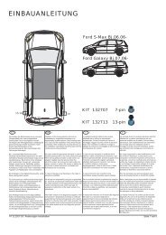
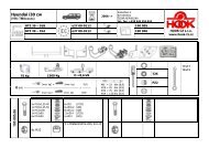
Postup montáţe: Montageainleitung: Fitting instruction:<br />
22<br />
Seznam dílů taţného zařízení:<br />
Verzeichnis der Teile der <strong>Anhängerkupplung</strong>:<br />
List of components:<br />
Název dílu Kusů Pozice<br />
Bezeichnung des Teils, Name of the part Stück, Quantity Position, Positon<br />
Nosník úplný (s držákem zásuvky a identifikačním štítkem)<br />
Träger vollständig (mit Steckdosenhalter und Identifikationsschild)<br />
Beam assembly (with plug box holder and ID plate) 1 1<br />
Tažné rameno (Kugelhals, Towarm) 1 2<br />
Klíč k zámku ovladací páčky (Schlüssel zum Schloss des Bedienhebels, Key to the<br />
lock of the control lever) 2 3<br />
Krytka upínacího pouzdra (Abdeckung der Aufspannhülse, Cover of the clamping<br />
bushing) 1 4<br />
Krytka kul. čepu (Kugelbolzendeckel, Cover of the ball) 1 5<br />
Šroub (Schraube, Bolt) M10 x 30 4 6<br />
Samolepící štítek (Selbstklebeetikette,<br />
Self-adhesive sticker) „75 kg“ 1 -
23<br />
Seznam speciálního nářadí :<br />
Momentový klíč, pila<br />
Montáţ taţného zařízení na vozidlo<br />
- Podle seznamu zkontrolujte jednotlivé součásti tažného zařízení.<br />
- Demontujte nárazník a zadní lampy.<br />
- Pokud je to nezbytné, strhněte záslepky otvorů pro uchycení tažného zařízení a<br />
odstraňte části plastizolu.<br />
- Demontujte výztuhu nárazníku.<br />
- Tažné zařízení (1) nasuňte podélnými nosníky do otvorů na zadním čele vozu a<br />
ustavte jej do správné polohy.<br />
- Nosníky přišroubujte pomocí čtyř šroubů M10 x 30 (6) k podvozku vozu.<br />
- Tažné zařízení zatáhněte směrem dozadu od vozu a šrouby (střídavě) na obou<br />
stranách dotáhněte utahovacím momentem 70 Nm.<br />
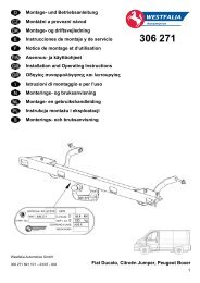
- Vytvoření otvoru do zadního nárazníku:<br />
- Demontovaný zadní nárazník položte na měkkou plstěnou podložku.<br />
- Na vnitřní straně nárazníku naměřte jeho střed a nakreslete rysku.<br />
- Dle obrázku nakreslete a vystřihněte papírovou šablonu.<br />
- Přiložte papírovou šablonu na vnitřní stranu nárazníku podle popisu na šabloně a<br />
obkreslete tvar vystřižení.<br />
- Podle vzniklé rysky vyřízněte vhodným nástrojem otvor pro tažné rameno a držák<br />
zásuvky (pozor na poškození laku nárazníku). Otvor začistěte.<br />
- Pokračujte montáží elektrické instalace tažného zatížení na vozidlo.<br />
- Po skončení montáže elektrické instalace namontujte zpět všechny demontované<br />
díly a příslušné spoje utáhněte předepsanými utahovacími momenty.<br />
- Na zadní nárazník nad výřez pro tažné rameno nalepte samolepící štítek „75 kg“<br />
(příslušné místo před nalepením očistěte a odmastěte).
24<br />
Verzeichnis Spezialwerkzeug:<br />
Drehmomentschlüssel, Säge<br />
Montage der <strong>Anhängerkupplung</strong> auf das Fahrzeug<br />
- Überprüfen Sie Die Befestigungsteile auf Vollständigkeit.<br />
- Demontieren Sie den Stoßfänger und die Rücklichter.<br />
- Im Bereich Reißen Sie die Verblendungen der Öffnungen für die Befestigung der<br />
<strong>Anhängerkupplung</strong> und Entfernen Sie im Bedarfsfall Plastisolteile.<br />
- Demontieren Sie den Innenstoßfänger.<br />
- Setzen Sie die <strong>Anhängerkupplung</strong> (1) durch die Längsträger in die Öffnungen am<br />
hinteren Fahrzeugstirn ein und richten Sie sie in die richtige Lage ein.<br />
- Schrauben Sie die Träger mit vier Schrauben M10 x 30 (6) an das Fahrwerk des<br />
Fahrzeugs an.<br />
- Ziehen Sie die <strong>Anhängerkupplung</strong> nach hinten vom Fahrzeug und schrauben Sie<br />
die Schrauben (abwechselnd) auf beiden Seiten mit Anzugsdrehmoment 70<br />
Nm.<br />
- Ausschneiden der Öffnung in den Heckstoßfänger<br />
- Der demontierte Heckstoßfänger ist auf eine weiche Filzunterlage zu legen.<br />
- Messen Sie auf der Innenseite des Stoßfängers seine Mitte aus und zeichnen Sie<br />
eine Strichmarke ein.<br />
- Zeichnen und Schnitten Sie die Papierschablone laut der Anleitung.<br />
- Legen Sie die Papierschablone auf die Innenseite des Stoßfängers laut der<br />
Beschreibung auf der Schablone und zeichnen Sie die Ausschnittform ab.<br />
- Schneiden Sie mit einem geeigneten Werkzeug eine Öffnung für den Deichselarm<br />
und den Steckdosenhalter nach der entstandenen Strichmarke aus. (Achtung auf<br />
Lackbeschädigungen des Stoßfängers) Die Öffnung ist zu säubern.<br />
- Setzen Sie die Montage der Elektroinstallation der Zugbelastung auf das Fahrzeug<br />
fort.<br />
- Bauen Sie nach Beendung der Montage der Elektroinstallation alle demontierten<br />
Teile wieder auf und ziehen Sie sie mit den vorgeschriebenen Anziehmomenten<br />
nach.<br />
- Kleben Sie auf den Heckstoßfänger über dem Kugelhals das Selbstklebeetickett<br />
“75 kg” (die zuständige Stelle ist vor dem Aufkleben zu reinigen und zu entfetten).
25<br />
List of special tools and gadgets:<br />
Torque wrench, Cutter<br />
Mounting the equipment onto the vehicle<br />
- Check contents of the towbar package against the part list.<br />
- Dismount rear bumper and rear lights.<br />
- If necessary, take out the blinds from the pre-bored holes in the sills and clean the<br />
interior of the holes from the deposits of plastic protection.<br />
- Dismount the inside bumper.<br />
- Fit the towing coupling (1) by its longitudinal beams into the holes at the rear<br />
nose of the car and set it to the correct position.<br />
- By means of four screws M10 x 35 (6) fasten the beams to the chassis of the<br />
vehicle.<br />
- Pull the towing coupling backwards from the vehicle and tighten the screws<br />
(alternately) on both sides with the tightening torque of 70 Nm.<br />
- Cutting an opening in the back bumper:<br />
- Dismounted back bumper is placed on a soft pad .<br />
- Measure and score the center of the bumper on the bottom side.<br />
- Draw (on the paper) the template according to picture enclosed in the manual and<br />
cut out it.<br />
- Place the paper template on the internal side of the bumper as drawn on the<br />
template and mark the shape.<br />
- Cut out an opening for the towbar and plugbox holder in the bumper by a suitable<br />
tool (beware of scratching the outer surface) and clean the edge of the hole.<br />
- Further step is the installation of electric wiring.<br />
- After installing the cable harness remount back all dismantled parts and tighten<br />
the appropriate joints by the respective torques.<br />
- Put a self-adhesive sticker “75 kg” on the back bumper- above the towarm (clean<br />
and degrease the appropriate place for the sticker).
Záruční list<br />
26<br />
Výrobce tažného zařízení poskytuje záruku na konstrukci, použitý materiál,<br />
výrobní provedení a funkci dodaného tažného zařízení 24 měsíců od data prodeje.<br />
Reklamaci výrobku v zákonné lhůtě uplatní kupující u prodávajícího. Oprávněnost<br />
reklamace posoudí zástupce prodávajícího spolu se zástupcem výrobce v souladu<br />
s platnými předpisy.<br />
Podmínkou platnosti záruky je, aby tažné zařízení bylo používáno pouze k účelům,<br />
ke kterým je určeno.<br />
Kupující je povinen prověřit stav zboží při jeho převzetí. V případě poškození<br />
zboží, nedodání části tažného zařízení apod. je kupující povinen tuto skutečnost<br />
neprodleně ohlásit prodávajícímu a to bez zbytečného odkladu po převzetí zboží.<br />
Všechny součásti a příslušenství tažného zařízení musí být před odbornou montáží,<br />
zkontrolovány ve vztahu k jejich kompaktibilitě na odpovídající typ vozidla. Tažná<br />
zařízení, smí být použita pouze na výrobcem uvedený typ vozidla. V případě<br />
neodborné montáže či montáže tažného zařízení na typ vozidla, pro který není<br />
tažné zařízení určeno, neodpovídá výrobce za případné poškození tažného zařízení,<br />
způsobené vadnou montáží či jeho nesprávným použitím.<br />
Prodávající odpovídá za vady, které mělo tažné zařízení při jeho převzetí<br />
kupujícím.<br />
Záruka se nevztahuje na škody mající původ v běžném opotřebení, v přetěžování<br />
a neodborném používáním tažného zařízení, dále pokud není užíváno v souladu<br />
s pokyny uvednými v návodu k obsluze. Záruka se dále nevztahuje na škody<br />
způsobené živelnými vlivy. Prodávající rovněž neodpovídá za škodu v případě, kdy<br />
bylo tažné zařízení změněno či jinak upraveno.<br />
Záruka zaniká, bylo-li tažné zařízení poškozeno havárií (kromě havárie vyvolané<br />
samotným tažným zařízením) nebo zásahy do jeho mechanismu a konstrukce.
27<br />
Garantieinformationen und Bedingungen<br />
Der Hersteller der <strong>Anhängerkupplung</strong> gewährt auf Konstruktion, verwendetes<br />
Material, Produktionsausführung und Funktion der gelieferten <strong>Anhängerkupplung</strong><br />
eine Garantie von 24 Monaten ab Verkaufsdatum.<br />
Die Reklamation des Produkts in der gesetzlichen Frist macht der Käufer beim<br />
Verkäufer geltend. Die Berechtigung der Reklamation beurteilt ein Vertreter des<br />
Verkäufers zusammen mit einem Vertreter des Herstellers entsprechend der<br />
gültigen Vorschriften.<br />
Bedingung für die Gültigkeit der Garantie ist, dass die <strong>Anhängerkupplung</strong> zum für<br />
sie bestimmten Zweck angewendet wurde.<br />
Der Käufer ist verpflichtet, den Zustand der Ware bei Übernahme zu überprüfen.<br />
Bei Beschädigung der Ware, fehlendem Teil der <strong>Anhängerkupplung</strong>, u.ä. ist der<br />
Käufer verpflichtet, diese Tatsache unverzüglich dem Verkäufer zu melden, dies<br />
ohne unnötigen Verzug nach Warenübernahme.<br />
Alle Teile und das Zubehör der <strong>Anhängerkupplung</strong> muss vor der fachgerechten<br />
Montage in Beziehung zur Kompatibilität für den entsprechenden Fahrzeugtyp<br />
kontrolliert werden. <strong>Anhängerkupplung</strong>en dürfen nur am vom Hersteller<br />
angeführten Fahrzeugtyp benutzt werden. Bei nicht fachgerechter Montage oder<br />
Montage der <strong>Anhängerkupplung</strong> an einen Fahrzeugtyp, für welchen sie nicht<br />
bestimmt ist, haftet der Hersteller nicht für eventuelle Beschädigungen der<br />
<strong>Anhängerkupplung</strong>, verursacht durch fehlerhafte Montage oder falsche Benutzung.<br />
Der Verkäufer haftet für Mängel, welche die <strong>Anhängerkupplung</strong> bei Übernahme<br />
durch den Käufer hatte.<br />
Die Garantie bezieht sich nicht auf Schäden, die ihre Ursache in normalem<br />
Verschleiß, Überlastung und nicht fachgerechter Benutzung der <strong>Anhängerkupplung</strong><br />
haben, weiter wenn sie nicht gemäß der Anweisungen in der Gebrauchsanleitung<br />
benutzt wurde. Die Garantie bezieht sich weiter nicht auf durch Naturkatastrophen<br />
verursachte Schäden. Der Verkäufer haftet ebenfalls nicht für Schaden, wenn die<br />
<strong>Anhängerkupplung</strong> geändert oder angepasst wurde.<br />
Die Garantie erlischt, wenn die <strong>Anhängerkupplung</strong> durch einen Unfall beschädigt<br />
wurde (außer einem Unfall, hervorgerufen durch die <strong>Anhängerkupplung</strong>) oder bei<br />
Eingriff in ihren Mechanismus und Konstruktion.B
Guarantee information and conditions<br />
28<br />
The manufacturer of the towing coupling gives the guarantee for the construction,<br />
used material, manufacturing execution and function of the supplied towing<br />
coupling for 24 months from the date of sale.<br />
The complaints are to be presented by the buyer to the selling organization within<br />
the legal period. The rightfulness of the complaint will be judged by a<br />
representative of the selling organization together with a representative of the<br />
manufacturer in accordance with valid regulations.<br />
The prerequisite of validity of the guarantee is that the towing coupling has to be<br />
used only for those purposes for which it is designed.<br />
The buyer shall examine the condition of the goods at their reception. In case of<br />
any damage of the goods or failure to deliver any part of the towing coupling the<br />
buyer shall report such fact immediately to the selling organization without<br />
unnecessary delay after the reception of the goods.<br />
All parts and accessories of the towing coupling must be checked before<br />
professional fitting with regard to their compatibility with the respective type of<br />
vehicle. The towing couplings may be used only for the vehicle type stated by the<br />
manufacturer. In case of incompetent fitting or fitting of the towing coupling on a<br />
type of vehicle for which the towing coupling is not intended, the manufacturer<br />
shall not be responsible for any damage of the towing coupling caused by defective<br />
fitting or its incorrect use.<br />
The selling organization is responsible for defects the towing coupling had at its<br />
reception by the buyer.<br />
The guarantee does not cover any damages resulting from common wear and tear,<br />
overloading and unprofessional use, as well as damages caused by non-compliance<br />
with the instructions stated in the operating manual. The guarantee does not cover<br />
any damages due to natural disasters. The selling organization is not responsible for<br />
any damage in the case when the towing coupling was modified or otherwise<br />
altered.<br />
The guarantee also becomes void if the towing coupling has been damaged due to<br />
an<br />
accident (except accidents caused by the towing coupling itself) or by tampering<br />
with its mechanism and construction.
29<br />
ŠABLONA – SCHABLONE – TEMPLATE
…………………………<br />
Datum prodeje<br />
Date of Sales<br />
Datum des Verkaufes<br />
………………………<br />
Výrobní číslo<br />
Manufacturing Number<br />
Produktionsnummer<br />
32<br />
……………………<br />
Datum výroby<br />
Date of Manufacture<br />
Herstellungsdatum<br />
……………………………………………<br />
Razítko a podpis prodejce<br />
Stamp and signature of seller<br />
Stempel und Unterschrift des Händlers<br />
Výrobce: Manufacturer: Hersteller:<br />
PROF SVAR s.r.o., Přestavlcká 1474, CZ - 295 01 Mnichovo Hradiště,<br />
Tel.: +420 326 771 704 Fax.: +420 326 771 230 E-mail: profsvar@profsvar.cz<br />
4<br />
……………………………………<br />
Výstupní kontrola výrobce<br />
Manufacturer’s final inspection<br />
Ausganginspektion des Herstellers<br />
LDPE