Betriebsanleitung Stroboskop-Steuergerät
Betriebsanleitung Stroboskop-Steuergerät
Betriebsanleitung Stroboskop-Steuergerät

Erfolgreiche ePaper selbst erstellen
Machen Sie aus Ihren PDF Publikationen ein blätterbares Flipbook mit unserer einzigartigen Google optimierten e-Paper Software.
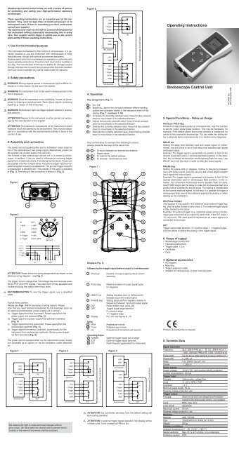
Stroboscope Control Unit provides you with a variety of options<br />
for controlling and setting your high-performance stationary<br />
stroboscope.<br />
Figure 6<br />
6<br />
These operating instructions are an essential part of the instrument.<br />
They must be kept close at hand and passed on to<br />
subsequent users. If there is something you don’t understand,<br />
consult your supplier.<br />
The manufacturer reserves the right to continue development of<br />
this instrument without necessarily documenting this in every<br />
case. Your supplier will be happy to update you on the current<br />
applicability of these operating instructions.<br />
1. Use for the intended purpose<br />
This instrument is intended for the control of stroboscopes. It is generally<br />
possible to use this instrument with stroboscopes of other<br />
manufacturers, though with optional accessories (adapters).<br />
Stroboscope Control Unit must always be operated in conformity with<br />
these operating instructions. The instrument must not be modified in<br />
any way. The manufacturer will accept no liability for damage caused<br />
through improper use or use for any purpose other than that intended.<br />
Such use would invalidate any claims made under the warranty.<br />
2. Safety precautions<br />
+24V<br />
GND<br />
+Trigger<br />
- Trigger<br />
+24V<br />
GND<br />
AC Adapter<br />
+24V<br />
GND<br />
+24V<br />
+ Trigger<br />
- Trigger<br />
ID-Pin<br />
GND<br />
1<br />
3<br />
4<br />
5<br />
1<br />
4<br />
5<br />
2<br />
3<br />
IN<br />
Stroboscope Control Unit<br />
Operating Instructions<br />
<br />
<br />
<br />
<br />
WARNING Moving objects appear in stroboscopic light as either immobile<br />
or in slow motion. Do not touch the objects.<br />
WARNING The instrument must not be used in areas exposed to the<br />
risk of explosion.<br />
WARNING Store the instrument in dry conditions. It must not be exposed<br />
to dripping or spraying water. Never place objects containing<br />
liquids (e.g. vases) on this instrument.<br />
WARNING Stroboscopic light can trigger epileptic attacks in susceptible<br />
persons.<br />
ATTENTION Repairs to this instrument must be carried out exclusively<br />
by the manufacturer or the supplier.<br />
ATTENTION The electronic components of the instrument contain<br />
materials which are harmful to the environment. They must be disposed<br />
of in accordance with the environmental policies in force in the<br />
country of use.<br />
3. Assembly and connection<br />
The power can be supplied either via the installation under observation<br />
or the stroboscope’s own power supply. Alternatively, power can<br />
be supplied via a power supply unit (optional).<br />
The function of the stroboscope control unit is to control a stroboscope.<br />
In addition, it can be used to influence an incoming trigger<br />
signal from an external system. This device has two jacks. Power can<br />
be supplied via either of these jacks. The jack for trigger input from an<br />
external system or sensor is labelled IN. The jack for trigger output to<br />
a stroboscope is labelled OUT. The position of the jacks is indicated<br />
in (Fig. 1). The wiring of the connectors is shown in (Fig. 2).<br />
Figure 1<br />
Figure 2<br />
IN<br />
1 +24V<br />
IN<br />
2<br />
3 GND<br />
4 +Trigger<br />
5 -Trigger<br />
1 +24V<br />
2 ID-Pin<br />
3 GND<br />
4 +Trigger<br />
5 -Trigger<br />
OUT<br />
4 2 5<br />
OUT<br />
1<br />
3<br />
1 +24V<br />
2 ID-Pin<br />
3 GND<br />
4 +24V<br />
5 OUT (NPN) DIN 41 524<br />
(EN 60130-9)<br />
1 2 3 4 5 1 2 3 4 5<br />
IN<br />
OUT<br />
ATTENTION Please follow the wiring assignments as shown on the<br />
attached wiring diagram – see Fig. 2.<br />
The trigger input is voltage-free. The voltage-free contracts are suitable<br />
for PNP and NPN signals. This instrument comes equipped with<br />
a cable and plug that match these input jacks.<br />
4. Operation<br />
1 3 4<br />
5<br />
2<br />
7<br />
8<br />
11<br />
A<br />
C<br />
D<br />
Stroboscope<br />
Key assignment (Fig. 7)<br />
OUT<br />
A = On / Off<br />
B = Mode key. Use this key to switch between different setting<br />
options and operation modes in the sequence shown in the<br />
display (Fig. 7, numbers 1-10)<br />
C = Increases the currently selected value. Keep this key pressed<br />
down to move faster in the selected direction.<br />
D = Halves the currently selected value. Keep this key pressed<br />
down to move faster in the selected direction.<br />
E = Doubles the currently selected value. Keep this key pressed<br />
down to move faster in the selected direction.<br />
F = Reduces the currently selected value. Keep this key pressed<br />
down to move faster in the selected direction.<br />
Key combinations to command the following functions:<br />
Always press the two keys at the same time.<br />
B + D = To switch between an internal and external<br />
trigger signal.<br />
B + F = To reset to the default settings.<br />
A + F = To activate / deactivate key lock.<br />
Figure 7<br />
Displays (Fig. 1)<br />
Influencing the trigger signal before output to a stroboscope<br />
1 PULS µs Duration of output signal pulse (in microseconds).<br />
2 PULS deg Relative duration of output signal pulse<br />
(in degrees).<br />
6<br />
9<br />
10<br />
13<br />
12<br />
B<br />
E<br />
F<br />
Stroboscope Control Unit<br />
5. Special Functions – Notes on Usage<br />
PULS µs / PULS deg<br />
Duration of output signal pulse (in microseconds). Use this function<br />
to set the output signal pulse duration. This may be necessary, for<br />
example, if the default setted short pulse duration is inadequate for<br />
control of the connected stroboscope. You can make this setting either<br />
in absolute terms (microseconds) or in relative terms (degrees).<br />
DELAY ms<br />
Setting the delay time between input and output signal (in milliseconds).<br />
Use this value to set a fixed delay time between input signal<br />
and output signal.<br />
Example: The trigger signal is generated at a position in front of the<br />
desired observation point (= stroboscope flash position). In this situation,<br />
the connected stroboscope would regularly flash too early. Use<br />
DELAY ms to set the value in order to delay the output signal.<br />
PHASE deg<br />
Setting the phase shift (in degrees, relative to frequency) between<br />
input and output signal. Use this value to set a fixed angle between<br />
input signal and output signal.<br />
Example: The trigger signal is generated at a position in front of the<br />
desired observation point (= stroboscope flash position). In this situation,<br />
the connected stroboscope would regularly flash too early.<br />
Use PHASE deg to set the delay to make the stroboscope flash at a<br />
position which is shifted by the set angle. This setting is independent<br />
of the current rotational speed. In this way, it is possible to trigger a<br />
stroboscope flash even if the rotational speed is fluctuating or when<br />
starting up the installation.<br />
DIV (Pulse Divider)<br />
This function is only active in the presence of an external trigger signal.<br />
Use the pulse divider to set a value x. The external trigger signal<br />
is then divided by this value.<br />
Example: An external trigger (e.g. rotational speed sensor) monitoring<br />
a gear wheel delivers a signal for each tooth. If the DIV value =<br />
10, only every 10th input pulse is delivered as an output signal to a<br />
connected stroboscope.<br />
OPT<br />
Trigger signal edge selection. 0 = positive edge, 1 = negative edge.<br />
Use this option to define the polarity of the trigger signal.<br />
6. Scope of supply<br />
• Stroboscope Control Unit<br />
• Operating instructions<br />
• Trigger cable, 1.5 m<br />
• Certificate<br />
• Case<br />
7. Optional accessories<br />
• AC Adapter<br />
• Mounting<br />
• Trigger extension cable<br />
• Adapter for stroboscopes of other manufacturers<br />
NO. N0001.501<br />
Status November 2008<br />
<br />
RECOMMENDATION To wire the trigger signal, use a sheathed<br />
cable.<br />
Typical wiring options:<br />
Please see Figs. 3-6 for examples of wiring options. Please<br />
note that you need optional accessories for the examples (such as<br />
an stationary stroboscope, power supply unit or sensor).<br />
a) Trigger signal from this instrument. Power supply from the<br />
power supply unit (optional) (Fig. 3)<br />
b) Trigger signal and power supply from external installation<br />
(Fig. 4)<br />
c) Trigger signal from this instrument. Power supply from the<br />
stroboscope (optional) (Fig. 5)<br />
d) Trigger signal from sensor (optional), power supply for this<br />
instrument from stroboscope (optional). Sensor power supply<br />
via this instrument (Fig. 6)<br />
The power can be supplied either via the instrument’s power supply<br />
unit (available as an option) or via the installation under observation.<br />
Figure 3 Figure 4 Figure 5<br />
+24V<br />
GND<br />
AC Adapter l<br />
+24V<br />
+ Trigger<br />
- Trigger<br />
ID-Pin<br />
GND<br />
Stroboscope<br />
1<br />
3<br />
1<br />
4<br />
5<br />
2<br />
3<br />
IN<br />
OUT<br />
Stroboscope Control Unit<br />
We reserve the right to make technical changes without<br />
prior notice. We have taken the utmost care to prevent errors.<br />
Liability in the event of any errors shall be excluded.<br />
+24V<br />
GND<br />
+Trigger<br />
- Trigger<br />
Machine<br />
+24V<br />
+ Trigger<br />
- Trigger<br />
ID-Pin<br />
GND<br />
Stroboscope<br />
1<br />
3<br />
4<br />
5<br />
1<br />
4<br />
5<br />
2<br />
3<br />
<br />
<br />
3 DELAY ms Setting the delay time (in milliseconds)<br />
between input and output signal.<br />
4 PHASE deg Setting phase shift (in degrees, relative to<br />
frequency) between input and output signal.<br />
5 DIV Pulse divider, max. value 255.<br />
6 OPT Trigger signal edge selection.<br />
0 = positive edge<br />
1 = negative edge<br />
7 Display For unit, see figures 8 - 10<br />
Units<br />
8 FPM Flashes per minute.<br />
9 1/min Rotations per minute.<br />
10 Hz<br />
Frequency of movement per second.<br />
Operating Notes<br />
12 RANGE External trigger signal out of range<br />
13 EXT External trigger signal selected.<br />
14 INT Flash frequency generated by instrument.<br />
IN<br />
OUT<br />
Stroboscope Control Unit<br />
+24V<br />
GND<br />
AC Adapter<br />
+24V<br />
GND<br />
+24V<br />
+ Trigger<br />
- Trigger<br />
ID-Pin<br />
GND<br />
Stroboscope<br />
1<br />
4<br />
5<br />
2<br />
3<br />
OUT<br />
ATTENTION Any parameter deviating from the default setting will<br />
blink during operation.<br />
ATTENTION In external trigger signal operation, the display will be<br />
in these units: 1/min (instead of FPM) or Hz.<br />
Stroboscope Control Unit<br />
Printed CE-Conformity on request<br />
8. Technical Data<br />
Signal resolution<br />
Frequency 30.0...999.9 FPM ±0,1 0.5...999.9 Hz ±0.1<br />
1.000...600.000 FPM ±1 1.000...10.000 Hz ±1<br />
Pulse width Can be set as either absolute (±1µs) or relative (±1°)<br />
Phase shift 0...359° ±1°<br />
Delay<br />
0.0...2000.0 ms ±0.1 ms<br />
Divider 1...255 ±1<br />
Power supply<br />
Supply voltage 10-32 V DC, with reverse polarity protection<br />
Current consumption < 50 mA<br />
Trigger input<br />
Principle<br />
Optocoupler, voltage-free<br />
Level<br />
3…32 V, NPN + PNP<br />
Low level < 1 V<br />
Minimum pulse length: 50 µs<br />
Reverse voltage protection: yes<br />
Trigger output<br />
Principle<br />
Short-circuit and overvoltage proof transistor<br />
output to the optocoupler control, non-isolated<br />
Level<br />
NPN, max. 32 V<br />
pulse length adjustable<br />
Maximum current 50 mA<br />
Reverse voltage protection: yes<br />
Housing<br />
Material<br />
ABS / EPDM<br />
Size<br />
162x82x40 mm / 6.4x3.3x1.6 inch<br />
Weight<br />
230 g<br />
Ambient conditions<br />
Ambient temperature 0°…50° C (32°…122° F)<br />
Media resilience Max. 95 % air humidity, non-condensing<br />
Protection system IP30