Datenblatt TEMZ 5236 - Schwarzbeck - Mess-Elektronik
Datenblatt TEMZ 5236 - Schwarzbeck - Mess-Elektronik
Datenblatt TEMZ 5236 - Schwarzbeck - Mess-Elektronik

Erfolgreiche ePaper selbst erstellen
Machen Sie aus Ihren PDF Publikationen ein blätterbares Flipbook mit unserer einzigartigen Google optimierten e-Paper Software.
SCHWARZBECK MESS - ELEKTRONIK<br />
An der Klinge 29 D-69250 Schönau Tel.: 06228/1001 Fax.: (49)6228/1003<br />
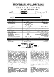
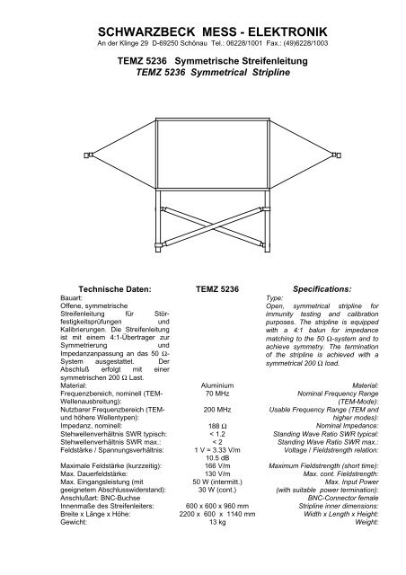
<strong>TEMZ</strong> <strong>5236</strong> Symmetrische Streifenleitung<br />
<strong>TEMZ</strong> <strong>5236</strong> Symmetrical Stripline<br />
Technische Daten: <strong>TEMZ</strong> <strong>5236</strong> Specifications:<br />
Bauart:<br />
Offene, symmetrische<br />
Streifenleitung für Störfestigkeitsprüfungen<br />
und<br />
Kalibrierungen. Die Streifenleitung<br />
ist mit einem 4:1-Übertrager zur<br />
Symmetrierung<br />
und<br />
Impedanzanpassung an das 50 Ω-<br />
System ausgestattet. Der<br />
Abschluß erfolgt mit einer<br />
symmetrischen 200 Ω Last.<br />
Type:<br />
Open, symmetrical stripline for<br />
immunity testing and calibration<br />
purposes. The stripline is equipped<br />
with a 4:1 balun for impedance<br />
matching to the 50 Ω-system and to<br />
achieve symmetry. The termination<br />
of the stripline is achieved with a<br />
symmetrical 200 Ω load.<br />
Material: Aluminium Material:<br />
Frequenzbereich, nominell (TEM-<br />
Wellenausbreitung):<br />
70 MHz Nominal Frequency Range<br />
(TEM-Mode):<br />
Nutzbarer Frequenzbereich (TEMund<br />
höhere Wellentypen):<br />
200 MHz Usable Frequency Range (TEM and<br />
higher modes):<br />
Impedanz, nominell: 188 Ω Nominal Impedance:<br />
Stehwellenverhältnis SWR typisch: < 1.2 Standing Wave Ratio SWR typical:<br />
Stehwellenverhältnis SWR max.: < 2 Standing Wave Ratio SWR max.:<br />
Feldstärke / Spannungsverhältnis: 1 V = 3.33 V/m<br />
Voltage / Fieldstrength relation:<br />
10.5 dB<br />
Maximale Feldstärke (kurzzeitig): 166 V/m Maximum Fieldstrength (short time):<br />
Max. Dauerfeldstärke: 130 V/m Max. cont. Fieldstrength:<br />
Max. Eingangsleistung (mit<br />
geeignetem Abschlusswiderstand):<br />
50 W (intermitt.)<br />
30 W (cont.)<br />
Max. Input Power<br />
(with suitable power termination):<br />
Anschlußart: BNC-Buchse<br />
BNC-Connector female<br />
Innenmaße des Streifenleiters: 600 x 600 x 960 mm Stripline inner dimensions:<br />
Breite x Länge x Höhe: 2200 x 600 x 1140 mm Width x Length x Height:<br />
Gewicht: 13 kg Weight:
SCHWARZBECK MESS - ELEKTRONIK<br />
An der Klinge 29 D-69250 Schönau Tel.: 06228/1001 Fax.: (49)6228/1003<br />
<strong>TEMZ</strong> <strong>5236</strong> Symmetrische Streifenleitung<br />
<strong>TEMZ</strong> <strong>5236</strong> Symmetrical Stripline<br />
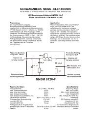
Verwendung:<br />
Die symmetrische Streifenleitung entspricht in<br />
Ihren Abmessungen den Anforderungen der<br />
CISPR 20. Um einen möglichst<br />
ortsunabhängigen Verlauf der Feldstärke zu<br />
erreichen, wird die Streifenleitung mit einem<br />
geeigneten Abschlußwiderstand von 50 Ω<br />
betrieben, der über einen 4:1 Übertrager<br />
transformiert wird. Alternativ kann eine 200 Ω<br />
symmetrische Last verwendet werden. Mit der<br />
Streifenleitung können TEM-Wellen bis max. ca.<br />
70 MHz erzeugt werden. Im TEM-Wellenbetrieb<br />
liegen im gesamten Streifenleiter sehr homogene<br />
Feldverhältnisse vor. Oberhalb von 70 MHz<br />
existieren höhere Wellentypen, bei denen eine<br />
starke Ortsabhängigkeit der Feldstärke vorliegt.<br />
Während bei TEM-Wellenanregung die<br />
Feldstärke am Rand des Streifenleiters gering ist<br />
und zur Mitte hin ansteigt, liegt bei höheren<br />
Wellentypen der umgekehrte Fall vor; man findet<br />
die höchsten Feldstärkewerte am Rande des<br />
Septums, in der Mitte liegt in der Regel ein<br />
Feldstärke-Minimum vor. Darüberhinaus sind bei<br />
hohen Frequenzen Bereiche mit veränderter<br />
Polarisationsrichtung des Feldes vorhanden. Im<br />
Grundwellenbetrieb erfolgt bei leerer Zelle nur<br />
eine sehr geringe Abstrahlung. Weniger als 1 %<br />
der eingespeisten Leistung wird in die Quelle<br />
reflektiert, bedingt durch minimale<br />
Fehlanpassung. Die Leistungsverluste (im<br />
wesentlichen dielektrische Verluste durch die<br />
Kunststoff-Stützen und Abstrahlung) im<br />
Grundwellenbetrieb liegen stets unter 29%. Bei<br />
einer Einfügedämpfung |S21| = 0.5 dB liegen die<br />
Verluste bei 11%, bei |S21| = 1 dB liegen die<br />
Verluste bei ca. 21%. Die Verluste bei höheren<br />
Wellentypen nehmen deutlich zu. Zur<br />
Überwachung der tatsächlich vorhandenen<br />
Feldstärke eignet sich besonders das kompakte,<br />
kostengünstige<br />
netzunabhängige<br />
Feldstärkemessgerät VUFM 1670 und das LCD-<br />
Anzeigeteil VUFM 1671, die per Lichtwellenleiter<br />
verbunden sind. Zur Positionierung der Prüflinge<br />
sollten dielektrisch nahezu neutrale Werkstoffe<br />
verwendet werden, z.B. Schaumgummi oder<br />
Styroporplatten. Die Eignung eines Werkstoffes<br />
kann untersucht werden, indem zunächst die<br />
Einfügedämpfung bei leerer Zelle und<br />
anschließend mit dem zu untersuchenden<br />
Werkstoff gemessen wird. Gut geeignete<br />
Werkstoffe weisen eine minimale<br />
Dämpfungserhöhung auf. Die Prüflinge sollten so<br />
gut wie möglich mittig im Streifenleiter plaziert<br />
werden. Zur Erhöhung der Reproduzierbarkeit<br />
sollte die exakte Positionierung der Prüflinge<br />
dokumentiert werden.<br />
Application:<br />
The symmetrical stripline complies to the<br />
requirements of CISPR 20. In order to<br />
achieve a smooth fieldstrength characteristic<br />
throughout the length, the stripline is<br />
terminated with 50 Ω, transformed via a 4:1<br />
balun. Alternatively a symmetrical 200 Ω<br />
termination can be used. The stripline can be<br />
used to create TEM-waves up to max. 70<br />
MHz. The fieldstrength distribution at TEMmode<br />
operation inside the stripline is very<br />
homogenous. The stripline can also be used<br />
above 70 MHz, in this case higher modes do<br />
exist, which offer a location dependant<br />
fieldstrength characteristics. In contrast to the<br />
TEM-mode, where the fieldstrength is small<br />
at the edge of the stripline and increases<br />
towards the center, the higher modes show<br />
opposite characteristics: the fieldstrength is<br />
small at the center of the stripline and rises to<br />
maximum values at the edge of the strip<br />
conductor. Further the direction of<br />
polarisation changes at some areas during<br />
multi mode operation. At TEM-mode<br />
operation there are only small losses caused<br />
by radiation and dielectrical losses of the<br />
plastic support rods. Less than 1% of the<br />
incident power is reflected back into the<br />
source, caused by minimized impedance<br />
mismatch. The dielectric and radiation losses<br />
at TEM operation frequencies are as follows:<br />
|S21| = 0.5 dB, losses: 11%, |S21| = 1.0 dB,<br />
losses: 21%. The losses increase for multi<br />
mode operation.<br />
An ideal tool for monitoring the actual<br />
fieldstrength inside the stripline is the VUFM<br />
1670 field meter with the VUFM 1671 LCDdisplay<br />
unit, which are connected via a fibre<br />
optical link.<br />
For positioning of the EuT it is recommended<br />
to use (nearly) dielectric neutral material, e.g.<br />
foam or polystirene plastics. The suitability of<br />
the material can be checked as follows: the<br />
insertion loss of the empty cell is measured,<br />
then the material under test is placed in the<br />
cell and the insertion loss is measured again.<br />
Minimum differences in attenuation of the<br />
empty and loaded cell indicate a suitable<br />
material. The equipment under test (EuT)<br />
should be placed in the center of the stripline.<br />
It is recommended to record the EuT-position<br />
as exactly as possible in order to achieve a<br />
good reproducability of the tests.
SCHWARZBECK MESS - ELEKTRONIK<br />
An der Klinge 29 D-69250 Schönau Tel.: 06228/1001 Fax.: (49)6228/1003<br />
<strong>TEMZ</strong> <strong>5236</strong> Symmetrische Streifenleitung<br />
<strong>TEMZ</strong> <strong>5236</strong> Symmetrical Stripline<br />
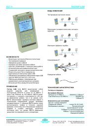
0<br />
Transmission von zwei Übertragern (ohne Streifenleitung)<br />
Insertion Loss of two Baluns<br />
-0.2<br />
-0.4<br />
-0.6<br />
-0.8<br />
S 21 [dB]<br />
-1<br />
-1.2<br />
-1.4<br />
-1.6<br />
-1.8<br />
-2<br />
0.01 0.1 1 10 100<br />
Frequency [MHz]<br />
0<br />
Transmission der <strong>TEMZ</strong> <strong>5236</strong> mit zwei Übertragern<br />
Insertion Loss of <strong>TEMZ</strong> <strong>5236</strong> with two Baluns<br />
-2<br />
-4<br />
S 21 [dB]<br />
-6<br />
-8<br />
-10<br />
0.01 0.1 1 10 100<br />
Frequency [MHz]
SCHWARZBECK MESS - ELEKTRONIK<br />
An der Klinge 29 D-69250 Schönau Tel.: 06228/1001 Fax.: (49)6228/1003<br />
<strong>TEMZ</strong> <strong>5236</strong> Symmetrische Streifenleitung<br />
<strong>TEMZ</strong> <strong>5236</strong> Symmetrical Stripline<br />
100<br />
Impedanz der <strong>TEMZ</strong> <strong>5236</strong> am 4:1 Übertrager<br />
Impedance of <strong>TEMZ</strong> <strong>5236</strong> via 4:1 Balun<br />
80<br />
60<br />
|Z| [Ohm]<br />
40<br />
20<br />
0<br />
0.01 0.1 1 10 100<br />
Frequency [MHz]<br />
Feldstärke und erforderliche Eingangsleistung<br />
<strong>TEMZ</strong> <strong>5236</strong><br />
100<br />
50<br />
Fieldstrength [V/m]<br />
20<br />
10<br />
5<br />
SWR = 1.0<br />
SWR = 2.0<br />
2<br />
1<br />
0.01 0.1 1 10<br />
Input Power [W]