
Sie wollen auch ein ePaper? Erhöhen Sie die Reichweite Ihrer Titel.
YUMPU macht aus Druck-PDFs automatisch weboptimierte ePaper, die Google liebt.
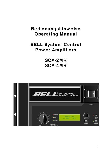
Bedienungshinweise<br />
Operating Manual<br />
BELL System Control<br />
Power Amplifiers<br />
SCA-2MR<br />
SCA-4MR<br />
1
Inhaltsverzeichnis:<br />
Bedienelemente (Rückseite) Seite 3<br />
Bedienelemente (Front) Seite 4<br />
Funktionsablauf Seite 6<br />
View Mode Seite 7<br />
Command Mode Seite 10<br />
English manual:<br />
Operational Features (rear panel) page 14<br />
Operational Features (front panel) page 15<br />
Functions and features (guideline) page 17<br />
View Mode page 18<br />
Command Mode page 21<br />
Specifications SCA2MR <strong>SCA4MR</strong><br />
Power Output<br />
Freq. Resp.<br />
SNR(IHF-A)<br />
Input Sensitivity<br />
Signal LED Indicator L&R<br />
Protect LED Indicator L&R<br />
500+500W/4Ω<br />
10Hz - 40kHz/8Ω<br />
110dB<br />
2,7dBu(1,06Vrms)<br />
LED<br />
LED<br />
1000+1000W/4Ω /2Ω<br />
10Hz - 40kHz / 8Ω<br />
110dB<br />
2,7dBu(1,06Vrms)<br />
LED<br />
LED<br />
Limit LED Indicator<br />
L&R<br />
LED<br />
LED<br />
Cooling Control System<br />
Temperature Indicator<br />
SCM Module Indicator<br />
Input Damping readout<br />
automatic<br />
LCD Display<br />
LCD Display<br />
LCD Display<br />
automatic<br />
LCD Display<br />
LCD Display<br />
LCD Display<br />
2
Bedienelemente (Rückseite)<br />
SCA2MR<br />
Netzbuchse Euro:<br />
Mains Fuse:<br />
230VAC<br />
8AT (träge)<br />
<strong>SCA4MR</strong><br />
Netzbuchse Powercon: 230VAC<br />
Mains Fuse:<br />
15AT (träge)<br />
Secondary Fuse: 1AT (träge)<br />
System Control Module (SCM modules) (SCA2MR / <strong>SCA4MR</strong>)<br />
Die verwendeten Eingangsmodule sind mit denen der Baureihe SCA2 kompatibel.<br />
XLR Eingang / Link CH.A / CH.B<br />
ACHTUNG: Die Modelle SCA2MR und <strong>SCA4MR</strong> sind mit einer Schutzschaltung<br />
gegen Überspannung am Eingang ausgestattet. Zur ordnungsgemäßen Funktion und<br />
zur Vermeidung von Verzerrungen müssen alle über NF Kabel (XLR) eingangsseitig<br />
verbundenen Endstufen netzseitig eingeschaltet sein!<br />
Shield Lift Schalter mit LED Anzeige für Input CH.A / CH.B.<br />
Shield Lift aktiv (grüne LED an) bewirkt, daß die Abschirmung des Eingangskabels,<br />
welches im Normalfall Massepotential hat, von der Masse der Endstufe getrennt ist.<br />
Es ist darauf zu achten, daß mindestens eine Masseverbindung zwischen Mischpult<br />
und jeder einzelnen Endstufe besteht, da alle Eingänge elektronisch symmetrisch sind.<br />
GND / LIFT Schalter<br />
In „GND“ Position ist die Schutzerde mit der Masse der Endstufe verbunden. Brummschleifen<br />
können ggfls. durch Umschalten in Position „LIFT“ aufgehoben werden.<br />
Data IN<br />
XLR Buchse + Link für den Dateneingang der RS485 Schnittstelle. Dient zur Fernsteuerung<br />
/ Überwachung der SCA-2/4MR.<br />
(Funktion steht mit der Software Release 1.0 noch nicht zur Verfügung).<br />
Impedance Mode Schalter mit Led (SCA-4MR)<br />
Anpassung der Verlustleistung für optimierte Betriebssicherheit in Abhängigkeit<br />
zu der an den Lautsprecherausgängen angeschlossenen Impedanz. Der gewählte<br />
Modus wird im Display [View Mode , Page 1] angezeigt.<br />
Der 4 Ω Mode wird zusätzlich durch die gelbe Led (an) gekennzeichnet.<br />
Die pro Lautsprecherausgang angeschlossene Gesamtast darf im 2Ω Mode die Impedanz<br />
von 2Ω und im 4Ω Mode die Impedanz von 4Ω nicht unterschreiten.<br />
Das Umschalten des Impedanz Modus während des Betriebs ist zu vermeiden.<br />
Temperaturgesteuerte Lüfter<br />
Air flow direction: to front. Rack im Betrieb vorne und hinten offen halten.<br />
3
Bedienelemente Front<br />
Netzschalter (Mains)<br />
Einschalten der Endstufe zum Normal- und Standby Betrieb. Anzeige über Hintergrundbeleuchtung<br />
der Dispays.<br />
Level Regler (CH.A / B)<br />
Einstellung der Dämpfung des Eingangssignals in ‚dB‘. Der eingestellte Wert wird im<br />
Display angezeigt. [View Mode , Page 1] Dämpfung: max 88dB, min. 0.0dB.<br />
Remote Active Schalter (mit Led)<br />
Aktiviert den Remote Control Modus. Anzeige durch rote Led (an).<br />
Das Aktivieren/Deaktivieren des Remote Control Modus erfolgt zusätzlich über einen<br />
„Fade In“ um einen eventuellen Pegelunterschied während des Betriebs sanft auszugleichen.<br />
Remote Control Modus*<br />
ermöglicht die Fernsteuerung und -überwachung der Endstufe mittels externem<br />
Controller. Der Datenaustausch erfolgt via RS485 Schnittstelle. Alle notwendigen<br />
Parameter werden im [Command Mode, Page 1] eingestellt.<br />
Das Aktivieren dieses Modus kann vom User per Software unterdrückt werden.<br />
[Command Mode, Page 4]. Ist Remote Control aktiv, so ist der „Command Mode“ automatisch<br />
deaktiviert um interne und externe Überlagerung von Befehlen zu verhindern.<br />
*Diese Funktion steht in der Software Release 1.0 nicht zur Verfügung.<br />
Command Schalter (mit Led)<br />
Wechselt zu einem beliebigen Zeitpunkt zwischen „Command“- und „View Mode“.<br />
Der „Command Mode“ wird zusätzlich durch das Leuchten der grünen Led gekennzeichnet.<br />
Bei Verlassen des „Command Mode“ wird der zuletzt geänderte Wert automatisch<br />
gespeichert, auch wenn dieser vorher nicht mit „Enter“ bestätigt wurde.<br />
Das Aktivieren des „Command Mode“ kann mittels Keycode geschützt werden.<br />
[Command Mode , Page 5]<br />
Siehe auch Erklärung der Funktionen „Command“- und „View Mode“<br />
Page/Exit Taste<br />
Wechselt im „Command“- und „View Mode“ zur nächsten Seite. Hierbei wird automatisch<br />
der zuletzt geänderte Wert gespeichert, auch wenn dieser nicht mit „Enter“ bestätigt<br />
wurde.<br />
Set/Enter<br />
Durch Drücken des Wheels wird die Funktion „Enter“ ausgeführt. Durch<br />
Drehen des Wheels nach links oder rechts wird die Funktion „Set“ ausgeführt.<br />
Enter<br />
springt im Command Mode von einem zu ändernden Parameter zum nächsten. Dabei<br />
werden die Daten, falls verändert, gespeichert. Der zu ändernde Parameter wird im<br />
Display blinkend dargestellt. Enter bestätigt bei numerischen Eingaben die einzelne<br />
Ziffer (z.B. bei Eingabe des Keycodes).<br />
4
Set<br />
Ändert im „Command Mode“ den Wert der einzelnen Parameter. Diese Werte können<br />
sowohl numerisch als auch Bestätigungen (YES / NO, ON / OFF oder ENABLE /<br />
DISABLE) sein.<br />
Display mit Hintergrundbeleuchtung CH.A / CH.B<br />
Anzeige aller Informationen im Command- und View Mode, sowie eventueller<br />
Warnhinweise im Protect Mode.<br />
SIGNAL LED<br />
Anzeige eines durch die XLR Eingangsbuchsen ankommenden NF Signals.<br />
Im Normalbetrieb leuchten nur die grünen Signalanzeigen auf.<br />
LIMIT LED<br />
Zeigt das Arbeiten des integrierten Limiters an.Bei längerem Aufleuchten dieser Anzeige<br />
sollte der Eingangspegel (= Ausgangspegel des angeschlossenen Mixers) abgesenkt<br />
werden um eine zu starke Komprimierung des Eingangssignals zu vermeiden.<br />
PROTECT LED<br />
Warnt vor einem Defekt, oder vor Übertemperatur der Endstufe. (Bei Übertemperatur ab<br />
90¯C wird Protect ausgelöst. Bei Abkühlen auf ca. 80° wird Protect deaktiviert.<br />
Siehe auch [View Mode , Page 1] Die Ursache für Übertemperatur ist unbedingt zu<br />
beseitigen.<br />
Im Protect Mode werden die angeschlossenen Lautsprecher via Relais vom<br />
Lautsprecherausgang getrennt. Falls sich die SCA-2/4MR bereits während des Einschaltens<br />
im Protect Mode befindet, wird dies direkt nach dem „Initialisieren“ des Systems<br />
für ca. 5s in Display angezeigt.<br />
Falls im [Command Mode , Page 4] die „Auto Power OFF“ Schaltung aktiviert wurde,<br />
wird die Endstufe automatisch in den „Standby Mode“ (spannungsfrei) geschaltet.<br />
Sie wird somit zusätzlich gegen mögliche Folgen von Überlastung geschützt.<br />
Eine genaue Beschreibung dieser Funktion findet sich unter ‚Funktionsablauf‚ (Punkt 3).<br />
Im Protect Mode sind folgende Funktionen deaktiviert:<br />
[View Mode , Page 3]<br />
[View Mode , Page 4]<br />
[View Mode , Page 5]<br />
[Command Mode , Page 2]<br />
[Command Mode , Page 3]<br />
5
Funktionsablauf<br />
1) Vor dem Einschalten der Endstufe ist durch den „Impedance Mode“ Schalter (Rückseite)<br />
die angeschlossene Last (Lautsprecher) zu wählen: 2Ω / 4Ω (nur bei <strong>SCA4MR</strong>).<br />
Werden pro Seite Lautsprecher mit einer Gesamtimpezanz von grösser gleich 4Ω<br />
betrieben, so ist der 4Ω Mode einzustellen. Werden pro Seite Lautsprecher mit einer<br />
Gesamtimpedanz unter 4Ω betrieben, so ist der 2Ω Mode zu wählen.<br />
Anzeige des gewählten Modus im Display [View Mode , Page 1].Der 4 Ω Mode wird<br />
zusätzlich durch eine gelbe Led (neben Imepdance Mode Schalter) angezeigt.<br />
Das Umschalten des Impedance Modus des Betriebs während des Betriebs ist zu<br />
vermeiden.<br />
2) Nach dem Einschalten der SCA-2MR/4MR wird das System des Amps initialisiert.<br />
Hierbei zeigen die Displays folgende Information:<br />
3) Falls im [Command Mode, Page 4] der „Sine Wave Test“ aktiviert wurde, wird dieser<br />
jetzt ausgeführt. Dieser Test dient der Überprüfung der am Lautsprecherausgang angeschlossenen<br />
Komponenten.<br />
Das System überprüft innerhalb des zuvor gewählten Frequenzbereichs mit der gewählten<br />
Verstärkerausgangsleistung [Command Mode , Page 2/3] die Gesamtimpedanz<br />
der pro Verstärkerseite angeschlossenen Lautsprecher incl. Kabel.<br />
Das Scannen des jeweiligen Frequenzfensters ist akustisch, in Abhängigkeit zur programmierten<br />
Ausgangsleistung, durch das angeschlossene Lautsprechersystem zu<br />
hören. Warnung - Vorsicht bei zu hoher Lautstärke !!!<br />
Das Testergebnis wird auf den Displays für den jeweiligen Endstufenkanal (CH.A /<br />
CH.B) separat angezeigt.<br />
Falls im [Command Mode , Page 4] die „Auto Power OFF“ Schaltung aktiviert wurde<br />
und das System an einem der beiden Lautsprecherausgänge einen Kurzschluß oder<br />
Unterimpedanz (R
Falls im [Command Mode , Page 5] „Keycode“ aktiviert wurde, zeigen die Displays<br />
folgende Information:<br />
A<br />
Der „Standby Mode“ kann nur aufgehoben werden wenn die Ursache des Fehlers beseitigt<br />
wird, oder der korrekte Keycode eingegeben wird, um die Fenster zum<br />
Deaktivieren von „Power Control“ und „Sine TEST“ zu öffnen.<br />
B<br />
Wird jetzt in diesem neuen Fenster „Power Control“ deaktiviert, so wird nach erneutem<br />
Einschalten der Endstufe der „Standby Mode“ auch dann nicht aktiviert, wenn sich z.B.<br />
ein Kurzschluß am Lautsprecherausgang befindet.<br />
Bei aktiviertem „Sine Wave Test“ ist das Deaktivieren von und „Power Control“ nicht<br />
ratsam!<br />
Falls im [Command Mode, Page 5] der „Keycode“ nicht aktiviert wurde, zeigen die<br />
LCD’s gleich die neben ‚B‘ gezeigten Informationen.<br />
4) Falls der Eingangslevel von CH.A oder CH.B eine geringere Dämpfung als -30dB hat<br />
[View Mode , Page 1] wird jetzt die „Auto Fade In“ Funktion aktiviert.Diese Funktion<br />
fährt den Ausgangspegel der Endstufe sanft hoch und verhindert so einen sprunghaften<br />
Lautstärkeanstieg bei anliegendem Eingangssignal.<br />
5) In Abhängigkeit des „Command“ Schalters werden nun auf den Displays die Funktionen<br />
des „Command“- oder „View“ Mode dargestellt.<br />
View Mode<br />
Das Aktivieren dieser Funktion erfolgt durch Umschalten des „Command“ Schalters.<br />
(Grüne Led aus) wenn der View Mode aktiviert wurde. Die Anwahl der nächsten Seite<br />
erfolgt durch die „Page/Exit“ Taste.<br />
Page 1<br />
7
Dargestellte Parameter<br />
SCM Module<br />
Zeigt den Typ des eingebauten SCM (Control Moduls) für CH.A und CH.B an.<br />
Impedance Mode (<strong>SCA4MR</strong>)<br />
Zeigt den mittels Impedance Mode Schalter gewählten Betriebsmodus (2 Ω/ 4 Ω) an.<br />
Level<br />
Die mit dem Level Regler, bzw. per Remote Control eingestellte Dämpfung des Eingangssignals<br />
in „dB“ für CH.A und CH.B.<br />
Heat sink temperature<br />
Anzeige der Betriebstemperatur In °C für CH.A und CH.B.<br />
Page 2<br />
Dargestellte Parameter<br />
Remote address:<br />
Baud Rate:<br />
Remote Level:<br />
Remote Control Adresse der einzelnen Endstufe<br />
Übertragungsgeschwindigkeit der RS485 Schnittstelle<br />
Die im Command Mode bzw per Remote Control<br />
eingestellte Dämpfung des Eingangssignals in „dB“<br />
für CH.A und CH.B<br />
Page 3<br />
Dargestellte Parameter<br />
Output power<br />
Anzeige der Endstufenausgangsleistung von CH.A und CH.B in Watt (True RMS). -<br />
numerisch und als Bargraph.<br />
Die Skalierung des Bargraph beträgt bei der <strong>SCA4MR</strong> 100W / Div. = 50W per angezeigtem<br />
Bargraphsegment.<br />
Die Skalierung des Bargraph beträgt bei der SCA2MR 50W/Div., = 25W per angezeigtem<br />
Segment.<br />
8
Page 4<br />
Dargestellte Parameter:<br />
Output level:<br />
Die Endstufenaussteuerung in „dB“ (True RMS) numerisch und als<br />
Bargraph für CH.A und CH.B .<br />
Die Skalierung des Bargraph beträgt 2dB/Div, d.h. 1dB per dargestelltem<br />
Bargraphsegment . Vollaussteuerung = 0dB.<br />
Page 5<br />
Dargestellte Parameter:<br />
Output voltage:<br />
Output current:<br />
Ausgangsspannung in „V“ (True RMS) für CH.A und CH.B in<br />
0.25V Schritten .<br />
Der Ausgangsstrom in „A“ (True RMS) für CH.A und CH.B in<br />
0.125A Schritten.<br />
Page 6<br />
Dargestellte Parameter:<br />
Sine Wave Test: Status: ON / OFF<br />
Power Control: Status: ON / OFF<br />
TXD: Status: Symbol bei Daten senden über RS485<br />
RXD: Status: Symbol bei Daten empfangen über RS485<br />
9
Command Mode<br />
Das Aktivieren dieser Funktion erfolgt mit dem „Command“ Schalter (grüne LED an)<br />
Eine ausführliche Beschreibung dieser Funktion befindet sich unter:<br />
Bedienungselemente auf der Frontwand, „Command“ Schalter.<br />
Das Anwählen und Bestätigen des zu ändernden Parameters erfolgt mit der „Enter“<br />
Taste des Wheels.<br />
Eine ausführliche Beschreibung dieser Funktion befindet sich unter:<br />
Bedienungselemente auf der Frontwand, „ENTER“.<br />
Das Ändern des angewählten Parameters erfolgt mit dem „Wheel“.<br />
Eine ausführliche Beschreibung dieser Funktion befindet sich unter:<br />
Bedienungselemente auf der Frontwand, „SET „.<br />
Das Anwählen der nächsten Seite erfolgt mit der „Page/Exit“ Taste.<br />
Eine ausführliche Beschreibung dieser Funktion befindet sich unter:<br />
Bedienungselemente auf der Frontwand, „Page / Exit „.<br />
Page 1<br />
Parameter:<br />
Remote address:<br />
Remote Control Adresse der einzelnen Endstufe.<br />
Einstellbarer Wertebereich: 1 - 225. Der Datenaustausch zwischen allen Endstufen und<br />
dem externen Controller erfolgt über die RS485 Schnittstelle. Um eine bestimmte Endstufe<br />
direkt anzusprechen benötigt der Controller deren genaue Adresse.<br />
Diese Adresse darf jeweils nur einmal für eine SCA-2/4MR vergeben werden, um eine<br />
Datenkonflikt zu vermeiden.<br />
Baud Rate:<br />
Baud.<br />
Remote Level:<br />
Die Übertragungsgeschwindigkeit der RS485 Schnittstelle in<br />
Einstellbarer Wertebereich: 9600 / 19200 / 28800 / 57600 .<br />
Dämpfung des Eingangssignals in „dB“ für CH.A und CH.B, wenn<br />
„Remote Control“ aktiviert wurde.<br />
Dieser voreingestellte Wert wird vom System übernommen, falls noch keine Kommunikation<br />
zwischen externem Controller und SCA-2/4MR stattgefunden hat. Einstellbarer<br />
Wertebereich: -88dB - 0.0dB .<br />
10
Page 2<br />
Diese Funktion dient der Überprüfung der am Lautsprecherausgang angeschlossenen<br />
Komponenten mit Hilfe eines durchstimmbaren, digitalen Sinusgenerators. Die Ausgangsleistung<br />
, Start- und Stoppfrequenz des Generators sind frei programmierbar.<br />
Die hier festgelegten Werte werden auch für die automatische Impedanzkontrolle nach<br />
dem Einschalten der SCA-2/4MR verwendet, falls diese unter [Command Mode , Page<br />
4] aktiviert wurde. (Siehe auch unter Funktionsablauf , Punkt 3 ).<br />
Das System überprüft innerhalb des zuvor eingestellten Frequenzbereichs mit der zuvor<br />
eingestellten Verstärkerausgangsleistung die Gesamtimpedanz der pro Kanal angeschlossenen<br />
Lautsprecher incl. Kabel.<br />
Das Scannen der jeweiligen Frequenz ist akustisch, in Abhängigkeit zur programmierten<br />
Ausgangsleistung durch die angeschlossenen Lautsprecher zu hören.<br />
—> Vorsicht bei zu hoher Lautstärke !!!<br />
Das Testergebnis wird auf den Displays für ca. 5s angezeigt.<br />
Im Gegensatz zur automatischen Impedanzkontrolle besteht hier nicht die Möglichkeit<br />
im Fall einer analysierten „Unterimpedanz“ die Endstufe in den „Standby“ Mode zu<br />
schalten.<br />
Vielmehr wird die Ausgangsleistung des Sinussignals auf 4W max. reduziert, um die<br />
Belastung der Endstufe im Fall eines Kurzschlusses zu minimieren.<br />
Gleiches gilt für die automatische Impedanzkontrolle.<br />
Nach Abschluss des Tests erfolgt ein „Fade In“ des Eingangssignals um einen sprunghaften<br />
Anstieg der Lautstärke auf ggfls. bis zu 1000W sanft auszugleichen, falls die<br />
Dämpfung des Eingangssignals kleiner -30dB ist.<br />
Parameter<br />
Output Power: Ausgangsleistung des Sinusgenerators in Watt für Kanal A.<br />
Diese Leistungsangabe bezieht sich bei der SCA-2MR auf 4Ω und bei der SCA-4MR<br />
auf 2Ω bzw. 4Ω (je nach gewähltem Impedanz Modus).<br />
Die Meßgenauigkeit der Impedanzprüfung steigt mit zunehmender Ausgangsleistung.<br />
Es muss daher ein Kompromiss zwischen Lautstärke und Messgenauigkeit gefunden<br />
werden.<br />
Einstellbarer Wertebereich: 2W / 4W / 8W / 16W / 32W / 64W / 128W .<br />
11
Start:<br />
Stop:<br />
Test:<br />
Startfrequenz des digitalen Sinusgenerators. Um Frequenzüberlappungen<br />
zu verhindern, ist diese maximal gleich der Stoppfrequenz.<br />
Einstellbarer Wertebereich: 50Hz - 10KHz .<br />
Stopfrequenz des digitalen Sinusgenerators. Um Frequenzüberlappungen<br />
zu verhindern, ist diese minimal gleich der Startfrequenz.<br />
Einstellbarer Wertebereich: 50Hz - 10KHz .<br />
Startet die Testprozedur.<br />
Einstellbarer Wertebereich: YES / NO .<br />
Page 3<br />
Diese Funktion ist identisch mit der von Page 2, überprüft jedoch CH. B .<br />
Page 4<br />
Parameter:<br />
Sine Test:<br />
Power CTRL:<br />
Aktiviert die automatische Impedanzkontrolle.<br />
Siehe Funktionsablauf , Punkt 3 .<br />
Einstellbarer Wertebereich: ON / OFF.<br />
Aktiviert die „Auto Power Off“ Schaltung.<br />
Siehe Bedienungselemente auf der Frontwand -PROTECT LED<br />
sowie auch Funktionsablauf , Punkt 3 .<br />
Einstellbarer Wertebereich: ON / OFF.<br />
Remote Control: Erlaubt / verbietet das Aktivieren des Remote Control Modus mit dem<br />
„Remote Active“ Schalter. Siehe Bedienungselemente auf der Frontwand -“Remote<br />
Active“ Schalter. Einstellbarer Wertebereich: ENABLE / DISABLE .<br />
*(Funktion steht mit der Software Release1.0 nicht zur Verfügung).<br />
Page 5<br />
12
Parameters:<br />
Keycode: Aktiviert den vierstelligen Keycode. Nach dessen Eingabe wird der<br />
Command Mode nur noch durch Eingabe des Keycode<br />
zugänglich.Diese Funktion verhindert unbefugte Änderung von Daten.<br />
Der Keycode kann erst aktiviert werden, wenn zuvor mit Hilfe der Funktion „New<br />
Keycode“ eine Code eingegeben und gespeichert wurde.Einstellbarer Wertebereich:<br />
ENABLE / DISABLE .<br />
New Keycode: Eingabe oder Änderung eines vierstelligen, numerischen Codes.<br />
Die Änderung des Keycodes ist nur nach vorheriger Eingabe des ursprünglichen<br />
Codes möglich.<br />
Einstellbarer Wertebereich: YES / NO und 0 - 9.<br />
Den Keycode unbedingt an einer sicheren Stelle aufbewahren. Entsperren bei verlorenem<br />
Keycode ist nur durch kostenpflichtigen Service möglich.<br />
13
Operational Features (rear panel)<br />
SCA2MR<br />
Mains socket with integrated fuse holder<br />
Socket typ: 230VAC, Euro type.<br />
Fuse: 8AT (slow blow).<br />
<strong>SCA4MR</strong><br />
Mains socket: Powercon: 230VAC<br />
Mains Fuse: 15AT (slow blow).<br />
Secondary Fuse: 1AT (slow blow).<br />
System Control Module (SCA2MR / <strong>SCA4MR</strong>)<br />
The system control modules (SCM modules) are compatible with those used in the<br />
SCA2M power amplifier.<br />
XLR Input / Link CH.A / CH.B<br />
Warning: Both models SCA2MR and <strong>SCA4MR</strong> feature protection cirtuits against<br />
overvoltage. For proper function and to avoid audible distortion, all power amps which<br />
are connected via XLR input cables must be connected to Mains and must be switched<br />
on.<br />
Shield Lift switch with LED indicator for Input CH.A / CH.B.<br />
Shield Lift active (green LED on) cuts the screen of the incoming signal cable from the<br />
Ground of the Power Amplifier.<br />
In any case, at least one Ground connection (screen) between the signal source<br />
(mixer) and each power amplifier must be connected (all inputs are electronically<br />
balanced).<br />
GND / LIFT Switch<br />
When in „GND“ position, the Earth (Mains) is connected to GND (ground) of the power<br />
amplifier circuit. Humnoise from ground loops may be eliminated by setting the switch<br />
to ‚LIFT‘ position.<br />
Data IN<br />
XLR socket + link for data input from RS485 port. Feature for remote control and remote<br />
operation.(function not activated in software release 1.0 )<br />
Impedance Mode switch with Led indicator (SCA-4MR)<br />
feature to optimize the drain power and the safe operation of the amplifier in connection<br />
with the impedance of the driven loudspeaker(s). Selected mode is shown in the<br />
frontside display [View Mode , Page 1].<br />
In addition, the 4Ω mode is indicated by a yellow Led (on).<br />
In 2Ω mode, the total load connected to each speaker output must not drop under 2Ω.<br />
In 4Ω mode the minimum impedance is 4Ω.<br />
Do not manipulate the impedance mode switch while power amplifier is in use.<br />
Automatic temperature controlled cooling fans<br />
Air flow direction:back to front. Keep airflow free from any kind over covers.<br />
14
Operational Features (front panel)<br />
Mains switch<br />
On/ off switch for normal- and standby operation. ‚ON‘ is indicated by the backlights of<br />
the LCD displays.<br />
Level Control (CH.A / B)<br />
Sets the input signal damping in ‚dB‘. The actual setting is shown in the display.<br />
[View Mode , Page 1] damping: max 88dB, min. 0.0dB.<br />
Remote Active switch with led indicator<br />
Activates the remote control mode. ( red Led (on)).<br />
The remote control mode works in parallel to a ‚fade in‘ function to avoid harsh level<br />
offsets.<br />
Remote Control Mode*<br />
Enables the remote control and supervision of the SCA2MR /4MR using an external<br />
control unit. Data exchange via RS485 port. All necessary parameters are to be<br />
selected in [Command Mode, page 1].<br />
This mode may be disabled by the user.<br />
[Command Mode, Page 4]. When remote control is active, the „command mode“ will be<br />
automatically deactivated to avoid software conflicts.<br />
*this function is not activated in software release 1.0<br />
Command switch (with led indicator)<br />
Switches at any time from „Command“- to „View Mode“ and reverse.<br />
„Command Mode on“ is indicated by an addition green led indicator. When leaving<br />
„Command Mode“ any manipulation of parameters will automatically be safed, even<br />
when ‚Enter‘ was not operated.<br />
„Command Mode“ section may be protected by a keycode (numeric password).<br />
[Command Mode , Page 5]<br />
Re.: functions of „Command“- und „View Mode“<br />
Page/Exit button<br />
Jumps to the next page ( in „Command“- and „View Mode“) Any manipulation of<br />
data will automatically be safed without operating ‚Enter‘ button.<br />
Set/Enter<br />
By pushing the wheel, the „Enter“ order is executed. Turning the wheel to either<br />
direction will activate the ‚Set‘ function.<br />
Enter<br />
In Command Mode pressing ‚Enter‘ will jump from parameter to parameter. Any<br />
manipulation of data will automatically be stored. The next parameter to be modified is<br />
shown in cursor mode. Press enter for each new digit to be stored.<br />
15
Set<br />
When in „Command Mode“ , set will manipulate the values of individual parameters.<br />
These entries may be numeric or confirmations such as YES / NO , ON / OFF or<br />
ENABLE / DISABLE.<br />
LCD Display with backlight CH.A / CH.B<br />
Display of all important data and messages in Command- and View Mode plus eventual<br />
warnings in Protect Mode.<br />
SIGNAL LED<br />
Indicates ‚signal present at amplifier output socket‘<br />
Normally, only the ‚gren‘ led indicators will be on.<br />
LIMIT LED<br />
Indicates that the built-in limiters are active. When this indication is permanent, please<br />
reduce the input level (= the output level of the connected mixer) to avoid heavy<br />
compression of the audio signal.<br />
PROTECT LED<br />
Indicates a defect or a state of overheat. When the temperature of the power amplifiers<br />
exceeds 90°C, Protect will be active. After cooling down to below 80°C, Protect will be<br />
inactivated. [View Mode, Page 1] The physical cause of Protect must be found and<br />
eliminated.<br />
Protect Mode will disconnect the speaker outputs via relais. Should the SCA-2/4MR<br />
remain in Protect Mode after any initial ‚mains on‘, this state will be indicated for<br />
a period of 5sec. after ‚INIT‘<br />
If [Command Mode , Page 4] „Auto Power OFF“ has been activated, the power<br />
amp section will switch to „Standby Mode“ (power supply off).<br />
This feature serves to protect the power amplifier from additional overload.<br />
Fore further information, please refer to ‚Function Guide‚ (page 3).<br />
Protect - Mode will deactivate the following features:<br />
[View Mode , Page 3]<br />
[View Mode , Page 4]<br />
[View Mode , Page 5]<br />
[Command Mode , Page 2]<br />
[Command Mode , Page 3]<br />
16
Functions and features (guideline)<br />
1) Before switching on ‚mains‘, the Impedance Mode switch (rear panel) must be set to<br />
match the minimum impedance of the connected loudspeaker(s).<br />
2Ω / 4Ω (only for <strong>SCA4MR</strong>). When the total speaker impedance for one channel is<br />
below 4Ω, set the impedance switch to 2Ω. In any other case set it to 4Ω<br />
Impedance setting is shown in display [View Mode , Page 1].In addition, the 4Ω mode is<br />
indicated by a yellow Led (next to impedance mode switch).<br />
Do not operate the impedance mode switch while the power amp is in use.<br />
2) After switching on Mains, System Init is started. The Display will show:<br />
3) If - in [Command Mode, Page 4] the „Sine Wave Test“ has been activated, it will now<br />
be executed. This test will check the the components which are connected to the<br />
speaker outputs.<br />
Within the programmed frequency window and at the preselected power output<br />
[Command Mode , Page 2/3], the total impedance of the connected speaker systems<br />
plus cables will be measured. The frequency sweep within the selected window will be<br />
heard through the connected speakers.<br />
Warning - Excessive output power may cause physical damage<br />
The test result willbe shown for each Channel:<br />
If in [Command Mode , Page 4] „Auto Power OFF“ has been activated, and if the<br />
system detects any short circuit or excessive low impedance at one of the speaker<br />
outputs, (R
If in [Command Mode , Page 5] „Keycode“ has been activated, the displays will show:<br />
Quit Standby Mode by eliminating the problem (for example short circuit at output) or by<br />
A<br />
entering the correct keycode.<br />
Now the window to deactivate „Power Control“ and „Sine TEST“ will open.<br />
If ‚Power Control‘ is deactivated in this new window, ‚Stand by Mode‘ will be inactive<br />
B<br />
after Mains off / on - even if the original problem (short circuit at speaker output) has not<br />
been eliminated.<br />
When „Sine Wave Test“ is activated, „Power Control“ should not be deactivated!<br />
If in [Command Mode, Page 5] the „Keycode“ function has not been activated, the LCD<br />
Displays will show the information as under ‚B‘.<br />
4) Should the input level of CH.A or CH.B have a damping below 30dB,<br />
[View Mode , Page 1] the „Auto Fade In“ function will now be activated. This feature will<br />
softly fade in the output level of the power amplifier in order to avoid any harsh or<br />
unexpected loudspeaker signals.<br />
5) In conjunction with the „Command“ switch, the displays will now show the functions<br />
of the „Command“- or „View“ mode.<br />
View Mode<br />
This function is activated by pushing the „Command“ switch (green LED off)<br />
when View Mode has been activated. Select the next page by operating the page / exit<br />
key.<br />
Page 1<br />
18
Parameters shown in Display<br />
SCM Module<br />
Shows type of SCM module used in CH.A and CH.B.<br />
Impedance Mode (<strong>SCA4MR</strong>)<br />
Shows the selected minimum output impedance (2Ω / 4Ω).<br />
Level<br />
Indicates the input damping as set by the Level control or via external remote controller.<br />
Heat sink temperature<br />
Actual operating temperatur in °C of CH.A and CH.B.<br />
Page 2<br />
Parameters in Display<br />
Remote address:<br />
Baud Rate:<br />
Remote Level:<br />
Remote Control Address of one individual power amplifier<br />
transmission speed of the RS485 port<br />
Actual Input daming set for CH.A and CH.B (display in dB)<br />
Page 3<br />
Parameters shown in display:<br />
Output power<br />
Informs the actual power output of CH.A and CH.B in Watts (True RMS / numeric plus<br />
bargraph).<br />
Scale of bargraph for <strong>SCA4MR</strong> is 100W / div. = 50W per segment.<br />
Scale of bargraph for SCA2MR is 50W / div. = 25W per segment.<br />
19
Page 4<br />
Parameters shown:<br />
Output level: Amplifier output in „dB“ (True RMS) numeric plus bargraph<br />
for each output channel CH.A and CH.B<br />
The scale of the bargraph is set to 2dB/div, = 1dB per segment.<br />
Maximum power output at 0dB.<br />
Page 5<br />
Parameters shown:<br />
Output voltage:<br />
output voltage „V“ (True RMS) for CH.A and CH.B in<br />
steps of 0.25V.<br />
Output current: output current in „A“ (True RMS) for CH.A and CH.B in<br />
steps of 0.125A.<br />
Page 6<br />
Parameters shown:<br />
Sine Wave Test: Status: ON / OFF<br />
Power Control: Status: ON / OFF<br />
TXD: Status: Symbol for sending data via RS485<br />
RXD: Status: Symbol for receiving data via RS485<br />
20
Command Mode<br />
Activate this feature via „Command“ switch (green LED on)<br />
Find more detailed information in:<br />
Operational Features (front panel) „Command“ switch.<br />
Selection and confirmation of any point to be modified will be executed by the ‚Enter‘<br />
button of the wheel.<br />
Find more detailed information in:<br />
Operational Features (front panel) „ENTER“.<br />
Modification of any selected parameters is executed by the „wheel“.<br />
Find more detailed information in:<br />
Operational Features (front panel) „SET „.<br />
To jump menu pages, use the „Page/Exit“ key.<br />
Find more detailed information in:<br />
Operational Features (front panel) „Page / Exit „.<br />
Page 1<br />
Parameters:<br />
Remote address:<br />
Remote Control address of any individual power amplifier.<br />
Possible addresses: 1 - 225.<br />
Data communication between all linked power amplifiers and the external controller via<br />
RS485 port. In order to communicate with any specific power amplifier, the controller<br />
must have its exact address.<br />
In order to avoid data conflicts. each power amplifier must have different address.<br />
Baud Rate:<br />
Remote Level:<br />
Transmission speed of the RS485 port in baud.<br />
Speed selector: 9600 / 19200 / 28800 / 57600 .<br />
Input signal damping in „dB“ for CH.A and CH.B, when<br />
„Remote Control“ is active.<br />
This preselected value will be kept by the system as long as no communication between<br />
the external Controller and the SCA-2/4MR has instructed otherwise.<br />
Selectable range: -88dB - 0.0dB .<br />
21
Page 2<br />
This feature will check all connected loudspeakers and cables. It makes use of an onboard<br />
digital sine wave generator with frequency sweep.<br />
Power output as well as the sweep range (frequency window with start and stop entry)<br />
are selected by the user.<br />
Selected values are also used to execute the automatic impedance control (right after<br />
mains switch ‚on‘) if this function has been activated under [Command Mode , Page 4]<br />
More information in‘Funcions and features guideline p.3<br />
Within the selected frequency range and output power, the system will check the total<br />
impedance of loudspeakers and cables connected to the speaker outputs.<br />
The frequency sweep within the selected range will be audible through the connected<br />
speaker system(s).<br />
—> Beware of excessive audible output levels<br />
The test result will be shown in the display for a period of 5sec.<br />
Unlike in the automatic impedance control mode, any state of low impedance or short<br />
circuit will not switch the power amplifier into ‚stand by mode‘.<br />
The output power of the sine wave signal will however be reduced to 4W max. in order<br />
to minimize any possible dangers for the power amplifiers. The same is true for the<br />
automatic impedance control.<br />
Following this test is a soft „Fade In“ of the input signal. This fade in helps to avoid any<br />
sudden offset of extremely high volumes (high SPL from speakers) if the input damping<br />
is set below -30dB.<br />
Parameters<br />
Output Power: Output power of the sine wave generator for CH.A.<br />
Output power reading refers to 4Ω load for SCA-2MR.<br />
For SCA-4MR it refers to a 2Ω or a 4Ω load - depending on Impedance Mode setting.<br />
The accuracy of the impedance measurement will increase with rising output power.<br />
Possible settings for power output to execute impedance measurement:<br />
2W / 4W / 8W / 16W / 32W / 64W / 128W .<br />
22
Start:<br />
Stop:<br />
set start frequency of the digital sine wave generator. In order to avoid<br />
overlapping frequencies, the start frequency may not be set to any value<br />
above the stop frequency. Range: 50Hz - 10kHz.<br />
set stop frequency of the digital sine wave generator. In order to avoid<br />
overlapping frequencies, the stop frequency may not be set to any value<br />
below the start frequency. Range: 50Hz - 10kHz.<br />
Test:<br />
Starts frequency sweep within the set paramenters<br />
User command: YES / NO .<br />
Page 3<br />
This function is identical to that of page 2, however it serves to check CH.B<br />
Page 4<br />
Parameters:<br />
Sine Test:<br />
Power CTRL:<br />
Activates the automatic impedance check.<br />
(as in funcions and features guideline p.3)<br />
User command: ON / OFF<br />
Activates the „Auto Power Off“ function<br />
Re.: Protect LED at front<br />
(as in funcions and features guideline p.3)<br />
User command: ON / OFF<br />
Remote Control*: Enables / disables remote control via the „Remote Active“ switch.<br />
Re.: operational features (front): “Remote Active“ Switch.<br />
User command: ENABLE / DISABLE .<br />
*(function disabled in software release 1.0).<br />
23
Page 5<br />
Parameters:<br />
Keycode: Activates the 4-digit keycode. After initial entry of your original keycode,<br />
Command Mode will demand this keycode for each entry. This function serves to<br />
protect the system from illegal manipulation of use settings.<br />
The keycode function may only be activated, if a code has been entered as ‚New<br />
Keycode‘ and if is has been stored. User commands: ENABLE / DISABLE.<br />
New Keycode: Input or change of a 4 digit numerical Code.<br />
In order to change the keycode the entry of the original keycode will<br />
be necessary.<br />
User commands: YES / NO and 0 to 9.<br />
Memorize and save your personal keycode. Any reset due to a lost or forgotten keycode<br />
requires factory service at user‘s cost.<br />
24