DC72b_DC-A_D-GB.pdf - Elko Vertriebs GmbH
DC72b_DC-A_D-GB.pdf - Elko Vertriebs GmbH
DC72b_DC-A_D-GB.pdf - Elko Vertriebs GmbH

Erfolgreiche ePaper selbst erstellen
Machen Sie aus Ihren PDF Publikationen ein blätterbares Flipbook mit unserer einzigartigen Google optimierten e-Paper Software.
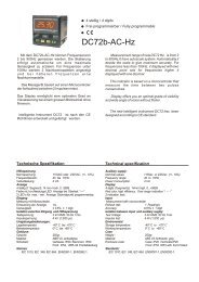
Mit dem <strong><strong>DC</strong>72b</strong>-<strong>DC</strong>-A können Ströme von<br />
-200mA bis +200mA<strong>DC</strong> gemessen werden. Der<br />
Eingangsbereich kann hierbei sinnvoll gewählt<br />
werden (5, 20 oder 200mA).<br />
Das Instrument kann einfach und intuitiv<br />
programmiert werden. Dies macht Sie schnell<br />
vertraut mit dem Instrument und lässt den<br />
erwarteten Eingangsbereich mit den grossen und<br />
zweckmässigen Fronttasten einstellen. Das<br />
Display ermöglicht eine optimalen Grad an<br />
Visualisierung bei einem grossen Blickwinkel ohne<br />
flimmern.<br />
Das neue intelligente Instrument <strong>DC</strong>72 ist nach<br />
den CE Richtlinien entwickelt und gefertigt<br />
worden.<br />
4 stellig / 4 digits<br />
Frei programmierbar / Fully programmable<br />
<strong><strong>DC</strong>72b</strong>-<strong>DC</strong>-A<br />
With the <strong>DC</strong>72 A we can measure since -<br />
200mA up to +200mA. Properly input range can be<br />
selected (5mA, 20mA or 200mA) .<br />
The instrument can be programmed easily<br />
and intuitively. This makes you familiar with the<br />
instrument and let you program required input<br />
through the big and usable front keyboard. Display<br />
offers you an optimal grade of visibility and wide<br />
angle of vision without flicker.<br />
The new intelligent instrument <strong>DC</strong>72 has been<br />
designed according to CE standard.<br />
Technische Spezifikation Technical specification<br />
Hilfsspannung<br />
Nennspannung: 115VAC oder 230VAC (+/- 10%)<br />
Frequenzbereich: 40 bis 70Hz.<br />
Verlustleistung: 4 VA<br />
Anzeige<br />
4 stellig (7 Segment), 14 mm hoch, 1999...9999<br />
Farbe rot, hochleistungs LED. Anzeige bei Überlast: “----”<br />
2 LED´s für max. - min. Anzeige. Dezimalpunkt programmierbar.<br />
Eingang<br />
Messung mit Microcontroler.<br />
Auflösung: 10 bits<br />
Umwandlungsverfahren: schrittweise Annäherung.<br />
Abtastungen pro Zyklus: 64<br />
Erneuerung der Anzeige: 1/s.<br />
Genauigkeit: : ± 0,5% ± 1 dígit<br />
Isolation zwischen Eingang und Hilfsspannung<br />
Testspannung: 3 kV RMS 50 Hz 1min.<br />
Impulsspannung: 4 kV (1.2/50 µs)<br />
Umgebungsbedienungen:<br />
Lagertemperatur: -40º C bis +70º C<br />
Betriebstemperatur: 0º C bis +65º C<br />
Gehäuse:<br />
Gewicht: 250gr.<br />
Material: ABS V0, antrazitgrau<br />
Schutzart: Gehäuse: IP20, Klemmen: IP20<br />
Front: IP54, IP65 mit Frontabdeckung<br />
Normen:<br />
IEC 1010, IEC 348, IEC 664, EN50081-1, EN50082-1.<br />
Auxiliary supply:<br />
Nominal values: 115Vac or 230Vac (+/- 10%)<br />
Frequency range: 40 to 70Hz<br />
Power Consumption : 4 VA<br />
Display:<br />
4 digits (7segments), 14mm high, 1999...9999.<br />
Red color, high efficiency. Over range indication “- - - -”<br />
2 indication leds. Decimal point programmable.<br />
Input:<br />
Measurement with microcontroler<br />
Measurement resolution : 10 bits<br />
Conversion technique: successive approximations<br />
Number of samples for cycle: 64<br />
Refresh rate: 1 Reading/s<br />
Accuracy: ±0’5% ± 1 digit<br />
Isolation between input and auxiliary supply:<br />
Test Voltage: 3 kV RMS 50 Hz 1min<br />
Impulse test: 4 kV (1.2/50 µs)<br />
Enviromental:<br />
Storage temperature: -40º C to +70º C<br />
Working temperature: 0º C to +65º C<br />
Case:<br />
Weight : 250gr.<br />
Material: ABS V0 Anthracite grey<br />
Enclosure code: Case: IP20, Terminals:IP20<br />
Front: IP54 IP65 with front Protect.<br />
Standards:<br />
IEC 1010, IEC 348, IEC 664, EN50081-1, EN50082-1.
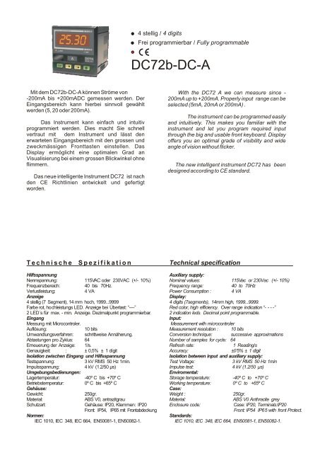
Konfiguration<br />
Das Instrument ist werkseitig auf den Messbereich 200mA<br />
eingestellt.<br />
Der Messbereich beim <strong>DC</strong>72 wird über einen internen<br />
Jumper eingestellt, die einzelnen Schritte sind:<br />
1.- Alle Leitungen müssen abgeklemmt sein. Die<br />
Schnappbefestigung der Rückwand mit einem<br />
Schraubenzieher oder ähnlichen Werkzeug niederdrücken<br />
um das Gehäuse zu Öffnen. (Abbildung 1)<br />
2.- Das Gerät vorsichtig aus dem Gehäuse herausziehen.<br />
(Abbildung 2)<br />
3.- Jumper je nach Messbereich in eine der drei Positionen<br />
stecken. (Abbildung 3)<br />
4.- Danach das Gerät wieder in das Gehäuse schieben,<br />
anschliessen und mit der Programmierung fortfahren.<br />
Abbildung 1 Abbildung 2 Abbildung 3<br />
Programmierung Programation<br />
Die Programmierung des Instruments wird in einer<br />
Baumstruktur durchgeführt:<br />
02O O Einstellung des Messbereichs, gleich wie Jumper.<br />
The instrument configuration can be carried out in a<br />
logical mode through a tree-type menu:<br />
02OO<br />
Indicate here the Measurement range.<br />
(200mA, 20mA oder 5mA)<br />
P Decimal point: Set here the required position of<br />
P Dezimalpunkt: Einstellung des Dezimalpunktes bei the decimal point when the measurement is displayed on<br />
Anzeige des Messwerts.<br />
screen.<br />
Definition der Wertepaare. Eingabe Messwert (In- X).<br />
Determination of the measuring row with 2 point-<br />
Eingabe des dazugehörigen Anzeigewert (ds - X).<br />
pairs. Enter then the measuring value (In-X)and following<br />
Um Stelle auszuwähen Taste drücken:<br />
the value to be visualized on screen (ds- X).<br />
Um Wert zu Ändern Taste drücken:<br />
To cyclically move along the four digits press the key<br />
To modify the value of the selected digit repeatedly press<br />
the key<br />
Funktion der Tasten Keyboard functions<br />
Configuration <strong><strong>DC</strong>72b</strong>-<strong>DC</strong>-A<br />
The instrument is factory shipped for the use of a 200mA.<br />
Range.<br />
The measurement range configuration of the Dc72 is<br />
donned with the on-board jumper. Steps to be followed<br />
are:<br />
1.- Insure that no incoming wire is connected to the<br />
instrument. Press the case holding piece with a<br />
screwdriver or a similar tool in order to release the base<br />
from the rest of the case.(figure1)<br />
2.- Remove the set composed by the base and circuits by<br />
pulling the base and carefully sliding it out.(figure2)<br />
3.- Locate the jumper and range configuration select with<br />
one to three possible positions.(figure3)<br />
4.- Once these closed and connected, the measurement<br />
range team with the configuration menu.<br />
Set Programmierung: Taste drücken um in<br />
Set Setup option: Pressing this key setup menus are<br />
Konfigurationmodus zu gelangen..<br />
accessed for user-configuration actions. Once within the<br />
Min.-Max. Werte: Taste drücken um Min.- und Max.<br />
Werte anzuzeigen.<br />
setup menus, use this key to validate choices and<br />
modifications.<br />
Löschen der Min.-Max. Werte. Taste drücken um<br />
gespeicherte Min.-Max. Werte zu löschen. Min.-Max Werte<br />
Peak and Valley: Pressing this key the maximum<br />
and minimum values monitored are displayed.<br />
werden beim Ausschalten der Hilfsspannung gelöscht.<br />
Erasure Peak and Valley values. Also can be<br />
achieved taking the auxiliary supply.<br />
Set<br />
0<br />
Set<br />
450009C03<br />
C F 02<br />
O<br />
Set<br />
P<br />
00<br />
002O 0005<br />
02 O O.<br />
Set<br />
00<br />
O<br />
Set<br />
5<br />
0<br />
00<br />
O<br />
Set<br />
2<br />
02<br />
O<br />
Set<br />
5 2<br />
02<br />
O<br />
Set<br />
66.00<br />
72.00<br />
66.00<br />
Brida de sujección<br />
Fixing clamps<br />
72.00<br />
Jumper<br />
85.5<br />
68.00<br />
Panel Hole<br />
Panel cut-out<br />
ES 1:200mA.<br />
ES 2: 20mA<br />
ES 3:5mA<br />
5.00<br />
68.00