Pneumatische Expansionsspannwellen Pneumatic expanding shaft
Pneumatische Expansionsspannwellen Pneumatic expanding shaft
Pneumatische Expansionsspannwellen Pneumatic expanding shaft

Erfolgreiche ePaper selbst erstellen
Machen Sie aus Ihren PDF Publikationen ein blätterbares Flipbook mit unserer einzigartigen Google optimierten e-Paper Software.
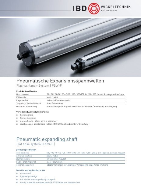
<strong>Pneumatische</strong> <strong>Expansionsspannwellen</strong><br />
Flachschlauch-System ( PSW-F )<br />
Produkt Spezifikation<br />
Durchmesser<br />
Füllventile<br />
Lagerzapfen<br />
Tragrohr/- Wellen Material<br />
Optionale Ausstattung<br />
50 / 70 / 70-76,2 / 76 /100 / 120 / 150-152,4 / 200 - 203,2 mm / Sondergr. auf Anfrage<br />
axial / radial<br />
frei nach Kundenwunsch<br />
Stahl / Aluminium<br />
Aufsteckadapter für größere Hülsendurchmesser / Maßskala / Anschlagring<br />
Vorteile und Anwendungsbereiche<br />
kostengünstig<br />
leichte Bauweise<br />
auch schmale Hülsen perfekt spannbar<br />
ideal geeignet bei standard Hülsen (Ø 70-200mm) und mittlerer Belastung<br />
<strong>Pneumatic</strong> <strong>expanding</strong> <strong>shaft</strong><br />
Flat hose system ( PSW-F )<br />
product specification<br />
core diameter<br />
air valve position<br />
journal design<br />
body/- <strong>shaft</strong> material<br />
optional equipment<br />
50 / 70 / 70-76,2 / 76 /100 / 120 / 150-152,4 / 200 - 203,2 mm / Special sizes on request<br />
axial / radial<br />
on customer request<br />
steel / aluminum<br />
adapter for larger core diameter / measuring scale / stop limit ring<br />
Benefits and application areas<br />
economical<br />
lightweight design<br />
too narrow sleeves perfectly clamped<br />
ideally suited for standard tubes (Ø 70-200mm) and medium load
3<br />
4<br />
5<br />
1<br />
2<br />
9<br />
10<br />
8<br />
6<br />
7<br />
1. Füllventil Valve<br />
2. Klemmstück Oberteil Clamping piece top part<br />
3. Spannleiste Gripping row / leaf<br />
4. Schutzband Protecting tape<br />
5. Flachschlauch Rubber flat tube<br />
6. Lagerzapfen mit Luftanschluß Journal with air supply<br />
7. Rückhaltefeder Spring<br />
8. Tragrohr Body<br />
9. Klemmstück Unterteil Clamping piece bottom part<br />
10. Lagerzapfen ohne Luftanschluß Journal without air supply<br />
IBD WICKELTECHNIK GMBH · BÖLLINGSHÖFEN 79 · D-32549 BAD OEYNHAUSEN · FON +49 5734 9602 - 0 · MAIL: IBD@IBD-WT.COM · WEB: WWW.IBD-WT.DE
<strong>Pneumatische</strong> <strong>Expansionsspannwellen</strong><br />
Zentrumschlauch-System ( PSW-Z )<br />
Produkt Spezifikation<br />
Durchmesser<br />
Füllventile<br />
Lagerzapfen<br />
Tragrohr/- Wellen Material<br />
Optionale Ausstattung<br />
50 / 70 / 70-76,2 / 76 /100 / 120 / 150-152,4 / 200 - 203,2 mm / Sondergr. auf Anfrage<br />
axial / radial<br />
frei nach Kundenwunsch<br />
Stahl / Aluminium<br />
Aufsteckadapter für größere Hülsendurchmesser / Maßskala / Anschlagring<br />
Vorteile und Anwendungsbereiche<br />
hohe Drehzahlen möglich<br />
langlebig durch stabile Bauweise<br />
hohes Drehmoment<br />
ideal für schwere Materialrollen und hohe Drehzahlen<br />
<strong>Pneumatic</strong> <strong>expanding</strong> <strong>shaft</strong><br />
Central hose system ( PSW-Z )<br />
product specification<br />
core diameter<br />
air valve position<br />
journal design<br />
body/- <strong>shaft</strong> material<br />
optional equipment<br />
50 / 70 / 70-76,2 / 76 /100 / 120 / 150-152,4 / 200 - 203,2 mm / Special sizes on request<br />
axial / radial<br />
on customer request<br />
steel / aluminum<br />
adapter for larger core diameter / measuring scale / stop limit ring<br />
Benefits and application areas<br />
high speeds possible<br />
durable solid construction<br />
high torque<br />
ideal for heavy rolls of material and high speeds
5<br />
4<br />
2<br />
3<br />
1<br />
7<br />
6<br />
1. Lagerzapfen mit Luftanschluß Journal with air supply<br />
2. Füllventil Valve<br />
3. Expansionsdruckstück Clamping piece<br />
4. Stützrohr Support tube<br />
5. Gummischlauch Rubber tube<br />
6. Tragrohr Body<br />
7. Lagerzapfen ohne Luftanschluß Journal without air supply<br />
IBD WICKELTECHNIK GMBH · BÖLLINGSHÖFEN 79 · D-32549 BAD OEYNHAUSEN · FON +49 5734 9602 - 0 · MAIL: IBD@IBD-WT.COM · WEB: WWW.IBD-WT.DE
Pneumo-mechanische <strong>Expansionsspannwellen</strong><br />
Zentrisch spannend ( PMS )<br />
Produkt Spezifikation<br />
Durchmesser<br />
Füllventile<br />
Lagerzapfen<br />
Tragrohr/- Wellen Material<br />
Optionale Ausstattung<br />
70 / 76 /100 / 120 / 150-152,4 / 200 - 203,2 mm / Sondergrößen auf Anfrage<br />
axial / radial<br />
frei nach Kundenwunsch<br />
Stahl / Aluminium<br />
Aufsteckadapter für größere Hülsendurchmesser / Maßskala / Anschlagring<br />
Vorteile und Anwendungsbereiche<br />
auf Wunsch dynamisch gewuchtet<br />
hohe Rundlaufgenauigkeit<br />
besonders präzises Spannen<br />
ideal für sehr hohe Geschwindigkeiten<br />
Pneumo-mechanical <strong>expanding</strong> <strong>shaft</strong><br />
Centric clamping ( PMS )<br />
product specification<br />
core diameter<br />
air valve position<br />
journal design<br />
body/- <strong>shaft</strong> material<br />
optional equipment<br />
70 / 76 /100 / 120 / 150-152,4 / 200 - 203,2 mm / Special sizes on request<br />
axial / radial<br />
on customer request<br />
steel / aluminum<br />
adapter for larger core diameter / measuring scale / stop limit ring<br />
Benefits and application areas<br />
on request dynamically balanced<br />
high concentricity<br />
very precise clamping<br />
ideal for very high speeds
8<br />
7<br />
6<br />
3<br />
4<br />
5<br />
1<br />
2<br />
1. Lagerzapfen Journal<br />
2. Füllventil Valve<br />
3. Druckfeder Spring<br />
4. Keilführung Wedge guide<br />
5. Spannkeil-Unterteil Clamping wedge bottom part<br />
6. Zylinder Cylinder<br />
7. Spannkeil-Oberteil Clamping wedge upper part<br />
8. Tragrohr Body<br />
IBD WICKELTECHNIK GMBH · BÖLLINGSHÖFEN 79 · D-32549 BAD OEYNHAUSEN · FON +49 5734 9602 - 0 · MAIL: IBD@IBD-WT.COM · WEB: WWW.IBD-WT.DE
ØD<br />
Ød<br />
Spannwellen Adapter<br />
Reifenadapter<br />
Unsere Reifenadapter kommen zum Einsatz wenn kurzfristig größere Hülsen verwendet werden, für die keine<br />
passende Spannwelle vorhanden ist.<br />
Die Adapter können bequem auf die Spannwelle aufgesteckt und dort verklemmt werden. Beide Adapter<br />
verfügen über eine axiale Luftzufuhr und können mit einem Spiralschlauch verbunden werden.<br />
Clamping Shaft Adapter<br />
Collar adapter<br />
Our clamping <strong>shaft</strong> adapter will be used to clamp cores with a bigger innerdiameter for which you didn´t have<br />
a compatible air <strong>shaft</strong>.<br />
The adapter can be mounted on the <strong>shaft</strong> very easy. Both adapter can be connected together with a spiral tube<br />
by axial bypass valves.<br />
HülseninnenØ AußenØ (ØD) InnenØ (Ød) Länge (L)<br />
core i. d.Ø outsideØ (ØD) insideØ (Ød) length (L)<br />
76 74 40 147<br />
100 98 50 147<br />
120 118 75 157<br />
125 123 75 157<br />
150 148 80 165<br />
200 198 100 185<br />
250 248 100 185<br />
300 298 150 195<br />
L
Für individuelle Sonderlösungen bieten wir<br />
alternativ Hohlspannwellen.<br />
For individual special solutions we offer<br />
also air <strong>shaft</strong>s with a compatible bore hole.<br />
5<br />
4<br />
3<br />
2<br />
1<br />
1. Klemmring Clamp ring<br />
2. Füllventil Valve<br />
3. Anschlagbund (optional) Stop collar<br />
4. Grundkörper Body<br />
5. Expansionseinheit Expansionunit<br />
IBD WICKELTECHNIK GMBH · BÖLLINGSHÖFEN 79 · D-32549 BAD OEYNHAUSEN · FON +49 5734 9602 - 0 · MAIL: IBD@IBD-WT.COM · WEB: WWW.IBD-WT.DE
Friktionswellen<br />
Pneumo- mechanisch ( MFW-K )<br />
Produkt Spezifikation<br />
Durchmesser<br />
Füllventile<br />
Lagerzapfen<br />
Tragrohr<br />
Ringbreiten<br />
50 / 70 / 76,2 / 150 /152,4 mm / Sondergrößen auf Anfrage<br />
axial / radial<br />
frei nach Kundenwunsch<br />
Stahl<br />
20 / 25 / 50 mm<br />
Friction Shaft<br />
Pneumo- mechanic ( MFW-K )<br />
product specification<br />
core diameter<br />
air valves position<br />
journal design<br />
body/- <strong>shaft</strong> material<br />
core width<br />
50 / 70 / 76,2 / 150 /152,4 mm / Special sizes on request<br />
axial / radial<br />
on customer request<br />
steel<br />
20 / 25 / 50 mm<br />
Optimales Wickelergebnis auch bei<br />
unterschiedlichen Rollendurchmessern.<br />
Optimized winding results also for<br />
different coil diameters
6<br />
5<br />
4<br />
3<br />
2<br />
1<br />
7<br />
8<br />
9<br />
1. Klemmring Clamping ring<br />
2. Lagerzapfen Journal with air supply<br />
3. Friktionsleiste Friction flat rod<br />
4. Flachschlauch Rubber flat tube<br />
5. Tragwelle Body<br />
6. Lagerzapfen ohne Luftanschluss Journal without air supply<br />
7. Füllventil Valve<br />
8. Distanzring Distance ring<br />
9. Friktionsring Friction ring<br />
IBD WICKELTECHNIK GMBH · BÖLLINGSHÖFEN 79 · D-32549 BAD OEYNHAUSEN · FON +49 5734 9602 - 0 · MAIL: IBD@IBD-WT.COM · WEB: WWW.IBD-WT.DE
Wickelwellen Zubehör<br />
Füllpistole mit Manometer<br />
Füllpistole für Autoventil, Flüllpistole für Halbmondventil,<br />
Spiralschlauch mit Schnellverschluss für Füllpistolen<br />
Wellenersatzteile<br />
Ventile, Schläuche, Druckstücke, Spannleisten, O-Ringe, Distanzstücke<br />
Schutzband, Klemmringe, Schrauben, etc.<br />
Anbauteile<br />
Anschlagring, Maßskala<br />
Winding Shaft Accessories<br />
Filling pistol with manometer<br />
Filling pistol for car valve, Filling pistol for half moon valve, Gripping row/<br />
leaf, Spiral tube with quick fastener for Filling pistol<br />
Shaft parts<br />
Valves, hoses, pressure pads, O-rings, spacers, Tape,<br />
Clamping rings, screws, etc.<br />
attachments<br />
Stop limit ring, measuring scale<br />
IBD WICKELTECHNIK GMBH · BÖLLINGSHÖFEN 79 · D-32549 BAD OEYNHAUSEN · FON +49 5734 9602 - 0 · MAIL: IBD@IBD-WT.COM · WEB: WWW.IBD-WT.DE
7,5<br />
7,5<br />
G 1/4<br />
16<br />
16<br />
G 1/4<br />
9,2<br />
8<br />
SW15<br />
16,5<br />
11,5<br />
SW17<br />
26,7<br />
G 1/4<br />
10<br />
8<br />
21,5<br />
20<br />
12<br />
G 1/4<br />
Füllventile / Air valves<br />
SW12<br />
Ø14<br />
SW11<br />
8V1-1<br />
G 1/8<br />
M10x1<br />
M10x1<br />
FVT-H-R1/8 FVT-RH-M10x1 FVT-A-M10x1<br />
SW12<br />
SW19<br />
SW15<br />
M10x1<br />
G 3/8 M14x1<br />
FVT-H-M10x1 FVT-H-R3/8 FVT-H-M14x1<br />
Füllstutzen / Filler nozzle<br />
35,25<br />
34,5<br />
10<br />
9,2<br />
Füllstutzen für:<br />
Filling nozzle for:<br />
FVT-RH-M10x1<br />
FVT-H-M10x1<br />
FVT-H-M14x1<br />
FVT-H-R1/8<br />
FVT-H-R3/8<br />
Füllstutzen für:<br />
Filling nozzle for:<br />
FVT-A-M10x1<br />
150<br />
9<br />
Ø16<br />
15<br />
Verlängerung für Füllstutzen<br />
Extension for filling nozzle<br />
IBD WICKELTECHNIK GMBH · BÖLLINGSHÖFEN 79 · D-32549 BAD OEYNHAUSEN · FON +49 5734 9602 - 0 · MAIL: IBD@IBD-WT.COM · WEB: WWW.IBD-WT.DE
ZF.L<br />
ZF.R<br />
IBD SPANNWELLEN Fax: +49(0) 5734 9602 96<br />
Firma<br />
Telefon<br />
Ansprechpartner<br />
Fax<br />
Adresse<br />
Email<br />
PLZ<br />
Ort<br />
Menge:<br />
Daten zur Expansionsspannwelle Serie: PSW-F PSW-Z PMS<br />
GL.0<br />
ZL.L<br />
TL.0<br />
ZL.R<br />
1 2 3<br />
4<br />
Gewünschte Ventilposition: 1 2 3 4 Position Antrieb / Bremse: 1 4<br />
LA.0<br />
Daten zur Hülse<br />
01.0 Hülseninnendurchmesser mm<br />
02.0 Hülsentoleranz mm<br />
03.0 Hülsenaußendurchmesser mm<br />
04.0 Hülsenmaterial Pappe Stahl Kunststoff<br />
Daten zum Zapfen<br />
(L) links<br />
(R) rechts<br />
Zapfenlänge ZL. mm mm<br />
Zapfenform ZF.<br />
rund Ø mm mm<br />
vierkant mm mm<br />
dreikant mm mm<br />
Zapfenqualität ZQ normal gehärtet geschliffen<br />
Sonstiges<br />
Zapfen im Detail<br />
Daten zum Material<br />
05.0 max. Rollenbreite mm<br />
05.4 min. Rollenbreite mm<br />
06.0 Mehrfachnutzen ja nein<br />
07.0 max. Rollendurchmesser (für 05.0) mm<br />
07.4 max. Rollendurchmesser (für 05.4) mm<br />
08.0 max. Rollengewicht bei max. Breite kg<br />
08.4 max. Rollengewicht bei min. Breite kg<br />
09.0 Belastungsfall stabil labil<br />
10.0 Tragwalze ja nein<br />
11.0 Wicklung auf ab<br />
12.0 Wickelmaterial<br />
13.0 max. Drehzahl 1/min<br />
13.1 max. Geschwindigkeit m/min<br />
14.0 Notstopp sec.<br />
15.0 Bahnzug N<br />
16.0 max. Drehmoment Nm<br />
Druckstücke aus (PSW-Z ): Stahl Gummi<br />
Spannleisten aus (PSW-F): Aluminium Gummi<br />
Belastungsfall<br />
stabil<br />
fest gewickelter Ballen<br />
labil<br />
locker gewickelter Ballen
ZF.L<br />
ZF.R<br />
IBD clamping <strong>shaft</strong> Fax: +49(0) 5734 9602 96<br />
Company<br />
Phon<br />
Individual contact<br />
Fax<br />
Adress<br />
Email<br />
Postcode, City<br />
Ort<br />
quantity:<br />
Specification <strong>expanding</strong> <strong>shaft</strong> serie: PSW-F PSW-Z PMS<br />
GL.0<br />
ZL.L<br />
TL.0<br />
ZL.R<br />
1 2 3<br />
4<br />
Location of air valve: 1 2 3 4 Location of drive/brake: 1 4<br />
LA.0<br />
Core data<br />
01.0 core I.D. mm<br />
02.0 toleranz mm<br />
03.0 core O.D. mm<br />
04.0 core material paper steel plastic<br />
Journal information<br />
(L) left<br />
(R) right<br />
journal length ZL. mm mm<br />
journal design ZF.<br />
round Ø mm mm<br />
square mm mm<br />
triangular mm mm<br />
journal quality ZQ normal hardened grinded<br />
others<br />
journal detail<br />
Web data<br />
05.0 max. width mm<br />
05.4 min. width mm<br />
06.0 multiple cores yes no<br />
07.0 max. roll diameter (for 05.0) mm<br />
07.4 max. roll diameter (for 05.4) mm<br />
08.0 max. weight at max. width kg<br />
08.4 max. weight at min. width kg<br />
09.0 load scheme stable unstable<br />
10.0 drum support yes no<br />
11.0 application re- unwind<br />
12.0 web material<br />
13.0 max. rpm 1/min<br />
13.1 max. speed m/min<br />
14.0 emergency stop sec.<br />
15.0 tension N<br />
16.0 max. torque Nm<br />
Lugs made from (PSW-Z / PMS): steel rubber<br />
Leafs made from (PSW-F): alu rubber<br />
Load scheme<br />
stable loading<br />
unstable loading
ZF.L<br />
ZF.R<br />
IBD FRIKTIONSWELLE Fax: +49(0) 5734 9602 96<br />
Firma<br />
Telefon<br />
Ansprechpartner<br />
Fax<br />
Adresse<br />
Email<br />
PLZ<br />
Ort<br />
Menge:<br />
Daten zur Friktionswelle Serie MFW-K<br />
ZL.L<br />
GL.0<br />
TL.0<br />
ZL.R<br />
1 4<br />
AR<br />
LA.0<br />
AL<br />
Gewünschte Ventilposition: 1 2 Position Antrieb / Bremse: 1 4<br />
Daten zur Hülse<br />
Daten zum Material<br />
01.0 Hülseninnendurchmesser m m<br />
02.0 Hülsentoleranz m m<br />
03.0 Hülsenaußendurchmesser m m<br />
04.0 Hülsenmaterial Pappe Stahl Kunststoff<br />
Daten zum Zapfen<br />
(L) links<br />
(R) rechts<br />
Zapfenlänge ZL. mm mm<br />
Zapfenform ZF.<br />
rund Ø m m mm<br />
vierkant mm mm<br />
dreikant m m mm<br />
Zapfenqualität ZQ normal gehärtet geschliffen<br />
Sonstiges<br />
Zapfen im Detail<br />
05.0 max. Rollenbreite<br />
mm<br />
05.4 min. Rollenbreite<br />
mm<br />
06.0 Mehrfachnutzen ja nein<br />
06.1 Anzahl der Nutzen<br />
06.2 min. Nutzenbreite<br />
mm<br />
07.0 max. Rollendurchmesser (für 05.0) m m<br />
07.4 max. Rollendurchmesser (für 05.4) m m<br />
08.0 max. Rollengewicht bei max. Breite k g<br />
08.4 max. Rollengewicht bei min. Breite k g<br />
08.5 max. Gewicht je Rolle<br />
kg<br />
12.0 Wickelmaterial<br />
13.0 max. Drehzahl<br />
1/min<br />
13.1 max. Geschwindigkeit<br />
m/min<br />
15.0 Bahnzug max.<br />
N<br />
15.1 Bahnzug min.<br />
N<br />
16.0 max. Drehmoment<br />
Nm<br />
16.1 min. Drehmoment<br />
Nm<br />
16.2 max. Drehmoment pro Nutzen Nm<br />
16.3 min. Drehmoment pro Nutzen<br />
Nm
ZF.L<br />
ZF.R<br />
IBD FRICTION SHAFT Fax: +49(0) 5734 9602 96<br />
Company<br />
Phon<br />
Individual contact<br />
Fax<br />
Adress<br />
Email<br />
Postcode, City<br />
Ort<br />
quantity:<br />
cation friction <strong>shaft</strong> serie MFW-K<br />
ZL.L<br />
GL.0<br />
TL.0<br />
ZL.R<br />
1 4<br />
AR<br />
LA.0<br />
AL<br />
Location of air valve: 1 4 Location of drive/brake: 1 4<br />
Core data<br />
Web data<br />
01.0 core I.D.<br />
mm<br />
02.0 toleranz<br />
mm<br />
03.0 core O.D.<br />
mm<br />
04.0 core material paper steel plastic<br />
Journal information<br />
(L) left<br />
(R) right<br />
journal length ZL. mm mm<br />
journal design ZF.<br />
round Ø mm mm<br />
square mm mm<br />
triangular mm mm<br />
journal quality ZQ normal hardened grinded<br />
others<br />
journal detail<br />
05.0 max. width<br />
mm<br />
05.4 min. width<br />
mm<br />
06.0 multiple cores yes no<br />
06.1 number of cores<br />
06.2<br />
min. core width<br />
mm<br />
07.0 max. roll diameter (for 05.0)<br />
mm<br />
07.4 max. roll diameter (for 05.4)<br />
mm<br />
08.0 max. weight at max. width<br />
kg<br />
08.4 max. weight at min. width<br />
kg<br />
08.5 max. weight each reel<br />
kg<br />
12.0 web material<br />
13.0 max. rpm<br />
1/min<br />
13.1 max. speed<br />
m/min<br />
15.0 max. tension<br />
N<br />
15.1 min. tension<br />
N<br />
16.0 max. torque<br />
Nm<br />
16.1 min. torque<br />
Nm<br />
16.2 max. torque per cores<br />
Nm<br />
16.3 min. torque per cores<br />
Nm
<strong>Pneumatische</strong>r Expansionsspannkopf<br />
Serie PSK.ZR.F<br />
Produkt Spezifikation<br />
Durchmesser<br />
50-300 mm / Sondergrößen auf Anfrage<br />
Füllventile<br />
axial / radial<br />
Tragrohr<br />
Stahl<br />
Optional<br />
Aufsteckadapter / Zentrierflansch / Einfürkonus / Zwischenflansch<br />
Spannelemente<br />
Spannkeile oder Spannschalen<br />
Spannmethode 1. Spannen: Druckluft Entspannen: Federkraft<br />
2. Federkraft Druckluft<br />
Vorteile und Anwendungsbereiche<br />
hülsenschonend durch reibschüssiges Spannen<br />
Drehmoment unabhängiges Spannen<br />
achsloses Wickeln von Papier und Folie<br />
<strong>Pneumatic</strong> clamping chuck<br />
Serie PSK.ZR.F<br />
product specification<br />
core diameter<br />
50-500 mm / special sizes on request<br />
air valve position<br />
axial / radial<br />
body<br />
steel<br />
optional equipment<br />
adapter / centering flange / inlet guiding cone / intermediate flange<br />
clamping elements<br />
wedges or clamping shells<br />
clamping method 1. clamping: compressed air relieve pressure: spring force<br />
2. spring force compressed air<br />
Benefits and application areas<br />
eliminates core damage, prevents core slippage<br />
Independent torque tightening<br />
<strong>shaft</strong>less wrapping paper and foil
4<br />
3<br />
2<br />
1<br />
1. Keilführung wedge guide<br />
2. Spannkeil clamping wedge<br />
3. Gehäuse hausing<br />
4. Kolben piston<br />
IBD WICKELTECHNIK GMBH · BÖLLINGSHÖFEN 79 · D-32549 BAD OEYNHAUSEN · FON +49 5734 9602 - 0 · MAIL: IBD@IBD-WT.COM · WEB: WWW.IBD-WT.DE
AD<br />
LD<br />
ZD<br />
SD<br />
SD<br />
DD<br />
IBD SPANNKOPF Fax: +49(0) 5734 9602 96<br />
Firma<br />
Telefon<br />
Ansprechpartner<br />
Fax<br />
Adresse<br />
Email<br />
PLZ<br />
Ort<br />
Menge:<br />
Daten zum Spannkopf PSK.ZR.F<br />
AS<br />
FL<br />
GL<br />
DL<br />
AD<br />
LD<br />
zs+<br />
zs-<br />
Daten Material / Hülse<br />
01.0 Hülseninnendurchmesser mm<br />
02.0 Hülsentoleranz mm<br />
03.0 Hülsenaußendurchmesser mm<br />
04.0 Hülsenmaterial Pappe Stahl Kunststoff<br />
07.0 max. Rollendurchmesser mm<br />
08.0 max Rollengewicht kg<br />
10.0 Tragwalze ja nein<br />
11.0 Wicklung auf ab<br />
12.0 Wickelgut<br />
13.0 max. Drehzahl 1/min<br />
14.0 max. Drehmoment Nm<br />
15.0 Betriebsdruck bar<br />
Konstruktive Daten<br />
GL Gesamtlänge mm<br />
DL Dornlänge mm<br />
FL Flanschlänge mm<br />
DD Dornaußendurchmesser mm<br />
AD Außendurchmesser mm<br />
LD Lochkreisdurchmesser mm<br />
ZD Zentrierdurchmesser mm<br />
ZS - Zentrierflanschstärke mm<br />
SD Schraubendurchmesser mm<br />
AS Anzahl Schrauben Stück<br />
VP Ventielposition radial axial<br />
Spannen über<br />
Federkraft<br />
Druckluft
AD<br />
LD<br />
ZD<br />
SD<br />
SD<br />
DD<br />
IBD clamping chucks Fax: +49(0) 5734 9602 96<br />
Company<br />
Phon<br />
Individual contact<br />
Fax<br />
Adress<br />
Email<br />
Postcode, City<br />
Ort<br />
quantity:<br />
Specification chuck serie PSK.ZR.F<br />
AS<br />
FL<br />
GL<br />
DL<br />
AD<br />
LD<br />
zs+<br />
zs-<br />
Core and web data<br />
01.0 core I.D. mm<br />
02.0 toleranz mm<br />
03.0 core O.D. mm<br />
04.0 core material paper steel plastic<br />
07.0 max. reel diameter mm<br />
08.0 max. web weight kg<br />
10.0 drum support yes no<br />
11.0 application rewind unwind<br />
12.0 web material<br />
13.0 max. rpm 1/min<br />
14.0 max. torque Nm<br />
15.0 operating pressure bar<br />
Design data<br />
GL overall length mm<br />
DL pilot length mm<br />
FL flange length mm<br />
DD pilot O.D. mm<br />
AD outher diameter mm<br />
LD bolt circle diameter mm<br />
ZD centering diameter mm<br />
ZS - centering flange width mm<br />
SD screw diameter mm<br />
AS number of screws pc<br />
VP location of air valve radial axial<br />
<strong>expanding</strong> process by spring force<br />
compressed air
Mechanischer Expansionsspannkopf<br />
Serie MSK-S / SM<br />
Produkt Spezifikation<br />
Durchmesser<br />
Expansion<br />
Optional<br />
70 / 76,2 / 100 / 127 / 150 / 152,4 / 300 mm /Sondergrößen auf Anfrage<br />
gegen Verdrehung<br />
Wechseladapter<br />
Vorteile und Anwendungsbereiche<br />
langlebig und wartungsarm<br />
kostengünstig<br />
hülsenschonend durch reibschüssiges Spannen<br />
achsloses Wickeln<br />
Mechanical expansion chuck<br />
Serie MSK-S / SM<br />
product specification<br />
core diameter<br />
expansion<br />
optional equipment<br />
70 / 76,2 / 100 / 127 / 150 / 152,4 mm / Sondergrößen auf Anfrage<br />
torque activated<br />
adapter<br />
Benefits and application areas<br />
durable and low maintenance<br />
economical<br />
eliminates core damage, prevents core slippage<br />
<strong>shaft</strong>less winding
4<br />
3<br />
2<br />
1<br />
1. Deckel Cover plate<br />
2. Gehäuse housing<br />
3. Spannbacke Clamping piece<br />
4. Grundkörper mit Flansch Base body with flange<br />
IBD WICKELTECHNIK GMBH · BÖLLINGSHÖFEN 79 · D-32549 BAD OEYNHAUSEN · FON +49 5734 9602 - 0 · MAIL: IBD@IBD-WT.COM · WEB: WWW.IBD-WT.DE
AD<br />
LD<br />
ZD<br />
SD<br />
DD<br />
IBD SPANNKOPF Fax: +49(0) 5734 9602 96<br />
Firma<br />
Telefon<br />
Ansprechpartner<br />
Fax<br />
Adresse<br />
Email<br />
PLZ<br />
Ort<br />
Menge:<br />
Daten zum Spannkopf MSK-S und (oder) SM<br />
AS<br />
FL<br />
GL<br />
DL<br />
AD<br />
LD<br />
zszs+<br />
Daten Material / Hülse<br />
01.0 Hülseninnendurchmesser mm<br />
02.0 Hülsentoleranz mm<br />
03.0 Hülsenaußendurchmesser mm<br />
04.0 Hülsenmaterial Pappe Stahl Kunststoff<br />
07.0 max. Rollendurchmesser mm<br />
08.0 max Rollengewicht kg<br />
10.0 Tragwalze ja nein<br />
11.0 Wicklung auf ab<br />
12.0 Wickelgut<br />
13.0 max. Drehzahl 1/min<br />
14.0 max. Drehmoment Nm<br />
Konstruktive Daten<br />
GL Gesamtlänge mm<br />
DL Dornlänge mm<br />
FL Flanschlänge mm<br />
DD Dornaußendurchmesser mm<br />
AD Außendurchmesser mm<br />
LD Lochkreisdurchmesser mm<br />
ZD Zentrierdurchmesser mm<br />
ZS + Zentrierflanschstärke<br />
mm<br />
ZS - Zentrierflanschstärke mm<br />
SD Schraubendurchmesser mm<br />
AS Anzahl Schrauben Stück
AD<br />
LD<br />
ZD<br />
SD<br />
DD<br />
IBD clamping chucks Fax: +49(0) 5734 9602 96<br />
Company<br />
Phon<br />
Individual contact<br />
Fax<br />
Adress<br />
Email<br />
Postcode, City<br />
Ort<br />
quantity:<br />
Specification chuck serie MSK-S and (or) SM<br />
AS<br />
FL<br />
GL<br />
DL<br />
AD<br />
LD<br />
zszs+<br />
Core and web data<br />
01.0 core I.D. mm<br />
02.0 toleranz mm<br />
03.0 core O.D. mm<br />
04.0 core material paper steel plastic<br />
07.0 max. reel diameter mm<br />
08.0 max. web weight kg<br />
10.0 drum support yes no<br />
11.0 application rewind unwind<br />
12.0 web material<br />
13.0 max. rpm 1/min<br />
14.0 max. torque Nm<br />
Design data<br />
GL overall length mm<br />
DL pilot length mm<br />
FL flange length mm<br />
DD pilot O.D. mm<br />
AD outher diameter mm<br />
LD bolt circle diameter mm<br />
ZD centering diameter mm<br />
ZS + centering flange width<br />
mm<br />
ZS - centering flange width mm<br />
SD screw diameter mm<br />
AS number of screws pc
Mechanischer Expansionsspannkopf<br />
Serie MSK-TM<br />
Produkt Spezifikation<br />
Durchmesser<br />
Expansion<br />
Optional<br />
70 / 76,2 / 100 / 127 / 150 / 152,4 mm / Sondergrößen auf Anfrage<br />
durch axialen Druck<br />
Doppeldorn für verschiedene Hülsengrößen<br />
Vorteile und Anwendungsbereiche<br />
langlebig und wartungsarm<br />
kostengünstig<br />
hülsenschonend durch reibschüssiges Spannen<br />
achsloses Wickeln<br />
Mechanical expansion chuck<br />
Serie MSK-TM<br />
product specification<br />
core diameter<br />
expansion<br />
optional equipment<br />
70 / 76,2 / 100 / 127 / 150 / 152,4 mm / Special sizes on request<br />
by axial pressure<br />
step chuck for multiple core sizes / <strong>expanding</strong> stop for base chuck<br />
Benefits and application areas<br />
durable and low maintenance<br />
economical<br />
eliminates core damage, prevents core slippage<br />
<strong>shaft</strong>less winding
4<br />
3<br />
2<br />
1<br />
1. Gehäuse Casing<br />
2. Druckfeder Spring<br />
3. Spannkeil Clamping webge<br />
4. Keilführung Webge guide with flange<br />
IBD WICKELTECHNIK GMBH · BÖLLINGSHÖFEN 79 · D-32549 BAD OEYNHAUSEN · FON +49 5734 9602 - 0 · MAIL: IBD@IBD-WT.COM · WEB: WWW.IBD-WT.DE
AD<br />
ZD<br />
LD<br />
SD<br />
DD<br />
IBD SPANNKOPF Fax: +49(0) 5734 9602 96<br />
Firma<br />
Telefon<br />
Ansprechpartner<br />
Fax<br />
Adresse<br />
Email<br />
PLZ<br />
Ort<br />
Menge:<br />
Daten zum Spannkopf MSK-TM<br />
AS<br />
FL<br />
GL<br />
DL<br />
AD<br />
LD<br />
zszs+<br />
Daten Material / Hülse<br />
01.0 Hülseninnendurchmesser mm<br />
02.0 Hülsentoleranz mm<br />
03.0 Hülsenaußendurchmesser mm<br />
04.0 Hülsenmaterial Pappe Stahl Kunststoff<br />
07.0 max. Rollendurchmesser mm<br />
08.0 max Rollengewicht kg<br />
10.0 Tragwalze ja nein<br />
11.0 Wicklung auf ab<br />
12.0 Wickelgut<br />
13.0 max. Drehzahl 1/min<br />
14.0 max. Drehmoment Nm<br />
Konstruktive Daten<br />
GL Gesamtlänge mm<br />
DL Dornlänge mm<br />
FL Flanschlänge mm<br />
DD Dornaußendurchmesser mm<br />
AD Außendurchmesser mm<br />
LD Lochkreisdurchmesser mm<br />
ZD Zentrierdurchmesser mm<br />
ZS + Zentrierflanschstärke<br />
mm<br />
ZS - Zentrierflanschstärke mm<br />
SD Schraubendurchmesser mm<br />
AS Anzahl Schrauben Stück
AD<br />
ZD<br />
LD<br />
SD<br />
DD<br />
IBD clamping chucks Fax: +49(0) 5734 9602 96<br />
Company<br />
Phon<br />
Individual contact<br />
Fax<br />
Adress<br />
Email<br />
Postcode, City<br />
Ort<br />
quantity:<br />
Specification chuck serie MSK-TM<br />
AS<br />
FL<br />
GL<br />
DL<br />
AD<br />
LD<br />
zszs+<br />
Core and web data<br />
01.0 core I.D. mm<br />
02.0 toleranz mm<br />
03.0 core O.D. mm<br />
04.0 core material paper steel plastic<br />
07.0 max. reel diameter mm<br />
08.0 max. web weight kg<br />
10.0 drum support yes no<br />
11.0 application rewind unwind<br />
12.0 web material<br />
13.0 max. rpm 1/min<br />
14.0 max. torque Nm<br />
Design data<br />
GL overall length mm<br />
DL pilot length mm<br />
FL flange length mm<br />
DD pilot O.D. mm<br />
AD outher diameter mm<br />
LD bolt circle diameter mm<br />
ZD centering diameter mm<br />
ZS + centering flange width<br />
mm<br />
ZS - centering flange width mm<br />
SD screw diameter mm<br />
AS number of screws pc
Alu Spannkonus<br />
Type 1-12<br />
Bei sehr einfachen Anwendungen stellen die Aluminium Spannkonen eine kostengünstige Alternative<br />
zur Spannwelle da.<br />
Die Spannkonen gibt es in verschiedenen Ausführungen für Hülsendurchmesser von 50 – 330mm<br />
Alu Clamping Cones<br />
Type 1-12<br />
The clamping cones are usable for simple applications and a low-cost alternative to the pneumatic clamping<br />
<strong>shaft</strong>s.<br />
The Clamoing cones are available in different versions for core diameters of 50 - 330mm. We also manufacture<br />
special solutions on request.
Modell / model<br />
I II III<br />
IV<br />
■ 30 ■ 40<br />
Spannbereich-Ø / clamping range-Ø 80 - 95 70 - 80 70- 80 55 - 120 70 - 120<br />
d<br />
Ø 30 - 50 30 - 50 30 - 50 30 - 35 >35 - 50<br />
■ 30, 40 30, 40 30, 40 30 40<br />
D1 110 90 95 130 130<br />
D2 75 65 65 50 65<br />
L1 145 95 145 95 83<br />
L2 40 35 35 40 40<br />
L3 20 18 18 20 20<br />
g<br />
M10<br />
Modell / model<br />
V VI VII<br />
Spannbereich-Ø / clamping range-Ø 50 - 70 145 - 160 125 - 150<br />
d<br />
Ø 30 - 40 30 - 80 30 - 60<br />
■ 30 30, 40, 50 30, 40, 50<br />
D1 90 170 160<br />
D2 45 140 120<br />
L1 145 150 145<br />
L2 35<br />
L3 18<br />
g<br />
M10<br />
Modell / model<br />
VIII<br />
IX<br />
X<br />
■ 30 ■ 40<br />
Spannbereich-Ø / clamping range-Ø 30 - 120 68 - 120 120 - 180 225 - 280<br />
Ø 30 - 40 >40 - 50 30 - 70 30 - 80<br />
d<br />
■ 30 40 40, 50 40. 50<br />
D1 130 130 190 290<br />
D2 55 63 115 220<br />
L1 185 168 185 185<br />
L2 35<br />
L3 18<br />
g<br />
M10<br />
Modell / model<br />
XI XII XIII<br />
Spannbereich-Ø / clamping range-Ø 275 - 330 75 - 180 165 - 215<br />
Ø 40 - 100 30 - 50 30 - 60<br />
d<br />
■ 40, 50 30, 40 30, 40<br />
D1 340 190 225<br />
D2 270 70 160<br />
L1 185 155 185<br />
L2 35<br />
L3 18<br />
g<br />
M10<br />
ØD2<br />
d=Ø oder <br />
G<br />
L3<br />
L2<br />
L1<br />
d=Ø oder <br />
ØD1<br />
IBD WICKELTECHNIK GMBH · BÖLLINGSHÖFEN 79 · D-32549 BAD OEYNHAUSEN · FON +49 5734 9602 - 0 · MAIL: IBD@IBD-WT.COM · WEB: WWW.IBD-WT.DE
Magnetpulverbremsen und Kupplungen<br />
Unsere Magnetpulverbremsen und Kupplungen werden bereits seit über 20 Jahren hergestellt und gehören<br />
zu unseren meist getesteten und weiterentwickelten Produkten. Um auch in Zukunft ein innovatives Produkt<br />
anbieten zu können garantieren die jüngsten Überarbeitungen unserer Magnetpulverbremsen und Kupplungen<br />
ein extrem geringes Restdrehmoment.<br />
Die Funktion<br />
präzise Drehmomentkontrolle<br />
geringe Baugröße<br />
es entstehen keine Verunreinigungen<br />
geringes Restdrehmoment<br />
Aus diesen Gründen ist die Magnetpulverbremse und Kupplung für den Einsatz im Druckbereich, Flexodruck<br />
und Rotationsdruck, aber auch für den Einsatz in Bereichen mit strengen Hygieneauflagen, wie in der Lebensmittelindustrie,<br />
besonders gut geeignet. Dank des geringen Restdrehmoments ist die Bremse letztendlich<br />
überall einsetzbar, wo nur geringe Bahnzüge vorhanden sind.<br />
Magnetic Powder Brakes / Clutches<br />
The range of electromagnetic powder brakes and clutches is one of our most tried and tested products, and has<br />
been in production for over 20 years. Our brakes and clutches have been upgraded recently in order to offer an<br />
innovative product that guarantees extremely low residual torque.<br />
This range of brakes features<br />
High precision torque control<br />
Small size<br />
No pollutants produced<br />
Reduced residual torque<br />
For these reasons, they are particularly suitable for use in the printing sector, flexographic and rotogravure<br />
machines, but also in food preparation areas or locations with stringent hygiene and dust emission tolerances.<br />
They are ideal for use in the food packaging sector, on laminating or plastic film machines and all applications<br />
involving low web tension, thanks to their very low residual torque.
DAS FUNKTIONSPRINZIP<br />
Die Magnetpulverbremse besteht aus drei wesentlichen<br />
Bauteilen: Einer Magnetspule, einem Stator und einem Rotor.<br />
Sobald die Bremse mit Strom versorgt wird beginnt sich das Magnetfeld im Inneren der Bremse, im Verhältnis<br />
zur Stromspannung, zu verändern. Durch die Spannungsänderung wird die Festigkeit des speziellen Magnetpulvers<br />
zwischen Rotor und Stator beeinflusst. Die Bremswirkung entsteht, wenn zusätzlich die Magnetspule mit<br />
Strom versorgt und das Magnetpulver sich in eine feste Verbindung zwischen Rotor und Stator verändert. Sobald<br />
die Stromversorgung unterbrochen wird, wird das Magnetpulver an die Außenwand des Stators gedrück und die<br />
Bremse befindet sich im Freilauf.<br />
OPERATING PRINCIPLE<br />
The electromagnetic powder brake consists of three basic components: a coil, a stator and a rotor.<br />
When current is supplied to the brake, the magnetic field inside the coil starts to vary in proportion to the size of<br />
the current. The variations in the magnetic field alter the viscosity of the special powder positioned between the<br />
rotor and the stator. When an electrical current is applied to the coil, the particles are aligned along the magnetic<br />
field force lines, creating a dragging bond between the rotor and the stator, thereby generating the braking<br />
effect. When the current is disconnected, the powder is pushed against the stator by the centrifugal force, thus<br />
releasing the rotor so that it can rotate.<br />
Durch das Magnetfeld werden die Partikel des<br />
Magnetpulvers miteinander verbunden und<br />
bilden eine Verbindung zwischen Stator und<br />
Rotor.<br />
The particles aligned along the magnetic field<br />
force lines create a dragging bond between the<br />
rotor and the stator.<br />
Magnetspule<br />
coil<br />
Rotor<br />
rotor<br />
Stator<br />
stator<br />
Wenn das Magnetfeld ausgeschaltet ist,<br />
werden die Partikel durch die Zentrifugalkraft<br />
an die Außenwand des Stators gedrückt.<br />
When this magnetic field is removed, the<br />
particles are pushed towards the stator by<br />
the centrifugal force.<br />
IBD WICKELTECHNIK GMBH · BÖLLINGSHÖFEN 79 · D-32549 BAD OEYNHAUSEN · FON +49 5734 9602 - 0 · MAIL: IBD@IBD-WT.COM · WEB: WWW.IBD-WT.DE
Serie B.121<br />
B.121<br />
Bremse<br />
brake<br />
B.121.R<br />
Bremse mit Radiator<br />
brake with radiator<br />
B.121.V<br />
Bremse mit Lüfter<br />
brake with fan<br />
60°<br />
4D10<br />
Drei Gewindebohrungen M5<br />
zur Befestigung. ACHTUNG:<br />
Vor einsetzen der Schraube<br />
bitte Gewinde entfernen<br />
mit Bohrer ø 5,5<br />
3 housings for screws M5 for<br />
fastening. ATTENTION: before<br />
inserting the screw remove the<br />
thread with a drill ø 5,5<br />
16.3 +0.1<br />
0<br />
M5<br />
4<br />
49<br />
Ø9<br />
4<br />
Ø55h7<br />
Ø200<br />
M5<br />
11<br />
61<br />
67<br />
Anschluss für<br />
Lüfter<br />
Fan supply<br />
Anschluss<br />
für Bremse<br />
Brake supply<br />
60°<br />
Ø103<br />
Ø115<br />
Ø158<br />
Ø182<br />
Dichtschraube<br />
mit Kabelauslass<br />
Press gland<br />
with cable<br />
Ø15H7<br />
4<br />
49<br />
48<br />
10.5<br />
128<br />
7<br />
C.121<br />
Kupplung<br />
clutch<br />
58<br />
44<br />
93.5<br />
13<br />
28.5<br />
20.5<br />
60°<br />
Drei Gewindebohrungen<br />
M5 zur Befestigung<br />
No. 3 threaded holes<br />
M5 for fastening<br />
32<br />
Ø5<br />
Ø5<br />
9<br />
4D10<br />
60°<br />
16.3 +0.1<br />
0<br />
Ø55h7<br />
25<br />
Ø15H7<br />
Ø115<br />
4<br />
49<br />
58<br />
Ø103<br />
Max. Drehmoment / Torque<br />
12 Nm<br />
Restdrehmoment / Residual torque<br />
0,06 Nm<br />
Max. Stromaufnahme / Max. current<br />
1 A<br />
Widerstand bei 20 °C / Resistance at 20 °C<br />
24 Ohm<br />
Spannung / Tension<br />
24 V (PWM)<br />
Verlustleistung / Power dissipation<br />
80 W<br />
Verlustleistung mit Radiator / Power dissipation with radiator<br />
160 W<br />
Verlustleistung mit Lüfter / Power dissipation with fan<br />
1350 W<br />
Verlustleistung der Kupplung bei 500 U/min. /<br />
Power dissipation of the clutch at 500 RPM<br />
140 W<br />
mit Radiator bei 500 U/min. / with radiator at 500 RPM<br />
400 W<br />
Verlustleistung der Kupplung bei 1000 U/min. /<br />
Power dissipation of the clutch at 1000 RPM<br />
180 W<br />
mit Radiator bei 1000 U/min. / with radiator at 1000 RPM<br />
560 W<br />
U/min. min.-max. / RPM min-max 40-2000<br />
Max. Arbeitstemperatur / Max. working temperature 70 °C<br />
Gewicht kg / Weight kg 2,5 (B.121)/4,5 (B.121.R)/3,7 (B.121.V)/3 (C.121)/5 (C.121.R)<br />
Drehmoment Nm / Torque Nm<br />
16<br />
14<br />
12<br />
10<br />
8<br />
6<br />
4<br />
2<br />
0<br />
0 0,1 0,2 0,3 0,4 0,5 0,6 0,7 0,8 0,9 1<br />
Stromaufnahme A /<br />
Current A
Serie B.351<br />
B.351<br />
Bremse<br />
brake<br />
B.351.R<br />
Bremse mit Radiator<br />
brake with radiator<br />
B.351.V<br />
Bremse mit Lüfter<br />
brake with fan<br />
60°<br />
Drei Gewindebohrungen M5<br />
zur Befestigung. ACHTUNG:<br />
Vor einsetzen der Schraube<br />
bitte Gewinde entfernen<br />
mit Bohrer ø 5,5<br />
3 housings for screws M5 for<br />
fastening. ATTENTION: before<br />
inserting the screw remove the<br />
thread with a drill ø 5,5<br />
M5<br />
54 125.5<br />
54<br />
9<br />
Ø9<br />
7<br />
M5<br />
5 D10<br />
19.3 +0.1<br />
0<br />
3 3<br />
60°<br />
Ø122<br />
Ø135.5<br />
1.5<br />
51<br />
1.5<br />
Ø55 h7<br />
Ø240<br />
Ø158<br />
Ø182<br />
Ø17H7<br />
Anschluss für<br />
Lüfter<br />
Fan supply<br />
Dichtschraube mit<br />
Kabelauslass<br />
Press gland<br />
with cable<br />
3<br />
59<br />
Anschluss für Bremse<br />
Brake supply<br />
67<br />
60<br />
8<br />
C.351<br />
Kupplung<br />
clutch<br />
58<br />
44<br />
101.5<br />
13<br />
28.5<br />
20.5<br />
60°<br />
Drei Gewindebohrungen<br />
M5 zur Befestigung<br />
No. 3 threaded holes<br />
M5 for fastening<br />
32<br />
Ø5<br />
Ø5<br />
9<br />
25<br />
60°<br />
5 D10<br />
19.3 +0.1<br />
Ø55h7<br />
0<br />
Ø17H7<br />
Ø135.5<br />
3<br />
Ø122<br />
54<br />
65.5<br />
Max. Drehmoment / Torque<br />
35 Nm<br />
Restdrehmoment / Residual torque<br />
0,2 Nm<br />
Max. Stromaufnahme / Max. current<br />
1 A<br />
Wiederstand bei 20 °C / Resistance at 20 °C<br />
24 Ohm<br />
Spannung / Tension<br />
24 V (PWM)<br />
Verlustleistung / Power dissipation<br />
130 W<br />
Verlustleistung mit Radiator / Power dissipation with radiator<br />
230 W<br />
Verlustleistung mit Lüfter / Power dissipation with fan<br />
500 W<br />
Verlustleistung der Kupplung bei 500 U/min. /<br />
Power dissipation of the clutch at 500 RPM<br />
208 W<br />
mit Radiator bei 500 U/min. / with radiator at 500 RPM<br />
650 W<br />
Verlustleistung der Kupplung bei 1000 U/min.<br />
Power dissipation of the clutch at 1000 RPM<br />
260W<br />
mit Radiator bei 1000 U/min. / with radiator at 1000 RPM<br />
810 W<br />
U/min. min.-max. / RPM min-max 40-2000<br />
Max. Arbeitstemperatur / Max. working temperature 70 °C<br />
Gewicht kg / Weight kg 4 (B.351)/7 (B.351.R)/5,2 (B.351.V)/4,6 (C.351)/7,6 (C.351.R)<br />
Drehmoment Nm / Torque Nm<br />
40<br />
35<br />
30<br />
25<br />
20<br />
15<br />
10<br />
5<br />
0<br />
0 0,1 0,2 0,3 0,4 0,5 0,6 0,7 0,8 0,9 1<br />
Stromaufnahme A / Current A<br />
IBD WICKELTECHNIK GMBH · BÖLLINGSHÖFEN 79 · D-32549 BAD OEYNHAUSEN · FON +49 5734 9602 - 0 · MAIL: IBD@IBD-WT.COM · WEB: WWW.IBD-WT.DE
Serie B.651<br />
B.651<br />
Bremse<br />
brake<br />
B.651.R<br />
Bremse mit Radiator<br />
brake with radiator<br />
B.651.V<br />
Bremse mit Lüfter<br />
brake with fan<br />
60°<br />
Drei Gewindebohrungen M5<br />
zur Befestigung. ACHTUNG:<br />
Vor einsetzen der Schraube<br />
bitte Gewinde entfernen<br />
mit Bohrer ø 5,5<br />
3 housings for screws M5 for<br />
fastening. ATTENTION: before<br />
inserting the screw remove the<br />
thread with a drill ø 5,5<br />
66<br />
4<br />
64<br />
135<br />
Anschluss für<br />
Bremse<br />
Brake supply<br />
7<br />
6D10<br />
22.8 +0.1<br />
0<br />
M5<br />
5 5<br />
Ø9<br />
M5<br />
Anschluss für<br />
Lüfter<br />
Fan supply<br />
60°<br />
Ø144<br />
Ø157<br />
1<br />
64 1<br />
Ø75h7<br />
Ø278<br />
Ø185<br />
Ø20H7<br />
Dichtschraube<br />
mit Kabelauslass<br />
Press gland<br />
with cable<br />
13 122<br />
64 8,5<br />
C.651<br />
Kupplung<br />
clutch<br />
Ø5<br />
58<br />
44<br />
Ø5<br />
110.5<br />
14<br />
29.5<br />
21.5<br />
25<br />
60°<br />
6D10<br />
22.8 +0.1<br />
0<br />
Drei<br />
Gewindebohrungen<br />
M5 zur Befestigung<br />
No. 3 threaded<br />
holes M5 for<br />
fastening<br />
32<br />
Ø75h7<br />
9<br />
60°<br />
Ø20H7<br />
Ø157<br />
4<br />
64<br />
74<br />
Ø144<br />
Max. Drehmoment / Torque<br />
65 Nm<br />
Restdrehmoment / Residual torque<br />
0,4 Nm<br />
Max. Stromaufnahme / Max. current<br />
1 A<br />
Widerstand bei 20 °C / Resistance at 20 °C<br />
24 Ohm<br />
Spannung / Tension<br />
24 V (PWM)<br />
Verlustleistung / Power dissipation<br />
170 W<br />
Verlustleistung mit Radiator / Power dissipation with radiator<br />
400 W<br />
Verlustleistung mit Lüfter / Power dissipation with fan<br />
800 W<br />
Verlustleistung der Kupplung bei 500 U/min. /<br />
Power dissipation of the clutch at 500 RPM<br />
280 W<br />
mit Radiator bei 500 U/min. / with radiator at 500 RPM<br />
950 W<br />
Verlustleistung der Kupplung bei 1000 U/min. /<br />
Power dissipation of the clutch at 1000 RPM<br />
350 W<br />
mit Radiator bei 1000 U/min. / with radiator at 1000 RPM<br />
1200 W<br />
U/min. min.-max. / RPM min-max 40-2000<br />
Max. Arbeitstemperatur / Max. working temperature 70 °C<br />
Gewicht kg / Weight kg<br />
6,5 (B.651) / 9 (B.651.R) / 8,8 (B.651.V)<br />
9,4 (C.651) / 9,4 (C.651.R)<br />
Drehmoment Nm / Torque Nm<br />
80<br />
70<br />
60<br />
50<br />
40<br />
30<br />
20<br />
10<br />
0<br />
0 0,1 0,2 0,3 0,4 0,5 0,6 0,7 0,8 0,9 1<br />
Stromaufnahme A / Current A
Serie B.1201<br />
B.1201<br />
Bremse<br />
brake<br />
B.1201.R<br />
Bremse mit Radiator<br />
brake with radiator<br />
B.1201.V<br />
Bremse mit Lüfter<br />
brake with fan<br />
73<br />
2.5 2.5<br />
219<br />
45°<br />
Vier Gewindebohrungen M6<br />
zur Befestigung<br />
No. 4 housings for screws M6<br />
for fastening<br />
6<br />
Anschluss für Bremse<br />
Brake supply<br />
Ø7<br />
Ø13<br />
Ø7<br />
45°<br />
10 D10<br />
31.3 +0.1<br />
0<br />
Ø233<br />
Ø254<br />
Ø214<br />
2<br />
69 2<br />
Ø99 h7<br />
Ø195<br />
Ø390<br />
2<br />
69<br />
Ø284<br />
Ø28 H7<br />
Anschluss für<br />
Lüfter<br />
Dichtschraube<br />
mit Kabelauslass<br />
Press gland<br />
with cable<br />
3<br />
5<br />
2.5<br />
13.5<br />
143.5<br />
Fan supply<br />
62<br />
7.5 58 7.5<br />
C.1201<br />
Kupplung<br />
clutch<br />
58<br />
44<br />
70.5 14 29.5<br />
Vier Gewindebohrungen<br />
M6 zur Befestigung<br />
No. 4 threaded holes<br />
M6 for fastening<br />
21.5<br />
10 D10<br />
32<br />
Ø5<br />
Ø5<br />
Ø214 g6<br />
Ø99 h7<br />
2<br />
69<br />
9<br />
25<br />
31.3 +0.1<br />
0<br />
Ø28 H7<br />
Ø254<br />
7.5<br />
58 5<br />
84.5<br />
121<br />
Ø233<br />
Max. Drehmoment / Torque<br />
120 Nm<br />
Restdrehmoment / Residual torque<br />
0,5 Nm<br />
Max. Stromaufnahme / Max. current<br />
1 A<br />
Widerstand bei 20 °C / Resistance at 20 °C<br />
24 Ohm<br />
Spannung / Tension<br />
24 V (PWM)<br />
Verlustleistung / Power dissipation<br />
330 W<br />
Verlustleistung mit Radiator / Power dissipation with radiator<br />
650 W<br />
Verlustleistung mit Lüfter / Power dissipation with fan<br />
1600 W<br />
Verlustleistung der Kupplung bei 500 U/min. /<br />
Power dissipation of the clutch at 500 RPM<br />
650 W<br />
mit Radiator bei 500 U/min. / with radiator at 500 RPM<br />
1440 W<br />
Verlustleistung der Kupplung bei 1000 U/min. /<br />
Power dissipation of the clutch at 1000 RPM<br />
820 W<br />
mit Radiator bei 1000 U/min. / with radiator at 1000 RPM<br />
1800 W<br />
U/min. min.-max. / RPM min-max 40-2000<br />
Max. Arbeitstemperatur / Max. working temperature 70 °C<br />
Gewicht kg / Weight kg<br />
16,5 (B.1201) / 19 (B.1201.R) / 19 (B.1201.V)<br />
17 (C.1201) / 19,5 (C.1201.R)<br />
Drehmoment Nm / Torque Nm<br />
140<br />
120<br />
100<br />
80<br />
60<br />
40<br />
20<br />
0<br />
0 0,1 0,2 0,3 0,4 0,5 0,6 0,7 0,8 0,9 1<br />
Stromaufnahme A / Current A<br />
IBD WICKELTECHNIK GMBH · BÖLLINGSHÖFEN 79 · D-32549 BAD OEYNHAUSEN · FON +49 5734 9602 - 0 · MAIL: IBD@IBD-WT.COM · WEB: WWW.IBD-WT.DE
Serie B.1701<br />
B.1701<br />
Bremse<br />
brake<br />
B.1701.R<br />
Bremse mit Radiator<br />
brake with radiator<br />
89<br />
2.5 2.5<br />
B.1701.V<br />
Bremse mit Lüfter<br />
brake with fan<br />
235<br />
45°<br />
Vier Gewindebohrungen<br />
M6 zur Befestigung<br />
No. 4 housings for screws M6<br />
for fastening<br />
2.5<br />
Anschluss für Bremse<br />
Brake supply<br />
Ø7<br />
Ø13<br />
Ø7<br />
45°<br />
M6<br />
10D10<br />
31.3 +0.1<br />
0<br />
M6<br />
Dichtschraube<br />
mit Kabelauslass<br />
Press gland<br />
with cable<br />
Ø233<br />
Ø254<br />
Ø214 g6<br />
1.5<br />
86<br />
1.5<br />
Ø99 h7<br />
Ø195<br />
Ø390<br />
1.5<br />
86<br />
Ø284<br />
Ø28H7<br />
M6<br />
M6<br />
2<br />
Anschluss<br />
für Lüfter<br />
Fan supply<br />
7.5<br />
29.5 143.5<br />
62<br />
5<br />
7.5<br />
74 7.5<br />
C.1701<br />
Kupplung<br />
clutch<br />
58<br />
44<br />
86.5<br />
14 29.5<br />
45°<br />
Vier Gewindebohrungen<br />
M6 zur Befestigung<br />
No. 4 threaded holes<br />
M6 for fastening<br />
Ø7<br />
21.5<br />
Ø5<br />
Ø5<br />
25<br />
45°<br />
10D10<br />
31.3+0.1<br />
0<br />
32<br />
Ø214 g6<br />
Ø99 h7<br />
1.5<br />
86<br />
9<br />
Ø28H7<br />
2<br />
7.5<br />
74<br />
5<br />
Ø254<br />
5<br />
100.5<br />
137<br />
Ø233<br />
Max. Drehmoment / Torque<br />
170 Nm<br />
Restdrehmoment / Residual torque<br />
0,5 Nm<br />
Max. Stromaufnahme / Max. current<br />
1 A<br />
Widerstand bei 20 °C / Resistance at 20 °C<br />
24 Ohm<br />
Spannung / Tension<br />
24 V (PWM)<br />
Verlustleistung / Power dissipation<br />
450 W<br />
Verlustleistung mit Radiator / Power dissipation with radiator<br />
850 W<br />
Verlustleistung mit Lüfter / Power dissipation with fan<br />
1500 W<br />
Verlustleistung der Kupplung bei 500 U/min. /<br />
Power dissipation of the clutch at 500 RPM<br />
760 W<br />
mit Radiator bei 500 U/min. / with radiator at 500 RPM<br />
1550 W<br />
Verlustleistung der Kupplung bei 1000 U/min. /<br />
Power dissipation of the clutch at 1000 RPM<br />
950 W<br />
mit Radiator bei 1000 U/min. / with radiator at 1000 RPM<br />
2250 W<br />
U/min. min.-max. / RPM min-max 40-2000<br />
Max. Arbeitstemperatur / Max. working temperature 70 °C<br />
Gewicht kg / Weight kg<br />
22,5 (B.1701) / 25,5 (B.1701.R) / 25 (B.1701.V)<br />
22,9 (C.1701) / 26 (C.1701.R)<br />
Drehmoment Nm / Torque Nm<br />
180<br />
160<br />
140<br />
120<br />
100<br />
80<br />
60<br />
40<br />
20<br />
0<br />
0 0,1 0,2 0,3 0,4 0,5 0,6 0,7 0,8 0,9 1<br />
Stromaufnahme A / Current A
Serie B.2500<br />
B.2500<br />
Bremse<br />
brake<br />
B.2500.R<br />
Bremse mit Radiator<br />
brake with radiator<br />
B.2500.V<br />
Bremse mit Lüfter<br />
brake with fan<br />
100<br />
180<br />
65<br />
100<br />
45°<br />
Anschluss für Bremse<br />
Brake supply<br />
10<br />
Anschluss für Bremse<br />
Brake supply<br />
M6<br />
M6<br />
18<br />
18<br />
45°<br />
16 D10<br />
+0.2<br />
59.3<br />
0<br />
Ø267<br />
Ø286<br />
5<br />
90<br />
5<br />
Ø150 h8<br />
Ø406<br />
90<br />
131<br />
Ø315<br />
Ø55 H7<br />
Anschluss für<br />
Lüfter<br />
Fan supply<br />
Acht Gewindebohrungen<br />
M6 zur Befestigung<br />
No. 8 threaded holes M6<br />
for fastening<br />
20<br />
245<br />
10 82 8<br />
C.2500<br />
Kupplung<br />
clutch<br />
58<br />
44<br />
140<br />
14 29<br />
21<br />
45°<br />
Ø5<br />
Ø5<br />
25<br />
83.5<br />
9<br />
45°<br />
16 D10<br />
Ø150 h8<br />
59.3 +0.2<br />
0<br />
Ø55 H7<br />
Ø286<br />
10<br />
95<br />
104<br />
Acht Gewindebohrungen<br />
M6 zur Befestigung<br />
No. 8 threaded holes<br />
M6 for fastening<br />
Ø286<br />
Max. Drehmoment / Torque<br />
250 Nm<br />
Restdrehmoment / Residual torque<br />
3 Nm<br />
Max. Stromaufnahme / Max. current<br />
1 A<br />
Widerstand / Resistance<br />
25,5 Ohm<br />
Spannung / Tension<br />
24 V (PWM)<br />
Verlustleistung / Power dissipation<br />
500 W<br />
Verlustleistung mit Radiator / Power dissipation with radiator<br />
900 W<br />
Verlustleistung mit Lüfter / Power dissipation with fan<br />
2000 W<br />
Verlustleistung der Kupplung bei 500 U/min. /<br />
Power dissipation of the clutch at 500 RPM<br />
1440 W<br />
mit Radiator bei 500 U/min. / with radiator at 500 RPM<br />
1650 W<br />
Verlustleistung der Kupplung bei 1000 U/min /<br />
Power dissipation of the clutch at 1000 RPM<br />
1800 W<br />
mit Radiator bei 1000 U/min. / with radiator at 1000 RPM<br />
2400 W<br />
U/min. min.-max. / RPM min-max 40-1800<br />
Max. Arbeitstemperatur / Max. working temperature 70 °C<br />
Gewicht kg / Weight kg<br />
32 (B.2500) / 38 (B.2500.R) / 38 (B.2500.V)<br />
33 (C.2500) / 40 (C.2500.R)<br />
Drehmoment Nm /<br />
Torque Nm<br />
300<br />
250<br />
200<br />
150<br />
100<br />
50<br />
0<br />
0 0,1 0,2 0,3 0,4 0,5 0,6 0,7 0,8 0,9 1<br />
Stromaufnahme A / Current A<br />
IBD WICKELTECHNIK GMBH · BÖLLINGSHÖFEN 79 · D-32549 BAD OEYNHAUSEN · FON +49 5734 9602 - 0 · MAIL: IBD@IBD-WT.COM · WEB: WWW.IBD-WT.DE
Serie B.5000<br />
B.5000<br />
Bremse<br />
brake<br />
B.5000.R<br />
Bremse mit Radiator<br />
brake with radiator<br />
B.5000.V<br />
Bremse mit Lüfter<br />
brake with fan<br />
120<br />
270.5<br />
205.5<br />
65<br />
45°<br />
Anschluss für Bremse<br />
Brake supply<br />
28.5<br />
Anschluss für Bremse<br />
Brake supply<br />
5<br />
5<br />
45°<br />
16 D10<br />
Anschluss<br />
für Lüfter<br />
Fan supply<br />
Ø55 H7<br />
59.3 +0.2<br />
0<br />
Ø342<br />
Ø360<br />
Ø324<br />
5 110 5<br />
Ø150 h8<br />
Ø390<br />
Ø285<br />
Acht Gewindebohrungen<br />
M8 zur Befestigung<br />
No. 8 threaded holes M8<br />
or fastening<br />
5<br />
12<br />
15.5 91 13.5<br />
120<br />
C.5000<br />
Kupplung<br />
clutch<br />
58<br />
44<br />
165<br />
14 29<br />
21<br />
45°<br />
Ø5<br />
Ø5<br />
45°<br />
9<br />
Ø150 h8<br />
82<br />
25<br />
16 D10<br />
59.3<br />
+0.2<br />
0<br />
Ø55 H7<br />
Acht Gewindebohrungen<br />
M6 zur Befestigung<br />
Ø360<br />
5<br />
110<br />
No. 8 threaded holes<br />
M6 for fastening<br />
Ø342<br />
129<br />
Max. Drehmoment / Torque<br />
500 Nm<br />
Restdrehmoment / Residual torque<br />
6 Nm<br />
Max. Stromaufnahme / Max. current<br />
1 A<br />
Widerstand / Resistance<br />
25,5 Ohm<br />
Spannung / Tension<br />
24 V (PWM)<br />
Verlustleistung / Power dissipation<br />
1300 W<br />
Verlustleistung mit Radiator / Power dissipation with radiator<br />
2500 W<br />
Verlustleistung mit Lüfter / Power dissipation with fan<br />
4000 W<br />
Verlustleistung der Kupplung bei 500 U/min. /<br />
Power dissipation of the clutch at 500 RPM<br />
2800 W<br />
mit Radiator bei 500 U/min. / with radiator at 500 RPM<br />
4000 W<br />
Verlustleistung der Kupplung bei 1000 U/min. /<br />
Power dissipation of the clutch at 1000 RPM<br />
3500 W<br />
mit Radiator bei 1000 U/min. / with radiator at 1000 RPM<br />
5000 W<br />
U/min. min.-max. / RPM min-max 40-1500<br />
Max. Arbeitstemperatur / Max. working temperature 70 °C<br />
Gewicht kg / Weight kg<br />
59 (B.5000) / 62 (B.5000.R) / 62 (B.5000.V)<br />
62 (C.5000) / 65 (C.5000.R)<br />
Drehmoment Nm /<br />
Torque Nm<br />
600<br />
500<br />
400<br />
300<br />
200<br />
100<br />
0<br />
0 0,1 0,2 0,3 0,4 0,5 0,6 0,7 0,8 0,9 1<br />
Stromaufnahme A / Current A
Taurus BX & Taurus Stromregelkarte für Magnetpulverbremsen<br />
Taurus ist ein, durch einen Mikroprozessor gesteuerter, digitaler Stromregler. Die Programmierung erfolgt über drei Tasten<br />
an der Vorderseite. Der Einsatz kann in einem geschlossenen Regelkreis mit einer Bahnzugregelung (wie T-One, MW90 oder<br />
SPS), welche einen stabilen Bahnzug gewährleistet, erfolgen. Beim Einsatz in einem offenen Regelkreis (mit Ultraschallsensor,<br />
Potentiometer oder einem anderen 0-10 VDC analogem Signal) gewährleistet Taurus Drehmomentstabilität an der<br />
Bremse oder Kupplung unabhängig von Einflüssen wie Beanspruchung oder Temperatur. Zum Einsatz bei Anwendungen<br />
mit geringem Drehmoment kann die Regelkarte eine negative Stromspannung aufnehmen, um den Restmagnetismus zu<br />
beseitigen.<br />
Beide Ausführungen, Taurus und Taurus BX, sind von ihrer Baugröße klein genug um auf ein DIN Profil montiert zu werden.<br />
Die lange schmale Bauform mit dem Anschluss auf der kurzen Seite wurde so konzipiert, dass so wenig Platz wie notwendig<br />
benötigt wird.<br />
SPS<br />
Steuergerät<br />
T-one oder US.3<br />
Controller<br />
T-one or US.3<br />
0-10 Vdc<br />
PWM<br />
Potentiometer<br />
Potentiometer<br />
TAURUS (BX) Regelkarte<br />
TAURUS (BX) card<br />
Magnetpulverbremse oder<br />
Magnetpulverkupplung<br />
Electromagnetic powder<br />
brake or clutch<br />
Taurus BX & Taurus regulator for electromagnetic powder brakes<br />
Taurus is a microprocessor controlled digital current regulator that can be programmed by using the three buttons on the<br />
front of the board. It can be used with the closed loop regulation and a tension controller (such as T-one, MW90 or PLC)<br />
which guarantees web tension stability. When using an open loop (with sonar, potentiometer or any other 0-10 VDC analogical<br />
input) Taurus guarantees brake/clutch torque stability irrespective of variations in the condition of the brake (wear/temperature).<br />
The device can supply a negative output current in order to cancel any residual magnetism, and making it suitable<br />
for use in low torque applications without limitations.<br />
Both the open (Taurus) and boxed (Taurus BX) versions are small enough to be mounted on DIN guides. In particular, the<br />
long, narrow form of the Taurus, with the user interface located on the short side, has been designed to take up the minimum<br />
amount of space when mounted on a panel.
Taurus<br />
102<br />
42<br />
37,5<br />
35 20 47<br />
EN 500022 und EN 50035<br />
Fixable on DIN bar<br />
EN 50022 and EN 50035<br />
Anschlüsse<br />
Terminals<br />
6,5<br />
montierbar auf<br />
101<br />
Fixable on DIN bar<br />
EN 50022<br />
22,5<br />
120<br />
128,50<br />
1,65<br />
82<br />
12,6<br />
16<br />
Taurus BX<br />
Spannungsversorgung / Power supply 24 Vac oder/ or 24 Vdc ± 10%<br />
Sicherung / Fuse 1,6 A/F<br />
Eingang / Input 0-10 Vdc (delta min. 2 Vdc)<br />
Ausgang / Output 0-1,6 A PWM moduliert, freq. = 1,2 kHz<br />
0-1,6 A PWM modulation freq. = 1,2 kHz<br />
Leistung / Absorbed power<br />
35 W max<br />
Betriebstemperatur / Operative temperature 0-50˚ C<br />
IBD WICKELTECHNIK GMBH · BÖLLINGSHÖFEN 79 · D-32549 BAD OEYNHAUSEN · FON +49 5734 9602 - 0 · MAIL: IBD@IBD-WT.COM · WEB: WWW.IBD-WT.DE
Regelkarte FP.25 Stromregelkarte für Magnetpulverbremsen<br />
Die FP.25 Regelkarte ist ein analoger Stromregler zur präzisen Stromversorgung einer Magnetpulverbremse oder Magnetpulverkupplung.<br />
Die Regelkarte lässt sich in einen geschlossen Regelkreis integrieren um zu gewährleisten, dass der Bahnzug gleichmäßig<br />
bleibt - unabhängig von der Betriebsspannung der Bremse, der Kupplung oder von äußeren Temperatureinflüssen. Die aus<br />
der Bahnzugregelung abgeleiteten Parameter erlauben den Einsatz einer Steuerung mit Tänzerwalze.<br />
Zur Vereinfachung der Installation erfolgt der Anschluss über eine 10-polige Klemmleiste.<br />
SPS<br />
Steuergerät T-one<br />
oder US.3<br />
Controller<br />
T-one or US.3<br />
0-10 Vdc<br />
PWM<br />
Potentiometer<br />
Potentiometer<br />
FP.25 Regelkarte<br />
FP.25 card<br />
Magnetpulverbremse oder<br />
Magnetpulverkupplung<br />
Electromagnetic powder<br />
brake or clutch<br />
Board FP.25 regulator for electromagnetic powder brakes<br />
The FP.25 board is an analogue current regulator that ensures the current supplied to the electromagnetic powder brake or<br />
clutch at the correct level.<br />
It is possible to use a closed current loop in order to guarantee that the torque remains stable, irrespective of variations in<br />
the supply voltage or the brake/clutch and ambient temperatures. The derivative parameter permits to use a dancing roller<br />
system.<br />
To simplify the installation procedure, the board is equipped with a 10 poles, screw locking connector.
FP.25/1<br />
10,51 52,5<br />
120<br />
25<br />
10<br />
112<br />
N˚ 4 Ø 4,5<br />
108<br />
90<br />
FP.25/2<br />
171<br />
153<br />
FUSE<br />
120<br />
112<br />
13 2 46 58 71 9 0<br />
Sicherung<br />
10<br />
60<br />
17 80<br />
95<br />
65<br />
IBD WICKELTECHNIK GMBH · BÖLLINGSHÖFEN 79 · D-32549 BAD OEYNHAUSEN · FON +49 5734 9602 - 0 · MAIL: IBD@IBD-WT.COM · WEB: WWW.IBD-WT.DE
Scheibenbremsen<br />
Serie CX<br />
Vorteile<br />
kleine Abmessung / erleichtert die Montage<br />
geringe Kosten da kompakte Baueinheiten<br />
geringe Bremsscheibengeschwindigkeit verringert die Abnutzung der Bremsbeläge<br />
stabile Drehmomentkontrolle durch Bremsbeläge<br />
absolut zuverlässig<br />
disc brakes<br />
Serie CX<br />
Just advantages<br />
dimensionally smaller units, giving a more compact machine design<br />
reduction in price due to smaller design<br />
lower top speed minimise the wear of the linings<br />
constand controllable torque from a stable friction lining material<br />
leading to total dependability
CX 250 CX 300<br />
8 Bohrungen Ø 8,5 bei Ø 280<br />
8 holes Ø 8,5 on Ø 280 8 Bohrungen Ø 10,5 bei Ø 334<br />
8 holes Ø 10,5 on Ø 334<br />
IBD WICKELTECHNIK GMBH · BÖLLINGSHÖFEN 79 · D-32549 BAD OEYNHAUSEN · FON +49 5734 9602 - 0 · MAIL: IBD@IBD-WT.COM · WEB: WWW.IBD-WT.DE
8 Bohrungen Ø 10,5 bei Ø 442<br />
8 holes Ø 10,5 on Ø 442<br />
8 Bohrungen Ø 10,5 bei Ø 542<br />
8 holes Ø 10,5 on Ø 542
IBD WICKELTECHNIK GMBH · BÖLLINGSHÖFEN 79 · D-32549 BAD OEYNHAUSEN · FON +49 5734 9602 - 0 · MAIL: IBD@IBD-WT.COM · WEB: WWW.IBD-WT.DE
Einfach- und Doppelscheibenbremsen<br />
Typ ESB und DSB<br />
Einfachscheibenbremsen - ESB manuell pneumatisch Membran I Membran II<br />
Baugröße 400<br />
Leistung kW 0,15 0,15 0,15 0,15<br />
min. Bremsmoment 2 5 3 8<br />
max. Bremsmoment 40 40 40 90<br />
Baugröße 800 / 1000<br />
Leistung kW 0,15 0,15 0,15 0,15<br />
min. Bremsmoment 2 5 3 8<br />
max. Bremsmoment 40 40 40 90<br />
Baugröße 1600 / 1800<br />
Leistung kW 0,15 0,15 0,15 0,15<br />
min. Bremsmoment 2 5 3 8<br />
max. Bremsmoment 40 40 40 90<br />
Baugröße 2800 / 3000<br />
Leistung kW 0,2 0,2 0,2 0,2<br />
min. Bremsmoment 3 8 5 10<br />
max. Bremsmoment 50 50 50 110<br />
Doppelscheibenbremsen - DSB manuell pneumatisch Membran I Membran II<br />
Baugröße 1600 / 1800<br />
Leistung kW 0,6 0,6 0,6 0,6<br />
min. Bremsmoment 8 20 10 30<br />
max. Bremsmoment 200 200 200 440<br />
Baugröße 2800 / 3000<br />
Leistung kW 0,6 0,6 0,6 0,6<br />
min. Bremsmoment 8 20 10 30<br />
max. Bremsmoment 200 200 200 440<br />
Baugröße 7000<br />
Leistung kW 0,6 0,6 0,6 0,6<br />
min. Bremsmoment 8 20 10 30<br />
max. Bremsmoment 200 200 200 440
Single- and double disc brakes<br />
Type ESB and DSB<br />
Single disc brake - ESB manual pneumatic membrane I membrane II<br />
size 400<br />
power kW 0,15 0,15 0,15 0,15<br />
min. braking torque 2 5 3 8<br />
max. braking torque 40 40 40 90<br />
size 800 / 1000<br />
power kW 0,15 0,15 0,15 0,15<br />
min. braking torque 2 5 3 8<br />
max. braking torque 40 40 40 90<br />
size 1600 / 1800<br />
power kW 0,15 0,15 0,15 0,15<br />
min. braking torque 2 5 3 8<br />
max. braking torque 40 40 40 90<br />
size 2800 / 3000<br />
power kW 0,2 0,2 0,2 0,2<br />
min. braking torque 3 8 5 10<br />
max. braking torque 50 50 50 110<br />
double disc brakes - DSB manual pneumatic membrane I membrane II<br />
Baugröße 1600 / 1800<br />
power kW 0,6 0,6 0,6 0,6<br />
min. braking torque 8 20 10 30<br />
max. braking torque 200 200 200 440<br />
Baugröße 2800 / 3000<br />
power kW 0,6 0,6 0,6 0,6<br />
min. braking torque 8 20 10 30<br />
max. braking torque 200 200 200 440<br />
Baugröße 7000<br />
power kW 0,6 0,6 0,6 0,6<br />
min. braking torque 8 20 10 30<br />
max. braking torque 200 200 200 440<br />
IBD WICKELTECHNIK GMBH · BÖLLINGSHÖFEN 79 · D-32549 BAD OEYNHAUSEN · FON +49 5734 9602 - 0 · MAIL: IBD@IBD-WT.COM · WEB: WWW.IBD-WT.DE
IBD BREMSEN Fax: +49(0) 5734 9602 96<br />
Firma<br />
Telefon<br />
Ansprechpartner<br />
Fax<br />
Adresse<br />
Email<br />
PLZ<br />
Ort<br />
Menge:<br />
Combiflex Scheibenbremse/ -kupplung Magnetpulverbremse/ -kupplung<br />
P<br />
ØB<br />
ØA<br />
Daten<br />
A.0 min. Hülsendurchmesser mm<br />
B.0 max. Rollendurchmesser mm<br />
AB.0 min. Arbeitsbreite mm<br />
AB.1 max. Arbeitsbreite mm<br />
W.0 min. Rollengewicht kg<br />
W.1 max. Rollengewicht kg<br />
M Wickelmaterial<br />
SG.0 spezifisches Gewicht / Wickelmaterial kg / dm<br />
P.0 min. Bahnzug N<br />
P.1 max Bahnzug N<br />
S.0. min. Bahngeschwindigkeit m/min<br />
S.1 max. Bahngeschwindigkeit m/min<br />
NS.0 Notstopp sec<br />
DL.0 vorhandene Druckluft bar
IBD BRAKES Fax: +49(0) 5734 9602 96<br />
Company<br />
Phon<br />
Individual contact<br />
Fax<br />
Adress<br />
Email<br />
Postcode, City<br />
Ort<br />
quantity:<br />
Combiflex brake/ -clutch Electromagnetic Powder Brake/ -clutch<br />
P<br />
ØB<br />
ØA<br />
Specifications<br />
A.0 min. core I.D. mm<br />
B.0 max. reel diameter mm<br />
AB.0 min. working width mm<br />
AB.1 max. working width mm<br />
W.0 min. weight / reel kg<br />
W.1 max. weight / reel kg<br />
M web material<br />
SG.0 specific weight of the web kg / dm<br />
P.0 min. tension N<br />
P.1 max tension N<br />
S.0. min. web speed m/min<br />
S.1 max. web speed m/min<br />
NS.0 emergency stop sec<br />
DL.0 air pressure bar
Klapplager als Stehlager<br />
Serie KL 0150 - 1800<br />
Die Steh - Klapplager gibt es als klassische Normallager und mit austauschbaren Verschleissteilsätzen.<br />
Unser Baukastensystem bietet Ihnen ein hohes Maß an Flexibilität.<br />
Klapplager in Standardausführung<br />
mit und ohne Wellenende<br />
Aufnahmen<br />
Vierkant (14 - 230 mm)<br />
Dreikant (20 - 96 mm)<br />
und Sonderlösungen<br />
Wickelbaumgewichte bis 640.000 N<br />
übertragbare Drehmomente bis 41.000 Nm<br />
Sonderlösungen auf Anfrage<br />
Entsprechende Maßblätter / Zeichnungen stellen wir Ihnen auf Wunsch gerne zur Verfügung!<br />
Safety chucks - foot version<br />
Serie KL 0150 - 1800<br />
IBD safety chucks are available as „classic chuck“ and „VT-chuck“ with replaceable inserts. IBD will provide the<br />
right chuck to match your application requirements and to fit your equipment.<br />
Safety chucks in „normal“ design<br />
with or without <strong>shaft</strong><br />
uptakes:<br />
square dimensions (14 - 230 mm)<br />
triangle dimension (20 - 96 mm)<br />
and special solution<br />
for <strong>shaft</strong> weights up to 640.000 N<br />
maximum torque up to 41.000 Nm<br />
special solutions on request<br />
Please ask for more detailed data sheets!
ØV<br />
T<br />
R<br />
B<br />
L<br />
K<br />
D<br />
ØN<br />
X<br />
W<br />
S<br />
G<br />
C<br />
U<br />
P<br />
ØM<br />
E<br />
A<br />
H<br />
J<br />
Classic Lager ohne Verschleißteil Satz<br />
Classic chucks without wear parts<br />
VT Lager mit Verschleißteil Satz<br />
VT chucks with wear parts<br />
A1<br />
A3<br />
VT1 VT2 ² VT3<br />
KL 0150 KL 0400 KL 0800 / KL 1000 KL 1600 / KL 1800<br />
max. Wellengewicht<br />
max. <strong>shaft</strong> weight 150 kg 400 kg 800 kg 1000 kg 1600 kg 1800 kg<br />
max. Drehmoment<br />
max. torque 40 Nm 120 Nm 180 Nm 200 Nm 350 Nm 380 Nm<br />
A [ mm ] 16 20 25 32<br />
B [ mm ] 14 - 20 19 - 25 22 - 30 30 - 40<br />
C [ mm ] 12 19 22 25<br />
D [ mm ] 105 156 202 222<br />
E [ mm ] 46,5 70 78 90<br />
G [ mm ] 45 50 55 60<br />
H [ mm ] 95 100 105 130<br />
J [ mm ] 120 120 140 170<br />
K [ mm ] 10 18 22 25<br />
L [ mm ] 50 50 65 75<br />
Ø M [ mm ] 9 9,5 13 15<br />
Ø N [ mm ] 128 140 160 212<br />
P [ mm ] 1 1 1 2<br />
R [ mm ] 5 P9 6 P9 8 P9 10 P9<br />
S [ mm ] 20 35 40 40<br />
T [ mm ] 3 3,5 4 5<br />
U [ mm ] 32 1 45 1 70 1 70 1<br />
Ø V [ mm ] 16 h6 1 19 h6 1 28 h6 1 35 h6 1<br />
W [ mm ] 5 5 15 15<br />
X [ mm ] 73 111 132 152<br />
Aufnahme / adapter A1 • • • •<br />
Aufnahme / adapter A3 • •<br />
Aufnahme / adapter VT 1 • •<br />
Aufnahme / adapter VT 2 • ² • ²<br />
Aufnahme / adapter VT 3 • •<br />
1<br />
Sonderwellen auf Anfrage / Special solutions on request<br />
² Achtung: reduziertes Wellengewicht und Drehmoment bei VT 2 Lagern: max. Wellengewicht = 80 %; max. Drehmoment = 70 %<br />
Note: reduced <strong>shaft</strong> weigh and torque at VT 2 chuck : max. <strong>shaft</strong> weight = 80 %; max. torque = 70%<br />
IBD WICKELTECHNIK GMBH · BÖLLINGSHÖFEN 79 · D-32549 BAD OEYNHAUSEN · FON +49 5734 9602 - 0 · MAIL: IBD@IBD-WT.COM · WEB: WWW.IBD-WT.DE
Klapplager als Stehlager<br />
Serie KL 2800 - 7000<br />
Die Steh - Klapplager gibt es als klassische Normallager und mit austauschbaren Verschleissteilsätzen.<br />
Unser Baukastensystem bietet Ihnen ein hohes Maß an Flexibilität.<br />
Klapplager in Standardausführung<br />
mit und ohne Wellenende<br />
Aufnahmen<br />
Vierkant (14 - 230 mm)<br />
Dreikant (20 - 96 mm)<br />
und Sonderlösungen<br />
Wickelbaumgewichte bis 640.000 N<br />
übertragbare Drehmomente bis 41.000 Nm<br />
Sonderlösungen auf Anfrage<br />
Entsprechende Maßblätter / Zeichnungen stellen wir Ihnen auf Wunsch gerne zur Verfügung!<br />
Safety chucks - foot version<br />
Serie KL 2800 - 7000<br />
IBD safety chucks are available as „classic chuck“ and „VT-chuck“ with replaceable inserts. IBD will provide the<br />
right chuck to match your application requirements and to fit your equipment.<br />
Safety chucks in „normal“ design<br />
with or without <strong>shaft</strong><br />
uptakes:<br />
square dimensions (14 - 230 mm)<br />
triangle dimension (20 - 96 mm)<br />
and special solution<br />
for <strong>shaft</strong> weights up to 640.000 N<br />
maximum torque up to 41.000 Nm<br />
special solutions on request<br />
Please ask for more detailed data sheets!
ØV<br />
T<br />
R<br />
B<br />
L<br />
K<br />
W<br />
S<br />
D<br />
X<br />
ØN<br />
G<br />
C<br />
U<br />
P<br />
ØM<br />
F<br />
E1<br />
A<br />
H<br />
J<br />
Classic Lager ohne Verschleißteil Satz<br />
Classic chucks without wear parts<br />
VT Lager mit Verschleißteil Satz<br />
VT chucks with wear parts<br />
A1<br />
VT1 VT2 ² VT3<br />
KL 2800 / KL 3000 KL 7000<br />
max. Wellengewicht<br />
max. <strong>shaft</strong> weight 2800 kg 3000 kg 7000 kg<br />
max. Drehmoment<br />
max. torque 1100 Nm 1200 Nm 2350 Nm<br />
A [ mm ] 40 50<br />
B [ mm ] 40 - 50 50 - 80<br />
C [ mm ] 27 35<br />
D [ mm ] 310 420<br />
E 1 [ mm ] 84 124<br />
F [ mm ] 80 120<br />
G [ mm ] 120 170<br />
H [ mm ] 160 200<br />
J [ mm ] 200 250<br />
K [ mm ] 25 27<br />
L [ mm ] 75 90<br />
Ø M [ mm ] 14 18<br />
Ø N [ mm ] 235 320<br />
P [ mm ] 1 3,5<br />
R [ mm ] 14 P9 20 P9<br />
S [ mm ] 90 110<br />
T [ mm ] 5,5 7,5<br />
U [ mm ] 110 1 140 1<br />
Ø V [ mm ] 50 h6 1 75 h6 1<br />
W [ mm ] 10 15<br />
X [ mm ] 200 280<br />
Aufnahme / adapter A1<br />
•<br />
Aufnahme / adapter VT 1 • •<br />
Aufnahme / adapter VT 2 • ² • ²<br />
Aufnahme / adapter VT 3 • •<br />
1<br />
Sonderwellen auf Anfrage / Special solutions on request<br />
² Achtung: reduziertes Wellengewicht und Drehmoment bei VT 2 Lagern: max. Wellengewicht = 80 %; max. Drehmoment = 70 %<br />
Note: reduced <strong>shaft</strong> weigh and torque at VT 2 chuck : max. <strong>shaft</strong> weight = 80 %; max. torque = 70%<br />
IBD WICKELTECHNIK GMBH · BÖLLINGSHÖFEN 79 · D-32549 BAD OEYNHAUSEN · FON +49 5734 9602 - 0 · MAIL: IBD@IBD-WT.COM · WEB: WWW.IBD-WT.DE
Klapplager als Flanschlager<br />
Serie KL 0150 - 7000<br />
Die Flansch - Klapplager gibt es als klassische Normallager und mit austauschbaren Verschleissteilsätzen.<br />
Unser Baukastensystem bietet Ihnen ein hohes Maß an Flexibilität.<br />
Klapplager in Standardausführung<br />
mit und ohne Wellenende<br />
Aufnahmen<br />
Vierkant (14 - 230 mm)<br />
Dreikant (20 - 96 mm)<br />
und Sonderlösungen<br />
Wickelbaumgewichte bis 640.000 N<br />
übertragbare Drehmomente bis 41.000 Nm<br />
Sonderlösungen auf Anfrage<br />
Entsprechende Maßblätter/Zeichnungen stellen wir Ihnen auf Wunsch gern zur Verfügung!<br />
Safety chucks - flange version<br />
Serie KL 0150 - 7000<br />
IBD safety chucks are available as „classic chuck“ and „VT-chuck“ with replaceable inserts. IBD will provide the<br />
right chuck to match your application requirements and to fit your equipment.<br />
Safety chucks in „normal“ design<br />
with or without <strong>shaft</strong><br />
uptakes:<br />
square dimensions (14 - 230 mm)<br />
triangle dimensions (20 - 96 mm)<br />
and special solutions<br />
for <strong>shaft</strong> weights up to 640.000 N<br />
maximum torque up to 41.000 Nm<br />
special solutions on request<br />
Please ask for more detailed data sheets!
ØV<br />
T<br />
R<br />
ØL<br />
BC<br />
D<br />
X<br />
A<br />
ØN<br />
ØJ<br />
ØG<br />
W<br />
S<br />
U<br />
P<br />
K<br />
F<br />
E<br />
HxØM<br />
Classic Lager ohne Verschleißteil Satz<br />
Classic chucks without wear parts<br />
VT Lager mit Verschleißteil Satz<br />
VT chucks with wear parts<br />
A1<br />
A3<br />
VT1 VT2 ² VT3<br />
KL 0150 KL 0400 KL 0800 / KL 1000 KL 1600 / KL 1800 KL 2800 / KL 3000 KL 7000<br />
max. Wellengewicht<br />
max. <strong>shaft</strong> weight 150 kg 400 kg 800 kg 1000 kg 1600 kg 1800 kg 2800 kg 3000 kg 7000 kg<br />
max. Drehmoment<br />
max. torque 40 Nm 120 Nm 180 Nm 200 Nm 350 Nm 380 Nm 1100 Nm 1200 Nm 2350 Nm<br />
A [ mm ] 16 20 25 32 40 50<br />
B [ mm ] 14 - 20 19 - 25 22 - 30 30 - 40 40 - 50 50 - 80<br />
C [ mm ] 12 19 22 25 27 35<br />
D [ mm ] 105 156 202 222 310 420<br />
E [ mm ] 52 82 91 98 130 200<br />
F [ mm ] 12 15 16 22 27<br />
Ø G [ mm ] 64 92 115 135 170 220<br />
H [ Stück ] 4 4 4 4 4 6<br />
Ø J [ mm ] 76 110 140 160 210 260<br />
K [ mm ] 21 5 4 8 8 12<br />
Ø L [ mm ] 52 f7 75 f7 90 f7 110 f7 130 -0,1 185 g6<br />
Ø M [ mm ] M6 9 11 13 18 14<br />
Ø N [ mm ] 128 140 160 212 235 320<br />
P [ mm ] 1 1 1 2 1 3,5<br />
R [ mm ] 5 P9 6 P9 8 P9 10 P9 14 P9 20 P9<br />
S [ mm ] 20 35 40 40 90 110<br />
T [ mm ] 3 3,5 4 5 5,5 7,5<br />
U [ mm ] 32 1 45 1 70 1 70 1 110 1 140 1<br />
Ø V [ mm ] 16 h6 1 19 h6 1 28 h6 1 35 h6 1 50 h6 1 75 h6 1<br />
W [ mm ] 5 5 15 15 10 15<br />
X [ mm ] 73 111 132 152 200 280<br />
Aufnahme / adapter A1 • • • • •<br />
Aufnahme / adapter A3 • •<br />
Aufnahme / adapter VT 1 • • • •<br />
Aufnahme / adapter VT 2 • ² • ² • ² • ²<br />
Aufnahme / adapter VT 3 • • • •<br />
1<br />
Sonderwellen auf Anfrage / Special solutions on request<br />
2 Achtung: reduziertes Wellengewicht und Drehmoment bei VT 2 Lagern: max. Wellengewicht = 80 %; max. Drehmoment = 70 %<br />
Note: reduced <strong>shaft</strong> weigh and torque at VT 2 chuck : max. <strong>shaft</strong> weight = 80 %; max. torque = 70%<br />
IBD WICKELTECHNIK GMBH · BÖLLINGSHÖFEN 79 · D-32549 BAD OEYNHAUSEN · FON +49 5734 9602 - 0 · MAIL: IBD@IBD-WT.COM · WEB: WWW.IBD-WT.DE
Schiebe-Klapplager als Stehlager mit Handrad<br />
Serie SKL<br />
Schiebeklapplager sind eine kostengünstige Lösung, um das Wickelgut während des Wickelns axial zu verstellen.<br />
50 mm und 100 mm Schiebeweg<br />
Aufnahmen:<br />
Vierkant (22 - 50 mm)<br />
Dreikant (30 - 40 mm)<br />
Aufnahmeausführung:<br />
mit austauschbarem Verschleissteilsatz<br />
Schiebeklapplager bieten im Vergleich zu den Standard-Klapplagern zusätzlich die Möglichkeit der axialen<br />
Verstellung des Wickelgutes.<br />
Wickelbaumgewichte bis 30.000 N<br />
übertragbare Drehmomente bis 1100 Nm<br />
Sonderlösungen auf Anfrage<br />
Entsprechende Maßblätter/Zeichnungen stellen wir Ihnen auf Wunsch gern zur Verfügung!<br />
Sliding chucks - foot version with handweel<br />
Serie SKL<br />
Sliding chucks are the ideal and low-cost solution for applications which require an axial adjustment of the core<br />
during operation.<br />
axial adjustment of 50 mm an 100 mm<br />
uptakes:<br />
square dimensions (22 - 50 mm)<br />
triangle dimensions (30 - 40 mm)<br />
IBO sliding chucks are available as:<br />
VT-chuck with replaceable inserts<br />
In comparision with other chucks the sliding chucks offers the possibility for an axial adjustment of the core.<br />
for <strong>shaft</strong> weight up to 30.000 N<br />
maximum torque up to 1100 Nm<br />
special solutions on request<br />
Please ask for more detailed data sheets!
ØDH<br />
B<br />
K<br />
L<br />
-a<br />
0 +a<br />
LH<br />
A<br />
ØN<br />
G<br />
C<br />
BH<br />
D<br />
ØM<br />
F<br />
E<br />
H<br />
J<br />
VT Lager mit Verschleißteil Satz<br />
VT chucks with wear parts<br />
VT1 VT2 ² VT3<br />
SKL 1000 SKL 1800 SKL 3000<br />
max. Wellengewicht<br />
max. <strong>shaft</strong> weight 1000 kg 1800 kg 3000 kg<br />
max. Drehmoment<br />
max. torque 200 Nm 380 Nm 1200 Nm<br />
+ a + 25 / + 50 + 25 / + 50 + 25 / + 50<br />
A [ mm ] 25 32 40<br />
B [ mm ] 22 - 30 30 - 40 40 - 50<br />
C [ mm ] 22 25 27<br />
D [ mm ] 357,5 / 433 360,5 / 435,5 381,5 / 456,5<br />
E [ mm ] 100 / 125 103 / 128 115 / 140<br />
F [ mm ] 90 90 80<br />
G [ mm ] 130 130 130<br />
H [ mm ] 110 140 160<br />
J [ mm ] 145 168 200<br />
K [ mm ] 18 30 28<br />
L [ mm ] 50 55 75<br />
Ø M [ mm ] 13 14 14<br />
Ø N [ mm ] 160 212 235<br />
LH [ mm ] 84 87,5 102,5<br />
BH [ mm ] 16 20 20<br />
Ø DH [ mm ] 128 150 168<br />
Aufnahme / adapter VT 1 • • •<br />
Aufnahme / adapter VT 2 • ² • ² • ²<br />
Aufnahme / adapter VT 3 • • •<br />
1<br />
Sonderwellen auf Anfrage / Special solutions on request<br />
2 Achtung: reduziertes Wellengewicht und Drehmoment bei VT 2 Lagern: max. Wellengewicht = 80 %; max. Drehmoment = 70 %<br />
Note: reduced <strong>shaft</strong> weigh and torque at VT 2 chuck : max. <strong>shaft</strong> weight = 80 %; max. torque = 70%<br />
IBD WICKELTECHNIK GMBH · BÖLLINGSHÖFEN 79 · D-32549 BAD OEYNHAUSEN · FON +49 5734 9602 - 0 · MAIL: IBD@IBD-WT.COM · WEB: WWW.IBD-WT.DE
Schiebe-Klapplager als Stehlager mit Wellenende<br />
Serie SKL<br />
Schiebeklapplager sind eine kostengünstige Lösung, um das Wickelgut während des Wickelns axial zu verstellen.<br />
mit „stehendem“ und „fahrendem“ Wellenende für den Anbau von Brems- und Antriebssytemen<br />
50 mm und 100 mm Schiebeweg<br />
Aufnahme:<br />
Vierkant (25 - 50 mm)<br />
Dreikant (30 - 40 mm)<br />
Aufnahmeausführung:<br />
mit austauschbarem Verschleissteilsatz<br />
Wickelbaumgewichte bis 30.000 N<br />
übertragbare Drehmomente bis 1100 Nm<br />
Sonderlösungen auf Anfrage<br />
Entsprechende Maßblätter/Zeichnungen stellen wir Ihnen auf Wunsch gern zur Verfügung!<br />
Sliding chucks - foot version with with <strong>shaft</strong><br />
Serie SKL<br />
Sliding chucks are the ideal and low-cost solution for applications which require an axial adjustment of the core<br />
during operation.<br />
with „fixed“ and „moving“ <strong>shaft</strong> for to mount brake and drive systems<br />
axial adjustment of 50 mm and 100 mm<br />
uptakes:<br />
square dimensions (25 - 50 mm)<br />
triangle dimensions (30 - 40 mm)<br />
IBD sliding chucks are available as:<br />
VT-chuck with replaceable inserts<br />
for <strong>shaft</strong> weights up to 30.000 N<br />
maximum torque up to 1100 Nm<br />
special solutions on request<br />
Please ask for more detailed data sheets!
ØV<br />
T<br />
R<br />
B<br />
K<br />
L<br />
-a<br />
0 +a<br />
-a 0 +a<br />
W<br />
S<br />
A<br />
ØN<br />
G<br />
C<br />
U<br />
P<br />
ØM<br />
X<br />
D<br />
F<br />
E<br />
H<br />
J<br />
VT Lager mit Verschleißteil Satz<br />
VT chucks with wear parts<br />
VT1 VT2 ² VT3<br />
SKL 1000 SKL 1800 SKL 3000<br />
max. Wellengewicht<br />
max. <strong>shaft</strong> weight 1000 kg 1800 kg 3000 kg<br />
max. Drehmoment<br />
max. torque 200 Nm 380 Nm 1200 Nm<br />
+ a + 25 / + 50 + 25 / + 50 + 25 / + 50<br />
A [ mm ] 25 32 40<br />
B [ mm ] 22 - 30 30 - 40 40 - 50<br />
C [ mm ] 22 25 27<br />
D [ mm ] 322,5 / 422,5 338,5 / 438,5 372,5 / 472,5<br />
E [ mm ] 100 / 125 103 / 128 115 / 140<br />
F [ mm ] 90 90 80<br />
G [ mm ] 130 130 130<br />
H [ mm ] 110 140 160<br />
J [ mm ] 145 168 200<br />
K [ mm ] 18 30 28<br />
L [ mm ] 50 55 75<br />
Ø M [ mm ] 13 14 14<br />
Ø N [ mm ] 160 212 235<br />
P [ mm ] 1,5 2,5 2,5<br />
R [ mm ] 8 P9 12 P9 14 P9<br />
S [ mm ] 40 70 90<br />
T [ mm ] 4 5 5,5<br />
U [ mm ] 70 1 82 1 110<br />
Ø V [ mm ] 28 h6 1 42 h6 1 50 h6 1<br />
W [ mm ] 15 6 10<br />
X [ mm ] 12 12 12<br />
Aufnahme / adapter VT 1 • • •<br />
Aufnahme / adapter VT 2 • ² • ² • ²<br />
Aufnahme / adapter VT 3 • • •<br />
1<br />
Sonderwellen auf Anfrage / Special solutions on request<br />
2 Achtung: reduziertes Wellengewicht und Drehmoment bei VT 2 Lagern: max. Wellengewicht = 80 %; max. Drehmoment = 70 %<br />
Note: reduced <strong>shaft</strong> weigh and torque at VT 2 chuck : max. <strong>shaft</strong> weight = 80 %; max. torque = 70%<br />
IBD WICKELTECHNIK GMBH · BÖLLINGSHÖFEN 79 · D-32549 BAD OEYNHAUSEN · FON +49 5734 9602 - 0 · MAIL: IBD@IBD-WT.COM · WEB: WWW.IBD-WT.DE
Schiebe-Klapplager als Flanschlager mit Handrad<br />
Serie SKL<br />
Schiebeklapplager sind eine kostengünstige Lösung, um das Wickelgut während des Wickelns axial zu verstellen.<br />
50 mm und 100 mm Schiebeweg<br />
Aufnahme:<br />
Vierkant (25 - 50 mm)<br />
Dreikant (30-40 mm)<br />
Aufnahmeausführung:<br />
mit austauschbarem Verschleissteilsatz<br />
Schiebeklapplager bieten im Vergleich zu den Standard-Klapplagern zusätzlich die Möglichkeit der axialen Verstellung<br />
des Wickelgutes.<br />
Wickelbaumgewichte bis 30.000 N<br />
übertragbare Drehmomente bis1100 Nm<br />
Sonderlösungen auf Anfrage<br />
Entsprechende Maßblätter / Zeichnungen stellen wir Ihnen auf Wunsch gern zur Verfügung!<br />
Sliding chucks-flange version with handweel<br />
Serie SKL<br />
Sliding chucks are the ideal and low-cost solution for applications which require an axial adjustment<br />
of the core during operation.<br />
axial adjustment of 50 mm and 100 mm<br />
uptakes:<br />
square dimensions (25 - 50 mm)<br />
triangle dimensions (30 - 40 mm)<br />
IBO sliding chucks are available as:<br />
VT-chuckwith replaceable inserts<br />
In comparision with other chucks the sliding chucks offers the possibility for an axial adjustment of the core.<br />
for <strong>shaft</strong> weights up to 28.000 N<br />
maximum torque up to 1100 Nm<br />
specialsolutions on request<br />
Please ask for more detailed data sheets!
ØDH<br />
ØL<br />
B<br />
O<br />
LH<br />
0 -a +a<br />
A<br />
ØN<br />
ØJ<br />
ØG<br />
C<br />
BH<br />
K<br />
D<br />
F<br />
E<br />
HxØM<br />
VT Lager mit Verschleißteil Satz<br />
VT chucks with wear parts<br />
VT1 VT2 ² VT3<br />
SKL 1000 SKL 1800 SKL 3000<br />
max. Wellengewicht<br />
max. <strong>shaft</strong> weight 1000 kg 1800 kg 3000 kg<br />
max. Drehmoment<br />
max. torque 200 Nm 380 Nm 1200 Nm<br />
+ a + 25 / + 50 + 25 / + 50 + 25 / + 50<br />
A [ mm ] 25 32 40<br />
B [ mm ] 22 - 30 30 - 40 40 - 50<br />
C [ mm ] 22 25 27<br />
D [ mm ] 357,5 / 433 360,5 / 435,5 381,5 / 456,5<br />
E [ mm ] 100 / 125 107,5 / 132,5 114,5 / 139,5<br />
F [ mm ] 16 16 22<br />
Ø G [ mm ] 120 135 170<br />
H 4 4 4<br />
Ø J [ mm ] 145 160 210<br />
K [ mm ] 4 8 8<br />
Ø L [ mm ] 100 f7 110 f7 140 f7<br />
Ø M [ mm ] 11 13 18<br />
Ø N [ mm ] 160 212 235<br />
O [ mm ] 55 60 77<br />
LH [ mm ] 84 87,5 102,5<br />
BH [ mm ] 16 20 20<br />
Ø DH [ mm ] 128 150 168<br />
Aufnahme / adapter VT 1 • • •<br />
Aufnahme / adapter VT 2 • ² • ² • ²<br />
Aufnahme / adapter VT 3 • • •<br />
1<br />
Sonderwellen auf Anfrage / Special solutions on request<br />
2 Achtung: reduziertes Wellengewicht und Drehmoment bei VT 2 Lagern: max. Wellengewicht = 80 %; max. Drehmoment = 70 %<br />
Note: reduced <strong>shaft</strong> weigh and torque at VT 2 chuck : max. <strong>shaft</strong> weight = 80 %; max. torque = 70%<br />
IBD WICKELTECHNIK GMBH · BÖLLINGSHÖFEN 79 · D-32549 BAD OEYNHAUSEN · FON +49 5734 9602 - 0 · MAIL: IBD@IBD-WT.COM · WEB: WWW.IBD-WT.DE
Schiebe-Klapplager als Flanschlager mit Wellenende<br />
Serie SKL<br />
Schiebeklapplager sind eine kostengünstige Lösung, um das Wickelgut während des Wickelns axial zu verstellen.<br />
mit „stehendem“ und „fahrendem“ Wellenende für den Anbau von Brems- und Antriebssytemen<br />
50 mm und 100 mm Schiebeweg<br />
Aufnahme:<br />
Vierkant (22 - 50 mm)<br />
Dreikant (30 - 40 mm)<br />
Aufnahmeausführung:<br />
mit austauschbarem Verschleissteilsatz<br />
Wickelbaumgewichte bis 30.000 N<br />
übertragbare Drehmomente bis 1100 Nm<br />
Sonderlösungen auf Anfrage<br />
Entsprechende Maßblätter / Zeichnungen stellen wir Ihnen auf Wunsch gerne zur Verfügung!<br />
Sliding chucks-flange version with <strong>shaft</strong><br />
Serie SKL<br />
Sliding chucks are the ideal and low-cost solution for applications which require an axial adjustment of the core<br />
during operation.<br />
with „fixed“ and „moving“ <strong>shaft</strong> for to mount brake and drive systems<br />
axial adjustment of 50 mm and 100 mm<br />
uptakes:<br />
square dimensions (22 - 50 mm)<br />
triangle dimensions (30 - 40 mm)<br />
IBD sliding chucks are available as:<br />
VT-chuck with replaceable inserts<br />
for <strong>shaft</strong> weights up to 30.000 N<br />
maximum torque up to 1100 Nm<br />
special solutions on request<br />
Please ask for more detailed data sheets!
ØV<br />
T<br />
R<br />
ØL<br />
B<br />
O<br />
W<br />
-a 0 +a -a 0 +a<br />
A<br />
S<br />
ØN<br />
ØJ<br />
ØG<br />
C<br />
U<br />
P<br />
X<br />
D<br />
K<br />
F<br />
E<br />
HxØM<br />
VT Lager mit Verschleißteil Satz<br />
VT chucks with wear parts<br />
VT1 VT2 ² VT3<br />
SKL 1000 SKL 1800 SKL 3000<br />
max. Wellengewicht<br />
max. <strong>shaft</strong> weight 1000 kg 1800 kg 3000 kg<br />
max. Drehmoment<br />
max. torque 200 Nm 380 Nm 1200 Nm<br />
+ a + 25 / + 50 + 25 / + 50 + 25 / + 50<br />
A [ mm ] 25 32 40<br />
B [ mm ] 22 - 30 30 - 40 40 - 50<br />
C [ mm ] 22 25 27<br />
D [ mm ] 322,5 / 422,5 338,5 / 438,5 372,5 / 472,5<br />
E [ mm ] 100 / 125 107,5 / 132,5 114,5 / 139,5<br />
F [ mm ] 16 16 22<br />
Ø G [ mm ] 120 135 170<br />
H 4 4 4<br />
Ø J [ mm ] 145 160 210<br />
K [ mm ] 4 8 8<br />
Ø L [ mm ] 100 f7 110 f7 140 f7<br />
Ø M [ mm ] 11 13 18<br />
Ø N [ mm ] 160 212 235<br />
O [ mm ] 55 60 77<br />
P [ mm ] 1,5 2,5 2,5<br />
R [ mm ] 8 P9 12 P9 14 P9<br />
S [ mm ] 40 70 90<br />
T [ mm ] 4 5 5,5<br />
U [ mm ] 70 1 82 1 110 1<br />
Ø V [ mm ] 28 h6 1 42 h6 1 50 h6 1<br />
W [ mm ] 15 6 10<br />
X [ mm ] 12 12 12<br />
Aufnahme / adapter VT 1 • • •<br />
Aufnahme / adapter VT 2 • ² • ² • ²<br />
Aufnahme / adapter VT 3 • • •<br />
1<br />
Sonderwellen auf Anfrage / Special solutions on request<br />
2 Achtung: reduziertes Wellengewicht und Drehmoment bei VT 2 Lagern: max. Wellengewicht = 80 %; max. Drehmoment = 70 %<br />
Note: reduced <strong>shaft</strong> weigh and torque at VT 2 chuck : max. <strong>shaft</strong> weight = 80 %; max. torque = 70%<br />
IBD WICKELTECHNIK GMBH · BÖLLINGSHÖFEN 79 · D-32549 BAD OEYNHAUSEN · FON +49 5734 9602 - 0 · MAIL: IBD@IBD-WT.COM · WEB: WWW.IBD-WT.DE
Bahnspannungsregelung<br />
web@tens-mini<br />
Bahnspannungsregelung des Drehmoments bei Auf- und Abwicklung.<br />
Das System regelt die Bahnspannung durch die Anpassung des Drehmoments einer Bremse für die<br />
Abwicklung oder einer Kupplung bei der Aufwicklung.<br />
Das Regelgerät erhält das Signal von der Druckmessdose, berechnet den gemessenen Fehler und<br />
modifiziert den Bremsenkonntroll-Ausgang so dass die Spannungen im Material auf den eingestellten<br />
Wert stabilisiert werden.<br />
Tension Controller<br />
web@tens mini<br />
Tension control in torque on unwinders and rewinders.<br />
The application controls the tension through the adjustment of the torque of a brake on the unwinder<br />
or a clutch on the rewinder.<br />
The control unit get´s the signal from the load cell and calculates the error measured and modifies<br />
the control output so that the material tension will be stabilized at the set value.
Bahnspannungsregelung mit Druckmessdosen<br />
Tension regulation in torque with load cells<br />
Technische Daten / Technical data<br />
Spannung / Supply<br />
24 VDC / 24 VDC<br />
Strom / Power<br />
8 W max. / 8 W max.<br />
Analoger Eingang für Druckmessdosen<br />
0 ÷ 20mV / 4 ÷ 20mA<br />
Analog input for load cells<br />
0 ÷ 20mV / 4 ÷ 20mA<br />
Analoger Eingang<br />
0 ÷10V für externen Sollwert (Regelung des Drehmoments)<br />
Analog input<br />
0 ÷10V for remote setpoint (regulation in torque)<br />
Digitaler Eingang<br />
2 Eingänge 24V für Fernbedienungen (Auto / Stop, Notfall)<br />
Digital input<br />
2 inputs 24V for remote controls (auto/stop, emergency)<br />
Analoger Ausgang<br />
0-10 V für die Visualisierung der Spannung oder der Tänzerwalze Kolben Kontrolle<br />
Analog output<br />
0-10V for the visualization of the tension or the dancer roller piston control<br />
Digitaler Ausgang / Digital output<br />
2 Relaisausgänge für Alarm / 2 relay output for alarm<br />
Gewicht / Weight<br />
400 g / 400 g<br />
Betriebstemperatur / Operating temperature 0-50 °C / 0-50 °C<br />
Schutzklasse / Protection class<br />
IP20 (Klasse), IP52 (Frontplatte) / IP20 (case), IP52 (front panel)<br />
Größe / Dimensions<br />
110 x 110 x 50 mm / 110 x 110 x 50 mm<br />
Sonderlösungen auf Anfrage.<br />
Special solutions on request.<br />
IBD WICKELTECHNIK GMBH · BÖLLINGSHÖFEN 79 · D-32549 BAD OEYNHAUSEN · FON +49 5734 9602 - 0 · MAIL: IBD@IBD-WT.COM · WEB: WWW.IBD-WT.DE
Ultraschallsensor für Bahnzugsteuerungen<br />
Serie US<br />
Ultraschallsensoren sind berührungslose, verschleißfrei arbeitende Positionsschalter, die auch unter<br />
rauhen Umgebungsbedingungen eingesetzt werden können. Ein wesentlicher Vorteil dieser Sensoren<br />
besteht darin, dass Material und Oberflächenbeschaffenheit der zu erfassenden Objekte nahezu<br />
beliebig sein können.<br />
Erkennen und erfassen von z.B.:<br />
festen<br />
flüssigen<br />
körnigen<br />
pulverförmigen<br />
durchsichtigen Materialien (wie Folien und Flüssigkeiten)<br />
Die Form oder Farbe des Objektes hat keinen Einfluss auf das Messergebnis.<br />
Ultrasonic sensors<br />
Serie US<br />
Ultrasonic sensors are contactless wear free switches, which can be used also under rough site<br />
conditions. They are used for range measurement and proximity detection where difficult environments,<br />
challenging reflection surfaces or the need for extreme accuracy render traditional devices<br />
are unsuitable.<br />
Detection and registration of:<br />
solid<br />
liquids<br />
granular<br />
powder<br />
transparent (film foils and liquids) materials.<br />
An essential advantage is that the material and the finish has almost no influence on the results.
Sensortyp Sensortype US.4 US.5<br />
Reichweite (mm) max. range (mm) 2000 1500<br />
Mindestabstand (mm) min. range (mm) 200 150<br />
Schallkegelöffnung (°) beam angle (°) 8 8<br />
Temperaturkomensation temperatur compensat. ja / yes ja / yes<br />
Interface interface nein / no RS232 / RS485<br />
Informationsausgang information output nein / no Serial HEX / BCD<br />
Analogausgänge analgue output 0 - 10 V 0 - 10 V<br />
Wiederholgenauigkeit repeatability ± 2 mm ± 0,2 % ± 2 mm ± 0,4 %<br />
Ansprechzeit (mm) response time (ms) - 100<br />
Linearitätsfehler linearity < 0,3% ± 0,5% / 3mm<br />
Einstellung des Ausgangs output adjustment Teach in Prog.<br />
Schaltausgänge switching output nein / no 2 NO / NC; PNP<br />
Schaltfrequenz switching frequency - Prog. 5 - 30 Hz<br />
Hysterese hysteresis nein / no Prog.<br />
Ausgangsschaltung output circuit open collector 100 mA open collector 100 mA<br />
Schaltpunkteinstellung set point adjustment nein / no Prog.<br />
Ausrichthilfe LED alignment LED ja / yes ja / yes<br />
Steuereingänge control inputs nein / no Hold / Synchronisation<br />
Temperaturbereich temperature range -15 - +70 °C -15 - +70 °C<br />
Lager Temperatur storage temperature range -25 - +85 °C -25 - +85 °C<br />
Versorgungspannung supply voltage 15 - 30 v DC 19 - 30 v DC<br />
Stromverbrauch ohne Last current consumption without load
Bahnkantensteuerung<br />
Serie web@path<br />
Das Steuergerät ist eine Schnittstelle über die der Bediener alle Komponenten der Bahnkantensteuerung<br />
steuert und alle Betriebsparameter einstellt. Das anschauliche Display ist intuitiv erfassbar und<br />
macht das System sehr bedienerfreundlich. Hinzu kommt eine intelligente Software, die den Bediener<br />
auf Störungen aufmerksam macht und ihm Anleitungen gibt, wie er diese über das Menü beheben<br />
kann.<br />
Spannung<br />
24 V DC<br />
Strohmaufnahme<br />
2,5 A<br />
Temperatur 0-50 C°<br />
Eingangssignal<br />
0-5 V DC<br />
Web Guide Controller<br />
Serie web@path<br />
The control unit is the control interface which allows the operator to adjust and set all the work parameters<br />
of the web guide device. The simple and intuitive display layout renders the tool easy to use.<br />
The intelligent software warns the operator of the presence of any anomalies and provides guidance<br />
to resolve them in the programming menu.<br />
Voltage supply<br />
24 V DC<br />
Power input<br />
2,5 A<br />
Temperature 0-50 C°<br />
Input signal<br />
0-5 V DC
Das Bahnkantensteuerungssystem arbeitet nach folgendem Prinzip:<br />
Der Sensor tastet die Materialkante bzw. -linie ab und gibt ein elektrisches Signal bei Abweichungen von der gewünschten<br />
Position. Dieses Signal wird zum Steuergerät weitergeleitet, welches den Fehler analysiert und dann das Korrektursignal zur<br />
mechanischen Einheit sendet. Das Material wird nun in die Sollposition zurück bewegt. Da das Korrektursignal proportional<br />
zum elektrischen Fehler ist, kann eine sehr hohe Steuerungsgenauigkeit bei den Materialien garantiert werden. Aufgrund<br />
unserer langjährigen Erfahrung können wir jedem Kunden die wirtschaftlichste und gleichzeitig technisch sinnvollste Lösung<br />
für seine speziellen Anwendungen anbieten.<br />
The web guiding systems all follow the same working principile:<br />
The sensor reads the position of the line or edge of the material to be guided and gives an electrical signal of error from<br />
desired optimum position. This electrical signal is sent to the microprocessor control panel, which analyses the information<br />
and transmits an amplified correcting signal to the mechanical device taking the material back to the desired optimum<br />
position. As the correcting signal is proportional to the electrical error, it is possible to guarantee high precision control for<br />
all types of materials. Thanks to its acquired practical experience IBD is able to advice on the most economical, technical<br />
solution for every customer.<br />
Bahnkantensteuerung/ Guiding system<br />
Sensor / Sensor<br />
Antrieb / Actuator<br />
IBD WICKELTECHNIK GMBH · BÖLLINGSHÖFEN 79 · D-32549 BAD OEYNHAUSEN · FON +49 5734 9602 - 0 · MAIL: IBD@IBD-WT.COM · WEB: WWW.IBD-WT.DE
Linearer Antrieb<br />
Serie AT<br />
Die Linearantriebe Serie AT werden generell zur Steuerung von Auf- und Abwickelstationen in<br />
Anlagen eingesetzt, die auch sehr kompakt gebaut sein können.<br />
Beim Einsatz in der Abwickelstation sorgt der Linearantrieb dafür, das das Material in der gewünschten<br />
Position / Lage dem Produktions- bzw. Verarbeitungsprozess zugeführt wird. Dazu wird die<br />
Sensoreinheit zwischen der letzten Umlenkwalze der Abwickelstation und der ersten Umlenkwalze<br />
der Anlage fest an der Anlage montiert, um die gewünschte Position des Materials zu definieren.<br />
Die Strecke zwischen diesen beiden Umlenkwalzen nennt man Korrektur- oder Justierzone.<br />
Beim Einsatz in Aufwickelstationen sorgt das System aus Linearantrieb und Sensoreinheit für eine<br />
perfekt gewickelte Materialrolle. Dazu wird die Sensoreinheit zwischen der letzten Umlenkwalze der<br />
Anlage und der ersten Umlenkwalze der Aufwickelstation fest an der Aufwickelstation montiert,<br />
womit eine Positionierung des Materials bzw. der Materialrolle in „Echtzeit“ möglich ist.<br />
Linear actuators<br />
Serie AT<br />
This solution is generally adopted in highly compact machines including an unwind or rewind station.<br />
A linear actuator aligns operations in order to both guide the material to the production process in<br />
the right position and (in the case of rewinding), to ensure the material is wound round the reel in a<br />
straight line.<br />
In unwinding operations, the sensor reads the edge or the true line of the web and determines the<br />
required alignment using its own position. It is advisable to secure the sensor near the last unwind<br />
guide roller; the stretch of material between this point and the fi rst fi xed machine roller is known as<br />
the “adjustment zone”.<br />
In rewinding operations the aim is to obtain a perfectly aligned reel. The sensor should therefore be<br />
attached directly to the rewinder so it can adjust in real time the material that is exiting processing<br />
and therefore needs to be positioned correctly.
Aufbauanleitung für Ab-und Aufwickel-Stationen<br />
Shifting guide for unwind and rewind stations<br />
Linearführung<br />
linear motion systems<br />
Linearführung<br />
linear motion systems<br />
Sensoren<br />
sensore<br />
Linearer Antrieb<br />
actuator<br />
Linearer Antrieb<br />
actuator<br />
Hub (mm) max Geschwindigkeit Max Druck (N) Bruck bei 20 mm/sec (N)<br />
Stroke (mm) max speed Max thrust (N) Thrust at 20 mm/sec (N)<br />
24V 48V 24V 48V<br />
AT.53 A ± 25 37 1100 1500 650 1100<br />
R ± 25 30 1400 1800 800 1300<br />
AR.103 A ± 50 37 1100 1500 650 1100<br />
R ± 50 30 1400 1800 800 1300<br />
AT.203 A ± 100 37 1100 1500 650 1100<br />
R ± 100 30 1400 1800 800 1300<br />
AT.103-MX A ± 50 37 - 2200 - 1700<br />
R ± 50 30 - 3100 - 2500<br />
AT.203-MX A ± 100 37 - 2200 - 1700<br />
R ± 100 30 - 3100 - 2500<br />
IBD WICKELTECHNIK GMBH · BÖLLINGSHÖFEN 79 · D-32549 BAD OEYNHAUSEN · FON +49 5734 9602 - 0 · MAIL: IBD@IBD-WT.COM · WEB: WWW.IBD-WT.DE
Drehrahmen<br />
Serie WG<br />
Die Drehrahmensysteme Serie WG sind die ideale Lösung für einen Großteil von Anwendungen zur<br />
Bahnführung. Sie bestehen aus einem Grundrahmen (zur Montage in der Anlage) auf dem ein beweglicher<br />
Drehrahmen mit Umlenkwalzen (den Ein-und Auslaufrollen) montiert ist. Dieser Drehrahmen<br />
bewegt sich um einen definierten Drehpunkt.<br />
In unseren Drehrahmensystemen entspricht dieser Drehpunkt der idealen Rotationsachse, womit ein<br />
sehr hoher Grad an Genauigkeit und Präzision erreicht wird im Vergleich zu einfachen Drehgestellen.<br />
Zusätzlich wird dadurch der Bahnzug des Materials konstant gleichbleibend gehalten, was im Zusammenspiel<br />
mit den verschiedenen Beschichtungsmöglichkeiten der Umlenkrollen zu einer optimalen<br />
Materialführung führt.<br />
Die Drehrahmensysteme können in den verschiedensten Positionen installiert werden, womit der<br />
Einbau in die Maschinen vereinfacht wird und vorhandene Bahnverläufe voll genutzt werden können.<br />
Das Design ermöglicht es den Abstand zwischen der Ein- und Auslaufrolle des Drehrahmens auf ¾<br />
der Materialbreite zu reduzieren. Der Sensor wird direkt nach der Auslaufrolle positioniert.<br />
Pivot frame<br />
Serie WG<br />
Offset pivot web guides are the ideal solution for the majority of web guide system applications. They<br />
are designed with a basic framework on which a second mobile framework, equipped with rollers, is<br />
mounted. The mobile framework rotates around an axis, called a “pivot”. In our web guide systems,<br />
this corresponds to the ideal rotation axis, which therefore guarantees a higher level of adjustment<br />
precision compared to fi xed pivot frameworks. In addition to the pivot point, the web is also tensioned<br />
correctly and constantly, and this, together with the cork, or other special coating of the rollers, creates<br />
the gripping effect required to perform the movement.<br />
The WG series web guides can be fi tted in various positions, so they are easier to assemble on the<br />
machine and allow existing web lanes to be used to the full. The materials elasticity module determines<br />
the space needed to infeed and outfeed material from the web guide which is generally at least ¾<br />
the maximum width of the web. The sensor must be fi tted immediately after the outfeed roller.
Drehrahmen der Serie WG<br />
Offset pivot guide type WG<br />
L<br />
F<br />
90˚<br />
P<br />
2<br />
U /<br />
1<br />
2<br />
3<br />
4<br />
±X<br />
M A X<br />
U<br />
5<br />
6<br />
7<br />
8<br />
E<br />
9<br />
10<br />
11<br />
12<br />
Drehrahmen<br />
pivot carrier<br />
M<br />
Montagegestell<br />
mounting base<br />
13<br />
14<br />
15<br />
16<br />
M = Materialbreite<br />
L = Steuerungsstrecke<br />
E = Materialeinlauf<br />
U = Materialauslauf<br />
X = Führungswinkel<br />
P = Drehpunkt<br />
F = Rollenbreite<br />
Material width<br />
Guide span<br />
Entering span<br />
Exiting span<br />
Guide angle<br />
Pivot point<br />
Roll width<br />
Hub (mm) max Geschwindigkeit (mm/sec) Max Bahnspannung (N) Rollenlänge (mm) Stromversorgung / Absorption<br />
Stroke (mm) Max speed (mm/sec) Max web tension (N) Roll length (mm) Power supply / Absorption<br />
WG.251 +/-4 15 150 160-400 24V / 2,5A<br />
WG.253 +/-15 15 150 400-700 24V / 2,5A<br />
WG.700 +/-25 46 800 350-700 24V / 2,5A<br />
WG.2000 to ± 75 46 3800 800-3000 24V / 2,5A<br />
IBD WICKELTECHNIK GMBH · BÖLLINGSHÖFEN 79 · D-32549 BAD OEYNHAUSEN · FON +49 5734 9602 - 0 · MAIL: IBD@IBD-WT.COM · WEB: WWW.IBD-WT.DE
Sensoren für<br />
die Bahnführung<br />
Ultraschallsensor,<br />
Infrarotsensor, Lichtsensor<br />
Ultraschallsensor<br />
SU5 50 / 100<br />
Bahnkantenabtastung<br />
Umgebungslicht unabhängig<br />
auch für lichtdurchlässige Materialien<br />
Sensors for webway<br />
management<br />
Ultrasonic sensor,<br />
infrared sensor, light sensor<br />
ultrasonic sensor<br />
SU5 50 / 100<br />
web edge sensing<br />
ambient light independent<br />
for translucent materials<br />
Infrarotsensor<br />
SIR 50<br />
Bahnkantenabtastung<br />
sehr langlebig<br />
option mit Luftreinigung<br />
infrared sensor<br />
SIR 50<br />
web edge sensing<br />
very durable<br />
option of air cleaning<br />
Lichtsensor<br />
Bahnkantenabtastung<br />
Linienabtastung, Musterabtastung<br />
materialunabhänig<br />
light sensor<br />
web edge sensing<br />
line scan, pattern sampling<br />
material irrespectively
Ultraschallsensor und Infrarotsensor / ultrasonic sensor and infrared sensor<br />
B<br />
100<br />
A<br />
75<br />
40<br />
B<br />
SU-M.25<br />
A<br />
SU/SIR<br />
60<br />
25<br />
Caratteristiche tecniche / Technical characteristics SU-M.25 SU-SIR.50 SU.100<br />
Alimentazione / Voltage supply 12÷24 Vdc 12÷24 Vdc 12÷24 Vdc<br />
Campo di lettura / Distance range 5 mm 16 mm 16 mm<br />
Risoluzione / Resolution 0,01 mm 0,1 mm 0,1 mm<br />
Uscita analogica / Analog output 0÷5 Vdc 0÷5 Vdc 0÷5 Vdc<br />
Temperatura di lavoro / Working temperature 0÷50 °C 0÷50 °C 0÷50 °C<br />
Dimensione A / Dimension A 25 mm 48 mm 90 mm<br />
Dimensione B / Dimension B 60 mm 98 mm 148 mm<br />
Grado di protezione IP / IP protection class IP54 IP20 IP20<br />
Lichtsensor / light sensor<br />
50<br />
80 62<br />
Caratteristiche tecniche / Technical characteristics<br />
Alimentazione / Voltage supply<br />
12÷24 Vdc<br />
Area visiva / Viewing supply<br />
28 mm<br />
Area di lettura regolabile / Adjustable reading area<br />
1-28 mm<br />
Uscita analogica / Analog output<br />
0÷5 Vdc; 0÷10 Vdc (optional)<br />
Tempo di risposta / Responce time<br />
1 msec<br />
Temperatura di lavoro / Working temperature 0÷60 °C<br />
Grado di protezione IP / IP protection class<br />
IP40<br />
Lienen Führung<br />
Line Guide<br />
Kanten Führung<br />
Edge Guide<br />
IBD WICKELTECHNIK GMBH · BÖLLINGSHÖFEN 79 · D-32549 BAD OEYNHAUSEN · FON +49 5734 9602 - 0 · MAIL: IBD@IBD-WT.COM · WEB: WWW.IBD-WT.DE
Druckmessdosen<br />
Serie CF in Flanschausführung<br />
Belastung bis 2500 daN<br />
Die Druckmessdosen in Flanschausführung werden zur Montage an z.B. Messwalzen eingesetzt.<br />
Sie ermöglichen ein präzieses Messen des Bahnzugs.<br />
Load cells<br />
Serie CF flange mounted<br />
Max load 2500 daN<br />
The flange mounted range of load cells are designed to be mounted directly onto the end of the<br />
tension measuring roll and are able to indicate with high precision the resultant tension forces<br />
being applied. Due to their compact construction, a mounting is possible in a very confined space.
CF.85<br />
CF.120<br />
CF.125<br />
A<br />
A<br />
Typ Arbeitsbereich daN Lagerbemessung A<br />
Type Range daN Size of ball bearing A<br />
CF.85.15.35 0 ÷ 15 35 x 15<br />
CF.85.25.35 0 ÷ 25 35 x 15<br />
CF.85.50.35 0 ÷ 50 35 x 15<br />
CF.85.100.35 0 ÷ 100 35 x 15<br />
CF.85.200.35 0 ÷ 200 35 x 15<br />
CF.85.15.40 0 ÷ 15 40 x 17<br />
CF.85.25.40 0 ÷ 25 40 x 17<br />
CF.85.50.40 0 ÷ 50 40 x 17<br />
CF.85.100.40 0 ÷ 100 40 x 17<br />
CF.85.200.40 0 ÷ 200 40 x 17<br />
Typ Arbeitsbereich daN Lagerbemessung A<br />
Type Range daN Size of ball bearing A<br />
CF.120.25.47 0 ÷ 25 47 x 20<br />
CF.120.50.47 0 ÷ 50 47 x 20<br />
CF.120.100.47 0 ÷ 100 47 x 20<br />
CF.120.200.47 0 ÷ 200 47 x 20<br />
CF.120.25.52 0 ÷ 25 52 x 25<br />
CF.120.50.52 0 ÷ 50 52 x 25<br />
CF.120.100.52 0 ÷ 100 52 x 25<br />
CF.120.200.52 0 ÷ 200 52 x 25<br />
Typ<br />
Arbeitsbereich daN<br />
Type<br />
Range daN<br />
CF.125.50 0 ÷ 50<br />
CF.125.100 0 ÷ 100<br />
CF.125.175 0 ÷ 175<br />
CF.125.250 0 ÷ 250<br />
CF.130<br />
Typ Arbeitsbereich daN Lagerbemessung<br />
Type Range daN Size of ball bearing<br />
A B<br />
CF.130.50.62 0 ÷ 50 62 35<br />
CF.130.100.62 0 ÷ 100 62 35<br />
CF.130.200.62 0 ÷ 200 62 35<br />
CF.130.500.62 0 ÷ 500 62 35<br />
CF.130.50.72 0 ÷ 50 72 45<br />
CF.130.100.72 0 ÷ 100 72 45<br />
CF.130.200.72 0 ÷ 200 72 45<br />
CF.130.500.72 0 ÷ 500 72 45<br />
CF.200<br />
Typ<br />
Arbeitsbereich daN<br />
Type<br />
Range daN<br />
CF.200.500 0 ÷ 500<br />
CF.200.1000 0 ÷ 1000<br />
CF.200.1500 0 ÷ 1500<br />
CF.200.2000 0 ÷ 2000<br />
CF.200.2500 0 ÷ 2500<br />
IBD WICKELTECHNIK GMBH · BÖLLINGSHÖFEN 79 · D-32549 BAD OEYNHAUSEN · FON +49 5734 9602 - 0 · MAIL: IBD@IBD-WT.COM · WEB: WWW.IBD-WT.DE
Druckmessdosen<br />
Serie CB in Fußausführung<br />
Belastung bis 3000 daN<br />
Die Druckmessdosen der Serie CB sind die ideale Lösung zum Messen von Bahnspannungen / Gewichten<br />
mit dem Vorteil, unabhängig vom Einfluss anderer Kräfte wie Rollengewicht etc. zu messen.<br />
Durch diese stabile Konstruktion halten die Druckmessdosen selbst starken Vibrationen und Überlastungen<br />
stand. Diese Druckmessdosen werden vorzugsweise dort eingesetzt, wo Materialien mit<br />
hohen Bahnspannungen / Kräften gemessen werden müssen.<br />
Beispiele: Papiermaschinen, Kalander, Um-, Auf- und Abroller.<br />
Load cells<br />
Serie CB base style<br />
Max load 3000 daN<br />
The range of base style load cells offer the ideal solution to the problem of web tension measurement<br />
as it is possible to eliminate the influences of forces not involved in the tension detection, such as the<br />
weight of rolls, supports etc. They have been designed so that zero is achieved mechanically and not<br />
electrically.<br />
The load cells offer a high degree of overload protection, and good resistance to vibration, features<br />
which are appreciated in all applications, both with low and high tension valves where an accurate<br />
constant signal is required.<br />
Typical applications are: continuous paper machinery, super calanders and rolling mills.
CB.70<br />
Typ<br />
Arbeitsbereich daN<br />
Type<br />
Range daN<br />
CB.70.15 0 ÷ 15<br />
CB.70.25 0 ÷ 25<br />
CB.70.50 0 ÷ 50<br />
CB.70.100 0 ÷ 100<br />
CB.70.200 0 ÷ 200<br />
CB.80<br />
Typ<br />
Arbeitsbereich daN<br />
Type<br />
Range daN<br />
CB.80.25 0 ÷ 25<br />
CB.80.50 0 ÷ 50<br />
CB.80.100 0 ÷ 100<br />
CB.80.200 0 ÷ 200<br />
CB.200<br />
Typ<br />
Arbeitsbereich daN<br />
Type<br />
Range daN<br />
CB.200.250 0 ÷ 250<br />
CB.200.500 0 ÷ 500<br />
CB.200.1000 0 ÷ 1000<br />
CB.200.2000 0 ÷ 2000<br />
CB.200.3000 0 ÷ 3000<br />
CB.300<br />
Typ<br />
Arbeitsbereich daN<br />
Type<br />
Range daN<br />
CB.300.500 0 ÷ 500<br />
CB.300.1000 0 ÷ 1000<br />
CB.300.2000 0 ÷ 2000<br />
IBD WICKELTECHNIK GMBH · BÖLLINGSHÖFEN 79 · D-32549 BAD OEYNHAUSEN · FON +49 5734 9602 - 0 · MAIL: IBD@IBD-WT.COM · WEB: WWW.IBD-WT.DE
Randstreifenwickler<br />
Serie RSW<br />
Sicherheitshaspel mit Schalensystem<br />
Kerndurchmesser individuell wählbar<br />
wickeln direkt auf der Haspel oder auf Hülsen möglich<br />
Anwendung für die unterschiedlichsten Materialien, Materialstärken- und breiten<br />
automatische Anpassung an die Warengeschwindigkeit<br />
Warenzugsollwert voreinstellbar<br />
Drehrichtungsumkehr möglich<br />
einfaches Nachrüsten an vorhandenen Anlagen<br />
individuell konfigurierbar<br />
Antrieb über Drehfeldmagnetmotor<br />
Edge Strip Winder<br />
Serie RSW<br />
safety coiling unit with shell construction<br />
core inner diameter individual selectable<br />
winding with or without core<br />
applicable for many different materials with different thickness and width<br />
automatic adjusting to the web speed<br />
web tension set-point pre-setting<br />
reversal of rotation possible<br />
simple suitable to existing machines<br />
individual configuration<br />
drive by rotating field magnetic motor
Abwickler<br />
Serie ABW<br />
Der IBD Abwickler wird zum abwickeln bahnförmiger Materialien benötigt.<br />
Der Abwickler besteht aus einem stabilen Untergestell, wird anbaufertig montiert geliefert und<br />
kann mit Komponenten aus unserem Lieferprogramm entsprechend den Kundenwünschen bestückt<br />
werden:<br />
Optionen<br />
Wickelwelle zum Spannen und Zentrieren des Ballens<br />
Klapplager zur Aufnahme der Wickelwelle<br />
Wahlweise mit Radialverstellschlitten zum Ausgleichen von Fluchtungsfehlern<br />
Umlenkwalze<br />
Geregelte Bremse wahlweise pneumatisch oder elektrisch<br />
Ultraschall-Steuergerät zur Bestimmung des Ballendurchmessers<br />
Bahnzugs-Steuerbox etc.<br />
Unwinder<br />
Serie ABW<br />
The IBD unwinder serie ABW are designed for unwinding processed material.<br />
The unwinder has a solid under frame and will finish mount produce. Appropriate our customers it<br />
will provide with components out of our products, for example with:<br />
Options<br />
winding <strong>shaft</strong> to expand and center rolls<br />
safety chucks<br />
radial adjusting carriage<br />
control cylinder<br />
electromagnetic powder brakes or pneumatically controlled brakes<br />
ultrasonic sensors control for decide the bale diameter<br />
tension control box
4<br />
1<br />
2<br />
3<br />
5<br />
6<br />
1. Gestell frame<br />
2. Radialschlitten radial slide<br />
3. Klapplager safety chuck<br />
4. Spannwelle air <strong>shaft</strong><br />
5. Zwischenflansch mounting flange<br />
6. Scheibenbremse combiflex brake<br />
IBD WICKELTECHNIK GMBH · BÖLLINGSHÖFEN 79 · D-32549 BAD OEYNHAUSEN · FON +49 5734 9602 - 0 · MAIL: IBD@IBD-WT.COM · WEB: WWW.IBD-WT.DE
Wellenhandlingsgerät<br />
Serie WWH<br />
Das Wellenhandlingsgerät dient dem einfachen Handeln schwerer Wickelwellen aller Ausführungen<br />
an Wickelmaschinen.<br />
Die Hubsäule ist um 360° drehbar und fest mit der Grundplatte auf dem Fundament verschraubt.<br />
Mittels eines Pneumatikzylinders erfolgt die Hubbewegung über Kette und Umlenkung.<br />
Der Gelenkarm ist an einer Kugelführungsschiene geführt. Er ist um +/- 150° schwenkbar und kann<br />
in den Endlagen mit den Rastbolzen arretiert werden. Sämtliche Bewegungen des Wellenhandlingsgerätes<br />
werden, mit Ausnahmen der Spann- und Hubbewegungen, von Hand ausgeführt. Für die<br />
verschiedenen Wickelwellendurchmesser werden entsprechende Spannelemente verwendet.<br />
Entsprechende Maßblätter/Zeichnungen stellen wir Ihnen auf Wunsch gern zur Verfügung.<br />
Shaft handling device<br />
Serie WWH<br />
The <strong>shaft</strong> handling device is usable for the simple handling of heavy winding <strong>shaft</strong>s in defferent versions<br />
at winding mashines.<br />
The 360° rotating lifting column is to be firmly fastened with the base plate on the pedestal. The lifting<br />
movement is executed using a pneumatic cylinder via chain and deflection.<br />
The hinged bracket is swiveling +/- 150° and can be locked in its end position with index bolts. With<br />
the exception of tension and lift movement all movements of the <strong>shaft</strong>-handling can be carried out by<br />
hand. Appropriate clamping elements are used for different winding-<strong>shaft</strong> diameters.<br />
Please request for more detailed data sheets.
Auslegungsbeispiel / Example of dimensioning<br />
Modell Model WWH-SG-75<br />
Wickelwellendurchmesser Winding <strong>shaft</strong> diameter 73mm, 148mm<br />
Hub Stroke 1350mm<br />
Hubsäulenschwenkbereich Lift column swivel range 360°<br />
Wickelwellengreiferschwenkbereich Winding <strong>shaft</strong> claw swivel range 360°<br />
Gelenkarm-Schwenkbereich Articulated arm swivel range +/- 150°<br />
Max. Wellengewicht Max. <strong>shaft</strong> weight 100kg<br />
Max. Wellenlänge Max. <strong>shaft</strong> length ca. 2500mm<br />
Umgebungstemperatur Ambient temperature max. 40° C<br />
IBD WICKELTECHNIK GMBH · BÖLLINGSHÖFEN 79 · D-32549 BAD OEYNHAUSEN · FON +49 5734 9602 - 0 · MAIL: IBD@IBD-WT.COM · WEB: WWW.IBD-WT.DE
Elektronisches Längenmessgerät<br />
Serie LUCA<br />
Das elektronische Längenmessgerät LUCA mit Messrad OK-III dient dem Messen und Anzeigen von<br />
Längen bzw. Laufmetern von ab oder aufgewickelten Materialien.<br />
Technische Merkmale<br />
Abmessrad mit Inkrementalgeber mit hoher Präzision<br />
Display in geschlossener Box (Schutzklasse IP 55)<br />
sechsteiliges Display<br />
zwölfstellige Tastatur<br />
zwei separate Zähler<br />
freie Programmierung und Kalibrierung der Zähler<br />
Geschwindigkeitsanzeige möglich<br />
Electronic length measurement device<br />
Serie LUCA<br />
The length measurement device LUCA equipped with the measuring wheel OK-III is usable for to<br />
measure and display of length or running meter of re- or unwinded materials.<br />
Technical characteristics<br />
measuring wheel with precise incremental transmitter<br />
display in a box (IP-class 55)<br />
six-digit display<br />
twelve-digit keyboard<br />
two seperate counters<br />
free programmability and calibration of counters<br />
speed measuring is possible
WWL Modul Type c/b<br />
Einseitig gelagerte Wickelwelle mit Flansch und Bremse / Kupplung<br />
Das WWL Modul ist eine kompakte Baugruppe für fliegend gelagerte Anwendungen zum Ab- und Aufwickeln<br />
von unterschiedlichen Materialien. Ausgestattet mit einem Befestigungsflansch und einer frei wählbaren<br />
Bremse oder Kupplung bietet IBD eine komplette Wickellösung aus einer Hand.<br />
WWL Module type c/b<br />
Cantilever mounted winding <strong>shaft</strong> with mounting flange and brake / coupling<br />
The WWL module is a compact hardware module cantilever mounted for unwind and rewind applications of<br />
different materials. It has a mounting flange and can be fitted with different brakes and couplings. With this<br />
module IBD offers a complete solution from one supplier.<br />
Optionale Ausstattung / Optional Equipment<br />
<strong>Pneumatische</strong> Scheibenbremse<br />
pneumatic combiflex disk brake<br />
Magnetpulver Kupplung<br />
powder cluth<br />
Magnetpulver Bremse<br />
powder brake
3<br />
2<br />
1<br />
1. Spannwelle Winding <strong>shaft</strong><br />
2. Flansch mit Lagerung Mounting flange with bearing<br />
3. Bremse / Kupplung Brake / Coupling<br />
IBD WICKELTECHNIK GMBH · BÖLLINGSHÖFEN 79 · D-32549 BAD OEYNHAUSEN · FON +49 5734 9602 - 0 · MAIL: IBD@IBD-WT.COM · WEB: WWW.IBD-WT.DE