Pneumatische Membranventile Pneumatic Diaphragm ... - Peterss
Pneumatische Membranventile Pneumatic Diaphragm ... - Peterss
Pneumatische Membranventile Pneumatic Diaphragm ... - Peterss

Erfolgreiche ePaper selbst erstellen
Machen Sie aus Ihren PDF Publikationen ein blätterbares Flipbook mit unserer einzigartigen Google optimierten e-Paper Software.
<strong>Pneumatische</strong><strong>Membranventile</strong>Original - BetriebsanleitungOriginal - Instruction Manual<strong>Pneumatic</strong><strong>Diaphragm</strong> ValveDIASTAR
Vor Montage und Inbetriebnahme des Membranventils diese Betriebsanleitungsorgfältig lesen. Sie enthält wichtige Hinweise zur Vermeidung von Personen undSachschäden.2
Inhalt1. Bestimmungsgemässe Verwendung2. Anforderungen an den Anwender und Verantwortung des Betreibers3. Sicherheitshinweise4. Transport und Lagerung5. Funktionsweisen5.1 Übersicht5.2 Funktion FC / Federkraft schliessend5.3 Funktion FO / Federkraft öffnend5.4 Funktion DA / Doppelt wirkend6. Einbau in Rohrleitung6.1 Allgemeine Information6.2 Vorgehensweise Einbau6.3 Anmerkungen zu Verbindungstechniken6.4 Flexibler Luftanschluss6.5 Ansteuerung des Antriebs6.6 Steuerdruckdiagramme7. Inbetriebnahme8. Normalbetrieb und Wartung8.1 Wartungsintervalle8.2 Wechseln der Membrane8.3 Wechseln der Dichtungen9. Hilfe bei Störungen10. Zubehör11. Original EG-Konformitätserklärung für Maschinen3
Mitgeltendes Dokument zur BetriebsanleitungDie Georg Fischer Planungsgrundlagen geben wichtige ergänzende Informationen zumEinsatz des Ventils. Die Planungsgrundlagen erhalten Sie über Ihre Georg Fischer Vertretungoder unter www.piping.georgfischer.com1. Bestimmungsgemässe Verwendung<strong>Membranventile</strong> mit DIASTAR Antrieb sind ausschliesslich dazu bestimmt, nach Einbauin ein Rohrleitungssystem Medien innerhalb der zugelassenen Druck- und Temperaturgrenzenabzusperren, durchzuleiten oder den Durchfluss zu regeln.2. Anforderungen an den Anwender und Verantwortungdes Betreibers• Membranventil wird nur bestimmungsgemäss verwendet (siehe vorheriges Kapitel)• Rohrleitungssystem ist fachgerecht verlegt und wird regelmässig überprüft• Einbau, Bedienung, Wartung und Reparaturen werden nur von Fachpersonal durchgeführt• Regelmässige Personalunterweisungen in Arbeitssicherheit, Umweltschutz vor allemfür druckführende Rohrleitungen finden statt• Das Personal kennt, versteht und beachtet die vorliegende Betriebsanleitung3. SicherheitshinweiseIn dieser Betriebsanleitung werden Warnhinweise verwendet, um mögliche Verletzungenund Sachschäden zu vermeiden. Bitte lesen und beachten Sie diese Hinweise immer!Betriebsanleitung beachtenDie Betriebsanleitung ist Teil der Maschine und ein wichtiger Baustein im Sicherheitskonzept.Nichtbeachtung kann zu schweren Verletzungen oder Tod führen.• Betriebsanleitung lesen und befolgen• Betriebsanleitung stets an der Maschine verfügbar halten• Betriebsanleitung an alle nachfolgenden Verwender der Maschine weitergeben4
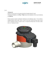
4. Transport und LagerungDas Membranventil muss sorgfältig behandelt, transportiert und gelagert werden:• Membranventil in seiner Originalverpackung transportieren und lagern• Vor schädlichen Einflüssen wie Staub, Schmutz, Feuchtigkeit sowie Wärme- und UV-Strahlung schützen• Anschlussenden dürfen weder durch mechanische noch durch sonstige Einflüsse beschädigtwerden• Ventil in gleicher Stellung wie geliefert lagern5. Funktionsweisen5.1 ÜbersichtLegende1 = Optische Stellungsanzeige mit Anzeigekappe2 = Hubkolben3 = Luftanschlüsse4 = Vollkunststoffgehäuse5 = Membranhalter6 = Druckstück7 = Membrane8 = Ventilkörper9 = Vorgespannte Federpakete für Funktion FC10 = Feder für Funktion FOOhne Feder Funktion DAWerkstoff der Membrane anhand der Farbe desRasterelements am Ventilkörper erkennbar:EPDMschwarzPTFE/EPDM weissPTFE/FPM grünFPMrotNBRblau5
5.2 Funktion FC / Federkraft schliessendIm Ruhezustand ist das Ventil durch Federkraft geschlossen. Wird der Stellantrieb mitdem Steuermedium beaufschlagt (Anschluss unten), öffnet das Ventil. Entweicht dasSteuermedium, wird das Ventil durch die Federkraft geschlossen.Druckstufen und BaureihenAnmerkungen• Bitte beachten Sie die zugehörigen Druck-Temperatur-Diagramme in den Planungsgrundlagen• Die angegebenen Druckstufen sind abhängig vom Material des VentilkörperBaureiheUnterteilWerkstoffMembrane20DN15...50DN40Six FC Ten FC Sixteen FCPVC-U, PVC-C, ABS, PP-H,PVC-U, PVC-C, ABS, PP-HPP-n, PVDF, PVDF-HPEPDM PTFE Steuerdruckmax.EPDM PTFESteuerdruckmax.PVC-U, PVDF,PVC-C, ABS, PP-H, PP-nPVDF-HPEPDM PTFESteuerdruck EPDM PTFE Steuerdruckmax.max.6 bar --- 6 bar 10 bar 10 bar 6 bar 10 bar 10 bar 6 bar 16 bar 16 bar 6 bar63DN50 6 bar --- 6 bar 10 bar 6 bar 6 bar 10 bar 10 bar 6 bar 16 bar 10 bar 6 barBetriebsdruck → ---- → → →← →← → →LuftanschlussAuswahl Magnetventil und zugehörige AnschlussgewindeZur Ansteuerung des einfach wirkenden Antriebs FC werden 3/2-Wege-Magnetventileverwendet. Der Anschluss erfolgt je nach Bedarf über eine Hohlschraube direkt amStellantrieb oder abgesetzt über Mehrfach-Anschlussplatten bzw. Ventilinseln.Funktion FC mit einem Magnetventil 3/2-Wege beim Anschluss untenNennweite Six (FC) Ten (FC) Sixteen (FC)20DN15G1/8"25DN20G1/8"32DN25G1/8"40DN32 G1/8" G1/4"50DN40 G1/8" G1/4"63DN50 G1/8" G1/4"6
Zusammenhang zwischen Leitungsdruck und FederpaketenDie Schliesskräfte der Antriebe wurden auf die spezifizierte Druckstufe PN ausgelegt.Der Betrieb bei sehr geringen Leitungsdrücken führt zu erhöhtem Membranverschleiss.Um die Lebensdauer bei geringen Leitungsdrücken zu verlängern, kann die Anzahl derFederpakete reduziert werden.Für die spezifische Auslegung kontaktieren Sie bitte Ihren +GF+ Ansprechpartner.WarnungReduktion der FederpaketeReduzierung der Federpakete führt zur Reduktion der Schliesskraft. Durch einAnsteigen des Leitungsdrucks kann das Membranventil bei fehlenden Federpaketennicht mehr oder nicht mehr vollständig das Leitungssystem absperren.Tododer schwere Verletzungen durch offenes Leitungssystem. Die Funktiondes Prozesses kann beeinträchtigt werden.• Auslegung der <strong>Membranventile</strong> und Federpakete je nach LeitungsdruckSteuermediumAnmerkungen• 6 bar maximal für die Funktion FC; niedrige Steuerdrücke durch Reduktion der Federpaketemöglich• Druckluftklasse (ISO 8573-1) 2 oder 3 bei –10 °C und 3 oder 4 bei T ›0°C• Temperatur des Steuermediums max. 40°C• Ab einem Leitungsdruck von 10 bar muss die Abluft des Steuermediums gedrosseltwerden (Stellzeit Antrieb auf ca. 3 s einstellen)• Zugehörige Steuerdruckdiagramme und weitere Informationen finden Sie im Kapitel„6.6 Steuerdruckdiagramme“ und in den Georg Fischer PlanungsgrundlagenSteuervolumenNennweiteSix (FC)[dm³]Ten (FC)[dm³]20DN15 0.07 0.07 0.2025DN20 0.20 0.20 0.2032DN25 0.22 0.22 0.4040DN32 0.40 0.40 0.7850DN40 0.44 0.77 0.8563DN50 0.44 1.20 1.33Sixteen (FC)[dm³]7
5.3 Funktion FO / Federkraft öffnendIm Ruhezustand ist das Ventil durch Federkraft geöffnet. Wird der Stellantrieb mit demSteuermedium beaufschlagt (Anschluss oben), schliesst das Ventil. Entweicht das Steuermedium,wird das Ventil durch die Federkraft geöffnet.Druckstufen und BaureihenAnmerkungen• Bitte beachten Sie die zugehörigen Druck-Temperatur-Diagramme in den Planungsgrundlagen• Die angegebenen Druckstufen sind abhängig vom Material des VentilkörpersBaureiheTen FO/DASixteen FO/DAPVC-U, PVC-C, ABS, PP-H, PP-n,Unterteil WerkstoffPVC-C, ABS, PP-H, PP-nPVDF, PVDF-HPSteuerdruckSteuerdruckMembrane EPDM PTFEEPDM PTFEmax.max.PVC-U, PVDF, PVDF-HPEPDM20DN15...50DN40 10 bar 10 bar 5 bar 10 bar 10 bar 5 bar 16 bar 16 bar 5 barPTFESteuerdruckmax.63DN50 10 bar 10 bar 5 bar 10 bar 10 bar 5 bar 16 bar 16 bar 5 / 6 barBetriebsdruck →← →← →← →← → →LuftanschlussAuswahl Magnetventil und zugehörige AnschlussgewindeZur Ansteuerung des einfach wirkenden Antriebs FO werden 3/2-Wege-Magnetventileverwendet. Der Anschluss erfolgt je nach Bedarf über eine Hohlschraube direkt amStell antrieb oder abgesetzt über Mehrfach-Anschlussplatten bzw. Ventilinseln.Funktion FO mit einem Magnetventil 3/2-Wege beim Anschluss obenNennweite20DN1525DN2032DN2540DN3250DN4063DN50Ten / Sixteen (FO)G1/8“G1/8“G1/8“G1/8“G1/4“G1/4“8
SteuermediumAnmerkungen• 5 bar maximal für die Funktion FO. Bei der Dimension DN50 und ab einem Leitungsdruckvon 10 bar beträgt der max. Steuerdruck 6 bar• Ab einem Leitungsdruck von 10 bar muss die Abluft des Steuermediums gedrosseltwerden (Stellzeit Antrieb auf ca. 3 s einstellen)• Druckluftklasse (ISO 8573-1) 2 oder 3 bei –10 °C und 3 oder 4 bei T ›0°C• Temperatur des Steuermediums max. 40°C• Abhängig vom Betriebsdruck PN können niedrige Steuerdrücke gewählt werden• Zugehörige Steuerdruckdiagramme und weitere Informationen finden Sie im Kapitel„6.6 Steuerdruckdiagramme“ oder in den Georg Fischer PlanungsgrundlagenSteuervolumenNennweite20DN15 0.0725DN20 0.2032DN25 0.2340DN32 0.4450DN40 0.8663DN50 1.52Ten / Sixteen (FO)[dm³]5.4 Funktion DA / Doppelt wirkendDas Ventil hat keine definierte Grundposition. Öffnen und Schliessen des Ventils wirddurch Anlegen des Steuerdrucks an den entsprechenden Anschluss realisiert (Anschlussoben für Schliessen, Anschluss unten für Öffnen).Druckstufen und BaureihenAnmerkungen• Bitte beachten Sie die zugehörigen Druck-Temperatur-Diagramme in den Planungsgrundlagen• Die angegebenen Druckstufen sind abhängig vom Material des VentilkörpersBaureiheTen FO/DASixteen FO/DAPVC-U, PVC-C, ABS, PP-H, PP-n,Unterteil WerkstoffPVC-C, ABS, PP-H, PP-nPVDF, PVDF-HPSteuerdruckSteuerdruckMembrane EPDM PTFEEPDM PTFEmax.max.PVC-U, PVDF, PVDF-HPEPDM20DN15...50DN40 10 bar 10 bar 5 bar 10 bar 10 bar 5 bar 16 bar 16 bar 5 barPTFESteuerdruckmax.63DN50 10 bar 10 bar 5 bar 10 bar 10 bar 5 bar 16 bar 16 bar 5 / 6 barBetriebsdruck →← →← →← →← → →9
LuftanschlussAuswahl Magnetventil und zugehörige AnschlussgewindeZur Ansteuerung von doppelt wirkenden Antrieben DA werden 4/2- oder 5/2-Wege-Magnetventileverwendet. Der Anschluss kann je nach Bedarf über eine Namur-Anschlussplattedirekt am Stellantrieb oder abgesetzt über Ventilinseln erfolgen.Funktion DA mit einem Magnetventil 4/2- bzw. 5/2-Wege. Beide Anschlüsse werden verwendetNennweite20DN1525DN2032DN2540DN3250DN4063DN50Ten / Sixteen (DA)G1/8“G1/8“G1/8“G1/8“G1/4“G1/4“SteuermediumAnmerkungen• 5 bar maximal für die Funktion DA. Bei der Dimension DN50 und ab einem Leitungsdruckvon 10 bar beträgt der max. Steuerdruck 6 bar• Ab einem Leitungsdruck von 10 bar muss die Abluft des Steuermediums gedrosseltwerden (Stellzeit Antrieb auf ca. 3 s einstellen)• Druckluftklasse (ISO 8573-1) 2 oder 3 bei –10 °C und 3 oder 4 bei T ›0°C• Temperatur des Steuermediums max. 40°C• Abhängig vom Betriebsdruck PN können niedrige Steuerdrücke gewählt werden• Zugehörige Steuerdruckdiagramme und weitere Informationen finden Sie im Kapitel„6.6 Steuerdruckdiagramme” oder in den Georg Fischer PlanungsgrundlagenNennweiteTen / Sixteen (DA)[dm³]Geschlossen Offen20DN15 0.07 0.0725DN20 0.20 0.2032DN25 0.23 0.2240DN32 0.44 0.4050DN40 0.86 0.7763DN50 1.52 1.2010
6. Einbau in Rohrleitung6.1 Allgemeine InformationFür den Einbau von <strong>Membranventile</strong>n mit pneumatischem Antrieb gelten die gleichenAnweisungen wie für die Verbindung von Rohren, Fittings und ähnlichen Rohrleitungselementen.Detaillierte Informationen können den entsprechenden Kapiteln der „GeorgFischer Planungsgrundlagen“ entnommen werden.6.2 Vorgehensweise EinbauWarnungVerwendung von Schmiermitteln an Gewindeverbindung zwischen Gehäusemutterund VentilkörperVerwendung von Schmiermitteln kann, speziell bei amorphen Kunststoffen,Spannungsrisse im Ventilkörper verursachen. Folgen können Tod oder schwereVerletzungen durch Kontakt mit Medium sein. Funktionsfähigkeit des Ventilsist nicht mehr gewährleistet.• Unabhängig vom Ventilkörper-Werkstoff keine Schmiermittel an Gewindeverbindungzwischen Gehäusemutter und Ventilkörper verwendenBitte prüfen Sie das Membranventil vor dem Einbau gemäss den folgenden Punkten:• Untersuchung des Ventils auf Transportschäden, keine beschädigten Ventile einbauen• Sicherstellen, dass Membranventil mit Druckklasse, Anschlussart, Anschlussabmessungund Werkstoff den Einsatzbedingungen entspricht• Funktionsprobe durchführen, indem das Membranventil geschlossen und geöffnet wird• Membrane und andere Dichtelemente vor dem Einbau auf Alterungsschäden kontrollieren.Teile mit Verhärtungen und Rissen nicht einbauen• Kein Ventil mit Funktionsstörung einbauen• Durchführung einer wiederholten Funktionsprüfung11
6.3 Anmerkungen zu VerbindungstechnikenJeder Ventilkörpertyp beschreibt eine Anschlussvariante:Type 514 Type 515Radial ein- und ausbaubarStutzenvarianteType 517 Type 519FlanschvarianteAbgangsventilHINWEISBefestigung des MembranventilsDurch Temperaturwechsel verursachte Wärmeausdehnungen führen zuLängs- bzw. Biegekräften, die das Ventil beschädigen können.• Kräfte durch Festpunkte vor bzw. hinter dem Ventil aufnehmenIn angeschlossener Leitung ruft Betätigung des Membranventils Reaktionskräftehervor, die das Ventil beschädigen können.• Membranventil befestigen oder die zugehörige Rohrleitung direkt vor undnach dem Ventil mit zugehörigen Halterungen befestigenÜberlagerung von Beanspruchungen können das Membranventil beschädigen.• Membranventil und Rohrleitung müssen fluchtenRadial ein- und ausbaubares VentilAlle Materialien mit Ventilkörper Typ 5141. Überwurfmuttern lösen und auf vorgesehene Rohrenden schieben2. Anschlussteile je nach Art auf Rohrenden kleben, schrauben oder schweissen (daskonkrete Vorhaben ist in den Planungsgrundlagen beschrieben)3. Membranventil zwischen Anschlussteile setzen4. Überwurfmuttern von Hand festziehen12
KlebeverbindungPVC-U, PVC-C und ABS - Typen 514, 515Nur identische Werkstoffe miteinander verbinden. Nach Aushärtungszeit der Verbindung,Rohrleitungsabschnitt so schnell wie möglich drucklos mit Wasser spülen (siehe Kapitel„Verbindungstechniken” in den „Georg Fischer Planungsgrundlagen”)SchweissverbindungPP-H, PP-n, PVDF, PVDF-HP - Typen 514, 515, 519Nur identische Werkstoffe miteinander verbinden (siehe Kapitel „Verbindungstechniken”in den „Georg Fischer Planungsgrundlagen”).FlanschverbindungAlle Materialien mit Ventilkörper Typ 517Anzugsdrehmomente der Schrauben den entsprechenden Kapiteln der „Georg FischerPlanungsgrundlagen” entnehmen.6.4 Flexibler LuftanschlussDurch die runde Geometrie des Membranventils können die Luftanschlüsse des Antriebsin 90°-Schritten beliebig positioniert werden.WarnungAusbau des Membranventils oder Öffnen der GehäusemutterUnkontrolliertes Austreten oder Nachfliessen des Mediums aus Leitung oderVentil, unter Druck oder drucklos. Rückstände von gesundheitsschädlichen,aggressiven, brennbaren oder explosiven Medien in Leitung oder Ventil. Tododer schwere Verletzungen durch Kontakt mit Medium.• Druck in Rohrleitung muss vollständig abgebaut sein• Rohrleitung muss vollständig entleert sein• Spülen des Systems bei Verwendung von aggressiven, schädlichen, brennbarenund explosiven Medien• Ventil muss vollständig entleert sein, dazu Ventil vollständig leer laufen lassenVorgehensweise – Positionierung des Luftanschlusses1. Leitung entleeren und drucklos machen, Warnhinweis „Ausbau des Membranventilsoder Öffnen der Gehäusemutter” beachten2. Ventile mit Funktion FC und DA mit Steuermedium in Stellung „auf“ bringen13
3. Gehäusemutter mit Hilfe eines Bandschlüssels aufschraubenAnmerkung - Entrasten des Rasterelements ist deutlich hörbar4. Ventil mit Steuermedium in Stellung „zu“ bringen, um Membrane im Folgenden neuauszurichten5. Antrieb beliebig um 90° drehen6. Membrane zum Dichtsteg neu ausrichten. Anschliessend Membrane handfest im Uhrzeigersinnanziehen und gegen den Uhrzeigersinn lösen bis Membranposition erreichtist (min. 90°)Bei Montage: Ohren der Membrane genau zwischen die schmalen Führungsstege desInnengehäuses positionieren7. Ventil mit Funktion FC und DA wieder in Stellung „auf“ bringen8. Antrieb auf Ventilkörper setzen und Gehäusemutter handfest anziehen9. Ventil mit Steuermedium in Stellung „zu” bringen14
7. Ventil mit Funktion FC und DA wieder in Stellung „auf“ bringen - die Membrane ist nunzentriert8. Gehäusemutter mit Hilfe des Bandschlüssels festdrehen, bis ...... ein Spaltmass von 0,5 bis 1 mm zwischen Ventilkörper und Gehäusemutter erreichtist... der halbrunde Indikator an Gehäusemutter mit Rasterelement am Ventilkörperfluchtet.TippBei Ventilen mit eingebauter Hubbegrenzung empfehlen wir das Ventil neueinzustellen.6.5 Ansteuerung des AntriebsMagnetventile je nach Funktionsweise (FO, FC oder DA), gemäss Empfehlungen aus Kapitel„Funktionsweisen” anschliessen.6.6 SteuerdruckdiagrammeDie nachfolgenden Diagramme zeigen den Steuerdruck in Abhängigkeit vom NenndruckPN.DIASTAR Six, FC mit EPDM Membrane6.5DN504DN20 - 40P [bar]3DN152100 1 2 3 4 5 6 7 8 9 10PN [bar]15
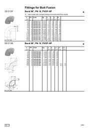
DIASTAR TEN, FC mit EPDM Membrane6DN15 - 5054P [bar]32100 1 2 3 4 5 6 7 8 9 10PN [bar]DIASTAR TEN, FC mit PTFE Membrane6DN15 - 5054P [bar]32100 1 2 3 4 5 6 7 8 9 10PN [bar]DIASTAR TEN, FO und DA mit EPDM Membrane654DN15 - 32P [bar]3DN40 - 502100 1 2 3 4 5 6 7 8 9 10PN [bar]DIASTAR TEN, FO und DA mit PTFE Membrane654DN50P [bar]3DN15/25/32/402DN20100 1 2 3 4 5 6 7 8 9 10PN [bar]16
DIASTAR SIXTEEN, FC mit EPDM Membrane6DN15 - 5054P [bar]32100 1 2 3 4 5 6 7 8 9 10PN [bar]DIASTAR SIXTEEN, FC mit PTFE Membrane6DN15 - 5054P [bar]32100 1 2 3 4 5 6 7 8 9 10 11 12 13 14 15 16PN [bar]DIASTAR SIXTEEN, FO und DA mit EPDM Membrane654DN50P [bar]3DN15/25/322DN20/40100 1 2 3 4 5 6 7 8 9 10 11 12 13 14 15 16PN [bar]DIASTAR SIXTEEN, FO und DA mit PTFE Membrane6DN505DN25/32/404P [bar]3DN15/202100 1 2 3 4 5 6 7 8 9 10 11 12 13 14 15 16PN [bar]17
7. InbetriebnahmeBitte beachten Sie vor dem Einbau des Membranventils alle technischen Informationenund Warnhinweise! Für die Druckprobe von <strong>Membranventile</strong>n gelten dieselben Anweisungenwie für die Rohrleitungen, jedoch darf der Prüfdruck den PN des Membranventilsnicht überschreiten.HINWEIS Betätigung des MembranventilsAnwendung von erhöhten Steuerdrücken sowie mechanischen Hilfsmitteln,können zu einer Beschädigung des Membranventils führen.• Für die Betätigung nur die angegebenen Steuerdrücke anwendenHINWEISRegelbetriebDurch Kavitation können Schäden am Membranventil entstehen.• Ventil im optimalen Regelbetrieb einsetzenAnmerkungIm Regelbetrieb tritt bei der Regelkennlinie durch den Wechsel der Betätigungsrichtungeine geringfügige Hysterese auf.Vorgehensweise Inbetriebnahme• Kontrollieren, ob alle Armaturen in der erforderlichen Offen- oder Geschlossenstellungsind• Leitungssystem füllen und vollständig entlüften• Komponente mit niedrigsten PN bestimmt den maximal zulässigen Prüfdruck imLeitungsabschnitt• Während Druckprobe Armaturen und Anschlüsse auf Dichtheit prüfen8. Normalbetrieb und WartungDie Verbindung zwischen Ober- und Unterteil ist in regelmässigen Abständen auf Dichtheitzu prüfen. Bei Leckage oder sonstigen Störungen unbedingt „Allgemeine Sicherheitshinweise“und weitere Kapitel der „Georg Fischer Planungsgrundlagen” beachten.Regelmässige Prüfung der FunktionsfähigkeitEs wird empfohlen, dauernd geöffnete oder geschlossene <strong>Membranventile</strong> 1-2x pro Jahrzu betätigen, um ihre Funktionsfähigkeit zu überprüfen.Allgemeine Warnhinweise zu Normalbetrieb und WartungWarnungMembranventil als EndarmaturUmherspritzendes Medium beim Öffnen einer unter Druck stehenden Leitung.Folgen können Tod oder schwere Verletzungen durch Kontakt mit Medium sein.• Das Membranventil als Endarmatur nur öffnen, wenn Medium sicher aufgefangen,abgeleitet und Umherspritzen verhindert wird18
WarnungAusbau des Membranventils oder Öffnen der GehäusemutterUnkontrolliertes Austreten oder Nachfliessen des Mediums aus Leitung oderVentil, unter Druck oder drucklos. Rückstände von gesundheitsschädlichen,aggressiven, brennbaren oder explosiven Medien in Leitung oder Ventil. Folgenkönnen Tod oder schwere Verletzungen durch Kontakt mit Medium sein.• Druck in Rohrleitung muss vollständig abgebaut sein• Rohrleitung muss vollständig entleert sein• Spülen des Systems bei Verwendung von aggressiven, schädlichen, brennbarenund explosiven Medien• Ventil muss vollständig entleert sein, dazu Ventil vollständig leer laufenlassen8.1 WartungsintervalleWir empfehlen die regelmässige Inspektion der Membrane und des Ventilkörpers,spätes tens nach:• 100.000 Betätigungen bei weniger als 10 bar Nenndruck bei 20°C und Wasser• 50.000 Betätigungen bei mehr als 10 bar Nenndruck bei 20°C und WasserSollte das Durchflussmedium erhöhte Temperaturen, andere Chemikalien oder Partikelmit Abriebwirkung aufweisen, empfehlen wir eine häufigere Kontrolle. Die Membranekann kontrolliert werden, indem die Gehäusemutter fachgerecht demontiert wird.8.2 Wechseln der MembraneWarnungAusbau des Membranventils oder Öffnen der GehäusemutterUnkontrolliertes Austreten oder Nachfliessen des Mediums aus Leitung oderVentil, unter Druck oder drucklos. Rückstände von gesundheitsschädlichen,aggressiven, brennbaren oder explosiven Medien in Leitung oder Ventil. Folgenkönnen Tod oder schwere Verletzungen durch Kontakt mit Medium sein.• Druck in Rohrleitung muss vollständig abgebaut sein• Rohrleitung muss vollständig entleert sein• Spülen des Systems bei Verwendung von aggressiven, schädlichen, brennbarenund explosiven Medien• Ventil muss vollständig entleert sein, dazu Ventil vollständig leer laufenlassen1. Leitung entleeren und drucklos machen, Warnhinweis „Ausbau des Membranventilsoder Öffnen der Gehäusemutter” beachten2. Ventile mit Funktion FC und DA mit Steuermedium in Stellung „auf“ bringen19
3. Gehäusemutter mit Hilfe eines Bandschlüssels aufschrauben, Antrieb entnehmenAnmerkung - Entrasten des Rasterelements ist deutlich hörbar4. Zur Demontage: Antrieb in Stellung „zu“ bringen5. Antrieb festhalten und Membrane durch Drehen gegen den Uhrzeigersinn aus demGehäuse ausbauen6. Neue Membrane durch eindrehen im Uhrzeigersinn handfest einbauen und anschliessendwieder um min. 90° lösenBei Montage: um neue Membrane einzuschrauben, Antrieb für die ersten Umdrehungengerade aufstellen (Anzeigestift oben).Ohren der Membrane genau zwischen die schmalen Führungsstege des Innengehäusespositionieren7. Anschliessend Rasterelement am Ventilkörper mit Hilfe eines Schraubendrehers lösenund ersetzen. Neues Rasterelement eindrücken.20
8. Antrieb wieder in Stellung „auf” bringen9. Antrieb auf Ventilkörper setzen und Gehäusemutter handfest anziehen10. Ventil mit Steuermedium (FO, DA) in Stellung „zu” bringen11. Ventil wieder in Stellung „auf” bringen – die Membrane ist nun zentriert12. Gehäusemutter mit Hilfe des Bandschlüssels festdrehen, bis ...... ein Spaltmass von 0,5 bis 1 mm zwischen Ventilkörper und Gehäusemutter erreichtist und... der halbrunde Indikator an Gehäusemutter mit Rasterelement am Ventilkörperfluchtet.TippBei Ventilen mit eingebauter Hubbegrenzung empfehlen wir, das Ventil nach demWechsel neu einzustellen8.3 Wechseln der DichtungenWeitere Informationen erhalten Sie in den „Georg Fischer Planungsgrundlagen” imInternet unter www.piping.georgfischer.com oder über Ihre Georg Fischer Vertretungen.21
9. Hilfe bei StörungenBitte beachten Sie bei der Behebung von Störungen stets die Sicherheits- undWarn hinweise.Bei weiteren Störungen oder Fragen wenden Sie sich bitte an Ihre Georg FischerVer tretung!Art der StörungMassnahmenRohrleitungskräfte, besonders solche aus behinderter Wärmeausdehnung,können die Störungsursache sein. Die AbstützungRohrleitung und/oder Ventil verformen sichbzw. dehnen sich ausder Rohrleitung sollte verbessert werden.Wird nach dem Ausbau festgestellt, dass die Werkstoffe desGehäuses oder der Dichtung nicht genügend beständig sind.Vorzeitiger Verschleiss des MembranventilsGeeignete Werkstoffe aus der Liste „Chemische Widerstandsfähigkeiten“in den Planungsgrundlagen auswählen oder Ihre +GF+oder einzelner TeileVertretung kontaktieren.Leckage nach aussen an Flanschverbindung Verbindung nachziehen und ggf. Dichtung ersetzenLeckage nach aussen an Überwurfmutter Verbindung handfest nachziehen oder ggf. O-Ringe wechselnGehäusemutter nachziehen bis ...... ein Spaltmass von 0,5 bis 1 mm zwischen Ventilkörper undMediumsleckage an Verbindung zwischen Gehäusemutter erreicht istVentilkörper und Gehäusemutter... der halbrunde Indikator an Gehäusemutter mit Rasterelementam Ventilkörper fluchtet oder ggf. Membrane gemäss Kapitel„Wechseln der Membrane“ ersetzen.Membrane gemäss Kapitel „Vorgehensweise – Wechseln derLeckage im Sitz / DurchgangsleckageArmatur schwergängigLeckage des Steuermediums aus nicht angeschlossenemLuftanschlussArmatur übt nicht den spezifizierten Hubaus bzw. schliesst oder öffnet nichtMediumsleckage am AnzeigestiftLeckage des Steuermediums an EntlüftungMembrane verschleisst vorzeitigAntrieb schaltet nicht mehr – VereisungsspurenMembrane“ ersetzen .• Spindel auf Verschleiss kontrollieren und ggf. schmieren• ggf. Dichtungen und ggf. Funktionsteile ersetzenSpindel- und Kolbendichtung wechseln• Steuerdruck überprüfen• Funktion (FC, FO, DA) und zugehörige Anschlüsse überprüfen• Be- und Entlüftungsleitung auf Funktion prüfenSpindel- und Kolbendichtung sowie Membrane wechselnSpindel- und Kolbendichtung wechseln• Steuerdruck überprüfen• Funktion (FC, FO, DA) und zugehörige Anschlüsse überprüfen• Antriebsgrösse überprüfen• ggf. Anzahl der Federpakete bei Funktion FC reduzieren• Entlüftungsbohrung an Zwischenelement kontrollieren undggf. säubern• Chemische und mechanische Beständigkeit der MembraneüberprüfenKondensat ist eingefroren• Steuerluft trocknen• Anzeigekappe mit Moosgummidichtung abdichten22
10. ZubehörGenauere Informationen finden Sie im Kapitel „Zubehör für pneumatische Antriebe” inden „Georg Fischer Planungsgrundlagen“. Verfügbar sind:• Hubbegrenzung/Handnotbetätigung• Vorsteuer-Magnetventil• Rückmeldung mit Schalterbauarten• Silber-Nickel (AgNi)• Goldkontakt (Au)• Induktivschalter NPN und PNP• Induktivschalter NAMUR• Stellungsregler• Buskommunikation / AS-Interface11. Original EG-Konformitätserklärung für MaschinenHersteller:Georg Fischer Piping Systems Ltd., Ebnatstrasse 111, 8201 Schaffhausen / SwitzerlandPerson die bevollmächtigt ist technische Unterlagen zusammenzustellen:Georg Fischer Piping Systems Ltd., R&D Manager,Ebnatstrasse 111, 8201 Schaffhausen / SwitzerlandHiermit erklären wir, dass<strong>Pneumatische</strong> <strong>Membranventile</strong>Typ: DIASTAR Sixteen, DIASTAR Ten, DIASTAR SixVarianten: Federkraft öffnend, Federkraft schliessend, DoppeltwirkendArtikelnummern: 161614001-161657977, 163614012-163657877, 169614012-169657137,167614002-167659756, 168615112-168659356, 175624032-175679356,180624132-180679556konform ist mit den einschlägigen Bestimmungen der Maschinenrichtlinie (2006/42/EC).konform ist mit den einschlägigen Bestimmungen folgender weiterer EU-Richtlinien:• Druckgeräterichtlinie (97/23/EC), Kategorie 1, Modul A• Bauprodukterichtlinie (89/106/EC)Des Weiteren erklären wir, dass die folgenden sonstigen technischen Normen (oderTeile/Klauseln hiervon) und Spezifikationen angewandt worden sind• NA19 (Luftanschlüsse)Name: Manfred LeyrerPosition: Head of Quality and SustainabilityGeorg Fischer Piping SystemsDatum: 2010-01-0223
<strong>Pneumatic</strong><strong>Diaphragm</strong> ValveOriginal - Instruction ManualDIASTAR
Before installing or commissioning diaphragm valves please read this manualcarefully. This manual gives valuable recommendations to avoid personal injuriesand material damages.26
Content1. Intended use2. Requirements for user and operator responsiblity3. Safety messages4. Transport and storage5. Modes of operation5.1 General overview5.2 FC-mode5.3 FO-mode5.4 DA-mode6. Installation6.1 General information6.2 Installation process6.3 Information regarding jointing techniques6.4 Flexible air connection6.5 Controlling the actuator6.6 Control pressure diagrams7. Commissioning8. Normal operation and maintenance8.1 Maintenance interval8.2 Replacing diaphragm8.3 Replacing the seals9. Help in case of problems10. Accessories11. Original EC-Declaration of Conformity for machinery27
Related documents to this instruction manualThe „Georg Fischer Planning Fundamentals“give you additional information for the use ofdiaphragm valves. The Planning Fundamentals may be obtained from your Georg Fischersales company or via www.piping.georgfischer.com1. Intended useThe diaphragm valves with DIASTAR actuator are intended exclusively for shutting off andconveying media in the allowable pressure and temperature range or for controlling flowin piping systems into which they have been installed.2. Requirements for user and operator responsibility• The diaphragm valve must only be used according to the specifications for which it hasbeen intended, as indicated in the previous paragraph• Piping system must be installed by professionals, its functionality is checked regularly• Installation, operation, service and repairs must be carried out by qualified personnel• Users and operators must be instructed on a regular basis in all aspects of work safetyand environmental protection especially those pertaining to pressure–bearing pipingsystem• The users and operators must be familiar with the operating instructions and mustadhere to the information contained therein3. Safety messagesThe instruction manual is part of the machine and an important module of the safetyconcept.Observe instruction manualThe instruction manual is part of the product and an importaint module of the safetyconcept. Non-observance could result in serious injury or death.• Read and observe instruction manual• Instruction manual must be available at the machine• Pass instruction manual to following users of the machine4. Transport and storagePlease handle, transport and store the diaphragm valve carefully:• The diaphragm valve should be transported and stored in its original packaging• The valve must be protected from harmful influences such as dirt, dust, humidity, andespecially heat and UV radiation• The connection ends should not be damaged mechanically or in any other way• The diaphragm valve should be stored in the same position as delivered28
5. Modes of operation5.1 General OverviewLegend1 = Optical position indicator with cap2 = Piston3 = Air connections4 = All-plastic housing5 = <strong>Diaphragm</strong> holder6 = Compressor7 = <strong>Diaphragm</strong>8 = Valve body9 = Pre-loaded spring sets for FC-mode10 = Spring for FO-modeDA-mode without spingsYou will recognize the type of diaphragm with thecolour of the friction lock on the valve body:EPDMblackPTFE/EPDM whitePTFE/FPM greenFPMredNBRblue29
5.2 FC-mode / Faile-safe-to-closeIn the non-operative state, the valve is closed with spring force. When the actuator ispressurised with the control medium (bottom connection), the valve opens. When thecontrol medium escapes, the valve is closed via spring force.Pressure ranges and typesInformation• Please consider the pressure-temperature diagrams in the Planning Fundamentals• Shown pressure ranges depend on the valve body materialTypeValve bodymaterial<strong>Diaphragm</strong>20DN15...50DN40Six FC Ten FC Sixteen FCPVC-U, PVC-C, ABS, PP-H,PVC-U, PVC-C, ABS, PP-HPP-n, PVDF, PVDF-HPEPDM PTFEControlpressuremax.EPDM PTFEControlpressuremax.PVC-C, ABS, PP-H, PP-nEPDM PTFEControlpressuremax.PVC-U, PVDF,PVDF-HPEPDMPTFEControlpressuremax.6 bar --- 6 bar 10 bar 10 bar 6 bar 10 bar 10 bar 6 bar 16 bar 16 bar 6 bar63DN50 6 bar --- 6 bar 10 bar 6 bar 6 bar 10 bar 10 bar 6 bar 16 bar 10 bar 6 barWorking pressure→ ---- → → →← →← → →Air connectionSolenoid pilot valve and matching connection thread3/2-way solenoid valves are used to control single acting actuators (FC). They are mountedeither directly to the actuator via a banjo bolt or via a battery mounting plate or valvecluster, as required.FC mode of operation with a 3/2-way solenoid valve for bottom connectionNominaldiameterSix (FC) Ten (FC) Sixteen (FC)20DN15G1/8"25DN20G1/8"32DN25G1/8"40DN32 G1/8" G1/4"50DN40 G1/8" G1/4"63DN50 G1/8" G1/4"30
Relation between line pressure and spring setsThe closing force of the actuators were designed for the specified PN rating. Operationwith low line pressure can cause increase diaphragm wear. In order to extend the diaphragmlife span with low line pressure, the number of spring packages can be reduced.Please contact your +GF+ partner for advice.WarningReducing spring setsReduced spring sets lead to a reduced closing force. At a rising line pressurethe valve can not close or not close properly due to missing spring sets. Deathor serious injury could occur due to open piping. The process can be influencednegatively.• Configure diaphragm valve and actuator according to your line pressureControl mediumInformation• 6 bar max. for the FC-mode; lower control pressure possible due to reduced spring sets• Compressed air class (ISO 8573-1) 2 or 3 for –10 °C and 3 or 4 for T ›0 °C• Temperature of control medium, max. 40 °C• When pressure exeeds 10 bar the controll pressure must be throttled by exhaust air(adjust actuating time to approx. 3 s)• Please consider control pressure diagrams in the chapter “6.6 Control pressure diagrams”or in the Georg Fischer Planning FundamentalsControl volumeNominal diameterSix (FC)[dm³]Ten (FC)[dm³]20DN15 0.07 0.07 0.2025DN20 0.20 0.20 0.2032DN25 0.22 0.22 0.4040DN32 0.40 0.40 0.7850DN40 0.44 0.77 0.8563DN50 0.44 1.20 1.33Sixteen (FC)[dm³]31
5.3 FO-mode / Fail-safe-to-openIn the non-operative state, the valve is open with spring force. When the actuator is pressurisedwith the control medium (top connection), the valve closes. When the controlmedium escapes, the valve is opened via spring force.Pressure ranges and typesInformation• Please consider the pressure-temperature diagrams in the Planning Fundamentals• Shown pressure ranges depend on the valve body materialTypeTen FO/DASixteen FO/DAPVC-U, PVC-C, ABS, PP-H, PP-n,Valve body materialPVC-C, ABS, PP-H, PP-nPVDF, PVDF-HPControl pressuremax.sureControl pres-<strong>Diaphragm</strong> EPDM PTFEEPDM PTFEmax.PVC-U, PVDF, PVDF-HPEPDM20DN15...50DN40 10 bar 10 bar 5 bar 10 bar 10 bar 5 bar 16 bar 16 bar 5 barPTFEControl pressuremax.63DN50 10 bar 10 bar 5 bar 10 bar 10 bar 5 bar 16 bar 16 bar 5 / 6 barWorking pressure →← →← →← →← → →Air connectionSolenoid pilot valve and matching connection thread3/2-way solenoid valves are used to control single acting actuators (FO). They are mountedeither directly to the actuator via a banjo bolt or via a battery mounting plate or valvecluster, as required.FO mode of operation with a 3/2-way solenoid valve for top connectionNominal diameter20DN1525DN2032DN2540DN3250DN4063DN50Ten / Sixteen (FO)G1/8“G1/8“G1/8“G1/8“G1/4“G1/4“32
Control mediumInformation• 5 bar max. for the FO-mode. For DN50 and from a line pressure of 10 bar the controlpressure is 6 bar max.• When pressure exeeds 10 bar the controll pressure must be throttled by exhaust air(adjust actuating time to approx. 3 s)• Compressed air class (ISO 8573-1) 2 or 3 for –10 °C and 3 or 4 for T ›0 °C• Temperature of control medium, max. 40 °C• Depending on the working pressure PN, lower control pressure may be selected• Please consider control pressure diagrams in the chapter “6.6 Control pressure diagrams“or in the Georg Fischer Planning Fundamentals.Control VolumeNominal diameter20DN15 0.0725DN20 0.2032DN25 0.2340DN32 0.4450DN40 0.8663DN50 1.52Ten / Sixteen (FO)[dm³]5.4 DA-mode / Double actingThe valve has no defined basic position. The valve is opened and closed by applying controlpressure to the corresponding connection (top connection for closing, bottom connectionfor opening).Pressure ranges and typesInformation• Please consider the pressure-temperature diagrams in the Planning Fundamentals• Shown pressure ranges depend on the valve body materialTypeTen FO/DASixteen FO/DAPVC-U, PVC-C, ABS, PP-H, PP-n,Valve body materialPVC-C, ABS, PP-H, PP-nPVDF, PVDF-HPControl pressuremax.sureControl pres-<strong>Diaphragm</strong> EPDM PTFEEPDM PTFEmax.PVC-U, PVDF, PVDF-HPEPDM20DN15...50DN40 10 bar 10 bar 5 bar 10 bar 10 bar 5 bar 16 bar 16 bar 5 barPTFEControl pressuremax.63DN50 10 bar 10 bar 5 bar 10 bar 10 bar 5 bar 16 bar 16 bar 5 / 6 barWorking pressure →← →← →← →← → →33
Air connectionSolenoid pilot valve and matching connection thread4/2-way or 5/2-way solenoid valves are used to control double acting actuators (DA). Theycan be mounted either directly to the actuator via a Namur connector plate or via valveclusters.The DA-mode of operation with a 4/2- or 5/2-way solenoid valve.Both connections are usedNominal diameter20DN1525DN2032DN2540DN3250DN4063DN50Ten / Sixteen (DA)G1/8“G1/8“G1/8“G1/8“G1/4“G1/4“Control mediumInformation• 5 bar max. for the DA-mode. For DN50 and from a line pressure of 10 bar the controlpressure is 6 bar max.• When pressure exeeds 10 bar the controll pressure must be throttled by exhaust air(adjust actuating time to approx. 3 s)• Compressed air class (ISO 8573-1) 2 or 3 for –10 °C and 3 or 4 for T ›0 °C• Temperature of control medium, max. 40 °C• Depending on the working pressure PN, lower control pressure may be selected• Please consider the control pressure diagrams in the chapter “6.6 Control pressurediagrams“ or in the Georg Fischer Planning FundamentalsNominal diameter Ten / Sixteen (DA)[dm³]CloseOpen20DN15 0.07 0.0725DN20 0.20 0.2032DN25 0.23 0.2240DN32 0.44 0.4050DN40 0.86 0.7763DN50 1.52 1.2034
6. Installation6.1 General information<strong>Diaphragm</strong> valve installation in a piping system is subject to the same regulations asother connecting elements of pipes, fittings and related piping system components. Furtherchapters in the Georg Fischer Planning Fundamentals give you additional informationregarding installation and jointing methods.6.2 Installation processWarningUse of grease on the threaded connection between housing nut and valvebodyThe use of grease, especially on amorphous plastics, can cause stress crackingon the valve body. Death or serious injury could occur due to contact withthe medium. The function of the valve is not warranted.• Irrespective of the valve body material, do not use grease for the threadedconnection between housing nut and valve bodyBefore installation, please check the diaphragm valve accordingly to the following points:• Inspect the diaphragm valve for transport damages. Damaged valves must not be installed• Only use diaphragm valves where the valve and the diaphragm correspond specificallyto the materials, pressure rating, type of connection and dimensions for the particularapplication• Carry out function test: open and close the diaphragm valve• <strong>Diaphragm</strong>s and other sealing elements should be checked before mounting to makesure there are no damages from aging. Aged parts which exhibit hardening or fissuresmust not be installed• You must not install valves which do not function properly• After installation another function test is to be carried out35
4.3 Information regarding jointing techniquesEach type of valve body describes a connection type:Type 514 Type 515True union designSpigot endsType 517 Type 519FlangesBranched typeNOTICEFixation of the diaphragm valveDue to temperature changes, longitudinal or lateral forces may occur if thermalexpansion is constrained.• Absorb forces via respective fixed points in front or after the valveOperation of a valve causes reactive forces which could damage the valve.• Mount the diaphragm valve or reinforce the piping directly before and afterthe diaphragm valve with suit able supportsSuperimposed loadings could damage the diaphragm valve• <strong>Diaphragm</strong> valve and piping must be alignedTrue Union DesignAll materials with valve body type 5141. Loosen the union nut and push them toward the designated piping end.2. Depending on the type of piping end, connecting parts are cemented, screwed orwelded. The Georg Fischer Planning Fundamentals include addi tional information.3. <strong>Diaphragm</strong> valve is then positioned between the connecting parts.4. Manually tightened the union nuts.36
Cement connectionsPVC-U, PVC-C and ABS - types 514, 515Only identical materials may be joined together.Pipesections with solvent cement connectionsshould be rinsed unpressurized with water after the drying time (see chapterjointing methods in the Georg Fischer Planning Fundamentals).Fusion connectionsPP-H, PP-n, PVDF, PVDF-HP - types 514, 515, 519Only identical materials may be joined together (see chapter jointing methods in the GeorgFischer Planning Fundamentals).Flange connectionsAll materials with valve body type 517The tightening torque can be found in further chapters in the Georg Fischer PlanningFundamentals.4.4 Flexible air connectionThe air connection is turnable in 90° intervals due to the round design.WarningDismounting diaphragm valve or opening the housing nutThe medium may exit uncontrollably or flow out from the pipe or valve, whetherunder pressure or not. The valve or pipe may contain residue or remnants ofan aggressive, hazardous, flammable or explosive medium. Death or seriousinjury could occur due to contact with the medium.• Release all pressure from the piping system• Empty the piping system completely• Rinse the system, if aggressive, hazardous, flammable or explosive mediaare involved• Empty the diaphragm valve completely when is has been dismounted. Inorder to do so, let the valve drain completelyProcedure – Positioning of air connection1. Drain and de-pressurized the pipeline. Please consider the safety message “Dismountingdiaphragm valve or opening the housing nut”.2. Move the valve into the “open” position with the control medium (FC,DA)37
3. Open housing nut with a strap wrenchInformationOn opening: unlatching of the friction lock is clearly audible4. Move the valve into the „closed“ position with the control medium to realign diaphragmin the next step5. Turn actuator in 90° intervals to the desired position6. Realign diaphragm and compression piece. After this tighten the diaphragm handtight(clockwise) and then turn the diaphragm back (counter clockwise) by min. 90 ° to theright positionFor assembly: <strong>Diaphragm</strong> tabs must be positioned between the narrow guiding barsof the inner housing7. Put valve in the „open“ position again with the control medium (FC, DA)8. Position actuator on the valve body and tighten housing nut handtight9. Move the valve into the „closed“ position with the control medium38
10. Put the valve in the „open“ position again with the control medium (FC,DA) –diaphragm is now centered11. Screw housing nut with strap wrench tight, till...... a uniform all-around gap of 0.5 up to 1 mm between valve body and bonnet is achievedand... the half-round position indicator is align with the friction lockTipFor valves with a built-in stroke limiter, we recommend to read just the valve.6.5 Controlling the actuatorDepending on the mode of operation (FO, FC or DA), please connect solenoid valve accordingto chapter “Modes of operation”.6.6 Control pressure diagramsThe following diagrams show the control pressure depending on the nominal pressurePN.DIASTAR SIX, FC with EPDM diaphragm6DN5054DN20 - 40P [bar]3DN152100 1 2 3 4 5 6 7 8 9 10PN [bar]39
DIASTAR TEN, FC with EPDM diaphragm6DN15 - 5054P [bar]32100 1 2 3 4 5 6 7 8 9 10PN [bar]DIASTAR TEN, FC with PTFE diaphragm6DN15 - 5054P [bar]32100 1 2 3 4 5 6 7 8 9 10PN [bar]DIASTAR TEN, FO and DA with EPDM diaphragm654DN15 - 32P [bar]3DN40 - 502100 1 2 3 4 5 6 7 8 9 10PN [bar]DIASTAR TEN, FO and DA with PTFE diaphragm654DN50P [bar]3DN15/25/32/402DN20100 1 2 3 4 5 6 7 8 9 10PN [bar]40
DIASTAR SIXTEEN, FC with EPDM diaphragm6DN15 - 5054P [bar]32100 1 2 3 4 5 6 7 8 9 10PN [bar]DIASTAR SIXTEEN, FC with PTFE diaphragm6DN15 - 5054P [bar]32100 1 2 3 4 5 6 7 8 9 10 11 12 13 14 15 16PN [bar]DIASTAR SIXTEEN, FO and DA with EPDM diaphragm654DN50P [bar]3DN15/25/322DN20/40100 1 2 3 4 5 6 7 8 9 10 11 12 13 14 15 16PN [bar]DIASTAR SIXTEEN, FO and DA with PTFE diaphragm6DN505DN25/32/404P [bar]3DN15/202100 1 2 3 4 5 6 7 8 9 10 11 12 13 14 15 16PN [bar]41
7. CommissioningPlease observe all aforementioned safety and technical information before you start commissioningthe diaphragm valve!<strong>Diaphragm</strong> valve pressure testing is subject to the same regulations as the pipingsystem; however, the test pressure may not exceed the PN of the diaphragm valve.NOTICEOperate the diaphragm valveUse of higher control pressures or mechnical aids can cause damage to thediaphragm valve.• Use mentioned control pressure to actuate the diaphragm valveNOTICEControl operationsDue to cavitation the diaphragm valve could be damaged.• Use valve only at optimal control operation conditions.InformationSlight hysteresis occurs in the steady state characteristics when the direction of actuationis changed.Procedure commissioning• Check that all valves are in the required open or closed position• Fill the piping system and deaerate completely• The component with the lowest PN determines the maximum allowable test pressurein the piping section• The valves and connections should be checked for a tight seal during the pressure test8. Normal operation and maintenanceThe connection between the bonnet and valve body should be checked for tightness atregular intervals. Please consider at leakage or other defects the chapter “General safetyinformation” and additional information in the Planning Fundamentals.Check functionality regularlyWe recommend checking the functionality of diaphragm valves which are kept permanentlyopened or closed. This can be done by unseating the diaphragm 1 to 2 times a year.Safety messages for normal operations and maintenanceWarning<strong>Diaphragm</strong> valve used as end valveMedium can exit uncontrollably, if piping system is opened under pressure.Death or serious injury could occur due to contact with the medium.• The end valve may only be opened when the medium can be caught or carriedoff safely and splashing is prevented by taking appropriate measures.42
WarningDismounting diaphragm valve or opening the housing nutThe medium may exit uncontrollably or flow out from the pipe or valve,whether under pressure or not. The valve or pipe may contain residue or remnantsof an aggressive, hazardous, flammable or explosive medium.Death or serious injury could occur due to contact with the medium.• Release all pressure from the piping system.• Empty the piping system completely.• Rinse the system, if aggressive, hazardous, flammable or explosive mediaare involved.• Empty the diaphragm valve completely when is has been dismounted. Inorder to do so, let the valve drain completely.8.1 Maintenance intervalWe recommend inspecting the diaphragm at the latest after:• 100,000 cycles with less than 10 bar nominal pressure at 20 °C and water• 50,000 cycles with 10 bar or higher nominal pressure at 20°C and waterIf the flow medium has higher temperatures, other chemicals or abrasive particles, werecommend more frequent inspections. The diaphragm can be checked by opening thehousing nut.8.2 Replacing diaphragmWarningDismounting diaphragm valve or opening the housing nutThe medium may exit uncontrollably or flow out from the pipe or valve,whether under pressure or not. The valve or pipe may contain residue or remnantsof an aggressive, hazardous, flammable or explosive medium.Death or serious injury could occur due to contact with the medium.• Release all pressure from the piping system.• Empty the piping system completely.• Rinse the system, if aggressive, hazardous, flammable or explosive mediaare involved.• Empty the diaphragm valve completely when is has been dismounted. Inorder to do so, let the valve drain completely.1. Drain and de-pressurized the pipeline. Please consider safety message “Dismountingdiaphragm valve or opening the housing nut”2. Move the valve into the “open” position with the control medium (FC,DA)43
3. Open housing nut with a strap wrench, take actuator outInformationOn opening: unlatching of the friction lock is clearly audible4. For dismounting: Move actuator in “closed” position5. Hold actuator tight and screw diaphragm counter clockwise out of the inner housing6. Screw new diaphragm clockwise into the inner housing and then turn the diaphragmback by min. 90°For assembly: To screw the new diaphragm in, the actuator must be positionedupright for the first turns.<strong>Diaphragm</strong> tabs must be positioned between the narrow guiding bars ofthe inner housing7. Replace friction lock on the valve body, therefore loose it with a screw driver. Push thenew one in44
8. Move the actuator in “open” position9. Position actuator on the valve body and tighten housing nut handtight8. Move the valve into the “closed” position with the control medium (FO, DA)9. Put the valve in the “open” position again with the control medium – diaphragm is nowcentered10. Screw housing nut with strap wrench tight, till...... a uniform all-around gap of 0.5 up to 1 mm between valve body and bonnet isachieved and... the half-round position indicator aligns with the friction lockTipFor valves with built-in stroke limiter, we recommend to read just the valve.6.2 Replacing SealsMore information can be found in the Georg Fischer Planning Fundamentals viawww.piping.georgfischer.com or contact your Georg Fischer representative.45
7. Help in case of problemsPlease observe the safety information when handling defects!In case of other malfunctions or further questions please contact your Georg Fischerrepresentative!Malfunction typeDeformation and expansion of piping / valvePremature wear of diaphragm valve or individualpartsLeakage to the outside at flange jointLeakage to the outside at union nutsLeakage between valve body and housingnut connectionLeakage at seatSluggish valveLeakage of control medium on the non connectedair connectionsValve does not perform specified stroke oreven does not close or openLeakage of medium at the indicator pinLeakage of medium at the indicator pinPremature wear of diaphragmActuator does not switch – marks of icingon the valveMeasures to be takenPiping stresses, especially those resulting from restricted thermalexpansion, can be the cause of the malfunction. Improve thepiping supportAfter dismounting, if you determine that the material of thehousing or the seal is inadequately resistant.Choose suitablematerials from the list of “Chemical Resistance” in the PlanningFundamentals or contact your +GF+ representationTighten joint or if necessary replace sealingsTighten joint with manual effort or if necessary change sealingsScrew housing nut tight, till...... a uniform all-around gap of 0.5 up to 1 mm between valve bodyand bonnet is achieved and... the half-round position indicator aligns with the friction lock orif necessary, replace diaphragm in accordance with the chapter“Replacing diaphragm”Replace diaphragm in accordance with the chapter “Procedure -Replacing diaphragm”• Check spindle for wear and if necessary grease the spindle• If necessary replace seals and other functional partsReplace sealings on the spindle and piston• Check control pressure• Check connections and suitable mode of function (FC, FO, DA)• Check function of aeration and deaeration lineReplace sealings on the spindle and piston. Replace diaphragmReplace sealings on the spindle and piston• Check control pressure• Check connections and suitable mode of function (FC, FO, DA)• Check size of actuator• If necessary reduce number of spings sets (FC mode)• Check and clean if necessary deaeration drill on the intermediatepiece• Check chemical and mechanical resistance of the used diaphragm.More information can be found in further chapters ofthe Planning FundamentalsCondensate is freezing• Dry control air• Seal indicator cap with a foamed rubber sealing46
8. AccessoriesMore detailed information can be found in the chapter “Accessories for pneumatic actuators”in the Georg Fischer Planning Fundamentals. Available are:• Stroke limiter/Emergency manual override• Solenoid pilot valve• Electrical Feedback available with the following limit switches:• Silver-nickel (AgNi)• Gold contacts (Au)• Inductive switch NPN and PNP• Inductive switch NAMUR• Positioner• Bus communication/AS-Interface9. Original EC-Declaration of Conformity for machineryManufacturer:Georg Fischer Piping Systems Ltd., Ebnatstrasse 111, 8201 Schaffhausen / SwitzerlandAuthorized person to compile the technical file:Georg Fischer Piping Systems Ltd., R&D ManagerEbnatstrasse 111, 8201 Schaffhausen / SwitzerlandHerewith we declare that<strong>Pneumatic</strong> diaphragm valves:Type: DIASTAR Sixteen, DIASTAR Ten, DIASTAR SixVariants: fail-safe to close, fail-safe to open, double acting stroke actuatorCode: 161614001-161657977, 163614012-163657877, 169614012-169657137, 167614002-167659756, 168615112-168659356, 175624032-175679356,180624132-180679556is in conformity with the relevant provision of the Machinery Directive (2006/42/EC)is in conformity with the provisions of the following other EC-Directives:• 97/23/EC on pressure equipment, category I, modul A• 89/106/EC on construction productsAnd furthermore, we declare that the following (parts/clauses of) other technical standardsand specifications have been used:• NA19 (air connections)Name: Manfred LeyrerPosition: Head of Quality and SustainabilityGeorg Fischer Piping SystemsDate: 2010-01-0247
GF Piping Systems > worldwide at homeOur sales companies and representativesensure local customer support in over 100 countries.www.piping.georgfischer.comArgentina / Southern South AmericaGeorg Fischer Central PlasticsSudamérica S.R.L.Buenos Aires, ArgentinaPhone +5411 4512 02 90gfcentral.ps.ar@georgfischer.comAustraliaGeorge Fischer Pty LtdRiverwood NSW 2210 AustraliaPhone +61(0)2 9502 8000australia.ps@georgfischer.comwww.georgefischer.com.auAustriaGeorg FischerRohrleitungssysteme GmbH3130 HerzogenburgPhone +43(0)2782 856 43-0austria.ps@georgfischer.comwww.georgfischer.atBelgium / LuxembourgGeorg Fischer NV/SA1070 Bruxelles/BrüsselPhone +32(0)2 556 40 20be.ps@georgfischer.comwww.georgfischer.beBrazilGeorg Fischer Ltda.04795-100 São PauloPhone +55(0)11 5525 1311br.ps@georgfischer.comwww.georgfischer.com.brCanadaGeorg Fischer Piping Systems LtdBrampton, ON L6T 4E3Phone +1(905)792 8005Fax +1(905)792 6667ca.ps@georgfischer.comwww.georgfischer.caChinaGeorg FischerPiping Systems Ltd ShanghaiPudong, Shanghai 201319Phone +86(0)21 58 13 33 33china.ps@georgfischer.comwww.georgfischer.cnDenmark / IcelandGeorg Fischer A/S2630 TaastrupPhone +45 (0)70 22 19 75info.dk.ps@georgfischer.comwww.georgfischer.dkFinlandGeorg Fischer AB01510 VANTAAPhone +358 (0)9 586 58 25Fax +358 (0)9 586 58 29www.georgfischer.fiinfo.fi.ps@georgfischer.comFranceGeorg Fischer SAS95932 Roissy Charles de Gaulle CedexPhone +33(0)1 41 84 68 84fr.ps@georgfischer.comwww.georgfischer.frGermanyGeorg Fischer GmbH73095 AlbershausenPhone +49(0)7161 302-0info.de.ps@georgfischer.comwww.georgfischer.deIndiaGeorg Fischer Piping Systems Ltd400 076 MumbaiPhone +91 224007 2001in.ps@georgfischer.comwww.georgfischer.inItalyGeorg Fischer S.p.A.20063 Cernusco S/N (MI)Phone +3902 921 861it.ps@georgfischer.comwww.georgfischer.itJapanGeorg Fischer Ltd556-0011 Osaka,Phone +81(0)6 6635 2691jp.ps@georgfischer.comwww.georgfischer.jpKoreaGeorg Fischer Piping SystemsGuro-3 dong, Guro-gu, Seoul, KoreaPhone +82(0)2 2081 1450Fax +82(0)2 2081 1453kor.ps@georgfischer.comwww.georgfischer.krMalaysiaGeorge Fischer (M) Sdn. Bhd.40460 Shah Alam,Selangor Darul EhsanPhone +60 (0)3 5122 5585my.ps@georgfischer.comwww.georgfischer.myMexico / Northern Latin AmericaGeorg Fischer S.A. de C.V.Apodaca, Nuevo LeonCP66636 MexicoPhone +52 (81)1340 8586Fax +52 (81)1522 8906mx.ps@georgfischer.comwww.georgfischer.mxMiddle EastGeorge Fischer Piping SystemsDubai, United Arab EmiratesPhone +971 4 289 49 60info.export@georgfischer.comwww.export.georgfischer.comNetherlandsGeorg Fischer N.V.8161 PA EpePhone +31(0)578 678 222nl.ps@georgfischer.comwww.georgfischer.nlNorwayGeorg Fischer AS1351 RudPhone +47(0)67 18 29 00no.ps@georgfischer.comwww.georgfischer.noPolandGeorg Fischer Sp. z o.o.05-090 Sekocin NowyPhone +48(0)22 31 31 0 50poland.ps@georgfischer.comwww.georgfischer.plRomaniaGeorg FischerPiping Systems Ltd020257 Bucharest - Sector 2Phone +40(0)21 230 53 80ro.ps@georgfischer.comwww.export.georgfischer.comRussiaGeorg Fischer Piping SystemsMoscow 125047Tel. +7 495 258 60 80ru.ps@georgfischer.comwww.georgfischer.ruSingaporeGeorge Fischer Pte Ltd528 872 SingaporePhone +65(0)67 47 06 11sgp.ps@georgfischer.comwww.georgfischer.sgSpain / PortugalGeorg Fischer S.A.28046 MadridPhone +34(0)91 781 98 90es.ps@georgfischer.comwww.georgfischer.esSwedenGeorg Fischer AB117 43 StockholmPhone +46(0)8 506 775 00info.se.ps@georgfischer.comwww.georgfischer.sewww.georgfischer.fiSwitzerlandGeorg FischerRohrleitungssysteme (Schweiz) AG8201 SchaffhausenPhone +41(0)52 631 30 26ch.ps@georgfischer.comwww.piping.georgfischer.chTaiwanGeorg Fischer Piping SystemsSan Chung City, Taipei HsienPhone +886 2 8512 2822Fax +886 2 8512 2823www.georgfischer.twUnited Kingdom / IrelandGeorge Fischer Sales LimitedCoventry, CV2 2STPhone +44(0)2476 535 535uk.ps@georgfischer.comwww.georgfischer.co.ukUSA / CaribbeanGeorg Fischer LLCTustin, CA 92780-7258Phone +1(714) 731 88 00Toll Free 800 854 40 90us.ps@georgfischer.comwww.gfpiping.comInternationalGeorg FischerPiping Systems (Switzerland) Ltd.8201 Schaffhausen/SwitzerlandPhone +41(0)52 631 30 03Fax +41(0)52 631 28 93info.export@georgfischer.comwww.export.georgfischer.comGFDO_6156_1_4 (02.10)©Georg Fischer Piping Systems Ltd.8201 Schaffhausen/Switzerland